TM 9-6920-912-10 OPERATOR'S MANUAL MULTIPLE … · ABRAMS MAIN BATTLE TANKS DISTRIBUTION STATEMENT...
162
TM 9-6920-912-10 HEADQUARTERS, DEPARTMENT OF THE ARMY 11 May 2012 OPERATOR'S MANUAL MULTIPLE INTEGRATED LASER ENGAGEMENT SYSTEM (MILES) XXI COMBAT VEHICLE SYSTEM (CVS) KIT FOR M1A1/M1A2 AND M1A2 SEP ABRAMS MAIN BATTLE TANKS DISTRIBUTION STATEMENT A: Approved for Public Release. Distribution is Unlimited.
Transcript of TM 9-6920-912-10 OPERATOR'S MANUAL MULTIPLE … · ABRAMS MAIN BATTLE TANKS DISTRIBUTION STATEMENT...

TM 9-6920-912-10
HEADQUARTERS, DEPARTMENT OF THE ARMY
11 May 2012
OPERATOR'S MANUAL
MULTIPLE INTEGRATED LASER ENGAGEMENTSYSTEM (MILES) XXI
COMBAT VEHICLE SYSTEM (CVS) KIT FOR
M1A1/M1A2 AND M1A2 SEP ABRAMS MAIN BATTLE TANKS
DISTRIBUTION STATEMENT A: Approved for Public Release. Distribution is Unlimited.

TM 9-6920-912-10
Do not look at the LASER emitter at close range (less than 10meters). Increasing the distance between the eye and the
LASER reduces the risk of injury.
Do not look directly at the LASER beam or the LASER emitter
through optics such as binoculars, telescopes, or periscopes at
ranges of less than 75 meters.
DANGER

TM 9-6920-912-10
A
CHANGE AND REVISION RECORD
Address comments concerning this publication to:
Commander
U.S. Army
Program Executive Office - Simulation, Training and Instrumentation. (PEOSTRI)
Attn: AMSTI-OPS
12350 Research Parkway
Orlando, FL. 32826-3276
Rev Date Description
- 7 February 2006 Original Manual.
A 19 December 2007 Revised Manual with updated Operator Instructions.
Revised Warnings and relocated to appropriate locations.
Removed repetitive information.
Re-ordered Detector Belt installation instructions.
Added Boresight Maintenance Notes to Main Gun Bracket Assembly.
Revised Connection instructions for Vehicle Detection System Cables.
Added Live Fire Operation Tasks.
B 12 February 2009 Revised all operating instructions to reflect changes resulting from
software "Block G" update.
C 4 August 2011 Added alt p/n 2031470-3 MAIN GUN LASER TRANSMITTER (MGLT) to
manual.
D 1 February 2012 Added Note to Sub-task 1.2, Added note to task 9 and Figure 2-16a,
Added Note to Sub-task 17.3, and added Sub-task 17.4.
27 February 2012 Incorporated customer comments.
11 May 2012 Incorporated customer comments.

TM 9-6920-912-10
B
This page intentionally left blank.

TM 9-6920-912-10
a
WARNING AND CAUTION SUMMARY
The safety notices and warnings are for protection against loss of life (users or maintenance
personnel) or for protection against damage to property and are highlighted in this manual by
the terms defined here. The terms used in this document have the following significance:
Do not look at the LASER emitter at close range (less than 10 meters). Increasing the
distance between the eye and the LASER reduces the risk of injury.
Do not look directly at the LASER beam or the LASER emitter through optics such as
binoculars, telescopes, or periscopes at ranges of less than 75 meters.
Vehicle/Weapon WARNINGS
You can be killed or injured by sudden turret movement. While installing
MILES XXI equipment, ensure the turret and master power are OFF.
Ensure all hatches are locked in the open position.
Never load MILES XXI equipped weapons with live or incorrect
ammunition.
Falling hatches could cause serious injury. Keep head lower than closed
hatch position when opening or closing hatches. Keep hands clear of
hatch rim when closing. Ensure locking mechanism is fully engaged
when hatch is in open or closed position.
You can be killed, burned, or injured by MILES XXI devices even
though they are simulators. Observe the same safety precautions you
use for live ammunition.
WARNING Indicates that death or severe personal injury may result if proper
precautions are not taken.
CAUTION Indicates that property damage may result if proper precautions are not
taken.
NOTE Indicates an item of special interest.

TM 9-6920-912-10 Safety Summary
b
Lithium Batteries
z Never charge, short circuit, incinerate or mutilate lithium batteries
because they may release extremely dangerous gas into the air. Lithium
gas can cause death if inhaled and severely damage exposed skin.
Lithium gas is extremely flammable and may explode in the presence of
water vapor in the air.
z Never solder directly to a lithium battery. Always use a heat sink to
isolate heat from the battery when soldering or unsoldering.
z Never dispose of lithium batteries in a fire or in anyway that exposes
lithium batteries to excessive heat. Dispose of lithium batteries only in an
approved manner.
z Always store, operate, and dispose batteries using the procedures
currently approved for your location. If you are not sure what the current
procedures are, ask your supervisor.
z Depleted batteries should be turned in to designated personnel for
disposal processing In Accordance With (IAW) local regulations through
the Defense Reclamation Management Office (DRMO).
z Refer to Technical Bulletin (TB) 43-1034, Batteries, Disposition And
Disposal for additional information.
z Store new batteries in original packaging until ready for use.
First Aid
For information on FIRST AID, see FM 4-25.11.
WARNING

TECHNICAL MANUAL HEADQUARTERSDEPARTMENT OF THE ARMY
9-6920-912-10 WASHINGTON, D.C.
i
OPERATOR'S MANUAL
MULTIPLE INTEGRATED LASER ENGAGEMENT
SYSTEM (MILES) XXI
COMBAT VEHICLE SYSTEM (CVS) KIT FOR
M1A1/M1A2, AND M1A2 SEP
ABRAMS MAIN BATTLE TANKS
TABLE OF CONTENTS
Paragraph Page
CHAPTER 1INTRODUCTION 1-1
SECTION I GENERAL INFORMATION .................................................................................... 1-1
1.1 SCOPE........................................................................................................................... 1-1
1.1.1 Skills Needed to Use This Manual ........................................................................ 1-1
1.1.2 Purpose Of Equipment.......................................................................................... 1-1
1.1.3 Limitation Of Equipment ........................................................................................ 1-1
1.1.4 Corrosion Prevention and Control ......................................................................... 1-2
1.1.5 Maintenance Forms and Records ......................................................................... 1-2
1.1.6 Destruction of Army Material to Prevent Enemy Use............................................ 1-2
1.1.7 Reporting Equipment Improvement Recommendations (EIR) .............................. 1-2
CHAPTER 2INSTALLATION INSTRUCTIONS 2-1
SECTION I EQUIPMENT INVENTORY .................................................................................... 2-1
2.1 GENERAL...................................................................................................................... 2-1
2.1.1 Equipment Inventory and Inspection Notes .......................................................... 2-1
2.2 EQUIPMENT NEEDED.................................................................................................. 2-2
SECTION II INSTALLATION TASKS ........................................................................................ 2-3
2.3 GENERAL...................................................................................................................... 2-3
TASK 1. Conduct Vehicle Safety Checks and Ready Vehicle for Installation .............. 2-5
TASK 2. Prepare Vehicle Surfaces .............................................................................. 2-5
SECTION III FASTENER TAPE INSTALLATION ..................................................................... 2-6
TASK 1. Install Fastener Tape ..................................................................................... 2-6
Sub-task 1.1 Install Fastener Tape to Turret Left Side............................................. 2-6
Sub-task 1.2 Install Fastener Tape to Turret Bustle Rack........................................ 2-7
Sub-task 1.3 Install Fastener Tape to Turret Right Side .......................................... 2-8

TM 9-6920-912-10
TABLE OF CONTENTS (Continued)
Paragraph Page
ii
Sub-task 1.4 Install Fastener Tape to Turret Front .................................................. 2-9
Sub-task 1.5 Install HUTT Fastener Tape.............................................................. 2-10
Sub-task 1.6 Install VDA and FCI Fastener Tape .................................................. 2-11
Sub-task 1.7 Install RIA Fastener Tape ................................................................. 2-12
SECTION IV EQUIPMENT INSTALLATION ........................................................................... 2-13
TASK 1. Install Detector Belt To Turret Left Side ....................................................... 2-13
TASK 2. Install Detector Belt To Turret Rear ............................................................. 2-15
TASK 3. Install Detector Belt To Turret Right Side..................................................... 2-15
TASK 4. Install Detector Belt To Turret Front ............................................................. 2-15
TASK 5. Install MGLT Mounting Bracket Assembly ................................................... 2-16
TASK 6. Install Main Gun Laser Transmitter (MGLT)................................................. 2-17
TASK 7. Install VCU Bustle Rack Mounting Bracket.................................................. 2-18
TASK 8. Install Vehicle Control Unit (VCU)................................................................ 2-19
TASK 9. Install Hull-to-Turret Transmitter (HUTT) ..................................................... 2-20
TASK 10. Install M240 Coax Machine Gun Microphone............................................ 2-21
TASK 11. Install Main Gun Signature Simulator (MGSS) .......................................... 2-22
TASK 12. Install Direct/Indirect Fire CUE (DIFCUE).................................................. 2-22
TASK 13. Install Fire Control Interface (FCI) Assembly and Vehicle
Display Assembly (VDA)............................................................................ 2-23
TASK 14. Install Radio/Communications Interface Assembly (RIA) .......................... 2-24
TASK 15. Install System Cables ................................................................................ 2-28
Sub-task 15.1 Connect MGLT Adapter Cable........................................................ 2-28
Sub-task 15.2 Connect System BUS Cables ......................................................... 2-29
Sub-task 15.3 Locate the VCU cable 2031438-2. .................................................. 2-32
Sub-task 15.4 Connect Turret Exterior System Cables ......................................... 2-33
Sub-task 15.5 Connect Turret Interior System Cables........................................... 2-34
TASK 16. Install M1A1 Specific Cables ..................................................................... 2-36
Sub-task 16.1 Install Trigger Cable........................................................................ 2-36
Sub-task 16.2 Install Power Cable ......................................................................... 2-37
TASK 17. Install M1A2/M1A2 SEP Specific Cables................................................... 2-37
Sub-task 17.1 Install Trigger Cable........................................................................ 2-37
Sub-task 17.2 Install Power Interface Cable M1A2................................................ 2-38
Sub-task 17.3 Install Power Interface Cable M1A2 SEP ....................................... 2-39
Sub-task 17.4 Install Power Interface Cable M1A2 with CROWS ......................... 2-40
TASK 18. Install Small Arms Transmitter (SAT)......................................................... 2-41
Sub-task 18.1 Install M2 SAT and Mounting Bracket............................................. 2-41
Sub-task 18.2 Install M240 SAT and Mounting Bracket......................................... 2-42
TASK 19. Install Main Gun Signature Simulator (MGSS) Cable................................ 2-43
TASK 20. Install Direct Indirect Fire CUE (DIFCUE) Cable ....................................... 2-44
CHAPTER 3OPERATING INSTRUCTIONS 3-1
SECTION I DESCRIPTION AND USE OF CVS CONTROLS AND INDICATORS .................. 3-1
3.1 VEHICLE DISPLAY ASSEMBLY (VDA) CONTROLS AND INDICATORS.................... 3-1
3.1.1 Visual Indicators.................................................................................................... 3-1
3.1.2 Audio Messages.................................................................................................... 3-2
TM 9-6920-912-10
TABLE OF CONTENTS (Continued)
Paragraph Page
iii
3.1.3 Built in Test (BIT)................................................................................................... 3-2
SECTION II OPERATION TASKS ............................................................................................ 3-2
TASK 1. Power Up and Start MILES XXI System BIT ................................................. 3-2
TASK 2. Vehicle Display Assembly, (VDA) Menus ...................................................... 3-4
TASK 3. Vehicle Configuration..................................................................................... 3-8
Sub-task 3.1 Configure Vehicle Using the VDA ....................................................... 3-8
Sub-task 3.2 Configure Vehicle Using a MILES XXI Controller Device (CD)........... 3-8
TASK 4. Initialize System, Set Detector Belts............................................................ 3-10
Sub-task 4.1 Detector Belt Factory Configuration .................................................. 3-10
Sub-task 4.2 Configure Detector Belts Using the VDA .......................................... 3-11
Sub-task 4.3 Configure Detector Belts Using the MILES XXI Controller Device.... 3-12
TASK 5. Set Vehicle Player Identification (PID) ......................................................... 3-15
Sub-task 5.1 Set Vehicle PID Using the VDA ........................................................ 3-15
Sub-task 5.2 Set Vehicle PID Using the MILES XXI Controller Device (CD) ......... 3-15
TASK 6. Test Detector Belts....................................................................................... 3-17
TASK 7. Select Weapon Fire Mode (Optional) .......................................................... 3-17
TASK 8. Select DCI Mode (Optional)......................................................................... 3-19
TASK 9. Load Coax Machine Gun ............................................................................. 3-20
TASK 10. M1A1 Alignment Procedures ..................................................................... 3-20
TASK 11. M1A2 Alignment Procedures ..................................................................... 3-23
TASK 12. Load Vehicle Weapons .............................................................................. 3-25
Sub-task 12.1 Main Gun Ammunition Reload ........................................................ 3-25
TASK 13. Test Fire Weapons..................................................................................... 3-27
Sub-task 13.1 Test Fire Main Gun ......................................................................... 3-27
Sub-task 13.2 Test Fire M2 Machine Gun.............................................................. 3-27
Sub-task 13.3 Test Fire M240 Machine Gun.......................................................... 3-27
TASK 14. Evaluate Incoming Fire .............................................................................. 3-28
Sub-task 14.1 Vehicle Zones ................................................................................. 3-28
Sub-task 14.2 Effects of Incoming Fire .................................................................. 3-30
Sub-task 14.3 VCU Visual Signals ......................................................................... 3-31
Sub-task 14.4 Audio Messages.............................................................................. 3-31
Sub-task 14.5 Display Messages ........................................................................... 3-31
TASK 15. Evaluate Direct Fire Events ....................................................................... 3-35
Sub-task 15.1 Direct Fire Events............................................................................ 3-35
Sub-task 15.2 Resurrect......................................................................................... 3-40
Sub-task 15.3 Reset............................................................................................... 3-41
SECTION III LIVE FIRE OPERATION TASKS ....................................................................... 3-42
TASK 1. Configure Vehicle for Main Gun Live Fire .................................................... 3-42
SECTION IV POST OPERATION TASKS .............................................................................. 3-43
TASK 1. Power Down and Remove MILES XXI Equipment ...................................... 3-43
TASK 2. Perform PMCS and Return MILES XXI Equipment ..................................... 3-43

TM 9-6920-912-10
TABLE OF CONTENTS (Continued)
Paragraph Page
iv
CHAPTER 4MAINTENANCE INSTRUCTIONS 4-1
SECTION I GENERAL MAINTENANCE INFORMATION ........................................................ 4-1
4.1 GENERAL...................................................................................................................... 4-1
SECTION II PREVENTIVE MAINTENANCE CHECKS AND SERVICES (PMCS) .................. 4-1
4.2 GENERAL...................................................................................................................... 4-1
4.3 EXPLANATION OF PMCS COLUMNS ......................................................................... 4-1
4.3.1 Item To Be Inspected ............................................................................................ 4-1
4.3.2 Interval .................................................................................................................. 4-2
4.3.3 Procedures: Check for and Have Repaired .......................................................... 4-2
4.3.4 Equipment Is Not Ready/Available If..................................................................... 4-2
SECTION III TROUBLESHOOTING ......................................................................................... 4-4
4.4 GENERAL...................................................................................................................... 4-4
4.4.1 System Configuration Troubleshooting ................................................................. 4-4
APPENDIX AREFERENCES A-1
A.1 SCOPE ..........................................................................................................................A-1
A.2 FORMS..........................................................................................................................A-1
A.3 FIELD MANUALS ..........................................................................................................A-1
A.4 TECHNICAL MANUALS ................................................................................................A-1
A.5 MISCELLANEOUS PUBLICATIONS.............................................................................A-1
APPENDIX BEXPENDABLE/DURABLE SUPPLIES AND MATERIALS LIST B-1
SECTION I INTRODUCTION ...................................................................................................B-1
B.1 SCOPE ..........................................................................................................................B-1
B.2 EXPLANATION OF COLUMNS ....................................................................................B-1
SECTION II EXPENDABLE/DURABLE SUPPLIES AND MATERIALS LIST ...........................B-2
APPENDIX CEQUIPMENT DESCRIPTION C-1
SECTION I DESCRIPTION ......................................................................................................C-1
C.1 M1A1/M1A2/M1A2 SEP COMMON COMPONENTS....................................................C-1
C.1.1 M1A1 Specific Components .................................................................................C-4
C.1.2 M1A2/M1A2 SEP Specific Components...............................................................C-4
C.2 COMPONENT GRAPHICS ...........................................................................................C-5
SECTION II EQUIPMENT INSPECTION ..................................................................................C-8
C.3 M1A1/M1A2/M1A2 SEP COMMON COMPONENTS....................................................C-8
TASK 1. Inspect Detector Belts....................................................................................C-8
TASK 2. Inspect Cables...............................................................................................C-9
TASK 3. Inspect Vehicle Control Unit (VCU) .............................................................C-10

TM 9-6920-912-10
TABLE OF CONTENTS (Continued)
Paragraph Page
v
TASK 4. Inspect Vehicle Display Assembly (VDA) ....................................................C-11
TASK 5. Inspect Main Gun Laser Transmitter (MGLT) ............................................. C-12
TASK 6. Inspect Fire Control Interface (FCI) Assembly............................................ C-13
TASK 7. Inspect Terminator ...................................................................................... C-13
TASK 8. Inspect Hull To Turret Transmitter (HUTT).................................................. C-14
TASK 9. Inspect MGLT Mounting Bracket Assembly................................................ C-15
TASK 10. Inspect Coax Microphone Trigger Assembly ............................................ C-16
TASK 11. Inspect Radio Interface Assembly, (RIA) .................................................. C-17
TASK 12. Inspect VCU Mounting Bracket Assembly ................................................ C-18
TASK 13. Inspect MILES XXI Transit Case .............................................................. C-19
TASK 14. Inspect M2 Machine Gun Small Arms Transmitter (SAT) ......................... C-20
TASK 15. Inspect M240 Small Arms Transmitter (SAT)............................................ C-21
APPENDIX DACRONYMS D-1
APPENDIX EGLOSSARY E-1

TM 9-6920-912-10
TABLE OF CONTENTS (Continued)
LIST OF ILLUSTRATIONS
Figure Title Page
vi
2-1 Spray Adhesive and Fastener Tape ............................................................................. 2-4
2-2 Turret Left Side Fastener Tape Installation .................................................................. 2-6
2-3 Bustle Rack Fastener Tape Installation ........................................................................ 2-7
2-4 Turret Right Side Fastener Tape Installation ................................................................ 2-8
2-5 Turret Front Fastener Tape Installation ........................................................................ 2-9
2-6 HUTT Fastener Tape Installation ............................................................................... 2-10
2-7 VDA and FCI Fastener Tape Installation .................................................................... 2-11
2-8 RIA Fastener Tape Installation ................................................................................... 2-12
2-9 Vehicle Detector Belt Location ................................................................................... 2-13
2-10 Detector Belt, Factory Configuration Label ................................................................ 2-14
2-11 MGLT Mounting Bracket Alignment Mark .................................................................. 2-16
2-12 MGLT Mounting Bracket Installation .......................................................................... 2-16
2-13 MGLT Installation ....................................................................................................... 2-17
2-14 VCU Bustle Rack Mounting Bracket Installation ........................................................ 2-18
2-15 VCU Installation ......................................................................................................... 2-19
2-16 HUTT Installation ....................................................................................................... 2-20
����D��������+877�0RXQWLQJ�IRU�([WHQGHG�%XVWOH�5DFN�&RYHUDJH�������������������������������������������������������2-17 Coax Microphone Installation ..................................................................................... 2-21
2-18 FCI and VDA Installation ............................................................................................ 2-23
2-19 RIA Installation ........................................................................................................... 2-24
2-20 M1A1 Interconnect Diagram ...................................................................................... 2-25
2-21 M1A2 Interconnect Diagram ...................................................................................... 2-26
2-22 M1A2 SEP Interconnect Diagram .............................................................................. 2-27
2-23 MGLT Cable (2031496-1) Routing ............................................................................. 2-28
2-24 System Bus Cable (2031039-6) Routing .................................................................... 2-29
2-25 System Bus Cable (2031038-8) Routing .................................................................... 2-30
2-26 System Bus Cable (2031038-4) Routing .................................................................... 2-30
2-27 System BUS Cable 2031038-8 Cable Routing .......................................................... 2-31
2-28 System Bus Cable 2031038-4 Cable Routing ............................................................ 2-31
2-29 Rear Belt Terminator Connection ............................................................................... 2-32
2-30 VCU Cable (2031438-2) Cable Routing ..................................................................... 2-32
2-31 System Cable (2031039-16) Routing ......................................................................... 2-33
2-32 Power Interface Cable (2031480-1) Routing .............................................................. 2-34
2-33 RIA Connections ........................................................................................................ 2-34
2-34 FCI and VDA Connections ......................................................................................... 2-35
2-35 MCS Connections ...................................................................................................... 2-35
2-36 M1A1 Trigger and Power Cable Installation ............................................................... 2-36
2-37 M1A2/M1A2 SEP Trigger Cable Installation .............................................................. 2-37
2-38 M1A2 Power to RSM 5 UJ1 ....................................................................................... 2-38
2-39 M1A2 SEP Power to RSM 5 UJ1 ............................................................................... 2-39
2-40 M1A2 with CROWS - Power Connection ................................................................... 2-40
2-41 M2 SAT Installation .................................................................................................... 2-41
2-42 M240 SAT Installation ................................................................................................ 2-42
2-43 Captive Wrench with Holding Clip .............................................................................. 2-43
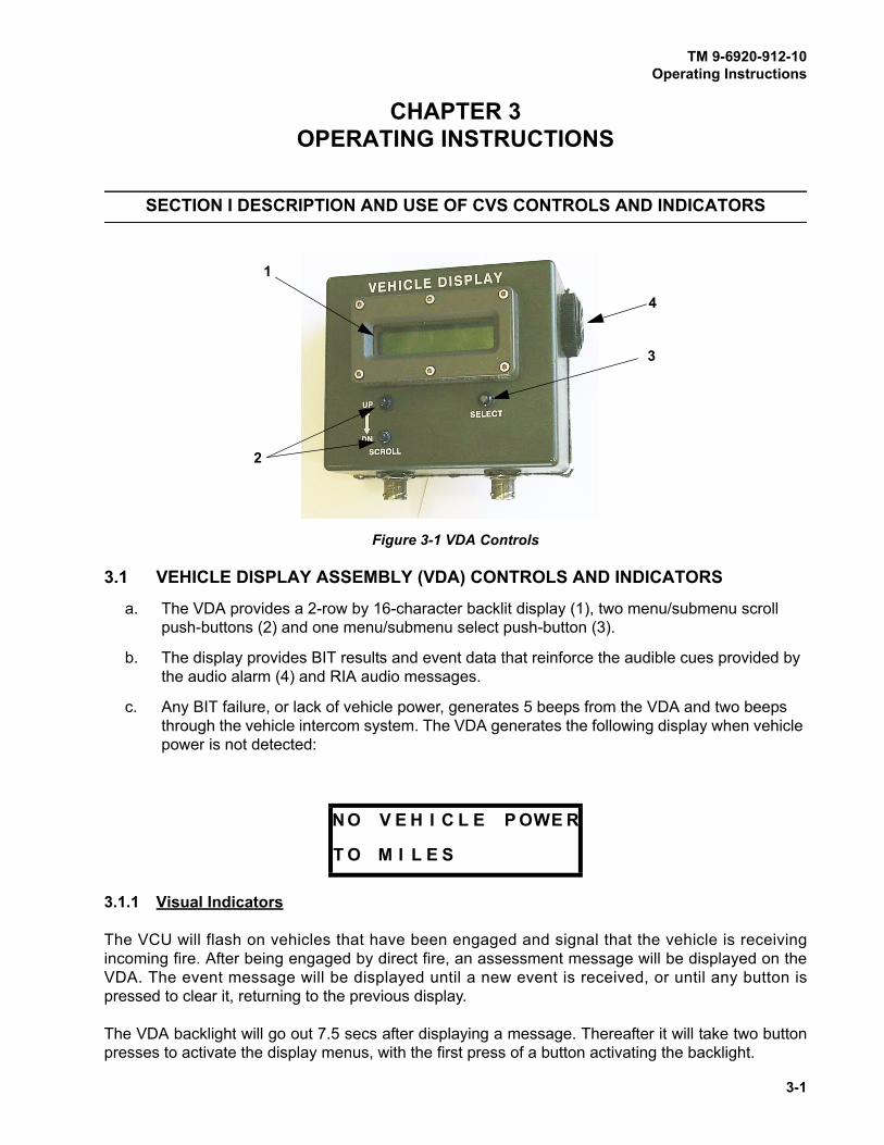
3-1 VDA Controls ............................................................................................................... 3-1
3-2 Detector Belt, Factory Configuration Label ................................................................ 3-10

TM 9-6920-912-10
TABLE OF CONTENTS (Continued)
LIST OF ILLUSTRATIONS (Continued)
Figure Title Page
vii
3-3 “SYSTEM CONFIG” Display ..................................................................................... 3-12
3-4 “SYSTEM CONFIG” Display ..................................................................................... 3-14
3-5 Detector Belt Testing .................................................................................................. 3-17
3-6 MGLT Locking Knobs and Alignment Knobs .............................................................. 3-22
3-7 Vehicle Hit Zones ....................................................................................................... 3-28
4-1 “SELECT SYSTEM CONFIG” Display ....................................................................... 4-5
4-2 General MILES XXI Troubleshooting ........................................................................... 4-7
4-3 VDA Has No Display .................................................................................................... 4-8
4-4 VDA Push-buttons Not Operational ............................................................................. 4-9
4-5 VDA Has No Backlight ............................................................................................... 4-10
4-6 VDA Buzzer Does Not Sound .................................................................................... 4-11
4-7 VCU Will Not Power Up ............................................................................................. 4-12
4-8 VCU Strobe CVKI Will Not Flash ................................................................................ 4-13
4-9 No RF Communication Between VCU and CD .......................................................... 4-14
4-10 General Faults, System Not Responding ................................................................... 4-15
4-11 Detector Belt Not Functioning .................................................................................... 4-16
4-12 HUTT Not Functioning Properly ................................................................................. 4-17
4-13 Audio Cues Not Being Heard ..................................................................................... 4-18
4-14 COAX Does Not Fire .................................................................................................. 4-19
4-15 Main Gun Will Not Fire ............................................................................................... 4-20
4-16 SAT Will Not Acquire/Learn ........................................................................................ 4-21
4-17 Operational Verification of the MILES XXI System .................................................... 4-22
C-1 M1A1 Abrams Series Vehicle ...................................................................................... C-1
C-2 Class 3A LASER Label ............................................................................................... C-2
C-3 Component Graphics .................................................................................................. C-5
C-4 Detector Belt Inspection .............................................................................................. C-8
C-5 Cable Inspection ......................................................................................................... C-9
C-6 VCU Inspection ......................................................................................................... C-10
C-7 VDA Inspection .......................................................................................................... C-11
C-8 MGLT Inspection ....................................................................................................... C-12
C-9 FCI Inspection ........................................................................................................... C-13
C-10 Terminator Inspection ................................................................................................ C-13
C-11 HUTT Inspection ....................................................................................................... C-14
C-12 Main Gun Mount Assembly Inspection ...................................................................... C-15
C-13 Coax Microphone Trigger Assembly Inspection ........................................................ C-16
C-14 RIA Inspection ........................................................................................................... C-17
C-15 VCU Mounting Bracket Assembly Inspection ............................................................ C-18
C-16 MILES XXI Transit Case Inspection .......................................................................... C-19
C-17 M2 SAT ...................................................................................................................... C-20
C-18 M240 SAT Inspection ................................................................................................ C-21
TM 9-6920-912-10
TABLE OF CONTENTS (Continued)
LIST OF TABLES
Figure Title Page
viii
2-1 TOOLS REQUIRED ..................................................................................................... 2-2
2-2 MILES XXI CVS KIT FOR M1A1/M1A2/M1A2 SEP ..................................................... 2-2
3-1 VDA DISPLAY MENUS ................................................................................................ 3-5
3-2 VDA Admin Menus ....................................................................................................... 3-7
3-3 EVENT TYPES .......................................................................................................... 3-33
3-4 MILES WEAPON CODES .......................................................................................... 3-34
4-1 PREVENTIVE MAINTENANCE CHECKS AND SERVICES (PMCS) .......................... 4-2
4-2 TROUBLESHOOTING ................................................................................................. 4-6
D-1 ACRONYM LIST ..........................................................................................................D-1
E-1 GLOSSARY DEFINITIONS ..........................................................................................E-1
TM 9-6920-912-10
1-1
CHAPTER 1INTRODUCTION
SECTION I GENERAL INFORMATION
1.1 SCOPE
This manual explains how to install, operate and maintain the Multiple Integrated LASER
Engagement System (MILES) XXI equipment for the Abrams series vehicles. Step-by-step
instructions are provided for all procedures necessary to use the system. Where distinction among
the vehicles is needed for different configurations, the text will refer to the specific vehicle. This
manual covers only authorized operator maintenance. Any maintenance problems not covered
should be referred to maintenance personnel.
1.1.1 Skills Needed to Use This Manual
To use this manual, you should be able to:
a. Aim and fire the vehicle weapons.
b. Operate vehicle In Accordance With (IAW) vehicle operation manuals and procedures.
c. If you cannot perform these tasks, ask your Tank Commander or supervisor to show you
how. When you can perform these tasks, continue using this manual.
Before using the equipment become familiar with this manual, especially the table of contents. This
manual contains information on how to inspect, install, operate, maintain and remove the equipment.
1.1.2 Purpose Of Equipment
MILES XXI simulates the effects of direct fire weapons as they would affect vehicles and soldiers
during an exercise. MILES XXI provides realistic training without the expense and environmental
impact of firing live ammunition.
1.1.3 Limitation Of Equipment
When engaging any MILES equipped aircraft, vehicles, or personnel, MILES XXI equipped weapons
simulate the range, effect, and operational capabilities of the weapon. However, a dirty transmitter
lens or environmental conditions may reduce the effective range of the LASER transmitters.

TM 9-6920-912-10Introduction
1-2
1.1.4 Corrosion Prevention and Control
a. Corrosion Prevention and Control (CPC) of Army material is a continuing concern. It is
important that any corrosion problems with this item be reported. Reported problems can be
corrected and improvements can be made to prevent reoccurrence in the future.
b. While corrosion is typically associated with rusting of metals, it can also include deterioration
of other materials such as rubber and plastic. Unusual cracking, softening, swelling, or
breaking of these materials may be a corrosion problem.
c. If a corrosion problem is identified, it can be reported using SF 368. Use of key words such
as “corrosion”, “rust”, “deterioration”, or “cracking” will assure that the information is identified
as a CPC problem.
d. The SF 368 should be submitted to Program Executive Office, Simulation, Training and
Instrumentation, ATTN: AMSTI-OPS, 12350 Research Parkway, Orlando, Fl 32826-3276.
1.1.5 Maintenance Forms and Records
Department of the Army forms and procedures used for equipment maintenance will be those
prescribed by DA PAM 738-750, The Army Maintenance Management System (TAMMS).
1.1.6 Destruction of Army Material to Prevent Enemy Use
MILES XXI is a training device and will not be used in a combat zone. Training devices do not meet
current war reserve criteria. Therefore, the destruction of this system is up to the judgment of the unit
commander.
1.1.7 Reporting Equipment Improvement Recommendations (EIR)
If the MILES XXI System needs improvement, let us know. You the user, can provide us with
concerns and recommendations on how to improve this equipment. Put it on the DA 2028 located in
the back of this publication and mail it to:
Commander, U.S. Army
Program Executive Office, Simulation, Training and Instrumentation (PEOSTRI)
ATTN: SFAE-STRI-OPS
12350 Research Parkway
Orlando FL. 32826-3276
We will send you a reply.

TM 9-6920-912-10
2-1
CHAPTER 2INSTALLATION INSTRUCTIONS
SECTION I EQUIPMENT INVENTORY
2.1 GENERAL
The following installation instructions are based on the common configuration of the vehicle. If the
vehicle is configured differently than shown, modify the installation tasks as necessary so you can
install the MILES XXI equipment as closely as possible to the locations shown.
Cables: Physical variations may require cables to be routed differently than described in this
manual. Use the installation instructions as general guidelines.
To avoid injury to personnel outside the vehicle, never install a cable in a place
where it could cause a soldier to trip or fall off the vehicle.
To avoid damaging MILES XXI equipment:
z Securely attach each cable to the surface of the vehicle.
z Always test the movement of the hatches before securing the cables to tie
points.
z Ensure the cables do not prevent the turret from traversing and elevating.
2.1.1 Equipment Inventory and Inspection Notes
Inventory and inspect equipment prior to installation to ensure you have all equipment required and
that it is serviceable. Refer to Table 2-2 (MILES XXI CVS KIT FOR M1A1/M1A2/M1A2 SEP). Use the
inspection procedures described in Appendix C.
WARNING
CAUTION
M1A1/A2/SEP Tank MILES XXI CVS KitDevice Number (DVC #) 17-236
National Stock Number (NSN) 6920-01-543-0475
Manufacturer’s Part Number 2031915-1

TM 9-6920-912-10Installation Instructions
2-2
2.2 EQUIPMENT NEEDED
Request all equipment needed to install and operate the MILES XXI CVS for the Abrams vehicles.
Inspect the equipment for visible damage and inventory to ensure all required equipment is present.
Table 2-1 TOOLS REQUIRED
Flat Tip Screw Driver 1/2" Dr. Ratchet 6" Extension, 1/2" Dr. 1/2" Dr. 7/16" Socket
1/2" Dr. 9/16" Socket 7/16" Open End Box 9/16" Open End Box 15/16" Open End Box
1/2" Dr. 5/8" Socket 1/2" Dr. Torque Wrench
Table 2-2 MILES XXI CVS KIT FOR M1A1/M1A2/M1A2 SEP
PART NO. DESCRIPTION QTY
2031470-2 or
2031470-3
MAIN GUN LASER TRANSMITTER (MGLT) 1
2030464-2 VEHICLE CONTROL UNIT (VCU) 1
2030754-1 RADIO INTERFACE ASSEMBLY (RIA) 1
2031236-1 FIRE CONTROL INTERFACE (FCI) 1
2030753-2 VEHICLE DISPLAY ASSEMBLY (VDA) 1
2030642-2 HULL-TO-TURRET TRANSMITTER (HUTT) 1
2031050-6 LASER DETECTOR BELT #4 1
2031050-2 LASER DETECTOR BELT #6 3
2031038-4 CABLE ASSEMBLY, SYSTEM BUS 4
2031038-8 CABLE ASSEMBLY, SYSTEM BUS 2
2030485-2 CABLE ASSEMBLY, RIA 1
2031481-1 CABLE ASSEMBLY, DIFCUE 1
2031482-1 CABLE ASSEMBLY, MAIN GUN SIGNATURE SIMULATOR (MGSS) 1
2031438-2 CABLE ASSEMBLY, VCU 1
2031480-1 CABLE ASSEMBLY, POWER 1
2031496-1 CABLE ASSEMBLY, MGLT 1
2031588-1 CABLE ASSEMBLY, M1A1 FCI 1
2031589-1 CABLE ASSEMBLY, M1A2/M1A2 SEP FCI 1
2031039-16 CABLE ASSEMBLY, SYSTEM BUS 1
2031039-6 CABLE ASSEMBLY, SYSTEM BUS 1
2031560-1 VCU BRACKET 1
2031030 TERMINATOR 2

TM 9-6920-912-10Installation Instructions
2-3
SECTION II INSTALLATION TASKS
2.3 GENERAL
z Ensure master power is off.
z Fastener tape primer is highly flammable. Do not spray near heat, sparks,
or open flame. Use only in well ventilated areas.
z Do not spray fastener tape primer on periscopes or sights.
Fastener Tape
A large part of the MILES XXI equipment is installed on the vehicle using hook and pile fastener tape.
This task will show you where the hook fastener tape is required. Installation instructions are the
same when fastener tape is required. Read the following general instructions first to familiarize
yourself with how to install fastener tape.
NOTES
Always inspect the vehicle for existing fastener tape. If tape has been installed
and in good condition, leave it in place. New tape is only necessary when old
tape is damaged or not installed.
The following procedures provide instructions for standard MILES XXI
component installation on the vehicle.
a. Look carefully at the designated areas in the following figures where MILES XXI equipment
is installed on the vehicle.
b. Clean areas using water, brush, and rags. Tape will not stick to dirty, greasy, wet or rough
surfaces.
2030690-2 COAX MIC TRIGGER ASSEMBLY 1
2030911-1 TRANSIT CASE 1
2030912-3 TRANSIT CASE 1
2031555-1 MGLT MOUNTING BRACKET 1
2030983-1 SEAL, PERISCOPE 1
2030680-15 LASER TRANSMITTER, M2 1
2030680-10 LASER TRANSMITTER, M240 1
CAUTION
Table 2-2 MILES XXI CVS KIT FOR M1A1/M1A2/M1A2 SEP (Continued)
PART NO. DESCRIPTION QTY

TM 9-6920-912-10Installation Instructions
2-4
c. After you have cleaned the areas described, mark the areas where each piece of MILES XXI
equipment will be attached with chalk.
d. To mark equipment locations, lay each piece of equipment in the location described in this
task. Mark the outline of each piece of equipment with chalk on the vehicle to help locate the
fastener tape placement.
NOTE
Don’t spray adhesive glue or add fastener tape where there is already tape in
good condition.
e. Get a can of spray adhesive and a roll of “hooked” fastener tape.
NOTE
Avoid installing tape directly over weld lines, bolts, screw heads, or other
obstructions.
Figure 2-1 Spray Adhesive and Fastener Tape

TM 9-6920-912-10Installation Instructions
2-5
Hatch covers could fall and injure personnel. Keep head and hands clear
when opening or closing hatch covers.
To avoid injury during equipment installation, do the following before
performing any of the installation tasks.
a. Ensure vehicle MASTER POWER and TURRET POWER are set to the OFF position.
b. (M1A1 Only) Ensure Turret Utility Power is set to OFF.
c. Ensure the Commander’s and Loader’s HATCHES are LOCKED in the FULL OPEN
position.
NOTE
If tape has already been installed on the vehicle and is in good shape, proceed
to TASK 1 (Install Detector Belt To Turret Left Side), in Section IV of this
Chapter.
a. Clean areas where fastener tape is shown in the following figures, using water, brush and
rags. Tape will not stick to dirty, greasy, wet or rough surfaces.
b. Clean areas inside vehicle as shown in the follow-on sections.
TASK
1 Conduct Vehicle Safety Checks and Ready Vehicle for Installation
WARNING
TASK
2 Prepare Vehicle Surfaces

TM 9-6920-912-10Installation Instructions
2-6
SECTION III FASTENER TAPE INSTALLATION
NOTES
When LEFT, RIGHT, FRONT and REAR references are used, it refers to
positions relative to the driver while seated in the drivers compartment facing
the front of the vehicle.
Installation procedures may be conducted in parallel using some or all of the
crew members to expedite installation.
Sub-task 1.1 Install Fastener Tape to Turret Left Side
a. Mark the area with chalk from the front left of the turret to a point past the rear of the left tow
cable holder as shown.
b. Spray a heavy coat of adhesive in the marked area.
c. Let adhesive dry for 3-5 minutes before applying fastener tape.
d. Cut tape to fit the area.
TASK
1 Install Fastener Tape
Figure 2-2 Turret Left Side Fastener Tape Installation
TM 9-6920-912-10Installation Instructions
2-7
e. Remove the protective paper backing from the tape. For short lengths, the entire backing
may be removed before mounting the tape. For long pieces of tape, remove the backing
material as the tape is installed.
f. Press the tape firmly in place with your hand or a hand roller. You can also use the lid of the
spray can or the head of a ball-peen hammer as a roller to press the tape firmly in place.
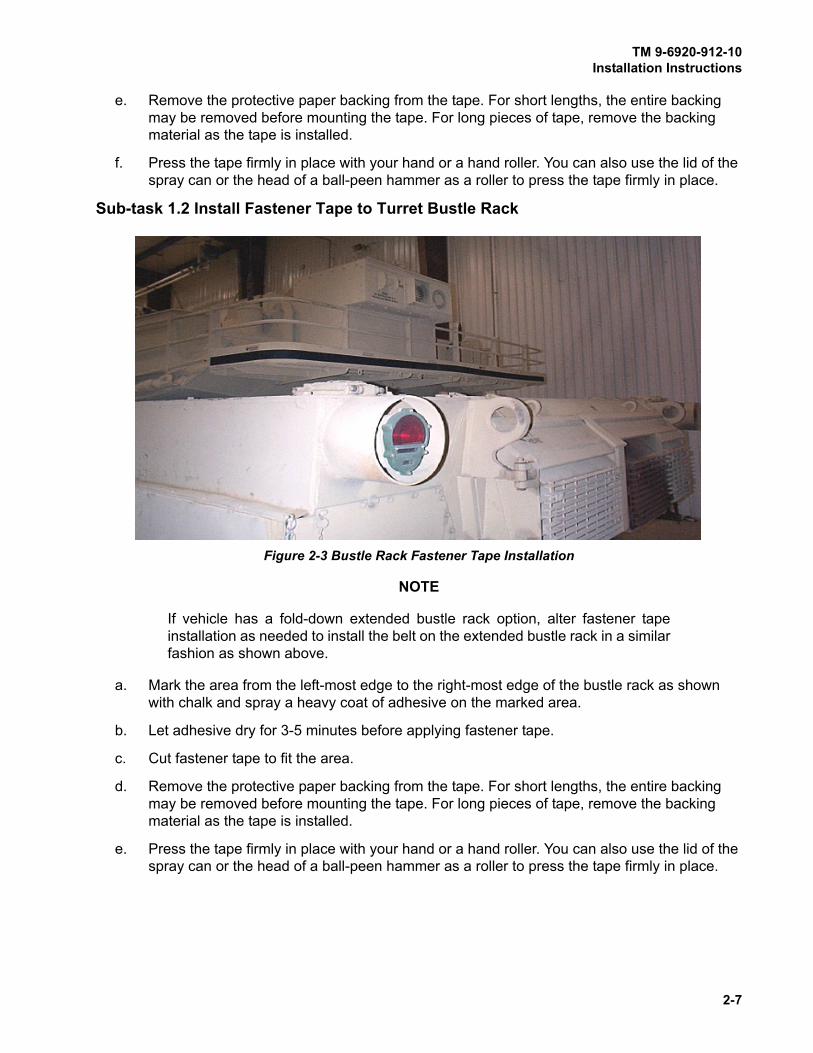
Sub-task 1.2 Install Fastener Tape to Turret Bustle Rack
NOTE
If vehicle has a fold-down extended bustle rack option, alter fastener tape
installation as needed to install the belt on the extended bustle rack in a similar
fashion as shown above.
a. Mark the area from the left-most edge to the right-most edge of the bustle rack as shown
with chalk and spray a heavy coat of adhesive on the marked area.
b. Let adhesive dry for 3-5 minutes before applying fastener tape.
c. Cut fastener tape to fit the area.
d. Remove the protective paper backing from the tape. For short lengths, the entire backing
may be removed before mounting the tape. For long pieces of tape, remove the backing
material as the tape is installed.
e. Press the tape firmly in place with your hand or a hand roller. You can also use the lid of the
spray can or the head of a ball-peen hammer as a roller to press the tape firmly in place.
Figure 2-3 Bustle Rack Fastener Tape Installation

TM 9-6920-912-10Installation Instructions
2-8
Sub-task 1.3 Install Fastener Tape to Turret Right Side
a. Mark the area with chalk from the front right of the turret to a point past the rear of the right
tow cable holder as shown.
b. Spray a heavy coat of adhesive in the marked area.
c. Let adhesive dry for 3-5 minutes before applying fastener tape.
d. Cut fastener tape to fit the area.
e. Remove the protective paper backing from the tape. For short lengths, the entire backing
may be removed before mounting the tape. For long pieces of tape, remove the backing
material as the tape is installed.
f. Press the tape firmly in place with your hand or a hand roller. You can also use the lid of the
spray can or the head of a ball-peen hammer as a roller to press the tape firmly in place.
Figure 2-4 Turret Right Side Fastener Tape Installation

TM 9-6920-912-10Installation Instructions
2-9
Sub-task 1.4 Install Fastener Tape to Turret Front
a. Mark the area across the turret front left and right and over the main gun as shown with
chalk.
b. Spray a heavy coat of adhesive on the areas.
c. Let adhesive dry for 3-5 minutes before applying fastener tape.
d. Cut fastener tape to fit the area.
e. Remove the protective paper backing from the tape. For short lengths, the entire backing
may be removed before mounting the tape. For long pieces of tape, remove the backing
material as the tape is installed.
f. Press the tape firmly in place with your hand or a hand roller. You can also use the lid of the
spray can or the head of a ball-peen hammer as a roller to press the tape firmly in place.
Figure 2-5 Turret Front Fastener Tape Installation

TM 9-6920-912-10Installation Instructions
2-10
Sub-task 1.5 Install HUTT Fastener Tape
a. Locate the area on the rear of the battery box as shown.
b. Spray a heavy coat of adhesive on the area.
c. Let adhesive dry for 3-5 minutes before applying fastener tape.
d. Cut 2 ea. 6 inch strips of tape to fit the area. Remove the fastener tape backing.
e. Press the tape firmly in place with your hand or a hand roller. You can also use the lid of the
spray can or the head of a ball-peen hammer as a roller to press the tape firmly in place.
Figure 2-6 HUTT Fastener Tape Installation
TM 9-6920-912-10Installation Instructions
2-11
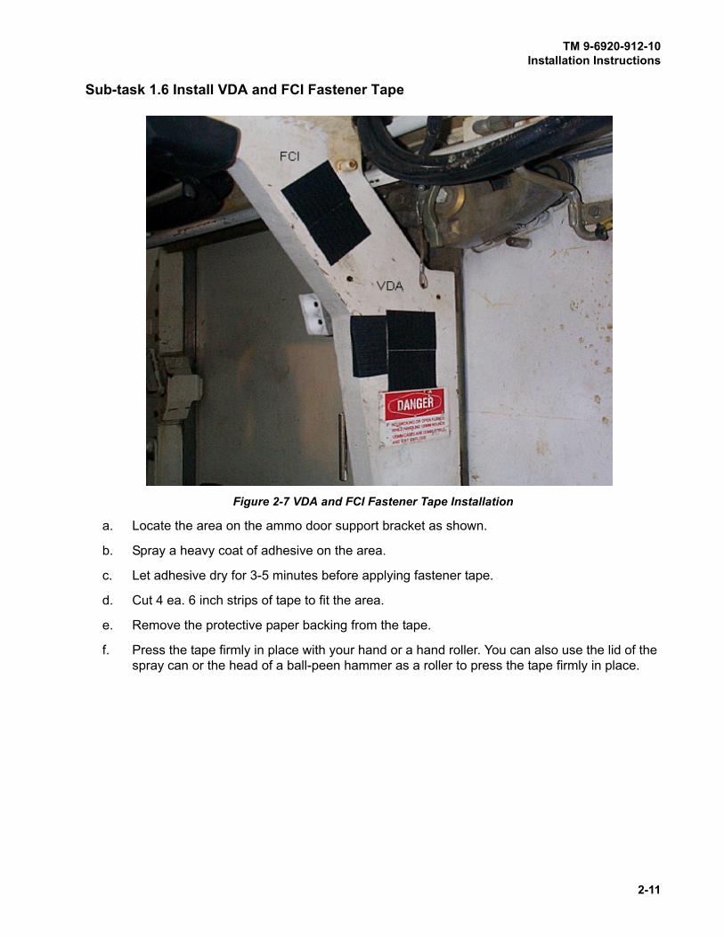
Sub-task 1.6 Install VDA and FCI Fastener Tape
a. Locate the area on the ammo door support bracket as shown.
b. Spray a heavy coat of adhesive on the area.
c. Let adhesive dry for 3-5 minutes before applying fastener tape.
d. Cut 4 ea. 6 inch strips of tape to fit the area.
e. Remove the protective paper backing from the tape.
f. Press the tape firmly in place with your hand or a hand roller. You can also use the lid of the
spray can or the head of a ball-peen hammer as a roller to press the tape firmly in place.
Figure 2-7 VDA and FCI Fastener Tape Installation

TM 9-6920-912-10Installation Instructions
2-12
Sub-task 1.7 Install RIA Fastener Tape
NOTE
Cover removed for clarity.
a. Locate an area in front of the ammo door under the Master Control Station (MCS) as shown.
Clean then spray a heavy coat of adhesive on the area.
b. Let adhesive dry for 3-5 minutes before applying fastener tape.
c. Cut 1 ea. 6 inch strip of tape to fit the area. Remove the fastener tape backing.
d. Press the tape firmly in place with your hand or a hand roller. You can also use the lid of the
spray can as a roller to press the tape firmly in place.
Figure 2-8 RIA Fastener Tape Installation

TM 9-6920-912-10Installation Instructions
2-13
SECTION IV EQUIPMENT INSTALLATION
NOTES
When LEFT, RIGHT, FRONT and REAR references are used, it refers to
positions relative to the driver while seated in the drivers compartment facing
the front of the vehicle.
Installation procedures may be conducted in parallel using some or all of the
crew members to expedite installation.
For ease of detector belt and cable connections, we refer to detector belt and
cable locations on the vehicle. Refer to Figure 2-9 (Vehicle Detector Belt
Location).
a. The detector belts are configured at the warehouse for placement on the vehicle.
b. Labels are placed on the detector belt electronics module by CLS personnel, which dictate
TASK
1 Install Detector Belt To Turret Left Side
Figure 2-9 Vehicle Detector Belt Location
FRONT BELT (1)(PN 2031050-6)
LEFT BELT (4)(PN 2031050-2)
RIGHT BELT (2)(PN 2031050-2)
REAR BELT (3)(PN 2031050-2)
TM 9-6920-912-10Installation Instructions
2-14
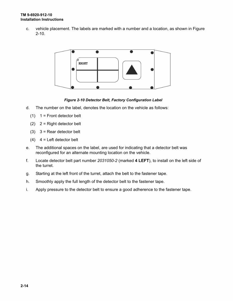
c. vehicle placement. The labels are marked with a number and a location, as shown in Figure
2-10.
d. The number on the label, denotes the location on the vehicle as follows:
(1) 1 = Front detector belt
(2) 2 = Right detector belt
(3) 3 = Rear detector belt
(4) 4 = Left detector belt
e. The additional spaces on the label, are used for indicating that a detector belt was
reconfigured for an alternate mounting location on the vehicle.
f. Locate detector belt part number 2031050-2 (marked 4 LEFT), to install on the left side of
the turret.
g. Starting at the left front of the turret, attach the belt to the fastener tape.
h. Smoothly apply the full length of the detector belt to the fastener tape.
i. Apply pressure to the detector belt to ensure a good adherence to the fastener tape.
Figure 2-10 Detector Belt, Factory Configuration Label

TM 9-6920-912-10Installation Instructions
2-15
a. Locate detector belt part number 2031050-2 (marked 3 REAR).
b. Starting at the left rear of the turret, attach the belt to the fastener tape across the bottom of
the bustle rack.
c. Smoothly apply the full length of the detector belt to the fastener tape.
d. Apply pressure to the detector belt to ensure a good adherence to the fastener tape.
a. Locate detector belt part number 2031050-2 (marked 2 RIGHT).
b. Starting at the right rear of the turret, attach the belt to the fastener tape.
c. Smoothly apply the full length of the detector belt to the fastener tape.
d. Apply pressure to the detector belt to ensure a good adherence to the fastener tape.
NOTE
Ensure that the belt electronics unit is securely attached to a flat surface, and
does not lay across a bolt head or seam.
a. Locate detector belt part number 2031050-6 (marked 1 FRONT),.
b. Starting at the front right of the turret, attach the belt to the fastener tape.
c. Smoothly apply the full length of the detector belt to the fastener tape.
d. Apply pressure to the detector belt to ensure a good adherence to the fastener tape.
TASK
2 Install Detector Belt To Turret Rear
TASK
3 Install Detector Belt To Turret Right Side
TASK
4 Install Detector Belt To Turret Front
TM 9-6920-912-10Installation Instructions
2-16
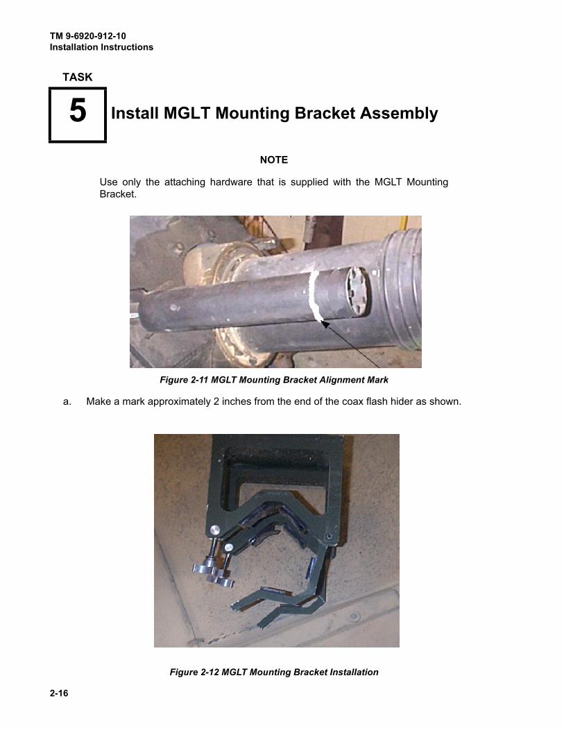
NOTE
Use only the attaching hardware that is supplied with the MGLT Mounting
Bracket.
a. Make a mark approximately 2 inches from the end of the coax flash hider as shown.
TASK
5 Install MGLT Mounting Bracket Assembly
Figure 2-11 MGLT Mounting Bracket Alignment Mark
Figure 2-12 MGLT Mounting Bracket Installation

TM 9-6920-912-10Installation Instructions
2-17
b. Position the MGLT mounting bracket on the flash hider with the tightening knobs towards the
main gun and the front of the bracket aligned with the alignment mark made on the flash
hider.
c. Secure the bracket by swinging the hinges onto the tightening knobs and tighten.
a. Secure the MGLT to the MGLT Mounting Bracket using the four captive mounting bolts on
the MGLT, using a 9/16" wrench.
NOTES
MILES boresight will NOT be maintained unless the two knobs on the MGLT
Bracket, and four captive bolts on the MGLT, are ALL properly secured.
Use only the attaching hardware that is supplied with the MGLT Mounting
Bracket.
TASK
6 Install Main Gun Laser Transmitter (MGLT)
Figure 2-13 MGLT Installation
TM 9-6920-912-10Installation Instructions
2-18
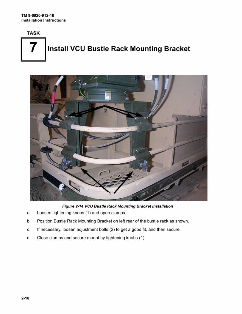
a. Loosen tightening knobs (1) and open clamps.
b. Position Bustle Rack Mounting Bracket on left rear of the bustle rack as shown.
c. If necessary, loosen adjustment bolts (2) to get a good fit, and then secure.
d. Close clamps and secure mount by tightening knobs (1).
TASK
7 Install VCU Bustle Rack Mounting Bracket
Figure 2-14 VCU Bustle Rack Mounting Bracket Installation
2

TM 9-6920-912-10Installation Instructions
2-19
a. Position VCU on the Mounting Bracket with power switch facing forward and secure it with
the four captive mounting bolts (1) using 7/16" wrench.
TASK
8 Install Vehicle Control Unit (VCU)
Figure 2-15 VCU Installation
1
(1) Two oneach side.
TM 9-6920-912-10Installation Instructions
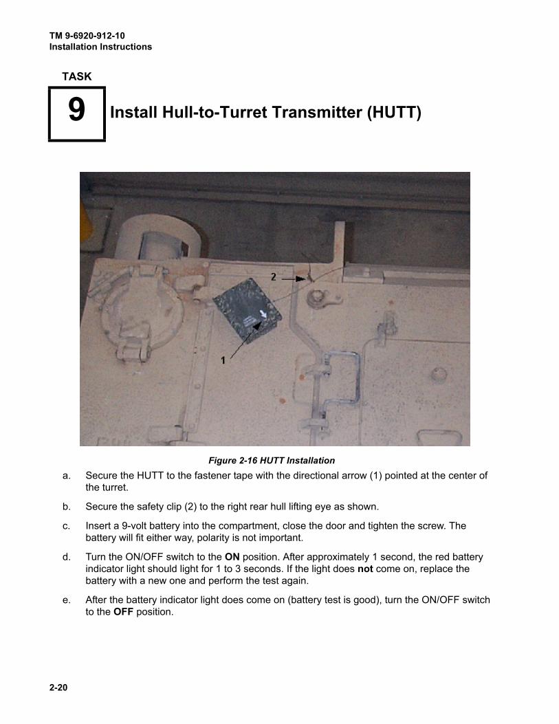
2-20
a. Secure the HUTT to the fastener tape with the directional arrow (1) pointed at the center of
the turret.
b. Secure the safety clip (2) to the right rear hull lifting eye as shown.
c. Insert a 9-volt battery into the compartment, close the door and tighten the screw. The
battery will fit either way, polarity is not important.
d. Turn the ON/OFF switch to the ON position. After approximately 1 second, the red battery
indicator light should light for 1 to 3 seconds. If the light does not come on, replace the
battery with a new one and perform the test again.
e. After the battery indicator light does come on (battery test is good), turn the ON/OFF switch
to the OFF position.
TASK
9 Install Hull-to-Turret Transmitter (HUTT)
Figure 2-16 HUTT Installation

TM 9-6920-912-10Installation Instructions
2-21
NOTE
If vehicle is equipped with an extended bustle-rack, the HUTT may not be able
to communicate reliably with the Rear Detector belt when the turret is
positioned with the gun-tube forward, and "HUTT MISSING" errors may
appear on the MILES XXI System.
If the extended bustle-rack is used, it is recommended that several layers of
fastener tape be used under the front end of the HUTT to angle it upward for
better detector coverage, as illustrated in Figure 2-16a
Figure 2-16a HUTT Mounting For Extended Bustle-Rack Coverage
TASK
10 Install M240 Coax Machine Gun Microphone
Figure 2-17 Coax Microphone Installation
�
2
1

TM 9-6920-912-10Installation Instructions
2-22
a. Install M240 Blank Firing Adapter (BFA-M21) over the flash hider as shown (1). (Refer to TM
9-1005-316-12&P)
b. Secure the Coax Mic Trigger (2) to the BFA as shown.
c. Set the cable on top of the turret. It will be connected in a later Task.
- If MGSS is provided, refer to TM 9-6920-892-10 for installation and operating instructions.
- If DIFCUE is provided, refer to TM 9-6920-893-10 for installation and operating instructions.
TASK
11 Install Main Gun Signature Simulator (MGSS)
TASK
12 Install Direct/Indirect Fire CUE (DIFCUE)
TM 9-6920-912-10Installation Instructions
2-23
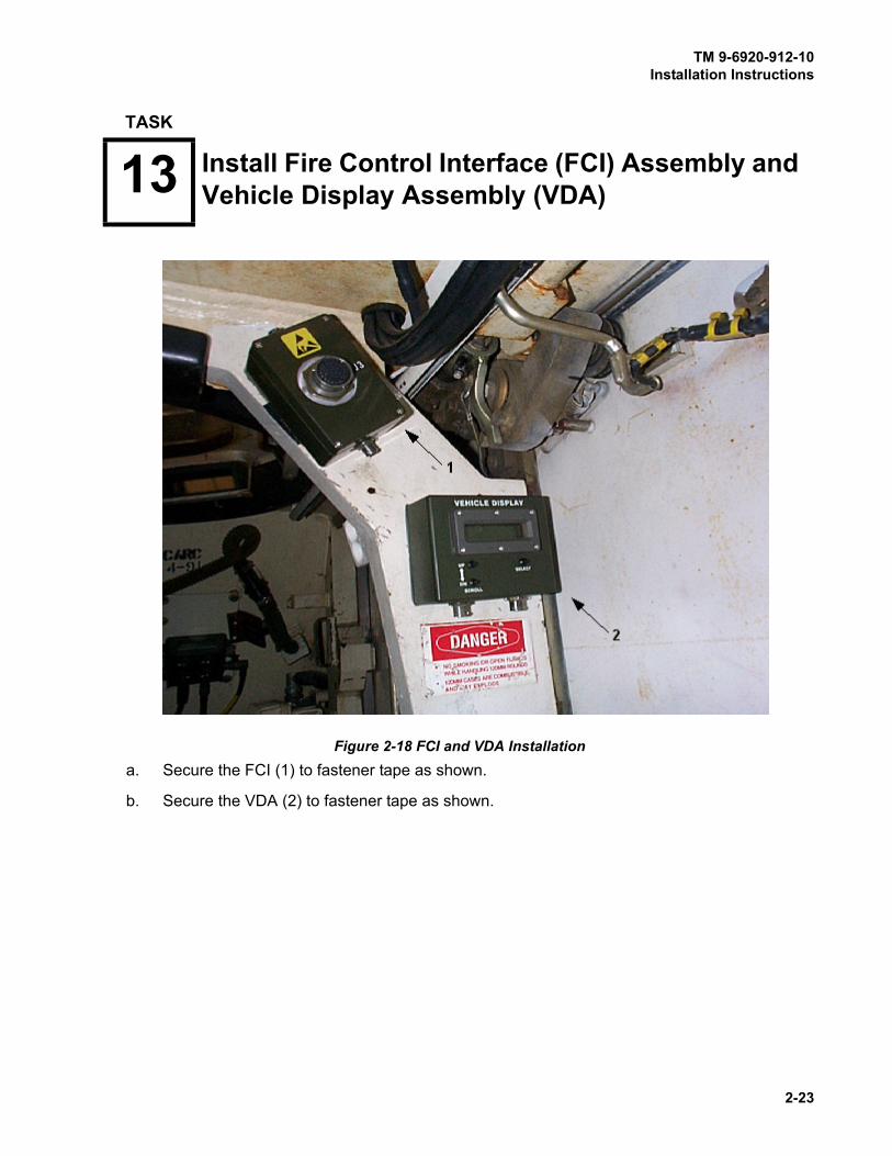
.
a. Secure the FCI (1) to fastener tape as shown.
b. Secure the VDA (2) to fastener tape as shown.
TASK
13 Install Fire Control Interface (FCI) Assembly and Vehicle Display Assembly (VDA)
Figure 2-18 FCI and VDA Installation

TM 9-6920-912-10Installation Instructions
2-24
a. Locate fastener tape on turret ring below the MCS.
b. Secure the RIA to the turret ring, utilizing fastener tape as shown.
TASK
14 Install Radio/Communications Interface Assembly (RIA)
Figure 2-19 RIA Installation
TM
9-6
92
0-9
12-1
0
2-2
5
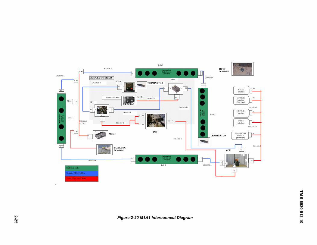
Figure 2-20 M1A1 Interconnect Diagram
P
Det
ecto
r Bel
t R
ear (
6)
2031
050-
2
MGLT
Rear 3
TERMINATOR
2031496-1 P1 – P5
TERMINATOR
TNB
2031588-1
2031039-16
2031038-8
2031039-6
2031038-4
J3
FCI
J2 P2J1
J3
MCS2030485-2
RIA
P1
P3
2031038-4
2031038-4
P1
P2 -
P1 - TJ1
TJ2
UJ1 P1
2031480-1
J1
P1
System BUS Cables
Detector Belts
P22031038-4
P1 P2
2031038-8
P4
P 5
P1
Power/System Cables
COAX MIC 2030690-2
P3 P1
Front 1
N/A
HUTT2030642-2
VEHICLE INTERIOR
P2
P1
P1
P2
P1
P2
J2
P2
P2
J1 P2
J1 J2
Det
ecto
r Bel
t Fr
ont (
4)
2031
050-
6
ATWESS Interface
(Not Used)
P2
J4
P2
Detector Belt Right Side (6)
2031050-2
VDA
Left 4
Detector Belt Left Side (6)
2031050-2
J1
J2
J3
2031438-2
RS-232 Interface
P3
P4
P6FLASHWESS Interface
(Not Used)
DIFCUE Interface
P5MGSSInterface
P1
P1
2031482-1
2031481-1
VCU
To MCS Audio Inputs
Right 2

TM
9-6
92
0-9
12
-10
2-2
6
Figure 2-21 M1A2 Interconnect Diagram
Det
ecto
r Bel
t R
ear (
6)
2031
050-
2
MGLT
Rear 3
TERMINATOR
2031496-1 P1 – P5
TERMINATOR
2031589-1
2031039-16
2031038-8
2031039-6
2031038-4
J1
J3
FCI
J2 P2 J1
J3
P1 MCS
2030485-2
RIA
P1 P2
P2
2031038-4
2031038-4
P1
UJ1 P1
2031480-1
J1
P1
System BUS Cables
Detector Belts
P2 2031038-4
P1 P2
2031038-8
P4
P5
P1
Power/System Cables
COAX MIC 2030690-2
P3 P1
Front 1
N/A
HUTT 2030642-2
FCEU P1 TJ2
VEHICLE INTERIOR
P2
J2 P2 J1
P1
P2
J2
P1
Det
ecto
r Bel
t Fr
ont (
4)
2031
050-
6
ATWESS Interface
(Not Used)
Detector Belt Right Side (6)
2031050-2
Detector Belt Left Side (6)
2031050-2
J1
J2 J4
J3
2031438-2
To MCS Audio Inputs
RS-232 Interface
P2
P3
P4
P6 FLASHWESS Interface
(Not Used)
DIFCUE Interface
P5 MGSS Interface
P1
P1
P2
P2
P2
VDA
VCU
Right 2
Left 4

TM
9-6
92
0-9
12-1
0
2-2
7 Figure 2-22 M1A2 SEP Interconnect Diagram
Det
ecto
r Bel
t R
ear (
6)
2031
050-
2
MGLT
Rear 3
TERMINATOR
2031496-1 P1 – P5
TERMINATOR
2031589-1
2031039-16
2031038-8
2031039-6
2031038-4
J2 J1
J3
FCI
J2 P2 J1
J3
P1 MCS 2030485-2
RIA
P1 P2
P2
2031038-4
2031038-4
P1
P1
2031480-1
J1
P1
System BUS Cables
Detector Belts
P22031038-4
P1 P2
2031038-8
P4
P5
P1
Power/System Cables
COAX MIC 2030690-2
P3 P1
Front 1
N/A
HUTT 2030642-2
FCEU P1 TJ2
VEHICLE INTERIOR
P1
P2
P2 P2
P1
P2
P2
J2 J1
Det
ecto
r Bel
t Fr
ont (
4)
2031
050-
6
ATWESS Interface
(Not Used)
Detector Belt Right Side (6)
2031050-2
Detector Belt Left Side (6)
2031050-2
J1
J2 J4
J3
2031438-2
To MCS Audio Inputs
RS-232 Interface
P2
P3
P4
P6 FLASHWESS Interface
(Not Used)
DIFCUE Interface
P5 MGSS Interface
P1
P1
P2
VDA
VCU
Right 2
Left 4
2031481-1
2031482-1

TM 9-6920-912-10Installation Instructions
2-28
Cables can become damaged during turret rotation if not properly secured.
Ensure that cables are attached so that turret rotation does not interfere with
the cables.
NOTES
Refer to the appropriate TM to remove loader’s periscope.
Refer to the appropriate Interconnect Diagram, Figure 2-20, Figure 2-21, or
Figure 2-22 for all cable installations.
Secure all cables after they are in place with the fastener tape strips attached
to the cables. Plastic cable ties may also be used. You may vary the
attachment points and routing on the vehicle for convenience.
Sub-task 15.1 Connect MGLT Adapter Cable
a. Locate MGLT Cable 2031496-1.
Figure 2-23 MGLT Cable (2031496-1) Routing
TASK
15 Install System Cables
CAUTION
MGLT Cable
2031496-1
P5 to Coax Mic
P1 to MGLT J1

TM 9-6920-912-10Installation Instructions
2-29
b. Connect P1 of Adapter Cable 2031496-1 to MGLT J1.
c. Connect coax mic 2030690-2 to P5 on the MGLT Adapter Cable 2031496-1.
d. Connect dust cap 660-008NF08S6-50 to P4 on the MGLT cable.
Sub-task 15.2 Connect System BUS Cables
a. Remove the loaders periscope and store in sponson box. Insert periscope seal P/N
2030983-1, into the periscope opening.
b. Locate system BUS cable 2031039-6.
c. Connect P2 of system BUS cable 2031039-6 to the “rear” of the left side belt, and P1 to J2 of
the VCU.
Figure 2-24 System Bus Cable (2031039-6) Routing
d. Locate system BUS cable 2031038-8.
e. Connect P1 of system BUS cable 2031038-8 between the “left” side front detector belt, and
P2 to the “front” of the left belt.
System BUS Cable
2031039-6
P1 to VCU J2P2 to Left Belt

TM 9-6920-912-10Installation Instructions
2-30
Figure 2-25 System Bus Cable (2031038-8) Routing
f. Locate system BUS cable 2031038-4.
g. Connect P2 of system BUS cable 2031038-4 to the “right” side of the front belt, and P1 to the
MGLT Adapter Cable-P2.
Figure 2-26 System Bus Cable (2031038-4) Routing
h. Locate system BUS cable 2031038-8.
System BUS Cable
2031038-8
P2 to Left Belt
P1 to Front Belt
System BUS Cable
2031038-4
P2 to Front Belt
P1 to MGLT Adapter P2

TM 9-6920-912-10Installation Instructions
2-31
i. Connect P2 of system BUS cable 2031038-8 to the “front” of the right detector belt, and
connect P1 to the MGLT Adapter Cable - P3.
Figure 2-27 System BUS Cable 2031038-8 Cable Routing
j. Locate system BUS cable 2031038-4.
k. Connect P2 of system BUS cable 2031038-4 to the right side of the “rear” detector belt and
P1 to the “rear” of the right side detector belt.
Figure 2-28 System Bus Cable 2031038-4 Cable Routing
l. Locate a Terminator 2031030.
P2 to Right Belt
System BUS Cable
2031038-8P1 to MGLT Adapter
Cable P3
P1 to Right BeltP2 to Rear Belt
System BUS Cable
2031038-4
TM 9-6920-912-10Installation Instructions
2-32
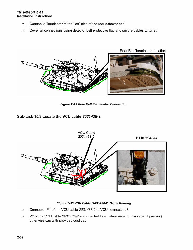
m. Connect a Terminator to the “left” side of the rear detector belt.
n. Cover all connections using detector belt protective flap and secure cables to turret.
Figure 2-29 Rear Belt Terminator Connection
Sub-task 15.3 Locate the VCU cable 2031438-2.
Figure 2-30 VCU Cable (2031438-2) Cable Routing
o. Connector P1 of the VCU cable 2031438-2 to VCU connector J3.
p. P2 of the VCU cable 2031438-2 is connected to a instrumentation package (if present)
otherwise cap with provided dust cap.
Rear Belt Terminator Location
P1 to VCU J3
VCU Cable
2031438-2

TM 9-6920-912-10Installation Instructions
2-33
q. Ensure dust caps 660-008NF08S6-50 are connected to P3 and P6 (not used), on the VCU
cable 2031438-2.
r. P4 of the VCU cable 2031438-2 is used to connect the DIFCUE trigger cable (2031481-1) if
the DIFCUE is to be used during the exercise.
s. P5 of the VCU cable 2031438-2 is used to connect the MGSS trigger cable 2031482-1 if the
MGSS is to be used during the exercise.
Sub-task 15.4 Connect Turret Exterior System Cables
a. Locate system cable 2031039-16.
Figure 2-31 System Cable (2031039-16) Routing
b. Connect P1 of system cable 2031039-16 to J1 on the VCU.
c. Route cable through the loaders periscope.
d. Locate power cable 2031480-1.
P1 to VCU J1
P2 through Loader’s Periscope
System Cable
2031039-16

TM 9-6920-912-10Installation Instructions
2-34
.
Figure 2-32 Power Interface Cable (2031480-1) Routing
e. Connect P2 of power interface cable 2031480-1 to J4 of the VCU.
f. Route cable through the loader’s periscope.
Sub-task 15.5 Connect Turret Interior System Cables
a. Locate system cable 2031039-16 coming from loader’s periscope. Connect P2 to J2 (1) on
the RIA. Locate system BUS cable 2031038-4 and connect P1 to J1 (2) on the RIA.
Figure 2-33 RIA Connections
b. Using system BUS cable 2031038-4 from the RIA, connect P2 to J2 (3) on the FCI.
P2 to VCU J4
P1 through Loader’s Periscope
System Cable
2031480-1
12

TM 9-6920-912-10Installation Instructions
2-35
Figure 2-34 FCI and VDA Connections
c. Locate system BUS cable 2031038-4 and connect P1 to J1 (4) on the FCI. Connect P2 to J1
(5) on the VDA.
d. Locate and install a Terminator on J2 (6) on the VDA.
e. Locate RIA (audio) Cable 2030485-2. Connect P1 to RIA J3 and the Audio Input terminals
(or System Lines) to the Master Control Station (MCS). Blue wire to left terminal, white wire
to right terminal.
Figure 2-35 MCS Connections
34
5
6

TM 9-6920-912-10Installation Instructions
2-36
NOTES
For M1A1 vehicles, complete Task 16 (Install M1A1 Specific Cables).
For M1A2/M1A2 SEP vehicles, proceed to Task 17 (Install M1A2/M1A2 SEP
Specific Cables).
Sub-task 16.1 Install Trigger Cable
NOTE
On RTNB, TJ1 AND TJ2 are located further down, near the bottom of the unit.
a. Locate FCI Cable Assembly 2031588-1.
b. Connect the FCI Cable Assembly 2031588-1 P3 to the FCI J3 (3).
c. Connect 2031588-1 P1 to TJ1 (1) on the TNB or RTNB.
TASK
16 Install M1A1 Specific Cables
Figure 2-36 M1A1 Trigger and Power Cable Installation

TM 9-6920-912-10Installation Instructions
2-37
d. Connect 2031588-1 P2 to TJ2 (2) on the TNB or RTNB.
Sub-task 16.2 Install Power Cable
a. Locate Power Interface Cable 2031480-1 routed thru the loader’s periscope. Connect P1 to
UJ1(3) on the TNB.
b. Secure all cables.
NOTE
For M1A1 vehicle, proceed to Task 18 after completion of this task.
Sub-task 17.1 Install Trigger Cable
a. Remove Fire Control Electronics Unit (FCEU) protective cover.
b. Locate Trigger Cable Assembly 2031589-1.
c. Connect P2 on the trigger cable to the FCI J3.
TASK
17 Install M1A2/M1A2 SEP Specific Cables
Figure 2-37 M1A2/M1A2 SEP Trigger Cable Installation
TM 9-6920-912-10Installation Instructions
2-38
d. Connect P1 on the trigger cable assembly to vehicle FCEU TJ2 as shown.
If P1 on the trigger cable is connected to the incorrect test jack, the FCEU can
be severely damaged. Verify the trigger cable is connected to TJ2.
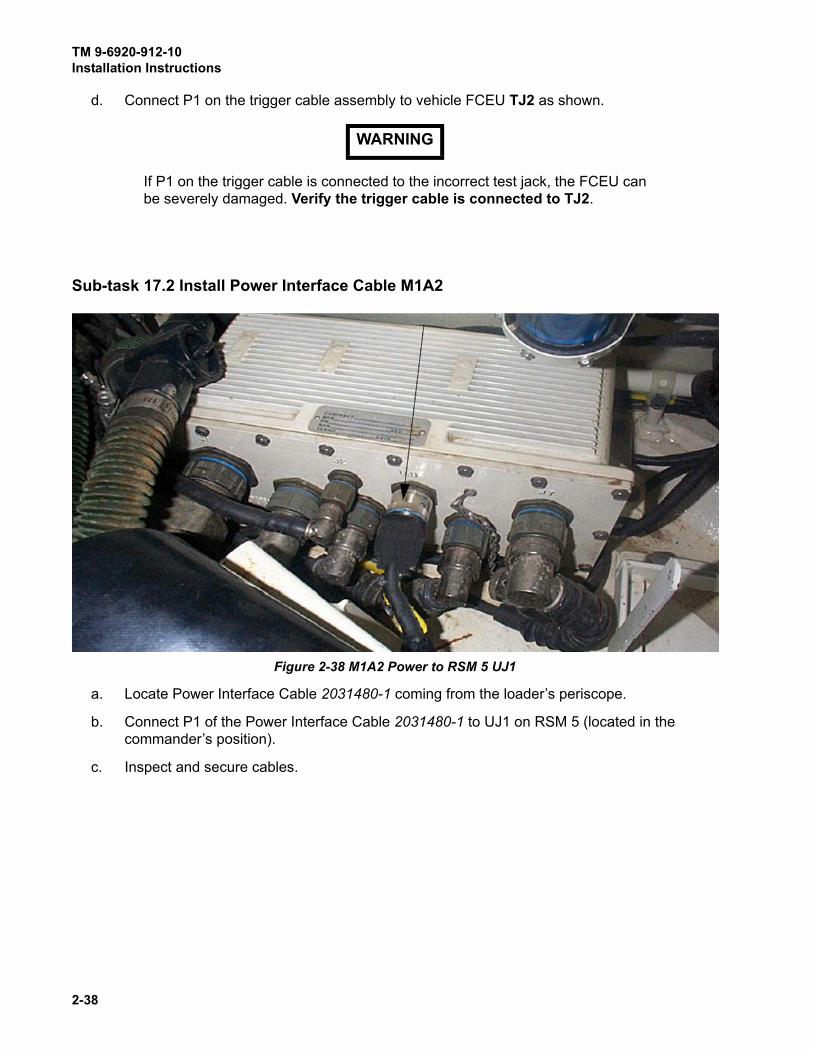
Sub-task 17.2 Install Power Interface Cable M1A2
a. Locate Power Interface Cable 2031480-1 coming from the loader’s periscope.
b. Connect P1 of the Power Interface Cable 2031480-1 to UJ1 on RSM 5 (located in the
commander’s position).
c. Inspect and secure cables.
WARNING
Figure 2-38 M1A2 Power to RSM 5 UJ1

TM 9-6920-912-10Installation Instructions
2-39
Sub-task 17.3 Install Power Interface Cable M1A2 SEP
NOTE
If vehicle has CROWS system installed, the Utility Jack shown will not provide
power. Proceed to Sub-task 17.4 for alternate MILES power connection for
CROWS equipped vehicles.
a. Locate Power interface cable 2031480-1 coming from the loaders periscope.
b. Connect P1 of the Power Interface Cable 2031480-1 to the auxiliary power connection (1)
(located under the commander’s Intercom box).
c. Inspect and secure cables.
Figure 2-39 M1A2 SEP Power to RSM 5 UJ1
1
TM 9-6920-912-10Installation Instructions
2-40
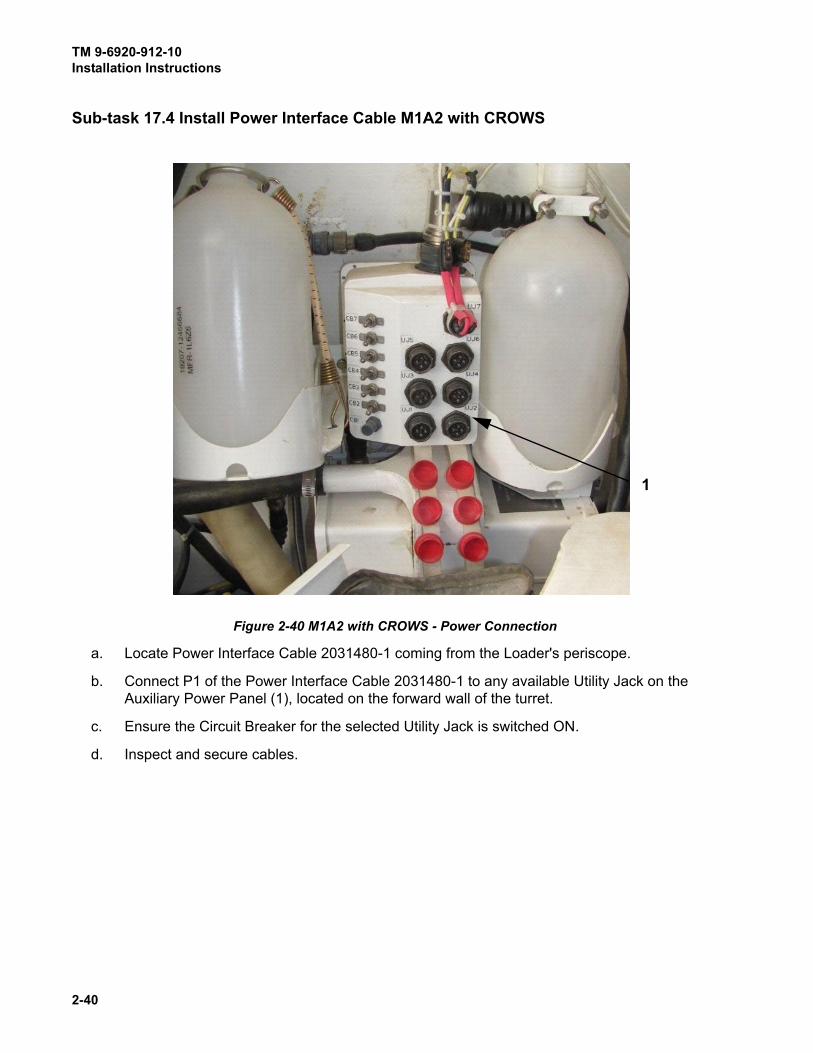
Sub-task 17.4 Install Power Interface Cable M1A2 with CROWS
Figure 2-40 M1A2 with CROWS - Power Connection
a. Locate Power Interface Cable 2031480-1 coming from the Loader's periscope.
b. Connect P1 of the Power Interface Cable 2031480-1 to any available Utility Jack on the
Auxiliary Power Panel (1), located on the forward wall of the turret.
c. Ensure the Circuit Breaker for the selected Utility Jack is switched ON.
d. Inspect and secure cables.
�
1
TM 9-6920-912-10Installation Instructions
2-41
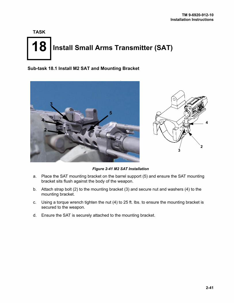
Sub-task 18.1 Install M2 SAT and Mounting Bracket
a. Place the SAT mounting bracket on the barrel support (5) and ensure the SAT mounting
bracket sits flush against the body of the weapon.
b. Attach strap bolt (2) to the mounting bracket (3) and secure nut and washers (4) to the
mounting bracket.
c. Using a torque wrench tighten the nut (4) to 25 ft. lbs. to ensure the mounting bracket is
secured to the weapon.
d. Ensure the SAT is securely attached to the mounting bracket.
TASK
18 Install Small Arms Transmitter (SAT)
2
Figure 2-41 M2 SAT Installation
4
23
3
4
2
5

TM 9-6920-912-10Installation Instructions
2-42
Sub-task 18.2 Install M240 SAT and Mounting Bracket
a. Open the clamp on the bracket by loosening the adjustment screw (1) and opening the
clamp handle.
b. Place the SAT clamp on the barrel and ensure the SAT is sitting level with the weapon, on
the right side of the barrel. The SAT bracket fits securely over the weapons front sight.
c. Close the clamp over the barrel and tighten the knob (1) with your fingers.
d. Secure the knob an additional 1/2 - 3/4 of a turn using the captive wrench (2). Slide the
captive wrench into the holding clip.
Figure 2-42 M240 SAT Installation
1

TM 9-6920-912-10Installation Instructions
2-43
NOTE
The captive wrench (2) on the M240 SAT is used to assist in tightening the
bracket onto the barrel. Do not tighten bracket more than 1/2 - 3/4 of a turn or
the SAT bracket may be damaged. The holding clip does nothing more than
hold the captive wrench into place on the SAT bracket (3).
e. Ensure the SAT is securely attached to the bracket assembly.
a. If a MGSS has been provided and installed, locate MGSS extension cable 2031482-1 and
connect P1 to VCU cable 2031438-2 P5.
b. Connect 2031482-1 P2 to MGSS connector J1.
Figure 2-43 Captive Wrench with Holding Clip
TASK
19 Install Main Gun Signature Simulator (MGSS) Cable
2
3

TM 9-6920-912-10Installation Instructions
2-44
a. If a DIFCUE has been provided and installed, locate DIFCUE extension cable 2031481-1
and connect P1 to VCU cable 2031438-2 P4.
b. Connect 2031481-1 P2 to DIFCUE connector J2.
TASK
20 Install Direct Indirect Fire CUE (DIFCUE) Cable
TM 9-6920-912-10Operating Instructions
3-1
CHAPTER 3OPERATING INSTRUCTIONS
SECTION I DESCRIPTION AND USE OF CVS CONTROLS AND INDICATORS
3.1 VEHICLE DISPLAY ASSEMBLY (VDA) CONTROLS AND INDICATORS
a. The VDA provides a 2-row by 16-character backlit display (1), two menu/submenu scroll
push-buttons (2) and one menu/submenu select push-button (3).
b. The display provides BIT results and event data that reinforce the audible cues provided by
the audio alarm (4) and RIA audio messages.
c. Any BIT failure, or lack of vehicle power, generates 5 beeps from the VDA and two beeps
through the vehicle intercom system. The VDA generates the following display when vehicle
power is not detected:
3.1.1 Visual Indicators
The VCU will flash on vehicles that have been engaged and signal that the vehicle is receiving
incoming fire. After being engaged by direct fire, an assessment message will be displayed on the
VDA. The event message will be displayed until a new event is received, or until any button is
pressed to clear it, returning to the previous display.
The VDA backlight will go out 7.5 secs after displaying a message. Thereafter it will take two button
presses to activate the display menus, with the first press of a button activating the backlight.
Figure 3-1 VDA Controls
N O V E H I C L E P OWE R
T O M I L E S
1
2
3
4
TM 9-6920-912-10Operating Instructions
3-2
3.1.2 Audio Messages
Audio indicators are voice messages heard through the vehicle intercom system. These messages
describe direct or indirect fire events that affects the status of the vehicle.
3.1.3 Built in Test (BIT)
The MILES XXI VCU contains a BIT program, which provides an indication of system status both
during initial start-up and operation. When power is first applied to the VCU, a BIT starts
automatically to check system electronics. BIT tests battery voltage, VCU computer, detector belts,
MGLT, FCI, RIA and VDA. BIT results are stored as event status data in the VCU memory and are
available for review in the event log via the VDA.
A manual BIT may also be initiated by scrolling to “SELECT AUX MENU” and pressing the
“SELECT” push-button. “SELECT BIT” will display. Press the “SELECT” push-button again.
“PRESS SELECT FOR BIT” will display, press the “SELECT” push-button to initiate BIT. A FAIL
message will appear on the display if BIT fails. Troubleshoot the system IAW Chapter 4.
NOTE
The system automatically runs a BIT every 15 minutes.
SECTION II OPERATION TASKS
NOTES
Before turning on power, ensure all installation tasks have been properly
completed. The MILES XXI is powered up once the MILES XXI VCU power
switch is turned on.
Turning ON power automatically starts BIT and the system goes to a KILL
state. Use the Controller Device (CD) to RESET/RESURRECT the vehicle.
Any generation MILES CD that sends a RESET/RESURRECT command can
be used.
The turret utility power must be turned ON from the CDU (M1A2 SEP), after
turning on turret power.
The turret utility power must be turned ON from the CID (M1A2), after
turning on turret power.
The turret utility power must be ON in order to fire the MILES LASER. If the
utility power is not ON, the vehicle will act as a non-firing target only.
TASK
1 Power Up and Start MILES XXI System BIT

TM 9-6920-912-10Operating Instructions
3-3
While in use, the MILES XXI system battery in the VCU is constantly being
charged when the vehicle turret utility power is ON.
a. Turn on HUTT and verify battery light “illuminates“ for 2 to 3 seconds.
NOTE
If battery light does not light up replace 9 volt battery and verify operation.
b. Power up the system and, once BIT has completed, the VDA will display a PASS or FAIL
message.
NOTE
The following is used as an example only.
::
(1) The following menu will be displayed if the system passes BIT.
:
NOTE
The display will show M1 but supports all variants of the Abrams tank.
c. If BIT receives a failure, an indication will be displayed in the display window and the
operator will have to scroll to the main menu to the “PRESS SELECT FOR EVENT STATUS” menu. Then press “SELECT” to determine where the failure lies by using the UP/DOWN scroll buttons.
d. If the following message is displayed in the VDA upon system start up, you can view the
event log to determine what device is missing.
(1) ## - denotes Event number.
(2) HHMMSS - denotes current Time.
(3) BIT FAIL - could display MISSING DEV, MISSING MOD, or DEV+MOD, depending on
which type of component was not detected. Troubleshoot the system IAW Chapter 4.
z To view the event log, scroll through the main menu using the UP/DOWNpush-buttons to the “PRESS SELECT FOR EVENT STATUS” menu,
press the “SELECT” push-button. :
WPN: MAINGUNM1 ALIVE
## HHMMSS BITFAIL - MISSING DEV
TM 9-6920-912-10Operating Instructions
3-4
z Scroll through the sub-menu until the missing device message is
displayed.
z In the above example, the DIFCUE is missing.
e. Set up the RIA for operation.
z Scroll the VDA to “SELECT AUX MENU” press the “SELECT” push-
button.
z Scroll to “SELECT VOLUME LEVEL” press the “SELECT” push-button.
z Use the UP/DOWN scroll push-buttons to set the “Volume 20%” initially.
It may be adjusted later according to user preference.
f. Set up Master Control Station (MCS).
z Use standard operating procedures for placing the MCS into operation.
a. Once the MILES XXI system is powered up and the BIT is complete, the first menu to appear
in the display will be the main menu. The main menu display allows the operator to view
various menus and to navigate within those menus. The following menus and sub-menus
will appear.
b. Using the UP/DOWN scroll push-buttons allows the operator to scroll through the main
menu and sub-menus. Use the “SELECT” push-button to enter each of the menu and or
sub-menu selections.
## HHMMSS DEVICEDIFCUE MISSING
TASK
2 Vehicle Display Assembly, (VDA) Menus
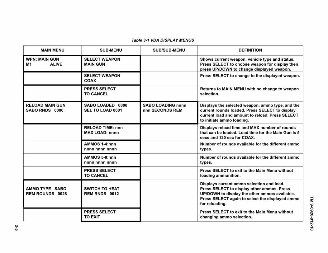
TM
9-6
92
0-9
12-1
0
3-5
Table 3-1 VDA DISPLAY MENUS
MAIN MENU SUB-MENU SUB/SUB-MENU DEFINITION
WPN: MAIN GUNM1 ALIVE
SELECT WEAPONMAIN GUN
Shows current weapon, vehicle type and status.Press SELECT to choose weapon for display thenpress UP/DOWN to change displayed weapon.
SELECT WEAPONCOAX
Press SELECT to change to the displayed weapon.
PRESS SELECT TO CANCEL
Returns to MAIN MENU with no change to weapon selection.
RELOAD MAIN GUNSABO RNDS 0000
SABO LOADED 0000SEL TO LOAD 0001
SABO LOADING nnnnnnn SECONDS REM
Displays the selected weapon, ammo type, and the current rounds loaded. Press SELECT to display current load and amount to reload. Press SELECT to initiate ammo loading.
RELOAD TIME: nnnMAX LOAD: nnnn
Displays reload time and MAX number of rounds that can be loaded. Load time for the Main Gun is 5 secs and 120 sec for COAX.
AMMOS 1-4:nnnnnnn nnnn nnnn
Number of rounds available for the different ammo types.
AMMOS 5-8:nnnnnnn nnnn nnnn
Number of rounds available for the different ammo types.
PRESS SELECT TO CANCEL
Press SELECT to exit to the Main Menu without loading ammunition.
AMMO TYPE SABOREM ROUNDS 0028
SWITCH TO HEATREM RNDS 0012
Displays current ammo selection and load. Press SELECT to display other ammos. PressUP/DOWN to display the other ammos available.Press SELECT again to select the displayed ammo for reloading.
PRESS SELECT TO EXIT
Press SELECT to exit to the Main Menu without changing ammo selection.

TM
9-6
92
0-9
12
-10
3-6
PRESS SELECT FOR EVENT STATUS
TIME - HHMMSS{PID#} IS ALIVE
Shows current time, vehicle PID and status.
{next most recent or previous event}
Pressing UP moves forward in time. Pressing DOWN moves back in time. Press SELECT to exit to the Main Menu or allow timeout (7.5 sec.)
SELECT AUX MENU Press SELECT to enter Aux Menu.Use the UP/DOWN to scroll through the submenus
SELECT BIT
PRESS SELECT FORBIT
Press SELECT for BIT function.Press SELECT to initiate BIT.Press SELECT again to exit to previous menu.
BACKLITE IS HIGHSELECT TO CHANGE
BACKLITE IS HIGHINC=UP DEC=DOWN
Starts with current BACKLITE level. Press UP to increase and press DOWN to decrease. Press SELECT to save setting and to exit.
SELECT VOLUME CONTROL
VOLUME: nn%USE UP/DOWN SW
Displays current intercom volume. Press UP/DOWN to increase and decrease volume. Press SELECT to save setting and to exit .
SELECT SOFTWARE VERSION
SELECT TO EXITSW VER XX.XX
Press SELECT to exit to previous menu.NOTE: Only displays VDA software version.
SELECT SYSTEM CONFIG
1234MLRCFS2++++++ +++++
Displays CVS module status. Press SELECT to exit to previous menu.
SELECT LEARN WEAPON
PRESS SELECT TO LEARN WEAPON
Press SELECT to access SAT Learning Function. Press SELECT again to initiate learn process for M2 or M240 SAT.
SELECT MAIN MENU
Press SELECT to exit to MAIN MENU.
Table 3-1 VDA DISPLAY MENUS (Continued)
MAIN MENU SUB-MENU SUB/SUB-MENU DEFINITION

TM
9-6
92
0-9
12
-10
3-7 Table 3-2 VDA Admin Menus
dfa
ADMIN MAIN MENU SUB-MENU SUB/SUB-MENU DEFINITION
ADMIN FUNCTIONSSELECT TO EXIT
Main menu of Admin Functions Menu structure. SELECT exits to main Menus. Scroll Up or Down and SELECT Sub-menu functions.
SELECT TO CHOOSE VEHICLE TYPE
SELECT VEHICLE TYPE OF xxxxxx
SELECT CONFIRMS TYPE xxxxxx
Scroll UP/DOWN to display vehicle types. SELECTto choose. Press SELECT again to confirm or UP/DOWN to abort.
SELECT LEARN WEAPON
PRESS SELECT TO LEARN WEAPON
Press SELECT to access SAT Learning Function.Press SELECT again to initiate learn process forM2 or M240 SAT.
SELECT TO SET VEHICLE PID
UP/DOWN/SELECT TO SET PID nnnn
SELECT CONFIRMS SET PID TO nnnn
Scroll UP/DOWN to set each PID digit. SELECT for next digit. Press SELECT again to confirm or UP/DOWN to abort.
SELECT TO CHOOSE DCI MODE
SELECT TO SET DCI MODE TO xxx
SELECT CONFIRMS SET TO DCI xxx
Scroll UP/DOWN to display ON or OFF. SELECT to choose. Press SELECT again to confirm.
SELECT TO CHOOSE FIRE MODE
PRESS SELECT FOR xxxxx FIRE MODE
SELECT CONFIRMS xxxxx FIRE MODE
Scroll UP/DOWN to display DRY or BLANK. SELECT to choose. Press SELECT again to confirm or UP/DOWN to abort.
SELECT FOR BELT CONFIG
SELECT TO CONFIG BELT n
SHOOT RESET AT BELT n mm SEC
Scroll UP/DOWN to display belt to configure. SELECT to choose. Using CD, shoot RESET at belt to be configured within 30 seconds or UP/DOWN to abort.
SELECT TO SHOW SYSTEM CONFIG
1234 MLRCV++++++++++
SELECT to show CVS System Configuration display. Press SELECT again to exit.
SELECT TO CLEAR EVENT LOG
SELECT CONFIRMS CLEAR EVENT LOG
SELECT to Clear Event Log. Press SELECT again to confirm or UP/DOWN to abort.

TM 9-6920-912-10Operating Instructions
3-8
NOTES
Check vehicle config and if required perform one of the following procedures.
Either procedure can be utilized to configure the vehicle. However, Sub-task
3.2 requires the use of a MILES XXI Controller Device (CD).
Sub-task 3.1 Configure Vehicle Using the VDA
a. With the system powered up, check the VDA display to confirm the vehicle is configured
correctly (configured as an “M1”).
(1) The vehicle type will be displayed in the stet left hand corner of the display window.
b. If the vehicle needs to be reconfigured, do the following steps.
c. Use a CD to fire the “CTRL ON” command (or a MILES Code 35, PID 315) at any detector
belt.
d. “ADMIN FUNCTIONS” is displayed on the VDA.
e. Scroll down to “SELECT TO CHOOSE VEHICLE TYPE” menu.
f. Press “SELECT” and scroll to select the appropriate vehicle.
g. Press “SELECT” and a display similar to the following will appear:
h. If the vehicle type shown is the one desired, press “SELECT” to activate it. If incorrect, press
UP or DOWN to abort this function.
i. When the vehicle type has changed, an “INITIALIZED” voice cue sounds through the
vehicle intercom system.
Sub-task 3.2 Configure Vehicle Using a MILES XXI Controller Device (CD)
NOTE
This Sub-task is an alternate for Sub-task 3.1, and can only be performed if a
MILES XXI Controller Device is available.
TASK
3 Vehicle Configuration
SELECT CONFIRMSTYPE M1

TM 9-6920-912-10Operating Instructions
3-9
a. With the system powered up, check the VDA display to confirm the vehicle is configured
correctly (configured as an M1).
(1) The vehicle type will be displayed in the lower left hand corner of the display window on
the Main Menu.
b. If the vehicle needs to be reconfigured do the following steps.
c. Use the CD to acquire the VCU via RF: Scroll thru the CD menus to the “CD FUNCTIONS MENU”. Pull the trigger and scroll to the “CD ACQUIRE MENU”. Point the CD at a detector
and pull the trigger. The VDA beeps twice. CD will display the acquired PID of the VCU.
Check the VDA to insure the PID matches the PID acquired.
d. To reconfigure the vehicle type using the CD, scroll through the menus and locate the “CVS MENU” menu. Once located, pull the trigger.
e. In the “CVS MENU”, scroll to select the “CVS SET VEHICLE CFG” menu.
f. In the “CVS SET VEHICLE CONFIG” menu, pull the trigger and scroll to select the
appropriate vehicle (M1).
NOTE
If the following menu appears “NO VEHICLE TABLE AVAILABLE INMEMORY”, conduct the following procedures.
(1) Scroll to the “CVS REQ VEHICLE CFG” sub-menu and pull the trigger.
(2) The following sub-menu will be displayed, “IMPORTING LIST”.
(3) Once the list has been imported from the VCU, the following sub-menu will be displayed
“IMPORT COMPLETE”.
(4) Importing the vehicle list is complete, continue conducting vehicle configuration.
g. Within the “CVS SET VEHICLE CFG” menu, pull the trigger and scroll to select the
appropriate vehicle (M1).
h. Once the vehicle has been selected, pull the trigger to send the RF command and confirm
the vehicle selected is displayed on the VDA display window. The CD will display:
i. If the system does not configure properly, repeat Steps c. - f.
VEHICLE RESPONSEVEHICLE NUMBER: NNVEHICLE ID: AAAAAA
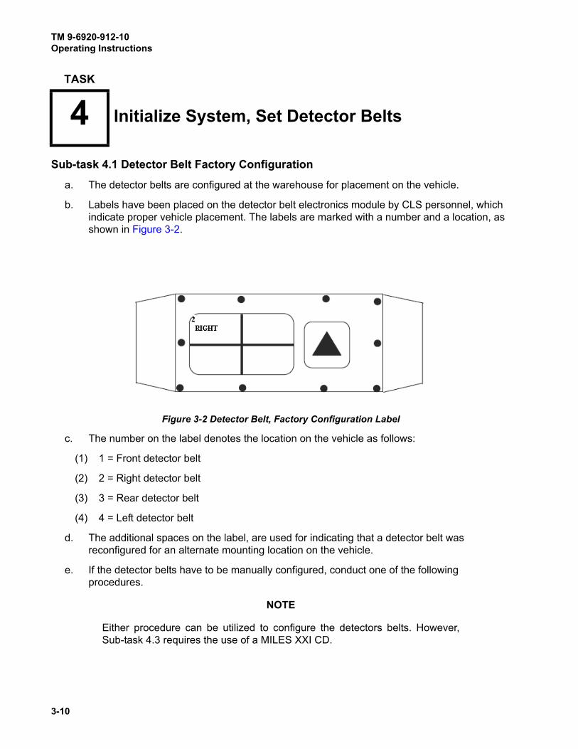
TM 9-6920-912-10Operating Instructions
3-10
Sub-task 4.1 Detector Belt Factory Configuration
a. The detector belts are configured at the warehouse for placement on the vehicle.
b. Labels have been placed on the detector belt electronics module by CLS personnel, which
indicate proper vehicle placement. The labels are marked with a number and a location, as
shown in Figure 3-2.
c. The number on the label denotes the location on the vehicle as follows:
(1) 1 = Front detector belt
(2) 2 = Right detector belt
(3) 3 = Rear detector belt
(4) 4 = Left detector belt
d. The additional spaces on the label, are used for indicating that a detector belt was
reconfigured for an alternate mounting location on the vehicle.
e. If the detector belts have to be manually configured, conduct one of the following
procedures.
NOTE
Either procedure can be utilized to configure the detectors belts. However,
Sub-task 4.3 requires the use of a MILES XXI CD.
TASK
4 Initialize System, Set Detector Belts
Figure 3-2 Detector Belt, Factory Configuration Label
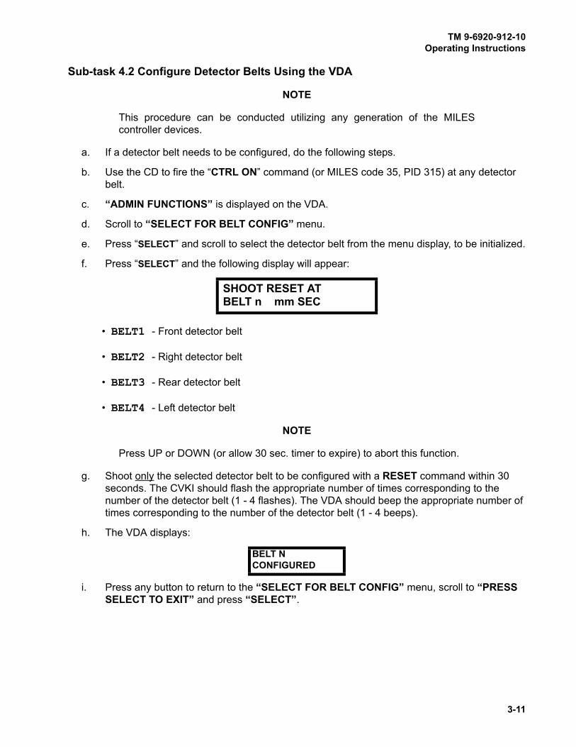
TM 9-6920-912-10Operating Instructions
3-11
Sub-task 4.2 Configure Detector Belts Using the VDA
NOTE
This procedure can be conducted utilizing any generation of the MILES
controller devices.
a. If a detector belt needs to be configured, do the following steps.
b. Use the CD to fire the “CTRL ON” command (or MILES code 35, PID 315) at any detector
belt.
c. “ADMIN FUNCTIONS” is displayed on the VDA.
d. Scroll to “SELECT FOR BELT CONFIG” menu.
e. Press “SELECT” and scroll to select the detector belt from the menu display, to be initialized.
f. Press “SELECT” and the following display will appear:
• BELT1 - Front detector belt
• BELT2 - Right detector belt
• BELT3 - Rear detector belt
• BELT4 - Left detector belt
NOTE
Press UP or DOWN (or allow 30 sec. timer to expire) to abort this function.
g. Shoot only the selected detector belt to be configured with a RESET command within 30
seconds. The CVKI should flash the appropriate number of times corresponding to the
number of the detector belt (1 - 4 flashes). The VDA should beep the appropriate number of
times corresponding to the number of the detector belt (1 - 4 beeps).
h. The VDA displays:
i. Press any button to return to the “SELECT FOR BELT CONFIG” menu, scroll to “PRESS SELECT TO EXIT” and press “SELECT”.
SHOOT RESET ATBELT n mm SEC
BELT NCONFIGURED

TM 9-6920-912-10Operating Instructions
3-12
j. Scroll up until you find the “SELECT TO SHOW SYSTEM CONFIG” display.
k. Press “SELECT.” The display will display the following:
Figure 3-3 “SYSTEM CONFIG” Display
• 1-4 - denotes the total number of belts defined for the configured vehicle.
• M - denotes MGLT.
• L - denotes VDA.
• R - denotes RIA (Intercom Interface).
• C - denotes CVKI CONTROLLER.
• F - denotes FCI.
• S - denotes M240 SAT.
• 2 - denotes M2 SAT
l. All items highlighted with an “+” denote the VCU has recognized those components
connected within the system configuration. A “-” indicates that the component has not been
recognized in the configuration of the vehicle kit. Additionally, the VDA will display a “-” for
any component that fails during operations.
NOTES
Confirmation of the system config should be conducted initially after the
completion of BIT.
If the vehicle cannot be configured refer to paragraph 4.4.1 (System
Configuration Troubleshooting).
A “D” may be shown as the last character in the SYSTEM CONFIG display if
the MILES XXI has been configured for use in Instrumented Mode. See Task 8
for instrumented mode configuration.
Sub-task 4.3 Configure Detector Belts Using the MILES XXI Controller Device
NOTE
This Sub-task is an alternate for Sub-task 4.2, and can only be performed if a
MILES XXI Controller Device is available.
1 2 3 4 M L R C F S 2
+ + + + + + + + + + +
TM 9-6920-912-10Operating Instructions
3-13
a. If a detector belt needs to be configured, perform the following steps.
b. Using the MILES XXI CD, pull the trigger to power it on. Using the UP/DOWN scroll push-
buttons, select the “CVS MENU” from the list of menus and pull the trigger.
c. In the CVS menu, select the “CVS BELT1 CMD IR” and beginning with the front detector
belt, fire the CD at the detector belt using the “CVS BELT1 CMD IR”. Ignore the CVKI
flashes at this time.
d. While standing in front of the vehicle, move in a clockwise manner around the vehicle and
fire the CD at each belt with the corresponding command. For example the next belt, you
would select “CVS BELT2 CMD IR”, then 3 and 4.
• BELT1 - Front detector belt
• BELT2 - Right detector belt
• BELT3 - Rear detector belt
• BELT4 - Left detector belt
e. Continue until all four detector belts have been fired at.
f. Once the detector belts have been fired at, conduct the following procedures.
g. Turn VCU power OFF and back ON again.
h. Using the CD, RESET the vehicle to an ALIVE status.
i. In the CVS menu, select the “CVS BELT1 CMD IR” and beginning with the front detector
belt, fire the CD at the detector belt using the “CVS BELT1 CMD IR”. The CVKI should
flash the appropriate number of times corresponding to the number of the detector belt (in
this case 1 flash). The VDA should beep the appropriate number of times corresponding to
the number of the detector belt (in this case 1 beep).
j. While standing in front of the vehicle, move in a clockwise manner around the vehicle and
fire the CD at each belt with the corresponding command. For example the next belt, you
would select “CVS BELT2 CMD IR”, then 3 and 4. The CVKI should flash the
appropriate number of times corresponding to the number of the detector belt (2 - 4 flashes).
The VDA should beep the appropriate number of times corresponding to the number of the
detector belt (2 - 4 beeps).
k. Scroll through the VDA main menus and select “SELECT AUX MENU” from the VDA
display.
l. Scroll through the “SELECT AUX MENU” sub-menus until you find the “SELECT SYSTEM CONFIG” display.

TM 9-6920-912-10Operating Instructions
3-14
m. Select “SELECT SYSTEM CONFIG” sub-menu and the display will display the following
text:
Figure 3-4 “SYSTEM CONFIG” Display
• 1-4 - denotes the total number of belts expected for the current vehicle.
• M - denotes MGLT.
• L - denotes VDA.
• R - denotes RIA.
• C - denotes CVKI CONTROLLER.
• F - denotes FCI.
• S - denotes M240 SAT.
• 2 - denotes M2 SAT.
n. All items highlighted with an “+” denote the VCU has recognized those components
connected within the system configuration. A “-” indicates that the component has not been
recognized in the configuration of the vehicle kit. Additionally, the VDA will display a “-“ for
any component that fails during operations.
NOTES
Confirmation of the system config should be conducted initially after the
completion of BIT.
If the vehicle cannot be configured refer to paragraph 4.4.1 (System
Configuration Troubleshooting).
A “D” may be shown as the last character in the SYSTEM CONFIG display if
the MILES XXI has been configured for use in Instrumented Mode. See Task 8
for instrumented mode configuration.
1 2 3 4 M L R C F S 2
+ + + + + + + + + + +

TM 9-6920-912-10Operating Instructions
3-15
NOTE
Either procedure can be utilized to set the vehicle PID. However, Sub-task 5.2
requires the use of a MILES XXI CD.
Sub-task 5.1 Set Vehicle PID Using the VDA
a. Use a CD to fire the “CTRL ON“ command (or MILES code 35, PID 315) at any detector belt.
b. “ADMIN FUNCTIONS” is displayed on the VDA.
c. Scroll to select the “SELECT TO SET VEHICLE PID” menu.
d. Press “SELECT” and the following display will appear:
e. Press the UP/DOWN push-buttons to select the first number of the PID, press the “SELECT”
push-button to continue.
f. Continue the procedure above (step e.), for the remaining three digits. When the last digit is
entered and the “SELECT” push-button is pressed, the VDA will display the screen below.
g. Press “SELECT“ to confirm the setting. The VDA will beep twice and the display will show
the new PID.
NOTE
Pressing UP or DOWN will abort this function.
Sub-task 5.2 Set Vehicle PID Using the MILES XXI Controller Device (CD)
NOTE
This Sub-task is an alternate for Sub-task 5.1, and can only be performed if a
MILES XXI Controller Device is available.
a. Use the CD to link to the VCU via RF. Scroll thru the CD menus to the “CD FUNCTIONS MENU”. Pull the trigger and scroll to the “CD ACQUIRE MENU”. Point the CD at a detector
TASK
5 Set Vehicle Player Identification (PID)
UP/DOWN/SELECT
TO SET PID - - - -
SELECT CONFIRMSSET PID TO XXXX

TM 9-6920-912-10Operating Instructions
3-16
belt and pull the trigger. The VDA beeps twice. The CD will display the acquired PID of the
VCU. Check the VDA to insure the PID matches the PID acquired.
b. To change the vehicle PID using the CD, scroll through the menus and locate the “PID MENU” menu. Once located, pull the trigger.
c. Scroll to select the “PID SELECT” menu.
d. In the “PID SELECT” menu, pull the trigger and scroll using the UP/DOWN push-buttons
to select the first digit of the PID, then press the SEL push-button to continue.
e. Continue selecting the other three digits using the UP/DOWN push-buttons. Press the SEL
push-button each time to progress to the next digit.
f. When the last digit is entered, the following the menu will appear on the CD: “PID SEND”.
g. Pull the trigger to send the RF command to the VCU. Confirm the PID is displayed on the
VDA display window.
h. Setting the vehicle PID using the CD is complete.

TM 9-6920-912-10Operating Instructions
3-17
Figure 3-5 Detector Belt Testing
a. Ensure vehicle master power is ON.
b. Ensure that all cable connections to the detector belts and VCU are secure.
c. Obtain a Controller Device (CD) to test your detector belts. Fire a NEAR MISS code (Heavy
Near Miss, MILES Code 28) at each detector from a distance of 3 to 10 feet.
d. Each time the CD fires, the VCU should flash 2 times and the VCI will alert with a NEAR MISS message.
NOTE
A belt segment is serviceable if ONE detector is bad.
e. If more than one detector per belt segment fails the test (VCU does not flash), perform
troubleshooting per Chapter 4, Table 4-2 (TROUBLESHOOTING) of this manual.
This optional task describes the MILES XXI capability to select the fire mode
(Blank Fire or Dry Fire) of the simulated vehicle weapons. The selected fire
mode will apply to all vehicle weapons (COAX, TOW, M2, M240) except the
Main Gun, which is always in dry fire mode.
TASK
6 Test Detector Belts
TASK
7 Select Weapon Fire Mode (Optional)

TM 9-6920-912-10Operating Instructions
3-18
a. Use a CD to fire the “CTRL ON“ command (or MILES code 35, PID 315) at any detector belt.
b. “ADMIN FUNCTIONS“ is displayed on the VDA
c. Scroll down to “SELECT TO CHOOSE FIRE MODE“and press SELECT.
d. The following is displayed on the VDA:
or
e. Use the UP/DOWN buttons to display the desired mode, then press SELECT to display the
confirmation screen:
NOTE
If the Fire Mode displayed is not the one desired, press UP or DOWN to abort
this function.
f. Exit to the main menu by pressing SELECT from:
g. Confirm the fire mode setting for all installed weapons (except MAIN GUN) on the main
menu. “DRY“ will be displayed after the weapon name as shown below. No text after the
weapon name indicates Blank Fire Mode.
PRESS SELECT FOR BLANK FIRE MODE
PRESS SELECT FOR DRY FIRE MODE
SELECT CONFIRMS BLANK FIRE MODE
ADMIN FUNCTIONS SELECT TO EXIT
WPN: COAX DRYM1 ALIVE

TM 9-6920-912-10Operating Instructions
3-19
This optional task describes the MILES XXI capability to select the
instrumented mode of the the vehicle operations. When the DCI mode is ON,
the CVS system will expect an instrumentation package attached to the P2
connector of the VCU cable at J3.
a. Use a CD to fire the “CTRL ON” command (or MILES code 35, PID 315) at any detector belt.
b. “ADMIN FUNCTIONS” is displayed on the VDA.
c. Scroll down to “SELECT TO CHOOSE DCI MODE” and press SELECT.
d. The following is displayed on the VDA:
or
e. Use the UP/DOWN buttons to display the desired mode, then press SELECT to display the
confirmation screen:
f. Press SELECT to confirm the selection.
NOTE
If the DCI mode displayed is not the one desired, press UP or DOWN to abort
this function.
g. To verify DCI operation, scroll to “SELECT TO SHOW SYSTEM CONFIG” (or “SELECT SYSTEM CONFIG” in the main menu). The display will include a “D” when DCI mode is
“ON”. If the MILES XXI system is in communication wIth the instrumentation package, a “+”
will be displayed below the “D” otherwise a “-” will be shown.
TASK
8 Select DCI Mode (Optional)
SELECT TO SETDCI MODE TO ON
SELECT TO SET DCI MODE TO OFF
SELECT CONFIRMSSET DCI ON
TM 9-6920-912-10Operating Instructions
3-20
NOTE
Blank ammunition is not required for dry fire vehicle configuration.
a. Load the Coax machine gun with blank ammunition.
b. Refer to the Operator’s Manual for loading procedures.
a. Ensure tank is parked on level ground.
b. Ensure MILES XXI equipment has been properly installed and configured for the M1A1.
c. Turn on Vehicle Power
(1) Master Power ON
(2) Turret Power ON
(3) Turret Utility Power (on TNB) ON
d. Prepare gunner’s station for operation. (Refer to TM 9-2350-264-10-2)
NOTE
Record zero data for future reference.
e. Set FIRE CONTROL MODE switch to MANUAL and perform the following:
(1) Set THERMAL MODE switch to STBY.
(2) Clear main gun.
(3) Clear coax machine-gun.
(4) Clear loader’s machine-gun.
(5) Clear tank commander’s machine-gun.
f. Set up target at 1200 meters.
TASK
9 Load Coax Machine Gun
TASK
10 M1A1 Alignment Procedures

TM 9-6920-912-10Operating Instructions
3-21
NOTE
Alignment will require use of the fire control system in NORMAL mode for
certain steps. When hydraulic pressure drops below 1500 psi, NORMAL mode
operation can be erratic.
g. With engine running, ensure turret hydraulic pressure reads between 1500-1700 psi.
h. Set GUN SELECT switch to MAIN.
i. Set MAGNIFICATION lever to 10X.
j. Make sure FLTR/CLEAR/SHTR switch is set to CLEAR.
k. Make sure ballistic doors are open.
l. Set FIRE CONTROL MODE switch to EMERGENCY, squeeze gunner’s palm switches and
check for drift. Observe for 20 seconds, if rate of drift exceeds 0.5 mil per second-Notify unit
maintenance.
m. Set FIRE CONTROL MODE switch to NORMAL.
n. Open CCP door and turn on CCP.
(1) Press WIND key and enter 0.0, leave lit.
(2) Press CANT key and enter 0.0, leave lit.
(3) Press LEAD key and enter 0.0, leave lit.
(4) Select SABOT, Press AMMO SUBDES enter 59 press ENTER key.
(5) Select HEAT, Press AMMO SUBDES enter 59 press ENTER key.
(6) Select COAX, Press AMMO SUBDES enter 59 press ENTER key.
(7) Press RANGE key and enter 1200 (RANGE TO BORESIGHT TARGET).
(8) Press ENTER key.
(9) Depress Gunner’s or Commander’s Palm Switch. This induces the range.
o. Set FIRE CONTROL MODE switch to MANUAL.
p. Select COAX.
q. Press BORESIGHT on the CCP and enter MAIN GUN MILES BORESIGHT READINGS
and push ENTER.
r. Press ZERO on the CCP and enter 0.0, 0.0 and push ENTER.
s. Select SABOT.
t. Press ZERO on the CCP and enter 0.0, 0.0 and push ENTER.
u. Have gunner move day reticle to an alignment aiming point. (GUNNER USES THE MANUAL TRAVERSE AND ELEVATION TO MOVE THE GUN TO THE ALIGNMENT AIMING POINT).

TM 9-6920-912-10Operating Instructions
3-22
Figure 3-6 MGLT Locking Knobs and Alignment Knobs
v. Unlock the elevation and azimuth knobs on the MGLT (refer to Appendix C). Have the
Loader look through the 12X scope on the MGLT. Use azimuth and elevation alignment
knobs to adjust the MGLT to the vehicles alignment aiming point. Lock down azimuth and
elevation locking knobs.
w. Verify that MGLT has not moved from alignment point when locked down. If necessary,
readjust with necessary offset, so that MGLT is accurately aligned after the azimuth and
elevation locking knobs are secure.
x. Using MANUAL controls move the gun off target and re-lay back on target using a G pattern
and verify the aiming point of the SIGHTS and the MGLT are the same.
y. Refer the Thermal sight to the aiming point.
z. Refer the GAS sight to the aiming point.
aa. Set FIRE CONTROL MODE switch to NORMAL and verify alignment of all sights to the
MGLT.
ab. Fire at a MILES target with the MAIN GUN and COAX to confirm Alignment.
NOTE
See TASKS 12 and 13 for procedures on firing main gun and coax.
Elevation
Azimuth
Locking KnobsElevation
Azimuth
Alignment Knobs
(not visible)

TM 9-6920-912-10Operating Instructions
3-23
a. Place tank on level platform with target placed at 1200 meters.
b. Ensure MILES XXI has been properly installed and configured for M1A2.
c. Turn on MILES XXI Power.
d. Turn on Master Power.
e. Turn on Turret Power.
CID INPUTS
a. Turn on Turret Utility Power UJ1.
(1) From the CID "SELECT" Pre Post
(2) "SELECT" Aux Systems
(3) "SELECT" Aux Controls
(4) Place “TUR UTIL” to ON
GDCP INPUTS
a. On the GDCP “SELECT" Adjust.
b. "SELECT" SABOT Ammunition.
c. "SELECT" AMMO Subdes.
(1) Using UP/DOWN toggle switch "SELECT" MILES on GDCP and "SELECT" ENT on
Keypad
d. "SELECT" HEAT Ammunition.
e. "SELECT" AMMO Subdes.
(1) Using up/down toggle switch "SELECT" MILES on GDCP and "SELECT" ENT on
Keypad
f. "SELECT" COAX Ammunition.
g. "SELECT" AMMO SUBDES.
(1) Using up/down toggle switch "SELECT" MILES on GDCP and "SELECT" ENT on
Keypad
(2) Return to MAIN MENU
TASK
11 M1A2 Alignment Procedures
TM 9-6920-912-10Operating Instructions
3-24
h. "SELECT" METRL DATA.
i. "SELECT" CROSSWIND.
(1) "SELECT" Manual
(2) "SELECT" 0000 and ENT on Keypad
(3) Return to MAIN MENU
j. "SELECT" SENSORS.
k. "SELECT" ATTD.
(1) "SELECT" Pitch and Roll to select OFF
l. "SELECT" CANT.
(1) "SELECT" Manual Mode and "SELECT" ENT on keypad
(2) Return to MAIN MENU
m. "SELECT" LEAD.
(1) "SELECT" Manual
(2) "SELECT" ENT on keypad
(3) Return to MAIN MENU
n. Select target Alignment Aiming Point.
o. Lay main gun on Alignment Aiming Point.
p. Refer to Figure 3-6 (MGLT Locking Knobs and Alignment Knobs). Unlock the elevation and
azimuth knobs on the MGLT. Have the Loader look through the 12X scope on the MGLT. Use
azimuth and elevation adjustment knobs to move the MGLT to vehicles alignment aiming
point. Lock down azimuth and elevation locking knobs.
q. Verify that MGLT has not moved from alignment point when locked down. If necessary,
readjust with necessary offset, so that MGLT is accurately aligned after the azimuth and
elevation locking knobs are secure.
r. Using MANUAL controls move the gun off target and relay back on target using a G pattern
and verify the aiming point of the SIGHTS and the MGLT are the same.
s. Refer the Thermal sight to the aiming point.
t. Refer the CITV to the aiming point.
u. Refer the GAS sight to the aiming point.
v. Set FIRE CONTROL MODE switch to NORMAL, and verify alignment of all sights to the
MGLT.
w. Fire at a MILES target with the MAIN GUN and COAX to confirm Alignment.
x. See TASKS 12 and 13 for procedures on firing main gun and coax.

TM 9-6920-912-10Operating Instructions
3-25
a. Load all small arms with blank ammunition.
b. Refer to the appropriate Operator’s Manual for loading procedures.
Sub-task 12.1 Main Gun Ammunition Reload
NOTES
The following procedures pertain to both MAIN GUN and COAX loading
procedures. Load times are 5 second for the MAIN GUN and 20 seconds for
COAX.
The displayed ammo type and rounds counts will vary from the examples
shown below, based on user selection and actual ammo levels.
a. To select weapon type press “SELECT” while in the main menu (below):
(1) Scroll through the sub-menus to select the weapon type.
b. From the main menu, scroll to view weapon basic load and rounds remaining (below), and
press “SELECT”.
(1) Scroll through the sub-menus to view the ammunition types. Press the “SELECT” push-
button to select the ammunition to be loaded.
TASK
12 Load Vehicle Weapons
WPN: MAIN GUNM1 ALIVE
SELECT WPNTYPEMAIN GUN
SELECT WPNTYPECOAX
AMMO TYPE SABOREM RNDS 0023

TM 9-6920-912-10Operating Instructions
3-26
c. Once the ammunition is selected the VDA will return to the main menu.
d. To load ammunition, scroll to the Reload menu (below) and press “SELECT”.
e. If a round of the selected ammo is currently loaded, the following menu will appear.
f. If the round needs to be loaded the following menu will appear.
g. Press the “SELECT” push-button and the following menu will appear.
h. Once the round has loaded, the display will return to the Reload menu shown in step d.
Loading sequence complete.
SELECT SABOREM RNDS 0023
SELECT HEATREM RNDS 0012
RELOAD MAIN GUNSABO RNDS 0001
SABO LOADED 0001FULL LOAD
SABO LOADED 0000SEL TO LOAD 0001
SABO LOADING 0001005 SECONDS REM
TM 9-6920-912-10Operating Instructions
3-27
Sub-task 13.1 Test Fire Main Gun
a. Arm main gun and fire at another MILES equipped vehicle or target to ensure the MGLT is
functioning properly.
b. If a Hit, Kill, or Near Miss is achieved, the MGLT is functioning properly.
NOTE
Periodically clean the MGLT lens with a clean, soft cloth to prevent the
transmitter from firing erratically due to residue/dust build-up.
Sub-task 13.2 Test Fire M2 Machine Gun
a. Fire a 10 - 15 round burst from the machine gun.
b. Fire the machine gun at a target (vehicle or manworn system), to ensure the SAT is
functioning properly.
c. If a Kill or Near Miss is achieved the SAT is functioning properly.
d. Place weapon on SAFE and check to ensure the BFA and SAT remain securely attached.
NOTE
Periodically clean weapon with oil and a clean cloth. Residue buildup will
occur more rapidly firing blank ammunition. Clean transmitter with a soft cloth
after every 500 rounds fired or as often as possible to prevent the transmitter
from firing erratically due to residue buildup.
Sub-task 13.3 Test Fire M240 Machine Gun
a. Fire a 20 - 30 round burst from the machine gun.
b. Fire the machine gun at a target (manworn system), to ensure the SAT is functioning
properly.
c. If a Kill or Near Miss is achieved the SAT is functioning properly.
d. Place weapon on SAFE and check to ensure the BFA and SAT remain securely attached.
NOTE
Periodically clean weapon with oil and a clean cloth. Residue buildup will
occur more rapidly firing blank ammunition. Clean transmitter with a soft cloth
after every 500 rounds fired or as often as possible to prevent the transmitter
from firing erratically due to residue buildup.
TASK
13 Test Fire Weapons
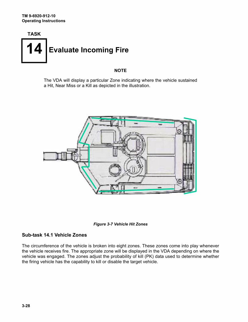
TM 9-6920-912-10Operating Instructions
3-28
NOTE
The VDA will display a particular Zone indicating where the vehicle sustained
a Hit, Near Miss or a Kill as depicted in the illustration.
Sub-task 14.1 Vehicle Zones
The circumference of the vehicle is broken into eight zones. These zones come into play whenever
the vehicle receives fire. The appropriate zone will be displayed in the VDA depending on where the
vehicle was engaged. The zones adjust the probability of kill (PK) data used to determine whether
the firing vehicle has the capability to kill or disable the target vehicle.
TASK
14 Evaluate Incoming Fire
Figure 3-7 Vehicle Hit Zones
TM 9-6920-912-10Operating Instructions
3-29
The purpose of the MILES XXI system is to realistically simulate force on force weapons training.
When direct fire “hits” the vehicle, the system performs 3 distinct functions:
• Evaluate When the system detects direct fire LASER beams, the VCU evaluates the
effects of that event based on a number of factors such as the vulnerability
of the vehicle, the type of weapon, and where a direct fire HIT occurred and
then determines whether the vehicle receives a NEAR MISS, HIT, or KILL.
• Signal Each VCU has a CVKI, which flashes when the vehicle receives a NEARMISS, HIT, or KILL so the crew and others in the training area can see the
effects of incoming fire on vehicle.
The system inserts voice messages into the vehicle intercom so the crew
members can hear the effects to the vehicle.
When connected, the DIFCUE will fire to present the indication that a kill
occurred.
• Disable To simulate damage, the system affects some vehicle functions for
example:
z COMMUNICATIONS KILL requires you to stop
using the radios. For safety reasons
communications are not actually disabled.
z FIREPOWER KILL disables all vehicle weapons
from firing the LASER transmitter.
z After receiving a MOBILITY KILL, the crew has 20
seconds to stop vehicle movement. After 20
seconds the vehicle position is recorded in the VCU
and if the vehicle is moved more than 100 meters,
the system will initiate a Cheat Kill.
z If you attempt to move the vehicle after a MOBILITYKILL, the system initiates a CATASTROPHIC KILL,that will be recorded in the event memory as a
CHEAT KILL.

TM 9-6920-912-10Operating Instructions
3-30
Sub-task 14.2 Effects of Incoming Fire
The vehicle can be KILLED, HIT, or NEAR MISSED by opposing direct fire. When the MILES XXI
system detects a LASER engagement the VCU evaluates the effects of the event and decides if the
vehicle is KILLED, received a FIREPOWER KILL, COMMUNICATIONS KILL, MOBILITY KILL, HITno damage, or NEAR MISS.
NOTE
A combination of a Firepower Kill and a Mobility Kill will produce a
Catastrophic Kill. Combinations of Mobility Kill, Firepower Kill, and
Communications Kill are possible.
The visual message on the Vehicle Display Assembly (VDA) will display the
attackers weapon code, zone and PID. The attacking weapons codes and
event time are stored in the events list. This event information is stored in the
VCU and downloaded after the exercise is complete. This data is used to
develop the After Action Review (AAR).
Each of these “receiving fire” assessment events will be displayed in the VDA
display until “acknowledged” by pressing any VDA button, or until it is
overwritten by a new event. Following the event, you will receive voice
messages over the vehicle intercom identifying the event.
• KILL There are five types of KILLS:
z CATASTROPHIC KILL - This simulates
damage that destroys the vehicle and kills its
occupants.
z FIREPOWER KILL - Simulates a hit that
knocks out the vehicles weapon systems.
z MOBILITY KILL - Causes you to stop vehicle
movement.
z COMMUNICATIONS KILL - Requires you to
stop using vehicle radios.
z CHEAT KILL - If you attempt to move your
vehicle after receiving a Mobility Kill, or tamper
with/disconnect MILES XXI components, the
system will present a Catastrophic Kill on the
VDA and display a Cheat Kill in the event log
memory.
• HIT Causes no vehicle damage.
• NEAR MISS Indicates incoming fire that hits close to the vehicle but does not hit
the vehicle itself or cause any damage. Take evasive action and return
fire or move to another position.
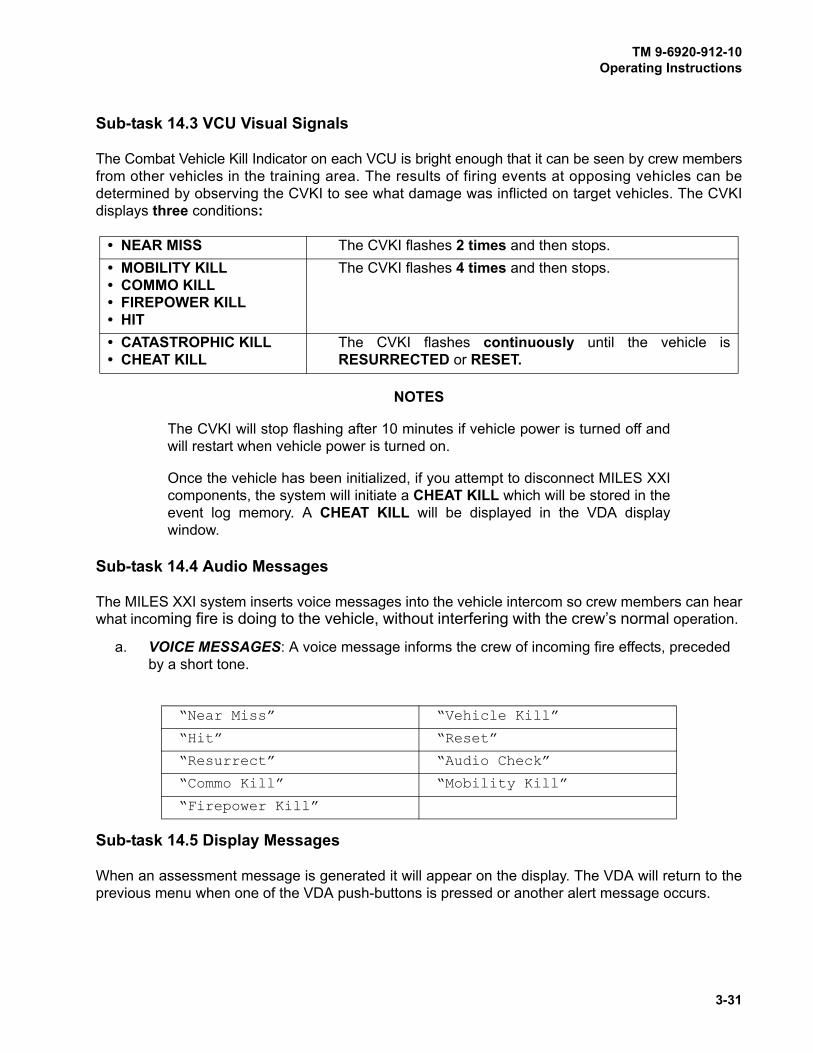
TM 9-6920-912-10Operating Instructions
3-31
Sub-task 14.3 VCU Visual Signals
The Combat Vehicle Kill Indicator on each VCU is bright enough that it can be seen by crew members
from other vehicles in the training area. The results of firing events at opposing vehicles can be
determined by observing the CVKI to see what damage was inflicted on target vehicles. The CVKI
displays three conditions:
NOTES
The CVKI will stop flashing after 10 minutes if vehicle power is turned off and
will restart when vehicle power is turned on.
Once the vehicle has been initialized, if you attempt to disconnect MILES XXI
components, the system will initiate a CHEAT KILL which will be stored in the
event log memory. A CHEAT KILL will be displayed in the VDA display
window.
Sub-task 14.4 Audio Messages
The MILES XXI system inserts voice messages into the vehicle intercom so crew members can hear
what incoming fire is doing to the vehicle, without interfering with the crew’s normal operation.
a. VOICE MESSAGES: A voice message informs the crew of incoming fire effects, preceded
by a short tone.
Sub-task 14.5 Display Messages
When an assessment message is generated it will appear on the display. The VDA will return to the
previous menu when one of the VDA push-buttons is pressed or another alert message occurs.
• NEAR MISS The CVKI flashes 2 times and then stops.
• MOBILITY KILL • COMMO KILL• FIREPOWER KILL• HIT
The CVKI flashes 4 times and then stops.
• CATASTROPHIC KILL• CHEAT KILL
The CVKI flashes continuously until the vehicle is
RESURRECTED or RESET.
“Near Miss” “Vehicle Kill”
“Hit” “Reset”
“Resurrect” “Audio Check”
“Commo Kill” “Mobility Kill”
“Firepower Kill”

TM 9-6920-912-10Operating Instructions
3-32
a. Use the UP/DOWN scroll push-button to display “PRESS SELECT FOR EVENT STATUS”, and press the “SELECT” push-button on the VDA. If you have events, the VDA
will display:
b. Scroll down to display the most recent event in the form of:
c. A casualty assessment event will be in the form of:
d. When the oldest event has been reached, the VDA will return to the most recent event.
T I M E - H HMM S S
Y Y Y Y I S X X X X
HHMMSS = Hour:Minutes:Seconds
YYYY = PID
XXXX = Status (ALIVE, DEAD, FPK,
MOBK, COMK)
# # - H HMM S S E E E E E
Y Y Y Y Y
## = EVENT NUMBER 1 - 99 (stores up to 500 events)
HHMMSS = HOUR:MIN:SEC
EEEEE = EVENT TYPE (See Table 3-3, (MILES XXI EVENT
TYPES)
YYYYY = EVENT INFO SUPPORTING DATA
# # H HMM S S E E E E Z
C C P I D - A # # # #
## = EVENT NUMBER 1 - 99 (stores up to 500 events)
HHMMSS = HOUR:MIN:SEC
EEEEZ = EVENT and HIT ZONE EVENT type (MISS, HIT, KILL, FPK,
MOBK and COMK) and HIT ZONE 1 - 8
CC = ATTACKING WEAPON (See Table 3-4 (MILES WEAPON CODES)
A = AMMO TYPE A - P
PID = ATTACKERS PID (####) 1-3330

TM 9-6920-912-10Operating Instructions
3-33
NOTES
The following event types may be viewed in the VDA.
* Denotes those associated with an instrumented range system.
Table 3-3 EVENT TYPES
Event Displayed Definition
*CHEM Indirect fire occurred.
*DECON Decon occurred.
*TRIGRD Trigger pulled.
ACQUIR An individual SAT has been learned.
BIT Displayed during a BIT event.
CHEAT Cheat event has occurred.
COMK Commo Kill occurred.
DEVICE Displayed when a component is missing.
EVTCLR Events cleared.
FAILUR Failure of component during BIT.
FIRED Weapon has been fired.
FPK Firepower Kill occurred.
GPSFIX VCU GPS is tracking.
HIT Hit occurred.
INITIALIZED System initialized, all detector belts configured and ready for use.
KILL Kill occurred.
LOWBAT VCU or SAT low battery.
MISS Near Miss occurred.
MOBK Mobility Kill occurred.
PLASUM Player summary for the AAR.
POWER Status od VCU battery.
PWR ON Power On (VCU).
RE-ACQ An individual SAT has been re-learned.
READY All expected SAT’s have been learned.
RESET Reset has been conducted.
RESUR Resurrect has been conducted.
SETPID Set player identification.
TIME Current time displayed.
VEH ON Vehicle On (vehicle power).
VEHOFF Vehicle Off (vehicle power).
WPNDRP Weapon learned has been dropped.

TM 9-6920-912-10Operating Instructions
3-34
Table 3-4 MILES WEAPON CODES
Code Weapon Simulation
00 UNIVERSAL KILL - Controller Device
01 MAVERICK
02 HELLFIRE
03 AT-3 SAGGER
04 MORTAR
05 MINE M15
06 WEAPON X
07 TOW
08 DRAGON
09 FIRE AND FORGET MISSILE
10 M21 ANTITANK MINE
11 CLAYMORE
12 105mm
13 152mm
14 ROCKET
15 AT4
16 120mm
17 90mm
18 ARTILLERY
19 GRENADE
20 ROCKET CLUSTER BOMB
21 30mm
22 25mm
23 20mm
24 HEAVY MACHINE GUN
25 CHAPPARRAL
26 STINGER
27 LIGHT MACHINE GUN
28 HEAVY MISS
29 LIGHT MISS
30 OPTICAL RESURRECT
31 HEAVY SPARE MISS
32 INDIRECT FIRE SIMULATOR
33 SA-14
34 RADAR
35 ADMIN
36 RESET

TM 9-6920-912-10Operating Instructions
3-35
Sub-task 15.1 Direct Fire Events
After the vehicle has been engaged by direct fire, one or more of the following assessment
messages will be displayed.
ACTION:
a. KILL -- When the vehicle has been killed, the following indications will occur:
NOTE
If the RIA is present the VDA will not beep, however, if the VDA beeps that
indicates the RIA is not being recognized by the system (conduct
troubleshooting).
TASK
15 Evaluate Direct Fire Events
VDA = Continuous tone
Audio Message = Tone\”VEHICLE KILL”
CVKI = Flashes Continuously.
VDA Displays:
# # H HMM S S E E E E Z
C C P I D - A # # # #
## = EVENT NUMBER 1 - 99 (stores up to 500 events)
HHMMSS = HOUR:MIN:SEC
EEEEZ = EVENT and HIT ZONE EVENT type KILL, and HIT ZONE 1 - 8
CC = ATTACKING WEAPON (See Table 3-4 (MILES WEAPON CODES)
A = AMMO TYPE A - P
PID = ATTACKERS PID (####) 1-3330
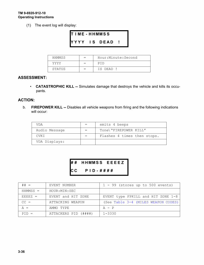
TM 9-6920-912-10Operating Instructions
3-36
(1) The event log will display:
ASSESSMENT:
• CATASTROPHIC KILL -- Simulates damage that destroys the vehicle and kills its occu-
pants.
ACTION:
b. FIREPOWER KILL -- Disables all vehicle weapons from firing and the following indications
will occur:
T I M E - H HMM S S
Y Y Y Y I S D E A D !
HHMMSS = Hour:Minute:Second
YYYY = PID
STATUS = IS DEAD !
VDA = emits 4 beeps
Audio Message = Tone\“FIREPOWER KILL”
CVKI = Flashes 4 times then stops.
VDA Displays:
# # H HMM S S E E E E Z
C C P I D - # # # #
## = EVENT NUMBER 1 - 99 (stores up to 500 events)
HHMMSS = HOUR:MIN:SEC
EEEEZ = EVENT and HIT ZONE EVENT type FPKILL and HIT ZONE 1-8
CC = ATTACKING WEAPON (See Table 3-4 (MILES WEAPON CODES)
A = AMMO TYPE A - P
PID = ATTACKERS PID (####) 1-3330

TM 9-6920-912-10Operating Instructions
3-37
(1) The event log will display:
ASSESSMENT:
• FIREPOWER KILL -- Disables all vehicle weapons from firing.
ACTION:
c. MOBILITY KILL -- Assesses vehicle damage that requires the vehicle to stop moving. In the
event of a Mobility Kill, the following indications will occur:
T I M E - H HMM S S
Y Y Y Y I S F P K I L L
HHMMSS = Hour:Minute:Second
YYYY = PID
STATUS = FIREPOWER KILL
VDA = emits 4 beeps
Audio Message = Tone\“MOBILITY KILL”
CVKI = Flashes 4 times then stops.
VDA Displays:
# # H HMM S S E E E E Z
C C P I D - A # # # #
## = EVENT NUMBER 1 - 99 (stores up to 500 events)
HHMMSS = HOUR:MIN:SEC
EEEEZ = EVENT and HIT ZONE EVENT type MOBKILL and HIT ZONE 1-8
CC = ATTACKING WEAPON (See Table 3-4 (MILES WEAPON CODES)
A = AMMO TYPE A - P
PID = ATTACKERS PID (####) 1-3330

TM 9-6920-912-10Operating Instructions
3-38
(1) The event log will display:
ASSESSMENT:
• MOBILITY KILL -- You must stop vehicle within 20 seconds. The crew may use the vehi-
cle weapons and radio. If you do not stop the vehicle within 20 seconds, the intercom will
beep, the vehicle will receive a Cheat Kill and the VDA will display “DEAD” until the vehi-
cle has been RESURRECTED or RESET.
ACTION:
d. COMMUNICATIONS KILL -- Causes vehicle damage and the crew must stop using the
radios except in an emergency:
T I M E - H HMM S S
Y Y Y Y I S MO B K
HHMMSS = Hour:Minute:Second
YYYY = PID
STATUS = MOBILITY KILL
VDA = emits 4 beeps
Audio Message = Tone\“COMMO KILL”
CVKI = Flashes 4 times then stops.
VDA Displays:
# # H HMM S S E E E E Z
C C P I D - A # # # #
## = EVENT NUMBER 1 - 99 (stores up to 500 events)
HHMMSS = HOUR:MIN:SEC
EEEEZ = EVENT and HIT ZONE EVENT type COMKILL and HIT ZONE 1 -
8
CC = ATTACKING WEAPON (See Table 3-4 (MILES WEAPON CODES)
A = AMMO TYPE A - P
PID = ATTACKERS PID (####) 1-3330

TM 9-6920-912-10Operating Instructions
3-39
(1) The event log will display:
ASSESSMENT:
• COMMUNICATIONS KILL -- Requires the crew to stop using vehicle radios except in an
emergency.
ACTION:
e. HIT -- When the vehicle has been HIT but sustains no damage, the following indications will
occur:
ASSESSMENT:
• HIT -- Vehicle was struck by incoming fire but no damage occurred.
ACTION:
T I M E - H HMM S S
Y Y Y Y I S C OMK
HHMMSS = Hour:Minute:Second
YYYY = PID
STATUS = COMMUNICATIONS KILL
VDA = emits 4 beeps
Audio Message = Tone\"HIT".
CVKI = Flashes 4 times then stops.
VDA Displays:
# # H HMM S S E E E E Z
C C P I D - A # # # #
## = EVENT NUMBER 1 - 99 (stores up to 500 events)
HHMMSS = HOUR:MIN:SEC
EEEEZ = EVENT and HIT ZONE EVENT type HIT and HIT ZONE 1 - 8
CC = ATTACKING WEAPON (See Table 3-4 (MILES WEAPON CODES)
A = AMMO TYPE A - P
PID = ATTACKERS PID (####) 1-3330

TM 9-6920-912-10Operating Instructions
3-40
f. NEAR MISS -- When a NEAR MISS occurs to the vehicle, the following indications will occur:
ASSESSMENT:
• NEAR MISS -- This indicates incoming fire hits close to the vehicle but does not hit the
vehicle itself or cause any damage.
Sub-task 15.2 Resurrect
• Bring players "Alive" -- DOES NOT restore ammunition loads.
a. To conduct a RESURRECT, fire the MILES XXI CD using the RESURRECT HOTKEY (F2) at
one of the detector belts.
• If the vehicle has been killed, a resurrect will cause the CVKI to stop flashing. You will hear
a voice message announcing “Resurrect” over the intercom.
b. The VDA will display:
VDA = emits 2 beeps
Audio Message = Tone\"Near MISS".
CVKI = Flashes 2 times then stops.
VDA Displays:
# # H HMM S S E E E E Z
C C P I D - A # # # #
## = EVENT NUMBER 1 - 99 (stores up to 500 events)
HHMMSS = HOUR:MIN:SEC
EEEEZ = EVENT and HIT ZONE EVENT type MISS and HIT ZONE 1 - 8
CC = ATTACKING WEAPON (See Table 3-4 (MILES WEAPON CODES)
A = AMMO TYPE A - P
PID = ATTACKERS PID (####) 1-3330
T I M E - H HMM S S
Y Y Y Y I S A L I V E !
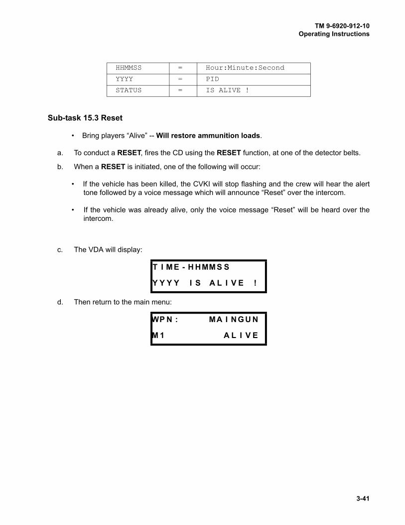
TM 9-6920-912-10Operating Instructions
3-41
Sub-task 15.3 Reset
• Bring players “Alive” -- Will restore ammunition loads.
a. To conduct a RESET, fires the CD using the RESET function, at one of the detector belts.
b. When a RESET is initiated, one of the following will occur:
• If the vehicle has been killed, the CVKI will stop flashing and the crew will hear the alert
tone followed by a voice message which will announce “Reset” over the intercom.
• If the vehicle was already alive, only the voice message “Reset” will be heard over the
intercom.
c. The VDA will display:
d. Then return to the main menu:
HHMMSS = Hour:Minute:Second
YYYY = PID
STATUS = IS ALIVE !
T I M E - H HMM S S
Y Y Y Y I S A L I V E !
WP N : MA I N G U N
M 1 A L I V E
TM 9-6920-912-10Operating Instructions
3-42
SECTION III LIVE FIRE OPERATION TASKS
MILES XXI can be used during Live Fire Training, either as an additional safety measure for Range
Control to Crew communications, or for modified “live fire” Targetry, i.e. firing Coax, M2, and M240 on
live-fire targets while firing Main Gun on MILES targets to conserve 120 mm ammunition.
For Live Fire operations, the following additional tasks should be performed.
If using MILES XXI while firing live 120mm rounds, perform the following:
a. Power the MILES XXI system OFF.
b. Disconnect and stow the Main Gun Laser Transmitter (MGLT).
c. Power the MILES XXI System ON, and RESET it using a Controller Device
(CD).
d. Use the procedure described in Section II, Task 3 - Vehicle Configuration, to
change the vehicle type to “M1.lf”. This “Live Fire” configuration permits the
MILES XXI to operate without the MGLT properly.
TASK
1 Configure Vehicle for Main Gun Live Fire

TM 9-6920-912-10Operating Instructions
3-43
SECTION IV POST OPERATION TASKS
a. To power down the vehicle and MILES XXI system, turn off VCU power, vehicle Master and
Turret power.
b. Clear all weapons and simulators of blank ammunition and cartridges.
Never pack detector belts when they are wet or damp.
Remove all MILES equipment prior to washing vehicles. High waterpressure can damage and or destroy the equipment.
c. Remove all MILES XXI equipment, in reverse order of installation.
d. Ensure equipment is dry and free of dirt and oil.
NOTE
Do not remove the fastener tape from vehicle.
a. Refer to Chapter 4, SECTION II (PREVENTIVE MAINTENANCE CHECKS AND SERVICES
(PMCS) and Perform After Operation Checks and Services.
b. Ensure all installation hardware (nuts, bolts, washers, etc.) are reattached to the appropriate
bracket and components.
c. Ensure all brackets and components are placed back in the transit case.
d. Return all equipment to the point of issue.
TASK
1 Power Down and Remove MILES XXI Equipment
CAUTION
TASK
2 Perform PMCS and Return MILES XXI Equipment

TM 9-6920-912-10
3-44
This page intentionally left blank.

TM 9-6920-912-10
4-1
CHAPTER 4MAINTENANCE INSTRUCTIONS
SECTION I GENERAL MAINTENANCE INFORMATION
4.1 GENERAL
The maintenance procedures for the MILES XXI equipment are divided into two sections. The first
section is Preventive Maintenance Checks and Services (PMCS). This section covers the Before,
During and After checks conducted by the crew to ensure the safe and proper operation of the
equipment. Most problems can be avoided by performing proper installation and PMCS of the
equipment.
The second section is Troubleshooting. Listed in this section are some of the common malfunctions
the crew might encounter while operating the equipment. The Troubleshooting table is divided into
three columns. The first column lists the System/Subsystem, the second lists a Malfunction and the
third lists the appropriate figure for the troubleshooting procedures. Follow the steps to isolate and
correct the malfunction. When you think you have solved the problem go back and recheck all steps.
Check to ensure the original malfunction is no longer there. The manual cannot list all possible
malfunctions, nor all the corrective actions. If a malfunction is not listed, or is not corrected by the
listed corrective action, report the malfunction IAW unit procedures.
SECTION II PREVENTIVE MAINTENANCE CHECKS AND SERVICES (PMCS)
4.2 GENERAL
Proper PMCS will ensure the MILES XXI equipment will be ready for operation and will perform
throughout the training mission. PMCS consist of performing a systematic inspection to discover
problems before they result in operational failure of the equipment. Component malfunctions
discovered during training or as a result of performing PMCS, will be reported using DA Form 2404.
a. Before operation, follow all WARNINGS and CAUTIONS.
b. Perform your “During” (D) PMCS periodically during the training exercise.
c. At the conclusion of training inspect equipment and perform “After” (A) PMCS.
d. If your equipment fails to operate, troubleshoot using proper test equipment and procedures.
4.3 EXPLANATION OF PMCS COLUMNS
4.3.1 Item To Be Inspected
Description of the equipment or portion of equipment to be checked or serviced.

TM 9-6920-912-10Maintenance Instructions
4-2
4.3.2 Interval
Each column is identified with a letter corresponding to the required interval: B - Before Operation, D- During Operation, A - After Operation, W - Weekly, M - Monthly. Each column will be marked by an
“x” to show when checks or services should be performed.
4.3.3 Procedures: Check for and Have Repaired
Describes the actions and procedures to accomplish checks and services, including information on
tools, materials to be used, gauge readings, etc.
4.3.4 Equipment Is Not Ready/Available If
Identifies conditions that make the equipment not ready/available for training. Identified equipment
shall not be used until corrective maintenance has been performed.
Table 4-1 PREVENTIVE MAINTENANCE CHECKS AND SERVICES (PMCS)
NOTE
Within designated interval, these checks are to be performed in the order
listed.
B - Before D - During A - After W - Weekly M - Monthly Operation Operation Operation Operation Operation
Item To Be InspectedInterval
Procedures: Check For And Have Repaired
Equipment Is Not Ready/Available If:
B D A W M
System Cables and
Connectors
x x x Inspect for worn or bare
wires.
Inspect connectors for
bent or damaged pins.
Bare wires are present.
Connectors or pins are
damaged.
VDA x x x Inspect for cracks in
display window.
Inspect for evidence of
status switch damage.
Inspect connectors for
bent or damaged pins.
Display window broken.
Status switch broken.
Connectors or pins are
damaged.
VCU x x x Inspect for cracks in CVKI
plastic lens.
Check for mounting
hardware.
Check for receptacle and
switch damage.
Inspect connector for bent
or damaged pins.
Inspect fuse holder for
damage and presence.
Inspect antennas for
damage and presence.
Cracks are evident. VCU
strobe light does not work.
Connections cannot be
made.
Connector or pins are
damaged.
Fuse is missing from fuse
holder or blown.

TM 9-6920-912-10Maintenance Instructions
4-3
Detector Belts x x x Wipe all detectors clean.
Inspect for damage that
would prevent normal
operation.
Inspect connectors for
bent or damaged pins.
Detectors or connectors
broken, bare wires
exposed.
If more than one detector
is bad.
Connectors or pins are
damaged.
RIA x x x Inspect RIA for deep dents
or evidence of crushing, or
missing hardware.
Inspect connectors for
broken or bent pins.
Holes in casing or other
damage that causes box
not to be water tight.
Any damaged, missing, or
broken pins.
Terminators x x x Inspect connectors for
bent or damaged pins.
Connectors or pins are
damaged.
FCI x x x Inspect RIA for deep dents
or evidence of crushing, or
missing hardware.
Inspect connectors for
broken or bent pins.
Holes in casing or other
damage that causes box
not to be water tight.
Any damaged, missing, or
broken pins.
MGLT x x x Inspect connectors for
bent or damaged pins.
Inspect LASER XMTR for
cracks or missing
hardware.
Clean laser output lens.
Connectors or pins are
damaged.
LASER XMTR assembly is
cracked or hardware is
missing to prevent normal
operation.
Mounting Brackets x x Inspect brackets for burrs
or obstructions that would
prevent secure mounting
to the vehicle.
Inspect to ensure all
mounting hardware is
available and that the
fastener tape is present
(when applicable).
If the mounting bracket
cannot be mounted to the
vehicle, or the component
cannot be mounted to the
bracket.
SAT
(M2 and M240)
x x x Clean laser output lens.
Inspect mounting bracket
for damage
Cracked laser output lens.
Missing or damaged
mounting hardware.
Table 4-1 PREVENTIVE MAINTENANCE CHECKS AND SERVICES (PMCS) (Continued)
NOTE
Within designated interval, these checks are to be performed in the order
listed.
B - Before D - During A - After W - Weekly M - Monthly Operation Operation Operation Operation Operation
Item To Be InspectedInterval
Procedures: Check For And Have Repaired
Equipment Is Not Ready/Available If:
B D A W M

TM 9-6920-912-10Maintenance Instructions
4-4
SECTION III TROUBLESHOOTING
4.4 GENERAL
NOTE
Do not connect or disconnect cables when VCU power is ON.
Table 4-2 (TROUBLESHOOTING) lists malfunctions that you may encounter during operation or
maintenance of the MILES XXI system. Perform the tests or inspections listed.
If a malfunction is not listed or is not corrected by the recommended troubleshooting procedure,
report the malfunction IAW unit procedures.
For all failures:
a. Ensure all equipment is properly installed.
b. Check all cable connections and ensure cables are properly installed and connections are
tight.
c. Ensure vehicle master power, turret power, and utility power is “ON”.
d. Verify the proper “Vehicle Type” is selected on the VDA.
e. If you receive BIT failure messages, go immediately to the section in the troubleshooting
table that covers that piece of equipment and perform the troubleshooting procedures.
f. If any piece of equipment fails, report the malfunction IAW unit procedures.
4.4.1 System Configuration Troubleshooting
Once the equipment is powered on and the vehicle configuration is correct and the detector belts
have been initialized, do the following procedures. The procedures listed will allow the operator to
determine if the VCU has recognized all connected components within the vehicle system.
a. Scroll through the VDA main menus and press “SELECT” to select “SELECT AUX MENU”
from the VDA display.
b. Scroll through the “SELECT AUX MENU” sub-menus until you find the “SELECT SYSTEM CONFIG” display.

TM 9-6920-912-10Maintenance Instructions
4-5
c. Press “SELECT” to “SELECT SYSTEM CONFIG” sub-menu and the display should
display the following text:
Figure 4-1 “SELECT SYSTEM CONFIG” Display
• 1-4 - denotes the total number of belts expected for the configured vehicle,
• M - denotes MGLT
• L - denotes VDA
• R - denotes RIA
• C - denotes CVKI DRIVER
• F - denotes FCI
• S - denotes M240 SAT
• 2 - denotes M2 SAT
d. All items highlighted with an “+” denote the VCU has recognized those components
connected within the system configuration. A “-” indicates that the component has not been
recognized in the configuration of the vehicle kit. Additionally, the VDA should display any
component that has not been recognized during BIT.
NOTE
A “D” may be shown as the last character in the SYSTEM CONFIG display if
the MILES XXI has been configured for use in Instrumented Mode. If an
Instrumentation set is not connected for vehicle tracking, the “D” may be
ignored.
e. Any BIT failure, or lack of vehicle power, generates 5 beeps from the VDA or vehicle
intercom system. The VDA generates the following display when vehicle power is off or not
connected:
1 2 3 4 M L R C F S 2
+ + + + + + + + + + +
N O V E H I C L E P OWE R
T O M I L E S

TM 9-6920-912-10Maintenance Instructions
4-6
Table 4-2 TROUBLESHOOTING
System/Subsystem Malfunction Figure
SYSTEM POWERED
BIT Failure Figure 4-2 (General MILES XXI
Troubleshooting)
VDA No Display Figure 4-3 (VDA Has No Display)
Up and Down Buttons Not
Operational
Figure 4-4 (VDA Push-buttons Not
Operational)
No Backlight Figure 4-5 (VDA Has No Backlight)
Buzzer Does Not Sound Figure 4-6 (VDA Buzzer Does Not
Sound)
VCU No Power Figure 4-7 (VCU Will Not Power
Up)
No Strobe Light Figure 4-8 (VCU Strobe CVKI Will
Not Flash)
Cannot Communicate With The
CD
Figure 4-9 (No RF Communication
Between VCU and CD)
GENERAL FAULTS Locks Up Figure 4-10 (General Faults,
System Not Responding)
INCOMING FIRE DETECTION
Detector Belts Does Not Detect MILES Codes Figure 4-11 (Detector Belt Not
Functioning)
HUTT HUTT Failure Or Not Functioning Figure 4-12 (HUTT Not
Functioning Properly)
COMMUNICATIONS
RIA No Audio Cues Figure 4-13 (Audio Cues Not Being
Heard)
OUTGOING FIRE
Coax Does Not Fire Figure 4-14 (COAX Does Not Fire)
120mm Main Gun For All MGSS Failures Refer To
The Operators Manual
Figure 4-15 (Main Gun Will Not
Fire)
SAT Will Not Acquire/Learn Figure 4-16 (SAT Will Not Acquire/
Learn)
VERIFICATION CHECKS
All Systems and Subsystems Operational Verification Checks
After All Faults Have Been
Corrected
Figure 4-17 (Operational
Verification of the MILES XXI
System)

TM 9-6920-912-10Maintenance Instructions
4-7
Figure 4-2 General MILES XXI Troubleshooting
GENERAL MILES XXI TROUBLESHOOTING
GO TO TABLE 4-2TROUBLESHOOTINGAND IDENTIFY SUSPECTSYSTEM/SUBSYSTEM
NOYES
YES
YES
NO
NO
FOR ALL FAILURES
INSURE ALL EQUIPMENT IS PROPERLY INSTALLED
CHECK ALL CABLE CONNECTIONS
VERIFY MILES IS RECEIVING POWER AND VEHICLE POWER IS ON
VERIFY PROPER VEHICLE TYPE IS SELECTED IN VDA
ARE THERE ANY BIT FAILURE MESSAGES
IS FAILED HARDWARE DIFCUE
IS IT INSTALLED
NOT REQUIRED FOR SYSTEM TO FUNCTION,
REFER TO DIFCUE OPERATORS MANUAL
DISREGARD BIT FAILURE MESSAGE
REVIEW VDA EVENT STATUS TO DETERMINEFAILED ITEM
VERIFY ALL COMPONENTS ARE PRESENT (+) IN VDA SYSTEM CONFIG DISPLAY

TM 9-6920-912-10Maintenance Instructions
4-8
Figure 4-3 VDA Has No Display
VDA HAS NO DISPLAY
NOYES
VDA HAS NO DISPLAY
TURN VCU OFF THEN BACK ON
IS CVKI LIGHT FLASHING
TROUBLESHOOT VCU PER FIGURE 4-8
IS PROBLEM SOLVED
YES
VERIFY SYSTEM IS OPERATIONALPER FIGURE 4-17
REPLACE SYSTEM BUSCABLE 2031039-16
IS PROBLEM SOLVED
YES
NO
REPORT EQUIPMENT FAILUREPER UNIT SOP
REPLACE VDA
YES NO
IS PROBLEM SOLVED
DISCONNECT BUS CABLE
TURN ON VCU
TURN ON VCU
TURN OFF VCU
NO
AND DETECTOR BELTS).FROM VCU-J2 (TO MGLT
TURN ON VCU
IS PROBLEM SOLVED
YES NO
PROBLEM LIES WITHDETECTOR BELTS ORASSOCIATED CABLES.TROUBLESHOOTPER FIGURE 4-11

TM 9-6920-912-10Maintenance Instructions
4-9
Figure 4-4 VDA Push-buttons Not Operational
NOYES
VDA BUTTONS NOT OPERATIONAL
DEPRESS EACH BUTTON ON THE VDA
DID ANY BUTTON FAIL
REPLACE VDA
YES NO
VDA PUSH-BUTTONS NOT OPERATIONAL
TURN VCU OFF THEN BACK ON
RESET SYSTEM WITH CD
VERIFY SYSTEM IS OPERATIONALPER FIGURE 4-17
IS PROBLEM SOLVED
VERIFY SYSTEM IS OPERATIONALPER FIGURE 4-17
REPLACE SYSTEM BUSCABLE 2031039-16
IS PROBLEM SOLVED
YES NO
TROUBLESHOOT VCU PERFIGURE 4-7
TURN OFF VCU
TURN ON VCU
TURN OFF VCU
TURN ON VCU

TM 9-6920-912-10Maintenance Instructions
4-10
Figure 4-5 VDA Has No Backlight
VDA HAS NO BACKLIGHT
NOYES
VDA BACKLIGHT IS NOT VISIBLE
IS BACKLIGHT VISIBLE IN
VERIFY BACKLIGHT IS SELECTED ON THE VDA
REPORT ON 2404, CONTINUE MISSION
SET BACKLIGHT TO:DIM,NOR
AND HIGH
ALL SETTINGS
YES NO
REPORT ON 2404, CONTINUE MISSION
VERIFY SYSTEM IS OPERATIONALPER FIGURE 4-17
IS PROBLEM SOLVED
YES NO
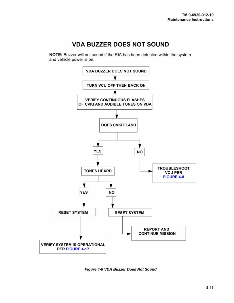
TM 9-6920-912-10Maintenance Instructions
4-11
Figure 4-6 VDA Buzzer Does Not Sound
TURN VCU OFF THEN BACK ON
VERIFY CONTINUOUS FLASHESOF CVKI AND AUDIBLE TONES ON VDA
DOES CVKI FLASH
NOYES
TONES HEARD
NOYES
VERIFY SYSTEM IS OPERATIONALPER FIGURE 4-17
TROUBLESHOOTVCU PER
FIGURE 4-8
REPORT AND CONTINUE MISSION
VDA BUZZER DOES NOT SOUND
VDA BUZZER DOES NOT SOUND
RESET SYSTEM RESET SYSTEM
NOTE: Buzzer will not sound if the RIA has been detected within the systemand vehicle power is on.

TM 9-6920-912-10Maintenance Instructions
4-12
Figure 4-7 VCU Will Not Power Up
NOYES
CHECK VCU POWER
IS VCU BATTERY INSTALLED
INSTALL AND CONNECTBATTERY
IS SYSTEM
YES NO
VERIFY POWER IS ON
YES NO
PROPERLY AND CONNECTED
CONNECTED TO VEHICLEPOWER
CONNECT SYSTEM TOVEHICLE POWER
RECYCLE VCU POWER
VERIFY SYSTEM ISOPERATIONAL
PER FIGURE 4-17
REPLACE VCU
IS PROBLEM SOLVED
YES NOREPLACE SYS
IS PROBLEM SOLVED
YES NOREPORT EQUIPMENT FAILURE
PER UNIT SOP
CABLE 2031480-3
IS PROBLEM SOLVED
TURN OFF VCUTURN ON VCU
IS VEHICLE PROVIDINGPOWER (CHECK UTILITYPOWER)
YES NO
TURN UTILITY POWER ON
IS PROBLEM SOLVED
NO YES
VCU WILL NOT POWER UP
NOTE: Wait 5 secondsbefore recycling VCUpower.
AND CHECK FUSE

TM 9-6920-912-10Maintenance Instructions
4-13
Figure 4-8 VCU Strobe CVKI Will Not Flash
NOYES
CHECK ALL VCU CONNECTIONS
ARE ALL CABLES CONNECTED
CONNECT CABLESVERIFY VCU POWERSWITCH IS ON
IS THE VDA DISPLAY ON
NOYES
IS PROBLEM SOLVED
NOYES
REPORT EQUIPMENT FAILUREPER UNIT SOP
VERIFY SYSTEM ISOPERATIONAL
PER FIGURE 4-17
REPLACE VCU
TURN OFF VCU
TURN ON VCU
VCU STROBE CVKI WILL NOT FLASH
CONFIRM VDA ISOPERATIONAL
TROUBLESHOOT VCUPER FIGURE 4-7

TM 9-6920-912-10Maintenance Instructions
4-14
Figure 4-9 No RF Communication Between VCU and CD
NO RF COMMUNICATION BETWEEN VCU AND CD
NO
IS VCU POWERED UP
IS CD OPERATIONAL
TROUBLESHOOT CD PER
NOYES
DO THE CD AND VCU COMMUNICATE
CD OPERATORS MANUALSHOOT CD AT ADIFFERENT BELT
NOYES
TROUBLESHOOT FIRST BELT PER
FIGURE 4-11
USE A KNOWN GOOD CDAND SHOOT BELT
DO THE CD AND VCU COMMUNICATE
NOYES
VERIFY SYSTEM ISOPERATIONAL
PER FIGURE 4-17
TROUBLESHOOTVCU
PER FIGURE 4-7
POWER UP VCU
YES
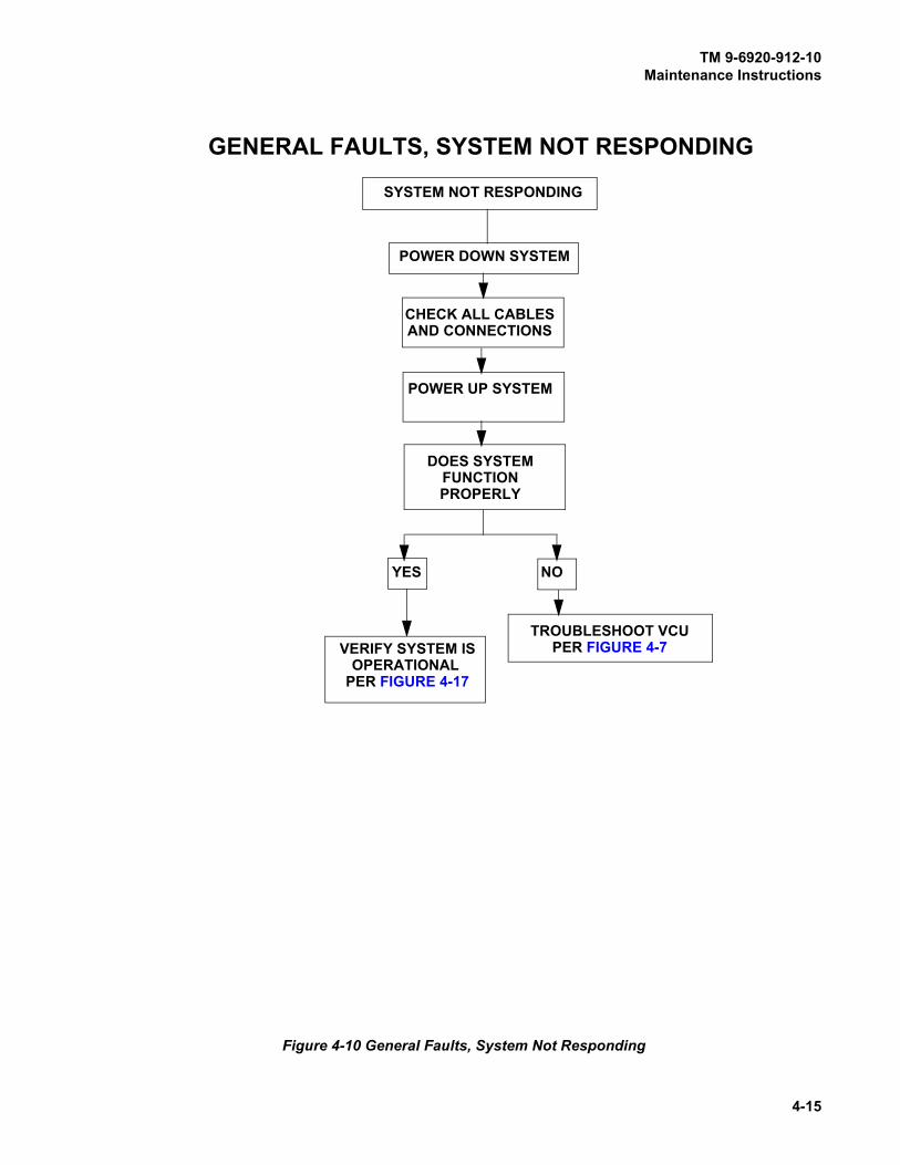
TM 9-6920-912-10Maintenance Instructions
4-15
Figure 4-10 General Faults, System Not Responding
GENERAL FAULTS, SYSTEM NOT RESPONDING
POWER DOWN SYSTEM
SYSTEM NOT RESPONDING
TROUBLESHOOT VCU
NOYES
PER FIGURE 4-7
CHECK ALL CABLESAND CONNECTIONS
POWER UP SYSTEM
DOES SYSTEMFUNCTIONPROPERLY
VERIFY SYSTEM ISOPERATIONAL
PER FIGURE 4-17

TM 9-6920-912-10Maintenance Instructions
4-16
Figure 4-11 Detector Belt Not Functioning
DETECTOR BELT NOT FUNCTIONING
IS DETECTOR BELT CONNECTED PROPERLY
DETECTOR BELT NOT FUNCTIONING
CONNECT AND INITIALIZE BELT
NOYES
VERIFY SYSTEM ISOPERATIONAL
PER FIGURE 4-17
YES NOIS PROBLEM CORRECTED
PER CHAPTER 4, PARAGRAPH 4.4.1IS DETECTORBELT PRESENT
REPLACE DETECTORBELTS
IN VEH SYS CONFIG
REINITIALIZE BELTYESNO
REFER TO 4.4.1 SYSTEM
IS PROBLEM CORRECTED
NOYES
VERIFY SYSTEM ISOPERATIONAL
PER FIGURE 4-17
IS PROBLEM CORRECTED
NOYES
VERIFY SYSTEM ISOPERATIONAL
PER FIGURE 4-17
IS PROBLEM CORRECTED
NOYES
TROUBLESHOOTVCU PER
FIGURE 4-7
TURN OFF VCU
TURN ON VCU
CONFIGURATIONTROUBLESHOOTING
INSPECT BELT AND SYSTEM BUS CABLE TOPREVIOUS BELT IN BUS CHAIN FOR DAMAGE
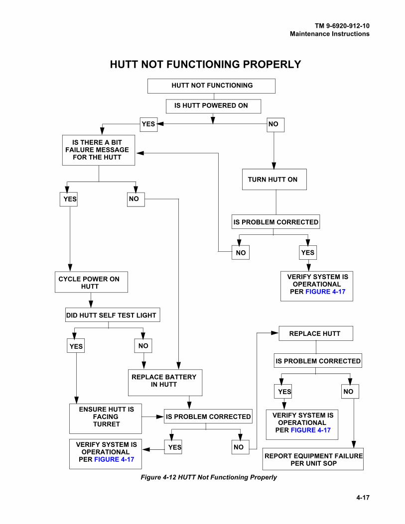
TM 9-6920-912-10Maintenance Instructions
4-17
Figure 4-12 HUTT Not Functioning Properly
HUTT NOT FUNCTIONING PROPERLY
IS HUTT POWERED ON
HUTT NOT FUNCTIONING
TURN HUTT ON
NOYES
VERIFY SYSTEM ISOPERATIONAL
PER FIGURE 4-17
YES NO
IS PROBLEM CORRECTED
IS THERE A BIT
YESNO
CYCLE POWER ON HUTT
DID HUTT SELF TEST LIGHT
NOYES
ENSURE HUTT ISFACING TURRET
VERIFY SYSTEM ISOPERATIONAL
PER FIGURE 4-17
REPLACE BATTERYIN HUTT
IS PROBLEM CORRECTED
NOYES
REPLACE HUTT
IS PROBLEM CORRECTED
NOYES
REPORT EQUIPMENT FAILUREPER UNIT SOP
VERIFY SYSTEM ISOPERATIONAL
PER FIGURE 4-17
FAILURE MESSAGEFOR THE HUTT

TM 9-6920-912-10Maintenance Instructions
4-18
Figure 4-13 Audio Cues Not Being Heard
AUDIO CUES NOT BEING HEARD
INSURE RIA IS CONNECTED
IS PROBLEM CORRECTED
NOYES
VERIFYVERIFY SYSTEM IS
OPERATIONAL PER FIGURE 4-17
IS THE RIA IN THE
NOYES
INSURE VCU POWER SWITCH IS ON
INSURE VEHICLE POWER IS ON
INSURE VEHICLE INTERCOM IS ON AND OPERATIONAL
INSURE CVC IS CONNECTED AND OPERATIONAL
RIA AUDIO CABLE (2030485-2) ISCONNECTED TO THE MASTER
CONTROL CONSOLE, AUDIO INPUT JACKS
VEH SYSTEM CONFIG
RESET SYSTEM WITH CD
IS PROBLEM CORRECTED
YESNO
VERIFY SYSTEM ISOPERATIONAL
PER FIGURE 4-17
REPLACE RIA
IS PROBLEM CORRECTED
NOYES
TROUBLESHOOTVCU PER
FIGURE 4-7
TURN OFF VCU
TURN ON VCU
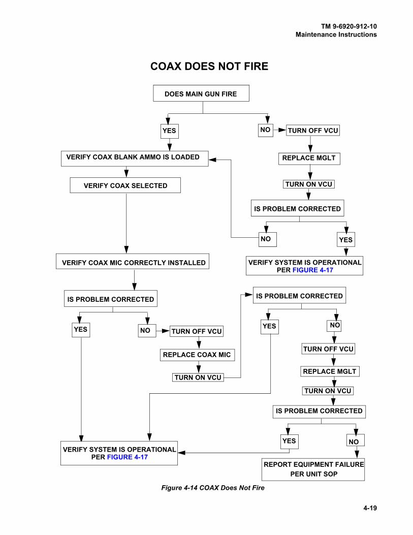
TM 9-6920-912-10Maintenance Instructions
4-19
Figure 4-14 COAX Does Not Fire
COAX DOES NOT FIRE
IS PROBLEM CORRECTED
DOES MAIN GUN FIRE
NOYES
REPLACE MGLT
VERIFY COAX SELECTED
VERIFY COAX MIC CORRECTLY INSTALLED
NOYES
REPLACE COAX MIC
IS PROBLEM CORRECTED
NOYES
VERIFY SYSTEM IS OPERATIONALPER FIGURE 4-17
REPLACE MGLT
IS PROBLEM CORRECTED
NOYES
REPORT EQUIPMENT FAILUREPER UNIT SOP
IS PROBLEM CORRECTED
YESNO
VERIFY SYSTEM IS OPERATIONALPER FIGURE 4-17
VERIFY COAX BLANK AMMO IS LOADED
TURN OFF VCU
TURN ON VCU
TURN OFF VCU
TURN ON VCU
TURN OFF VCU
TURN ON VCU

TM 9-6920-912-10Maintenance Instructions
4-20
Figure 4-15 Main Gun Will Not Fire
IS PROBLEM CORRECTED
DOES COAX FIRE
NOYES
REPLACE MGLTDOES MAIN GUN AMMO COUNT IN
YESNO
REPLACE FCI
YESNO
RE-ALIGN
REPORT EQUIPMENT FAILUREPER UNIT SOP
MAIN GUN DOES NOT FIRE
PER FIGURE 4-17VERIFY SYSTEM IS OPERATIONAL
IS PROBLEM CORRECTED
YESNO
REPLACE FCI CABLE 2031588-1
IS PROBLEM CORRECTED
YES
NO
REPLACE MGLT CABLE 2031496-1
IS PROBLEM CORRECTED
YES
NO
IS PROBLEM CORRECTED
YESNO
TURN OFF VCU
TURN ON VCUVDA DECREASE WHEN FIRED
TURN OFF VCU
TURN ON VCU
TURN OFF VCU
TURN ON VCU
TURN OFF VCU
TURN ON VCU
VERIFY TURRET POWERAND UTILITY POWER IS ON

TM 9-6920-912-10Maintenance Instructions
4-21
Figure 4-16 SAT Will Not Acquire/Learn
SAT WILL NOT ACQUIRE/LEARNVERIFY VDA BUZZER
NOYES
PRESS SAT LEARN BUTTON
NO YES
ON VDA, GO TO “SELECT LEARN WEAPON
PRESS ‘SELECT’ TO INITIATE LEARN PROCESS
REPLACE SAT
IS OPERATIONAL PERFIGURE 4-6
DOES VDA GIVE 1 LONG BEEP?
DISPLAY UNDER THE ADMIN FUNCTIONS SUBMENU
IMMEDIATELY AFTER HEARINGLONG BEEP FROM VDA
REPLACE VCU
DOES VDA GIVE 3 LONG BEEP?
DOES VDA GIVE 3 SHORT BEEPS WITHIN APPROXIMATELY 20 SECONDS
NOYES
DOES VDA GIVE 2 LONG BEEP?
NO
REPLACE VCU
CHECK VDA AND VERIFY
REPEAT, AND IFSAME RESULTS,REPLACE SAT
YES
VERIFY SYSTEM ISOPERATIONAL
FIGURE 4-17
THAT SAT IS ACQUIRED

TM 9-6920-912-10Maintenance Instructions
4-22
Figure 4-17 Operational Verification of the MILES XXI System
INSURE SYSTEM IS POWERED UP
INSURE AUDIO MESSAGE IS HEARD THRU THE INTERCOM FOR EACH NEAR MISS
INSURE SYSTEM HAS BEEN RESET BY CD
USING THE CD SHOOT A HEAVY NEAR MISS CODE (28) AT EACH BELT
INSURE CVKI FLASHES 2 TIMES WHEN CD SHOOTS EACH BELT
VERIFY THAT EACH EVENT IS LOGGED IN THE VDA EVENT LOG
IF ALL STEPS ARE NOT SUCCESSFUL RETURN TO TABLE 4-2 TROUBLESHOOTING
REALIGN SYSTEM IF MGLT WAS REMOVED OR REPLACED
OPERATIONAL VERIFICATION OF THE MILES XXI SYSTEM
VERIFY THAT MGLT FIRES LASER FOR ALL WEAPONS (USEDRYFIRE CONFIGURATION FOR COAX
VERIFY THAT M2 AND M240 SATS ARE “LEARNED”, AND FIRELASER CODES WHEN TRIGGERED

TM 9-6920-912-10
A-1
APPENDIX AREFERENCES
A.1 SCOPE
Appendix A lists forms, field manuals, technical manuals, and miscellaneous publications that are
referenced in this manual and or related to the MILES XXI equipment.
A.2 FORMS
SF 368 Quality Deficiency Report
DA Form 2028-2 Recommended Changes to DA Publications
DA Form 2404 Equipment Inspection and Maintenance Work Sheet
DA Form 2062 Hand Receipt
A.3 FIELD MANUALS
FM 4-25.11 Field Manual: First Aid for Soldiers
A.4 TECHNICAL MANUALS
TM 9-6920-210-10 Operator’s Manual: MILES XXI, CVS kit for M113 Armored Personnel
Carriers
TM 9-6920-211-10 Operator’s Manual: MILES XXI, CVS kit for M2/M3A2 and M2/M3A3
Bradley Fighting Vehicles
TM 9-6920-913-10 After Action Review
TM 9-6920-3659-10 Controller Device (CD) Operator’s Manual
TM 9-6920-893-10 Operator’s Manual: MILES 2000 TESS For Direct/Indirect Fire Cue
TM 9-1005-215-10 Operator's Manual: M2 Machine Gun
TM 9-2350-264-10 Operator’s Manual: M1A1 Main Battle Tank
TM 9-2350-288-10 Operator’s Manual: M1A2 Main Battle Tank
TM 9-2350-388-10 Operator’s Manual: M1A2 SEP Main Battle Tank
TM 38-750 The Army Maintenance Management System -TAMMS
TM 9-1005-314-12&P Operator’s and Organizational Maintenance Manual: Blank Firing
Adapter (BFA) M19 for Cal 50 M2 Machine Gun
SMM 9-6920-908-24&P System Maintenance Manual, for MILES XXI CVS
A.5 MISCELLANEOUS PUBLICATIONS
AR 310-2 Identification and Distribution of DA Publications
DA PAM 738-750 The Army Maintenance Management System (TAMMS)

TM 9-6920-912-10References
A-2
SB 11-6 Dry Battery Supply Data
CTA 50-970 Expendable/Durable Items (Except: Medical, Class V, Repair Parts
and Heraldic Items)
TB 43-1034 Batteries, Disposition and Disposal
TM 9-6920-912-10
B-1
APPENDIX BEXPENDABLE/DURABLE SUPPLIES AND MATERIALS LIST
SECTION I INTRODUCTION
B.1 SCOPE
This appendix lists the expendable supplies and materials needed to operate and maintain the
MILES XXI equipment. This listing is for informational purposes only.
B.2 EXPLANATION OF COLUMNS
a. Column (1) - Item Number; this number is assigned to the entry in the listing and is
referenced in the narrative instructions to identify the material.
b. Column (2) - Level; this column identifies the lowest level of maintenance that requires the
listed item (e.g., C - Operator/Crew).
c. Column (3) - National Stock Number; this is the National Stock Number assigned to the item.
d. Column (4) - Description Federal Supply Classification for Manufacturers (FSCM) & Part
Number. Indicates the federal item name and, if required, a description to identify the item.
The last line for each item indicates the FSCM in parentheses followed by the part number.
e. Column (5) - Unit of Measure; indicates the measure used in performing the actual
maintenance function. This measure is expressed by a two character alphabetical
abbreviation (e.g., ea., in., pr.). If the unit of measure differs from the unit of issue, requisition
the lowest unit of issue that will satisfy your requirements.
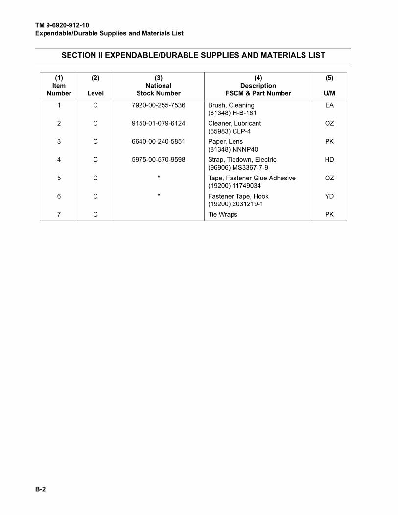
TM 9-6920-912-10Expendable/Durable Supplies and Materials List
B-2
SECTION II EXPENDABLE/DURABLE SUPPLIES AND MATERIALS LIST
(1)Item
Number
(2)
Level
(3)National
Stock Number
(4)Description
FSCM & Part Number
(5)
U/M
1 C 7920-00-255-7536 Brush, Cleaning
(81348) H-B-181
EA
2 C 9150-01-079-6124 Cleaner, Lubricant
(65983) CLP-4
OZ
3 C 6640-00-240-5851 Paper, Lens
(81348) NNNP40
PK
4 C 5975-00-570-9598 Strap, Tiedown, Electric
(96906) MS3367-7-9
HD
5 C * Tape, Fastener Glue Adhesive
(19200) 11749034
OZ
6 C * Fastener Tape, Hook
(19200) 2031219-1
YD
7 C Tie Wraps PK

TM 9-6920-912-10
C-1
APPENDIX CEQUIPMENT DESCRIPTION
SECTION I DESCRIPTION
C.1 M1A1/M1A2/M1A2 SEP COMMON COMPONENTS
NOTE
The following provides a brief description of the Abrams series tank MILES XXI
components. Numbers to the right of the component name correspond to the
item number of the component graphic at the end of this section.
Vehicle Control Unit (VCU) (1)
NOTE
The VCU battery requires an initial charge upon receipt of the equipment.
Additionally, the VCU battery is shipped disconnected from the VCU.
The VCU contains the master computer for the MILES XXI system. The VCU interprets the effects of
direct fire simulation on the vehicle. Audio and visual responses to the effect of direct fire are
generated by the VCU and made available to the crew through the vehicle intercom system, the
Vehicle Display Assembly, and the Combat Vehicle Kill Indicator (CVKI).
The VCU contains a strobe light (CVKI) that provides the visual responses in the form of flashes to
the effects of incoming direct fire as follows: two flashes for a NEAR MISS and four flashes for a
FIREPOWER KILL, MOBILITY KILL, COMMUNICATIONS KILL, and a HIT and continuous flashes
for a CATASTROPHIC KILL. The audio messages through the intercom system report a: VEHICLEKILL, MOBILITY KILL, COMMUNICATIONS KILL, HIT, or NEAR MISS.
Figure C-1 M1A1 Abrams Series Vehicle
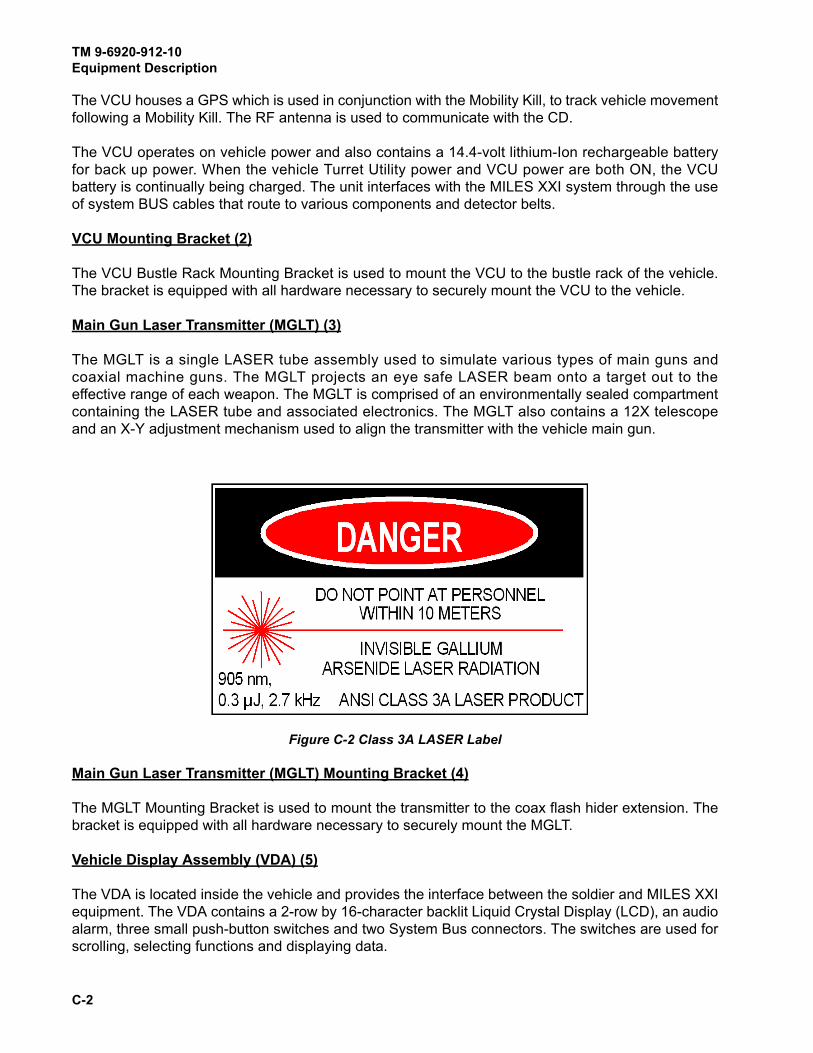
TM 9-6920-912-10Equipment Description
C-2
The VCU houses a GPS which is used in conjunction with the Mobility Kill, to track vehicle movement
following a Mobility Kill. The RF antenna is used to communicate with the CD.
The VCU operates on vehicle power and also contains a 14.4-volt lithium-Ion rechargeable battery
for back up power. When the vehicle Turret Utility power and VCU power are both ON, the VCU
battery is continually being charged. The unit interfaces with the MILES XXI system through the use
of system BUS cables that route to various components and detector belts.
VCU Mounting Bracket (2)
The VCU Bustle Rack Mounting Bracket is used to mount the VCU to the bustle rack of the vehicle.
The bracket is equipped with all hardware necessary to securely mount the VCU to the vehicle.
Main Gun Laser Transmitter (MGLT) (3)
The MGLT is a single LASER tube assembly used to simulate various types of main guns and
coaxial machine guns. The MGLT projects an eye safe LASER beam onto a target out to the
effective range of each weapon. The MGLT is comprised of an environmentally sealed compartment
containing the LASER tube and associated electronics. The MGLT also contains a 12X telescope
and an X-Y adjustment mechanism used to align the transmitter with the vehicle main gun.
Figure C-2 Class 3A LASER Label
Main Gun Laser Transmitter (MGLT) Mounting Bracket (4)
The MGLT Mounting Bracket is used to mount the transmitter to the coax flash hider extension. The
bracket is equipped with all hardware necessary to securely mount the MGLT.
Vehicle Display Assembly (VDA) (5)
The VDA is located inside the vehicle and provides the interface between the soldier and MILES XXI
equipment. The VDA contains a 2-row by 16-character backlit Liquid Crystal Display (LCD), an audio
alarm, three small push-button switches and two System Bus connectors. The switches are used for
scrolling, selecting functions and displaying data.

TM 9-6920-912-10Equipment Description
C-3
The VDA is also used by the crew to view current vehicle configuration, vehicle status, previous
events, Built In Test (BIT) status and software version. Up to 500 recorded events may be stored in
the VCU and can be viewed on the VDA by using the push-button switches. The VDA provides an
audio alarm when no intercom is used.
Vehicle Detection System (VDS) (6)
The VDS is comprised of four independent detector belt segments. Each detector belt is equipped
with IR photo detectors mounted on webbed fabric with Velcro backing for easy attachment to the
vehicle. The VDS consists of one detector belt segment for each of the four belt locations (front, rear,
left side and right side). Their are eight primary hit zones on the vehicle which are displayed on the
VDA during incoming firing events, refer to Chapter 3, Figure 3-7 (Vehicle Hit Zones). The detector
belts are connected together and cabled into the system BUS via the system BUS cabling.
Radio Interface Assembly (RIA) (7)
The RIA allows the crew to hear current vehicle status. The RIA, through the interface cabling,
provides the necessary electrical interface to inject voice cues into the vehicle intercom system.
Fire Control Interface (FCI) (8)
The FCI interfaces with the fire control system. The FCI uses an electrically isolated interface circuit
to receive weapon system signals from the vehicles fire control system.
Power Cable Assembly (9)
The Vehicle Power/Interface Cable connects the VCU to the vehicle utility power (UJ1) on the Turret
Networks Box (TNB) in the M1A1. The Vehicle Power/Interface Cable connects the VCU to the
Commander’s Remote Switching Module (RSM) 5 or UJ1 in the M1A2/M1A2 SEP.
RIA Cable Assembly (10)
The RIA cable connects the vehicle intercom system Master Control Station (MCS) with the RIA
assembly.
System BUS Cables (11)
The System BUS Cables carry data and power between the VCU and other components of the
MILES XXI system. The cables are 4 wire conductors with identical connectors at both ends. Only
the length of the cables vary. The System BUS Cable interconnects all modular assemblies in a
daisy chain fashion.
Terminators (12)
Terminators are used to provide network impedance matching for the System BUS. Two terminators
are used in the MILES XXI kit.
Hull-to-Turret Transmitter (HUTT) (13)
The HUTT determines which way the turret is pointing by transmitting a continuous signal to the
VDS. The VCU uses turret orientation to determine the zone from which fire was received.

TM 9-6920-912-10Equipment Description
C-4
M240 Coax Microphone Trigger Assembly (14)
A specially designed microphone that attaches to the coax BFA. The microphone transforms the
percussion of blank ammunition being fired by the coax into an electrical signal that is sent to the
MGLT. The MGLT then emits a coded LASER beam onto a target out to the effective range of the
coax machine gun.
Transit Case (15)
The Transit Case provides a means of transporting and storing the MILES XXI system. It is
constructed of durable, high-density polyethylene thermoplastic material. The case has firm foam
inserts with cutout areas designed to accommodate the various types of MILES XXI components,
providing maximum protection to the equipment.
M2 Machine Gun (MG) Small Arms Transmitter (SAT) (16)
The SAT mounts to the commanders machine gun to simulate firing. The SAT is activated by firing
blank ammunition, or by the use of a Dry Fire Trigger cable. The M2 MG SAT projects an eye safe
LASER beam onto a target out to the effective range of the weapon. See Figure C-2, Class 3A
LASER Label.
M240 Machine Gun (MG) Small Arms Transmitter (SAT) (17)
The SAT mounts to the loaders machine gun to simulate firing. The SAT is activated by firing blank
ammunition, or by use of a Dry Fire Trigger cable. The M240 SAT projects an eye safe LASER beam
onto a target out to the effective range of the weapon. See Figure C-2, Class 3A LASER Label.
C.1.1 M1A1 Specific Components
FCI Cable Assembly (18)
The M1A1 FCI cable assembly connects the FCI to the fire control system through TJ1 and TJ2 on
the TNB.
C.1.2 M1A2/M1A2 SEP Specific Components
FCI Cable Assembly (19)
The M1A2/M1A2 SEP FCI cable assembly connects the FCI to the fire control system through TJ2
on the Fire Control Electronics Unit (FCEU).
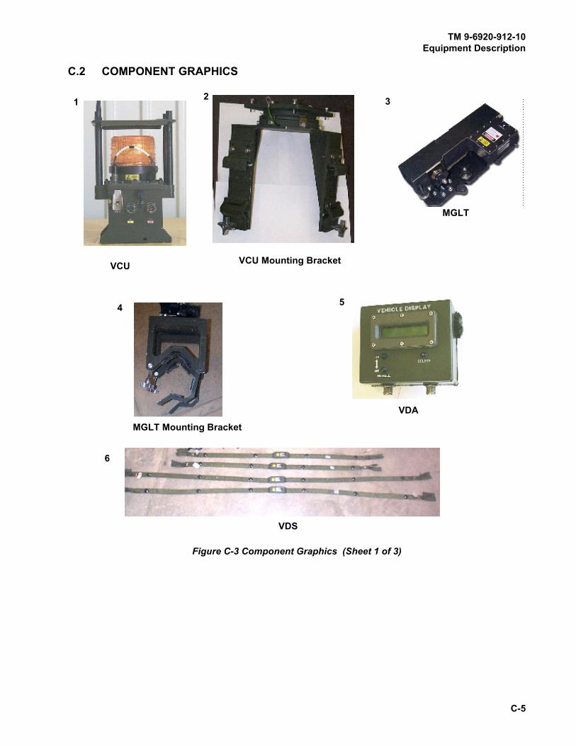
TM 9-6920-912-10Equipment Description
C-5
C.2 COMPONENT GRAPHICS
Figure C-3 Component Graphics (Sheet 1 of 3)
1 3
VDS
6
5
VCU Mounting Bracket
4
2
VDA
VCU
MGLT Mounting Bracket
MGLT

TM 9-6920-912-10Equipment Description
C-6
Figure C-3 Component Graphics (Sheet 2 of 3)
7
RIA
8
FCI
9
Power Cable Assembly
11
System BUS Cables
10 12
Terminator (2)
RIA Cable Assembly
13
HUTT
14
COAX MIC Trigger Assembly

TM 9-6920-912-10Equipment Description
C-7
Figure C-3 Component Graphics (Sheet 3 of 3)
15
Transit Case
16
M2 SAT
19
M1A2/M1A2 SEP FCI Cable Assembly
M1A1 FCI Cable Assembly
1817
M240 SAT

TM 9-6920-912-10Equipment Description
C-8
SECTION II EQUIPMENT INSPECTION
C.3 M1A1/M1A2/M1A2 SEP COMMON COMPONENTS
.
a. Wipe all detectors (1) clean and inspect for any visible damage.
b. Inspect the cloth harness (2) for fraying or other damage.
c. Look for cuts, tears or other obvious damage. Inspect the electronics module (3) for cracks,
dents or other obvious damage.
d. Check the connector (4) for bent pins or other damage.
e. Inspect the back of the belts to make sure the “fuzzy” fastener tape is in good condition and
there is enough, to install the belts.
TASK
1 Inspect Detector Belts
Figure C-4 Detector Belt Inspection
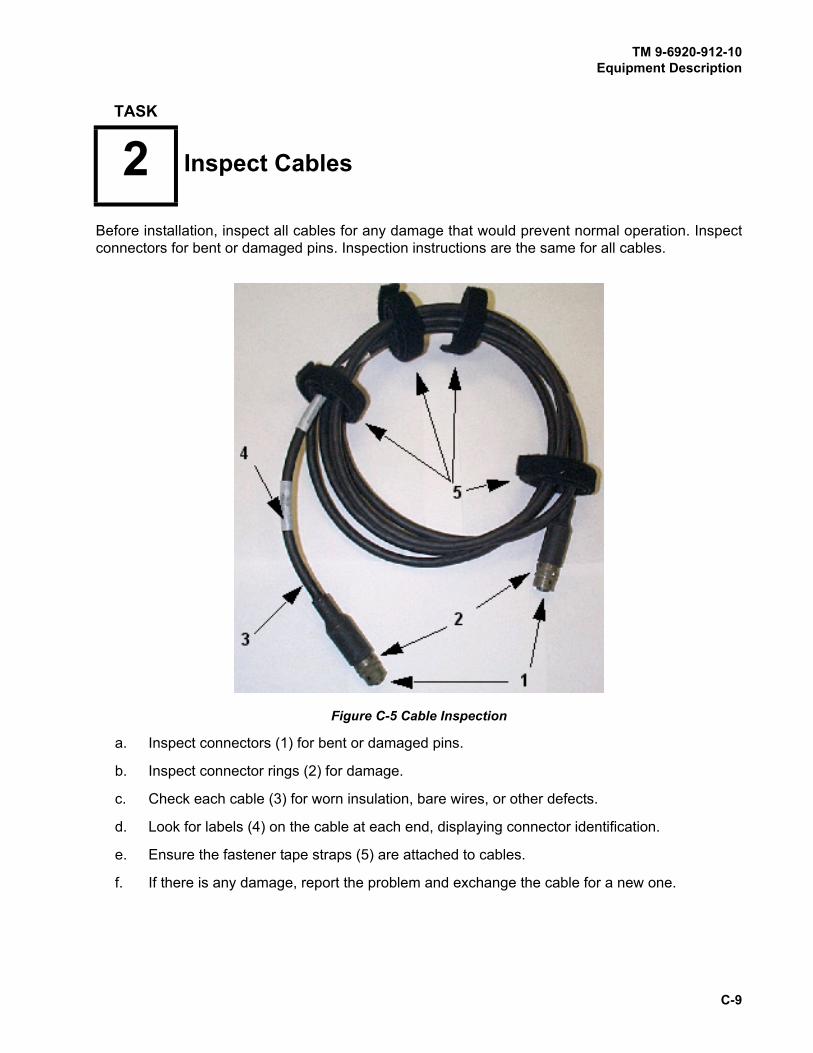
TM 9-6920-912-10Equipment Description
C-9
Before installation, inspect all cables for any damage that would prevent normal operation. Inspect
connectors for bent or damaged pins. Inspection instructions are the same for all cables.
a. Inspect connectors (1) for bent or damaged pins.
b. Inspect connector rings (2) for damage.
c. Check each cable (3) for worn insulation, bare wires, or other defects.
d. Look for labels (4) on the cable at each end, displaying connector identification.
e. Ensure the fastener tape straps (5) are attached to cables.
f. If there is any damage, report the problem and exchange the cable for a new one.
TASK
2 Inspect Cables
Figure C-5 Cable Inspection

TM 9-6920-912-10Equipment Description
C-10
a. Inspect the VCU for any damage that could prevent normal operation. If there is any damage
that could keep the assembly from working, exchange it for a new one.
b. Inspect On/Off toggle switch (1) to ensure it is not bent to prevent the VCU from being turned
On and Off.
c. Inspect connectors (2) for bent or damaged pins.
d. Inspect the battery compartment (3) for corrosion or any damage. If there is any damage,
report the problem and exchange the VCU for a new one. The battery requires an initial
charge upon receipt of the equipment.
NOTE
When inserting the battery, insert the widest end of the battery first, with the
cable connector on the same side as the cable to allow for ease of installation
and removal.
e. Inspect fuse holder (4) for damaged or missing fuse.
f. Inspect for missing or damaged antennas (5).
g. Inspect the CVKI (6) for cracks or other damage.
h. Report any damage and exchange the VCU for a new one.
TASK
3 Inspect Vehicle Control Unit (VCU)
Figure C-6 VCU Inspection
2 3
1
6
5
4
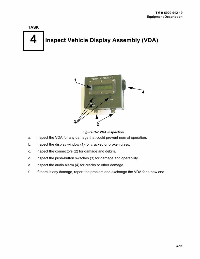
TM 9-6920-912-10Equipment Description
C-11
a. Inspect the VDA for any damage that could prevent normal operation.
b. Inspect the display window (1) for cracked or broken glass.
c. Inspect the connectors (2) for damage and debris.
d. Inspect the push-button switches (3) for damage and operability.
e. Inspect the audio alarm (4) for cracks or other damage.
f. If there is any damage, report the problem and exchange the VDA for a new one.
TASK
4 Inspect Vehicle Display Assembly (VDA)
Figure C-7 VDA Inspection
1
32
4
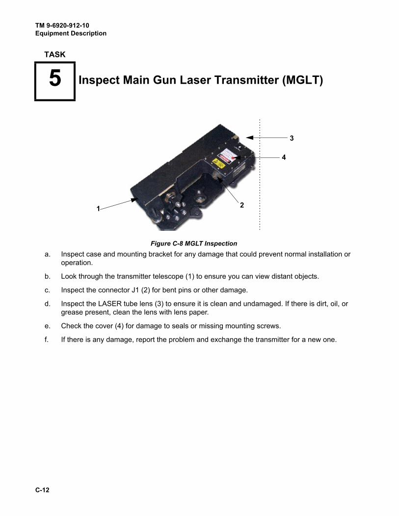
TM 9-6920-912-10Equipment Description
C-12
a. Inspect case and mounting bracket for any damage that could prevent normal installation or
operation.
b. Look through the transmitter telescope (1) to ensure you can view distant objects.
c. Inspect the connector J1 (2) for bent pins or other damage.
d. Inspect the LASER tube lens (3) to ensure it is clean and undamaged. If there is dirt, oil, or
grease present, clean the lens with lens paper.
e. Check the cover (4) for damage to seals or missing mounting screws.
f. If there is any damage, report the problem and exchange the transmitter for a new one.
TASK
5 Inspect Main Gun Laser Transmitter (MGLT)
Figure C-8 MGLT Inspection
3
4
21

TM 9-6920-912-10Equipment Description
C-13
a. Inspect the FCI Assembly for any damage that could prevent normal operation.
b. Inspect the connectors (1) for damage and debris.
c. If there is any damage, report the problem and exchange the FCI Assembly for a new one.
a. Inspect the Terminators for any damage that could prevent normal operation.
b. Inspect the connector (1) for bent or damaged pins.
c. If there is any damage, report the problem and exchange the Terminator for a new one.
TASK
6 Inspect Fire Control Interface (FCI) Assembly
Figure C-9 FCI Inspection
TASK
7 Inspect Terminator
Figure C-10 Terminator Inspection
(hidden)
1
1

TM 9-6920-912-10Equipment Description
C-14
a. Check the case (1) for any damage that would prevent installation or operation.
b. Make sure the fastener tape on the bottom of the HUTT is in good condition.
c. Ensure the IR window plastic (2), is not cracked or broken.
d. Ensure the lanyard (3) is present and attached securely to the case.
e. Ensure the ON/OFF switch (4) is operable.
f. Ensure the battery indicator light (5) is not cracked or broken.
g. Loosen the thumb screw (6) in the battery compartment door (7) and inspect the battery
compartment to ensure it is clean, dry and the battery contacts are not corroded.
Excessive force can damage the battery compartment. Do not force the
battery compartment door closed.
h. Insert a 9-volt battery (8) into the compartment, close the door (7), and tighten the screw (6).
The battery will fit either way, polarity is not important.
TASK
8 Inspect Hull To Turret Transmitter (HUTT)
Figure C-11 HUTT Inspection
CAUTION

TM 9-6920-912-10Equipment Description
C-15
i. Turn the ON/OFF switch (4) to the ON position. After approximately 1 second, the red
battery indicator light should light for 1 to 3 seconds. If the light does not come on, replace
the battery with a new one and perform the test again.
j. After the battery indicator light does come on (battery test is good), turn the ON/OFF switch
to the OFF position.
k. If there is any damage report the problem and exchange the HUTT for a new one.
a. Inspect MGLT mounting plate (1) for damage that could prevent secure mounting of the
MGLT.
b. Inspect pads (2) (8 ea.) for damage.
c. Inspect tightening knobs (3) for functionality.
TASK
9 Inspect MGLT Mounting Bracket Assembly
Figure C-12 Main Gun Mount Assembly Inspection
1
2 (x8)
3

TM 9-6920-912-10Equipment Description
C-16
d. Report any damage that would prevent secure mounting of the MGLT to the vehicle and
exchange the MGLT Mounting Bracket for a new one.
a. Inspect cable (1) for bare or frayed wires.
b. Inspect clamp (2) for damage.
c. Inspect microphone (3) for damage that could prevent it from securely attaching to the
clamp.
TASK
10 Inspect Coax Microphone Trigger Assembly
Figure C-13 Coax Microphone Trigger Assembly Inspection
3
2 1
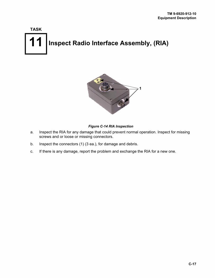
TM 9-6920-912-10Equipment Description
C-17
a. Inspect the RIA for any damage that could prevent normal operation. Inspect for missing
screws and or loose or missing connectors.
b. Inspect the connectors (1) (3 ea.), for damage and debris.
c. If there is any damage, report the problem and exchange the RIA for a new one.
TASK
11 Inspect Radio Interface Assembly, (RIA)
Figure C-14 RIA Inspection
1

TM 9-6920-912-10Equipment Description
C-18
a. Inspect the VCU Mounting Bracket for damage that would prevent secure mounting.
b. Ensure all hardware is available and undamaged.
c. If there is any damage exchange the mounting bracket for a new one.
TASK
12 Inspect VCU Mounting Bracket Assembly
Figure C-15 VCU Mounting Bracket Assembly Inspection

TM 9-6920-912-10Equipment Description
C-19
NOTE
All transit cases are similar in appearance however, the size may vary
depending on the amount of equipment contained inside.
a. Inspect for presence of carrying handles and latches. Inspect interior for presence and
condition of packing foam.
b. Inspect the MILES XXI Transit Case for any damage that would prevent proper closing or
indicate equipment damage.
c. If there is any damage to the Transit Case report the problem.
TASK
13 Inspect MILES XXI Transit Case
Figure C-16 MILES XXI Transit Case Inspection

TM 9-6920-912-10Equipment Description
C-20
Figure C-17 M2 SAT
a. Inspect the SAT for any damage that could prevent normal operation.
b. Ensure the transmitter lens (1) is clean and free from any debris that may reduce LASER
effectiveness.
c. Inspect Dry Fire connector (2) to ensure it is not cracked or clogged with debris.
d. Inspect the microphone port (3) for cracks or any damage that may prevent proper
functioning.
e. Inspect the lock nut (4) for presence and or damage that may prevent secure mounting of
the SAT mounting bracket to the machine gun barrel support.
f. Inspect the strap bolt (5) for damage that may prevent secure mounting of the SAT mounting
bracket to the machine gun barrel support.
g. Inspect alignment device holder (6) for damage that would prevent accommodating the
alignment device.
h. Inspect the SAT “POWER ON/LEARN” push-button (7) for presence and ensure the push-
button releases when pushed.
TASK
14 Inspect M2 Machine Gun Small Arms Transmitter (SAT)
1
2
3
4
5
6
7
(hidden)

TM 9-6920-912-10
C-21
This page intentionally left blank.
a. Inspect the M240 SAT for any damage that could prevent normal operation.
b. Ensure the transmitter lens (1) is clean and free from any debris that may reduce LASER
effectiveness.
c. Inspect microphone (2) for cracks, debris, and damage.
d. Inspect the mounting clamp (3) for cracks or other damage that may prevent secure
mounting of the transmitter to the gun barrel.
e. Inspect the SAT “POWER ON/LEARN” push-button (4) for presence and ensure the push-
button releases when pressed.
f. If there is any damage, report the problem and exchange the SAT for a new one.
TASK
15 Inspect M240 Small Arms Transmitter (SAT)
Figure C-18 M240 SAT Inspection
3
1
2
4

TM 9-6920-912-10
C-22
This page intentionally left blank.

TM 9-6920-912-10
D-1
APPENDIX DACRONYMS
Table D-1 ACRONYM LIST
ACRONYM DEFINITION
AAR After Action Review
AMMO Ammunition
ASSY Assembly
BFA Blank Fire Adapter
BII Basic Issue Items
BIT Built-In Test
BLUFOR Blue Forces (Friendly Forces)
BUS Background Utility System
CD Controller Device
CLP Cleaner, Lubricant, and Preservative
CLS Contractor Logistics Support
COAX Coaxial Machine Gun
COMK Communications Kill
COMMO Communications
CONFIG Configure
CPC Corrosion Prevention and Control
CVC Combat Vehicle Crewman
CVKI Combat Vehicle Kill Indicator
CVS Combat Vehicle System
DA Department of the Army
DIFCUE Direct, Indirect Fire Cue
DRMO Defense Reclamation Management Office
DRV’s Driver’s
DSP Display
ea./EA Each
FCI Fire Control Interface
FM Field Manual
FPK Fire Power Kill
FSCM Federal Stock/Supply Classification/Code for Manufacturers
GFE Government Furnished Equipment
HD Hundred
HE High Explosive

TM 9-6920-912-10Acronyms
D-2
IAW In Accordance With
IN or in Inch
INT Intercom
IR Infrared
IWS Individual Weapon System
J Jack
KM Kilometer
LASER Light Amplification by Stimulated Emission of Radiation
LAN Local Area Network
LCD Liquid Crystal Display
MAG Magnification
MALF Malfunction
MAX Maximum
MCS Master Control Station
MG Machine Gun
MGLT Main Gun LASER Transmitter
MGSS Main Gun Signature Simulator
MILES Multiple Integrated LASER Engagement System
mm Milli Meter
MOBK Mobility Kill
MOD Module
NOR Normal
NSN National Stock Number
OC Observer Controller
OPFOR Opposing Forces
OZ Ounce
PCU Power Control Unit
PEOSTRI Program Executive Office, for Simulation, Training and Instrumentation
PID Player Identification. Also known as “Player ID”
PK Probability of Kill or Package
PMCS Preventive Maintenance Checks and Services
PN or P/N Part Number
PWR Power
RIA Radio Interface Assembly
REM Remaining
RNDS Rounds
RSM Remote Switching Module
Table D-1 ACRONYM LIST (Continued)
ACRONYM DEFINITION
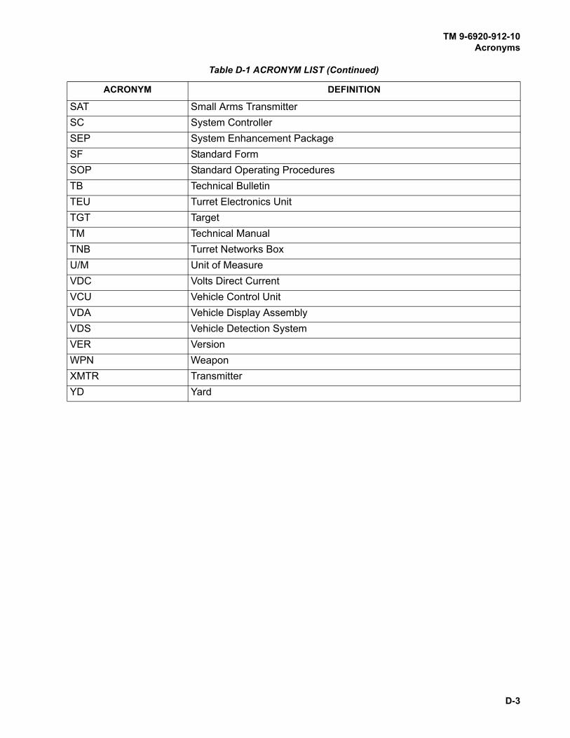
TM 9-6920-912-10Acronyms
D-3
SAT Small Arms Transmitter
SC System Controller
SEP System Enhancement Package
SF Standard Form
SOP Standard Operating Procedures
TB Technical Bulletin
TEU Turret Electronics Unit
TGT Target
TM Technical Manual
TNB Turret Networks Box
U/M Unit of Measure
VDC Volts Direct Current
VCU Vehicle Control Unit
VDA Vehicle Display Assembly
VDS Vehicle Detection System
VER Version
WPN Weapon
XMTR Transmitter
YD Yard
Table D-1 ACRONYM LIST (Continued)
ACRONYM DEFINITION

TM 9-6920-912-10
D-4
This page intentionally left blank.

TM 9-6920-912-10
E-1
APPENDIX EGLOSSARY
Table E-1 GLOSSARY DEFINITIONS
TERM EXPLANATION
Controller An umpire or referee in a MILES training exercise. Also referred to
as an “Observer/Controller” (OC).
Controller Device Device used to test MILES XXI detector systems, disqualify soldiers
or vehicles from the exercise, and RESURRECT/RESET soldiers
and vehicles. There are many functions of the CD not covered in this
manual.
Combat Vehicle Kill Indicator A MILES XXI Device that flashes when a vehicle is hit by incoming
fire. This signals other players in the exercise that the vehicle has
incurred damage.
Detector Belt A canvas belt containing detectors that senses the coded LASER
beams fired at it. Also known as VDS.
Domain A group of networked devices that share a common communications
address.
Dry Fire A setting that allows the MILES XXI system to fire LASER beams
without firing blank ammunition.
Fastener Tape Type of tape used to hold detector belts and other MILES equipment
in place.
HIT An event that simulates a direct hit upon the vehicle that causes
some damage but does not result in a KILL. There are four types of
HIT -- one causes no damage, each of the other “Kills” a certain
vehicle function. HIT -- NO DAMAGE alerts the crew that the vehicle
is under fire and should take evasive action.
KILL An event that simulates a direct hit upon the vehicle that causes the
vehicle to be totally disabled.
MOBILITY KILL simulates a track or engine hit, but allows the
vehicle to communicate and fire weapons.
FIREPOWER KILL simulates a hit to the vehicle’s weapon systems,
but allows the vehicle to move and to communicate.
COMMO KILL simulates an antenna hit, the crew must stop vehicle
movement.
Laser Beam A narrow beam of infrared light fired from transmitters mounted on
various weapons to simulate weapon fire.
Laser Detector MILES device that detects incoming LASER beams.
Laser Transmitter MILES device that transmits LASER beams.
MILES Code A number used by MILES to identify each type of simulated weapon.

TM 9-6920-912-10Glossary
E-2
NEAR MISS An event that is "close" enough to be detected by a MILES system,
but not close enough to cause a HIT or KILL.
Player Identification A letter followed by a 4-digit code used by the MILES XXI system, to
identify individual soldiers or vehicles during an exercise.
Reset Makes a MILES XXI equipped vehicle “Alive” after a Kill and
restores FULL ammunition basic loads to the VDA.
Resurrect To restore a MILES XXI equipped vehicle or individual to operable
condition following a KILL but does not restore ammunition basic
loads.
Simulator Training device that takes the place of real equipment and imitates
the equipment in training exercises.
Transmitter Simulates firing capability of a variety of main guns, machine guns,
and missiles that are programmed into the MILES XXI VCU.
Zone The LASER detectors on the outside of the turret are divided into
ZONE 1-8, which correspond to different sides of the vehicle. MILES
XXI uses this information (Probability of Kill), in assessing the
severity of damage when hit by incoming fire. If the VCU cannot
determine the zone accurately, the VCU and VDA displays will show
ZONE 0. The Zone (s) engaged will be displayed on the VDA.
Table E-1 GLOSSARY DEFINITIONS (Continued)
TERM EXPLANATION
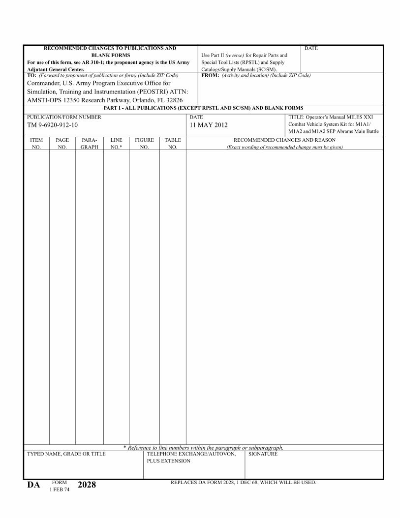
RECOMMENDED CHANGES TO PUBLICATIONS AND BLANK FORMS
For use of this form, see AR 310-1; the proponent agency is the US Army Adjutant General Center.
Use Part II (reverse) for Repair Parts and
Special Tool Lists (RPSTL) and Supply
Catalogs/Supply Manuals (SC/SM).
DATE
TO: (Forward to proponent of publication or form) (Include ZIP Code)Commander, U.S. Army Program Executive Office for
Simulation, Training and Instrumentation (PEOSTRI) ATTN:
AMSTI-OPS 12350 Research Parkway, Orlando, FL 32826
FROM: (Activity and location) (Include ZIP Code)
PART I - ALL PUBLICATIONS (EXCEPT RPSTL AND SC/SM) AND BLANK FORMS
PUBLICATION/FORM NUMBER
TM 9-6920-912-10
DATE
�� 0$< 2012
TITLE: Operator’s Manual MILES XXI
Combat Vehicle System Kit for M1A1/
M1A2 and M1A2 SEP Abrams Main Battle
ITEM
NO.
PAGE
NO.
PARA-
GRAPH
LINE
NO.*
FIGURE
NO.
TABLE
NO.
RECOMMENDED CHANGES AND REASON
(Exact wording of recommended change must be given)
* Reference to line numbers within the paragraph or subparagraph.TYPED NAME, GRADE OR TITLE TELEPHONE EXCHANGE/AUTOVON,
PLUS EXTENSION
SIGNATURE
DA FORM
1 FEB 742028 REPLACES DA FORM 2028, 1 DEC 68, WHICH WILL BE USED.
TO: (Forward to proponent of publication or form) (Include ZIP Code)Commander, U.S. Army Program Executive Office for
Simulation, Training and Instrumentation (PEOSTRI) ATTN:
AMSTI-OPS 12350 Research Parkway, Orlando, FL 32826
FROM: (Activity and location) (Include ZIP Code) DATE
PART II- REPAIR PARTS AND SPECIAL TOOL LISTS AND SUPPLY CATALOGS/SUPPLY MANUALS
PUBLICATION/FORM NUMBER
TM 9-6920-912-10
DATE
�� 0$Y 2012
TITLE: Operator’s Manual MILES XXI Combat
Vehicle System Kit for M1A1/M1A2 and M1A2 SEP
Abrams Main Battle Tanks
PAGE
NO.
COLM
NO.
LINE
NO.
FEDERAL STOCK
NUMBER
REFERENCE
NO.
FIGURE
NO.
ITEM
NO.
TOTAL NO.
OF MAJOR
ITEMS
SUPPROTED
RECOMMENDED ACTION
PART III - REMARKS (Any general remarks or recommendations, or suggestions for improvement of publications and blank forms. Additional blank sheets may be used if more space is needed.)
TYPED NAME, GRADE OR TITLE TELEPHONE EXCHANGE/AUTOVON, PLUS
EXTENSION
SIGNATURE
U.S. GOVERNMENT PRINTING OFFICE 1981 341-646/8606


Lockheed Martin Global Traning and LogisticsOrlando, Florida
GTL TP&T: MILESXXICVSM1 ������12