TM 55-1925-207-10-1 TECHNICAL MANUAL OPERATOR’ S MANUAL...
14
TM 55-1925-207-10-1 TECHNICAL MANUAL OPERATOR’S MANUAL FOR INLAND AND COASTAL LARGE TUG (LT) NSN 1925-01-247-7110 DISTRIBUTION STATEMENT A: Approved for Public Release; distribution is unlimited. HEADQUARTERS, DEPARTMENT OF THE ARMY 16 AUGUST 1991
Transcript of TM 55-1925-207-10-1 TECHNICAL MANUAL OPERATOR’ S MANUAL...

TM 55-1925-207-10-1
TECHNICAL MANUAL
OPERATOR’S MANUALFOR
INLANDAND COASTAL
LARGE TUG (LT)NSN 1925-01-247-7110
DISTRIBUTION STATEMENT A: Approved for Public Release; distribution is unlimited.
HEADQUARTERS, DEPARTMENT OF THE ARMY
16 AUGUST 1991

TM 55-1925-207-10
Change 2 i
TECHNICAL MANUAL HEADQUARTERS DEPARTMENT OF THE ARMY NO. 55-1925-207-10 WASHINGTON, D.C., 16 August 1991
OPERATOR’S MANUAL for
INLAND AND COASTAL LARGE TUG (LT)
NSN 1925-01-247-7110
REPORTING ERRORS AND RECOMMENDING IMPROVEMENTS You can help improve this publication. If you find any mistakes or if you know of a way to improve these procedures, please let us know. Submit your DA Form 2028 (Recommended Changes to Publications and Blank Forms), through the Internet, on the Army Electronic Product Support (AEPS) website. The Internet address is http://aeps.ria.army.mil. If you need a password, scroll down and click on “ACCESS REQUEST FORM.” The DA Form 2028 is located in the ONLINE FORMS PROCESSING section of the AEPS. Fill out the form and click on SUBMIT. Using this form on the AEPS will enable us to respond quicker to your comments and better manage the DA Form 2028 program. You may also mail, fax or e-mail your letter, or DA Form 2028 direct to: Technical Publication Information Office, TACOM-RI 1 Rock Island Arsenal, Rock Island, IL 61299-7630. The e-mail address is [email protected]. The fax number is DSN 793-0726 or Commercial (309) 782-0726.
DISTRIBUTION STATEMENT A: Approved for public release; distribution is unlimited.
TABLE OF CONTENTS
PAGE CHAPTER 1 INTRODUCTION..................................................................................................................................1-1 Section I General Information..................................................................................................................1-1 Section II Equipment Description .............................................................................................................1-5 Section III Technical Principles of Operation...........................................................................................1-97 CHAPTER 2 OPERATING INSTRUCTIONS ............................................................................................................2-1 Section I Description and Use of Operator’s Controls and Indicators......................................................2-1 Section II Preventive Maintenance Checks and Services (PMCS).......................................................2-312
Section III Operation Under Usual Conditions.......................................................................................2-397 Section IV Operation Under Unusual Conditions...................................................................................2-727

TM 55-1925-207-10
ii Change 1
TABLE OF CONTENTS - Continued CHAPTER 3 MAINTENANCE INSTRUCTIONS............................................................................................3-1
Section I Lubrication Instructions .............................................................................................................3-1
Section II Troubleshooting Procedures...................................................................................................3-38 Section III Maintenance Procedures ........................................................................................................3-38
APPENDIX A REFERENCES ........................................................................................................................ A-1
APPENDIX B COMPONENTS OF END ITEM AND BASIC ISSUE ITEMS LISTS ........................................ B-1
APPENDIX C ADDITIONAL AUTHORIZATION LIST..................................................................................... C-1
APPENDIX D EXPENDABLE/DURABLE SUPPLIES AND MATERIALS LIST .............................................. D-1
APPENDIX E STOWAGE AND SIGN GUIDE FOR COMPONENTS OF END ITEM, BASIC ISSUE ITEMS, AND APPLICABLE ADDITIONAL AUTHORIZATION LIST ITEMS............................................................................................................................. E-1
APPENDIX F ON-VEHICLE EQUIPMENT LOADING PLAN, INLAND AND CANAL LARGE TUG ............... F-1
APPENDIX G SOUNDING TABLES...............................................................................................................G-1
ALPHABETICAL INDEX .................................................................................................... Index-1

TM 55-1925-207-10
Change 2 1-1
CHAPTER 1
INTRODUCTION
PAGE
SECTION I GENERAL INFORMATION .............................................................................................................................1-1 SECTION II EQUIPMENT DESCRIPTION..........................................................................................................................1-5 SECTION III TECHNICAL PRINCIPLES OF OPERATION..................................................................................................1-97
SECTION I. GENERAL INFORMATION
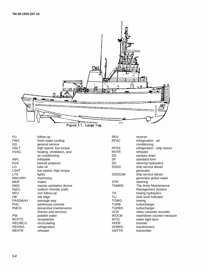
1-1. Scope. This is an operator's manual for the Large Tug (LT) (Figure 1-1). The LT performs coastal and ocean towing, docking, and undocking operations with large ocean vessels. These vessels include the SL-7 (FSS) LASH and SEABEE vessels. The LT also handles barges in the open ocean. The LT can provide fire fighting, salvage, and rescue help to other ships and shore installations on a limited basis. The vessel operates in inland waterways, coastal waters, and the open ocean. It can deploy overseas under its own power. 1-2. Maintenance Forms and Records. Department of the Army forms and procedures used for equipment maintenance will be those prescribed by DA PAM 738-750, The Army Maintenance Management System (TAMMS). 1-3. Reporting Equipment Improvement Recommendations (EIRs). If your LT needs improvement, let us know. Send us an EIR. You, the user, are the only one who can tell us what you don't like about the equipment. Let us know why you don't like the design or performance. Put it on an SF 368 (Quality Deficiency Report). Mail it to us at: Commander, U.S. Army Tank-automotive and Armaments Command, ATTN: AMSTA-LC-CIP-WT, Rock Island, IL 62199-7630. We'll send you a reply. 1-4. Nomenclature Cross Reference List. a. CECOM Equipment. Table 1-1 is a list of electronic equipment. This list provides a cross reference from the equipment name used in this manual to both government nomenclature and commercial identification. b. Non-CECOM Equipment. Table 1-2 is a list of names used in this manual and their official nomenclature. The official nomenclature is used throughout the manual if not listed.
1-5. List of Abbreviations. Special or unique abbreviations and acronyms used in this manual are listed below. Standard abbreviations and acronyms used are in MIL-STD-12. ABS American Bureau of Shipping ADF automatic direction finder AFFF aqueous film forming foam AMDF Army Master Data File AMS auxiliary machinery space ARPA automatic radar piloting aid ASW auxiliary sea water BATTY battery BB bilge and ballast BOSUN boatswains BTTY battery CFW cold fresh water CH central hydraulics CHT collection, holding, and transfer CONV convection CRSR crew stateroom DE diesel exhaust DA Department of the Army DIST distribution DK deck DRINKG drinking EDG emergency diesel generator EDP emergency distribution panel EIR equipment improvement recommendation EL emergency lighting EMERG emergency EMG emergency EOS enclosed operating station EOT engine order telegraph FB fuse box FLDLTS floodlights FSS fast support ship
TM 55-1925-207-10
1-2
FU follow-up REV reverse FWC fresh water cooling RFAC refrigeration - air GS general service conditioning HSLT high speed, low torque RFSS refrigeration - ship stores HVAC heating, ventilation, and RHTR reheater air conditioning SD sanitary drain INFL inflatable SF standard form KVA kilovolt amperes SH steering hydraulics LO lube oil SSDG ship service diesel LSHT low speed, high torque generator LTS lights SSDGJW ship service diesel MACHRY machinery generator jacket water MKR maker STR steering MAD marine sanitation device TAMMS The Army Maintenance NaCL sodium chloride (salt) Management System NFU non follow-up TH towing hydraulics OB oily bilge TLI tank level indicator PASSWAY passage way TOWG towing PHC pilothouse console TURB turbocharger PMCS preventive maintenance TURBO turbocharger checks and services VCR video cassette recorder PW potable water WDCM washdown counter-measure RCPTS receptacles WTO water tight door RECIRCU recirculating XFER transfer REFRIG refrigeration XFMRS transformers REHTR reheater XMTTR transmitter

TM 55-1925-207-10
Change 1 1-2.1/(1-2.2 blank)
Graphic Symbols for Pipe Fittings

TM 55-1925-207-10
1-3
NO. COMMON NAME GOVERNMENT COMMERCIAL
NOMENCLATURE IDENTIFICATION 1. Radar Set (3 cm) X-Band
AN/SPS-64M16 AS/SPS-640
2. Radar Set (10 cm) S-Band
AN/SPS-64(V)17 AN/SPS-640
3. Radar Interswitch Unit
SA-2308/SPS-64M . SA 2308
4. Automatic Radio Direction AN/SRD-26 4005A Finder
5. Sonar Sounding Set
AN/SQN-13 D600D
6. Linear Amplifier
AM-7387/URC MSR 1020
7. Power Supply
PP-8236/URC MSR 6212
8. Antenna Coupler
CU-2417/URC MSR 4030
9. Facsimile Recorder-Reproducer
RD-605/UXH TR-1
10. Auxiliary Receiver-Transmitter
RT-1600/U 6100
11. Alarm Signal Generator
SGA319/SRQ MR 370-13A
12. High Frequency Radio Telephone R-2414/SRQ M1511 Distress Frequency Watch Receiver
13. Telegraph Terminal
AN/SGC-14 3500 ARQ
14. Radio Receiver
R-2408/URC MSR 5050
15. Radio Transmitter
T-1527/URC MSR 6700
16. Receiver-Transmitter
RT-1588/SRQ 403A
17. Communication Modem
MD-1 255/URC 1280A
18. Interface Unit
J-4795/U 6606
19. Electronic Equipment MK2453/G MK-2453 Installation Kit
20. Doppler Speed Log
AN/SQN-20 DSL-150
21. Radio Set AN/PRC-129 RPX-150
Table 1-1. Cross Reference List for CECOM Equipment

TM 55-1925-207-10
1-4 Change 2
Table 1-2. Cross Reference List for Non-CECOM Equipment
COMMON NAME OFFICIAL NOMENCLATURE Main Engine
Engine, Diesel
Ship Service Diesel Generator
Generator Set, Ship Service
Emergency Generator
Generator Set, Emergency
Pump Drive Engine
Engine Set, Pump Drive
Bow Thruster Engine
Engine Set, Bow Thruster
Lube Oil Purifier
Lube Oil Purification System
Reverse Osmosis Watermaker Reverse Osmosis Fresh Water Desalinator
Fuel Oil Filter/Coalescer Fuel Oil Coalescer
Machinery Plant Monitoring System Engine Room Monitoring System Range
Range, Electric, 480 V
Fryer
Deep Fat Fryer
Electric Griddle
Griddle, Self Heating
Toaster
Toaster, Electric
Dishwasher
Dishwashing Machine
Garbage Disposal Food Waste Disposer 1-6. Glossary. Definitions for unique and unusual terms used in this manual are provided below. AFFF- Aqueous film forming foam is a solution of 6% detergent and 94% water; is used as an extinguishing agent on flammable liquid fires.
Clinometer - Instruments for measuring the angles of roll and pitch.
Fresh Water - Desalinated water not fit for human consumption.
FM-200 - A compound of carbon, fluorine and hydrogen (CF3CHCFCF3). It is colorless, odorless and electrically non-conductive. It suppresses fire by a combination of chemical and physical mechanisms without affecting the available oxygen.
HALON - A halogenated fire extinguishing agent which leaves no corrosive or abrasive residue after use.
Hydropneumatic Tank - Compressed air pressurized water tank. Potable Water - Desalinated water which has been further treated and is fit for human consumption.
Remote valve operator - device used for remote operation of valves.
Scope - amount of tow line streamed between towing vessel and towed vessel, less towed vessel's bridle and pendant. Water Washdown System (WWS) – The WWS, built of all stainless steel components, is installed in the Engine Room and Auxiliary Machinery Space I (AMS I). The WWS is a hydrogen fluoride (HF) gas mitigating water washdown system (WWS) which provides general overhead coverage to the protected spaces. The WWS is a simple overhead sprinkler grid which is piped directly to the existing firemain. It receives seawater from the No. 1 Fire and General Service Pump which is powered electrically from the emergency bus:

TM 55-1925-207-10
Change 2 1-4.1/(1-4.2 blank)
WARNING The WWS is not designed nor intended to be a stand alone fire extinguishing system. It is designed to be used in conjunction with the installed FM-200 fixed fire extinguishing system. PURPOSE OF WWS:
The W W S, upon activation, serves to:
• Quickly reduce the temperature within the protected space.
• Minimize production of Hydrogen Fluoride (HF) Gas which is produced as a result of FM-200 agent decomposition in contact with hot surfaces and flame at temperatures above 1300°F.
• Aid scrubbing of any HF Gas generated. • Expedite ventilation of the protected space.
TM 55-1925-207-10
1-5
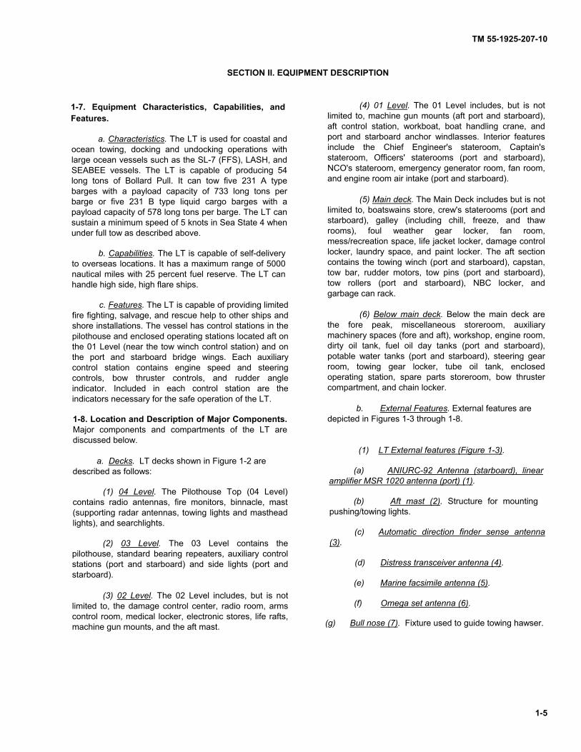
SECTION II. EQUIPMENT DESCRIPTION 1-7. Equipment Characteristics, Capabilities, and Features.
a. Characteristics. The LT is used for coastal and
ocean towing, docking and undocking operations with large ocean vessels such as the SL-7 (FFS), LASH, and SEABEE vessels. The LT is capable of producing 54 long tons of Bollard Pull. It can tow five 231 A type barges with a payload capacity of 733 long tons per barge or five 231 B type liquid cargo barges with a payload capacity of 578 long tons per barge. The LT can sustain a minimum speed of 5 knots in Sea State 4 when under full tow as described above.
b. Capabilities. The LT is capable of self-delivery
to overseas locations. It has a maximum range of 5000 nautical miles with 25 percent fuel reserve. The LT can handle high side, high flare ships.
c. Features. The LT is capable of providing limited
fire fighting, salvage, and rescue help to other ships and shore installations. The vessel has control stations in the pilothouse and enclosed operating stations located aft on the 01 Level (near the tow winch control station) and on the port and starboard bridge wings. Each auxiliary control station contains engine speed and steering controls, bow thruster controls, and rudder angle indicator. Included in each control station are the indicators necessary for the safe operation of the LT.
1-8. Location and Description of Major Components. Major components and compartments of the LT are discussed below. a. Decks. LT decks shown in Figure 1-2 are described as follows:
(1) 04 Level. The Pilothouse Top (04 Level)
contains radio antennas, fire monitors, binnacle, mast (supporting radar antennas, towing lights and masthead lights), and searchlights.
(2) 03 Level. The 03 Level contains the
pilothouse, standard bearing repeaters, auxiliary control stations (port and starboard) and side lights (port and starboard).
(3) 02 Level. The 02 Level includes, but is not
limited to, the damage control center, radio room, arms control room, medical locker, electronic stores, life rafts, machine gun mounts, and the aft mast.
(4) 01 Level. The 01 Level includes, but is not
limited to, machine gun mounts (aft port and starboard), aft control station, workboat, boat handling crane, and port and starboard anchor windlasses. Interior features include the Chief Engineer's stateroom, Captain's stateroom, Officers' staterooms (port and starboard), NCO's stateroom, emergency generator room, fan room, and engine room air intake (port and starboard).
(5) Main deck. The Main Deck includes but is not
limited to, boatswains store, crew's staterooms (port and starboard), galley (including chill, freeze, and thaw rooms), foul weather gear locker, fan room, mess/recreation space, life jacket locker, damage control locker, laundry space, and paint locker. The aft section contains the towing winch (port and starboard), capstan, tow bar, rudder motors, tow pins (port and starboard), tow rollers (port and starboard), NBC locker, and garbage can rack.
(6) Below main deck. Below the main deck are
the fore peak, miscellaneous storeroom, auxiliary machinery spaces (fore and aft), workshop, engine room, dirty oil tank, fuel oil day tanks (port and starboard), potable water tanks (port and starboard), steering gear room, towing gear locker, tube oil tank, enclosed operating station, spare parts storeroom, bow thruster compartment, and chain locker. b. External Features. External features are depicted in Figures 1-3 through 1-8. (1) LT External features (Figure 1-3).
(a) ANIURC-92 Antenna (starboard), linear
amplifier MSR 1020 antenna (port) (1).
(b) Aft mast (2). Structure for mounting pushing/towing lights.
(c) Automatic direction finder sense antenna
(3).
(d) Distress transceiver antenna (4).
(e) Marine facsimile antenna (5).
(f) Omega set antenna (6). (g) Bull nose (7). Fixture used to guide towing hawser.

TM 55-1925-207-10
1-6
Figure 1-2. LT Decks.

TM 55-1925-207-10
1-7
Figure 1-3. LT External Features (Sheet 1 of 4).

TM 55-1925-207-10
1-8
AFT, LOOKING UP
Figure 1-3. LT External Features (Sheet 2 of 4).

TM 55-1925-207-10
1-9
STBD LOOKING INBOARD
Figure 1-3. LT External Features (Sheet 3 of 4).