TM 55-1510-221-CL TECHNICAL MANUAL Operator's and ...
56
TM 55-1510-221-CL TECHNICAL MANUAL Operator's and Crewmember's Checklist ARMY MODEL RC-12H AIRCRAFT Pilot's Checklist This copy is a reprint which includes current pages from Change 1. "Approved for public release distribution is unlimited." HEADQUARTERS, DEPARTMENT OF THE ARMY 30 DECEMBER 1988
Transcript of TM 55-1510-221-CL TECHNICAL MANUAL Operator's and ...

TM 55-1510-221-CL
TECHNICAL MANUAL
Operator's and Crewmember's Checklist
ARMY MODEL
RC-12H
AIRCRAFT
Pilot's Checklist
This copy is a reprint which includes current pages from Change 1.
"Approved for public release distribution is unlimited."
HEADQUARTERS,DEPARTMENT OF THE ARMY
30 DECEMBER 1988
TM 55-1510-221-CLC 2
CHANGE HEADQUARTERSDEPARTMENT OF THE ARMY
NO. 2 WASHINGTON, D.C., 30 April 1993
Operator's and Crewmember's ChecklistArmy Model RC-12H Aircraft
Pilot's Checklist
DISTRIBUTION STATEMENT A : Approved for public release; distribution is unlimited.
TM 55-1510-221-CL, 30 December 1988, is changed as follows:
1. Remove and insert pages as indicated by a vertical bar in the margin. An illustration change is indicated by aminiature pointing hand.
Remove pages Insert pages
N-1 through N-4 N-1 through N-4N-7 through N-12 N-7 through N-12E-1 and E-2 E-1 and E-2P-1 through P-14 P-1 through P-13/
(P-14 blank)
2. Retain this sheet in front of manual for reference purposes.


TM 55-1510-221-CLC 1
URGENT
CHANGE HEADQUARTERSDEPARTMENT OF THE ARMY
NO. 1 WASHINGTON, D.C., 17 August 1992
Operator's and Crewmember's Checklist
Army Model RC-12H Aircraft
Pilot's Checklist
TM 55-1510-221-CL, 30 December 1988, is changed as follows:
1. Remove and insert pages as indicated below. New or changed text material is indicated by a vertical bar in themargin. An illustration change is indicated by a miniature pointing hand.
Remove pages Insert pages
N-7 through N-12 N-7 through N-12
2. Retain this sheet in front of manual for reference purposes.
DISTRIBUTION STATEMENT A: Approved for public release; distribution is unlimited.
URGENT
}

TM 55-1510-221-CLC 1
By Order of the Secretary of the Army:
GORDON R. SULLIVANGeneral, United States Army
Official: Chief of Staff
MILTON H. HAMILTONAdministrative Assistant to the
Secretary of the Army02249
DISTRIBUTION:To be distributed in accordance with DA Form 12-31-E, block no. 0994, requirements for TM 55-1510-221-CL.
TM 55-1510-221-CL
GENERAL INFORMATIONAND SCOPE
SCOPE. This checklist contains the operator's and crewmember's checks to be accomplished during normal andemergency operations.
GENERAL INFORMATION. The checklist consists of three parts: normal procedures, emergency procedures, andperformance data. Normal procedures consist of the procedures required for normal flight and those required for "BeforeLanding". The normal procedures portion will be subdivided to include the before landing checks of Chapter 8 of theOperator's Manual. Emergency procedures are subdivided into 7 classifications as follows: engine, propeller, (prop), fire,fuel, electrical (elect), landing and ditching (Idg/ dtch), and flight controls (fit cont). Performance data consists ofperformance checks.
NOTE
This checklist does not replace the amplified version of the procedures in the operator'smanual (TM 55-1510-221-10), but is a condensed version of each procedure.
NORMAL PROCEDURES PAGES. The contents of the normal procedures of this manual are a condensation of theamplified checklist appearing in the normal procedures, or crew duties portion of the applicable operator's manual.
EMERGENCY PROCEDURES PAGES. The requirements for this section of the condensed checklist manual (CL) areidentical to those for the normal procedures, except that the information is drawn from
i

TM 55-1510-221-CL
the amplified checks in the emergency procedures portion of the operator's manual. The emergency requirements aresubdivided into the 7 classifications listed above. Immediate action items shall be underlined.
Symbols preceding numbered steps.
∗ Indicates performance of steps is mandatory for all "Thru Flights".
N Means performance of step is mandatory for "Night Flights".
Indicates a detailed procedure for this step is included in the Performance Checks section, located at the backof the checklist.
I Indicates mandatory check for "Instrument Flights".
O - Indicates if installed.
(3) Copilot duties. To be performed at pilot's command.
Immediate action emergency items are underlined.
REPORTING ERRORS AND RECOMMENDING IMPROVEMENTSYou con help improve this manual. If you find any mistakes or if you know of a way to improve theprocedures, please let us know. Mail your letter or DA Form 2028 (Recommended Changes toPublications and Blank Forms), or DA Form 2028-2 located in the back of the applicable AircraftOperator's Manual direct to: Commander, US Army Aviation Systems Command, ATTN: AMSAV-MMD,4300 Goodfellow Blvd., St. Louis, MO 63120-1798. A reply will be furnished directly to you.
ii
TM 55-1510-221-CL
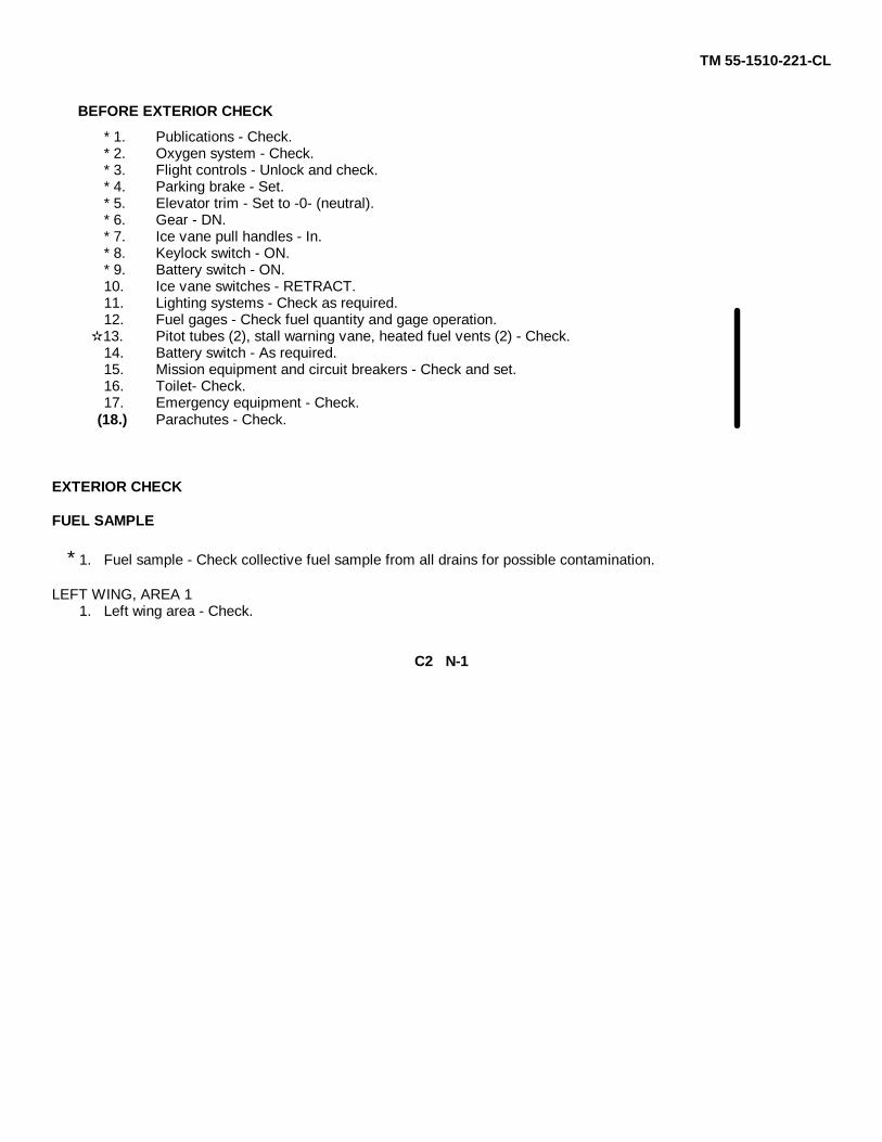
BEFORE EXTERIOR CHECK
* 1. Publications - Check.* 2. Oxygen system - Check.* 3. Flight controls - Unlock and check.* 4. Parking brake - Set.* 5. Elevator trim - Set to -0- (neutral).* 6. Gear - DN.* 7. Ice vane pull handles - In.* 8. Keylock switch - ON.* 9. Battery switch - ON.10. Ice vane switches - RETRACT.11. Lighting systems - Check as required.12. Fuel gages - Check fuel quantity and gage operation.13. Pitot tubes (2), stall warning vane, heated fuel vents (2) - Check.14. Battery switch - As required.15. Mission equipment and circuit breakers - Check and set.16. Toilet- Check.17. Emergency equipment - Check.
(18.) Parachutes - Check.
EXTERIOR CHECK
FUEL SAMPLE
* 1. Fuel sample - Check collective fuel sample from all drains for possible contamination.
LEFT WING, AREA 11. Left wing area - Check.
C2 N-1

TM 55-1510-221-CL
LEFT MAIN LANDING GEAR1. Left main landing gear - Check.
LEFT ENGINE AND PROPELLER1. Left engine - Check.
CENTER SECTION, LEFT SIDE1. Center section - Check.
FUSELAGE UNDERSIDE1. Fuselage underside - Check.
NOSE SECTION, AREA 21. Nose section - Check.
CENTER SECTION, RIGHT SIDE1. Center section - Check.
RIGHT ENGINE AND PROPELLER1. Right engine and propeller - Check.
RIGHT MAIN LANDING GEAR1. Right main landing gear - Check.
RIGHT WING, AREA 31. Right wing - Check.
FUSELAGE RIGHT SIDE, AREA 41. Fuselage right side - Check.
EMPENNAGE, AREA 51. Empennage - Check.
N-2

TM 55-1510-221-CL
FUSELAGE, LEFT SIDE, AREA 61. Fuselage - Check.
INTERIOR CHECK1. Cargo/loose equipment - Check secure.
2. Cabin/cargo doors - Test and lock.
3. Emergency exit - Check secure and key removed.
4. Mission cooling ducts - Check open and free of obstructions.
5. Flare/chaff dispenser preflight test - Completed.
6. KY-28/58 key loaded - As required.
7. Crew briefing - As required.
BEFORE STARTING ENGINES1. Oxygen system - Check as required.
2. Circuit breakers - Check in.
* 3. Overhead control panel switches - Set.
* 4. Fuel panel switches - Check.
5. Magnetic compass - Check.
* 6. Pedestal controls - Set.
* 7. Pedestal extension switches - Set.
8. Gear alternate engage and ratchet handles Stowed.
9. Outside air temperature gage - Check, note current reading.
10. Instrument panel - Check and set.
11. Deleted.
12. Mission panel switches and circuit breakers - Set and OFF.
C2 N-3
TM 55-1510-221-CL
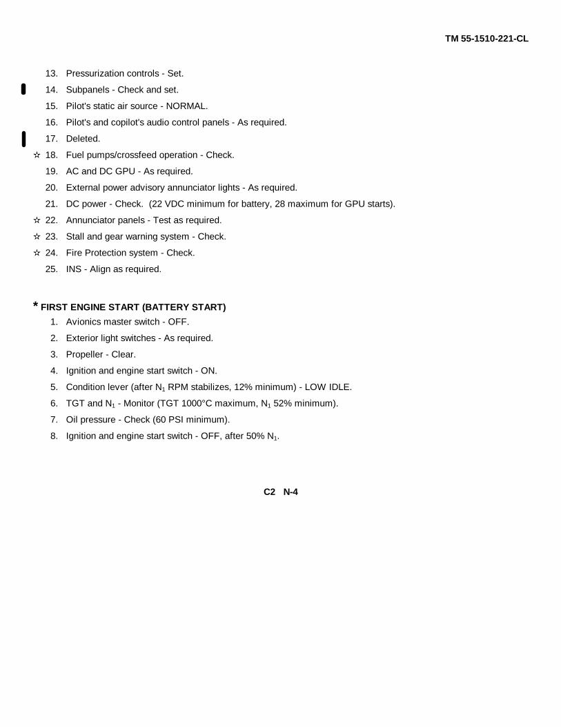
13. Pressurization controls - Set.
14. Subpanels - Check and set.
15. Pilot's static air source - NORMAL.
16. Pilot's and copilot's audio control panels - As required.
17. Deleted.
18. Fuel pumps/crossfeed operation - Check.
19. AC and DC GPU - As required.
20. External power advisory annunciator lights - As required.
21. DC power - Check. (22 VDC minimum for battery, 28 maximum for GPU starts).
22. Annunciator panels - Test as required.
23. Stall and gear warning system - Check.
24. Fire Protection system - Check.
25. INS - Align as required.
* FIRST ENGINE START (BATTERY START)
1. Avionics master switch - OFF.
2. Exterior light switches - As required.
3. Propeller - Clear.
4. Ignition and engine start switch - ON.
5. Condition lever (after N1 RPM stabilizes, 12% minimum) - LOW IDLE.
6. TGT and N1 - Monitor (TGT 1000°C maximum, N1 52% minimum).
7. Oil pressure - Check (60 PSI minimum).
8. Ignition and engine start switch - OFF, after 50% N1.
C2 N-4

TM 55-1510-221-CL
9. Condition lever - HI IDLE.
10. Generator switch - RESET, then ON.
SECOND ENGINE START (BATTERY START)1. First engine generator load - 50% or less.
2. Propeller - Clear.
3. Ignition and engine start switch - ON.
4. Condition lever (after N, RPM passes 12% minimum) - LOW IDLE.
5. TGT and N1, -Monitor (TGT 1000°C maximum N1 52% minimum).
6. Oil pressure - Check (60 PSI minimum).
7. Ignition and engine start switch - OFF after 50% N1.
8. Battery charge light - Check.
9. Inverter switches - ON, check INVERTER lights extinguished.
10. Second engine generator - RESET, then ON.
11. Condition levers - As required.
ABORT START1. Condition lever - FUEL CUTOFF.
2. Ignition and engine start switch - STARTER ONLY.
3. TGT - Monitor for drop in temperature.
4. Ignition and engine start switch - OFF.
ENGINE CLEARING1. Condition lever - FUEL CUTOFF.
N-5

TM 55-1510-221-CL
2. Ignition and engine start switch OFF (5 minute minimum).
3. Ignition and engine start switch STARTER ONLY (15 seconds minimum, 30 seconds maximum).
4. Ignition and engine start switch OFF.
∗ FIRST ENGINE START (GPU START)
1. INS As required.
2. Avionics master switch As required.
3. Exterior light switches As required.
4. Propeller Clear.
5. Ignition and engine start switch ON.
6. Condition lever (after NI, RPM stabilizes, 12% minimum) -LOW IDLE.
7. TGT and N1, -Monitor (TGT 1000°C maximum, N1 52% minimum).
8. Oil pressure Check (60 PSI minimum).
9. Ignition and engine start switch OFF after 50% N1.
10. Condition lever Hi IDLE.
11. DC GPU Disconnect as required.
12. Generator switch (GPU disconnected) RESET, then ON.
SECOND ENGINE START (GPU START)1. Propeller - Clear.
2. Ignition and engine start switch - ON.
3. Condition lever (after N1, RPM passes, 12% minimum) LOW IDLE.
4. TGT and N1 -Monitor (TGT 1000°C maximum, N1, 52% minimum).
N-6
TM 55-1510-221-CL
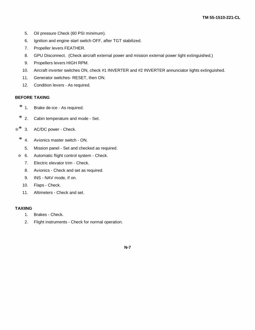
5. Oil pressure Check (60 PSI minimum).
6. Ignition and engine start switch OFF, after TGT stabilized.
7. Propeller levers FEATHER.
8. GPU Disconnect. (Check aircraft external power and mission external power light extinguished.)
9. Propellers levers HIGH RPM.
10. Aircraft inverter switches ON, check #1 INVERTER and #2 INVERTER annunciator lights extinguished.
11. Generator switches- RESET, then ON.
12. Condition levers - As required.
BEFORE TAXING
∗ 1. Brake de-ice - As required.
∗ 2. Cabin temperature and mode - Set.
∗ 3. AC/DC power - Check.
∗ 4. Avionics master switch - ON.
5. Mission panel - Set and checked as required.
6. Automatic flight control system - Check.
7. Electric elevator trim - Check.
8. Avionics - Check and set as required.
9. INS - NAV mode, if on.
10. Flaps - Check.
11. Altimeters - Check and set.
TAXIING1. Brakes - Check.
2. Flight instruments - Check for normal operation.
N-7

TM 55-1510-221-CL
ENGINE RUNUP
1. Mission control panel - Set.
2. Propeller manual feathering - Check.
3. Autofeather - Check.
4. Overspeed governors - Check.
5. Primary governors - Check.
6. Ice vanes - Check.
7. Condition levers - HI IDLE.
8. Power levers - IDLE.
9. Anti-ice and de-ice systems - Check.
10. Pneumatic pressure - Check.
11. Pressurization system - Check.
12. Condition levers - As required.
13. Windshield anti-ice - As required.
BEFORE TAKEOFF(1.) Autofeather switch - ARM.
(2.) Bleed air valves - As required.
(3.) Ice and rain switches - As required.
(4.) Fuel panel - Check fuel quantity and switch positions.
(5.) Flight and engine instruments - Check for normal indications.
(6.) Cabin altitude and rate-of-climb controller - Set.
(7.) Annunciator panels - Check (note indications).
8. Propeller levers - HIGH RPM.
9. Flaps - As required.
10. Trim - Set.
11. Avionics-Set.
C2 N-8

TM 55-1510-221-CL
12. Flight controls - Check.
(13.) Departure briefing - Complete.
LINE UP(1.) Transponder- As required.
(2.) Engine autoignition switch - ARM.
3. Power stabilized - Check approximately 25% minimum.
(4.) Condition levers - LOW IDLE.
5. Lights - As required.
6. Mission control panel - Set.
AFTER TAKEOFF1. Gear - UP.
2. Flaps - UP.
3. Landing lights - OFF.
4. Climb power- Set.
5. PROP SYNC switch - As required.
(6.) Yaw damp - As required.
(7.) Autofeather switch -As required.
(8.) Brake de-ice - As required.
(9.) Windshield anti-ice - As required.10. Cabin pressurization Check, adjust RATE control knob so that cabin rate-of-climb equals one-third aircraft rate-
of-climb.(11.) Wings and nacelles - Check.
(12.) Flare/chaff dispenser safety pin (electronic module) - Remove.
(13.) Chaff function selector switch - As required.
(14.) APR-39 and APR-44 - As required.
C2 N-9

TM 55-1510-221-CL
CRUISE1. Power - Set.
2. Ice and rain switches - As required.
(3.) Auxiliary fuel gages - Monitor.
(4.) Altimeters - Check.
(5.) Engine instrument indications - Check.
6. Recognition lights - As required.
DESCENT - MAX RATE (CLEAN)(1.) Cabin pressurization - Set.
2. Power levers - IDLE.
3. Propeller levers - HIGH RPM.
4. Flaps - UP.
5. Gear - UP.
6. Airspeed - Vmo
(7.) Ice and rain switches - As required.
8. Recognition lights - As required.
DESCENT - MAX RATE (LANDING CONFIGURATION)(1.) Cabin pressurization - Set.
2. Power levers - IDLE.
3. Propeller levers - HIGH RPM.
4. Flaps - APPROACH.
5. Gear - DN.
6. Airspeed 180 KIAS maximum.
(7.) Ice & rain switches - As required.
8. Recognition lights - As required.
N-10

TM 55-1510-221-CL
DESCENT-ARRIVAL(1.) Cabin pressurization - Set.
(2.) Ice and rain switches - As required.
(3.) Windshield anti-ice - As required.
4. Recognition lights - ON.
5. Altimeters - Set to current altimeter setting.
6. Flare/chaff dispenser arm-safe switch - SAFE.
7. Flare/chaff dispenser safety pin (electronic module) - Insert.
8. Crew briefing - Complete.
BEFORE LANDING1. Propeller synchronization switch - OFF.
(2.) Autofeather switch - ARM.
3. Propeller levers - As required.
4. Flap switch (below 198 KIAS) - APPROACH.
5. Gear- DN.
6. Landing lights - As required.
(7.) Brake de-ice - As required.
LANDING1. Autopilot and yaw damp - Disengaged.
2. Gear down lights - Check three green.
3. Propeller levers - HIGH RPM.
TOUCH-AND-GO LANDINGS(1.) Propeller levers - HIGH RPM.
(2.) Flaps - As required.
(3.) Trim - Set.
C2 N-11

TM 55-1510-221-CL
4. Power stabilized - Check approximately 25% minimum.
5. Takeoff power- Set.
GO-AROUND1. Power-As required.
2. Gear-UP.
3. Flaps - UP.
4. Landing lights - OFF.
5. Climb power-Set.
(6.) Yaw damp - As required.
(7.) Brake de-ice - OFF.
AFTER LANDING(1.) Condition levers - As required.
(2.) Engine autoignition switch - OFF.
(3.) Ice and rain switches - OFF.
(4.) Flaps - UP.
(5.) Transponder - As required.
(6.) Radar -As required.
7. Lights - As required.
(8.) Mission control panel - Set.
ENGINE SHUTDOWN1. Brake de-ice - OFF.
2. Parking brake - Set.
3. Landing/taxi lights - OFF.
4. Cabin temperature mode selector switch - OFF.
5. Autofeather switch - OFF.
C2 N-12

TM 55-1510-221-CL
6. Vent and aft vent blower switches - AUTO.
7. INS - OFF.
8. Mission equipment - OFF, as required.
9. Inverter switches - OFF.
10. Battery condition - Check as required.
11. TGT - Check.
12. Propeller levers - FEATHER.
13. Condition levers - FUEL CUTOFF.
14. Exterior lights - OFF.
15. Master panel lights switch - OFF.
16. Avionics master switch - Off.
17. Master switch - OFF.
18. Keylock switch - OFF.
19. Oxygen system - OFF.
BEFORE LEAVING AIRCRAFT1. Wheels - Chocked.
2. Parking brake - As required.
3. Flight controls - Locked.
4. Overhead flood lights - Off.
5. Standby fuel pump switches - OFF.
6. Transponder - OFF.
7. Mode 4 - As required.
8. KY-28/58 - Zeroize as required.
9. Emergency exit lock - As required.
10. Aft cabin light - OFF.
11. Door light - OFF.
12. Walk-around inspection - Complete.
N-13

TM 55-1510-221-CL
13. Aircraft forms - Complete.
14. Aircraft - secured.
N-14
TM 55-1510-221-CL
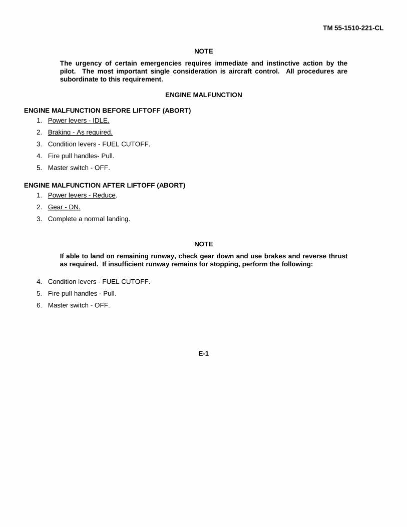
NOTE
The urgency of certain emergencies requires immediate and instinctive action by thepilot. The most important single consideration is aircraft control. All procedures aresubordinate to this requirement.
ENGINE MALFUNCTION
ENGINE MALFUNCTION BEFORE LIFTOFF (ABORT)1. Power levers - IDLE.
2. Braking - As required.
3. Condition levers - FUEL CUTOFF.
4. Fire pull handles- Pull.
5. Master switch - OFF.
ENGINE MALFUNCTION AFTER LIFTOFF (ABORT)1. Power levers - Reduce.
2. Gear - DN.
3. Complete a normal landing.
NOTE
If able to land on remaining runway, check gear down and use brakes and reverse thrustas required. If insufficient runway remains for stopping, perform the following:
4. Condition levers - FUEL CUTOFF.
5. Fire pull handles - Pull.
6. Master switch - OFF.
E-1

TM 55-1510-221-CL
ENGINE MALFUNCTION AFTER LIFTOFF (FLIGHT CONTINUED)1. Power- Maximum controllable.
2. Gear- UP.
3. Flaps- UP.
4. Landing light - OFF.
5. Brake de-ice - OFF.
6. Engine cleanup - Perform.
7. Generator load - 100% max.
ENGINE MALFUNCTION DURING FLIGHT1. Autopilot/yaw damp - DISENGAGE
2. Power- As required.
3. Dead engine - Identified.
4. Power lever (dead engine) - IDLE.
5. Propeller lever (dead engine) FEATHFR.
6. Propeller synchronization switch - OFF.
7. Gear - As required.
8. Flaps - As required.
9. Generator load - 100% max.
10. Power - Set for single engine cruise.
11. Engine cleanup - Perform.ENGINE MALFUNCTION DURING FINAL APPROACH
1. Power- As required.
2. Gear - DN.
ENGINE MALFUNCTION (SECOND ENGINE)1. Airspeed - 140 KIAS.
C2 E-2

TM 55-1510-221-CL
2. Power lever - IDLE.
3. Propeller lever - Do not FEATHER.
4. Conduct engine restart procedure.
ENGINE SHUTDOWN IN FLIGHT1. Power lever - IDLE.
2. Propeller lever - FEATHER.
3. Condition lever - FUEL CUTOFF.
4. Engine cleanup - Perform.
ENGINE CLEANUP1. Autoignition switch - OFF.
2. Autofeather switch - OFF.
3. Generator switch - OFF.
4. Propeller synchronization switch - OFF.
ENGINE RESTART DURING FLIGHT USING STARTER1. Cabin temperature mode selector switch - OFF.
2. Electrical load - Reduce to minimum.
3. Fire pull handle - In.
4. Power lever - IDLE.
5. Propeller lever - FEATHER.
6. Condition lever - FUEL CUTOFF.
7. TGT (operative engine) - 700°C or less.
8. Ignition and engine start switch - ON.
9. Condition lever - LOW IDLE.
10. TGT - Monitor (1,000°C for 5 seconds maximum).
11. Oil pressure - Check.
E-3

TM 55-1510-221-CL
12. Ignition and engine start switch - OFF at 50% N1.
13. Generator switch - RESET, then ON.
14. Engine cleanup Perform if engine restart unsuccessful.
15. Cabin temperature mode selector switch As required.
16. Electrical equipment - As required.
17. Autoignition switch - ARM.
18. Propellers - Synchronize.
19. Power - As required.
ENGINE RESTART DURING FLIGHT (NOT USING STARTER)1. Cabin temperature mode selector switch - OFF.
2. Electrical load - Reduce to minimum.
3. Generator switch (affected engine) - OFF.
4. Fire pull handle - Check in.
5. Power lever - IDLE.
6. Propeller lever - HIGH RPM.
7. Condition lever - FUEL CUTOFF.
8. Airspeed - 140 KIAS minimum.
9. Altitude below 20,000 feet - Check.
10. Engine autoignition switch - ARM.
11. Condition lever - LOW IDLE.
12. TGT - Monitor (1,000°C for 5 seconds maximum).
13. Oil pressure - Check.
14. Generator switch - RESET then ON.
15. Engine Cleanup - Perform if engine restart unsuccessful.
E-4

TM 55-1510-221-CL
16. Cabin temperature mode selector switch - As required.
17. Electrical equipment - As required.
18. Autoignition switch - ARM.
19. Propellers - Synchronized.
20. Power - As required.
LOW OIL PRESSURE1. Oil pressure below 105 PSI below 21,000 feet or 85 PSI 21,000 feet and above, torque 49% maximum.
2. Oil pressure below 60 PSI Perform engine shutdown, or land as soon as practicable using minimum power toinsure safe arrival.
CHIP DETECTOR WARNING LIGHT ILLUMINATED
If a L CHIP DETR or a R CHIP DETR warning light illuminates, and safe single-engine flight can be maintained; performengine shutdown.
DUCT OVERTEMP CAUTION ANNUNCIATOR LIGHT ILLUMINATED1. Cabin air control - In.
2. Cabin temperature mode selector switch - AUTO.
3. Cabin temperature control rheostat - Full decrease.
4. Vent blower switch - HI.
5. Cabin temperature mode selector switch - MAN COOL.
6. Manual temperature switch - DECREASE (hold).
7. Left bleed air valve switch - ENVIRO OFF.
E-5
TM 55-1510-221-CL
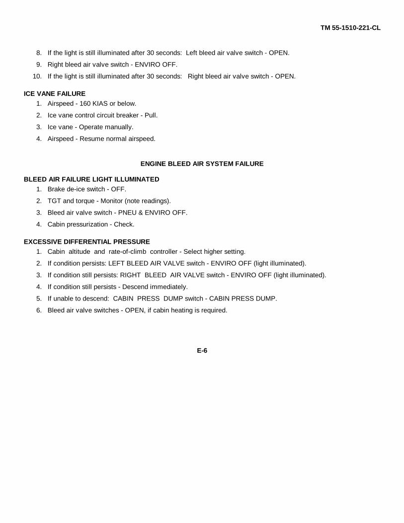
8. If the light is still illuminated after 30 seconds: Left bleed air valve switch - OPEN.
9. Right bleed air valve switch - ENVIRO OFF.
10. If the light is still illuminated after 30 seconds: Right bleed air valve switch - OPEN.
ICE VANE FAILURE1. Airspeed - 160 KIAS or below.
2. Ice vane control circuit breaker - Pull.
3. Ice vane - Operate manually.
4. Airspeed - Resume normal airspeed.
ENGINE BLEED AIR SYSTEM FAILURE
BLEED AIR FAILURE LIGHT ILLUMINATED1. Brake de-ice switch - OFF.
2. TGT and torque - Monitor (note readings).
3. Bleed air valve switch - PNEU & ENVIRO OFF.
4. Cabin pressurization - Check.
EXCESSIVE DIFFERENTIAL PRESSURE1. Cabin altitude and rate-of-climb controller - Select higher setting.
2. If condition persists: LEFT BLEED AIR VALVE switch - ENVIRO OFF (light illuminated).
3. If condition still persists: RIGHT BLEED AIR VALVE switch - ENVIRO OFF (light illuminated).
4. If condition still persists - Descend immediately.
5. If unable to descend: CABIN PRESS DUMP switch - CABIN PRESS DUMP.
6. Bleed air valve switches - OPEN, if cabin heating is required.
E-6
TM 55-1510-221-CL
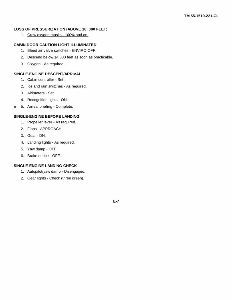
LOSS OF PRESSURIZATION (ABOVE 10, 000 FEET)1. Crew oxygen masks - 100% and on.
CABIN DOOR CAUTION LIGHT ILLUMINATED1. Bleed air valve switches - ENVIRO OFF.
2. Descend below 14,000 feet as soon as practicable.
3. Oxygen - As required.
SINGLE-ENGINE DESCENT/ARRIVAL1. Cabin controller - Set.
2. Ice and rain switches - As required.
3. Altimeters - Set.
4. Recognition lights - ON.
5. Arrival briefing - Complete.
SINGLE-ENGINE BEFORE LANDING1. Propeller lever - As required.
2. Flaps - APPROACH.
3. Gear - DN.
4. Landing lights - As required.
5. Yaw damp - OFF.
6. Brake de-ice - OFF.
SINGLE-ENGINE LANDING CHECK1. Autopilot/yaw damp - Disengaged.
2. Gear lights - Check (three green).
E-7

TM 55-1510-221-CL
3. Propeller lever (operative engine) - HIGH RPM.
SINGLE-ENGINE GO-AROUND1. Power - Maximum allowable.
2. Gear - UP.
3. Flaps - As required.
4. Landing lights - OFF.
5. Power - As required.
6. Yaw damp - As required.
PROPELLER FAILURE (OVER 2080 RPM)1. Power lever (affected engine) - IDLE.
2. Propeller lever - FEATHER.
3. Condition lever - As required.
4. Propeller synchronization - OFF.
5. Engine cleanup - As required.
FIRE
ENGINE/NACELLE FIRE DURING START OR GROUND OPERATIONS1. Propeller levers - FEATHER.
2. Condition levers - FUEL CUTOFF.
3. Fire pull handle - Pull.
4. Push to extinguish switch - Push.
5. Master switch - OFF.
ENGINE FIRE IN FLIGHT (FIRE PULL HANDLE LIGHT ILLUMINATED)1. Power lever - IDLE.
E-8

TM 55-1510-221-CL
2. If fire pull handle light out is extinguished: Advance power.
3. If fire pull handle light is still illuminated: Engine fire in flight procedures (identified) - Perform.
ENGINE FIRE IN FLIGHT (IDENTIFIED)1. Power lever - IDLE.
2. Propeller lever - FEATHER.
3. Condition lever - FUEL CUTOFF.
4. Fire pull handle - Pull.
5. Fire extinguisher - Actuate as required.
6. Engine cleanup - Perform.
FUSELAGE FIRE1. Fight the fire.
2. Land as soon as possible.
WING FIRE1. Perform engine shutdown on affected side.
2. Land as soon as possible.
ELECTRICAL FIRE1. Crew oxygen - 100%.
2. Master switch - OFF (visual conditions only).
3. All nonessential electrical equipment - OFF.
4. Battery switch - ON.
5. Generator switches (individually) - RESET, then ON.
6. Circuit breakers - Check for indication of defective circuit.
7. Essential electrical equipment - On (individually until fire source is isolated).
E-9

TM 55-1510-221-CL
8. Land as soon as practicable.SMOKE AND FUME ELIMINATION
1. Crew oxygen - 100% and ON.
2. Bleed air valve switches - ENVIRO OFF.
3. Vent blower switch - AUTO.
4. Aft vent blower switch - OFF.
5. Cabin temperature mode selector switch - OFF.
6. If smoke and fumes are not eliminated: Cabin pressure dump switch -CABIN PRESS DUMP.
7. Engine oil pressure - Monitor.
FUEL SYSTEM
FUEL PRESSURE WARNING ANNUNCIATOR LIGHT ILLUMINATED1. Standby pump switch - ON.
2. Fuel pressure warning annunciator light - Check extinguished.
3. If fuel pressure warning light is still illuminated: Record unboosted time.
NO FUEL TRANSFER CAUTION ANNUNCIATOR LIGHT ILLUMINATED1. AUX TRANSFER switch (affected side) - OVER-RIDE.
2. Auxiliary fuel quantity - Monitor.
3. AUX TRANSFER switch (after respective auxiliary fuel has completely transferred) - AUTO.
NACELLE FUEL LEAK1. Perform engine shutdown.
E-10
TM 55-1510-221-CL
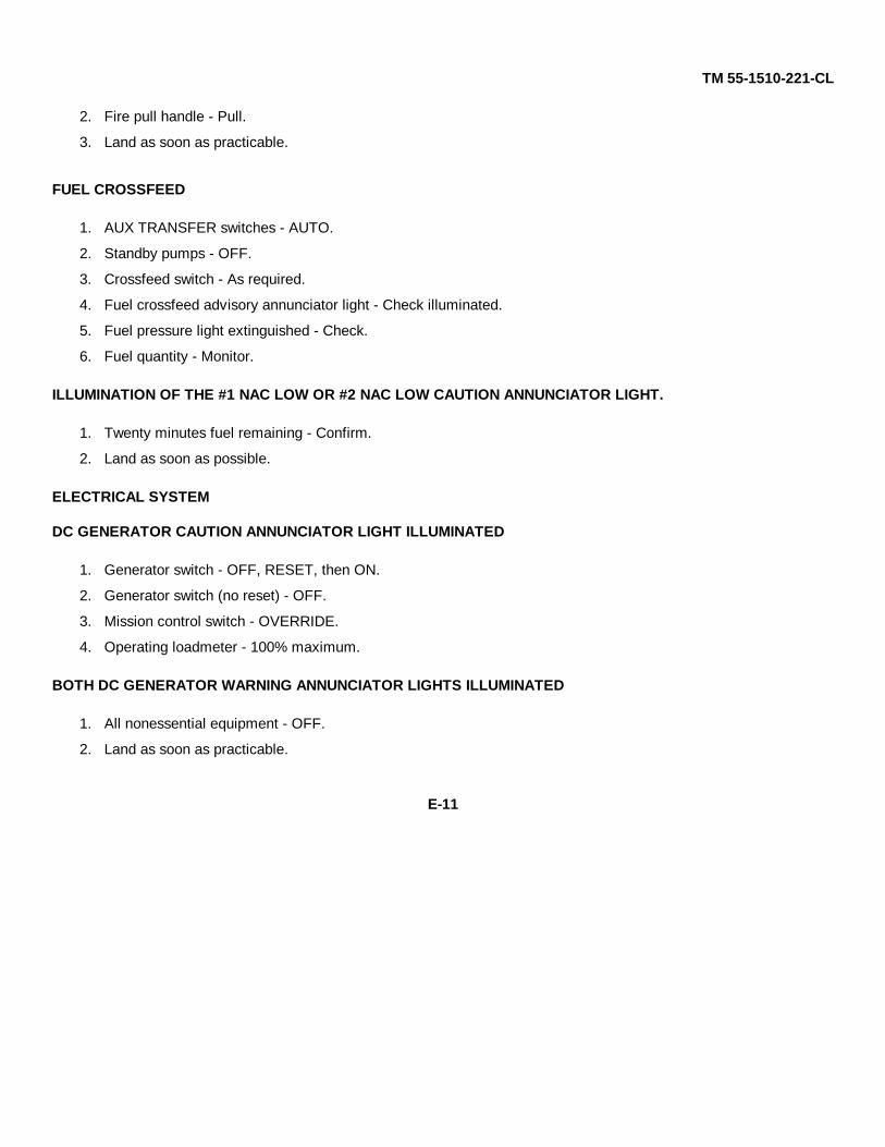
2. Fire pull handle - Pull.
3. Land as soon as practicable.
FUEL CROSSFEED
1. AUX TRANSFER switches - AUTO.
2. Standby pumps - OFF.
3. Crossfeed switch - As required.
4. Fuel crossfeed advisory annunciator light - Check illuminated.
5. Fuel pressure light extinguished - Check.
6. Fuel quantity - Monitor.
ILLUMINATION OF THE #1 NAC LOW OR #2 NAC LOW CAUTION ANNUNCIATOR LIGHT.
1. Twenty minutes fuel remaining - Confirm.
2. Land as soon as possible.
ELECTRICAL SYSTEM
DC GENERATOR CAUTION ANNUNCIATOR LIGHT ILLUMINATED
1. Generator switch - OFF, RESET, then ON.
2. Generator switch (no reset) - OFF.
3. Mission control switch - OVERRIDE.
4. Operating loadmeter - 100% maximum.
BOTH DC GENERATOR WARNING ANNUNCIATOR LIGHTS ILLUMINATED
1. All nonessential equipment - OFF.
2. Land as soon as practicable.
E-11

TM 55-1510-221-CL
EXCESSIVE LOADMETER INDICATION (OVER 100%)
1. Battery switch - OFF (monitor loadmeter).
2. Loadmeter over 100% - Nonessential electrical equipment OFF.
3. Loadmeter under 100% - BATT switch ON.
INVERTER CAUTION ANNUNCIATOR LIGHT ILLUMINATED
1. Affected #1 INVERTER or #2 INVERTER switch - OFF.
INST AC WARNING ANNUNCIATOR LIGHT ILLUMINATED
1. N1 and TGT indications - Check.
2. Other engine instruments - Monitor.
CIRCUIT BREAKER TRIPPED
1. BUS FEEDER breaker tripped - Do not reset.
2. Nonessential circuit - Do not reset.
3. Essential circuit - Reset once.
BATTERY CHARGE LIGHT ILLUMINATED.
If the BATTERY CHARGE caution light illuminates during normal cruise flight, perform the following:
1. Battery Volt-Ampmeter - Monitor. If battery current continues to increase, turn battery switch off.
2. Battery switch (landing gear/flap extension only) - ON.
EMERGENCY DESCENT
1. Power lever - IDLE.
E-12

TM 55-1510-221-CL
2. Propeller lever - HIGH RPM.
3. Flaps - APPROACH.
4. Gear - DN.
5. Airspeed - 180 KIAS maximum.
LANDING EMERGENCIES
LANDING GEAR UNSAFE INDICATION
1. Gear- DN.
2. Gear lights - Check (three green).
3. Landing gear relay circuit breaker - Check in.
LANDING GEAR EMERGENCY EXTENSION
1. Airspeed - 130 KIAS.
2. LANDING GEAR RELAY circuit breaker - Out.
3. Gear - DN.
4. Landing gear alternate engage handle - Lift and turn clockwise to the stop.
5. Alternate landing gear extension handle - Pump.
6. Gear lights - Check (three green).
GEAR-UP LANDING (ALL GEAR UP OR UNLOCKED)
1. Crew emergency briefing - Complete.
2. Loose equipment - Stowed.
3. Bleed air valves - ENVIRO OFF.
4. Cabin pressure dump switch - CABIN PRESS DUMP.
5. Cabin emergency hatch - Remove and stow.
6. Seat belts and harnesses - Secured.
E-13
TM 55-1510-221-CL
7. Landing gear alternate engage handle - Disengaged.
8. Alternate landing gear extension handle - Stowed.
9. Gear relay circuit breaker - In.
10. Gear - UP.
11. Nonessential electrical equipment - OFF.
12. Flaps - As required (DOWN for landing).
13. Power levers (runway assured) - IDLE.
14. Condition levers - FUEL CUTOFF.
15. Fire pull handles - Pull.
16. Master switch - OFF.
LANDING WITH NOSE GEAR UNSAFE
1. Crew emergency briefing - Complete.
2. Loose equipment - Stowed.
3. Bleed air valves - ENVIRO OFF.
4. Cabin pressure dump switch - CABIN PRESS DUMP.
5. Cabin emergency hatch - Remove and stow.
6. Seat belts and harnesses - Secured.
7. Nonessential electrical equipment - OFF.
8. Power levers (runway assured) - IDLE.
9. Condition levers - FUEL CUTOFF.
10. Fire pull handle - Pull.
11. Master switch - OFF.
LANDING WITH ONE MAIN GEAR UNSAFE
1. Crew emergency briefing - Complete.
2. Loose equipment - Stowed.
E-14

TM 55-1510-221-CL
3. Bleed air valve switches - ENVIRO OFF.
4. Cabin pressure dump switch - CABIN PRESS DUMP.
5. Cabin emergency hatch - Remove and stow.
6. Seat belts and harnesses - Secured.
7. Nonessential electrical equipment - OFF.
8. Touchdown - On safe main gear first.
9. Power levers (runway assured) - IDLE.
10. Condition levers - FUEL CUTOFF.
11. Fire pull handle - Pull.
12. Master switch - OFF.
CRACKED WINDSHIELD
EXTERNAL CRACK
No action is required in flight.
INTERNAL CRACK
1. Descend to below 25,000 feet.
2. Cabin Pressure - Reset pressure differential to 4 PSI or less within 10 minutes.
CRACKED CABIN WINDOW
CRACKED CABIN WINDOW (OUTER PANEL)
1. Descend to below 25,000 feet.
2. Cabin pressure - 4.6 PSI maximum.
3. Do not operate more than 20 flight hours.
CRACKED CABIN WINDOW (INNER PANEL)1. Oxygen - As required.
E-15
TM 55-1510-221-CL
2. Cabin pressure - Depressurize.
3. Descend - As required.
DITCHING
1. Radio calls/transponder - As required.
2. Crew emergency briefing - As required.
3. Bleed air valves - ENVIRO OFF.
4. Cabin pressure dump switch - CABIN PRESS DUMP.
5. Cabin emergency hatch - Remove and stow.
6. Seat belts and harnesses - Secured.
7. Gear - UP.
8. Flaps - DOWN.
9. Nonessential electrical equipment - OFF.
10. Approach - Normal, power on.
11. Emergency lights - As required.
FLIGHT CONTROLS MALFUNCTION
AUTOPILOT/YAW DAMPER EMERGENCY DISCONNECTION:
The autopilot can be disengaged by any of the following methods:
1. Pressing the DISC - TRIM - AP - YD disconnect switch (control wheels).
2. Pressing the autopilot AP ENGAGE pushbutton on the autopilot mode selector control panel.
3. Pressing the go-around switch (left power lever), (yaw damper will remain on).
4. Pulling the AP CONTR and AFCS DIRECT circuit breakers (overhead control panel).
E-16

TM 55-1510-221-CL
5. Setting AVIONICS MASTER PWR switch (overhead control panel) to the OFF position.
6. Setting aircraft MASTER switch (overhead control panel) to the OFF position.
UNSCHEDULED RUDDER BOOST ACTIVATION
1. Rudder boost - OFF. If condition persists:
2. Bleed air valve - PNEU & ENVIRO OFF.
3. Rudder trim - Adjust.
UNSCHEDULED ELECTRIC ELEVATOR TRIM
1. Elevator trim switch - OFF.
2. Elevator trim circuit breaker - Out.
BAILOUT1. Notify crew to prepare to bail out.
2. Distress message - Transmit.
3. Voice security - ZEROIZE.
4. Transponder - 7700.
5. Mode 4 - Zeroize.
6. Flaps - DOWN.
7. Airspeed - 100 KIAS.
8. Trim - As required.
9. Autopilot - Engage.
10. Cabin pressure switch - DUMP.
11. Parachute - Attach to harness.
12. Cabin door - Open.
13. Abandon the aircraft.
E-17/(E-18 blank)
TM 55-1510-221-CL
PERFORMANCE CHECKS
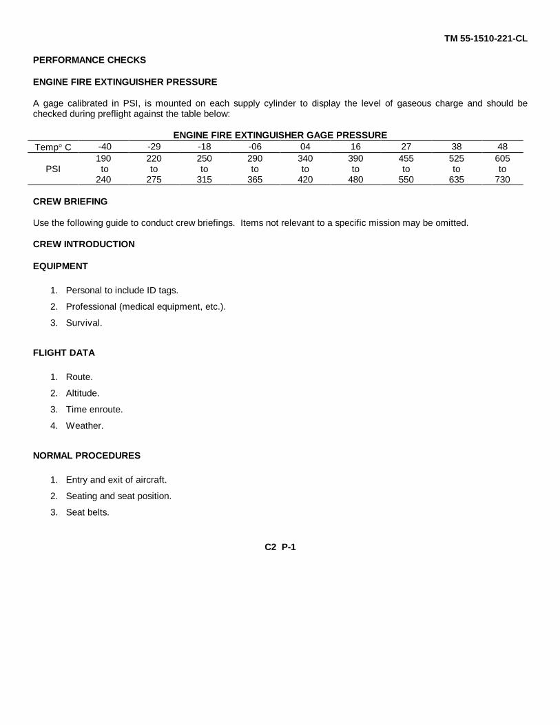
ENGINE FIRE EXTINGUISHER PRESSURE
A gage calibrated in PSI, is mounted on each supply cylinder to display the level of gaseous charge and should bechecked during preflight against the table below:
ENGINE FIRE EXTINGUISHER GAGE PRESSURETemp° C -40 -29 -18 -06 04 16 27 38 48
190 220 250 290 340 390 455 525 605PSI to to to to to to to to to
240 275 315 365 420 480 550 635 730
CREW BRIEFING
Use the following guide to conduct crew briefings. Items not relevant to a specific mission may be omitted.
CREW INTRODUCTION
EQUIPMENT
1. Personal to include ID tags.
2. Professional (medical equipment, etc.).
3. Survival.
FLIGHT DATA
1. Route.
2. Altitude.
3. Time enroute.
4. Weather.
NORMAL PROCEDURES
1. Entry and exit of aircraft.
2. Seating and seat position.
3. Seat belts.
C2 P-1

TM 55-1510-221-CL
4. Movement in aircraft.
5. Internal communications.
6. Security of equipment.
7. Smoking.
8. Oxygen.
9. Refueling.
10. Weapons and prohibited items.
11. Protective masks.
12. Toilet.
EMERGENCY PROCEDURES
1. Emergency exits.
2. Emergency equipment.
3. Emergency landing/ditching procedures.
PITOT TUBES, STALL WARNING VANE AND HEATED FUEL VENTS
1. Stall warning heat switch - ON.
2. Pitot heat switches (2) - ON. Check cover removed.
3. Fuel vent heat switches (2) - ON.
4. Left wing heated fuel vent - Check by feel for heat and condition.
5. Stall warning vane - Check by feel for heat and condition.
6. Right wing heated fuel vent - Check by feel for heat and condition.
7. Stall warning heat switch - OFF.
8. Pitot heat switches (2) - OFF.
9. Heated fuel vent switches (2) - OFF.
C2 P-2
TM 55-1510-221-CL
OXYGEN SYSTEM1. Oxygen supply pressure gages - Check.
2. Supply control lever (green) - ON.
3. Diluter control lever - 100% OXYGEN.
4. Emergency control lever (red) - Set to TEST MASK position while holding mask directly away from face, thenreturn to NORMAL.
5. Oxygen masks - Put on and adjust.
6. Emergency pressure control lever - Set to TEST MASK position and check mask for leaks, then return lever toNORMAL.
7. Flow indicator - Check. During inhalation blinker appears, during exhalation blinker disappears. Repeat aminimum of 3 times.
FUEL PUMPS/CROSSFEED OPERATION
1. Fire pull handles - Pull.
2. Standby fuel pump switches - ON.
3. Battery switch - ON.
4. #1 fuel pressure and #2 fuel pressure warning lights - Illuminated.
5. Fire pull handles - In.
6. #1 fuel press and #2 fuel press warning annunciator lights - Extinguished.
7. Standby fuel pump switches- Off.
8. #1 fuel pressure and #2 fuel pressure warning lights - Illuminated.
9. Crossfeed - Check. Check system operation by activating switch momentarily left then right, noting that #1FUEL PRESS and #2 FUEL PRESS warning annunciator lights extinguish and that the FUEL CROSS-FEEDadvisory annunciator light illuminates as switch is energized.
C2 P-3

TM 55-1510-221-CL
ANNUNCIATOR PANELS TEST
1. MASTER CAUTION, MASTER WARNING, #1 FUEL PRESS, #2 FUEL PRESS, GEAR DN, L BL AIR FAIL, RBL AIR FAIL, INST AC, #1 DC GEN, #1 INVERTER, #1 NO FUEL XFR, #2 NO FUEL XFR, #2 INVERTER, #2DC GEN, - Check illuminated.
2. ANNUNCIATOR TEST switch - Press and hold. Check that the annunciator panels, FIRE PULL handle lights,marker beacon lights, antenna azimuth indicator, MASTER CAUTION and MASTER WARNING lights areilluminated. Release switch and check that all lights except those in step 1 are extinguished.
3. MASTER CAUTION and MASTER WARNING lights - Press. Check that both lights extinguish.
STALL AND GEAR WARNING SYSTEM
1. STALL WARN TEST switch - TEST. Check that warning horn sounds.
2. LDG GEAR WARN TEST switch - TEST. Check that warning horn sounds and that the LDG GEAR CONTRhandle warning lights (2) illuminate.
FIRE PROTECTION SYSTEM
1. Fire Detector Test switch - Rotate counterclockwise to check three DETR positions. FIRE PULL handles shouldilluminate in each position. Reset MASTER WARNING in each position.
2. Fire Detector Test switch - Rotate counterclockwise to check two EXTGH positions. SQUIB OK light, associated#1 EXTGH DISCH and #2 EXTGH DISCH annunciator caution light and MASTER CAUTION LIGHT shouldilluminate in each position.
C2 P-4

TM 55-1510-221-CL
AC/DC POWER
CHECK FOR:
1. AC frequency - 394 to 406 Hz.2. AC voltage - 104 to 124 VAC.
3. DC load - Check.
4. DC voltage - 27.0 to 28.5 VDC.
AUTOMATIC FLIGHT CONTROL SYSTEMNOTE
Pause a few seconds between each step to allow time for the proper indications.
1. Set alert controller more than 1000 feet above altitude indicated on pilot's altimeter. The pilot's altimeter alertlight should be extinguished.
2. Decrease the alert controller to within 1000 feet of the pilot's altimeter setting. The alert light should illuminate.
3. Decrease the controller to less the 250 feet above the pilot's altimeter setting. The alert light should extinguish.
4. Increase the controller to 300 (50 feet above the pilot's altimeter indication) and check that the alert lightilluminates.
5. Set the desired altitude.
6. Autopilot controller UP TRIM, DN TRIM annunciators CHECK not illuminated.
CAUTION
A steady illumination of UP TRIM or DN TRIM annunciator indicates that the automaticsynchronization is not functioning and the autopilot should not be engaged.
7. Turn knob - Center.
C2 P-5

TM 55-1510-221-CL
8. Elevator trim control switch - ON.
9. Control wheel - Hold to mid travel.
10. AP button - Press. AP ENGAGE/YD ENGAGE annunciators on.
11. Deleted.
12. Deleted.
13. Control wheel - Hold aft of mid travel. Trim wheel should run nose down after approximately 3 seconds. Trimdown annunciator should illuminate after approximately 8 seconds.
14. Control wheel - Hold forward of mid travel. Trim wheel should run nose up after approximately 3 seconds, trimup annunciator should illuminate after approximately 8 seconds, and AP TRIM FAIL annunciator and MASTERWARNING flasher should illuminate after approximately 15 seconds.
WARNING
The elevator trim system must not be forced beyond the limits which are indicated on theelevator trim tab indicator.
15. AP/YD & TRIM DISC Button - Depress through second level. Autopilot and yaw damper should disengage andELECT TRIM OFF annunciator should illuminate. AP ENG and YD ENG annunciators on instrument panelshould flash 5 times.
16. Elevator trim control switch - OFF, then ON. (ELEC TRIM OFF annunciator should extinguish).
17. AP button - Re-engage.
18. Turn controller - Check that control wheel follows in each applied direction, then center.
19. Pitch wheel - Check that trim responds to pitch wheel movement. (UP TRIM and DN TRIM annunciators mayilluminate).
C2 P-6
TM 55-1510-221-CL
20. Heading bug - Center and engage HDG. Check that control follows a turn in each direction.
21. Disengage AP by selecting GA. Check that AP disengages and FD commands 7 ° nose up, wings level attitudeYD disengage, mode selector push standby.
22. Elevator trim switch - ON.
23. Pilot and Copilot trim switches - Check operation.
WARNING
Operation of the electric trim system should occur only by movement of pairs of switches.Any movement of the elevator trim wheel while depressing only one switch element denotes asystem malfunction. The electric elevator trim control switch must then be turned OFF andflight conducted by operating the elevator trim wheel manually. Do not use autopilot.
24. Pilot and Copilot. Check individual element for no movement of trim, then check proper operation of bothelements.
25. Check Pilot switches override Copilot switches while trimming in opposite directions, and trim moves in directioncommanded by Pilot.
26. Check Pilot and Copilot trim disconnects while activating trim.
27. Elevator trim switch - OFF then ON (ELECT TRIM OFF annunciator extinguishes).
PROPELLER MANUAL FEATHERING
1. Condition lever- LOW IDLE.
2. Left propeller lever - FEATHER. Check that propeller feathers.
3. Left propeller lever - HIGH RPM.
4. Repeat procedure for right propeller.
C2 P-7

TM 55-1510-221-CL
AUTOFEATHER1. Condition levers - LOW IDLE.
2. Autofeather switch - Hold to TEST. (#1 AUTOFEATHER and #2 AUTOFEATHER advisory annunciator lightsshould remain extinguished.)
3. Power levers - Advance to approximately 22% torque, then move autofeather switch to TEST. Both #1AUTOFEATHER and #2 AUTOFEATHER advisory annunciator lights should illuminate.
4. Left power lever - Retard.
a. At approximately 16 to 21% torque, check #2 AUTOFEATHER advisory annunciator extinguished.
b. At approximately 9 to 14% torque, check #1 AUTOFEATHER advisory annunciator lightextinguished. (Left propeller starts to feather.)
5. Left power lever - Set approximately 22% torque.
6. Repeat steps 1 through 4 for right engine.OVERSPEED GOVERNORS
1. Power levers - Set approximately 1950 RPM (both engines).
2. #1 propeller governor test switch - Hold to TEST position.
3. #1 propeller RPM 1830 to 1910 - Check.
4. Repeat steps 2 and 3 for #2 engine.
5. Power levers - Set 1800 RPM.
C2 P-8

TM 55-1510-221-CL
PRIMARY GOVERNORS1. Power levers - Set 1800 RPM.
2. Propeller levers - Move aft to detent. Check that propeller RPM drops to 1600 to 1640 RPM.
3. Propeller levers - HIGH RPM.ICE VANES
1. Ice vane switches - EXTEND. Verify torque drop, TGT increase, and #1 ICE VANE EXTEND and #2 ICE VANEEXTEND annunciators illuminate.
2. Ice vane switches - RETRACT. Verify return to original torque and TGT, and that #1 ICE VANE EXTEND and #2ICE VANE EXTEND annunciators extinguish.
ANTI-ICE AND DE-ICE SYSTEMS1. Windshield anti-ice switches - NORMAL and Hi. Check PILOT and COPILOT (individually) for loadmeter rise,
then OFF.
2. Propeller switches - INNER and OUTER (momentarily). Check for loadmeter rise.
3. Surface de-ice switch - SINGLE CYCLE AUTO. Check for a drop in pneumatic pressure and wing de-ice bootinflation and after 6 seconds for a second drop in pneumatic pressure.
4. Surface de-ice switch - MANUAL. Check that surface boots inflate, and remain inflated, then OFF.
5. Antenna de-ice switch - SINGLE. Check for a drop in pneumatic pressure and antenna de-ice boot inflation.
6. Antenna de-ice switch - MANUAL. Check that boots inflate, and remain inflated, then OFF.
C2 P-9

TM 55-1510-221-CL
7. Engine inlet lip heat switches - ON. Check that #1 LIP HEAT ON and #2 LIP HEAT ON advisory annunciatorlights are illuminated, and the #1 LIP HEAT and #2 LIP HEAT caution annunciator lights are extinguished, thenOFF.
8. RADOME anti-ice switch ON. Check that RADOME HEAT annunciator is illuminated, then OFF.
PNEUMATIC PRESSURE
1. Left bleed air valve switch - PNEU & ENVIRO OFF.
2. Pneumatic pressure - Check 12 to 20 PSI.
3. Right pneumatic and environmental switch - PNEU & ENVIRO OFF. Check that L BL AIR FAIL and R BL AIRFAIL annunciator lights, and L BL AIR OFF and R BL AIR OFF annunciator lights are illuminated.
4. Pneumatic pressure Verify zero.
5. Left pneumatic and environmental switches OPEN. Check that L BL AIR FAIL and R BL AIR FAIL annunciatorlights, and L BL AIR OFF and R BL AIR OFF annunciator lights are extinguished.
6. Pneumatic pressure - Verify 12 to 20 PSI.
7. Right Pneumatic and environmental switches - OPEN.
PRESSURIZATION SYSTEM
1. Cabin door caution light - Check extinguished.
2. Storm windows - Check closed.
3. Bleed air valve switches - Check OPEN.
4. Cabin altitude - Set 500 feet lower than airfield elevation.
C2 P-10
TM 55-1510-221-CL
5. Cabin pressure/dump switch - TEST (hold).
6. Cabin rate-of-climb gage - Check for descending indication and, when confirmed, release cabin pressure/dumpswitch from TEST.
7. Aircraft altitude - Set to planned cruise altitude plus 500 feet. (If this setting does not result in a CABIN ALTindication of at least 500 feet over takeoff field pressure altitude, adjust as required.)
8. Rate control - Set between 9 and 12 o'clock.
DEPARTURE BRIEFING
ATC CLEARANCE - REVIEW
1. Routing.
2. Initial altitude.
DEPARTURE PROCEDURE - REVIEW
1. SID.
2. Noise abatement procedure.
3. VFR departure route.
COPILOT DUTIES - REVIEW
1. Adjust takeoff power.
2. Monitor engine instruments.
3. Power check at 65 knots.
4. Call out engine malfunctions.
5. Tune/ident all nav/com radios.
6. Make all radio calls.
7. Adjust transponder and radar as required.
8. Complete flight log during flight (note altitudes and headings).
C2 P-11

TM 55-1510-221-CL
9. Note departure time.
PPC - REVIEW
1. Takeoff power.
2. Vr.
3. Vy (climb to 500' AGL).
4. Vyse.
ARRIVAL BRIEFING
WEATHER/ALTIMETER SETTING
AIRFIELD/FACILITIES REVIEW
1. Field elevation.
2. Runway length.
3. Runway condition.
APPROACH PROCEDURE - REVIEW
1. Approach plan/profile.
2. Altitude restrictions.
3. Missed approach.
a. Point.
b. Time.
c. Intentions.
4. Decision height or MDA.
5. Lost communications.
BACK UP APPROACH/FREQUENCIES
C2 P-12
TM 55-1510-221-CL
COPILOT DUTIES - REVIEW
1. Nav/Com set-up.
2. Monitor altitude and airspeeds.
3. Monitor approach.
4. Call out visual/field in sight.
LANDING PERFORMANCE DATA- REVIEW
1. Approach speed.
2. Runway required.
U. S. GOVERNMENT PRINTING OFFICE: 1993 - 755-120/60184
C2 P-13/(P-14 blank)
TM 55-1510-221-CL
By Order of the Secretary of the Army:
CARL E. VUONO,General, United States Army
Chief of Staff
Official:
WILLIAM J.MEEHAN IIBrigadier General, United States Army
The Adjutant General
DISTRIBUTION:
To be distributed in accordance with DA Form 12-31, -10 & CL Maintenance requirements for RC-12H Airplane,Reconnaissance.

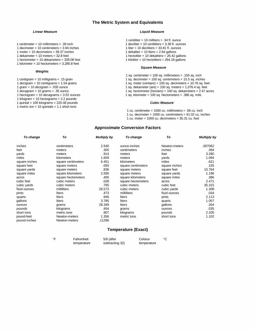
The Metric System and Equivalents
Linear Measure Liquid Measure
1 centiliter = 10 milliters = .34 fl. ounce1 centimeter = 10 millimeters = .39 inch 1 deciliter = 10 centiliters = 3.38 fl. ounces1 decimeter = 10 centimeters = 3.94 inches 1 liter = 10 deciliters = 33.81 fl. ounces1 meter = 10 decimeters = 39.37 inches 1 dekaliter = 10 liters = 2.64 gallons1 dekameter = 10 meters = 32.8 feet 1 hectoliter = 10 dekaliters = 26.42 gallons1 hectometer = 10 dekameters = 328.08 feet 1 kiloliter = 10 hectoliters = 264.18 gallons1 kilometer = 10 hectometers = 3,280.8 feet
Square MeasureWeights
1 sq. centimeter = 100 sq. millimeters = .155 sq. inch1 centigram = 10 milligrams = .15 grain 1 sq. decimeter = 100 sq. centimeters = 15.5 sq. inches1 decigram = 10 centigrams = 1.54 grains 1 sq. meter (centare) = 100 sq. decimeters = 10.76 sq. feet1 gram = 10 decigram = .035 ounce 1 sq. dekameter (are) = 100 sq. meters = 1,076.4 sq. feet1 decagram = 10 grams = .35 ounce 1 sq. hectometer (hectare) = 100 sq. dekameters = 2.47 acres1 hectogram = 10 decagrams = 3.52 ounces 1 sq. kilometer = 100 sq. hectometers = .386 sq. mile1 kilogram = 10 hectograms = 2.2 pounds1 quintal = 100 kilograms = 220.46 pounds Cubic Measure1 metric ton = 10 quintals = 1.1 short tons
1 cu. centimeter = 1000 cu. millimeters = .06 cu. inch1 cu. decimeter = 1000 cu. centimeters = 61.02 cu. inches1 cu. meter = 1000 cu. decimeters = 35.31 cu. feet
Approximate Conversion Factors
To change To Multiply by To change To Multiply by
inches centimeters 2.540 ounce-inches Newton-meters .007062feet meters .305 centimeters inches .394yards meters .914 meters feet 3.280miles kilometers 1.609 meters yards 1.094square inches square centimeters 6.451 kilometers miles .621square feet square meters .093 square centimeters square inches .155square yards square meters .836 square meters square feet 10.764square miles square kilometers 2.590 square meters square yards 1.196acres square hectometers .405 square kilometers square miles .386cubic feet cubic meters .028 square hectometers acres 2.471cubic yards cubic meters .765 cubic meters cubic feet 35.315fluid ounces milliliters 29,573 cubic meters cubic yards 1.308pints liters .473 milliliters fluid ounces .034quarts liters .946 liters pints 2.113gallons liters 3.785 liters quarts 1.057ounces grams 28.349 liters gallons .264pounds kilograms .454 grams ounces .035short tons metric tons .907 kilograms pounds 2.205pound-feet Newton-meters 1.356 metric tons short tons 1.102pound-inches Newton-meters .11296
Temperature (Exact)
°F Fahrenheit 5/9 (after Celsius °Ctemperature subtracting 32) temperature

PIN: 065800-000

This fine document...
Was brought to you by me:
Liberated Manuals -- free army and government manuals
Why do I do it? I am tired of sleazy CD-ROM sellers, who take publicly available information, slap “watermarks” and other junk on it, and sell it. Those masters of search engine manipulation make sure that their sites that sell free information, come up first in search engines. They did not create it... They did not even scan it... Why should they get your money? Why are not letting you give those free manuals to your friends?
I am setting this document FREE. This document was made by the US Government and is NOT protected by Copyright. Feel free to share, republish, sell and so on.
I am not asking you for donations, fees or handouts. If you can, please provide a link to liberatedmanuals.com, so that free manuals come up first in search engines:
<A HREF=http://www.liberatedmanuals.com/>Free Military and Government Manuals</A>
– SincerelyIgor Chudovhttp://igor.chudov.com/
– Chicago Machinery Movers