TM 5-4330-263-13&P - Liberated · PDF fileFILTER/SEPARATOR, LIQUID FUEL, 50-GPM (NSN ... (NSN...
109
TM 5-4330-263-13&P TECHNICAL MANUAL OPERA TOR AND FIELD MAINTENANCE MANUAL WITH REPAIR P ARTS AND SPECIAL TOOLS LIST FOR FILTER/SEPARATOR, LIQUID FUEL, 50-GPM (NSN 4330-01-483-1068) 100-GPM (NSN 4330-01-525-3659) 350-GPM (NSN 4330-01-529-0584) DISTRIBUTION STATEMENT A. Approved for public release; distribution is unlimited. HEADQUARTERS, DEP ARTMENT OF THE ARMY July 2008
Transcript of TM 5-4330-263-13&P - Liberated · PDF fileFILTER/SEPARATOR, LIQUID FUEL, 50-GPM (NSN ... (NSN...
TM 5-4330-263-13&P
TECHNICAL MANUALOPERATOR AND FIELD MAINTENANCE MANUALWITH REPAIR PARTS AND SPECIAL TOOLS LIST
FOR
FILTER/SEPARATOR, LIQUID FUEL,50-GPM (NSN 4330-01-483-1068)
100-GPM (NSN 4330-01-525-3659) 350-GPM (NSN 4330-01-529-0584)
DISTRIBUTION STATEMENT A. Approved for public release; distribution is unlimited.
HEADQUARTERS, DEPARTMENT OF THE ARMY July 2008

TM 5-4330-263-13&P
a
WARNING SUMMARY
In normal operation, the filter/separator is filled with diesel/jet fuel. Diesel/jet fuel may explode if subjectedto high temperatures, sources of ignition or high pressure. Keep all open flames, cigarettes, and any othersources of fire/flame or ignition a minimum of 50 yards from any fuel servicing operations. Failure tofollow this warning may result in injury or death to personnel.
Rapid filling of the filter/separator can cause a buildup of static electricity, leading to possible explosion.Fill filter/separator units slowly to minimize static buildup. Failure to follow this warning may result ininjury or death to personnel.
Diesel/jet fuel is toxic and can severely affect skin, eyes and the respiratory tract. Personnel must wearappropriate hand and eye protection (nitrile gloves and goggles). Wash skin thoroughly with soap and waterif exposed. In case of contact with diesel/jet fuel, flush eyes with clear water for at lest 15 minutes . Failureto follow this warning may result in injury or death to personnel.
Diesel/jet fuel fumes are toxic in high concentrations. Avoid prolonged breathing of vapors. Operation andmaintenance of the filter/separator should be performed only in a well-ventilated environment. Failure tofollow this warning may result in injury or death to personnel.
Failure to properly ground the filter/separator units can cause a buildup of static electricity, leading topossible explosionl. Always verify that the grounding rod is properly configured to dissipate static electric-ity. Failure to follow this warning may result in injury or death to personnel.
Failure to properly torque the lid bolts on the 350-GPM filter/separator unit can cause fuel leaks, leading topossible explosion. Failure to follow this warning may result in injury or death to personnel.
Failure to properly seat the v-band and torque the bolt securing the v-band on the 50-GPM and 100-GPMfilter/separator units can cause fuel leaks, leading to possible explosion. Follow maintenance procedurescarefully to ensure that v-band is properly seated. Failure to follow this warning may result in injury ordeath to personnel.
TM 5-4330-263-13&P
b
Improper installation of o-rings and gaskets when repairing the filter/separator units can cause fuelleaks, leading to possible explosion. Follow inspection and maintenance procedures carefully to ensureintegrity of o-rings and gaskets. Failure to follow this warning may result in injury or death to person-nel.
Exceeding the maximum pressure limits for the filter/separator units can cause fuel leaks, leading topossible explosion. Do not exceed a static pressure of 115 psi in the 50-GPM or 100-GPM filter/separator units. Failure to follow this warning may result in injury or death to personnel.
Exceeding the maximum pressure limits for the filter/separator units can cause fuel leaks, leading topossible explosion. Do not exceed a static pressure of 225 psi in the 350-GPM filter/separator unit.Failure to follow this warning may result in injury or death to personnel.
Rapid closure of downstream valves or nozzles during fueling with a high-pressure pump can result inoverpressurization of vessel and cause fuel leaks, leading to possible explosion. Failure to follow thiswarning may result in injury or death to personnel.
Avoid prolonged breathing of vapors. Only use the filter/separator in a well-ventilated environment.
Removing head assembly requires a two-man lift to avoid injury to personnel.
TM 5-4330-263-13&P
A/(B blank)
LIST OF EFFECTIVE PAGES
Dates of issue for original pages is:
Original 0 . . . . . . 31 July 2008
Total number of pages in this publication is 100 consisting of the following:
Page *ChangeNo. No.
Title . . . . . . . . . . . . . . . . . . . .0Warnings . . . . . . . . . . . . . . . .0i-ii . . . . . . . . . . . . . . . . . . . . .0WP 0001 00 (2 pages) . . . . .0WP 0002 00 (10 pages) . . . .0WP 0003 00 (2 pages) . . . . .0WP 0004 00 (2 pages) . . . . .0WP 0005 00 (2 pages) . . . . .0WP 0006 00 (4 pages) . . . . .0WP 0007 00 (2 pages) . . . . .0WP 0008 00 (2 pages) . . . . .0WP 0009 00 (6 pages) . . . . .0WP 0010 00 (4 pages) . . . . .0WP 0011 00 (4 pages) . . . . .0WP 0012 00 (2 pages) . . . . .0WP 0013 00 (2 pages) . . . . .0WP 0014 00 (2 pages) . . . . .0WP 0015 00 (2 pages) . . . . .0WP 0016 00 (2 pages) . . . . .0WP 0017 00 (4 pages) . . . . .0WP 0018 00 (4 pages) . . . . .0WP 0019 00 (10 pages) . . . .0WP 0020 00 (4 pages) . . . . .0WP 0021 00 (4 pages) . . . . .0WP 0022 00 (2 pages) . . . . .0WP 0023 00 (2 pages) . . . . .0
*Zero in this column indicates an original page

TM 5-4330-263-13&P
HEADQUARTERS, DEPARTMENT OF THE ARMY
WASHINGTON, D.C. 31 JULY 2008
TECHNICAL MANUAL
OPERATION AND FIELD MAINTENANCE WITHREPAIR PARTS AND SPECIAL TOOLS LIST
FILTER/SEPARATOR, LIQUID FUELS,50-GPM (NSN 4330-01-483-1068)
150-GPM (NSN 4330-01-525-3659)350-GPM (NSN 4330-01-529-0584)
DISTRIBUTION STATEMENT A. Approved for public release; distribution is unlimited.
i
CURRENT AS OF 2 JULY 2008
REPORTING ERRORS AND RECOMMENDING IMPROVEMENTS
You can help improve this publication. If you find any errors or if you would like to recommend any improvements to the procedures in this publication, please let us know. The preferred method is to submit your DA Form 2028 (Recommended Changes to Publications and Blank Forms) through the Internet on the Army Electronic Product Support (AEPS) Web site. The Internet address is https://aeps.ria.army.mil. The DA Form 2028 is located under the Public Applications section on the AEPS public home page. Fill out the form and click on SUBMIT. Using this form on the AEPS site will enable us to respond to your comments quicker and to manage the DA Form 2028 program better. You may also mail, e-mail, or fax your comments or DA Form 2028 directly to the U.S. Army TACOM Life Cycle Management Command. The postal address is U.S. Army TACOM Life Cycle Management Command, ATTN: AMSTA-LC-LMPP / TECH PUBS, 1 Rock Island Arsenal, Rock Island, IL 61299-7630. The e-mail address is [email protected]. The fax number is DSN 793-0726 or Commercial (309) 782-0726.
TM 5-4330-263-13&P
ii
TABLE OF CONTENTSWP Sequence No.
WARNING SUMMARY. . . . . . . . . . . . . . . . . . . . . . . . . . . . . . . . . . . . . . . . . . . . . . . . . . . . . . . . . . . . . . . . . . . . . . . . . . . a
LIST OF EFFECTIVE PAGES . . . . . . . . . . . . . . . . . . . . . . . . . . . . . . . . . . . . . . . . . . . . . . . . . . . . . . . . . . . . . . . . . . . . . .A
TITLE PAGE. . . . . . . . . . . . . . . . . . . . . . . . . . . . . . . . . . . . . . . . . . . . . . . . . . . . . . . . . . . . . . . . . . . . . . . . . . . . . .. . . . . .i
HOW TO USE THIS MANUAL . . . . . . . . . . . . . . . . . . . . . . . . . . . . . . . . . . . . . . . . . . . . . . . . . . . . . . . . . . . . . . . . . . . .iii
General Information . . . . . . . . . . . . . . . . . . . . . . . . . . . . . . . . . . . . . . . . . . . . . . . . . . . . . . . . . . . . . . . . . . . . . . . . .0001 00Description and Data . . . . . . . . . . . . . . . . . . . . . . . . . . . . . . . . . . . . . . . . . . . . . . . . . . . . . . . . . . . . . . . . . . . . . . . . .0002 00Controls and Indicators . . . . . . . . . . . . . . . . . . . . . . . . . . . . . . . . . . . . . . . . . . . . . . . . . . . . . . . . . . . . . . . . . . . . . . .0003 00Operator Preventive Maintenance Checks and Services . . . . . . . . . . . . . . . . . . . . . . . . . . . . . . . . . . . . . . . . . . . . . .0004 00Preparation for Operation . . . . . . . . . . . . . . . . . . . . . . . . . . . . . . . . . . . . . . . . . . . . . . . . . . . . . . . . . . . . . . . . . . . . .0005 00Operation . . . . . . . . . . . . . . . . . . . . . . . . . . . . . . . . . . . . . . . . . . . . . . . . . . . . . . . . . . . . . . . . . . . . . . . . . . . . . . . . . .0006 00Field Preventive Maintenance Checks and Services . . . . . . . . . . . . . . . . . . . . . . . . . . . . . . . . . . . . . . . . . . . . . . . . .0007 00Troubleshooting. . . . . . . . . . . . . . . . . . . . . . . . . . . . . . . . . . . . . . . . . . . . . . . . . . . . . . . . . . . . . . . . . . . . . . . . . . . . .0008 00Element Replacement . . . . . . . . . . . . . . . . . . . . . . . . . . . . . . . . . . . . . . . . . . . . . . . . . . . . . . . . . . . . . . . . . . . . . . . .0009 00Sight Gauge Replacement . . . . . . . . . . . . . . . . . . . . . . . . . . . . . . . . . . . . . . . . . . . . . . . . . . . . . . . . . . . . . . . . . . . . .0010 00Differential Pressure Gauge Replacement. . . . . . . . . . . . . . . . . . . . . . . . . . . . . . . . . . . . . . . . . . . . . . . . . . . . . . . . . 0011 00Fuel and Water Drain Valve Replacement. . . . . . . . . . . . . . . . . . . . . . . . . . . . . . . . . . . . . . . . . . . . . . . . . . . . . . . . .0012 00Purge Valve Replacement . . . . . . . . . . . . . . . . . . . . . . . . . . . . . . . . . . . . . . . . . . . . . . . . . . . . . . . . . . . . . . . . . . . . .0013 00Bayonet Replacement . . . . . . . . . . . . . . . . . . . . . . . . . . . . . . . . . . . . . . . . . . . . . . . . . . . . . . . . . . . . . . . . . . . . . . . .0014 00Camlock Replacement . . . . . . . . . . . . . . . . . . . . . . . . . . . . . . . . . . . . . . . . . . . . . . . . . . . . . . . . . . . . . . . . . . . . . . . .0015 00References . . . . . . . . . . . . . . . . . . . . . . . . . . . . . . . . . . . . . . . . . . . . . . . . . . . . . . . . . . . . . . . . . . . . . . . . . . . . . . . . .0016 00Maintenance Allocation Chart Introduction . . . . . . . . . . . . . . . . . . . . . . . . . . . . . . . . . . . . . . . . . . . . . . . . . . . . . . .0017 00Maintenance Allocation Chart (MAC) . . . . . . . . . . . . . . . . . . . . . . . . . . . . . . . . . . . . . . . . . . . . . . . . . . . . . . . . . . .0018 00Repair Parts and Special Tools List (RPSTL) . . . . . . . . . . . . . . . . . . . . . . . . . . . . . . . . . . . . . . . . . . . . . . . . . . . . . .0019 00Components of End Item and Basic Issue Items Lists . . . . . . . . . . . . . . . . . . . . . . . . . . . . . . . . . . . . . . . . . . . . . . .0020 00Additional Authorization List . . . . . . . . . . . . . . . . . . . . . . . . . . . . . . . . . . . . . . . . . . . . . . . . . . . . . . . . . . . . . . . . . .0021 00Expendable and Durable Items List. . . . . . . . . . . . . . . . . . . . . . . . . . . . . . . . . . . . . . . . . . . . . . . . . . . . . . . . . . . . . .0022 00Mandatory Replacement Parts. . . . . . . . . . . . . . . . . . . . . . . . . . . . . . . . . . . . . . . . . . . . . . . . . . . . . . . . . . . . . . . . . .0023 00

TM 5-4330-263-13&Pi
iii/(iv blank)
HOW TO USE THIS MANUAL
OVERVIEW
This technical manual describes operation, maintenance and repair requirements for the filter/separator units. The manual hasbeen prepared in work package format. Each work package is intended as a stand-alone unit, providing specific informationand instructions for a single topic or task. Each work package lists tools and expendable items required for the procedurescontained in that work package.
To use the maintenance work packages in this manual properly, you should familiarize yourself with the entire work package before beginning the maintenance task. Information in this manual is divided into 24 work packages and an index. Work pack-ages are numbered sequentially.
CONTENTS
WP No. Title Description0001 00 General Information General information about the manual and equipment0002 00 Description and Data Location and description of major components and
equipment specifications0003 00 Controls and Indicators Description of all operator controls and their functions0004 00 Operator Preventive Maintenance Checks and
ServicesPMCS table for equipment operators
0005 00 Preparation for Operation Procedures to prepare the units for use0006 00 Operation Operating procedures for unit0007 00 Field Preventive Maintenance Checks and Services Field-level PMCS table0008 00 Troubleshooting Steps for diagnosing and correcting problems with the
units0009 00 Fuel Draining Procedures for draining fuel from units0010 00 Element Replacement Procedures for replacing defective filter elements0011 00 Sight Gauge Replacement Procedures for replacing defective sight gauge0012 00 Differential Pressure Gauge Replacement Procedures for replacing defective differential
pressure gauge0013 00 Fuel and Water Drain Valve Replacement Procedures for replacing defective drain valve0014 00 Purge Valve Replacement Procedures for replacing defective purge valve0015 00 Bayonet Replacement Procedures for replacing defective bayonet0016 00 Camlock Replacement Procedures for replacing defective camlock0017 00 References List of documents referenced in this manual0018 00 Maintenance Allocation Chart Introduction Introduction to the MAC chart0019 00 Maintenance Allocation Chart (MAC) MAC charts for the units0020 00 Repair Parts and Special Tools List (RPSTL) Illustrated parts list0021 00 Components of End Item and Basic Issue Items Lists List of items shipped with the units0022 00 Additional Authorization List Additional equipment authorized to be used with units0023 00 Expendable and Durable Items List List of consumable materials and items used in
maintaining the units0024 00 Mandatory Replacement Parts List of parts that must be replaced during maintenance
procedures

TM 5-4330-263-13&P 0001 00
0001 00-1
OPERATOR AND FIELD MAINTENANCEFILTER/SEPARATOR, LIQUID FUEL, 50-, 100-, AND 350-GPM
GENERAL INFORMATION
SCOPE
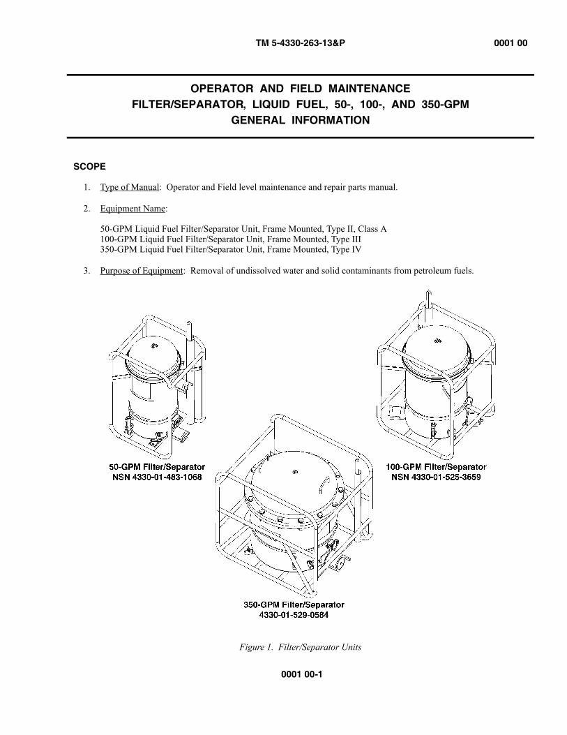
1. Type of Manual: Operator and Field level maintenance and repair parts manual.
2. Equipment Name:
50-GPM Liquid Fuel Filter/Separator Unit, Frame Mounted, Type II, Class A100-GPM Liquid Fuel Filter/Separator Unit, Frame Mounted, Type III350-GPM Liquid Fuel Filter/Separator Unit, Frame Mounted, Type IV
3. Purpose of Equipment: Removal of undissolved water and solid contaminants from petroleum fuels.
Figure 1. Filter/Separator Units
TM 5-4330-263-13&P 0001 00
0001 00-2
MAINTENANCE FORMS AND RECORDS
Department of the Army forms and procedures used for equipment maintenance will be those prescribed by (as applicable) DAPAM738-750, Functional Users Manual for The Army Maintenance Management System (TAMMS); DA PAM738-751, Functional Users Manual for the Army Maintenance Management System- Aviation (TAMMS-A); or AR 700-138, Army Logistics Readiness and Sustainability.
REPORTING EQUIPMENT IMPROVEMENT RECOMMENDATION (EIR)
If your filter/separator needs improvement, let us know. Send us an EIR. You, the user, are the only one who can tell us what you don’t like about your equipment. Let us know why you don’t like the design or performance. Put it on an SF 368 (Prod-uct Quality Deficiency Report). Mail it to the address specified in DA PAM738-750, or as specified by the contracting activ-ity. We will send you a reply.
CORROSION PREVENTION AND CONTROL
Corrosion Prevention and Control (CPC) of Army materiel is a continuing concern. It is important that any corrosion prob-lems with this item be reported so that the problem can be corrected and improvements can be made to prevent the problem in future items.
While corrosion is typically associated with rusting of metals , it can also include deterioration of other materials, such as rubber and plastic. Unusual cracking, softening, swelling, or breaking of these materials may be a corrosion problem.
If a corrosion problem is identified, it can be reported using SF 368, Product Quality Deficiency Report. Use of key words such as corrosion , rust , deterioration , or cracking will ensure that the information is identified as a CPC problem. The formshould be submitted to the address specified in DA PAM738-750.
DESTRUCTION OF ARMY MATERIEL TO PREVENT ENEMY USE
For procedures to destroy this equipment to prevent its use by the enemy, refer to TM750-244-2, Procedures for Destruction of Materiel to Prevent Enemy Use.
END OF WORK PACKAGE
0001 00
TM 5-4330-263-13&P 0002 00
0002 00-1
OPERATOR AND FIELD MAINTENANCEFILTER/SEPARATOR, LIQUID FUEL, 50-, 100-, AND 350-GPM
DESCRIPTION AND DATA
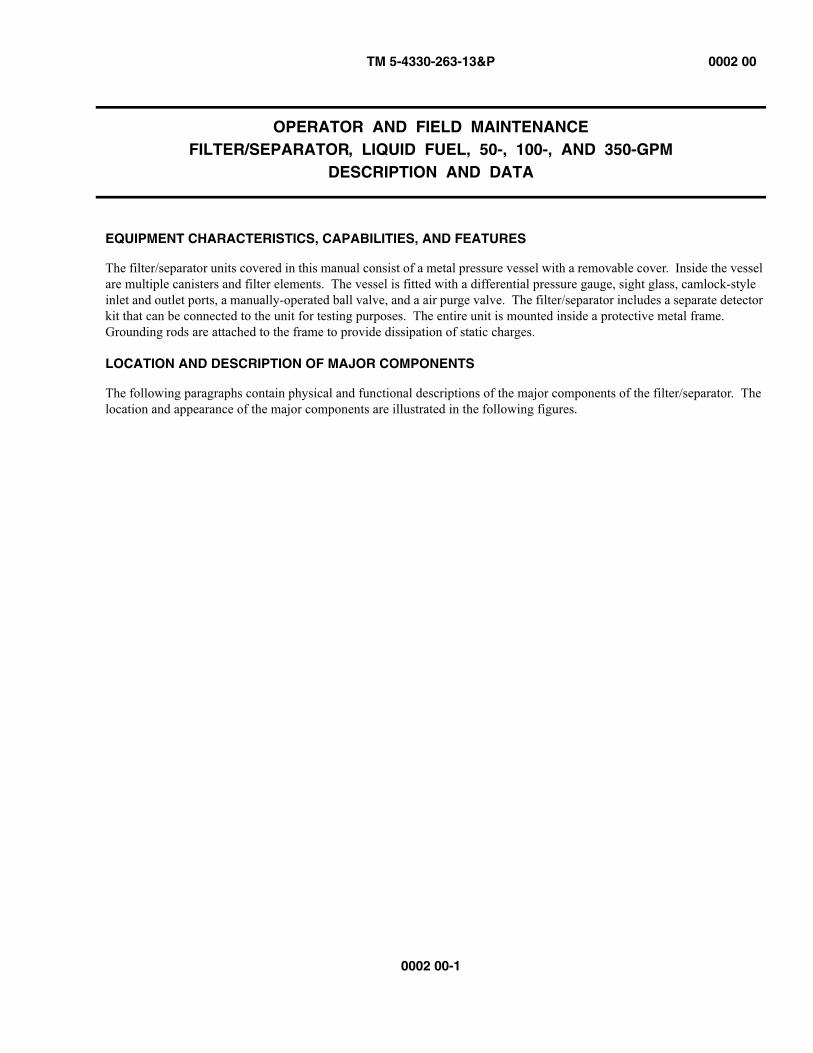
EQUIPMENT CHARACTERISTICS, CAPABILITIES, AND FEATURES
The filter/separator units covered in this manual consist of a metal pressure vessel with a removable cover. Inside the vesselare multiple canisters and filter elements. The vessel is fitted with a differential pressure gauge, sight glass, camlock-styleinlet and outlet ports, a manually-operated ball valve, and a air purge valve. The filter/separator includes a separate detectorkit that can be connected to the unit for testing purposes. The entire unit is mounted inside a protective metal frame. Grounding rods are attached to the frame to provide dissipation of static charges.
LOCATION AND DESCRIPTION OF MAJOR COMPONENTS
The following paragraphs contain physical and functional descriptions of the major components of the filter/separator. The location and appearance of the major components are illustrated in the following figures.
TM 5-4330-263-13&P 0002 00
0002 00-2
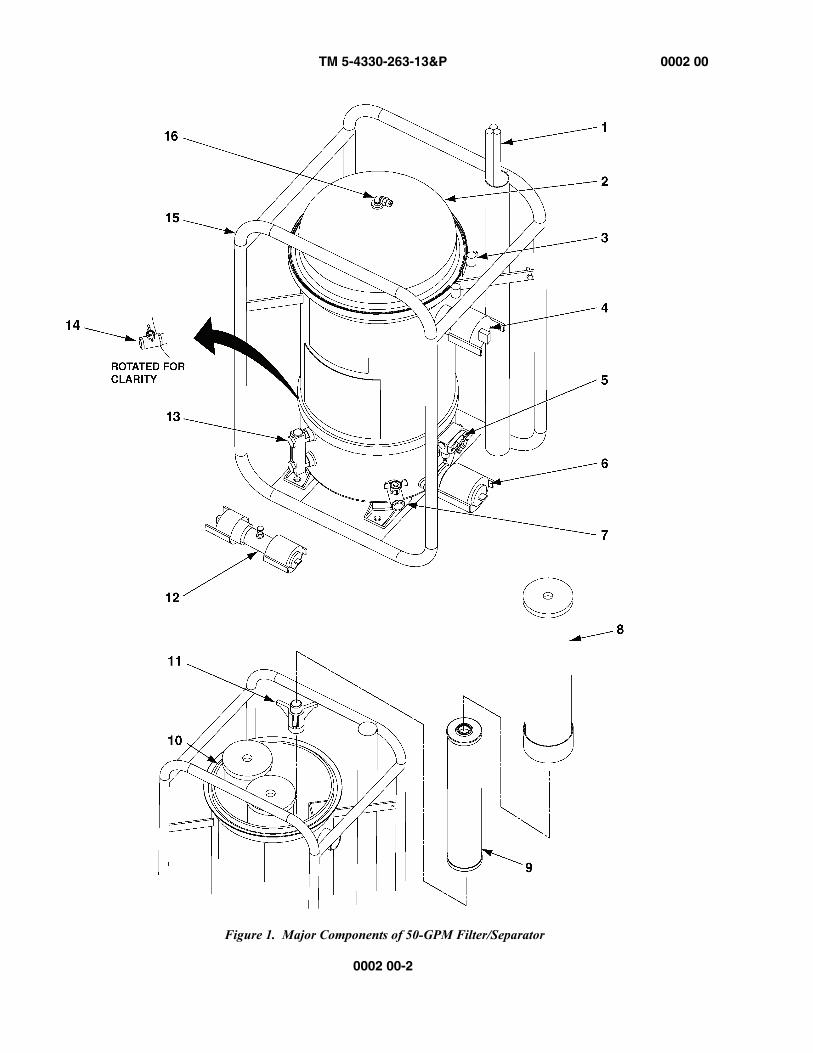
Figure 1. Major Components of 50-GPM Filter/Separator

TM 5-4330-263-13&P 0002 00
0002 00-3
Table 1. 50-GPM Filter/Separator Major Components
No. Item Description
1 Ground Rod The grounding rod is driven into the ground and connected to the frame using a cop-per cable. The grounding rod allows for the dissipation of static electricity that would otherwise build up in the unit as fuel flows through the vessel.
2 Head Assembly The head assembly is a removable cover secured to the top of the vessel by a stain-less steel retaining band. The head assembly is removed to allow access to the coa-lescer elements inside the vessel.
3 Retaining Band The retaining band is a stainless steel belt that is used to secure the head assembly to the top of the vessel A bolt mechanism is used to tighten the retaining band in place.
4 Outlet Coupling Filtered fuel exits the vessel through the outlet coupling at the top of the vessel. The outlet coupling is a standard camlock-type connection for fuel hoses.
5 Differential Pressure Gauge
The differential pressure gauge displays the pressure difference across the filter/sep-arator elements. When filter elements become contaminated, the flow through the elements is impeded, causing an increase in pressure. The Operator monitors the dif-ferential pressure gauge and changes the elements when the pressure difference exceeds a threshold value.
6 Inlet Coupling Fuel to be filtered enters the vessel through the inlet coupling located at the bottom of the vessel. The inlet coupling is a standard camlock-type connection for fuel hoses.
7 Water Drain Valve A lever-operated ball valve used by the Operator to evacuate water from the sump.
8 Canister The canister separates the coalesced water from the fuel.
9 Coalescer The coalescer is the primary filtering component of the filter separator. The coa-lescer coalesces suspended water and removes particulate matter from the fuel before it exits the Filter/Separator through the outlet.
10 O-ring The o-ring provides a seal between the head assembly and the vessel.
11 Bayonet Mount The bayonet provides a mounting surface for the canisters containing the coalescer elements.
12 Detector Kit The detector kit consists of a short pipe nipple with camlock fittings on either end that allow it to be installed in the outlet flow of the filter/separator unit. The nipple is equipped with a probe that allows for sampling of the fuel exiting the filter/separator for testing purposes.
13 Sight Gauge The sight gauge indicates to the operator the level of water collected in the sump.
14 Fuel Drain Valve A lever-operated ball valve used by the Operator to evacuate fuel from the vessel.
15 Frame and Vessel The vessel and frame are a single, welded assembly. The vessel contains the coa-lescer elements of the filter/separator assembly. The frame protects the vessel and attached components from damage and provides a stable, level mounting platform for the vessel.
16 Purge Valve The purge valve is located on top of the vessel’s cover assembly. The Operator acti-vates the purge valve to allow air trapped inside the vessel to escape with minimal fuel loss.

TM 5-4330-263-13&P 0002 00
0002 00-4
Figure 2. Major Components of 100-GPM Filter/Separator
TM 5-4330-263-13&P 0002 00
0002 00-5
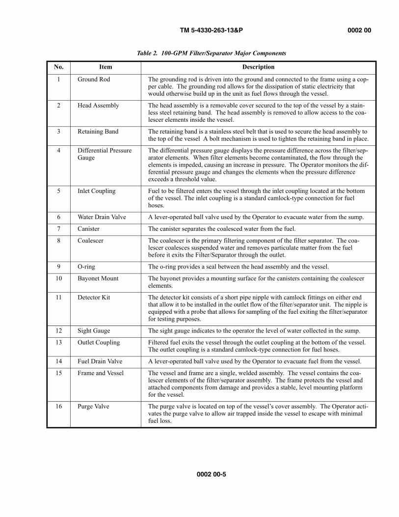
Table 2. 100-GPM Filter/Separator Major Components
No. Item Description
1 Ground Rod The grounding rod is driven into the ground and connected to the frame using a cop-per cable. The grounding rod allows for the dissipation of static electricity that would otherwise build up in the unit as fuel flows through the vessel.
2 Head Assembly The head assembly is a removable cover secured to the top of the vessel by a stain-less steel retaining band. The head assembly is removed to allow access to the coa-lescer elements inside the vessel.
3 Retaining Band The retaining band is a stainless steel belt that is used to secure the head assembly to the top of the vessel A bolt mechanism is used to tighten the retaining band in place.
4 Differential Pressure Gauge
The differential pressure gauge displays the pressure difference across the filter/sep-arator elements. When filter elements become contaminated, the flow through the elements is impeded, causing an increase in pressure. The Operator monitors the dif-ferential pressure gauge and changes the elements when the pressure difference exceeds a threshold value.
5 Inlet Coupling Fuel to be filtered enters the vessel through the inlet coupling located at the bottom of the vessel. The inlet coupling is a standard camlock-type connection for fuel hoses.
6 Water Drain Valve A lever-operated ball valve used by the Operator to evacuate water from the sump.
7 Canister The canister separates the coalesced water from the fuel.
8 Coalescer The coalescer is the primary filtering component of the filter separator. The coa-lescer coalesces suspended water and removes particulate matter from the fuel before it exits the Filter/Separator through the outlet.
9 O-ring The o-ring provides a seal between the head assembly and the vessel.
10 Bayonet Mount The bayonet provides a mounting surface for the canisters containing the coalescer elements.
11 Detector Kit The detector kit consists of a short pipe nipple with camlock fittings on either end that allow it to be installed in the outlet flow of the filter/separator unit. The nipple is equipped with a probe that allows for sampling of the fuel exiting the filter/separator for testing purposes.
12 Sight Gauge The sight gauge indicates to the operator the level of water collected in the sump.
13 Outlet Coupling Filtered fuel exits the vessel through the outlet coupling at the bottom of the vessel. The outlet coupling is a standard camlock-type connection for fuel hoses.
14 Fuel Drain Valve A lever-operated ball valve used by the Operator to evacuate fuel from the vessel.
15 Frame and Vessel The vessel and frame are a single, welded assembly. The vessel contains the coa-lescer elements of the filter/separator assembly. The frame protects the vessel and attached components from damage and provides a stable, level mounting platform for the vessel.
16 Purge Valve The purge valve is located on top of the vessel’s cover assembly. The Operator acti-vates the purge valve to allow air trapped inside the vessel to escape with minimal fuel loss.
TM 5-4330-263-13&P 0002 00
0002 00-6
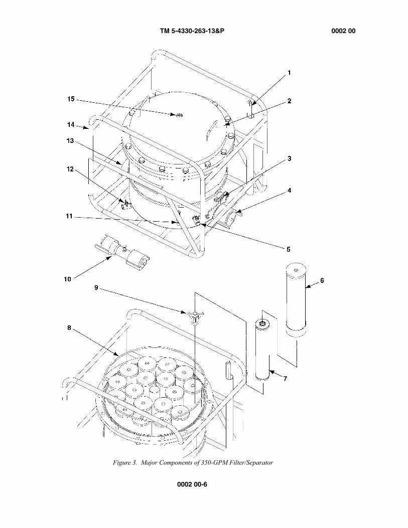
Figure 3. Major Components of 350-GPM Filter/Separator

TM 5-4330-263-13&P 0002 00
0002 00-7
Table 3. 350-GPM Filter/Separator Major Components
No. Item Description
1 Grounding Rod The grounding rod is driven into the ground and connected to the frame using a cop-per cable. The grounding rod allows for the dissipation of static electricity that would otherwise build up in the unit as fuel flows through the vessel.
2 Head Assembly The head assembly is a removable cover secured to the top of the vessel by lid bolts. The head assembly is removed to allow access to the coalescer elements inside the vessel.
3 Differential Pressure Gauge
The differential pressure gauge displays the pressure difference across the filter/sep-arator elements. When filter elements become contaminated, the flow through the elements is impeded, causing an increase in pressure. The Operator monitors the dif-ferential pressure gauge and changes the elements when the pressure difference exceeds a threshold value.
4 Outlet Coupling Filtered fuel exits the vessel through the outlet coupling at the top of the vessel. The outlet coupling is a standard camlock-type connection for fuel hoses.
5 Fuel Drain Valve A lever-operated ball valves that can be opened by the Operator to evacuate fuel from the vessel.
6 Canister The canister separates the coalesced water from the fuel.
7 Coalescer The coalescer is the primary filtering component of the filter separator. The coa-lescer coalesces suspended water and removes particulate matter from the fuel before it exits the Filter/Separator through the outlet.
8 O-ring The o-ring provides a seal between the head assembly and the vessel.
9 Bayonet Mount The bayonet provides a mounting surface for the canisters containing the coalescer elements.
10 Detector Kit The detector kit consists of a short pipe nipple with camlock fittings on either end that allow it to be installed in the outlet flow of the filter/separator unit. The nipple is equipped with a probe that allows for sampling of the fuel exiting the filter/separator for testing purposes.
11 Sight Gauge The sight gauge indicates to the operator the level of water collected in the sump.
12 Water Drain Valve A lever-operated ball valves that can be opened by the Operator to evacuate water from the sump.
13 Inlet Coupling Fuel to be filtered enters the vessel through the inlet coupling located at the bottom of the vessel. The inlet coupling is a standard camlock-type connection for fuel hoses.
14 Frame and Vessel The vessel and frame are a single, welded assembly. The vessel contains the coa-lescer elements of the filter/separator assembly. The frame protects the vessel and attached components from damage and provides a stable, level mounting platform for the vessel.
15 Purge Valve The purge valve is located on top of the vessel’s cover assembly. The operator acti-vates the purge valve to allow air trapped inside the vessel to escape with minimal fuel loss.
TM 5-4330-263-13&P 0002 00
0002 00-8
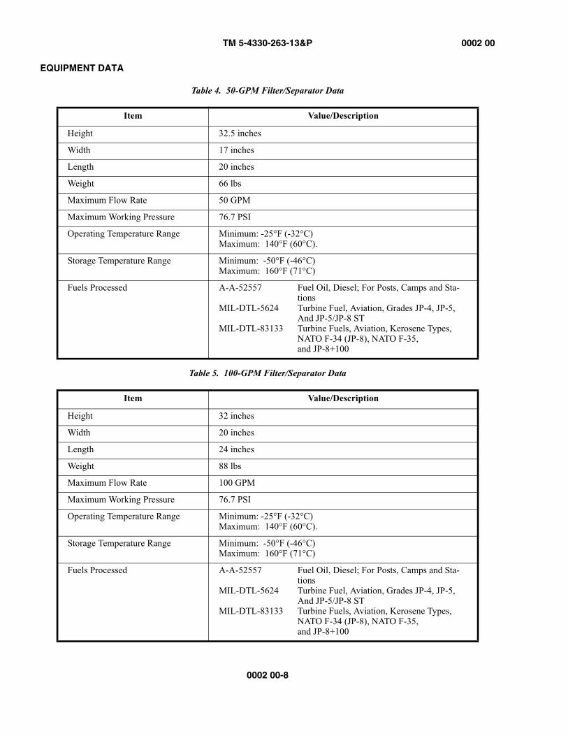
EQUIPMENT DATA
Table 4. 50-GPM Filter/Separator Data
Item Value/Description
Height 32.5 inches
Width 17 inches
Length 20 inches
Weight 66 lbs
Maximum Flow Rate 50 GPM
Maximum Working Pressure 76.7 PSI
Operating Temperature Range Minimum: -25°F (-32°C)Maximum: 140°F (60°C).
Storage Temperature Range Minimum: -50°F (-46°C)Maximum: 160°F (71°C)
Fuels Processed A-A-52557 Fuel Oil, Diesel; For Posts, Camps and Sta-tions
MIL-DTL-5624 Turbine Fuel, Aviation, Grades JP-4, JP-5, And JP-5/JP-8 ST
MIL-DTL-83133 Turbine Fuels, Aviation, Kerosene Types, NATO F-34 (JP-8), NATO F-35, and JP-8+100
Table 5. 100-GPM Filter/Separator Data
Item Value/Description
Height 32 inches
Width 20 inches
Length 24 inches
Weight 88 lbs
Maximum Flow Rate 100 GPM
Maximum Working Pressure 76.7 PSI
Operating Temperature Range Minimum: -25°F (-32°C)Maximum: 140°F (60°C).
Storage Temperature Range Minimum: -50°F (-46°C)Maximum: 160°F (71°C)
Fuels Processed A-A-52557 Fuel Oil, Diesel; For Posts, Camps and Sta-tions
MIL-DTL-5624 Turbine Fuel, Aviation, Grades JP-4, JP-5, And JP-5/JP-8 ST
MIL-DTL-83133 Turbine Fuels, Aviation, Kerosene Types, NATO F-34 (JP-8), NATO F-35, and JP-8+100
TM 5-4330-263-13&P 0002 00
0002 00-9/(0002 00-10 blank)
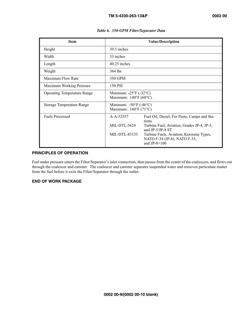
PRINCIPLES OF OPERATION
Fuel under pressure enters the Filter/Separator’s inlet connection, then passes from the center of the coalescers, and flows outthrough the coalescer and canister. The coalescer and canister separates suspended water and removes particulate matter from the fuel before it exits the Filter/Separator through the outlet.
END OF WORK PACKAGE
0002 00
Table 6. 350-GPM Filter/Separator Data
Item Value/Description
Height 39.5 inches
Width 33 inches
Length 40.25 inches
Weight 364 lbs
Maximum Flow Rate 350 GPM
Maximum Working Pressure 150 PSI
Operating Temperature Range Minimum: -25°F (-32°C)Maximum: 140°F (60°C).
Storage Temperature Range Minimum: -50°F (-46°C)Maximum: 160°F (71°C)
Fuels Processed A-A-52557 Fuel Oil, Diesel; For Posts, Camps and Sta-tions
MIL-DTL-5624 Turbine Fuel, Aviation, Grades JP-4, JP-5, and JP-5/JP-8 ST
MIL-DTL-83133 Turbine Fuels, Aviation, Kerosene Types, NATO F-34 (JP-8), NATO F-35, and JP-8+100


TM 5-4330-263-13&P 0003 00
0003 00-1
OPERATOR AND FIELD MAINTENANCEFILTER/SEPARATOR, LIQUID FUEL, 50-, 100-, AND 350-GPM
CONTROLS AND INDICATORS
CONTROLS AND INDICATORS
The operating controls and indicators are illustrated in figure 1, and their names and functions are listed in table 1. The num-bers in the ITEM column of the table correspond to the index numbers on the illustration.
NOTEThe controls and indicators are identical for all filter/separator units. Only the 100-GPM filter/separator unitis shown to illustrate the controls and indicators.

TM 5-4330-263-13&P 0003 00
0003 00-2
Figure 1. Filter/Separator Controls and Indicators
TM 5-4330-263-13&P 0003 00
0003 00-3/(0003 00-4 blank)
END OF WORK PACKAGE
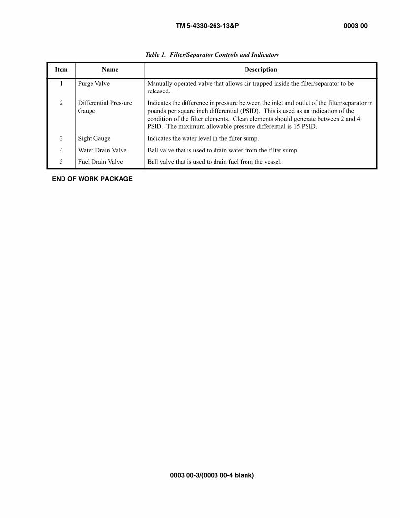
Table 1. Filter/Separator Controls and Indicators
Item Name Description
1 Purge Valve Manually operated valve that allows air trapped inside the filter/separator to be released.
2 Differential Pressure Gauge
Indicates the difference in pressure between the inlet and outlet of the filter/separator in pounds per square inch differential (PSID). This is used as an indication of the condition of the filter elements. Clean elements should generate between 2 and 4 PSID. The maximum allowable pressure differential is 15 PSID.
3 Sight Gauge Indicates the water level in the filter sump.
4 Water Drain Valve Ball valve that is used to drain water from the filter sump.
5 Fuel Drain Valve Ball valve that is used to drain fuel from the vessel.

TM 5-4330-263-13&P 0004 00
0004 00-1
OPERATOR AND FIELD MAINTENANCEFILTER/SEPARATOR, LIQUID FUEL, 50-, 100-, AND 350-GPM
OPERATOR PREVENTIVE MAINTENANCE CHECKS AND SERVICES
INTRODUCTION
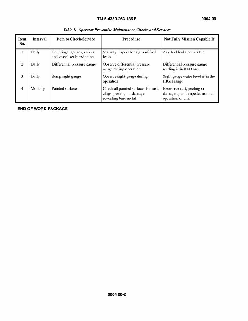
A PMCS table, Table 1, has been provided so you can keep your equipment in good operating condition and ready for its pri-mary mission. Always observe WARNINGS and CAUTIONS appearing in the PMCS table. WARNINGS and CAUTIONS appear before the procedure to which they apply. WARNINGS and CAUTIONS must be observed to avoid serious injury to yourself and others and to prevent damage to the equipment.
The following paragraphs describe the columns of the PMCS table:
1. Item No. Numbers in this column are for reference. When completing DA Form 2404 (Equipment Inspection and Maintenance Worksheet), include the item number for the check/service indicating a fault. Item numbers appear in the order of completion for the intervals listed.
2. Interval. This column tells you when the corresponding procedure must be performed. BEFORE procedures must be done before you operate or use the equipment for its intended mission. DURING procedures must be done during the time you are operating or using the equipment for its intended mission. AFTER procedures must be done immedi-ately after you have operated or used the equipment.
3. Item to Check/Service. This column lists the name of the item to be checked or serviced.
4. Procedure. This column gives the procedure to follow to perform the required check or service and determine if the equipment is ready or available for its intended mission or for operation. You must do this procedure at the time stated in the interval column.
5. Not Fully Mission Capable If. Information in this column tells you what faults will keep your equipment from being capable of performing its primary mission. If the check and service procedures show faults listed in this column, do not operate the equipment. Follow standard operating procedures for maintaining the equipment or reporting equip-ment failure.
TM 5-4330-263-13&P 0004 00
0004 00-2
END OF WORK PACKAGE
Table 1. Operator Preventive Maintenance Checks and Services
ItemNo.
Interval Item to Check/Service Procedure Not Fully Mission Capable If:
1 Daily Couplings, gauges, valves, and vessel seals and joints
Visually inspect for signs of fuel leaks
Any fuel leaks are visible
2 Daily Differential pressure gauge Observe differential pressure gauge during operation
Differential pressure gauge reading is in RED area
3 Daily Sump sight gauge Observe sight gauge during operation
Sight gauge water level is in the HIGH range
4 Monthly Painted surfaces Check all painted surfaces for rust, chips, peeling, or damage revealing bare metal
Excessive rust, peeling or damaged paint impedes normal operation of unit
TM 5-4330-263-13&P 0005 00
0005 00-1/(0005 00-2 blank)
OPERATOR AND FIELD MAINTENANCEFILTER/SEPARATOR, LIQUID FUEL, 50-, 100-, AND 350-GPM
PREPARATION FOR OPERATION
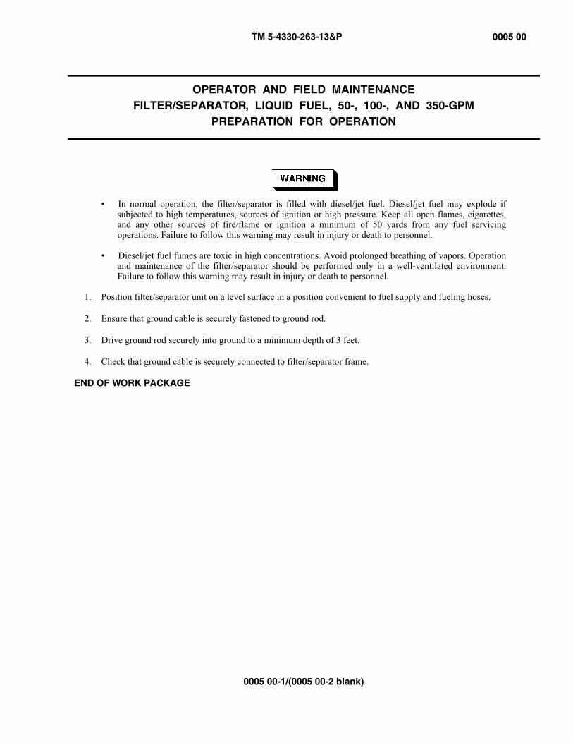
• In normal operation, the filter/separator is filled with diesel/jet fuel. Diesel/jet fuel may explode ifsubjected to high temperatures, sources of ignition or high pressure. Keep all open flames, cigarettes,and any other sources of fire/flame or ignition a minimum of 50 yards from any fuel servicingoperations. Failure to follow this warning may result in injury or death to personnel.
• Diesel/jet fuel fumes are toxic in high concentrations. Avoid prolonged breathing of vapors. Operationand maintenance of the filter/separator should be performed only in a well-ventilated environment.Failure to follow this warning may result in injury or death to personnel.
1. Position filter/separator unit on a level surface in a position convenient to fuel supply and fueling hoses.
2. Ensure that ground cable is securely fastened to ground rod.
3. Drive ground rod securely into ground to a minimum depth of 3 feet.
4. Check that ground cable is securely connected to filter/separator frame.
END OF WORK PACKAGE

TM 5-4330-263-13&P 0006 00
0006 00-1
OPERATOR AND FIELD MAINTENANCEFILTER/SEPARATOR, LIQUID FUEL, 50-, 100-, AND 350-GPM
OPERATION
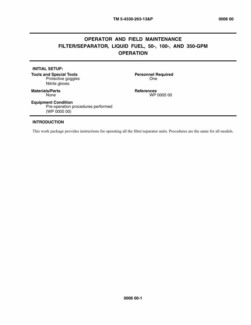
INITIAL SETUP:
INTRODUCTION
This work package provides instructions for operating all the filter/separator units. Procedures are the same for all models.
Tools and Special ToolsProtective gogglesNitrile gloves
Personnel RequiredOne
Materials/PartsNone
ReferencesWP 0005 00
Equipment ConditionPre-operation procedures performed(WP 0005 00)

TM 5-4330-263-13&P 0006 00
0006 00-2
OPERATION UNDER USUAL CONDITIONS
Figure 1. Filter/Separator Unit Operation
• In normal operation, the filter/separator is filled with diesel/jet fuel. Diesel/jet fuel may explode ifsubjected to high temperatures, sources of ignition or high pressure. Keep all open flames, cigarettes,and any other sources of fire/flame or ignition a minimum of 50 yards from any fuel servicingoperations. Failure to follow this warning may result in injury or death to personnel.
• Diesel/jet fuel fumes are toxic in high concentrations. Avoid prolonged breathing of vapors. Operationand maintenance of the filter/separator should be performed only in a well-ventilated environment.Failure to follow this warning may result in injury or death to personnel.
• Diesel/jet fuel is toxic and can severely affect skin, eyes and the respiratory tract. Personnel must wearappropriate hand and eye protection (nitrile gloves and goggles). Wash skin thoroughly with soap andwater if exposed. In case of contact with diesel/jet fuel, flush eyes with clear water for at lest 15minutes . Failure to follow this warning may result in injury or death to personnel.
NOTEThe detector kit can be placed in inlet or outlet side of vessel.
1. If fuel sampling will be conducted, install detector kit (figure 1, 3) on filter/separator inlet or outlet connection (5 or 8) and close camlocks completely.
2. With the pump turned off and no fuel flowing, attach supply hose to inlet connection (5) and close camlocks com-pletely.
3. Attach fueling hose to outlet connection (8) and close camlocks completely.
TM 5-4330-263-13&P 0006 00
0006 00-3
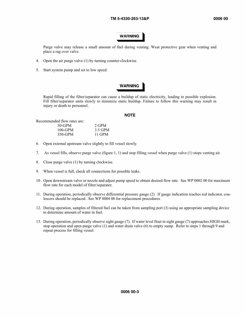
Purge valve may release a small amount of fuel during venting. Wear protective gear when venting andplace a rag over valve.
4. Open the air purge valve (1) by turning counter-clockwise.
5. Start system pump and set to low speed.
Rapid filling of the filter/separator can cause a buildup of static electricity, leading to possible explosion.Fill filter/separator units slowly to minimize static buildup. Failure to follow this warning may result ininjury or death to personnel.
NOTERecommended flow rates are:
50-GPM 2 GPM100-GPM 3.5 GPM350-GPM 11 GPM
6. Open external upstream valve slightly to fill vessel slowly.
7. As vessel fills, observe purge valve (figure 1, 1) and stop filling vessel when purge valve (1) stops venting air.
8. Close purge valve (1) by turning clockwise.
9. When vessel is full, check all connections for possible leaks.
10. Open downstream valve or nozzle and adjust pump speed to obtain desired flow rate. See WP 0002 00 for maximum flow rate for each model of filter/separator.
11. During operation, periodically observe differential pressure gauge (2). If gauge indication reaches red indicator, coa-lescers should be replaced. See WP 0004 00 for replacement procedures.
12. During operation, samples of filtered fuel can be taken from sampling port (3) using an appropriate sampling device to determine amount of water in fuel.
13. During operation, periodically observe sight gauge (7). If water level float in sight gauge (7) approaches HIGH mark, stop operation and open purge valve (1) and water drain valve (6) to empty sump. Refer to steps 1 through 9 and repeat process for filling vessel.

TM 5-4330-263-13&P 0006 00
0006 00-4
Rapid closure of downstream valves or nozzles during fueling with a high-pressure pump can result inoverpressurization of vessel and cause fuel leaks, leading to possible explosion. Failure to follow thiswarning may result in injury or death to personnel.
NOTEWater should be drained from the sump daily, or after each fueling operation. See “Post-OperationProcedures” on page 0006 00-4 for more information.
Figure 2. Filter/Separator Unit Post-Operation
POST-OPERATION PROCEDURES
1. When fueling operations are complete, shut down pumping system and close upstream and downstream valves to iso-late filter/separator.
2. Open purge valve (figure 2, 1) by turning counter-clockwise.
3. Place a suitable container under water drain valve (2) and open water drain valve (2) to drain any water that has accu-mulated in sump.
4. When all water has drained and green ball in sight gauge (3) reaches bottom, fuel will begin to flow from valve. Close water drain valve (2).
5. Dispose of contaminated liquids in accordance with federal and local regulations.
TM 5-4330-263-13&P 0006 00
0006 00-5/(0006 00-6 blank)
NOTEIf filter/separator vessel is to remain installed in fueling system, open upstream valve and refer to “Operation UnderUsual Conditions” on page 0006 00-2 to fill vessel with fuel.
6. If filter/separator vessel is to be removed and relocated, obtain a suitable container and place it below fuel drain valve (4).
Diesel/jet fuel is toxic to skin, eyes and respiratory tract. Personnel must wear appropriate hand and eyeprotection (nitrile gloves and goggles). Wash skin thoroughly with soap and water if exposed. Flush eyeswith clear water for at least 15 minutes in case of contact with diesel/jet fuel.
7. Open fuel drain valve (4) and drain contents of vessel.
8. When all fuel has drained, close fuel drain valve (4) and purge valve (1) and disconnect hoses from inlet and outlet couplings.
9. If installed, disconnect and stow detector kit.
10. Drain residual fuel from hoses.
11. Dispose of excess fuel in accordance with federal and local regulations.
END OF WORK PACKAGE


TM 5-4330-263-13&P 0007 00
0007 00-1/(0007 00-2 blank)
OPERATOR AND FIELD MAINTENANCEFILTER/SEPARATOR, LIQUID FUEL, 50- 100-, AND 350-GPM
FIELD PREVENTIVE MAINTENANCE CHECKS AND SERVICES (PMCS)
INTRODUCTION
A PMCS table, Table 1, has been provided so you can keep your equipment in good operating condition and ready for its pri-mary mission. Always observe WARNINGS and CAUTIONS appearing in the PMCS table. WARNINGS and CAUTIONS appear before the procedure to which they apply. WARNINGS and CAUTIONS must be observed to avoid serious injury to yourself and others and to prevent damage to the equipment.
The following paragraphs describe the columns of the PMCS table
1. Item No. Numbers in this column are for reference. When completing DA Form 2404 (Equipment Inspection and Maintenance Worksheet), include the item number for the check/service indicating a fault. Item numbers appear in the order of completion for the intervals listed.
2. Interval. This column tells you when the corresponding procedure must be performed. BEFORE procedures must be done before you operate or use the equipment for its intended mission. DURING procedures must be done during the time you are operating or using the equipment for its intended mission. AFTER procedures must be done immedi-ately after you have operated or used the equipment.
3. Item to Check/Service. This column lists the name of the item to be checked or serviced.
4. Procedure. This column gives the procedure to follow to perform the required check or service and determine if the equipment is ready or available for its intended mission or for operation. You must do this procedure at the time stated in the interval column.
5. Not Fully Mission Capable If. Information in this column tells you what faults will keep your equipment from being capable of performing its primary mission. If the check and service procedures show faults listed in this column, do not operate the equipment. Follow standard operating procedures for maintaining the equipment or reporting equip-ment failure.
END OF WORK PACKAGE
Table 1. Field Maintenance Preventive Maintenance Checks and Services
ITEM NO. INTERVAL
ITEM TOCHECK/SERVICE PROCEDURE
NOT FULLY MISSION CAPABLE IF:
1 Quarterly Retaining Band Bolts (50- and 100-GPM)
Check for tightness and torque as required
Loose or damaged
2 Quarterly Lid Bolts (350-GPM) Check for tightness and torque as required
Loose or damages
3 Quarterly Differential Pressure Gauge Check for damage Gauge is damaged4 Quarterly Sight Gauge Check body for cracks
and ball float for damageGauge is damaged
5 Quarterly Ground Rod Check for missing or damaged sections
Ground rod or connections are missing or damaged
6 Quarterly Frame and Vessel Inspect for damage. Clean and repaint
Tank leaks or frame is damaged such that it does not fully protect vessel and fittings.

TM 5-4330-263-13&P 0008 00
0008 00-1/(0008 00-2 blank)
OPERATOR AND FIELD MAINTENANCEFILTER/SEPARATOR, LIQUID FUEL, 50-, 100-, AND 350-GPM
TROUBLESHOOTING
INTRODUCTION
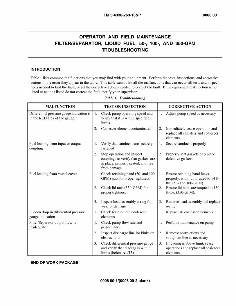
Table 1 lists common malfunctions that you may find with your equipment. Perform the tests, inspections, and corrective actions in the order they appear in the table. This table cannot list all the malfunctions that can occur, all tests and inspec-tions needed to find the fault, or all the corrective actions needed to correct the fault. If the equipment malfunction is notlisted or actions listed do not correct the fault, notify your supervisor.
END OF WORK PACKAGE
Table 1. Troubleshooting
MALFUNCTION TEST OR INSPECTION CORRECTIVE ACTION
Differential pressure gauge indication is in the RED area of the gauge.
1. Check pump operating speed and verify that it is within specified limits
1. Adjust pump speed as necessary
2. Coalescer element contaminated 2. Immediately cease operation and replace all canisters and coalescer elements
Fuel leaking from input or output coupling
1. Verify that camlocks are securely fastened
1. Secure camlocks properly
2. Stop operation and inspect couplings to verify that gaskets are in place, properly seated, and free from damage
2. Properly seat gaskets or replace defective gaskets
Fuel leaking from vessel cover 1. Check retaining band (50- and 100-GPM) nuts for proper tightness.
2. Check lid nuts (350-GPM) for proper tightness
3. Inspect head assembly o-ring for wear or damage
1. Ensure retaining band locks properly, with nut torqued to 14 ft-lbs. (50- and 100-GPM).
2. Ensure lid bolts are torqued to 150 ft-lbs. (350-GPM).
3. Remove head assembly and replace o-ring
Sudden drop in differential pressure gauge indication
1. Check for ruptured coalescer elements
1. Replace all coalescer elements
Filter/Separator output flow is inadequate
1. Check pump flow rate and performance
1. Perform maintenance on pump
2. Inspect discharge line for kinks or obstructions
2. Remove obstructions and straighten line as necessary
3. Check differential pressure gauge and verify that reading is within limits (below red/15)
3. If reading is above limit, cease operations and replace all coalescer elements.

TM 5-4330-263-13&P 0009 00
0009 00-1
OPERATOR AND FIELD MAINTENANCEFILTER/SEPARATOR, LIQUID FUEL, 50-, 100-, 350-GPM
ELEMENT REPLACEMENT
INITIAL SETUP:
INTRODUCTION
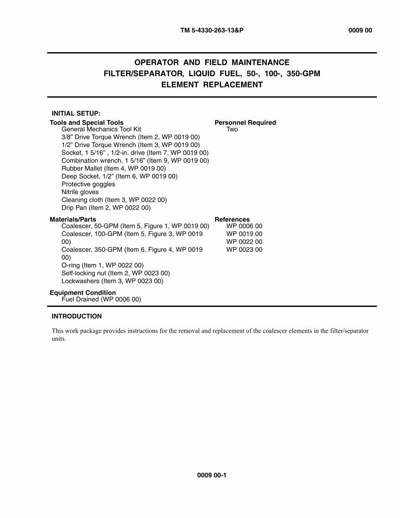
This work package provides instructions for the removal and replacement of the coalescer elements in the filter/separator units.
Tools and Special ToolsGeneral Mechanics Tool Kit3/8” Drive Torque Wrench (Item 2, WP 0019 00)1/2” Drive Torque Wrench (Item 3, WP 0019 00)Socket, 1 5/16” , 1/2-in. drive (Item 7, WP 0019 00)Combination wrench, 1 5/16” (Item 9, WP 0019 00)Rubber Mallet (Item 4, WP 0019 00)Deep Socket, 1/2” (Item 6, WP 0019 00)Protective gogglesNitrile glovesCleaning cloth (Item 3, WP 0022 00)Drip Pan (Item 2, WP 0022 00)
Personnel RequiredTwo
Materials/PartsCoalescer, 50-GPM (Item 5, Figure 1, WP 0019 00)Coalescer, 100-GPM (Item 5, Figure 3, WP 0019 00)Coalescer, 350-GPM (Item 6, Figure 4, WP 0019 00)O-ring (Item 1, WP 0022 00)Self-locking nut (Item 2, WP 0023 00)Lockwashers (Item 3, WP 0023 00)
ReferencesWP 0006 00WP 0019 00WP 0022 00WP 0023 00
Equipment ConditionFuel Drained (WP 0006 00)

TM 5-4330-263-13&P 0009 00
0009 00-2
Figure 1. 50- and 100-GPM Unit Element Replacement
50- AND 100-GPM UNIT ELEMENT REMOVAL
• In normal operation, the filter/separator is filled with diesel/jet fuel. Diesel/jet fuel may explode ifsubjected to high temperatures, sources of ignition or high pressure, resulting in bodily injury or deathto personnel. Keep all open flames, cigarettes, and any other sources of fire/flame or ignition aminimum of 50 yards from any fuel servicing operations.
• Diesel/jet fuel is toxic to skin, eyes and respiratory tract. Personnel must wear appropriate hand andeye protection (nitrile gloves and goggles). Wash skin thoroughly with soap and water if exposed.Flush eyes with clear water for at lest 15 minutes in case of contact with diesel/jet fuel.
• Diesel/jet fuel fumes are toxic in high concentrations. Avoid prolonged breathing of vapors. Operationand maintenance of the filter/separator should be performed only in a well-ventilated environment.Failure to follow this warning may result in injury or death to personnel.
CAUTION
Inside surfaces of vessel cover should not be touched in order to minimize the possibility of contaminationof the filter/separator unit. Do not place the vessel cover on the bare ground or in grass to avoid possiblecontamination.
1. Unscrew self-locking nut (figure 1, 4) on retaining band (3) and remove retaining band (3) and head assembly (1). Discard self-locking nut (4).
2. Remove o-ring (2) from vessel (7).
3. Press canister (5) down and turn counter-clockwise approximately 120 degrees to disengage locking mechanism.
TM 5-4330-263-13&P 0009 00
0009 00-3
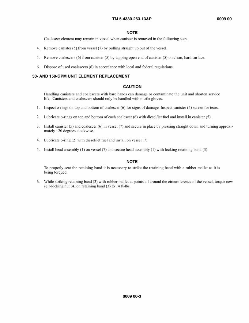
NOTECoalescer element may remain in vessel when canister is removed in the following step.
4. Remove canister (5) from vessel (7) by pulling straight up out of the vessel.
5. Remove coalescers (6) from canister (5) by tapping open end of canister (5) on clean, hard surface.
6. Dispose of used coalescers (6) in accordance with local and federal regulations.
50- AND 150-GPM UNIT ELEMENT REPLACEMENT
CAUTION
Handling canisters and coalescers with bare hands can damage or contaminate the unit and shorten servicelife. Canisters and coalescers should only be handled with nitrile gloves.
1. Inspect o-rings on top and bottom of coalescer (6) for signs of damage. Inspect canister (5) screen for tears.
2. Lubricate o-rings on top and bottom of each coalescer (6) with diesel/jet fuel and install in canister (5).
3. Install canister (5) and coalescer (6) in vessel (7) and secure in place by pressing straight down and turning approxi-mately 120 degrees clockwise.
4. Lubricate o-ring (2) with diesel/jet fuel and install on vessel (7).
5. Install head assembly (1) on vessel (7) and secure head assembly (1) with locking retaining band (3).
NOTETo properly seat the retaining band it is necessary to strike the retaining band with a rubber mallet as it isbeing torqued.
6. While striking retaining band (3) with rubber mallet at points all around the circumference of the vessel, torque new self-locking nut (4) on retaining band (3) to 14 ft-lbs.

TM 5-4330-263-13&P 0009 00
0009 00-4
Figure 2. 350-GPM Unit Element Replacement
350-GPM UNIT ELEMENT REMOVAL
• Diesel/jet fuel is toxic to skin, eyes and respiratory tract. Personnel must wear appropriate hand andeye protection (nitrile gloves and goggles). Wash skin thoroughly with soap and water if exposed.Flush eyes with clear water for at lest 15 minutes in case of contact with diesel/jet fuel.
• Diesel/jet fuel fumes are toxic in high concentrations. Avoid prolonged breathing of vapors. Operationand maintenance of the filter/separator should be performed only in a well-ventilated environment.Failure to follow this warning may result in injury or death to personnel.
• Removing head assembly requires a two-man lift to avoid injury to personnel.
CAUTION
Inside surfaces of vessel cover should not be touched in order to minimize the possibility of contaminationof the filter/separator unit. Do not place the vessel cover on the bare ground or in grass to avoid possiblecontamination.
1. Remove 14 lid bolts (10), flat washers (9) and (6), lockwashers (5), and nuts (4) and remove head assembly (1). Discard lockwashers (5).
2. Remove o-ring (8) from vessel (7).
TM 5-4330-263-13&P 0009 00
0009 00-5
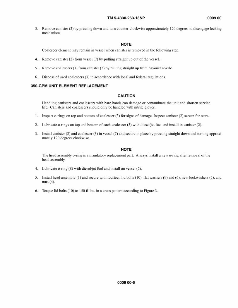
3. Remove canister (2) by pressing down and turn counter-clockwise approximately 120 degrees to disengage locking mechanism.
NOTECoalescer element may remain in vessel when canister is removed in the following step.
4. Remove canister (2) from vessel (7) by pulling straight up out of the vessel.
5. Remove coalescers (3) from canister (2) by pulling straight up from bayonet nozzle.
6. Dispose of used coalescers (3) in accordance with local and federal regulations.
350-GPM UNIT ELEMENT REPLACEMENT
CAUTION
Handling canisters and coalescers with bare hands can damage or contaminate the unit and shorten servicelife. Canisters and coalescers should only be handled with nitrile gloves.
1. Inspect o-rings on top and bottom of coalescer (3) for signs of damage. Inspect canister (2) screen for tears.
2. Lubricate o-rings on top and bottom of each coalescer (3) with diesel/jet fuel and install in canister (2).
3. Install canister (2) and coalescer (3) in vessel (7) and secure in place by pressing straight down and turning approxi-mately 120 degrees clockwise.
NOTEThe head assembly o-ring is a mandatory replacement part. Always install a new o-ring after removal of thehead assembly.
4. Lubricate o-ring (8) with diesel/jet fuel and install on vessel (7).
5. Install head assembly (1) and secure with fourteen lid bolts (10), flat washers (9) and (6), new lockwashers (5), and nuts (4).
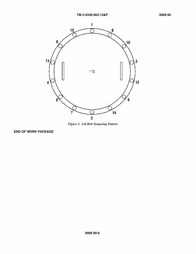
6. Torque lid bolts (10) to 150 ft-lbs. in a cross pattern according to Figure 3.
TM 5-4330-263-13&P 0009 00
0009 00-6
Figure 3. Lid Bolt Torqueing Pattern
END OF WORK PACKAGE
TM 5-4330-263-13&P 0010 00
0010 00-1
OPERATOR AND FIELD MAINTENANCEFILTER/SEPARATOR, LIQUID FUEL, 50-, 100-, AND 350-GPM
SIGHT GAUGE REPLACEMENT
INITIAL SETUP:
INTRODUCTION
This work package provides instructions for replacing the sight gauge. The procedure is the same for all three models of the filter separator.
REMOVAL
• In normal operation, the filter/separator is filled with diesel/jet fuel. Diesel/jet fuel may explode ifsubjected to high temperatures, sources of ignition or high pressure, resulting in bodily injury or deathto personnel. Keep all open flames, cigarettes, and any other sources of fire/flame or ignition aminimum of 50 yards from any fuel servicing operations.
• Diesel/jet fuel is toxic to skin, eyes and respiratory tract. Personnel must wear appropriate hand andeye protection (nitrile gloves and goggles). Wash skin thoroughly with soap and water if exposed.Flush eyes with clear water for at lest 15 minutes in case of contact with diesel/jet fuel.
• Diesel/jet fuel fumes are toxic in high concentrations. Avoid prolonged breathing of vapors. Operationand maintenance of the filter/separator should be performed only in a well-ventilated environment.Failure to follow this warning may result in injury or death to personnel.
Tools and Special ToolsGeneral Mechanics Tool KitProtective gogglesNitrile glovesCleaning cloth (Item 3, WP 0022 00)Drip Pan (Item 2, WP 0022 00)
Personnel RequiredOne
Materials/PartsSight gauge, 50-GPM (Item 21, Figure 1, WP0019)Sight gauge, 100-GPM (Item 31, Figure 3, WP0019)Sight gauge, 350-GPM (Item 29, Figure 4, WP0019)Compound, Antiseize (Item 2, WP 0022 00)
ReferencesWP 0006 00WP 0022 00
Equipment ConditionFuel Drained (WP 0006 00)
TM 5-4330-263-13&P 0010 00
0010 00-2
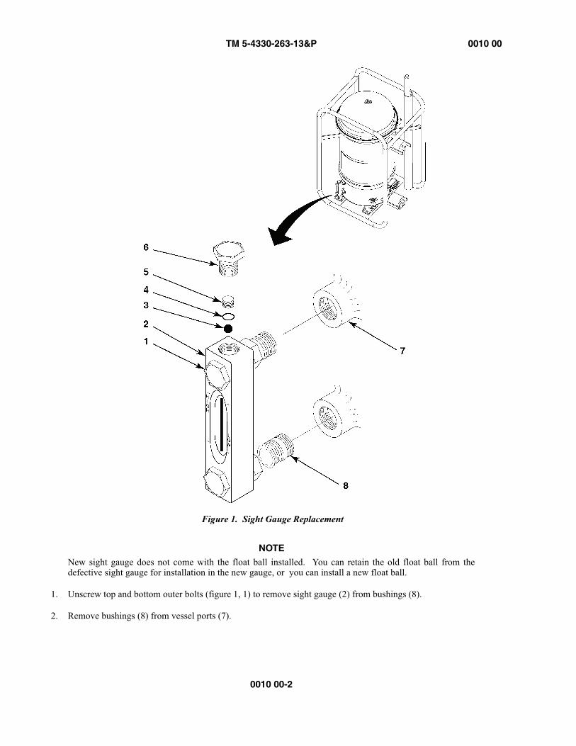
Figure 1. Sight Gauge Replacement
NOTENew sight gauge does not come with the float ball installed. You can retain the old float ball from thedefective sight gauge for installation in the new gauge, or you can install a new float ball.
1. Unscrew top and bottom outer bolts (figure 1, 1) to remove sight gauge (2) from bushings (8).
2. Remove bushings (8) from vessel ports (7).
TM 5-4330-263-13&P 0010 00
0010 00-3/(0010 00-4 blank)
NOTEPerform steps 3 and 4 only if you are retaining the float ball for use in the new gauge. If you are using a newfloat ball, proceed to replacement procedure.
3. Remove top capscrew (6), setscrew (5), and gasket (4) from top of sight gauge (2).
4. Remove float ball (3) from sight gauge (2).
REPLACEMENT
1. Insert float ball (3) in sight gauge (2).
NOTEVerify that glass tube inside sight gauge is properly oriented before installing setscrew. Glass tube should beturned so that the red background is to the rear of the gauge. Ensure that HIGH and LOW markers on sightgauge are properly oriented.
2. Install gasket (4), setscrew (5), and top capscrew (6).
3. Apply antiseize compound to threads of top and bottom bushings (8).
4. Install bushings (8) in vessel ports (7).
5. Install sight gauge (2) on bushings (8) by alternately tightening top and bottom outer bolts (1).
END OF WORK PACKAGE

TM 5-4330-263-13&P 0011 00
0011 00-1
OPERATOR AND FIELD MAINTENANCEFILTER/SEPARATOR, LIQUID FUEL, 50-, 100-, AND 350-GPM
DIFFERENTIAL PRESSURE GAUGE REPLACEMENT
INITIAL SETUP:
INTRODUCTION
This work package provides instructions for replacing the differential pressure gauge. The procedure is the same for all threemodels of the filter separator.
• In normal operation, the filter/separator is filled with diesel/jet fuel. Diesel/jet fuel may explode ifsubjected to high temperatures, sources of ignition or high pressure, resulting in bodily injury or deathto personnel. Keep all open flames, cigarettes, and any other sources of fire/flame or ignition aminimum of 50 yards from any fuel servicing operations.
• Diesel/jet fuel is toxic to skin, eyes and respiratory tract. Personnel must wear appropriate hand andeye protection (nitrile gloves and goggles). Wash skin thoroughly with soap and water if exposed.Flush eyes with clear water for at lest 15 minutes in case of contact with diesel/jet fuel.
• Diesel/jet fuel fumes are toxic in high concentrations. Avoid prolonged breathing of vapors. Operationand maintenance of the filter/separator should be performed only in a well-ventilated environment.Failure to follow this warning may result in injury or death to personnel.
Tools and Special ToolsGeneral Mechanics Tool KitProtective gogglesNitrile glovesCleaning cloth (Item 3, WP 0022 00)Drip Pan (Item 2, WP 0022 00)
Personnel RequiredOne
Materials/PartsSight gauge, 50-GPM (Item 13, Figure 1, WP0019)Sight gauge, 100-GPM (Item 9, Figure 3, WP0019)Sight gauge, 350-GPM (Item 16, Figure 4, WP0019)Compound, Antiseize (Item 2, WP 0022 00)
ReferencesWP 0006 00WP 0022 00
Equipment ConditionFuel Drained (WP 0006 00)
TM 5-4330-263-13&P 0011 00
0011 00-2
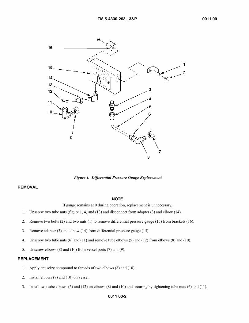
Figure 1. Differential Pressure Gauge Replacement
REMOVAL
NOTEIf gauge remains at 0 during operation, replacement is unnecessary.
1. Unscrew two tube nuts (figure 1, 4) and (13) and disconnect from adapter (3) and elbow (14).
2. Remove two bolts (2) and two nuts (1) to remove differential pressure gauge (15) from brackets (16).
3. Remove adapter (3) and elbow (14) from differential pressure gauge (15).
4. Unscrew two tube nuts (6) and (11) and remove tube elbows (5) and (12) from elbows (8) and (10).
5. Unscrew elbows (8) and (10) from vessel ports (7) and (9).
REPLACEMENT
1. Apply antiseize compound to threads of two elbows (8) and (10).
2. Install elbows (8) and (10) on vessel.
3. Install two tube elbows (5) and (12) on elbows (8) and (10) and securing by tightening tube nuts (6) and (11).
TM 5-4330-263-13&P 0011 00
0011 00-3/0011 00-4 blank
4. Install adapter (3) and elbow (14) on differential pressure gauge (15).
5. Connect adapter (3) and elbow (14) to tube elbows (5) and (12) and tighten tube nuts (4) and (13).
6. Install differential pressure gauge (15) on brackets (16) and secure with two bolts (2) and two nuts (1).
END OF WORK PACKAGE

TM 5-4330-263-13&P 0012 00
0012 00-1
OPERATOR AND FIELD MAINTENANCEFILTER/SEPARATOR, LIQUID FUEL, 50- AND 100-GPM
FUEL AND WATER DRAIN VALVE REPLACEMENT
INITIAL SETUP:
INTRODUCTION
This work package provides instructions for replacing the fuel and water drain valves. The procedure is the same for all three models of the filter separator.
• In normal operation, the filter/separator is filled with diesel/jet fuel. Diesel/jet fuel may explode ifsubjected to high temperatures, sources of ignition or high pressure, resulting in bodily injury or deathto personnel. Keep all open flames, cigarettes, and any other sources of fire/flame or ignition aminimum of 50 yards from any fuel servicing operations.
• Diesel/jet fuel is toxic to skin, eyes and respiratory tract. Personnel must wear appropriate hand andeye protection (nitrile gloves and goggles). Wash skin thoroughly with soap and water if exposed.Flush eyes with clear water for at lest 15 minutes in case of contact with diesel/jet fuel.
• Diesel/jet fuel fumes are toxic in high concentrations. Avoid prolonged breathing of vapors. Operationand maintenance of the filter/separator should be performed only in a well-ventilated environment.Failure to follow this warning may result in injury or death to personnel.
Tools and Special ToolsCombination wrench, 1 1/4” (Item 8, WP 0019 00)Combination wrench, 1” (Item 10, WP 0019 00)Protective gogglesNitrile glovesCleaning cloth (Item 3, WP 0022 00)Drip Pan (Item 2, WP 0022 00)
Personnel RequiredOne
Materials/PartsDrain valve, 50-GPM (Item 27, Figure 1, WP 0019 00)Drain valve, 100-GPM (Item 19, Figure 3, WP 0019 00)Drain valve, 350-GPM (Item 27, Figure 4, WP 0019 00)Compound, Antiseize (Item 2, WP 0022 00)
ReferencesWP 0006 00WP 0019 00WP 0022 00
Equipment ConditionFuel Drained (WP 0006 00)
TM 5-4330-263-13&P 0012 00
0012 00-2
REMOVAL
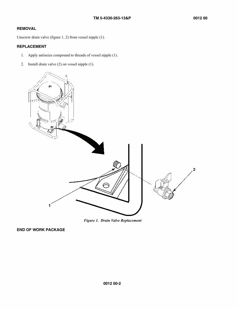
Unscrew drain valve (figure 1, 2) from vessel nipple (1).
REPLACEMENT
1. Apply antiseize compound to threads of vessel nipple (1).
2. Install drain valve (2) on vessel nipple (1).
Figure 1. Drain Valve Replacement
END OF WORK PACKAGE
TM 5-4330-263-13&P 0013 00
0013 00-1
OPERATOR AND UNIT MAINTENANCEFILTER/SEPARATOR, LIQUID FUEL, 50-, 100-, AND 350-GPM
PURGE VALVE REPLACEMENT
INITIAL SETUP:
INTRODUCTION
This work package provides instructions for replacing the fuel and water drain valves. The procedure is the same for all three models of the filter separator.
• In normal operation, the filter/separator is filled with diesel/jet fuel. Diesel/jet fuel may explode ifsubjected to high temperatures, sources of ignition or high pressure, resulting in bodily injury or deathto personnel. Keep all open flames, cigarettes, and any other sources of fire/flame or ignition aminimum of 50 yards from any fuel servicing operations.
• Diesel/jet fuel is toxic to skin, eyes and respiratory tract. Personnel must wear appropriate hand andeye protection (nitrile gloves and goggles). Wash skin thoroughly with soap and water if exposed.Flush eyes with clear water for at lest 15 minutes in case of contact with diesel/jet fuel.
• Diesel/jet fuel fumes are toxic in high concentrations. Avoid prolonged breathing of vapors. Operationand maintenance of the filter/separator should be performed only in a well-ventilated environment.Failure to follow this warning may result in injury or death to personnel.
Tools and Special ToolsGeneral Mechanics Tool KitProtective gogglesNitrile glovesCleaning cloth (Item 3, WP 0022 00)Drip Pan (Item 2, WP 0022 00)
Personnel RequiredOne
Materials/PartsPurge valve, 50-GPM (Item 2, Figure 1, WP 0019 00)Purge valve, 100-GPM (Item 2, Figure 3, WP 0019 00)Purge valve, 350-GPM (Item 2, Figure 4, WP 0019 00)Compound, antiseize (Item 2, WP 0022 00)
ReferencesWP 0006 00WP 0022 00
Equipment ConditionNot applicable
TM 5-4330-263-13&P 0013 00
0013 00-2
REMOVAL
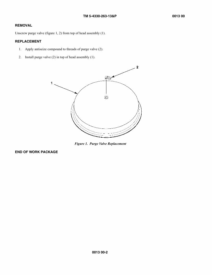
Unscrew purge valve (figure 1, 2) from top of head assembly (1).
REPLACEMENT
1. Apply antiseize compound to threads of purge valve (2).
2. Install purge valve (2) in top of head assembly (1).
Figure 1. Purge Valve Replacement
END OF WORK PACKAGE
TM 5-4330-263-13&P 0014 00
0014 00-1
OPERATOR AND FIELD MAINTENANCEFILTER/SEPARATOR, LIQUID FUEL, 50-, 100-, AND 350-GPM
BAYONET REPLACEMENT
INITIAL SETUP:
INTRODUCTION
This work package provides instructions for replacing the bayonet. The procedure is the same for all three models of the fil-ter separator.
Tools and Special ToolsGeneral Mechanics Tool KitBayonet Socket (Item 1, WP 0019 00) Torque Wrench, 1/2” drive (Item 3, WP 0019 00)Protective gogglesNitrile glovesCleaning cloth (Item 3, WP 0022 00)Drip Pan (Item 2, WP 0022 00)
Personnel RequiredOne
Materials/PartsBayonet, 50-GPM (Item 6, Figure 1, WP 0019 00)Bayonet, 100-GPM (Item 6, Figure 3, WP 0019 00)Bayonet, 350-GPM (Item 7, Figure 4, WP 0019 00)Compound, Antiseize (Item 2, WP 0022 00)
ReferencesWP 0006 00WP 0018 00WP 0022 00
Equipment ConditionCanisters and Coalescer Elements removed(WP 0006 00)

TM 5-4330-263-13&P 0014 00
0014 00-2
• In normal operation, the filter/separator is filled with diesel/jet fuel. Diesel/jet fuel may explode ifsubjected to high temperatures, sources of ignition or high pressure, resulting in bodily injury or deathto personnel. Keep all open flames, cigarettes, and any other sources of fire/flame or ignition aminimum of 50 yards from any fuel servicing operations.
• Diesel/jet fuel is toxic to skin, eyes and respiratory tract. Personnel must wear appropriate hand andeye protection (nitrile gloves and goggles). Wash skin thoroughly with soap and water if exposed.Flush eyes with clear water for at lest 15 minutes in case of contact with diesel/jet fuel.
• Diesel/jet fuel fumes are toxic in high concentrations. Avoid prolonged breathing of vapors. Operationand maintenance of the filter/separator should be performed only in a well-ventilated environment.Failure to follow this warning may result in injury or death to personnel.
Figure 1. Bayonet Replacement
REMOVAL
Using 1/2-inch drive socket wrench, long extension, and bayonet socket, unscrew bayonet (1) from fitting (2).
REPLACEMENT
1. Apply anti-seize pipe antiseize compound to threads of bayonet (1).
2. Install bayonet (1) on fitting (2) and torque to 50 ft-lbs.
END OF WORK PACKAGE
TM 5-4330-263-13&P 0015 00
0015 00-1
OPERATOR AND FIELD MAINTENANCEFILTER/SEPARATOR, LIQUID FUEL, 50-, 100-, AND 350-GPM
CAMLOCK REPLACEMENT
INITIAL SETUP:
INTRODUCTION
This work package provides instructions for replacing the camlocks. The procedure is the same for all three models of the filter separator.
• In normal operation, the filter/separator is filled with diesel/jet fuel. Diesel/jet fuel may explode ifsubjected to high temperatures, sources of ignition or high pressure, resulting in bodily injury or deathto personnel. Keep all open flames, cigarettes, and any other sources of fire/flame or ignition aminimum of 50 yards from any fuel servicing operations.
• Diesel/jet fuel is toxic to skin, eyes and respiratory tract. Personnel must wear appropriate hand andeye protection (nitrile gloves and goggles). Wash skin thoroughly with soap and water if exposed.Flush eyes with clear water for at lest 15 minutes in case of contact with diesel/jet fuel.
• Diesel/jet fuel fumes are toxic in high concentrations. Avoid prolonged breathing of vapors. Operationand maintenance of the filter/separator should be performed only in a well-ventilated environment.Failure to follow this warning may result in injury or death to personnel.
Tools and Special ToolsGeneral Mechanics Tool KitPipe Wrench (Item 5, WP 0019 00)Protective gogglesNitrile glovesCleaning cloth (Item 3, WP 0022 00)Drip Pan (Item 4, WP 0022 00)
Personnel RequiredTwo
Materials/PartsCamlock, Female 50-GPM (Item 26, Figure 1, WP 0019 00)Camlock, Male 50-GPM (Item 10, Figure 1, WP 0019 00)Camlock, Female 100-GPM (Item 18, Figure 3, WP 0019 00)Camlock, Male 100-GPM (Item 24, Figure 3, WP 0019 00)Camlock, Female 50-GPM (Item 25, Figure 4, WP 0019 00)Camlock, Male 50-GPM (Item 33, Figure 4, WP 0019 00)Compound, antiseize (Item 2, WP 0022 00)
ReferencesWP 0006 00WP 0019 00WP 0022 00
Equipment ConditionFuel Drained and Filter Separator removed from system (WP 0006 00)
TM 5-4330-263-13&P 0015 00
0015 00-2
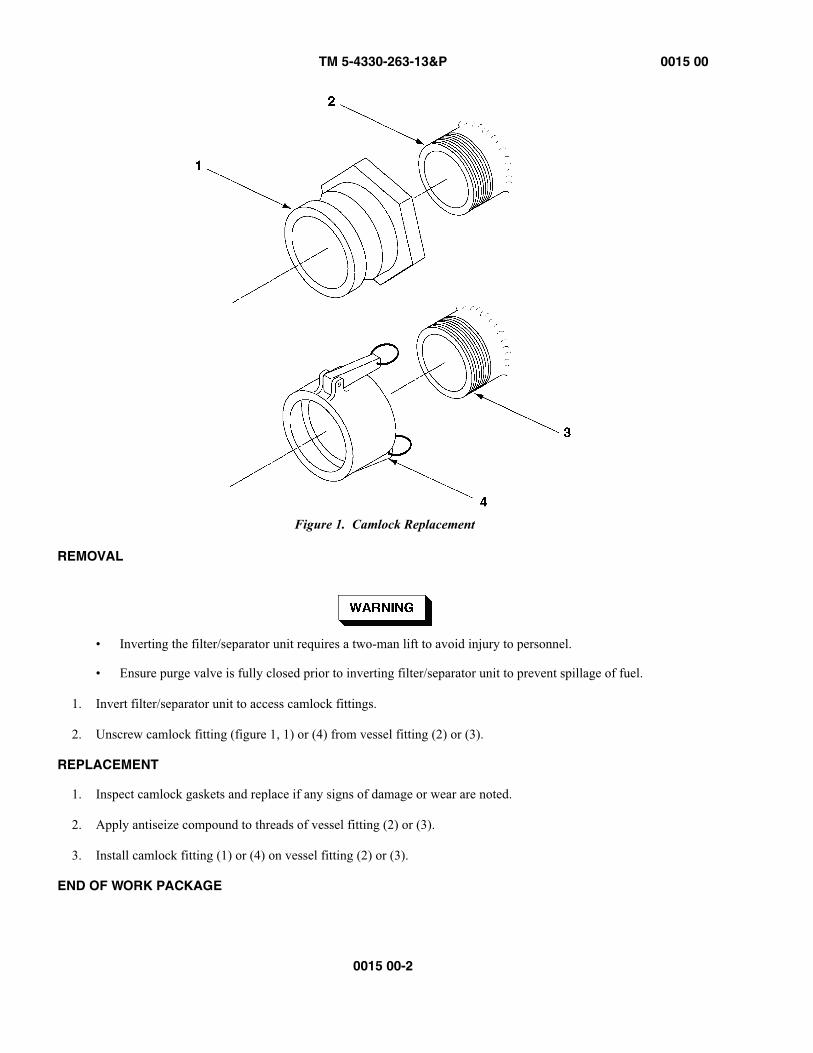
Figure 1. Camlock Replacement
REMOVAL
• Inverting the filter/separator unit requires a two-man lift to avoid injury to personnel.
• Ensure purge valve is fully closed prior to inverting filter/separator unit to prevent spillage of fuel.
1. Invert filter/separator unit to access camlock fittings.
2. Unscrew camlock fitting (figure 1, 1) or (4) from vessel fitting (2) or (3).
REPLACEMENT
1. Inspect camlock gaskets and replace if any signs of damage or wear are noted.
2. Apply antiseize compound to threads of vessel fitting (2) or (3).
3. Install camlock fitting (1) or (4) on vessel fitting (2) or (3).
END OF WORK PACKAGE
TM 5-4330-263-13&P 0016 00
0016 00-1/(0016 00-2 blank)
EQUIPMENT MANUALFILTER/SEPARATOR, LIQUID FUEL, 50-, 100-, AND 350-GPM
REFERENCES
SCOPE
This work package contains all forms, pamphlets, and technical manuals referenced in this manual.
FORMS
SF 364 Report of Discrepancies
SF 368 Product Quality Deficiency Report
PAMPHLETS
DA PAM738-750 Functional Users Manual for the Army Maintenance Management System (TAMMS)
TECHNICAL MANUALS
TM 750-244-3 Procedures for Destruction of Equipment to Prevent Enemy Use
END OF WORK PACKAGE

TM 5-4330-263-13&P 0017 00
0017 00-1
EQUIPMENT MANUALFILTER/SEPARATOR, LIQUID FUEL, 50-, 100-, AND 350-GPM
MAINTENANCE ALLOCATION CHART INTRODUCTION
THE ARMY MAINTENANCE SYSTEM MAC
This introduction provides a general explanation of all maintenance and repair functions authorized at the two mainte-nance levels under the Two-Level Maintenance System concept.
This MAC designates overall authority and responsibility for the performance of maintenance functions on the identified end item or component. The application of the maintenance functions to the end item or component shall be consistent with the capacities and capabilities of the designated maintenance levels, which are shown on the MAC in column (4) as:
Field – includes three subcolumns, Crew maintenance (C), Service maintenance(O), and Field maintenance (F).
Sustainment – includes two subcolumns, Below Depot (H) and Depot (D)
The tools and test equipment requirements (immediately following the MAC) list the tools and test equipment (both spe-cial tools and common tool sets) required for each maintenance function as referenced from the MAC.
The remarks (immediately following the tools and test equipment requirements) contain supplemental instructions and explanatory notes for a particular maintenance function.
Maintenance Functions
Maintenance functions are limited to and defined as follows:
1. Inspect. To determine the serviceability of an item by comparing its physical, mechanical, and/or electrical char-acteristics with established standards through examination (e.g., by sight, sound, or feel). This includes scheduled inspection and gagings and evaluation of cannon tubes.
2. Test. To verify serviceability by measuring the mechanical, pneumatic, hydraulic, or electrical characteristics of an item and comparing those characteristics with prescribed standards on a scheduled basis, i.e., load testing of lift devices and hydrostatic testing of pressure hoses.
3. Service. Operations required periodically to keep an item in proper operating condition; e.g., to clean (includes decontaminate, when required), to preserve, to drain, to paint, or to replenish fuel, lubricants, chemical fluids, or gases. This includes scheduled exercising and purging of recoil mechanisms. The following are examples of ser-vice functions:
a. Unpack. To remove from packing box for service or when required for the performance of maintenanceoperations.
b. Repack. To return item to packing box after service and other maintenance operations.
c. Clean. To rid the item of contamination.
d. Touch up. To spot paint scratched or blistered surfaces.
e. Mark. To restore obliterated identification.

TM 5-4330-263-13&P 0017 00
0017 00-2
4. Adjust. To maintain or regulate, within prescribed limits, by bringing into proper position, or by setting the oper-ating characteristics to specified parameters.
5. Align. To adjust specified variable elements of an item to bring about optimum or desired performance.
6. Calibrate. To determine and cause corrections to be made or to be adjusted on instruments of test, measuring, and diagnostic equipment used in precision measurement. Consists of comparisons of two instruments, one of which is a certified standard of known accuracy, to detect and adjust any discrepancy in the accuracy of the instrument being compared.
7. Remove/Install. To remove and install the same item when required to perform service or other maintenance func-tions. Install may be the act of emplacing, seating, or fixing into position a spare, repair part, or module (compo-nent or assembly) in a manner to allow the proper functioning of an equipment or system.
8. Paint (ammunition only). To prepare and spray color coats of paint so that the ammunition can be identified and protected. The color indicating primary use is applied, preferably, to the entire exterior surface as the background color of the item. Other markings are to be repainted as original so as to retain proper ammunition identification.
9. Replace. To remove an unserviceable item and install a serviceable counterpart in its place “Replace” is autho-rized by the MAC and assigned maintenance level is shown as the third position code of the Source, Maintenance and Recoverability (SMR) code.
10. Repair. The application of maintenance services, including fault location/troubleshooting, removal/installation, disassembly/assembly procedures and maintenance actions to identify troubles and restore serviceability to an item by correcting specific damage, fault, malfunction, or failure in a part, subassembly, module (component or assembly), end item, or system.
NOTEThe following definitions are applicable to the “repair” maintenance function: Services. Inspect, test,service, adjust, align, calibrate, and/or replace.
Fault location/troubleshooting. The process of investigating and detecting the case of equipmentmalfunctioning; the act of isolating a fault within a system or Unit Under Test (UUT).
Disassembly/assembly. The step-by-step breakdown (taking apart) of a spare/functional group codeditem to the level of its least component, that is assigned an SMR code for the level of maintenance underconsideration (i.e., identified as maintenance significant).
Actions. Welding, grinding, riveting, straightening, facing, machining, and/or resurfacing
11. Overhaul. That maintenance effort (service/action) prescribed to restore an item to a completely serviceable/oper-ational condition as required by maintenance standards in appropriate technical publications. Overhaul is nor-mally the highest degree of maintenance performed by the Army. Overhaul des not normally return an item to like new condition.
12. Rebuild. Consists of those services/actions necessary for the restoration of unserviceable equipment to a like new condition in accordance with original manufacturing standards. Rebuild is the highest degree of material mainte-nance applied to Army equipment. The rebuild operation includes the act of returning to zero those age measure-ments (e.g., hours/miles) considered in classifying Army equipment/components.
Explanation of Columns in the MAC
Column (1) Group Number. Column (1) lists Functional Group Code (FGC) numbers, the purpose of which is to identify maintenance significant components, assemblies, subassemblies, and modules with the Next Higher Assembly (NHA).
TM 5-4330-263-13&P 0017 00
0017 00-3
Column (2) Component/Assembly. Column (2) contains the item names of components, assemblies, subassemblies, and modules for which maintenance is authorized.
Column (3) Maintenance Function. Column (3) lists the functions to be performed on the item listed in column (2). (For a detailed explanation of these functions refer to “Maintenance Functions” outlined above).
Column (4) Maintenance Level. Column (4) specifies each level of maintenance authorized to perform each function listed in column (3), by indicating work time required (expressed as manhours in whole hours or decimals) in the appro-priate subcolumn. This work time figure represents the active time required to perform that
maintenance function at the indicated level of maintenance. If the number or complexity of the tasks within the listed maintenance function varies at different maintenance levels, appropriate work time figures are to be shown for each level. The work time figure represents the average time required to restore an item (assembly, subassembly,
component, module, end item, or system) to a serviceable condition under typical field operating conditions. This time includes preparation time (including any necessary disassembly/assembly time), troubleshooting/fault location time, and quality assurance time in addition to the time required to perform the specific tasks identified for the maintenance func-tions authorized in the MAC. The symbol designations for the various maintenance levels are as follows:
Field:
C Crew maintenanceO Service maintenanceF Field maintenance
Sustainment:
H Below Depot maintenanceD Depot maintenance
NOTEThe “L” maintenance level is not included in column (4) of the MAC. Functions to this level ofmaintenance are identified by work time figure in the “H” column of column (4), and an associatedreference code is used in the REMARKS column (6). This code is keyed to the remarks and the SRAcomplete repair application is explained there.
Column (5) Tools and Equipment Reference Code. Column (5) specifies, by code, those common tool sets (not individ-ual tools), common Test, Measurement and Diagnostic Equipment (TMDE), and special tools, special TMDE and special support equipment required to perform the designated function. Codes are keyed to the entries in the tools and test equip-ment table.
Column (6) Remarks Code. When applicable, this column contains a letter code, in alphabetical order, which is keyed to the remarks table entries.
Explanation of Columns in the Tools and Test Equipment Requirements
Column (1) Tool or Test Equipment Reference Code. The tool or test equipment reference code correlates with a code used in column (5) of the MAC.
Column (2) Maintenance Level. The lowest level of maintenance authorized to use the tool or test equipment.
Column (3) Nomenclature. Name or identification of the tool or test equipment.
Column (4) National Stock Number (NSN). The NSN of the tool or test equipment.

TM 5-4330-263-13&P 0017 00
0017 00-4
Column (5) Tool Number. The manufacturer's part number, model number, or type number.
Explanation of Columns in the Remarks
Column (1) Remarks Code. The code recorded in column (6) of the MAC.
Column (2) Remarks. This column lists information pertinent to the maintenance function being performed as indicated in the MAC.
END OF WORK PACKAGE

TM 5-4330-263-13&P 0018 00
0018 00-1
EQUIPMENT MANUALFILTER/SEPARATOR, LIQUID FUEL, 50-, 100-, AND 350-GPM
MAINTENANCE ALLOCATION CHART
Table 1. MAC for Filter/Separator Units
GROUP NUMBER
COMPONENT/ASSEMBLY MAINTENANCE FUNCTION
MAINTENANCE LEVELTOOLS AND EQUIPMENT
REF CODE
REMARKSCODE
FIELD SUSTAINMENTCREW SERVICE FIELD BELOW
DEPOTDEPOT
C O F H D
01 50-GPM FILTER/SEP
0101 FRAME AND VESSEL Inspect 0.1Repair 1.0Replace 4.0
0102 AIR PURGE VALVE Inspect 0.1Replace 0.1
0103 HEAD ASSEMBLY Inspect 0.1Replace 0.2 B, D
0104 CANISTERS Inspect 0.1Replace 0.1
0105 COALESCERS Inspect 0.2Replace 0.1
0106 FUEL/WATER DRAIN VALVE
Inspect 0.1
Replace 0.2 ITest 0.1
0107 SIGHT GAUGE Inspect 0.1Replace 0.5
0108 DIFFERENTIAL PRESSURE GAUGE
Inspect 0.1
Replace 0.4
0109 CAMLOCK FITTING Inspect 0.1Replace 0.5 C

TM 5-4330-263-13&P 0018 00
0018 00-2
0010 DETECTOR KIT Inspect 0.1Replace 0.1
02 100-GPM FILTER/SEP
0201 FRAME AND VESSEL Inspect 0.1Repair 1.0Replace 4.0
0202 AIR PURGE VALVE Inspect 0.1Replace 0.1
0203 HEAD ASSEMBLY Inspect 0.1Replace 0.2 B, D
0204 CANISTERS Inspect 0.1Replace 0.1
0205 COALESCERS Inspect 0.2Replace 0.1
0206 FUEL/WATER DRAIN VALVE
Inspect 0.1
Replace 0.2 FTest 0.1
0207 SIGHT GAUGE Inspect 0.1Replace 0.5
0208 DIFFERENTIAL PRESSURE GAUGE
Inspect 0.1
Replace 0.4
0209 CAMLOCK FITTING Inspect 0.1Replace 0.5 C
0210 DETECTOR KIT Inspect 0.1Replace 0.1
Table 1. MAC for Filter/Separator Units, Continued
GROUP NUMBER
COMPONENT/ASSEMBLY MAINTENANCE FUNCTION
MAINTENANCE LEVELTOOLS AND EQUIPMENT
REF CODE
REMARKSCODE
FIELD SUSTAINMENTCREW SERVICE FIELD BELOW
DEPOTDEPOT
C O F H D

TM 5-4330-263-13&P 0018 00
0018 00-3
03 350-GPM FILTER/SEP Inspect
0301 FRAME AND VESSEL Inspect 0.1Repair 1.0Replace 4.0
0302 AIR PURGE VALVE Inspect 0.1Replace 0.1
0303 HEAD ASSEMBLY Inspect 0.1Replace 0.2 E, G, H
0304 CANISTERS Inspect 0.1Replace 0.1 A
0305 COALESCERS Inspect 0.2Replace 0.1
0306 FUEL/WATER DRAIN VALVE
Inspect 0.1
Replace 0.2 FTest 0.1
0307 SIGHT GAUGE Inspect 0.1Replace 0.5
0308 DIFFERENTIAL PRESSURE GAUGE
Inspect 0.1
Replace 0.4
0309 CAMLOCK FITTING Inspect 0.1Replace 0.5 C
0310 DETECTOR KIT Inspect 0.1Replace 0.1
Table 1. MAC for Filter/Separator Units, Continued
GROUP NUMBER
COMPONENT/ASSEMBLY MAINTENANCE FUNCTION
MAINTENANCE LEVELTOOLS AND EQUIPMENT
REF CODE
REMARKSCODE
FIELD SUSTAINMENTCREW SERVICE FIELD BELOW
DEPOTDEPOT
C O F H D

TM 5-4330-263-13&P 0018 00
0018 00-4
END OF WORK PACKAGE
Table 2. Tools and Test Equipment for Filter/Separator Units
TOOL OR TEST EQUIPMENT
REF CODEMAINTENANCE
LEVEL NOMENCLATURE
NATIONALSTOCK
NUMBER TOOL NUMBERA O Socket, bayonet 493X500_SOCKETB F Torque wrench, 3/8” drive 5120-01-524-4399C F Pipe wrench 5120-01-536-7826D F Socket, deep, 1/2” 5120-01-335-0955E F Torque wrench, 1/2” drive 5120-01-430-8547 2952F F Wrench, 1-1/4” 5120-00-228-9517 A-A-1358G F Wrench, 1-5/16” 5120-00-184-8438 A-A-1356H F Socket, 1-5/16” 5120-01-135-0995 11669754I F Wrench, 1” 5120-01-279-3588
TM 5-4330-263-13&P 0019 00
0019 00-1
EQUIPMENT MANUALFILTER/SEPARATOR, LIQUID FUEL, 50-, 100-, AND 350-GPM
REPAIR PARTS AND SPECIAL TOOLS LIST
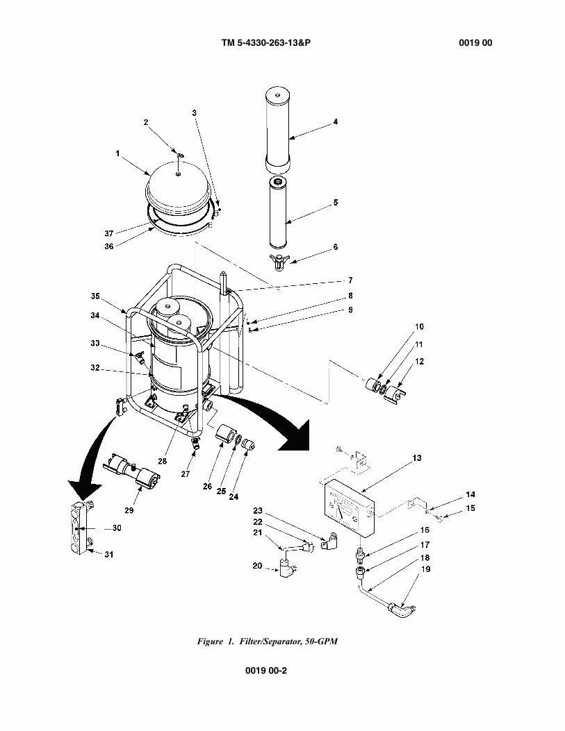
TM 5-4330-263-13&P 0019 00
0019 00-2
Figure 1. Filter/Separator, 50-GPM
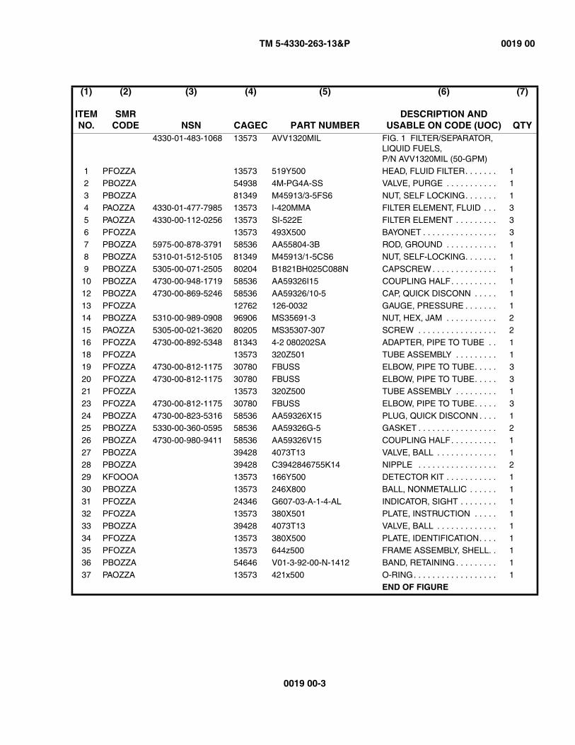
TM 5-4330-263-13&P 0019 00
0019 00-3
(1)
ITEM NO.
(2)
SMR CODE
(3)
NSN
(4)
CAGEC
(5)
PART NUMBER
(6)
DESCRIPTION AND USABLE ON CODE (UOC)
(7)
QTY4330-01-483-1068 13573 AVV1320MIL FIG. 1 FILTER/SEPARATOR,
LIQUID FUELS, P/N AVV1320MIL (50-GPM)
1 PFOZZA 13573 519Y500 HEAD, FLUID FILTER. . . . . . . 1
2 PBOZZA 54938 4M-PG4A-SS VALVE, PURGE . . . . . . . . . . . 1
3 PBOZZA 81349 M45913/3-5FS6 NUT, SELF LOCKING. . . . . . . 14 PAOZZA 4330-01-477-7985 13573 I-420MMA FILTER ELEMENT, FLUID . . . 3
5 PAOZZA 4330-00-112-0256 13573 SI-522E FILTER ELEMENT . . . . . . . . . 3
6 PFOZZA 13573 493X500 BAYONET . . . . . . . . . . . . . . . . 37 PBOZZA 5975-00-878-3791 58536 AA55804-3B ROD, GROUND . . . . . . . . . . . 1
8 PBOZZA 5310-01-512-5105 81349 M45913/1-5CS6 NUT, SELF-LOCKING. . . . . . . 1
9 PBOZZA 5305-00-071-2505 80204 B1821BH025C088N CAPSCREW . . . . . . . . . . . . . . 110 PBOZZA 4730-00-948-1719 58536 AA59326I15 COUPLING HALF. . . . . . . . . . 1
12 PBOZZA 4730-00-869-5246 58536 AA59326/10-5 CAP, QUICK DISCONN . . . . . 1
13 PFOZZA 12762 126-0032 GAUGE, PRESSURE . . . . . . . 114 PBOZZA 5310-00-989-0908 96906 MS35691-3 NUT, HEX, JAM . . . . . . . . . . . 2
15 PAOZZA 5305-00-021-3620 80205 MS35307-307 SCREW . . . . . . . . . . . . . . . . . 2
16 PFOZZA 4730-00-892-5348 81343 4-2 080202SA ADAPTER, PIPE TO TUBE . . 118 PFOZZA 13573 320Z501 TUBE ASSEMBLY . . . . . . . . . 1
19 PFOZZA 4730-00-812-1175 30780 FBUSS ELBOW, PIPE TO TUBE. . . . . 3
20 PFOZZA 4730-00-812-1175 30780 FBUSS ELBOW, PIPE TO TUBE. . . . . 321 PFOZZA 13573 320Z500 TUBE ASSEMBLY . . . . . . . . . 1
23 PFOZZA 4730-00-812-1175 30780 FBUSS ELBOW, PIPE TO TUBE. . . . . 3
24 PBOZZA 4730-00-823-5316 58536 AA59326X15 PLUG, QUICK DISCONN . . . . 125 PBOZZA 5330-00-360-0595 58536 AA59326G-5 GASKET . . . . . . . . . . . . . . . . . 2
26 PBOZZA 4730-00-980-9411 58536 AA59326V15 COUPLING HALF. . . . . . . . . . 1
27 PBOZZA 39428 4073T13 VALVE, BALL . . . . . . . . . . . . . 128 PBOZZA 39428 C3942846755K14 NIPPLE . . . . . . . . . . . . . . . . . 2
29 KFOOOA 13573 166Y500 DETECTOR KIT . . . . . . . . . . . 1
30 PBOZZA 13573 246X800 BALL, NONMETALLIC . . . . . . 1
31 PFOZZA 24346 G607-03-A-1-4-AL INDICATOR, SIGHT . . . . . . . . 132 PFOZZA 13573 380X501 PLATE, INSTRUCTION . . . . . 1
33 PBOZZA 39428 4073T13 VALVE, BALL . . . . . . . . . . . . . 1
34 PFOZZA 13573 380X500 PLATE, IDENTIFICATION. . . . 135 PFOZZA 13573 644z500 FRAME ASSEMBLY, SHELL. . 1
36 PBOZZA 54646 V01-3-92-00-N-1412 BAND, RETAINING. . . . . . . . . 1
37 PAOZZA 13573 421x500 O-RING. . . . . . . . . . . . . . . . . . 1END OF FIGURE
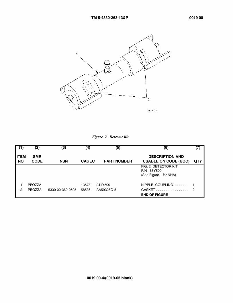
TM 5-4330-263-13&P 0019 00
0019 00-4/(0019-05 blank)
Figure 2. Detector Kit
(1)
ITEM NO.
(2)
SMR CODE
(3)
NSN
(4)
CAGEC
(5)
PART NUMBER
(6)
DESCRIPTION AND USABLE ON CODE (UOC)
(7)
QTYFIG. 2 DETECTOR KITP/N 166Y500(See Figure 1 for NHA)
1 PFOZZA 13573 241Y500 NIPPLE, COUPLING. . . . . . . . 12 PBOZZA 5330-00-360-0595 58536 AA59326G-5 GASKET . . . . . . . . . . . . . . . . . 2
END OF FIGURE

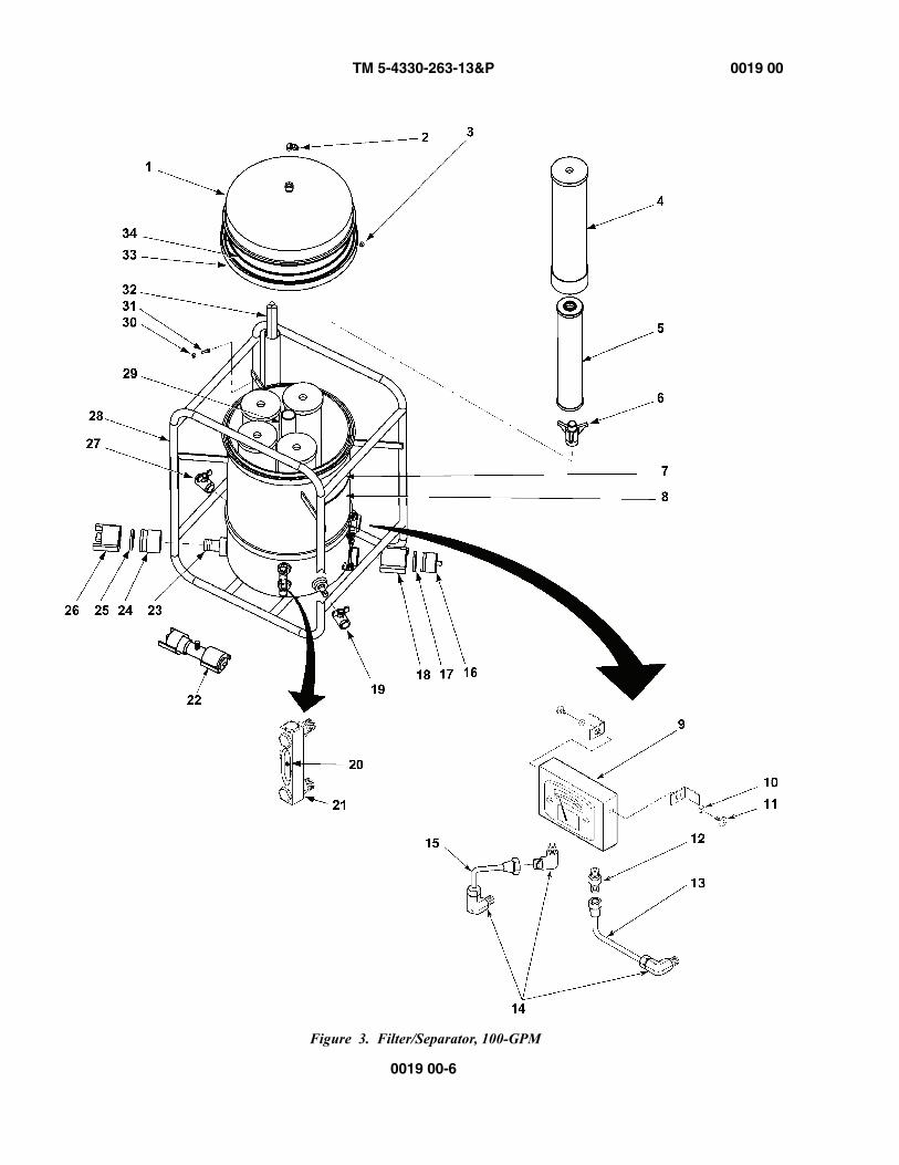
TM 5-4330-263-13&P 0019 00
0019 00-6
Figure 3. Filter/Separator, 100-GPM

TM 5-4330-263-13&P 0019 00
0019 00-7
(1)
ITEM NO.
(2)
SMR CODE
(3)
NSN
(4)
CAGEC
(5)
PART NUMBER
(6)
DESCRIPTION AND USABLE ON CODE (UOC)
(7)
QTY4330-01-525-3659 13573 AVV1620MIL FIG. 3 FILTER/SEPARATOR,
LIQUID FUELS, P/N AVV1620MIL (100-GPM)
1 PFOZZA 13573 519Y600 HEAD, FLUID FILTER. . . . . . . 12 PBOZZA 54938 4M-PG4A-SS VALVE, PURGE . . . . . . . . . . . 1
3 PBOZZA 81349 M45913/3-5FS6 NUT, SELF LOCKING. . . . . . . 1
4 PAOZZA 4330-01-477-7985 13573 I-420MMA FILTER ELEMENT, FLUID . . . 55 PAOZZA 4330-00-112-0256 13573 SI-522E FILTER ELEMENT . . . . . . . . . 5
6 PFOZZA 13573 493X500 BAYONET . . . . . . . . . . . . . . . . 5
7 PFOZZA 13573 380X600 PLATE, IDENTIFICATION. . . . 18 PFOZZA 13573 380X601 PLATE, INSTRUCTION . . . . . 1
9 PFOZZA 12762 126-0032 GAUGE, PRESSURE . . . . . . . 1
10 PBOZZA 5310-00-989-0908 96906 MS35691-3 NUT, HEX JAM . . . . . . . . . . . . 211 PAOZZA 5305-00-021-3620 80205 MS35307-307 SCREW . . . . . . . . . . . . . . . . . 2
12 PFOZZA 4730-00-892-5348 81343 4-2 080202SA ADAPTER, PIPE TO TUBE . . 1
13 PFOZZA 13573 320Z601 TUBE ASSEMBLY . . . . . . . . . 114 PFOZZA 4730-00-812-1175 30780 FBUSS ELBOW, PIPE TO TUBE. . . . . 3
15 PFOZZA 13573 320Z600 TUBE ASSEMBLY . . . . . . . . . 1
16 PBOZZA 4730-00-915-5127 58536 AA59326X16 PLUG, QUICK DISCONN . . . . 117 PBOZZA 5330-00-612-2414 58536 AA59326G-6 GASKET . . . . . . . . . . . . . . . . . 1
18 PBOZZA 4730-00-649-9103 58536 AA59326V16 COUPLING HALF. . . . . . . . . . 1
19 PBOZZA 39428 4073T14 VALVE, BALL . . . . . . . . . . . . . 120 PBOZZA 13573 246X800 BALL, FLOAT . . . . . . . . . . . . . 1
21 PFOZZA 24346 G607-03-A-1-4-AL INDICATOR, SIGHT . . . . . . . . 1
22 KFOOOA 13573 166Y600 DETECTOR KIT . . . . . . . . . . . 123 PBOZZA 4730-00-079-1362 96906 MS27020-11 COUPLING HALF. . . . . . . . . . 1
24 PFOZZA 39428 C3942846755K15 NIPPLE, PIPE . . . . . . . . . . . . 2
25 PBOZZA 5330-00-612-2414 58536 AA59326G-6 GASKET . . . . . . . . . . . . . . . . . 126 PBOZZA 4730-00-869-5246 58536 AA59326IX16 CAP, QUICK DISCONN . . . . . 1
27 PBOZZA 39428 4073T14 VALVE, BALL . . . . . . . . . . . . . 1
28 PFOZZA 13573 644Z600 FRAME ASSEMBLY, SHELL. . 1
29 PFOZZA 13573 323Y600 STANDPIPE . . . . . . . . . . . . . . 130 PBOZZA 5310-01-504-5702 81349 90715A125 NUT, SELF-LOCKING. . . . . . . 1
31 PBOZZA 5305-00-071-2505 80204 B1821BH025C088N CAPSCREW . . . . . . . . . . . . . . 1
32 PBOZZA 5975-00-878-3791 58536 AA55804-3B ROD, GROUND . . . . . . . . . . . 133 PBOZZA 54646 V01-3-92-00-N-1745 BAND, RETAINING. . . . . . . . . 1
34 PAOZZA 13573 421X600 O-RING. . . . . . . . . . . . . . . . . . 1
END OF FIGURE
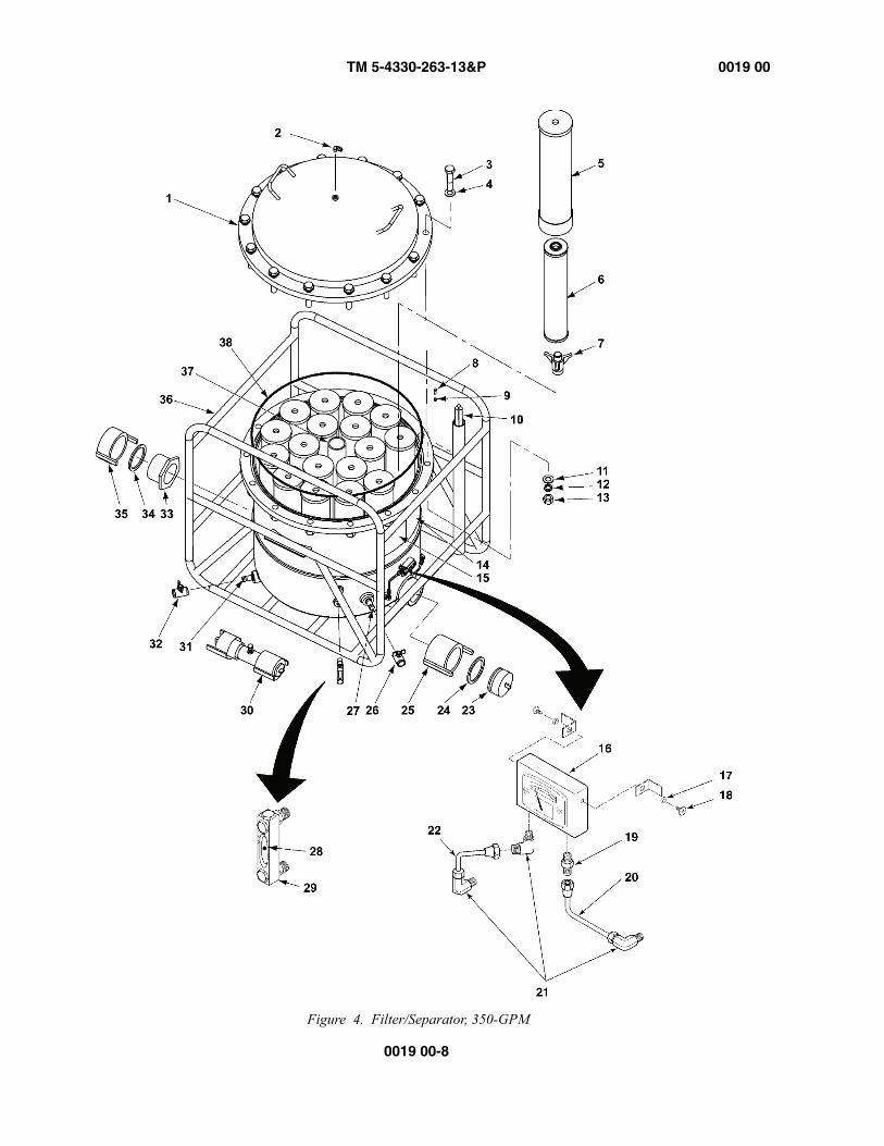
TM 5-4330-263-13&P 0019 00
0019 00-8
Figure 4. Filter/Separator, 350-GPM
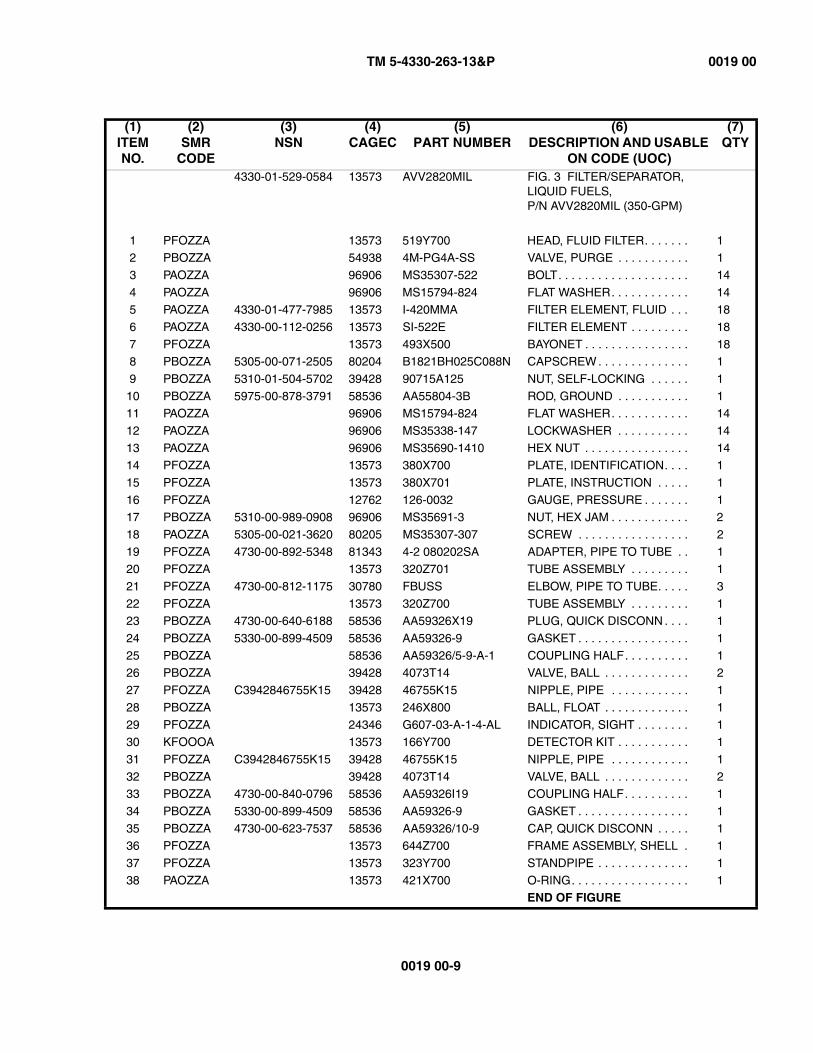
TM 5-4330-263-13&P 0019 00
0019 00-9
(1)ITEM NO.
(2)SMR
CODE
(3)NSN
(4)CAGEC
(5)PART NUMBER
(6)DESCRIPTION AND USABLE
ON CODE (UOC)
(7)QTY
4330-01-529-0584 13573 AVV2820MIL FIG. 3 FILTER/SEPARATOR, LIQUID FUELS, P/N AVV2820MIL (350-GPM)
1 PFOZZA 13573 519Y700 HEAD, FLUID FILTER. . . . . . . 12 PBOZZA 54938 4M-PG4A-SS VALVE, PURGE . . . . . . . . . . . 1
3 PAOZZA 96906 MS35307-522 BOLT. . . . . . . . . . . . . . . . . . . . 14
4 PAOZZA 96906 MS15794-824 FLAT WASHER. . . . . . . . . . . . 145 PAOZZA 4330-01-477-7985 13573 I-420MMA FILTER ELEMENT, FLUID . . . 18
6 PAOZZA 4330-00-112-0256 13573 SI-522E FILTER ELEMENT . . . . . . . . . 18
7 PFOZZA 13573 493X500 BAYONET . . . . . . . . . . . . . . . . 188 PBOZZA 5305-00-071-2505 80204 B1821BH025C088N CAPSCREW . . . . . . . . . . . . . . 1
9 PBOZZA 5310-01-504-5702 39428 90715A125 NUT, SELF-LOCKING . . . . . . 1
10 PBOZZA 5975-00-878-3791 58536 AA55804-3B ROD, GROUND . . . . . . . . . . . 111 PAOZZA 96906 MS15794-824 FLAT WASHER. . . . . . . . . . . . 14
12 PAOZZA 96906 MS35338-147 LOCKWASHER . . . . . . . . . . . 14
13 PAOZZA 96906 MS35690-1410 HEX NUT . . . . . . . . . . . . . . . . 1414 PFOZZA 13573 380X700 PLATE, IDENTIFICATION. . . . 1
15 PFOZZA 13573 380X701 PLATE, INSTRUCTION . . . . . 1
16 PFOZZA 12762 126-0032 GAUGE, PRESSURE . . . . . . . 117 PBOZZA 5310-00-989-0908 96906 MS35691-3 NUT, HEX JAM . . . . . . . . . . . . 2
18 PAOZZA 5305-00-021-3620 80205 MS35307-307 SCREW . . . . . . . . . . . . . . . . . 2
19 PFOZZA 4730-00-892-5348 81343 4-2 080202SA ADAPTER, PIPE TO TUBE . . 120 PFOZZA 13573 320Z701 TUBE ASSEMBLY . . . . . . . . . 1
21 PFOZZA 4730-00-812-1175 30780 FBUSS ELBOW, PIPE TO TUBE. . . . . 3
22 PFOZZA 13573 320Z700 TUBE ASSEMBLY . . . . . . . . . 123 PBOZZA 4730-00-640-6188 58536 AA59326X19 PLUG, QUICK DISCONN . . . . 1
24 PBOZZA 5330-00-899-4509 58536 AA59326-9 GASKET . . . . . . . . . . . . . . . . . 1
25 PBOZZA 58536 AA59326/5-9-A-1 COUPLING HALF. . . . . . . . . . 126 PBOZZA 39428 4073T14 VALVE, BALL . . . . . . . . . . . . . 2
27 PFOZZA C3942846755K15 39428 46755K15 NIPPLE, PIPE . . . . . . . . . . . . 1
28 PBOZZA 13573 246X800 BALL, FLOAT . . . . . . . . . . . . . 1
29 PFOZZA 24346 G607-03-A-1-4-AL INDICATOR, SIGHT . . . . . . . . 130 KFOOOA 13573 166Y700 DETECTOR KIT . . . . . . . . . . . 1
31 PFOZZA C3942846755K15 39428 46755K15 NIPPLE, PIPE . . . . . . . . . . . . 1
32 PBOZZA 39428 4073T14 VALVE, BALL . . . . . . . . . . . . . 233 PBOZZA 4730-00-840-0796 58536 AA59326I19 COUPLING HALF. . . . . . . . . . 1
34 PBOZZA 5330-00-899-4509 58536 AA59326-9 GASKET . . . . . . . . . . . . . . . . . 1
35 PBOZZA 4730-00-623-7537 58536 AA59326/10-9 CAP, QUICK DISCONN . . . . . 136 PFOZZA 13573 644Z700 FRAME ASSEMBLY, SHELL . 1
37 PFOZZA 13573 323Y700 STANDPIPE . . . . . . . . . . . . . . 1
38 PAOZZA 13573 421X700 O-RING. . . . . . . . . . . . . . . . . . 1END OF FIGURE
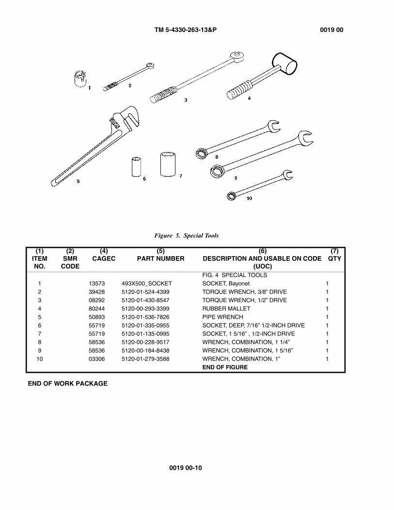
TM 5-4330-263-13&P 0019 00
0019 00-10
Figure 5. Special Tools
END OF WORK PACKAGE
(1)ITEM NO.
(2)SMR
CODE
(4)CAGEC
(5)PART NUMBER
(6)DESCRIPTION AND USABLE ON CODE
(UOC)
(7)QTY
FIG. 4 SPECIAL TOOLS
1 13573 493X500_SOCKET SOCKET, Bayonet 1
2 39428 5120-01-524-4399 TORQUE WRENCH, 3/8” DRIVE 13 08292 5120-01-430-8547 TORQUE WRENCH, 1/2” DRIVE 1
4 80244 5120-00-293-3399 RUBBER MALLET 1
5 50893 5120-01-536-7826 PIPE WRENCH 1
6 55719 5120-01-335-0955 SOCKET, DEEP, 7/16” 1/2-INCH DRIVE 17 55719 5120-01-135-0995 SOCKET, 1 5/16” , 1/2-INCH DRIVE 1
8 58536 5120-00-228-9517 WRENCH, COMBINATION, 1 1/4” 1
9 58536 5120-00-184-8438 WRENCH, COMBINATION, 1 5/16” 110 03306 5120-01-279-3588 WRENCH, COMBINATION, 1” 1
END OF FIGURE
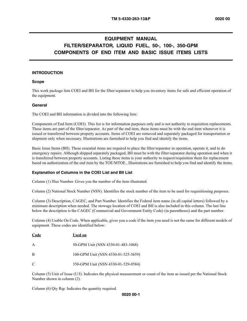
TM 5-4330-263-13&P 0020 00
0020 00-1
EQUIPMENT MANUALFILTER/SEPARATOR, LIQUID FUEL, 50-, 100-, 350-GPM
COMPONENTS OF END ITEM AND BASIC ISSUE ITEMS LISTS
INTRODUCTION
Scope
This work package lists COEI and BII for the filter/separator to help you inventory items for safe and efficient operation of the equipment.
General
The COEI and BII information is divided into the following lists:
Components of End Item (COEI). This list is for information purposes only and is not authority to requisition replacements. These items are part of the filter/separator. As part of the end item, these items must be with the end item whenever it is issued or transferred between property accounts. Items of COEI are removed and separately packaged for transportation or shipment only when necessary. Illustrations are furnished to help you find and identify the items.
Basic Issue Items (BII). These essential items are required to place the filter/separator in operation, operate it, and to do emergency repairs. Although shipped separately packaged, BII must be with the filter/separator during operation and when it is transferred between property accounts. Listing these items is your authority to request/requisition them for replacement based on authorization of the end item by the TOE/MTOE., Illustrations are furnished to help you find and identify the items.
Explanation of Columns in the COEI List and BII List
Column (1) Illus Number. Gives you the number of the item illustrated.
Column (2) National Stock Number (NSN). Identifies the stock number of the item to be used for requisitioning purposes.
Column (3) Description, CAGEC, and Part Number. Identifies the Federal item name (in all capital letters) followed by a minimum description when needed. The stowage location of COEI and BII is also included in this column. The last line below the description is the CAGEC (Commercial and Government Entity Code) (in parentheses) and the part number.
Column (4) Usable On Code. When applicable, gives you a code if the item you need is not the same for different models of equipment. These codes are identified below:
Code Used on
A 50-GPM Unit (NSN 4330-01-483-1068)
B 100-GPM Unit (NSN 4330-01-525-3659)
C 350-GPM Unit (NSN 4330-01-529-0584)
Column (5) Unit of Issue (U/I). Indicates the physical measurement or count of the item as issued per the National Stock Number shown in column (2).
Column (6) Qty Rqr. Indicates the quantity required.
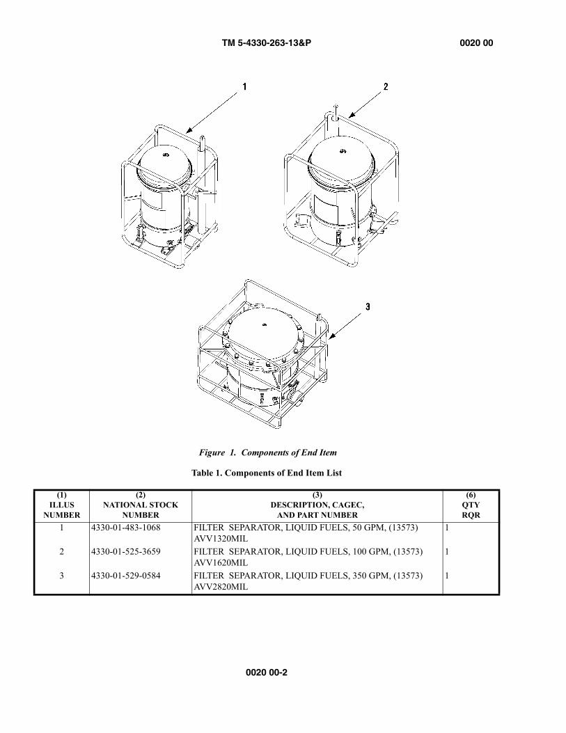
TM 5-4330-263-13&P 0020 00
0020 00-2
Figure 1. Components of End Item
Table 1. Components of End Item List
(1)ILLUS
NUMBER
(2)NATIONAL STOCK
NUMBER
(3)DESCRIPTION, CAGEC,
AND PART NUMBER
(6)QTYRQR
1 4330-01-483-1068 FILTER SEPARATOR, LIQUID FUELS, 50 GPM, (13573) AVV1320MIL
1
2 4330-01-525-3659 FILTER SEPARATOR, LIQUID FUELS, 100 GPM, (13573) AVV1620MIL
1
3 4330-01-529-0584 FILTER SEPARATOR, LIQUID FUELS, 350 GPM, (13573) AVV2820MIL
1
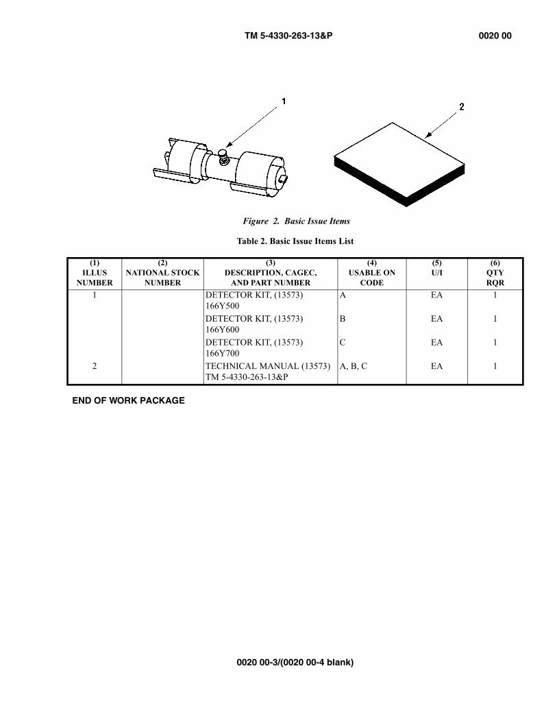
TM 5-4330-263-13&P 0020 00
0020 00-3/(0020 00-4 blank)
Figure 2. Basic Issue Items
END OF WORK PACKAGE
Table 2. Basic Issue Items List
(1)ILLUS
NUMBER
(2)NATIONAL STOCK
NUMBER
(3)DESCRIPTION, CAGEC,
AND PART NUMBER
(4)USABLE ON
CODE
(5)U/I
(6)QTYRQR
1 DETECTOR KIT, (13573) 166Y500
A EA 1
DETECTOR KIT, (13573) 166Y600
B EA 1
DETECTOR KIT, (13573) 166Y700
C EA 1
2 TECHNICAL MANUAL (13573) TM 5-4330-263-13&P
A, B, C EA 1

TM 5-4330-263-13&P 0021 00
0021 00-1/(0021 00-2 blank)
EQUIPMENT MANUALFILTER/SEPARATOR, LIQUID FUEL, 50-, 100-, 350-GPM
ADDITIONAL AUTHORIZATION LIST
There are no additional authorized items for the filter/separators.
END OF WORK PACKAGE

TM 5-4330-263-13&P 0022 00
0022 00-1/(0022 00-2 blank)
EQUIPMENT MANUALFILTER/SEPARATOR, LIQUID FUEL, 50-, 100-, AND 350-GPM
EXPENDABLE AND DURABLE ITEMS LIST
INTRODUCTION
Scope
This work package lists expendable and durable items that you will need to operate and maintain the (enter equipment/end item name). This list is for information only and is not authority to requisition the listed items. These items are authorized to you by CTA 50-970, Expendable/Durable Items (Except Medical, Class V Repair Parts, and Heraldic Items), or CTA 8-100, Army Medical Department Expendable/Durable Items.
Explanation of Columns in the Expendable/Durable Items List
Column (1) Item Number. This number is assigned to the entry in the list and is referenced in the narrative instructions to identify the item (e.g., “Use brake fluid (item 5, WP 0098 00).”).
Column (2) Level. This column identifies the lowest level of maintenance that requires the listed item (include as applicable: C = Operator/Crew, O = Unit/AVUM, F = Direct Support/AVIM, H = General Support, D = Depot).
Column (3) National Stock Number (NSN). This is the NSN assigned to the item which you can use to requisition it.
Column (4) Item Name, Description, Commercial and Government Entity Code (CAGEC), and Part Number (P/N). This column provides the other information you need to identify the item.
Column (5) Unit of Issue (U/I). Indicates the physical measurement or count of the item as issued per the National Stock Number shown in column (3).
END OF WORK PACKAGE
Table 1. Expendable and Durable Items List
(1)ITEM
NUMBER
(2)LEVEL
(3)NATIONAL STOCK
NUMBER
(4)ITEM NAME, DESCRIPTION, CAGEC, AND PART NUMBER
(5)U/I
1 C 7930-00-056-8144 DETERGENT, GENERAL PURPOSE BX2 O COMPOUND, ANTISEIZE (TT-S-1732), 5W425,
P/N NPBT-8CN
3 O 7920-00-044-9281 CLOTH, CLEANING, 51200 BX4 O 4940-01-419-6444 DRIP PAN, METAL, RECTANGULAR, 97403 EA

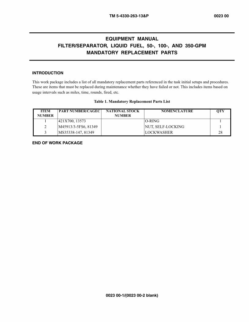
TM 5-4330-263-13&P 0023 00
0023 00-1/(0023 00-2 blank)
EQUIPMENT MANUALFILTER/SEPARATOR, LIQUID FUEL, 50-, 100-, AND 350-GPM
MANDATORY REPLACEMENT PARTS
INTRODUCTION
This work package includes a list of all mandatory replacement parts referenced in the task initial setups and procedures. These are items that must be replaced during maintenance whether they have failed or not. This includes items based on usage intervals such as miles, time, rounds, fired, etc.
END OF WORK PACKAGE
Table 1. Mandatory Replacement Parts List
ITEMNUMBER
PART NUMBER/CAGEC NATIONAL STOCK NUMBER
NOMENCLATURE QTY
1 421X700, 13573 O-RING 12 M45913/3-5FS6, 81349 NUT, SELF-LOCKING 13 MS35338-147, 81349 LOCKWASHER 28


TM 5-4330-263-13&P
INDEX-1
INDEX
A
A-A-52557 ....................................................................................................................................WP 0002–8AAL ...........................................................................................................................................WP 00021–1Additional Authorization List ..........................................................................................................WP 00021–1AR 700-138 ...................................................................................................................................WP 0001–2
B
Basic Issue Items ..........................................................................................................................WP 00020–1Bayonet
Description .........................................................................................................WP 0002–3, WP 0002–5Replacement ..........................................................................................................................WP 00014–1
Bayonet MountDescription ..............................................................................................................................WP 0002–7
BII .............................................................................................................................................WP 00020–1
C
Camlock Replacement ...................................................................................................................WP 00015–1Canister
Description ..............................................................................................................................WP 0002–7Canister Description ...................................................................................................WP 0002–3, WP 0002–5Capabilities ....................................................................................................................................WP 0002–1Coalescer
Description ....................................................................................WP 0002–3, WP 0002–5, WP 0002–7Replacement ............................................................................................................................WP 0009–1
COEI ..........................................................................................................................................WP 00020–1Components of End Item ................................................................................................................WP 00020–1Controls and Indicators ....................................................................................................................WP 0003–1
Differential Pressure Gauge ........................................................................................................WP 0003–3Fuel Drain Valve ......................................................................................................................WP 0003–3Purge Valve .............................................................................................................................WP 0003–3Sight Gauge .............................................................................................................................WP 0003–3Water Drain Valve ....................................................................................................................WP 0003–3
Corrosion Prevention and Control ......................................................................................................WP 0001–2
D
DA PAM738-750 ............................................................................................................................WP 0001–2DA PAM738-751 ............................................................................................................................WP 0001–2Daily Maintenance ..........................................................................................................................WP 0004–2DAPAM738-750 ............................................................................................................................WP 0001–2
TM 5-4330-263-13&P
INDEX-2
Destruction of Army Materiel To Prevent Enemy Use ............................................................................WP 0001–2Detector Kit
Description ....................................................................................WP 0002–3, WP 0002–5, WP 0002–7Detector Kit, Use of ........................................................................................................................WP 0006–2Differential Pressure Gauge
Description ....................................................................................WP 0002–3, WP 0002–5, WP 0002–7Functional Description ...............................................................................................................WP 0003–3Inspection ................................................................................................................................WP 0007–1Replacement ..........................................................................................................................WP 00011–1
Dimensions100-GPM unit ..........................................................................................................................WP 0002–8350-GPM unit ..........................................................................................................................WP 0002–950-GPM unit ............................................................................................................................WP 0002–8
Drain Valve, FuelDescription ....................................................................................WP 0002–3, WP 0002–5, WP 0002–7
Drain Valve, WaterDescription ....................................................................................WP 0002–3, WP 0002–5, WP 0002–7
E
EIR ..............................................................................................................................................WP 0001–2Element Replacement ......................................................................................................................WP 0009–1Equipment Characteristics ................................................................................................................WP 0002–1Equipment Improvement Recommendation ..........................................................................................WP 0001–2Equipment Name ............................................................................................................................WP 0001–1Equipment Purpose .........................................................................................................................WP 0001–1Expendable and Durable Items List ..................................................................................................WP 00022–1
F
Frame and VesselDescription .........................................................................................................WP 0002–5, WP 0002–7Inspection ................................................................................................................................WP 0007–1
Fuel Drain ValveDescription .........................................................................................................WP 0002–3, WP 0002–7Functional Description ...............................................................................................................WP 0003–3Replacement ..........................................................................................................................WP 00012–1
Fuel Drain Valve Description ............................................................................................................WP 0002–5Fuels Processed ..............................................................................................................................WP 0002–8
G
Ground RodDescription .........................................................................................................WP 0002–3, WP 0002–5Inspection ................................................................................................................................WP 0007–1Setup ......................................................................................................................................WP 0005–1
Grounding RodDescription ..............................................................................................................................WP 0002–7
TM 5-4330-263-13&P
INDEX-3
H
Head AssemblyDescription ..............................................................................................................................WP 0002–7
Head Assembly Description .........................................................................................WP 0002–3, WP 0002–5
I
Inlet CouplingDescription ..............................................................................................................................WP 0002–7
Inlet Coupling Description ...........................................................................................WP 0002–3, WP 0002–5Inspection .................................................................................................................WP 0004–2, WP 0007–1
M
MAC ..........................................................................................................................................WP 00017–1Maintenance
Bayonet Replacement ..............................................................................................................WP 00014–1Camlock Replacement .............................................................................................................WP 00015–1Daily ......................................................................................................................................WP 0004–2Differential Pressure Gauge Replacement ....................................................................................WP 00011–1Element Replacement ................................................................................................................WP 0009–1Fuel Drain Valve Replacement ..................................................................................................WP 00012–1Monthly ..................................................................................................................................WP 0004–2Purge Valve Replacement .........................................................................................................WP 00013–1Quarterly .................................................................................................................................WP 0007–1Sight Gauge Replacement .........................................................................................................WP 00010–1Water Drain Valve Replacement ................................................................................................WP 00012–1
Maintenance Allocation Chart .........................................................................................................WP 00017–1Maintenance Forms and Records ........................................................................................................WP 0001–2Mandatory Replacement Parts .........................................................................................................WP 00023–1Maximum Flow Rate
100-GPM unit ..........................................................................................................................WP 0002–8350-GPM unit ..........................................................................................................................WP 0002–950-GPM unit ............................................................................................................................WP 0002–8
Maximum Working Pressure100-GPM unit ..........................................................................................................................WP 0002–8350-GPM unit ..........................................................................................................................WP 0002–950-GPM unit ............................................................................................................................WP 0002–8
MIL-DTL-5624 ..............................................................................................................................WP 0002–8MIL-DTL-83133 ............................................................................................................................WP 0002–8Monthly Maintenance ......................................................................................................................WP 0004–2
O
Operating Temperature Range100-GPM unit ..........................................................................................................................WP 0002–8350-GPM unit ..........................................................................................................................WP 0002–950-GPM unit ............................................................................................................................WP 0002–8
TM 5-4330-263-13&P
INDEX-4
Operation ......................................................................................................................................WP 0006–1O-ring
Description .........................................................................................................WP 0002–5, WP 0002–7Outlet Coupling
Description ....................................................................................WP 0002–3, WP 0002–5, WP 0002–7
P
PMCSField .......................................................................................................................................WP 0007–1Operator ..................................................................................................................................WP 0004–1
Preparation for Operation .................................................................................................................WP 0005–1Preventive Maintenance Checks and Services
Field .......................................................................................................................................WP 0007–1Operator ..................................................................................................................................WP 0004–1
Principles of Operation ....................................................................................................................WP 0002–9Purge Valve
Description ....................................................................................WP 0002–3, WP 0002–5, WP 0002–7Functional Description ...............................................................................................................WP 0003–3Replacement ..........................................................................................................................WP 00013–1
Q
Quarterly Maintenance .....................................................................................................................WP 0007–1
R
References ...................................................................................................................................WP 00016–1Repair Parts .................................................................................................................................WP 00019–1Reporting Equipment Improvement Recommendation ............................................................................WP 0001–2
S
Scope ...........................................................................................................................................WP 0001–1SF 368 ..........................................................................................................................................WP 0001–2Sight Gauge
Description ....................................................................................WP 0002–3, WP 0002–5, WP 0002–7Functional Description ...............................................................................................................WP 0003–3Inspection ................................................................................................................................WP 0007–1Replacement ..........................................................................................................................WP 00010–1
Special Tools ........................................................................................................WP 00019–1, WP 00019–9Storage Temperature Range
100-GPM unit ..........................................................................................................................WP 0002–8350-GPM unit ..........................................................................................................................WP 0002–950-GPM unit ............................................................................................................................WP 0002–8
TM 5-4330-263-13&P
INDEX-5/(INDEX-6 blank)
T
TM750-244-2 .................................................................................................................................WP 0001–2Tools, Special .......................................................................................................WP 00019–1, WP 00019–9Troubleshooting .............................................................................................................................WP 0008–1
V
V-BandDescription .........................................................................................................WP 0002–3, WP 0002–5Inspection ................................................................................................................................WP 0007–1
W
Water Drain ValveDescription ..............................................................................................................................WP 0002–7Functional Description ...............................................................................................................WP 0003–3Replacement ..........................................................................................................................WP 00012–1
Water Drain Valve Description .....................................................................................WP 0002–3, WP 0002–5Weight
100-GPM unit ..........................................................................................................................WP 0002–8350-GPM unit ..........................................................................................................................WP 0002–950-GPM unit ............................................................................................................................WP 0002–8


DA FORM 2028, FEB 74 REPLACES DA FORM 2028, 1 DEC 68, WHICH WILL BE USED. APD V4.00
RECOMMENDED CHANGES TO PUBLICATIONS AND BLANK FORMS
Use Part II(reverse)for Repair Parts and Special Tool Lists (RPSTL) and Supply Catalogs/Supply Manuals (SC/SM).
DATE
For use of this form, see AR 25-30; the proponent agency is OAASA
TO: (Forward to proponent of publication or form) (Include ZIP Code) FROM: (Activity and location) (Include ZIP Code)
PART I - ALL PUBLICATIONS (EXCEPT RPSTL AND SC/SM) AND BLANK FORMS PUBLICATION/FORM NUMBER DATE TITLE
ITEM PAGE PARA- LINE FIGURE NO.
TABLE RECOMMENDED CHANGES AND REASON
TYPED NAME, GRADE OR TITLE TELEPHONE EXCHANGE/AUTOVON, PLUS EXTENSION
SIGNATURE
APD V4.00
TO: (Forward direct to addressee listed in publication) FROM: (Activity and location) (Include ZIP Code) DATE
PART II - REPAIR PARTS AND SPECIAL TOOL LISTS AND SUPPLY CATALOGS/SUPPLY MANUALS
PUBLICATION NUMBER DATE TITLE
PAGE NO.
COLM NO.
LINE NO.
NATIONAL STOCK NUMBER
REFERENCENO.
FIGURE NO.
ITEM NO.
TOTAL NO. OF MAJOR ITEMS
SUPPORTED
RECOMMENDED ACTION
PART III - REMARKS (Any genera/ remarks or recommendations, or suggestions for improvement of publications and blank forms. Additional blank sheets may be used if more space is needed.)
TYPED NAME, GRADE OR TITLE TELEPHONE EXCHANGE/AUTOVON, PLUS EXTENSION
SIGNATURE
RECOMMENDED CHANGES TO PUBLICATIONS ANDBLANK FORMS
For use of this form, see AR 310-1; the proponent agency is the US Army Adjutant General Center.
Use Part II (reverse) for Repair Parts and Special Tool Lists (RPSTL) and Supply Catalogs/Supply Manuals (SC/SM).
DATE
TO: (Forward to proponent of publication or form) (Include ZIP Code) FROM: (Activity and location) (Include ZIP Code)
PART I - ALL PUBLICATIONS (EXCEPT RPSTL AND SC/SM) AND BLANK FORMS PUBLICATION/FORM NUMBER DATE TITLE
ITEMNO.
PAGE NO.
PARA-GRAPH
LINENO.*
FIGURENO.
TABLENO.
RECOMMENDED CHANGES AND REASON(Exact wording of recommended change must be given)
* Reference to line numbers within the paragraph or subparagraph. TYPED NAME, GRADE OR TITLE TELEPHONE EXCHANGE/AUTOVON,
PLUS EXTENSION SIGNATURE
DA FORM1 FEB 74 2028 REPLACES DA FORM 2028, 1 DEC 68, WHICH WILL BE USED.
TO: (Forward to proponent of publication or form) (Include ZIP Code) FROM: (Activity and location) (Include ZIP Code) DATE
PART II- REPAIR PARTS AND SPECIAL TOOL LISTS AND SUPPLY CATALOGS/SUPPLY MANUALS PUBLICATION/FORM NUMBER DATE TITLE
PAGE NO.
COLMNO.
LINENO.
FEDERAL STOCK NUMBER
REFERENCENO.
FIGURENO.
ITEMNO.
TOTAL NO. OF MAJOR
ITEMSSUPPROTED
RECOMMENDED ACTION
PART III - REMARKS (Any general remarks or recommendations, or suggestions for improvement of publications andblank forms. Additional blank sheets may be used if more space is needed.)
TYPED NAME, GRADE OR TITLE TELEPHONE EXCHANGE/AUTOVON, PLUS EXTENSION
SIGNATURE
U.S. GOVERNMENT PRINTING OFFICE 1981 341-646/8606

Distribution:
To be distributed in accordance with the Initial Distribution Number (IDN) 256974 requirements for TM 10-4930-361-14.
By Order of the Secretary of the Army:
JOYCE E. MORROWAdministrative Assistant to the
Secretary of the Army
0819806
GEORGE W. CASEY, JR.General, United States Army
Chief of Staff
Official:
TM 10-4930-361-14

LINEAR MEASURE1 Centimeter = 10 Millimeters = 0.01 Meters =
0.3937 Inches1 Meter = 100 Centimeters = 1,000 Millimeters =
39.37 Inches1 Kilometer = 1,000 Meters = 0.621 Miles
SQUARE MEASURE1 Sq Centimeter = 100 Sq Millimeters = 0.155 Sq Inches1 Sq Meter = 10,000 Sq Centimeters = 10.76 Sq Feet1 Sq Kilometer = 1,000,000 Sq Meters = 0.386 Sq Miles
CUBIC MEASURE1 Cu Centimeter = 1,000 Cu Millimeters = 0.06 Cu Inches1 Cu Meter = 1,000,000 Cu Centimeters = 35.31 Cu Feet
LIQUID MEASURE1 Milliliter = 0.001 Liters = 0.0338 Fluid Ounces1 Liter = 1,000 Milliliters = 33.82 Fluid Ounces
TEMPERATUREDegrees Fahrenheit (F) = ˚C • 9 ÷ 5 + 32Degrees Celsius (C) = F˚ - 32 • 5 ÷ 9212˚ Fahrenheit is equivalent to 100˚ Celsius90˚ Fahrenheit is equivalent to 32.2˚ Celsius32˚ Fahrenheit is equivalent to 0˚ Celsius
WEIGHTS1 Gram = 0.001 Kilograms = 1,000 Milligrams = 0.035 Ounces1 Kilogram = 1,000 Grams = 2.2 Lb1 Metric Ton = 1,000 Kilograms = 1 Megagram = 1.1 Short Tons
THE METRIC SYSTEM AND EQUIVALENTS
APPROXIMATE CONVERSION FACTORSTO CHANGE . . . . . . . . . . . . . . . . . . . . TO . . . . . . . . . . . . . . . . . . . . . . . .MULTIPLY BYInches . . . . . . . . . . . . . . . . . . . . . . . . . Millimeters . . . . . . . . . . . . . . . . . . 25.4Inches . . . . . . . . . . . . . . . . . . . . . . . . . Centimeters . . . . . . . . . . . . . . . . . 2.540Feet . . . . . . . . . . . . . . . . . . . . . . . . . . Meters . . . . . . . . . . . . . . . . . . . . . 0.305Yards . . . . . . . . . . . . . . . . . . . . . . . . . Meters . . . . . . . . . . . . . . . . . . . . . 0.914Miles . . . . . . . . . . . . . . . . . . . . . . . . . . Kilometers . . . . . . . . . . . . . . . . . . 1.609Square Inches . . . . . . . . . . . . . . . . . . Square Centimeters . . . . . . . . . . 6.451Square Feet . . . . . . . . . . . . . . . . . . . . Square Meters . . . . . . . . . . . . . . . 0.093Square Yards . . . . . . . . . . . . . . . . . . . Square Meters . . . . . . . . . . . . . . . 0.836Square Miles . . . . . . . . . . . . . . . . . . . Square Kilometers . . . . . . . . . . . . 2.590Acres . . . . . . . . . . . . . . . . . . . . . . . . . . Square Hectometers . . . . . . . . . . 0.405Cubic Feet . . . . . . . . . . . . . . . . . . . . . Cubic Meters . . . . . . . . . . . . . . . . 0.028Cubic Yards . . . . . . . . . . . . . . . . . . . . Cubic Meters . . . . . . . . . . . . . . . . 0.765Fluid Ounces . . . . . . . . . . . . . . . . . . . Milliliters . . . . . . . . . . . . . . . . . . . 29.573Pints . . . . . . . . . . . . . . . . . . . . . . . . . . Liters . . . . . . . . . . . . . . . . . . . . . . 0.473Quarts . . . . . . . . . . . . . . . . . . . . . . . . Liters . . . . . . . . . . . . . . . . . . . . . . 0.946Gallons . . . . . . . . . . . . . . . . . . . . . . . . Liters . . . . . . . . . . . . . . . . . . . . . . 3.785Ounces . . . . . . . . . . . . . . . . . . . . . . . . Grams . . . . . . . . . . . . . . . . . . . . . . 28.349Pounds . . . . . . . . . . . . . . . . . . . . . . . . Kilograms . . . . . . . . . . . . . . . . . . . 0.4536Short Tons . . . . . . . . . . . . . . . . . . . . . Metric Tons . . . . . . . . . . . . . . . . . 0.907Pound-Feet . . . . . . . . . . . . . . . . . . . . . Newton-Meters . . . . . . . . . . . . . . 1.356Pounds Per Square Inch . . . . . . . . . . Kilopascals . . . . . . . . . . . . . . . . . . 6.895Miles Per Gallon . . . . . . . . . . . . . . . . Kilometers Per Liter . . . . . . . . . . 0.425Miles Per Hour . . . . . . . . . . . . . . . . . Kilometers Per Hour . . . . . . . . . . 1.609
TO CHANGE . . . . . . . . . . . . . . . . . . . . TO . . . . . . . . . . . . . . . . . . . . . . . .MULTIPLY BYMillimeters . . . . . . . . . . . . . . . . . . . . . Inches . . . . . . . . . . . . . . . . . . . . . . 0.03937Centimeters . . . . . . . . . . . . . . . . . . . . Inches . . . . . . . . . . . . . . . . . . . . . . 0.3937Meters . . . . . . . . . . . . . . . . . . . . . . . . Feet . . . . . . . . . . . . . . . . . . . . . . . . 3.280Meters . . . . . . . . . . . . . . . . . . . . . . . . Yards . . . . . . . . . . . . . . . . . . . . . . 1.094Kilometers . . . . . . . . . . . . . . . . . . . . . Miles . . . . . . . . . . . . . . . . . . . . . . . 0.621Square Centimeters . . . . . . . . . . . . . Square Inches . . . . . . . . . . . . . . . 0.155Square Meters . . . . . . . . . . . . . . . . . . Square Feet . . . . . . . . . . . . . . . . . 10.764Square Meters . . . . . . . . . . . . . . . . . . Square Yards . . . . . . . . . . . . . . . . 1.196Square Kilometers . . . . . . . . . . . . . . . Square Miles . . . . . . . . . . . . . . . . 0.386Square Hectometers . . . . . . . . . . . . . Acres . . . . . . . . . . . . . . . . . . . . . . . 2.471Cubic Meters . . . . . . . . . . . . . . . . . . . Cubic Feet . . . . . . . . . . . . . . . . . . 35.315Cubic Meters . . . . . . . . . . . . . . . . . . . Cubic Yards . . . . . . . . . . . . . . . . . 1.308Milliliters . . . . . . . . . . . . . . . . . . . . . . Fluid Ounces . . . . . . . . . . . . . . . . 0.034Liters . . . . . . . . . . . . . . . . . . . . . . . . . Pints . . . . . . . . . . . . . . . . . . . . . . . 2.113Liters . . . . . . . . . . . . . . . . . . . . . . . . . Quarts . . . . . . . . . . . . . . . . . . . . . 1.057Liters . . . . . . . . . . . . . . . . . . . . . . . . . Gallons . . . . . . . . . . . . . . . . . . . . . 0.264Grams . . . . . . . . . . . . . . . . . . . . . . . . . Ounces . . . . . . . . . . . . . . . . . . . . . 0.035Kilograms . . . . . . . . . . . . . . . . . . . . . . Pounds . . . . . . . . . . . . . . . . . . . . . 2.2046Metric Tons . . . . . . . . . . . . . . . . . . . . Short Tons . . . . . . . . . . . . . . . . . . 1.102Newton-Meters . . . . . . . . . . . . . . . . . Pound-Feet . . . . . . . . . . . . . . . . . . 0.738Kilopascals . . . . . . . . . . . . . . . . . . . . . Pounds Per Square Inch . . . . . . . 0.145Kilometers Per Liter . . . . . . . . . . . . . Miles Per Gallon . . . . . . . . . . . . . 2.354Kilometers Per Hour . . . . . . . . . . . . . Miles Per Hour . . . . . . . . . . . . . . 0.621
�����������
�����
�
�
��
�
��
�
��
��
��
��
��
�
��
��

PIN: 085024-000
This fine document...
Was brought to you by me:
Liberated Manuals -- free army and government manuals
Why do I do it? I am tired of sleazy CD-ROM sellers, who take publicly available information, slap “watermarks” and other junk on it, and sell it. Those masters of search engine manipulation make sure that their sites that sell free information, come up first in search engines. They did not create it... They did not even scan it... Why should they get your money? Why are not letting you give those free manuals to your friends?
I am setting this document FREE. This document was made by the US Government and is NOT protected by Copyright. Feel free to share, republish, sell and so on.
I am not asking you for donations, fees or handouts. If you can, please provide a link to liberatedmanuals.com, so that free manuals come up first in search engines:
<A HREF=http://www.liberatedmanuals.com/>Free Military and Government Manuals</A>
– SincerelyIgor Chudovhttp://igor.chudov.com/
– Chicago Machinery Movers