TM 5-4310-385-13 TECHNICAL MANUAL OPERATOR'S, UNIT, AND ...
120
TM 5-4310-385-13 TECHNICAL MANUAL OPERATOR'S, UNIT, AND INTERMEDIATE DIRECT SUPPORT MAINTENANCE MANUAL COMPRESSOR, RECIPROCATING, AIR: ELECTRIC MOTOR DRIVEN 5 CFM, 175 PSI C & H MODEL 20-918 NSN 4310-01-252-3957 TABLE OF CONTENTS INTRODUCTION OPERATING INSTRUCTIONS UNIT MAINTENANCE INSTRUCTIONS INTERMEDIATE DIRECT SUPPORT MAINTENANCE INSTRUCTIONS APPENDICES INDEX Approved for public release. Distribution is unlimited. HEADQUARTERS, DEPARTMENT OF THE ARMY 30 SEPTEMBER 1987
Transcript of TM 5-4310-385-13 TECHNICAL MANUAL OPERATOR'S, UNIT, AND ...

TM 5-4310-385-13
TECHNICAL MANUAL
OPERATOR'S, UNIT,AND INTERMEDIATE DIRECT SUPPORT
MAINTENANCE MANUAL
COMPRESSOR, RECIPROCATING, AIR:ELECTRIC MOTOR DRIVEN
5 CFM, 175 PSIC & H MODEL 20-918
NSN 4310-01-252-3957
TABLE OFCONTENTS
INTRODUCTION
OPERATINGINSTRUCTIONS
UNIT MAINTENANCEINSTRUCTIONS
INTERMEDIATE DIRECTSUPPORT MAINTENANCE
INSTRUCTIONS
APPENDICES
INDEX
Approved for public release. Distribution is unlimited.
HEADQUARTERS, DEPARTMENT OF THE ARMY30 SEPTEMBER 1987
TM 5-4310-385-13
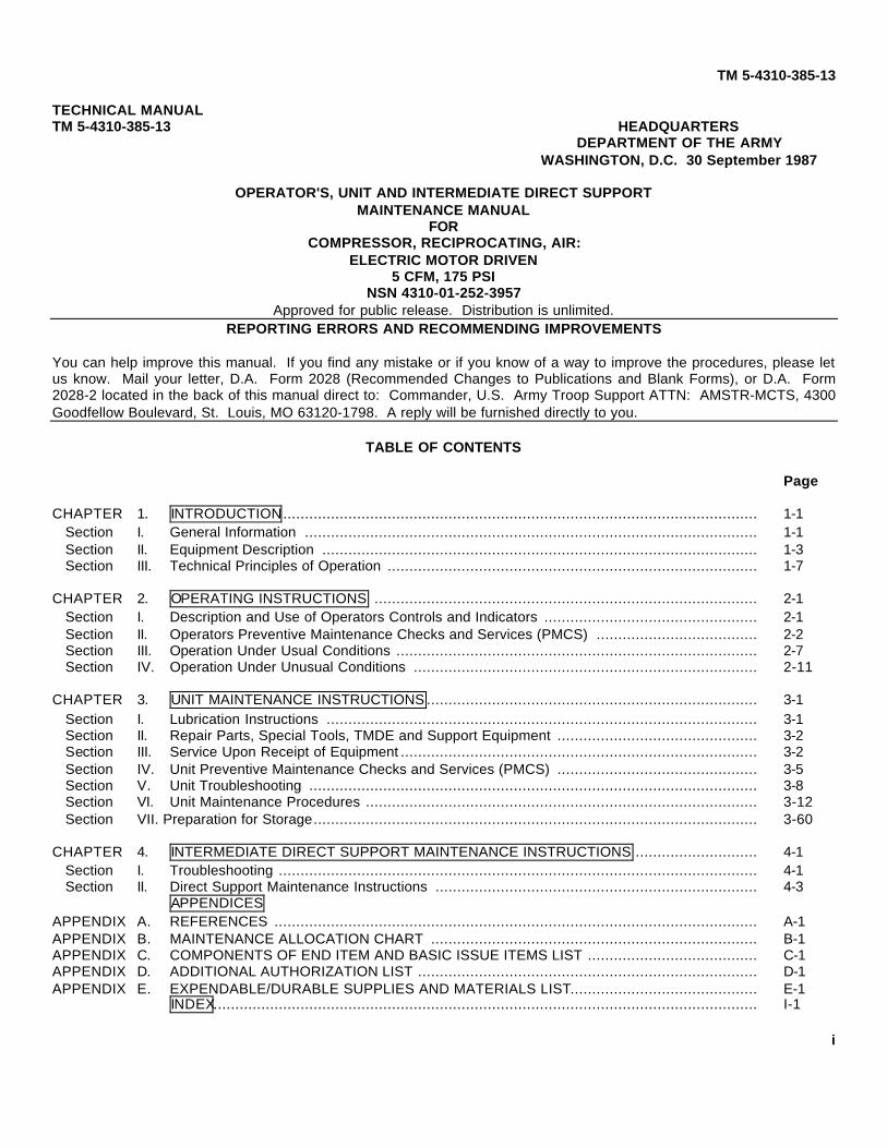
SAFETY WARNINGS
WARNING
Always disconnect electric power from the air compressor before starting anywork on it. The air compressor could start up accidentally and could causeserious injury to maintenance personnel.
WARNING
Never attempt to service any of the air compressor components until the unit isrelieved of all air pressure through the drain cock on bottom of tank.
WARNING
Lethal voltages are present in the circuitry of the air compressor. Disconnectpower from the compressor before starting any repair work.
WARNING
Do not weld the air receiver tank to repair leaks.
WARNING
Do not operate the air compressor with the belt guard removed.
WARNING
Do not operate in a tilted position.
WARNING
The compressed air supplied by this compressor is not breathable and must notbe used to charge cylinders that will be used to supply breathable air.
WARNING
Operation of this equipment presents a noise hazard to personnel in the area. Ifthe noise level exceeds the allowable limits for unprotected personnel, wear earmuffs or earplugs which were fitted by a trained professional.
WARNING
Make certain any lifting device used has a capacity equal to the weight being lifted.Failure to observe this precaution could result in injury or death to personnel anddamage to equipment.
WARNING
Before starting motor or operating any of the components, be sure that no loosebars, tools or parts are lying in or on any of the equipment as they could causeserious damage to equipment or bodily injury to personnel.
WARNING
Never wear loose Clothing or have hanging objects (pull-strings, test wires, etc.)while inspecting or servicing machine in operation. Rotating motor, shafts, andpulleys may entrap personnel and cause serious injury.
a

TM 5-4310-385-13
WARNING
Drycleaning solvent, P-D-680, used to clean parts is potentially dangerous topersonnel and property. Avoid repeated and prolonged skin contact by wearingrubber or non-porous gloves when handling the solvent or material wet withdrycleaning solvent. Wash hands immediately after exposure with soap and waterand use a lanolin based skin cream to prevent skin drying. Do not use near openflame or excessive heat. Flash point of solvent is 100°° F (38°° C). Do not work withsolvent in a closed room. Be sure there is good ventilation or the solvent vaporswill build up in the air and become a poisonous mixture which can cause physicalinjury or even death.
WARNING
Eye protective equipment must be worn when removing rust and loose paint.
WARNING
Clean components with compressed air no greater than 30 psi (2.11 kgcm2). Eyeprotection must be worn when cleaning with compressed air.
b
TM 5-4310-385-13
TECHNICAL MANUALTM 5-4310-385-13 HEADQUARTERS
DEPARTMENT OF THE ARMYWASHINGTON, D.C. 30 September 1987
OPERATOR'S, UNIT AND INTERMEDIATE DIRECT SUPPORTMAINTENANCE MANUAL
FORCOMPRESSOR, RECIPROCATING, AIR:
ELECTRIC MOTOR DRIVEN5 CFM, 175 PSI
NSN 4310-01-252-3957Approved for public release. Distribution is unlimited.
REPORTING ERRORS AND RECOMMENDING IMPROVEMENTS
You can help improve this manual. If you find any mistake or if you know of a way to improve the procedures, please letus know. Mail your letter, D.A. Form 2028 (Recommended Changes to Publications and Blank Forms), or D.A. Form2028-2 located in the back of this manual direct to: Commander, U.S. Army Troop Support ATTN: AMSTR-MCTS, 4300Goodfellow Boulevard, St. Louis, MO 63120-1798. A reply will be furnished directly to you.
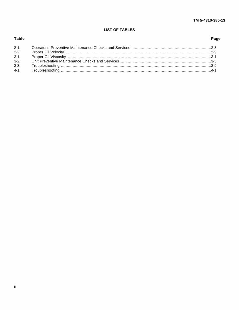
TABLE OF CONTENTS
Page
CHAPTER 1. INTRODUCTION............................................................................................................. 1-1Section I. General Information ........................................................................................................ 1-1Section II. Equipment Description .................................................................................................... 1-3Section III. Technical Principles of Operation ..................................................................................... 1-7
CHAPTER 2. OPERATING INSTRUCTIONS ........................................................................................ 2-1Section I. Description and Use of Operators Controls and Indicators ................................................. 2-1Section II. Operators Preventive Maintenance Checks and Services (PMCS) ..................................... 2-2Section III. Operation Under Usual Conditions ................................................................................... 2-7Section IV. Operation Under Unusual Conditions ............................................................................... 2-11
CHAPTER 3. UNIT MAINTENANCE INSTRUCTIONS ............................................................................ 3-1Section I. Lubrication Instructions ................................................................................................... 3-1Section II. Repair Parts, Special Tools, TMDE and Support Equipment .............................................. 3-2Section III. Service Upon Receipt of Equipment .................................................................................. 3-2Section IV. Unit Preventive Maintenance Checks and Services (PMCS) .............................................. 3-5Section V. Unit Troubleshooting ....................................................................................................... 3-8Section VI. Unit Maintenance Procedures .......................................................................................... 3-12Section VII. Preparation for Storage...................................................................................................... 3-60
CHAPTER 4. INTERMEDIATE DIRECT SUPPORT MAINTENANCE INSTRUCTIONS ............................ 4-1Section I. Troubleshooting .............................................................................................................. 4-1Section II. Direct Support Maintenance Instructions .......................................................................... 4-3
APPENDICESAPPENDIX A. REFERENCES ............................................................................................................... A-1APPENDIX B. MAINTENANCE ALLOCATION CHART ........................................................................... B-1APPENDIX C. COMPONENTS OF END ITEM AND BASIC ISSUE ITEMS LIST ....................................... C-1APPENDIX D. ADDITIONAL AUTHORIZATION LIST .............................................................................. D-1APPENDIX E. EXPENDABLE/DURABLE SUPPLIES AND MATERIALS LIST........................................... E-1
INDEX............................................................................................................................. I-1
i
TM 5-4310-385-13
LIST OF TABLES
Table Page
2-1. Operator's Preventive Maintenance Checks and Services ....................................................................2-32-2. Proper Oil Velocity ............................................................................................................................2-93-1. Proper Oil Viscosity ..........................................................................................................................3-13-2. Unit Preventive Maintenance Checks and Services ..............................................................................3-53-3. Troubleshooting ................................................................................................................................3-94-1. Troubleshooting ................................................................................................................................4-1
ii

TM 5-4310-385-13
STARTER SIDE VIEW
BELT GUARD VIEW
1-0
TM 5-4310-385-13
CHAPTER 1. INTRODUCTION
SECTION I. GENERAL INFORMATION
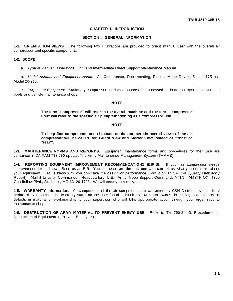
1-1. ORIENTATION VIEWS. The following two illustrations are provided to orient manual user with the overall aircompressor and specific components.
1-2. SCOPE.
a. Type of Manual: Operator's, Unit, and Intermediate Direct Support Maintenance Manual.
b. Model Number and Equipment Name: Air Compressor, Reciprocating, Electric Motor Driven, 5 cfm, 175 psi,Model 20-918.
c. Purpose of Equipment: Stationary compressor used as a source of compressed air in normal operations at motorpools and vehicle maintenance shops.
NOTE
The term "compressor" will refer to the overall machine and the term "compressorunit" will refer to the specific air pump functioning as a compressor unit.
NOTE
To help find components and eliminate confusion, certain overall views of the aircompressor will be called Belt Guard View and Starter View instead of "front" or"rear"'.
1-3. MAINTENANCE FORMS AND RECORDS. Equipment maintenance forms and procedures for their use arecontained in DA PAM 738-750 update, The Army Maintenance Management System (TAMMS).
1-4. REPORTING EQUIPMENT IMPROVEMENT RECOMMENDATIONS (EIR'S). If your air compressor needsimprovement, let us know. Send us an EIR. You, the user, are the only one who can tell us what you don't like aboutyour equipment. Let us know why you don't like the design or performance. Put it on an SF 368 (Quality DeficiencyReport). Mail it to us at Commander, Headquarters, U.S. Army Troop Support Command, ATTN: AMSTR-QX, 4300Goodfellow Blvd., St. Louis, MO 63120-1798. We will send you a reply.
1-5. WARRANTY information. All components of the air compressor are warranted by C&H Distributors Inc. for aperiod of 12 months. The warranty starts on the date found in block 23, DA Form 2408-9, in the logbook. Report alldefects in material or workmanship to your supervisor who will take appropriate action through your organizationalmaintenance shop.
1-6. DESTRUCTION OF ARMY MATERIAL TO PREVENT ENEMY USE. Refer to TM 750-244-3, Procedures forDestruction of Equipment to Prevent Enemy Use.
1-1

TM 5-4310-385-13
1. AIR TANK2. SAFETY RELIEF VALVE3. CHECK VALVE4. AFTERCOOLER TUBING5. INTERCOOLER TUBING Compressor. Starter Side View6. COMPRESSOR UNIT7. ELECTRIC MOTOR8. HOSE RACK9. MOTOR STARTER
10. ON/OFF SWITCH11. RESET BUTTON12. PRESSURE SWITCH13. SHUTOFF VALVE14. AIR HOSE15. UNLOADER LINE16. INFLATOR VALVE ASSEMBLY17. PRESSURE GAUGE18. DRIVE PULLEY19. V-BELTS20. FLYWHEEL21. BELT GUARD
Compressor, Belt Guard View
1-2

TM 5-4310-385-13
SECTION II. EQUIPMENT DESCRIPTION
1-7. PURPOSE OF THE AIR COMPRESSOR. An electric motor driven compressor for tools, tire inflation and generalshop use.
1-8. CAPABILITIES AND FEATURES.
a. Two stage compressor provides compressed air at 5 cfm and 175 psi.
b. Electric motor driven.
c. Magnetic motor starter with thermal relay protects motor against overload.
d. Pressure switch provides for automatic compressor cut-in at 160 psi and cut-out at 190 psi.
e. Tank safety relief valve to prevent damage to compressor and injury to personnel.
f. Automatic unloading of compressor unit upon machine shutdown.
g. Air discharge system with inflator gage can be used to directly inflate tires to proper pressure.
h. Tank mounted pressure gage gives constant reading of air pressure in tank.
1-9. DESCRIPTION OF COMPRESSOR COMPONENTS.
a. Air Tank (1). A 20 gallon air tank with welded boss openings for check valve, pressure gauge, pressure switch,outlet valve, and safety relief valve. Has a welded platform base for electric motor and compressor mounting.
b. Safety Relief Valve (2). Tank mounted valve with relief setting of 200 psi. Pull ring for manual check of operation.
c. Check Valve (3). Spring and poppet valve that prevents air from returning to the compressor head from the tank.Has threaded opening for unloader line fitting.
d. Aftercooler Tubing (4). Air discharge tubing from high pressure cylinder head to check valve and air tank.
e. lntercooler Tubing (5). Finned copper tubing between the high and low pressure cylinder heads. Provides heatdissipation between the high and low pressure cylinder heads.
f. Compressor Unit (6). A two stage air cooled pump driven by pulleys and V-belts. Rated at 5 cfm at 175 psi.
g. Electric Motor (7). Three phase, 2 hp induction motor. Shaft mounted pulley powers larger compressor flywheel.Wired in series with pressure switch and magnetic motor starter.
h. Hose Rack (8). Welded to motor starter frame to provide hose storage.
i. Motor Starter (9). Contacts are magnetically closed when power is applied. Contains a thermal or melting relaywhich opens the circuit when a current overload is sensed. Enclosure contains ON/OFF switch (10) and RESET button(11).
j. Pressure Switch (12). Controls operating pressure range between 160 psi (cut-in) and 190 psi (cut-out) with adifferential of 30 psi. Diaphragm senses operating pressure and opens and closes contacts. Adjustable pressure setting.Contains a pressure relief fitting for the unloader line.
k. Shutoff Valve (13). Hand operated globe valve to shut off air flow from tank to air hoses.
I. Air Hose (14). 50 ft. hose couples to shutoff valve and inflator gauge assembly. Stores on tank hose rack.
m. Unloader Line (15). Runs between check valve and pressure switch. Upon compressor shutdown, providesrelease of air pressure in cylinder heads and aftercooler for easier startup.
n. Inflator Valve and Gauge Assembly (16). Connected to 50 ft. air hoses. Hand lever releases air pressure. Sight glass provided for inflation reading. Quick connect couplings between gauge and inflator valves (one regular tirevalve, one special application valve).
o. Pressure Gauge (17). Provides continuous reading of tank pressure between 0-200 psi.
1-3

TM 5-4310-385-13
p. Drive Pulley (18). Mounted on electric motor shaft with square key and setscrew to power compressor.
q. V-Belts (19). Two belts provides coupling between drive pulley and compressor flywheel.
r. Flywheel (20). Mounted on compressor crankshaft with square key and setscrew. Three fan blades provide aircooling of cylinder heads, intercooler and aftercooler.
s. Belt Guard (21). Two piece metal frame provides enclosure of drive pulley, V-belts, and flywheel. Vented forproper air flow.
1-10. EQUIPMENT DATA.
Air CompressorManufacturer .......................C & H Distributors, Inc.Model ......................................................... 20-918Output ........................................... 5 cfm at 175 psiType ................ Electric motor driven, tank mountedLength .............................................. 36 in. (91 cm)Width ............................................... 13 in. (33 cm)Height ............................................31.5 in. (80 cm)Weight, net ................................. 180 lbs. (81.6 kg)Weight, shipping ....................... 250 lbs. (113.4 kg)
Air Compressor PumpManufacturer...........................................ChampionModel ..................................................... CAVCHMType .................................................V-2, two stageBore and Stroke
Low pressure stage............................ 2-5/8 x 2 in.(6.68 x 5.10 cm)
High pressure stage ............................. 1-3/4 x 2 in.(4.45 x 5.10 cm)
Pumping rate ................................. 5 cfm at 175 psiAir filter element .............................. Foam filter with
felt silencer
Electric MotorManufacturer ................. Baldor Electric CorporationModel .......................................................MM3155RPM .............................................................. 3450Horsepower..........................................................2Input requirements .............................. 208-230/460Full load current .....................................5.9-5.6/2.8Phase .......................................................... ThreeDuty .....................................................Continuous
Air TankPressure limit..................................200 psi (14 kPa)Capacity............................................ 20 gal. (75 L)
Air HoseManufacturer........................C & H Distributors, Inc.Length .............................................. 50 feet (15 m)
Maximum pressure..........................200 psi (14 kPa)Inflator gage .......................... Milton Industries, Inc.
Magnetic StarterManufacturer ............................ Furnas Electric Co.Model No............................................... 14CP32ADEnclosure .................................................NEMA 12Phase ........................................................... ThreeType ....................................................... MagneticOverload relay ..................................... Melting alloy
Pressure SwitchManufacturer ............................ Furnas Electric Co.Model ...................................................69MC8Y2AType ...................................... Diaphragm operatedCut-in pressure (adjustable) ......................... 160 psiCut-out pressure (adjustable)........................ 190 psiDifferential (adjustable) ............................. 30-45 psi
Safety Relief ValveManufacturer...........................Control Devices, Inc.Model...................................................... SV25-200Relief pressure ...........................200 psi, factory set
non-adjustable
Safety Interstage ValveManufacturer ..........................Control Devices, Inc.Relief pressure .............................60 psi, factory set
non-adjustable
Pressure GageRange ...................................................... 0-300 psi
Check ValveManufacturer ..........................Control Devices, Inc.Type ..............................................Spring and disc
Electric Motor PulleyManufacturer ...........................................BrowningModel .................................................2AK 28 x 5/8Type ................................................... Two-groove
V-BeltsModel..............................................................A-40
1-4

TM 5-4310-385-13
1-11. DATA PLATE LOCATION.
Data Plate Location
1-5

TM 5-4310-385-13
1-12. WARNING LOCATION.
Warning Location
1-6

TM 5-4310-385-13
SECTION III. TECHNICAL PRINCIPLES OF OPERATION
1-13. GENERAL. This section contains a description of how the air compressor works. The overall system wasdescribed in paragraph 1-9. The operation of the compressor unit is described in further detail in paragraph 1 -14, andoperation of the electric motor is described in paragraph 1-15, and electric motor controls are described inparagraph 1-16.
1-14. OPERATION OF THE AIR COMPRESSOR UNIT
a. The air compressor is a two stage air cooled type compressor powered by the electric motor through pulley, beltsand flywheel.
b. The cycle starts with the low pressure piston (1) at the top of its stroke. When the piston moves down, it draws airthrough the air filter and silencer (2) and inlet valve blade (3) into the cylinder. The air filter keeps dirt out of the cylinderhead.
c. On the upstroke, inlet valve blade (3) closes and the low pressure piston (1) pushes air out into the intercooler (4)through the exhaust valve blade (5). Compressing the air heats it up. The finned intercooler tubing (4) gets rid of some ofthat heat before passing the air on to the high pressure head. The intercooler is cooled by air drawn by the flywheel fanblades.
d. The high pressure stage works the same as the low pressure stage except that the high pressure piston (6) goesup when the low pressure piston (1) goes down. The low pressure piston draws air in while the high pressure pistonpushes air out.
COMPRESSOR UNIT
1. LOW PRESSURE (LP) PISTON 6. HIGH PRESSURE (HP) PISTON2. AIR FILTER 7. HP INTAKE VALVE ASSEMBLY3. LP INTAKE VALE 8. HP EXHAUST VALE ASSEMBLY4. INTERCOOLER 9. AFTERCOOLER5. LP EXHAUST VALVE
Operation of Compressor Unit1-7
TM 5-4310-385-13
e. Compressed air in the high pressure cylinder enters through intake valve assembly (7) and exits (at highpressure) through the exhaust valve assembly (8) to the aftercooler (9).
f. The aftercooler tubing (9) is looped around the back of the compressor to allow air cooling from flywheel fanblades. Air passes from the aftercooler through a check valve to the air tank.
1-15. OPERATION OF THE ELECTRIC MOTOR.
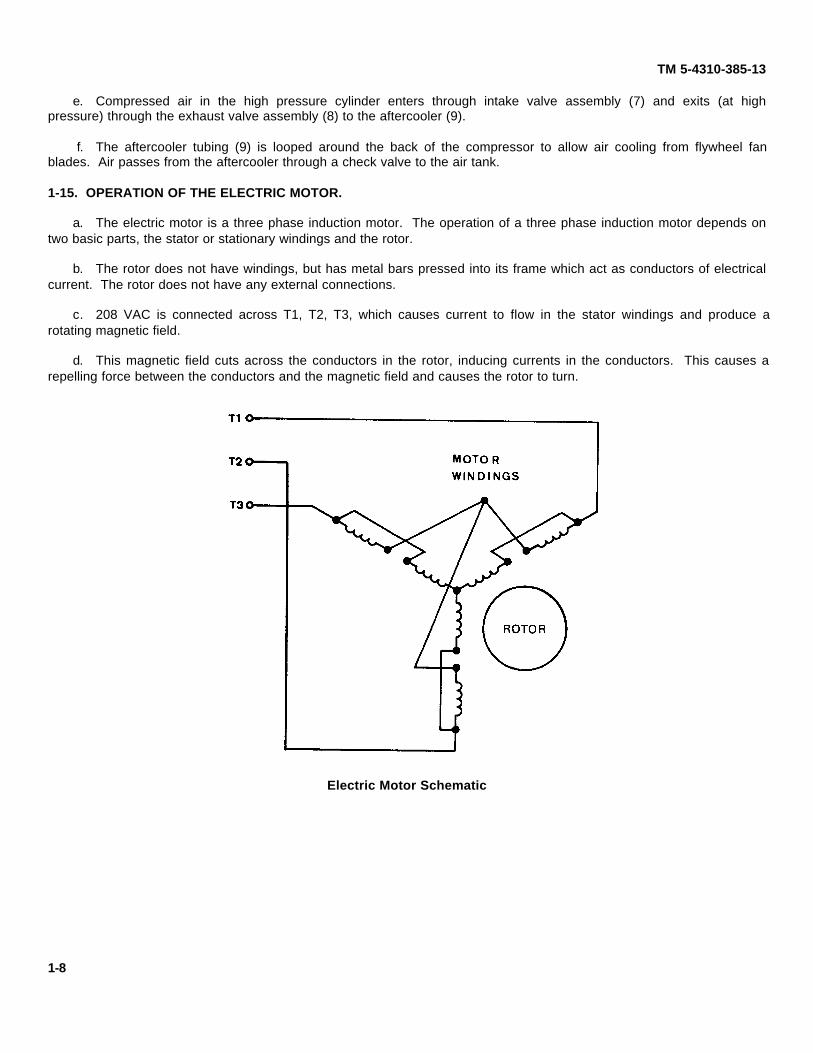
a. The electric motor is a three phase induction motor. The operation of a three phase induction motor depends ontwo basic parts, the stator or stationary windings and the rotor.
b. The rotor does not have windings, but has metal bars pressed into its frame which act as conductors of electricalcurrent. The rotor does not have any external connections.
c. 208 VAC is connected across T1, T2, T3, which causes current to flow in the stator windings and produce arotating magnetic field.
d. This magnetic field cuts across the conductors in the rotor, inducing currents in the conductors. This causes arepelling force between the conductors and the magnetic field and causes the rotor to turn.
Electric Motor Schematic
1-8

TM 5-4310-385-13
1-16. OPERATION OF ELECTRIC MOTOR CONTROLS.
a. The electric motor controls consist of the on/off switch, the reset button, the pressure switch, and the motorstarter. These controls make the operation of the air compressor fully automatic.
NOTE
The overload (OL) in the diagram stands for the melting alloy or heat type devicethat opens when too much current is drawn by the motor such as an OL condition.
b. Power from the main switch comes into the starter at L1, L2, and L3. Connections to the motor are at T1, T2, andT3.
c. Normal operation pressure below 160 psi: when the on/off switch is turned on and the pressure in the tank isbelow 160 psi, the pressure switch contacts will be closed. Current will then go through the coil. The coil then pulls thenormally open contacts E1, E2, and E3 closed. The circuit to the motor is completed and the motor starts.
d. Normal operation pressure above 190 psi: when the pressure goes above 190 psi, the contacts of the pressureswitch open and stop the current through the coil. Contacts E1, E2, and E3 open and the motor stops.
e. Overload Condition: If the motor draws too much current, overload relay OL heats up and the normally closedcontacts in series with the coil open up. This stops the current through the coil and contacts E1, E2, and E3 open. Thisstops the motor and prevents it from burning out. The relay has to be manually reset before the motor can be startedagain. This is accomplished by pushing the reset button which manually closes the overload relay contacts.
Electric Motor Controls Schematic
1-9 (1-10/Blank)
TM 5-4310-385-13
CHAPTER 2. OPERATING INSTRUCTIONS
SECTION I. DESCRIPTION AND USE OF OPERATOR'S CONTROLS AND INDICATORS
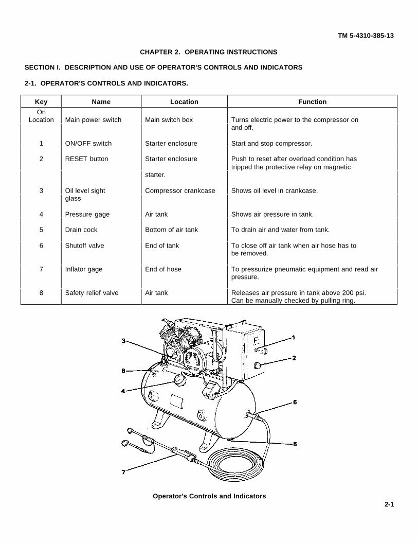
2-1. OPERATOR'S CONTROLS AND INDICATORS.
Key Name Location Function
OnLocation Main power switch Main switch box Turns electric power to the compressor on
and off.
1 ON/OFF switch Starter enclosure Start and stop compressor.
2 RESET button Starter enclosure Push to reset after overload condition hastripped the protective relay on magnetic
starter.
3 Oil level sight Compressor crankcase Shows oil level in crankcase.glass
4 Pressure gage Air tank Shows air pressure in tank.
5 Drain cock Bottom of air tank To drain air and water from tank.
6 Shutoff valve End of tank To close off air tank when air hose has tobe removed.
7 Inflator gage End of hose To pressurize pneumatic equipment and read airpressure.
8 Safety relief valve Air tank Releases air pressure in tank above 200 psi.Can be manually checked by pulling ring.
Operator's Controls and Indicators2-1

TM 5-4310-385-13
SECTION II. OPERATOR'S PREVENTIVE MAINTENANCECHECKS AND SERVICES (PMCS)
2-2. GENERAL. The operators PMCS table lists the inspections and service procedures to properly maintain the aircompressor in good operating condition. Items covered here are appropriate for operator level only. Always keep in mindthe CAUTIONS and WARNINGS before performing checks and services listed in the PMCS table.
2-3. PMCS TABLE FORMAT. The following columns make up the PMCS table.
a. Item No. Each maintenance check is identified by a separate item number. The item column will be used as asource of item numbers for the "TM Number" column on DA Form 2404 Equipment Inspection and MaintenanceWorksheet, in recording results of PMCS.
b. Interval. The interval column of the PMCS table identifies when to perform the service check or maintenance. Adot (•) appears underneath the appropriate column(s) abbreviation:
B - Before OperationD - During OperationA - After OperationW - Weekly
c. Item To Be Inspected/Procedure. This column identifies how to perform the required checks and services.Carefully follow these instructions. If appropriate tools are not available to operator, organizational maintenance shouldperform the work. If your equipment does not perform as required, refer to Chapter 3, Section V. Troubleshooting forpossible problems. Report any malfunctions or failures to organizational maintenance.
d. Equipment Not Ready/Available lf: This column indicates when and why equipment cannot be used aftercompleting the specific PMCS.
NOTE
The terms ready/available and mission capable refer to the same status:Equipment is on hand and is able to perform its combat missions (see DA PAM738-750).
2-4. SPECIAL INSTRUCTIONS.
a. If the equipment must be kept in continuous operation, check and service only those items that can be checkedand serviced without disturbing operation. Make the complete checks and services when the equipment can be shutdown.
b. "Before Operation (B) " checks should be limited to those required for consecutive application by an assignedoperator/crew. Perform "Weekly (W) " as well as "Before Operation (B) " PMCS if:
(1) Compressor has not been operated since the last weekly PMCS, or;
(2) Compressor is being operated for the first time.
c. Leakage definitions for operator/crew PMCS are classified as follows:
Class I Seepage of fluid (as indicated by wetness or discoloration) not great enough to form drops.
Class II Leakage of fluid great enough to form drops but not enough to cause drops to drip from item beingchecked/inspected.
Class III Leakage of fluid great enough to form drops that fall from the item being checked/inspected.
CAUTION
Equipment operation is allowable with minor leakages Class I or II). Consider thefluid capacity in the item/system being checked/inspected. When in doubt, notifyyour supervisor.
When operating with Class I or Class II leaks, continue to check fluid levels asrequired by PMCS table.
Class III leaks should be reported to your supervisor.2-2

B - Before Operation D - During Operation A - After Operation W - WeeklyItemNo.
IntervalItem To Be Inspected. Procedure:
Equipment NotReady/Available If:
B D A W
TM 5-4310-385-13
Table 2-1. Operator's Preventive Maintenance Checks and Services
1 COMPRESSOR DRIVE SYSTEM• a. Inspect belt guard mounting screws (1). Belt guard is damaged
or loose enough to• b. Inspect belt guard mounting bolts (2) to tank. obstruct motion of
pulley, flywheel or belts.• c. Inspect belt guard (3) for damage.
2 COMPRESSOR UNIT
WARNING
Drycleaning solvent, P-D-680, used to clean parts ispotentially dangerous to personnel and property.Avoid repeated and prolonged skin contact by wearingrubber or non-porous gloves when handling thesolvent or material wet with drycleaning solvent. Washhands immediately after exposure with soap and waterand use a lanolin based skin cream to prevent skindrying. Do not use near open flame or excessive heat.Flash point of solvent is 100°° F (38°° C). Do not work withsolvent in a closed room. Be sure there is goodventilation or the solvent vapors will build up in the airand become a poisonous mixture which can causephysical injury or even death.
2-3
B - Before Operation D - During Operation A - After Operation W - WeeklyItemNo.
IntervalItem To Be Inspected. Procedure:
Equipment NotReady/Available If:
B D A W
TM 5-4310-385-13
Table 2-1. Operator's Preventive Maintenance Checks and Services (Continued)
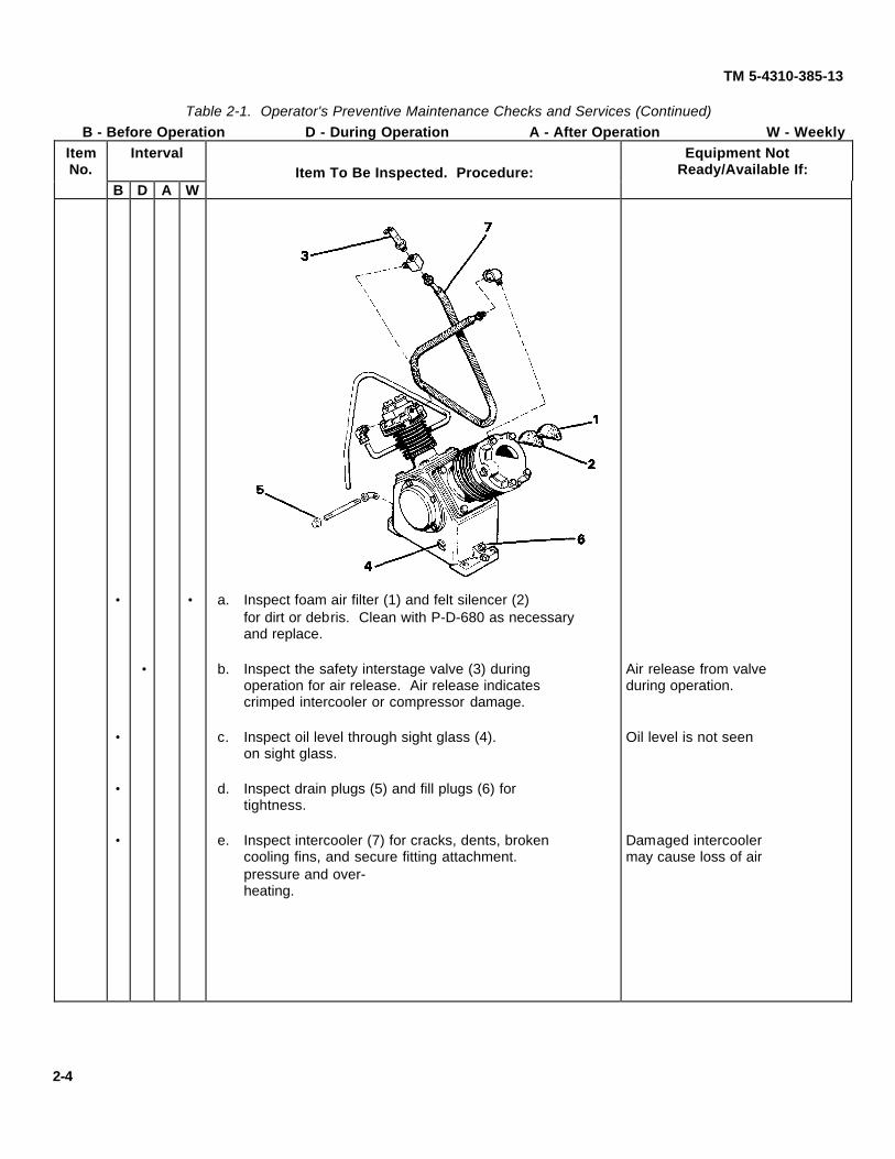
• • a. Inspect foam air filter (1) and felt silencer (2)for dirt or debris. Clean with P-D-680 as necessaryand replace.
• b. Inspect the safety interstage valve (3) during Air release from valveoperation for air release. Air release indicates during operation.crimped intercooler or compressor damage.
• c. Inspect oil level through sight glass (4). Oil level is not seenon sight glass.
• d. Inspect drain plugs (5) and fill plugs (6) fortightness.
• e. Inspect intercooler (7) for cracks, dents, broken Damaged intercoolercooling fins, and secure fitting attachment. may cause loss of airpressure and over-heating.
2-4

B - Before Operation D - During Operation A - After Operation W - WeeklyItemNo.
IntervalItem To Be Inspected. Procedure:
Equipment NotReady/Available If:
B D A W
TM 5-4310-385-13
Table 2-1. Operator's Preventive Maintenance Checks and Services (Continued)
3 ELECTRIC MOTOR• a. Check mounting bolts (1) for tightness. Loose mounting bolts
will not allow proper
• b. Inspect end plates (2) for clogged vents, dirt, or belt tension.debris.
4 AIR RECEIVER SYSTEM
• a. Inspect air tank (1) for any signs of damage. Damaged tank orcomponents allows air
• b. Inspect fittings on air tank for secure attachment: leak.safety valve (2), check valve (3), pressure gauge(4), pressure switch (5), drain cock (6), andglobe valve (7).
2-5
B - Before Operation D - During Operation A - After Operation W - WeeklyItemNo.
IntervalItem To Be Inspected. Procedure:
Equipment NotReady/Available If:
B D A W
TM 5-4310-385-13
Table 2-1. Operator's Preventive Maintenance Checks and Services (Continued)
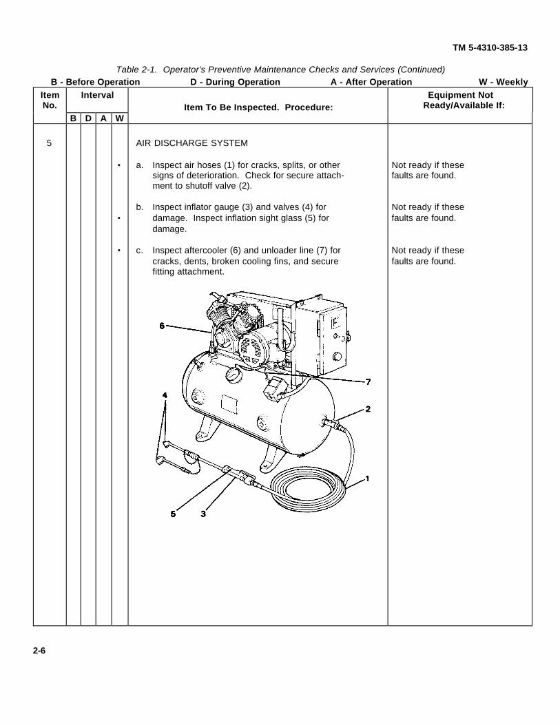
5 AIR DISCHARGE SYSTEM
• a. Inspect air hoses (1) for cracks, splits, or other Not ready if thesesigns of deterioration. Check for secure attach- faults are found.ment to shutoff valve (2).
b. Inspect inflator gauge (3) and valves (4) for Not ready if these• damage. Inspect inflation sight glass (5) for faults are found.
damage.
• c. Inspect aftercooler (6) and unloader line (7) for Not ready if thesecracks, dents, broken cooling fins, and secure faults are found.fitting attachment.
2-6

TM 5-4310-385-13
SECTION III. OPERATION UNDER USUAL CONDITIONS
2-5. PREPARATION FOR USE.
a. The air compressor is shipped completely assembled with all components in place, secured to a bottom skid,within a wood crating enclosure.
b. If compressor is to be used as a portable unit, compressor can be left bolted to bottom skid. Compressor andskid must be placed on firm level ground or flooring to minimize vibration and ensure proper operation.
c. For permanent installation, the manufacturer recommends leaving the compressor bolted to the bottom skid andinstalling the skids to a level surface. The base should be at least 12" from any wall.
CAUTION
If skids are removed, do not eliminate space between the base and a foot bydrawing the foot down. This would stress the tank foot and result in abnormalvibration and possible damage to the tank.
d. If flooring or base is not completely level, shims must be used.
e. Compressor must be located in a clean, well ventilated dry room so compressor receives an adequate supply offresh, clean, cool and dry air. Allow sufficient space around the compressor so that it is accessible from all sides formaintenance.
f. For proper cooling, ensure that no object will obstruct the flow of air through the belt guard to the fan bladedflywheel.
Proper Air Flow
2-7

TM 5-4310-385-13
2-6. ELECTRICAL CONNECTIONS. Connect the motor starter to a 208 VAC 3 phase power source. The source musthave a separate on/off switch for the compressor.
Motor Starter Connections
2-7. INITIAL SERVICE.
CAUTION
The compressor is shipped without oil in the crankcase. Running compressorwithout oil will damage the equipment.
a. Before start-up, remove either fill plug (1 ) and fill the crankcase with 10 oz. (.3 L) of oil. Refer to Table 2-2 forproper oil viscosity. Replace the fill plug.
Oil Fill
2-8

TM 5-4310-385-13
Ambient Oil Type.
Above 90°F (32°C) OE/HDO 40
32-90°F (0-32°C) OE/HDO 30
Below 32°F (0°C) OE/HDO 20
Table 2-2. Proper Oil Viscosity
b. Before start-up, remove the belt guard (2) and turn the compressor flywheel (3) and drive pulley (4) over a fewrevolutions by hand to make sure that there are not any obstructions to shaft rotations. Replace the belt guard (2) andtighten mounting hardware (5).
c. Open the drain cock (6) and drain any moisture from the air tank (7). Close the drain cock (6).
Belt Drive System
2-8. OPERATING PROCEDURE. (Illustration on Page 2-10.)
a. Turn the switch ON at the power source on location.
b. Turn the ON/OFF switch (1) on the face of the starter box ON.
CAUTION
Notify organizational maintenance if the compressor has shut down due tooverload. Overload condition must be removed before compressor is restarted.
c. Turn the shutoff valve (3) counterclockwise to the open position to enable service air to pass from the tank to theair hose and gage (4).
2-9

TM 5-4310-385-13
d. Unwind the air hose (4) from the tank.
e. Attach inflator gage valve (5) to tire or other object requiring air and read pressure with pressure indicator (6).
f. Depress lever (7) to use service air.
g. Turn the ON/OFF switch to the starter box OFF at the end of the work shift.
Operating Procedure
WARNING
Make certain any lifting device used has a capacity equal to the weight being lifted.Failure to observe this precaution could result in injury or death to personnel anddamage to equipment.
2-9. PREPARATION FOR MOVEMENT. The air compressor must be bolted to a bottom skid at all four base legs beforemoving by a fork lift. Slings maybe used to transport a compressor a short distance using a suitable hoist or overheadlifting device. Place slings on outboard ends of tank and center lift hook above unit.
2-10

TM 5-4310-385-13
SECTION IV. OPERATION UNDER UNUSUAL CONDITIONS
2-10. OPERATION IN DUSTY ENVIRONMENT
a. Check and clean air filter (1) and silencer (2) daily to keep it from being clogged.
b. Clean dirt off of electric motor (3), compressor fins (4), intercooler tubing (5), and aftercooler tubing (6) tomaximize air cooling ability.
2-11. OPERATION IN EXTREME HEAT.
a. Make sure that there are no air flow obstructions through the slotted belt guard to the fan bladed flywheel.
b. Clean dirt off of electric motor (3), compressor fins (4), intercooler tubing (5), and aftercooler tubing (6) to maximize air cooling ability.
c. Check air filter (1) and silencer (2) in accordance with the PMCS table schedule (weekly) or sooner (daily).
d. Check for proper oil viscosity. Refer to paragraph 3-2.
Operation Under Unusual Conditions
2-11 (2-12/Blank)
TM 5-4310-385-13
CHAPTER 3. UNIT MAINTENANCE INSTRUCTIONS
SECTION I. LUBRICATION INSTRUCTIONS
NOTE
These lubrication instructions are mandatory.
3-1. GENERAL. Lubrication of the air compressor is Iimited to servicing (changing) the oil in the air compressor unit.
WARNING
The air compressor must be stopped and power switch set to OFF position beforeadding oil to prevent ejection of hot oil.
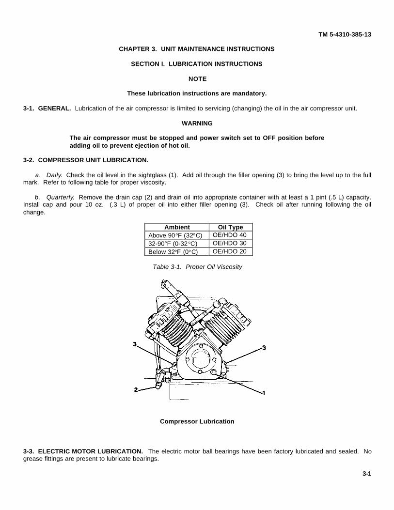
3-2. COMPRESSOR UNIT LUBRICATION.
a. Daily. Check the oil level in the sightglass (1). Add oil through the filler opening (3) to bring the level up to the fullmark. Refer to following table for proper viscosity.
b. Quarterly. Remove the drain cap (2) and drain oil into appropriate container with at least a 1 pint (.5 L) capacity.Install cap and pour 10 oz. (.3 L) of proper oil into either filler opening (3). Check oil after running following the oilchange.
Ambient Oil TypeAbove 90°F (32°C) OE/HDO 4032-90°F (0-32°C) OE/HDO 30Below 32°F (0°C) OE/HDO 20
Table 3-1. Proper Oil Viscosity
Compressor Lubrication
3-3. ELECTRIC MOTOR LUBRICATION. The electric motor ball bearings have been factory lubricated and sealed. Nogrease fittings are present to lubricate bearings.
3-1

TM 5-4310-385-13
SECTION II. REPAIR PARTS, SPECIAL TOOLS, TMDE, AND SUPPORT EQUIPMENT
3-4. COMMON TOOLS AND EQUIPMENT. Refer to Appendix B, Section III Maintenance Allocation Chart, for toolreference usage.
3-5. SPECIAL TOOLS; TEST MEASUREMENT, AND DIAGNOSTIC EQUIPMENT (TMDE) ; AND SUPPORTEQUIPMENT. No special tools are required for the maintenance of this air compressor.
3-6. REPAIR PARTS. Repair parts are listed and illustrated in the Repair Parts and Special Tools List (RPSTL,TM 5-4310-385-23P) covering organizational maintenance for this equipment.
SECTION III. SERVICE UPON RECEIPT OF EQUIPMENT
3-7. CHECKING EQUIPMENT UPON RECEIPT.
CAUTION
The compressor is shipped without oil in the crankcase. Operating compressorwithout oil will destroy the compressor unit.
Service Upon Receipt3-2

TM 5-4310-385-13
a. Before initial start-up, remove either oil fill plug (1) and fill crankcase with 10 oz. (.3 L) of oil of proper viscosity.Refer to paragraph 3-2. Replace fill plug.
b. Check oil level on sightglass (2) before and after first operation.
c. Remove the belt guard (3) and check V-belts (4) for proper tension. Inspect the compressor flywheel and electricmotor drive pulley for secure attachment to shafts.
d. Before start-up, turn the flywheel over a few revolutions by hand to make sure that there aren't any obstructionsanywhere in the unit.
e. Inspect the intercooler tubing (5) and aftercooler tubing (6) for dents, crimps, and secure attachment. Inspectcompressor unloader line (7) to the pressure switch for crimping and secure attachment.
f. Inspect air hose (8) for cuts or cracks or other signs of obvious damage. Inspect the inflator gage (9) for secureattachment to air hose.
g. Inspect all hardware for tightness, particularly for compressor unit and electric motor mountings.
3-8. SITE AND SHELTER REQUIREMENT
a. The compressor was designed for permanent installation in a sheltered environment. Protect the compressorfrom water, excessive dirt and corrosive atmospheres.
b. Compressor must be located in a clean, well ventilated dry place where compressor receives an adequate supplyof fresh, clean, cool and dry air. Allow sufficient space around the compressor so that it is accessible from all sides formaintenance.
c. Locate the compressor away from work areas and areas frequently traveled, preferably outside of themaintenance building. A special noise reduction enclosure may be necessary.
d. Locate the compressor where appropriate three phase, 208 V electrical power with a separate ON/OFF switchmay be installed.
e. For proper cooling, insure that no object will obstruct the flow of air through the slotted belt guard to the fanbladed flywheel.
f. Compressor requires a space approximately 3' x 2' (1 m x .6 m). Locate compressor at least 12" (30.5 cm) fromany wall on a solid, level base.
3-9. INSTALLATION INSTRUCTIONS.
a. Compressor must be installed on a solid, level base. If compressor is to be used as a portable unit, compressorcan be left bolted to bottom skid. Compressor and skid must be placed on firm level ground or flooring to minimizevibration and ensure proper operation.
CAUTIONDo not eliminate space between the base and a foot by drawing the foot down.This would stress the tank foot and result in abnormal vibration and possibledamage to the tank.
b. For permanent installation, bolt the compressor securely and evenly to a level base. If flooring or base is notcompletely level, shims must be used under the feet.
WARNINGPower must be shut off to source line before installation service is performed.Voltages present in this equipment can cause injury or death.
c. Connect the magnetic motor starter to 208 VAC 3 phase line with a separate ON/OFF switch.
d. Before power is applied to unit, check all other wiring terminals in the starter enclosure and pressure switch for asecure fitting.
3-3
TM 5-4310-385-13
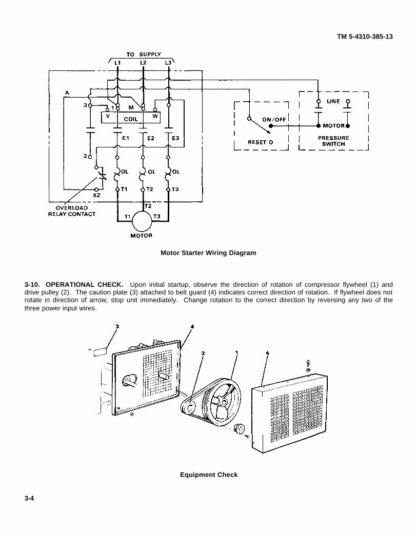
Motor Starter Wiring Diagram
3-10. OPERATIONAL CHECK. Upon initial startup, observe the direction of rotation of compressor flywheel (1) anddrive pulley (2). The caution plate (3) attached to belt guard (4) indicates correct direction of rotation. If flywheel does notrotate in direction of arrow, stop unit immediately. Change rotation to the correct direction by reversing any two of thethree power input wires.
Equipment Check
3-4

Item IntervalNo. W M Q
Item To Be Inspected. Procedures
TM 5-4310-385-13
SECTION IV. UNIT PREVENTIVE MAINTENANCE CHECKS AND SERVICES (PMCS)
3-11. INTRODUCTION. The preventive maintenance checks and services listed in the PMCS table cover procedures tobe performed by unit maintenance personnel.
3-12. PMCS TABLE. Explanation of the columns:
a. Item Number. Checks and services are numbered in sequence. This column shall be used as source of itemnumbers for the TM Number Column on DA Form 2404, Equipment Inspection and Maintenance Worksheet, in recordingresults of PMCS.
b. Interval. The amount of time, in calendar days, between scheduled checks and services.
(1) W - Weekly(2) M - Monthly(3) Q - Quarterly
c. Item To Be Inspected. This column gives the name of the item to be inspected or serviced.
d. Procedures. This column lists inspection procedures.
Table 3-2. Unit Preventive Maintenance Checks and Services.
W - Weekly M - Monthly Q - Quarterly
1 MOTOR STARTER• a. Check starter enclosure mounting bolts and nuts (1) for tightness.
• b. Turn main power off and ON/OFF switch off. Check all wireconnections at terminal screws (2) for secure attachment.
• c. With power on and ON/OFF switch on, observe motor starter whilemachine cycles. Magnetic contact arm (3) shouldopen and close (contact base) with operation ofpressure switch.
3-5

Item IntervalNo. W M Q
Item To Be Inspected. Procedures
TM 5-4310-385-13
Table 3-2. Unit Preventive Maintenance Checks and Services (Continued).
W - Weekly M - Monthly Q - Quarterly
2 PRESSURE SWITCH• a. Inspect pressure switch fitting (1) at tank for air leaks.
• b. Turn power off and ON/OFF switch off. Check wireconnections at screw terminals (2) for secure attachment.
• c. With power on and ON/OFF switch on, check operationof pressure switch (3) by observing pressure gauge while depressinginflator gauge lever. Pressure switch should engagestarter at 160 psi and stop starter at 190 psi.
3 COMPRESSOR DRIVE• a. Inspect belt guard mounting screws (1). Remove screws and
belt guard (2).• b. Inspect belt guard mounting bolts (3) to tank saddle.• c. Inspect V-belts (4) for cracks or signs of wear.
• d. Inspect drive pulley (5) for secure attachment to motor shaft. Checkkey and bushing capscrews (6) for tightness.
3-6

Item IntervalNo. W M Q
Item To Be Inspected. Procedures
TM 5-4310-385-13
Table 3-2. Unit Preventive Maintenance Checks and Services (Continued).
W - Weekly M - Monthly Q - Quarterly
4 COMPRESSOR ASSEMBLY• a. Check mounting bolts (1) for tightness.
• b. Check eight cylinder mounting bolts (2) to crankcase.• c. Check eight cylinder head mounting bolts (3) for tightness.• d. Check oil level through sight glass (4). Add oil through either fill
plug opening (5) until oil reaches full mark on glass.• e. Remove belt guard and inspect flywheel (6) for secure
attachment to shaft.
3-7

TM 5-4310-385-13
SECTION V. UNIT TROUBLESHOOTING
3-13. GENERAL. Troubleshooting at the unit maintenance level requires location of any trouble as quickly as possible.Once trouble is located, repair or replace the part if authorized to do so or determine if a higher category of maintenanceis required. Repairs by unit maintenance are limited by tools, test equipment and replacement parts allocated to thatlevel.
3-14. ELECTRICAL SYSTEM.
a. Problems in the motor control circuitry will usually cause the motor to stop running. Note that there has to becurrent through the coil for contacts E1, E2 and E3 to close. This means that the motor won't run if the coil circuit is badeven though the rest of the circuit is good.
b. Overload conditions will cause the overload relay contact to open. Overloading may be caused by shorts in themotor or by a blockage in the compressor. Overload conditions must be removed before the compressor can be put backin operation. Otherwise, the relay will just open up again.
c. Once overload conditions have been eliminated, the RESET button on the motor starter box must be pushed torestart the compressor.
d. The electric motor is made up of electrical and mechanical components. The main mechanical componentswhich may fail are the bearings.
e. Other malfunctions are usually due to problems with the electrical components.
3-15. COMPRESSOR UNIT.
a. The compressor drive is a fairly simple system. The main problems are improper belt tension, bad alignment andloose parts.
b. The intake and exhaust valves are the most critical parts of the compressor. Loss of pumping efficiency can mostoften be traced back to the valves.
c. Problems with not getting enough air are not always caused by the compressor. Leaky fittings or an improperlyadjusted pressure switch may also be at fault.
3-16. TROUBLESHOOTING TABLE. The following columns are used in the Troubleshooting Table.
a. Malfunction. Malfunctions listed are the ones most likely to happen. Not all possible malfunctions can beforeseen and listed.
b. Test or Inspection. Tests or inspections are listed to help you find the cause of the malfunction. The malfunctionswhich are most likely to occur are listed first. The malfunctions least likely to occur are listed last.
c. Corrective Action. Corrective actions are listed to help eliminate the malfunction. Where the corrective action istoo complicated to be listed in full detail, the paragraph number of the maintenance procedure is given in parentheses.
3-8
TM 5-4310-385-13Table 3-3. Troubleshooting
MalfunctionTest or Inspection
Corrective ActionELECTRICAL SYSTEM
1. ELECTRIC MOTOR WON'T START
Step 1. Check to see that main power and ON/OFF switch is ON.
Turn power ON.
Step 2. Press RESET button on motor starter box.
Reset button will start motor only if relay was tripped by momentary overload.
Step 3. Check pressure switch connections for tightness.
Tighten connections as necessary.
Step 4. Check if pressure switch contacts are open at pressures below 160 psi.
Replace switch if contacts do not close. Refer to paragraph 3-21.
Step 5. Check motor starter connections for looseness.
Tighten connections as necessary. Refer to paragraph 3-20.
Step 6. Check motor controls for faulty wiring.
Wire controls correctly. Refer to paragraph 3-20.
Step 7. Check for bad motor control coil. Check for continuity between terminals of the coil.
Replace coil. Refer to paragraph 3-20.
Step 8. Check for bad motor control contactor. Check for continuity across each pair of terminals.
Replace contactor. Refer to paragraph 3-20.
Step 9. Check for burned motor control contacts.
Replace contactor. Refer to paragraph 3-20.
2. MOTOR HUMS BUT WON'T RUN.
Step 1. Check all three phases for power using voltmeter.
If voltage is incorrect, provide correct voltage.
Step 2. Check for open or short circuited motor windings. Refer to paragraph 3-33.
If windings are defective, notify direct support.
3. LOW AIR PRESSURE.
Step 1. Check to see if compressor cuts out at pressure below 190 psi.
Adjust pressure switch. Refer to paragraph 3-21.3-9

TM 5-4310-385-13Table 3-3. Troubleshooting (Continued)
MalfunctionTest or Inspection
Corrective Action4. IF OVERLOAD KICKS OUT REPEATEDLY.
Step 1. Check for short circuits between windings T1, T2, T3 and motor frame. Refer to paragraph 3-33.
If windings are shorted, notify direct support.
Step 2. Check for restriction of air flow between cylinder heads (intercooler), or from compressor to tank(aftercooler).
Replace damaged compressor tubing. Refer to paragraphs 3-31 and 3-44.
Step 3. Check for overloading of compressor.
Reduce air pressure to within tolerance.
COMPRESSOR UNIT
5. COMPRESSOR DOES NOT PUT OUT ENOUGH AIR.
Step 1. Check for dirty or clogged intake filters.
Clean or replace as necessary.
Step 2. Check if V-belts are loose.
Tighten belts. Refer to paragraph 3-24.
6. BELTS WEAR TOO FAST.
Step 1. Check if V-belts are loose.
Tighten belts. Refer to paragraph 3-24.
Step 2. Check if drive pulley and flywheel are out of alignment.
Align pulley and flywheel. Refer to paragraph 3-25.
7. COMPRESSOR OIL LOSS.
Step 1. If unit is new, oil consumption may be high until valve assemblies seat.Wait for valves to seat, then recheck oil consumption.Notify direct support if oil consumption continues to be high.
8. SLOW PUMPING OR INSUFFICIENT PRESSURE.
Step 1. Check for leaks in air lines and fittings.Tighten fittings or replace leaking parts. Refer to paragraph 3-34.
Step 2. Check for exceeding compressor capacity.Reduce air usage.
Step 3. Check for wrong adjustment of pressure switch.Adjust pressure switch to cut in at 160 psi and to cut out at 190 psi. Refer to paragraph 3-21.
Step 4. Check for broken valve assembles.Replace damaged valve. Refer to paragraph 3-32.
3-10
TM 5-4310-385-13
Table 3-3. Troubleshooting (Continued)
MalfunctionTest or Inspection
Corrective Action
9. COMPRESSOR OVERHEATS.
Step 1. Check if pump is low on oil.
Add oil to bring level up to full mark on sight glass. Refer to paragraph 3-2.
Step 2. Check for dirt in intercooler, aftercooler or cylinder fins.Remove dirt.
Step 3. Compressor is getting poor ventilation.
Clear obstructions from around the compressor. Ensure proper air flow through belt guard.
Step 4. Check for leaky cylinder gaskets.
Replace gaskets if defective. Refer to paragraph 3-32.
Step 5. Check for broken valve.
Replace valve if damaged. Refer to paragraph 3-32.
Step 6. Check if compressor is running backwards (clockwise as you face the flywheel).
Rewire motor so it runs counterclockwise. Refer to paragraph 3-33.
10. NOISY COMPRESSOR OPERATION.
Step 1. Check for loose mounting bolts, drive pulley or flywheel.
Tighten loose components. Refer to paragraph 3-27, 3-25 or 3-30.
Step 2. Check for foreign matter such as carbon, metal chips, etc. in cylinder.
Remove cylinder head and valve plates and clean cylinder. Refer to paragraph 3-32.
Step 3. Listen for loose or damaged internal compressor parts (connecting rods, crankshaft, etc.).
Refer to direct support for inspection and repair if internal compressor damage is suspected.
3-11

TM 5-4310-385-13
SECTION VI. UNIT MAINTENANCE PROCEDURES
3-17. GENERAL. This section contains removal, disassembly, inspection, cleaning, repair, assembly and installation ofcompressor components listed in Appendix B, Section III, Maintenance Allocation Chart. Paragraph references are listedbelow for each grouping for locating component repair instructions.
a. Paragraph 3-18, Motor Controls Group: Motor Starter Enclosure, Motor Starter, Pressure Switch.
b. Paragraph 3-22, Compressor Drive Group: Belt Guard, V-Belts, Drive Pulley.
c. Paragraph 3-26, Compressor Assembly Compressor Unit, Safety Interstage Valve, Oil Filler and Drain Plugs,Flywheel, Intercooler, Intake and Exhaust Valves.
d. Paragraph 3-33, Electric Motor.
e. Paragraph 3-34, Air Receiver System: Safety Valve, Check Valve, Pressure Gauge, Drain Cock, Shutoff Valve,and Air Tank.
f. Paragraph 3-41, Air Discharge System: Air Hoses, Inflator Gage, Tube Assemblies.
3-12

TM 5-4310-385-13
3-18. MOTOR CONTROLS GROUP.
3-19. MOTOR STARTER ENCLOSURE. This task covers:
a. Initial Setup. b. Removal. c. Installation.
INITIAL SETUP.
a. Tools. General Mechanic Automotive Tool Kit. T1 5180-00-177-7033.
b. Equipment Condition. Main power disconnected; Compressor unit OFF.
c. General Safety Requirements.
WARNING
•• Observe all Warnings and Cautions.
•• Never wear loose Clothing or jewelry while inspecting or servicing equipment.
•• Beware of rotating shafts, pulleys and fans which could entrap personnel andcause serious injury.
Motor Starter Enclosure
3-13

TM 5-4310-385-13
REMOVAL.
WARNING
Disconnect main power source and turn compressor unit OFF before performingmaintenance procedures. Voltages present in this equipment can cause injury ordeath.
a. Open cover (1) by turning key (2) and depressing latch on enclosure (3).b. Disconnect and tag all wires (7) from starter assembly.c. Loosen three screws (4) from base plate (5) and raise base plate up.d. Remove starter assembly (6) from enclosure (3).e. Remove conduit locknuts (8) and pull conduits and wires (9) from enclosure.f. Remove bolts, nuts, and washers (10) securing enclosure to saddle frame (11 ).
g. Remove nut (12), ON/OFF plate (13) and toggle switch (14) from enclosure cover.
INSTALLATION.
a. Position toggle switch (14) and ON/OFF plate (13) on enclosure cover and secure with nut (12).b. Install bolts, nuts, and washers (10) securing enclosure (3) to frame (11).c. Push power source conduit and motor wires (9) through holes in enclosure and secure with locknuts (8).d. Place starter assembly (6) into enclosure far enough to connect wires (9).e. Connect all wires (9) to starter assembly (6) as tagged.f. Install screws and washers (4) that secure starter assembly base plate (5) to enclosure.
CAUTION
Recheck all wiring connections before turning main power on. If not sure, refer towiring diagram.
g. Close enclosure door.h. Reconnect main power.
3-14

TM 5-4310-385-13
3-20. MOTOR STARTER. This task covers:a. Initial Setup. c. Cleaning and Inspection.b. Disassembly. d. Reassembly.
INITIAL SETUP
a. Tools. General Mechanic Auto; T1 5180-00-177-7033.b. Materials/Parts. Compressed Air; Wiping rag.c. Equipment Condition. Main power disconnected; Compressor Unit OFF; Motor Starter Removed
(paragraph 3-19).d. General Safety Requirements.
WARNING
•• Observe all Warnings and Cautions.•• Never wear loose Clothing or jewelry while inspecting or servicing equipment.•• Beware of rotating shafts, pulleys and fans which could entrap personnel and
cause serious injury.
DISASSEMBLY
WARNINGBe sure main power is disconnected and tagged before doing any work onelectrical systems. Voltages present in this equipment can cause injury or death.
a. Tag and remove wires from coil terminal W (1) and terminal screw L2 (2).
b. Remove starter assembly from enclosure. Refer to paragraph 3-19.
c. Remove screws (3) that retain cover (4). Remove cover.
3-15

TM 5-4310-385-13
d. Remove two screws (5) that secure contact board (6) to base plate (7).
e. Separate coil (8) from base plate (7) by pulling back on clips (9).
f. Remove magnet (10) from coil (8).
g. Holding starter in left hand, press on crossarm as far as it will go while you grasp the clip (11) and lift and slide thearmature (12) from coil (8).
h. Tag and remove relay wires (13) at X1 and X2.
i. Loosen three setscrews (14) and remove overload relay (15) from contact board (6).
NOTE
Relay(15) is not repairable and should not be disassembled. Replace entire relayas necessary.
j. Remove cross arm assembly (16, 17, 18) and springs (19) from board (6).
CLEANING AND INSPECTION.
WARNINGClean motor starter components with compressed air no greater than 30 psi. Eyeprotective equipment must be worn when cleaning with compressed air.
a. Use compressed air no greater than 30 psi to blow out dirt from all motor starter components. Wipe withclean rag.
b. Inspect all non-metal components for cracks. Replace as necessary.
NOTEContacts will discolor and pit in use.
c. Inspect contacts (17) for excessive pitting or burning. Replace as necessary.d. Inspect overload relay (15) for cracks or melted overload coils. Replace entire relay as necessary.
REASSEMBLY.
a. Install contacts (17) on crossarm (16).b. Assemble crossarm (16), crossarm base (18), and springs (19) to contact board (6).c. Install spring clip (11) and armature (12).d. Install overload relay (15) to contact board (6). Tighten setscrews (14).e. Connect two relay wires (13) at X1 and X2.f. Slide magnet (10) into coil (8).
g. Install coil (8) into base plate (7). Make sure retaining clips (9) are engaged.h. Position contact board (6) onto base plate (7) and secure with two screws (5).i. Install cover (4) and tighten screws (3).j. Connect wires to coil terminal W (1) and terminal screw (2).
k. Connect wires to overload relay terminals (13).I. Install starter assembly to enclosure. Refer to paragraph 3-19.
m. Double check wiring for correct installation and make sure all terminal screws are tight.
3-16

TM 5-4310-385-13
3-21. PRESSURE SWITCH. This task covers:
a. Initial Setup. c. Inspection. e. Installation.b. Removal. d. Cleaning. f. Adjustment.
INITIAL SETUP.
a. Tools. General Mechanic Automotive Tool Kit; T1 5180-00-177-7033.b. Materials/Parts. Compressed Air; Brush; Anti-Seize Tape.c. Equipment Condition. Main power disconnected; Compressor unit OFF; Air in tank discharged.d. General Safety Requirements.
WARNING
•• Observe all Warnings and Cautions.•• Never wear loose Clothing or jewelry while inspecting or servicing equipment.•• Beware of rotating shafts, pulleys and fans which could entrap personnel and
cause serious injury.
Pressure Switch
INSPECTION.
CAUTIONUse soap solution to check for air leaks at tank fittings only.
a. With air pressure present in tank, inspect the pressure switch for air leaks using a soap and water solution.b. Check for air discharge from unloader valve (7) upon compressor shutdown.c. Inspect the switch contacts for burning or pitting. Replace the pressure switch if contacts are bad.
3-17

TM 5-4310-385-13
REMOVAL.
WARNINGBe sure main power is disconnected before doing any work on electrical systems.Voltages present in this equipment can cause injury or death.
a. Disconnect the main power and turn the ON/OFF switch OFF.
WARNING
Air in tank must be discharged before removal of pressure switch to preventserious injury.
b. Open the drain cock on bottom of tank to discharge all air pressure. Close drain cock.
c. Loosen screw (1) and remove cover (2).
d. Tag and label motor and power wires (3).
e. Loosen terminal screws (4) and disconnect wires from switch terminals.
f. Remove conduit locknuts (5) and remove conduit (6).
g. Remove unloader line (7) at fitting.
h. Unscrew pressure switch by hand from pipe fitting (8).
CLEANING.
WARNINGClean pressure switch with compressed air no greater than 30 psi. Eye protectiveequipment must be worn when cleaning with compressed air.
a. Remove loose dirt from inside of pressure switch with soft brush and compressed air.
INSTALLATION.
WARNING
Be sure main power is disconnected before doing any work on electrical systems.Voltages present in this equipment can cause injury or death.
a. Install the pressure switch onto pipe fitting (8).b. Install the unloader line (7) at the fitting.c. Remove the cover (2).d. Attach the conduit (6) with locknuts (5).e. Attach wires (3) to switch terminals as tagged and tighten screws (4).f. Replace cover (2) and tighten screw (1).
g. Connect the main power and turn the ON/OFF switch ON.h. Compressor should start up if switch is properly connected.
3-18

TM 5-4310-385-13
Pressure Switch Adjustment
ADJUSTMENT
WARNING
To prevent injury, be sure the compressor unit is free of objects or loose Clothing,as it will be running during part of the adjustment procedure.
a. Depress lever on inflator gage while watching pressure gage. Compressor should kick-on at approximately 160psi (cut-in).
b. Release lever and allow pressure to build in air tank while watching pressure gage. Compressor should kick off atapproximately 190 psi (cut-out).
c. if either cut-in or cut-out pressure is incorrect (± 5 psi), proceed to step d.
d. Disconnect main power and turn OFF/ON switch OFF.
e. Loosen screw (1) and remove pressure switch cover (2).
f. Turn pressure adjusting screw (3) and differential adjusting screw (4) according to the following:
Pressure Adjustment Procedure
g. Recheck cut-in and cut-out pressures until adjustment is within limits.h. Install pressure switch cover (2) and tighten screw (1).i. Connect main power supply.
3-19
TM 5-4310-385-13
3-22. COMPRESSOR DRIVE GROUP
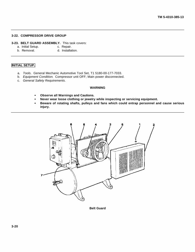
3-23. BELT GUARD ASSEMBLY. This task covers:a. Initial Setup. c. Repair.b. Removal. d. Installation.
INITIAL SETUP.
a. Tools. General Mechanic Automotive Tool Set, T1 5180-00-177-7033.b. Equipment Condition. Compressor unit OFF; Main power disconnected.c. General Safety Requirements.
WARNING
•• Observe all Warnings and Cautions.•• Never wear loose clothing or jewelry while inspecting or servicing equipment.•• Beware of rotating shafts, pulleys and fans which could entrap personnel and cause serious
injury.
Belt Guard
3-20
TM 5-4310-385-13
REMOVAL.
WARNING
Disconnect main power source and turn compressor unit OFF before performingmaintenance procedures.
a. Disconnect the main power and turn the power switch OFF.b. Remove the screws (1) that retain the belt guard (2) to the base plate (3).c. If base plate (3) must be removed, refer to paragraph 3-25 for drive pulley(4) removal and paragraph 3-30 for
flywheel (5) removal.d. Remove the mounting bolts, nuts, and lockwashers (6) securing base plate (3) to tank saddle (7).e. Remove the base plate (3).
REPAIR.
a. Inspect the belt guard for missing rivnuts (8). Replace with metal screws as necessary.b. Inspect the belt guard (2) and base plate (3) for damage. Straighten as necessary to ensure correct fit and
alignment.
INSTALLATION.
a. Disconnect the main power and turn the power switch OFF.b. Install the base plate (3) and mounting hardware (6) if removed.c. Refer to paragraph 3-25 for drive pulley (4) installation and paragraph 3-30 for flywheel (5) installation.d. Install belt guard (2) and retaining screws (1).e. Reconnect the main power source and turn compressor on.
3-21

TM 5-4310-385-13
3-24. V-BELT. This task covers:
a. Initial Setup b. Removal c. Installation. d. Adjustment
INITIAL SETUP.
a. Tools. General Automatic Tool Set, T1 5180-00-177-7033.b. Equipment Condition. Main power disconnected; Compressor unit OFF, Belt guard removed (paragraph 3-23).c. General Safety Requirements.
WARNING•• Observe all Warnings and Cautions.•• Never wear loose Clothing or jewelry while inspecting or servicing equipment.•• Beware of rotating shafts, pulleys and fans which could entrap personnel and
cause serious injury.
V-Belt
REMOVAL.
WARNING
Disconnect main power source and turn compressor unit off before performingmaintenance procedures.
a. Disconnect the main power source and turn compressor switch OFF.b. Loosen the electric motor mounting bolts (1) and slide motor towards compressor flywheel to relieve belt
tension.
CAUTIONBelts may be cut or damaged if removed under tension.
c. Remove two V-belts (2).
3-22

TM 5-4310-385-13
INSTALLATION.
a. Disconnect the main power source and turn the power switch OFF.b. Be sure the electric motor mounting bolts (1) are loose and motor is moved toward compressor flywheel.
NOTEV-belts must be replaced as a set.
c. Place V-belts (2) in position over compressor flywheel (3) and drive pulley (4).d. Adjust belt tension. Refer to next paragraph.
V-Belt Adjustment
ADJUSTMENT.
WARNINGDisconnect main power source and turn compressor unit off before performingmaintenance procedures.
a. Disconnect main power supply and turn power switch OFF.b. Remove belt guard. Refer to paragraph 3-23.c. Loosen the electric motor mounting bolts (1) and slide motor away from compressor to tighten belt tension or
towards compressor to loosen.
CAUTIONToo little belt tension causes belts to overheat and wear out prematurely. Toomuch tension causes bearing wear in motor and compressor.
d. Tighten mounting bolts (1) when proper belt tension is achieved. Belt should move 1/2" when pushed halfwaybetween pulley (4) and flywheel (3).
e. Install belt guard. Refer to paragraph 3-23.
3-23
TM 5-4310-385-13
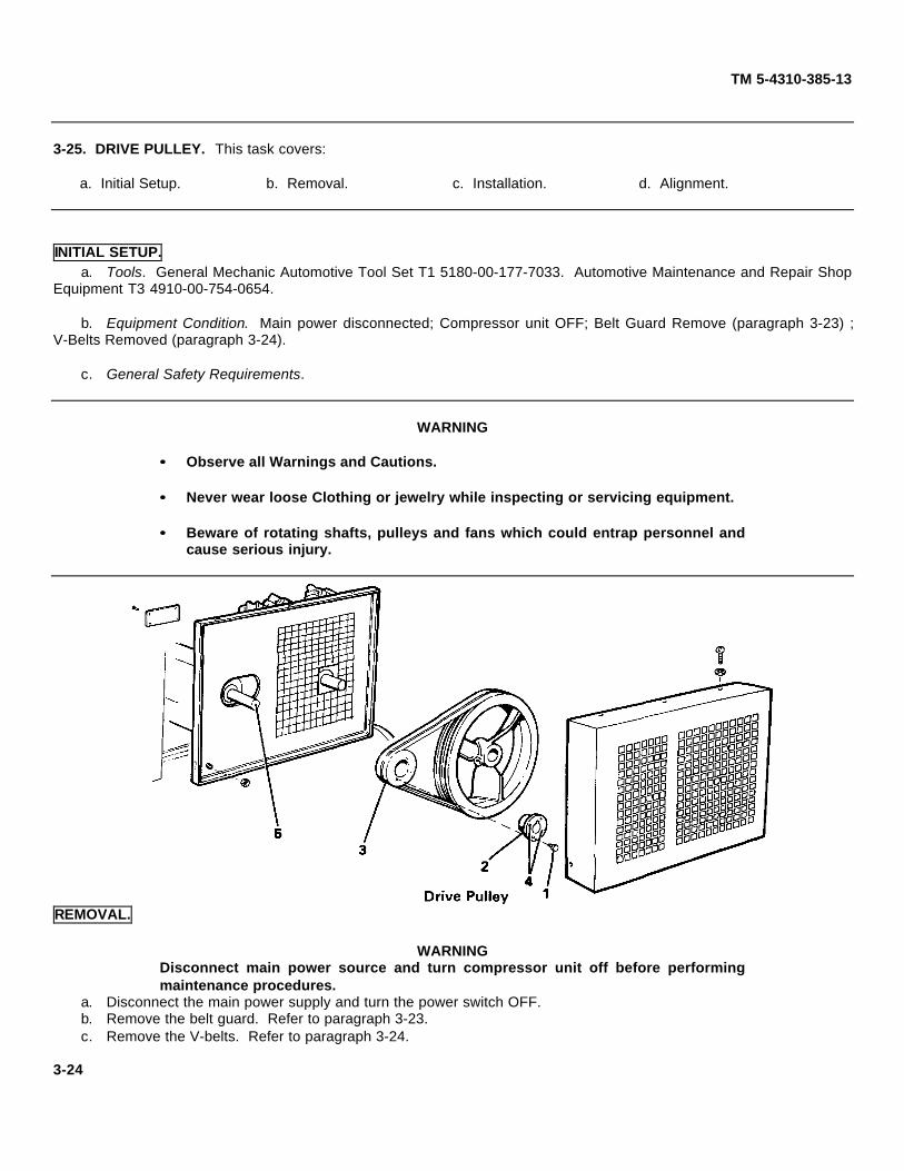
3-25. DRIVE PULLEY. This task covers:
a. Initial Setup. b. Removal. c. Installation. d. Alignment.
INITIAL SETUP. a. Tools. General Mechanic Automotive Tool Set T1 5180-00-177-7033. Automotive Maintenance and Repair Shop
Equipment T3 4910-00-754-0654.
b. Equipment Condition. Main power disconnected; Compressor unit OFF; Belt Guard Remove (paragraph 3-23) ;V-Belts Removed (paragraph 3-24).
c. General Safety Requirements.
WARNING
•• Observe all Warnings and Cautions.
•• Never wear loose Clothing or jewelry while inspecting or servicing equipment.
•• Beware of rotating shafts, pulleys and fans which could entrap personnel andcause serious injury.
REMOVAL.
WARNINGDisconnect main power source and turn compressor unit off before performingmaintenance procedures.
a. Disconnect the main power supply and turn the power switch OFF.b. Remove the belt guard. Refer to paragraph 3-23.c. Remove the V-belts. Refer to paragraph 3-24.
3-24

TM 5-4310-385-13
d. Remove the capscrews (1) securing the bushing (2) to the pulley (3).e. Thread capscrews (1) into jacking holes (4) and tighten evenly until bushing and pulley separate.
NOTEApply a thin coat of oil to shaft to ease bushing removal.
f. Remove bushing and pulley from shaft.g. Remove key (5) from shaft.
INSTALLATION.
a. Install key (5) in shaft keyway.b. Place pulley (3) into position with aligning key.c. Place bushing (2) on shaft and align unthreaded holes in bushing with threaded holes in pulley.d. Thread capscrews (1) into pulley (3).e. Before tightening capscrews, align drive pulley grooves with flywheel grooves. Refer to next paragraph.f. Tighten capscrews evenly until bushing is seated and pulley is secure.
Drive Pulley Alignment
ALIGNMENT.
a. Place straightedge (1) across compressor flywheel (2) and drive pulley (3).
b. Measure distance from straightedge to flywheel outer belt groove.
c. Loosen capscrews on drive pulley and move drive pulley on motor shaft so that pulley outer belt groove is samedistance from straightedge.
d. Tighten capscrews (4) after alignment.
3-25

TM 5-4310-385-13
3-26. COMPRESSOR ASSEMBLY GROUP.3-27. COMPRESSOR UNIT. This task covers:
a. Initial Setup. c. Removal.b. Inspection. d. Installation.
INITIAL SETUP.
a. Tools. General Mechanic Automotive Tool Set, T1 5180-00-177-7033.
b. Materials/Parts. 10 oz. (.3 L) Engine Lubricating Oil, OE-30 or equivalent.
c. Equipment Condition. Main power disconnected, Compressor unit OFF, Tank pressure discharged, Belt guardremoved (paragraph 3-23), V-belts removed (paragraph 3-24), Flywheel removed (paragraph 3-28).
d. General Safety Requirements.
WARNING
•• Observe all Warnings and Cautions.•• Never wear loose Clothing or jewelry while inspecting or servicing equipment.•• Beware of rotating shafts, pulleys and fans which could entrap personnel and
cause serious injury.
Compressor Unit3-26

TM 5-4310-385-13
INSPECTION.
a. Inspect the cylinder head fittings (1) for cracks and secure attachment.
b. Inspect the cylinder heads (2) and cylinders (3) for cracks and broken cooling fins. Notify intermediate directsupport if damaged.
c. Inspect the crankcase (4) for cracks. Notify direct support if damaged.
d. Inspect the air cleaner filter (13) and felt silencer(14) for dirt and debris. Clean with P-D-680 as necessary. Ifdistorted or damaged, replace.
REMOVAL.
WARNINGDisconnect main power and turn compressor unit off before performingmaintenance procedures.
a. Turn the compressor power switch OFF.
b. Open drain cock at bottom of tank to release air pressure. Close drain cock.
c. Remove belt guard. Refer to paragraph 3-23.
d. Remove V-belts. Refer to paragraph 3-24.
e. Remove flywheel. Refer to paragraph 3-30.
f. Remove oil drain cap (5) and drain oil into an appropriate container (at least 1 pint (.5 L) capacity). Replace oildrain cap.
g. Remove intercooler (6) at cylinder head fittings (1).
h. Remove aftercooler (7) at cylinder head fitting (1) and check valve fitting (8).
i. Remove mounting bolts, washers, and nuts (9) securing compressor to tank saddle.
j. Lift compressor unit (10) off base.
INSTALLATION.
a. Position compressor unit (10) on base.
b. Install mounting bolts, washers, and nuts (9) to secure compressor to tank saddle.
c. Install aftercooler (7) at cylinder head fitting (1) and check valve fitting (8).
d. Install intercooler (6) at cylinder head fittings (1).
e. Install flywheel. Refer to paragraph 3-30.
f. Install V-belts. Refer to paragraph 3-24.
g. Check belt tension and pulley alignment. Compressor should turn freely by hand. If not, refer to paragraph 3-24for belt adjustment and paragraph 3-25 for pulley alignment.
h. Install belt guard. Refer to paragraph 3-23.
i. Remove oil filler plug (11) and add 10 oz. (.3 L) if oil has been drained. Check oil level in sight glass (12).
j. Reconnect main power.
3-27

TM 5-4310-385-13
3-28. SAFETY INTERSTAGE VALVE. This task covers:
a. Inspection. b. Removal. c. Installation
INITIAL SETUP.
a. Tools. General Automotive Tool Set, T1-5180-00-177-7033.b. Materials/Parts. Soap Solution. Anti-seize tape.c. General Safety Requirements.
WARNING
•• Observe all Warnings and Cautions.•• Never wear loose Clothing or jewelry while inspecting or servicing equipment.•• Beware of rotating shafts, pulleys and fans which could entrap personnel and
cause serious injury.
INSPECTION.
a. Using a soap solution, check for release of air from the brass fitting (1) or safety valve (2) itself.b. If leakage was detected from the valve, valve may be defective or valve may have blown due to overpressure in
intercooler. Check for crimped intercooler tubing (3), replace valve, and restart compressor. If valve blows again, refercompressor to intermediate direct support maintenance.
c. If air leaks between brass fitting (1) and valve (2), tighten valve.
REMOVAL.
WARNINGDisconnect main power and turn compressor unit off before performingmaintenance procedures.
a. Remove safety valve (2) from brass fitting (1).
INSTALLATION.
a. Coat threads of valve (2) with anti-seize tape.b. Install valve (2) to brass fitting (1).
3-28

TM 5-4310-385-13
3-29. OIL FILTER, DRAIN AND PLUGS. This task covers:
a. Initial Setup. b. Removal. c. Installation.
INITIAL SETUP.
a. Tool. General Automotive Tool Kit T1-5180-00-170-7033.b. Material/Parts Compressor. Oil, OE-30 or equivalent.c. Equipment Condition. Main power disconnected, Compressor unit OFF.d. General Safety Requirements.
WARNING
•• Observe all Warnings and Cautions.•• Never wear loose Clothing or jewelry while inspecting or servicing equipment.•• Beware of rotating shafts, pulleys and fans which could entrap personnel and
cause serious injury.
Oil Fill and Drain Plugs
3-29

TM 5-4310-385-13
REMOVAL.
WARNINGDisconnect main power and turn compressor unit off before performingmaintenance procedures.
a. Remove oil drain cap (1) and drain oil into a suitable container (minimum 10 oz., .3 L).
b. Remove drain pipe (2) from elbow (3).
c. Remove elbow (3).
d. Remove drain plug (4) on opposite side.
e. Remove fill plugs (5).
INSTALLATION.
a. Install pipe elbow (3) to compressor crankcase.
b. Install drain pipe (2) and drain cap (1).
c. Install drain plug (4) on opposite side.
d. Fill crankcase with 10 oz. (.3 L) of OE-30 oil (or equivalent). Check level on sight glass.
e. Replace fill plugs (5).
f. Connect main power and perform operational check.
3-30

TM 5-4310-385-13
3-30. FLYWHEEL. This task covers:
a. Initial Setup. c. Removal.b. Inspection. d. Installation.
INITIAL SETUP.
a. Tools. General Mechanic Automotive Tool Set, T1 5180-00-177-7033; Automotive Maintenance and Repair ShopEquipment, T3 4910-00-754-0654.
b. Materials/Parts. Engine Lubricating Oil OE-30 or equivalent.
c. Equipment Condition. Main power disconnected, Compressor unit OFF, Belt guard removed (paragraph 3-23), V-belts removed (paragraph 3-24).
d. General Safety Requirements.
WARNING
•• Observe all Warnings and Cautions.
•• Never wear loose Clothing or jewelry while inspecting or servicing equipment.
•• Beware of rotating shafts, pulleys and fans which could entrap personnel andcause serious injury.
INSPECTION.
WARNINGDisconnect main power and turn compressor unit off before performingmaintenance services.
a. Disconnect main power and turn compressor switch OFF.
b. Remove belt guard. Refer to paragraph 3-23.
c. Inspect flywheel (1 ) for cracks, damaged blades (2), loose set screw(3) or shaft key (4). Tighten or replace asrequired.
d. Check V-belt tension. Deflection should be 1 /2"(13 mm) halfway between drive pulley(5) and flywheel (1).
3-31

TM 5-4310-385-13
REMOVAL
a. Disconnect main power and turn compressor switch OFF.
b. Remove belt guard. Refer to paragraph 3-23.
c. Remove V-belts. Refer to paragraph 3-24.
d. Loosen hex head setscrew (3).
e. Tap flywheel (1) to loosen and remove from shaft.
f. Remove shaft key (4) and retain for installation.
INSTALLATION
a. Apply light lubricant (engine oil or equivalent) to shaft.
b. Install key (4) in shaft keyway.
c. Place flywheel (1) in position on shaft.
d. Tighten setscrew (3).
e. Install V-belts. Refer to paragraph 3-24.
f. Check belt tension. Refer to paragraph 3-24.
g. Check pulley alignment. Refer to paragraph 3-25.
h. Install belt guard. Refer to paragraph 3-23.
i. Reconnect main power.
3-32
TM 5-4310-385-13
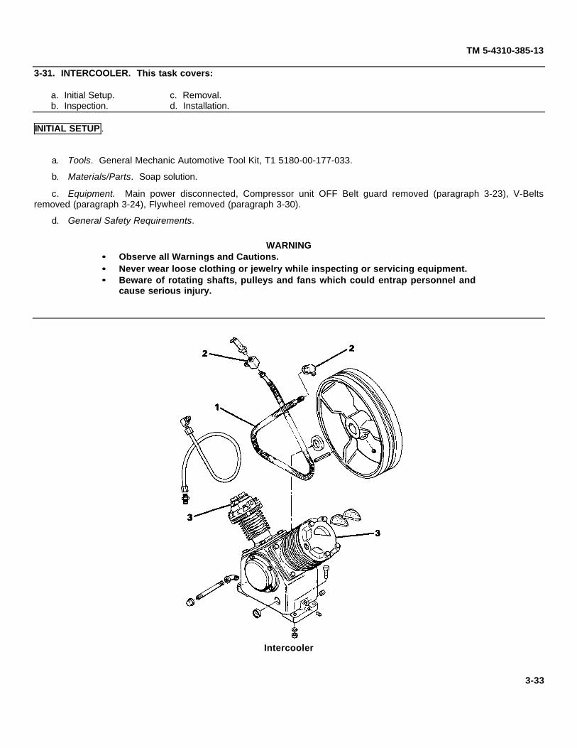
3-31. INTERCOOLER. This task covers:
a. Initial Setup. c. Removal.b. Inspection. d. Installation.
INITIAL SETUP .
a. Tools. General Mechanic Automotive Tool Kit, T1 5180-00-177-033.
b. Materials/Parts. Soap solution.
c. Equipment. Main power disconnected, Compressor unit OFF Belt guard removed (paragraph 3-23), V-Beltsremoved (paragraph 3-24), Flywheel removed (paragraph 3-30).
d. General Safety Requirements.
WARNING•• Observe all Warnings and Cautions.•• Never wear loose clothing or jewelry while inspecting or servicing equipment.•• Beware of rotating shafts, pulleys and fans which could entrap personnel and
cause serious injury.
Intercooler
3-33

TM 5-4310-385-13
INSPECTION.
WARNINGDisconnect main power and turn compressor unit off before performingmaintenance services.
a. Inspect the intercooler tubing (1) for cracks, dents, or crimping.
b. Using soap solution, inspect the intercooler fittings (2) at the cylinder heads (3) for leaks.
REMOVAL
a. Disconnect main power and turn compressor switch OFF.
b. Remove the belt guard. Refer to paragraph 3-23.
c. Remove the V-belts. Refer to paragraph 3-24.
d. Remove the flywheel. Refer to paragraph 3-30.
CAUTIONBe careful not to bend tubing when removing.
e. Remove the intercooler tubing (1) at the cylinder head fittings (2).
INSTALLATION .
a. Install the intercooler tubing (1) at the cylinder head fittings (2).
b. Install the flywheel. Refer to paragraph 3-30.
c. Install the V-belts. Refer to paragraph 3-24.
d. Install the belt guard. Refer to paragraph 3-23.
e. Connect the main power.
3-34
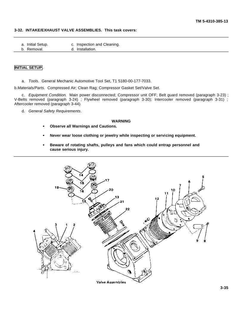
TM 5-4310-385-13
3-32. INTAKE/EXHAUST VALVE ASSEMBLIES. This task covers:
a. Initial Setup. c. Inspection and Cleaning.b. Removal. d. Installation.
INITIAL SETUP .
a. Tools. General Mechanic Automotive Tool Set, T1 5180-00-177-7033.
b.Materials/Parts. Compressed Air; Clean Rag; Compressor Gasket Set/Valve Set.
c. Equipment Condition. Main power disconnected; Compressor unit OFF; Belt guard removed (paragraph 3-23) ;V-Belts removed (paragraph 3-24) ; Flywheel removed (paragraph 3-30); Intercooler removed (paragraph 3-31) ;Aftercooler removed (paragraph 3-44).
d. General Safety Requirements.
WARNING•• Observe all Warnings and Cautions.
•• Never wear loose clothing or jewelry while inspecting or servicing equipment.
•• Beware of rotating shafts, pulleys and fans which could entrap personnel andcause serious injury.
3-35

TM 5-4310-385-13
REMOVAL
WARNINGDisconnect main power and turn compressor unit off before performingmaintenance procedures.
CAUTION
Intake valve assembly and exhaust valve assembly must not be interchanged.Identify and tag during removal.
a. Disconnect main power and turn compressor switch OFF.
b. Open drain cock and completely relieve tank pressure. Close drain cock.
c. Remove intercooler (1) at cylinder head fittings (2). Refer to paragraph 3-31.
d. Remove aftercooler (3) at cylinder head fitting (4) only. Refer to paragraph 3-44.
e. Remove capscrews (5) securing low pressure (reed valve) head (6).
f. Remove head (6).
g. Remove valve plate gasket (7) and discard.
h. Remove rolling screws (8) and reed valves (9). Identify reed valves for proper reassembly.
i. Remove valve plate (10).
j. Remove cylinder head gasket (11 ) from low pressure cylinder (12).
k. On high pressure cylinder head (13), remove valve chamber caps (14) and gaskets (15). Discard gaskets.
I. Remove valve retainers (16).
m. Remove intake valve assembly (17) and exhaust valve assembly (18).
n. Remove valve gaskets (19) and discard.
o. Remove capscrews (20) securing high pressure cylinder head (13). Remove head.
p. Remove head gasket (21) from high pressure cylinder (22) and discard.
CLEANING AND INSPECTION.
WARNINGClean with compressed air no greater than 30 psi. Protective eyewear must beworn when using compressed air.
a. Clean cylinders (12 and 22) and cylinder heads (6 and 13), especially area between cooling fins.
b. Remove old gasket material stuck to top of cylinders and bottom of heads.
c. Clean reed valves (9), valve plate (10), and valve assemblies (17 and 18) with compressed air. Wipe clean withrag.
d. Inspect reed valves (9) for flatness by placing on valve plate (10). Replace if not flat, or if it is distorted orcracked.
e. Inspect high pressure valve assemblies (17 and 18) by inserting small tool in valve holes and push parts up anddown. Movement of parts should be free. Replace valve assembly if movement is sticky. Valves are not repairable.
f. Inspect valve plate (10) for cracks or carbon pitting. Replace plate if damaged or distorted.
3-36

TM 5-4310-385-13
INSTALLATION .
CAUTIONValve gaskets should be replaced each time valves are serviced.
a. Install new gasket (21) on high pressure cylinder (22).
b. Install cylinder head (13) and capscrews (20). Tighten capscrews alternately and evenly.
c. Install intake valve assembly (17) and exhaust valve assembly (18) with new gaskets (19).
d. Screw valve retainers (16) into cylinder head.
e. Install new gaskets (15) and chamber caps (14).
f. Install new gasket (11) on low pressure cylinder (12).
g. Install valve plate (10).
h. Install reed valves (9) as identified and secure with rolling screws (8).
i. Install new valve plate gasket (7).
j. Install cylinder head (6) and secure with capscrews (5). Tighten capscrews alternately and evenly.
k. Install aftercooler (3) at high pressure head fitting (4). Refer to paragraph 3-44.
I. Install intercooler (1) at cylinder head fittings (2). Refer to paragraph 3-31.
m. Connect main power and check for proper operation upon startup. Check gaskets (7, 11,15, 19 and 21 ) andfittings (2 and 4) for leaks.
3-37

TM 5-4310-385-13
3-33. ELECTRIC MOTOR. This task covers:
a. Initial Setup. c. Short Circuit Test. e. Installation.b. Continuity Test. d. Removal.
INITIAL SETUP.
a. Tools. General Mechanic Automotive Tool Kit T1 5180-00-177-7033; Automotive Maintenance and Repair ShopEquipment, T3 4910-00-754-0654.
b. Equipment Condition. Main power disconnected; Compressor unit OFF; Belt guard removed (paragraph 3-23) ;V-Belts removed (paragraph 3-24) ; Drive pulley removed (paragraph 3-25).
c. General Safety Requirements.
WARNING•• Observe all Warnings and Cautions.•• Never wear loose clothing or jewelry while inspecting or servicing equipment.•• Beware of rotating shafts, pulleys and fans which could entrap personnel and
cause serious injury.
SET MULTIMETER TOOHMS x 1 SCALE
Continuity Test
CONTINUITY TEST.
WARNINGDisconnect main power and turn compressor unit off before performingmaintenance services.
a. Disconnect main power and turn compressor switch OFF.
b. Tag and disconnect motor leads (T1, T2, T3).
c. Set multimeter to OHMS x 1 scale.
3-38

TM 5-4310-385-13
d. Connect test leads between all pairs of motor leads:(1) T1 and T2.(2) T1 and T3.(3) T2 and T3.
e. Multimeter readings should be zero or near zero for each step. If meter reading is infinity (X), windings are open.Notify direct support.
Short Circuit Test
SHORT CIRCUIT TEST.
a. Disconnect main power and turn compressor switch OFF.
b. Tag and disconnect motor leads (T1, T2, T3).
c. Set multimeter to OHMS x 1000 scale.
d. Connect test leads between motor lead and frame:
(1) T1 and motor frame.
(2) T2 and motor frame.
(3) T3 and motor frame.
e. Multimeter readings should read infinity (X) for each step. If meter reading is zero, windings are short circuited.Notify direct support.
3-39
SET MULTIMETER TOOHMS x 1000 SCALE
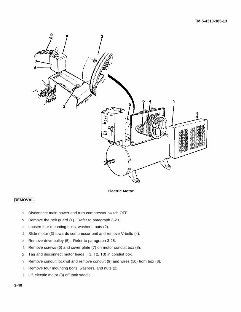
TM 5-4310-385-13
Electric Motor
REMOVAL.
a. Disconnect main power and turn compressor switch OFF.
b. Remove the belt guard (1). Refer to paragraph 3-23.
c. Loosen four mounting bolts, washers, nuts (2).
d. Slide motor (3) towards compressor unit and remove V-belts (4).
e. Remove drive pulley (5). Refer to paragraph 3-25.
f. Remove screws (6) and cover plate (7) on motor conduit box (8).
g. Tag and disconnect motor leads (T1, T2, T3) in conduit box.
h. Remove conduit locknut and remove conduit (9) and wires (10) from box (8).
i. Remove four mounting bolts, washers, and nuts (2).
j. Lift electric motor (3) off tank saddle.
3-40

TM 5-4310-385-13
INSTALLATION.
a. Position electric motor (3) on tank saddle.
b. Install, but do not tighten, mounting bolts, washers and nuts (2)
c. Route conduit (9) and wires (10) into box (8) and secure with locknut.
d. Connect motor leads (T1, T2, T3) in conduit box.
e. Install cover plate (7) and screws (6) on conduit box (8).
f. Install drive pulley and check alignment. Refer to paragraph 3-25.
g. Install V-belts and adjust belt tension. Refer to paragraph 3-24.
h. Tighten mounting hardware (2).
i. Install the belt guard. Refer to paragraph 3-23.
j. Reconnect main power.
3-41

TM 5-4310-385-13
3-34. AIR RECEIVER SYSTEM.
3-35. SAFETY VALVE. This task covers:
a. Initial Setup. c. Removal.b. Inspection. d. Installation.
INITIAL SETUP .
a. Tools. General Mechanic Automotive Tool Set, T1 5180-00-177-7033.
b. Material/Parts. Soap solution, Anti-Seize Tape.
c.Equipment Condition. As noted in procedure.
d. General Safety Requirements.
WARNING
•• Observe all Warnings and Cautions.
•• Never wear loose clothing or jewelry while inspecting or servicing equipment.
•• Beware of rotating shafts, pulleys and fans which could entrap personnel andcause serious injury.
Safety Valve
3-42
TM 5-4310-385-13
INSPECTION.
NOTE
Air tank should be under pressure to check action of safety valve.
a. Run compressor until unit kicks off (tank pressure close to 190 psi).
b. Turn compressor switch OFF.
c. Pull ring (1) on safety valve (2) and release. Air should escape when ring is pulled; valve should reseat itself andstop air release after several seconds.
d. Replace valve (2) if air continues to escape or if plunger action is sticky. Refer to next paragraph.
e. Apply soap solution to valve and check for leaks. If bubbles appear tighten valve. If leak continues, replacevalve.
REMOVAL.
WARNINGDisconnect main power and turn compressor unit off before performingmaintenance procedures.
a. Disconnect main power and turn compressor switch OFF.
WARNINGAir pressure in tank must be discharged before removal of safety valve. Removalunder pressure could cause serious injury.
b. Open drain cock (3) and completely release tank pressure. Close drain cock.
c. Unscrew safety valve (2) at hex head face at base of valve.
NOTESafety valve is not repairable. Replace if defective.
INSTALLATION.
a. Coat threads with anti-seize tape install safety valve (2) on tank and tighten. Be careful not to strip threads wheninstalling.
b. Check that drain cock (3) is closed.
c. Connect main power and turn compressor on.
d. Run compressor and check for leaks.
3-43

TM 5-4310-385-13
3-36. CHECK VALVE. This task covers:a. Initial Setup. c. Removal. e. Assembly.b. Inspection. d. Disassembly. f. Installation.
INITIAL SETUP.
a. Tool General Mechanic Automotive Tool Set, T1 5100-00-173-7033.
b. Materials/Parts, Soap solution. Replacement parts as required. Antiseize tape.
c. Equipment Condition. As noted in procedure.
d. General Safety Requirements.
WARNING
•• Observe all Warnings and Cautions.•• Never wear loose clothing or jewelry while inspecting or servicing equipment.•• Beware of rotating shafts, pulleys and fans which could entrap personnel and
cause serious injury.
Check Valve
3-44
TM 5-4310-385-13
INSPECTION.
NOTE
Air tank should be under pressure to check action of check valve.
a. Run compressor until unit kicks off (tank pressure close to 190 psi).
b. Turn compressor switch OFF.
c. Air pressure in aftercooler tubing (1) should have been released to unloader line (2) upon compressor shutdown.
CAUTIONLoosen fitting slowly. Do not remove until air has escaped.
d. Loosen aftercooler tubing fitting (3) and wait for any air release. Remove aftercooler tubing.
e. Remove unloader line (2) from check valve (4).
f. Apply soap solution to check valve (4) and check for leaks. If bubbles appear, repair or replace check valve.Refer to following paragraphs.
REMOVAL
WARNINGDisconnect main power and turn compressor unit off before performingmaintenance procedures.
a. Disconnect main power and turn compressor switch OFF.
WARNINGAir pressure in tank must be discharged before removal of check valve. Removalunder pressure could cause serious injury.
b. Open drain cock and completely release tank pressure. Close drain cock.
c. Disconnect aftercooler tubing fitting (3) from check valve (4).
d. Remove pipe.
e. Disconnect unloader line (2) from check valve (4).
f. Unscrew check valve (4) from tank.
DISASSEMBLY.
a. Remove retaining ring (5) from body (6).
b. Remove brass seat (7), spring (8), and teflon poppet (9).
c. Replace poppet (9) if worn or pitted.
3-45

TM 5-4310-385-13
ASSEMBLY.
a. Install poppet (9), spring (8), and seat (7) into body (6).
b. Install retaining ring (5).
c. Check that seat and poppet assembly move freely and seat against body dashpot.
INSTALLATION .
a. Coat threads with anti-seize tape and install check valve (4) in tank and tighten.
b. Connect unloader line (2) to check valve (4).
c. Connect aftercooler tubing fitting (3) to check valve (4).
d. Check that drain cock is closed.
e. Connect main power.
f. Run compressor and check fittings for air leaks.
3-46
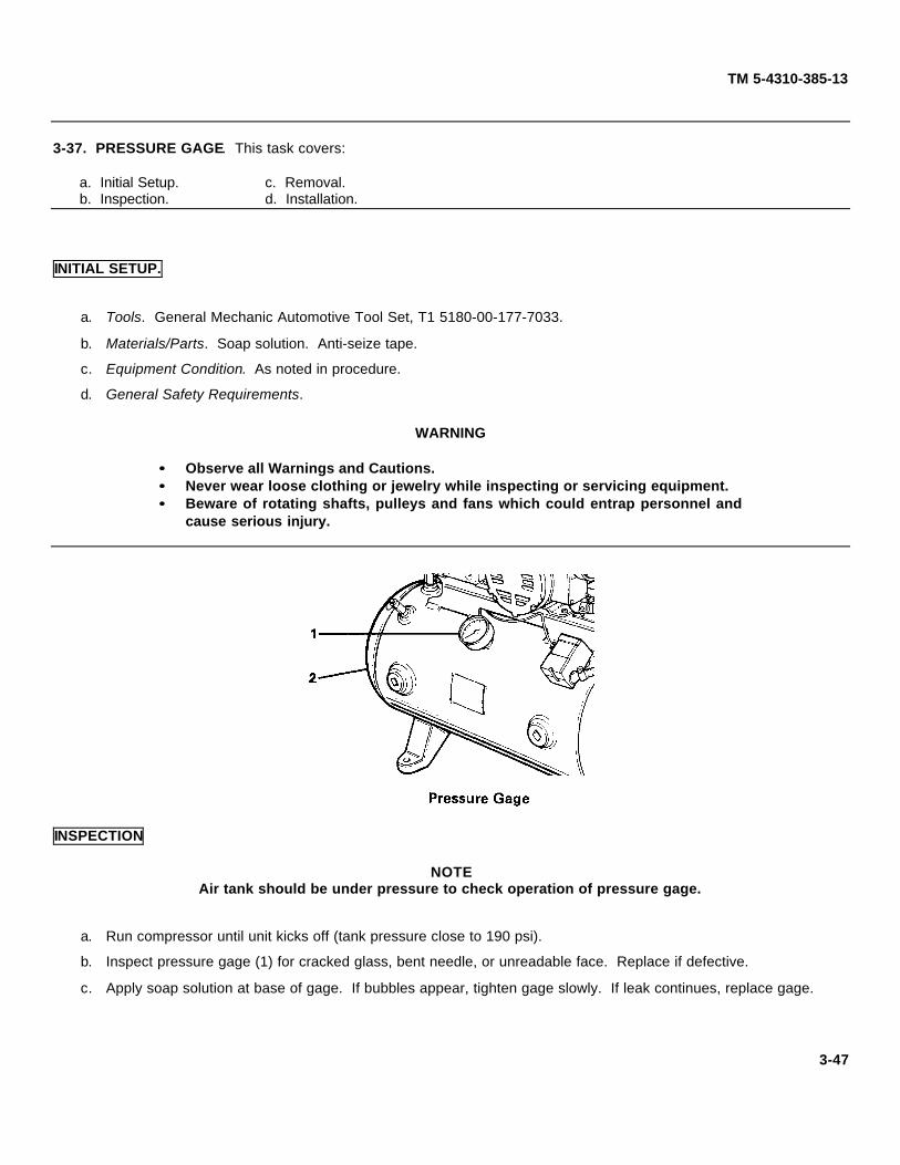
TM 5-4310-385-13
3-37. PRESSURE GAGE. This task covers:
a. Initial Setup. c. Removal.b. Inspection. d. Installation.
INITIAL SETUP.
a. Tools. General Mechanic Automotive Tool Set, T1 5180-00-177-7033.
b. Materials/Parts. Soap solution. Anti-seize tape.
c. Equipment Condition. As noted in procedure.
d. General Safety Requirements.
WARNING
•• Observe all Warnings and Cautions.•• Never wear loose clothing or jewelry while inspecting or servicing equipment.•• Beware of rotating shafts, pulleys and fans which could entrap personnel and
cause serious injury.
INSPECTION
NOTEAir tank should be under pressure to check operation of pressure gage.
a. Run compressor until unit kicks off (tank pressure close to 190 psi).
b. Inspect pressure gage (1) for cracked glass, bent needle, or unreadable face. Replace if defective.
c. Apply soap solution at base of gage. If bubbles appear, tighten gage slowly. If leak continues, replace gage.
3-47

TM 5-4310-385-13
REMOVAL.
WARNINGDisconnect main power and turn compressor unit off before performingmaintenance procedure.
a. Disconnect main power and turn compressor switch OFF.
WARNINGAir pressure in tank must be discharged before removal of pressure gage.Removal under pressure could cause serious injury.
b. Open drain cock and completely relieve tank pressure. Close drain cock.
c. Unscrew pressure gage (1) from tank.
NOTEPressure gage is not repairable. Replace if defective.
INSTALLATION.
a. Coat threads with anti-seize tape and install pressure gauge (1) on tank and tighten.
b. Check that drain cock is closed.
c. Connect main power.
d. Run compressor and check for leaks.
3-48

TM 5-4310-385-13
3-38. DRAIN COCK. This task covers:
a. Initial Setup. c. Removal.b. Inspection. d. Installation.
INITIAL SETUP.
a. Tools. General Mechanic Automotive Tool Set, T1 5180-00-173-7033.
b. Materials/Parts. Soap solution.
c. Equipment Condition. As noted in procedures.
d. General Safety Requirements.
WARNING•• Observe all Warnings and Cautions.•• Never wear loose clothing or jewelry while inspecting or servicing equipment.•• Beware of rotating shafts, pulleys and fans which could entrap personnel and
cause serious injury.
Drain Cock
3-49
TM 5-4310-385-13
INSPECTION.
NOTEAir tank should be under pressure to check drain cock for leaks.
a. Run compressor until unit kicks off (tank pressure close to 190 psi).
b. Apply soap solution to drain cock (1 ) and check for leaks. If bubbles appear, first tighten drain cock (1) and thenfitting at tank.
c. If leaks continue, replace drain cock.
d. Inspect for corrosion or damage. Replace if defective.
REMOVAL.
WARNINGDisconnect main power and turn compressor unit off before performingmaintenance procedure.
a. Disconnect main power and turn compressor switch OFF.
WARNINGAir pressure in tank must be discharged before removal of drain cock. Removalunder pressure could cause serious injury.
b. Open drain cock (1) and completely release tank pressure.
c. Unscrew drain cock (1) from tank.
NOTEDrain cock is not repairable. Replace if defective.
INSTALLATION.
a. Screw drain cock (1) securely into tank.
b. Connect main power.
c. Run compressor and check for leaks.
3-50

TM 5-4310-385-13
3-39. SHUTOFF VALVE. This task covers:
a. Initial Setup. c. Removal.b. Inspection. d. Installation.
INITIAL SETUP.
a. Tools. General Mechanic Automotive Tool Set, T1 5180-00-173-7033.
b. Material/Parts. Soap solution.
c. Equipment Condition. As noted in procedures.
d. General Safety Requirements.
WARNING•• Observe all Warnings and Cautions.•• Never wear loose clothing or jewelry while inspecting or servicing equipment.•• Beware of rotating shafts, pulleys and fans which could entrap personnel and
cause serious injury.
Shutoff Valve
3-51
TM 5-4310-385-13
INSPECTION.
NOTEAir tank should be under pressure to check shutoff valve for leaks.
a. Run compressor until unit kicks off (tank pressure close to 190 psi).
b. Apply soap solution to shutoff valve (1) and check for leaks.
c. Be sure screw (2) is tight.
d. Check lever (3) for smooth turning. Replace valve if leaks continue or lever is hard to turn.
REMOVAL
WARNINGDisconnect main power and turn compressor unit off before performingmaintenance procedures.
a. Disconnect main power and turn compressor switch OFF.
WARNINGAir pressure in tank must be discharged before removal of shutoff valve. Removalunder pressure could cause serious injury.
b. Open drain cock(7) and completely relieve tank pressure. Make sure shutoff valve (1 ) is open so pressure in airhose is also relieved. Close drain cock.
c. Unscrew air hose fitting (4) and remove hose.
d. Unscrew bushing (5) from valve (1).
e. Unscrew shutoff valve from pipe nipple (6).
INSTALLATION.
a. Install shutoff valve (1) on pipe nipple (6).
b. Install bushing (5) to valve.
c. Install air hose fitting (4).
d. Check that drain cock (7) is securely closed.
e. Connect main power.
f. Run compressor and inspect shutoff valve and fittings for leaks and proper operation.
3-52

TM 5-4310-385-13
3-40. AIR TANK. This task covers:
a. Initial Setup. b. Removal. c. Installation.
INITIAL SETUP.a. Tools. General Mechanic Automotive Tool Set, T1 5083-00-177-7033.
b. Equipment Condition. Main power disconnected; Compressor unit OFF; Air in tank discharged.
c. General Safety Requirements.
WARNING•• Observe all Warnings and Cautions.•• Never wear loose clothing or jewelry while inspecting or servicing equipment.•• Beware of rotating shafts, pulleys and fans which could entrap personnel and
cause serious injury.
REMOVAL
WARNINGDisconnect main power and turn compressor unit off before performingmaintenance procedures.
a. Disconnect main power and turn compressor switch (1) OFF.
WARNINGAir pressure in tank must be discharged before removing any tank component.Removal of any tank component under pressure could cause serious injury.
3-53

TM 5-4310-385-13
b. Open drain cock (2) and completely release tank pressure.
c. Remove belt guard (3). Refer to paragraph 3-23.
d. Remove motor starter and enclosure (4). Refer to paragraphs 3-19 and 3-20.
e. Remove electric motor (5). Refer to paragraph 3-33.
f. Remove tubing assemblies (6). Refer to paragraphs 3-31 and 3-44.
g. Remove compressor unit (7). Refer to paragraph 3-27.
h. Remove pressure switch (8). Refer to paragraph 3-21.
i. Remove safety valve (9). Refer to paragraph 3-35.
j. Remove check valve (10). Refer to paragraph 3-36.
k. Remove pressure gauge (11 ). Refer to paragraph 3-37.
I. Remove drain cock (2). Refer to paragraph 3-38.
m. Remove shutoff valve (12). Refer to paragraph 3-39.
n. Unbolt tank (13) from base.
INSTALLATION .
a. Bolt air tank (13) to base. Make sure base is on firm level ground or flooring.
b. Install shutoff valve (12). Refer to paragraph 3-39.
c. Install drain cock (2). Refer to paragraph 3-38.
d. Install pressure gage (11 ). Refer to paragraph 3-37.
e. Install check valve (10). Refer to paragraph 3-36.
f. Install safety valve (9). Refer to paragraph 3-35.
g. Install pressure switch (8). Refer to paragraph 3-21.
h. Install compressor unit (7). Refer to paragraph 3-27.
i. Install tubing assemblies (6). Refer to paragraphs 3-31 and 3-44.
j. Install electric motor (5). Refer to paragraph 3-33.
k. Adjust belt tension (paragraph 3-24) and pulley alignment (paragraph 3-25).
I. Install motor starter and enclosure (4). Refer to paragraphs 3-19 and 3-20.
m. Install belt guard (3). Refer to paragraph 3-23.
n. Close drain cock (2).
CAUTION
Before operating compressor, be sure all components and fittings are secure andtight. Also, check that wiring is correct. Check that tools and objects are clear ofunit.
o. Connect main power.
p. Turn power switch (1) on and run compressor. Inspect entire unit, check for air leaks and perform operationalcheck.
3-54
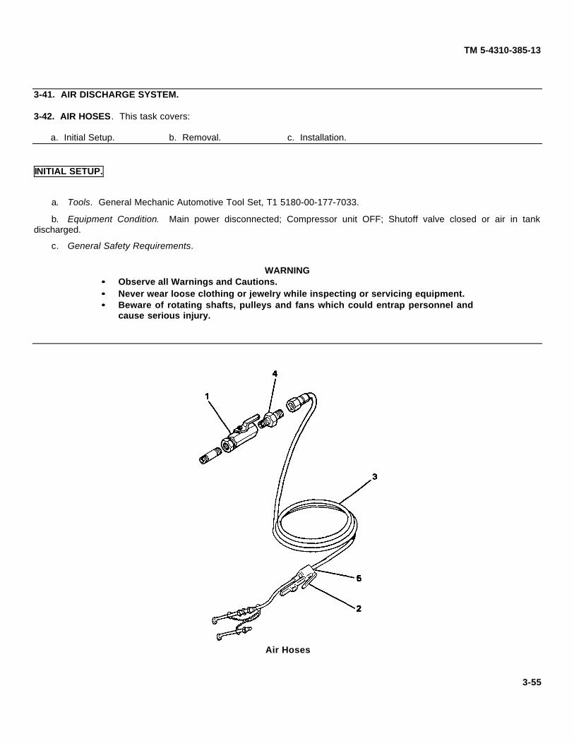
TM 5-4310-385-13
3-41. AIR DISCHARGE SYSTEM.
3-42. AIR HOSES. This task covers:
a. Initial Setup. b. Removal. c. Installation.
INITIAL SETUP.
a. Tools. General Mechanic Automotive Tool Set, T1 5180-00-177-7033.
b. Equipment Condition. Main power disconnected; Compressor unit OFF; Shutoff valve closed or air in tankdischarged.
c. General Safety Requirements.
WARNING•• Observe all Warnings and Cautions.•• Never wear loose clothing or jewelry while inspecting or servicing equipment.•• Beware of rotating shafts, pulleys and fans which could entrap personnel and
cause serious injury.
Air Hoses
3-55
TM 5-4310-385-13
REMOVAL.
a. Turn compressor switch OFF.
WARNINGShutoff valve must be closed or air in tank must be discharged before removal ofhoses. Removal under pressure could cause serious injury.
b. Turn shutoff valve (1) clockwise to close air supply.
WARNINGAir in hoses must be discharged before removing hose.
c. Depress lever (2) to discharge any air pressure in hoses (3).
d. Remove hoses at shutoff valve fitting (4) and inflator gage fittings (5).
INSTALLATION.
a. Install hoses (3) at shutoff valve fitting (4) and inflator gage fittings (5). Tighten fittings.
b. Turn shutoff valve (1) counterclockwise to open air supply.
c. Turn compressor unit ON, run compressor, and check for leaks.
3-56
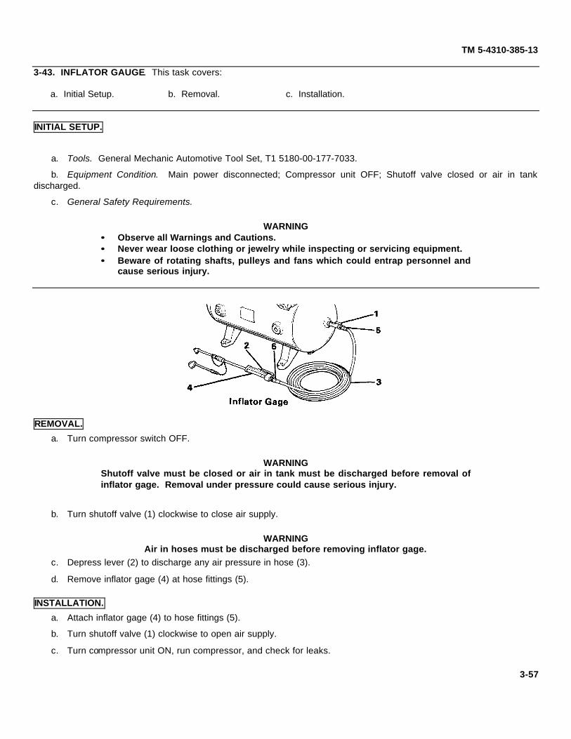
TM 5-4310-385-13
3-43. INFLATOR GAUGE. This task covers:
a. Initial Setup. b. Removal. c. Installation.
INITIAL SETUP.
a. Tools. General Mechanic Automotive Tool Set, T1 5180-00-177-7033.
b. Equipment Condition. Main power disconnected; Compressor unit OFF; Shutoff valve closed or air in tankdischarged.
c. General Safety Requirements.
WARNING•• Observe all Warnings and Cautions.•• Never wear loose clothing or jewelry while inspecting or servicing equipment.•• Beware of rotating shafts, pulleys and fans which could entrap personnel and
cause serious injury.
REMOVAL.
a. Turn compressor switch OFF.
WARNINGShutoff valve must be closed or air in tank must be discharged before removal ofinflator gage. Removal under pressure could cause serious injury.
b. Turn shutoff valve (1) clockwise to close air supply.
WARNINGAir in hoses must be discharged before removing inflator gage.
c. Depress lever (2) to discharge any air pressure in hose (3).
d. Remove inflator gage (4) at hose fittings (5).
INSTALLATION.
a. Attach inflator gage (4) to hose fittings (5).
b. Turn shutoff valve (1) clockwise to open air supply.
c. Turn compressor unit ON, run compressor, and check for leaks.
3-57
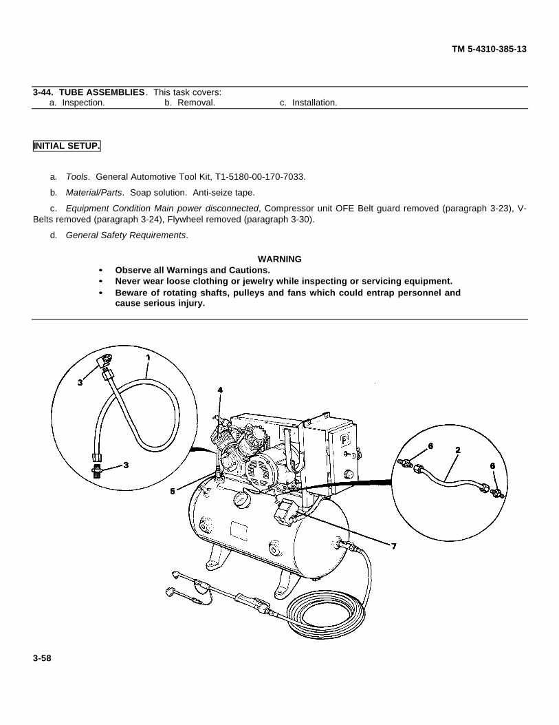
TM 5-4310-385-13
3-44. TUBE ASSEMBLIES. This task covers:a. Inspection. b. Removal. c. Installation.
INITIAL SETUP.
a. Tools. General Automotive Tool Kit, T1-5180-00-170-7033.
b. Material/Parts. Soap solution. Anti-seize tape.
c. Equipment Condition Main power disconnected, Compressor unit OFE Belt guard removed (paragraph 3-23), V-Belts removed (paragraph 3-24), Flywheel removed (paragraph 3-30).
d. General Safety Requirements.
WARNING•• Observe all Warnings and Cautions.•• Never wear loose clothing or jewelry while inspecting or servicing equipment.•• Beware of rotating shafts, pulleys and fans which could entrap personnel and
cause serious injury.
3-58
TM 5-4310-385-13
INSPECTION.
a. Inspect the after cooler tubing (1) and unloader line (2) for cracks, dents, or crimping.
b. Using soap solution, check the aftercooler fittings (3) at the cylinder head (4) and check valve (5) for leaks.
c. Using soap solution, check the unloader line fittings (6) at the check valve (5) and pressure switch (7) for leaks.
REMOVAL.
WARNINGDisconnect main power and turn compressor unit off before performingmaintenance procedures.
a. Remove the aftercooler tubing fittings (3) at the cylinder head (4) and check valve (5).
b. Remove the unloader line fittings (6) at the check valve (5) and pressure switch (7).
INSTALLATION.
WARNINGDisconnect main power and turn compressor unit off before performingmaintenance procedures.
a. Coat all threaded fittings with anti-seize tape.
b. Install the aftercooler tubing fittings (3) at the cylinder head (4) and check valve (5).
c. Install the unloader line fittings (6) at the check valve (5) and pressure switch (7).
3-59
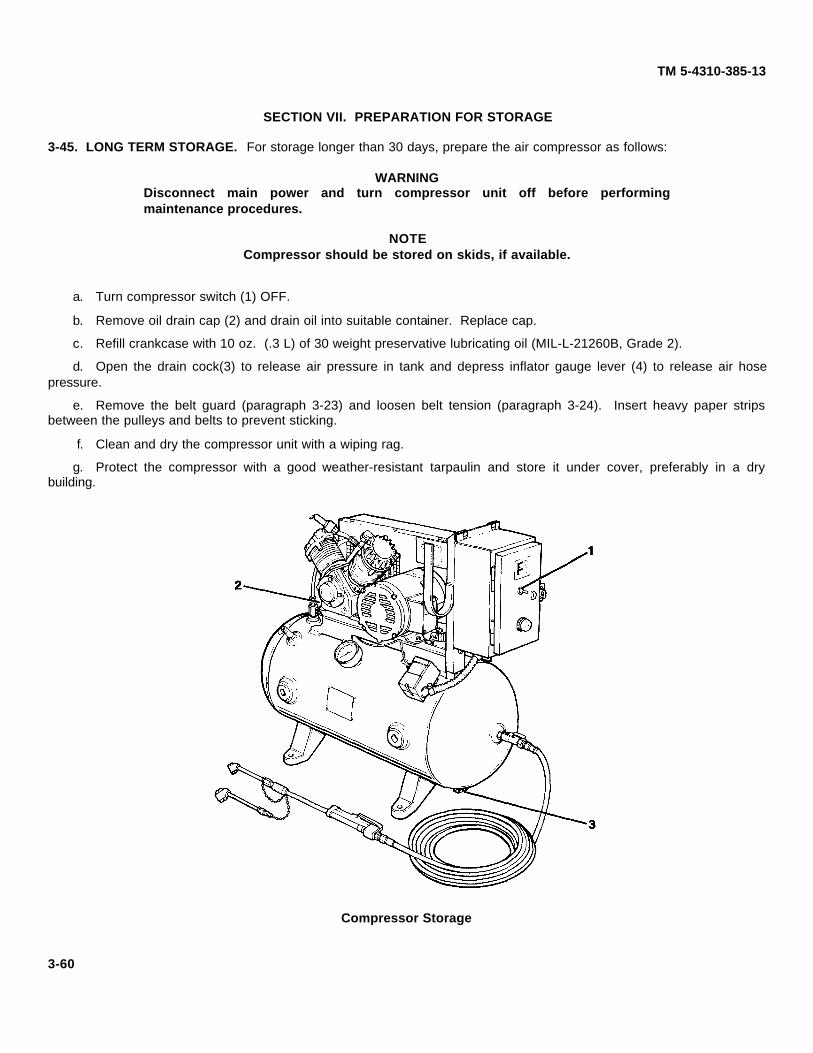
TM 5-4310-385-13
SECTION VII. PREPARATION FOR STORAGE
3-45. LONG TERM STORAGE. For storage longer than 30 days, prepare the air compressor as follows:
WARNINGDisconnect main power and turn compressor unit off before performingmaintenance procedures.
NOTECompressor should be stored on skids, if available.
a. Turn compressor switch (1) OFF.
b. Remove oil drain cap (2) and drain oil into suitable container. Replace cap.
c. Refill crankcase with 10 oz. (.3 L) of 30 weight preservative lubricating oil (MIL-L-21260B, Grade 2).
d. Open the drain cock(3) to release air pressure in tank and depress inflator gauge lever (4) to release air hosepressure.
e. Remove the belt guard (paragraph 3-23) and loosen belt tension (paragraph 3-24). Insert heavy paper stripsbetween the pulleys and belts to prevent sticking.
f. Clean and dry the compressor unit with a wiping rag.
g. Protect the compressor with a good weather-resistant tarpaulin and store it under cover, preferably in a drybuilding.
Compressor Storage
3-60

TM 5-4310-385-13CHAPTER 4. INTERMEDIATE DIRECT SUPPORT
MAINTENANCE INSTRUCTIONSSECTION I. TROUBLESHOOTING
4-1. GENERAL. This section contains troubleshooting procedures to be performed by direct support maintenance. Thisassumes that troubleshooting and maintenance procedures have already been performed at the organizational level forsimilar malfunctions. information should be reviewed in Chapter 3: Unit Maintenance Instructions; Section V.Troubleshooting; and Section VI. Organizational Maintenance Procedures.
4-2. COMPRESSOR UNIT. Direct support troubleshooting and maintenance procedures cover cylinder and crankcasecomponent replacement: cylinder block, pistons, connecting rod assemblies, crankshaft and oil seals.
4-3. ELECTRIC MOTOR. Direct support troubleshooting and maintenance procedures cover motor componentreplacement.
4-4. TROUBLESHOOTING TABLE. The following columns are used in the Troubleshooting Table.
a. Malfunctions. Malfunctions listed are the ones most likely to happen. Not all possible malfunctions can beforeseen and listed.
b. Test or inspection. Tests or inspections are listed to help you find the cause of the malfunction. The tests thatare easiest to do are listed first. The tests that are hardest to do are listed last.
c. Corrective Action. Corrective actions are listed to help eliminate the malfunction. The paragraph number of thedetailed maintenance procedure is given in parentheses.
Table 4-1. TroubleshootingMalfunction
Test or InspectionCorrective Action
COMPRESSOR1. COMPRESSOR DOES NOT PUT OUT ENOUGH AIR.
Step 1. Check for leaking gaskets between cylinder heads and cylinders, and gaskets between cylindersand crankcase.
Install new gaskets (paragraph 4-7).
Step 2. Check for worn or damaged intake or exhaust valves in low pressure cylinder.
Replace as necessary.
2. EXCESSIVE OIL CONSUMPTION.
Step 1. Check for worn or stuck piston rings, particularly oil ring.
Install new piston rings (paragraph 4-7).
Step 2. Check for leaking gasket between cylinder and crankcase, leaking gaskets betweencrankcase and crankcase cover, or leaking gasket between crankcase cover and breatherassembly cover.
Install new gaskets (paragraph 4-7).
Step 3. If oil leakage occurs between crankcase cover and breather assembly cover, check felt oil separatoron breather assembly.
Replace oil separator (paragraph 4-7).4-1
TM 5-4310-385-13
Table 4-1. Troubleshooting (Continued)
MalfunctionTest or Inspection
Corrective Action
Step 4. Check for leaking oil seal at the crankcase shaft.
Install new oil seal in crankcase (paragraph 4-7).
3. COMPRESSOR RUNS NOISY.
Step 1. Check for foreign matter, such as carbon, metal chips, etc. or damaged components in cylinderand crankcase.
Remove heads and clean cylinder; inspect crankcase (paragraph 4-7).
Step 2. Check for worn or damaged connecting rod assemblies.
Replace damaged connecting rod components (paragraph 4-8).
Step 3. Check for worn bearings.
Replace bearings as necessary (paragraph 4-9).
Step 4. Check for worn or unbalanced crankshaft.
Replace crankshaft (paragraph 4-7).
Step 5. Check for end play in crankshaft.
Remove crankcase cover gasket (shim, .005" or .010") until end play is reduced (paragraph 4-7).Removing too many gaskets may cause crankshaft to bind.
ELECTRIC MOTOR
1. MOTOR WON'T RUN.
Step 1. Test for open motor windings (paragraph 3-33).
Replace frame and stator assembly (paragraph 4-10).
Step 2. Test for shorts between windings and motor frame (paragraph 3-33).
Replace frame and stator assembly (paragraph 4-10).
2. NOISY OPERATION OF MOTOR.
Step 1. Rotate motor shaft by hand and check for rough spots or binding. If rotation is not smooth,bearings are bad.
Replace bearings (paragraph 4-10).
4-2

TM 5-4310-385-13
SECTION II. INTERMEDIATE DIRECT SUPPORT MAINTENANCE PROCEDURES
4-5. GENERAL. This section contains disassembly, assembly, inspection, and repair instructions for the compressorcomponents listed in Appendix B, Section III, Maintenance Allocation Chart. Paragraph references are listed below foreach grouping for locating repair instruction:
a. Paragraph 4-6, Compressor Assembly: Compressor Unit, Piston and Connecting Rods, Crankcase Bearings.
b. Paragraph 4-10, Electric Motor.
4-6. COMPRESSOR ASSEMBLY.
4-7. COMPRESSOR UNIT. This task covers:
a. Initial Setup. c. Inspection. e. Assembly.b. Disassembly. d. Cleaning.
INITIAL SETUP.
a. Tools. General Mechanic Automotive Tool Set, T1 5800-00-177-7033; Field Maintenance Automotive RepairShop Set, T2 4910-00-754-0705.
b. Materials/Parts. Gasket Set; Gasket Sealant; Compressed Air.
c. Equipment Condition. Compressor unit removed (paragraph 3-27) and placed on workbench; Cylinder headassemblies removed (paragraph 3-32).
d. General Safety Requirements.WARNING
•• Observe all Warnings and Cautions.
•• Never wear loose Clothing or jewelry while inspecting or servicing equipment.
•• Beware of rotating shafts, pulleys and fans which could entrap personnel andcause serious injury.
DISASSEMBLY.
WARNING
Disconnect main power and turn compressor unit off before performingmaintenance procedures.
a. Remove capscrews (1) securing cylinder (2) to crankcase (3).
CAUTION
Pistons and connecting rods may be damaged by hitting crankcase when cylinderis removed. Support pistons when removing cylinder.
b. Remove cylinder (2) by twisting slightly back and forth while pulling upward.
4-3
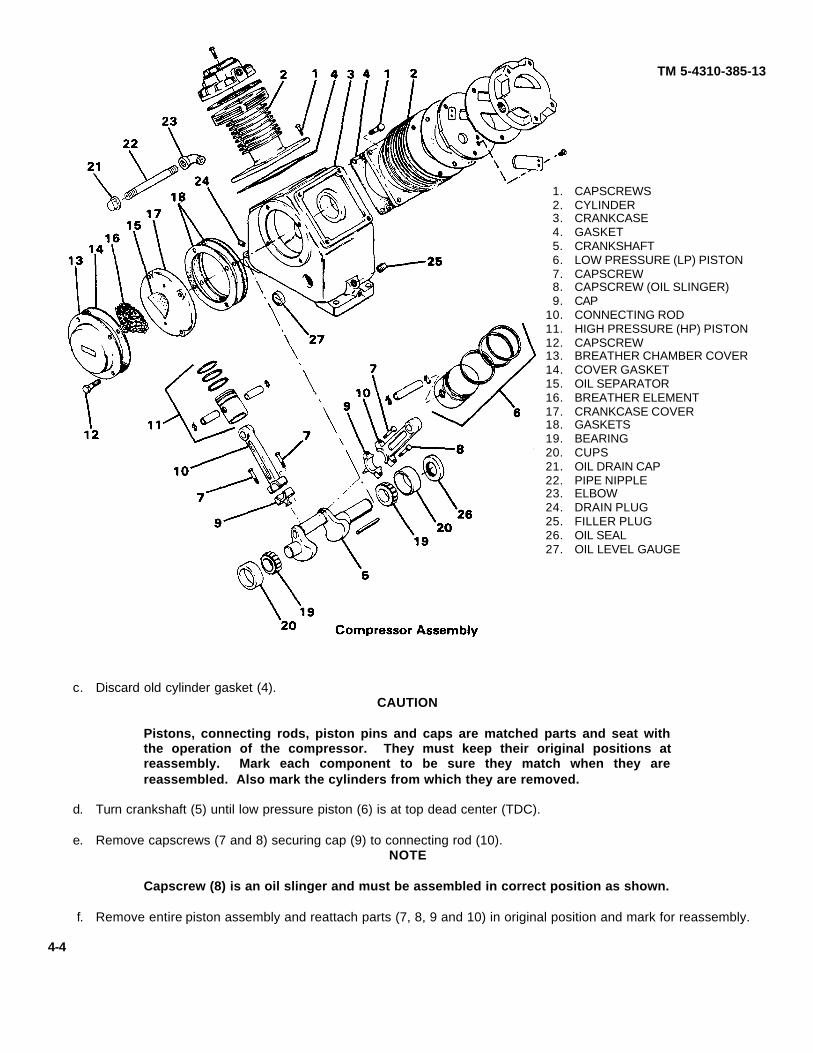
TM 5-4310-385-13
1. CAPSCREWS2. CYLINDER3. CRANKCASE4. GASKET5. CRANKSHAFT6. LOW PRESSURE (LP) PISTON7. CAPSCREW8. CAPSCREW (OIL SLINGER)9. CAP
10. CONNECTING ROD11. HIGH PRESSURE (HP) PISTON12. CAPSCREW13. BREATHER CHAMBER COVER14. COVER GASKET15. OIL SEPARATOR16. BREATHER ELEMENT17. CRANKCASE COVER18. GASKETS19. BEARING20. CUPS21. OIL DRAIN CAP22. PIPE NIPPLE23. ELBOW24. DRAIN PLUG25. FILLER PLUG26. OIL SEAL27. OIL LEVEL GAUGE
c. Discard old cylinder gasket (4).CAUTION
Pistons, connecting rods, piston pins and caps are matched parts and seat withthe operation of the compressor. They must keep their original positions atreassembly. Mark each component to be sure they match when they arereassembled. Also mark the cylinders from which they are removed.
d. Turn crankshaft (5) until low pressure piston (6) is at top dead center (TDC).
e. Remove capscrews (7 and 8) securing cap (9) to connecting rod (10).NOTE
Capscrew (8) is an oil slinger and must be assembled in correct position as shown.
f. Remove entire piston assembly and reattach parts (7, 8, 9 and 10) in original position and mark for reassembly.
4-4
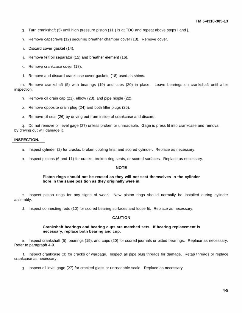
TM 5-4310-385-13
g. Turn crankshaft (5) until high pressure piston (11 ) is at TDC and repeat above steps i and j.
h. Remove capscrews (12) securing breather chamber cover (13). Remove cover.
i. Discard cover gasket (14).
j. Remove felt oil separator (15) and breather element (16).
k. Remove crankcase cover (17).
I. Remove and discard crankcase cover gaskets (18) used as shims.
m. Remove crankshaft (5) with bearings (19) and cups (20) in place. Leave bearings on crankshaft until afterinspection.
n. Remove oil drain cap (21), elbow (23), and pipe nipple (22).
o. Remove opposite drain plug (24) and both filler plugs (25).
p. Remove oil seal (26) by driving out from inside of crankcase and discard.
q. Do not remove oil level gage (27) unless broken or unreadable. Gage is press fit into crankcase and removal by driving out will damage it.
INSPECTION.
a. Inspect cylinder (2) for cracks, broken cooling fins, and scored cylinder. Replace as necessary.
b. Inspect pistons (6 and 11) for cracks, broken ring seats, or scored surfaces. Replace as necessary.
NOTE
Piston rings should not be reused as they will not seat themselves in the cylinderbore in the same position as they originally were in.
c. Inspect piston rings for any signs of wear. New piston rings should normally be installed during cylinderassembly.
d. Inspect connecting rods (10) for scored bearing surfaces and loose fit. Replace as necessary.
CAUTION
Crankshaft bearings and bearing cups are matched sets. If bearing replacement isnecessary, replace both bearing and cup.
e. Inspect crankshaft (5), bearings (19), and cups (20) for scored journals or pitted bearings. Replace as necessary.Refer to paragraph 4-9.
f. Inspect crankcase (3) for cracks or warpage. Inspect all pipe plug threads for damage. Retap threads or replacecrankcase as necessary.
g. Inspect oil level gage (27) for cracked glass or unreadable scale. Replace as necessary.
4-5

TM 5-4310-385-13
CLEANING.
WARNING
Drycleaning solvent, P-D-680 used to clean parts is potentially dangerous topersonnel and property. Avoid repeated and prolonged skin contact by wearingrubber or non-porous gloves when handling the solvent or material wet withdrycleaning solvent. Wash hands immediately after exposure with soap and waterand use a lanolin based skin cream to prevent skin drying. Do not use near openflame or excessive heat Flash point of solvent is 100°° F (38°C). Do not work withsolvent in a closed room. Be sure there is good ventilation or the solvent vaporswill build up in the air and become a poisonous mixture which can cause physicalinjury or even death.
a. Clean all parts of the compressor assembly with solvent.
WARNING
Clean with compressed air no greater than 30 psi. Protective eyewear must beworn when using compressed air.
b. Blow off parts with compressed air.
c. Dry with clean rag.
d. Replace breather element (16) and felt oil separator (15) if cleaning is not effective.
ASSEMBLY.CAUTION
Do not get sealant on bearing surfaces of oil seal.
a. Apply sealant to outside edges of oil seal (26).
b. Install oil seal (26) in crankcase by driving squarely with block of wood and hammer.
c. Install drain plug (24) and filler plugs (25).
d. Install oil drain cap (21), elbow (23) and pipe nipple (22).
NOTE
Coat all components with oil before assembly.
e. Insert flywheel portion of crankshaft through oil seal (26) and install crankshaft (5) with bearings (19) and cups(20) in crankcase.
f. Install new crankcase cover gaskets (18) used as shims (.005" and .010").
g. Position crankcase cover (17) in place and secure temporarily with capscrews (12). Check crankshaft end playand adjust as necessary be removing or adding cover gaskets (18). Crankshaft should turn freely without binding or slop(end play).
h. Remove capscrews (12) and install oil separator (15) and breather element (16).
i. Install new cover gasket (14) and breather chamber cover (13). Secure with capscrews (12).
4-6

TM 5-4310-385-13
CAUTION
Pistons, connecting rods, caps, and bushings are matched parts and seat with theoperation of the compressor. They must keep their original positions atreassembly. Mark each connecting rod and cap, piston, and bearing component tobe sure they match when they are reassembled. Also mark the cylinders fromwhich they are removed.
j. Rotate crankshaft until high pressure piston (11 ) journal is at TDC and install connecting rod (10), cap (9) andcapscrews(7 and 8). Capscrew (8) is an oil slinger and must be assembled as shown. Be sure connecting rods (10) andcap (9) mate as marked.
k. Rotate crankshaft until low pressure piston (6) journal is at TDC and repeat step i for low pressure connecting rodassembly.
NOTE
To prevent air leaking past pistons, turn rings on pistons so that ring gaps are notin line with each other.
I. Install new cylinder gasket (4).
m. Use suitable ring compressor to compress piston rings and install cylinder (2) onto crankcase.
n. Install capscrews (1) securing cylinder (2) to crankcase (3). Tighten capscrews.
o. Install cylinder head and intake/exhaust valve assemblies. Use new gaskets for reassembly. Refer toparagraph 3-32.
p. Install compressor unit on tank saddle. Refer to paragraph 3-27.
q. Fill crankcase with 10 oz. (.3 L) of OE-30 oil. Refer to paragraph 3-2 for proper viscosity.
r. Connect main power and turn compressor on.
s. Check all mating surfaces, gaskets, fittings, and mounting hardware for secure attachment.
4-7

TM 5-4310-385-13
4-8. PISTONS AND CONNECTING ROD ASSEMBLY. This task covers:
a. Initial Setup. b. Assembly. c. Disassembly.
INITIAL SETUP.
a. Tools. General Mechanic Automotive Tool Kit, T1 5180-00-177-7033; Basic Field Maintenance AutomotiveRepair Shop Set, T2 4910-00-754-0705.
b. Material/Parts. Piston Rings, Oil OE-30.
c. Equipment Condition. Compressor disassembled (paragraph 4-7).
d. General Safety Requirements.
WARNING
•• Observe all Warnings and Cautions.
•• Never wear loose clothing or jewelry while inspecting or servicing equipment.
•• Beware of rotating shafts, pulleys and fans which could entrap personnel andcause serious injury.
4-8

TM 5-4310-385-13
DISASSEMBLY.
CAUTION
Pistons, connecting rods, piston pins, and caps are matched parts and seat withthe operation of the compressor. They must keep their original positions atreassembly. Mark each component to be sure they match when they arereassembled.
a. Clamp connecting rod assembly in vise or suitable fixture. Be careful not to score pistons.
b. Remove piston rings (1) from piston (2).
c. Using suitable pliers, squeeze retaining rings (3) and remove from piston.
NOTE
To remove pin (4) on high pressure piston, loosen setscrew (8) and press outbushings (9).
d. Push out piston pins (4) and remove pistons (2) from connecting rods (5).
e. Remove capscrews (6) and rod caps (7) from connecting rod.
ASSEMBLY.
CAUTION
Pistons, connecting rods, piston pins, and caps are matched parts and seat withthe operation of the compressor. They must keep their original positions atreassembly. Mark each component to be sure they match when they arereassembled.
NOTE
Coat all parts with oil before assembly.
a. Attach capscrews (6) and rod caps (7) to connecting rods (5). Secure nuts finger-tight.
b. Clamp connecting rod (5) in vise or suitable fixture and position piston (2) on connecting rod.
c. Attach piston (2) by installing piston pins (4) through holes in pistons and connecting rods.
d. Center piston pins (4) and install retaining rings (3) in grooves on pins. Be sure retaining rings are properlyseated in grooves.
CAUTION
Piston rings must be installed correctly. The oil ring must be in the lowest groove.
e. Install piston rings (1) on pistons.
4-9
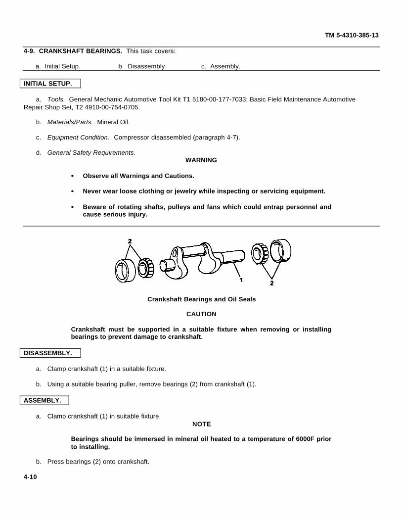
TM 5-4310-385-13
4-9. CRANKSHAFT BEARINGS. This task covers:
a. Initial Setup. b. Disassembly. c. Assembly.
INITIAL SETUP.
a. Tools. General Mechanic Automotive Tool Kit T1 5180-00-177-7033; Basic Field Maintenance Automotive Repair Shop Set, T2 4910-00-754-0705.
b. Materials/Parts. Mineral Oil.
c. Equipment Condition. Compressor disassembled (paragraph 4-7).
d. General Safety Requirements.WARNING
•• Observe all Warnings and Cautions.
•• Never wear loose clothing or jewelry while inspecting or servicing equipment.
•• Beware of rotating shafts, pulleys and fans which could entrap personnel andcause serious injury.
Crankshaft Bearings and Oil Seals
CAUTION
Crankshaft must be supported in a suitable fixture when removing or installingbearings to prevent damage to crankshaft.
DISASSEMBLY.
a. Clamp crankshaft (1) in a suitable fixture.
b. Using a suitable bearing puller, remove bearings (2) from crankshaft (1).
ASSEMBLY.
a. Clamp crankshaft (1) in suitable fixture.NOTE
Bearings should be immersed in mineral oil heated to a temperature of 6000F priorto installing.
b. Press bearings (2) onto crankshaft.
4-10
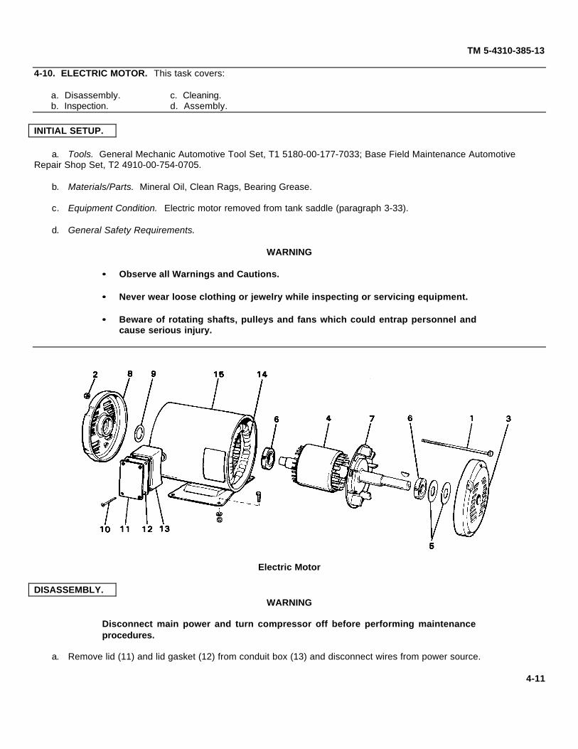
TM 5-4310-385-13
4-10. ELECTRIC MOTOR. This task covers:
a. Disassembly. c. Cleaning.b. Inspection. d. Assembly.
INITIAL SETUP.
a. Tools. General Mechanic Automotive Tool Set, T1 5180-00-177-7033; Base Field Maintenance Automotive Repair Shop Set, T2 4910-00-754-0705.
b. Materials/Parts. Mineral Oil, Clean Rags, Bearing Grease.
c. Equipment Condition. Electric motor removed from tank saddle (paragraph 3-33).
d. General Safety Requirements.
WARNING
•• Observe all Warnings and Cautions.
•• Never wear loose clothing or jewelry while inspecting or servicing equipment.
•• Beware of rotating shafts, pulleys and fans which could entrap personnel andcause serious injury.
Electric Motor
DISASSEMBLY.WARNING
Disconnect main power and turn compressor off before performing maintenanceprocedures.
a. Remove lid (11) and lid gasket (12) from conduit box (13) and disconnect wires from power source.
4-11

TM 5-4310-385-13
b. Remove electric motor from air tank base. Refer to paragraph 3-33.
NOTE
Before beginning disassembly, slowly rotate motor shaft by hand to check outbearings. If you notice any rough spots or binding, bearings are bad and must bereplaced. Bearings are sealed and cannot be visually inspected.
c.Remove four thru bolts (1) and nuts (2).
d. Mark endplates (3, 8) and remove front endplate (3).
e. Remove rotor assembly (4).
f. Remove bearing guards (5), if present. (Guards are used as shims for adjusting shaft end play.)
g. Using a suitable bearing puller, remove bearings (6) if any binding or rough spots were noticed prior todisassembly.
h. Remove cooling fan (7).
i. Remove rear endplate (8).
j. Remove thrust washer (9).
k. Remove screws (10) from conduit box lid (11).
INSPECTION.
a. Inspect leads and windings (14) of stator assembly (15) for evidence of cracked or burned insulation. Replace if leads or windings are damaged.
b. Inspect rotor and shaft assembly (4) for loose or damaged fan. If damaged, replace motor.
c. Remove any small nicks on keyway with file.
d. Inspect bearings (6) for wear or loose roller cone. Replace as necessary.
e. Inspect endplates (3 and 8) for cracks or plugged vent slots.
f. Inspect bearing guards (5) and thrust washer (9) for cracks or bends. Replace as necessary.
CLEANING.WARNING
Clean motor components with compressed air no greater than 30 psi. Eyeprotective wear must be worn when cleaning with compressed air or scrapingpaint.
a. Remove any loose paint from frame.
b. Blow off stator and rotor assemblies (4 and 1 5) with compressed air. Wipe rotor assembly (4) with clean rag.
c. Wipe off bearings (6) with clean rag if grease is dry or dirty. Apply a coat of new bearing grease.
d. Clean endplate (3 and 8) vent slots with compressed air and wipe off with clean rag.
4-12

TM 5-4310-385-13
ASSEMBLY.
a. Install conduit box lid gasket (12), and lid (11 ) and secure with screws (10).
b. Install thrust washer (9) in rear endplate (8).
c. Install rear endplate (8).
NOTE
Bearings should be immersed in mineral oil heated to a temperature of 6000Fahrenheit prior to installing.
d. Press bearings (6) onto rotor assembly (4).
e. Install rotor assembly (4).
f. Install bearing guards (5) into front endplate (3) if any were removed.
g. Install front endplate (3).
h.Install thru bolts (1) and nuts (2). Tighten nuts.
i. Install electric motor onto tank frame. Refer to paragraph 3-33.
4-13 (4-14/Blank)

TM 5-4310-385-13
APPENDIX A. REFERENCES
A-1. SCOPE. This appendix lists all forms, field manuals, and technical manuals referenced in this manual.
A-2. FORMS.
Equipment Inspection and Maintenance Work Sheet ................................................................................ DA Form 2404Quality Deficiency Report .................................................................................................................................. SF 368Recommended Changes to DA Publications ......................................................................................... DA Form 2028-2
A-3. TECHNICAL MANUALS.
Unit and Intermediate Direct Support Maintenance Repair Parts and Special Tools List,Compressor Unit, Reciprocating Air, Electric Motor Driven, Model 20-918 .......................................... TM 5-4310-385-23PThe Army Maintenance Management System (TAMMS) .......................................................................DA PAM 738-750Hand Portable Fire Extinguishers Approved for Army Users ................................................................TB 5-4200-200-10Administrative Storage of Equipment ..........................................................................................................TM 740-90-1Procedures for Destruction of Equipment to Prevent Enemy Use ...............................................................TM 750-244-3
A-4. MISCELLANEOUS PUBLICATIONS.
Fuels, Lubricants, Oils and Waxes .................................................................................................................. C91001L
A-1 (A-2/Blank)

TM 5-4310-385-13APPENDIX B. MAINTENANCE ALLOCATION CHART
SECTION I. INTRODUCTIONB-1. GENERAL.
a. This section provides a general explanation of all maintenance and repair functions authorized at variousmaintenance categories.
b. The Maintenance Allocation Chart (MAC) in Section II designates overall authority and responsibility for theperformance of maintenance functions on the identified end item or component. The application of the maintenancefunctions to the end item or component will be consistent with the capacities and capabilities of the designatedmaintenance categories.
c. Section III lists the tools and test equipment (both special tools and common tool sets) required for eachmaintenance function as referenced from Section II.
d. Section IV contains supplemental instructions and explanatory notes for a particular maintenance function.
B-2. MAINTENANCE FUNCTIONS. Maintenance functions will be limited to and defined as follows:
a. Inspect. To determine the serviceability of an item by comparing its physical, mechanical, and/or electricalcharacteristics with established standards through examination (e.g., by sight, sound, or feel).
b. Test. To verify serviceability by measuring the mechanical, pneumatic, hydraulic, or electrical characteristics ofan item and comparing those characteristics with prescribed standards.
c. Service. Operations required periodically to keep an item in proper operating condition, i.e., to clean (includesdecontaminate, when required), to preserve, to drain, to paint, or to replenish fuel, lubricants, chemical fluids, or gases.
d. Adjust. To maintain or regulate, within prescribed limits, by bringing into proper or exact position, or by setting theoperating characteristics to specified parameters.
e. Align. To adjust specified variable elements of an item to bring about optimum or desired performance.
f. Calibrate. To determine and cause corrections to be made or to be adjusted on instruments or test, measuring,and diagnostic equipment’s used in precision measurement. Consists of comparisons of two instruments, one of which isa certified standard of known accuracy, to detect and adjust any discrepancy in the accuracy of the instrument beingcompared.
g. Remove/install. To remove and install the same item when required to perform service or other maintenancefunctions. Install may be the act of emplacing, seating, or fixing into position a spare, repair part, or module (componentor assembly) in a manner to allow the proper functioning of an equipment or system.
h. Replace. To remove an unserviceable item and install a serviceable counterpart in its place.
i. Repair. The application of maintenance services (inspect, test, service, adjust, align, calibrate or replace) or othermaintenance actions (welding, grinding, riveting, straightening, facing, remachining or resurfacing) to restore serviceability to an item by correcting specific damage, fault, malfunction, or failure in a part, subassembly, module (componentor assembly), end item, or system.
j. Overhaul. That maintenance effort (service/action) prescribed to restore an item to a completelyserviceable/operational condition as required by maintenance standards in appropriate technical publications (i.e.,DMWR). Overhaul is normally the highest degree of maintenance performed by the Army. Overhaul does not normallyreturn an item to like new conditions.
k. Rebuild. Consists of those services/actions necessary for the restoration of unserviceable equipment to a likenew condition in accordance with original manufacturing standards. Rebuild is the highest degree of materialmaintenance applied to Army equipment. The rebuild operation includes the act of returning to zero those agemeasurements (hours/miles, etc.) considered in classifying Army equipment/components.
B-1

TM 5-4310-385-13B-3. EXPLANATION OF COLUMNS IN THE MAC, SECTION II.
a. Column 1, Group Number. Column 1 lists functional group code numbers, the purpose of which is to identifymaintenance significant components, assemblies, subassemblies, and modules with the next higher assembly.
b. Column 2 Component/Assembly. Column 2 contains the names of components, assemblies, subassemblies, andmodules for which maintenance is authorized.
c. Column 3 Maintenance Function. Column 3 lists the functions to be performed on the item listed in Column 2.(For detailed explanation of these functions, see paragraph B-2.)
d. Column 4 Maintenance Category. Column 4 specifies, by the listing of a work time figure in the appropriatesubcolumn(s), the category of maintenance authorized to perform the function listed in Column 3. This figure representsthe active time required to perform that maintenance function at the indicated category of maintenance. If the number ofcomplexity of the tasks within the listed maintenance function vary at different maintenance categories, appropriate worktime figures will be shown for each category. The work time figure represents the average time required to restore anitem (assembly. subassembly, component module, end item, or system) to a serviceable condition under typical fieldoperating conditions. This time includes preparation time (including any necessary disassembly/assembly time),troubleshooting/fault location time, and quality assurance/quality control time in addition to the time required to performthe specific tasks identified for the maintenance functions authorized in the maintenance allocation chart. The symboldesignations for the various maintenance categories are as follows:
C .............................................................................................................................................. Operator or Crew (UnitO ............................................................................................................................. Organizational Maintenance (Unit)F ..................................................................................................................Direct Support Maintenance (Intermediate)H ...............................................................................................................General Support Maintenance (Intermediate)D ...................................................................................................................................................Depot Maintenance
e. Column 5, Tools and Equipment. Column 5 specifies, by code, those common tool sets (not individual tools) andspecial tools, TMDE, and support equipment required to perform the designated function.
f. Column 6 Remarks. This column contains remarks or added information pertaining to maintenance functions.
B-4. EXPLANATION OF COLUMNS in TOOL AND TEST EQUIPMENT REQUIREMENTS, SECTION III.
a. Column 1, Reference Code. The tool and test equipment reference code correlates with a code used in the MAC,Section II, Column 5.
b. Column 2 Maintenance Category. The lowest category of maintenance authorized to use the tool or testequipment.
c. Column 3, Nomenclature. Name or identification of the tool or test equipment.
d. Column 4, National Stock Number. The National stock number of the tool or test equipment.
e. Column 5, Tool Number. The manufacturer's part number, if available.
B-5. EXPLANATION OF COLUMNS in REMARKS, SECTION IV.
a. Column 1, Reference Code. The code recorded in column 6 of the MAC (Section II), as applicable.
b. Column 2 Remarks. This column lists information pertinent to the maintenance function being performed asindicated in the MAC (Section II).
B-2

(1)
GroupNumber
(2)
Component/Assembly
(3)
MaintenanceFunction
(4)
Maintenance Level
(5)
Tools andEquipment
(6)
RemarksUnit Intermediate Depot
C O F H D
TM 5-4310-385-13SECTION II. MAINTENANCE ALLOCATION CHART
01 MOTOR CONTROLS
Starter, Electric Motor, Inspect 0.1Enclosure and Wiring Replace 0.7 T1
Repair 1.0 T1 A
Pressure Switch Inspect 0.1Adjust 0.2 T1Replace 0.5 T1
02 COMPRESSOR DRIVE
Guard Assembly, Inspect 0.1Belt Replace 1.0 T1
Repair 0.5 T1 B
Belts, V. Matched Set Inspect 0.1Replace 0.3 T1Adjust 0.2 T1
Pulley, Drive Inspect 0.1Replace 0.5 T1, T3Align 0.2 T1,
03 COMPRESSOR Inspect 0.2 T1UNIT Service 0.2 T1
Replace 2.0 T1Repair 2.0 T1, T2 A
Safety Interstage Inspect 0.1Valve Replace 0.2 T1
Oil Filler, Drain Inspect 0.1and Plugs Replace 0.2 T1
Flywheel Inspect 0.2 T1Replace 0.8 T1, T3
Intercooler Assembly Inspect 0.2 T1Replace 0.5 T1
Intake/Exhaust Inspect 0.2 T1Valve Assemblies Replace 1.0 T1
Cylinder Block and Inspect 0.3 T1, T2Pistons, Connecting Replace 0.5 T1, T2Rods Repair 2.0 T1, T2 A
Crankshaft and Inspect 0.4 T1, T2Bearings Replace 1.0 T1, T2
Repair 2.0 T1, T2 A
B-3
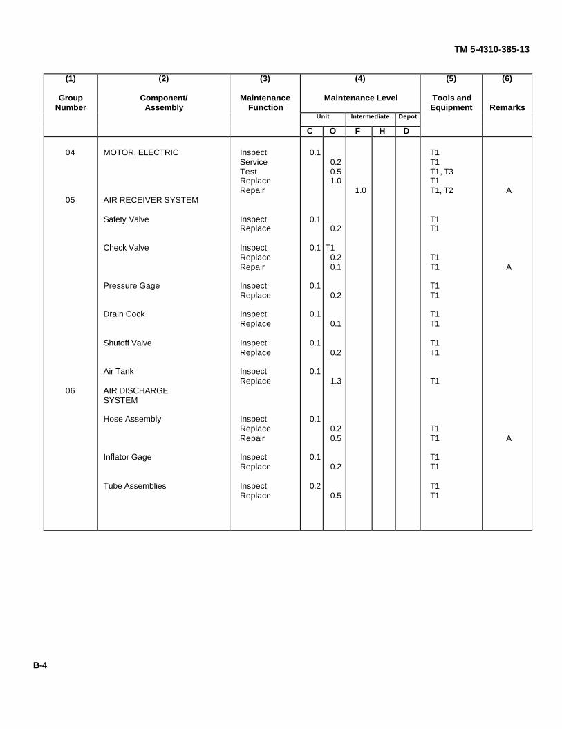
(1)
GroupNumber
(2)
Component/Assembly
(3)
MaintenanceFunction
(4)
Maintenance Level
(5)
Tools andEquipment
(6)
RemarksUnit Intermediate Depot
C O F H D
TM 5-4310-385-13
04 MOTOR, ELECTRIC Inspect 0.1 T1Service 0.2 T1Test 0.5 T1, T3Replace 1.0 T1Repair 1.0 T1, T2 A
05 AIR RECEIVER SYSTEM
Safety Valve Inspect 0.1 T1Replace 0.2 T1
Check Valve Inspect 0.1 T1Replace 0.2 T1Repair 0.1 T1 A
Pressure Gage Inspect 0.1 T1Replace 0.2 T1
Drain Cock Inspect 0.1 T1Replace 0.1 T1
Shutoff Valve Inspect 0.1 T1Replace 0.2 T1
Air Tank Inspect 0.1Replace 1.3 T1
06 AIR DISCHARGESYSTEM
Hose Assembly Inspect 0.1Replace 0.2 T1Repair 0.5 T1 A
Inflator Gage Inspect 0.1 T1Replace 0.2 T1
Tube Assemblies Inspect 0.2 T1Replace 0.5 T1
B-4

TM 5-4310-385-13
SECTION III. TOOL AND TEST EQUIPMENT REQUIREMENTS
(1) (2) (3) (4) (5)Reference Maintenance National/NATO Tool
Code Level Nomenclature Stock Number NumberT1 C, O, F, H Tool Kit, General Mechanic, Automotive 5180-00-177-7033
T2 F Shop Set, Automotive Repair, Field 4910-00-754-0705Maintenance, Basic
T3 O Shop Equipment Automotive Maintenance 4910-00-754-0654and Repair: Organization, Common No. 1
SECTION IV. REMARKS
A - Repair by replacing components.
B - Repair by welding and/or hammering out dents as needed.
B-5 (B-6/Blank)

TM 5-4310-385-13
APPENDIX C. COMPONENTS OF END ITEM AND BASIC ISSUE ITEMS
SECTION I. INTRODUCTION
C-1. SCOPE. This appendix lists Components of and Basic Issue Items (B11) for the Air Compressor to help youinventory items required for safe and efficient operation.
C-2. GENERAL. The components of end item list are divided into the following sections:
a. Section II. Components of the End Item. These items, when assembled, comprise the Air Compressor and mustaccompany it whenever it is transferred or turned in. These illustrations will help you identify these items.
b. Section III. Basic Issue Items. These are minimum essential items required to place the Air Compressor inoperation, to operate it and to perform emergency repairs. Although shipped separately packed, they must accompanythe Air Compressor during operation and whenever it is transferred between accountable officers. The illustrations willassist you with hard-to-identify items. This manual is your authority to requisition replacement B11 based on Table(s) ofOrganization and Equipment (TOE) /Modification Table of Organization and Equipment (MTOE) authorization of the enditem.
C-3. EXPLANATION OF COLUMNS.
a. Illustration. This column is divided as follows:
(1) Figure Number. Indicates the figure number of the illustration on which the item is shown (if applicable).
(2) Item Number. The number used to identify item called out in the illustration.
b. National Stock Number (NSN). Indicates the national stock number assigned to the end item which will be usedfor requisitioning.
c. Part Number (P/N). Indicates the primary number used by the manufacturer which controls the design andcharacteristics of the item by means of its engineering drawings, specifications, standards and inspection requirements toidentify an item or range of items.
d. Description. Indicates the federal hem name and, if required, a minimum description to identify the item.
e. Location. The physical location of each item listed is given in this column. The lists are designed to inventory allitems in one area of the major item before moving on to an adjacent area.
f. Usable on Code. "Usable On" codes are included to help you identify which component items are used on thedifferent models. Identification of the codes used in this list are:
CODE USED ON
g. Quantity Required (Qty. Reqd). This column lists the quantity of each item required for a complete major item.
h. Quantity. This column is left blank for use during inventory. Under the received column, list the quantity youactually receive on your major item. The date columns are for use when you inventory the major item at a later date, suchas for shipment to another site.
C-1

TM 5-4310-385-13
SECTION II. COMPONENTS OF END ITEM
(1) (2) (3) (4) (5) (6) (7) (8)Illustration Quantity
National Part No. UsableItem Stock & On QtyNo. No. FSCM Description Location Code Reqd Rcvd Date Date Date
1 4720-00- 86-751 Hose Assembly, Air Air Tank 1874-3179 (04718)
2 4910-00- 61J2-1506 Inflator Gage Air Hose 1204-2644 (94894) Assembly
SECTION III. BASIC ISSUE ITEMS
(1) (2) (3) (4) (5) (6) (7) (8)Illustration Quantity
National Part No. UsableItem Stock & On QtyNo. No. FSCM Description Location Code Reqd Rcvd Date Date Date
TM 5-4310-385-13 1
Operator's, Unit andIntermediate DirectSupport Mainten-ance Manual forCompressor, Recip-rocating, Air; ElectricMotor Driven, 5 cfm,175 psi
C-2

TM 5-4310-385-13
APPENDIX D. ADDITIONAL AUTHORIZATION LIST
SECTION I. INTRODUCTION
D-1. SCOPE. This appendix lists additional items authorized for the support of the Air Compressor.
D-2. GENERAL. This list identifies items that do not have to accompany the Air Compressor and that do not have to beturned in with it. These items are authorized to you by CTA, MTOE, TDA or JTA.
D-3. EXPLANATION OF LISTING. Not applicable.
SECTION II. ADDITIONAL AUTHORIZATION LIST
(1) (2) (3) (4)National Part Number Usable
Stock & On Qty.Number FSCM Description Code U/M Auth
4210-00-555-8837 Fire Extinguisher EA 1
D-1 (D-2/Blank)

TM 5-4310-385-13APPENDIX E. EXPENDABLE/DURABLE SUPPLIES AND MATERIALS LIST
SECTION I. INTRODUCTION
E-1. SCOPE. This appendix lists expendable/durable supplies and materials needed to operate and maintain the AirCompressor Unit.
This listing is for informational purposes only and is not authority to requisition the listed items. These items areauthorized to you by CTA 50-970, Expendable/Durable Items. (Except Medical, Class V, Repair Parts, and HeraldicItems), or CTA 8-100, Army Medical Department Expendable/Durable Items.
E-2. EXPLANATION OF COLUMNS.
a. Column 1 Item Number. This number is assigned to the entry in the listing.
b. Column 2 Level. This column identifies the lowest level of maintenance that requires the listed item.
C .......................................................................................................................................................... Operator/CrewO ...................................................................................................................................... Organizational MaintenanceF ........................................................................................................................................Direct Support MaintenanceH .................................................................................................................................... General Support Maintenance
c. Column 3- National Stock Number. This is the National stock number assigned to the item; use to request orrequisition the item.
d. Column 4 - Description. Indicates the Federal Hem name and, if required, a description to identify the item. Thelast line for each item indicates the part number followed by the Federal Supply Code for Manufacturer (FSCM) inparentheses, if applicable.
e. Column 5 - Unit of Measure (U/M). Indicates the measure used in performing the actual maintenance function.This measure is expressed by a two-character alphabetical abbreviation (e.g., ea, in., pr). If the unit of measure differsfrom the unit of issue, requisition the lowest unit of issue that will satisfy your requirements.
Expendable Supplies and Materials List
(1) (2) (3) (4) (5)National
Item StockNumber Level Number Description U/M
1 C, O, F 6850-00-274-5421 Dry Cleaning Solvent, P-D-680 gal.
2 C 7920-00-205-1711 Rag, Wiping lb.
3 C, O, F 9150-00-190-0904 GAA Grease, Auto/Artillery MIL-G-10924 (81349) lb.
4 C, O, F 9150-00-181-9858 Lubricating Oil, Engine OE 30 MIL-L-2104 (81349) gal.
5 C, O, F Mineral Oil gal.
6 C, O, F 8415-00-753-6553 Gloves, Toxicological Agents Protective pair
7 C, O, F 7930-00-068-1669 Soap, Mild gal.
8 O, F 8020-00-263-3873 Brush, Medium, Oval ea.
9 O, F 8030-01-044-5034 Compound, Anti-Seize lb.
10 O, F 8030-00-889-3534 Tape, Anti-Seize ea.E-1 (E-2/Blank)

TM 5-4310-385-13
INDEX
ParagraphNumber
AAdjustments
Pressure Switch .............................................................................................................................................. 3-21Adjustments, V-Belts........................................................................................................................................ 3-24
Aftercooler (Tubing Assembly) ............................................................................................................................... 3-44Air Hose................................................................................................................................................................ 3-42Air Filter .............................................................................................................................................Table 2-1, Item 2Air Tank ................................................................................................................................................................ 3-40Alignment, Drive Pulley .......................................................................................................................................... 3-25
BBearings, Electric Motor ......................................................................................................................................... 4-10Belt Guard............................................................................................................................................................. 3-23Belts, V................................................................................................................................................................. 3-24
CCheck Valve .......................................................................................................................................................... 3-36Compressor Assembly
Replace........................................................................................................................................................... 3-27Repair . ............................................................................................................................................................. 4-7
Controls, Operator's ................................................................................................................................................. 2-1Crankshaft Bearings ................................................................................................................................................ 4-9Crankshaft .............................................................................................................................................................. 4-7
DData Plate, Location............................................................................................................................................... 1-11Draincock.............................................................................................................................................................. 3-38Drive Pulley .......................................................................................................................................................... 3-25
EElectric Motor
Repair ............................................................................................................................................................. 4-10Replace........................................................................................................................................................... 3-33Test ............................................................................................................................................................... 3-33
Enclosure, Motor Starter ........................................................................................................................................ 3-19Exhaust Valves ...................................................................................................................................................... 3-32Equipment Data..................................................................................................................................................... 1-10
FFilter, Air .............................................................................................................................................Table 2-1, Item 2Flywheel ............................................................................................................................................................... 3-30
I-1

TM 5-4310-385-13
INDEX (Continued)Paragraph
Number
GGage, Inflator......................................................................................................................................................... 3-43Gage, Pressure...................................................................................................................................................... 3-37Guard, Belt............................................................................................................................................................ 3-23
HHoses, Air ............................................................................................................................................................. 3-42
IInflator Gage.......................................................................................................................................................... 3-43Intake Valves ........................................................................................................................................................ 3-32Intercooler ............................................................................................................................................................. 3-31Interstage Valve, Safety ......................................................................................................................................... 3-28
J
K
LLubrication
Compressor....................................................................................................................................................... 3-2Electric Motor .................................................................................................................................................... 3-3
MMaintenance Allocation Chart (MAC).........................................................................................................................B-1Maintenance, Forms and Records ............................................................................................................................ 1-3Motor, Electric
Repair ............................................................................................................................................................. 4-10Replace........................................................................................................................................................... 3-33Test ................................................................................................................................................................ 3-33
Motor, Starter ........................................................................................................................................................ 3-20Motor, Starter Enclosure......................................................................................................................................... 3-19
N
OOil Change ............................................................................................................................................................. 3-2Oil Seal ................................................................................................................................................................... 4-7Operation
Principles of..................................................................................................................................................... 1-13Sandy and Dusty Conditions............................................................................................................................. 2-10Extreme Heat .................................................................................................................................................. 2-11Compressor....................................................................................................................................................... 2-8
Operator's Controls and Indicators ........................................................................................................................... 2-1
I-2

TM 5-4310-385-13
INDEX (Continued)Paragraph
Number
PPistons, Connecting Rods ....................................................................................................................................... 4-8Preparation for Use................................................................................................................................................ 3-45Preparation for Storage ......................................................................................................................................... 3-45Pressure Gage ..................................................................................................................................................... 3-37Pressure Switch..................................................................................................................................................... 3-21
Q
R
SSafety Interstage Valve ......................................................................................................................................... 3-28Safety Valve, Tank ................................................................................................................................................ 3-35Seal, Oil ................................................................................................................................................................. 4-7Shutoff Valve ........................................................................................................................................................ 3-39Safety Warnings ......................................................................................................................................................... i
TTank, Air ............................................................................................................................................................... 3-40
UUnloader Line (Tubing Assembly) .......................................................................................................................... 3-44
VValve, Check ......................................................................................................................................................... 3-36Valve, Interstage Safety ........................................................................................................................................ 3-28Valve, Safety, Tank ................................................................................................................................................ 3-35Valve, Shutoff........................................................................................................................................................ 3-39Valves, Intake and Exhaust .................................................................................................................................... 3-32V-Belts ................................................................................................................................................................. 3-24
WWarning Decal, Location ........................................................................................................................................ 1-12Warranty ................................................................................................................................................................ 1-5
XYZ
I-3 (I-4/Blank)
TM 5-4310-385-13
By Order of the Secretary of the Army:CARL E. VUONO
General, United States ArmyChief of Staff
Official:
R. L. DILWORTHBrigadier General, United States Army
The Adjutant General
DISTRIBUTION:To be distributed in accordance with DA Form 12-25A, Operator, Unit and Intermediate Direct Support Maintenance
requirements for Compressor, Reciprocating, Air, Electric, 5 CFM, 175 PSI (20-904, 20-911).
¶U.S. GOVERNMENT PRINTING OFFICE: 1987-554-120/60024

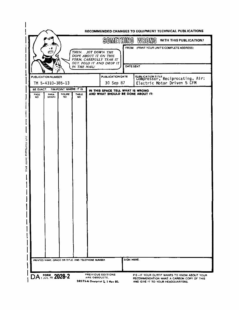


The Metric System and Equivalents
Linear Measure Liquid Measure1 centimeter = 10 millimeters = .39 inch 1 centiliter = 10 milliliters = .34 fl. ounce1 decimeter = 10 centimeters = 3.94 inches 1 deciliter = 10 centiliters = 3.38 fl. ounces1 meter = 10 decimeters = 39.37 inches 1 liter = 10 deciliters = 33.81 fl. ounces1 dekameter = 10 meters = 32.8 feet 1 dekaliter = 10 liters = 2.64 gallonsI hectometer = 10 dekameters = 328.08 feet 1 hectoliter = 10 dekaliters = 26.42 gallons1 kilometer = 10 hectometers = 3.280.8 feet 1 kiloliter = 10 hectoliters = 264.18 gallons
Weights Square Measure1 centigram = 10 milligrams = .15 grain 1 sq. centimeter = 100 sq. millimeters = .155 sq. inch1 decigram = 10 centigrams = 1.54 grains 1 sq. decimeter = 100 sq. centimeters = 15.5 sq. inchesI gram = 10 decigrams = .035 ounce 1 sq. meter (centare) = 100 sq. decimeters = 10.76 sq. feet1 dekagram = 10 grams = .35 ounce 1 sq. dekameter (are) = 100 sq. meters = 1.076.4 sq. feet1 hectogram = 10 dekagrams = 3.52 ounces 1 sq. hectometer (hectare) = 100 sq. dekameters = 2.47 acres1 kilogram = 10 hectograms = 2.2 pounds 1 sq. kilometer = 100 sq. hectometers = .386 sq. mile1 quintal = 100 kilograms = 220.46 pounds1 metric ton = 10 quintals = 1.1 short tons Cubic Measure
1 cu. centimeter = 1000 cu. millimeters = .06 cu. inch1 cu. decimeter = 1000 cu. centimeters = 61.02 cu. inches1 cu. meter = 1000 cu. decimeters = 35.31 feet
Approximate Conversion Factors
To change To Multiply by To change To Multiply byinches centimeters 2.540 ounce-inches newton-meters .007062feet meters .305 centimeters inches .394yards meters .914 meters feet 3.280miles kilometers 1.609 meters yards 1.094square inches square centimeters 6.451 kilometers miles .621square feet square meters .093 square centimeters square inches .155square yards square meters .836 square meters square feet 10.764square miles square kilometers 2.590 square meters square yards 1.196acres square hectometers .405 square kilometers square miles .386cubic feet cubic meters .028 square hectometers acres 2.471cubic yards cubic meters .765 cubic meters cubic feet 35.315fluid ounces milliliters 29.573 cubic meters cubic yards 1.308pints liters .473 milliliters fluid ounces .034quarts liters .946 liters pints 2.113gallons liters 3.785 liters quarts 1.057ounces grams 28.349 liters gallons .264pounds kilograms .454 grams ounces .035short tons metric tons .907 kilograms pounds 2.205pound-feet newton-meters 1.356 metric tons short tons 1.102pound-inches newton-meters .11296
Temperature (Exact)
°F Fahrenheit 5/9 (after Celsius °Ctemperature subtracting 32) temperature

PIN: 063090-000

This fine document...
Was brought to you by me:
Liberated Manuals -- free army and government manuals
Why do I do it? I am tired of sleazy CD-ROM sellers, who take publicly available information, slap “watermarks” and other junk on it, and sell it. Those masters of search engine manipulation make sure that their sites that sell free information, come up first in search engines. They did not create it... They did not even scan it... Why should they get your money? Why are not letting you give those free manuals to your friends?
I am setting this document FREE. This document was made by the US Government and is NOT protected by Copyright. Feel free to share, republish, sell and so on.
I am not asking you for donations, fees or handouts. If you can, please provide a link to liberatedmanuals.com, so that free manuals come up first in search engines:
<A HREF=http://www.liberatedmanuals.com/>Free Military and Government Manuals</A>
– SincerelyIgor Chudovhttp://igor.chudov.com/
– Chicago Machinery Movers