TM 5-3895-353-14&P
239
TM 5-3895-353-14&P TECHNICAL MANUAL OPERATOR, ORGANIZATIONAL DIRECT SUPPORT AND GENERAL SUPPORT MAINTENANCE MANUAL Including Repair Parts Information and Supplementary Operating, Maintenance and Repair Parts Instructions FOR ROLLER, VIBRATORY, SELF-PROPELLED (CCE) MODEL SP-848 NSN 3895-01-075-2823 HEADQUARTERS, DEPARTMENT OF THE ARMY 24 APRIL 1981
Transcript of TM 5-3895-353-14&P

TM 5-3895-353-14&P
TECHNICAL MANUAL
OPERATOR, ORGANIZATIONALDIRECT SUPPORT AND GENERAL SUPPORT
MAINTENANCE MANUAL
Including Repair Parts Informationand
Supplementary Operating, Maintenanceand Repair Parts Instructions
FOR
ROLLER, VIBRATORY,
SELF-PROPELLED
(CCE) MODEL SP-848
NSN 3895-01-075-2823
HEADQUARTERS, DEPARTMENT OF THE ARMY
24 APRIL 1981

This manual contains copyright material and is published with permissionof Rexnord Inc. and Detroit Diesel Allison, Division of General Motors Corporation.
TM 5-3895-353-14&P
TECHNICAL MANUAL HEADQUARTERSDEPARTMENT OF THE ARMY
No 5-3895-353-14&P WASHINGTON, DC 24 April 1981
OPERATOR, ORGANIZATIONAL, DIRECT SUPPORT
AND GENERAL SUPPORT MAINTENANCE MANUAL
INCLUDING REPAIR PARTS INFORMATION AND
SUPPLEMENTAL MAINTENANCE AND REPAIR
PARTS INSTRUCTIONS)
FOR
ROLLER, VIBRATORY, SELF PROPELLED
(CCE) MODEL SP-848
NSN 3895-01-075-2823
REPORTING OF ERRORSYou can help improve this manual by calling attention to errors and byrecommending improvements and by stating your reasons for therecommendations. Your letter, DA Form 2028 (Recommended Changes toPublications and Blank Forms) or DA Form 2028-2 located in the back of thismanual should be mailed directly to Commander, US Army Tank-AutomotiveMateriel Readiness Command, ATTN: DRSTA-MBS, Warren MI 48090. A replywill be furnished direct to you.
SECTION I. OPERATION MAINTENANCE
II. REPAIR PARTS
III. REPAIR PARTS FOR ENGINE ASSEMBLY
IV. SUPPLEMENTAL OPERATING, MAINTENANCE AND REPAIR PARTS INSTRUCTIONS
AUTHENTICATION STATEMENTThis technical manual is an authentication of the manufacturers' commercialliterature and does not conform with the format and content specified in AR 310-3,Military Publications. This technical manual does, however, contain availableinformation that is essential to the operation and maintenance of the equipment.
}

SECTION I
OPERATION MAINTENANCE
FOR
SELF-PROPELLED VIBRATORY ROLLERS
REGISTRATION NUMBERS UBOOFL TO UBOOHF
SP 848
NSN 3895-01-075-2823

INDEX
Page
Application and Trouble Shooting (Also see pages 9 and 10) .........................................................................11, 12
Cylinder, Steering ................................................................................................................................................16Cable Clips ..........................................................................................................................................................40Cooling System, Engine .......................................................................................................................................75
Differential "No Spin" ...............................................................................................................................69 thru 74Drive Motor, Hyd......................................................................................................................................23 thru 29Draining and Filling Hyd Oil System.....................................................................................................................75
End Yoke Installation .....................................................................................................................................17, 18
Flange, Companion, Installation .....................................................................................................................17, 18Frequency Meter, Trouble Shooting .....................................................................................................................37Filtering System, Hyd Oil ...............................................................................................................................63, 64
Hydraulic System, General.............................................................................................................................13, 14Hoses, Hydraulic ..................................................................................................................................................40Hydraulic Pumps and Motors (Sundstrand).............................................................................................. 41 thru 60
Instruction Plates and Labels..............................................................................................................................4, 5Information, General ..........................................................................................................................................6, 7Isolator (Tire) Removal, Repair ......................................................................................................................30, 31
Lock Link, Steering...............................................................................................................................................10Lubrication ...........................................................................................................................................................76
Machine Preparation ............................................................................................................................................. 8
Operation (Also see pages 11 and 12)..............................................................................................................9, 10
Parts Ordering....................................................................................................................................................... 2Pump, Steering ................................................................................................................................... 19, 20, 21,22Roll Removal, Repair ......................................................................................................................... 32, 33, 34, 35
Safety Rules ......................................................................................................................................................... 3Start-Up Procedure, Transmission, Hyd ..........................................................................................................61,62
Tire Pressures......................................................................................................................................................75
Vibration Frequency Adjustment...........................................................................................................................15Vibration Meter Trouble Shooting .........................................................................................................................36
Warranty ............................................................................................................................................................... 2Wiring Diagram, Frequency Meter........................................................................................................................65Wiring Diagram, Horn ..........................................................................................................................................66Wiring Diagram, Lighting System.........................................................................................................................67Wiring Diagram, Machine.....................................................................................................................................68
1

IMPORTANT
The instrument panel is provided with protective covers for use during periods of inactivity and shifted with eyelets for alocking device. The fuel tank filler cap is also fitted with eyelets. It is recommended that locks be used on these items, ifdeemed necessary, to prevent damage or vandalism.
SERVICE
When ordering repair parts or requesting service for the Vibratory Roller, always furnish the Machine Serial Number withyour request.
Consult Milwaukee Service Department for instructions pertaining to the return of "Sundstrand" hydrostatic pumps andmotors.
2

GENERAL SAFETY RULES
Read this manual before operation. Your safety and the safety of those around you depends upon your using care andgood judgment in the operation and maintenance of this machine. Know the positions and functions of all controls beforeattempting to operate.All equipment has limitations. Understand the speed, hydrodynamic braking, steering, stability, and characteristics of themachine in a safe area before starting to work. The following are general safety comments that apply to this equipment.Review them.Avoid loose clothing, particularly cuffs and scarfs.Know what safety equipment Is required and use it. A hard hat, safety glasses, reflector type vest, and respirators are thetypes of equipment you may need.Know any hand signals that may be used and who is responsible for signalingIf you are roading the machine, know what warnings must be placed on the machine and if you will have an escortWarn all personnel who may be servicing or in the path of the machine.Correct or report any apparent machine defects.Check to see that any guards, etc. are secure and in place.Note any hazards or obstructions that may be encountered such as ditches, overhead wires, blocks, etc.Keep deck floor clean, which otherwise may become cluttered or slippery. Keep steps and grab handles free of oil andgrease.Insure proper ventilation if starting indoors.Be particularly careful If this is not the machine you would normally operate.Never leave machine unattended with engine running.Park in a clear authorized area and set parking brake before dismounting. Use and lock protective operating counselcovers.Secure all caps and filler plugs for fuel, oil, hydraulic fluid, battery covers and radiator.Know levels for engine coolant, lubricating oil, and fuel tank.Secure and lock seat Use safety belt, if required.Always place controls in neutral and lock parking brake before starting.Test steering, right and left, while moving slowly.Test hydrodynamic braking while moving slowly.Listen to engine and transmission while moving slowly to determine any unusual noises.Report any defect in machine noted during operation.Observe instruments and gauges frequently.Do not permit riders on machine.Know and observe any traffic flow patterns on your job and obey flagman, road signs or signals.Do not adjust machine with engine running.Do not open any hydraulic lines that are under pressure or too hot to touch.Do not smoke while in the process of refueling.Lock steering lock link when working on machine.
3

4

FIGURE 1
5

GENERAL:
Vibratory compaction is the art of densifying or increasing the unit weight of a material mass through the application ofdynamic forces, with the expulsion of air and in some cases moisture The extent to which a material can be compacteddepends on the characteristics of the particular material, the amount of force used to compact it, and the moisturecontent of that particular material.
Compaction is necessary in order to form a stable foundation for any structure in which a future decrease in volume ofthe material will be detrimental. This covers highways, buildings, and other structures However, there are actually twopurposes to compaction, one is to consolidate material to avoid future settlement, while the other is to build strength Intothe material
The theories advanced on vibratory compaction are numerous; and in many cases varied However, it appears that themost efficient compaction by vibration occurs at or near the material resonance point These resonance points varyamong material types with the range of 1200 to 1800 vibrations per minute covering most of the materials In whichvibratory rollers are effective Functionally vibratory compaction is the inter- relationship of three factors frequency,amplitude, and force. Frequency is the number of vibrations per minute while amplitude Indicates the vertical distancethe vibrating roll travels from a theoretical center to its maximum distance from this center Total vertical movement istechnically double-amplitude, although in some cases may be referred to simply as amplitude. Amplitude is greatestwhen the roll is vibrating at material resonance.
Vibratory force is usually generated by a rotating eccentric weight Although this centrifugal force acts radially In alldirections from the center of the roll, only the vertical or near vertical components are used to compact.
Vibratory compaction is suited to granular type soils and in these materials will give excellent compaction resultsVibratory rollers are basically a deep type of compactor in soil, that is, they can compact deep lifts Smooth roll may,vlbratories however, leave the top inch of the surface loose in granular soils This is generally attributed to the horizontalvibrations traveling along the soil surface This uncompacted surface can be readily compacted with the roll in a non-vibrating condition
6
FIGURE 3
FIGURE 2

The density requirement for the material to be compacted is predetermined by the engineers in the soil laboratory. Fromthese lab tests a given density standard for this material will result. Field tests will insure compaction to this standard.For trouble shooting, refer to pages 11The normal method of operation is in a "back and forth" pattern. On short runs, the shuttle method is used without turningaround. On long passes, the turn-around method may be used.Field testing the compacted area will determine the number of passes and selection of frequency required.The frequency range is listed below. Always compact in low range - 0 to 5 MPH. High range, approximately 12 to 16MPH, is used for travel only to a different site over smooth surfaces. Always stop machine and set parking brake beforechanging transmission speed range because hydrodynamic braking is inoperative when transmission is in neutral. NOTE:For ease of shifting, jog travel lever, with engine at low idle.For the first passes, use lower frequency - 1200-1500 vibrations per minute. For "tender" type soils or weak foundations,use lower frequency also - 1200-1300 vibrations per minute on first passes.Frequency (VPM) can be read on the Vibration Frequency Gauge affixed to the instrument panel. To change frequency,move the Vibration Control Lever. The further the lever is moved away from "neutral", the higher the frequency, eitherforward or reverse travel.
REX VIBRATION METER
The vibration meter measures the amplitude of roll vibration and this amplitude is indicated on the Vibration MeterGauge. The higher the meter reading, the greater the amplitude. Popular theory indicates that the maximum amplitudeoccurs at or near the point of soil resonance; and at this point of soil resonance, compaction is most efficient.Soil resonant frequency can vary with the type of soil, inherent soil moisture, and degree of compaction. Thus the soilresonant frequency can change with successive passes of the compactor.To utilize the Rex vibration meter, the operator adjusts the frequency at the beginning of the pass to maximum amplitudeby reading the highest meter indication. This will serve as a guide to obtain the most efficient operation. The vibrationmeter is especially valuable as a guide where high densities are difficult to obtain.
*FREQUENCY RANGESSP848 ...................................... 1200-1800 VPM
CAUTIONREXNORD assumes no liability for any damage due to vibrations transmitted by REX Vibratory Rollers.
This is an area that is unpredictable unless all soil and subsoil conditions are known. The manufacturer of this equipmentcan only alert the equipment operator that good judgment has to be exercised when compacting close to structures. Anyvibration propagation may have to be checked before proceeding.
7

PREPARATION OF VIBRATORY ROLLER FOR USE SP848
1 Check for shortage or damage. When the machine is received from the carrier, complete inspection for damageshould be made. Initiation of claims, if any, shortage or damage, should be made at this time. A description should bemade on the freight bill.
2 Disconnect the steering lock link (painted red) between roll frame and main frame. Refer figure 5
3. Remove any protective material that may be covering instrument panel gauges, plates, open ports, etc.
4. Battery is shipped dry. Fill with electrolyte (provided) to level. Check battery cables for tightness and proper polarity.See page76.
5. Clean off excess paint or grease from steering cylinder rod.
6. Refer to engine manual to prepare engine for running.
7 Fill engine fuel tank.
8. Prestart-up inspection.CAUTION
If roller is to be pushed or towed, the two speed transmission (shift lever) must be in neutral position
a. Check oil level in hydraulic oil reservoir (Sight gauge.)
b. Check oil level in the 2-speed transmission case See Lubrication Chart
c. Check oil level in axle differential and wheel ends. See Lubrication Chart.
d. Check air pressure in tires 23.1 x 26 diamond tread - 15 PSI (SP848)
e. Check air pressure in pneumatic Isolators - 25 PSI.
f. Grease all fittings See Lubrication Chart
g. Vibrator bearings (one each side of roller drum) requires special grease. *Fill grease gun (provided) withShell Darian EP-2 cartridges (#502-223-80) shipped with machine Lubricate two (2) vibrator bearings with ten (10)strokes of gun, each side Place gun In tool box
9. Check maximum frequency setting - both forward and reverse * Darina grease cartridges (P/N 502-223-80, 10pack)
a. Maximum frequency may be ordered from Rexnord Inc , Milwaukee SP848 - 1800 VPM
b Check maximum frequency with engine at full throttle (2450 RPM) If maximum frequency setting Is notcorrect, adjust stop screws on Sundstrand pump lever Pump is at flywheel end of engine and is accessible frombelow. See page 17.
10 Check operation of controls.
a Check neutral points - adjust below instrument panel, if necessary.
b Check operating friction Adjust cable brake, one on each cable below instrument panel. Tighten just enoughso that the control handle will hold its position.
11. Check operation of vibration meter. Gauge reading on instrument panel should generally read between "1" and"8" while vibration.
8

FIGURE 4NOTE. The instrument and control counsel shown in figure 4 is of a SP900 "Asphalt" Roller. The SP848 and SP1300"Soil" Rollers do not have items 5 and 17. Also for the Soil Rollers, the steering wheel is located In the center of thecounsel. The SP900 has Duel Steering.
1. START BUTTON 10. FUEL GAUGE2. IGNITION KEY 11. VIBRATION METER GAUGE3 ENGINE SHUT-DOWN 12. FREQUENCY GAUGE VPM4. ENGINE THROTTLE 13. VIBRATION CONTROL LEVER5. SPRINKLER SWITCHES, WATER (SP900) 14. FORWARD-REVERSE TRAVEL LEVER6. TEMPERATURE GAUGE 15. EMERGENCY OR PARKING BRAKE7. AMMETER GAUGE 16. EXCITER ADJ. SCREWS8. ENGINE SPEED (RPM) 17. SPRINKLER SWITCH, DIESEL (SP900)9. OIL PRESSURE GAUGE 18. ACCESS CAP, BRAKE CYL FILL
OPERATION (Fig 4)
NOTE In addition to the Operation Procedure, it is suggested that the "Application and Trouble Shooting Guides" bereviewed as a "matter of operational procedures.
A. Start-Up
1. Place the Forward-Reverse Travel Lever (14) in neutral (detent position) and the Vibration Control Lever (13) inneutral (detent position) Detent is center position.
2. Turn Ignition Key (2) to "on". Press Starter Button
(1) to start and allow engine to warm up (160°-185°F operating temperature at approximately 1000 RPM . DepressEngine Throttle Button (4) and simultaneously pull handle until 1000 RPM is indicated on Indicator (8). IMPORTANT:If after two or three attempts to start and engine does not start, refer to Engine Manual under "Engine StartingInstruction".
CAUTIONEngine and hydraulic oil system must be allowed to warm up before applying load.
3. After warm-up move Engine Throttle (4) up to approximately 2400 RPM. Turning the knob of Throttle(4)9

will cause minor adjustment in RPM's If roller is to TRAVEL (not compact), place the Two-Speed Control Lever in ''highrange", located to the right and behind operator High range is for traveling only. If roller is to compact, place theTwo-Speed Control Lever in "low range".4. For compacting, move the Forward-Reverse Travel Lever (14) up to approximately 2 MPH (The 2 MPH must beestimated as compared to a "slow walk" since the machine is not equipped with a speedometer The further the lever ismoved forward, away from neutral, the faster the machine will travel )5 Engage vibrator by moving the Vibration Control Lever (13) forward away from neutral The further this lever is movedaway from neutral, the higher the vibration frequency winch can be read on the Vibration Frequency Gauge (12)5 To reverse direction - move the Vibration Control Lever (13) back to neutral. Move Forward-Reverse Lever (14) back toneutral Hydrodynamic braking will occur It is recommended not to use the Brake (15) for repeated stops as the brake isused for parking or emergency stops only7 When machine comes to a complete stop, move the Forward-Reverse Lever (14) back reversing directionMove Vibration Control Lever (13) back reversing rotation of the eccentric shaft within the steel roller. Resumecompaction.
IMPORTANT
Always move the Travel Control Lever and the Vibration Control Lever in the same direction when rolling, either forwardor reverseWith the control levers together, in either direction, the vibrator shaft should always rotate opposite the direction of travel.If it does not, reverse the high pressure hoses to the vibrator motor. To check the direction of the vibration shaft rotation,remove the right hand side cover on roll frame and the cap covering the end of vibrator shaft.
B. Shut-Down1 Return the Vibration Control Lever (13) to neutral and the Forward-Reverse Lever (14) to neutral Return EngineThrottle (4) to idle by depressing button and pushing down on lever Allow engine to cool at idle for approximately fiveminutes Pull out Engine Shut-Down Lever (3) to stop engine Turn Ignition Key (2) to "off".
FIGURE 52 Depress Parking Brake (15) Lock Connect steering lock link See figure 5 .3 When shifting the two speed lever from "low" to ''high'' or vice-versa, bring the machine to a stop and set parking brakebefore shifting (Hydrodynamic braking is inoperative when transmission is m neutral ) For ease of shifting jog travellever, with engine at low idle, while shifting.
FIGURE 6
ROLL AND TIRE SCRAPERS (Fig 6)The steel roll is equipped with two rubber scrapers which must be hand adjusted from time to time due to normal wear.Adjust scraper as required and reverse when worn for double use.Nylon, spring loaded scrapers are provided for the smooth tires. Lock scrapers back when machine is not used to rollasphalt surfaces.
10

APPLICATION AND TROUBLE SHOOTING GUIDES
1. SP848 - Used on Granular Soils or *Crushed Stone
A. Basic Information
1. Adjust vibration frequency to be "in tune" with soil.
a. Well graded soils generally use 1700-1800 vibrations per minute.
b. Tender soils (clean sand, etc.) can use vibration frequencies as low as 1300 vibrations per minute.
c. *Crushed stone generally requires 1700-1800 vibrations per minute.d. Use the vibration meter.
2. Always move the travel control lever and the vibration control lever in the same direction when rolling, eitherforward or reverse. With control levers together, in either direction, the vibrator shaft should always rotateopposite the direction of travel. If it does not, reverse the high pressure hoses to the vibrator motor. To checkdirection of vibrator shaft rotation, remove right hand side cover on roll frame and the cap covering end ofvibrator shaft.
3. Operate vibrator only when the roller is in motion.
4. Soil surface should be relatively smooth and level for best compacting results. (Use of motor grader, etc.)
5. Travel speed range of 2-4 MPH is generally most efficient. (Use low travel gear range when vibrating.)
6. Maintain suitable tire pressure for good traction. (23.1 x 26 Diamond tread tire)
a. On well graded soils - 16 PSI.
b. On sandy soils - as low as 11 PSI.
7. Use proper lift thickness for most efficient compaction.
a. The higher percentage of "binder", the thinner the lift.
8. *This vibratory roller is not designed for heavy rock compaction - for heavy rock compaction, use the RexModel SP1300.
*Consult Milwaukee Engineering Dept. for further information.
Cont'd. on page 12

B. Possible Application Problems
PROBLEM SOLUTION1. Not achieving specifieddensity
A. Frequency too high or too low - Use vibration meter or follow guide linestated above
..B. Too few passes.
C. Too many passes - density can be achieved and lost with too many passes.
D. Laboratory density is not correct.
2. Loose, rough surface A. Too high a frequency on last pass - use 1200 vibrationsafter last pass. per minute or no vibration to tighten surface.
12

HYDRAULIC SYSTEMS
1 Vibrator Control Figure 7 The vibrator control systemconsists of a positive displacement axial piston pumpcoupled to the engine flywheel, a positive displacementgear type motor coupled to the eccentric drive on theroller shaft, hydraulic lines and vibrator control on theoperator's console
2 Traction. Figure 8 The hydrostatic drive Vibratory Rollerconsists of a diesel engine for power, a variabledisplacement piston type pump which is connected to theengine crankshaft. A fixed displacement, piston typemotor is coupled to the two-speed case on the axledifferential, hydraulic lines, oil reservoir, filter, oil coolerand controls.
REFERENCE FOR FIGURE 7BNO 1 - CHARGE PRESSURE GAUGE PORTNO 2 - HIGH PRESSURE GAUGE PORT FOR
ITEM 6NO 3 - HIGH PRESSURE GAUGE PORT FOR
ITEM 5NO 4 - SHUTTLE VALVESNO 5 - HIGH PRESSURE RELIEF VALVENO 6 - HIGH PRESSURE RELIEF VALVE
FIGURE 7B
FIGURE 7A
13

The variable displacement pump has a neutral position in which no fluid is pumped to the motor. Moving the travelcontrol lever on the operator's console to either side of neutral, while the engine is running, causes oil to be pumped tothe motor, one side turning the motor in forward travel and the other side in reverse travel. The further the control lever ismoved from neutral position, the faster the Roller will travel Changing the engine throttle speed will also change theRoller speed providing the pump control lever is not in neutral position. If lever is in neutral position, the Roller will notmove.
3. Power Steering. Figure 9 . This system consists of a rotor type pump mounted to a bracket on the engine and beltdriven off the engine fan pulley, an "Orbitrol" steering unit, double acting hydraulic cylinder and suit- able hydraulic hosesTurning the steering wheel to the right causes the oil under pump pressure, through the "Orbitrol" unit, to flow to thecylinder bottom, forcing the cylinder piston rod to extend out of the cylinder and in turn forces the roll to be turned to theright Turning the steering wheel to the left causes oil to flow to the top of the cylinder, forcing the piston down, thuspulling the roll to the left
FIGURE 8
FIGURE 9
14

VIBRATION FREQUENCY ADJUSTMENT - SP848 (Figure 10)
Prior to the machine leaving the factory, the vibration frequency is adjusted and set for maximum ("A" VPM below) at fullgoverned engine throttle, in forward and reverse. This setting is made after the oil is allowed to warm up (160°-185°),usually after about one-half hour of engine warm up
If the vibration control lever Is actuated to its maximum stroke at start-up, and the oil is cold, the frequency will go ashigh as ("B" VPM below) at full engine throttle. The frequency will drop down as the oil temperature rises.
Upon receipt of a new machine and/or to recheck the maximum frequency of a machine already In use, adjustment is asfollows:
The machine must be on level ground. Set parking brake.
Place the Forward-Reverse Lever in neutral (center) and the Vibration Control Lever in neutral (center).
Start engine and allow to warm up (160°-185° operating temperature) Shut off engine. Make no adjustments with theengine running.
Figure 10. The adjusting setscrews, for frequency adjustment, with jam nuts, are located on the hydrostatic pump andcan be reached from underneath and just behind the floor board.
Again start engine and bring up to full throttle.
Move the vibration control lever to its maximum travel position forward and observe the frequency reading on the gauge.Repeat this procedure in reverse. If an adjustment is necessary, return the vibration control lever to neutral and shutdown engine. Reposition adjusting screws if necessary to obtain proper frequency In forward or reverse. ½ to 1/4 turn ofthe adjusting screw equals approximately 100 VPM. Relock adjusting screw with jam nut.
Again start engine and recheck frequency as in "A" VPM below, in both forward and reverse.
MODEL "A" FREQUENCY (WARM OIL) "B" FREQUENCY (COLD OIL)SP848--------------------------------- 1800-1825 VPM -----------------------------------1900 VPM
FIGURE 10
15

STEERING CYLINDER REPAIR (CROSS) Fig. 18
1 Clean hose connections at cylinder ends. Remove hoses and plug hose ends
2 Remove cylinder from machine. Cylinder may be gripped in a lead jawed vise at the base end.
3 Remove three bolts (A) from head cap (B) and remove head cap from cylinder tube (C) and rod (D).
4 Push head (E) into cylinder tube past retainer ring (F) Remove retainer ring. Pull entire piston rod assembly outfrom tube. Remove head (E) from rod (D).
5 Inspect Inside of tube (C), head (E), rod (D) and piston head (M) for score marks. Replace where necessary.
6 "0" ring (G) can be replaced by removing nut (H) and piston head (M). Pry out T-ring seal (J) and replace with new.Pry out "0" ring and back-up (K) from head (E) and replace with new. Replace "0" ring (L). Remove wiper seal (N) fromhead cap (B).
7 Insert piston rod assembly into cylinder tube being careful not to damage T-seal (J). Slide head (E) with new "0"ring (L) and "0" ring with back-up (K) into tube and onto rod far enough to install retainer ring (F) In- stall retainer ring
8 Pull piston rod assembly out and against head (E)to force head against retainer ring. Slip head cap (B) onto rodand into tube. Line up holes, insert bolts (A) and tighten Install new wiper seal (N)
9 Reinstall cylinder on machine. Connect hoses. Purge air from cylinder by actuating cylinder under power. Re-place lost oil.
16

INSTALLING THE COMPANION FLANGE (Fig. 19) OR END YOKE (Fig.20 ) ON THE TAPERED SHAFT OF"SUNDSTRAND" HYDROSTATIC PUMP.
The companion flange or end yoke Is assembled onto the tapered pump shaft with a woodruff key, slotted nut and cotterpin.
A minimum torque must be applied to the slotted nut to prevent movement of either the companion flange or end yokeon the pump shaft.
Clean pump shaft and companion flange or end yoke with a solvent. Remove any burrs from key or keyways that may bepresent.
Assemble companion flange or end yoke on pump shaft making certain key is lined up with keyway. Use a short brassrod or lead mallet to lightly tap the flange or yoke end on pump shaft so the tapered mating surfaces are in contact beforeapplying torque to the slotted nut.
Thread on slotted nut. Torque nut to the following ft lbs minimum, then insert cotter pin. Do not back off on slotted nut toattempt to insert cotter
"22" and "23" series pump. Dry threads - 230 ft. LbsOiled threads - 185 ft lbs
Apply a coating of oil or grease to the splines of the yoke shaft. Grease fittings on journals.
17

FIGURE 20
18

FIGURE 21
VTM42 STEERING PUMP
The assembly and construction of the VTM42 steeringpump is illustrated in cutaway Fig 21 The unit consists ofthe body, cover, ring, rotor, vanes, pressure plate, reliefvalve, and drive shaft assembly.The pump is equipped with Integral flow control and reliefvalves. Volume greater than the rated flow is by-passedto the inlet, within the pump through action of the flowcontrol valve which operates on a pressure differential Therelief valve limits the maximum pressure m the hydrauliccircuit.It is important that the hydraulic pump drive belt bemaintained tight to prevent slipping to maintain maximumoutput of pump. The pump bracket is provided withslotted holes by which the pump may be moved upward totighten the drive belt.Operation - Reference Fig. 21, the rotor is driven withinthe cartridge by a drive shaft, coupled to a power source.As the rotor speed increases, centrifugal action causes thevanes to follow the cam-shaped contour of the pump ring(Fig. 22) System pressure fed behind the vanes assuressealing contact of the vanes on the ring cam contourduring normal operation.The ring is shaped so that two opposing pumpingchambers are formed, thus canceling any hydraulic loadson the bearings Radial movement of the vanes, androtation of the rotor, causes the chamber area betweenvanes to increase in size at the inlet (large diameter)section of the ring This results in a low pressure, orvacuum in the chamber. This pressure differential causesoil to flow into the inlet, where it is trapped between therotating vanes and is forced, through porting in thepressure plate to discharge into the system as thechamber size decreases at the pressure (small diameter)section of the ring.
The flow of oil developed by pump operation is controlledby the integral flow control and relief valve.NOTE Relief valve - an integral relief valve in the unitprotects the pump and other units in the hydraulic systemfrom excessive pressures. Relief valve adjustment - therelief valve is pre-set at the factory and no field adjustmentshould be made If the relief valve setting must bechanged, a replacement valve should be installed
The flow control valve functions to bypass excess oil intoa return circuit through an internal passage in the pumpcover. The bypassed oil Is directed into the pump inlet.The high velocity of this oil accelerates flow from the tankThis combination produces a super-charge at the inlet ofthe pump.When excessive pressure develops in the hydraulicsystem, the relief valve unseats, causing the flow controlvalve to open and bypass the entire pump output. Thislimits maximum pressure in the system to the relief valvesetting and protects circuit components A portion of theoil bypassed under pressure relief conditions is returned tothe reservoir to improve heat dissipation.Normally, the pump requires no manual priming.However, It is essential that, after starting a minimumdrive speed of 400 r p m. be held until the pump picks upIts prime and pressure is built up in the system. Failure toobserve the above precaution can result in scoring andpossible seizure of the pump due to a lack of oil forlubrication.CAUTION: Do not use hydraulic brake fluid. Use only therecommended oil.
For Trouble Chart refer to chart on page 26.
VTM42 PUMP OVERHAUL
A. DISASSEMBLY - Before removing pump - be sure itis not under pressure.
1. A puller must be used to remove pulley from shaft,otherwise bearing and shaft damage may result.During disassembly, special attention should be givento identification of parts for proper reassembly.Clean all parts except "O" ring seals in a cleanmineral solvent. After drying thoroughly, lay the partson a clean, lint free surface. All internal oil passagesof the pump cover, housing and body must bethoroughly cleaned.CAUTION Never use an air hose on or near theexposed parts because of the presence of water anddirt In the air system.
All "0" rings, and the shaft seal should be replaced atreassembly. All seals should be soaked in hydraulicfluid before being used. Refer Fig. 23 and proceedwith disassembly.
19
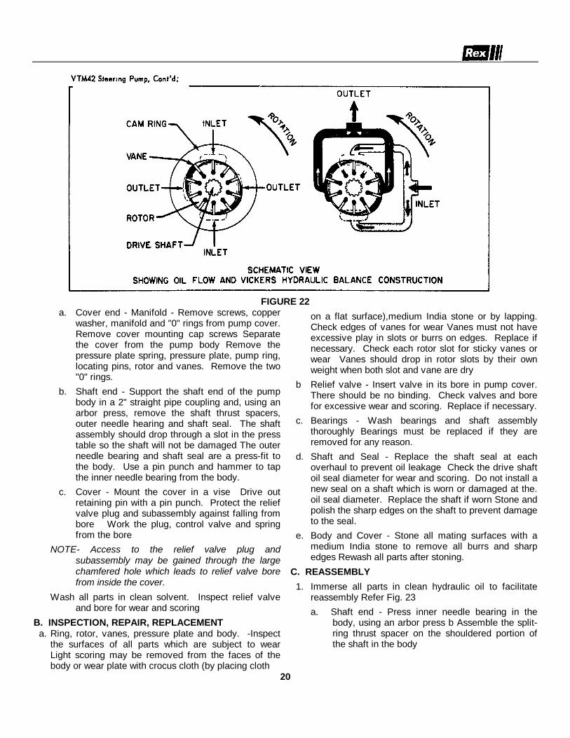
FIGURE 22a. Cover end - Manifold - Remove screws, copper
washer, manifold and "0" rings from pump cover.Remove cover mounting cap screws Separatethe cover from the pump body Remove thepressure plate spring, pressure plate, pump ring,locating pins, rotor and vanes. Remove the two"0" rings.
b. Shaft end - Support the shaft end of the pumpbody in a 2" straight pipe coupling and, using anarbor press, remove the shaft thrust spacers,outer needle hearing and shaft seal. The shaftassembly should drop through a slot in the presstable so the shaft will not be damaged The outerneedle bearing and shaft seal are a press-fit tothe body. Use a pin punch and hammer to tapthe inner needle bearing from the body.
c. Cover - Mount the cover in a vise Drive outretaining pin with a pin punch. Protect the reliefvalve plug and subassembly against falling frombore Work the plug, control valve and springfrom the bore
NOTE- Access to the relief valve plug andsubassembly may be gained through the largechamfered hole which leads to relief valve borefrom inside the cover.
Wash all parts in clean solvent. Inspect relief valveand bore for wear and scoring
B. INSPECTION, REPAIR, REPLACEMENT a. Ring, rotor, vanes, pressure plate and body. -Inspect
the surfaces of all parts which are subject to wearLight scoring may be removed from the faces of thebody or wear plate with crocus cloth (by placing cloth
on a flat surface),medium India stone or by lapping.Check edges of vanes for wear Vanes must not haveexcessive play in slots or burrs on edges. Replace ifnecessary. Check each rotor slot for sticky vanes orwear Vanes should drop in rotor slots by their ownweight when both slot and vane are dry
b Relief valve - Insert valve in its bore in pump cover.There should be no binding. Check valves and borefor excessive wear and scoring. Replace if necessary.
c. Bearings - Wash bearings and shaft assemblythoroughly Bearings must be replaced if they areremoved for any reason.
d. Shaft and Seal - Replace the shaft seal at eachoverhaul to prevent oil leakage Check the drive shaftoil seal diameter for wear and scoring. Do not install anew seal on a shaft which is worn or damaged at the.oil seal diameter. Replace the shaft if worn Stone andpolish the sharp edges on the shaft to prevent damageto the seal.
e. Body and Cover - Stone all mating surfaces with amedium India stone to remove all burrs and sharpedges Rewash all parts after stoning.
C. REASSEMBLY
1. Immerse all parts in clean hydraulic oil to facilitatereassembly Refer Fig. 23a. Shaft end - Press inner needle bearing in the
body, using an arbor press b Assemble the split-ring thrust spacer on the shouldered portion ofthe shaft in the body
20

FIGURE 23
c. Press outer needle bearing onto shaft. The edgeof the bearing must be 1/64” below the shaft sealshoulder when assembled This provides for shaftend play of approximately .010" to .15".
NOTE: Tools for installing bearings can be made fromround stock, the outside diameter of which is slightlysmaller than the outside diameter of the bearing and theinside diameter slightly larger than the shaft diameter Donot score or otherwise damage the shaft during thisoperation.
d. Position the seal on the shaft end body, beingcareful not to damage seal. Press seal in until itengages the shoulder in the body. This shoulderacts as a positive stop for the seal. Do notoverpress as damage to the seal will result.
e. Cover end - Install locating pins in pump body.Install ring over pins in correct direction ofrotation.Install rotor with chamfered edge of splined hole"in" or toward pump body. The chamferfacilitates assembly.Install vanes with their radius edge toward theinner ring contour.Oil the cartridge with clean hydraulic oil andinstall pressure plateInstall "O" rings. Install pressure plate spring andcover Tighten cover screws to 25-30 lbs ft.torque.
Install pressure compensating spring in reliefvalve bore. Insert valve assembly with thehexagonal end toward the spring. Install plugwith "0" ring in bore and hold it in position whiledriving a new retaining pin.
f. Manifold - Install "0O" rings in pump cover andsecure manifold to pump body with screws.Copper washer is used on screw where tappedhole enters oil passage.
21

TROUBLE SHOOTING CHART(VTM42 STEERING PUMP)
TROUBLE PROBABLE CAUSE REMEDY
Pump Not Delivering Oil. Driven in wrong direction ofrotation.
Check direction of pump shaft rotation. It should rotateclockwise as viewed from the coupling end of the unit.
See also reassembly instructions for pump cartridge.
Pump drive shaftdisengaged or sheared.
Remove pump. Determine damage to cartridge parts (seedisassembly instructions). Replace sheared shaft andneeded parts.
Flow control valve stuckopen.
Disassemble pump and wash control valve in a cleansolvent. Return valves to its bore and slide it back and forth.No stickiness in movement should occur. If a gritty feeling isnoted on the valve O.D. it may be polished with a crocuscloth. Avoid removal of excess material or rounding of valveedges during this operation. Do not attempt to polish thevalve bore. Wash all parts before reassembly of pump. Fillsystem with clean oil as recommended.
Vane or Vanes stick in slots. Disassemble pump. Examine rotor slots for dirt, grime orsmall metal chips. Clean rotor and vanes in a good gradesolvent (mineral oil or kerosene). Reassemble parts andcheck for free vane movement.
Oil viscosity too heavy topick up prime.
Use fluid of the proper viscosity as recommended in oil data(Table).
Noisy Pump Operation. Pump intake partiallyblocked.
Drain system completely. Flush to clear pump passages.Flush and refill system with clean oil as recommended.
Air vent for oil tank cloggedor dirty strainer.
Remove filler cap and clean air vent slot. Check strainer intank for clogged condition. Drain, flush and add clean oil tosystem.
Air being drawn into pumpreturn connection.
Pump must receive air-free oil or pump will be noisy. Drainsystem. Tighten all hose connections. Clean or replacefilter. Add clean oil as recommended.
Leaky shaft seal. Check pump shaft seal and replace if sealing lip has beendamaged. Check for scoring of shaft at seal contact area.Replace faulty shaft.
22

HYDRAULIC (VIBRATOR) DRIVE MOTOR MODEL P51.
Units should be thoroughly cleaned with a solvent beforeremoving from the machine. Plug hose ends afterdisconnecting from motor.
Plug 5 in position B gives clockwise rotation.
Plug 5 In position A gives counterclockwise rotation.
Check valves in both positions give bi-directional rotation.
PARTS LIST
1. Snap Ring 11. Gasket Seals2. Outboard Bearing 12. Gear Housing3. Seal 17. Port End Cover4. Shaft End Cover 18. Washers5. Check Assemblies or 19. Cap Screws
Plug 20. Nuts6. Ring Seals7. Roller Bearings8. Pocket Seals9. Thrust Plates
10. Integral Drive Shaftand Gear Set
23

GEAR HOUSINGS:Wear in excess of 005" cut-out necessitates replacementof the gear housing.Place a straight-edge across bore If you can slip a 005"feeler gauge under the straight-edge In the cut-out area,replace the gear housing.Pressure pushes the gears against the housing on the lowpressure side As the hubs and bearings wear, the cut-outbecomes more pronounced Excessive cut-out. In a shortperiod of time Indicates excessive pressure or oilcontamination If the relief valve settings are withinprescribed limits, check for shock pressures or tamperingWithdraw oil sample and check it and tank for dirt.Where cut-out is moderate, 005" or less, gear housing Is ingood condition, and both parts are of the same size,housing may be flopped over and reused
GEARS
Any wear on gear hubs detectable by touch, or in excess of002" necessitates replacement Scoring, grooving, orburring of outside diameter of teeth requires replacementNicking, grooving, or fretting of teeth surfaces alsonecessitates replacement.
DRIVE SHAFTS
Replace if there is any wear detectable by touch in the sealareas or at the drive coupling 002" wear is the maximumallowable.Wear in the shaft seal areas indicates oil contaminationWear or damage to splines, keys, or keyways necessitatesreplacement.
BEARINGSIf gears are replaced, bearings must be replaced Bearingsshould fit Into bore with a light press fit. A neat hand fit isallowable If bearings can fall out, bore may be oversize.
SEALS AND GASKETSReplace all rubber and polymer seals wheneverdisassembling pump Include all "0" rings, pocket sealsbehind thrust plates, shaft seal, and gasket seals.
CHECK VALVESExamine small check valves In shaft end cover to makesure they are Intact and functioning If there are no checkvalves here, make sure the high pressure side of the shaftend cover is plugged with an Allen plug.
THRUST PLATESThe thrust plates seal the gear section at the sides of thegears Wear here will allow Internal slippage, that is, oil willbypass within the pump.002" maximum wear is allowable Replace thrust plates ifthey are scored, eroded, or pittedCheck center of thrust plate where the gears mesh.Erosion here indicates oil contamination.Pitted thrust plates indicate cavitation or oil aeration.Discolored thrust plates indicate overheating, probablyinsufficient oil.
24

DISASSEMBLY
25

DISASSEMBLY, Cont'd.
26

ASSEMBLY
27
ASSEMBLY, Cont'd.
28

ASSEMBLY, Cont'd.
29

PNEUMATIC ISOLATOR (TIRE AND WHEEL) REMOVALFOR REPAIR OR CHANGE (Figures 21 thru 27)The pneumatic Isolators (tire and wheel) can be removedwithout removing the roller from the roller frame. For thepurpose of describing the roller sides - the hydraulic motorside is the drive end and the opposite side is the drivenend.Repair should be made on a hard level surface. As asafety measure, wedge block the traction tires, front andback. Connect the steering lock link1. Figure 21 Remove the roller frame side covers at the
drive and driven ends2. Figure 21 Place hydraulic jacks or blocking under the
front and rear ends of the roller side frame beingrepaired, where indicated with arrows. Apply justenough upward pressure to keep the frame fromlowering
3. Deflate pneumatic Isolator (tire) at opposite side beingrepaired to approximately 10 PSI (presuming the tirebeing repaired is already deflated) This is to acquireas much end play as possible to accomplish step 7
FIGURE 21
4. Figures 22 and 23 Drive End Remove the hoseclamp holding the two high pressure hoses in place.Loosen slightly (but do not remove the two hydraulic elbowfittings (3) threaded into motor). Remove four cap screws(4) holding the motor to the motor and wheel mount Pulland swing out the motor from mounting frame.
5. Figure 23 Remove two cap screws (6), one eachside, holding Isolator cover half to roller frame. Removefour cap screws (7), two each side, holding the upper andlower cover halves together, then remove upper cover half
6. Refer figure 22. Remove six cap screws (5)
FIGURE 22
FIGURE 23
7. Figure 26 Using a sizable pry bar, place pry barbetween roller frame and edge of roller on the sidebeing repaired and pry to force the roller frame awayfrom the roller as far as possible. This will permitmore clearance to remove the isolator.
8. Manipulate the Isolator up and out from the rollerframe NOTE The tire is keywayed to fit the keywelded to the upper isolator half In reassembly thekeyway in tire must line up and fit the key in isolator.
9. Repair or change tire in the conventional manner10. Clean and inspect the interior of the isolator halves.
After inspection, should the non-slip material be looseor damaged, it should be replaced with new Interiorsurfaces must be cleaned with a solvent and drybefore application of new non-slip material.
11. Assembly is in reverse of above Add hydraulic oil toreservoir as a result of oil lost at loose motorconnections.
30
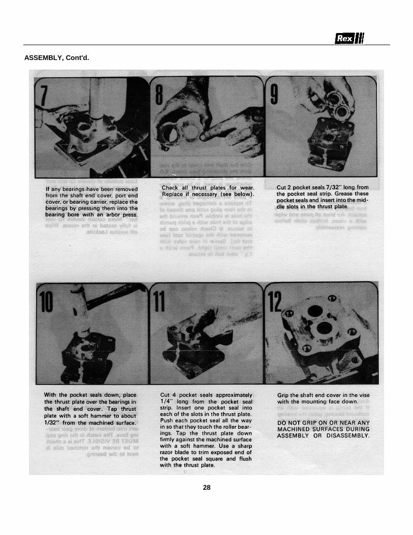
Driven End - Figure 24 and reference figure 21.
12. Follow steps 1 thru 3.
13. Figure 24. Back off on lock nut holding magneticpick-up (8) into the bearing housing. Unthreadmagnetic pick-up out of bearing housing and tuckinto roller frame. If machine is not equipped with anamplitude indicator, proceed with step 15.
FIGURE 24
FIGURE 25
14. Figure 25. If machine is equipped with an amplitudeindicator, remove top pin (X) and drop mechanisminto roller frame. Remove two wheel bolts (W) andremove bracket (Z).
15. Figure 24. Remove four bolts (9) holding bearingflange to wheel mount and remove flange. Removeremaining wheel bolts (10).
FIGURE 26
16. Follow step 5 and reference figure 23.
17. Follow steps 7 thru 11.
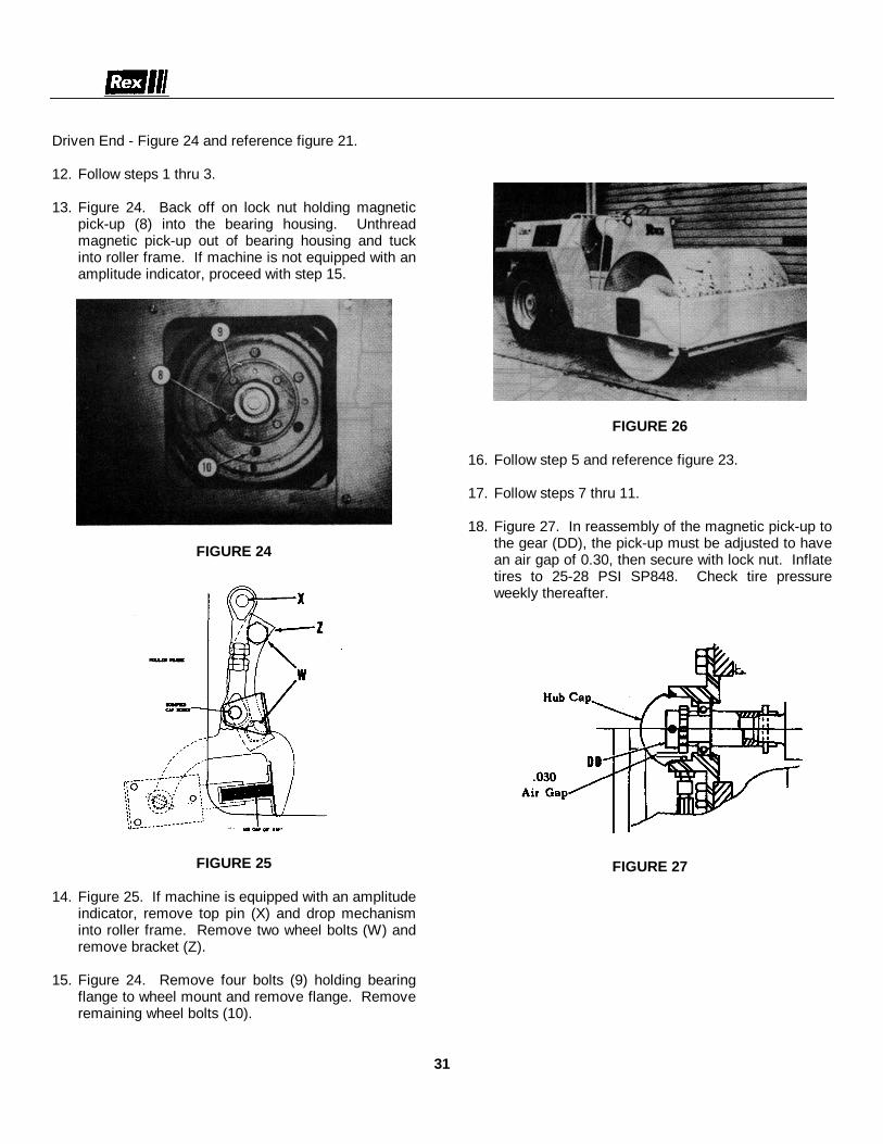
18. Figure 27. In reassembly of the magnetic pick-up tothe gear (DD), the pick-up must be adjusted to havean air gap of 0.30, then secure with lock nut. Inflatetires to 25-28 PSI SP848. Check tire pressureweekly thereafter.
FIGURE 27
31

FIGURE 28
32

A. ROLLER AND ISOLATOR (TIRE) REMOVAL FORACCESS TO VIBRATOR SHAFT BEARINGS ANDSEALS (Fig. 28). ALSO REFER FOLLOWING "STEPB".
The roller should be in a machine shop or garage on ahard level surface. Wedge block the traction wheels asa safety precaution. Connect the steering lock link.1. Place blocking, each side, between bottom of roll
frame and floor to retain roll frame from falling when rollis disconnected and moved away from roll frame.2. Remove roll frame side covers, each side.3. Remove four bolts, two each side, from inside ends
of front frame holding front frame to main frame. A forklift or lifting device should support the front frame duringremoval. Move front frame out away from roll.4. Hydraulic Motor Side - Clean hydraulic hose fittings
and motor with solvent and blow air dry beforeproceeding. Disconnect hydraulic hoses from motor.Plug hose ends and hydraulic motor port holes to keepdirt from entering.5. Remove four ½ " x 1½ " cap screws (A) holding
motor to wheel and motor mount flange (V) and removemotor.6. Four bolts hold the isolator halves (B) to the roll
frame, two on top and two on the bottom. Removethese bolts. This will free the roll assembly from themain frame on this side.7. Opposite Hydraulic Motor Side - Disconnect
connector (Y) and fold cord back into roll frame. Referto insert "AA", disconnect rod end linkage (X), thenremove two bolts (W) and remove bracket (Z).8. Four bolts hold the isolator halves (B) to the roll
frame, two on top and two on the bottom. Removethese bolts. This will free roll assembly on this side.9. Move roll assembly forward through frame opening.10. If both side isolator housings (B) are to be removed,remove eight bolts, four each side, holding isolatorhousing halves together, exposing the pneumaticisolators.11. Remove twelve bolts (D), six each side, holdingwheel to wheel flange (V), and remove wheel andisolator. Isolators may now be repaired or replaced inthe conventional manner.12. In reassembly, inflate pneumatic isolators toapproximately 5 p.s.i. Bolt wheel back on wheel flange.Bolt isolator halves together, then inflate and maintainisolators to 25 p.s.i. *See Note belowNOTE: The selection of the pneumatic isolators is theresult of an extensive test program in order to attainmaximum vibration isolation. It is therefore imperativethat should replacement be necessary, the isolator bereplaced by REX part numbers 2986035-68 isolator and
298-6036-68 tube.13. Remaining reassembly is in reverse of above.
Add hydraulic oil to tank to level indicated. Run unit topurge air from system. Recheck oil level. Add oil ifnecessary.
*Clean interior of isolator halves before reassembly.When interior of isolator halves are cleaned andinspection indicates that the 3-M non-slip material isloose or damaged, it should be replaced with new.Metal surfaces should be cleaned with a solvent and drybefore application of new material.
B. VIBRATOR SHAFT BEARING AND SEALREPLACEMENT (Fig. 28)To inspect, repair or replace the shaft bearings andseals the following disassembly procedure isrecommended.1. Remove roll from frame as outlined under
"Pneumatic Isolator Removal."2. With wheels (isolator rims) removed, next remove
eight 3%" x 3" cap screws (C), each side, holding rollhub (E) to roll head.3. Remove inspection plates, each side.4. Remove lubrication hoses from each roll hub (E).5. Insert four of cap screws (C) into the tapped holes in
the driven hub (E) (DRIVEN END). Tighten boltsevenly. This will jack the entire vibrator shaft assemblyout of roll toward driven end.CAUTION and NOTE: During removal, support the driveend of shaft assembly thru inspection opening (driveend) in roll head. After removal, the shaft assembly canbe placed on "horses" for ease of working.Shaft Parts Disassembly, Drive End.Drive Coupling - Removal and Reassembly. Ref. Figs.28 and 29.6. Remove outer internal snap ring (A), then slide outsplined coupling half (B) with seal (C).7. Remove nut and washer (D) from vibrator shaft.
FIGURE 29
33

8. To remove the driven coupling half (E). A pullermay easily be made from bar stock, figure 30 below orordered from Rexnord per part number 102-8419-1.Place puller in hub of coupling half (E), figure 31. Inserttwo 5/16 - 18 x 2 ½ “ long cap screws thru the 3/8” dia.Holes in puller and thread into tapped holes in couplinghalf. Thread the ½ ” - 13 x 3” sq. hd. cone point setscrew in to tapped hole of puller. Tighten down againstshaft to remove coupling half. If necessary give a sharpblow to set screw to unseat coupling from tapered shaft.Remove puller from coupling half.
FIGURE 30
9. Remove snap ring (F) and seals (G) and (C).Inspect all parts for wear and/or damage, especially thesplines of coupling halves and sleeve (H). New sealsshould be used and soaked in oil before reassembly. Ifnew coupling halves and sleeve are used make sure allparts are free of burrs. Proceed with Step 14 for further“drive end” disassembly. If not proceed with Step 10 toassemble coupling.
FIGURE 3110. In reassembly, install new seal (G) on drivencoupling (E) first. Slip on coupling sleeve (H) and lockin place with snap ring (F). Install this assembly onshaft with key (J). Make sure coupling is seatedproperly on
shaft. Tap coupling with wood block or brass rod withhammer if necessary to assure complete seating.11. Install washer and nut (D)Torque nut to 250-275 ft.lbs.12. Hand pack this assembly with Mobilgrease 77 (orequivalent) before proceeding.13. Install drive coupling (B) with new seal (C) intosleeve. Lock in place with snap ring (A).NOTE: The drive coupling assembly must be handpacked with new and clean grease monthly. Refer toLubrication Chart.14. (Fig. 28) Remove four 3/" x 1" flat head machinescrews (F) and remove wheel flange (V) from wheel hub(G).15. Six 3X/" x 1/4" cap screws with tab locks hold thebearing carrier ring (H) to roll hub (E). Flatten tab locksand remove cap screws to remove bearing carrier ring.Also remove shims immediately behind the bearingcarrier ring.16. Remove wheel hub (G) from roll hub (E). With thewheel hub, seals (L) and (K), cup of bearing (P) andbearing (N) will be free of roll hub (E). Pull cone ofbearing (P) off roll hub and remove spacer (M).17. Seals (L) and (K) may now be removed from wheelhub, and cones of bearings (P) and (N).18. Remove eight /21" x 1i/" self-locking cap screwsholding labyrinth retainer (0) to roll hub (E).19. The roll hub (E) contains three 3/" x 2" socket hd.dog pt. set screws (R). These are used to jack outbearing (Q) far enough so a puller can be used toremove bearing from the roll hub. Remove bearing.Return set screws into tapped holes. Remove seal (S).20. Clean and inspect all parts. It is recommended newseals be used in reassembly. Soak seals in oil beforeassembly.Driven End - Fig. 28 and Insert "BB"21. Pry out hub cap. Remove four 1/2" x 1/4," self-locking cap screws (AA) holding bearing flange (BB) towheel flange (V) and pull flange assembly off roll shaft.Drive out roll pin (CC) from gear (DD). Remove gearand spacer (EE). Pry out snap ring (GG) and press outbearing (FF) from flange.22. From this point on, follow the preceeding steps thru20. Procedure of disassembly is identical as to that forthe "Drive End."Assembly (Fig. 28) . Steps 23 thru 27 are identical forboth sides.23. Press seal (S) into roll hub (E). Lip of seal, wheninstalled, must face toward bearing (Q).24. Hand pack cavity in roll hub (E) with Shell DarinaEP#2 grease, and hand pack bearing (Q) with same
34
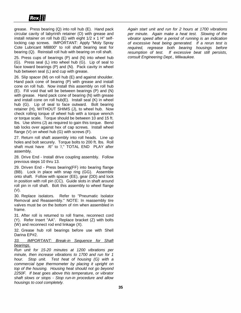
grease. Press bearing (Q) into roll hub (E). Hand packcircular cavity of labyrinth retainer (O) with grease andinstall retainer on roll hub (E) with eight 1/2 x 1 H" self-locking cap screws. IMPORTANT: Apply "Moly SprayCote Lubricant M8800" to roll shaft bearing seat forbearing (Q). Reinstall roll hub with bearing on roll shaft.25. Press cups of bearings (P) and (N) into wheel hub(G). Press seal (L) into wheel hub (G). Lip of seal toface toward bearings (P) and (N). Pack cavity in wheelhub between seal (L) and cup with grease.26. Slip spacer (M) on roll hub (E) and against shoulder.Hand pack cone of bearing (P) with grease and installcone on roll hub. Now install this assembly on roll hub(E). Fill void that will be between bearings (P) and (N)with grease. Hand pack cone of bearing (N) with greaseand install cone on roll hub(E). Install seal (K) in wheelhub (G). Lip of seal to face outward. Bolt bearingretainer (H), WITHOUT SHIMS (J), to wheel hub. Nowcheck rolling torque of wheel hub with a torque wrenchor torque scale. Torque should be between 10 and 15 ft.lbs. Use shims (J) as required to gain this torque. Bendtab locks over against hex of cap screws. Install wheelflange (V) on wheel hub (G) with screws (F).27. Return roll shaft assembly into roll heads. Line upholes and bolt securely. Torque bolts to 200 ft. lbs. Rollshaft must have /6" to '/," TOTAL END PLAY afterassembly.28. Drive End - Install drive coupling assembly. Followprevious steps 10 thru 13.29. Driven End - Press bearing(FF) into bearing flange(BB). Lock in place with snap ring (GG). Assembleonto shaft. Follow with spacer (EE), gear (DD) and lockin position with roll pin (CC). Guide slots in shaft aroundroll pin in roll shaft. Bolt this assembly to wheel flange(V).30. Replace isolators. Refer to "Pneumatic IsolatorRemoval and Reassembly." NOTE: In reassembly tirevalves must be on the bottom of rim when assembled inframe.31. After roll is returned to roll frame, reconnect cord(Y). Refer Insert "AA". Replace bracket (Z) with bolts(W) and reconnect rod end linkage (X).32. Grease hub roll bearings before use with ShellDarina EP#2.33. IMPORTANT: Break-in Sequence for Shaftbearings.Run unit for 15-20 minutes at 1200 vibrations perminute, then increase vibrations to 1700 and run for 1hour. Stop unit. Test heat of housing (G) with acommercial type thermometer by placing it upright ontop of the housing. Housing heat should not go beyond2250F. If beat goes above this temperature, or vibratorshaft slows or stops - Stop run-in procedure and allowhousings to cool completely.
Again start unit and run for 2 hours at 1700 vibrationsper minute. Again make a heat test. Slowing of thevibrator speed after a period of running is an indicationof excessive heat being generated. If a rerun test isrequired, regrease both bearing housings beforeresumption of test. If excessive beat still persists,consult Engineering Dept., Milwaukee.
35

VIBRATION METER - TROUBLE SHOOTING
NOTE: Make all checks using ohmmeter and with ignition key in "off" position, except as noted.
PROBLEM POSSIBLE CAUSE SOLUTIONMeter reads very low. Core stack gap may be too wide. Shim to adjust gap to .010".
Primary ground connection may bebad.
Inspect and repair if connection is notgood.
Meter does not operate. Power supply may not be intact. Check in control box for 12V DCacross terminals H1 and H2. (Key"on" for this check.)
Actuating arm or link may bedamaged.
Inspect (at right end of roll) - repair orreplace damaged parts.
Wire cord may have internal break. Check for continuity - replace entirecord assembly if continuity does notexist.
Coil may be burned out. (At actuatingarm)
Check primary winding (H1-H2) shouldread approximately 26 ohms. Checksecondary winding (X1-X2) - shouldread approximately 1400 ohms. Ifeither reading has very highresistance, coil is burned out andshould be replaced.
Rectifier may be burned out. (Incontrol box)
Disconnect either terminal #7 or #8.Check resistance across 7 and 8.Then interchange probes and againcheck resistance. If both resistancesare fairly close in value, rectifier needsreplacing.
Choke may be burned out. Check across leads. If resistance ishigh, choke needs replacing. (Normalresistance is approximately 1 ohm.)
Meter proper may be burned out. Do not check with ohmmeter. Ifeverything else checks out and meterneedle does not deflect when turned"on", meter needs replacing.
36

FREQUENCY METER - TROUBLE SHOOTING
NOTE: Make all checks using ohmmeter. Engine should be "off" and ignition key should be "off", except as noted.
PROBLEM POSSIBLE CAUSE SOLUTIONMeter registers exceptionally low. Line fuse may be blown. Replace fuse in line under instrument
panel (1 amp).
Power wires may be disconnected. Check and correct. (Key "on" for thischeck.)
Meter assembly may not be workingproperly.
Replace meter assembly - not fieldrepairable.
Meter does not register. Line fuse may be blown. Replace fuse - see above.Power wires may be disconnected. Check and correct. Be sure red wire is
properly grounded. (Key "on" for thischeck.)
Coupling for magnetic pickup gearmay be damaged.
Remove cover by prying. Try to rotategear by hand. If gear rotates, couplingis damaged. Replace roll pin.
Gap between magnetic pickup andgear may not be correct.
Adjust gap. Proper gap is .030".Tighten jam nut. Also clean anyresidue from around gear.
Electric continuity between magneticpickup and meter may be broken.
Under instrument panel, check acrossblack and white wires from magneticpickup, with ohmmeter probes. (Useneedle probes or pointed objects topenetrate wire installation.)- A reading of approximately 100ohms indicates continuity is good.- A reading of much higher than 100ohms indicates an open circuit.If resistance reading indicates an opencircuit, remove connector frommagnetic pickup and shunt the twocontacts in the connector with a shortpiece of wire. Again read theresistance across the black and whitewires.- A reading of approximately 0 ohmsindicates wire assembly is good, butmagnetic pickup needs replacing.Replace pickup.- A reading of very high resistanceindicates wire assembly has a break.Replace connector and cordassembly.
Meter assembly may be damaged. If system has checked out good to thispoint, problem is probably in the meterassembly. Install new meterassembly, as this is not fieldrepairable.
37

38

39

HIGH PRESSURE JOINERHOSE ASSEMBLY INSTRUCTIONS
AEROQUIP 2755-16 AND FC 136-16HOSE AND FITTINGS
Below is a sketch of a hose that has been incorrectlyassembled. The inner diameter layer of rubber hasbeen ruptured, and in many cases the rubber is tornloose into shreds. This condition will cause hydraulicline leaking and eventual hydraulic system failure if notdetected and corrected.Inspect inside of hose fitting assembly for distortion ofthe inner diameter. Make sure no foreign material is leftin the hose. Flush with oil and air blow dry before finalline connection.
CLEAN HOSES AND FITTINGS
CAUTION: It is vitally important that no foreign materialbe introduced into the hydraulic system. Do not removeany plugs from lines, fittings or hydraulic pump or motoruntil ready to make connections. The following steps "a"and "b" must be complied with before makingconnections. Also, it is recommended that when makinghose connections, the male threads be coated with aheavy oil.
a. Fittings - All fittings, regardless if the ends areplugged or not, should be inspected for looseinternal particles, thread burrs, etc. Burrs may bereadily seen or felt and removed, however, dust anddirt may be present inside the fittings. Slush thefittings back and forth in a deep container ofhydraulic oil. Blow dry with clean air.
b. Hoses - Check hoses and hose end fittings for burrsand dirt within the hose. Insert a wire of suitablelength thru hose. Attach a piece of lint-free cloth ofsuitable thickness to the wire. Dip cloth in hydraulicoil and draw cloth thru the hose. Fill hose about 2/3full of clean hydraulic fluid. Rock hose back andforth several times, empty fluid and blow dry withclean air.
CABLE CLIPS (Figure 25)Cable clips are installed on the vibrator control cableand throttle control cable. The purpose of the clips is toprovide a drag on the cables to hold the settingsrequired.The clips are tightened against the cable to a minimumamount to hold their stroke.When a cable replacement is made and/or anadjustment becomes necessary, do not tighten clip downexcessively. Use two clips if necessary.
FIGURE 25
40

SUNDSTRAND (VARIABLE DISPLACEMENT HYDROSTATIC PUMP) AND (FIXED DISPLACEMENTHYDROSTATIC MOTOR), PAGES 49 THRU 61.
HYDRAULIC CIRCUITS
GENERALThe hydrostatic transmission offers an infinite control ofspeed and direction. The operator has complete controlof the system with one lever for speed and direction.
Control of the variable displacement, axial piston pumpis the key to controlling the roller. Engine horsepower istransmitted to the pump. When the operator moves thecontrol lever, the swashplate in the pump is tilted fromneutral.
When the variable pump swashplate is tilted, a positivestroke to the pistons is created. This, in turn, at anygiven input speed, produces a certain flow of oil fromthe pump. This flow is transferred through high pressurelines to the motor. The ratio of the volume of flow from
the pump to the displacement of the motor willdetermine the speed of the motor output shaft. Movingthe control lever to the opposite side of neutral, the flowfrom the pump is reversed and the motor output shaftturns in the opposite direction. Speed of the outputshaft is controlled by adjusting the displacement (flow)of the pump.
The pump and motor are contained in separatehousings. All valves required for a closed loop circuitare included in either the pump or motor assemblies. Areservoir, filter, cooler and lines complete the circuit.
Figure 1 illustrates the internal components of a typicalSundstrand heavy duty hydrostatic transmission.Figure 2 illustrates the general appearance of thecomponents of a heavy duty transmission.
FIGURE 1

VARIABLE DISPLACEMENT PUMPFIGURE 2
CHARGE PUMP CIRCUITFluid flows from the reservoir through a filter to the inletof the charge pump mounted on the main pump whichis driven at pump shaft speed. The purpose of thecharge pump is to provide a flow of fluid through thetransmission for cooling purposes, to supply fluid underpressure to maintain a positive pressure on the lowpressure side of the main pump/motor circuit, to providesufficient fluid under pressure for control purposes, andfor internal leakage makeup.MAIN PUMP AND MOTOR CIRCUITFluid from the charge pump is directed to the lowpressure side of the main circuit by means of one of twocheck valves. The second check valve is held closedby the fluid under high pressure on the other side of themain circuit.Fluid flows in the main circuit in a continuous closedloop. The quantity of fluid flow is determined by pumpspeed and displacement while direction of flow isdetermined by the swashplate angle from neutral.A manifold valve assembly, connected across the maincircuit, includes elements essential to provide the properoperation of the transmission. The manifold valvecontains two pilot operated high pressure relief valveswhich serve to prevent sustained abnormal pressuresurges in either of the two main hydraulic lines bydumping fluid from the high pressure line to the lowpressure line during rapid acceleration, abrupt brakingand sudden application of load.Also provided in the manifold valve assembly is ashuttle valve and a charge pressure relief valve. Theshuttle valve functions to establish a circuit between themain line that is at low pressure, and the chargepressure relief valve to provide a method of controllingthe charge pressure level and also a means of removing
the excess cooling fluid added to the circuit by thecharge pump. The shuttle valve is spring centered to aclosed position so that during the transition of thereversing of pressures in the main lines, none of thehigh pressure fluid is lost from the circuit.COOLING CIRCUITExcess cooling fluid from the manifold charge pressurerelief valve enters the motor case, then flows throughcase drain lines to the pump case, through the pumpcase and heat exchanger to the reservoir. The heatexchanger by-pass valve is used to prevent high backpressure at the heat exchanger due to cold fluid or arestricted heat exchanger.During periods of operation when the main pump is inneutral, the shuttle valve will be centered and theexcess flow from the charge pump is directed to thecooling circuit by the neutral charge relief valve in thecharge pump. When operating at this condition, coolingflow is not admitted to the motor case, but through thepump case and heat exchanger to the reservoir.DISPLACEMENT CONTROL OPERATIONThe Sundstrand Heavy Duty Variable Pumpsincorporate a powered servo system to control theswashplate position with a correspondingly low operatoreffort.The valve assembly is a closed center four-way valvewith the servo pressure ports exhausted at the centerposition. The valve is operated through internal linkageconnections with both the swashplate and the externalcontrol handle. Refer to figure 3, page 51.
Cont'd. on page 51
42

To put the pump in stroke, the control handle (A) movesthe displacement control spool (B) through a spring (C).The spool ports oil under charge pressure (D) to a servocylinder (E). The piston moves the swashplate (F)against the opposite servo spring (G). Both servosprings are constrained so that they can only force theswashplate toward neutral. When the swashplate hasmoved to the angle set by the control handle, the feed-back link (H) returns the displacement control spoolalmost to neutral where it ports just enough oil to theservo cylinder to keep the swashplate at the properangle.
The orifice (K) restricts the incoming charge supply tolimit the maximum servo response rate. Spring (C)allows the operator to rapidly preselect the desiredspeed setting without waiting for the swashplate tofollow-up.When the mixer control handle is moved to neutralposition, the displacement control spool is returned toneutral by a spring (J). This allows oil from both servocylinders to flow into the pump case through the smallunderlaps (I). (Refer to figure 4.) Both servo cylindersare thus exhausted and one of the servo springs (G)mechanically forces the swashplate to neutral.
FIGURE 4
FIGURE 3
43

TROUBLE SHOOTING PROCEDUREBefore Proceeding With Trouble Shooting, Read theFollowing Information!Sundstrand Heavy Duty transmissions must maintainvarious pressures to function properly. Any disturbanceof the proper pressure levels will lead to an inoperabletransmission.
1. CHARGE PRESSURE: The minimum allowablecharge pressure is 130 p.s.i. Normal charge pressure is160 p.s.i. and 190 p.s.i. when pump is in neutral.
2. SYSTEM OR HIGH PRESSURE: The maximumsystem pressure obtainable is controlled by the high
pressure relief valves located in the motor manifold.The relief valves have a two (2) digit number stampedon the exposed end stating valve setting (i.e. “50" =5000 psi). High pressure gauge port (Gauge "B", figure11) monitors far side high pressure' loop' and near siderelief valve.
The necessary gauges and complimentary equipmentrequired are depicted in Figure 10. Their properinstallation in the circuit is depicted in Figure 11.
NOTE: For accurate gauge interpretation, it isrecommended that the pump drive shaft be turning at ornearmaximum RPM.
A. Gauge Connection = 7/16 x 20 SAE "O" Ring -All Series
B. Gauge Connection = 7/16 x 20 SAE "O" Ring -All Series
TROUBLE SHOOTING GAUGESFIGURE 10 TYPICAL GAUGE INSTALLATION (PV-MF)
FIGURE 11
44

SUNDSTRAND HYDROSTATICSERVICE BULLETIN
TROUBLE SHOOTING PROCEDURE
IMPORTANT PUMP AND MOTOR SERVICE NOTE: Always include pump or motor model and serial numbers alongwith the mixer serial number when ordering pumps, motors or service parts. (Do not open any part of the system withoutfirst cleaning the surrounding area.)
I. System* Will Not Operate in Either Direction.* The word system denotes both pump and motor plus all lines, valves, filters, controls, etc., leading to and inbetween them.
Cause RemedyA. System Low on Oil. 1. Check oil level in reservoir and replenish, if necessary.
2. Locate and fix leak or leaks causing the loss of oil.
B. Faulty Control Linkage to Pump. 1. Check the entire linkage to make sure it is connected andfree to operate as it should.
C. Slump and/or Pump Dump Valve Stuck Open. 1. If used, make sure the Slump and/or Pump Dump Valve isclosing properly. Check valve for leakage.
D. Disconnected Coupling. 1. Check to see that the coupling from the prime mover to thepump and the coupling from the motor shaft to the drivenmechanism is not slipping or broken.
E. Low or Zero Charge Pressure (Steady). 1. Install pressure gauge (capable of 600 PSI) in either the 1,N.P.T. in the charge pump or in the side of the main pump.
NOTE: Charge pressure may also be taken by attaching apressure gauge to the port on the rear-of the motor manifold.This port, however, is blocked by the shuttle valve when thehydrostatic system is in neutral; therefore, the system mustbe operating either in the forward or reverse direction toobtain a pressure reading at this port.
2. Set pump speed to at least 500 RPM. Charge pressureshould read at least 120 PSI or more when main pumpcontrol lever is in pumping position and fluid motor isoperating.
3. Low charge pressure may be caused by:a. Charge pressure relief valve in charge pump stuck openor relief valve seat damaged.b. Charge pump drive shaft sheared.c. Suction line or filter blocked or clogged.d. Internal damage to pump or motor.e. "0" ring damaged or missing between displacement
control valve and pump case page66.F. Low and Fluctuating Charge Pressure. 1. Air in system. Air will also cause system to be noisy. Check
all fittings, especially around filter, in the suction line andlocate the point or points where air is being drawn into thesystem. Tighten fittings and joints where air leaks exist.
45

2. Charge pressure relief valve in the motor manifold stuckopen. Pressure will be normal when the pump is in neutralbut low in stroke.
3. Internal damage to pump or motor.
G. Faulty Check Valves. 1. Remove the two ball check valves located in the end cap ofthe pump under the charge pump and check the following:a. Check valve to see if poppet or ball is missing.b. Check to see if the valve seat is eroded.NOTE: If any of the above conditions exist, replace bothcheck valves.
H. Internal Damage to Pump or Motor. Indicated by:1. Low or zero charge pressure (see I-E). Charge pressure may
also fluctuate rapidly.
2. Maximum obtainable operating pressure in both forward andreverse is less than the normal relief valve setting. Chargepressure, which will also be lower than normal, will drop tozero when the maximum pressure is reached.
3. Pieces or flakes of brass in the reservoir and filter.
4. Noisy unit (pump or motor). If either unit is considerablyworn or damaged, the other unit should also be carefullychecked.
I. Plugged Control Orifice 1. Remove displacement control valve from pump and inspectorifice and "0" rings.
II. System Operates in One Direction Only.Cause Remedy
A. Faulty Control Linkage. 1. Check the entire linkage to make sure it is connected andfree to operate as it should.
2. Make sure the control "stop," if used, is not out of adjustment.
B. High Pressure Relief Valve Stuck Open. 1. Switch the two high pressure relief valves. If the systemoperates in the direction in which it would not operate before,one of the high pressure relief valves is stuck open. Bothrelief valves should be examined and the stuck relief valvedisassembled, cleaned, and then reassembled and both reliefvalves should then be reinstalled in the system.
C. One Check Valve Faulty. Follow instructions given in I-G.
D. Faulty Directional Control Valve.(Located on Pump).
NOTE: Do not change the position of any of the hex nuts orthe slotted plug on the end of the control unless it isnecessary to remove the control valve spool.
1. Disconnect control linkage at directional control arm. Movethe control arm back and forth by hand. If it moves freelywith no resistance, even as little as 150, the control valveshould be removed and checked for broken parts or a bentcontrol shaft to which the control arm is attached.
E. Displacement Control Valve"0" Ring Leaking 1. Remove displacement control valve from pump and inspect"0" rings.
46

III. Neutral Difficult or Impossible to Find.
Cause RemedyA. Faulty Linkage. 1. Disconnect control linkage at directional control arm. If
system now returns to neutral, the linkage to the control is outof adjustment or binding in some way.
B. Control Valve Out Of Adjustment.(Displacement control valve will not move out ofadjustment on its own, it has to be done byhuman hands.)
1. See II-D NOTE.
2. If the hex nuts and slotted plug have been moved out ofadjustment, follow steps outlined on page 66.
C. Servo Cylinder Out of Adjustment. 1. Remove the two sleeve retainers.
2. Return the servo cylinders to their original position. Whenthe proper position of the servo cylinders was established atthe factory, both the servo cylinder and the pump housingwere marked with corresponding scribed lines. Matchingthese lines will return the cylinder to its original position andreestablish neutral.
3. Reinstall the two sleeve retainers and restake, if necessary.
NOTE: Servo cylinders do not move out of position on theirown. If they get out of adjustment, it has to be done byhuman hands.
IV. System Operating Hot (TEMPERATURE GAUGE IN RED)
Cause RemedyA. Oil Level Low. 1. Replenish oil supply.
B. Oil Cooler Clogged. 1. Clean cooler air passages.
C. Oil Cooler Being By-Passed. 1. Cooler by-pass valve, if used, stuck open.
D. Internal Leakage. (Usually accompanied by lossof acceleration and power and/or drum stopsturning)
1. One of the high pressure relief valves may be stuck partiallyopen. Install gauges and read the charge pressure andoperating pressure in both directions. If the operatingpressure is 200 PSI or more, lower than normal in onedirection and normal in the other, switch the high pressurerelief valves. If the low pressure also switches to theopposite side of the circuit, disassemble, check and clean thefaulty (low) relief valve. Reinstall and recheck. Chargepressure should be normal at all times.
2. Internal parts of pump or motor (or both) worn. Maximumobtainable operating pressure lower than the normal highpressure relief valve setting in both directions. When thispressure is reached, charge pressure will drop to or very nearto zero. System will also be noisy at this point with the mostnoise issuing from the unit that is most worn. If either unit isconsiderably worn or damaged, the other unit should also becarefully checked. Replace the worn parts in the unitsaffected or replace the complete unit.
47
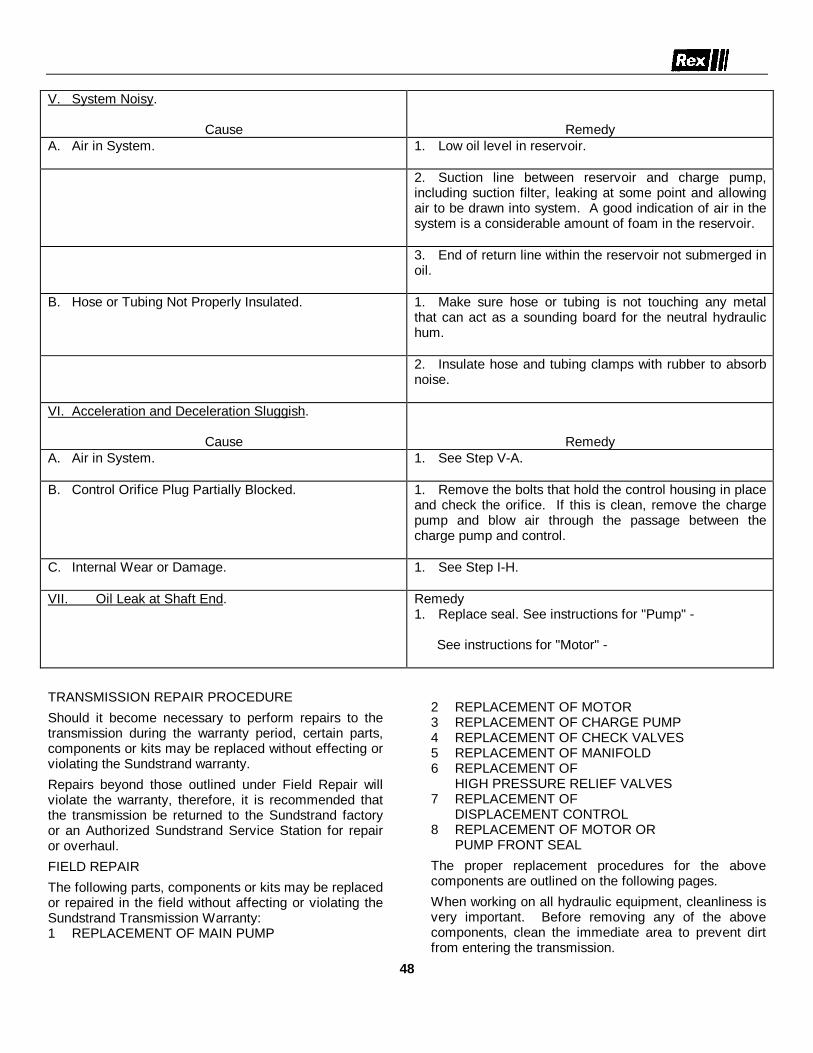
V. System Noisy.
Cause RemedyA. Air in System. 1. Low oil level in reservoir.
2. Suction line between reservoir and charge pump,including suction filter, leaking at some point and allowingair to be drawn into system. A good indication of air in thesystem is a considerable amount of foam in the reservoir.
3. End of return line within the reservoir not submerged inoil.
B. Hose or Tubing Not Properly Insulated. 1. Make sure hose or tubing is not touching any metalthat can act as a sounding board for the neutral hydraulichum.
2. Insulate hose and tubing clamps with rubber to absorbnoise.
VI. Acceleration and Deceleration Sluggish.
Cause RemedyA. Air in System. 1. See Step V-A.
B. Control Orifice Plug Partially Blocked. 1. Remove the bolts that hold the control housing in placeand check the orifice. If this is clean, remove the chargepump and blow air through the passage between thecharge pump and control.
C. Internal Wear or Damage. 1. See Step I-H.
VII. Oil Leak at Shaft End. Remedy1. Replace seal. See instructions for "Pump" -
See instructions for "Motor" -
TRANSMISSION REPAIR PROCEDUREShould it become necessary to perform repairs to thetransmission during the warranty period, certain parts,components or kits may be replaced without effecting orviolating the Sundstrand warranty.Repairs beyond those outlined under Field Repair willviolate the warranty, therefore, it is recommended thatthe transmission be returned to the Sundstrand factoryor an Authorized Sundstrand Service Station for repairor overhaul.FIELD REPAIRThe following parts, components or kits may be replacedor repaired in the field without affecting or violating theSundstrand Transmission Warranty:1 REPLACEMENT OF MAIN PUMP
2 REPLACEMENT OF MOTOR3 REPLACEMENT OF CHARGE PUMP4 REPLACEMENT OF CHECK VALVES5 REPLACEMENT OF MANIFOLD6 REPLACEMENT OF
HIGH PRESSURE RELIEF VALVES7 REPLACEMENT OF
DISPLACEMENT CONTROL8 REPLACEMENT OF MOTOR OR
PUMP FRONT SEALThe proper replacement procedures for the abovecomponents are outlined on the following pages.When working on all hydraulic equipment, cleanliness isvery important. Before removing any of the abovecomponents, clean the immediate area to prevent dirtfrom entering the transmission.
48

Sundstrand Hydro-Transmissiondivision of Sundstrand Corporation
Bulletin 9482Rev. A
world’s most complete familyof hydrostatic transmissions and control systems
September. 1971
CONTENTS
SECTION 1 REPLACEMENT OF MAIN PUMPSECTION 2 REPLACEMENT OF MOTORSECTION 3 REPLACEMENT OF CHARGE PUMPSECTION 4 REPLACEMENT OF CHECK VALVESSECTION 5 REPLACEMENT OF MANIFOLDSECTION 6 REPLACEMENT OF
HIGH PRESSURE RELIEF VALVESSECTION 7 REPLACEMENT OF
DISPLACEMENT CONTROLSECTION 8 REPLACEMENT OF MOTOR OR
PUMP FRONT SEAL
49

FIG. A
FIG. B
50

replacement BULLETIN 9482of main pump SECTION 1
FIG. C
FIG. D
51

replacement BULLETIN 9482of motor SECTION 2
FIG. F
FIG. E
52

replacement BULLETIN 9482of charge pump SECTION 3
FIG. G
FIG. H
FIG. I
53

replacement BULLETIN 9482of charge pump SECTION 3
FIG J
54

replacement BULLETIN 9482of check valves SECTION 4
FIG K FIG L
FIG M
55

replacement BULLETIN 9482of manifold SECTION 5
FIG P
FIG N
56

replacement of high BULLETIN 9482
pressure relief valves SECTION 6
57
FIGURE S
FIGURE T

replacement ofdisplacement BULLETIN 9482
control valves SECTION 7
FIGURE W
58

replacement BULLETIN 9482
of motor or SECTION 8
pump shaft seal
59
FIGURE Y FIGURE Z
FIGURE AA FIGURE CC
FIGURE EE FIGURE DD

replacement BULLETIN 9482
of shaft seal SECTION 8
60
FIGURE FF
FIGURE GG
FIGURE HH

HYDROSTATIC TRANSMISSION START-UPPROCEDURE (Figures 26, 27, 28 and 29)
The hydraulic system has been filled at the factory;however, if for some reason the system has been drained(Refer to Page , Draining and Refilling the HydraulicOil System), the following start-up procedure isrecommended.
NOTE
One common tank supplies oil for the traction drivesystem, vibrator control system and the powersteering system.
The method of filling the hydraulic oil tank is basedon passing the oil thru a #10 micron filter as recom-mended by the "Sundstrand Corp.", manufacturersof the hydrostatic pumps and motors used on theRollers. The filter system (10 micron) is outlinedon pages 71 and 72.
During the start-up procedure, the hydraulic system willbe noisy due to air in the system. As the start-up pro-gresses, the system will be relieved of the air andvoids as oil fills these cavities.
1. Make sure a new and clean oil filter has been in-stalled in the tank and the tank cover replaced tightly.2. Place the "forward-reverse travel lever", item 14,page 9, and the "vibration control lever", item 13,page 9, in neutral (detent position).3. Remove filler cap from the tank and leave the capoff until after the start-up is completed.4. Add a recommended oil to the tank using system asoutlined on page . If a system of this requirement isnot used, the oil must be passed thru a #75 micron filteror a #200 mesh screen.5. Fill tank to sight gauge level. As oil seeps thru theinternal tank filter, into the system, the oil level willdrop. Continue adding oil until the level stabilizes atthe sight gauge level. This may require a period of 20to 30 minutes. CAUTION: At this point the completesystem is not filled.6. Start engine and RUN AT IDLE SPEED (NOFASTER) DO NOT REV. UP ENGINE. Run at idlespeed for a period of 5 minutes. This will purge airfrom the system as oil fills the cavities. Turn steeringwheel during this step from left to right and vise-versa.Steering will be felt in "jerks" as air is purged fromthe steering system. When all air is purged, steeringwill be smooth and decisive. Stop engine. Add oil tosight gauge level.7. Again start engine and run at approximately 1000-1300 RPM for a period of 5 minutes. Check for any oilleaks. Return to idle speed, then stop engine. Add oilto tank if necessary.
8. Up to this point, the hydraulic system has been runwith the pumps and motor in neutral position, and theoil has been going thru a "by-pass" system back tothe tank.
9. If the traction drive pump has been replaced, proceedwith step 9A - "Setting external pump lever arm stops,"figure 27. If the vibration control pump has been re-placed, refer to page 17, "Vibration Frequency Adjust-ment." Then continue with step 10.
A. Set External Pump Control Lever Arm Stops,figures 28 and 29 . Figure 27. Remove the pump con-trol cable from the pump control lever arm. Loosenlock nuts and back off on adjusting screws. Manuallymove the pump control lever arm in one direction toits maximum stroke. This will "bottom" the lever arminternally inside the pump. Now adjust the setscrew
enough so the pump lever arm DOES NOT “BOTTOM”INTERNALLY, BUT “BOTTOMS” AGAINST THESETSCREW. TIGHTEN DOWN LOCK NUT. Repeat theabove in the opposite direction.
61
FIGURE 26
FIGURE 27

62
FIGURE 28
FIGURE 29

FILLING VIBRATORY ROLLER HYDRAULIC OILSYSTEM UTILIZING A PRE-FILTER (10 MICRON)AND AN AIR DRIVEN HYDRAULIC PUMP
1. To recommend a hydraulic oil system filling proce-dure to help in eliminating the following which other-wise could cause almost immediate hydrostatic pumpand/or motor failure.
a. Eliminate the possibility of a "dry startup" bypurging as much air from the system as possibleprior to the initial startup procedure.
b. Eliminate contamination from entering the system.
2. To provide .a list of material to make a pumping andpre-filtering unit as shown in figure 1. It is vitallyimportant that the oil entering the system be filteredthru a #10 micron filter. This is to meet a require-ment of the "Sundstrand" Corp. and also to coincidewith the standard filling and pre-filtering procedureused for initial start-up.
FIGURE 1
63

GENERAL:
The pump (A) shown in figure 1 is a "Lincoln" PowerMaster 2, Model 82734, 4-1 ratio, and must be fittedwith the necessary air control devices.
The filter (B) is a "Bendix" Model #574743 with a #10micron filter element #038082. The filter is a non-bypasstype. Element is of the disposable type.
The system operates on a maximum 35 PSI air pressurewhich the incoming air is controlled by adjusting theAir Regulator (G) to 35 PSI and is read on the airgauge (E).
Adjust the Bleed-Off (safety valve) (F) to bleed orexhaust air pressure in-excess of 40 PSI.
The rupturing pressure of the filter element within thefilter (B) is 150 PSI. CAUTION: Do not exceed themaximum 35 PSI air pressure with the 4-1 ratio oilpump or else the element will be ruptured.
Flush out hose (H) and its fittings before use. Keephose end plastic capped when not in use.
The purpose of the ball type Check Valve (C) is toeliminate a back pressure against the oil pump duringsurges of the pump.IMPORTANT: Oil Filter Element Change - When thefilter element becomes plugged or clogged, oil willnot
penetrate the element. Consequently an air back pres-sure will take place and this will be noticed by thehissing noise of air escaping thru the Bleed-Off Valve(F). Change filter element, 10 micron.
List of Material
A. Power Master 2" Air Motor (4-1 ratio) Lincoln Eng. Co.
B. Filter and Filter Element (10 Micron) Bendix Co.
C. Check Valve, Ball Type, Republic Co.
D. Air Shut-Off Cock, Brass
E. Air Pressure Gauge (0-160 PSI) Marsh Co.
F. Air Bleed-Off Valve, Rockford Co.
G. Air Pressure Regulator (1/4" - 10-125 Pounds)Regulator Co.
H. Hydraulic Hose 3/4" I.D. (Cut Length to Suit.)Plus necessary pipe and fittings to connect and/orassemble the above items.
64
INCOMING AIRQUICK DISCONNECT
SWIVEL TYPEFITTING

65

66

67

68

NoSPIN REMOVAL AND INSPECTION
69

It is important that all parts be thoroughly cleaned for thisvisual inspection.
Check the splines on the side gears and clutchmembers.Remove any burrs or small chipped edges with a stone orelectric burr grinder. If large sections of the spline arebroken away, replace the part. Check the side gear hubsfor fractures.
Cheek the spring heights. They should be within 34'of original height on large models and within %' of originalheight on smaller, L, LS, B, E, J, KS and GS models.
FREE HEIGHT OF NEW SPRINGS
Model Pt. No. Height Model Pt. No. Height
A 62046 3.312 HS-100 63175 2.210B 62122 2.437 J-JS 61028 3.125B-27 62693 1.687 J-100,J5-100 63157 2.120D 61687 2.875 KS 63050 2.375E 61037 2.562 L-LS 61089 1.625E-100 63405 2.310 M-MU 61532 3.000EJ 62213 3.000 N-NS 61293 2.750GS 63673 1.160 R 61875 2.875H 61228 2.750 R-100 63455 3.000H-100 63175 2.210 U 62630 2.780HNS 61933 3.187 Z 62726 4.430
Holdout rings on some Silent and Silent-Overrunningtypes are not slotted and frictional resistance is obtainedby means of a friction spring. Check for fractures orchipping on the holdout ring, also rounded edges on thelugs of the Silent-Overrunning type. A badly worn orchipped holdout ring can cause chipping of clutch teeth.
Friction spring wear should not exceed .003' at points ofcontact. Compare with measurement at unworn portion.Note: Unless extreme care is exercised in removing thispart, it may be damaged during removal. Replace with newpart if, after re-assembly, the frictional resistance is notgreat enough to require a very firm hand pressure to rotate.
The center cam must be free to rotate within the limitsof the keys in the spider. It is not necessary to remove thecenter cam for inspection unless chips are present orreplacement is required.
Check the spring retainer for fractured splines or springseat.
All thrust washers must be omitted unless otherwisespecified. The NoSPIN may lock up solid when the case isbolted together if the thrust washers are not omitted.A failure of the hydrogen copper weld between the cam anddriven clutch will result in erratic operation by alternatelydriving on one side only or driving both wheels with theNoSPIN "locked". If a weld failure has occurred it will bepossible to rotate the cam ring in the driven clutch bylightly tapping the cams.
Inspect the clutch teeth on the spider and driven clutches.Very slight chips can be touched up with a stone. If exces.sively chipped or rounded, these parts must be replaced.Compare the tooth form with those on a new part. If a partis replaced due to chipped teeth, always replace the matingpart as it may have invisible fractures.
Cams on the center cam and driven clutch must not beexcessively chipped. A smooth wear pattern up to 50c%c ofthe face width is acceptable on the clutch cam and centercam.
70
NoSPIN INSPECTION

NoSPIN ASSEMBLY
Check the side gear spline fit on an axle shaft. Be surethe splines do not bind.
Assemble the NoSPIN, being careful to position thespring retainers so that the spring seats inside the cuppedsection.
A bolt and washers can be used to hold the NoSPINassembled, provided the washers are small enough topass through the differential case ends after the casebolts are tightened. If this retainer bolt is not available, itis quite easy to assemble by hand pressure, holding inposition until a case bolt is started.
Before installing NoSPIN and case assembly in thecarrier, again place an axle shaft into each side gear androtate. It should be possible to feel the backlash betweenthe clutch teeth (about 5"). If this backlash cannot be felt,and the side gear is locked solid in the NoSPIN, removethe NoSPIN and check for thrust washers or wrong sidegears.
Assemble the NoSPIN, case and ring gear assemblyinto the carrier and re-assemble the axle in the usualmanner.Lubrication
Lightly lubricate all parts of the NoSPIN as it is beingassembled.
No special lubricant is necessary. The NoSPIN willoperate well in any lubricant as recommended by thevehicle or axle manufacturer.direction on both sides. The rotating wheel should camout easily by hand and a series of uniform clicks will beheard if operating properly. There will be only slight clicksaudible from the Silent-type NoSPIN. If the wheelscannot be rotated freely as described above, remove andinspect the NoSPIN.
If the complaint is jerking, determine if this occurs asthe throttle is advanced at moderate speeds on thehighway or when pulling in low gear under high enginetorques. Unequal tire rolling radii due to wear, unequal airpressures or load on one side can cause jerking at normalhighway speeds with a throttle change. This will alsocause a continuous clicking in the NoSPIN which can beheard in light trucks using the Standard-type NoSPIN.Check the tire pressures. If jerkingor clicking continues, check the rolling radii from theground to the rim or ground to axle shaft flange. Thisdistance must be reasonably equal on each tire.
The rolling diameters of the rear tires can also bechecked by placing chalk marks opposite each other onthe rear tires. Drive the truck a short distance in a straightline. If the rolling diameter is off, the marks will be in adifferent location. Correct be changing air pressure inpresent tires until chalk marks remain in same relativeposition.
If the NoSPIN has worn clutch teeth, they may slip outof engagement under heavy torque loads, resulting in aloud snap and severe jerk of the vehicle. This may occurin low gear
Checking NoSPIN Performance in the VehicleIf the complaint is Locking, Tire scuffing or Tire wear,
drive the vehicle in a tight circle on concrete. The outsidetire should rotate faster than the inside tire due to its greaterare of travel. There should be no evidence of tire slipping orscuffing.NOTE: Extremely short wheelbase vehicles having very
short turning circles may not have enough tractionto drive the vehicle by the inside wheel. It will thenslip and rotate at the same speed as the outsidewheel when driving. This can occur on small forklift trucks, or very short wheelbase trucks.
If a Standard-type NoSPIN is being checked, a uniformclick or indexing sound will be heard. This indexing sound ismore difficult to detect on heavy vehicles and will not beheard at all if a Silent-type NoSPIN is being checked.
Try this while turning both left and right. If there is nodifferential action, tire scuffing will result and the NoSPINmust be removed for inspection.
Another check to determine if the NoSPIN is locked upis to raise both wheels off the floor and rotate one wheelsforward while an assistant holds the opposite wheel firmlyrearward. (Leave truck in gear with engine off). Repeat thistest holding the opposite wheel rearward. Then repeat testin reverse
at near full throttle. Not completely conclusive, but of somevalue, is a test made by spinning the wheels in low gearwhile the truck is in -bumper contact with a solid object.(Another truck can be used with the brakes locked). Agravel surface would be less likely to damage the vehicleduring this test. If a loud snap results or complete loss ofpower to one wheel occurs, the NoSPIN should be removedfor inspection.
A certain amount of backlash exists in the NoSPIN.This space is necessary to. allow the clutch teeth to dis-engage when turning corners. Actually it amounts to aboutA5' but is greater at the propeller shaft because it ismultiplied by the axle ratio.
This backlash can amount to Y/ to 1V turn of thepropellershaft as it includes additional clearances such as splinesand gear tooth clearances. It is not detrimental to NoSPINperformance or vehicle and does not indicate a defectiveNoSPIN.
A throttle change may result in an occasional singlesnap. This is caused by the sudden release of drive fromone clutch to another due to momentary partial engagement.
This occasional snap does not indicate a defective unit.It is a normal characteristic of the NoSPIN, more noticeablein light vehicles.
For complete description of the NoSPIN, see the operation Manual.
71

72

SILENT-TYPE NoSPIN Differential
General Information and Brief Description of Its Construction and Operation
GENERAL INFORMATION
The requirement for a full automatic locking two-way overrunning clutch or differential, for use intransfer and drop cases of multi-axle vehicles as wellas driving axles of all types of commercial vehiclesand passenger cars, has been evident to users ofautomotive vehicles for a great many years.
Detroit Automotive Products' engineers, in con-stant search for a simpler and silent means ofpreventing individual wheel-spin in driving axlesof light weight vehicles and the elimination oftrapped-torques between driving axles, have devel-oped the silent-type NoSPIN Differential, brieflydescribed hereunder.
The principle on which this device operates is
very similar to the regular type NoSPIN Differentialset forth in the forepart of this Manual. The primarydifference in this device is that it may overrun con-tinuously until this movement is completed then itautomatically returns to full locked engagement,whereas with the regular NoSPIN during the over-running cycle the clutch teeth of both the drivingand driven members re-engage after each tooth,causing a slight indexing sound. Positive drive isassured by each type of mechanism when traction islost on either side of the device. Both types thenremain locked and each side must rotate at ringgear speed until normal overrunning is required forturns or the negotiation of uneven terrain.
CONSTRUCTION
The clutch members of the silent-type NoSPINDifferential are held out of engagement while over-running by the automatic positioning of rotatable"hold-out" Cam Ring mounted on each Driven Clutch
Member. See Figures 11, 13 and 15.The exploded view of a typical silent-type NoSPIN
Differential, together with the nomenclature of therespective components, is shown in Figure 11.
A-Spider-Center Cam Ass’y B-Driven Clutch Members and ”Hold-out” Cam Rings C-Spring Retainers D-Springs E-Splined Side Members
FIGURE 11
As may be seen in Figure 12, the Spider and CenterCam Assembly of the silent type differential is quitesimilar to that of the regular NoSPIN except that theCenter Cam has wider cam teeth to carry the twosets of cams on each Driven Clutch Member, one
fixed, the other rotatable. Note the Spider has onelong tooth or key on its inside diameter which engagesa slot, of predetermined width, in the Center Cam.This slot limits the travel of the Center Cam to eitherside of the clutch teeth of the Driven Clutch Member as
73

73

TIRE PRESSURES - Check daily.
23.1 x 26 Diamond Tread - 15 PSI (SP848)
IMPORTANTENGINE COOLING SYSTEM
Several brands of permanent antifreeze are availablewith sealer additives. The specific type of sealers varywith the manufacturer. Antifreeze with sealeradditives is not recommended for use in Detroit Dieselengines due to plugging problems throughout variousareas of the cooling system.
IMPORTANT:
DRAINING AND REFILLING THE HYDRAULIC OILSYSTEM
Before opening any portion of the hydraulic oil system -namely removing the reservoir tank cover, filler cap ordisconnecting any hoses, it is extremely important thatthe opening points and immediate areas around thesepoints be cleaned with a solvent and blown air dry.
Almost immediate component failure will result if for-eign material is allowed to enter the system. Avoidopening the hydraulic system in dust laden areas.
Do not open hydraulic lines or components that areunder pressure. Shut off engine and make sure enginecannot be started.
Do not drain oil or open system if components are hotto touch. Wait until oil cools.
Do not attempt to reclaim drained oil for reuse.
A. Changing Oil
1. Under normal preventative maintenance, the rec-ommended oil change period is every 2000 runninghours.At the time of changing oil under normal preventa-tive maintenance (2000 hours), it is only neces-sary to drain the oil from the reservoir, and thisalso includes installing a new oil filter element(10 micron). When adding clean oil to the reser-voir, pour the oil thru a 75 micron filter or #200mesh screen if a 10 micron system is notavailable.
2. A complete oil system change must be made ifthe following has occurred. This also requires anew oil filter element (10 micron).a. Replacement of the hydraulic pump and/or
motor.b. A blown hydraulic hose.c. The filter (vacuum gauge) indicates in the
"red". This is an indication of a pluggedfilter element.
d. The oil temperature gauge indicates in the"red". Consult Trouble Shooting Chart.Any time a complete oil system change is made,install the new oil filter element first.
75

LUBRICATION CHART SP848
REF. DESCRIPTION LUBRICANT REMARKSA VIBRATOR SHAFT EP #2 (SHELL DAILY - 2 FITTINGS, 1 EA. SIDE. HAND
BEARINGS DARINA ONLY) GUN ONLY. SIX STROKES EA. FITTINGB STEERING CYLINDER *MOBILGREASE 77 WEEKLY - 2 FITTINGS
ENDSC ARTICULATING JOINT *MOBILGREASE 77 WEEKLY - 4 FITTINGS
BEARINGSD UNIVERSAL JOINTS AND *MOBILGREASE 77 WEEKLY - 3 FITTINGS
SLIP JOINTE TWO-SPEED TRANSMISSION *MOBILUBE HD80-90 CHECK LEVEL WEEKLY - DRAIN, FLUSH
AND FILL TO LEVEL PLUG EVERY 500HOURS. CAPACITY: 41/2 QTS.
F AXLE DIFFERENTIAL *MOBILUBE HD80-90 CHECK LEVEL WEEKLY - DRAIN, FLUSHAND FILL TO LEVEL PLUG EVERY 500HOURS. CAPACITY: 4H QTS.
J GEAR COUPLING- *MOBILGREASE 77 REPACK EVERY 6 MONTHS- REMOVE HYD.HYD. MOTOR TO MOTOR AND DEPOSIT 2 OUNCES THRUVIBRATORY SHAFT SPLINES.
K ROLLERS BEARINGS *MOBILGREASE 77 RE-HAND PACK EVERY 2000 HRS.L HYDRAULIC OIL SYSTEM *MOBILFLUID 300** CHECK LEVEL WHEN OIL IS COLD. ADD
(REFER PAGE 84) OIL IF NECESSARY. CHANGE OIL AND OILFILTER, 10 MICRON (IN TANK) EVERY 2000HOURS. WHEN ADDING OR CHANGING OIL,POUR OIL THRU A #75 MICRON FILTER OR#200 MESH SCREEN. CAPACITY: APPROX.34 GALS. MAINTAIN TANK BREATHER CAP CLEAN.
M PNEUMATIC ISOLATORS - CHECK TIRE PRESSURE DAILY. MAINTAINTIRE PRESSURE AT 25 P.S.I.
N TRACTION TIRES - CHECK TIRE PRESSURE DAILY. REFER TOPAGE 84 FOR MACHINE AND TIREPRESSURES.
S ENGINE FUEL TANK DIESEL FUEL OIL #2D FILL AS REQUIRED. CAPACITY: 55 GALS.T ENGINE COOLING SYSTEM WATER - FREE OF CHECK DAILY. FILL AS REQUIRED.
(REFER PAGE 84) MINERALS - ANTI-FREEZE CAPACITY: 21 QTS.WHEN REQUIRED
U ENGINE AIR CLEANER - CLEAN BOWL DAILY. REPLACE FILTER(DRY TYPE) ELEMENT WHEN INDICATOR SHOWS,IN
THE "RED".*USE MOBIL OIL PRODUCT (OR EQUIVALENT).**IF IT IS NECESSARY TO ADD OR CHANGE OIL IN THE FIELD AND THE RECOMMENDED OIL (OR EQUIVALENT)IS NOT AVAILABLE, AUTOMATIC TRANSMISSION FLUID TYPE "A", SUFFIX "A" MAY BE USED.
76

SECTION II
REPAIR PARTS
FOR
SELF-PROPELLED VIBRATORY ROLLERS
REGISTRATION NUMBERS UBOOFL TO UBOOHF
SP 848
NSN 3895-01-075-2823

INSTRUCTIONS FOR ORDERING PARTS
Order repair parts from your Rexnord distributor. Specify quantity, part number and name of part. Do not order byreference number or state quantity wanted in terms of sets or pairs.
Always give serial number of machine. This is very important. The serial number is stamped on manufacturers' platewhich is attached to the frame of machine.
Be particular to give complete shipping address mentioning town, county and state. Also give billing instructions andaddress. Tell whether to ship via parcel post, express, air express or freight.

construction machinery
Index - Bulletin No. 480 (New Oct. 1977)Model SP848 Self Propelled Vibratory Roller
Effective Serial No. 85HX505
Fische & Grid PageDescription Number Number
Control Console 20Frame, Covers & Guards 38Power Unit
Air Cleaner 1Battery 1Controls 1Engine & Mount 1Hydraulic Pumps 1Muffler 1Wiring Diagram 7
Roll Over Protection 43
Steering ComponentsArticulating Joint 29Cylinder 23Hydraulic Pump 1, 28
Traction Drive ComponentsAxle, Brake & Mounting 12Differential 19Hydraulic System Schematic 11Hydrostatic Motor 15Hydrostatic Pump 1, 6Rear Wheels & Scrapers 40Two Speed Transmission 16
Vibration Drive & ControlsHydraulic Motor 35Hydraulic Pump 1, 36Hydraulic Schematic 32Transducer Assembly 37Vibratory Roll 30Wiring Diagram 9
Always Give Serial Number of Machine

Rexnord Inc.480-1 Milwaukee, WI 53201
(New 10/77) Always Give Serial Number of Machine
Specify Quantity, Part Number and Description When Ordering

-Rexnord Inc.
Always Give Serial Number of Machinefl/\i\11ll Milwaukee, WI 53201 480-2
(New 1 O/77)
r. AIR CP O W E R U :ENGINE MOUNTIJVIBRATION HYDI
STEERING PUMP AhMODEL SP848 DI
NilVGR O
L E01
ANER MUFFLER -CABLES, TRACTION AND
MPS AND DRIVES, POWER;, BATTERY AND MOUNTINGING VIBRATORY ROLLER
IDR T
, coir
S T A TM O U
C O NIVE IUO
cq’d
ij .
Id’
- 42 Amp. iStarting Motor, 12 Volt Sprag Oil Pan,
Shallow, for 10 Degree OperationOil Pan Dipstick. for IO Degree
Oil Pan
1
--
-
--
-
-
-
-
-
----
ITR‘_ PU
L NO.ItemN o .
1!Cont:d.
2
39
10
85
1
)
I
r
EFFE
Desc r ip t ion
iHXSO5Part
Number.........
......
102-9096-I298-5515-68
502-4755-80398-2002-33398-2002-42X203740X 2 0 3 7 4 1398-20000-27398-2002-57
‘298-4! -933 9 8 - 2 0 0 0 0 - 3 7102-9393-IX8005398-2CtOO@64398-l 1000-18JO2-9450- 1
39%2002- I8398-20000-2:‘398-20000-35‘502-63 16-80298-5 149-92
298-205-47
502-S 114-80102-6518-I
298-5 177-92
I temN o .
NO.ieq’d.--
I
i)
c
P -
, ,
---
12.
4
:2
1
f
4
44
:
d
1
141
1
11I
P;trtNumber Descrtption
Adapter, 1 to .500 RatioAir Inlet Housing Gasket 5124405Emergency Shutdown 5186687
(Plate)Pull to Stop Name Plate 5 18425.5Start Name Plate I567238Gasket-Air Inlet Housing
(General Motors Part No. 512440:Spacer - Engine Front SupportRubber Engine Mount Center Bonded- for !4” Mounting Bolt 2” O.D.x 1% ” Assembled Thickness, 1% ”Dia. Mounting Hole (Lord#J-6256-3)
Front Engine SupportCap Screw t/z x 3” U.N.C.Cap Screw 1 % x 5” U.N.C.Flange Yoke - (Spicer 2-2-329)Snap Ring (Spicer 2-7-29)Cut Washer M”Hex Head HC-HT Cap Screw
w x 1% ”Zap Screw 3/s x I ” - SAE Grade 8ock Washer %”
%d Yoke (Dana #2-4-834)“I” RonL -_..
Lock Washer ?:e”Hex Nut T?<e ” U.N.C.Sundstrand Model 22-2052 Hydmstati
Pump (Propulsion) - See SeparateI l l u s t r a t i on
Zap Screw M x 1%” U.N.C.Cut Washer t/z”Lock Washer i/!r flBracket - Propu l s ion PumpExhaust Muffler (Nelson Muffler Carl
#T-14855)Muffler Clamp - 31%” (Maremont
Auto Products No. X 350)Radiator Mounting BracketRadiator & ShroudRadiator Cap - (Included in Item 2(
lO2-9906- 1
. . : . . .
. . . . . .
G.M. Diesel Engine Series 3-53Model 5033.7001 Includmg theFollowing Features (Listed forConvenience Only - (AlwaysRefer to Option Plate on ValveRocker Cover and to Engine PartsBook for Definite Identification)
Flywheel SAE #4 for use withRockford 1 ITT Clutch
Flywhee l Hous ing SAE #4Governor. Variable Speed with Closet
Linkage Set at 2450 RPM No LoacFan - 18” Dia. Suction 5 Blade
(6KI-469)
Air Inlet Housing for Remote MounteDonaldson H.D. Air Cleaner
Lube Oil Filter, F.F. Mounted onOil Cooler
. . Exhaust Manifold - Stde Outlet
II12
13
14
15
16I7
i8
(5146215)Water Connection\ - Less Radiator
ConnectionBattery Charging Alternator 12 Volt
Breather. on Flywheel HousingPlain Rocker Cover with Oil Filler on
S i d e
.
Injectors N50 -Exhaust Outlet Flange - 3” Pipe
Threads -Oil Cooler - Engine Only -C. S. Pullev - 2 Groove - Cone Drive
(5 I26687(6KIA- 153)Tachrometer Drive Mtd. on R.H. I-
Balance Shaft When Viewing Enginefrom Flvwheel End. 90” I-
.........
.........
(C) FISCHE NO. 7 GRID D-2
Specify Quantity, Part Number and Description When Ordering Mel.

4 8 0 - 3(New 10177)
m Rexnord Inc.~\/]\I~~~ Milwaukee, WI 53201
Always Give Serial Number of Machine
Itern P‘KINo. N u m b e r
2 9
3 03 1
3 2
3 3
3 4
:z
3 7
3 8
POWER UNIT. AIR CLEANER MUFFLER - (Continued)ENGINE MOUNTING, CONTROL CABLES, TRACTION ANDVIBRATION HYDROSTATIC PUMPS AND DRIVES, POWER
STEERING PUMP AND MOUNTING, BATTERY AND MOUNTINGMOJE,L SP848 DIRT COMPACTING VIBRATORY .ROLLER
EFFECTIVE SERIAL NO. 85HX505
Descrtptton
502-4765-80 Auxiliary Fan Shroud298-20-98 Drain Cock (Imperial #2OlE)
*502-6328-80 Air Cleaner BracketX203699 Strip - Channel Rubber
$298-5126-92 Mounting Band -Air Cleaner-(Donaldson P4076)
102-9 125-2 Air Cleaner Hose298-9058-86 H o s e C l a m p
i102-9209-1 Air Cleaner - (Donaldson CyclopacFW Series Model FWGlO-003)
102-9209-2 Element for Air Cleaner (Pl I-8159)102-9209-3 Gasket Washer for Air Cleaner -
(Donaldson Pan No. P18462)102-9209-4 Cup Gasket for Air Cleaner -
;502-4850-80(Donaldson Part No. PlO-1401)
Tube - Air Cleaner298-6509-68 Indicator-Air Filter - ‘/a x ‘/s
Connec to r F i t t i ng wi th Bu i l t i n Sa feFilter (Bacharach Code No. 63-003!Model 63-7001)
298-5054-92 Oil Cooler (Yates #RD-L-6556,General Radiator Inc. #@Z-2409,
I
Perfex #A18-953 or Equal)398-17000-70 Square Head Set Screw M” x 1%”398-l 1000-19 Hex Nut M”
b298-6085-17 1 Neutral Stoo Switch (Cole-Herse#9233) ’
102-6973-lX 2 0 2 8 2 1
Nut -Neutral Stop SwitchBall Joint J/q” (Tourek Type SR No.
S R 107G)298 157-47 Bracket - Cable Clamo -
[298-158-47(Morse #A21600) ’
Cab le C lamp t/x” for 43C Ser ies Cable(Morse #A21227)
398-1000@48 Rd. Hd. Mach. Screw 10-24 x %”
1R<
tY9
L
VO.eq’d-_
1
fI
i
8
11
1
:
1
hemN O .
3 9
4 0
1:.4 3
4 4
24 7
4 8
4 9
5 0
5 1
2
j
z2
1
;
1
f5
$’5
_, 5 1
33
.’ 3
1’
Pa r tNumber
98-146-47
98-10000-4698-llOOO-1698-263~47
02-30528-l02-6494-8098-5 154-92
02-8704- 1
02-4786-I02-30614-I02-2 157-8002-4399-8098-2002-502-4257-8 1
02-4257-80
98-2002-2 198-20000-3902-3283-l98-2006-65
02-5 I64 1
Descr ip t ion
Cable Clamp I” Hole Centers2-l 3/64 Dia Holes for 30 SeriesCable (Morse #A3 1804)
Rd. Hd. Mach. Screw #lO-24 x %”Hex Heavy Nut #IO-24Cable End IO - 32 UNF Female -
‘h - 28 Male (Morse A31 126)Bracket - Muffler SupportPipe - Down ExhaustExhaus t Extens ion - ( S t e m c o M f g . C
#27-10257)Vibratory Hydrostatic Pump-
Model 22.203 I -
B r a c k e t - Steer ing PumpSheave - Steer ing PumpL e v e r - StopFront Engine SupportCap Screw !< R x I */4 ” U.N.C.Rear Engine Support (R.H.) -
(Ooposite of Illustration)Left Rear Engine Support -
(As Illustrated)Cap Screw % x 1%” U.N.C.Lock Washer %”AdapterSocket Head Nvlock Cap Screw j/s x
1 l/4 ” (Heat Treated)Drive Plate
(C) FISCHE NO. 7 GRID D-3
I-
F
e
0 .
I
JO.:q’d.
1
1
6?
rnfl/ Specify Quantify, Part Number and Description When Ordering

-Rexnord Inc.j’////j[111 Milwaukee, WI 53201 4 8 0 - 4
Always Give Serial Number of Machine (New 10177)
POWER UNIT, AIR CLEANER MUFFLER -(Continued)ENGINE MOUNTING, CONTROL CABLES, TRACTION ANDVIBRATION HYDROSTATIC PUMPS AND DRIVES, POWER
STEERING PUMP AND MOUNTING, BATTERY AND MOUNTINGMODEL SP848 DIRT COMPACTING VIBRATORY ROLLER
EFFECTIVE SERIAL NO. 85HX505Item
IPart
N o . Number
5 5 tO2-7360- I
5 6
57 j 102-7949-l
Desc r ip t i on
HubDrilled Cap Screw s:e x %” - HCLock Washer ‘::.”Joint -Center Bonded -
(Lord #JA-6250-I)‘Drilled Cap Screw - sAs x 1%
HT-HCAdanter Plate- Hydraulic PumaH.T. Can Screw r/z x I W” U.N.C.Cut Washer r/z” S.A.E.Can Screw % x 1”’ U.N.C.Cao Screw W x 2%” U.N.CCao Screw 95 x 1%” U.N.C:Cut Washer *h”Self Locking Nut W : 13 U.N.C.
(McLean - Fogg - Uni - Torque)Hydraulic Pump-Steering-
Constant Disnlacement - Vane
I 1-Ill- 6
6
12
12
:47
:3
3
6 5
f !:
:f7071
502- 134 I-90 Fuel Line (Suction) 6 ft. lg.398-t4000-13 Outside Hex Mall -Pine Bushine
7 4 502-2786-807 5 398-14000-57 6 298-276-Z
]502-4625-80
502-2980-80298-6543-17
502-8 113-80291251-48102-10186-l298-207 l-62
Desc r ip t i on
Bracket-Throttle and GovernorPull to Stop Cables
Control Arm -Governor ThrottleSolenoid Switch I2 Volt - Grounded
(CoIe - Hersee #24037) IgnitionLever - Pump Control“u” JointAir Intake TubeAdapter-Union % c Male NPT x
% c Female - 90’ (Anchor#4MA-4UFS)
% x .ys ”Hose Asremblv - Return Fuel LineOutside Hex Bushing % x */4 ”Rod End - Female - y4” Bore -
*/4 - 28 NF Thread
NoRea’d .
58
--Type - 7.5 GPM - -i 500 PSIRelief - Manifold Type - R.H.Rotation IVirkers %V'TM
1 i / lpO2-8672-6 i CO~fi~mr~~&Vifi~I~t~ 1 *
4 2Separate Illustration 7 7
Flange - Yoke AdapteSocket Head Nylok Can
m I- IkO2 8128-80(Secure with-“Lo&e
Air Intake Adanter Tut
Type - 7.5 GPM - 1500 l%iRelief - Manifold Type - R.H.Rotation (Vickers #VTM42-60-75-15-MD-RI-14) SeeSeparate Illustration 1
58 Flange - Yoke98-2006-23
Adapter 1Socket Head Nylok Cap Screw ${e x 1”
45 9 502-8128-80
(Secure with “Loctite Nut Lock”)
398-2001-58Air Intake Adapter Tube 1
16 0 102-9120-l
Hex Hd. Cap Screw J:ti x %”1
61 298-5701-68Radiator Hose - Upper 1% ” I.D.Radiator Hose - 2” I.D. -Flex ib le
6 2 13” Overall (General #2 18 or 1298-9027-86 Equal)Hose Clamp II%:, to 2%” (Breeze
#OS100 M36 orEither CUD Equal) -
463 298-92-47 (63/64 CUD Dia.. I/s 27
I 1Control Cable - Vibration Pump
(Morse 43BCl14) 114” lg.- !Model 848 only (as illustrated) 1
7 8 I 102-8672-6
102-7554-51
7 9 1 102.864211
8 0 IO2-7957- I
Control Cable-Direction(Morse Part No. 43B168) 1
Throttle Control Cable - 30M SeriesVernier Control (18 Turns) BlackKnobs Control and Brake, Part No.D44194, Clamp Type-ThreadedEnd IO-32NF-3 with Boot #A45477 1
“ P u l l t o S t o p ” C a b l e ( M o r s e B 4 8 7 0 1Cable with B42978-IA Red “T”Handle)
:1
1
WT. li$, Overall ‘Heighi, SpringLoaded Cover (Gits #1003-S28) 1
‘I 81 102-8022- 1 Cable Mount (Emergency Stop) f
(C) FISCHE NO. 7 GRID D-4
Specify Quantity, Part Number and Description When Ordering

480-5(New 10177)
w Rexnord Inc.fl/\jj11ll Milwaukee, WI 53201
Always Give Serial Number of Machine
POWER UNIT, AIR CLEANER MUFFLER -(Continued)ENGINE MOUNTING. CONTROL CABLES, TRACTION ANDVIBRATION HYDROSTATIC PUMPS AND DRIVES, POWER
STEERING PUMP AND MOUNTING. BATTERY AND MOUNTINGMODEL SP848 DIRT COMPACTING VIBRATORY ROLLER
EFFECTIVE SERIAL NO. 85HX505
ItemN o .
i:8 4
8 5
I PartNumber
502-2693-80102-7766-l398-20000-372 9 8 - 2 0 1 2 - 7 1298-703691
j298-5OQ2-92
, ’
Clamp - Cab leCable Brake (Morse A44386, Series 60) :Battery Cable 73” LongBattery Cable - 30” Long :Battery-Diesel Starting - 12 Volt
AABM Group Size 4D - Delco#759 or Exide D-4D-4939 or Equal) 1
Clamp - Battery
I
IBolt-Battery Hold DownLock Washer 3/g” :Nut W” 2
-1
Air Cleaner Elbow (Rubber - 90“) 1
(Cl FIXHE NO. 7 GRID D-5
Em/l Specify Quantity, Part Number and Description When Ordering

~Rexnord Inc.fl/i1\[11# Milwaukee, WI 53201 4 8 0 - 6
Always Give Serial Number of Machine (New 1 O/77)
ItemN o .- -
I
:
467
;IO
I131 4IS1 617
1;
HYDROSTATIC PUMP-TRACTION DRIVESUNDSTRAND MODEL NO. 22-2124
REX PART NlJMBER 102-9450-IMODEL SP848 VIBRATORY ROLLERS
Part Description No.Number Req’d.
102-4365-4 Control Valve I102-4365-6 Gasket -Control Valve I102-4365-7 Charge Pump I102-436S- I I Gasket-Charge Pump I102-4365 I2 Check Valve I102-4365-l Seal Kit (Contains Items 7 thru I I - Not Sold Separately) I
. . . . . . . . . Shaft Seal
. . . . Housing Seal. . . . . .. . . . .
i i)iiij&47102-4365-52102-4365-48
Seal Spring“0” Ring“0” RingRetaining RingCharge Pump Relief Valve PoppetCotter Pin
. . Reference Only - (Pin)IO2-4365-50
i Oi-4jB5.5 I102-4365-46
WasherReference Only - (Orifice)“0” RingControl Shaft Handle
Note - Do not attempt repairs beyond parts listed .,boye -Rebuilt-fully warranted pumps and motors are available frorstock at special exchange prices.
(C) FISCHE N O . 7 G R I D D - 6 -
Specify Quantify, Part Number and Description When Ordering Em/l

480-7 construction machinery(New 10/77)
Always Give Serial Number of Machine

ml/l construction machinery 480-8/New 101771
WIRING DIAGRAM-NEGATIVE GROUND ALTERNATORM O D E L S P 8 4 8 S E L F P R O P E L L E D V I B R A T O R Y R O L L E R S
IfClll
NO.Pnrt
Number D e s c r i p t i o nNo.
Req’d.
: 298-6540-17 102-30507.1 Wire Field Set Switch 1 13 102-9790-I W i r e4 102-9791-I W i r e :5 298-3255-17 Battery - 170 Amp. 16 203027-I W i r e7 203027-2 W i r e E
t102-4375-I Instrument Cluster298-86-17 Connector :
(C) FISCHE NO. 7 GRID D-8
Always Give Serial Number of Machine

480-9 construction machinery(New 10/77)
Always Give Serial Number of Machine

IBa#nndRexnord Inc.fl/jll1111 Milwaukee, WI 53201 480-10
Always Give Serial Number of Machine (New 10/77)
WIRING DIAGRAMMODEL SP848 VIBRATORY ROLLERS
lrcm PartNO. Number Desc r ip t i on
1 1 1 0 2 - 4 3 7 5 - l 1 I n s t r u m e n t C l u s t e r
f298-6176-17 Key Switch298-5004-17 2 Amp Circuit Breaker
4 2 9 8 - 5 0 0 5 - 1 7 20 Amp Circuit Breaker5 1 1 0 2 - 9 8 9 3 - I /Speedometer
8 I 298-6067-17 1 Stdri Bution
1;::13141.516171819
E2 2
2 9 8 - 6 1 2 3 - 1 7 Toggle Switch298-15018-17 Horn Relay298-26085-17 Bullet Terminal
Vibration TransducerWire Terminal -For +‘a Bolt.Battery (Standard)
/ 298-26026-17 Wire Terminal For #lO Stud
1 %%~!: ~~e$&~~ Pick-w
2 5
2 9 8 - 6 0 8 5 - 1 7 Neuiral ftart Swiich298-12015-17 Flood Lamps298-6543-l 7 Solenoid Switch IICiN)1 0 2 - 9 1 4 8 - I Horn Button Kit298-26087-17 Connector - 3 Wire Bullet2 9 8 - 4 6 - 9 8 Solenoid Switch (o/c Wet)298-6524-17 Limit Switch102-6440- 1 Pump (See Separate Iliustration)
P.lrtNumber
31
3’53 43 53 63 73 83 940
t:4 344454 6
4 7
4 84 9
2:
:i:
:z5 65 758
298-86- I7102-9 149-3102-9 149-41 0 2 - 3 0 5 2 3 - I298-260341 i1 0 2 - 9 7 9 0 - I1 0 2 - 9 7 9 1 - I203027-I1 0 2 - 3 0 5 2 7 - l1 0 2 - 3 0 5 0 3 - l1 0 2 - 3 0 5 0 7 - l
102-8523- 1
IO2-8523- I102-8523-2
29X-26040- 171 0 2 - 3 0 5 2 4 - 21 0 2 - 3 0 5 2 5 - 21 0 2 - 3 0 5 2 6 - I102-30526-3102-929 I-21 0 2 - 9 8 5 9 - I298-52. I75 0 2 - 2 X 2 9 - 8 01 0 2 - 3 0 6 7 3 - I1 0 2 - 3 0 5 2 5 - I
Desc r ip t i on
HornDial LightLight Kit (Instrument Cluster)Connector - SolderlessNut - BracketBracket - HornWire SetWire Terminal For l/4 StudWire I ft. 0” lg.Wire I ft. 3” lg.WireWire I ft. 0” lgWire SetWire SetNot Used
I NO.Rcq’d.
1Battery Cable 6 ft. 1 in.
tSP848 only)long
IBattery Cable 6 ft. 1” lg. (SP900 only)Battery Cable 2 ft. 6” lg. fSP848 only) )Batterv Cable I ft. 7” lg.Wire 3 ft. 1” lg. 1’Wire 3 ft. 6” lg. 2Wire I ft. 0” lg. SWire 3 in. lg.Wire (SO # 14-4) 1 SO” lg.Wire Set I ft. 6” lg.Seal for Toggle SwitchWire 1 ft. 8” le.Wwe - I4 Ga. 2 ft. 6” lg.
I
IWire - 14 Ga. I ft. 3” lg. 1
I .--..-... L . ---- --.-...--.- I
(C) FISCHE NO. 7 GRID D-10
Specify Quantity, Part Number and Description When Ordering Elm/l

HYDRAULIC SYSTEM - TRACTION DRIVE480-I 1
(New 1 O/77)
Id To Vibra.tor Pump
em Part0 . N u m b e r
1 102-03691-032 102-03688-02
3 502-02783-814 502-08005-80
5 298-08118-866 298-08078-867 102-9450-l8 102-03849-039 102-01594-04
1 0 298-0803%8fZ1 1 398-02005-56
602-10051-01102-08418-01
12 102-07864-01
I
398-14000-91398-14000-8s398-14006-15
1 3 102-08510-011 4 2980013>5315 502-02733-m16 102-07320-0117 298-800 I-89
-.---- - - -
Description I N o .Rep’d.
Hose Assembly, 1” SAE x 42%” Lg.Hose Assembly, ‘/,” NPT to 1’4,” JIC x82” Lg.Hose Assembly, ‘/I” JIC x 42,’ Lg.Hose Assembly, l/1” NPT to ‘4” JIC x20” Lg.Elbow ‘/,” x 45”Straight Adapter, $” NPT to l’&*, JIG
a ‘ )Hydraulic Pump, Traction (See ContentHose Assembly, I/” NPT x 30” Lg.“0” Ring, l’/;,,, I.D. x l%,‘, O.D.Split Flange Clamp 1”Cap Screw Y,” x 1%”Hydraulic Tank, in&. the following:Plate, CoverGasket, CoverPipe Cap, 1”Pipe Cap, Y,”Pipe Cap, l/1”Tube, ffydraulic TankElement, FilterCover, Hydraulic TankCap, FillerBreather
1148
1 611111212111
J&e ‘73I
2
(C) FISCHE NO. 7 GRID D-11
Always Give Serial Number of Machine Em

Rexnord Inc.480-12 Milwaukee, WI 53201
(New 10/77) Always Give Serial Number of Machine
Specify Quantity, Part Number and Description When Ordering

~Rexnord Inc.
Always Give Serial Number of Machinefl/\j\Ilmfi Milwaukee, WI 53201 480-13
(New 10/77)
c- --TRACTION DRIVE TRAIN AND AXLE MOUNTING
MODEL SP848 VIBRATORY ROLLERS
i 398-2002-28 398-20000-354 298-3 I 15-68
:, 58183-20 502-6457-807 398-200.5-378 2 9 8 - 3 6 - 9 79 398-2002-89
IO 402-4803-l1 1 298-349-212 298-350-213
14
1:‘ 1 0 2 - 3 0 4 7 9 - l398-2002-25
Li502-8343-80398-14005-7t
19 IO2-9798- 1i’: 2 9 8 - 3 5 2 9 8 - 3 5 2 - 2 1 - 2
;:1 0 2 - 4 7 8 0 - l402-2639-2IO2-980% I102-30455-I
ST 298-31 58486-20 14-68it 402-I 398-6001-87 768-2
z:102-9802-t398-11001-89
3 2b298-4006-475 8 4 8 6 - 5
33 5 8 4 8 6 - 7158486.20
Descrrption
Differential Assembly - ReferenceOnly - See Separate Illustration
H.T Cap Screw % x 2”Lock Washer r/2”Oil Seal (National 410082)Shim (.020” thick)Gear BoxH.T. Cap Screw % x 2”Hardened Washer %”Cap Screw % x 1”Shaft-Pinion GearBearing Cup (timken No. 28622)Bearing Cone (timken No. 28678)Spacer-Shim (.005”) as requiredShim (.007”) as requiredShim (.020”) as requiredCoverH.T. Cap Screw r/z x I % ”Cover with Oil Level HoleSquare Hd. Pioe Plug a/4 ”Spacer -Bearing Cup (timken JM714210)Bearine Cone (timken JM714249)A x l e S h a f tGear - 43 TeethSpacerRetainer - BearineShim (.020”) -Oil Seal (National 415011)Wheel HubStraight Key U, x %I x 2%”WasherLock Nut
l’h” - 1 2 N F - 3Hub CaoShim (.005”) as req’d.Shim (.0075”) as rea’d.Shim (.020”) as req’d.
llcmN o .-. -
3 4
3’:
:53 940
:i
2
PartNumber
102-30459-l398-2001-77398-20000-3’102-98 16- 1502-6459-80502-4986-80398-2002-57398-l 1000-2:398.2OOOf-41398-20000-2;102-9726-i
4 5 102-9726- 10
102-9726-I 1102-9726-12
102-9726- 13
102-9726-20
102-9726-14
102-9726-15
102-9726-16102-9726-17
46
1 0 2 - 9 7 2 6 - 1 8
102-9726-19
102-9726-2 1
Dcwrrption
Cover - Gear BoxH.T. Cap Screw % x 1”Lock Washer %‘ISpacerStrut - Gear Box & Motor MountSumaort - Disc BrakeH.F. Cap Screw sh x 1% cNut H”Lock Washer % *Cut Washer s/R ”Disc Brake Mechanical Caliper
(H. H. Products No. 00-04270)Consistine of items 45-46 & 47
Cam Side SGbassembly (H. H.Products No. 99-04306)Consisting of:
Pix (H. H. Products No. 33-04305)Cam Side Housing (H. H. Prod&
No. 99-02564)Pad Holder (H. H. Products No.
99-06212) includes FrictionMaterial and Pad HolderAssembled
Friction Material (566sintered)(H. H. Products No. 57-00306)
Spring - Pad Retainer (H. H.Products No. 06-03356)
Pin, Push (H. H. Products No.05-05790)
Cam (H. H. Products No. 18-02918)Washer (H. H. Products No.
03-02772)Jam Nut (H. H. Products No
66-04953)Cotter Pin (H. H. Products No.
05-04167)Carrier Side Subassembly (H. H.
Products No. 99-062 14)Consisting of:
(C) FISCHE NO. 7 GRID D-13
NO.Rcq’d.
21 6164
;4
::4
1
:
1
1
1
1
21
1
2
2
1
Specify Quantity, Part Number and Description When Ordering izmll

480-14(New 10/77)
m Rexnord Inc.(6111111111# Milwaukee, WI 53201
Always Give Serial Number of Machine
4 7
48
49505152
53
5 45 556
51
58
5 9
6 0
61
2:
Par tNumber
-__-_1 0 2 - 9 7 2 6 - 2 2102-9726-23
102-9726-13
102-9726-20
102-972614
IO2-9726- 19
102-9726-24
298-90-93298-2059-7 1102-30533-I398-2005-203 9 8 - 1 1 0 0 0 - 2 1398-2OOOCL38298-6075-9 1
102-7322-10
I’ 1
t
1
1
‘
(
1
(1
1
I
I
‘‘1
d
Journal & Bearing Kit -
298-6076-91398.2004-83398-20000-38.398-l 1000-211 OZ-8506- I
(included in item 52)C o m p a n i o n F l a n g eH T. Cap Screw 7/lri x I %I ”Lock Washer Tts”Hex Nut - ;& I,Hydros ta t i c Moto r - ( S u n d s t r a n d
398-2005-88398-20001-23298-4037-47
Nylok H.T. Cap Screw M x I % ”S .A.E . Cu t Washe r M”Wheel Stud (Motor Wheel Co. No.
298-5-7 1502.9803- 1102-9803-2102-9803-3398-2004-3 1398-2OiMC28
83589) (Electrw Wheel Co. No.FSl5262) (Budd No. 43806)
‘Jut - % -16 NF (Budd No. 37888)shim (22 Gauge) - as required<him (18 Gauge) - as requiredshim (12 Gauge) - as required-J.T. Cap Screw % x Z/4”Tut Washer %”
TRACTION DRIVE TRAIN AND AXLE MOUNTING -(Continued)MODEL SP848 VIBRATORY ROLLERS
Pix (H. H Products No. 33-04307)Carrier Side Housine (H. H.
Products No. 12-02544)Pad Holder (H. I& Products
No. 99-06212) includes FrictionMaterial and Pad HolderAssembled
:riction Material (566 sintered)(H. H. Products No. 57-00306)
Spring-Pad Retainer @I. H.P r o d u c t s N o . 0 6 - 0 3 3 5 6 )
Iotter Pin (H. H. Products No.OS-04 167)
Ferry Hd. Cap Screw s-13 x 3” loq(H. H. Products No. 66-04540)
:ap Screw 5/8 x 5lA” GRD.#~lock Nut %”DISC - Brake, Speedometer-LT. Cap Screw 7;;s x 1%”riut Tic”ack Washer &”‘U” Joint Assembly (Dana
9012-SF)
Model 22-3055)
No.Req’d.
1
1
__-I temN o .
64
2267
1
1 68
1
2 69
70
;:73
3:76
177
78
79808182
1
d83
1
PartNumber
298-2035-7 t102-9804- 1398-20000-42502-6473-80
‘298-6014-68
102-30477- I
298-129-47102-99 I7- 1298- 103- 1 7502-205-80298-2603 t-1 7IO2-30484- 1602-8409- i
w502-4988-80102-7287- I
.398-99012-9(402-649-2502-4972-80298-2035-71
,39X-2004-64X7733398-l 1000-41.398-2OMO-35102-9727-I298-2042-71298-6000-34502-8323-80502-8322-80298-37-97X204135398-2OOOW28502-8455-80
Desc r ip t ion
Lock Nut % ” UNC“U” Bolt % ”Lock Washer % IWheel (Model 850 only)
Optional 18:OO x 26 All WeatherTire (Model 850 Only)
Emergency Parking Brake Cable
Clevis PinBracket -Speedometer Pick-upMagne t i c P ick -up - SpeedometetCord AssemblyZonnectorS u p p o r t - M o t o r A d a p t o rTransmiss ion Assembly - Reference
Only-See Separate IllustrationSupport - TransmissionScrew (Sh i f t Yoke Block)Wire ,045 Dia., SAE 51430Shift BlockLever-Shift BlockNutHC. HT. Hex Head Cap Screw % x :B a l l J o i n tHex Nut ‘h” U N.F.Lock Washer l/2”Shift RodNutRolloin ?<s x 1%”Shift LeverArm - Shif t LeverWasherBa l lCut Washer % ”Bracket for Shift Block
(C) FIXHE ‘.- 7 GRID D-14
- -.No.
:eq’d.
26
42
2
2
2
1
1
t
1
:
t
t1
;1
22
;1
:2
:1
fzml Specify Quantify, Part Number and Description When Ordering

-Rexnord Inc.
Always Give Serial Number of Machinej’j//il111# Milwaukee, WI 53201
-- - --.-- -___
FIXED DISPLACEMENT HYDROSTATIC MOTOR SERVICE PARTSREX PART NUMBER 102-8506-I (SUNDSTRAND SERIES 22-3055)REX PART NUMBER ‘102-6123-I (SUNDSTRAND SERIES 23-3008)
MODEL 848 VIBRATORY ROLL TRACTION DRIVE
llcm PartNo. Nun&r Description No.
Req’d.
1i
102-13GS-78 -“ -Mnnlfold Assembly (Series 22 only) 1102-4365-l 4
I
Manifold Assembly (Scr~es 23 only) 12 1021365-l Seal Kit (Series 22 only)
102-4365-2 Seal Kit (Series 23 only) :3 1024365-21 Relief Valve Assembly (Series 23 only) 1
1024365-77 Relief Valve Assembly (Series 22 only) 1
NOTE: Rebuilt - fully warranteed pumps and motors are available fromstock at special exchange price.
(C) FISCHE NO. 7 GRID D-15
480-I 5(New 10177)
Specify Quantify, Part Number and Description When Ordering mill

Rexnord Inc.480-16 Milwaukee, WI 53201
(New 10/77) Always Give Serial Number of Machine
Specify Quantity, Part Number and Description When Ordering

480-I 7(New 10177)
M Rexnord Inc.
MM1111Milwaukee, WI 53201
Always Give Serial Number of Machine
No. PartIlCll~ Number
402-2596-S102-30411-1402-262 1-2398-2002-56398-20000-41398-2002-60
1 Description
Transmission CaseGasketAdapterCap Screw 5/a x 1%” U.N.C.Lock Washer s/”Cap Screw % x 2” -Heat Treated,
U.N .C .102-3368-l402-650-2
Gasket - Countershaft Bearing Cove,
398-2001-77Cover - Countershaft Bearing
398-20000-37Heat Treated Cap Screw % x 1”Lock Washer .%‘I
102-3370-I402-646-2
Gasket - Rear Bearing Cover
102-48i8-1Cover - Rear BearingMain Drive Gear
298-344-2 Bearing Cone (Timken #397) -
298-45-2
298-10032-2298-10030-2298-10031-2298-253-2102-4817-I102-4428-I298-25 1-2298-85 16-34
2 3622” I.D. .8660” WideTapered Roller’Bearing Cup
(Timken #394A)Keyed Washer (Timken #K91512)Lock Washer (Timken #TW112)Lock Nut (Timken #TN12)Ball Bearing (N.D. #1206)Gear - Mainshaft SlidingMainshaftBall Bearing (N.D. #41309)Snar, Ring 1.625 I.D. x 2” 0 D x
.093” Thick (Reliance Divn. ‘ofEaton Mfg. Co. #974)
Spacer - U JointCompanion Flange (Dana Corp.
#3-I-3341)-Circular Type,1.500-10 Spline
102-3359-2298-6076-91
102-7286-I398-3000-18~~8$001-29
298-85 17-34
102-3361-l
TRACTION DRIVE TWO SPEED TRANSMISSIONASSEMBLY PART NO. 602-8409-l
USED ON SP848 VIBRATORY ROLLERS
Nut - Main Shaft (Fuller No. 1846)Cotter Pin ‘/R x 2”
IF
Cut Washer iq<G,” x 2” x 1 l/64”Pipe Plug % ” (Magnetized)Snao Ring - External - I.452
I.D. x 1.764 O.D. x .093 Thick(Reliance Divn. of Eaton Mfg. #916) 1
Soacer I 1
ltcn1
N o .
3 2
PartNumber
x203519
3 33 4
3”:37
102-30598-l102-3379-I102-3360-l1 0 2 - 3 0 5 9 9 - l102-7293-I
38 298-3012-68
:z41424344
tz
ti4950515253
402- 1663-2102-3371-I102-7284-I102-3372-I398-10001-70398-2OooO-64X6326102-7283-l102-7290-l102-3407-l402-647-2102-7287- 1398-990 12-90102-7299- 1298-3520-68
54 402-649-2102-8506-I
55 398-2005-88
56398-20001-13102-1781-l
(Fuller #8337)Oil Seal -Garter Spring Type 2%”
Shaft Dia. 3.355 O.D., ia!$e” Wide,E$ene - Type W4 - #22511)
GasketCover - Hand HoleGasket - Hand HoleRound Head Mach. Screw ?$e x %”Lock Washer :<n”Bearing Ball W ”SpringPlugBar - (Shift Rail)Yoke-ShifterLock ScrewLock Wire (.O45 Dia. SAE 51430)l’himble - Oil Retaining‘0” Ring L/e x % x 1” (National
#6227 15)shifter Blockhydrostatic Motor -
Sundstrand Model 22 - 3055(See Seoarate Illustration)
gylok HC-HT Cap Screw W x 1%(Motor to Case)
7ut Washer %”basket
-Dcscrtption
Bearing - Ball, Maximum CapacityType. Medium Series 40 x 90 x 23M.M. (Fafnir #308WD, MRC#308MF, N.D. #7608, SKF#308AZ)
Low Countershaft GearShaft - (Countershaft)SpacerGear - Countershaft DriveNut - Countershaft Front Bearing
N o .R c q ’ d .
21
:1
1
1
f
f
d
f
f
121
1I
1
441
Parts not included in 602-8409-l two speed transmission assembly.
(C) FISCHE NO. 7 GRID D-17
Specify Quantity, Part Number and Description When Ordering

Rexnord Inc.480-18 Milwaukee, WI 53201
(New 10/77) Always Give Serial Number of Machine
(C) FISCHE NO. 7 GRID D-18
Specify Quantity, Part Number and Description When Ordering

mm construction machinery 480-I 9/New 101771
DIFFERENTIAL ASSEMBLYREX PART NUMBER WITH AXLES AND TUBES 502-6475-80
REX PART NUMBER WITHOUT AXLES AND TUBES 102-9795-IDANA CORP. PART NUMBER WITHOUT AXLES
AND TUBES 27943-28XMODEL 848 SELF PROPELLED VIBRATORY ROLLERS
ItemN o .
1
2
3
4
5
6
7
:101112
1 3I4
15
16
PartNumber
102-9795-10
102-9795-I 1
.
. . . . . .
102-Y7Y5-12
.
IO2-9795- I3IO2-9795- I4102-9795-15102-9795-17
102-9795-22102-9795-16
102-9795-23
102-9795-2 I
Description
Drive Gear and Pmion Assembly KitConsisting of Items 2 thru I3(‘706048-7X)
Kit - Innner Pinion Bearing(*706060X)
Shim - Drive Pinion Adjusting(Reference Only - Sold Only in102-9795-10 Assembly
Baffle - Pimon Bearing(Reference Only - Sold Only inK i t F o r m )
S h i m - P m i o n B e a r i n g A d j u s t i n g(Reference Only - Sold Only inKit Form)
Kit. Outer Pinton Btarmg( ‘706045X)
Slinger - Pimon Bearing Outer(Reference Only - Sold Only inKit Form)
Se.d - Pimon (*35725)Washer - Pimon Nut (*30275)Nut - Pmion (*30271)Gasket- Carrier Cover (*34687)Shml - Dlfferenrial Bearmg
(Reference Only - Sold Only mKit Form)
Bolt - Drwe Gear (‘30266)Companion Flange Assembly
~“1-1-4031)Kit - Diffcrentlal Case Awmbly
Conwtlng of Items I I thru I.7 .mdItems 16 thru 27 (“706050X)
Kit -Differential Bearing(“706047X)
No.R e q ’ d .
1
-
-
-
1
121
N o .
17
I8
19
I7
2 22 3
22 62 7 102-9795-26
2 8 102-9795-24
2 9 102-9795-25
3 0
313 233
PartNumber Description N o .
Req’d
.
. . .
. . . .
. . . .
. .
IO2-9795- I8102-9795-19. . . . . . .
102-4803-I102-9795-20
Flange Half - Differential Case -Not Sold Separately -
~ Cap- Differential Case (Not SoldSeparately)Shaft - Differential
(Not Sold Separately) 1Pinion (Not Sold Separately) 4Gear - Differential
(Not Sold Separately)Ring - (Not Sold Separately)Plate - (Not Sold Separately)Disc - (Not Sold Separately)~lissc- Dished (Not Sold Separately)
- (Not Sold Separately) 1Bolt - Differential Case
(*35104-2) 8Kit - Differential Parts -
Consisting of Item 1 I and 19thru 26 (*706057X)
Kit - Gear Carrier Cover -Consisring of Item I I and Items30 thru 32 (‘706OS9X)
Cover - Carrier(Not Sold Separately)
Plug - Cover (*36472)Bolt - Carrier Cover (‘34822) 10Differential Case (Sold Only as
Complete Assembly Part No.502-6475-80 - See Heading)
Shaft -Pinion Gear :Bolt - Bearing Cap (*500400-20) 4
“Spicer Axle Division. Dana Corporation PartNumbers
(C) FISCHE NO. 7 GRID D-19
Always Give Serial Number of Machine

Rexnord Inc.480-20 Milwaukee, WI 53201
(New 10/77) Always Give Serial Number of Machine
(C) FISCHE NO. 7 GRID D-20
Specify Quantity, Part Number and Description When Ordering

~Rexnord Inc.fl/j~~~~~~ Milwaukee, WI 53201 480-21
Always Give Serial Number of Machine (New 1 O/77)
OPERATORS CONTROLS AT CONSOLESTEERING, FORWARD REVERSE, THROTTLE, BRAKE
MODEL SP848 VIBRATORY ROLLERS
Item PartN o . NUdW Descr ip t ion NO. Item : Par1
Rea’d . No. i Number
1718
19
20
21
E2 4
398-14OCO-52 Coupling rh” N;P.T.298-2172-62 StrSt;dqF 4”a MNPTx % - 16
298-8018-86 Hose Adaptor r/z” MPT102-30292-I Hydrau l i c Cy l inde r - Stee r ing
(Green Mfg. Co. 73-386) SeeSeparate Illustration
102-30437-I H o u s i n g . B a l l S t u d :102-9767-l ‘Ball StGd 2
r102-9768-l Washer (3 Ply. Fabreeka x j/la” thick)I m p a c t
.59077 Spec ia l Washer298-6806-8 Bushing - Radial298-7527-34 Snap Ring - Internal (Truarc
NFOML7Rl1
1398-l 1000-22 Hex Nut ‘h”398-l 1000-87 Castle Nut II/~”398-3000-681 0 2 - 7 0 3 3 - 3
Cotter Pin %a x 2”Hose -?‘a” x 33” long
298-9018-86 Hose Clamp298-2 17 l-62 Elbow - 90° M ” N.P.T.F. x % - 16
422
2
J.I.C. (Anchor 8 Ma - 8 JMS) ’ 1Elbo~--445~ ‘h” NPTFx%,- 16 JIC 1Elbow - 90” %” ‘0” Ring x % - 16
11r I t102-9236-l “ *
ASfeermg Control Valve - (Orbitrol-
Char-Lynn No. YPIZSHF)
298-81 IO-86See Separate Illustration
Adapter - % - I6 Male “0” Ring x
1 0 2 - 3 7 0 1 - 2% - 16 Male JIC (Straight)
102-3701-5Hose 1/2” I.D. x 881/z” lg.
102-3701-IHose Assembly */4 ” I.D. x 136” lg.Hose Assembly *h” I.D. x 75” lg.
29X-45’668 Plastic Tie Clamo
1
4
f1:
2 8 102-8672-6
2 9 298-2762
30 102-7253-I298-6176-17
3 1
‘ 3 2I 298-214-47
298-6067-l 7:: 298-15018-17 502-8 132-80
3 5 298-314-236 298-3 15-2
502-8 107-80502-8249-80
ix502-8 102-80298-5019-8
4 1 102-30130-14 2 298-6004-34
1:502-8 106-80502-8199-80
45 398-17002-1546 102-71901
1;X204135398-2001-92
4 9 298-20 12-7 1
:7398-20000-23102-9089-l
5 2 298-300475 3 298-32-97
(C) FISCHE NO. 7 GRID D-21
Desc r ip t ion
Pla te - S t o p Adjus tmen t 1 1Adjus tment Screw 2Sta in&Stee l Nut 3/S” W i n g 2Vernier Cable Control - Throttle
132” lg. 1Cable ti - 28 NF2 - Exciter.
Control - 3” Travel (Morse43BC90) 1
Rod End - Female */4 rr (Scalmaster -FR-4)
Cable Brake ;Ign i t i on Lock Swi t ch w i th Keys
(Cole Hersee EX-17351) 1Key Only for Ignition LockPush Button -Starter&itch 7Bracket -DetentRe lay - Horn - (DR 111678 1)Bearing - (Fafnir 1103KLLB3)Flancette Bearing Mount (half)
(Fafnir #62 MST)Lever-Direction CableTube -R H. Control - VibratoryTube -L H. Control -VibratoryB u s h i n g (Nylined)Shaft-Dual Coqtrol- (Direction)Roil Pin % x 1% ”Control Lever -VibrationControl Lever - DirectionNylok Socket Hd. Set Screw % x %’Red Knob - Exciter ControlBlack Knob - DirectionCap Screw % x 3”Lock Nut a/R” N.C.Cut Washer %I”Spacer TubeBall Plunger % * Dia. - W-l 1 thd.Thrust Washer
Specify Quantify, Part Number and Description When Ordering ltE!!wl

Rexnord Inc.480-22 Milwaukee, WI 53201
(New 10/77) Always Give Serial Number of Machine
(C) FISCHE NO. 7 GRID D-22
Specify Quantity, Part Number and Description When Ordering

480-23
‘ 6
I t e m P a r tNo. Number
:
:
f769
IO1 112-
102-30292-11‘102-30292-12
102-30292-13102.30292-14102-30292.15
‘102.30292-16‘102-30292.17
102-30292-16102-30292-I 9102-30292-26l 102-30292.21‘102-04714-19
102-30292-22
Dkxription
Steering Cylinder (Green n73.366)Incls. the following Service Parts
Lock NutPolyPacPistonBarrel Assy. .~Rod“0” Ring“0” RingLock WireCapC a p S c r e wDust Seal“0” RingSeal Service Kit Incls. ‘Items 2, 6, 7,
11 8 12
(C) FISCHE NO. 7 GRID D-23
Always Give Serial Number of Machine
IiiIeq’j-
1121111
:2211
1-

480-24 construction machinery(New 10/77)
(C) FISCHE NO. 7 GRID D-24
Always Give Serial Number of Machine

4 8 0 - 2 5[New 10177)
:3458789
IO1 11 21 3141 51 81 718
E2 1
ii2 4
102.09238-01
102-09108-10102991081110289108.12102.09108.13102-08077-21102.08077.22102.08077-23. . . . . . . . . .102.09108-14102-0910&15102.0910618102.09108.17. . . . . . . . . .1 0 2 . 0 9 1 0 8 1 8102-09108-19102.0910820102891082110299238~10102.rJ9238.1110289108.24102-09108.2510289238.121028923813. . . . . . . . .
ORBITROL STEERINQ VALVE - CHAR-LYNN
Description R
Steering Valve (Char-Lynn ‘YPl2-SHR
Terminai & Wlre (21142-l)Insulator Contact (*21138)Spring Contact (‘5029)Washer Contact (‘5028)Ring, Snap (‘14092)Ring, Retainer (*5245)EI$dr~~~~ssy. (‘21148)
Shaft Assy. (‘8783)Ring, Contact (‘21149)Insulator (‘21151)Tube & Flange (‘8785)Cap Screw )L - 18 x % ”Horn Brush Kit (‘8414)Conn=tor (‘21173)Dr ive (*5128)Plate (‘5414)Gear Set (‘5884.8)S p a c e r (*5178)Spline (*5213)Cap, End (‘8481)Cap Screw 12 pt. x 3” (‘538914)Cap Screw ?&“~1&&‘(*210481)Oil, Seal
No.eq’d. No.
-
2 52 82 7
282 93 0
i:3 33 43 5
if383 94 0414 2
PartN u m b e r
1 0 2 . 0 9 1 0 8 2 8. . . . . . . . . .10299108-27
10289108-281 0 2 . 0 9 1 0 8 2 9102-0910530. . ..a . . . . . .102.09108-31. . . . . . . . . ...f . . . . . . .. . . . . . . . . .. . . . . . . . . .102-09108-3210299108331029910834102-0910835102.09108-3810288077-18
‘Char-Lynn Co. pa“Parts Included in
“‘Parts Included inNot Sold Separately.
Description
Plate, Valve Housing (‘843)SealBearing Kit (‘84008) (Incls. 28, 29,
30)Race, Bearing (‘5542)Locator, Bearing (‘5543)Bearing, Thrust Needle (‘5544)“0” RingControl Kit (‘8419) (Incls. 33.41)HousingS l e e v eSpool“0” RingPlug Seal (*21124)Seat, Check (‘859)Ball , Steel (‘18028)Spring, Compression (‘857)Pin, Centering (‘15)Seal Kit (‘5140) (Incls. 24.28, 31. 38)
lumbersal Kit, item 42.mtrol Kit, item 32 -
No.;eq’d.
11
121
:11111111111
(C) FISCHE NO. 7 GRID D-25
Always Give Serial Number of Machine

480-26 construction machinery(New 10/77)
(C) FISCHE NO. 7 GRID E-1
Always Give Serial Number of Machine

~Rexnord Inc.j’/j\jl11li Milwaukee, WI 53201 480-27
Always Give Serial Number of Machine (New I 0177)
PartNumber
X203699102-4375-I
102-4375-I 1
102-4375-12
102-4375-13
102-4375-14102-437S- IS
102-4375-I 61 0 2 - 4 3 7 5 - 1 7298-9032-86298-6176-17
298-6067-17
298-274-47102-9 149-l
OPERATORS CONSOLE & INSTRUMENTS - PANEL SWITCHESEMERGENCY STOP-MODEL 848 VIB. ROLL
Desc r ip t i on
Channel. Rubber 2I n s t r u m e n t C l u s t e r A s s e m b l y
Conststing of: 1Ammeter - (Stewart Warner
#440436) 1Water Temperature Gauge
(Stewart Warner #442784) 1Oil Pressure Gauge (Stewart Warner
#444642)Fuel Gauge (Stewart Warner #441343) :Tachrometer (Stewart Warner
#55 I-LR) 1Glass (Stewart Warner #41 1329) IBezel (Stewart Warner P4 1322)Cable Clamo :Switch -Lock (Cole Hersee
#EX17351) 1Swit;t,SQ,art. Push Button (Cole Hersee
/ 1Key (Cole Hersee #83357) iHorn Package Kit (Includes Item 8
thru 10 Inclusive) 1
ltcln PartN o . Number
89
10111 213
102-9149-2102-9 149-3102-9149-4102-9 149-5
‘298-15018-l298-6123-17102-7957-2
2 3
24
102-8022- 1298- 14,5-47298-30-47502-6433-80298-121-17502-6265-80102-30188-2102-7957-l102-8642-4
102-8743-l602-34-l298-12022-l’102-9892-l
(C) FISCHE NO. 7 GRID E-2
T717
1
Desc r ip t i on-Horn (Delco P90005 13)NutBracketBracketRelay - HornSwitch - LightsCable - Emereencv Stop 48” lg.
(Morse *84X701) ton HydraulicTank)
Mounting Bracket (on Hyd. Tank SheCable Clamp (Morse PA31804)Cable ClamoInstrument PanelP l u g B u t t o n 3 ”Floorboard, ConsoleFlexible Shaft - TachrometerCable-Pull to stoo - 144” lg.Cable-Throttle 132” lg.Frequency MeterFuse and HolderFuse 1 Amo.Vibration Meter (Amplitude)
NO.:eq’d.
1
;
:1
:1
t1
1I
1I
1
t1
Specify Quantity, Part Number and Description When Ordering fzm/l

480-28/New 101771
1
I
-
ternN O
PartNumber
1 102.7949-102 102-7949-113 102-7949-124 102-7949-135 102-7949-146 102.7949- 157 I n2-7949- 16a 102-7949- 179 102-7949-18
1 0 102-7949-19I I 102-7949-2012 102-7949-2 I13 102-7949-2214 102-7949-2315 102-7949-2416 102-7949-2s17 102-7949-2618 102-7949-2719 102-7949-2820 102-7949-2921 102.7949-302 2 102-7949-312 3 102-7949-322 4 102-7949-33- -
HYDRAULIC PUMP - SI‘EERINC;VICKERS PART NUMBER VTM42.60-75.IS-MD-Rl-12
REX PART NUMBER 102-7949-I
Description~-
Mawfold Sub-Assembly (‘281409)Cover Sub-Assembly (‘286613)Control Valve Sub-Assembly (*232797)Ring (*296599)Body Sub-Assembly (*296601)Shaft (*250455)Washer (*2893l)Screw (‘199144)Pin (‘325.59)Screw (*171523)Spring (‘170072)Plug (*175049)Spring (*245507)Pressure Plate (*276396)Pin (‘3.54364)Vane Kit (*922594) (10 pcs.)Rotor (*213859)Cxtridge Kit (‘923092)Bearing (‘222440)Snnp Ring (*I0664 1)BenrIng (1148423)Key (*1606)Snap Ring (*172376)Seal Kit (*922904)-__----- _ _ _ _ _ _
*Vickers Incorporated - P.0. Box 302-Troy, Michigan 48084 part numbers.
(C) FISCHE NO. 7 GRID E-3
Always Give Serial Number of Machine
N o .eq’d
11111113I
411
11
21
11111111
\ 2j6

ARTICULATING CROSS480-29
(New 10177)
Always Give Serial Number Machine ml11111
I t e m Psrt Descripllon No.N o . N u m b e r Iteq’d.
1 402-02616-04 Artuxlating Cross 12 298-10027-02 Inner Bearing Ring 43 298-10028-02 Outer Bearing Ring 4
4 102-08757-03 S h i m (.050”)5 102-08757-02 S h i m (.OlO”) ii
; 1 0 2 - 0 8 7 5 7 - 0 1 1 0 2 - 0 3 9 7 7 - 0 1 Shim Sleeve (.OOS”) - Beating 12 48 102-03978-01 Bearing Retainer 49 398-02002-28 Cap Screw !4 - 13 Y 2” H.C.-H.T. 2 4
1 0 398-08000-07 Lube Fitting, ‘/,I’ NPT ~1610 411 102X18757-04 S h i m (.125”) 21 2 502-04676-80 Bracket -.Bearing Housing 113 502-07107-80 Roll Frame 114 502-7 124.80 Main Frame 11 5 398-02004-80 Cap Screw % x 5 H.C.-H.T. 81 6 298-02035-71 S t o p N u t 3” 8
Mar. ‘73
(C) FISCHE NO. 7 GRID E-4

480-30 construction machinery(New 10/77)
(C) FISCHE NO. 7 GRID E-5
Always Give Serial Number of Machine

Em construction machinery 480-31/New 10177)
VIBRATORY ROLL ASSEMBLYMODEL 848 VIBRATORY ROLLER ONLY
PxiNumhcr Dexription
1 502-5974802 1023647.1
298-28-93502-4936-60
5
6
i102-9601-l502-4383-80
9 - -398-2003-5.296-203571
1 0 . '298-46-93398~2OOOO-41
1 1 402-2606.21 2 402-2607-21 31 41 5 296.312.2
1 6 298.274-21 7 298-275-21 8 2983069.66
2982.093-66298-3094-66
2 1 i lOi4516-1102-7897-l
2 2 102-7897-2102-7897-3
2 3 ~-102-7900-l2 4 398-2001-772 5 102-3646-l2 6 -402-1693-2
Vibratory Roll (Shell only)Inspection CoverNylok Cap screw 318 x 1”W h e e lt i re - Radial 165SRl5 (Goodyear)t u b eIsolator housing - top halfS h i mtire housing - lower halfHex head cap screw 314 x 2.3/4”Locknut 314”Self locking cap screw 518 x 2-114”L o c k W a s h e rRoll hub(drive-side)Hub(Driven Side)Wheel hubSelf locking cap screw 314 x51/4”Hardned washer 314”Spherical Bearing (SKF No. EPVB-
452320.hWW22)Bearing Cup (Timken No. L435010)Bearing Cone(Timken No. L435049)Oil Seal X3/4” I.D. (National No.
415379, Federa l - Mogal -Bower orC.R. No. 37390)
Oil-Seal (National, No. 455595)Oil Seal (National No. 415489, or
Johns - Manville No. 15382 LDS)Bearing Carrier RingShim (as required 905”)Shim (as required .0075”)Shim (as required .020”)tab-Lock. BoltHeat treated cap screw 3/8x 1”Bearing spacerRetainer
2 7 298-12-93 Self lockrng cap screw 112x l-112”396-20000-39 Lock Washer 112”
X0. IlClll Partcq’d N o . Number
:42I24x8
1 21 2
1
:1 61 6
244
9::1
1 21 2:1 21 2
2 8 402-2604-22 9 296-19-93
3 03 1
i3
it3 63 7
3986001-15398.200008129a20457139a2cm.39X 7 8 4 6X 7 3 2 8398.95034-31298-31547
3 6 398-l 4000-4439 398-20000-234 0 102-7974-l
4 1 102.79751
4 2 102-7976.14 3 298-3095684 4 298-7020-344 5 298-62-934 6 298.103-174 7 10230782-l
502-2998-60 Roll shaft with weights298.4006-472986OOd~4
H u b C a pRoll Pin
102-8649-l G e a r1028651-l S p a c e r
,502.4648-60 Bearing Flange2Q8-7517.34 Snap ring298-289-2 Ball Bearing102-3932-l Shaft502-20580 C o r d
1
Description No.(eq’d.
Flange 2flat head self locking machine screw
3/8x1"Woodruff key X1210Cut Washer 718”Lock nut 71814 U.N.F.Lock Washer l/2”Grease HoseRubberGrommetAlemite fitting All8490°Angle Body (Lincoln 20029) l/8”
P.T. female x 116” maleSteel Coupling 118”Cut Washer 318”Coupling half - Drive - Exciter
(Motor End) - SplinedCoupling half - Driven - (Roll End)
I4
1
1
:241
;1
:1111111
tapered with key wayCouolina SleeveSeai- CouplingSnap ringSelf locking Cap Screw l/2 Y l-114”Magnetic pick upLubrication plate,
(C) FISCHE NO. 7 GRID E-6
Always Give Serial Number of Machine

Rexnord Inc.480-32 Milwaukee, WI 53201
(New 10/77) Always Give Serial Number of Machine
(C) FISCHE NO 7 GRID E-7
Specify Quantity, Part Number and Description When Ordering

~Rexnord Inc.fl/\i\illfi Milwaukee. WI 53201 480-33
Always Give Serial Number of Machine (New 1 O/77)
VIBRATOR HYDRAULIC SYSTEMMODEL SP848 VIBRATORY ROLLERS
hemI
PartN o . Number I Description
::z.i9 .
10II1 213
2 4
Ii
ti2 9
298207862298-l 7002-86298-14503-86298-8080-86
298814886298-8030-86298-2093-62298-2245-62298- 12003-86298-208 162298-2246-62102-3695-I102-3702-I502- 1350-94298-17010-86298-5054-92298-2075-62502-I 347-85
Elbow - 90”, N” 0 Ring x J.I.C.Elbow 90”. 7 % m 0 Ring x M ” N.P.T.Elbow 90°. :‘,a” 0 Ring x x” N.P.T
Nipple % N.P.T.Street Elbow s NPTF x 45OService Tee %” NPTFHose Assy. S4Ys” lg.Hose Assy. 531/r ” ig.Hose Assy. 72” lg.Tee ‘h” NPTFOil Cooler (Reference Only)Elbow 90” x M” NPTHose Assembly - 3 6 ” l o n gReducer Bushing Yz” x %” N.P.T.Close Nipple %” N.P.T.Manifold Relief Valve (2000 P.S.I.)
X7484298-12001-86I 102-4365-79
298- 14500-86298- 12002-86X7487
( S P 8 4 8 o n l y )
1298-2247-62298-19-1298-2 170-62298- 15-I102-8704-I
Reducer Bushing I ” x 5/4 ” N.P.T.Close Nipple %” N.P.T.Street Elbow ‘A” N.P.T. x 90”Elbow %” N.P.T. x 90”Elbow - 90”. Ya ” Tube x %” N.P.TCheck ValveConnector - ‘/J ” Tube x I/J ” N.P.T.Hydraulic Pump (See Separate
I l lustrat ion)
Coupling I” N.P.T.T e e - Pipe % * N.P.T.Reducer Bushinn % x % ” N.P.T.Adapter -8tra~ht W” 0 Ring
x % ” N.P.T.Elbow
NO. Tiz- PmCq’d. N o . Number
:1
;
t2
t21
:2
:1
:
1
:
:.II
t
I
l 102-9742-I
298-2248-62X7604102-8094-I298-9035-86398-02002-16398-20000-39398-I 3000-22102-1594-4298-8033-86398-02005-56398-2OCUO-37102-3998-I102-30467-l102-3946-I102-3946-2102-3849-3502-2785-80502- 1347-84502-8004-805028361.83502-8005-80102-3688-2298-2086-56398-99000- I7102-4365-33102-4365-40102-4365-41
(C) FISCHE NO. 7 GRID E-8
Description
Hydraulic Motor, Vibrator(Commercial Shearing & Stamping5 I Series Part No. D23 l-20) -!ke Separate Illustration. .
Adapter - ‘A” 0 Ring. x H” N.P.lC o l d S h u t Ka”Bar. ConnectingHose ClampCap Screw % x 1”Lock Washer M”Hex Nut Yz”‘0” Ring (SAE I”)Split Flange Clamp I”H.C. - H.T. Cap Screw 3/s x 1%”Lock Washer 3%”Hose Assembly - 33” longHose Assembly - 2 I % ” longHose Assembly - 56” longHose Assembly - 62” longHose Assembly - 30” longHose Assembly - 8 8 ” l g .Hose Assembly - 33” lg.Hose Assembly - 62” lg.Hose Assembly - 6 ft. longHose Assembly - 2 0 ” l g .Hose Asscmblv - 76” lg.Vacuum GaugeCoupling - ‘A c N.P.T. Galvanized“0” Ring“0” RingBack-Up Ring
No.Rcq’d.
(C) FISCHE NO. 7 GRID E-8
Specify Quantify, Part Number and Description When Ordering

480-34(New 10177)
cBa#nwd Rexnord Inc.#/j~\f1~~ Milwaukee. WI 53201
Always Give Serial Number of Machine
VIBRATOR HYDRAULIC SYSTEM -(Continued)M O D E L SP848 V I B R A T O R Y R O L L E R S
Item P a r t NO.N o . NumPer D e s c r i p t i o n Req‘d.
:i398-2006-79 H.C.-H.T. Cap Screa ‘;G x 3% ” 6298-2068-62 Swivel Adapter 90’ x % ” N.P.T. I
60 298-2244-62 Adapter % ” Female x % ” MaleN P T F . 1
61 . . . . N o t U s e d
::39%14007-56 Nipple % x 4” Galvanized - TBE. 7398-34000-53 Coupling - l/z” Galvanized 1
6 4 102-s2s4-1 Manifold Block
2:502-6230-80 H y d r a u l i c T a n k ( R e f e r e n c e O n l y ) t398-99004.35 Copper Tube %” O.D. x ,032” wall
x 4 ft. long67 398-99004-3s B r a c k e t . V a c u u m G a u g e 1
‘Vendor. Commercial Shearing & Stamping Co. has instituted a designchange --to replace entire motor on model SP848 furnish 102-9833-I rebuilt,fully warranted motor or 102-X580-1 motor.
(C) FISCHE NO. 7 GRID E-9
Quantify, Part Number and Description When Ordering

-Rexnord inc.
Always Give Serial Number of Machine#/\1\\1#1 Milwaukee, WI 53201 480-35
(New 10/77)
HYDRAULIC MOTOR - VIBRATION DRIVECOMMERCIAL SHEARING INC. NO. D231-20
REX PART NUMBER 102-9742-I
i*(
((
ItemN o .
PartNumber I Description
1
102-9517-10 Snap Ring (*X134-283)102-9517-l 1 Ball Bearing (*X69-58)102-9742-10 Lip Seal (‘X73-50-8).lO2-9742-1 I Retainer for Lip Seal (*AC1669)
i&&j&-i 2Not UsedShaft End Cover (*Computer No.
3 13-5037-4021102-7884-10102-9517-14
Check Assembly’(*M1391K)Ring Seal (*NB 1669-I)
102-7883-l 1 Roller Bearing (*SI032)102-9517-15 Pocket Seal (*BA3026-1)102-9742-l 3 Thrust Plate (*Y 1058-l)102-7883-17 Gasket Seal (*UB3006-244)102-9742- 1 A Integral Shaft and Gear Set
(*PD1135M:l-15)102-9742-15 Gear Housing (*Computer No.
313-8215-9011102-9517-19 Part End Cover &omputer No. ’
313-3120-100)102-7463-22 Washer (* 144-3)102-7463-23 Cap Screw (*X2-27)102-9832-20 Dowel Pin (Not IlIustrated)
102-9742-l 6(*Computer No. 391-2082-032)
Pipe Plug (Not Illustrated) (*Xl-l 1)- % ” NPT Drain
lommercial Shearing Co.. Youngstown Ohio part numbersm*-. -.--..- ..- -
:) FISCHE NO. 7 GRID E-10
No.ieq’d.
:
i-
I
f
14
f
1
1
1
t
4
1
Specify Quantify, Part Number and Description When Ordering iEm

480-36[New 1 O/77]
ml/lconstruction machinery
HYDRAULIC PUMP- VIBRATORSUNDSTRAND MODEL NO. H-l-22-2080
REX PART ND. 102-8704-IUSED ON MOlEI- 848 VIBRATORY ROLLERS
Item ParIN O . N u m b e r
123456789
101 112131415I6171819-
102-4365-80102-4365-61 0 2 - 4 3 6 5 - S102-4365-11102-4365-12102-4365-l
102-4365-47102-4365-52102-4365-48102-4365-49102-4365-50102-4365-51- _ _ _
102-4365-46
DescriptionN o .
Req’d.
Control Valve (*9800893) 1Control Valve Gasket (*98001X!) 1C h a r g e P u m p 1Charge Pump Gasket (*9220327) 1Check Valve (*9800648) 1Seal Kit - Consists of Items 7 thru 11 1S h a f t S e a l 1Housing Seal Retainer 1Seal Spring 6“0” Ring 2“0” Ring 1Retaining Ring (+9006320-0025) 2Charge Pump Rel. Valve Poppet (*9800597) 1Cotter Pin (*90046-0607) 1Pin (*9220441) 1W a s h e r (*9009610-2850) 1“0” Ring (*9004101-0140) 3Special Control Valve (*980-1303-l) 1C o n t r o l S h a f t H a n d l e 1
* Sundstrand Part Numbers - Rebuilt Pumps Available at Spcc. race.
(C) FISCHE NO. 7 GRID E-IIAlways Give Serial Number of Machine

Item PartNo. Number DescrlpDon NO.
Req’d .
1 502-04747-802 298-00218-023 102-08522-014 398-11000-725 602-03145-016 102-04748-I7 402-01728-028 102-08520-019 298-00286-02
10 298-08521-3411 298-06018-3412 502-02931-8013 398-02001-5214 102-08728-0115 398-03000-6316 502-02930-8017 102-08521-0118 398-02001-4619 102-08521-02
Bracket, LinkRod Find ‘4”Threaded Rod ‘4”Jam Nut $4”Transducer Assy , ~nclsMount:ng FrameOsclllatlng FrameShaftBall Bearing, SealedRetauung RrngRoll PUI ‘4,” x l’/,’Core Stack, StattonaryCap Screw ‘4” x 2”Transformer, Co11cotter Plri I/*” x l’/,”Core Stack, OsctllatlngSham 005"Cap Screw '4" x 1"Shim OS@'
1212
6 tbru 19 11
42
2 1 102-09453-01 Vlbratlon Meter 12 2 102-30267-01 Stop Bracket 123 102-09399-01 Cap Screw ‘/.“, Special 1.
(C) FISCHE ND. 7 GRID E-12
AlwaysGive SenalNum&r of Machine
480-37(New 10177)

construction machinery
(c) FISCHE NO. 7 GRID E-13Always Give Serial Number of Machine
480-38(New 10/77)

lmm construction machinery
PartNumber
502-7 124-80502-5997-80502-2799-80102-7948- 1502-2213-81398-99003-38502-603 l-80502-2247-80502-4664-80
‘502-2822-80398-2003-52
.398-2OOOG37298-33647502-6265-80502-6496-80502-6496-g 1502-8029-80102-8753-I
,298-50-47502-4793-80-502-4793-g 1502-6434-80
FRAME, FENDERS, ENGINE COMPARTMENT, FUEL TANKOPERATORS SEAT AND PLA’I‘FORM
MODEL 848 VIBRATORY ROT.T.ER
Descrlptlon
Mam FrameFuel TankFrller CapTank Support SpacerTank StrapCotton Beltmg $/1s x 2 x (Cut to Sun)Operators PlatformSeat Mountmg PostOperators Seat SupportSeat Mountmg PIateCapScrew 3/s x% UNF-3Lock WasherOperators SeatSupport - Floorboard, ConsofeFender - L HFender - R HSeat Support Post SleevePmSprmg Pm Lock
NO km PartRq’d No. Number
’21 502-6495-80502-6495-g 1
-i; 502-4857-80 502-4857-g 1
;; 402- 502-6452-80 1749-226 102-7937-I
;;: 502-6033-80 502 +l57-80
f:102-30513-l502-20056-80
33:. 104 102-4520- 4520-2 1
2 502-6268-80 502-6334-80
35 298-17011-86
i!:102-9266-I502-8082-80
38 502-808 l-80r39 298-131-47
481
Handrail - Front (L H ) as IllustratedHandratl -Front (R H ) Oppostte Side 1
--* 398-3OOQ-25
Cover - Console 1 40 * 298-501 O-92
Platform Steps (L H ) as IllustratedPlatform Steps (R H ) Opposite SideRear Handratl (L H )Rear Handratl (R H )Operators ConsoleNameplate - RexCoverGrtllRemovable GrrllBelt GuardEngme HoodSide Pane1 (L H )Stde Panel (R H.)Front Engine & Tank ShellRadiator ShroudSocket Tee 1” PipePlpe - HandrailPmSteermg Safety LockPmCotter s R x 2% flStrainer
NoReq’d
:
:
:1
;2
:
:
:12
:
:
(c) FISCHE NO. 7 GRID E-14Always Give Serial Number of Machine
480-39(New 10177)

construction machinery
REAR DRIVING WHEELS -VIBRATING ROLL SCRAPERSMODEL 848 VIBRATORY ROLLERS
Item Part No.No Number Description Req’d.'
1 502-8082-80 Pin- Steering Safety Lock 22 502-8081-80 Steering, Safety Lock Link 13 298-131-47 Hair Pin 14 502-7107-80 Frame-- Vibrating Roller 16 102-3655-1 Cover. Frame End 28 102-3819-1 Bar-bottom Scraper 2
10 602-10479-1 All Weather Tire and Wheel Assembly Consisting of 2502-6473-80 Wheel Assembly 2298-6014-68 All Weather Tire 23 1/18 x 26 2298-6023-68 Tube 23 1/18 x 26 2298-5534-68 Plug 2
11 298-316-47 Grease Gun 112 102-8830-1 Spray Can 12 oz Lime Paint 113 502-223-80 Crease Tube 114 402-1749-1 Name Plate - Rex 215 502-8159-80 Guide 2
C) FISCHE NO 7 GRID E-15Always Give Serial Number of Machine
480-40(New 10/77)

480-41(New 10/77)
Rexnord Inc.Always Give Serial Number of Machine Milwaukee, WI 53201
(C) FISCHE NO 7 GRID E-16
Specify Quantity, Part Number and Description When Ordering

480-42(New 10/77)

480-43(New 10/77)
Rexnord Inc.Milwaukee, WI 53201
Always Give Serial Number ofMachine
ROLL OVER PRO FECTIONMODEL SP848 VIBRATORY ROLLERS
Item Part NoNo Number Description Req'd
6 502-04855-80 Mount Assy (L 11) 17 502-04855-81 Mount Assy (R H ) 18 298-00080-93 Cap Screw H T '" x 1 i" 69 298-81-93 Cap Screw HT 3/4" x 2" (Grade 3) 2
298-89-93 Cap Screw 3/4 " x 21/2" (Giade 8) 610 102-30270-01 Back-up Bar 211 102-09414-01 ROPS 116 502-07114-80 Main Frame Ref Only17 502-06334-80 Shell, Front Tank Ref Only18 502-06335-80 Fender (L H) Ref Only19 502-06335-81 Fender(R H) Ref Only20 502-08206-80 Upper Cross Member21 102-9623-1 Seat Belt Kit (Not Illustrated) 1
(C) FISCHE NO 7 GRID E-18
Specify Quantity, Part Number and Description When Ordering

SECTION III
REPAIR PARTS
FOR
VIBRATORY ROLLER ENGINE ASSEMBLY
REGISTRATION NUMBERS UBOOFL TO UBOOHF
SP 848
NSN 3895-01-075-2823

GENERAL INFORMATION
General Information
All engine components are divided into twelve major groups of functionally related parts. A list of the groups appearsin the index of this manual.
Within each group different design of similar equipment are shown, each group uses a type number. The typenumber in one group has no relationship to the type number of another group.
All optional material type numbers are shown on the engine. Option Plate The plate is shown m the illustrationbelow.
The names and type numbers of optional equipment built into the unit at the factory are listed on this plate, alongwith the unit model, serial number and custom specification (if any). Material not listed on the Option Plate isstandard equipment. (Copies of the information, on the Option Plate Work Sheet, are furnished to distributors fortheir files).
To locate a part establish the group where the part is used (see index page). Turn to the page listed for that group.Locate the part on the illustration. Locate the index number in the parts list and the part number will be listed alongwith an item description. The quantity column is the number of tunes the part is used in the assembly shown.
YOUR PARTS ORDER WILL BE HANDLED MORE EFFICIENTLY IF
1. The following information is provided for the item ordered:
A. Group in the parts book in which it Is listed
B. Quantity desired
C. Item part number
D Complete item description
E. Complete unit model identification and serial number
2. "TYPE" rather than "WRITE" the above information
MISCELLANEOUS
Unless otherwise specified, standard bolts m the parts list are hexagon head. Other standard parts are described indetail.
The information and illustrations in this publication are based on the information in effect at the time of printing.
ENGINE OPTION PLATE
1

TABLE OF CONTENTS
GROUP PAGEGROUP NAME NO. TYPE NO
Cylinder Block 1,1000 29 5Air Box Drams 1,1000A 63 5Cylinder Head 1,2000 23 11Engine Lifter Bracket 1,2000A 175 13Crankshaft 1,3000 50 7
Crankshaft Front Cover 1,3000A 119 15Crankshaft Pulley 1,3000C 133 7Flywheel 1,4000A 324 17Flywheel Housing SAE # 4 1,5000A 178 17Connecting Rod and Piston 1,6000 61 19
Camshaft and Gear Tram 1,7000 220 9Valve Operating Mechanism 1,8000 30 13Rocker Cover 1,8000A 38 21Fuel Injector N50 2,1000A 77 23Fuel Pump 2,200 127 25
Fuel Filter 2,3000A 157 27Fuel Manifold Connections 2,4000 48 29Fuel Lines 2,5000A 499 29Mechanical Governor 2,7000A 1122 31Injector Controls 2,9000 279 35
Throttle Controls 2,9000A 595 37Air Inlet Housing 3,3000A 595 39Blower 3,4000 114 41Oil Pump 4,1000A 49 43Oil Distribution System 4,1000B 235 43
Oil Pressure Regulator 4,1000C 9Oil Filter 4,2000A 226 45Oil Cooler 4,4000A 230 45Oil Filler Cap 4,5000A 44 47Dipstick 4,6000A 253 49
Oil Pan 4,7000A 584 49Ventilating System 4,8000A 197 47Fresh Water Pump 5,1000 145 51Water Outlet Elbow 5,2000A 67 51Thermostat 5,2000B 72 53
Water ByPass Tube 5,2000C 318 51Water Connections 5,3000B 117 53Fan 5,4000A 281 55Exhaust Manifold 6,1000A 411 57Gasket Exhaust Muffler Flange 6,2000A 253 57
Battery Charging Generator 7,1000A 1777 59Starting Motor 7,3000A 174 59Tachometer Drive 7,4000B 547 61
3

FIG. 1 -CYLINDER BLOCK
4

1.1000 CYLINDER BLOCK
FIG/INDEX PART NO. NAME QTY
1- 1 5196490 BLOCK ASSY. 12- 1 5116142 . CAP, MAIN BEARING 43- 1 5198209 . BEARING SET, CAMSHAFT 12- 2 5116199 . BOLT, MAIN BEARING CAP 8
- 5146437 . ELBOW, AIR BOX DRAIN TEE 1- 3231135 . TEE. 1/4'' INV. FL. 1
1- 12 141346 . PIN, 3/16''X1/2'' DOWEL 41- 2 5146900 . PIN, 3/8''X1 1/8'' DOWEL 4- 114981 . DRAINCOCK, 1/8'' 1
2- 4 5145009 . PLUG, 1/8'' PIPE 7- 5121182 . PLUG, 1/4'' PIPE 1- 5150131 . PLUG, 7/16'' CUP 2- 5121316 . PLUG, 5/8''X13/32'' 2- 443762 EXTENSION TUBE 1- 5199791 GASKET KIT AR
4- 1 5121365 PLATE ASSY. 11- 14 5121366 PLATE ASSY. 11- 15 5121459 . NUT, PLUG 3/8''-24 81- 16 9409079 BOLT, 3/8''-16X7/8'' 131- 17 103321 LOCKWASHER, 3/8'' AR1- 3 5116354 GASKET 11- 4 5116373 COVER 11- 5 180120 BOLT, 3/8''-16X3/4'' 61- 6 103321 LOCKWASHER, 3/8'' 61- 7 5116380 GASKET 11- 8 5164190 COVER (1/4'' TAPPED HOLE) 11- 8 5115097 COVER (3/8'' TAPPED HOLE) 11- 8 5189143 COVER (1/2'' TAPPED HOLE) 11- 8 5150023 COVER (PLAIN) 11- 9 186618 BOLT, 5/16''-18X5/8'' 21- 9 186625 BOLT, 5/16''-18X7/8'' 21- 10 103320 LOCKWASHER, 5/16'' 21- 11 5116357 GASKET 1
1.1000A AIR BOX DRAINS
FIG/INDEX PART NO. NAME QTY
5- 1 5132286 TUBE 1- 225810 ELBOW, 1/4'' INV. FL. TUBE 90 DEG. 1- 137397 NUT, 1/4'' INV. FL. TUBE 1
5

FIG. 2 - CRANKSHAFT
6

1.3000 CRANKSHAFT
FIG/INDEX PART NO. NAME QTY
4- 2 5116447 CRANKSHAFT ASSY. 12- 4 444687 . PLUG, 1/8'' PIPE 32- 5 5116224 SEAL 19- 3 5198503 SEAL, SINGLE LIP O.S.-USE WITH 5198502 SLEEVE 19- 2 5148314 SEAL 19- 2 5198502 SLEEVE (USE WITH 5198503 SEAL) 111- 4 5116224 SEAL 12- 6 5116229 SEAL (SINGLE LIP, STANDARD) 12- 6 5128917 SEAL (DOUBLE LIP, STANDARD) 12- 6 5196852 SEAL (SINGLE LIP, O.S., USE WITH 5196851 SLEEVE) AR2- 6 5199477 SEAL (DOUBLE LIP, O.S., USE WITH 5196851 SLEEVE) AR
- 5196851 SLEEVE (WITH O.S. OIL SEAL) AR2- 7 5195928 SHELL SET AR2- 7 5196660 SHELL SET (.002'' U.S.) AR2- 7 5196661 SHELL SET (.010'' U.S.) AR2- 7 5196662 SHELL SET (.020'' U.S.) AR2- 7 5196663 SHELL SET (.030'' U.S.) AR2- 8 5116197 WASHER 42- 8 5196755 WASHER (.005'' O.S.) AR2- 8 5196756 WASHER (.010'' O.S.) AR2- 3 141346 PIN, 3/16''X1/2'' DOWEL 42- 3 5149149 PIN, 7/32''Xl/2'' DOWEL AR2- 1 5195935 CAP 42- 1 5116142 CAP AR2- 2 5116199 BOLT 82- 9 5116195 GEAR 12- 10 127559 KEY, 1/4''X3/4'' WOODRUFF 1
1.3000C CRANKSHAFT PULLEY
FIG/INDEX PART NO. NAME QTY
12- 1 5126687 PULLEY (5.38'' DIA., 2 GROOVES) 12- 11 5180291 RETAINER (WASHER) 12- 12 5180629 BOLT, 3/8''-16X1 3/4''L. 12- 12 271632 BOLT, 3/4''-16X1 3/4'' 12- 13 5119189 CONE 2
7

FIG. 3 - CAMSHAFT
FIG. 4 - GEAR TRAIN
FIG. 5 - TYPICAL FAN TO FLYWHEEL8

1.7000 CAMSHAFT AND GEAR TRAIN
FIG/INDEX PART NO. NAME QTY
3- 2 5126929 CAMSHAFT ASSY. 13- 3 5151277 . PLUG (1/2'' DRIVE) 23- 1 5198209 BEARING SET 13- 1 5198980 REARING SET (STD.I.D., O.D.) AR3- 1 5198470 BEARING SET (.010''U.S., I.D., STD. O.D.) AR3- 1 5198471 BEARING SET (.020''U.S., I.D., STD. O.D.) AR3- 4 5116198 WASHER 23- 5 9409028 BOLT, 3/8''-16X1'' 43- 6 5106223 SEAL, OIL (FRONT) 23- 7 5134388 SLINGER 23- 8 5121071 SPACER 23- 9 5121073 SHAFT 13- 10 5121108 PULLEY 23- 11 218217 KEY, 3/16X5/8'' WOODRUFF 23- 12 5150087 NUT 23- 13 5119277 WEIGHT 23- 14 9409028 BOLT, 3/8''-16X1'' LOCK 43- 15 5133387 GEAR (R.H. HELIX) 13- 16 5133388 GEAR (L.H. HELIX) 13- 17 218217 KEY, 3/16''X5/8'' WOODRUFF 23- 18 5150087 NUT 23- 19 5121077 SPACER 13- 20 5172734 RETAINER 23- 21 181360 BOLT, 3/8''-24X3/4'' 43- 22 103321 LOCKWASHER, 3/8'' 415- 6 5135227 GEAR ASSY., IDLER 115- 1 5196793 . BEARING 115- 2 5132504 . WASHER (THRUST) 215- 3 5124458 . HUB 115- 4 5157244 . BOLT 115- 5 5116220 SPACER 1
9

FIG. 6 - CYLINDER HEAD ASSY
10

1.2000 CYLINDER HEAD
FIG/INDEX PART NO. NAME QTY
6- 1 5198203 HEAD ASSY. 16- 2 5198655 . PLUG, FUSE 16- 2 5154453 . PLUG, 3/8''-16 SPECIAL 46- 2 5145009 . PLUG, 1/8'' PIPE 26- 10 5150041 . TUBE, INJECTOR HOLE 3- 5199527 . TUBE KIT (INCLUDES RING 5160037) 3
6- 7 5104701 . RING 3- 5116361 . INSERT, EXHAUST VALVE 12- 5131961 . GUIDE, EXHAUST VALVE 12
6- 1 5119293 . NOZZLE, WATER (DOUBLE OUTLET) 4- 5121182 . PLUG, 1/4'' PIPE 6- 5144425 . ADAPTOR, CYLINDER HEAD FUSE PLUG 1- 5116262 . ADAPTOR, CYLINDER HEAD GOVERNOR CONTROL LINK 1- 5121252 . ADAPTOR, CYLINDER HEAD GOVERNOR CONTROL LINK 1
7- 1 5111467 . SEAT, EXHAUST VALVE SPRING 12- 5139997 PLUG, 7/8'' DIA. CUP 3
6- 11 5199811 GASKET KIT AR6- 9 5119293 NOZZLE 42- 13 5121254 GASKET 3- 5116290 RING, SEAL (END WATER HOLE) 4- 5121207 RING, SEAL (CENTER WATER HOLE) 4- 5116122 RING, SEAL (OIL HOLE) 2- 5116292 RING, SEAL 1
6- 3 5121263 BOLT, 5/8''-11X6 1/4"'' (12 PT. HD.) 86- 3 5136610 COVER (USE 3/8''-16X1'' BOLT) 16- 3 5123168 COVER (1/8'' PIPE TAP, CENTERED) 16- 3 5127837 COVER (1/8'' PIPE TAP, OFF CENTER) 16- 3 5139226 COVER (1/8''X3/8'' PIPE TAP) 16- 3 5129019 COVER (1/4'' PIPE TAP) 16- 3 5123352 COVER (3/8'' PIPE TAP) 16- 3 5109707 COVER (1/4'' AND 1/2'' PIPE TAPS) 1- 103877 PLUG, 1/8'' PIPE SQ. HD. 1- 5121182 PLUG, 1/4'' PIPE 2- 5145014 PLUG, 3/8'' PIPE SQ. HD. 1- 5115214 PLUG, 1/2'' PIPE SQ. HD. 1
6- 4 179839 BOLT, 3/8''-16X1'' 26- 5 103321 LOCKWASHER, 3/8'' 26- 6 5116242 GASKET 16- 12 5199527 TUBE KIT 36- 7 5104701 RING 3
11

FIG. 7 - 4 VALVE (WITH BRIDGE)
FIG. 8 - LIFTER BRACKETS FIG. 9 - CRANKSHAFT
12

1.8000 VALVE OPERATING MECHANISM
FIG/INDEX PART NO. NAME QTY
16- 1 5135268 ARM ASSY., ROCKER 316- 1 5135267 ARM ASSY., ROCKER 316- 2 5179954 ARM ASSY., ROCKER 316- 3 5150318 . BUSHING 316- 4 5150311 . BUSHING 316- 5 5150312 . CLEVIS 916- 6 5123700 . BUSHING 1516- 7 5150314 . PIN (CLEVIS END) 916- 7 5123711 . PIN (BRIDGE END) 616- 8 5116072 SHAFT ASSY. 316- 8 5151272 . PLUG 316- 9 5116128 BRACKET 616- 10 5119198 BOLT 616- 11 5128640 ROD, PUSH 916- 12 5151601 LOCKNUT 916- 13 5108918 SPRING 916- 14 5108919 SEAT (VALVE AND INJECTOR) 916- 15 5123250 SEAT 916- 16 5150303 RETAINER (SNAP RING) 916- 17 5115087 FOLLOWER ASSY. (INCLUDES ROLLER SET) 9- 5195220 . ROLLER SET (STANDARD) 9
(INCLUDES ROLLER W/BUSHING AND PIN)16- 18 5116125 GUIDE 316- 19 443603 BOLT, 1/4''-20X3/4'' 616- 20 103319 LOCKWASHER, 1/4'' 67- 2 5199323 VALVE 127- 3 5131961 GUIDE 12- 5198529 KIT, VALVE GUIDE AND SEAL 12
7- 4 5131973 SEAL, VALVE GUIDE (USE WITH 5131961) 12- 5199912 INSTALLER, EXHAUST VALVE SEAL AR
7- 5 5116361 INSERT (STANDARD) 127- 5 5196752 INSERT(.010'' OVERSIZE ON O.D.) AR7- 6 5144019 SPRING (RED AND GREEN STRIPE) 127- 7 5135262 BRIDGE 67- 8 5123330 CAP 12- 5125922 SEAT (.150'' THICK) 12
7- 9 5116341 LOCK (HALVES) 247- 10 5123711 PIN, (BRIDGE END) 17- 11 5123700 BUSHING 17- 12 5150312 CLEVIS 1
1.2000A ENGINE LIFTER BRACKET
FIG/INDEX PART NO. NAME QTY
- 5129750 BRACKET 1- 5164294 SPACER, 1/8'' THICK 2- 96409028 BOLT, 3/8''-16X1'' AA LOCK 2
8- 7 5119379 BRACKET (ALSO FIG 5 ITEM 2) 1- 9409028 BOLT, 3/8''-16X1'' 2
13

FIG. 10 - UPPER FRONT COVER
FIG. 11 - LOWER FRONT COVER
14

1.3000A CRANKSHAFT FRONT COVER
FIG/INDEX PART NO. NAME QTY
10- 5101347 COVER ASSY., ENGINE FRONT UPPER 1- 5146900 . PIN, 3/8''X1 1/8'' DOWEL 2
10- 1 186622 BOLT, 3/8''-16X1 1/4'' 910- 1 179844 BOLT, 3/8''-16X1 5/8'' 4
- 9414322 WASHER, 3/8'' I.D. X THICK 1310- 2 103321 LOCKWASHER, 3/8'' 1311- 5197415 COVER ASSY., ENGINE FRONT LOWER 1- 5145009 PLUG, 1/8 PIPE 1- 5146648 PLUG, 1/2 PIPE 7
11- 1 186282 BOLT, 3/8''-16X3 1/4"'' 711- 2 103321 LOCKWASHER, 3/8"'' 710- 3 5121082 GASKET 111- 3 5116386 GASKET 111- 4 5116224 SEAL 1
15

FIG. 12 - CRANKSHAFT PULLEY
FIG. 13 - FLYWHEEL AND FLYWHEEL HOUSING
16

1.4000A FLYWHEEL
FIG/INDEX PART NO. NAME QTY
13- 5119418 FLYWHEEL ASSY. (SAE #4, NON-CHAMFERED) 1INCLUDES 5116289 GEAR
13- 2 9412018 BOLT, LOCK (2 1/4'' L.) 613- 1 5116289 GEAR (SAE #4-111 TEETH) 1
1.5000A FLYWHEEL HOUSING
FIG/INDEX PART NO. NAME QTY
13- 3 5119351 HOUSING, (SAE #4) (ALSO FIG 5 ITEM 3) 1- 5116220 SPACER 1- 5157244 BOLT 1
13- 4 9409126 BOLT, 5/16-18X2 1/2 AR13- 4 5101779 BOLT, 3/8''-16X7/8'' 113- 4 180121 BOLT, 3/8''-16X7/8'' 513- 4 9414215 BOLT, 3/8-16X2 1/2 413- 4 179849 BOLT, 3/8''-16X2 1/2'' 613- 4 5170489 BOLT, 3/8-24X3 9-16 LOCK 313- 5 103321 LOCKWASHER, 3/8'' AR13- 6 5121334 GASKET 113- 7 5122281 COVER 213- 8 179857 BOLT, 7/16''-14X7/8'' 213- 8 122408 BOLT, 1/2''-13X1'' 8
- 5150568 WASHER,(7/16'' COPPER) 213- 9 103323 LOCKWASHER, 1/2'' 813- 10 5104506 GASKET 213- 11 5116411 COVER 213- 12 186625 BOLT, 5/16''-18X7/8'' 413- 13 103320 LOCKWASHER, 5/16'' 413- 14 5116391 GASKET 2
- 5130995 GASKET AR
17

FIG. 14 -CONNECTING ROD, PISTON AND LINER
FIG. 15 - IDLER GEAR
18

1.6000 CONNECTING ROD AND PISTON
FIG/INDEX PART NO. NAME QTY
14- 1 5121262 ROD ASSY. (INCLUDES CAP AND ORIFICE NOT SOLD 1SEPARATELY)
14- 2 5197852 . BOLT, 3/8''-24X2.76''L. 214- 3 839103 . NUT (3/8''-24 HEX.) 214- 4 5150140 . NOZZLE 114- 5 5116181 . BUSHING 214- 6 5195929 SHELL SET (STANDARD) (SHELL SETS HAVE (1) UPPER AR
- AND (1) LOWER SHELL)14- 6 5196664 SHELL SET (.002''U.S.) AR14- 6 5196665 SHELL SET (.010''U.S.) AR14- 6 5196666 SHELL SET (.020''U.S.) AR14- 6 5196667 SHELL SET (.030''U.S.) AR14- 7 5198877 PISTON ASSY. (CONTAINS (1) 5116181 BUSHING AND 1
- (1) 5180250 RETAINER14- 8 5198822 RING SET (SUFFICIENT RINGS FOR ONE CYLINDER) AR14- 9 5103382 RING (FIRE RING) 114- 9 5116184 RING (SECOND, THIRD, AND FOURTH) 314- 10 5195933 RING (UPPER AND LOWER GROOVE) 214- 11 5116189 PIN 114- 12 5116181 BUSHING 214- 13 5180250 RETAINER 214- 14 5132803 LINER (STANDARD) 114- 14 5101016 LINER (.010'' O.S., O.D.) AR
- 5198899 CYLINDER KIT AR14- 15 5121256 SEAL 1
19

FIG. 16-VALVE AND INJECTOR OPERATING MECHANISM
FIG. 17-ROCKER COVER
20

1.8000A ROCKER COVER
FIG/INDEX PART NO. NAME QTY
17- 1 5125356 COVER 117- 2 5147994 GASKET 117- 3 5100104 SCREW ASSY. 4
- 5104203 PLATE AR
21

FIG. 18 - FUEL INJECTOR
22

2.1000A FUEL INJECTOR
FIG/INDEX PART NO. NAME QTY
18- 5228783 INJECTOR ASSY. (INCLUDES ITEMS 5229649 THRU 15228594)
- 5229649 OVERHAUL KIT: (1) SEAL RING, (2) FILTER CAP AR- GASKETS, (2) FILTER ELEMENTS &
(2) SHIPPING CAPS.18- 1 5193171 CONTAINER AR18- 2 5228583 BODY ASSY. 118- 3 5226416 . DOWEL 1
- 5226912 . PLUG, BODY 218- 4 5228772 TAG, NUMBER 118- 5 5228601 NUT 118- 6 5229167 RING 113- 7 5228109 DEFLECTOR 118- 8 5228104 FOLLOWER 118- 9 5228739 SPRING 118- 10 5228608 PIN 118- 11 5228587 ELEMENT 118- 12 5228588 CAP 218- 13 5226186 GASKET 218- 14 5226414 CAP AR18- 15 5228749 PLUNGER AND BUSHING ASSY. 118- 16 5226393 . PIN 118- 17 5226719 RACK 118- 18 5226400 GEAR 118- 19 5228586 RETAINER 118- 20 5228694 VALVE 118- 21 5228696 CAGE 118- 22 5229034 TIP ASSY.: NOT SERVICED, USE 5229034 OR 5228768 1
- TIP ASSY & INCLUDE 5228766 SEAT- 5228769 VALVE KIT (SHORT QUILL NEEDLE) AR
18- 23 5228596 SPRING 118- 24 5228766 SEAT 118- 25 5228594 CAGE 118- 26 5121259 CLAMP 118- 27 5150250 WASHER 118- 28 180130 BOLT, 3/8''-16X2'' 118- 29 5116204 PIPE ASSY (QTY IS TWO TIMES CYLINDER COUNT) 118- 30 5152138 CONNECTOR (QTY IS TWO TIMES CYLINDER COUNT) 118- 31 5152148 WASHER (QTY IS TWO TIMES CYLINDER COUNT) 1
23

FIG. 19 - FUEL PUMP
24

2.2000 FUEL PUMP
FIG/INDEX PART NO. NAME QTY
19- 1 5146341 PUMP ASSY NOT SERVICED; USE PART NO. 5199560 119- 2 5146337 . BODY 19- 3 141195 . PIN, 114"''X5/8'' DOWEL 29- 4 5134560 . COVER 119- 5 3719219 . BOLT, 1/4''-20X3/4'' (WITH LOCKWASHER) 819- 6 5230007 . SEAL 219- 7 5174975 . GEAR 119- 8 147481 . BALL, 1/8'' DIA. STEEL 119- 9 5181747 . SHAFT ASSY. (INCLUDES GEAR) 119- 10 5181746 . SHAFT ASSY. (INCLUDES GEAR AND BALL) 119- 10 5178700 . SHAFT 119- 11 5174973 . VALVE 119- 12 103709 . PIN, 5/32''X1'' STRAIGHT 119- 13 5184530 . SPRING 119- 14 5174971 . PLUG 119- 15 5161003 . GASKET 1
- 5199560 PUMP KIT, FUEL (I'NCLUDES 3/8'' INLET PUMP, 1- GASKET. REDUCING BUSHING)
19- 16 5131685 BOLT, 5/16''-18X3/4'' (WITH NYLOC INSERT) 3- 5195078 OVERHAUL KIT AR
19- 17 5150193 GASKET 1- 5154216 COUPLING 1
25

FIG. 20 - FUEL STRAINER (STOCK TYPE ELEMENT)
FIG 21- FUEL FILTER (CANISTER TYPE ELEMENT)
26

2.3000A FUEL FILTER
FIG/INDEX PART NO. NAME QTY
20- 5575568 STRAINER ASSY. (6'') 120- 1 5574961 . ELEMENT (6'', FELT SOCK TYPE) 120- 2 5577586 . SHELL 120- 3 103647 . DRAINCOCK, 1/4'' 120- 4 6436253 . COVER ASSY. 120- 5 5574161 . GASKET 120- 6 5121182 . PLUG, 1/4'' PIPE 220- 6 5145014 . PLUG, 3/8'' PIPE 220- 7 6435793 . BOLT 120- 8 6435794 . GASKET 1
- 5575197 DECAL (WITH 5575568 STRAINER) 1- 444692 PLUG, 1/4'' 2- 186619 BOLT, 3/8''-16X1 1/8'' 2- 133341 WASHER, 3/8'' FLAT 2- 103321 LOCKWASHER, 3/8'' 2
21- 5573949 FILTER ASSY. (4'') 121- 1 5573261 . ELEMENT (4'') 121- 2 5574123 . SEAT 121- 3 5574126 . SEAL 121- 4 5574120 . RETAINER (RING) 121- 5 5574124 . SPRING 121- 6 5574122 . SEAT, SPRING (WASHER) 121- 7 5574125 . SHELL ASSY. 121- 8 6436254 . COVER ASSY. 121- 9 5574161 . GASKET 121- 10 5574118 . SCREW 121- 11 1503536 . GASKET 121- 12 5121182 . PLUG, 1/4', ' PIPE 221- 13 103647 . DRAINCOCK, 1/4'' 1
- 5574083 DECAL 1- 181374 BOLT, 3/8''-24Xl 1/2'' 2- 117049 NUT, 3/8''-24 HEX. 2
27

FIGURE 22 - TYPICAL FUEL SYSTEM (IN-LINE MODELS)
28

2.4000 FUEL MANIFOLD CONNECTIONS
FIG/INDEX PART NO. NAME QTY
22- 1 5116204 PIPE ASSY (INLET & OUTLET) (QTY. IS TWO TIMES ARCYLINDER COUNT)
22- 2 5152138 CONNECTOR (QUANTITY IS TWO TIMES CYLINDER COUNT) AR- 5152148 WASHER (QUANTITY IS TWO TIMES CYLINDER COUNT) AR
2.5000A FUEL LINES
FIG/INDEX PART NO. NAME QTY
22- 5122279 VALVE, 1/4'' AR22- 3 5121149 TUBE ASSY. (DEV. L. 39.76'') 122- 4 442323 . CONNECTOR, 3/8'' INV. FL. TUBE 122- 5 143338 . ELBOW, 3/8'' INV. FL. TUBE 45 DEG. 122- 6 5177623 CLIP, 3/8'' TUBE 222- 5160388 CLIP, 3/8'' TUBE 122- 7 5134899 TUBE ASSY. (DEV. L. 36.90'') 122- 9 442323 . CONNECTOR, 3/8'' INV. FL. TUBE 122- 8 137423 . ELBOW, 3/8'' INV. FL. TUBE 90 DEG. 122- 10 5112241 CLAMP 6
- 110502 BOLT, #10-24X3/4'' 3- 120217 LOCKWASHER, #10 MED 3- 110633 NUT, #13-24 HEX. 3- 11 5129623 TUBE (DEV. L. 12.68'') 1- 12 442323 CONNECTOR, 3/8'' INV. FL. TUBE 1- 13 137423 ELBOW, 3/8'' INV. FL. TUBE 90 DEG. 2
22- 14 5116440 EL3OW, RESTRICTED 122- 15 5146341 PUMP ASSEMBLY (NOT SERVICED; COMPONENTS ARE 1
AVAILABLE)22- 16 5575568 STRAINER ASSEMBLY (6 INCH) 122- 17 5573449 FILTER ASSY (4 INCH) 1
29

FIGURE 24-GOVERNOR
30
FIGURE 23 - GOVERNOR (PIERCE)

2.7000A MECHANICAL GOVERNOR
FIG/INDEX PART NO. NAME QTY
23- 1 5138851 GOVERNOR ASSY. 123- 2 180083 BOLT, 5/16''-18X1 1/2'' 223- 2 186679 BOLT, 3/8''-16X1 1/4'' 223- 2 9414285 BOLT, 3/8''-24X7/8'' 12 PT. HD. 323- 2 5145225 WASHER, 3/8'' COPPER 323- 2 9414322 WASHER, 3/8'' FLAT 223- 2 103320 LOCKWASHER, 5/16'' 2
- 5122166 NAME PLATE 1- 145369 SCREW, #4X3/16 2
24- 5196856 . SHAFT ASSY.-REQ. FORCED LUB. OF GOV. WGT. 1- HSG.; INCLUDES CARRIER
24- 5122756 HSG. (NOT SVCD. USE NO. 5144090 & INCL. 1(1) 444687 PLUG)
24- 1 5116336 GASKET 124- 2 5122738 SPACER (BETWEEN GEAR AND BEARING) 124- 3 5116025 GEAR 1
- 5116026 GEAR 1- 124546 KEY, 5/32''X5/8'' WOODRUFF 1
24- 4 9434177 NUT, 5/16''-18 LOCK 124- 4 5125043 SHAFT & CARRIER ASSY. 124- 6 5122783 . SUPPORT 124- 7 907045 . BEARING 124- 8 9411502 . RING, SNAP 124- 9 5109544 . RISER-REQ. FORCED LUB. OF GOV. WGT. HSG. 124- 11 5122773 . WEIGHT 224- 12 5125044 . PIN 224- 13 9411504 RING, SNAP 424- 14 5177083 SCREW ASSY. 124- 15 5122746 PIN 124- 16 5122741 FORK 124- 17 9425382 SCREW & LOCKWASHER ASSY., #10-32X5/8'' 224- 18 5122749 LEVER ASSY. 124- 19 9431894 BEARING 124- 21 5116262 ADAPTOR, INJECTOR CONTROL LINK BOOT 126- 22 122236 NUT. 3/8''-24 HEX. 124- 5122751 SHAFT 125- 5126432 COVER ASSY. 125- 1 5126430 . COVER ASSY. 125- 2 456540 . PIN, 3/16''X5/8'' ROLL 225- 3 5126309 . SHAFT ASSY. (ALSO INCLUDES (1) 113500 PIN) 125- 4 455734 . . PIN, 1/8''X3/4'' SPRING 125- 5 5179232 . SEAL RING 125- 6 5150238 . WASHER 125- 7 5122732 . RING. SNAP 125- 8 5101768 RETAINER 125- 9 9417926 SCREW, 1/4''-20X3/4'' FIL. HD. (WITH LOCKWASHER) 325- 9 453007 SCREW. 1/4''-20X1'' 125- 10 5122742 GASKET 125- 11 5126312 LEVER 125- 12 213546 BOLT, 1/4'-20X1” 125- 13 103319 LOCKWASHER, 1/4'' 1
31

FIGURE 26 - MECHANICAL GOVERNOR HOUSING FIGURE 25 - MECHANICALWEIGHTS AND LEVER GOVERNOR COVER(3, 4 CYLINDER ENGINE) (SINGLE LEVER)
FIGURE 27 -GOVERNOR WEIGHTSHAFT AND CARRIER
32

2.7000A MECHANICAL GOVERNOR
FIG/INDEX PART NO. NAME QTY
- 5122752 SHAFT ASSY. (INCLUDES ITEMS 5122751, 9431894, 1& 9124917)
26- 3 5122754 TUBE 126- 5 9421917 SCREW & LOCKWASHER ASSY. #10-24X7/16'' 126- 6 9431887 BEARING 126- 7 9413284 RING, SNAP (TO HOUSING) 126- 9 5150898 SCREW 126- 10 114492 NUT, 1/4''-28 HEX. 126- 14 5122743 LEVER ASSY. (INCLUDES PIN 5122745) 126- 15 5150941 WASHER 1
- 120391 WASHER, 7/32''X1/2'' 126- 16 142583 RETAINER, 13/64'' SPRING 126- 17 5122745 PIN 126- 18 5129730 HOUSING 126- 19 5119127 BUSHING (WEIGHT SHAFT END) 126- 20 9428477 PLUG, CUP (15/16"'' DIA.) 126- 23 5129726 TUBE ASSY. 126- 24 5143990 TEE, 1/4''-1/4'' TUBEX1/8''PIPE, PART OF GOVERNOR 1
- ASSY.USED TO LUBRICATE UPPER CONTROL HOUSING26- 25 5166265 ELBOW, 1/4'' TUBEX1/8'' PIPE, 90 DEG.PART OF 1
- GOVERNOR ASSY. LUBRICATES UPPER CONTROL HOUSING- 5145009 PLUG, 1/4'' PIPE 1
26- 26 137405 CONNECTOR, 1/4"'' TUBE X 1/8'" PIPE 1- 5146132 SPRING 1
27- 5 5125339 . SPACER 427- 10 110529 SCREW, #10-24X1/4'' 1
- 5127654 HSG. ASSY. NOT SVCD., FOR COMPLETE REPLACEMENT 1- USE ASSY 5139262
28- 1 5126060 . HSG. NOT SVCD. USE 5145444 HSG. & INCLUDE 1(1) 5145446 COVER, (1)5145445 GASKET AND(1) 271468 SCREW AND LOCKWASHER ASSY.
28- 2 444692 . PLUG, 1/4'' PIPE 128- 3 5126789 . PLUG, 5/8'' CUP 1
- 5143564 . BOLT, 1/4''-20X1 1/2'' HEX. SKT. HD. 1- 123390 . NUT, 1/4''-20 HEX. 1
28- 4 148402 . BEARING 228- 5 5173964 . SHAFT 128- 6 103904 . KEY, 3/32''X1/2'' WOODRUFF 128- 7 5176629 . LEVER NOT SVCD.USE(1)5139469 LEVER ASSY.& 1
- INCLUDE(1)5139468 BEARING AND (1) 9425165 PIN.28- 8 223065 . SCREW, 5/16''-24X1/4'' SET 128- 9 5143665 . WASHER 128- 10 5176557 . SEAL RING 128- 11 186270 BOLT, 5/16''-18X3 1/2'' 228- 12 103320 LOCKWASHER, 5/16'' 228- 13 5152944 GASKET 128- 14 5127397 SPRING 128- 15 5162661 PLUNGER 128- 16 5130093 GUIDE 128- 17 5130094 BUSHING (PLASTIC) 128- 18 5137276 RETAINER 128- 19 5171784 STOP 1
33

FIGURE 28 - VARIABLE SPEED GOVERNOR SPRING AND HOUSING
FIGURE 29 - INJECTOR CONTROL TUBE
34

2.7000A MECHANICAL GOVERNOR
FIG/INDEX PART NO. NAME QTY
28- 19 5174430 STOP 128- 20 5136590 SHIM (.010'') AR28- 20 5136591 SHIM (.078'') AR
- 5144093 TUBE ASSY. (TEE TO CONTROL HOUSING) 129- 1 5122797 LINK 129- 2 5147345 PIN 129- 3 103361 PIN, 1/16X1/2'' COTTER 129- 4 142583 RETAINER, SRPING 13/64'' 129- 5 5150941 WASHER 1
- 5116262 ADAPTOR 129- 16 5129707 HOSE 129- 17 272855 CLAMP, HOSE (SPRING 1 1/4") 2
2.9000 INJECTOR CONTROLS
FIG/INDEX PART NO. NAME QTY
29- 6 5195968 TUBE ASSY. 129- 7 5116264 BRACKET 229- 8 9422203 BOLT, 1/4"''-20X5/8''(12 PT.HD.) 429- 9 5150259 SHAFT(1 1/16'' L.) 129- 10 5116267 LEVER 129- 11 142486 PIN, 1/8''X3/4''GROOVE 129- 12 5116266 SPACER 129- 13 5116265 SPRING 129- 14 5115322 LEVER 329- 15 5176228 SCREW 6
- 2090519 ARM 1- 213546 BOLT, 1/4''-20X1'' 2- 120380 LOCKWASHER, 1/4'' 2- 5146554 PLATE 1- 5129913 SCREW 1- 114493 NUT, 5/16''-24 HEX.LOCK 1
35

FIGURE 30 -THROTTLE CONTROL (PIERCE GOVERNOR)
36

2.9000A THROTTLE CONTROLS
FIG/INDEX PART NO. NAME QTY
30- 1 5123878 BRACKET 130- 2 186628 BOLT, 3/8''-16X1 1/2'' 130- 2 103321 LOCKWASHER, 3/8''(12.9200) 130- 3 5143344 SPRING 130- 4 5123762 EYE, 1/4''-20X4'' 130- 5 123179 NUT, 1/4''-20 HEX.(12.9120) 230- 6 5186749 NUT'5/8''L. 130- 6 5171045 BOLT, 5/16''-2 1
- 5123880 LEVER 1- 180021 BOLT, 1/4''-20X7/8'" 1- 120380 LOCKWASHER, 1/4'' 1
30- 7 5146238 WIRE ASSY.(57'' L.)WIRE ASSY.LENGTH 1DETERMINED BY INSTAL'N.
- 5184255 PLATE, NAME 1- 110730 LOCKWASHER, 3/8'' 1- 122236 NUT, 3/8''-24HEX. 1
30- 8 5161464 PIN, SWIVEL 130- 8 5150941 WASHER 130- 8 142583 RETAINER, 13/64'' SPRING 130- 8 132105 SCREW, #10-32X3/8''FIL.HD. 130- 9 5155782 CLIP 130- 9 3290569 CLIP 130- 10 123298 BOLT, 1/4''-28X3/8'' 130- 10 120380 LOCKWASHER.1/4'' 130- 10 121902 NUT, 1/4''-28 HEX. 130- 11 5122797 LINK 130- 12 5123878 BRACKET 1
37

FIGURE 31 -AIR INLET HOUSING
38

3.3000A AIR INLET HOUSING
FIG/INDEX PART NO. NAME QTY
- 5121182 PLUG, 1/4'' PIPE 131- 2 5157244 BOLT, 3/8''-16X1 3/4'' 431- 3 179846 BOLT, 3/8''-16X1 7/8" 131- 4 179851 BOLT, 3/8''-16X3'' 131- 5 103321 LOCKWASHER, 3/8'' 631- 6 103341 WASHER, 3/8'' 631- 1 5104449 HOUSING 1
- 5124405 GASKET 1
39

FIGURE 32 - BLOWER ASSEMBLY (6V)
40

3.4000 BLOWER
FIG/INDEX PART NO. NAME QTY
32- 5139305 BLOWER ASM., 132- 1 5119391 . HOUSING(INCLUDES PINS) 132- 1 141242 PIN, 3/8''X7/8'' DOWEL 432- 2 5139297 . ROTOR ASSY. 232- 3 5134179 . PLATE 132- 4 5116170 . SPACER 332- 5 9409062 . BOLT, 1/4''-20X1'' 332- 6 5127077 . WASHER, 25/64I.D. 232- 7 9409034 . BOLT, 3/8"''-24X7/8'' 232- 8 5119194 . GEAR(R.H. HELIX) 132- 9 5119195 . GEAR(L.H. HELIX) 132- 10 9409018 . BOLT, 5/16''-24X7/8'' 232- 11 5121403 . WASHER, 21/64''X1''X3/16'' 232- 12 5116164 . SHIM(.002'') AR32- 12 5116165 . SHIM(.003'') AR32- 12 5116166 . SHIM(.004'') AR32- 12 5116167 . SHIM(.005'') AR32- 13 5116168 . SPACER 232- 14 5134914 . PLATE, FRONT 132- 15 5139299 . PLATE, REAR 132- 28 5145009 . PLUG, 1/8'' PIPE 232- 117297 . SCREW, 5/16''-18X1 3/4'' FIL.HD. 432- 17 5142266 . SEAL(LIP TYPE) 432- 18 9433110 BOLT, 7/16-14X6 11/16'' 432- 5121464 BOLT (10 3/16''L.) 232- 20 5116150 BOLT(10 11/16''L.) 432- 21 5131913 WASHER(7/16'')(FLAT) 432- 5198041 BLOWER INSTALLATION KIT AR32- 5198684 REPAIR KIT NOT SERVICED, USE 5198683 KIT AR32- 22 5119433 GASKET (TO END PLATE) 132- 23 5116295 GASKET (TO BLOCK) 131- 7 5196053 SCREEN 1
- 5145009 PLUG, 1/8'' PIPE 2- 117297 SCREW, 5/16-18X1 3/4FIL.HD. 4
32- 24 5119429 COVER 132- 25 5119394 PLATE, REINFORCEMENT (LARGE) 232- 26 5119395 PLATE, REINFORCEMENT(SMALL) 232- 27 5119433 GASKET 1
41

FIGURE 34 - OIL PUMP AND PRESSURE REGULATOR
FIGURE 35 - OIL DISTRIBUTION SYSTEM
42

4.1000A OIL PUMP
FIG/INDEX PART NO. NAME QTY
34- 5116110 PUMP ASSY. 134- 1 193942 BOLT, 5/16''-18X1 5/8"'(AA LOCK) 634- 2 5195714 ROTOR SET (INCLUDES INNER AND OUTER ROTORS) 134- 3 5195685 COVER 134- 4 145067 SCREW, #6X3/8'' DRIVE 234- 5 5144375 GEAR 134- 6 5126436 SPRING, EFFECT.W/2D-13569, 3D-4295, 3D-6027, 2
6D-3858 FOR TYPE 1234- 7 5177777 VALVE 234- 8 5113657 PLUG 234- 9 5177773 GASKET 2
4.1000B OIL DISTRIBUTION SYSTEM
FIG/INDEX PART NO. NAME QTY
35- 1 5126211 PIPE, INCLUDES SUPPORT 5125947 1NOT SERVICED SEPARATELY 1
35- 2 5119425 FLANGE 135- 3 5127175 SEAL RING 435- 4 179816 BOLT, 5/16''-18X3/4's AR35- 5 103320 LOCKWASHER, 5/16'' 135- 6 5126456 SCREEN ASSY. 135- 7 5152385 SCREEN 235- 8 274558 NUT, 5/16''-24 HEX.LOCK
43

FIGURE 36 - OIL FILTER
FIGURE 37 - OIL COOLER
44

4.2000A OIL FILTER
FIG/INDEX PART NO. NAME QTY
36- 5134393 FILTER ASSY. NOT SERVICED; FOR REPLACEMENT 1USE ASSEMBLY (5100 757).
36- 1 5573014 . ELEMENT (9'') 136- 2 5574906 . SHELL (INCLUDES PLUG) 136- 3 5570480 . PLUG 136- 4 5123382 . ADAPTOR 136- 5 5121182 . PLUG, 1/4'' PIPE 136- 6 5571024 . GASKET 136- 7 5187308 . SPRING 136- 8 5187309 . RETAINER 1
- 5120602 . RETAINER(SNAP RING) 136- 9 122366 . NUT, 5/8''-18HEX. 136- 10 5187310 . GASKET, RETAINER 136- 10 6437298 . GASKET 136- 11 5154538 . WASHER 136- 12 5120740 . STUD 1
- 5198303 . VALVE KIT 136- 13 5133431 . . VALVE 136- 14 5133594 . . SPRING I36- 18 5126686 . . PLUG 1
- 5575086 . GASKET 136- 15 5575213 DECAL 1
- 16 454906 BOLT, 3/8''-16X1 1/2'' 4- 103341 WASHER, 3/8'' FLAT 4- 17 103321 LOCKWASHER, 3/8'' 4- 5121205 GASKET 1
4.4000A OIL COOLER
FIG/INDEX PART NO. NAME QTY
37- 1 8501328 CORE ASSY. (6 PLATE) 137- 2 5150155 GASKET 137- 3 5102506 GASKET 137- 4 5119451 HOUSING 137- 5 103647 DRAINCOCK, 1/4'' 137- 6 179830 BOLT, 5/16''-18X3'' 7- 186270 BOLT, 5/16''-18X3 1/2'' 137- 7 103320 LOCKWASHER, 5/16'' 837- 8 5123413 ADAPTOR 137- 9 186622 BOLT, 3/8''-16X1 1/4' 437- 10 179847 BOLT, 3/8''-16X2'' 237- 11 103321 LOCKWASHER, 3/8'' AR37- 12 5175882 GASKET (RING) 337- 13 5119286 GASKET (STRIP) 1
45

FIGURE 38 - BREATHER AND 0IL FILLER
46

4.5000A OIL FILLER
FIG/INDEX PART NO. NAME QTY
38- 1 5121051 TUBE 138- 2 5120098 CAP ASSY., (EXPANSION, 1.75'" DIA.) 138- 3 5121058 STRAINER 138- 4 5113825 CHAIN 138- 5 5146248 HOOK, FILLER CAP 2
4.8000A VENTILATING SYSTEM
FIG/INDEX PART NO. NAME QTY
38- 6 5121056 PIPE (ALSO FIG 5 ITEM 5) 138- 7 5150829 PLUG, 7/8'' CUP 138- 8 179828 BOLT, 5/16''-18X2 1/2'' 238- 9 103320 LOCKWASHER, 5/16'' 238- 10 5116391 GASKET 138- 11 5104007 ELEMENT 1
47

FIGURE 39- DIPSTICK
FIGURE 40 - OI L PAN (CAST)
48

4.6000A DIPSTICK
FIG/INDEX PART NO. NAME QTY
39- 1 5109253 DIPSTICK (X-12', rY-.94’', Z-10.54’’) 1NOT SVCD.USE 5146680
39- 2 5121062 GUIDE(1 1/8''L.) 139- 3 5109621 ADAPTOR(8.50*'L.) (ALSO FIG 5 ITEM 6) 139- 4 137401 NUT, 1/2 INV. FL. TUBE 1
4.7000A OIL PAN
FIG/INDEX PART NO. NAME QTY
40- 1 5146360 PAN 140- 1 5148437 BOLT, 5/16''-18X1'' 2040- 2 5116256 GASKET 140- 2 5115214 PLUG, 1/2'"-14 HEX. SKT. 340- 3 5142549 PLUG, 3/4'" PIPE SQ. SKT. 1
49

FIGURE 42 - TYPICAL COOLINGSYSTEM (IN-LINE ENGINE)
FIGURE 44 - THERMOSTAT
FIGURE 43 - FRESH WATER PUMP
50

5.1000 FRESH WATER PUMP
FIG/INDEX PART NO. NAME QTY
42- 1 5144685 PUMP ASSY. (ALSO FIG 5 ITEM 4) 143- 1 5144688 . BODY 143- 2 5145009 . PLUG, 1/8'' PIPE 143- 3 5119283 . COVER 143- 4 5148436 . BOLT, 5/16''-18X3/4'' 743- 5 5119282 . GASKET 143- 6 904827 . SHAFT ASSY. 143- 7 5113800 . IMPELLER 143- 8 5130959 . SEAL 143- 9 5144503 . PULLEY 143- 10 186625 BOLT, 5/16''-18X7/8'' 543- 11 103320 LOCKWASHER, 5/16'' AR43- 12 5133107 GASKET 1
- 5197279 REPLACEMENT KIT, IMPELLER INSERT AR
5.2000A WATER OUTLET MANIFOLD AND/OR ELBOW
FIG/INDEX PART NO. NAME QTY
44- 1 5116409 FLANGE, (2 1/2''L.) 144- 2 186619 BOLT, 3/8''-16X1 1/8" 244- 3 103321 LOCKWASHER, 3/8'' 244- 4 5116092 GASKET 1
5.2000C WATER BY-PASS TUBE
FIG/INDEX PART NO. NAME QTY
44- 10 5108944 TUBE 144- 11 5119425 FLANGE 144- 12 5144702 CONNECTOR 144- 13 5184301 SEAL RING 1- 5142549 PLUG, 3/4'" PIPE 144- 14 186625 BOLT, 5/16''-18X7/8'' 244- 15 103320 LOCKWASHER, 5116'' AR44- 16 5169721 HOSE, 7/8''I.D.X1.74''L.STD.LENGTH 1
HOSE;CUT TO LENGTH SHOWN44- 17 5186840 CLAMP, 1'' DIA. HOSE 2
51

FIGURE 45 - HEAT EXCHANGER (IN-LINE MODELS)
52

5.2000B THERMOSTAT
FIG/INDEX PART NO. NAME QTY
45- 1 3041379 THERMOSTAT ASSY. 145- 2 5123247 HOUSING 1
- 5145014 PLUG, 3/8" PIPE 2- 5115214 PLUG, 1/2'. PIPE 2- 108608 BOLT, 3/8''-16X2 1/8'' 2- 103321 LOCKWASHER, 3/8'' AR
44- 5 5116242 GASKET 144- 6 5119426 FLANGE 144- 7 186618 BOLT, 5/16"'-18X5/8'' 244- 8 103320 LOCKWASHER, 5/16'' AR44- 9 5128139 GASKET 1
5.3000B WATER CONNECTIONS
FIG/INDEX PART NO. NAME QTY
- 5119026 ELBOW, NOT SERVICED, USE 5138275 PLUS 1(2)5145014.
- 179819 BOLT, 5/16"''-18X1 1/8"'' 2- 103320 LOCKWASHER, 5/16'' 2- 5116357 GASKET 1- 5199777 HOSE(17/8''I.D.X4 3/4'')STD.LNGTH.HOSE, 1
CUT TO LNGTH. SHOWN- 5186841 CLAMP, 1 9/16''-2 1/2''" DIA. HOSE 2
53

FIGURE 46 - FAN SHAFT & PULLEY
54

5.4000A FAN
FIG/INDEX PART NO. NAME QTY
46- 1 5145773 BLADE, 18-6 BLADE, SUCTION 146- 2 186625 BOLT, 5/16''-18X7/8'' 446- 3 103320 LOCKWASHER, 5/16'' 446- 4 5122868 PULLEY ASSY. 146- 5 5116477 . BRACKET 146- 6 905619 . SHAFT ASSY 146- 7 5148420 . PULLEY (4.30'' DIA.) 146- 8 5126868 SUPPORT 146- 9 186619 BOLT, 3/8''-16X1 1/8'' 246- 9 186282 BOLT, 3/8''-16X3 1/4'' 246- 10 103321 LOCKWASHER, 3/8'' 446- 11 186612 BOLT, 3/8''-16X1 3/8'' 346- 12 103341 WASHER, 3/8'' FLAT AR46- 13 103321 LOCKWASHER, 3/8'' AR
55

FIGURE 47 - EXHAUST MANIFOLD (CENTER OUTLET)
56

6.1000A EXHAUST MANIFOLD
FIG/INDEX PART NO. NAME QTY
47- 1 5146215 MANIFOLD 147- 2 113175 PLUG, 1/8'' PIPE 247- 3 5104439 WASHER (DISHED, 1 1/4'' O.D.) 447- 4 127855 NUT, 7/16''-20 447- 5 5116205 GASKET 147- 6 5112899 STUD, 7/16"''X2 3/32"L. 447- 7 5121098 PLATE 247- 8 186618 BOLT, 5/16''-18X5/8'' 447- 9 103320 LOCKWASHER, 5/16'' 447- 10 5113412 GASKET 2
6.2000A EXHAUST MUFFLER AND/OR CONNECTIONS
FIG/INDEX PART NO. NAME QTY
- NPN FLANGE(CUSTOMER FURNISHED) 147- 11 5108377 GASKET 1
57

FIGURE 48
FIGURE 49 -STARTING MOTOR
58

7.1000A BATTERY CHARGING GENERATOR
FIG/INDEX PART NO. NAME QTY
48- 1 1102920 ALTERNATOR(12V., 42AMP., C.W./C.C.W. 1NEGATIVE GROUND)
- 186285 BOLT, 3/8"''-16X4' 1- 5131433 WASHER, SPECIAL 2- 103321 LOCKWASHER, 3/8'' AR- 102635 NUT, 3/8''-16 1
48- 2 1970765 FAN 148- 3 5132527 PULLEY 148- 4 5133173 BELT SET (2 BELTS, 42''L.X.380''W.) 148- 5 5148773 STRAP NOT SERVICED, USE 5102731 STRAP 1
AND 5102729 BRACKET48- 5 5121403 SPACER, 3/16'' THICK 148- 5 186624 BOLT, 5/16''-18X1 1/4'' 148- 5 179819 BOLT, 5/16''-18X1 1/8'' 148- 5 186622 BOLT, 3/8''-16X1 1/4'' 148- 5 103320 LOCKWASHER, 5/16'' AR48- 5 103321 LOCKWASHER, 3/8'' AR48- 6 5102005 BRACKET 148- 6 5137947 BUSHING 148- 6 186628 BOLT, 3/8''-16X1 1/2'' 348- 6 179850 BOLT, 3/8-16X2 1/4 348- 6 5132147 WASHER, .40ID.X.20 348- 6 103321 LOCKWASHER, 3/8'' AR
- 5100420 WIRE ASSY.(INCLUDES RECTIFIER) 1- 106498 LOCKWASHER, #12 1- 103089 NUT, 12-24 HEX. 1
7.3000A STARTING MOTOR
FIG/INDEX PART NO. NAME QTY
49- 1 1113216 MOTOR ASSY., 12V., C.W., GRD.SPRAG 149- 2 9418228 BOLT, 5/8''-11X1 3/4'', 12PT. 149- 2 223435 BOLT, 5/8''-11X1 3/4'' 249- 3 103325 LOCKWASHER, 5/8'' 349- 4 5130995 GASKET 1
59
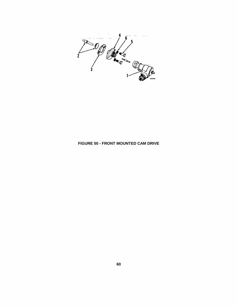
FIGURE 50 - FRONT MOUNTED CAM DRIVE
60

7.4000B TACHOMETER DRIVE
FIG/INDEX PART NO. NAME QTY
50- 1 5102049 ADAPTOR 150- 2 6454339 SHAFT(2.38''L.) 1
- 5123118 COVER ASSY.(INCLUDES STUDS) 1- 5155854 STUD(5/16''X1 3/32''L.) 2- 179857 BOLT, 7/16''-14X7/8'' 1
50- 3 5135935 GASKET 150- 4 5136249 ADAPTOR 150- 5 186647 BOLT, 1/4''-20X1'' 150- 6 103320 LOCKWASHER, 5/16'' AR
- 114493 NUT, 5/16''-24 HEX. 2
61

SECTION IV
SUPPLEMENTAL
OPERATING, MAINTENANCE
AND
REPAIR PARTS
INSTRUCTIONS

SUPPLEMENTAL OPERATING MAINTENANCE & REPAIR PARTS INSTRUCTIONSFOR
Roller, Vibratory, Self-propelled, Rexnord Model SP-848
Section I General Paragraph PagePurpose 1-1 1-1Scope 1-2 1-1CCE Item 1-3 1-1Description 1-4 1-1Operational Concept 1-5 1-1Procurement Status 1-6 1-1Equipment Publications 1-7 1-1Personnel & Training 1-8 1-2Logistics Assistance 1-9 1-2Warranty 1-10 1-2Reporting 1-11 2-1
Section II MaintenanceMaintenance Concept 2-1 2-1Maintenance Allocation Chart 2-2 2-1Modifications 2-3 2-2Equipment Improvement Recommendations 2-4 2-2Equipment Serviceability Criteria 2-5 2-2Maintenance Expenditure Limits 2-6 2-2Shipment & Storage 2-7 2-2Destruction to Prevent Enemy Use 2-8 2-2Fire Protection 2-9 2-2Basic Issue Item List 2-10 2-2Maintenance & Operating Supply List 2-11 2-3Special Tools & Equipment 2-12 2-3Maintenance Forms & Records 2-13 2-3Roll Over Protection System 2-14 2-3Towing Instructions 2-15Safety Precautions 2-16
Section III Repair Parts SupplyGeneral 3-1 3-1Prescribed Load List 3-2 3-1Authorized Stockage List 3-3 3-1Requisitioning Repair Parts 3-4 3-2Submitting Requisitions 3-5 3-2Rexnord Cross-reference Number System 3-6 3-3
i

Table of Contents Cont.
APPENDIXES PAGE
A Equipment Publications 4-1B Warranty Guidelines 4-2C Maintenance Allocation Chart 4-4D Modification Procedure 4-20E Basic Issue Items List 4-21F Maintenance & Operating Supply List 4-22G Rexnord Cross Reference Number System 4-23H Sample Format - DA Form 2765 Part Number Request 4-24I Sample Format - Milstrip Requisition for CCE (NSN) 4-25J Sample Format - Milstrip Requisition for CCE (Non-NSN) 4-26K Sample Format - Milstrip Requisition for CCE (Non-NSN) (Manual) 4-28L Prescribed Load List/Authorized Stockage List 4-30M Preventive Maintenance Checks and Service 4-31N Lubrication Chart 4-37
ii

SECTION I
GENERAL
1-1. Purpose. To provide User and Support personnel supplemental maintenance and repair parts instructions thathave special application to Commercial Construction Equipment (CCE) items.
1-2. Scope. This publication applies to Department of the Army Units, Organizations and Activities that use and/orsupport the CCE Self- Propelled Vibratory Roller, Rexnord Model SP-848.
1-3. CCE Item. The term "CCE Item" used in this publication applies to a standard commercial item of commercialequipment that has been approved for a specific TOE requirements and is procured and supported under the CCESystem Plan. This plan permits maximum utilization of the civilian construction industry's competitive research anddevelopment, manufacturer's equipment publications and commercial sources for repair parts.
1-4. Description. The CCE Vibratory Self-Propelled, High Impact, Single Smooth Drum Roller manufactured byRexnord Inc. is powered by an in-line three cylinder Detroit Diesel Engine. This engine (3-53 series) is used in otherconstruction equipment items currently in the Army System. Engine power is transmitted to the final drive by using ahydrostatic drive with a 2-speecd transmission. The steering is articulated, full power hydraulic type.
1-5. Operational Concept. The CCE Self-Propelled Vibratory Roller is intended for use in construction operations, i.e.,road construction and repair, airfield and port construction. Primary tasks are compacting new road beds of soil, sand orgravel preparatory to laying of asphalt pavements. Secondary uses are compaction of pavement base courses andstabilized bases.
1-6. Procurement Status. The procurement contract number is DLA700-78-C-8327 and was awarded on 21 Sep 78 fora total of 64 units.
1-7. Equipment Publications.
a. Initially two sets of the manufacturer's commercial publications will be overpacked and shipped with eachRoller (reference Appendix A).
b. The overpacked publications are located in the tool box built into the Roller frame.
1-1

1-8. Personnel and Training.
a. MOS Requirements:
(1) Operator: 62J, General Construction Equipment Operator.
(2) Organizational Maintenance: 62B, Engineer Equipment Repairman.
(3) Direct and General Support Maintenance: 62B, Engineer Equipment Repairman; 63G, Fuel andElectrical Systems Repairman, 44B, Metal Body Repairman.
b. New Equipment Training: New Equipment Training Teams (NETTs) are available to major field commands.Requests for NETTs should be forwarded to Commander, US Army Tank-Automotive Materiel Readiness Command(TARCOM), ATTN: DRSTA-MLT, Warren, MI 48090. Training teams should be requested only when trained personnelare not available in the command to operate and/or maintain the Roller.
1-9. Logistics Assistance.
a. Tank-Automotive Command Field Maintenance Technicians stationed at CONUS and OCONUS installationswill be fully qualified and available to furnish on-site training and or assistance concurrent with receipt of the Roller.
b. Assistance can be obtained by contacting the Logistics Assistance Office listed in Appendix B of AR 700-4.
1-10. Warranty. The CCE Roller contractor warrants the products furnished under this contract according to the termsand conditions described in the equipment publications and Appendix B of this publication. All warranties furnished tothe Roller contractor by subcontractors of assemblies or components utilized in the manufacture of the end item will beextended to the Government. See Appendix B for warranty guidelines.
1-2

1-11. Reporting. You can improve this publication by recommending improvements, using DA Form 2028(Recommended Changes to Publications and Blank Forms) and mail direct to Commander, US Army Tank-AutomotiveMateriel Readiness Command, ATTN: DRSTA-MVB, Warren, MI 48090.
SECTION II
MAINTENANCE
2-1. Maintenance Concept. The CCE Roller will not require any new or special maintenance considerations. Allmaintenance functions can be accomplished within the current maintenance concepts established for constructionequipment.
a. Operator/Crew Maintenance: Operator and crew maintenance is limited to daily preventive maintenancechecks and services.
b. Organizational Maintenance: Organizational maintenance consists of scheduled preventive maintenanceservices, minor repairs and adjustments.
c. Direct Support Maintenance: Direct Support Maintenance consists of repairs on-site or in a direct supportunits shops. Repairs are accomplished with a minimum of tools and test equipment; the assemblies and end items thusrepaired are returned to their users.
d. General Support Maintenance: General support maintenance overhauls selected assemblies and repairsitems designated by the area support command for return to stock.
e. Depot Maintenance: Depot maintenance overhauls end items and selected major assemblies when they arerequired to satisfy overall Army requirements. Overhaul of the end item may also be performed by contract with themanufacturer.
2-2. Maintenance Allocation Chart. Maintenance will be performed as necessary by the category indicated in theMaintenance Allocation Chart (MAC) (Appendix C) to retain or restore serviceability. All authorized maintenance withinthe capability of a using organization will be accomplished before referring the item to support maintenance. Highercategories will perform the maintenance functions of lower categories when required or directed by the appropriateCommanders. Using and support units may exceed their authorized scope and functions in the MAC when approval isgranted by the next higher support maintenance Commander.
2-1

2-3. Modifications. Modifications will be accomplished by the end item manufacturer after TARCOM approves thefield campaign or modification plan. See appendix D.
2-4. Equipment Improvement Recommendations (EIR). Equipment Improvement Recommendations will be submittedin accordance with TM 38-750.
2-5. Equipment Serviceability Criteria (ESC). Equipment Serviceability Criteria are not applicable to the Roller (AR750-1).
2-6. Maintenance Expenditure Limits. The average life expectancy for the Roller is 15 years.
PERCENT OF REPAIR YEAR
50% 198445% 198640% 198835% 199030% 199220% 199410% 1995
2-7. Shipment and Storage.
a. Shipment and Storage. Refer to TB 740-94-2 for procedures covering preservation of equipment forshipment and storage.
b. Administrative Storage. Refer to TM 740-90-1 for instructions covering administrative storage of equipment.
2-8. Destruction to Prevent Enemy Use. Refer to TM 750-244-3 for procedures covering destruction of equipment toprevent enemy use.
2-9. Fire Protection.
a. A hand operated fire extinguisher may be installed at the discretion of the using unit.
b. Approved hand-portable fire extinguishers are listed in TB 5-4200-200-10.
2-10. Basic Issue Items List (BIIL). See Appendix E for a list of items which accompany the end item or are required foroperation and/or operator's maintenance.
2-2

2-11. Maintenance and Operating Supply List. See Appendix F for a list of maintenance and operating suppliesrequired for initial operation.
2-12. Special Tools and Equipment. No special tools or equipment are required for operation and maintenance of theRoller.
2-13. Maintenance Forms and Records. Operational maintenance and historical records will be maintained as requiredby the current TM 38-750.
2-14. Roll Over Protection System (ROPS). ROPS is available for the Model SP-848 roller from Rexnord Inc. in a kitform. Commanders will refer to AR 385-55, paragraph 7-9. Additional safety devices, when modifications, are required.
2-15. Towing Instructions.
a. Before towing a unit that has malfunctioned, ensure that the Forward-Reverse and Vibration Levers are inthe neutral positions and that the parking brake has been released.
b. Tow the unit only when necessary and at speeds of one to two miles per hour for as short a distance aspossible.
2-16. Safety Precautions. Always observe the following safety precautions to prevent possible injury to personnel anddamage to the equipment.
a. TRAINED OPERATORS ONLY.
b. Always use slower unit speeds and added caution when operating close to a lift edge or when travelingdownhill.
c. Never travel across a slope. Always travel up or down a slope.
d. Always engage the parking brake before dismounting the unit.
e. Never shut down the engine when traveling up or down a slope. Always move the Forward-Reverse Levertoward neutral to apply hydrodynamic braking.
f. KEEP CLEAR OF HITCH AREA when unit is operational. Hitch area closes when unit is turned.
2-3

SECTION III
REPAIR PARTS SUPPLY
3-1. General.
a. The basic policies and procedures in AR 710-2 and AR 725-50 are generally applicable to repair partsmanagement for CCE items.
b. Manufacturer's parts manuals are furnished with CCE items instead of Department of the Army Repair Partsand Special Tool List (RPSTL).
c. National Stock Numbers (NSN's) are initially assigned only to PLL/ASL parts and major assemblies, i.e.,engines, transmissions, etc. Additional NSN's are assigned by the supply support activities as demands warrant.
d. Automated Processing (AUTODIN) of Federal Supply Code Manufacturer (FSCM) part number requisitions,without edit for matching NSN's and exception data, is authorized.
e. Proper use of project codes and weapons systems designator codes on parts requisitions is essential.
f. Repair parts are available from commercial sources and may be purchased locally in accordance with AR710-2 and AR 734-110.
g. Initial Prescribed Load List (PLL) and Authorized Stock List (ASL) will be distributed by US Army Tank-Automotive Materiel Readiness Command (TARCOM), ATTN: DRSTA-FH.
3-2. Prescribed Load List (PLL). The PLL distributed by TARCOM is an estimated 15 days supply recommended forinitial stockage at organizational maintenance. Management of PLL items will be governed by the provisions of AR 710-2 and local command procedures. Selection of PLL parts for shipment to CONUS/OCONUS units is based upon thereceiving command's recommendation after their review of the TARCOM prepared list. Organizations and activities inCONUS/OCONUS will establish PLL stocks through normal requisitioning process.
3-3. Authorized Stockage List (ASL). The ASL distributed by TARCOM is an estimated 45 days supply of repair partsfor support units and activities. The ASL parts will be shipped according to the recommendations of the receivingcommands, after they have reviewed the initial list distributed by TARCOM. Support units and activities inCONUS/OCONUS will establish ASL stocks through normal requisitioning process.
3-1

3-4. Requisitioning Repair Parts.
a. Using Units/Organizations: Requisitions (DA Form 2765 Series) will be prepared according to AR 710-2 andlocal command directives. All requisitions will have the Weapons System Designator Code "87" (interim change 5-1, AR710-2, per DA message, DALO-SMS, 091400Z June 1978) entered in the 2nd and 3rd positions of block 18. Units inCONUS will use Project Code "BGW" in block 19. Units OCONUS will enter in block 19 Project Code "JZC", seeAppendix H.
b. Support Units and Activities:
(1) General: ALL MILSTRIP requisitions (DD Form 1348 Series) prepared for repair parts support of CCEitems will include distribution and project codes, see Appendixes I, J and K.
(2) Distribution Code: Supply Customers in CONUS will use code "F" in card column 54. CustomersOCONUS will use the appropriate code from Appendix P, paragraph P-3a(1), AR 725.50. Weapons System DesignatorCode "87" (DA Message DALO-SMS, 091400Z Jun 78) will be entered in card columns 55 and 56 of all requisitions.
(3) Project Codes: The applicable project code will be entered in card columns 57-59 of requisitions fornon-NSN parts, whether CONUS or OCONUS customers. The Project Code "BGW" will be used by CONUS customerswhen requisitioning part numbered parts. Supply customers OCONUS will use Project Code "JZC" for part numberedparts.
3-5. Submitting Requisitions.
a. Using Units and Organizations will submit DA Form 2765 Series requisitions to designated support units oractivities in accordance with local procedures.
b. Support units and activities will forward MILSTRIP requisitions for NSN parts through the Defense AutomatedAddressing System (DAAS) to the Managing Supply Support Activity. Requisitions for part numbered parts will beforwarded through DAAS to the Defense Construction Supply Center (DCSC).
NOTE: When the manufacturer's part number and Federal Supply Code for Manufacturer (FSCM) exceed the space incard columns 8 through 22 of A02/AOB requisitions, prepare an A05/AOE requisition (DD Form 1348-6) and mail it toCommander, Defense Construction Supply Center, ATTN: DCSC-OSR, Columbus, Ohio 43215.
3-2

3-6. Rexnord Cross Reference Number System. An explanation of Rexnord Prefix and Suffix Is available inAppendix G.
3-3

APPENDIX A
PUBLICATIONS
DA EQUIPMENT PUBLICATIONS
NOMENCLATURE EQUIPMENT PUBLICATION NUMBER DATEAVAILABLE
Utilization of Engineer ConstructionEquipment: Volume A, Earthmoving,Compaction, Grading and DitchingEquipment.
TM5-331A 18 Aug 67
Charging System Trouble Shooting(The Easy Way)
DA Pamphlet 750-53 Dec 1976
*NOTE*
Supervisors and operators should refer to TM5-311A to get the most use from this equipment.
OTHER THAN OFFICIAL DA EQUIPMENT PUBLICATIONS
NOMENCLATURE EQUIPMENT PUBLICATIONNUMBER OR TYPE
DATEAVAILABLE
SOURCE OFSUPPLY
NONE
4-1

APPENDIX B
WARRANTY GUIDELINES
NO
DISTRIBUTOR CONTACT
1. A warranty period of 15 months applies to Self-Propelled Model SP-848 Vibratory Rollers, contract numberDLA700-78-C-8327, manufactured by Rexnord Inc. after delivery to the Government. This warranty applies to the enditem components and all supplies furnished under the contract.
2. Using units may not contact their local dealer. You must mail DA Form 2407 to the Maintenance Directorate,TARCOM, at the following address: US Army Tank-Automotive Materiel Readiness Command, ATTN: DRSTA-MVB,Warren, Michigan 48090. To expedite actions you may call the Information to AUTOVON 273-3387, 3383 or 3439 withthe information from your DA 2407, Section 1, Block 1 through 11, Blocks 16, 17, 18 and 20.
3. General Information:
a. DA Form 2407 (prepared in accordance with warranty claim actions in TM 38-750) will be used to submitwarranty claims actions for end items when components, parts or assemblies are defective and are covered by amanufacturer's warranty. End items under warranty are identified by a decal plate and/or warranty statement included inthe operator's and maintenance manual for the end item. All warranty actions settle or unsettled will be reported to theNational Maintenance Point (NMP) on DA Form 2407. For warranties settled locally the DA Form 2407 will contain astatement "For Information Only" in block 35.
b. Maintenance activities in support of organizational maintenance are the responsible points of contactbetween the originator of warranty claims and the National Maintenance Point (US Army Tank-Automotive MaterielReadiness Command, DRSTA-MVB, AUTOVON 273-3387, 3383 or 3439, Warren, Michigan 48090), which serves as theDA Representative with the contractor in warranty matters.
NOTE: In certain instances, the originating organization and the support activity are one and the same.
c. Before you take your equipment to a dealer for repair, whether or not it was necessary for you to go throughthe NMP (TARCOM), check with your local procurement office to see if a funds commitment document is needed.Sometimes, even though the majority of the repairs are covered by the warranty, there may be a small charge for normalmaintenance costs, i.e., oil filters, oil etc. Further the cause of damage could be determined by the dealer to be directlyrelated to "operator abuse." In that case, the Government may be obligated to pay for teardown services even if
4-2

the repairs are no longer desired, or for the complete cost if repairs are to be completed by the dealer.
d. When the equipment is given to the dealer for repairs, find out how long the work will take, the extent of theproblem if possible, and the charges, if any, which may be involved. Leave the name and telephone number of theperson to be contacted for pickup of the equipment and specifically state that he should be called as-soon as the repairsare finished. In addition state he should be telephoned if unexpected problems, costs and/or delays are encountered.Get the name and telephone number of the Service Manager, for any required follow-up purposes.
e. When you arrive to pickup your equipment after completion of services, make certain that you know exactlywhat repairs were performed and/or parts replaced. This is required for overall problem trend evaluation by the NMP andmust be identified upon completion of warranty services.
f. Telephone the NMP at TARCOM, AUTOVON 273-3387, 3383 or 3439. If:
(1) Your equipment requires repairs and you cannot obtain these services using the procedures listedabove.
(2) The length of time required for repairs may seriously hamper your mission, or if the dealer's overallresponse to your requirements are not satisfactory.
(3) You have any questions regarding warranty procedures - either in general or about a specific job. Donot wait until your problems become critical.
g. Do not attempt to conduct negotiations regarding a breach of warranty. This is a function of the ContractingOfficer, through the NMP at TARCOM.
4-3

APPENDIX C
MAINTENANCE ALLOCATION CHART
FOR
ROLLER, VIBRATORY, SELF-PROPELLED
Section I. INTRODUCTION
1. General: This Maintenance Allocation Chart designates responsibility for performance of Maintenance functions tospecific Maintenance categories.
2. Maintenance functions:
a. Inspect: To determine the serviceability of an item by comparing its physical, mechanical and/or electricalcharacteristics with established standards through examination.
b. Test: To verify serviceability and detect Incipient failures by measuring the mechanical or electricalcharacteristics of an item and comparing those characteristics with prescribed standards.
c. Service: Operations required periodically to keep an item in proper operating condition, i.e., to clean(decontaminate), to preserve, to drain, to paint, or to replenish fuel, lubricants, hydraulic fluids, or compressed airsupplies.
d. Adjust: To maintain, within prescribed limits, by bringing into proper or exact position, or by setting theoperating characteristics to specified parameters.
e. Align: To adjust specified variable elements of an item to bring about optimum or desired performance.
f. Calibrate: To determine and cause corrections to be made or to be adjusted on instruments or test measuringand diagnostic equipment used in precision measurement. Consists of comparisons of two instruments, one of which is acertified standard of known accuracy, to detect and adjust any discrepancy in the accuracy of the instrument beingcompared.
g. Install: The act of emplacing, seating or fixing into position an item, part, or module (component orassembly5 in a manner to allow the proper functioning of an equipment or system.
h. Replace: The act of substituting a serviceable like type part, subassembly, or module (component orassembly) for an unserviceable counterpart.
i. Repair: The application of maintenance services or other maintenance actions to restore serviceability to anitem by correcting specific damage, fault, malfunction, or failure in a part, subassembly, module (component orassembly), and item, or system.
4-4

j. Overhaul: That maintenance effort (service/action) necessary to restore an item to a completelyserviceable/operational condition as prescribed by maintenance standards (i.e., DMWR) in appropriate technicalpublications. Overhaul is normally the highest degree of maintenance performed by the Army. Overhaul does notnormally return an item to like new condition.
k. Rebuild: Consists of those services/actions necessary for the restoration of unserviceable equipment to a likenew condition in accordance with original manufacturing standards. Rebuild is the highest degree of materielmaintenance applied to Army equipment. The rebuild operation includes the act of returning to zero those agemeasurements (hours/miles, etc.) considered in classifying Army equipments/components.
3. Column entries: Columns used in the Maintenance allocation chart are explained below:
a. Column 1, Group Number: Column 1 lists group numbers, the purpose of which is to identify components,assemblies, subassemblies, and modules with the next higher assembly.
b. Column 2, Component/Assembly: Column 2 contains the noun names of components, assemblies,subassemblies, and modules for which maintenance is authorized.
c. Column 3, Maintenance Functions: Column 3 lists the functions to be performed on the item listed inColumn 2.
d. Column 4, maintenance Category: Column 4 specifies, by the listing of a "work time" figure in theappropriate subcolumn(s), the lowest level of maintenance authorized to perform the function listed in Column, 3. Thisfigure represents the active time required to perform that maintenance function at the indicated category of maintenance.If the number or complexity of the tasks within the listed maintenance function vary at different maintenance categories,appropriate "work time" figures ill be shown for each category. The number of man-hours specified by the "work time"figure represents the average time required to restore an item (assembly, subassembly, component, module, end item orsystem) to a serviceable condition under typical field operating conditions. This time includes preparation time,troubleshooting time, and quality assurance/quality control time in addition to the time required to perform the specifictasks identified for the maintenance functions authorized in the Maintenance Allocation Chart.
e. Columns 5, Tools and Equipment: Column 5 specifies by code those common tool sets (not individual tools)and special tools, test, and support equipment required to perform the designated function.
f. Column 6, Remarks: Column 6 contains an alphabetic code which leads to the remark in Section IV,Remarks, which is pertinent to the item opposite the particular code.
4-5

Section II . MAINTENANCE: ALLOCATION CHARTROLLER, VIBRATORY, SELF-PROPELLED HIGH IMPACT
SINGLE SMOOTH DRUM (CCE)
(1)GROUP
(3) (3)MAINTENANCE
(4)MAINTENANCE CATEGORY
(5)TOOLS
(6)
NUMBER COMPONENT/ASSEMBLY FUNCTION C O F H D ANDEQUIPMENT
REMARKS
01 ENGINE
0100 Engine Assembly Test 2.0 1,2,3
Service 0.1
Replace 16.0
Repair 21.0
Overhaul 48.0
Engine Mounts Replace 3.0
0101 Cylinder Block Test 5.0 1,2,3
Replace 4.0
Repair 20.0
Cylinder Sleeve Replace 3.0
Cylinder Head Replace 4.0
Repair 4.0
Overhaul 8.0
0102 Crankshaft Replace 5.0 1,2,3
Main Bearings Replace 4.0
Drive Pulley Replace 2.0
0103 Flywheel Replace 3.0 1,2,3
0104 Pistons & Connecting Rods Repair 3.0
Replace 2.0 1,2,3
*The subcolumns are as follows:C - operator/crewO - organizationalF - direct supportH - general supportD - depot
**Worktimes are included in DMWR
4-6

Section II . MAINTENANCE: ALLOCATION CHARTROLLER, VIBRATORY, SELF-PROPELLED HIGH IMPACT
SINGLE SMOOTH DRUM (CCE)
(1)GROUP
(3) (3)MAINTENANCE
(4)MAINTENANCE CATEGORY
(5)TOOLS
(6)
NUMBER COMPONENT/ASSEMBLY FUNCTION C O F H D ANDEQUIPMENT
REMARKS
Rings and Bearing Replace 0.5
0105 Rocket Arms Replace 0.5 1, 2
Valve Springs Test 0.8
Replace 0.3
Valves, Exhaust Adjust 2.0
Replace 1.0
Repair 2.0
Camshaft, bearings, andgears Replace 4.0
0106 Oil Cooler Service .2 1, 2
Replace 1.0
Oil Pan Replace 1.5
Repair 1.0
Oil Pump Replace 0.8
Repair 2.0
Oil Pressure Regulator Adjust 0.2
Replace 0.5
Oil Filter Assy Service 0.2
Replace 1.0
*The subcolumns are as follows:C - operator/crewO - organizationalF - direct supportH - general supportD - depot
**Worktimes are included in DMWR
4-7

Section II. MAINTENANCE: ALLOCATION CHARTROLLER, VIBRATORY, SELF-PROPELLED HIGH IMPACT
SINGLE SMOOTH DRUM (CCE)
(1)GROUP
(3) (3)MAINTENANCE
(4)MAINTENANCE CATEGORY
(5)TOOLS
(6)
NUMBER COMPONENT/ASSEMBLY FUNCTION C O F H D ANDEQUIPMENT
REMARKS
Oil Filter Element Replace 0.5
0108 Exhaust Manifold Replace 1.0 1,2,3
Repair 1.0
03 FUEL SYSTEM
0301 Fuel Injector Test 1.0 1,2,3
Replace 1.0
0302 Fuel Pump Replace 1.0 1,2
Repair 1.0
0304 Air Cleaner Service 0.4 1
Replace 1.0
Repair 0.5
Air Cleaner Element Replace 0.5
0305 Blower Air Intake Service 0.3 1
Replace 1.0
Repair 2.0
Air Shut-Down Adjust 0.5
Replace 1.5
Repair 2.0
0306 Fuel Tank Service 0.2 1,2
Replace 1.5
Repair 2.0
*The subcolumns are as follows:C - operator/crewO - organizationalF - direct supportH - general supportD - depot
**Worktimes are included in DMWR
4-8
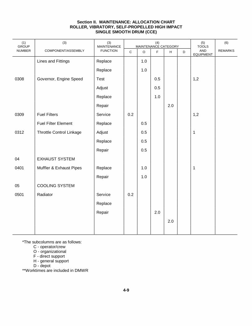
Section II. MAINTENANCE: ALLOCATION CHARTROLLER, VIBRATORY, SELF-PROPELLED HIGH IMPACT
SINGLE SMOOTH DRUM (CCE)
(1)GROUP
(3) (3)MAINTENANCE
(4)MAINTENANCE CATEGORY
(5)TOOLS
(6)
NUMBER COMPONENT/ASSEMBLY FUNCTION C O F H D ANDEQUIPMENT
REMARKS
Lines and Fittings Replace 1.0
Replace 1.0
0308 Governor, Engine Speed Test 0.5 1,2
Adjust 0.5
Replace 1.0
Repair 2.0
0309 Fuel Filters Service 0.2 1,2
Fuel Filter Element Replace 0.5
0312 Throttle Control Linkage Adjust 0.5 1
Replace 0.5
Repair 0.5
04 EXHAUST SYSTEM
0401 Muffler & Exhaust Pipes Replace 1.0 1
Repair 1.0
05 COOLING SYSTEM
0501 Radiator Service 0.2
Replace
Repair 2.0
2.0
*The subcolumns are as follows:C - operator/crewO - organizationalF - direct supportH - general supportD - depot
**Worktimes are included in DMWR
4-9

Section II. MAINTENANCE: ALLOCATION CHARTROLLER, VIBRATORY, SELF-PROPELLED HIGH IMPACT
SINGLE SMOOTH DRUM (CCE)
(1)GROUP
(3) (3)MAINTENANCE
(4)MAINTENANCE CATEGORY
(5)TOOLS
(6)
NUMBER COMPONENT/ASSEMBLY FUNCTION C O F H D ANDEQUIPMENT
REMARKS
0503 Thermostat Replace 1.0 1
Hoses and Clamps Replace 0.5
0504 Water Pump Replace 2.0 1
Repair 1.0
0505 Fan Assembly Replace 1.0 1
Repair 1.0
Fan Guard Replace 1.0
Repair 1.0
Fan Belts Inspect 0.1
Adjust 0.5
Replace 1.0
06 ELECTRICAL SYSTEM
0601 Alternator Test 0.5 1,5
Replace 0.6
Repair 1.5
0603 Starting Motor Test 0.5
Replace 1.0 1,5
Repair 1.5
Adjust 0.5
Replace 1.0
*The subcolumns are as follows:C - operator/crewO - organizationalF - direct supportH - general supportD - depot
**Worktimes are included in DMWR
4-10

Section II. MAINTENANCE: ALLOCATION CHARTROLLER, VIBRATORY, SELF-PROPELLED HIGH IMPACT,
SINGLE SMOOTH DRUM (CCE)
(1)GROUP
(3) (3)MAINTENANCE
(4)MAINTENANCE CATEGORY
(5)TOOLS
(6)
NUMBER COMPONENT/ASSEMBLY FUNCTION C O F H D ANDEQUIPMENT
REMARKS
0607 Instrument Panel Accessories Replace 0.5 1
Repair 0.5
0608 Miscellaneous ElectricalItems (switches, circuitbreakers, etc.) Replace 0.5 1
Repair 0.5
0609 Headlight Assembly Replace 0.3 1
Repair 0.5
Headlight Lamp Units Replace 0.3
0610 Sending Units/warningswitches Replace 0.5
1
0611 Horn Assembly Replace 0.5 1
Repair 0.5
0612 Battery Test 0.3 1
Inspect 0.1
Service 0.2
Replace 0.5
Battery Cables Replace 0.4
Repair 0.5
0613 Wiring Harness Replace 1.0 1
Repair 0.5 5
*The subcolumns are as follows:C - operator/crewO - organizationalF - direct supportH - general supportD - depot
**Worktimes are included in DMWR
4-11

Section II. MAINTENANCE: ALLOCATION CHARTROLLER, VIBRATORY, SELF-PROPELLED HIGH IMPACT
SINGLE SMOOTH DRUM (CCE)
(1)GROUP
(3) (3)MAINTENANCE
(4)MAINTENANCE CATEGORY
(5)TOOLS
(6)
NUMBER COMPONENT/ASSEMBLY FUNCTION C O F H D ANDEQUIPMENT
REMARKS
07 TRANSMISSION SYSTEM
0700 Transmission Assembly Test 1.0 1,2
Service 0.5
Replace 4.0
Repair 16.0
Overhaul 20.0
0705 Gear Range Control Service 0.3 1
Adjust 0.5
Replace 2.0
Repair 2.0
0721 Hydraulic Oil Reservoir Service 0.3 1,2
Replace 3.0
Repair 3.0
Hydraulic Oil Filter Replace 1.0
Hydrostatic Pump(Propelling) Replace 2.0
Repair 2.0
Overhaul 4.0
Hydrostatic Motor (propelling) Replace 1.5
Repair 2.0
*The subcolumns are as follows:C - operator/crewO - organizationalF - direct supportH - general supportD - depot
**Worktimes are included in DMWR
4-12

Section II. MAINTENANCE: ALLOCATION CHARTROLLER, VIBRATORY, SELF-PROPELLED HIGH IMPACT
SINGLE SMOOTH DRUM (CCE)
(1)GROUP
(3) (3)MAINTENANCE
(4)MAINTENANCE CATEGORY
(5)TOOLS
(6)
NUMBER COMPONENT/ASSEMBLY FUNCTION C O F H D ANDEQUIPMENT
REMARKS
Overhaul 4.0
Hydraulic Oil Cooler Service 0.2
Replace 2.0
Repair 2.0
Direction/speed controlassembly Service 0.5
Adjust 1.0
Replace 2.0
Repair 2.0
Pressure Relief Valve Replace 1.0
Lines and Fittings Replace 1.0
Repair 1.0
08 VIBRATORY DRIVESYSTEM
0801 Hydrostatic pump (Vibratory) Replace 2.0 1,2
Repair 2.0
Overhaul 4.0
Jack Shaft, Bearings,Coupling and Sheave Replace 2.0
Repair 2.0
Driven Sheave Assy Replace 3.0
Repair 3.0
*The subcolumns are as follows:C - operator/crewO - organizationalF - direct supportH - general supportD - depot
**Worktimes are included in DMWR
4-13

Section II. MAINTENANCE: ALLOCATION CHARTROLLER, VIBRATORY, SELF-PROPELLED HIGH IMPACT
SINGLE SMOOTH DRUM (CCE)
(1)GROUP
(3) (3)MAINTENANCE
(4)MAINTENANCE CATEGORY
(5)TOOLS
(6)
NUMBER COMPONENT/ASSEMBLY FUNCTION C O F H D ANDEQUIPMENT
REMARKS
Eccentrie Shaft Assy Service 0.2
Replace 8.0
Repair 8.0
Vibratory Control Assy Service 0.5
Adjust 1.0
Replace 2.0
Repair 1.0
09 PROPELLER SHAFT'
0900 Propeller Shaft Assy Service 0.4 1
Replace 1.5
Repair 1.0
11 REAR AXLE
1100 Rear Axle Assy Service 0.5 1
Replace 8.0
Repair 8.0
1102 Differential Assy Service 0.5 1,2
Replace 8.0
Repair 8.0
12 BRAKES
1201 Parking Brake Assy Replace 1.0
Repair 1.0 1
*The subcolumns are as follows:C - operator/crewO - organizationalF - direct supportH - general supportD - depot
**Worktimes are included in DMWR
4-14

Section II. MAINTENANCE: ALLOCATION CHARTROLLER, VIBRATORY, SELF-PROPELLED HIGH IMPACT
SINGLE SMOOTH DRUM (CCE)
(1)GROUP
(3) (3)MAINTENANCE
(4)MAINTENANCE CATEGORY
(5)TOOLS
(6)
NUMBER COMPONENT/ASSEMBLY FUNCTION C O F H D ANDEQUIPMENT
REMARKS
1202 Service Brakes Replace 1.0
Repair 1.0
1204 Master Cylinder Service 0.2 1
Replace 2.0
Repair 1.0
Lines and Fittings Replace 2.0
Repair 1.0
13 WHEELS
1311 Wheel Assembly Inspect 0.5 1
Replace 1.5
Hubs, Bearings & Seals Service 0.5
Adjust 1.0
Replace 2.0
1313 Tires Inspect 0.2
Replace 2.0
Repair 2.0
14 STEERING
1401 Steering Wheel Replace 1.0 1
1407 Steering Control Unit Test 1.0 1,2
Replace 2.0
*The subcolumns are as follows:C - operator/crewO - organizationalF - direct supportH - general supportD - depot
**Worktimes are included in DMWR
4-15

Section II. MAINTENANCE: ALLOCATION CHARTROLLER, VIBRATORY, SELF-PROPELLED HIGH IMPACT,
SINGLE SMOOTH DRUM (CCE)
(1)GROUP
(3) (3)MAINTENANCE
(4)MAINTENANCE CATEGORY
(5)TOOLS
(6)
NUMBER COMPONENT/ASSEMBLY FUNCTION C O F H D ANDEQUIPMENT
REMARKS
Repair 4.0
1410 Hydraulic Steering Pump Service 0.5 1,2
Replace 2.0
Repair 4.0
1411 Hoses Lines and Fittings Inspect 0.5
Replace 1.0
Repair 1.0
1412 Hydraulic Steering Cylinders Service 0.5 1,2
Replace 1.5
Repair 2.0
15 FRAME
1501 Power Unit Frame Repair 3.0 1,2
Roll Frame Assy Repair 3.0
18 BODY, HOOD & COWLING
1801 Hood and Cowling Replace 1.0 1,2
Repair 2.0
1806 Seat Assembly Adjust 0.1 1,2
Replace 1.0
Repair 1.0
*The subcolumns are as follows:C - operator/crewO - organizationalF - direct supportH - general supportD - depot
**Worktimes are included in DMWR
4-16

Section II. MAINTENANCE: ALLOCATION CHARTROLLER, VIBRATORY, SELF-PROPELLED HIGH IMPACT
SINGLE SMOOTH DRUM (CCE)
(1)GROUP
(3) (3)MAINTENANCE
(4)MAINTENANCE CATEGORY
(5)TOOLS
(6)
NUMBER COMPONENT/ASSEMBLY FUNCTION C O F H D ANDEQUIPMENT
REMARKS
1808 Tool Box Repair 0.8 1,2
74 EARTH MOVINGEQUIPMENTCOMPONENTS
7466 Roll Scrapers Service 0.5 1
Replace 1.5
Repair 1.0
*The subcolumns are as follows:C - operator/crewO - organizationalF - direct supportH - general supportD - depot
**Worktimes are included in DMWR
4-17

MAINTENANCE ALLOCATION CHART FOR
ROLLER, VIBRATORY, SELF-PROPELLED HIGH IMPACTSINGLE SMOOTH DRUM (CCE)
SECTION III - TOOL AND TEST EQUIPMENT REQUIREMENTS
TOOL OR TESTEQUIPMENTREFERENCE
CODEMAINTENANCE
CATEGORY
NOMENCLATURE NATIONAL/NATOSTOCK NUMBER TOOL
NUMBER
Unless otherwise noted, all maintenance functionscan be accomplished with the tools contained inthe following common two sets.
1 O, F, H Shop Equip Contact Maint. 4940-00-294-9518 T10138TRK MTD (SC 4940-97-CL-E-05)
1 O, F, H Shop Equip Org Repair, 4940-00-294-9516 T13152Light TRK MTD (SC 4940-97-
1 O, F, H Tool Kit Automotive Maint, 4910-00-754-0654 W32593Org Maint Common #1 (SC4910-95-CLA74)
1 O, F, H Tool Kit Automotive Maint, 4910-00-754-0650 W32730Org Maint Common #2 (SC4910-95-L-A72)
1 O, F, H Tool Kit, Light Weight (SC 5180-00-177-7033 W330045180-90-CLW26)
1 O, F, H Shop Equip Auto Maint and 4910-00-754-0653 W32867Repair Org Maint Supp #1(SC 4910-95-C-A73)
1 O, F, H Shop Equip Welding Field 3470-00-357-7268 T16714Maint (SC 3470-95-CL-A08)
1 O, F, H Tool Set, Veh Full Trackec 4940-00 -754-0743 W65747Sugg #2 SC 4940-95-CL-AO8
2 F, H Shop Equip Gen Purp Repair 494-00-287-4894 T10549Semitrlr MTD (SC 4940-97-
2 F, H Tool Kit Automotive, Fuel 4910-00-754-0655 W32456and Elec Sys Repair (SC491095-CL-A50)
2 F, H Tool Kit, Master Mechanic 5180-00-699-5273 W45060and Equip Maint and Repair
STA Form 1 Feb 76 4801A PREVIOUS EDITIONS OF THIS FORM MAY BE USED
4-18

MAINTENANCE ALLOCATION CHART FOR
ROLLER, VIBRATORY, SELF-PROPELLED HIGH IMPACTSINGLE SMOOTH DRUM (CCE)
SECTION III - TOOL AND TEST EQUIPMENT REQUIREMENTS
TOOL OR TESTEQUIPMENTREFERENCE
CODEMAINTENANCE
CATEGORY
NOMENCLATURE NATIONAL/NATOSTOCK NUMBER TOOL
NUMBER
2 F, H Shop Set, Fuel and Elec 4910-00-754-0714 T30414Sys Field Maint Basic (SC4910-95-C-A01)
2 F, H Shop Set, Fuel and Elec 4910-00-390-7775 T30688Sys Field Maint Basic Sup#2 (SC 4910-95-C-A65)
2 F, H Shop Equip Machine Shop, 3470-00-754-0708 T15644Field Maint Basic (SC3470-95-CLA02)
2 F, H Measuring and Lay Out Tool 5280-00-511-1950 W4,512Set Mach (SC 52895-CL
2 F, H Tool Kit Body and Fender 5180-00-75-0643 W33689Repair
3 F, H Wrench Set Socket, 3/4" 5310-00-754-0743 W65747Drive Hex Type
4 O, F, H Wrench Torque, 3/4" Drive 5120-00-5425577 Y84966500 lb Cap
5 O, F, H Multimeter 6625-00-999-7465 M8D242
STA Form 1 Feb 76 4801A PREVIOUS EDITIONS OF THIS FORM MAY BE USED
4-19

APPENDIX D
4-20

APPENDIX E
BASIC ISSUE ITEMS LIST
NOMENCLATURE:MANUFACTURERSERIAL NUMBER RANGE: DATE.
(1)
MFR PART NO.
(2)
MFR FED CODE
(3)
DESCRIPTION
(4)
UNIT OF ISSUE
(5)QUANTITY
FURNISHEDW/EQUIP
298-316-47 53786 Grease Gun Ea 1
ITEMS TROOP INSTALLED OR AUTHORIZED LIST
(1) (2) (3)DESCRIPTION
(4) (5)
SMR NATIONAL STOCKNUMBER
REF No & MFRCODE
USABLEON CODE
UNITOF
MEAS
QTYAUTH
NOTE: The following items are overpacked with theRoller
7520-00-559-9618 Case, Cotton Duck: MIL-B-11743 (81349) ea 1
7510-00-889-3494 Log Book Binders MIL-B-43064 ea 1
NOTE: The following items are authorized but not issuedwith the Roller.
4210-00-889-2221 Extinguisher, Fire Dry Chemical ea 1
4-21

APPENDIX F
MAINTENANCE AND OPERATING SUPPLY LIST
NOMENCLATURE: Roller, Vibratory, Self Propelled MAKE: Rexnord Inc. MODEL: SP-848
MFR PART NO.SP-848
NSN:3895-01-075-2823
SERIAL NO. RANGE:-----TO -----
DATE:June 79
(1)
COMPONENTAPPLICATION
(2)MFR PART NO.
ORNAT'L STOCK NO.
(3)
DESCRIPTION
(4)QTY REQF/INITIAL
OPN
(5)QTY REQF/8 HRS
OPN
(6)
NOTES
Engine Crankcase 9150-00-188-9858 Oil, Lubricating OE/H030MlL-L-2104C
14 Qts 0 General Suc: 5 gal
9150-00-186-6668 Oil, Lubricating OE/HD010MIL-L-2104C
14 Qts 0 Low Temp: 5 gal
Brake MasterCylinder 9150-03-949-7602 Brake Fluid Automotive VV-B-680 1 Pt. 0
Two SpeedTransmission
9150-01-035-5393
Axle Differential 9150-01-035-5393
Planetary WheelEnds 9150-01-035-5393 Gear Lubricating Oil/G080-90 9 ½ Qts 0 Temp Range - 30F and up
Hydraulic OilSystem 9150-00-657-4959 Automotive Trans Fluid (Dexron Type A) 34 Gal 0 5 Gal
Fuel Tank 9150-00-286-5296 Diesel Fuel, DF2 55 Gal 40 Gal 55 Gal Drum
Cooling System 6850-00-181-7933 Anti-Freeze, Permanent MIL-A-46153 5.25 Gal 0 50-50 Solution
4-22

APPENDIX F (cont)
MAINTENANCE AND OPERATING SUPPLY LIST
NOMENCLATURE: Roller, Vibratory, Self Propelled MAKE: Rexnord Inc. MODEL: SP-848
MFR PART NO.SP-848
NSN:3895-01-075-2823
SERIAL NO. RANGE:-----TO -----
DATE:June 79
(1)
COMPONENTAPPLICATION
(2)MFR PART NO.
ORNAT'L STOCK NO.
(3)
DESCRIPTION
(4)QTY REQF/INITIAL
OPN
(5)QTY REQF/8 HRS
OPN
(6)
NOTES
Roller Bearings 9150-00-109-0905Universal Jointsand Slip Joints 9150-00-109-0905Articulating Joints 9150-00-109-0905Steering CylinderEnds 9150-00-190-0905 GAA Grease Mil-G-10924C as Req as ReqVibratorShaft Bearings EP#2 (Shell Darina) as Req as Req EP#2 (Shell Darina) is highly
recommended as the grease for theVib. Bearings by the MFR.
4-22A

REXNORD CROSS REFERENCE NUMBER SYSTEM
APPENDIX G
298 Numbers - Any number with a "298" prefix is a purchased part. Similar to the old "X" number, i.e., X7769.
102 Numbers - Any number with a "102" prefix is a part made from a single piece of material or a purchase part madeespecially for Rexnord Inc. Similar to the old series numbers without either a prefix or suffix letter.
402 Numbers - Any number with a "402" prefix is either a forging or a casting. Similar to the old series number with aletter suffix, i.e., "86537Z".
502 Numbers - Any number with a "502" prefix is a weldment made from two or more pieces of material. Similar to theold series number with a "A" prefix, i.e., A266607.
602 Numbers & Mat'l List - Any number with a "602" prefix is an assembly drawing. If the "602" number has a numbersuffix, i.e., 602-2078-1 it is a material list and designates an assembly that can be taken apart. Similar to the old seriesnumbers with a "B" prefix, i.e., B266608.
702 Numbers & Mat'l List - Any number with a "702" prefix is a number used to collect a group of parts used in more thanone place. Similar to the old "C" number, i.e., C14407.
802 Number & Mat'l List - Any number with an "802" prefix is a number used for designating different units to make up aparticular machine. An "802" number is the only style number to appear on indexes. Similar to the old "E" numbers, i.e.,E5569.
4-23

APPENDIX H
SAMPLE FORMAT - DA FORM 2765 PART NUMBER REQUEST
(CONUS REQUESTER)
4-24
(CONUS REQUESTER)

APPENDIX I
SAMPLE FORMAT - MILSTRIP REQUISITION FOR CCE (NSN)
CARD DESCRIPTION MANDATORY ENTRYCOLUMN OF DATA FOR CCE
1-3 Document Identifier Code A0A - CONUSA01 - Overseas
4-6 Routing Identifier Code.7 Media/Status Code8-22 NSN23-24 Unit of Issue25-29 Quantity30-43 Document Number44 Demand Code45-50 Supplementary Address51 Signal Code52-53 Fund Code54-56 Distribution Code CC-54 "F" for CONUS;
see AR 725-50for OCONUS
CC-55-56 Weapon System Code57-59 Project Code (DSS) Code60-61 Priority Code62-64 Required Delivery Date65-66 Advice Code
TA 1263

APPENDIX J
SAMPLE FORMAT - MILSTRIP REQUISITION FOR CCE (NON-NSN)
CARD DESCRIPTION MANDATORY ENTRYCOLUMN OF DATA FOR CCE
1-3 Document Identifier Code A0B - CONUSA02 - Overseas
4-6 Routing Identifier Code Always S9C7 Media/Status Code8-22 FSCM and Part Number23-24 Unit of Issue25-29 Quantity30-43 Document Number44 Demand Code45-50 Supplementary Address51 Signal Code52-53 Fund Code54-56 Distribution Code CC-54 "F" for CONUS;
see AR 725-50for OCONUS
CC-55-56 Weapon System Code57-59 Project Code CCE (DSS) Code60-61 Priority Code62-64 Required Delivery Date65-66 Advice Code
TA 1126335

APPENDIX K
SAMPLE FORMAT - MILSTRIP REQUISITIONFOR
CCE (NON-NSN) (MANUAL)
TA 126336

APPENDIX LINITIAL RECOMMENDATION
PRESCRIBED LOAD LIST (PLL)AUTHCRIZED STOCKAGE LIST (ASL)
4-30

APPENDIX MPREVETTIVE MAINTENAINCE CHECKS AND SERVICES
1. Do your (B) PREVENTIVE MAINTENANCE just before you operate the equipment Pay attention to the CAUTIONS and WARNINGS.
2. Do your during (D) PREVENTIVE MAINTENANCE while you operate the equipment and at halts or rest stops.
3. Do your after (A) PREVENTIVE MAINTENANCE right after operating the equipment. Pay attention to the CAUTIONS and IARNINGS.
4. Do your (W) PFRVENTIVE MAINTENANCE weekly.
5. Do your (M) PREVINTIVE MIAINTENANCE once a month.
6. If something doesn't work, troubleshoot it with the instructions in this manual or notify your supervisor.
7. Always do your PREVENTIVE MAINTENANCE in the same order, so it gets to be a habit. Once you've had some practice, you'll spot anything wrong in a hurry.
8. If anything looks wrong and you can't fix it, write it on your DA Form 2404. If you find something seriously wrong, report it to organizational maintenance RIGHT NOW.
9. Then you do your PREVENTIVE MAINTENANCE, take along the tools you need to make all the checks. You always need a rag or two.
10. Keep it clean: Dirt, grease, oil, and debris only get in the way and may cover up a serious problem. Clean as you work and as needed. Use dry- cleaning solvent (SD-2) on all metal surfaces. Use soap and water when you clean rubber or plastic material.
11. Bolts, nuts, and screws: Check them all for obvious looseness, missing, bent or broken condition. You can't try them all with a tool, of course. But look for chipped paint, bare metal, or rust around bolt heads.
12. If you find one you think is loose, tighten it, and report it to organizational maintenance.
13. Welds: Look for loose or chipped paint, rust, or gaps where parts are welded together. If you find a bad weld, report it to organizational maintenance.
4-31

14. Electric wires and connectors: Look for cracked or broken insulation, bare wires, and loose or broken connectors. Tighten loose connectors and make sure the wires are in good shape.
15. Hoses and fluid lines: Look for wear, damage, and leaks, and make sure clamps and fittings are tight. Wet spots show leaks, of course. Bat a stain around a fitting or connector can mean a leak. If a leak comes from a loose fitting or connector tighten it. If something is broken or worn out, report it to organizational maintenance.
16. It is necessary for you to know how fluid leakage affects the status of your equipment. The following are definitions of the types/classes of leakage you need to know to be able to determine the status of your equipment. Learn, thenbe familiar with them and .REMENMBER - :WHEN IN DOUBT, NOTIFY YOUR SUPERVISOR!
Leakage Definitions for Crew/Operator PMCS
CLASS I Seepage of fluid (as indicated by wetness or discoloration) not great enough to form drops.
CLASS II Leakage of fluid great enough to form drops but not enough to cause drops to drip from item being checked/ inspected.
CL.ASS III Leakage of fluid great enough to form drops that fall from the item being checked/inspected.
CAUTION
EQUIPMENT OPERATION IS ALLOWABLE WITH MINOR LEAKAGES (CLASS I ORII), OF COURSE, CONSIDERATION MUST BE GIVEN TO THE FLUID CAPACITY INTHE ITEM/SYSTEM BEING CHECKED/INSPECTED. WHEN IN DOUBT, NOTIFYYOUR SUPERVISOR.
WHEN OPERATING WITH CLASS IOR II LEAKS, CONTINUE TC CHECK FLUID LEVELS AS REQUIRED IN YOURPMCS.
CLASS III LEAKS SHOULD BE REIORTED TO YOUR SUPERVIS&R C'R TL; ORGANIZATIOCNAL MAINTENANCE.
WARNING
DRY CLEANING SOLVENT, SD-2, USED TC, CLEAN PARTS IS POTENTIALLY DANGERS-US TO PERSONNEL ANDPROPERTY. DO NOT USE NEAR OPEN FLAME OR EXCESSIVE HEAT. FLASH POINT OF SOLVENT IS 100°F -138°F.
4-32

OPEATOR/CREW PREVENTIVE MAINTENANCE CHECKS AND SERVICES
B-Before D-During A-After W-Weekly M-Monthly
B D A W M
NOTE
PERFORM WEEKLY AS WELL AS BEFORE PMC' s IF:
a. You are the assigned operator but have not operated theequipment since the last weekly.
b. You are operating the equipment for the first time.
1 GENERAL
• a. Visually check for loose wiring or damaged hoses.
• • b. Look for evidence of fluid leakage (oil, fuel, coolant). Class III leaks are found.Or any fuel Leakage.
2 TIRES
• a. Check for cuts and general condition. One or more tires missing,flat and unserviceable.
• b. Check for correct air pressure, 16 PSI on well graded soil,11 PSI on sandy soil.
3 • ENGINE CRANK CASE
Check dip stick for proper level. Add oil as necessary to FULL mark.
4 • RADIATOR
Check coolant level. Add coolant as required. (Level should be approximately1 inch from bottom of filler neck.)
5 • FUEL STRAINERDrain approximately X pint to remove sediment and water.
4-33
INTERVAL
ITEMNO.
Item To Be Inspected
Equipment is NotReady/Available If:
Procedure: Check for and have repaired ,filled or adjusted as needed

OPEATOR/CREW PREVENTIVE MAINTENANCE CHECKS AND SERVICES
B-Before D-During A-After W-Weekly M-Monthly
B D A W M
6 • VIBRATOR SHAFT BEARINGS
Lubricate daily (EP #2 Shell Darina grease highly recommended byMFR).
7 CONTROLS AND INSTRUIENTS (CHECK FOR PROPER INDICATION AND OPERATION) Engine coolant or oil pressure indicate
• a. Engine coolant temperature guage 160°-210° F abnormal operation.
• b. Engine oil pressure guage 40-60 PSIG at 1050 RP'N (Idle Speed)
• c .Ammeter slight (+) charge.
• d. Frequency meter 1200-1800 VPM.
• e. Engine speed 105.0 RPM - Idle, 2450 RPM - Max
• f. Controls (i.e, steering and shifting) check for proper operation.
8 AIR FILTER (ENGINE)
• a. Check air cleaner indicator, if red, clean and service element.
• b. Inspect air cleaner element. element missing.
9 • TWO SPEED TRANSMISSION
Check oil level. Fill to level plug.
10 • V-BELTSCheck for frayed, cracked, or broken belts.
4-34
INTERVAL
ITEMNO.
Item To Be Inspected
Equipment is NotReady/Available If:
Procedure: Check for and have repaired filled or adjusted as needed
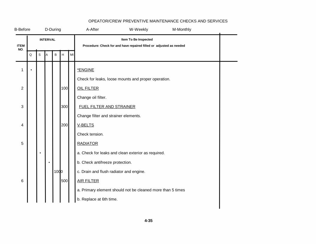
OPEATOR/CREW PREVENTIVE MAINTENANCE CHECKS AND SERVICES
B-Before D-During A-After W-Weekly M-Monthly
Q S A B H MI
1 • *ENGINE
Check for leaks, loose mounts and proper operation.
2 100 OIL FILTER
Change oil filter.
3 300 FUEL FILTER AND STRAINER
Change filter and strainer elements.
4 200 V-BELTS
Check tension.
5 RADIATOR
• a. Check for leaks and clean exterior as required.
• b. Check antifreeze protection.
1000 c. Drain and flush radiator and engine.
6 500 AIR FILTER
a. Primary element should not be cleaned more than 5 times
b. Replace at 6th time.
INTERVAL
ITEMNO.
Item To Be Inspected
Procedure: Check for and have repaired filled or adjusted as needed
4-35

ORGANIZATIONAL PREVENTIVE MA/}NTIANICE CHECKS AND SERVICESQ-Quarterly S-Semiannually A-Annually B-Biennially H-Hours MI-Miles
Q S A B H MI
7 500 FUEL TANKDrain of any water sediment
8 1000 BLOWER SCREENClean Screen.
9 100 BATTERYCheck specific gravity of electrolyte in each cell. (more frequently in warm weather).
10 50 STEERING CYLINDERSa. Check for excessive bearing play.b. Grease both fittings.
11 500 TWO SPEED TRANSMISSIONDrain, flush and fill to level plug (4 qts).
12 500 AXLE DIFFERNTIALDrain, flush and fill to level plug (4.5 qts).
13 500 BRAKE 'MASTER CYLINDERDrain, flush and fill (1pt).
14 2000 HYDRAULIC OIL SYSTEM
Drain fluid, chance filter and refill.
3-36
INTERVAL
ITEMNO.
ITEM TO BE INSPECTED
Procedure: Check for and have repaired filled or adjusted as needed

LUBRICATION CHARTAPPENDIX N
4-37

LUBRICATION CHART (Cont)
INDEX OF REFERENCE POINTS
A - Vibrator Shaft Bearing
B - Steering Cylinder Ends
C - Articulating Joints Bearings
D - Universal Joints and Slip Joint
E - Two-Speed Transmission
F - Axle Differential
J - Gear Coupling - Hydraulic Motor to Vibratory Shaft
K - Rollers Bearing
L - Hydraulic Oil System
:M - Pneumatic Isolator (25 PSI)
N - Traction Tires
S - Engine Fuel Tank
T - Engine Cooling System
U - Engine Air Cleaner
4-38

By Order of the Secretary of the Army:
E. C. MEYERGeneral, United States Army
Official: Chief of StaffJ. C. PENNINGTON
Major General, United States ArmyThe Adjutant General
Distribution:
To be distributed in accordance with DA Form 12-25B, Direct and General Support Maintenance requirements for Roller,Vibratory, Self-Propelled.
*U.S. GOVERNMENT PRINTING OFFICE: 192 - 311-831/60678


The Metric System and Equivalents
Linear Measure Liquid Measure
1 centiliter = 10 milliters = .34 fl. ounce1 centimeter = 10 millimeters = .39 inch 1 deciliter = 10 centiliters = 3.38 fl. ounces1 decimeter = 10 centimeters = 3.94 inches 1 liter = 10 deciliters = 33.81 fl. ounces1 meter = 10 decimeters = 39.37 inches 1 dekaliter = 10 liters = 2.64 gallons1 dekameter = 10 meters = 32.8 feet 1 hectoliter = 10 dekaliters = 26.42 gallons1 hectometer = 10 dekameters = 328.08 feet 1 kiloliter = 10 hectoliters = 264.18 gallons1 kilometer = 10 hectometers = 3,280.8 feet
Square MeasureWeights
1 sq. centimeter = 100 sq. millimeters = .155 sq. inch1 centigram = 10 milligrams = .15 grain 1 sq. decimeter = 100 sq. centimeters = 15.5 sq. inches1 decigram = 10 centigrams = 1.54 grains 1 sq. meter (centare) = 100 sq. decimeters = 10.76 sq. feet1 gram = 10 decigram = .035 ounce 1 sq. dekameter (are) = 100 sq. meters = 1,076.4 sq. feet1 decagram = 10 grams = .35 ounce 1 sq. hectometer (hectare) = 100 sq. dekameters = 2.47 acres1 hectogram = 10 decagrams = 3.52 ounces 1 sq. kilometer = 100 sq. hectometers = .386 sq. mile1 kilogram = 10 hectograms = 2.2 pounds1 quintal = 100 kilograms = 220.46 pounds Cubic Measure1 metric ton = 10 quintals = 1.1 short tons
1 cu. centimeter = 1000 cu. millimeters = .06 cu. inch1 cu. decimeter = 1000 cu. centimeters = 61.02 cu. inches1 cu. meter = 1000 cu. decimeters = 35.31 cu. feet
Approximate Conversion Factors
To change To Multiply by To change To Multiply by
inches centimeters 2.540 ounce-inches Newton-meters .007062feet meters .305 centimeters inches .394yards meters .914 meters feet 3.280miles kilometers 1.609 meters yards 1.094square inches square centimeters 6.451 kilometers miles .621square feet square meters .093 square centimeters square inches .155square yards square meters .836 square meters square feet 10.764square miles square kilometers 2.590 square meters square yards 1.196acres square hectometers .405 square kilometers square miles .386cubic feet cubic meters .028 square hectometers acres 2.471cubic yards cubic meters .765 cubic meters cubic feet 35.315fluid ounces milliliters 29,573 cubic meters cubic yards 1.308pints liters .473 milliliters fluid ounces .034quarts liters .946 liters pints 2.113gallons liters 3.785 liters quarts 1.057ounces grams 28.349 liters gallons .264pounds kilograms .454 grams ounces .035short tons metric tons .907 kilograms pounds 2.205pound-feet Newton-meters 1.356 metric tons short tons 1.102pound-inches Newton-meters .11296
Temperature (Exact)
°F Fahrenheit 5/9 (after Celsius °Ctemperature subtracting 32) temperature

PIN: 048309-000

This fine document...
Was brought to you by me:
Liberated Manuals -- free army and government manuals
Why do I do it? I am tired of sleazy CD-ROM sellers, who take publicly available information, slap “watermarks” and other junk on it, and sell it. Those masters of search engine manipulation make sure that their sites that sell free information, come up first in search engines. They did not create it... They did not even scan it... Why should they get your money? Why are not letting you give those free manuals to your friends?
I am setting this document FREE. This document was made by the US Government and is NOT protected by Copyright. Feel free to share, republish, sell and so on.
I am not asking you for donations, fees or handouts. If you can, please provide a link to liberatedmanuals.com, so that free manuals come up first in search engines:
<A HREF=http://www.liberatedmanuals.com/>Free Military and Government Manuals</A>
– SincerelyIgor Chudovhttp://igor.chudov.com/
– Chicago Machinery Movers