
TM 14ADV - fujitsu.com
158
TM 14ADV USER’S MANUAL 14 ppm page printer
Transcript of TM 14ADV - fujitsu.com

TM
14ADV
USER’S MANUAL
14 ppm page printer

User’s Manual FM-1
Federal Communications CommissionRadio Frequency Interference Statement
Notice: This equipment has been tested and found to comply with the limits for aClass B digital device, pursuant to Part 15 of the FCC Rules. These limits aredesigned to provide reasonable protection against harmful interference in aresidential installation. This equipment generates, uses, and can radiate radiofrequency energy and, if not installed and used in accordance with the instructions,may cause harmful interference to radio communications. However, there is noguarantee that interference will not occur in a particular installation. If thisequipment does cause harmful interference to radio or television reception, whichcan be determined by turning the equipment off and on, the user is encouraged totry to correct the interference by one or more of the following measures:
• Reorient or relocate the receiving antenna.• Increase the separation between the equipment and receiver.• Connect the equipment into an outlet on a circuit different from that to which the
receiver is connected.• Consult the dealer or an experienced radio / TV technician for help.
FCC warning: Changes or modifications not expressly approved by the partyresponsible for compliance could void the user’s authority to operate the equipment.
Notes• Testing of this equipment was performed on model number M3878SA14AV.• The use of a non-shielded interface cable with the referenced device is prohibited.
The length of the parallel interface cable must be 3␣ meters (10␣ feet) or less. Thelength of the serial interface cable must be 15␣ meters (50␣ feet) or less.
• The length of the power cord must be 3 meters (10 feet) or less.
Laser Safety Information
This printer has been designed and manufactured according to FDA regulations“title 21, CFR, chapter I, subchapter J, based on the Radiation Control for Healthand Safety Act of 1968”, and is classified as class 1 laser product.
Warning: Use of controls, adjustments or performance of procedures other thanthose specified herein may result in hazardous radiation exposure.
This class B digital apparatus meets all requirements of the Canadian Interference-Causing Equipment Regulations.
Cet appareil numérique de la Classe B respecte toutes les exigences du Règlement surle matériel brouilleur du Canada.
Bescheinigung des Herstellers/Importeurs
Hiermit wird bescheinigt, daß der M3878SA14AV der Maschinenlärminfor-mationsverordnung 3. GSGV, 18.01.1991 entspricht. Der höchste Schalldruckpegelbeträgt 70 dB (A) oder weniger gemäß EN27779-1991.
Notice to AmericanUsers
Notice to CanadianUsers
Notice to GermanUsers
01 Front Matter 07.08.1997, 11:39 Uhr1
FM-2 User’s Manual
In case that the interface board, Ethernet C, is installed, this equipment complieswith EMI regulations as follows:
Notice to AmericanUsers
Federal Communications CommissionRadio Frequency Interference Statement
Notice: This equipment has been tested and found to comply with the limits for aClass A digital device, pursuant to Part 15 of the FCC Rules. These limits aredesigned to provide reasonable protection against harmful interference when theequipment is operated in a commercial environment. This equipment generates,uses, and can radiate radio frequency energy and, if not installed and used inaccordance with the instruction manual, may cause harmful interference to radiocommunications. Operation of this equipment in a residential area is likely to causeharmful interference in which case the user will be required to correct theinterference at his own expense.
FCC warning: Changes or modifications not expressly approved by the partyresponsible for compliance could void the user’s authority to operate the equipment.
Notes• Testing of this equipment was performed on model number M3878SA14AV.• The use of a non-shielded interface cable with the referenced device is prohibited.
The length of the parallel interface cable must be 3␣ meters (10␣ feet) or less. Thelength of the Ethernet interface cable must be 100␣ meters (328␣ feet) or less for type10BASE-2 and 185 meters (607 feet) or less for type 10BASE-T.
• The length of the power cord must be 3 meters (10 feet) or less.
Laser Safety Information
This printer has been designed and manufactured according to FDA regulations“title 21, CFR, chapter I, subchapter J, based on the Radiation Control for Healthand Safety Act of 1968”, and is classified as class 1 laser product.
Warning: Use of controls, adjustments or performance of procedures other thanthose specified herein may result in hazardous radiation exposure.
This class A digital apparatus meets all requirements of the Canadian Interference-Causing Equipment Regulations.
Cet appareil numérique de la Classe A respecte toutes les exigences du Règlement surle matériel brouilleur du Canada.
Bescheinigung des Herstellers/ImporteursHiermit wird bescheinigt, daß der M3878SA14AV der Maschinenlärminformations-verordnung 3. GSGV, 18.01.1991 entspricht: Der höchste Schalldruckpegel beträgt70 dB (A) oder weniger gemäß EN27779-1991.
Warning: This is a product which meets Class A of EN55022 and AS/NZS3548.In a domestic environment this product may cause radio interference in which casethe user may be required to take adequate measures.
Notice to GermanUsers
Notice to Europeanand Oceanian Users
Notice to CanadianUsers
01 Front Matter 07.08.1997, 11:39 Uhr2

User’s Manual FM-3
As an International ENERGY STARSM Partner, Fujitsu Limited has determined thatthis product meets the International ENERGY STAR Office Equipment Program forenergy efficiency.
The International ENERGY STAR Office Equipment Program is an internationalprogram that promotes energy saving through the use of computers and other officeequipments. The program backs the development and dissemination of productswith functions that effectively reduce energy consumption. It is an open system inwhich business proprietors can participate voluntarily. The targeted products areoffice equipment such as computers, displays, printers, facsimiles, and copiers.Their standards and logos are uniform among participating nations.
This product sold in Europe conforms to the standards in accordance with ECDirectives. The copy of “Declaration of Conformity” is attached in the next page.
CE Declaration
01 Front Matter 07.08.1997, 11:39 Uhr3

FM-4 User’s Manual
01 Front Matter 07.08.1997, 11:39 Uhr4

User’s Manual FM-5
The contents of this manual may be revised without prior notice andwithout obligation to incorporate changes and improvements into unitsalready shipped.
Fujitsu has made every effort to ensure that the information includedhere is complete and accurate at the time of publication. The companyassumes no liability for errors and omissions.
Copyright © 1997 Fujitsu Limited
Printed in Japan. All rights reserved. No part of this manual may bereproduced or translated, stored in a database or retrieval system, ortransmitted, in any form or by any means, electronic, mechanical,photocopying, recording, or otherwise, without the prior writtenpermission of Fujitsu Limited.
C145-E172-01EN, January 1997
Trademark AcknowledgmentFujitsu is a registered trademark of FujitsuLimited. The following companies ownthe other trademarks used in this manual:Adobe Systems, Inc.: PostScriptAgfa Division of Miles Inc.: Albertus,Antique Olive, Arial, CG Omega, CGTimes, Clarendon Condensed, Coronet,Courier, Garamond, Letter Gothic,Marigold, Symbol, Times New Roman,Univers, Univers Condensed, WingdingsApple Computer, Inc.: AppleTalk,LocalTalk, Macintosh, TrueTypeAT&T: UNIX
Centronics Data Computer Corporation:CentronicsHewlett-Packard Corporation: Hewlett-Packard, LaserJet, LaserJet 4, PCLInternational Business MachinesCorporation: IBM, IBM PC/AT, IBMPS/2, PC-DOSMicrosoft Corporation: Microsoft, MS-DOS, WindowsLexmark: MarkVisionMiles, Inc.: IntellifontNovell, Inc.: NetwareXerox Corporation: 4024, Ethernet,Xerox
01 Front Matter 07.08.1997, 11:39 Uhr5

FM-6 User’s Manual
Precautions
Read this section and remember these instructions to ensure your safety andyour printer’s correct performance. Follow the cautions and notices labeled onthe printer or marked with icons in the manual. Save this manual for futurereference.• Use only the power cord furnished with the printer and a properly grounded
outlet. Do not use an extension power cord.• Confirm that the rated voltage of your printer matches the voltage of your
power outlet. The maximum wattage of the printer is 600 watts.• Turn off the printer and disconnect the power cord before beginning
maintenance operations.• Disconnect the power cord from the outlet whenever you are not using the
printer for an extended period of time.• Disconnect the power cord from the outlet whenever thunder storms are
nearby. Leaving the power cord connected may allow damage to the printeror other property.
• Do not put the printer in direct sunlight, near a heater, or near water. Leaveadequate space around the printer.
• Do not touch any connector contacts and corona wires. This could causeelectrostatic damage to the printer.
• Do not touch the heat roller and motors if you have been printing recently.These parts may be hot.
• Do not touch or scratch the green drum surface, and do not expose it to lightfor more than three minutes.
• Use only a shielded interface cable of 3 meters (10 feet) or less for the parallelinterface, 15 meters (50 feet) or less for the serial interface, 100 meters (328feet) or less for Ethernet interface 10BASE-T connection, and 185 meters(607 feet) or less for the Ethernet interface 10BASE-2 connection.
• Be sure the printer is turned off before connecting the interface.• Do not turn the printer off while it is printing.• Do not disassemble or remove any components unless instructed in the
maintenance procedures.• Keep the print unit upright when removing or installing it.• Do not apply excessive pressure on the corona wire when cleaning it.• Do not use alcohol or other cleaning solutions on the drum surface or on any
interior parts of the printer.• Clear paper jams quickly, especially when they occur in the heat roller unit.• Do not drop small objects, such as paper clips, into the printer.• Do not set page margins off the physically printable page area.• Turn off the printer and disconnect the power cord immediately if an
abnormal condition occurs: for instance, if the printer smokes, printsabnormally, becomes wet, or falls. Then consult your dealer.
01 Front Matter 07.08.1997, 11:39 Uhr6

User’s Manual i
Contents
Preface ............................................................................................ vManual and Floppy Disks ................................................................. vOperating Environments ................................................................. viConventions .................................................................................... vi
Control Panel ........................................................................... vii
Chapter 1 Getting Started ........................................................................... 1–1Getting Acquainted ..................................................................... 1–1Getting Ready ............................................................................. 1–4
Picking a Suitable Location ................................................... 1–4Unpacking and Checking Your Printer ................................. 1–5
Setting Up ................................................................................... 1–7Preparing the Print Unit and Installing the Toner Bottle ...... 1–7Installing the Cleaner and Cleaner Pad ............................... 1–10Loading Paper and Installing the Paper Tray ....................... 1–12Installing the Multi-function Feeder ................................... 1–15Connecting the Power Cord ............................................... 1–16
Connecting the Printer to Your Computer ................................ 1–17About Interfacing ................................................................ 1–17Connecting to the Parallel Port ........................................... 1–18Printing a Test Page Offline ................................................ 1–19
Selecting an Emulation .............................................................. 1–20Installing the Printer Driver ....................................................... 1–21
Get to Know Your Printer Driver ....................................... 1–21Standard Printer Driver for Windows 3.1/3.11 ................... 1–22FPS Printer Driver for Windows 3.1/3.11........................... 1–22Standard Printer Driver for Windows 95 ............................ 1–22
Plug and Play Printer Detection ................................... 1–23Set-up from "Printers" Folder ....................................... 1–23
FPS Printer Driver for Windows 95 .................................... 1–24Printing Your First Document ................................................... 1–26
Adjusting Print Density ...................................................... 1–27If Something Goes Wrong .................................................. 1–28
Where To Go From Here .......................................................... 1–29
02 Contents 07.08.1997, 11:39 Uhr1

ii User’s Manual
Chapter 2 Using Printer Software ............................................................... 2–1Remote Setup Utility Program, PPMENU .................................. 2–1
Installing PPMENU ............................................................. 2–2Factory Defaults .................................................................... 2–4
Printer Management Utility Program, Lexmark’s MarkVision ..... 2–6Installing MarkVision ........................................................... 2–6Menu Bar Functions ............................................................. 2–7
Chapter 3 Printing and Paper Handling ...................................................... 3–1Control Panel Tutorial ................................................................ 3–1
The Control Panel ................................................................ 3–1Indicators ....................................................................... 3–2Message Display ............................................................. 3–3Buttons........................................................................... 3–3
Control Panel Functions .............................................................. 3–5Changing Message Language................................................. 3–5Printing Data Remaining in the Buffer ................................. 3–5Clearing an Error Condition to Continue Printing ............... 3–5Clearing the Buffer and Reinitializing the Printer .................. 3–6Printing a Status Report ........................................................ 3–6Printing a Font Report .......................................................... 3–8Selecting Paper Tray, MFF, or Manual Paper Feed ............. 3–10Setting MFF Paper Size ....................................................... 3–11Selecting Menu Option and Resetting Menu ...................... 3–12
Menu Functions ........................................................................ 3–12Menu Structure and How to Use Control Panel Buttons .... 3–12Submenus, Items, and Options ........................................... 3–13
Menu Items ............................................................................... 3–16Handling Paper ......................................................................... 3–20
Paper Types and Sizes ......................................................... 3–20General Tips ................................................................. 3–22Preprinted Sheets .......................................................... 3–23Transparencies .............................................................. 3–23Envelopes ..................................................................... 3–24Labels ........................................................................... 3–25
Changing the Paper Tray Size ............................................. 3–25Using the Multi-function Feeder ......................................... 3–27Feeding Paper Manually ...................................................... 3–29Setting Up the Rear Stacker ................................................ 3–30Printing on Nonstandard Size Paper and on Envelopes ....... 3–31
Considerations on Paper Size ........................................ 3–31Page Orientation .......................................................... 3–32
Contents
02 Contents 07.08.1997, 11:39 Uhr2

User’s Manual iii
Chapter 4 Enhancing and Customizing the Printer ..................................... 4–1Adding RAM ............................................................................... 4–1Installing an Interface Expansion Board ....................................... 4–4
Installing an Interface Board ................................................. 4–4Connecting to the Serial Port ................................................ 4–5
Connecting the Serial Interface Cable ............................. 4–5Selecting the Serial Interface ........................................... 4–6Verifying Serial Parameter Settings ................................. 4–6
Connecting to the LocalTalk Port ......................................... 4–7Connecting the LocalTalk Interface Cable ...................... 4–8Selecting the LocalTalk Interface .................................... 4–8LocalTalk Specifications ................................................. 4–8
Connecting to the Ethernet Port ........................................... 4–9Connecting the Ethernet Interface Cable ........................ 4–9Selecting the Ethernet Interface .................................... 4–10Ethernet Specifications ................................................. 4–10
Adding Paper Sources ................................................................ 4–10Paper Feeder ....................................................................... 4–10Changing the Paper Tray Size ............................................. 4–12Different Paper Tray Sizes ................................................... 4–15
Adding Duplex Unit .................................................................. 4–15
Chapter 5 Maintenance .............................................................................. 5–1Preventive Maintenance ............................................................... 5–1Periodic Routine Maintenance .................................................... 5–2
Replacing the Toner Bottle and Cleaner Pad ......................... 5–2Replacing the Print Unit and Internal Cleaning .................... 5–7
Removing the Print Unit ................................................ 5–8Cleaning the Paper Path ............................................... 5–10Cleaning the Corona Wire ........................................... 5–10Cleaning the Paper Guide before the Corona Wire....... 5–11Installing the New Print Unit ....................................... 5–12Resetting the Print Unit Counter ................................. 5–15
Cleaning the Precharger Wire ............................................. 5–17Repacking the Printer ................................................................ 5–18
Contents
02 Contents 07.08.1997, 11:39 Uhr3

iv User’s Manual
Contents
Chapter 6 Solving Problems ....................................................................... 6–1Clearing Paper Jams .................................................................... 6–1Operational Problems ................................................................ 6–10Print Quality Problems .............................................................. 6–11Error Indications ....................................................................... 6–13Action-required Status Indications ............................................. 6–16Printer Status Indications .......................................................... 6–17Warning Messages ..................................................................... 6–18
Appendix A Font Samples .............................................................................. A–1PCL Mode .................................................................................. A–1FPS Mode ................................................................................... A–2
Appendix B Supplies and Accessories .......................................................... B–1Supplies ....................................................................................... B–1Accessories ................................................................................... B–1
Appendix C Specifications ............................................................................C–1
Glossary ................................................................................... GL–1
Index ......................................................................................... IN–1
Fujitsu Offices ......................................................... Inside back cover
02 Contents 07.08.1997, 11:39 Uhr4

User’s Manual v
Preface
Thank you for purchasing the Fujitsu PrintPartner 14ADV Page Printer.The PrintPartner 14ADV is a 14-ppm, 600-dpi, laser printer. It iscompatible with the HP LaserJet 4 printers or PostScript level 2 printerswhich are main printers of the industry-standard page printers.
Available options are:
• 1-, 2-, 4-, 8-, 16-, and 32-megabyte memory expansion cards
• Interface expansion boards: serial interface, LocalTalk, and Ethernet C
• Paper trays (trays 1 and 2): A4, A5, letter, legal, and executive sizes
• Paper feeder: Base mechanism plus paper tray (tray 2)
• Duplex unit: Two-sided printing mechanism
The PrintPartner 14ADV has a single user’s manual. This user’s manualprovides a summary of everything for from non-technical users unfamiliarwith page printers to highly experienced technical users.
The PrintPartner 14ADV comes with seven floppy disks.• Windows Printer Drivers (two disks) which provide the computer’s
operating system with the programs that control this printer.• MarkVision (three disks), printer management utility program,
which allows you to easily understand the printer (status, statistics,or features) and displays the printer control panel on yourcomputer display to remotely operate the printer.
• Network Printer Utility (one disk), which allows you to remotelychange or confirm settings of Ethernet C board of the printer orlocally check the printer.
• PPMENU (one disk), the printer remote setup utility program,which allows you to easily customize and program your printer toyour computer and software environments, using your computerkeyboard and display.
Manual andFloppy Disks
03 Preface 07.08.1997, 11:39 Uhr5

vi User’s Manual
To run the Printer Driver, you need an IBM PC/AT or PS/2computer or compatible running MS-Windows 3.1/3.11 or MS-Windows 95.
To run MarkVision, you need an IBM PC/AT or PS/2 computer orcompatible running MS-Windows 95 (not MS-Windows 3.1/3.11),with at least 5MB of memory available on a hard disk, a 3.5" double-sided high density (2HD) floppy disk drive, and a VGA (640 × 480dots) or higher resolution display.
To run the Network Printer Utility, you need an IBM PC/AT or PS/2 computer or compatible running MS-Windows 3.1/3.11 (not MS-Windows 95), with at least 5MB of memory available on a hard disk,a 3.5" double-sided high density (2HD) floppy disk drive, and aVGA (640 × 480 dots) or higher resolution display.
To run PPMENU, you need an IBM PC/AT or PS/2 computer orcompatible running MS-DOS, with at least 1MB of memoryavailable on a hard disk, a 3.5" double-sided high density (2HD)floppy disk drive, and a VGA (640 × 480 dots) display. You mustalso be using PC-DOS version 5.02, MS-DOS version 3.3, or higherversion.
Icons draw your attention to advisory messages, as illustrated below.A line precedes and follows the message to show where the messagebegins and ends.
Caution:Ignoring this information could result in personal injury.
Notice:Ignoring this information could result in loss of data or harm to yourequipment.
Important:These notes contain remarks, tips, and other useful supplementaryinformation.
Operating Environments
OperatingEnvironments
!
☞
✍
Conventions
03 Preface 07.08.1997, 11:39 Uhr6

User’s Manual v i i
Control Panel
The printer’s control panel incorporates two rows of buttons, with eachbutton having one or two labels (see below). The physical button isbeneath the rectangular section of no-labeled space. The top labelrepresents the basic function, which is activated by a touch of thebutton. The bottom label represents the second function, which isactivated when you release the button after holding it down more thanfive seconds.
MFFPAPER SIZE
PRINTFONT
SELFTEST
RESET
CONT. ENTER –
+MENUREADYFORMFEED
RESETMENU
TRAYSELECT Basic functions
Second functions
Physical buttons
Basic functions
Second functions
Physical buttons
The control panel has a character display of 16 columns × 2 lines.
In text, the names of the control panel buttons appear as all capitalletters inside a box like and control panel display messagesappear in a fixed-spacing font like READY. Button names or messagesoccupying two lines are expressed in a single line shown below.
Buttons:
Display messages:
FORM FEED
READY TONER LOWREADYTONER LOW
The asterisk in the display column indicates that the displayedoption is currently selected in the selected menu.
FORMFEED
Operating Environments
03 Preface 07.08.1997, 11:39 Uhr7

viii User’s Manual
Changing Message Language ( )
You can select a language used for control panel messages. Selectablelanguages are English, French, German, Italian, Spanish, and Swedish.
To select a language, follow these steps:
1. Turning the printer on while pressing .
The message C.P.LANGUAGE ENGLISH appears after printerinitialization.
2. Press the or button until the desired language appears. Pressthe button.
The asterisk appears after the language, indicating the language isselected.
3. Save the selection.
Pressing the button saves the new setting and returns theprinter to the ready state. The printer will display the selectedlanguage for messages.
Operating Environments
03 Preface 07.08.1997, 11:39 Uhr8

User’s Manual 1-1
GETTINGSTARTED1
CHAPTER
Getting Started
This chapter provides complete setup instructions in the followingsections:
•Getting Acquainted. Learning the printer’s main parts and its paperpaths.
•Getting Ready. Choosing a suitable location and unpacking the printer.
•Setting Up. Assembling the printer.
•Connecting the Printer. Selecting an interface and connecting to thecomputer.
•Installing the Printer Driver.
•Printing Your First Document.
•Where to Go from Here.
The illustrations on the following pages identify the main parts of theprinter and two routes of paper feeding. These parts are referred tothroughout the manual, so take some time to become familiar withthem.
GettingAcquainted
04 Chapter 1 07.08.1997, 11:39 Uhr1

1-2 User’s Manual
Figure 1–1 Front and right side view
Figure 1–2 Rear and left side view
Getting Acquainted
Control panel
Slide cover(Font/emulation card slotand RAM card slots inside)
Multi-functionfeeder cable
Paper tray
Front cover(opened)
Upper door
Top cover(Paper stacker)
Stacker-full sensor
Multi-function feeder(MFF)
Paper guides formanual feeding
Paper guides forstack feeding
Rear stacker
Power switch
Power cordconnector
Centronics parallelinterface connector
Interface boardslot cover
04 Chapter 1 07.08.1997, 11:39 Uhr2

User’s Manual 1-3
GETTINGSTARTED
Getting Acquainted
From optional paper tray
Figure 1–3 Interior view
The path from the paper tray to the top cover is for ordinary paper.The straight path from the manual feed slot or optional multi-function feeder to the rear stacker is for transparencies and envelopes.
Figure 1–4 Paper paths
Toner bottle
Print density dial
Print unit
Paper tray
Top cover(main stacker)
Rearstacker
Manualfeedslot
04 Chapter 1 07.08.1997, 11:39 Uhr3
1-4 User’s Manual
Getting Ready
Getting Ready
below+10°C
above+35°C
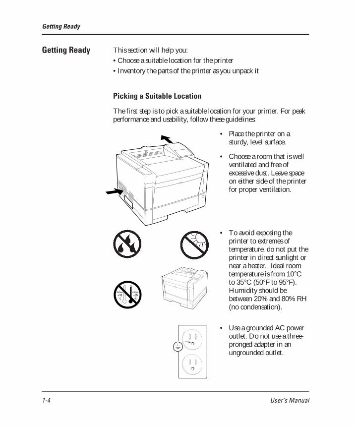
This section will help you:
• Choose a suitable location for the printer
• Inventory the parts of the printer as you unpack it
Picking a Suitable Location
The first step is to pick a suitable location for your printer. For peakperformance and usability, follow these guidelines:
• Place the printer on asturdy, level surface.
• Choose a room that is wellventilated and free ofexcessive dust. Leave spaceon either side of the printerfor proper ventilation.
• To avoid exposing theprinter to extremes oftemperature, do not put theprinter in direct sunlight ornear a heater. Ideal roomtemperature is from 10°Cto 35°C (50°F to 95°F).Humidity should bebetween 20% and 80% RH(no condensation).
• Use a grounded AC poweroutlet. Do not use a three-pronged adapter in anungrounded outlet.
04 Chapter 1 07.08.1997, 11:39 Uhr4

User’s Manual 1-5
GETTINGSTARTED
• Use only the power cordfurnished with the printer.Do not use an extensioncord.
• Do not touch anyconnector contacts andcorona wires to avoidpossible electrostaticdamage to the printer.
• Do not use a circuit sharedwith equipment that causeselectrical noise, such asmotors.
• Do not use a circuit sharedwith equipment that uses alot of power, such as acopier or a coffee maker.
Unpacking and Checking Your Printer
As you unpack the printer, check each item carefully for damage. Ifyou find damage, notify your dealer. Check also that you havereceived all the items shown below.
This printer comes with everything you need except an interfacecable. If you do not yet have a cable, you must purchase one beforeyou can connect the printer to your computer.
Important:Save the original carton and packing materials in case you need tostore or transport your printer.
Getting Ready
✍
04 Chapter 1 07.08.1997, 11:39 Uhr5

1-6 User’s Manual
• An interface cable is not a standard accessory. Please purchasean appropriate cable according to the interface you intend touse.
• The power cord may differ slightly from this figure dependingon the country where you purchased the printer.
• The multi-function feeder (MFF) is separately packaged.
Figure 1-5 Printer inventory
Print unit(placed in printer)
Printer
Getting Ready
Tonerbottle
Printer driverdisks
MarkVision disks
Network printerutility disk PPMENU disk
Multi-functionfeeder (MFF)
Paper sizelabel
User’smanual
Cleaningbrush
Cleaner andcleaner pad
Powercord
04 Chapter 1 07.08.1997, 11:39 Uhr6

User’s Manual 1-7
GETTINGSTARTED
This section describes how to assemble the printer and connect thepower cord after choosing a suitable location for the printer andchecking that you received all the parts.
Preparing the Print Unit and Installing the Toner Bottle
This printer is shipped with the print unit mounted and protectivematerials attached. Be sure to remove the two protective materialsfrom the print unit. This operation is possible with the print unitmounted. First prepare and install the following two components:
• Print unit (photoconductor drum, developing unit, etc.)
• Toner bottle
The toner bottle first installed after you purchase the printer will lastabout 2500 printed pages under the condition of 5% coverage on A4paper. The succeeding toner bottles last about 5000 printed pageseach.
Notice:Do not touch any connector contacts and corona wires to avoidpossible electrostatic damage to the printer.
Be careful with the print unit’s drum (the green surface). The drumis easily damaged by contamination or by exposure to light for morethan three minutes. Follow these guidelines:
• Never touch or scratch the drum surface.
• When the print unit is not in the printer, store it in a dark place orcover it with a clean sheet of paper.
• When the print unit is in the printer, keep the printer top coverclosed. If you must work inside the printer for more than threeminutes, remove the print unit with the toner bottle mounted andstore it in a dark place.
Setting Up
Setting Up
☞
04 Chapter 1 07.08.1997, 11:39 Uhr7

1-8 User’s Manual
To prepare the print unit and install the toner bottle, follow these steps:
1. Open the upper door. Liftthe milled portions at thefront left and right of theupper door to open it.
2. Remove the protectivematerials from the printunit. Remove protective sheetq. Pull clear tape w until itsblue end is visible and removeit. Remove two restraintcushions e.
3. Remove the toner bottlefrom its bag.
4. Shake the toner bottle bymoving it back and forth ina horizontal motion severaltimes.
5. Remove the plastic sealfrom the toner bottle.Gently pull off the seal beingcareful not to spill toner.Handle to seal carefully toavoid staining your hands orclothes.
Setting Up
Projecting guide
qw
e
04 Chapter 1 07.08.1997, 11:39 Uhr8
User’s Manual 1-9
GETTINGSTARTED
Setting Up
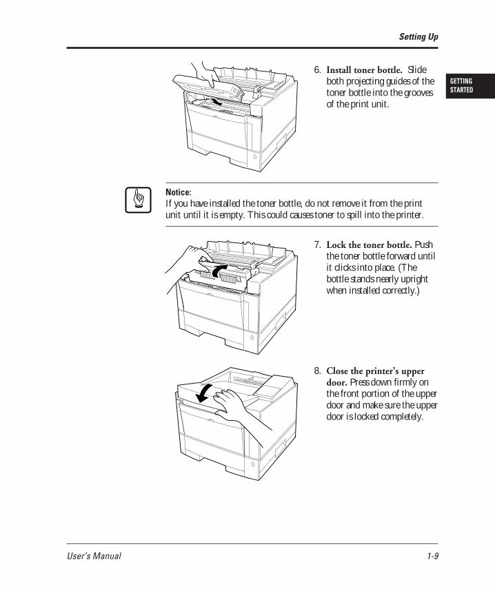
6. Install toner bottle. Slideboth projecting guides of thetoner bottle into the groovesof the print unit.
Notice:If you have installed the toner bottle, do not remove it from the printunit until it is empty. This could causes toner to spill into the printer.
7. Lock the toner bottle. Pushthe toner bottle forward untilit clicks into place. (Thebottle stands nearly uprightwhen installed correctly.)
8. Close the printer’s upperdoor. Press down firmly onthe front portion of the upperdoor and make sure the upperdoor is locked completely.
☞
04 Chapter 1 07.08.1997, 11:39 Uhr9

1-10 User’s Manual
Setting Up
Installing the Cleaner and Cleaner Pad
This printer is shipped without installing the cleaner and cleaner padwhich removes dirt from the pressure roller in the fuser unit. Be sureinstall the cleaner and cleaner pad before printing.
To install the cleaner and cleaner pad, follow these steps:
1. Mount the cleaner pad onthe cleaner. Put the cleanerpad on the cleaner and slidethe cleaner pad into thelocked position.
2. Open the cover. Push theengraved portion on thestacker to unlock the cover.
04 Chapter 1 07.08.1997, 11:39 Uhr10

User’s Manual 1-11
GETTINGSTARTED
Setting Up
3. Lift the front of the coverto open the cover.
4. Install the cleaner in theprinter. Grasp the handleof the cleaner and put theleft end of the cleaner intothe opening, and then theright end.
5. Lock the cleaner. Pushdown the top of the handleand pull it towards you tolock the cleaner.
6. Close the cover.
04 Chapter 1 07.08.1997, 11:39 Uhr11

1-12 User’s Manual
Setting Up
Loading Paper and Installing the Paper Tray
This printer has a single paper tray that is preset for letter size (8.5 x 11.0inches) paper for U.S. customers and to A4 size (210 x 297 mm) paperfor European customers. (You can adjust the paper tray to a different sizepaper. See Chapter 3. You can purchase an optional paper tray. SeeChapter 4 and Appendix B.) You should load about 50 sheets of copierpaper to test the printer.
1. Pull the paper tray out ofthe printer.
2. Prepare the paper tray.Remove restraint card boardq and tapes securing the rearpaper guide. Check greenindicator w is positionedaccording to the tray sizelabel (*).
3. Lock the pressure plate. Ifthe front of the pressure plateis raised, push it down untilthe pressure plate clicks intoplace.
4. Widen the side guides.While bending both sideguides inward q, push theirinner PUSH marks outwardw.
q
*w
04 Chapter 1 07.08.1997, 11:39 Uhr12

User’s Manual 1-13
GETTINGSTARTED
5. Prepare a paper stack.Prepare paper of the sizeindicated by the size label (*).Fan the paper stack both waysto prevent sheets fromsticking together.
Notice:Put the paper stack in the paper tray with the printing side faced down.
If paper is curled, remove the curl.
6. Load the paper. Place thefront portion of the paperstack on the tray and slide itbackwards so that the stack isplaced under the twostoppers. Gather the edges ofthe stack together to ensurecorrect positioning of paperin the tray.
Make sure the stack does notexceed the limit mark.
7. Adjust the side guides. Pushthe outer PUSH mark ofeither side guide to the widthof paper. Align the rear edgesof the paper stack.
Setting Up
☞
Limit mark
Bad placement
Good placement
04 Chapter 1 07.08.1997, 11:39 Uhr13

1-14 User’s Manual
Setting Up
Guide
8. Arrange paper edges. Rockthe paper tray to gather theedges of the stack together toensure correct positioning ofpaper in the tray.
9. Install the paper tray. Alignthe sides of the tray with theguide grooves of the tray slot(the left groove is engravedwith a arrow) and firmly slidethe tray all the way into theslot.
Notice:You cannot install the paper tray with the pressure plate raised.
10.Remove the protectivematerial from the rearstacker. Open the rear stackerand remove restraint cushionq. Make sure the paperguide is pushed down in thelocked position. Close therear stacker.
Notice:If the paper guide is not in the locked position, the printer will not work.
☞
q
☞
04 Chapter 1 07.08.1997, 11:39 Uhr14

User’s Manual 1-15
GETTINGSTARTED
Installing the Multi-function Feeder
The multi-function feeder (MFF) is useful to print a lot of envelopesor transparencies. The MFF can hold and deliver 100 sheets of 0.09mm thick paper or 30 envelopes. Note that the printer works if theMFF is not installed.
Paper guidesfor manual feed
MFF connector
Hook
Paper guidesfor paper stack
Lever
Notice:When using paper, do not leave the paper in the multi-functionfeeder for long time. It may cause waving of paper and dropouts inprinting.
Because the MFF does not have a mechanism that detects thephysical size of paper in use, you must inform the printer of thepaper size. Use the MFF paper size menu to select a paper size whichequals the size of paper loaded in the MFF.
To install the multi-function feeder, follow these steps:
Notice:Be sure that the printer is turned off before installing or removingthe multi-function feeder.
1. Open the front cover.
☞☞
Setting Up
04 Chapter 1 07.08.1997, 11:39 Uhr15

1-16 User’s Manual
2. Fasten the feeder to theprinter. Insert the left andright supports and hooks ofthe multi-function feederinto the correspondingopenings at the front of theprinter so that the hookscatch the pins firmly.
3. Connect the feeder cable.Connect the feeder cable tothe connector at the rightside of the printer. Orientthe arrow mark of thecable’s connector right.
Notice:To avoid paper jams or other feeding errors, make sure that each ofthe left and right hooks securely hangs on the pin.
Connecting the Power Cord
This printer comes equipped with one of the two voltage ratings:
• 120 VAC (such as for the USA)
• 220 to 240 VAC (such as for Europe)
The manufacturer’s nameplate on the back of the printer indicates thisrating. Confirm that the rated voltage of your printer matches the voltageof your power outlet.
1. Check that the printer isturned off. The “O”-markedside of the switch should bedepressed.
2. Plug the female end of thepower cord into theconnector on the left backof the printer.
Setting Up
Arrowmark
☞
04 Chapter 1 07.08.1997, 11:39 Uhr16

User’s Manual 1-17
GETTINGSTARTED
3. Plug the male end into awall outlet.
Caution:For your safety, use only a properly grounded outlet. To avoid possibleelectromagnetic interference or power supply problems, do not use anextension cord.
This section explains how to connect the printer to your computer viathe parallel interface. For information about the serial interface (option),see Chapter 4.
Notice:The following restrictions apply to interface cables:
• To comply with regulations for radio frequency emissions, use onlyshielded cable for computer-to-printer communications.
• The length of the parallel interface cable must be 3 meters (10 feet) orless.
About Interfacing
You can connect the printer to your computer using a standard parallelinterface. Many computers have a parallel interface port. However, ifyour computer does not have the parallel interface port, or for printersused in a network, the following optional interfaces are available.
Connecting the Printer to Your Computer
!
☞
Connecting thePrinter to YourComputer
04 Chapter 1 07.08.1997, 11:39 Uhr17

1-18 User’s Manual
Connecting the Printer to Your Computer
• Serial (RS-232C/422A)Use a serial interface if the printer is not near the computer. Manycomputers have both parallel and serial interface ports. Serialcommunication can operate up to 15 meters (50 feet). Parallelcommunication is normally limited to 3 meters (10 feet).
• LocalTalkUse the LocalTalk interface if the printer is connected to a Macintoshnetwork.
• Ethernet CUse Ethernet C if the printer is used in a NetWare or UNIXenvironment.
For any of these options refer to Chapter 3.
Connecting to the Parallel Port
This printer does not come with a parallel interface cable. You can use astandard Centronics interface cable (sold separately) for this purpose.Your dealer can advise you on the cable you require.
Notice:Be sure the printer is turned off before connecting the interface.
Do not touch any connector contacts or corona wires to avoid possibleelectrostatic damage to the printer.
To make the connection, plugthe cable connector into theparallel interface port on theback of the printer. Secure theconnector with the wire clips.Plug the other connector intoyour computer’s parallel port.Consult your computerdocumentation if you needhelp.
☞
04 Chapter 1 07.08.1997, 11:39 Uhr18

User’s Manual 1-19
GETTINGSTARTED
POWER ONLINE DATA ERROR
MFFPAPER SIZE
PRINTFONT
SELFTEST
RESET
CONT. ENTER –
+MENUREADYFORMFEED
RESETMENU
TRAYSELECT
Connecting the Printer to Your Computer
Printing a Test Page Offline
The printer has a status report function which prints a pagesummarizing printer option settings and showing samples of residentfonts. Use this function to check the printer performance offline.
1. Turn the printer on. Theprinter initializes themechanism and then entersthe ready state. The messagedisplay indicates<<<INITIALIZE>>>,WARMING UP, then READY.
2. Print a test page offline.Press the button toput the printer offline (theONLINE indicator turnsoff). Press the button for more than fiveseconds. The messagedisplay indicates SELFTEST and the DATAindicator flashes. A statusreport page is printed.Check that the printing issuccessful.
Notice:The status report is for either the PCL emulation or the FPS emulationdepending on the emulation you used for printing the last document;however, the status report is for the FPS emulation if it is printedimmediately after the printer is turned on. To clearly select the report,use the test menu in setup mode.
READY
☞
04 Chapter 1 07.08.1997, 11:39 Uhr19

1-20 User’s Manual
POWER ONLINE DATA ERROR
POWER ONLINE DATA ERROR
MFFPAPER SIZE
PRINTFONT
SELFTEST
RESET
CONT. ENTER –
+MENUREADYFORMFEED
RESETMENU
TRAYSELECT
Selecting an Emulation
Selecting anEmulation
This printer has two emulations (PCL and FPS) as a standardfeature. You can use these emulations to connect your printer todifferent computers. PCL emulates HP LaserJet 4 printers and FPSemulates PostScript Level 2 compatible printers.
With default settings, the printer automatically selects the activeemulation. To specify an emulation, select the emulation using thecontrol panel. Use the Personality menu of the Config menu asshown below.
1. Enter setup mode. Pressthe button to putthe printer offline (theONLINE indicator turnsoff). Then, press the button briefly six times.
The message displayindicates SETUP MENUCONFIG MENU.
2. Select the Personalitymenu. Press the button briefly. The messagedisplay indicatesPERSONALITY AUTO*.
3. Select emulation. Press the button briefly. The
option AUTO changes toPCL, PS, then back toAUTO. Press the button when the desiredoption is displayed.
The selected emulation is selected (an asterisk is followed). Once youchange the emulation, the other menus automatically change toreflect the options and functions of the new emulation. For details ofthe setup menu, see Chapter 3.
PERSONALITY AUTO*
READY
POWER ONLINE DATA ERROR
SETUP MENUCONFIG MENU
04 Chapter 1 07.08.1997, 11:39 Uhr20

User’s Manual 1-21
GETTINGSTARTED
Now that you connected your printer to the parallel port of thecomputer, you are ready to install the Windows Printer Driver whichcontrols the printer. There are two printer driver disks which containStandard Driver for Windows 3.1/3.11, Standard Driver forWindows 95, and FPS Driver for Windows 95. Note that theinstallation procedure differs.
When you are using Windows 95, it is recommended that youshould install the printer driver using MarkVision because theprinter driver is reinforced with MarkVision’s features such asremotely changing settings of a network printer and checking statusof a network printer. For MarkVision, see Chapter 2.
To install a printer driver in Windows 95, note the following:
• When you install the printer driver, the original OS (CD-ROM orfloppy disks) is required during installation.
• When MarkVision may be already installed, select a printer namefollowed by (MV) in the Printers window. When MarkVision isnot installed, select a printer name not followed by (MV).
Get to Know Your Printer Driver
The Printer Driver has two functions:
1. it automatically translates formatting choices, such as tab settings orboldface type, into commands the printer understands.
2. it allows you to set up the printer according to your needs (printersettings).
If you encounter problems with this installation, confirm that yourconfiguration corresponds to the minimum requirements listed on pagevi at the start of this manual. If the configuration corresponds to theserequirements and troubles persist, contact your dealer for assistance.
When running application programs under Windows, you select theprinter type in the application program itself before you print adocument.
Installing the Printer Driver
Installing thePrinter Driver
04 Chapter 1 07.08.1997, 11:39 Uhr21

1-22 User’s Manual
Notice:If you encounter conflicts with other already installed external driversthat use bidirectional communication on the Centronics port or withdrivers of other dedicated Windows printers used in parallel with thisprinter (conflicts like the failure to establish communication between thePrinter Driver and the printer), remove these from Windows andreinstall the PrintPartner 14ADV Printer Driver.
Standard Printer Driver for Windows 3.1/3.11
To install the Windows 3.1/3.11 Printer Standard Driver, follow thesesteps:
1. Start Windows.
2. Insert the PrintPartner 14ADV Printer Driver disk into the 3.5 inchfloppy disk drive of your computer.
3. From the Windows Program Manager, select the "File" menu andchoose the "Run" command.
4. Type “A:\inst_xxx” or “B:\inst_xxx” and press the "Enter" key.
FPS Printer Driver for Windows 3.1/3.11
This printer driver is not contained in the attached floppy disks. Select aprinter driver corresponding to LaserWriter II NTX.
Standard Printer Driver for Windows 95
The Windows printer driver can be installed by either of the followingtwo methods. The first one applies when Windows 95 is started with theprinter ready and the second one applies when the printer is on afterWindows 95 has been started.
Installing the Printer Driver
☞
04 Chapter 1 07.08.1997, 11:39 Uhr22

User’s Manual 1-23
GETTINGSTARTED
Plug and Play Printer Detection
1. Windows 95 automatically detects the printer at installation time orduring the boot process.
2. Plug and Play detection code will prompt the user for the appropriatefiles, if they are not already resident in the Windows directory, bydisplaying the “New Hardware Found” dialog box.
3. From the “New Hardware Found” dialog box, select “Driver fromdisk provided by hardware manufacturer” and click “OK”.
4. The “Install from disk” dialog box will be displayed and you will beprompted to select the drive and directory containing the installationdisk.
5. Insert the Printer driver installation disk into the A: or B: drive. Type“A:\” or “B:\” and click “OK”.
6. The “Select Device” dialog box appears displaying the model-name“Fujitsu PrintPartner 14ADV”. Click “OK” to continue.
7. Follow steps 8 to 11.
Set-up from "Printers" Folder
1. Click the "Start" button, point to "Settings", and then click "Printers".
2. Double-click "Add Printer".
3. The "Add Printer Wizard" will appear. Click “Next>”.
4. Click “Have Disk” from the next dialog box. The “Install from disk”dialog box will be displayed and you will be prompted to select thedrive and directory containing the installation disk.
5. Insert the Printer driver installation disk into the A: or B: drive. Type“A:\” or “B:\” and click “OK”.
6. A dialog box will display the model-names. Select “FujitsuPrintPartner 14ADV” and click “Next>” to continue.
7. A list of available Ports appears. Select an appropriate Port and click“Next>”.
Installing the Printer Driver
04 Chapter 1 07.08.1997, 11:39 Uhr23

1-24 User’s Manual
8. You will be prompted to type the Printer name. Type an appropriatename or use the one supplied and click “Next>”.
9. The next dialog will prompt you to print a test page. Select “Yes” or“No” and click “Finish”.
10.Driver files should now be automatically copied from the installationdisk.
11.When all files have been copied and the driver is installed, a dialog willappear querying the result of test page printout. Depending onwhether the test page was printed correctly or not click “Yes” or “No”.
The Fujitsu PrintPartner 14ADV Windows 95 Standard Printer Driver isnow installed.
For further details, see the appropriate country version of the driver’sReadme file.
FPS Printer Driver for Windows® 95
1. Start Windows.
2. Click the Start button, point to Settings, and then click Printers.The Printers appears.
3. Double-click Add Printer. The Add Printer Wizard appears.Click “Next>”.
4. Select “Local printer” or “Netwark printer”.
5. Printer manufacturers and names are listed. Click “Have Disk...”.The “Install from disk” dialog is displayed.
6. Insert the Printer Driver disk into the A: drive and click the“OK”. After the floppy disk files are copied, the dialog boxdisplays the model-name “Fujitsu CA0404x FPS2”.
7. Select “Fujitsu CA0404x FPS2” and click “Next>”. A list ofavailable Ports appears.
8. Select an appropriate Port (usually “LPT1”) and click “Next>”.
Installing the Printer Driver
04 Chapter 1 07.08.1997, 11:39 Uhr24

User’s Manual 1-25
GETTINGSTARTED
9. A dialog appears prompting the user to type the Printer name.Type an appropriate name or use the one supplied and click“Next>”. The next dialog prompts the user to print a test page.
10.Select “Yes” or “No” and click “Finish”. The self test printingshould be done to check for correct connection and settings of theprinter.
11.When all files have been copied and the driver is installed, theselected printer’s icon is added in the Printers (the screen used instep 1).
The Fujitsu PrintPartner 14ADV Windows 95 FPS Printer Driver isnow installed.
For further details, see the appropriate country version of the driver’sReadme file.
Notice:To avoid possible printer errors, perform the following settings.
• Change the parameter of “Data Compression” in the PostScript tab ofthe FPS2 driver Properties window to “Medium” to avoid a PS error.
• Change the parameters of “Halftone” in the Graphics tab of the FPS2driver Properties window to “Use Settings Below”, “80.0” (Frequency),and “45.0” (Angle) to avoid too dark printingor less.
You can also install the driver from MarkVision.
1. Click “Add Printer” of the Printer Installation.
2. Printer manufacturers and names are listed. Click “Have Disk...”.The “Install from disk” dialog is displayed.
3. Follow the procedures from step 6 in the preceding procedures.
☞
Installing the Printer Driver
04 Chapter 1 07.08.1997, 11:39 Uhr25

1-26 User’s Manual
Printing Your First Document
Your printer should be set up and connected to your computer. Thissection explains how to test your installation setup by printing a trialdocument from an application program under Windows. To test theprinter alone, without your computer, you can use the status reportprinting which does not require the use of a computer. See Printing aStatus Report in Chapter 3.
Turn on your printer and observe the initialization sequence. If no RAM(extra memory) cards have been installed, the sequence lasts about oneminute, during which the following events occur:
• The printer conducts a number of self-checks.
• The main motor rotates to check mechanical functions and clean thedrum.
• The message display indicates READY, indicating the printer is ready forprinting.
The following procedures show you how to print your trial document.
To print a trial document, follow these steps:
1. Start Windows and a Windows application.
2. Open your trial document.
Select an existing or start a new document. Choose a small documentfor the first trial.
3. Select PP14ADV as the document printer.
In most programs, you make the selection in a print menu. Consultyour program documentation for the exact procedure.
4. If desired, change the font(s) in the document to one of the fontsoffered by your application.
5. Check the printer.
Look in the main window of the Print Manager to make sure theprinter is activated.
Printing Your FirstDocument
04 Chapter 1 07.08.1997, 11:39 Uhr26

User’s Manual 1-27
GETTINGSTARTED
Printing Your First Document
6. Print your document.
Start the program. The default paper size is fixed to A4 (for Europe)or Letter (for the USA). However, you can print a document on adifferent size of paper using the manual feed slot which you canchoose in the Printer Driver’s main window.
Adjusting Print Density
If you feel that the printout is too light or too dark, adjust the printdensity by turning the print density dial. It is located inside the top coverabove the control panel. Turning the dial clockwise darkens the print. Acounterclockwise adjustment lightens the print. After making theadjustment, close the top cover, print your trial document again, andcheck the results.
Darken Lighten
Print density dial
If you see a problem with the printed pages other than print density, seeChapter 6 for possible causes and solutions.
If your document printed successfully, skip the next subsection IfSomething Goes Wrong.
04 Chapter 1 07.08.1997, 11:39 Uhr27

1-28 User’s Manual
If Something Goes Wrong
This section briefly discusses the most common problems you mightencounter. For more complete troubleshooting information, see Chapter6. Chapter 6 also describes all printer error and status indicators.
Problem Remedy
No response by printer Ensure that:• The printer is turned on and online. The
ONLINE indicator should be lit.• The cable from the computer to the printer
is properly connected at both ends.• Your software program has sent the print
data to the printer. Many programs have aprinter control function that shows print
No printout; DATA The printer has received data from theindicator on computer but has not printed the page. To
print the page, put the printer offline bypressing briefly then press
.
Unreadable printout Possible causes and solutions are:• A wrong printer driver is selected. Select
the PrintPartner 14ADV printer driver asthe document printer.
• The document contains unknown printercommands. Remove any setup strings orembedded commands, or print thedocument with a Text only or ASCII textprint option.
Printing Your First Document
04 Chapter 1 07.08.1997, 11:39 Uhr28

User’s Manual 1-29
GETTINGSTARTED
To help you enhance or customize the printer, the user’s manualcontains the following additional information:
• To get information on how to use the control panel and onhandling various types of paper, see Chapter 3.
• To customize printer defaults, see Chapter 3.
• To install additional memory, see Chapter 4.
• To load additional fonts, see Chapter 4.
• To install an alternate emulation, see Chapter 4.
• To add an additional paper tray, see Chapter 4.
• To install an additional duplex unit, see Chapter 4.
Where To GoFrom Here
Where To Go From Here
04 Chapter 1 07.08.1997, 11:39 Uhr29

1-30 User’s Manual
Where To Go From Here
04 Chapter 1 07.08.1997, 11:39 Uhr30

User’s Manual 2-1
PRINTERSOFTWARE2
CHAPTER
Using Printer Software
This chapter provides information about the two kinds of printermanagement software stored in the floppy disks supplied with thisprinter. The topics are:
• PPMENU. Explains PPMENU which enables you to remotelycontrol or configure your printer’s features from your computer’sscreen.
• MarkVision. Explains MarkVision which monitors printer status(status is displayed with text and graphics), displays optionalprinter’s features, spools print data, and cooperates with printerdrivers. It also describes the printer control panel function bywhich MarkVision allows you to remotely operate your printerfrom the printer control panel displayed on your computer’s screen.
Note that PPMENU is available in Windows 3.1/3.11 or Windows95 environments and MarkVision is available in Windows 95environments.
Generally, the printer driver controls the printer. You can alsocontrol the printer using the remote setup utility program calledPPMENU, stored in the floppy disk labelled “PPMENU” which ispackaged with this manual.
This section focuses on PPMENU, which allows you to easily changeyour printer’s features directly from your computer. You use it toconfigure your printer to suit the requirements of your computer,software, and documents to be printed.
The parameters you can change using PPMENU affect page layout,font, and printer control. If your software programs have printerdrivers, those printer drivers control the parameters for you.Therefore, it may not be necessary to change the settings usingPPMENU.
For more details and the latest modifications, refer to the“ReadMe.txt” file in the PPMENU disk.
Remote SetupUtility Program,PPMENU
04 Chapter 2 07.08.1997, 11:39 Uhr1

2-2 User’s Manual
Installing PPMENU
PPMENU needs to be installed only if you will print from DOS orDOS based applications.
PPMENU first displays the opening screen then the main menu.The main menu offers functions to select print options for yourdocuments. It also offers an operation guide of some keys and a helpmessage line. If the printer is not ready or has an error, a statusmessage is displayed. The top menu bar offers pull-down menusabout functions for setup data library, emulation and interfacesetting, and maintenance. You can select options or perform afunction by using the main menu and top menu bar accessedthrough your mouse or keyboard. One of the six languages (thesame one used in your user’s manual) is selectable for message displaywhen installing PPMENU.
To use PPMENU, your computer and its operating environmentsmust be as follows:• IBM PC/AT or compatible or PS/2• PC DOS 5.02, MS-DOS 3.3, or higher• VGA (640 x 400) or higher display• Hard disk drive installed (1 MB essential for PPMENU)• 3.5-inch double-sided high density (2HD) floppy disk drive
(1.44 MB)
PPMENU is supplied with a 3.5 inch double-sided high density(2HD) floppy disk (1.44 MB, 512 bytes/sector). Consult yourdealer when your computer does not have the corresponding floppydisk drive.
To install PPMENU files and start PPMENU, follow these steps:
1. Insert the PPMENU disk in the floppy disk drive (suppose A).
2. Type A: then press ENTER.
3. Type \PPMENU2\INSTALL then press ENTER.
4. To run PPMENU, type PPMENU2 then press ENTER.
The following main menu is displayed if the printer has no errorafter the opening screen is displayed.
Remote Setup Utility Program, PPMENU
04 Chapter 2 07.08.1997, 11:40 Uhr2

User’s Manual 2-3
PRINTERSOFTWARE
Library Special Options Help
Page Format Selectable options window)Copies 1 LETTER *
== Paper ============ LETTER === == A4 ==========Orientation PORTRAIT ExecutiveFormlines 60 B5Paper Source TRAY 1 COM10Page Protect AUTO DLDuplex Mode OFFBinding LONG EDGE
Font Settings SEND EXIT
Print Quality (Operation guide window)Smoothing (FEIT) ON ALT+( ): Enter:Resolution 600 TAB : ESC :Economy Mode OFF Cursor :Thick Paper OFF
(Help window: describes item indicated by cursor)
Figure 2-1 PPMENU main menu (concept)
5. You can either use your keyboard or your mouse and left mousebutton to perform operations in the main menu. Follow thesesteps if you will be using a keyboard:• Select a pull-down menu: Alt key + L, S, or O key• Select (highlight) a feature or option: TAB and cursor keys• Confirm or execute: Enter key• Cancel: ESC key
To apply new options to the printer, press the Tab key to selectthe SEND button and press the Enter key. To save the settings,select the "Save current settings" function from the top menu bar.
Remote Setup Utility Program, PPMENU
04 Chapter 2 07.08.1997, 11:40 Uhr3

2-4 User’s Manual
Remote Setup Utility Program, PPMENU
6. To end PPMENU and exit to DOS or your application, choosethe item "Exit" in the "Library" menu or select the EXIT buttonin the main menu. (PPMENU displays a message asking if theoptions are to be saved.)
Factory Defaults
PPMENU initially shows the factory defaults of each item in the mainmenu and the pull-down menus of the top menu bar. Table 2-1shows the factory defaults and other options. The first three blocksare for the main menu when the PCL emulation is selected as printerpersonality and the others are for the pull-down menus.
Table 2-1 PPMENU factory defaults when emulation is PCL
Feature Default Other options or range
Copies 1 1 to 99 pagesPaper Letter (*1) A4, A5, Legal, Executive, etc.Orientation Portrait LandscapeForm lines 60 (*2) 5 to 128 linesPaper source Tray 1 Manual feed, Tray 2, MFF,
AUTO (Tray 1 not used),AUTO (Tray 2 not used),AUTO (MFF not used),AUTO (All Select) (*3)
Page protect Auto OnDuplex mode (*4) Off OnBinding (*4) Long edge Short edge
Typeface name Courier CG Times, Univers, and so onFont source (*5) Internal Soft font, SIMM fontPitch 10.00 0.44 to 99.99 cpiPoint size 12.00 4.00 to 999.75 pointSymbol set (*6) Roman8 PC-8, ISO6, ISO11, and so onCompatible mode On Off
Smoothing (FEIT) 1200 dpi class Off (Resolution is 600 dpi)(*7) On Off (Resolution is 300 dpi)Resolution 600 300 dpiEconomy mode Off OnThick paper Off On
04 Chapter 2 07.08.1997, 11:40 Uhr4

User’s Manual 2-5
PRINTERSOFTWARE
Feature Default Other options or range
Personality (*8) Auto PCL, PS
Jam recovery (*9) Off OnPS error report (*9) Off On
Auto continue Off On
Acknowledge (*10) Inside OutsideI/O timeout (*11) 15 15 to 300 seconds
Parallel interface LPT1 LPT2, LPT3Serial interface COM1 COM2
Top offset (*12) 0.0 -25.0 to +25.0 mm(0.1 mm steps)
Left offset (*12) 0.0 -25.0 to +25.0 mm(0.1 mm steps)
Remote Setup Utility Program, PPMENU
*1 Letter for USA and A4 for Europe*2 This is for letter and portrait. It automatically changes depending on
paper size and page orientation.*3 Tray 2 is displayed when the optional paper feeder is installed. MFF
is displayed when the optional multi-function feeder (MFF) isinstalled. AUTO (Tray 1 not used), AUTO (Tray 2 not used),AUTO (MFF not used), and AUTO (All Select) are displayedcollectively as AUTO when above options are not installed.
*4 Duplex mode and binding are valid when the duplex unit is installed.*5 Font source is subordinate to the typeface and cannot be selected.*6 The screen format changes depending on font information (except
for resident fonts) and compatible mode setting.*7 FEIT is the acronym for Fujitsu Enhanced Image Technology that
makes the contours of objects appear smoother than with thisprinter’s resolution normally possible.
*8 The screen format changes depending on personality setting.*9 Jam recovery and PS error report are valid when the optional FPS
card (PostScript level 2 compatible emulation card) is installed.*10 This is for the Centronics parallel interface.*11 This is essential for sharing the printer among multiple computers.*12 Effective when PCL is selected for the personality. These values are
used as defaults of top and left offset specifications in PCL mode.
04 Chapter 2 07.08.1997, 11:40 Uhr5

2-6 User’s Manual
MarkVision by Lexmark is an integrated software for managingprinters, stored in the floppy disk labelled “MarkVision” which ispackaged with this manual. It has the following main functions:
• Monitoring the printer
• Displaying the printer status and features (including options) andstatistics
• Providing the printer control panel on the computer’s screen(Remote control panel)
These functions are most effective and valuable for remote printers innetwork environments.
MarkVision is automatically activated when an abnormal conditionoccurs in the printer. It operates in Windows 95 environments only.
The remote control panel is quite a nice function that enables you toeasily and remotely operate the printer even if your printer is set upremotely. MarkVision displays the printer control panel on thecomputer’s screen and gives you the exactly same functions asavailable with the control panel of the printer. You can perform afunction by clicking a button on the computer’s screen withoutpushing a button of the printer’s control panel.
Installing MarkVision
To use MarkVision, your computer and its operating environmentsmust be as follows:• IBM PC/AT or compatible or PS/2• Microsoft Windows 95 (not Windows 3.1/3.11)• VGA (640 x 400) or higher display• Hard disk drive installed (5 MB essential for MarkVision)• 3.5-inch double-sided high density (2HD) floppy disk drive
(1.44 MB)
MarkVision is supplied with three 3.5 inch double-sided highdensity (2HD) floppy disks (1.44 MB, 512 bytes/sector). Consultyour dealer when your computer does not have the correspondingfloppy disk drive.
To install MarkVision files and start MarkVision, follow these steps:
Printer Manage-ment UtilityProgram,Lexmark’sMarkVision
Printer Management Utility Program, MarkVision
04 Chapter 2 07.08.1997, 11:40 Uhr6

User’s Manual 2-7
PRINTERSOFTWARE
Printer Management Utility Program, MarkVision
1. Insert the Disk 1 of “MarkVision” disk in the floppy disk drive(A or B drive).
2. On the Start menu, click Run.
3. Type A:SETUP, then press ENTER.
4. Follow the instructions on the screen. If you want to install theprinter driver, click the Custom box from the Printer Installationdialog.
The following screen is displayed if the printer has no error.
Figure 2-2 MarkVision main screen (status display)
The top menu bar offers three functions. The screen displaysinformation and a graphic of the printer corresponding to thefunction selected. The bottom line displays printer status.
Help is available from each screen. Highlight the item you want toknow more about; then press the F1 key on your computer keyboard.Press the ESC key on your keyboard to exit the online Help.
Menu Bar Functions
The three functions of the top menu bar are as follows:
04 Chapter 2 07.08.1997, 11:40 Uhr7

2-8 User’s Manual
Status:
Shows a printer status message which is identical to the messageappearing on the printer control panel. The status is also indicatedgraphically. You can determine what the printer is doing and whatthe printer needs to complete the task. It also includes informationabout the printer’s features including options which are installed onthe printer.
With an optional setting, the MarkVision icon flashes to let youknow there is a problem with the printer even if the icon isminimized on your monitor.
Printer Management Utility Program, MarkVision
Figure 2-3 MarkVision main screen (cover open status)
Control Panel:
Allows you to remotely operate your printer. It displays an exactreplica of the physical control panel on the printer, on your monitor.Click the appropriate button on the screen by the mouse as if you arepressing the real button on the printer control panel by a finger.Both panels have exactly the same functions.
Statistics:
Summarizes details about jobs such as the total number of jobsprinted, total pages, and average print time.
04 Chapter 2 07.08.1997, 11:40 Uhr8

User’s Manual 3-1
PRINTING ANDPAPER HANDLING
3CHAPTER
Printing and Paper Handling
This chapter provides information you may need for day-to-dayprinting. The topics are:
• Control panel tutorial
The tutorial describes the indicators, message display, and buttons.It includes an example of how to use the control panel.
• Control panel functions
This section describes the functions by buttons.
• Menu functions
This section describes how to use the control panel for customizingprinter defaults.
• Handling paper
This section describes how to print on various types of paper.
This section introduces the printer’s control panel, beginning with adescription of the indicators, message display, and buttons. Thetutorial describes the use of the buttons in some detail and followswith an example.
The Control Panel
The control panel consists of four indicators, a message display, andeight buttons. The physical buttons are beneath the LCD display.The top row of labels represents basic functions. The bottom row oflabels represents secondary functions. See later in this section for alist of functions.
Control PanelTutorial
05 Chapter 3 07.08.1997, 11:40 Uhr1

3-2 User’s Manual
Control Panel Tutorial
POWER ONLINE DATA ERROR
MFFPAPER SIZE
PRINTFONT
SELFTEST
RESET
CONT. ENTER –
+MENUREADYFORMFEED
RESETMENU
TRAYSELECT
Figure 3–1 Control panel
Indicators
The control panel has four labeled LED indicators across the top.
Indicator Meaning
POWER Indicates printer power is on.
ONLINE Indicates the printer is online and ready to print.
DATA Flashes when data is being sent from your computer.
Lights steadily to indicate the printer’s buffer containsunprocessed data.
ERROR Indicates a printer error has occurred. Details areindicated by the message display.
05 Chapter 3 07.08.1997, 11:40 Uhr2

User’s Manual 3-3
PRINTING ANDPAPER HANDLING
Control Panel Tutorial
Message Display (LCD)
The message display uses a liquid-crystal display representing statusand errors by two lines of sixteen characters. In operating mode, itmay show:
• What the printer is doing
• Whether the printer is ready to print
• When paper should be added
• When paper should be manually inserted
• When the toner bottle needs to be replaced
• When the print unit needs to be replaced
• An error message condition such as paper jam
Important: A "Ready" message means the printer has no data to print withoutany errors and the button is not pressed. "Not Ready"means the printer detected an error or the button waspressed in the Ready state.
Error messages inform you of conditions requiring your attention,such as TRAYn PAPER OUT, COVER OPEN n, or PAPER JAMn.They also warn you of hardware problems, such as FUSER FAILUREor BD CYCLE ERROR. The TONER LOW message informs you thatthe toner bottle needs replacement. See Chapter 6 for a complete listof messages and explanations.
In tray select mode or MFF paper size mode, the message displayshows the selected tray or the selected paper size respectively. Inmenu mode, the message display shows menu items and optionselections. These modes are explained later in this chapter.
Buttons
One or two functions are assigned to a button. To use the functionsrepresented by the top labels, simply press the button. To use thefunctions represented by the bottom labels, press and hold down thebutton for five or more seconds. The following tables summarizes thefunctions.
✍
05 Chapter 3 07.08.1997, 11:40 Uhr3

3-4 User’s Manual
Control Panel Tutorial
Pressing the button briefly
Except for the button, the following buttons are also valid whenthe printer is offline.
Button Function
READY Switches the printer between online and offline.FORM FEED Performs a form feed to print the remaining data.CONT. Clears a recoverable error and continues printing.TRAY SELECT Puts the printer in tray select mode which allows
you to select the paper tray to be used.
MENU Puts the printer in setup mode.
ENTER Selects the displayed option as the printer default.This button and the two buttons below are validin setup, tray select, or MFF paper size mode.
+ Displays the next option.
– Displays the previous option.
Pressing and holding down the button for five or more seconds
The following buttons are also valid when the printer is offline.
Button Function
RESET Clears the buffer of any print data and puts theprinter through its initialization sequence.
RESET MENU Besides the above reset function, resets all printeroperation options to their factory default valuesexcept interface settings (parallel menu, serialmenu, and network menu).
MFF PAPER SIZE Puts the printer in MFF paper size mode, whichallows you to select the paper size to be used.
SELF TEST Prints a status report, which lists printeroperation options currently selected.
PRINT FONT Prints a font report, which lists the fontscurrently available.
05 Chapter 3 07.08.1997, 11:40 Uhr4

User’s Manual 3-5
PRINTING ANDPAPER HANDLING
Control Panel Functions
Changing Message Language ( )
You can select a language used for control panel messages. Selectablelanguages are English, French, German, Italian, Spanish, and Swedish.
To select a language, follow these steps:
1. Turning the printer on while pressing .
The message C.P.LANGUAGE ENGLISH appears after printerinitialization.
2. Press the or button until the desired language appears.Press the button.
The asterisk appears after the language, indicating the language isselected.
3. Save the selection.
Pressing the button saves the new setting and returns theprinter to the ready state. The printer will display the selectedlanguage for messages.
Printing Data Remaining in the Buffer ( )
Pressing tells the printer to advance to the next page.The practical effect is to print any data remaining in the buffer. Forexample, the buffer might contain data from an interrupted printjob. When the buffer contains residual data, the control panel DATAindicator is steadily lit.
Clearing an Error Condition to Continue Printing ( )
When a recoverable error occurred, pressing clears the errorcondition and continues printing. For example, you can resumeprinting after adding paper in response to a TRAY1 PAPER OUTmessage. You can use to ignore a message such as LoadTRAY1 A4. For example, you might want to print a page with A4-size format on a letter-size sheet. also allows you to overridethe INSERT A4 prompt when feeding paper manually. By pressing
, the printer prints from tray1 (MFF) instead.
Control PanelFunctions
05 Chapter 3 07.08.1997, 11:40 Uhr5

3-6 User’s Manual
Clearing the Buffer and Reinitializing the Printer ( )
Pressing and holding down for five or more seconds clears theprint buffer and tells the printer to initialize itself. You might usethis function if you cancel a print job in the middle and want to clearthe printer and start over. In this case, permanently downloadedfonts are removed by the initialization process. You must downloadthe fonts again.
Printing a Status Report ( )
The status report function prints a page that summarizes printeroption settings and shows samples of resident fonts.
To print a status report, follow these steps:
1. Make sure that the message display indicates READY with theONLINE and DATA indicators off.
2. Press the button for five or more seconds.
The message changes to SELF TEST with the DATA indicatorflashing and the status report begins printing. After printing, theprinter returns to the original state. See Figure 3-2.
Notice:The status report is for either the PCL emulation or the FPSemulation depending on the emulation you used for printing the lastdocument; however, the status report is for the FPS emulation if it isprinted immediately after the printer is turned on. To clearly selectthe report, use the test menu in setup mode. See Chapter 3.
Control Panel Functions
☞
05 Chapter 3 07.08.1997, 11:40 Uhr6

User’s Manual 3-7
PRINTING ANDPAPER HANDLING
Control Panel Functions
Figure 3–2 Status report (FPS emulation)
05 Chapter 3 07.08.1997, 11:40 Uhr7

3-8 User’s Manual
Printing a Font Report ( )
The font report summarizes attribute information on resident andoptional fonts currently available and shows samples of these fonts.
To print a font report, follow these steps:
1. Make sure that the message display indicates READY with theONLINE and DATA indicators off.
2. Press the button for five or more seconds.
The message changes to PRINT FONT with the DATA indicatorflashing, and the status report begins printing. After printing, theprinter returns to the original state. See Figure 3-3.
Notice:The font report is for either the PCL emulation or the FPSemulation depending on the emulation you used for printing the lastdocument; however, the font report is for the FPS emulation if it isprinted immediately after the printer is turned on. To clearly selectthe report, use the test menu in setup mode. See Chapter 3.
Control Panel Functions
☞
05 Chapter 3 07.08.1997, 11:40 Uhr8

User’s Manual 3-9
PRINTING ANDPAPER HANDLING
Control Panel Functions
Figure 3–3 Font report (FPS emulation)
05 Chapter 3 07.08.1997, 11:40 Uhr9

3-10 User’s Manual
Selecting Paper Tray, MFF, or Manual Paper Feed ( )
Pressing puts the printer in tray select mode which allowsyou to select paper sources to be used. The paper sources are tray 1, tray 2(if installed), MFF (if installed), and manual feed slot. When a papersource runs out of paper, the printer switches it for another one. Whenthe manual feed slot is selected, other paper sources are made invalid.
To select a paper source, follow these steps:
1. Make sure that the message display indicates READY with theONLINE and DATA indicators off.
2. Press the button briefly.
The message changes to TRAY TRAY1*. The asterisk means thattray 1 is selected.
3. Select or deselect a paper source.
This step is valid when tray 2 (option) or MFF (standard) is installed.Pressing the button in this condition makes the asteriskdisappear. Tray 1 is deselected. Pressing the button againmakes the asterisk reappear. Tray 1 is selected.
4. Select or deselect other paper sources.
Press the or buttons briefly to display another paper source. Usethe button in the same way as described above.
5. Save the selections.
Press button to save the new settings and return to theready state.
Control Panel Functions
READY MANUALFEED OFF*TRAY TRAY1*
MANUALFEED ONTRAY TRAY2
TRAY MFF
or
05 Chapter 3 07.08.1997, 11:40 Uhr10

User’s Manual 3-11
PRINTING ANDPAPER HANDLING
Control Panel Functions
Setting MFF Paper Size ( )
Pressing puts the printer in MFF paper size modewhich allows you to inform the controller of the physical paper sizeused in the MFF. You must select the size of paper currently loadedin the MFF. This menu is available when the MFF is installed.
To select a paper size, follow these steps:
1. Make sure that the message display indicates READY with theONLINE and DATA indicators off.
2. Press the button for five or more seconds.The message changes to MFF PAPER A4*. The asteriskmeans that A4 size is selected for the MFF.
3. Select a desired paper size.
Press the or buttons until the desired paper size appears.Press the button. The asterisk appears and the paper sizeis selected.
4. Save the selection.
Press the button to save the new setting and return to theready state.
READY MFF PAPER LETTER*
MFF PAPER XXXXX or
MFF PAPER EXECUTIVE
MFF ENVELOPE COM10
MFF ENVELOPE XXXXX
MFF ENVELOPE B5
XXXXX: LEGAL A4 A5
XXXXX: MONARCH C5 DL
( )
05 Chapter 3 07.08.1997, 11:40 Uhr11

3-12 User’s Manual
Menu Functions
Selecting Menu Option ( ) and Resetting Menu( )
Pressing briefly puts the printer in menu mode which allowsyou to set up the printer, for example, selecting a paper size,changing a font, and adjusting serial interface parameters. You canselect options from the menu by using the four buttons, , ,
, and .
Pressing for five or more seconds in menu mode resetsall parameters to the factory default values except interface settings(parallel menu, serial menu, and network menu).
The following section briefly explains the menu mode and itsoperation.
The menu mode allows you to change your printer’s defaults usingthe four buttons on the control panel. You can use the controlpanel's menu mode to configure your printer to suit therequirements of your computer, software, and documents.
Menu Structure and How to Use Control Panel Buttons
The menu mode is structured as a tree consisting of submenus,items, and options. The following example shows a small portion ofthe tree and illustrates how the four buttons work. (Fig. 2-6)
In the example:
Submenus are PAGE FORMAT MENU and QUALITY MENU. Itemsare COPIES, PAPER, and SMOOTHING. Options are 001, 002,LETTER, LEGAL, ON, and OFF.
selects menu mode when the printer is ready and offline.Once the printer is in menu mode, selects the first submenuand moves you right to the next submenu. If you are on the lastsubmenu, pressing returns you to the first submenu.
When a submenu is selected, selects the first item of thesubmenu. Once the first item is selected, moves you right tothe next item, regardless of an option selected. If you are on the lastitem, pressing returns you to the first item.
Menu Functions
05 Chapter 3 07.08.1997, 11:40 Uhr12

User’s Manual 3-13
PRINTING ANDPAPER HANDLING
Menu Functions
Use and to move up and down the options list.
When an item is displayed, selects that option (adds anasterisk after the option indicating that the option is stored in RAM).
MENU
MENU
MENUSETUP MENU
QUALITY MENU
PAPER
LETTER*MENU
PAPER
LEGAL
+ –
+
SMOOTHING
ON*
SETUP MENU
PAGE FORMAT MENU
COPIES
001*
ENTER
COPIES
002
+ –
+ –
MENUREADY
ENTER
–
+ –
MENU
SMOOTHING
OFF
Submenus, Items, and Options
The following table shows all of submenus and items and summaryof options displayed on the message display in menu mode. Thedisplay initially shows the factory default option followed by anasterisk (underlined in the table).
05 Chapter 3 07.08.1997, 11:40 Uhr13

3-14 User’s Manual
Submenu (bold)/Item
Page format menuCopiesPaper/Envelope
OrientationForm linesPage protectDuplex modeBind
Quality menuSmoothing (*4)ResolutionEconomy modeThick paper
PCL font menuFont sourceFont number
Pitch size (*6)Point size (*7)Symbol set
Compatible mode
PCL menu (*8)Top offsetLeft offsetA4 print width
FPS menu (*9)Jam recoveryPrint FPS errorsJob timeoutWait timeoutManual timeoutBanding mode
Menu Functions
Options
001, 002, 003, ..., 999 (pages)A4, A5, Letter, Legal, Executive (*1)COM10, Monarch, C5, DL, B5Portrait, Landscape005, 006, 007, ..., 060, ..., 128 (lines/page) (*2)Auto, OnOff, On (*3)Long edge, Short edge (*3)
On, Off600, 300 (dpi)Off, OnOff, On
Internal, Soft, SIMM (*5)000, 001, 002, 003, ..., N (depending on the fontsource, max. 999)0.44, 0.45, 0.46, ..., 99.99 (characters/inch)4.00, 4.25, 4.50, 4.75, 5.00, ..., 999.75 (point)Roman8, ISOL1, ISOL2, ISOL3, PC8, PC8-DN,PC850, PC852, PC8TK, ..., WingDingsOn, Off
-25.0, -24.9, -24.8, ..., 00.0, ..., +24.9, +25.0 (mm)-25.0, -24.9, -24.8, ..., 00.0, ..., +24.9, +25.0 (mm)Normal, 80 columns/line
Off, OnOn, Off0, 10, 11, 12, ..., 298, 299, 300 (0: no check)0, 10, 11, 12, ..., 298, 299, 300 (0: no check)0, 10, 11, 12, ..., 40, ..., 298, 299, 300 (0: no check)Auto, Off, On (*10)
05 Chapter 3 07.08.1997, 11:40 Uhr14

User’s Manual 3-15
PRINTING ANDPAPER HANDLING
Options
Auto, PCL, PSOff, On5, 6, 7, ..., 15, ..., 298, 299, 300 (seconds)Auto, 4K, 16K, 32K, 64K (bytes)Auto, Large, Medium., SmallOff, On after 15 min, On after 30 min, On after60 min, On after 120 min
Inside, OutsideOn, OffAuto, On, Off
1200, 2400, 4800, 9600, 19200, 38400, 576008Non1, 7Even1, 7Odd1, 8Even1, 8Odd1DTR Hi, DTR Low, XOn/Off, ROBUST XOn/Off
Auto, OnNo, Yes###. ###. ###. ### (### = 0, 1, 2, ..., 255) (*15)###. ###. ###. ### (### = 0, 1, 2, ..., 255) (*15)###. ###. ###. ### (### = 0, 1, 2, ..., 255) (*15)
No option. Pages are printed when an item is selected.StartStartStartStart
Shows the printing component to be replaced.Print unit
Menu Functions
Submenu (bold)/Item
Config menuPersonalityAuto continueI/O timeout (*11)I/O buffersNPAP area sizePower save
Parallel menuAcknowledge (*12)Bi-directionNPAP mode
Serial menu (*13)Baud rateFormatFlow control
Network menu (*14)NPAP modeBootpIP addressIP netmaskIP gateway
Test menuPCL config pagePCL font listFPS config pageFPS font list
Clear warning<Clear warning>
*1 Letter for U.S. customers and A4 for European customers
*2 This is for Letter and portrait. It automatically changes dependingon paper size and page orientation.
*3 Valid when a duplex unit is installed
*4 Also called FEIT (Fujitsu Enhanced Image Technology) whichmakes the contours of objects appear smoother than normallypossible with the printers standard resolution.
05 Chapter 3 07.08.1997, 11:40 Uhr15

3-16 User’s Manual
*5 Displayed when soft fonts are downloaded or a font SIMM card isinstalled
*6 Displayed when the selected font is a scalable and fixed-spacing one
*7 Displayed when the selected font is a scalable and proportional-spacing one
*8 Effective when PCL jobs are being executed. These values are usedas defaults of top and left offset specifications in PCL mode.
*9 Displayed when the FPS is selected for personality
*10 If the total capacity of memory is 3M to 9M bytes with bandingmode off, the resolution is automatically set to 300 dpi. Whenintending to print at 600 dpi, select “banding mode on” or installadditional memory cards of 6M bytes or more.
*11 This is essential for sharing the printer among multiple computers.
*12 This is for the parallel interface.
*13 Displayed when a serial interface board is installed
*14 Displayed when a network interface board is installed
*15 Consists of four parameters. The one followed by < can be changed.
The following briefly explains each item of the menu mode.
Menu Items
Page format menu
Copies The number of copies the printer prints fromeach page
Paper/Envelope A paper size or envelope size to be used by theprinter
Orientation A printing directionForm lines The number of lines printed per page
Page protect Whether a block of printer memory is reservedexclusively for text and graphics data,especially for printing dense text or complexgraphics, to prevent memory overflow errors.However, it reduces the amount of printermemory available for downloadable fonts.
Duplex mode Two-sided printing modeBinding Where an extra area for fastening pages is
located, short or long edge of a page
Menu Items
05 Chapter 3 07.08.1997, 11:40 Uhr16

User’s Manual 3-17
PRINTING ANDPAPER HANDLING
Quality menuSmoothing Whether the edge smoothness technology is
applied (improves resolution to 1200 dpi class)Resolution The number of dots printed per inch
Economy mode Toner saving modeThick paper Mode for printing thick paper. Be sure to turn
this off whenever you are using paper ofordinary thickness.
PCL font menuFont source Where the printer finds the font
Font number The internal number of a font to be selectedPitch size Character width (characters per inch)Point size Character height (multiple of 1/72 inch)
Symbol set A set of characters used in a font, consisting ofthe standard letters, numbers, and punctuation.It differs in the accented characters, line drawingcharacters, and special symbols by languages.
Compatible mode PCL5e compatible font modePCL menu
Top offset Distance by which the page is virtually shiftedfrom the top edge of physical paper in PCLemulation
Left offset Distance by which the page is virtually shiftedfrom the left edge of physical paper in PCLemulation
A4 print width Setting the width of the printable area for A4paper size
Normal PCL5e compatible80 columns/line Expands the width of the printable area so that
80 characters of a 10-pitch font can be printedwithin a line. This setting is available only forA4 paper size in portrait orientation.
FPS menuJam recovery Whether the jammed page is reprinted
Print FPS errors Whether an error report is printed outJob timeout Time interval to be allotted between jobs
Wait timeout Time interval to be allotted for waiting a job end
Menu Items
05 Chapter 3 07.08.1997, 11:40 Uhr17

3-18 User’s Manual
Manual timeout Time interval to be allotted for manual insertionBanding mode Switching printing control (band/full page)
Auto Auto mode (standard setting). Switches thefollowing two modes depending on the totalRAM capacity: virtual memory mode for10MB or less (equivalent to banding mode on)and speed mode for more than 10MB(equivalent to banding mode off)
Off Speed mode. Attaches importance to speedupof printing control, thus processing all pagesper job. Print density is set to 300 dpi whentotal RAM capacity is 3M to 9M bytes. Toprint on legal-size paper, set banding mode on,or the total RAM capacity must be 10M bytesor more.
On (Virtual) memory mode. Attaches importanceto reliable printing rather than speedup, thusprocessing data per page.
Config menuPersonality Selecting an emulation (personality) without a
PJL command which clearly specifies theemulation
Auto continue Automatic control of continuing recoverableerrors
I/O timeout Time interval allowed for switching theinterface
I/O buffers Size of interface bufferNPAP area size Size of work area for NPAP (network printer
alliance protocol)Power save Setting the time interval during which the
printer remains idle state before sleep modeafter printing last
On after 15 min Power save mode on. The printer enters sleepOn after 30 min mode after remaining idle state for ## minutesOn after 60 min after printing last.
On after 120 minOff Power save mode off. (Even in this mode, the
printer enters sleep mode after remaining idlestate for 180 minutes.)
Menu Items
05 Chapter 3 07.08.1997, 11:40 Uhr18

User’s Manual 3-19
PRINTING ANDPAPER HANDLING
Parallel menuAcknowledge The timing of the ACK signal against the
BUSY signalBi-direction Bi-directional Centronics interface mode
NPAP mode Whether the NPAP commands are used. Whenusing MarkVision, the NPAP mode must beAuto or On.
Serial menuBaud rate Data transfer speed on the serial interface
Format Data format for the serial interface. The firstdigit indicates the number of data bits. Thencomes the parity and the last digit indicates thenumber of stop bits.
Flow control Interface protocolNetwork menu
NPAP mode Whether the NPAP commands are used. Whenusing MarkVision, the NPAP mode must beAuto or On.
BootP Whether the TCP/IP protocol that enables aworkstation to find its IP address is enabled ordisabled for the network adapter
IP address A unique address of the printer in the TCP/IPnetwork environment
IP netmask Bit mask that logically subdivides the network,specifying a local network portion of the IPaddress
IP gateway A unique address of the equipment for thegateway to outside of the enclosed environment
Test menuPCL config page Print a self-test report using PCL emulation
PCL font list Print a list of fonts available in PCL emulationFPS config page Print a self-test report using FPS emulation
FPS font list Print a list of fonts available in FPS emulationClear warning
<Clear warning> print unit Clearing the print unit counter
Menu Items
05 Chapter 3 07.08.1997, 11:40 Uhr19

3-20 User’s Manual
Handling Paper
Discusses paper selection and paper handling:• Types and sizes of paper you can use with this printer, including
envelopes and transparencies• Ensuring that both the software program and the printer have
compatible paper size settings• Tips on handling print media• Adjusting the paper tray to fit a different paper size• Feeding paper manually
Paper Types and Sizes
This printer can print on a variety of common office papers inaddition to standard photocopier bond. Bond paper can range inbasic weight from 60 to 90 g/m2 (16 to 24 pound) for the paper trayand from 60 to 105 g/m2 (16 to 28 pound) for the manual feed slot.Smooth paper produces the best print quality, but textured papersusually provide satisfactory results.
The following descriptions also apply to an optional paper tray.
Notice:When you use thick paper, follow these guidelines:• When you are using thick paper or special paper and find improper
adhering of toner to the paper, turn the thick paper mode on usingthe control panel. This mode is invalid for envelopes,transparencies, and labels.
• Turn the mode off when you print on regular paper. Printingregular paper with this mode on may cause a decrease in printquality or reliability of the printer.
Handling Paper
☞
05 Chapter 3 07.08.1997, 11:40 Uhr20

User’s Manual 3-21
PRINTING ANDPAPER HANDLING
Handling Paper
This printer can print on a wide range of paper sizes, but the size islimited when using paper trays.
• When using a paper tray, the size is:
Paper size (physical) Dimensions
A4 (European letter size) 210 × 297 mmA5 148 × 210 mmLetter (US letter size) 8.5 × 11 inLegal (US legal size) 8.5 × 14 inExecutive 7.25 × 10.5 in
• When using the manual feed slot, the size is:
Minimum: 100 mm wide × 148 mm long (3.94 × 5.81 inches)
Maximum: 216 mm wide × 360 mm long (8.5 × 14.13 inches)
• When using the MFF (option), the size is:
Paper size (physical) Dimensions
A4 210 × 297 mmA5 148 × 210 mmLetter 8.5 × 11 inchesLegal 8.5 × 14 inchesExecutive 7.25 × 10.5 inchesEnvelope COM-10 4 1/8 × 9.5 inchesEnvelope Monarch 3 7/8 × 7.5 inchesEnvelope C5 162 × 229 mmEnvelope DL 110 × 220 mmEnvelope B5 176 × 250 mm
Notice:When printing on legal-size paper in the FPS emulation, add RAMextension cards of 8M bytes or more (11M bytes or more in total) orselect “banding mode on” (memory mode) in the FPS menu.
If a print job stops because of a certain error and the control panelLCD displays MEMORY SHORTAGE, take the same measures.
☞
05 Chapter 3 07.08.1997, 11:40 Uhr21

3-22 User’s Manual
Handling Paper
Although this printer can print on any sheet within the limits statedabove, printing area and margin calculations are based on severalpaper sizes as shown in the table below. Use the control panel tochange the supported paper size.
Paper size (logical) Dimensions
A4 210 × 297 mmA5 148 × 210 mmLetter 8.5 × 11 inchesLegal 8.5 × 14 inchesExecutive 7.25 × 10.5 inchesEnvelope COM-10 4 1/8 × 9.5 inchesEnvelope Monarch 3 7/8 × 7.5 inchesEnvelope C5 162 × 229 mmEnvelope DL 110 × 220 mmEnvelope B5 176 × 250 mm
When the PCL emulation is used and if the physical paper size (traysize or MFF paper size) is different from the logical paper size (valuespecified by setup menu of paper size), a paper mismatch erroroccurs.
General Tips
Observe the following tips when handling print media.
• Do not use paper that is wrinkled or curled.
• Do not use paper with staples or metal parts.
• When printing both sides of sheets, we recommend you to use anoptional duplex unit. If your printer has no duplex unit, use themanual feed slot and remove curls after first printing. Use paper in105 g/m2 (28 pound) weight. Paper thinner than this weight maybe wrinkled thus causing decrease in print quality.
• Two-sided printing is not allowed for transparencies, envelopes,and labels even if your printer has the duplex unit.
05 Chapter 3 07.08.1997, 11:40 Uhr22

User’s Manual 3-23
PRINTING ANDPAPER HANDLING
Handling Paper
Preprinted Sheets
In general, you can safely print on preprinted sheets such as letter-head.However, letterhead with thermographic (raised) printing, embossing,or foil stamping may not work well. The forces used to create theseeffects (heat and/or pressure) are also used in the printer’s fuser unit.For this reason, the fuser unit may damage the preprinted image.
Load preprinted paper with the printed side facing down in the papertray. When using the manual feed slot, place paper with the printedside facing up. For printing in portrait orientation, the letterheadshould be at the front of the tray. For landscape orientation, it shouldbe at the right of the tray. For more information on printing indifferent orientations, see the later section of this chapter.
Transparencies
This printer can print on overhead transparency material.
• We recommend you to set up the rear stacker (or that of the duplexunit when your printer has the duplex unit) so that transparenciesare ejected straight out the back to minimize curl.
The capacity of the rear stacker is about 20 sheets.
• Use materials specially designed for laser printers or photocopiers.
• Always feed transparency material from the multi-function feeder(MFF). Use the manual feed slot of the printer if the MFF isremoved.
• To remove curls from printed transparency materials, use correctframes or put a weight on them until they lay flat.
• Be sure to fan the transparency stack to prevent sheets fromsticking together.
05 Chapter 3 07.08.1997, 11:40 Uhr23

3-24 User’s Manual
Handling Paper
Envelopes
This printer prints well on envelopes if you carefully follow theseguidelines:
• Use envelopes made of paper in 75 to 105 g/m2 (20 to 28 pound)weight. Printing with envelopes made of paper thinner than thisweight may produce wrinkles thus causing decrease in print quality.
• Be sure to set up the rear stacker (or that of the duplex unit whenyour printer has the duplex unit) so that envelopes are ejectedstraight out the back to minimize curl.
The capacity of the rear stacker is about 20 sheets.
• Use the envelope sizes shown in the preceding table.
• To avoid damage to the printer, never use envelopes with clasps,snaps, windows, or synthetic materials.
• Feed from the multi-function feeder (MFF). Use the manual feedslot of the printer if the MFF is removed.
• Feed the envelopes with the gummed side of the flaps facingdownward.
• Do not use “encapsulated” adhesives, which seal by pressure alone.
• To avoid jamming, restrict the minimum paper weight to 64 g/m2(17 pound).
• To avoid creasing along the edges, use high-quality envelopes withstiff edges.
• To avoid uneven printing, do not attempt to print on the gummedoverlap areas.
• Be sure to feed or load the envelopes with the envelope centeredagainst the manual feed slot. Use the guide of the paper sizes.
• Before attempting large-scale printing on envelopes, consult withyour stationery dealer. Also, test the envelopes carefully forconsistent, trouble-free printing.
05 Chapter 3 07.08.1997, 11:40 Uhr24

User’s Manual 3-25
PRINTING ANDPAPER HANDLING
Changing the Paper Tray Size
The paper tray can be adjusted to one of the three paper sizes: A4,A5, LTR (Letter), and EXE (Executive). If the paper tray is presetfor one of these paper sizes at purchase, however, you cannot adjustit to the Legal size. To change the size, follow these steps:
1. Remove the paper trayfrom the printer.
Refer to the illustration forthe parts you adjust whenchanging the size of thetray.
Labels
This printer prints well on labels if you carefully follow theseguidelines:
• Be careful to use labels under normal operating conditions. Labelsare sensitive to temperature and humidity.
• Use the rear stacker (or that of the duplex unit when your printerhas the duplex unit) so that labels are ejected straight out the backto minimize curl.
• Use only labels without backing sheets exposed in the printablearea. Labels mounted separately on a backing sheet tend to slip,resulting in crocked print.
• Test-print labels before using them. If jamming problems occur andcontinue, try a different type of label.
Handling Paper
Acceptable
Backing sheetis notexposed.
Not acceptable
Backingsheet isexposed.
Left guide
Rear guide
Right guide
Paper sizeindicatorLabel
05 Chapter 3 07.08.1997, 11:40 Uhr25

3-26 User’s Manual
2. Change the setting of thepaper size indicator. Liftthe right end of theindicator and slide it to thedesired position, that is,adjust the triangle mark toA4, A5, LTR, or EXEengraved on the tray.
3. Remove the rear paperguide from the tray. Pushthe two catches inward torelease the pins from theholes and remove the rearpaper guide from the tray.
4. Attach the rear paper guideto the correct position.Refer to the label orengraving on the tray tolocate the holes of thedesired paper size.
Push the two catchesinward to put the threeprojections into the bottomholes then the two pins intothe side holes.
Handling Paper
05 Chapter 3 07.08.1997, 11:40 Uhr26

User’s Manual 3-27
PRINTING ANDPAPER HANDLING
Handling Paper
☞
5. Adhere the correct paper sizelabel.
6. Load paper and check thatthe paper fits the tray. Adjustthe both side guides to thewidth of paper.
7. Return the paper tray. Slidethe tray back into the printer.
Notice:Select the correct paper size on the print menu of your applicationprogram, or a paper mismatch error will occur.
Using the Multi-function Feeder
1. Adjust the left and rightpaper guides. The guides areseparately provided for themanual feed path and thepaper stack path.
2. Fan the paper stack. Whenloading paper, be sure to fanthe paper stack to preventsheets from sticking together.
For manualfeeding
For paperstack feeding
05 Chapter 3 07.08.1997, 11:40 Uhr27

3-28 User’s Manual
Handling Paper
MFFPAPER SIZE
PRINTFONT
SELFTEST
RESET

User’s Manual 3-29
PRINTING ANDPAPER HANDLING
Feeding Paper Manually
The multi-function of this printer has a slot that allows you to feedsheets manually one by one. Use the manual feed slot to print adocument on a different type of paper without unloading your regularpaper from the paper tray. You also use manual feed for printingenvelopes, overhead transparencies, and labels.
You can also use the manual feed slot built in the printer. Theprocedure is the same. In this case, remove the multi-function feederfrom the printer as shown in the preceding page.
To use the manual feed slot, first select MANUALFEED ON using thetray select mode of the control panel. Next, start your softwareprogram to print a file. Then follow these steps:
1. Adjust the paper guides.Position the left and rightupper guides to the width ofthe sheet. (Lower two guidesare for paper stack.)
2. Place the sheet with printside face up. When theprinter is ready to print, itdisplays the message Insertsize to prompt you toprepare a sheet of paper.Insert the sheet until it isstopped by the feed rollers.Insufficient insertionprevents paper from beingfed or causes skewed feeding.
Release the paper once it begins to feed automatically. If your file hasadditional pages, the printer prompts you for another sheet.
Handling Paper
05 Chapter 3 07.08.1997, 11:40 Uhr29

3-30 User’s Manual
Setting Up the Rear Stacker
This printer has a rear stacker that allows you to eject sheets straightout the back to minimize curl. Use the rear stacker to printenvelopes, overhead transparencies, and labels. For the rear stacker ofan optional duplex unit, refer to its manual.
To use the rear stacker, follow these steps:
1. Open the rear stacker. Pullthe projections at the top ofthe stacker.
2. Remove the paper supportfrom inside the stacker.
3. Set the paper support inposition. Insert the twoends of the paper supportinto the mounting groovesof the rear stacker.
Handling Paper
Paper support
05 Chapter 3 07.08.1997, 11:40 Uhr30

User’s Manual 3-31
PRINTING ANDPAPER HANDLING
Printing on Nonstandard Size Paper and on Envelopes
Most of the control over printing on nonstandard size paper mustcome from your software program. Programs handle page sizespecifications in many different ways.
This section provides tips on feeding and using non standard paperwith your Fujitsu printer.
Considerations on Paper Size
The following considerations apply:
• For envelopes and other nonstandard paper sizes, use the manualfeed slot.
• Using the control panel, select a paper size that is equal to or largerthan the physical size of the nonstandard size paper. Otherwise,part of the printed image may be cut off.
Selecting a paper size larger than the physical paper may result indata running off the edges of the paper. This can affect print qualityand shorten the life of the print unit. To avoid this problem, adjustthe page setup in your program so the print data falls within thelimits of the physical page and center the paper in the manual feedslot.
Handling Paper
05 Chapter 3 07.08.1997, 11:40 Uhr31

3-32 User’s Manual
Page Orientation
Figure 3-4 illustrates the two orientations and shows the relationshipbetween the loaded paper and the resulting printout. Thisrelationship is important if you want to print on letterhead. Inportrait orientation, place the letterhead toward you and face downin the paper tray. In landscape orientation, place the letterheadagainst the right frame of the tray and face down.
Figure 3–4 Portrait and landscape orientation
When using the manual feed slot, place the paper with its letterheadfacing up. In portrait orientation, insert the paper with its letterheadaway from you. In landscape orientation, insert the paper with itsletterhead on the right hand side.
Some software programs allow you to print both portrait andlandscape information on a single page. The function that allows youto do this is usually called something like “text rotation.” Consultyour software documentation for information.
Handling Paper
05 Chapter 3 07.08.1997, 11:40 Uhr32

User’s Manual 4-1
ENHANCING &CUSTOMIZING
4CHAPTER
Enhancing and Customizing the Printer
This chapter explains the following ways to enhance or customizeyour printer:
• Add RAM up to a total of 64 megabytes except the resident RAM.
• Expand the fonts available from the printer.
• Add an additional interface to the Centronics parallel interface.
• Add a different size of paper tray.
• Add a paper feeder as the second paper source.
• Add a duplex unit as the two-sided printing mechanism.
You can order these options separately. See Appendix B for orderinginformation. Contact your dealer for information on other newoptions that may be available.
The following gives you brief information and installationinstructions for each option.
Notice:Be sure that the printer is turned off before installing an option.
Do not touch any connector contacts to avoid possible electrostaticdamage to the printer.
You may need to expand RAM to process more data for either of thefollowing reasons:
• You commonly download several fonts when printing a job
• You print files with complex graphics
☞
Adding RAM
06 Chapter 4 07.08.1997, 11:40 Uhr1

4-2 User’s Manual
To install the RAM card, first make sure the printer is turned off andfollow these steps:
1. Open the upper door andright side cover of theprinter. You will see a smallcover on the metal plate.Remove the fastening screwand the cover. You can nowsee three connectors (uppertwo ivory ones for RAMcards).
2. Orient the RAM card.Hold the card with the cutcorner down and facing leftand insert the card aslantinto connector.
You can install two memory expansion cards. The expansion cardcan have 1, 2, 4, 8, 16, or 32 megabytes of RAM. Together with theprinter’s resident memory of 3 megabytes, these expansion optionsoffer a range of RAM from 3 to 67 megabytes.
Adding RAM
Insert with cutfacing down and to the left
(8MB card)
* Cover, removed
Use upper twoivory connectors
06 Chapter 4 07.08.1997, 11:40 Uhr2

User’s Manual 4-3
ENHANCING &CUSTOMIZING
Notice:Do not touch any connector contacts to avoid possible electrostaticdamage to the printer.
3. Install the RAM card.Push its top edgedownwards so that holes ofthe card align with locatingpins of the connector andthe card is secured byretaining clips.
Important:When installing two RAM cards, first install the lower one, and thenthe upper one.
Turn power on. If necessary, change buffer memory assignment(page protect or jam recovery) using the control panel.
To remove an unsealedRAM card push out theretaining clips. When, thecard slants outwards pullthe card to remove.
Adding RAM
☞
✍
06 Chapter 4 07.08.1997, 11:40 Uhr3

4-4 User’s Manual
Installing an Interface Expansion Board
Installing anInterfaceExpansion Board
☞
Ethernet interface board Serial interface boardLocalTalk interface board
The printer’s standard interface is parallel. The available optionalinterfaces are serial, LocalTalk, and Ethernet. If your computercannot use a parallel port for your printer or the location of yourprinter is distant from the computer, you can use the serial port,LocalTalk port, or Ethernet port of the computer to connect yourprinter. Fujitsu offers the optional serial interface (RS-232C/422A)board, LocalTalk board, and Ethernet board C for these purposes.
Notice:When sharing the printer among multiple computers, setting the I/Otime-out short may cause a printing problem.
Installing an Interface Board
1. To install an interfaceboard, first make sure theprinter is turned off.Remove the interface boardslot cover from the backright of the printer.
2. Hold the board with theparts mounting side left.Slide the board into theempty interface slot usingthe guides, and push it untilit stops. Secure the board bythe two screws suppliedwith it.
Removethe cover
Securescrews
(Example: serial interface)
06 Chapter 4 07.08.1997, 11:41 Uhr4

User’s Manual 4-5
ENHANCING &CUSTOMIZING
Installing an Interface Expansion Board
Connecting to the Serial Port
Connecting to the serial port involves the following tasks:
• Connect the interface cable to the printer and your computer.
• Print out the status report to check the serial parameter defaultsettings.
Connecting the Serial Interface Cable
To connect to the serial interface port, you need a cable correctlywired for this printer and your computer. The cable must also havethe proper connectors. Your dealer or technical support person cansupply you with the proper cable.
The serial interface of this printer requires a null-modem cable with amale DB25 connector at the printer side. Refer to your computerdocumentation for the type of connector required by its serial port.
Notice:Be sure that the printer is turned off before connecting the interfacecable.
Do not touch any connector contacts to avoid possible electrostaticdamage to the printer.
To make the connection,plug the cable connectorinto the serial interface portat the back right of theprinter. Secure theconnector by tightening thescrews in the connectorhood. Plug the otherconnector into yourcomputer’s serial port.Consult your computerdocumentation if you needhelp.
☞
Insertconnector
Secure holdingscrews
06 Chapter 4 07.08.1997, 11:41 Uhr5

4-6 User’s Manual
Installing an Interface Expansion Board
Selecting the Serial Interface
The printer’s standard interface is parallel. When the serial interfaceboard is installed, the printer automatically detects that the computeris using the serial interface.
Verifying Serial Parameter Settings
Next, you must make sure the serial parameter settings are the samebetween the computer and the printer. The reference manualexplains the parameters. Consult your computer and softwaredocumentation to determine the settings your computer uses. Thencompare these to the printer’s settings in the following table.
Item Parameter setting (default)
Baud rate 9600Data bits 8Stop bits 1Parity NoneFlow control DTR HIPrinter port COM1
06 Chapter 4 07.08.1997, 11:41 Uhr6

User’s Manual 4-7
ENHANCING &CUSTOMIZING
Installing an Interface Expansion Board
If the settings match, the installation is complete. If the interfaceparameters of the printer and the computer do not match, themessage display indicates COMM.ERROR. The printer may notrespond at all or it may print wrong characters. Change the settingsin one of the two ways:
• Change options of the serial menu in setup mode.• Set permanent defaults in your computer to match the printer’s
defaults.
On an IBM PC or compatible computer running MS-DOS, youcan set permanent defaults by placing the following commands inyour AUTOEXEC.BAT file:
MODE COM1:9600,N,8,1,PMODE LPT1:=COM1:
Also make sure that the file MODE.COM is in your bootdirectory. Then whenever you boot your computer, the computerwill print through the serial port using the printer’s settings.
Important:For information on DOS files and commands, consult your DOSmanual or the manual supplied with your computer.
Note that you may also be able to specify serial parameters throughyour software programs. Some software programs allow you tospecify the printer port and serial settings from within the program.Consult the documentation supplied with the software.
Connecting to the LocalTalk Port
To connect to the LocalTalk port, simply connect the interface cablebetween the printer and your computer.
✍
06 Chapter 4 07.08.1997, 11:41 Uhr7

4-8 User’s Manual
Installing an Interface Expansion Board
Connecting the LocalTalk Interface Cable
To connect to the LocalTalk interface port, you need a cablecorrectly wired for this printer and your computer. The cable mustalso have the proper connectors. Your dealer or technical supportperson can supply you with the proper cable.
For example, the LocalTalk Locking Connector Kit—DIN-8 (Appleproduct) is available. Also refer to your computer documentation forthe type of connector required by its LocalTalk port.
Notice:Be sure that the printer is turned off before connecting the interfacecable.
Do not touch any connector contacts to avoid possible electrostaticdamage to the printer.
To make the connection, firmly plug the cable connector into theLocalTalk interface port on the back right of the printer. Plug theother connector into your computer’s LocalTalk port. Consult yourcomputer documentation if you need help.
Selecting the LocalTalk Interface
The printer’s standard interface is parallel. While the LocalTalkinterface board is installed, the printer automatically detects that thecomputer is using the LocalTalk interface.
LocalTalk Specifications
The table below shows the physical specifications of the LocalTalkinterface.
Specification Description
The span of a single LocalTalk network Max. 300 metersNumber of devices on a singleLocalTalk network Max. 32 devicesSpeed of data transmission 230. 4K bits/secondProtocol 8 bit packet
☞
06 Chapter 4 07.08.1997, 11:41 Uhr8

User’s Manual 4-9
ENHANCING &CUSTOMIZING
Installing an Interface Expansion Board
Connecting to the Ethernet Port
The Ehternet interface board has two connectors, 10BASE-2 and10BASE-T. The 10BASE-2 connector is for a coaxial cable, busconnection. The 10BASE-T connector is for a twisted-pair cable, starconnection. Either will do.
Connecting to the Ethernet port involves the following three tasks:
• Check the type of cables your network uses.
• Select the 10BASE-2 or 10BASE-T connector of the interfaceboard according to the connector type of your cable.
• Connect the interface cable to the printer and a network port.
Connecting the Ethernet Interface Cable
To connect to the Ethernet interface port, you need a cable correctlywired for your network. The cable must also have the properconnectors. Your dealer or technical support person can supply youwith the proper cable.
For example, C66L-2810-0111 and C66L-1240-0002 (Fujitsuproducts) are available for 10BASE-T and 10BASE-2 portsrespectively. Also refer to your network documentation for the typeof connector required by its Ethernet port.
Notice:Be sure that the printer is turned off before connecting the interfacecable.
Do not touch any connector contacts to avoid possible electrostaticdamage to the printer. For the same reason, do not remove theprotective cover from the 10BASE-2 port which is not in use becauseyou use the 10BASE-T port.
The procedure below applies to the 10BASE-2 port.
To make the connection, firmly plug the cable connector into theEthernet interface port on the back right of the printer. Secure theconnector by turning the connector hood. Plug the other connectorinto a network’s Ethernet port. Consult your computerdocumentation if you need help.
☞
06 Chapter 4 07.08.1997, 11:41 Uhr9

4-10 User’s Manual
Adding Paper Sources
Selecting the Ethernet Interface
The printer’s standard interface is parallel. While the Ethernetinterface board is installed, the printer automatically detects that thecomputer is using the Ethernet interface.
Ethernet Specifications
The table below shows the physical specifications of the Ethernetinterface.
Specification Description
The span of 10BASE-2 Max. 185 meters(coaxial, bus connection)
The span of 10BASE-T Max. 100 meters(twisted-pair, star connection)
Speed of data transmission 10M bits/second
Paper Feeder
If you switch paper sizes frequently, you may want to add a secondpaper source. Or you may simply wait to increase the paper capacityof your printer. You can easily do this by installing an optional paperfeeder which consists of a base frame and a paper tray. The paper trayin the paper feeder is identified as tray 2 and the one in the basicconfiguration is identified as tray 1.
The paper types and sizes used by tray 2 are the same as those for thestandard paper tray. The capacity is 500 sheets of 0.09 mm thickpaper, twice that of the standard paper tray.
Adding PaperSources
06 Chapter 4 07.08.1997, 11:41 Uhr10

User’s Manual 4-11
ENHANCING &CUSTOMIZING
Adding Paper Sources
To install the paper feeder, follow these steps:
1. Turn off the printer anddisconnect the power cord.
2. Make sure the lock lever isset to the open side. Pushdown the lever at the leftside of the paper feeder.
3. Mount the printer on thepaper feeder. Grip thebottom left and right sidesof the printer to lift theprinter and place it on thepaper feeder. When placingthe printer on the paperfeeder, be sure you insertthe two guide pins of thepaper feeder into the twopositioning holes at thebottom of the printer.
4. Set the lock lever to thelock side. Pull up the lever.
Notice:Be careful not to drop the printer on the paper feeder.
Do not touch any connector contacts to avoid possible electrostaticdamage to the printer and paper feeder.
For paper loading, refer to Loading Paper and Installing the PaperTray in Chapter 1. For paper sizes and types as well as tips onhandling paper, refer to Handing Paper in Chapter 3.
Hold here (oppositeside as well)Guide pins
Locklever
☞
Paperfeeder
06 Chapter 4 07.08.1997, 11:41 Uhr11

4-12 User’s Manual
Changing the Paper Tray Size
The paper tray can be adjusted to one of the four paper sizes: A4, A5,LTR (Letter), and EXE (Executive). If the paper tray is preset forone of these paper sizes at purchase, however, you cannot adjust it tothe Legal size. To change the size, follow these steps:
1. Remove the paper trayfrom the printer.
Refer to the illustration forthe parts you adjust whenchanging the size of thetray.
2. Change the setting of thepaper size indicator. Liftthe right end of theindicator and slide it to thedesired position, that is,adjust the triangle mark toA4, A5, LTR, or EXEengraved on the tray.
Adding Paper Sources
Label
Rearguide
Paper sizeindicator
Rightframe
Right guide
Left guide
Left frame
06 Chapter 4 07.08.1997, 11:41 Uhr12

User’s Manual 4-13
ENHANCING &CUSTOMIZING
Adding Paper Sources
3. Remove the three paperguides from the tray.Unlock the guides asfollows:
Left and right guides:Press the two catchesinward.
Rear guide:Push the end of the left orright frame outward andrelease the pin of the guidefrom the hole, then releasethe other pin.
4. Attach the paper guides tothe correct positions.Locate the mounting holesof the desired paper size byreferring to the label orengraving on the tray.
Left and right guides:Put the two catches into theholes.
06 Chapter 4 07.08.1997, 11:41 Uhr13

4-14 User’s Manual
Rear guide:Mount the guides in reverseorder of the removal.
5. Adhere the correct papersize label.
6. Load paper and check thatthe paper fits the tray.
7. Return the paper tray.Slide the tray back into theprinter.
Notice:Select the correct paper size on the print menu of your applicationprogram, or a paper mismatch error occurs.
Adding Paper Sources
☞
06 Chapter 4 07.08.1997, 11:41 Uhr14

User’s Manual 4-15
ENHANCING &CUSTOMIZING
Adding Duplex Unit
Adding DuplexUnit
Different Paper Tray Sizes
The printer or paper feeder is shipped with a fixed size of paper tray.For example, it is the letter size for the USA and the A4 size forEurope. You can add different sizes of paper trays as shown in thefollowing table. To install the paper tray, refer to Loading Paperand Installing the Paper Tray in Chapter 1.
Paper size Dimensions
Letter (US letter size) 8.5 × 11 inchesLegal (US legal size) 8.5 × 14 inchesExecutive 7.25 × 10.5 inchesA4 (European letter size) 210 × 297 mmA5 148 × 210 mm
The duplex unit allows the printer to print data both sides of a sheetof paper. It can provide an extra margin for binding as specified bysoftware.
Paper pathselect lever
Lock lever
Rear unit
Rear opening
Rear stacker(opened whenbeing used)
Base unit
06 Chapter 4 07.08.1997, 11:41 Uhr15

4-16 User’s Manual
Adding Duplex Unit
To print data using the duplex unit with the printer in the FPSemulation, the total capacity of printer’s RAMs must be 10M bytesor more. Insufficient capacity restricts some functions.
To install and use the duplex unit, refer to its User’s Manual.
Caution:To avoid possible personal injury or harm to your equipment,cooperate with another person in assembling or disassembling theprinter, duplex unit, multi-function feeder, and paper feeder (ifinstalled). Do not lift or move the printer as equipped with otherunits.
Notice:Be sure to keep the rear opening of the duplex unit away from a wallor another equipment so as to open the rear unit for clearing paperjam or not to block the reverse operation of paper that comes outand in the opening during two-sided printing.
!☞
06 Chapter 4 07.08.1997, 11:41 Uhr16

User’s Manual 5-1
MAINTENANCE
5CHAPTER
Maintenance
This chapter covers preventive maintenance, periodic routinemaintenance, and repacking the printer for shipment or storage.
Notice:Before performing any maintenance, be sure that the printer isturned off.
During maintenance procedures, do not touch any connectorcontacts to avoid possible electrostatic damage to the printer.
When performing maintenance, do not disassemble or remove anycomponents unless specifically directed in the procedures.
The following guidelines can help to ensure trouble-free operation:• Follow the guidelines in Chapter␣ 1 when selecting a location for
your printer.• To minimize paper jams, store paper under favorable conditions.
Do not expose paper to high humidity or moisture, which cancause wavy edges. Do not store paper in direct sunlight or allow itto become very dry, which can impart an electrostatic charge. Storepaper flat, not on edge.
• If you must open the printer’s upper door for more than threeminutes, remove the print unit with the toner bottle mounted andstore it in a dark place. Exposure of the photoconductor drum tolight for more than three minutes can cause damage.
• Make sure small objects such as paper clips do not drop into theprinter.
• When the message display indicates REPLACE PARTS, print astatus report or display a <CLEAR WARNING> message in menumode to confirm the cause of the message. For the procedures, seeChapter 3.
• Replace the toner bottle as soon as possible to prevent any dustfrom entering the print unit from the opening.
• Shake the toner bottle before installation.
☞
PreventiveMaintenance
07 Chapter 5 07.08.1997, 11:41 Uhr1

5-2 User’s Manual
Table 5-1 lists the printer’s periodic routine maintenance andindicates when this maintenance should be performed.
Table 5–1 Periodic Routine Maintenance
Maintenance When to perform
Replace toner bottle and When the message display indicatescleaner pad TONER LOW or TONER EMPTY,
or␣ when printing is too light
Replace print unit When print quality is bad, even afterreplacing or cleaning other parts
When the message display indicates<CLEAR WARNING> PRINT UNIT(Replace the print unit at the nextreplacement of the toner bottle)
Clean corona wire When replacing the print unit or tonerbottle, when printout shows verticalwhite lines, or when printing is too light
Clean paper path When replacing the print unit or tonerbottle, after clearing a paper jam, orwhen printouts show toner smudging
Clean precharger wire When print density is uneven or whenprinting shows black vertical lines
Replacing the Toner Bottle and Cleaner Pad
The toner bottle and cleaner pad are packaged together as a toner kitand must be replaced at the same time. The cleaner pad is also availablein a cleaner kit.
The toner bottle is designed to last approximately 5000 printed pagesunder the condition of 5% coverage on A4 paper or last about one yearafter unpacking. The first toner bottle may print slightly fewer pages.
Replace the toner bottle and the cleaner pad when the message displayindicates TONER LOW or TONER EMPTY or when printing becomeslighter than you find satisfactory. After the toner low condition occurs,
Periodic RoutineMaintenance
Periodic Routine Maintenance
07 Chapter 5 07.08.1997, 11:41 Uhr2

User’s Manual 5-3
MAINTENANCE
you can only print about 20 more pages. Under the toner emptycondition (no toner), the printer will not work.
Important:Whenever you replace the toner bottle, clean the corona wire and theprecharger wire to prevent a degradation in print quality.
You can continue to print after the toner low status if the printquality is still satisfactory. However, you must at least prepare a newtoner bottle.
To replace the toner bottle, follow these steps:
1. Open the upper door.
2. Tap the toner bottle. Tapthe toner case to drop anyremaining toner from tonerbottle into print unit. Thisavoids the remaining tonerfrom being spilt inside theprinter during replacement.
3. Unlock and remove theold toner bottle. Pull thetop of the toner bottletoward you to swing bottlefrom the upright position tothe removable position.Gently remove the bottle. Ifnecessary, clean toneraround the toner hopperentry of the print unit.
Notice:Be careful not to allow dust or foreign matter into the toner hopper.
Periodic Routine Maintenance
✍
☞
07 Chapter 5 07.08.1997, 11:41 Uhr3

5-4 User’s Manual
4. Remove the toner bottlefrom its envelope.
5. Fully shake the tonerbottle.
6. Remove the plastic sealfrom the toner bottle. Pulloff the seal as gently aspossible to avoid spillingtoner. Handle the sealcarefully to prevent stainingyour handles or clothes.
7. Install the toner bottle.Slide both projecting guidesof the toner bottle along thegrooves of the print unit.
Periodic Routine Maintenance
Projecting guides
07 Chapter 5 07.08.1997, 11:41 Uhr4

User’s Manual 5-5
MAINTENANCE
8. Lock the toner bottle.Push the toner bottlebackward until it clicks intoplace.
9. Close the upper door.
Notice:Do not remove the toner bottle from the print unit until all thetoner has been used in order to avoid scattering toner inside theprinter.
To replace the cleaner pad, follow these steps:
1. Open the cover. Push theengraved portion on thestacker to unlock the cover.
2. Lift the front of the coverto open the cover.
Periodic Routine Maintenance
☞
07 Chapter 5 07.08.1997, 11:41 Uhr5

5-6 User’s Manual
Periodic Routine Maintenance
3. Unlock the cleaner. Pushdown the handle of thecleaner and push forward itto unlock the cleaner.
4. Remove the cleaner. Slidethe cleaner to the left andtake its right end out of theopening, and then the leftend.
5. Remove the cleaner padfrom the cleaner. Push thelock lever to unlock thecleaner pad.
6. Slide the cleaner pad tothe right and separate itfrom the cleaner.
Cleaner
Cleaner pad
07 Chapter 5 07.08.1997, 11:41 Uhr6

User’s Manual 5-7
MAINTENANCE
Periodic Routine Maintenance
7. Mount a new cleaner padon the cleaner. Put thenew cleaner pad on thecleaner and slide thecleaner pad into the lockedposition.
8. Install the cleaner in theprinter. Grasp the handleof the cleaner and put theleft end of the cleaner intothe opening, and then theright end.
9. Lock the cleaner. Pushdown the top of the handleand pull it towards you tolock the cleaner.
10.Close the cover.
Replacing the Print Unit and Internal Cleaning
The print unit life is designed to last about 30,000 pages of 5%coverage continuous printing on A4 paper or about one year afterunpacking, whichever comes first. The print unit life depends onprint coverage, paper type, and operating and/or storage conditions.The print unit life ends when background smudge, ghosting, ordropouts occurs. Avoid unnecessary high coverage printing tomaintain the print unit performance.
07 Chapter 5 07.08.1997, 11:41 Uhr7

5-8 User’s Manual
Periodic Routine Maintenance
For the print unit life, this printer indicates the near end of life only.The printer message display begins indicating REPLACE PARTSwhen the print unit can print 3000 to 5000 more pages left. Preparea new print unit if you notice this indication.
Even if the print unit reaches its near-end-of-life, use the print unituntil its toner runs out (the message display indicates TONEREMPTY) for economy. After replacing the print unit, be sure to resetthe print unit counter by using the control panel. For control paneloperations, see the end of this section.
Replacing the print unit involves replacing the toner bottle. It isbetter to perform the following set of procedures when replacing theprint unit:
• Remove the old print unit. (You cannot remove it from the printerafter detaching the toner bottle from it.)
• Clean the paper path.
• Clean the corona wire.
• Install the new print unit, then the new toner bottle.
The following sections describe these procedures in the order listed.
Removing the Print Unit
Perform this procedure in the following cases:
• To replace the print unit
• To store the print unit in a clean, dark place when working insidethe printer for more than three minutes
Caution:For safety, turn off the printer and disconnect the power cord beforebeginning.
!
07 Chapter 5 07.08.1997, 11:41 Uhr8

User’s Manual 5-9
MAINTENANCE
To remove the print unit, follow these steps:
1. Open the upper door.
2. Raise the green handles ofthe print unit.
3. Remove the print unit.Pull the green handles at a45° angle toward the frontof the printer. This willdisengage the print unit,allowing easy removal.
When the print unit beginsto move, gently lift it upand out.
If you want to re-use theprint unit, be careful not toscratch the green surface ofthe drum against the printeror its parts.
Notice:If you want to re-use the print unit, do not touch or scratch thegreen drum surface after removing the print unit.
To avoid spilling toner, besure to keep the print unitupright and keep the tonerbottle mounted on the printunit.
Periodic Routine Maintenance
☞
Green drum
Print unit
07 Chapter 5 07.08.1997, 11:41 Uhr9

5-10 User’s Manual
Periodic Routine Maintenance
Cleaning the Paper Path
Clean the paper path:
• When replacing the print unit
• After clearing a paper jam
• When printouts show toner smudging
Notice:If the print unit is still installed, complete this procedure quickly.You should avoid exposing the photoconductor drum to light formore than three minutes.
If you think you need more time, remove the print unit and store itin a clean, dark place. To remove the unit, see the preceding sectionRemoving the Print Unit.
Open the upper door andremove the print unit. Becareful not to damage thegreen drum surface. Lookfor spilled toner on theinside of the printer. Use adamp cloth to remove anytoner stains.
Cleaning the Corona Wire
The corona wire is located in the metallic housing (chrome frame)on the base frame inside the printer.
Perform this procedure:
• When replacing the print unit
• When the printout shows vertical white lines or printing is too light
Notice:You should avoid exposing the photoconductor drum to light formore than three minutes.
Be careful not to break the corona wire.
☞☞
07 Chapter 5 07.08.1997, 11:41 Uhr10

User’s Manual 5-11
MAINTENANCE
Periodic Routine Maintenance
Use the cleaning brush supplied with the printer. This L-shaped toolhas two cleaning pads: one for the corona wire and the other for theprecharger wire inside the print unit. Use the pad on the shorterbranch.
Remove the print unit andstore it in a dark, level,steady place. Be careful notto damage the green drumsurface. Using the tool asshown in this figure, cleanthe corona wire. Fit thepositioning cut onto thewire housing frame andgently move the tool leftand right two or three timesalong the length of the wireto remove any dirt or othersubstance. Be careful not tobreak or otherwise damagethe wire.
After you have cleaned the printer, install the print unit and close theupper door.
Cleaning the Paper Guide before the Corona Wire
Perform this procedure when printouts show small spots of tonersmudging especially near the top edge of paper.
Open the upper door andremove the print unit. Becareful not to damage thegreen drum surface. Lookfor dust on the paper guidebefore the corona wire. Usea clean, lint free cloth togently remove any dustfrom the entire surface ofthe paper guide.
07 Chapter 5 07.08.1997, 11:41 Uhr11

5-12 User’s Manual
Periodic Routine Maintenance
Installing the New Print Unit
Notice:To avoid exposing the photoconductor drum to light orcontamination, follow these guidelines:
• Do not remove the print unit from its envelope until you are readyto install it.
• Complete the procedure as quickly as possible to avoid exposingthe drum to light for more than three minutes.
To avoid damaging the drum:
• Be sure to remove the plastic sheets after installing the print unit.Operating the printer without removing the sheets will make theprint unit unusable.
• Never touch or scratch the green drum surface.
• Be careful not to allow dust or foreign matters into the tonerhopper.
To install the new print unit, follow these steps:
1. Remove the print unitfrom its envelope. Placethe unit on a level, steadyplace.
2. Remove the protectivematerials from the printunit. Remove protectivesheet q. Pull narrow cleartape w until its blue end isvisible and remove it.
☞
Print unit
Green drum
q
w
Clear tape
07 Chapter 5 07.08.1997, 11:41 Uhr12

User’s Manual 5-13
MAINTENANCE
Periodic Routine Maintenance
3. Lower the print unit intothe printer. Grasp the printunit by its green handleswith the green drum surfacefacing you.
First, slide the print unitstraight down the ends ofthe drum shaft along thegrooves on the sides of theprinter. Then, slide theprint unit at a 45 degreeangle toward back of theprinter.
When handling the printunit, never allow its greensurface to touch anything,since it can be easilyscratched.
07 Chapter 5 07.08.1997, 11:41 Uhr13

5-14 User’s Manual
4. Seat the print unit inplace. Press down gently onthe left and right portionsmarked PUSH until theguide pins at both sides ofthe print unit are positionedat the round marks (labeledin the grooves).
Notice:If you do not proceed to the next step immediately, close theprinter’s top cover to protect the photoconductor drum from light.
After you have installed the print unit, install the toner bottle. SeeReplacing the Toner Bottle described previously in this chapter.
Close the printer’s upper door. Press down the top cover until itclicks shut. Reconnect the power cord and turn on the printer.
Guide pin
☞
Guide pin
Arrow mark
Print unit
Groove,enlarged
Periodic Routine Maintenance
Round mark
07 Chapter 5 07.08.1997, 11:41 Uhr14

User’s Manual 5-15
MAINTENANCE
Periodic Routine Maintenance
POWER ONLINE DATA ERROR
MFFPAPER SIZE
PRINTFONT
SELFTEST
RESET
CONT. ENTER –
+MENUREADYFORMFEED
RESETMENU
TRAYSELECT
MFFPAPER SIZE
PRINTFONT
SELFTEST
RESET
CONT. ENTER –
+MENUREADYFORMFEED
RESETMENU
TRAYSELECT
POWER ONLINE DATA ERROR
POWER ONLINE DATA ERROR
Resetting the Print Unit Counter
Perform this operation whenever you have replaced the print unit, orthe printer continues displaying the warning message REPLACEPARTS.
To reset the print unit counter, follow these steps:
1. Make sure the printer isoffline. If necessary, pressthe button to putthe printer offline. TheONLINE indicator is offwith the REPLACE PARTSmassage displayed.
2. Press the button toput the printer in menumode.
The message changes toSETUP MENU PAGEFORMAT MENU.
3. Press the buttonrepeatedly until the lowermessage changes to CLEARWARNING.
READYREPLACE PARTS
SETUP MENUPAGE FORMAT MENU
SETUP MENUCLEAR WARNING
07 Chapter 5 07.08.1997, 11:41 Uhr15

5-16 User’s Manual
Periodic Routine Maintenance
4. Press the button toselect this function.
The message changes to<CLEAR WARNING>PRINT UNIT *. Theasterisk means that the printunit is expired.
5. Press the buttonagain to perform thefunction. The asteriskdisappears from themessage, indicating thecounter is reset.
6. Press the button toreturn the printer online.
The ONLINE indicatorlights up without theREPLACE PARTS massage.
Important:After the reset operation, check the status report to make sure thatthe Warning Message is cleared.
MFFPAPER SIZE
PRINTFONT
SELFTEST
RESET
CONT. ENTER –
+MENUREADYFORMFEED
RESETMENU
TRAYSELECT
POWER ONLINE DATA ERROR
POWER ONLINE DATA ERROR
MFFPAPER SIZE
PRINTFONT
SELFTEST
RESET
CONT. ENTER –
+MENUREADYFORMFEED
RESETMENU
TRAYSELECT
POWER ONLINE DATA ERROR
✍
<CLEAR WARNING> PRINT UNIT *
<CLEAR WARNING> PRINT UNIT
READY
07 Chapter 5 07.08.1997, 11:41 Uhr16

User’s Manual 5-17
MAINTENANCE
Cleaning the Precharger Wire
The precharger wire is on the print unit. Normally you should notneed to clean this wire. However, the following conditions mayindicate that the wire needs cleaning:
• Your printed pages have dark vertical lines, or the print density isuneven.
• Cleaning the corona wire does not solve the problem.
Use the cleaning brush supplied with the printer. This L-shaped toolhas two cleaning pads: one for the precharger wire and the other forthe corona wire inside the printer. Use the pad on the longerbranch. To clean the precharger wire, follow these steps:
1. Open the upper door ofthe printer.
2. Remove the print unitfrom the printer. Place theunit on a level, steady place.
3. Clean the wire. To cleanthe wire, position the toolas shown in the figure, thengently slide it left and righttwo or three times along thelength of the wire to removeany toner or other particles.Be careful not to break orotherwise damage the wire.
Notice:
• Avoid exposing the drum to light for more than three minutes.
• Do not touch or scratch the drum surface.
☞
Periodic Routine Maintenance
07 Chapter 5 07.08.1997, 11:41 Uhr17

5-18 User’s Manual
Repacking the Printer
Repacking thePrinter
If you need to ship your printer or store it for an extended time,protect it by packing it in its original carton.
Store the print unit separately from the printer. Do not remove thetoner bottle from the print unit. Cover the photoconductive drumto avoid exposing the drum to light, wrap the print unit and tonerbottle with a protective material, and store it in a safe place.
To protect the printer from moisture, place it in the plastic bag itwas shipped in. Seal the bag with tape.
Place the printer in its carton using the original packing materials tobrace and protect the printer. The illustration shows the position ofthe printer components within the carton.
Repackas shown
07 Chapter 5 07.08.1997, 11:41 Uhr18

User’s Manual 6-1
SOLVINGPROBLEMS
6CHAPTER
Solving Problems
Although this printer is designed to be highly reliable, you mayoccasionally experience problems. The most common problems arepaper jamming and poor print quality. This chapter helps you toidentify the cause of the problem and suggests solutions. For detailedprocedures, see Chapter 5, Maintenance.
This chapter is divided into five sections:
• Clearing Paper Jams. This section explains how to locate and clearpaper jams.
• Operational Problems. Start here if the printer doesn’t functionproperly. You may save yourself a service call.
• Print Quality Problems. Check here if the printed pages don’t lookas they should.
• Error Indications. The printer has self-diagnostic tests for a varietyof hardware and interface problems. If a test indicates a problem,the printer displays it on the control panel. This section explainsthese error conditions.
• Printer Status Indications. These statuses are not error conditions.Most of them require no action by you. However, explanations areincluded here for your information.
Notice:During solution of a problem, do not touch any connector contactsto avoid possible electrostatic damage to the printer.
The printer has sensors to detect paper jams. If a jam occurs, theprinter displays it on the message display. The message is PAPERJAMn (n: 0 to 4 indicating the jam location). Because the paper pathis short and simple, you should have no problem locating the jam.
☞
Clearing PaperJams
08 Chapter 6 07.08.1997, 11:41 Uhr1

6-2 User’s Manual
☞
To clear a paper jam, follow these steps:
Notice:Clear paper jams quickly to avoid problems with the fuser unit.
Do not touch or scratch the green drum surface when clearing thepaper jam.
Be careful not to expose the drum to light for more than threeminutes.
Take special care when removing a jam from the transfer corona unitto avoid damage to the corona wire.
1. Check the error messagePAPER JAMn. n indicatesthe position where the sheethas jammed. Follow theinstructions shown belowafter step 3.
• n = 0 or 1, go to step 4a.
• n = 2, go to step 4b.
• n = 3, go to step 4c.
• n = 4, go to step 4d.
n = 4 appears when yourprinter is equipped with anoptional duplex unit.
2. Open the upper door.
3. Remove the print unit.For detailed procedures andadvisory notes, see thesection Removing thePrint Unit in Chapter 5.
C l e a r i n g P a p e r J a m s0 8 C h a p t e r 6 0 7 7 0 2 4 1 9 9 7 , 1 1 : 4 1 U h r 2

User’s Manual 6-3
SOLVINGPROBLEMS
4a.Pull out the tray and raisethe left and right levers ofthe feed roller.
Remove the sheet. Pull thejammed sheet gently not soas to remain pieces of paperin the printer.
After removing the sheet,return the two levers to theiroriginal positions (pull thelevers down toward you).
Notice:Leaving the two levers raised causes damage to the levers when theprint unit is installed and pressed down.
4b. Remove the sheet.
Caution:Do not touch the heat roller. This hot area may burn your hand. Seethe label attached to the upper door.
Clearing Paper Jams
☞
!
08 Chapter 6 07.08.1997, 11:41 Uhr3

6-4 User’s Manual
Clearing Paper Jams
4c.Open the rear stacker atthe back of the printer.
Draw out the paper guide.First push up the top edgeof the paper guide and thenpull out the paper guide.
Caution:Do not use the lever to pull out the paper guide. The lever or thepaper guide may be damaged.
!
08 Chapter 6 07.08.1997, 11:41 Uhr4

User’s Manual 6-5
SOLVINGPROBLEMS
Clearing Paper Jams
Remove the sheet. Pull thejammed sheet gently not soas to remain pieces of paperin the printer.
Caution:Do not touch the heat roller. This hot area may burn your hand. Seethe label attached to the upper door.
Return the paper guide tothe original position. Raisethe top edge of the paperguide and push down it tolock the paper guide inposition.
Notice:If the paper guide is not in the locked position, the printer will notwork.
When your printer is equipped with an optional duplex unit, do notclose the rear unit of the duplex unit with the paper guide of theprinter drawn out. It may break the paper guide.
!
☞
08 Chapter 6 07.08.1997, 11:41 Uhr5

6-6 User’s Manual
Clearing Paper Jams
Close the rear stacker.
The following procedure is when your printer is equipped with anoptional duplex unit. Be familiar with the paper paths in duplexprinting.
MFF
Printer
q: First printing
w: Second printing
®: Reverse feeding
w
®
q, wq
w
®
Paper tray
Duplex unit
4d.Open the front door ofthe duplex unit. Pull outtray 1 and grasp center ofthe front door to unlock thedoor.
Pull the door towards youto open it.
w
q
08 Chapter 6 07.08.1997, 11:41 Uhr6

User’s Manual 6-7
SOLVINGPROBLEMS
Clearing Paper Jams
Remove the sheet. Pull thejammed sheet gently not soas to remain pieces of paperin the printer.
After removing the sheet,close the front door..
Open the rear unit of theduplex unit. Push down thelock lever of the rear unitand pull the door gentlytowards you.
Notice:Do not open the rear unit forcibly to avoid damage to the hinge ofthe duplex unit.
Remove the sheet. Pull thejammed sheet gently not soas to remain pieces of paperin the printer or duplexunit.
If necessary, draw out thepaper guide of the printer.
☞
08 Chapter 6 07.08.1997, 11:41 Uhr7

6-8 User’s Manual
Clearing Paper Jams
Close the rear unit. Afterremoving the sheet, closethe rear unit until its locklatches. Be sure to returnthe paper guide to theoriginal position if it isdrawn out.
Notice:Do not close the rear unit of the duplex unit with the paper guide ofthe printer drawn out. It may break the paper guide.
Caution:Be careful that your fingers or hair is not caught between the printerand the duplex unit when closing the rear unit.
5. Clean the inside of theprinter. Look for spilledtoner inside the printer.Clean away any toner witha damp cloth.
☞
!
08 Chapter 6 07.08.1997, 11:41 Uhr8

User’s Manual 6-9
SOLVINGPROBLEMS
6. Install the print unit.Grasp the print unit by itsgreen handles with thegreen drum surface facingyou.
First, slide straight downthe ends of the drum shaftalong the grooves on thesides of the printer. Then,slide the print unit at a 45degree angle towards theback of the printer.
Press down gently on theleft and right portionsmarked PUSH until theprint unit snaps intoposition.
7. Close the upper door.Before closing the door,make sure the print unit isseated properly. Press downthe door until it clicks intoplace.
Clearing Paper Jams
08 Chapter 6 07.08.1997, 11:41 Uhr9

6-10 User’s Manual
OperationalProblems
The table below contains advice on dealing with repeated paper feedproblems.
Problem Causes and solutions
Paper does not feed cleanly Top edge of paper stack may befrom paper tray deformed (wavy or bent sheets). Try
turning the paper stack around.
Paper stack may not be alignedproperly. Pull out the tray,straighten the paper stack against thepaper guides, and re-insert the tray.
Too many sheets in the paper stack.Make sure the stack is level with orbelow the limit mark on the leftpaper guide.
The paper pressure plate may not bereleased. Pull out the tray and insertthe tray again until it clicks up.
Problem Solutions
No power when you turn on Check that the power cord isthe printer plugged in at both ends and that
the power outlet has power.
Printer does not initialize Close the upper door completely.Push down (lock) the paper guide(inside the rear stacker) in position.
Printer initializes, but does not Install a print unit.online Insert the paper tray all the way.
Printer initializes, but the Use the control panel to select thesettings are wrong desired settings.
Operational Problems
08 Chapter 6 07.08.1997, 11:41 Uhr10

User’s Manual 6-11
SOLVINGPROBLEMS
The most common cause of poor print quality is the dirty coronawire or precharger wire. A rare cause is the expired fuser unit. Thefigures below show the typical appearances.
Due to dirty corona wireToo light White vertical line Ghost printing
Due to dirty precharger wireBlack vertical line Toner stains (back)
Due to bothSmudging
Too light White vertical line Ghost printing
Clear black vertical line Toner stains (back) Smudging
Due to dirty corona wire
Due to dirty precharger wire Due to both
Print Quality Problems
Print QualityProblems
Blurred black vertical line
Due to expired fuser unit
08 Chapter 6 07.08.1997, 11:41 Uhr11
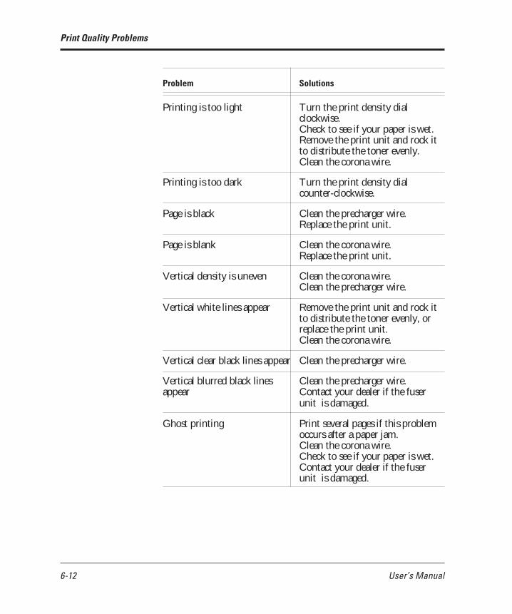
6-12 User’s Manual
Problem Solutions
Printing is too light Turn the print density dialclockwise.Check to see if your paper is wet.Remove the print unit and rock itto distribute the toner evenly.Clean the corona wire.
Printing is too dark Turn the print density dialcounter-clockwise.
Page is black Clean the precharger wire.Replace the print unit.
Page is blank Clean the corona wire.Replace the print unit.
Vertical density is uneven Clean the corona wire.Clean the precharger wire.
Vertical white lines appear Remove the print unit and rock itto distribute the toner evenly, orreplace the print unit.Clean the corona wire.
Vertical clear black lines appear Clean the precharger wire.
Vertical blurred black lines Clean the precharger wire.appear Contact your dealer if the fuser
unit is damaged.
Ghost printing Print several pages if this problemoccurs after a paper jam.Clean the corona wire.Check to see if your paper is wet.Contact your dealer if the fuserunit is damaged.
Print Quality Problems
08 Chapter 6 07.08.1997, 11:41 Uhr12

User’s Manual 6-13
SOLVINGPROBLEMS
Error Indications
Problem Solutions
Pages have toner stains or If this problem occurs after a papersmudging jam, print several pages.
Clean the paper path.Clean the paper guide before thecorona wire.Clean the corona wire.Replace the cleaner pad.If the fuser unit is damaged, contactyour dealer.
Toner insufficiently adheresto or easily comes off paperwhen you are printing thickor special paper.
Vertical lines appear in solidblack printing, stains appearin the back of a page, orpaper is wrinkled or curled.
Turn the thick paper mode onusing the control panel .
Check if the thick paper mode ison by using the control panel; ifthe mode is on, turn it off.
Errors refer to a problem or condition which requires you to takeaction. The printer shows errors by using the ERROR indicator andthe message display of the control panel. The following table lists theerror indications, explains causes, and suggests solutions.
Message Causes and solutions
BD CYCLE ERROR Cause: Malfunction in the laser unitSolution: If the error recurs, consultyour dealer for service.
COMM.ERROR Cause: Communication errorSolution: Press the button andselect the correct settings of the serialinterface using the control panel setupmode.
Error Indications
08 Chapter 6 07.08.1997, 11:41 Uhr13

6-14 User’s Manual
Message Causes and solutions
COVER OPEN 1 Cause: Incomplete closing of upper doorSolution: Close the upper door.Note: See caution following in this table.
COVER OPEN 2 Cause: Incomplete locking of paper guideinside the rear stackerSolution: Lock the paper guide.Note: See caution following in this table.
COVER OPEN 3 Cause: Incomplete closing of rear unit ofthe optional duplex unit.Solution: Close the rear unit of theduplex unit.
FUSER FAILURE Cause: Malfunction in the fuser unitSolution: If the error recurs, consult yourdealer for service.
INVALID SIMM Cause: Incorrect SIMM card (optionalemulation or font) installedSolution: Press the button.
JOB TIMEOUT Cause: FPS job timeout (This erroroccurs when the FPS card is installed.)Solution: Press the button.
LOAD MFF size Cause: Paper mismatch occurred.LOAD TRAYn size Solution: Set the specified tray to the
correct paper size specified.
MANUAL TIMEOUT Cause: Paper was not inserted into themanual feed slot in the prescribed time.(This error occurs when the FPS card isinstalled.)Solution: Press the button.
MEMORY OVER FLOW Cause: Memory overflow errorSolution: Press the button.
MEMORY SHORTAGE Cause: Insufficient memorySolution: Add RAM board.
MFF NOT INSTALL Cause: No MFF installedSolution: Install the MFF.
Error Indications
08 Chapter 6 07.08.1997, 11:41 Uhr14

User’s Manual 6-15
SOLVINGPROBLEMS
Error Indications
Message Causes and solutions
MOTOR FAILURE n Cause: Malfunction in the feed motor,etc.Solution: If the error recurs, consultyour dealer for service.
NO PROCESS UNIT Cause: No print unit is installed.Solution: Install the print unit.
OVERRUN ERROR Cause: Incomplete in extractingcompressed dataSolution: Press the button.
PAPER JAMn Cause: Paper jam in the specifiedpositionSolution: Clear the jammed paper fromthe following area:0: Pick roller, 1: Entry to paper path2: Paper path, 3: Ejection from paperpath4: Duplex unit
PS ERROR mn Cause: A PostScript errorSolution: If the error recurs, consultyour dealer for service.
Source PAPER OUT Cause: Paper out in the specified papersourceSolution: Supply paper.
STACKER FULL Cause: Paper stacker fullSolution: Remove paper from the paperstacker.
SYSTEM ERROR n Cause: A system error on the controllerboardSolution: If the error recurs, consultyour dealer for service.
TRAYn MISS SET Cause: Paper tray installed incorrectlySolution: Install the paper tray.
TONER EMPTY Cause: Toner runs out.Solution: Replace toner bottle and heatroller cleaner.
08 Chapter 6 07.08.1997, 11:41 Uhr15

6-16 User’s Manual
These conditions, not errors, require you to take action. Thefollowing table lists the message indications, explains causes, andsuggests solutions.
Message Causes and solutions
INSERT size Cause: Printer is ready for paper.Solution: Put paper into manual feedslot.
READY TONER LOW Cause: Toner runs short.Solution: Prepare new toner bottle.
READY REPLACE PARTS Cause: Print unit is near end.Solutions: Replace print unit.Note: Enter menu mode and select ClearWarning. After replacement, be sure topress to perform Clear Warning.
Important:If the upper door is not firmly closed or the paper guide is not in thelocked position, the printer does not work.
Action-required Status Indications
Action-requiredStatusIndications
✍
Paper guideRear stacker
Upper door
08 Chapter 6 07.08.1997, 11:41 Uhr16

User’s Manual 6-17
SOLVINGPROBLEMS
Printer statuses refer to conditions which generally require no actionby you. The following table lists the printer statuses and explainstheir meaning. It does not include messages in menu mode.
Message Meaning
FORM FEED The printer displays this message whenyou press with the DATAindicator off. The printer is printing dataremaining in buffer.
<<<INITIALIZE>>> The printer is initializing. This messageappears whenever you turn on theprinter, close the upper door, or lock thepaper guide.
MENU RESET The printer displays this message whenyou press for five or moreseconds. This reset returns parametersettings in the menu to their factorydefaults except for interface settings aswell as clears error latches, buffered data,and temporary soft fonts.
PRINT FONT The printer displays this message whenyou press for five or moreseconds. The printer is printing the fontreport.
READY The printer is ready to print.
RESET The printer displays this message whenyou press for five or moreseconds. This reset clears error latches,buffered data, and temporary soft fonts.
SELF TEST The printer displays this message whenyou press for five or moreseconds. The printer is printing thestatus report.
WARMING UP The printer is warming up to itsoperating temperature.
Printer Status Indications
Printer StatusIndications
08 Chapter 6 07.08.1997, 11:41 Uhr17

6-18 User’s Manual
WarningMessages
Warning Messages
This printer counts the number of the printed sheets to estimate thelife of the consumables (print unit). The printer indicates thefollowing warning message when and after the count reaches apredetermined value.
READY REPLACE PARTS
When the warning message is indicated, press the button toput the printer offline and press the button to enter menumode. The Clear Warning message appears, indicating the expiredunit by an asterisk. When the print unit is expired, the message is:
<CLEAR WARNING> PRINT UNIT*
However, depending on the print quality, you may not have toreplace print unit because you may suit be satisfied with the printquality.
08 Chapter 6 07.08.1997, 11:41 Uhr18

User’s Manual A-1
FONT SAMPLES
AAPPENDIX
Font Samples
This appendix provides scanned print samples of the fonts resident in thisprinter. Resident fonts are provided separately for two emulation modes:• PCL mode• FPS mode
Bitmapped FontPCL Mode
Scalable Intellifonts
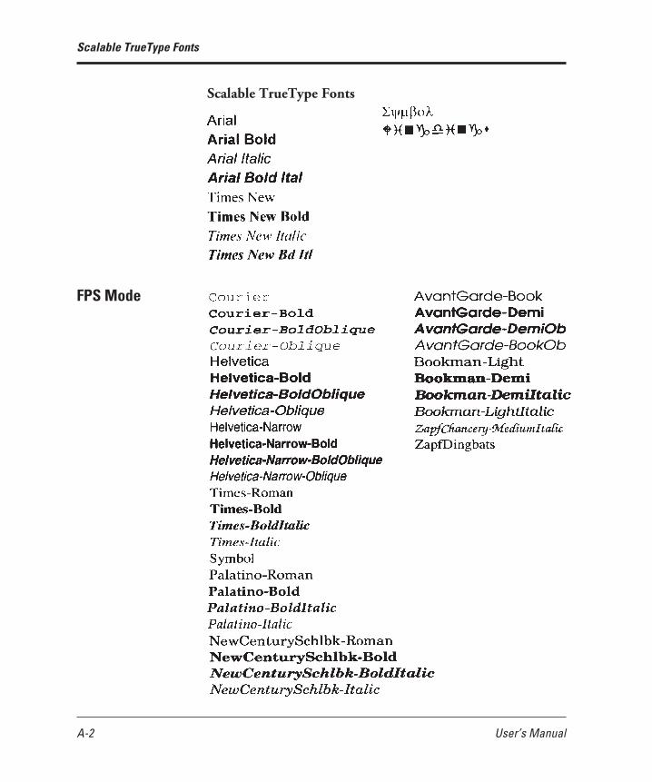
A-2 User’s Manual
Scalable TrueType Fonts
Scalable TrueType Fonts
FPS Mode
09 Appendix A 07.08.1997, 11:42 Uhr2

User’s Manual B-1
SUPPLIES ANDACCESSORIES
BAPPENDIX
Supplies and Accessories
This appendix provides ordering information on supplies requiredfor periodic maintenance as well as optional accessories.
Contact your dealer to order or obtain additional information aboutthe supplies and accessories listed here.
Part name (order number) Description
Toner kit The toner kit contains two toner bottles and(CA04040-C730) two cleaner pads.
Print unit The print unit consists of a photoconductor(CA02758-C400) drum, a developing unit, and a drum
cleaner in a single module.
Supplies
Part name (order number) Description
Memory expansion cards (*1) Allows RAM expansion by oneof the following:
(CA02417-C851) 1 megabyte(CA02417-C852) 2 megabytes(CA02417-C854) 4 megabytes(CA02417-C858) 8 megabytes(CA02758-C856) 16 megabytes(CA04040-C853) 32 megabytes
Accessories
10 Appendix B 07.08.1997, 11:42 Uhr1

B-2 User’s Manual
Accessories
Part name (order number) Description
Serial interface board RS-232C/422A(CA04040-C801)
LocalTalk board 2 AppleTalk compatible(CA04040-C826)
Ethernet board C NetWare & TCP/IPcorresponding
(CA04040-C832) For USA and UK(CA04040-C833) For Europe
Paper trays Adjustable for a different size(CA04040-C70x) 550 sheets (for tray 1)
1: A4, 2: Letter, 3: Legal(CA02758-C73x) 500 sheets (for tray 2)
1: A4, 2: Letter, 3: Legal4: Executive, 6: A5
Paper feeders Feeder unit with/without a paper(CA02758-C75x) tray adjustable for a different size
European/Asian spec 0: No tray, 5: A4 size trayUSA spec 1: No tray, 6: Letter size tray
Canadian spec 2: No tray, 7: Letter size tray
Duplex unit Two-sided printing mechanism(CA04040-C750) For Europe(CA04040-C751) For USA(CA04040-C751) For Canada
*1 When printing on Legal size paper at 600 dpi or printing largeimage data, we recommend the installation of additional memorycards of 10MB or more. (If you cannot get memory cards, selectOn for the banding mode in the FPS menu in menu mode usingthe control panel.)
10 Appendix B 07.08.1997, 11:42 Uhr2

User’s Manual C-1
SPECIFICATIONS
CAPPENDIX
Specifications
Specification Description
Printing technology Semiconductor laser + electrophotography
Emulations Standard: Hewlett-Packard LaserJet 4 (PCL5e)PostScript level-2 compatible
Switching: Automatic or by the control panel
Dimensions Width: 376.5 mm (14.8 inches)Depth: 640 mm (25.2 inches) with MFFHeight: 289 mm (11.4 inches)Weight: 18 kg (39.7 pounds) with MFF
* MFF includes paper support wire.
Power requirements 120 VAC , 50 or 60 Hz (USA)220 to 240 VAC , 50 or 60 Hz (Europe)Consumption:Maximum 600 W(full option) Average during operating
450 W or less30 W or less during sleep mode
Environmental Temperature: 10° to 35°C (50° to 95°F) duringrequirements operating
0° to 40°C (32° to 104°F) duringstorage
Humidity: 20% to 80% relative humidity(non-condensing) during
operating and storageMaximum wet bulb 29°C (84°F)
Acoustic noise Sound pressure level (front, bystander position)Printing: 48 dBA without duplex unit
51 dBA with duplex unitSleep mode: Background noise levelDeclared noise emissions in accordancewith ISO9296 and ISO7779
11 Appendix C 07.08.1997, 11:42 Uhr1
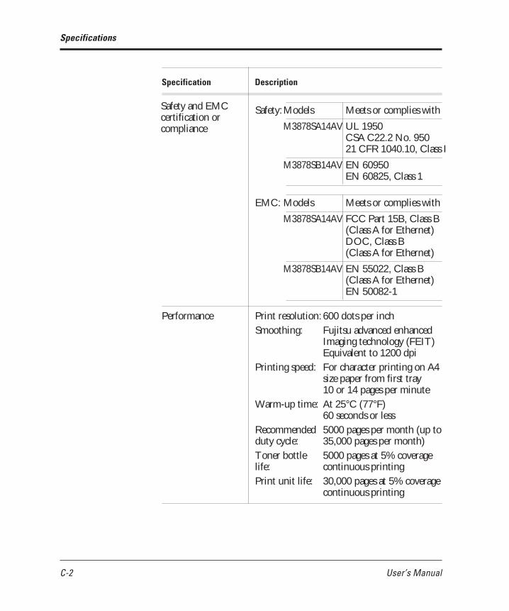
C-2 User’s Manual
Specification Description
Safety: Models Meets or complies with
M3878SA14AV UL 1950CSA C22.2 No. 95021 CFR 1040.10, Class I
M3878SB14AV EN 60950EN 60825, Class 1
EMC: Models Meets or complies with
M3878SA14AV FCC Part 15B, Class B(Class A for Ethernet)DOC, Class B(Class A for Ethernet)
M3878SB14AV EN 55022, Class B(Class A for Ethernet)EN 50082-1
Performance Print resolution: 600 dots per inchSmoothing: Fujitsu advanced enhanced
Imaging technology (FEIT)Equivalent to 1200 dpi
Printing speed: For character printing on A4size paper from first tray10 or 14 pages per minute
Warm-up time: At 25°C (77°F)60 seconds or less
Recommended 5000 pages per month (up toduty cycle: 35,000 pages per month)Toner bottle 5000 pages at 5% coveragelife: continuous printingPrint unit life: 30,000 pages at 5% coverage
continuous printing
Specifications
Safety and EMCcertification orcompliance
11 Appendix C 07.08.1997, 11:42 Uhr2

User’s Manual C-3
SPECIFICATIONS
Specification Description
Computer interface Standard: Parallel (Centronics), conforming toIEEE 1284 (Compatible and Nibblemodes)
Optional: Serial (RS-232C/422A)LocalTalk (AppleTalk compatible)Ethernet C (NetWare & TCP/IPcorresponding)
Switching: Automatic sensing
Controller Processor: Fujitsu MB86936, 40 MHzRAM: 3 MBSIMM: 1, 2, 4, 8, 16, or 32␣ MB, 2 slots
provided
Fonts Resident: PCL mode46 fonts availableBitmapped
Line PrinterScalable Intellifonts
CG Times, Univers,Univers Condensed,Courier, Letter Gothic,Albertus, Antique Olive,Clarendon Condensed,Coronet, Garamond,Marigold, CG Omega
Scalable TrueTypeArial, Times New Roman,Symbol, Wingdings
FPS mode35 fonts available
Courier, Helvetica,Helvetica Narrow, Times,Symbol, Palatino,New Century Schoolbook,Avant Garde, Bookman,Zapf Chancery,Zapf Dingbats
Soft fonts: Available from independentvendors
Specifications
11 Appendix C 07.08.1997, 11:42 Uhr3

C-4 User’s Manual
Specification Description
Paper Type Single sheet photocopy paper (equivalent toXerox 4024), bond paper, overheadtransparencies (equivalent to 3M 731), andenvelopes. See Chapter␣ 3 for more information.
Size Tray: A4 (210 × 297 mm)A5 (148 × 210 mm)Letter (8.5 × 11 inches)Legal (8.5 × 14 inches)Executive (7.25 × 10.5 inches)
Manual Minimum:feed slot 100 mm wide × 148 mm longand MFF: (3.94 × 5.81 inches)
Maximum:216 mm wide × 360 mm long(8.5 × 14.13 inches)
Weight 60 to 90 g/m2 (16 to 24 pound bond) in tray
60 to 105 g/m2 (16 to 28 pound bond) inmanual feed slot
Input Tray 1: 550 sheets of 0.09 mm thick paper
Manual feed slot: 1 sheet
Tray 2: 500 sheets of 0.09 mm thickpaper (option)
MFF: 100 sheets of 0.09 mm thickpaper or 30 envelopes
Output Stacker: Face down(top cover) 250 sheets of 0.09 mm thick paper
(possible to decrease depending onpaper types and paper curlconditions)
Rear stacker:Face up20 sheets of 0.09 mm thick paper
Rear stacker:Face up(duplex 20 sheets of 0.09 mm thick paperunit)
Specifications
11 Appendix C 07.08.1997, 11:42 Uhr4

User’s Manual GL-1
GLOSSARY
Glossary
Application softwareA program that performs a particular task on a computer. Examplesare word processing, spreadsheet, and database programs.
BaudThe speed of data transmission measured in bits per second. Baudrates apply to data transmission through the printer’s serial interface.Baud is also called baud rate.
For example, 1200 baud is approximately equal to 120 characters persecond.
BitA binary digit, or bit, is the smallest unit of information in acomputer’s memory. A bit can have the value 0 or 1, whichrepresents the OFF and ON state in a computer’s memory. Eightbits equals one byte.
Bit mapAn image representation in which each point in the image isseparately defined. For monochrome images, each point is defined bya single unit of information. For color images, each point is definedby several units of information, representing the different colorelements.
The characters produced by a dot matrix printer are a kind of bitmap. Each character image is created by defining the points in thedot matrix as either on or off.
Example:
12 Glossary 07.08.1997, 11:42 Uhr1

GL-2 User’s Manual
Glossary
Bitmapped fontA font in which the character images are defined by bit maps. Withbitmapped fonts, a separate set of definitions is required for eachpoint size. For example, Times 10 point and Times 12 point areconsidered separate fonts. See also Scalable font.
ConfigurationA combination of settings that allows your computer and printer towork together. Some of the necessary settings are in the computer orapplication software, while other settings are in the printer. Forexample, the interface setting must be set the same in both thecomputer and the printer.
Corona wireA fine wire in the printer that gives a positive charge to the paper.This charge causes the toner on the drum to transfer to the paper.
DefaultA setting automatically used when you or your application softwaredo not make a selection. The settings in effect when you turn on orreset the printer are called power-on defaults. See also Factory default.
DensityThe darkness of the image as it appears on the page. If the density istoo dark, the small white areas inside letters and numbers will befilled in. If the density is too light, pinholes appear in black areas.Print density can be adjusted with the print density dial.
Downloadable fontA font that is transferred (downloaded) to the printer’s memorywhen or before it is needed. Before they are transferred,downloadable fonts are stored on font cards, floppy disks, or thecomputer’s hard disk. Downloadable fonts are also called soft fonts.
EmulationThe ability of one printer to understand the command set of anotherprinter. Emulations may be built into a printer’s memory or may besupplied on optional plug-in emulation cards or cartridges.
12 Glossary 07.08.1997, 11:42 Uhr2

User’s Manual GL-3
GLOSSARY
Glossary
EthernetA communication hardware for a high-speed network: developed byXerox Corporation.
Factory defaultThe settings that are programmed into a printer at the factory. Theprinter uses these settings unless they are replaced by user selectedsettings entered from the control panel or through applicationsoftware.
Flow controlSee Serial protocol.
FontA complete set of characters and symbols in one size, typeface, andstyle. Size refers to the character height, and is usually measured inpoints (1/72 inch). Typeface refers to the character design, such asCourier, Times, or Helvetica. Style refers to the characterappearance, such as Italic or Bold. Typical examples of fonts are 12-point Courier Bold, and 10-point Times Italic.
Fuser unitOne of the internal parts of a page printer. The fuser unit bonds thetoner to the paper. It consists of a heat roller and a pressure rollerthat the paper passes under after toner has been applied.
Hex dumpA special printout used for troubleshooting. A hex dump shows alldata sent by the computer to the printer, including controlcharacters. The data in a hex dump is expressed in hexadecimalformat.
InitializationResets the printer to its power-on defaults. Initialization clears theprint buffer of any data and places the printer online. See also Reset.
12 Glossary 07.08.1997, 11:42 Uhr3

GL-4 User’s Manual
InterfaceThe means by which information is transferred from one part of asystem to another. For example, the cable between the printer andthe computer is an interface.
ISO symbol setISO stands for “International Organization for Stanardization”. AnISO symbol set contains special international characters that replacethe following twelve ASCII characters: #, $, @, [, \, ], ^, 9, {, |. }, and~. ISO symbols sets are available for most European languages,Chinese, and Japanese.
LocalTalkA protocol for an easy AppleTalk that connects devices andcomputers in a Macintosh system, developed by Apple Computer.
MarginThe space at the edges of a page in which no printing occurs. Thereare four margins: left, right, top, and bottom. In applicationsoftware, margins are usually expressed in inches, centimeters, orpoints. In printer commands, left and right margins are specified ascolumns, while top and bottom margins are specified as lines.
Page printers have a minimum margin, typically of about .2 inch (5mm), on all four sides, called the nonprint margin. No printingoccurs in this margin. If the application software specifies a marginof 0, actual printing begins at the edge of the nonprint margin. Seealso Printable area.
MarkVisionA printer management integrated software which monitors printerstatus, displays optional printer’s features, spools print data, andcooperates with printer drivers. It also displays the virtual printercontrol panel to allow remote operation of printers.
Glossary
12 Glossary 07.08.1997, 11:42 Uhr4

User’s Manual GL-5
GLOSSARY
Glossary
OrientationThe direction of print on a page. Printing such that the shorter edgesof the paper are at the top and bottom is called portrait orientation.Printing such that the longer edges of the paper are at the top andbottom is called landscape orientation.
Example:
Page description languageA set of codes that describe the placement of text and graphics on apage. Page Control Language (PCL), the language used by HPLaserJet printers, and Postscript are examples of page descriptionlanguages.
Page protectA printer feature that reserves a block of printer memory exclusivelyfor text and graphics data. Page protect prevents memory overflowerrors when printing very dense text or complex graphics. However,page protect also reduces the amount of printer memory available fordownloadable fonts.
Parallel interfaceA connection between the computer and printer in which data istransferred simultaneously through multiple wires. A parallelinterface is faster than a serial interface, but the distance over whichit can send data is limited. The Centronics interface is a type ofparallel interface. See also Serial interface.
Photoconductive drumThe part inside a page printer on which the image is created before itis transferred to the paper.
Portrait Landscape
12 Glossary 07.08.1997, 11:42 Uhr5

GL-6 User’s Manual
Glossary
PostscriptSee Page description language.
Precharger wireA fine wire in the printer’s process cartridge that imparts an electricalcharge to the photoconductive drum. The charge makes the drumsensitive to light.
Printable areaThe area of the physical page in which the printer is able to print.Page printers have a nonprint margin, typically about .2 inch (5 mm)wide, at each edge of the paper. The printable area is the spacewithin these margins. See also Margin.
Example:
Printer driverA set of instructions in application software that translates formattingchoices into printer commands. When installing the application, theuser identifies the type of printer being used so the application knowswhich printer driver to use.
Print unitA maintenance package consisting of the photoconductive drum,developing unit, toner, and drum cleaner.
ResetClears the print buffer and places the printer online. Unlikeinitialization, reset leaves the currently selected settings in effect.That is, reset does not restore the power-on defaults. See alsoInitialization.
Printablearea
←→
↓↑ Nonprint margins
12 Glossary 07.08.1997, 11:42 Uhr6

User’s Manual GL-7
GLOSSARY
Glossary
ResolutionThe fineness of the printing. Resolution depends on the number ofdots per inch. High resolution (with more dots) is finer and moreprecise than low resolution, which is coarser with rougher edges.
Scalable fontA font capable of printing in any point size. Scalable fonts are storedon the computer’s hard disk. Each font consists of charactertemplates that are used by the accompanying font utility software tocreate the characters in the desired point size.
Some font utilities create a complete set of characters in the desiredsize and send the complete set to the printer. Other utilities createand send only the individual characters as they are needed, whichconserves printer memory.
Serial interfaceA connection between the computer and printer in which data istransmitted sequentially over a single wire. A serial interface is slowerthan a parallel interface, but it can send data over a much greaterdistance. The RS-232C interface is a type of serial interface. See alsoParallel interface.
Serial protocolA set of rules used by the computer and the printer to regulate theflow of data between them.
Symbol setThe set of characters used in a font. Most symbol sets containstandard letters, numbers, and punctuation. Symbol sets differ in theaccented characters, line drawing characters, and special symbols theycontain. ASCII, Roman-8 and PC-8 and examples of symbol sets.
Symbol sets are also called character sets, which is the term usuallyused with dot matrix printer fonts. See also ASCII character set; ISOsymbol set.
12 Glossary 07.08.1997, 11:42 Uhr7

GL-8 User’s Manual
Glossary
TonerElectrically charged carbon particles that adhere to charged areas onthe photoconductive drum to produce an image pattern. The carbonpattern is transferred to the paper and melted by the fuser unit toform a permanent image on the paper.
Transfer unitThe part inside a page printer that transfers the image from thephotoconductive drum to the paper.
12 Glossary 07.08.1997, 11:42 Uhr8

User’s Manual IN-1
INDEX
Index
A
AC power conditions 1–4 to 1–5Accessories, ordering information B–1Adjusting print density 1–27AUTOEXEC.BAT file 4–7
B
Bitmapped fonts, residentavailable fonts C–3samples of A–1
Button functions 3–3 to 3–4
C
Cable, interface 1–17, 4–5, 4–8, 4–9Cautionary notes
electrostatic damage 1–5, 1–7, 1–18, 4–1,4–3, 4–5, 4–8, 4–9, 4–11, 5–1, 6–1
paper jams 6–2printing off the physical page 3–31print unit
exposing to light 1–7, 5–1removing protective sheets 1–7, 5–12touching drum 1–7, 5–12, 5–17turning upside down 5–9
status report, interrupting printout of 3–6Centronics interface
See Parallel interfaceChanging the paper tray size
optional tray 4–12standard tray 3–25
Cleaner and cleaner pad 1–10, 5–5Connecting power cord 1–16Connecting printer to computer 1–17 to 1–19CONT. button 3-4, 3–5Control panel
buttons 3–3 to 3–4indicators 3–2
Controller specifications C–2Conventions used in this manual viCorona wire
cleaning procedure 5–10when to clean 5–2, 6–10
D
Dark printoutSee Print density adjustment
DATA indicator 3–2Density
See Print density dial; Print quality problemsDouble-side printing 3–32Duplex unit 4–15
E
Emulation, selecting 1–20ENTER button 3–4, 3–10, 3–11, 3–12, 3–13Envelopes 3–24Error indications 6–11 to 6–13ERROR indicator 3–2Ethernet interface 4–9
F
Factory defaults of PPMENU 2–4 to 2–5Floppy disks, attached vFont report 3–8 to 3–9Font samples, resident A–1 to A–2
13 Index 07.08.1997, 11:42 Uhr1

IN-2 User’s Manual
Index
Letterhead 3–23, 3–32Light printout
See Print density adjustmentLocalTalk interface 4–7Location of printer 1–4Loading paper 1–12
M
Maintenanceperiodic routine 5–2 to 5–17
cleaning corona wire 5–10cleaning paper path 5–10cleaning precharger wire 5–17replacing cleaner pad 5–5replacing print unit 5–7 to 5–16replacing toner bottle 5–2 to 5–5when to perform 5–2
preventive 5–1Manual feed
selecting 3-10using 3–29 to 3–30
MarkVisioninstallation 2–6operating environments vi
Memory expansion cardsinstallation procedure 4–1 to 4–3ordering information B–1
MENU button 3–4, 3–5, 3–12Menu mode
functions 3–12 to 3–16items 3–16structure and how to use buttons 3–12submenus, items, options 3–13
Menu screenMarkVision 2–7PPMENU 2–3
Message display 3–3Message language 3–5MFF PAPER SIZE button 3–4, 3–11Minus (–) button 3–4, 3–10, 3–11, 3–12, 3–13
Font specifications C–3FORM FEED button 3–4, 3–5Front panel
See Control panelFuser unit
error condition 6–10when to replace 6–12
H
HP LaserJet 4 vHumidity limitations 1–4, C–1
I
Indicators 3–2Installation
cleaner and cleaner pad 1–10interface boards 4–4 to 4–10multi-function feeder 1–15 to 1–16paper feeder 4–10print unit 1–7printer driver 1–21RAM card 4–1 to 4–3toner bottle 1–7
InterfaceEthernet 4–9 to 4–10LocalTalk 4–7 to 4–8parallel 1–18serial 4–5 to 4–7types and merits 1–17, 1–18
Inventory of printer 1–6
L
Labels 3–25Landscape orientation
See Orientation: pageLanguage of message display 3–5LaserJet 4
See HP LaserJet 4
13 Index 07.08.1997, 11:42 Uhr2

User’s Manual IN-3
INDEX
Index
different size of 4–15loading paper 1–12 to 1–13ordering information B–2maximum number of sheets C–4selecting 3–10
Parallel interface 1–17 to 1–18Parts of printer 1–1Periodic routine maintenance 5–2 to 5–17Plus (+) button 3–4, 3–10, 3–11, 3–12, 3–13Portrait orientation
See Orientation: pagePower cord connection procedure 1–16 to 1–17POWER indicator 3–2PPMENU
factory defaults 2–4 to 2–5installation 2–2operating environments vi
Precharger wirecleaning procedure 5–17when to clean 5–2, 6–10
Preprinted sheets 3–23Preventive maintenance 5–1Print density adjustment 1–27Print density dial, when to adjust 6–10PRINT FONT button 3–4, 3–8Print parameter factory default settings
(PPMENU)2–4 to 2–5
Print quality problems 6–9 to 6–11Print unit
cautionary notesexposing to light 1–7, 5–1removing protective sheets 5–12touching drum 1–7, 5–9, 5–12, 5–17turning upside down 5–9
counter resetting 5–15installation procedure 1–7 to 1–9,
5–12 to 5–14ordering information B–1procedure to remove 5–8 to 5–9when to replace 5–2, 6–10
MODE.COM file 4–7Multi-function feeder (MFF)
installing 1–15 to 1–16selecting 3–10setting paper size 3–11
O
ONLINE indicator 3–2Operating environments viOperational problems 6–8Options vOrdering information B–1 to B–2Orientation, page 3–32
P
Page orientation 3–32Paper
feeding manually 3–29 to 3–30loading in tray 1–12 to 1–13maximum and minimum sizes 3–21printing on nonstandard sizes 3–31 to 3–32sizes and types 3–20 to 3–25specifications C–4
Paper feeder 4–10Paper guide before corona wire, cleaning 5–11Paper jams
avoiding 6–8clearing 6–1 to 6–7
Paper margin 3–22Paper path
cleaning procedure 5–10ordinary and straight 1–3when to clean 5–2, 6–10
Paper size of MFF, setting 3–11Paper source, selecting 3–10Paper trays
changing the paper tray sizeoptional tray 4–12standard tray 3–25
13 Index 07.08.1997, 11:42 Uhr3

IN-4 User’s Manual
Index
Printerconnecting to computer 1–17 to 1–18nomenclature 1–1 to 1–3operational problems 6–8repacking 5–18resetting 3–4, 3–6
Printer driverscontrol of print parameters by 2–1installation 1–21 to 1–25
Printer status indications 6–15Printing
a test page offline 1–19feeding sheets manually 3–29 to 3–30on letterhead 3–23, 3–32on nonstandard size papers and envelopes
3–31on transparency material 3–23 to 3–24supported paper types and sizes
3–20 to 3–24, C–4Printing a trial document with a printer driver
1–26Printing area 3–22Printing performance C–2Problems
error indications 6–11 to 6–13operational 6–8paper jams 6–1 to 6–7print quality 6–9when printing a trial document 1–28
R
Ready, definition of 3–3Rear stacker setting up 3–30Repacking the printer 5–18RESET button 3–4, 3–6RESET MENU button 3–4, 3–12Resetting
the print unit counter 5–15the printer 3–6
Resident fonts, samples of A–1 to A–2RS-232C serial interface
See Serial interface
S
Scalable fonts, residentavailable fonts C–3samples of A–2
SELF TEST button 3–4, 3–6Serial interface
how to connect 4–5 to 4–6parameter setting 4–6 to 4–7
Setting upprinter in menu mode 3–12rear stacker 3–30
Specifications C–1 to C–4Status indication 6–14, 6–15Status report
Action required 6–15No action required 6–13
Supplies, ordering information B–1
T
Temperature limitations 1–4, C–1Toner bottle
installation procedure 1–7 to 1–9ordering information B–1replacement procedure 5–2 to 5–5
Transparencies 3–23TRAY SELECT button 3–4, 3–10Two-sided printing 3–32
W
Warning messages 6–16
13 Index 07.08.1997, 11:42 Uhr4
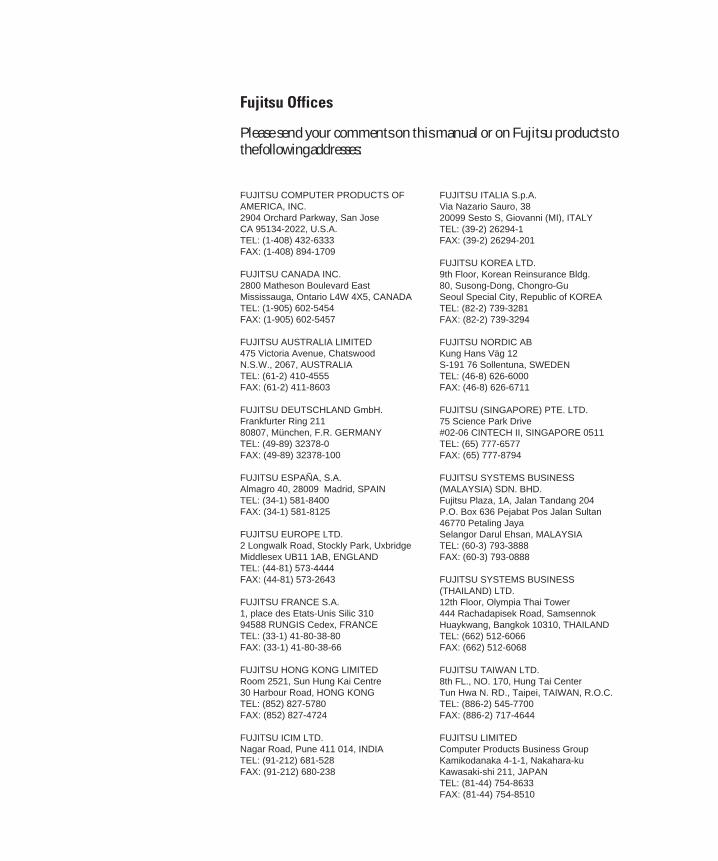
Fujitsu Offices
Please send your comments on this manual or on Fujitsu products tothe following addresses:
FUJITSU COMPUTER PRODUCTS OFAMERICA, INC.2904 Orchard Parkway, San JoseCA 95134-2022, U.S.A.TEL: (1-408) 432-6333FAX: (1-408) 894-1709
FUJITSU CANADA INC.2800 Matheson Boulevard EastMississauga, Ontario L4W 4X5, CANADATEL: (1-905) 602-5454FAX: (1-905) 602-5457
FUJITSU AUSTRALIA LIMITED475 Victoria Avenue, ChatswoodN.S.W., 2067, AUSTRALIATEL: (61-2) 410-4555FAX: (61-2) 411-8603
FUJITSU DEUTSCHLAND GmbH.Frankfurter Ring 21180807, München, F.R. GERMANYTEL: (49-89) 32378-0FAX: (49-89) 32378-100
FUJITSU ESPAÑA, S.A.Almagro 40, 28009 Madrid, SPAINTEL: (34-1) 581-8400FAX: (34-1) 581-8125
FUJITSU EUROPE LTD.2 Longwalk Road, Stockly Park, UxbridgeMiddlesex UB11 1AB, ENGLANDTEL: (44-81) 573-4444FAX: (44-81) 573-2643
FUJITSU FRANCE S.A.1, place des Etats-Unis Silic 31094588 RUNGIS Cedex, FRANCETEL: (33-1) 41-80-38-80FAX: (33-1) 41-80-38-66
FUJITSU HONG KONG LIMITEDRoom 2521, Sun Hung Kai Centre30 Harbour Road, HONG KONGTEL: (852) 827-5780FAX: (852) 827-4724
FUJITSU ICIM LTD.Nagar Road, Pune 411 014, INDIATEL: (91-212) 681-528FAX: (91-212) 680-238
FUJITSU ITALIA S.p.A.Via Nazario Sauro, 3820099 Sesto S, Giovanni (MI), ITALYTEL: (39-2) 26294-1FAX: (39-2) 26294-201
FUJITSU KOREA LTD.9th Floor, Korean Reinsurance Bldg.80, Susong-Dong, Chongro-GuSeoul Special City, Republic of KOREATEL: (82-2) 739-3281FAX: (82-2) 739-3294
FUJITSU NORDIC ABKung Hans Väg 12S-191 76 Sollentuna, SWEDENTEL: (46-8) 626-6000FAX: (46-8) 626-6711
FUJITSU (SINGAPORE) PTE. LTD.75 Science Park Drive#02-06 CINTECH II, SINGAPORE 0511TEL: (65) 777-6577FAX: (65) 777-8794
FUJITSU SYSTEMS BUSINESS(MALAYSIA) SDN. BHD.Fujitsu Plaza, 1A, Jalan Tandang 204P.O. Box 636 Pejabat Pos Jalan Sultan46770 Petaling JayaSelangor Darul Ehsan, MALAYSIATEL: (60-3) 793-3888FAX: (60-3) 793-0888
FUJITSU SYSTEMS BUSINESS(THAILAND) LTD.12th Floor, Olympia Thai Tower444 Rachadapisek Road, SamsennokHuaykwang, Bangkok 10310, THAILANDTEL: (662) 512-6066FAX: (662) 512-6068
FUJITSU TAIWAN LTD.8th FL., NO. 170, Hung Tai CenterTun Hwa N. RD., Taipei, TAIWAN, R.O.C.TEL: (886-2) 545-7700FAX: (886-2) 717-4644
FUJITSU LIMITEDComputer Products Business GroupKamikodanaka 4-1-1, Nakahara-kuKawasaki-shi 211, JAPANTEL: (81-44) 754-8633FAX: (81-44) 754-8510
14 Inside back cover 07.08.1997, 11:42 Uhr1


![MSDS DFW20 Toner - fujitsu.com · Product name: DFW20 (Toner) [LOCA02758-0351] ... 8.3 Personal protective outfit : ... Hitachi Metals Ltd.](https://static.fdocuments.in/doc/165x107/5acc4c157f8b9a63398cbc80/msds-dfw20-toner-name-dfw20-toner-loca02758-0351-83-personal-protective.jpg)


