TM 11-6625-2847-14&P TECHNICAL MANUAL OPERATOR'S ... · technical manual operator's,...
55
TM 11-6625-2847-14&P TECHNICAL MANUAL OPERATOR'S, ORGANIZATIONAL, DIRECT SUPPORT AND GENERAL SUPPORT MAINTENANCE MANUAL (INCLUDING REPAIR PARTS AND SPECIAL TOOLS LIST) FOR FREQUENCY COMB GENERATOR SG-1129/U (HP-8406A) (NSN 6625-00-937-3525) HEADQUARTERS, DEPARTMENT OF THE ARMY JUNE 1980
Transcript of TM 11-6625-2847-14&P TECHNICAL MANUAL OPERATOR'S ... · technical manual operator's,...

TM 11-6625-2847-14&P
TECHNICAL MANUAL
OPERATOR'S, ORGANIZATIONAL, DIRECT SUPPORT AND GENERAL SUPPORT
MAINTENANCE MANUAL
(INCLUDING REPAIR PARTS AND SPECIAL TOOLS LIST)
FOR
FREQUENCY COMB GENERATOR SG-1129/U
(HP-8406A)
(NSN 6625-00-937-3525)
HEADQUARTERS, DEPARTMENT OF THE ARMY
JUNE 1980

WARNING
115/230 VAC and DC supply wires areexposed when either top or bottominstrument cover is removed.
WARNING
If this instrument is to be energizedthrough an autotransformer (forvoltage reduction), make sure thecommon terminal is connected to theearthed pole of the power source.
BEFORE SWITCHING ON THEINSTRUMENT, the protective earthterminals of the instrument must beconnected to the protectiveconductor of the mains power cord.The mains plug shall only beinserted in a socket outlet providedwith protective earth contact. Theprotection must not be negated byusing an extension cord (power (cab)without a protective groundingconductor.
Any interruption of the protective(grounding) conductor, inside oroutside the instrument, ordisconnection of the protective earthterminal is likely to make thisinstrument dangerous. Intentionalinterruption of the earth ground isprohibited.
Servicing this instrument oftenrequires that you work with theinstrument's protective coversremoved and with ac powerconnected. Be very careful; theenergy at many points in theinstrument may, if contacted, causepersonal injury.
With the ac power cable connected,the ac line voltage is present at theterminals of the power line moduleand at the LINE power switch. Bevery careful. Bodily contact with thisvoltage can be fatal.
CAUTION
BEFORE SWITCHING ON THISINSTRUMENT, make sureinstrument's ac input is set to thevoltage of the ac power source.
BEFORE SWITCHING ON THISINSTRUMENT, make sure that alldevices connected to the instrumentare connected to the protective earthground.
BEFORE SWITCHING ON THISINSTRUMENT, make sure the linepower (mains) plug is connected to athree-conductor line power outletthat has a protective (earth) ground.(Grounding one conductor of a two-conductor outlet is not sufficient.
BEFORE SWITCHING ON THISINSTRUMENT, make sure the ac linefuse is of the required current ratingand type (normal-blow, time-delay,etc.).


TM 11-6625-2847-14&P
This manual contains copyrighted material reproduced by permissionof the Hewlett-Packard Company. All rights reserved.
TECHNICAL MANUAL HEADQUARTERSDEPARTMENT OF THE ARMY
No. 11-6625-2847-14&P Washington, DC 26 June 1980
OPERATOR'S, ORGANIZATIONAL, DIRECT SUPPORT, ANDGENERAL SUPPORT MAINTENANCE MANUAL
INCLUDING REPAIR PARTS AND SPECIAL TOOLS LISTFOR
FREQUENCY COMB GENERATOR SG-1129/U(HP-8406A)
(NSN 6625-00-937-3525)CURRENT AS OF 21 DECEMBER 1979
REPORTING ERRORS AND RECOMMENDING IMPROVEMENTS
You can help improve this manual. If you find any mistakes or if you know of a way to improve theprocedures, please let us know. Mail your letter, DA Form 2028 (Recommended Changes toPublications and Blank Forms), or DA Form 2028-2 located in back of this manual direct to: Commander,US Army Communications and Electronics Materiel Readiness Command and Fort Monmouth, ATTN:DRSEL-ME-MQ, Fort Monmouth, New Jersey 07703. A reply will be furnished to you.
TABLE OF CONTENTSPage
Section 0 INTRODUCTION
0-1 Scope ........................................................................................................................................ 0-10-2 Indexes of Publications ............................................................................................................. 0-10-3 Maintenance Forms, Records, and Reports................................................................................ 0-10-4 Administrative Storage............................................................................................................... 0-20-5 Destruction of Army Electronics Materiel .................................................................................... 0-20-6 Reporting Equipment Improvement Recommendations (EIR)..................................................... 0-2
_______________This manual is an authentication of the manufacturer's commercial literature which, through usage, has been found tocover the data required to operate and maintain this equipment. The manual was not prepared in accordance withmilitary specifications; therefore, the format has not been structured to consider categories of maintenance.
i
Model 8406A Table of Contents
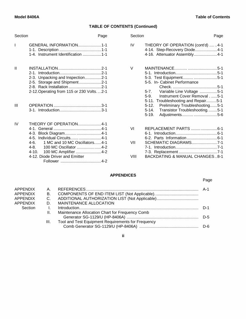
TABLE OF CONTENTS (Continued)
Section Page
I GENERAL INFORMATION....................1-11-1. Description ....................................1-11-4. Instrument Identification ................1-1
II INSTALLATION.....................................2-12-1. Introduction....................................2-12-3. Unpacking and Inspection..............2-12-5. Storage and Shipment ...................2-12-8. Rack Installation ............................2-12-12.Operating from 115 or 230 Volts. ...2-1
III OPERATION .........................................3-13-1. Introduction....................................3-1
IV THEORY OF OPERATION....................4-14-1. General .........................................4-14-3. Block Diagram.......... .....................4-14-5. Individual Circuits....... ...................4-14-6. 1 MC and 10 MC Oscillators......4-14-8. 100 MC Oscillator .....................4-24-10. 100 MC Amplifier ......................4-24-12. Diode Driver and Emitter
Follower ...................................4-2
Section Page
IV THEORY OF OPERATION (cont'd) .... ..4-14-14. Step-Recovery Diode...................4-14-16. Attenuator Assembly....................4-1
V MAINTENANCE........... .........................5-15-1. Introduction....................................5-15-3. Test Equipment......... ....................5-15-5. In- Cabinet Performance
Check. ......................................5-15-7. Variable Line Voltage ...............5-15-9. Instrument Cover Removal . .....5-15-11. Troubleshooting and Repair.........5-15-12. Preliminary Troubleshooting......5-15-14. Transistor Troubleshooting. .......5-15-19. Adjustments.......... ....................5-6
VI REPLACEMENT PARTS ........ ..............6-16-1. Introduction....................................6-16-2. Parts Information ..........................6-1
VII SCHEMATIC DIAGRAMS......................7-17-1. Introduction....................................7-17-3. Replacement .................................7-1
VIII BACKDATING & MANUAL CHANGES..8-1
APPENDICESPage
APPENDIX A. REFERENCES................................................................................................. A-1APPENDIX B. COMPONENTS OF END ITEM LIST (Not Applicable)......................................APPENDIX C. ADDITIONAL AUTHORIZATION LIST (Not Applicable)....................................APPENDIX D. MAINTENANCE ALLOCATION
Section I. Introduction....................................................................................................... D-1II. Maintenance Allocation Chart for Frequency Comb
Generator SG-1129/U (HP-8406A) .............................................................. D-5III. Tool and Test Equipment Requirements for Frequency
Comb Generator SG-1129/U (HP-8406A) ................................................... D-6
ii
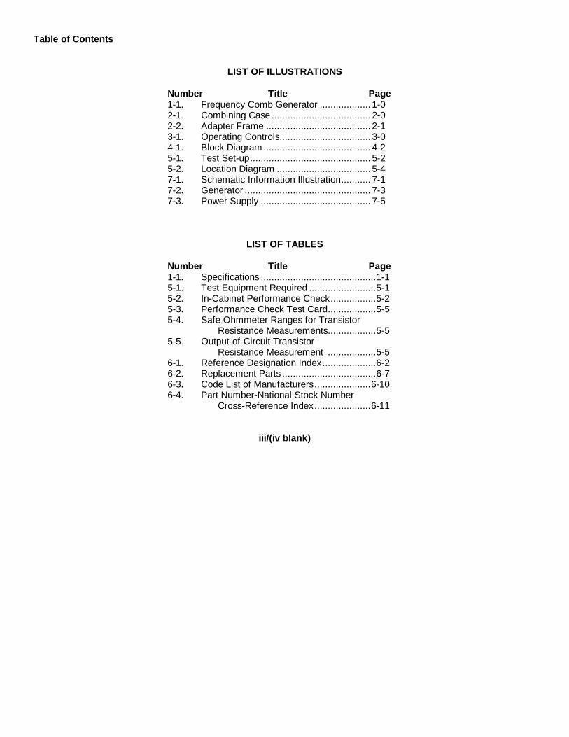
Table of Contents
LIST OF ILLUSTRATIONS
Number Title Page1-1. Frequency Comb Generator ................... 1-02-1. Combining Case ..................................... 2-02-2. Adapter Frame ....................................... 2-13-1. Operating Controls.................................. 3-04-1. Block Diagram........................................ 4-25-1. Test Set-up............................................. 5-25-2. Location Diagram ................................... 5-47-1. Schematic Information Illustration........... 7-17-2. Generator ............................................... 7-37-3. Power Supply ......................................... 7-5
LIST OF TABLES
Number Title Page1-1. Specifications ...........................................1-15-1. Test Equipment Required .........................5-15-2. In-Cabinet Performance Check.................5-25-3. Performance Check Test Card..................5-55-4. Safe Ohmmeter Ranges for Transistor
Resistance Measurements..................5-55-5. Output-of-Circuit Transistor
Resistance Measurement ..................5-56-1. Reference Designation Index....................6-26-2. Replacement Parts ...................................6-76-3. Code List of Manufacturers.....................6-106-4. Part Number-National Stock Number
Cross-Reference Index.....................6-11
iii/(iv blank)

SECTION 0INTRODUCTION
0-1. SCOPE
a. This manual contains instructions for the operation, organizational maintenance, direct support, and generalsupport maintenance of the SG-1129/U Frequency Comb Generator, Hewlett-Packard Model HP-8406A, hereinafterreferred to as the HP-8406A.
b. This TM is an authentication of Hewlett-Packard manual, HP Part No. 08406-90001, printed June 1967 for HP-8406A with serial prefixes 649 and 737. For HP-8406A with serial prefixes other than 649 or 737 this manual must becorrected in accordance with, Backdating Changes for earlier models, or Manual Changes for later models. BackdatingChanges and Manual Changes are located in Section VIII.
c. Appendix A provides a list of applicable references, and Appendix D contains the maintenance allocation chart(MAC). The MAC is current as of 16 May 1979. Table 6-4 contains the part number-national stock number cross-reference index.
0-2. INDEXES OF PUBLICATIONS
a. DA Pam 310-4. Refer to the latest issue of DA Pam 310-4 to determine whether there are new editions,changes, or additional publications pertaining to the equipment.
b. DA Pam 310-7. Refer to DA Pam 310-7 to determine whether there are modification work orders (MWOs)pertaining to the equipment.
0-3. MAINTENANCE FORMS, RECORDS AND REPORTS
a. Reports of Maintenance and Unsatisfactory Equipment. Department of the Army forms and procedures used forequipment maintenance will be those prescribed by TM 38-750, The Army Maintenance Management System.
b. Report of Packaging and Handling Deficiencies. Fill out and forward DD Form 6 (Packaging ImprovementReport) as prescribed in AR 735-11-2/NAVSUPINST 4440.127E/AFR 400-54/MCO 4430.3E and DSAR 4140.55.
c. Discrepancy in Shipment Report (DISREP) (SF 361). Fill out and forward Discrepancy in Shipment Report(DISREP) (SF 361) as prescribed in AR 55-38/NAVSUPINST 4610.33B/AFR 75-18/MCO P4610.19C and DLAR 4500.15.
0-4. ADMINISTRATIVE STORAGE
Before placing this instrument in storage, its complete operability must be verified and all deficiencies corrected byaccomplishing the performance checks and adjustment procedures in Section V of this manual. Troubleshootingprocedures are also provided in Section V to aid in the correction of malfunctions.
0-1

0-5. DESTRUCTION OF ARMY ELECTRONICS MATERIEL
Destruction of Army electronics materiel to prevent enemy use shall be in accordance with TM 750-244-2.
0-6. REPORTING EQUIPMENT IMPROVEMENT RECOMMENDATIONS (EIR)
If your Frequency Comb Generator HP-8406A needs improvement, let us know. Send us and EIR. You, the user,are the only one who can tell us what you don't -Like about your equipment. Let us know why you don't like the design.Tell us why a procedure is hard to perform. Put it on an SF 368 (Quality Deficiency Report). Mail it to: Commander, USArmy Communications and Electronics Materiel Readiness Command and Fort Monmouth, ATTN: DRSEL-ME--MQ, FortMonmouth, New Jersey 07703. We will send you a reply.
0-2
Model 8406A Section IFigure 1-1
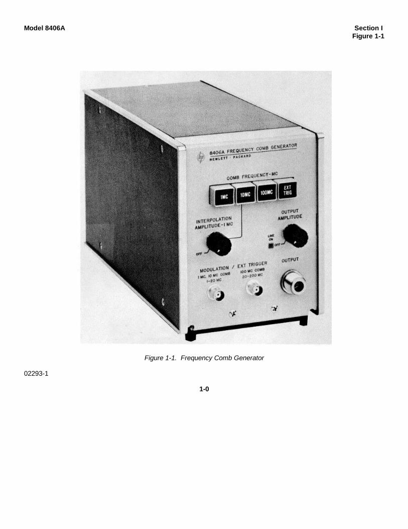
Figure 1-1. Frequency Comb Generator
02293-1
1-0

Model 8406A Section IParagraphs 1-1 to 1-5
SECTION IGENERAL INFORMATION
1-1. DESCRIPTION.1-2. The hp Model 8406A supplies a frequency combwith a selectable spectral line spacing of 1 Mc, 10 Mc,100Mc, or the frequency of an external trigger signal.The frequency comb generated is usable to at least 4Gc.1-3. The Model 8406A provides these additionalfeatures:
a. Output level is continuously variable by a frontpanel control.
b. Interpolation amplitude level is continuouslyvariable by a front panel control.
c. Comb frequency or external trigger frequency isselectable by front panel pushbuttons. This switch willnot permit more than one button to be actuated at a time
to avoid confusion in the output signal.d. Front panel BNC jacks are provided for modulation
and external trigger frequencies.e. A switch is provided on the rear apron to switch the
instrument to 230-volt operation.1-4. INSTRUMENT IDENTIFICATION.1-5. Hewlett-Packard uses a two- section, eight-digitserial number (on instrument rear panel) to identifyinstruments (000-00000). The first three digits are aserial prefix number, and the last five digits refer to aspecific instrument. If the serial prefix on yourinstrument does not appear on the title page of thismanual, there are differences between the manual andyour instrument which are described in a ManualChange sheet included with this manual
Table 1-1. Specifications
Comb Fundamental Frequencies: 1, 10, and 100 Mc,pushbutton selected, generate harmonically relatedsignals usable to beyond 5 Gc.
Comb Frequency Accuracy: ±0.01% (0° to 50°C).Peak Amplitude*:
1 Mc Comb 10 Mc Comb 100 Mc Comb10-500Mc >-80 dBm >-60 dBm -
0.1-1.0 Gc - - >-45 dBm0.5-2.0 Gc >-70 dBm >-50 dBm -
1-2 Gc - - >-35 dBm2-4 Gc >-82 dBm >-62 dBm >-47 dBm*Peak signal level defined in terms of equipmentcw signal level (as measured on hp 8551B/851BSpectrum Analyzer).
OUTPUT AMPLITUDE control permits continuouslevel adjustment.
Comb Output Connector: Type N female, source im-pedance approximately 50 ohm.
Maximum External Signal at Comb Output: Signalsexceeding 1 watt (pk and av) may cause damage.
Interpolation Function: 10- Mc and 1-Mc combs can becombined into primary- secondary comb; Interpola-tion Amplitude control adjusts level of secondary(1 Mc) signal.
External Modulation: External modulation signals can beused to phase modulate any of the combs to producesidebands for interpolation between fixed combmarkersl. BNC female connector.
External Trigger: External signals (normally sine waves)between 1 Mc and 200 Mc can be used to producecombs spaced at frequency of trigger signals2. BNCfemale connector.
1External modulation: Modulation frequencies can be as low as 5 kc. Although the level of modulation voltage required varies with modulating frequency andthe harmonic number of the comb being modulated, the information here will serve as a guide:To produce sidebands approximately 20 db below the main comb marker at the 1 Gc harmonic of the appropriate comb (comb output amplitude at maximum),typical modulation voltages are: 1-2 mv rms at 200 kc for the 1 Mc comb
5-10 mv rms at 2 Mc for the 10 Mc comb50-100 mv rms at 20 Mc for the 100 Mc comb
Signals greater than 5v rms at modulation input may cause damage.2External Trigger: Typical input signal levels to generate externally triggered combs at the frequency of the external trigger are in the range of 1-3 volts rms.Input signals greater than 5 volts rms may cause damage. With input triggers in the 1-20 Mc frequency span, the OUTPUT AMPLITUDE control of the8406A can be used to adjust the output comb level. When using signals in the frequency span from 20-200 Mc, output comb amplitude is a function of theinput signal level.
02293-21-1

Section II Model 8406AFigure 2-1
Figure 2-1. Combining Case02293-1
2-0
Model 8406A Section IIParagraphs 2-1 to 2-14
SECTION IIINSTALLATION
2-1. INTRODUCTION.
2-2. This section contains information on unpacking,inspection, repacking, storage and installation.
2-3. UNPACKING AND INSPECTION.
2-4. Inspect instrument for shipping damage as soon asit is unpacked. Check for broken knobs and con-nectors; inspect cabinet and panel surfaces for dentsand scratches. A performance check is given in Table5-2.
DELETED
2-5. STORAGE AND SHIPMENT.
2-6. DELETED
2-8. RACK INSTALLATION.
2-9. When the Model 8406A is to be rack-mounted, acombining case (Paragraph 2-10) or adapter frame(Paragraph 2-11) is required. The two methods for rackmounting are discussed in the following paragraphs.
2-10. COMBINING CASE. The combining case (hp1051A) shown in Figure 2-1 is a full-module unit whichaccepts varying combinations of submodule units suchas the 1/3 module Model 8406. The combining casecan be used as a bench model or it can be rack-mounted. A rack-mounting kit (hp part number 5060-0777) is supplied to rack mount the combining case.Instructions for using the case are given in Figure 2-1.When only one-third of the case is used, a blankfillerpanel (hp part number 5060-0793) is available toenclose the unused front panel space.
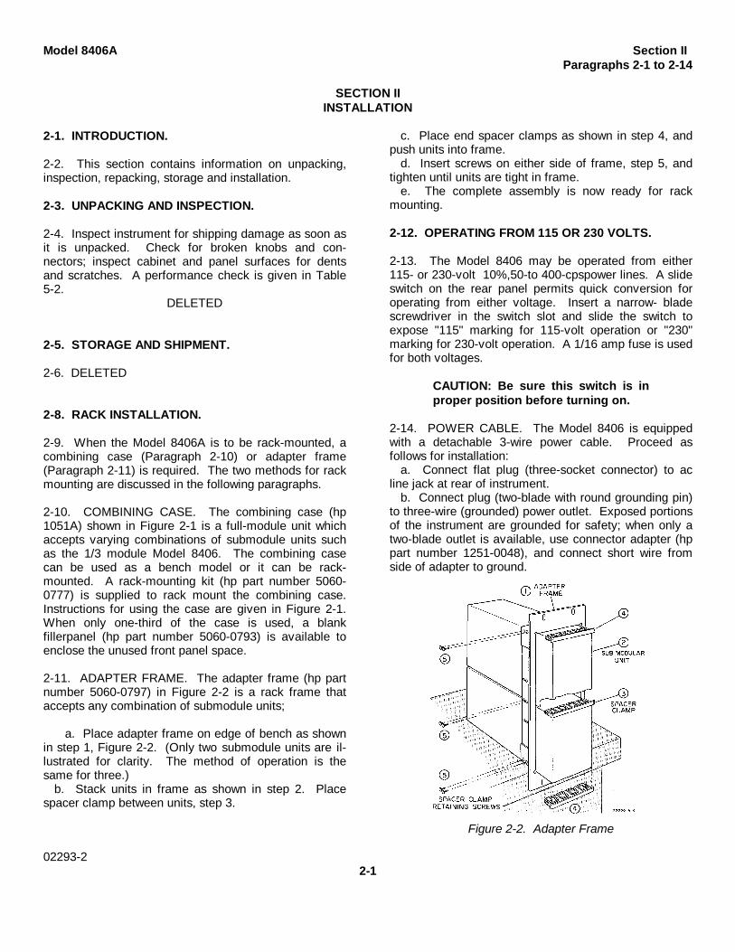
2-11. ADAPTER FRAME. The adapter frame (hp partnumber 5060-0797) in Figure 2-2 is a rack frame thataccepts any combination of submodule units;
a. Place adapter frame on edge of bench as shownin step 1, Figure 2-2. (Only two submodule units are il-lustrated for clarity. The method of operation is thesame for three.)
b. Stack units in frame as shown in step 2. Placespacer clamp between units, step 3.
c. Place end spacer clamps as shown in step 4, andpush units into frame.
d. Insert screws on either side of frame, step 5, andtighten until units are tight in frame.
e. The complete assembly is now ready for rackmounting.
2-12. OPERATING FROM 115 OR 230 VOLTS.
2-13. The Model 8406 may be operated from either115- or 230-volt 10%,50-to 400-cpspower lines. A slideswitch on the rear panel permits quick conversion foroperating from either voltage. Insert a narrow- bladescrewdriver in the switch slot and slide the switch toexpose "115" marking for 115-volt operation or "230"marking for 230-volt operation. A 1/16 amp fuse is usedfor both voltages.
CAUTION: Be sure this switch is inproper position before turning on.
2-14. POWER CABLE. The Model 8406 is equippedwith a detachable 3-wire power cable. Proceed asfollows for installation:
a. Connect flat plug (three-socket connector) to acline jack at rear of instrument.
b. Connect plug (two-blade with round grounding pin)to three-wire (grounded) power outlet. Exposed portionsof the instrument are grounded for safety; when only atwo-blade outlet is available, use connector adapter (hppart number 1251-0048), and connect short wire fromside of adapter to ground.
Figure 2-2. Adapter Frame
02293-22-1

Section III Model 8406AFigure 3-1
02293-1
3-0

Model 8406A Section III to IVParagraphs 3-1 to 4-7
SECTION IIIOPERATION
3-1. INTRODUCTION.
3-2. The Model 8406 Frequency Comb Generator is usedto calibrate other instruments which display the frequencydomain. It is usually used with Spectrum Analyzers tocalibrate their frequency and output characteristics. Theillustration on the facing page, Figure 3-1, shows in generalthe operation of the Model 8406. The following paragraphsdiscuss special points which are not covered in the generalexplanation.3-3. INTERPOLATION MODULATION. Usually to calibratean instrument, the 10-Mccomb is used first to determinewhich lines correspond to the 10-Mc markers. If a finerdetermination is required, the INTERPOLATIONAMPLITUDE control is turned on and the amplitudeadjusted. This will give ten times more lines, each markinga 1-Mc point, in addition to the 10-Mc lines. If the 1-McOscillator only were used, the same accuracy would beobtained but there is the possibility that a wrong line wouldbe chosen if the instrument being tested is badly out ofcalibration.3-4. EXTERNAL MODULATION. If a modulation spectrumother than 1 Mc on the internally generated comb is desired,feed the output from an external oscillator into theappropriate MODULATION jack (1 Mc and 10 Mc or 100 McCOMB). The level should be adjustable around 10 millivolts.Depress the COMB FREQUENCY pushbutton for the mainfrequency spectrum desired. The output will now containmajor spectrallines spaced at the frequency of the externaloscillator.
3-5. FREQUENCY CONSIDERATIONS. At low levels ofmodulation (phase modulation), a single pair of side- bandsappear - variable with modulation for precise frequencydetermination. At higher levels of modulation moresidebands appear which permit calibration of devices(spectrum analyzers, frequency meters. etc.) in arbitraryfrequency increments. As with all modulation, the absoluteaccuracy of the generator must be increased by the multipleof the harmonic used in order to obtain the requiredaccuracy at the operating frequency (the percentageaccuracy is the same for all harmonics).
3-6. EXTERNAL TRIGGER. The external trigger voltage isfed in by means of the EXT TRIGGER jacks, either 1- 20Mc or 20- 200 Mc, depending upon frequency. The signalused for external triggering should be ad- justable inamplitude around 2 volts. Note that in the EXTernalTRIGger position the OUTPUT AMPLITUDE control isoperable when the signal is fed into the 1-20 MC EXTTRIGGER jack. The OUTPUT AMPLITUDE control may beused to adjust the output level when this jack is used. If the20-200 Mc jack is used, the output level must be adjustedby varying the input level of the external trigger signal. Theinput from this jack does not go through the Diode Driverand therefore the OUTPUT AMPLITUDE control will haveno effect. In fact, the instrument does not even have to beon if the 20-200 Mc jack is used. However, more power isneeded (10-20 millivolts).
SECTION IVTHEORY OF OPERATION
4-1. GENERAL.4- 2. The Model 8406 generates a train of sharp pulses at arepetition frequency of 1 Mc, 10 Mc, or 100 Mc suppliedinternally or at the frequency of an external oscillator. Thefrequency spectrum of the output is a comb with spectrallines spaced by the repetition frequency, l-Mc, 10-Mc, 100-Mc or the frequency of an external oscillator.4-3. BLOCK DIAGRAM.4-4. Figure 4-1 is a block diagram which shows the inter-connections between the main sections of the instrument.Note that only one oscillator is on at any one time, exceptwhen the 1-Mc Interpolation Oscillator is used to interpolatebetween the main spectral lines of the 10-Mc Oscillator. Inthe case of the 1-Mc and 1O- Mc Oscillators the signal ispassed through a Diode Driver before it is applied to theOutput Harmonic / Generator (low-frequency signals do notgenerate harmonics with sufficient amplitude when applieddirectly to the Output Harmonic Generator). The DiodeDriver sharpens the transition so that higher amplitude
harmonics are generated. The 100-Mc Oscillator-Amplifiergenerates high-level harmonics without shaping and thustriggers the step-recovery diode directly.4-5. INDIVIDUAL CIRCUITS.4-6. 1-MC AND 10-MC OSCILLATORS.4-7. Since these oscillators are similar they will bedescribed together. Both of these oscillators consist of aColpitts-type oscillator in a common-emitter configuration.Crystal control is used in both oscillators. The output of the10-Mc Oscillator goes directly to the Diode Driver. Output ofthe 1-Mc Oscillator goes either directly to the Diode Driver orto the 5-Mc Harmonic Generator Diode A1CR1. The filterfollow- ing removes all harmonics above 5 Mc when the 1-Mc signal is used for interpolation between the spectral linesof the 10-Mc Oscillator. The Interpolation Oscillator phase-modulates the 10M/c signal producing upper and lowersidebands. Line overlap would be produced if signals above5 Mc were used for modulation.
02293-23-1/4-1

Section IV Model 8406AParagraphs 4-8 to 4-17
Figure 4-1. Block Diagram
To reduce the confusion caused by two sets of signals,only modulating frequencies 5 Mc or below arepermitted to modulate the 10- Mc signal.
4-8. 100-MC OSCILLATOR.
4-9. This oscillator is also of the Colpitts type with atuned tank circuit. Series tuning of the crystal is used toadjust the frequency.
4-10. 100-MC AMPLIFIER.
4-11. This Amplifier is of standard configuration with atuned input and a tuned output. The Amplifier isenergized only in the 100-Mc switch position, since it isnot needed otherwise.
4-12. DIODE DRIVER AND EMITTER FOLLOWER.
4-13. The Diode Driver generates a fast-rise pulse foreach cycle sinewave fed to the tunnel diode, CR2. Thisfast-rise pulse produces a large current in the reversedirection of the Output Harmonic Generator, CR1.When the stored charge in the diode is depleted, thediode opens, producing a step of voltage on thetransmission line of the Harmonic Generator. TheEmitter Follower is used as a source of variable voltage
to the Diode Driver. As the output of the Diode Driver isvaried, the level of the output frequency comb varies.
4-14. STEP-RECOVERY DIODE.
4-15. Diode CR1 is a step-recovery diode used forharmonic generation. Step-recovery diodes operatesomewhat differently than normal diodes. In theforward-biased condition they act as any diode.However when back-biased, these diodes continue toconduct due to stored carriers. When the diode runs outof stored carriers it shuts off abruptly. This sharp cutoffgenerates a multitude of harmonics. The step functionproduced is formed into a impulse by the shortedtransmission-line stub at the diode output. The diodemust conduct in the forward direction after each pulse toreplace the stored charge. A biasing network (R19, L10)sets the voltage at the diode so that conduction takesplace. The step-recovery diode may be used by itselffor harmonic generation. This is the situation whenusing the 20-200 MC EXTERNAL TRIGGER jack. Forthis application the instrument does not have to beturned on.
4-16. ATTENUATOR ASSEMBLY.
4-17. This attenuator isolates the step-recovery diodefrom the output connector to give a 50-ohm outputimpedance.
02293-24-2
Model 8406A Section VParagraphs 5-1 to 5-8
SECTION VMAINTENANCE
5-1. INTRODUCTION.5-2. This section provides maintenance and serviceinformation for the Model 8406 Frequency CombGenerator. Included are a table of recommended testequipment, troubleshooting procedures, repair andadjustment procedures, and an in-cabinet performancecheck which may be used to verify proper operation ofthe Generator.
5-3. TEST EQUIPMENT.5-4. Recommended test equipment for performancechecking, troubleshooting, and repair is listed in Table 5-1. Other test instruments may be used if theirspecifications satisfy the required characteristics. SeeSection II of Appendix D, MAC.
5-5. IN-CABINET PERFORMANCE CHECK.5-6. GENERAL. The In-Cabinet Performance Checks,Table 5-2, and Performance Check Test Card (to befilled out during incoming inspection), verifyspecifications and provide a permanent record of theperformance of the instrument. The In-Cabinet
Performance Check verifies the proper operation of allcircuits in the Generator and may be used:
a. As part of an incoming inspection check ofinstrument specifications;
b. periodically, for instruments used in systems wheremaximum reliability is of utmost importance;
c. as part of a troubleshooting procedure to locateout-of-tolerance operation;
d. after any repairs or adjustments, before returninginstrument to regular service.
5-7. VARIABLE LINE VOLTAGE.5-8. During the Performance Check, Table 5-2, connectthe Generator to a power source through a variablevoltage device so that line voltage may be varied ±10%from nominal (115 or 230Vac) to assure properoperation of the Generator under various supplyconditions.
Refer to Section II of Appendix D, MAC.
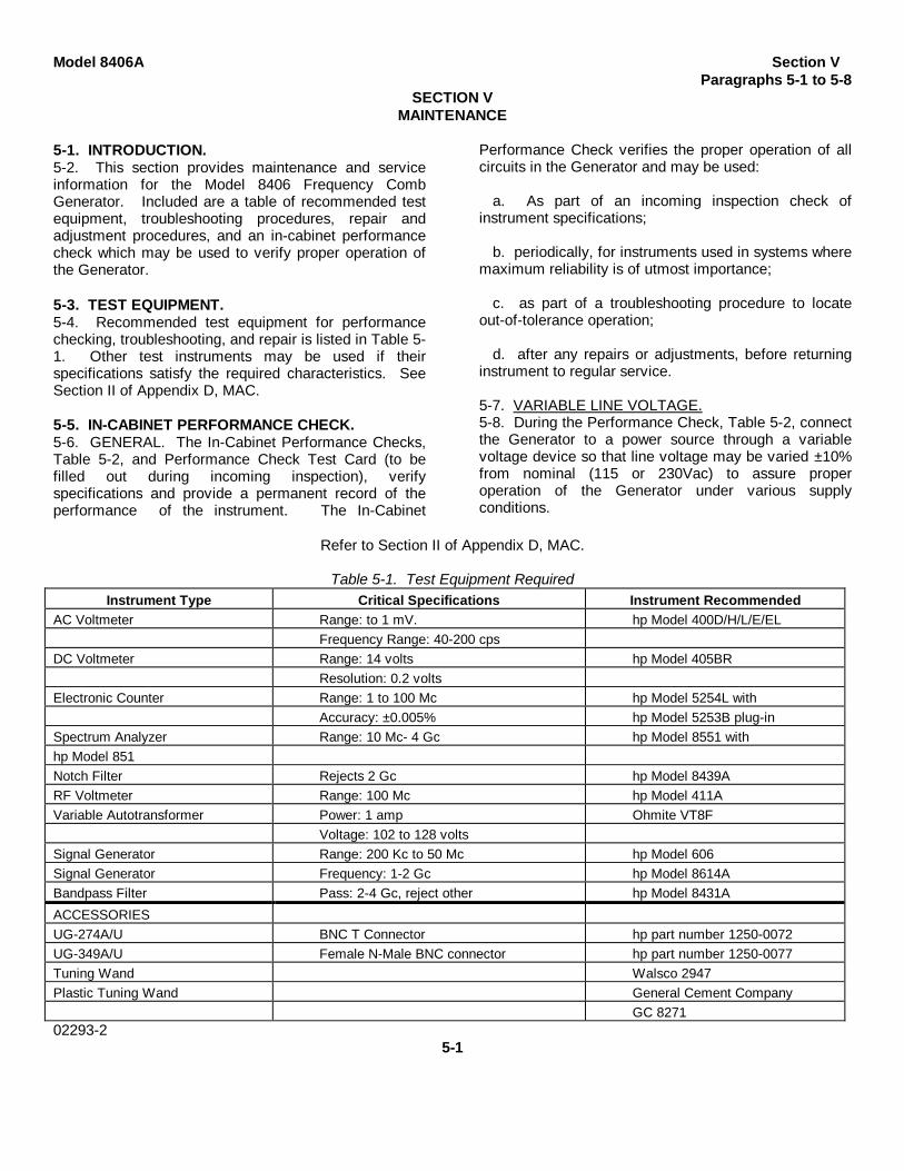
Table 5-1. Test Equipment RequiredInstrument Type Critical Specifications Instrument Recommended
AC Voltmeter Range: to 1 mV. hp Model 400D/H/L/E/ELFrequency Range: 40-200 cps
DC Voltmeter Range: 14 volts hp Model 405BRResolution: 0.2 volts
Electronic Counter Range: 1 to 100 Mc hp Model 5254L withAccuracy: ±0.005% hp Model 5253B plug-in
Spectrum Analyzer Range: 10 Mc- 4 Gc hp Model 8551 withhp Model 851Notch Filter Rejects 2 Gc hp Model 8439ARF Voltmeter Range: 100 Mc hp Model 411AVariable Autotransformer Power: 1 amp Ohmite VT8F
Voltage: 102 to 128 voltsSignal Generator Range: 200 Kc to 50 Mc hp Model 606Signal Generator Frequency: 1-2 Gc hp Model 8614ABandpass Filter Pass: 2-4 Gc, reject other hp Model 8431A
ACCESSORIESUG-274A/U BNC T Connector hp part number 1250-0072UG-349A/U Female N-Male BNC connector hp part number 1250-0077Tuning Wand Walsco 2947Plastic Tuning Wand General Cement Company
GC 827102293-2
5-1
Section V Model 8406ATable 5-2
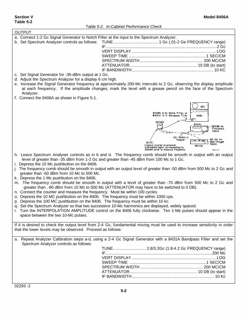
Table 5-2. In-Cabinet Performance CheckOUTPUTa. Connect 1-2 Gc Signal Generator to Notch Filter at the input to the Spectrum Analyzer.b. Set Spectrum Analyzer controls as follows: TUNE.......................................1 Gc (.01-2 Ge FREQUENCY range)
IF ...............................................................................................2 GcVERT DISPLAY .........................................................................LOGSWEEP TIME .. ................................................................1 SEC/CMSPECTRUM WIDTH ...................................................... 200 MC/CMATTENUATOR.......................................................... 10 DB (to start)IF BANDWIDTH...................................................................... 10 KC
c. Set Signal Generator for -35-dBm output at 1 Gc.d. Adjust the Spectrum Analyzer for a display 6 cm high.e. Increase the Signal Generator frequency at approximately 200-Mc intervals to 2 Gc, observing the display amplitude
at each frequency. If the amplitude changes, mark the level with a grease pencil on the face of the SpectrumAnalyzer.
f. Connect the 8406A as shown in Figure 5-1.
h. Leave Spectrum Analyser controls as in b and d. The frequency comb should be smooth in output with an outputlevel of greater than -35 dBm from 1-2 Gc and greater than -45 dBm from 100 Mc to 1 Gc.
i. Depress the 10 Mc pushbutton on the 8406.j. The frequency comb should be smooth in output with an output level of greater than -50 dBm from 500 Mc to 2 Gc and
greater than -60 dBm from 10 Mc to 500 Mc.k. Depress the 1 Mc pushbutton on the 8406.m. The frequency comb should be smooth in output with a level of greater than -70 dBm from 500 Mc to 2 Gc and
greater than .-80 dBm from 10 Mc to 500 Mc (ATTENUATOR may have to be switched to 0 DB).n. Connect the counter and measure the frequency. Must be within 100 cycles.o. Depress the 10 MC pushbutton on the 8406. The frequency must be within 1000 cps.p. Depress the 100 MC pushbutton on the 8406. The frequency must be within 10 kc.q. Set the Spectrum Analyzer so that two successive 10-Mc harmonics are displayed, widely spaced.r. Turn the INTERPOLATION AMPLITUDE control on the 8406 fully clockwise. Ten 1-Me pulses should appear in the
space between the two 10-Mc pulses.
If it is desired to check the output level from 2-4 Gc, fundamental mixing must be used to increase sensitivity in orderthat the lower levels may be observed. Proceed as follows:
a. Repeat Analyzer Calibration steps a-d, using a 2-4 Gc Signal Generator with a 8431A Bandpass Filter and set theSpectrum Analyzer controls as follows:
TUNE............................ 2.8/3.2Gc (1.8-4.2 Gc FREQUENCY range)IF ...........................................................................................200 McVERT DISPLAY .........................................................................LOGSWEEP TIME ..................................................................1 SEC/CMSPECTRUM WIDTH .... ................................................. 200 MC/CMATTENUATOR.......................................................... 10 DB (to start)IF BANDWIDTH....................................................................... 10 Kc
02293 -25-2
Model 8406A Section VParagraphs 5-9 to 5-15
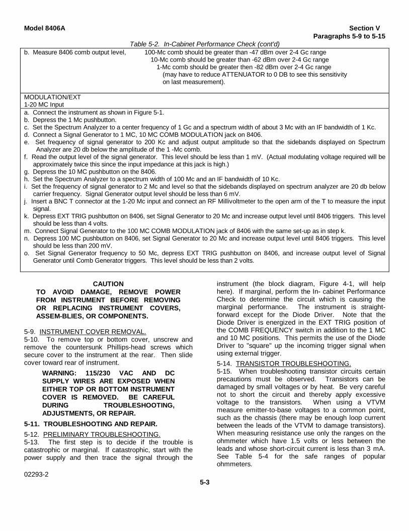
Table 5-2. In-Cabinet Performance Check (cont'd)b. Measure 8406 comb output level, 100-Mc comb should be greater than -47 dBm over 2-4 Gc range
10-Mc comb should be greater than -62 dBm over 2-4 Gc range1-Mc comb should be greater then -82 dBm over 2-4 Gc range
(may have to reduce ATTENUATOR to 0 DB to see this sensitivityon last measurement).
MODULATION/EXT1-20 MC Inputa. Connect the instrument as shown in Figure 5-1.b. Depress the 1 Mc pushbutton.c. Set the Spectrum Analyzer to a center frequency of 1 Gc and a spectrum width of about 3 Mc with an IF bandwidth of 1 Kc.d. Connect a Signal Generator to 1 MC, 10 MC COMB MODULATION jack on 8406.e. Set frequency of signal generator to 200 Kc and adjust output amplitude so that the sidebands displayed on Spectrum
Analyzer are 20 db below the amplitude of the 1 -Mc comb.f. Read the output level of the signal generator. This level should be less than 1 mV. (Actual modulating voltage required will be
approximately twice this since the input impedance at this jack is high.)g. Depress the 10 MC pushbutton on the 8406.h. Set the Spectrum Analyzer to a spectrum width of 100 Mc and an IF bandwidth of 10 Kc.i. Set the frequency of signal generator to 2 Mc and level so that the sidebands displayed on spectrum analyzer are 20 db below
carrier frequency. Signal Generator output level should be less than 6 mV.j. Insert a BNC T connector at the 1-20 Mc input and connect an RF Millivoltmeter to the open arm of the T to measure the input
signal.k. Depress EXT TRIG pushbutton on 8406, set Signal Generator to 20 Mc and increase output level until 8406 triggers. This level
should be less than 4 volts.m. Connect Signal Generator to the 100 MC COMB MODULATION jack of 8406 with the same set-up as in step k.n. Depress 100 MC pushbutton on 8406, set Signal Generator to 20 Mc and increase output level until 8406 triggers. This level
should be less than 200 mV.o. Set Signal Generator frequency to 50 Mc, depress EXT TRIG pushbutton on 8406, and increase output level of Signal
Generator until Comb Generator triggers. This level should be less than 2 volts.
CAUTIONTO AVOID DAMAGE, REMOVE POWERFROM INSTRUMENT BEFORE REMOVINGOR REPLACING INSTRUMENT COVERS,ASSEM-BLIES, OR COMPONENTS.
5-9. INSTRUMENT COVER REMOVAL.5-10. To remove top or bottom cover, unscrew andremove the countersunk Phillips-head screws whichsecure cover to the instrument at the rear. Then slidecover toward rear of instrument.
WARNING: 115/230 VAC AND DCSUPPLY WIRES ARE EXPOSED WHENEITHER TOP OR BOTTOM INSTRUMENTCOVER IS REMOVED. BE CAREFULDURING TROUBLESHOOTING,ADJUSTMENTS, OR REPAIR.
5-11. TROUBLESHOOTING AND REPAIR.5-12. PRELIMINARY TROUBLESHOOTING.5-13. The first step is to decide if the trouble iscatastrophic or marginal. If catastrophic, start with thepower supply and then trace the signal through the
instrument (the block diagram, Figure 4-1, will helphere). If marginal, perform the In- cabinet PerformanceCheck to determine the circuit which is causing themarginal performance. The instrument is straight-forward except for the Diode Driver. Note that theDiode Driver is energized in the EXT TRIG position ofthe COMB FREQUENCY switch in addition to the 1 MCand 10 MC positions. This permits the use of the DiodeDriver to "square" up the incoming trigger signal whenusing external trigger.5-14. TRANSISTOR TROUBLESHOOTING.5-15. When troubleshooting transistor circuits certainprecautions must be observed. Transistors can bedamaged by small voltages or by heat. Be very carefulnot to short the circuit and thereby apply excessivevoltage to the transistors. When using a VTVMmeasure emitter-to-base voltages to a common point,such as the chassis (there may be enough loop currentbetween the leads of the VTVM to damage transistors).When measuring resistance use only the ranges on theohmmeter which have 1.5 volts or less between theleads and whose short-circuit current is less than 3 mA.See Table 5-4 for the safe ranges of popularohmmeters.
02293-25-3

Section V Model 8406AFigure 5-2
Figure 5-2. Location Diagram
02293-15-4

Model 8403 Section VParagraphs 5-16 to 5-18
Table 5-3. Performance Check Test CardDescriptionOutput100 Mc Level deviation ± db
Frequency
10 Mc Level deviation ± dbFrequencyInterpolation frequency
1 Mc Frequency
Modulation/External Trigger 1-20 Mc Input
200 Kc Input level volts2 Mc Input level volts
20 Mc Input level volts2-200 Mc Input
20 Mc Trigger voltage volts
5-16. IN-CIRCUIT TESTING. The most commoncauses of transistor failures are internal short- and open-circuits. In transistor circuit testing the most importantconsideration is the transistor base-emitter junction.Like the control grid of a vacuum tube, the base is thecontrol point of the transistor. The emitter-base voltageshould be a fraction of a volt, the polarity and exactvalue depending upon the material
Table 5-4. Safe Ohmmeter Ranges forTransistor Resistance Measurements
Open Short LeadSafe Ckt Ckt
Ohmmeter Range(s) Voltage Current Color PolarityRx 1K 1.0V 1 maRx 10K 1.0V 100 µa Red +
HP 412A Rx 100K 1.0V 10 µa Black -Rx1M 1.0V 1 µaRx 10M 1.0V 0.1 µaRx 1K 1.3V 0.57 maRx 10K 1.3V 57 µa Red +
HP 410C Rx 100K 1.3V 5.7 µa Black -Rx 1M 1.3V 0.5 µaRx 10M 1.3V 0.05 µaRx 100 1.1V 1.1 µaRx 1K 1.1V 110 µa Black +
HP 410B Rx 10K 1.1V 11 µa RedRx100K 1.1V 1.1 µaRx 1M 1.1V 0.11 µa
Simpson Rx 100 1.5V 1 ma Red +260 Black -
Simpson Rx 1K 1.5V 0.82ma Black +269 Red
Triplett Rx 100 1.5V 3.25 mA Varies with630 Rx 1K 1.5V 325 µA Serial
Triplett Rx 10 1.5V 750 µa Number310 Rx 100 1.5V 75 µa
of the transistor and the current carried. Short theemitter to the base. If the transistor is working, thevoltage on the collector should go toward the supplyvoltage.
5-17. OUT-OF-CIRCUIT TESTING. While it is notrecommended to remove the transistors from theinstrument for troubleshooting as a general rule,sometimes it is impossible to isolate troubles to aparticular transistor. In such case it may be necessaryto remove the suspected transistor and test it on a curvetracer. Do NOT remove a transistor for testing withoutsome indication that this particular transistor is at fault.Use a heat sink, such as a pair of long-nosed pliers,between the soldering iron and the transistor. Whensoldering a transistor back in the circuit use the sameprecautions as when unsoldering. If a particulartransistor is all right but the circuit still does not work, trythe transistor ahead and behind the suspected one.Table 5-5 gives typical resistance measurements oftransistors.
5-18. PRINTED CIRCUIT COMPONENTREPLACEMENT. Component lead holes in the Model8406 circuit board have plated walls to ensure goodelectrical contact between conductors on the oppositesides of the board. To prevent damage to this platingand to the replacement component, apply heat sparinglyand work carefully. The following replacementprocedure is recommended;
a. Remove defective component.b. Melt solder in component lead holes. Use
clean, dry soldering iron to remove excess solder.Clean holes with toothpick or wooden splinter. Do notuse metal tool for cleaning as this may damage through-hole plating.
Table 5-5. Output-of-Circuit TransistorResistance Measurement
Connect Ohmmeter MeasureTransistor Pos. Neg. Resistance
Type lead to lead to (ohms)Small emitter base* 200-500
PNP Signal emitter collector 10K-100KGer-
manium emitter base* 30-50Power several
emitter collector hundredSmall base emitter 1K-3KSignal collector emitter very high
NPN (might readopen)
Silicon base emitter 200-1000high, often
Power collector emitter greater than1M
*To test for transistor action, add collector-base short. Measuredresistance should decrease.
02293-2
5-5

Section V Model 8406AParagraphs 5-19 to 5-22
c. Bend lead of replacement component tocorrect shape and insert component leads into leadholes. Using heat and solder sparingly, solder leads inplace. Heat may be applied to either side of the board.Use heat sink (long-nose pliers, commercial heat-sinktweezers, etc.) when replacing transistors and diodes inorder to prevent conduction of excessive heat from thesoldering iron to the component. Firm application ofheat for the shortest possible time is the rule.
d. Through-hole plating breaks are indicated bythe separation from the board of the round conductorpad on either side of the board. To repair breaks, pressconductor pads against board and solder replacementcomponent lead to conductor pad on both sides of theboard.5-19. ADJUSTMENTS.5-20. Rarely, if ever, will it be necessary to performadjustments on a particular instrument. Do NOTperform these adjustments as a performance check.Use the performance check. Test limits given hereshould not be construed as part of the specifications.5-21. POWER SUPPLY. Perform the following tests ateither 115 or 230 volt 50-400 cps, unless otherwisenoted. When line voltage variations are specified, thetest limits apply at the following voltages:
115 VOLTS 230 VOLTSLow line 103 volts 207 voltsNormal line 115 volts 230 voltsHigh line 127 volts 253 volts
Proceed as follows:a. Depress 10 MC COMB FREQUENCY
pushbutton.b. Set INTERPOLATION AMPLITUDE fully
clockwise.
c. Set OUTPUT AMPLITUDE fully clockwise.d. Connect a dc and an ac voltmeter to the -14
volt supply. This is a violet wire on top of the printedcircuit, third terminal from the rear (see Figure 5-2 forlocation).
e. Vary the line voltage from low to high whilewatching the meters. The dc voltage should stay inregulation within 0.5Vdc and the ac voltage (ripple)should be below 3 millivolts.5-22. OSCILLATOR FREQUENCIES. Connect theinstrument as shown in Figure 5-1. The 2 Gc NotchFilter prevents overloading of 851/8551 SpectrumAnalyzer at the intermediate frequency, but may not benecessary with all Spectrum Analyzers. Set Generatorcontrols as follows:
COMB FREQUENCY ............................ 100 MCINTERPOLATION AMPLITUDE ..................OFFOUTPUT AMPLITUDE ................ fully clockwise
a. Set Spectrum Analyzer to a center frequencyof 1 Gc with spectrum width of 2 Gc. The frequencycomb should be smooth in output. If not, tune A1T1(see location diagram, Figure 5-2) with a Walsco 2547tuning wand for a stable frequency and A1T2 formaximum flat output in the 400-Mc region as theOUTPUT AMPLITUDE control is varied from maximumto minimum.
b. Connect counter and tune A1C39 (see locationdiagram, Figure 5-2) for 100-Mc frequency.
c. Depress 10 Mc pushbutton and use counter tomeasure frequency. Tune A1C18 with a GeneralCement 8271 plastic tuning wand to 10 Mc.
d. Depress 1 Mc pushbutton and use counter tomeasure frequency. Tune A1C7 to 1 Mc.
02293 -2
5-6

Model 8406A Section VIParagraphs 6-1 to 6-7
SECTION VIREPLACEABLE PARTS
See Table 6-4, PART NUMBER-NATIONAL STOCK NUMBER CROSS-REFERENCE INDEX.
6-1. INTRODUCTION.6-2. This section contains information aboutreplacement parts. Table 6-1 lists parts inalphanumerical order of their reference designators andindicates the description and hp stock number of eachpart, together with any applicable notes. Table 6-2 listsparts in alpha-numerical order of their hp stock numbersand provides the following information on each part:
a. Description of the part (see list of abbreviationsbelow).
b. Typical manufacturer of the part in a five-digitcode; see list of manufacturers in Table 6-3.
c. Manufacturer's stock number.d. Total quantity used in the instrument (TQ
column).6-3. Miscellaneous parts not indexed in Table 6-1 arelisted at the end of the table.6-4. DELETED
REFERENCE DESIGNATORSA = assembly F = fuse MP = mechanical part V = vacuum, tube, neonB = motor FL = filter P = plug bulb, photocell, etc.BT = battery IC = integrated circuit Q = transistor VR = voltage regulatorC = capacitor J = jack R = resistor W = cableCP = coupler K = relay RT = thermistor X = socketCR = diode L = inductor S = switch Y = crystalDL = delay line LS = loud speaker T = transformer Z = tuned cavity,DS = device signaling (lamp) M = meter TB = terminal board networkE = misc electronic part MK = microphone TP = test point
ABBREVIATIONSA = amperes H = henries N/O = normally open RMO = rack mount onlyAFC = automatic frequency control HDW = hardware NPO = negative positive zero RMS = root-mean squareAMPL = amplifier HEX = hexagonal (zero temperature RWV = reverse working
HG = mercury coefficient) voltageBFO = beat frequency oscillator HR = hour(s) NPN = negative-positive- S-B = slow-blowBE CU = beryllium copper HZ = hertz negative SCR = screwBH = binder head NRFR = not recommended for SE = seleniumBP = bandpass IF = intermediate freq field replacement SECT = section(s)BRS = brass IMPG = impregnated NSR = not separately SEMICON = semiconductorBWO = backward wave oscillator INCD = incandescent replaceable SI = silicon
INCL = include(s)CCW = counter-clockwise INS = insulation(ed) SIL = silverCER = ceramic INT = internal OH = oval head SL = slideCMO = cabinet mount only SPG = springCOEF = coefficient K = kilo OX = oxide SPL = specialCOM = common SST = stainless steelCOMP = composition LH = left hand P = peak SR = split ringCOMPL = complete LIN = linear taper PC = printed circuit STL = steelCONN = connector LK WASH = lock washer PF = picofarads = 10-12
CP = cadmium plate LOG = logarithmic taper farads TA tantalumCRT = cathode-ray tube LPF = low pass filter PH BRZ = phosphor bronze TD = time delayCW = clockwise PHL = Phillips TGL = toggle
M = milli = 10-3 PIV = peak inverse voltage THD = threadDEPC = deposited carbon MEG = meg = 106 PNP = positive-negative- TI = titaniumDR = drive MET FLM = metal film positive TOL = tolerance
MET OX = metallic oxide P/O = part of TRIM = trimmerELECT = electrolytic MFR = manufacturer POLY = polystyrene TWT = traveling wave tubeENCAP = encapsulated MHZ = mega hertz PORC = porcelainEXT = external MINAT = miniature POS = position(s) U = micro = 10-6
F = farads MOM = momentary POT = potentiometer VAR = variableFH = flat head MTG = mounting PP = peak-to-peak VDCW = dc working voltsFIL H = fillister head MY = "mylar" PT = point W/ = withFXD = fixed PWV = peak working voltage W = wattsG = giga (109) N = nano (10-9) RECT = rectifier WIV = working inverseGE = germanium N/C = normally closed RF = radio frequency voltageGL = glass NE = neon RH = round head or WW = wirewoundGRD = ground(ed) NI PL = nickel plate right hand W/O = without01194-1302293-1
6-1

Section VI Model 8406ATable 6-1
Table 6-1. Reference Designation IndexReference
Designation hp Stock No. Description # NoteA1 08406-6001 BOARD ASSY., ETCHED CIRCUIT
A1C1 0160-0174 C:FXD CER 0.47UF +80-20% 25VDCWA1C2 0160-0127 C:FXD CER 1WF 20% 25VDCWA1C3 0160-0134 C:FXD MICA 220PF 5% 300VDCWA1C4 0160-0194 C:FXD MY 0.01SUF 10%A1C5 0150-0050 C:FXD CER 1000PF 600 VDCW
A1C6 0140-0145 C:FXD MICA 22 PF 5% 500 VDCWA1C7 0121-0127 C:VAR A1R 1.7-14PFA1CS 0150-0121 C:FXD CER 0.1UF +80X-20% 50VDCWA1C9 0150-0093 C:FXD CER 0.01UF +80-20% 100VDCWA1C10 0140-0192 C:FXD MICA 68PF 5% 300VDCW
A1C11 0160-0179 C:FXD MICA 33PF 5% 300VDCWA1C12 0140-0192 C:FXD MICA 68PF 5% 300VDCWA1C13 0150-0096 C:FXD CER 0.05UF 100VDCWA1C14 0150-0121 C:FXD CER 0.1LUF +80%-20% 50VDCWA1C15 0140-0204 C:FXD MICA 47PF 5% NPO 500VDCW
A1C16 0140-0232 C:FXD MICA 460PF 1% 300VDCWA1C17 0160-0178 C:FXD MICA 27PF 5% 300VDCWA1C18 0121-0127 C:VAR A1R 1.7-14PFA1C19 0140-0176 C:FXD MICA 100 PF 2% 300 VDCWA1C20 0150-0050 C:FXD CER 1000PF 600 VDCW
A1C21 0140-0204 C:FXD MICA 47PF 5% NPO 500VDCWA1C22 0150-0093 C:FXD CER 0.01UF +80-20% 100VDCWA1C23 0150-0121 C:FXD CER 0.1UF +80%-20% 50VDCWA1C24 0160-0340 C:FXD MICA 600 PF 1% 300VDCWA1C25 0150-0050 C:FXD CER 1000PF 600 VDCW
A1C26 0180-0119 C:FXD ELECT 1UF -10+100% 25VODCA1C27 0150-0050 C:FXD CER 1000PF 600 VDCWA1C28 0140-0209 C:FXD MICA 5PF 10% 500VDCWA1C29 0160-2197 C:FXD MICA 10PF 5%A1C30 0150-0050 C:FXD CER 1000PF 600 VDCW
A1C31 0150-0050 C:FXD CER 1000PF 600 VDCWA1C32 0140-0209 C:FXD MICA 5PF 10% 50OVDCWA1C33 0140-0232 C:FXD MICA 460PF 1% 300VDCWA1C34 0150-0050 C:FXD CER 100PF 600 VDCWA1C35 0180-0138 C:FXD ELECT 100UF -10+100% 40VDCW
A1C36 0180-0059 C:FXD ELECT 10UF -10%+100% 25VDCWA1C37 0180-0059 C:FXD ELECT 10UF -10%+100% 25VDCWA1C38 0180-0059 C:FXD ELECT 10UF -10%+100% 25VDCWA1C39 0121-0127 C:VAR A1R 1.7-14PFA1C40 0150-0050 C:FXD CER 1000PF 600 VDCWA1C41 0160-2140 C:FXD CER 470 PF +80-2Y¼ 1000VDCWA1CR1 1901-0040 DIODE:SILICON 30 MA AT IV 30 PIVA1CR2 1912-0007 DIODE:TUNNEL EIA TYPE 1N3714A1CR3 1901-0026 DIODE:SILICON 200 PIV 0.5 AMPA1CR4 1901-0026 DIODE:SILICON 200 PIV 0.5 AMPA1CR5 1901-0025 DIODE:JUNCTION:5MA AT IV 100 PIV
A1CR6 1901-0025 DIODE:JUNCTION:5MA AT IV 100 PIVA1CR7 1901-0025 DIODE:JUNCTION:5MA AT IV 100 PIV
A1L1 9140-0131 COIL:FXD RF 10 MH
# See list of abbreviations in introduction to this section02293-2
6-2

Section VI Model 8406ATable 6-1
Table 6-1. Reference Designation Index (Cont'd)Reference
Designation hp Stock No. Description # Note
A1L2 9140-0131 COIL:FXD RF 10 MHA1L3 9140-0131 COIL:FXD RF 10 MHA1L4 9140-0181 COIL:FXD RF 22UH 5%A1L5 9140-0210 COIL:FXD RF 100 UH 5%A1L6 9140-0210 COIL:FXD RF 100 UH 5%
A1L7 9140-0210 COIL:FXD RF 100 UH 5%A1LS 9140-0158 COIL:FXD 1.0UH 10%A1L9 9100-1612 COIL:FXD RF 0.33 UH 20%A1L10 9140-0210 COIL:FXD RF 100 UH 5%A1L11 9100-1613 COIL:FXD RF 0.47 UH 20%
A1Q1 1854-0005 TRANSISTOR:2N708 NPN SILICONA1Q2 1854-0005 TRANSISTOR:2N708 NPN SILICONA1Q3 1850-0099 TRANSISTOR:GERMANIUM 2N964 PNPA1Q4 1854-0019 TRANSISTOR:SILICON NPNA1Q5 1854-0073 TRANSISTOR:SILICON NPN 2N3478
A1Q6 1850-0062 TRANSISTOR:GERMANIUM PNP 2N404A1Q7 1854-0073 TRANSISTOR:SILICON NPN 2N3478A1Q8 1850-0062 TRANSISTOR:GERMANIUM PNP 2N404A1Q9 1850-0064 TRANSISTOR:GERMANIUM PNP 2N1183
A1R1 0698-3156 R:FXD MET FLM 14.7K OHM 1% 1/8WA1R2 0757-0439 R:FXD MET FLM 6.81K OHM 1% 1/8WA1R3 0698-0082 R:FXD MET FLM 464 OHM 1% 1/8WA1R4 0698-3441 R:FXD MET FLM 215 OHM 1% 1/8WA1RS 0698-0083 R:FXD MET FLM 1960 OHM 1% 1/8W
A1R6 0757-0465 R:FXD MET FLM 100K OHM 1% 1/8WA1R7 0698-0082 R:FXD MET FLM 464 OHM 1% 1/8WA1R8 0757-0280 R:FXD MET FLM 1.00K OHM 1% 1/8WA1R9 0698-3136 R:FXD MET FLM 17.8K OHM 1% 1/8WA1R10 07?57-0439 R:FXD MET FLM 6.81K OHM 1% 1/8W
A1R1L 0698-0082 R:FXD MET FLM 464 OHM 1% 1/8WA1R12 0698-3441 R:FXD MET FLM 215 OHM 1% 1/8WA1R13 0698-0084 R:FXD MET FLM 2150 OHM 1% 1/8WA1R14 0698-0084 R:FXD MET FLM 2150 OHM 1% 1/8WA1R15 0757-0280 R:FXD MET FLM 1.00K OHM 1% 1/8W
A1R16 0757-1094 R:FXD MET FLM 1.47K OHM 1% 1/8WA1R17 0757-0401 R:FXD MET FLM 100 OHM 1% 1/8WA1R18 0698-3441 R:FXD MET FLM 215 OHM 1% 1/8W*A1R19 0757-0401 R:FXD MET FLM 100 OHM 1% 1/8WA1R20 0757-0441 R:FXD MET FLM 8.25K OHM 1% 1/8W
A1R21 0698-3154 R:FXD MET FLM 4220 OHM 1% 1/8A1R22 0757-0417 R:FXD MET FLM 562 OHM 1% 1/8WA1R23 0698-3440 R:FXD MET FLM 196 OHM 15 1/8WA1R24 0698-3441 R:FXD MET FLM 215 OHM 1% 1/8WA1R25 0698-3430 R:FXD MET FLM 21.5 OHM 1% 1/8W
A1R26 0698-3430 R:FXD MET FLM 21.5 OHM 1% 1/8WA1R27 0757-0346 R:FXD MET FLM 10.0 OHM 1% 1/8WA1R28 0698-0084 R:FXD MET FLM 2150 OHM 1% 1/8WA1R29 0698-0084 R:FXD MET FLM 2150 OHM 1% 1/8WA1R30 0757-0346 R:FXD MET FLM 10,0 OHM 1% 1/81A1R31 0698-3445 R:FXD MET FLM 348 OHM 1% 1/8WA1R32 0757-0416 R:FXD MET FLM 511 OHM 1% 1/8W
A1T1 08406-6013 TRANSFORMER:RF(OSCILLATOR)
# See list of abbreviations in introduction to this section02293-2
6-3

Section VI Model 8406ATable 6-1
Table 6-1. Reference Designation IndexReference
Designation hp Stock No. Description # Note
A1T2 08406-6014 TRANSFORMER:RF(AMPLIFIER)
A1VR1 1902-0055 DIODE BREAKDOWN:SILICON 14.7V 10%
A1XY1 1200-0028 SOCKET:CRYSTAL 2-CONTACT
A1Y1 .0410-0013 CRYSTAL UNIT:QUARTZ 1000KCA1Y2 0410-0109 CRYSTAL:QUARTZ 10 MCA1Y3 0410-0108 CRYSTAL:QUARTZ 100 MC
5000-0011 CLIP:ELECTRICAL RETAINING
C1 0150-0097 C:FXD CER 6800 PF 1000 VDCWC2 0150-0019 C:FXD CER 1000PF 20%C3 0150-0019- C:FXD CER 1000PF 20%C4 0150-0097 C:FXD CER 6800 PF 1000 VDCW
CR1 08406-6002 HOLDER ASSEMBLY, DIODE INCLUDES:1901-0169 SEMICON DEVICE:DIODE08551-2041 POST: DIODE1150-0014 CONTACT:OUTER N MALE CONNECTOR1250-0016 RING:LOCKING FOR TYPE N CONNECTOR
5020-0306 NUT:CONNECTOR08406-2002 BODY: DIODE HOLDER08406-2003 CENTER CONDUCTOR
DS1 2140-0047 LAMP:GLOW 1/10W 0.8 MA 68K OHM
F1 2110-0040 FUSE:CARTRIDGE 1/16 AMP SLOW BLOW
J1 1250-0001 CONNECTOR:BNCJ2 1250-0001 CONNECTOR:BNCJ3 1251-0148 CONNECTOR:POWER 3 PIN MALEJ4 NSR PART OF STEP DIODE ASSY.J5 08406-2004 CONNECTOR: PANEL
L1 9170-0019 CORE:TOROIDL2 9170-0019 CORE:TOROID
P1 NSR PART OF ATTENUATOR ASSY
R1 2100-0350 R:VAR COMP 1.SK OHM 20% LIN 1/2WR2 0687-6831 R:FXD COMP 68K OHM 10% 1/2WR3 2100-0350 R:VAR COMP 1500 OHM 20 LIN 1/2W
S1 5101-0186 SWITCH:PUSHBUTTON(FREQUENCY)S2 5101-0033 SWITCH:SLIDE DPDT
115V-230VS3 NOT ASSIGNEDS4 NSR PART OF R3
T1 9100-1680 TRANSFORMER:POWER
XF1 1400-0084 HOLDER:FUSE POST TYPE 3AG
Z1 08406-6012 ATTENUATOR PAD ASSEMBLY INCLUDES:1460-0297 SPRING:COMPRESSION08491-6000 CARTRIDGE ASSEMBLY08491-2101 CONNECTOR:FEMALE08491-2102 Spacer, 2 ea.
# See list of abbreviations in introduction to this section02293-2
6-4

Model 8406A Section VITable 6-1
Table 6-1. Reference Designation Index (Cont'd)Reference
Designation hp Stock No. Description # Note
08742-0006 SPACER08491-2002 BEAD06491-4001 PIN, FEMALE08491-2009 CONTACT, SLIDING
MISCELLANEOUS
08406-0003 BRACKET, BOTTOM COVER08406-0004 BRACKET, RIGHT SUPPORT08406-0005 BRACKET, LEFT SUPPORT08406-0006 BRACKET, SWITCH08406-6004 CABLE ASSY., COAX(ORANGE)
08406-6005 CABLE ASSY., COAX(RED)08406-6006 CABLE ASSY., COAX(BROWN))08406-6007 CABLE ASSY., COAX(BLACK))08406-6009 CABLE ASSY., COAX(YELLOW)08406-6010 CABLE ASSY., COAX(GREEN)
08406-6011 CABLE ASSY., COAX(BLUE)8120-0078 CABLE ASSY:POWER5040-0235 BASE:LAMPHOLDER5040-0234 LAMPHOLDER0370-0118 KNOB:GRAY PUSHBUTTON 11/16 IN DIA
1MC10MC100MCEXT TRIG
5000-3227 LABEL:PUSHBUTTON (1 MC)5000-3228 LABEL:PUSHBUTTON(10 MC)5000-3229 LABEL:PUSHBUTTON(100 MC)5000-3248 LABEL:PUSHBUTTON(EXT. TRIG)08406-0001 SUPPORT, LEFT
08406-0002 SUPPORT, RIGHT
0370-0103 KNOB:BLACK ROUNDOUTPUT AMPLITUDEINTERPOLATION AMPLITUDE 1MC
# See list of abbreviations in introduction to this section
02293-26-5

Section VI Model 8406ATable 6-1
Table 6-1. Reference Designation Index (Cont'd)Reference
Designation hp Stock No. Description # Note
MODULESIZE 29
CABINET PARTS
1 5060-0703 FRAME ASSEMBLY2 1490-0031 STAND: TILT3 5040-0700 HINGE4 5060-0727 FOOT ASSEMBLY'5 5020-0700 SPACER
6 5000-0703 COVER:SIDE7 5060-0709 COVER ASSEMBLY TOP
UNPERFORATED FULL RECESS5060-0706 UNPERFORATED HALF RECESS5060-0715 PERFORATED FULL RECESS5060-0712 PERFORATED HALF RECESS
8 5000-0711 COVER ASSEMBLY:BOTTOMUNPERFORATED
5000-0714 PERFORATED
9 SEE MAT'L. LIST PANEL:REAR10 SEE MAT'L.. LIST PANEL:FRONT
# See list of abbreviations in introduction to this section02293-2
6-6

Model 8406A Section VITable 6-2
Table 6-2. Replaceable Parts (Cont'd)hp Stock No. Description# Mfr. Mfr. Part No. TQ
0121-0127 C:VAR AIR 1.7-14PF 28480 0121-0127 30140-0145 C:FXD MICA 22 PF 5% 500 VDCW 04062 RDM15C220J5C 10140-0176 C:FXD MICA 100 PF 2% 300 VDCW 04062 RDM15F101G3C 10140-0192 C:FXD MICA 68PF 5% 300VDCW 04062 RDM15E680J3C 20140-0204 C:FXD MICA 47PF 5% NPO 500VDCW 04062 RDM15E470J5C 2
0140-0209 C:FXD MICA 5PF 10% 50OVDCW 04062 RDM15C050D5C 20140-0232 C:FXD MICA 460PF 1% 300VDCW 04062 RDM15F461F3C 20150-0019 C:FXD CER 1000PF 20% 72982 327005XUL0102M 20150-0050 C:FXD CER 1000PF 600 VDCW 84411 TYPE E 80150-0093 C:FXD CER 0.01UF +80-20% 100VDCW 91418 TA 2
0150-0096 C:FXD CER 0.05UF 100VDCW 91418 -TA 10150-0097 C:FXD CER 6800 PF 1000 VDCW 91418 B 20150-0121 C:FXD CER 0.1UF +80%-20% 50VDCW 56289 5050A 30160-0127 C:FXD CER 1UF 204 25VDCW 56289 5013 10160-0134 C:FXD MICA 220PF 5% 300VDCW 14655 RDM15F221J3C 1
0160-0174 C:FXD CER 0.47UF +80-20% 25VDCW 56289 5C11A 10160-0178 C:FXD MICA 27PF 5% 300VDCW 04062 RDM15E270J3S 10160-0179 C:FXD MICA 33PF 5% 300VDCW 04062 ROM15E330J3S 10160-0194 C:FXD MY 0.015UF 10% 28480 0160-0194 10160-0340 C:FXD MICA 600 PF 1% 300VDCW 04062 RDM15F601F3C 10160-2140 C:FXD CER 470 PF +80-20% 1000VDCW 91418 TYPE B 10160-2197 C:FXD MICA 10PF 5% 28480 0160-2197 10180-0059 C:FXD ELECT 10UF -10%+100% 25VDCW 56289 30D106G025BB4 50180-0119 C:FXD ELECT 1UF -10+100% 25VDCW 56289 30D105G025AA4 10180-0138 C:FXD ELECT 100UF -10+100% 40VDCW 56289 036254 10570-0103 KNOB:BLACK ROUND 28480 0370-0103 20370-0118 KNOB:GRAY PUSHBUTTON 11/16" DIA 28480 0370-0118 40410-0013 CRYSTAL UNIT:QUARTZ 1000KC 28480 0410-0013 10410-0108 CRYSTAL:QUARTZ 100 MC 28480 0410-0108 10410-0109 CRYSTAL:QUARTZ 10 MC 28480 0410-0109 10687-68351 R:FXD COMP 68K OHM 10% 1/2W 01121 EB-6831 10698-0082 R:FXD MET FLM 464 OHM 1% 1/8W 28480 0698-0082 30698-0083 R:FXD MET FLM 1960 OHM 1% 1/8W 28480 0698-0083 10698-0084 R:FXD MET FLM 2150 OHM 1% 1/8W 28480 0698-0084 40698-3136 R:FXD MET FLM 17.8KOHM 1% 1/8W 28480 0698-3136 10698-3154 R:FXD MET FLM 4220 OHM 1% 1/8W 28480 0698-3154 10698-3156 R:FXD MET FLM 14.7KOHM 1% 1/8W 28480 0698-3156 10698-3430 R:FXD MET FLM 21.5 OHM 1% 1/8W 28480 0698-5430 20698-3440 R:FXD MET FLM 196 OHM 1% 1/8W 28480 0698-3440 10698-3441 R:FXD MET FLM 215 OHM 1% 1/8W 28480 0698-3441 40698-3445 R:FXD MET FLM 348 OHM 1% 1/8W 28480 0698-3445 10757-0280 R:FXD MET FLM 1.0KOHM 1% 1/8W 28480 0757-0280 20757-0346 R:FXD MET FLM 10.0 OHM 1% 1/8W 28480 0757-0346 20757-0LwUo R:FXD MET FLM 100 OHM 1% 1/8W 28480 0757-0401 20757-0416 R:FXD MET FLM 511 OHM 1% 1/8W 28480 0757-0416 10757- 0417 R:FXD MET FLM 562 OHM 1% 1/8W 28480 0757-0417 10757- 0439 R:FXD MET FLM 6.81K OHM 1% 1/8W 28480 0757-0439 20757-0441 R:FXD MET FLM 8.25KOHM 1% 1/8W 28480 0757-0441 10757-1094 R:FXD MET FLM 1.47K OHM 1% 1/8W 28480 0757-1094 11200-0028 SOCKET:CRYSTAL 2-CONTACT 91662 430 BC 1
1250-0014 CONTACT:OUTER N MALE CONNECTOR 28480 1250-0014 11250-0016 RING:LOCKING FOR TYPE N CONNECTOR 28480 1250-0016 11250-0001 CONNECTOR:BNC 28480 1250-0001 21251-0148 CONNECTOR:POWER 3 PIN MALE 60427 H-1061-2 11400-0064 HOLDER:FUSE POST TYPE 3AG 75915 342014 1
# See list of abbreviations in introduction to this section02293-2
6-7
Section VI Model 8406ATable 6-2
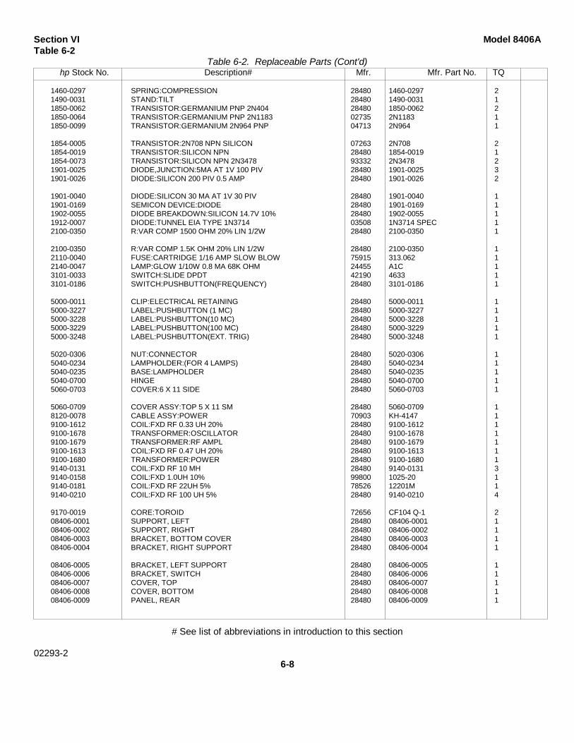
Table 6-2. Replaceable Parts (Cont'd)hp Stock No. Description# Mfr. Mfr. Part No. TQ
1460-0297 SPRING:COMPRESSION 28480 1460-0297 21490-0031 STAND:TILT 28480 1490-0031 11850-0062 TRANSISTOR:GERMANIUM PNP 2N404 28480 1850-0062 21850-0064 TRANSISTOR:GERMANIUM PNP 2N1183 02735 2N1183 11850-0099 TRANSISTOR:GERMANIUM 2N964 PNP 04713 2N964 1
1854-0005 TRANSISTOR:2N708 NPN SILICON 07263 2N708 21854-0019 TRANSISTOR:SILICON NPN 28480 1854-0019 11854-0073 TRANSISTOR:SILICON NPN 2N3478 93332 2N3478 21901-0025 DIODE,JUNCTION:5MA AT 1V 100 PIV 28480 1901-0025 31901-0026 DIODE:SILICON 200 PIV 0.5 AMP 28480 1901-0026 2
1901-0040 DIODE:SILICON 30 MA AT 1V 30 PIV 28480 1901-0040 11901-0169 SEMICON DEVICE:DIODE 28480 1901-0169 11902-0055 DIODE BREAKDOWN:SILICON 14.7V 10% 28480 1902-0055 11912-0007 DIODE:TUNNEL EIA TYPE 1N3714 03508 1N3714 SPEC 12100-0350 R:VAR COMP 1500 OHM 20% LIN 1/2W 28480 2100-0350 1
2100-0350 R:VAR COMP 1.5K OHM 20% LIN 1/2W 28480 2100-0350 12110-0040 FUSE:CARTRIDGE 1/16 AMP SLOW BLOW 75915 313.062 12140-0047 LAMP:GLOW 1/10W 0.8 MA 68K OHM 24455 A1C 13101-0033 SWITCH:SLIDE DPDT 42190 4633 13101-0186 SWITCH:PUSHBUTTON(FREQUENCY) 28480 3101-0186 1
5000-0011 CLIP:ELECTRICAL RETAINING 28480 5000-0011 15000-3227 LABEL:PUSHBUTTON (1 MC) 28480 5000-3227 15000-3228 LABEL:PUSHBUTTON(10 MC) 28480 5000-3228 15000-3229 LABEL:PUSHBUTTON(100 MC) 28480 5000-3229 15000-3248 LABEL:PUSHBUTTON(EXT. TRIG) 28480 5000-3248 1
5020-0306 NUT:CONNECTOR 28480 5020-0306 15040-0234 LAMPHOLDER:(FOR 4 LAMPS) 28480 5040-0234 15040-0235 BASE:LAMPHOLDER 28480 5040-0235 15040-0700 HINGE 28480 5040-0700 15060-0703 COVER:6 X 11 SIDE 28480 5060-0703 1
5060-0709 COVER ASSY:TOP 5 X 11 SM 28480 5060-0709 18120-0078 CABLE ASSY:POWER 70903 KH-4147 19100-1612 COIL:FXD RF 0.33 UH 20% 28480 9100-1612 19100-1678 TRANSFORMER:OSCILLATOR 28480 9100-1678 19100-1679 TRANSFORMER:RF AMPL 28480 9100-1679 19100-1613 COIL:FXD RF 0.47 UH 20% 28480 9100-1613 19100-1680 TRANSFORMER:POWER 28480 9100-1680 19140-0131 COIL:FXD RF 10 MH 28480 9140-0131 39140-0158 COIL:FXD 1.0UH 10% 99800 1025-20 19140-0181 COIL:FXD RF 22UH 5% 78526 12201M 19140-0210 COIL:FXD RF 100 UH 5% 28480 9140-0210 4
9170-0019 CORE:TOROID 72656 CF104 Q-1 208406-0001 SUPPORT, LEFT 28480 08406-0001 108406-0002 SUPPORT, RIGHT 28480 08406-0002 108406-0003 BRACKET, BOTTOM COVER 28480 08406-0003 108406-0004 BRACKET, RIGHT SUPPORT 28480 08406-0004 1
08406-0005 BRACKET, LEFT SUPPORT 28480 08406-0005 108406-0006 BRACKET, SWITCH 28480 08406-0006 108406-0007 COVER, TOP 28480 08406-0007 108406-0008 COVER, BOTTOM 28480 08406-0008 108406-0009 PANEL, REAR 28480 08406-0009 1
# See list of abbreviations in introduction to this section
02293-26-8
Model 8406A Section VITable 6-2
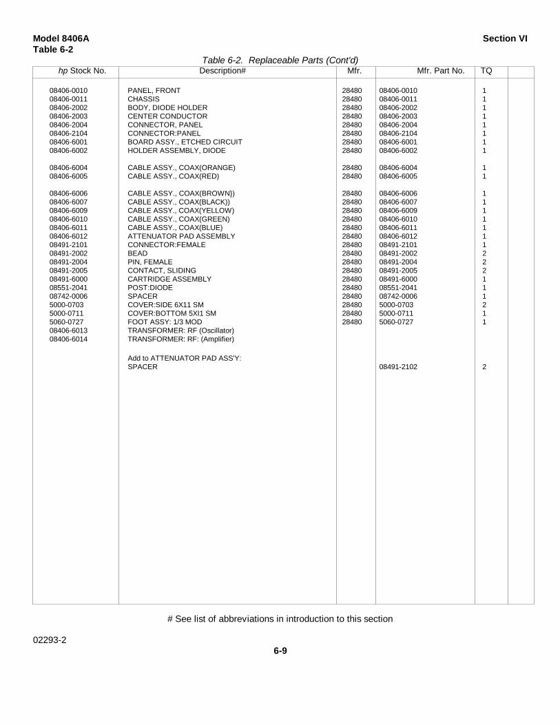
Table 6-2. Replaceable Parts (Cont'd)hp Stock No. Description# Mfr. Mfr. Part No. TQ
08406-0010 PANEL, FRONT 28480 08406-0010 108406-0011 CHASSIS 28480 08406-0011 108406-2002 BODY, DIODE HOLDER 28480 08406-2002 108406-2003 CENTER CONDUCTOR 28480 08406-2003 108406-2004 CONNECTOR, PANEL 28480 08406-2004 108406-2104 CONNECTOR:PANEL 28480 08406-2104 108406-6001 BOARD ASSY., ETCHED CIRCUIT 28480 08406-6001 108406-6002 HOLDER ASSEMBLY, DIODE 28480 08406-6002 1
08406-6004 CABLE ASSY., COAX(ORANGE) 28480 08406-6004 108406-6005 CABLE ASSY., COAX(RED) 28480 08406-6005 1
08406-6006 CABLE ASSY., COAX(BROWN}) 28480 08406-6006 108406-6007 CABLE ASSY., COAX(BLACK)) 28480 08406-6007 108406-6009 CABLE ASSY., COAX(YELLOW) 28480 08406-6009 108406-6010 CABLE ASSY., COAX(GREEN) 28480 08406-6010 108406-6011 CABLE ASSY., COAX(BLUE) 28480 08406-6011 108406-6012 ATTENUATOR PAD ASSEMBLY 28480 08406-6012 108491-2101 CONNECTOR:FEMALE 28480 08491-2101 108491-2002 BEAD 28480 08491-2002 208491-2004 PIN, FEMALE 28480 08491-2004 208491-2005 CONTACT, SLIDING 28480 08491-2005 208491-6000 CARTRIDGE ASSEMBLY 28480 08491-6000 108551-2041 POST:DIODE 28480 08551-2041 108742-0006 SPACER 28480 08742-0006 15000-0703 COVER:SIDE 6X11 SM 28480 5000-0703 25000-0711 COVER:BOTTOM 5XI1 SM 28480 5000-0711 15060-0727 FOOT ASSY: 1/3 MOD 28480 5060-0727 108406-6013 TRANSFORMER: RF (Oscillator)08406-6014 TRANSFORMER: RF: (Amplifier)
Add to ATTENUATOR PAD ASS'Y:SPACER 08491-2102 2
# See list of abbreviations in introduction to this section
02293-26-9

Section VI Model 8406ATable 6-3
TABLE 6-3.CODE LIST OF MANUFACTURERS
6-10

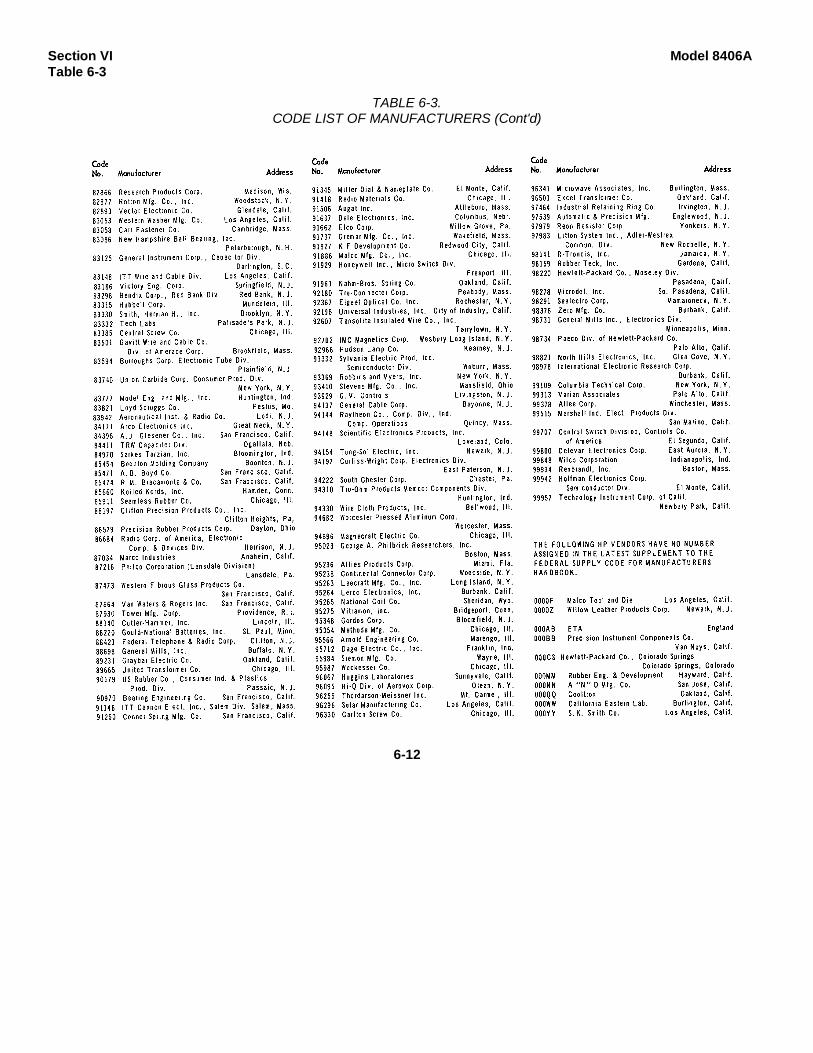
Model 8406A Section VITable 6-3
TABLE 6-3.CODE LIST OF MANUFACTURERS (Cont'd)
6-11
Section VI Model 8406ATable 6-3
TABLE 6-3.CODE LIST OF MANUFACTURERS (Cont'd)
6-12
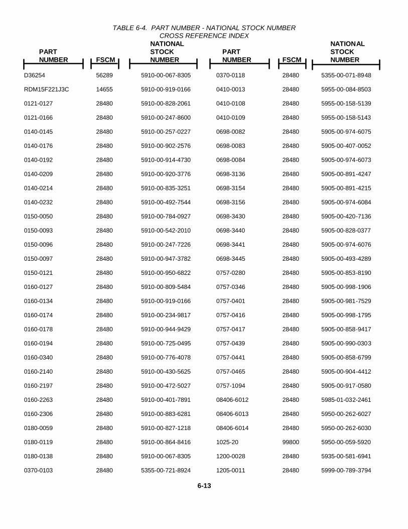
TABLE 6-4. PART NUMBER - NATIONAL STOCK NUMBERCROSS REFERENCE INDEX
NATIONAL NATIONALPART STOCK PART STOCKNUMBER FSCM NUMBER NUMBER FSCM NUMBER
D36254 56289 5910-00-067-8305 0370-0118 28480 5355-00-071-8948
RDM15F221J3C 14655 5910-00-919-0166 0410-0013 28480 5955-00-084-8503
0121-0127 28480 5910-00-828-2061 0410-0108 28480 5955-00-158-5139
0121-0166 28480 5910-00-247-8600 0410-0109 28480 5955-00-158-5143
0140-0145 28480 5910-00-257-0227 0698-0082 28480 5905-00-974-6075
0140-0176 28480 5910-00-902-2576 0698-0083 28480 5905-00-407-0052
0140-0192 28480 5910-00-914-4730 0698-0084 28480 5905-00-974-6073
0140-0209 28480 5910-00-920-3776 0698-3136 28480 5905-00-891-4247
0140-0214 28480 5910-00-835-3251 0698-3154 28480 5905-00-891-4215
0140-0232 28480 5910-00-492-7544 0698-3156 28480 5905-00-974-6084
0150-0050 28480 5910-00-784-0927 0698-3430 28480 5905-00-420-7136
0150-0093 28480 5910-00-542-2010 0698-3440 28480 5905-00-828-0377
0150-0096 28480 5910-00-247-7226 0698-3441 28480 5905-00-974-6076
0150-0097 28480 5910-00-947-3782 0698-3445 28480 5905-00-493-4289
0150-0121 28480 5910-00-950-6822 0757-0280 28480 5905-00-853-8190
0160-0127 28480 5910-00-809-5484 0757-0346 28480 5905-00-998-1906
0160-0134 28480 5910-00-919-0166 0757-0401 28480 5905-00-981-7529
0160-0174 28480 5910-00-234-9817 0757-0416 28480 5905-00-998-1795
0160-0178 28480 5910-00-944-9429 0757-0417 28480 5905-00-858-9417
0160-0194 28480 5910-00-725-0495 0757-0439 28480 5905-00-990-0303
0160-0340 28480 5910-00-776-4078 0757-0441 28480 5905-00-858-6799
0160-2140 28480 5910-00-430-5625 0757-0465 28480 5905-00-904-4412
0160-2197 28480 5910-00-472-5027 0757-1094 28480 5905-00-917-0580
0160-2263 28480 5910-00-401-7891 08406-6012 28480 5985-01-032-2461
0160-2306 28480 5910-00-883-6281 08406-6013 28480 5950-00-262-6027
0180-0059 28480 5910-00-827-1218 08406-6014 28480 5950-00-262-6030
0180-0119 28480 5910-00-864-8416 1025-20 99800 5950-00-059-5920
0180-0138 28480 5910-00-067-8305 1200-0028 28480 5935-00-581-6941
0370-0103 28480 5355-00-721-8924 1205-0011 28480 5999-00-789-3794
6-13

TABLE 6-4. PART NUMBER - NATIONAL STOCK NUMBERCROSS REFERENCE INDEX (Continued)
NATIONAL NATIONALPART STOCK PART STOCKNUMBER FSCM NUMBER NUMBER FSCM NUMBER
1250-0001 28480 5935-00-027-6759 5040-0700 28480 5340-00-978-7859
1250-0016 28480 5365-00-937-0638 5060-0703 28480 6625-00-412-1207
1250-0083 28480 5935-00-804-5144 8120-0078 28480 5995-00-995-9822
1251-0148 28480 5935-00-058-9423 8120-1348 28480 6150-01-004-8773
1251-2357 28480 5935-00-233-6728 9100-1612 28480 5950-00-438-4376
1400-0084 28480 5920-00-881-4636 9100-1613 28480 5950-00-431-3189
1850-0040 28480 5961-00-872-0882 9100-1680 28480 5950-00-107-6071
1850-0062 28480 5961-00-988-7630 9140-0131 28480 5950-00-431-3938
1853-0051 28480 5961-00-979-0108 9140-0158 28480 5950-00-059-5920
1854-0005 28480 5961-00-853-7942 9140-0210 28480 5950-00-431-3215
1901-0025 28480 5961-00-978-7468
1901-0026 28480 5961-00-060-8638
1901-0040 28480 5961-00-965-5917
1912-0007 28480 5961-00-904-0298
2N708 07263 5961-00-866-4810
2100-0067 28480 5905-00-850-6556
2100-0350 28480 5905-00-351-6128
2140-0047 28480 6240-00-912-5186
2140-0244 28480 6240-00-951-3376
30D106G025BB4 56289 5910-00-889-4854
3101-0033 28480 5930-00-977-1760
3101-1234 28480 5930-00-406-8746
3101-1248 28480 5930-00-476-9679
342014 75915 5920-00-881-4636
5C11A 56289 5910-00-883-0838
5020-0306 28480 5935-00-931-0420
5040-0234 28480 6250-00-910-8305
5040-0235 28480 6250-00-933-7369
6-14
Model 8406A Section VIIParagraphs 7-1 to 7-4
SECTION VII
SCHEMATIC DIAGRAMS
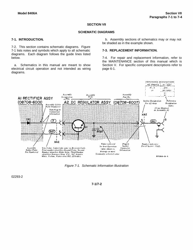
7-1. INTRODUCTION.
7-2. This section contains schematic diagrams. Figure7-1 lists notes and symbols which apply to all schematicdiagrams. Each diagram follows the guide lines listedbelow.
a. Schematics in this manual are meant to showelectrical circuit operation and not intended as wiringdiagrams.
b. Assembly sections of schematics may or may notbe shaded as in the example shown.
7-3. REPLACEMENT INFORMATION.
7-4. For repair and replacement information, refer tothe MAINTENANCE section of this manual which isSection V. For specific component descriptions refer topage 6-1.
Figure 7-1. Schematic Information Illustration
02293-2
7-1/7-2

Model 8406A
SECTION VIII
BACKDATING INFORMATION
This manual applies to instruments with Serial Prefixes 649-, and 737-. Listed below are changes to bemade to the manual so that it will apply directly to Prefixes 532-, and 541-.
InstrumentSerial No. Prefix Change Number
541- 1
532- 1 and 2
02293-2
8-1/(8-2 blank)
MANUAL CHANGES
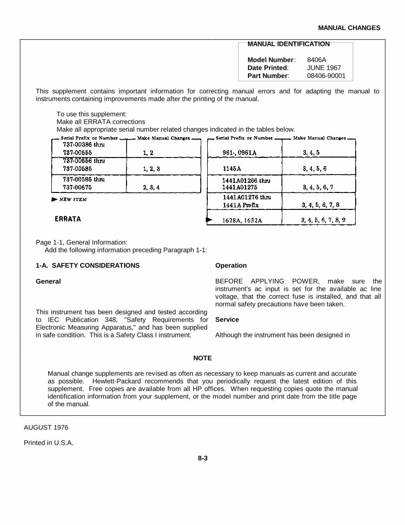
MANUAL IDENTIFICATION
Model Number: 8406ADate Printed: JUNE 1967Part Number: 08406-90001
This supplement contains important information for correcting manual errors and for adapting the manual toinstruments containing improvements made after the printing of the manual.
To use this supplement:Make all ERRATA correctionsMake all appropriate serial number related changes indicated in the tables below.
Page 1-1, General Information:Add the following information preceding Paragraph 1-1:
1-A. SAFETY CONSIDERATIONS
General
This instrument has been designed and tested accordingto IEC Publication 348, "Safety Requirements forElectronic Measuring Apparatus," and has been suppliedin safe condition. This is a Safety Class I instrument.
Operation
BEFORE APPLYING POWER, make sure theinstrument's ac input is set for the available ac linevoltage, that the correct fuse is installed, and that allnormal safety precautions have been taken.
Service
Although the instrument has been designed in
NOTE
Manual change supplements are revised as often as necessary to keep manuals as current and accurateas possible. Hewlett-Packard recommends that you periodically request the latest edition of thissupplement. Free copies are available from all HP offices. When requesting copies quote the manualidentification information from your supplement, or the model number and print date from the title pageof the manual.
AUGUST 1976
Printed in U.S.A.
8-3
ERRATA (Cont'd)
accordance with international safety standards, theinformation, cautions, and warnings in this manual mustbe followed to ensure safe operation and to keep theinstrument safe. Service and adjustments should beperformed only by qualified service personnel.
Adjustment or repair of the opened instrument with theac power connected should be avoided as much aspossible and, when inevitable, should be performed onlyby a skilled person who knows the hazard involved.
Capacitors inside the instrument may still be chargedeven though the instrument has been disconnected fromits source of supply.
Make sure only fuses of the required current rating andtype (normal blow, time delay, etc.) are used forreplacement. Do not use repaired fuses or short circuitthe fuse holders.
Whenever it is likely that the protection has beenimpaired, make the instrument inoperative and secure itagainst any unintended operation.
8-4
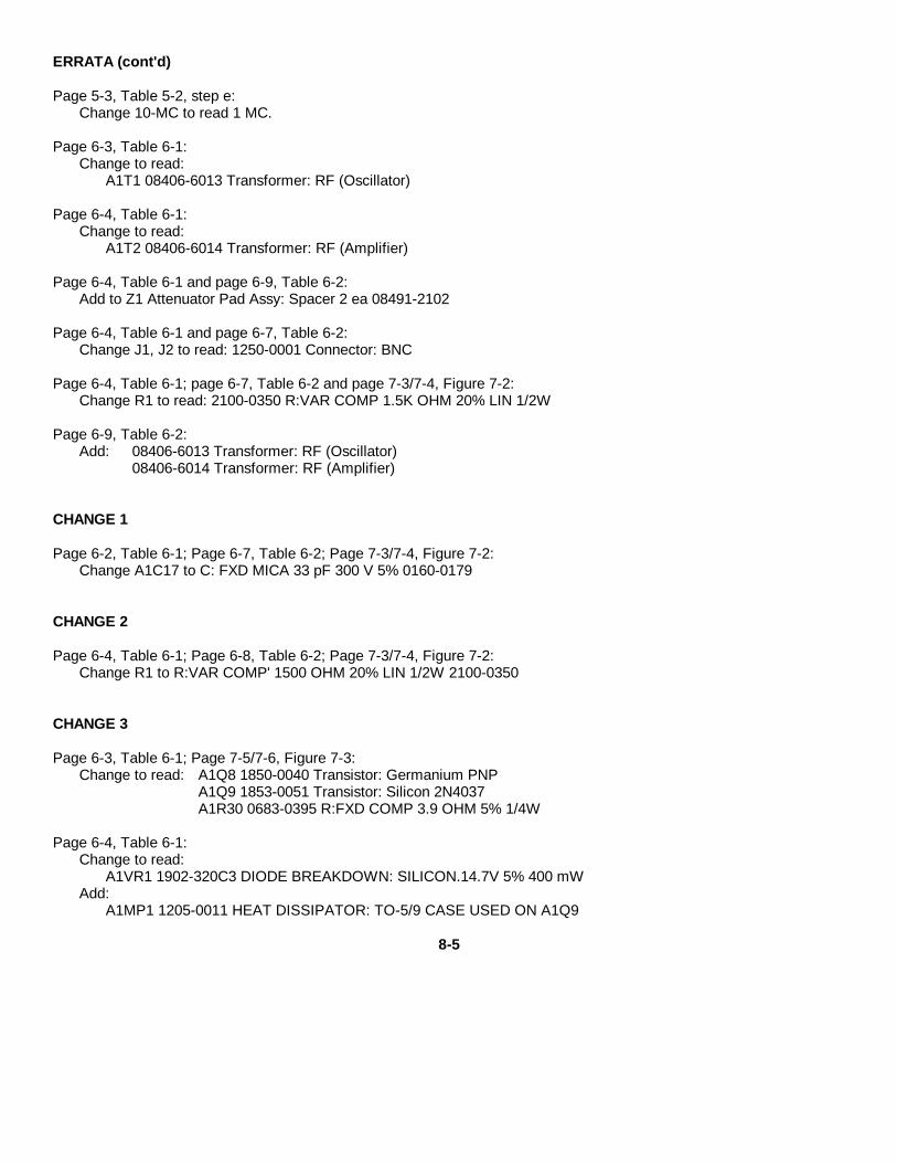
ERRATA (cont'd)
Page 5-3, Table 5-2, step e:Change 10-MC to read 1 MC.
Page 6-3, Table 6-1:Change to read:
A1T1 08406-6013 Transformer: RF (Oscillator)
Page 6-4, Table 6-1:Change to read:
A1T2 08406-6014 Transformer: RF (Amplifier)
Page 6-4, Table 6-1 and page 6-9, Table 6-2:Add to Z1 Attenuator Pad Assy: Spacer 2 ea 08491-2102
Page 6-4, Table 6-1 and page 6-7, Table 6-2:Change J1, J2 to read: 1250-0001 Connector: BNC
Page 6-4, Table 6-1; page 6-7, Table 6-2 and page 7-3/7-4, Figure 7-2:Change R1 to read: 2100-0350 R:VAR COMP 1.5K OHM 20% LIN 1/2W
Page 6-9, Table 6-2:Add: 08406-6013 Transformer: RF (Oscillator)
08406-6014 Transformer: RF (Amplifier)
CHANGE 1
Page 6-2, Table 6-1; Page 6-7, Table 6-2; Page 7-3/7-4, Figure 7-2:Change A1C17 to C: FXD MICA 33 pF 300 V 5% 0160-0179
CHANGE 2
Page 6-4, Table 6-1; Page 6-8, Table 6-2; Page 7-3/7-4, Figure 7-2:Change R1 to R:VAR COMP' 1500 OHM 20% LIN 1/2W 2100-0350
CHANGE 3
Page 6-3, Table 6-1; Page 7-5/7-6, Figure 7-3:Change to read: A1Q8 1850-0040 Transistor: Germanium PNP
A1Q9 1853-0051 Transistor: Silicon 2N4037A1R30 0683-0395 R:FXD COMP 3.9 OHM 5% 1/4W
Page 6-4, Table 6-1:Change to read:
A1VR1 1902-320C3 DIODE BREAKDOWN: SILICON.14.7V 5% 400 mWAdd:
A1MP1 1205-0011 HEAT DISSIPATOR: TO-5/9 CASE USED ON A1Q9
8-5
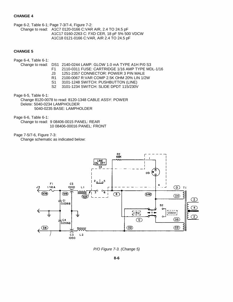
CHANGE 4
Page 6-2, Table 6-1; Page 7-3/7-4, Figure 7-2:Change to read: A1C7 0120-0166 C:VAR AIR, 2.4 TO 24.5 pF
A1C17 0160-2263 C: FXD CER, 18 pF 5% 500 VDCWA1C18 0121-0166 C:VAR, AIR 2.4 TO 24.5 pF
CHANGE 5
Page 6-4, Table 6-1:Change to read: DS1 2140-0244 LAMP: GLOW 1.0 mA TYPE A1H P/0 S3
F1 2110-0311 FUSE: CARTRIDGE 1/16 AMP TYPE MDL-1/16J3 1251-2357 CONNECTOR: POWER 3 PIN MALER1 2100-0067 R:VAR COMP 2.5K OHM 20% LIN 1/2WS1 3101-1248 SWITCH: PUSHBUTTON (LINE)S2 3101-1234 SWITCH: SLIDE DPDT 115/230V
Page 6-5, Table 6-1:Change 8120-0078 to read: 8120-1348 CABLE ASSY: POWERDelete: 5040-0234 LAMPHOLDER
5040-0235 BASE: LAMPHOLDER
Page 6-6, Table 6-1:Change to read: 9 08406-0015 PANEL: REAR
10 08406-00016 PANEL: FRONT
Page 7-5/7-6, Figure 7-3:Change schematic as indicated below:
P/O Figure 7-3. (Change 5)
8-6

CHANGE 6
Page 6-2, Table 6-1 and Page 7-3/7-4, Figure 7-2:Change A1C17 to C: FXD MICA 60 pF 300 V 5% 0140-0214 (*) Factory Selected Component.
Page 6-5, Table 6-1:Add: 0370-1400 KNOB: MINT GRAY PUSHBUTTON 11116 IN DIA 1MC, 10MC, 100MC EXT TRIG.
Page 6-6, Table 6-1 Cabinet Parts:Change items 6 through 10 to read:
6 5000-8565 COVER: SIDE (OLIVE GRAY)5000-0703 COVER: SIDE (BLUE GRAY)
7 5060-8555 COVER ASSEMBLY:TOP (OLIVE GRAY)5060-0709 COVER ASSEMBLY:TOP (BLUE GRAY)
8 5000-8571 COVER ASSEMBLY:BOTTOM (OLIVE GRAY)5000-0700 COVER ASSEMBLY:BOTTOM (BLUE GRAY)
9 08406-00015 PANEL: REAR
10 08406-00017 PANEL: FRONT (MINT GRAY)08406-00016 PANEL: FRONT (LIGHT GRAY)
CHANGE 7
Page 6-4, Table 6-1:Change RI to 2100-2769, R:VAR 2.5K OHM 20% 2W.
CHANGE 8
Page 6-2, Table 6-1:Change A1C6 to 0160-2306, C:FXD CER 27 pF 5% 300 V, Factory Selected Part.Change A1C17 to 0140-0145, C: FXD MICA 22 pF 5% 500 VDCW, Factory Selected Part.
Page 7-3, Figure 7-2:Change the value of A1C6 to A1C6* 27 pF.Change the value of A1C17* to 22 pF.
>CHANGE 9
Page 1-1, Table 1-1:Change "Peak amplitude*" to "Typical amplitude*".
8-7/(8-8 blank)

APPENDIX AREFERENCES
The following publications contain information applicable to the operation and maintenance of the SG-1129/U (HP-8406A) Frequency Comb Generator.
TM 11-6625-2781-14&P Operator's, Organizational, Direct Support, and GeneralSupport Maintenance Manual Including Repair Partsand Special Tools List: Spectrum Analyzer IP-1216(P)/GR (HP-141T)
TM 11-6625-700-10 Operator's Manual: Digital Readout, Electronic CounterAN/USM-207
TM 11-6625-573-14 Operator's, Organizational, Direct Support, and GeneralSupport Maintenance Manual: Generator SignalAN/GRM-50
TM 11-6625-1633-12 Operator's and Organizational Maintenance ManualIncluding Repair Parts and Special Tools List:Generator, Signal AN/URM-149
TM 11-6625-320-12 Operator's and Organizational Maintenance Manual:Voltmeter, Meter ME-30( )/U
TM 11-6625-444-14-1 Operator's, Organizational, Direct Support, and GeneralSupport Maintenance Manual Including Repair Partsand Special Tools List: Voltmeter Digital AN/GSM-64B
TM 11-6625-524-14 Operator's, Organizational, and Field MaintenanceManual: Voltmeter, Electronic AN/URM-145
AR 55-38 Reporting of Transportation Discrepancies in Shipment
AR735-11-2 Reporting of Item Discrepancies Attributable to Shippers
DA PAM 310-4 Index of Technical Publications: Technical Manuals,Technical Bulletins, Supply Manuals (Types 7, 8 and9), Supply Bulletins, and Lubrication Orders
DA PAM 310-7 US Army Equipment Index of Modification Work Orders
MIL-F-14702 Finishes for Ground Signal Equipment
SB 11-573 Painting and Preservation Supplies Available for FieldUse for Electronics Command Equipment
A-1
APPENDIX A - Continued
SB 38-100 Preservation, Packaging and Packing Materials,Supplies and Equipment Used by the Army
SB 700-20 Army Adopted/Other Items Selected forAuthorization/List of Reportable Items
TB SIG 222 Solder and Soldering
TM 38-750 The Army Maintenance Management System (TAMMS)
TM 750-244-2 Procedures for Destruction of Electronics Materiel toPrevent Enemy Use (Electronics Command)
A-2
APPENDIX D
MAINTENANCE ALLOCATION
Section I. INTRODUCTION
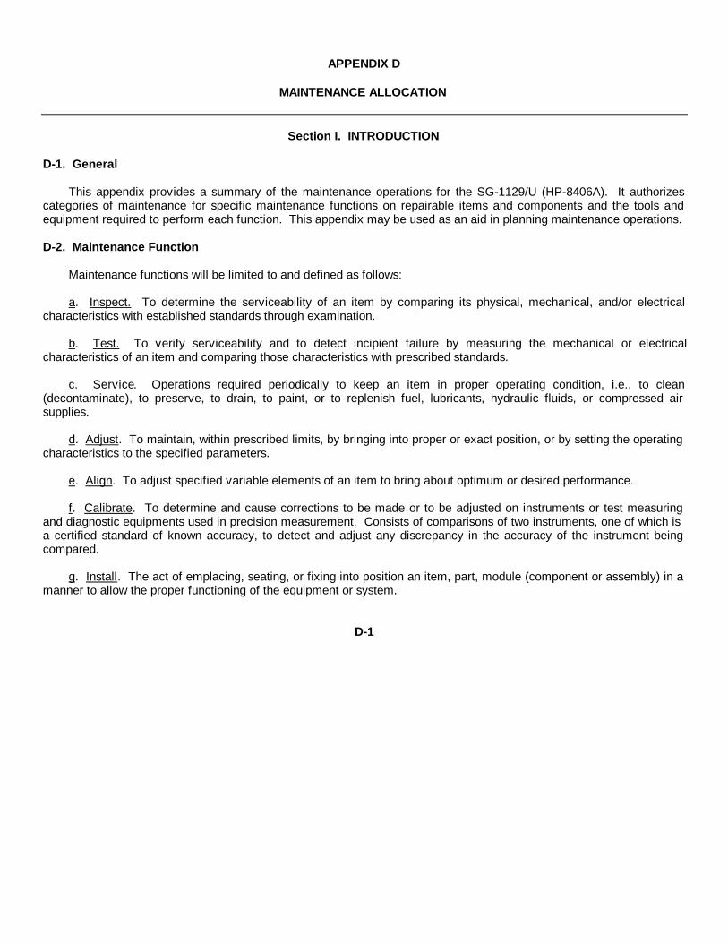
D-1. General
This appendix provides a summary of the maintenance operations for the SG-1129/U (HP-8406A). It authorizescategories of maintenance for specific maintenance functions on repairable items and components and the tools andequipment required to perform each function. This appendix may be used as an aid in planning maintenance operations.
D-2. Maintenance Function
Maintenance functions will be limited to and defined as follows:
a. Inspect. To determine the serviceability of an item by comparing its physical, mechanical, and/or electricalcharacteristics with established standards through examination.
b. Test. To verify serviceability and to detect incipient failure by measuring the mechanical or electricalcharacteristics of an item and comparing those characteristics with prescribed standards.
c. Service. Operations required periodically to keep an item in proper operating condition, i.e., to clean(decontaminate), to preserve, to drain, to paint, or to replenish fuel, lubricants, hydraulic fluids, or compressed airsupplies.
d. Adjust. To maintain, within prescribed limits, by bringing into proper or exact position, or by setting the operatingcharacteristics to the specified parameters.
e. Align. To adjust specified variable elements of an item to bring about optimum or desired performance.
f. Calibrate. To determine and cause corrections to be made or to be adjusted on instruments or test measuringand diagnostic equipments used in precision measurement. Consists of comparisons of two instruments, one of which isa certified standard of known accuracy, to detect and adjust any discrepancy in the accuracy of the instrument beingcompared.
g. Install. The act of emplacing, seating, or fixing into position an item, part, module (component or assembly) in amanner to allow the proper functioning of the equipment or system.
D-1
h. Replace. The act of substituting a serviceable like type part, subassembly, or module (component or assembly)for an unserviceable counterpart.
i. Repair. The application of maintenance services (inspect, test, service, adjust, align, calibrate, replace) or othermaintenance actions (welding, grinding, riveting, straightening, facing, remachining, or resurfacing) to restoreserviceability to an item by correcting specific damage, fault, malfunction, or failure in a part, subassembly, module(component or assembly), end item, or system.
j. Overhaul. That maintenance effort (service/action) necessary to restore an item to a completelyserviceable/operational condition as prescribed by maintenance standards (i.e. DMWR) in appropriate technicalpublications. Overhaul is normally the highest degree of maintenance performed by the Army. Overhaul does notnormally return an item to like new condition.
k. Rebuild. Consists of those services/actions necessary for the restoration of unserviceable equipment to a likenew condition in accordance with original manufacturing standards. Rebuild is the highest degree of materialmaintenance supplied to Army equipment. The rebuild operation includes the act of returning to zero those agemeasurements (hours, miles, etc.) considered in classifying Army equipments/components.
D-3. Column Entries.
a. Column 1, Group Number. Column 1 lists group numbers, the purpose of which is to identify components,assemblies, subassemblies, and modules with the next higher assembly.
b. Column 2, Component/Assembly. Column 2 contains the noun names of components, assemblies,subassemblies, and modules for which maintenance is authorized.
c. Column 3, Maintenance Functions. Column 3 lists the functions to be performed on the item listed in column 2.When items are listed with-out maintenance functions, it is solely for the purpose of having the group numbers in theMAC and RPSTL coincide.
d. Column 4, Maintenance Category. Column 4 specifies, by the listing of a "work time" figure in the appropriatesubcolumn(s), the lowest level of maintenance authorized to perform the function listed in column 3. This figurerepresents the active time required to perform that maintenance function at the indicated category of maintenance. If thenumber or complexity of the tasks within the listed maintenance function vary at different maintenance categories,appropriate "work time" figures will be shown for each category. The number of task-hours specified by the "work time"figure represents the average time required to restore an item
D-2
(assembly, subassembly, component, module, end item or system) to a serviceable condition under typical fieldoperating conditions. This time includes preparation time, troubleshooting time, and quality assurance/quality controltime in addition to the time required to perform the specific tasks identified for the maintenance functions authorized inthe maintenance allocation chart. Subcolumns of column 4 are as follows:
C - Operator/Crew
O - Organizational
F - Direct Support
H - General Support
D - Depot
e. Column 5, Tools and Equipment. Column 5 specifies by code those common tool sets (not individual tools) andspecial tools, test, and support equipment required to perform the designated function.
f. Column 6, Remarks. Column 6 contains an alphabetic code which leads to the remark in Section V, Remarks,which is pertinent to the item opposite the particular code.
D-4. Tool and Test Equipment Requirements (Section III)
a. Tool or Test Equipment Reference Code. The numbers in this column coincide with the numbers used in thetools and equipment column of the MAC. The numbers indicate the applicable tool or test equipment for themaintenance functions.
b. Maintenance Category. The codes in this column indicate the maintenance category allocated the tool or testequipment.
c. Nomenclature. This column lists the noun name and nomenclature of the tools and test equipment required toperform the maintenance functions.
d. National/NATO Stock Number. This column lists the National/NATO stock number of the specific tool or testequipment.
e. Tool Number. This column lists the manufacturer's part number of the tool followed by the Federal Supply Codefor manufacturers (5-digit) in parentheses.
D-3

D-5. Remarks (Section V)
a. Reference Code. This code refers to the appropriate item in Section II, column 6.
b. Remarks. This column provides the required explanatory information necessary to clarify items appearing inSection II.
D-4
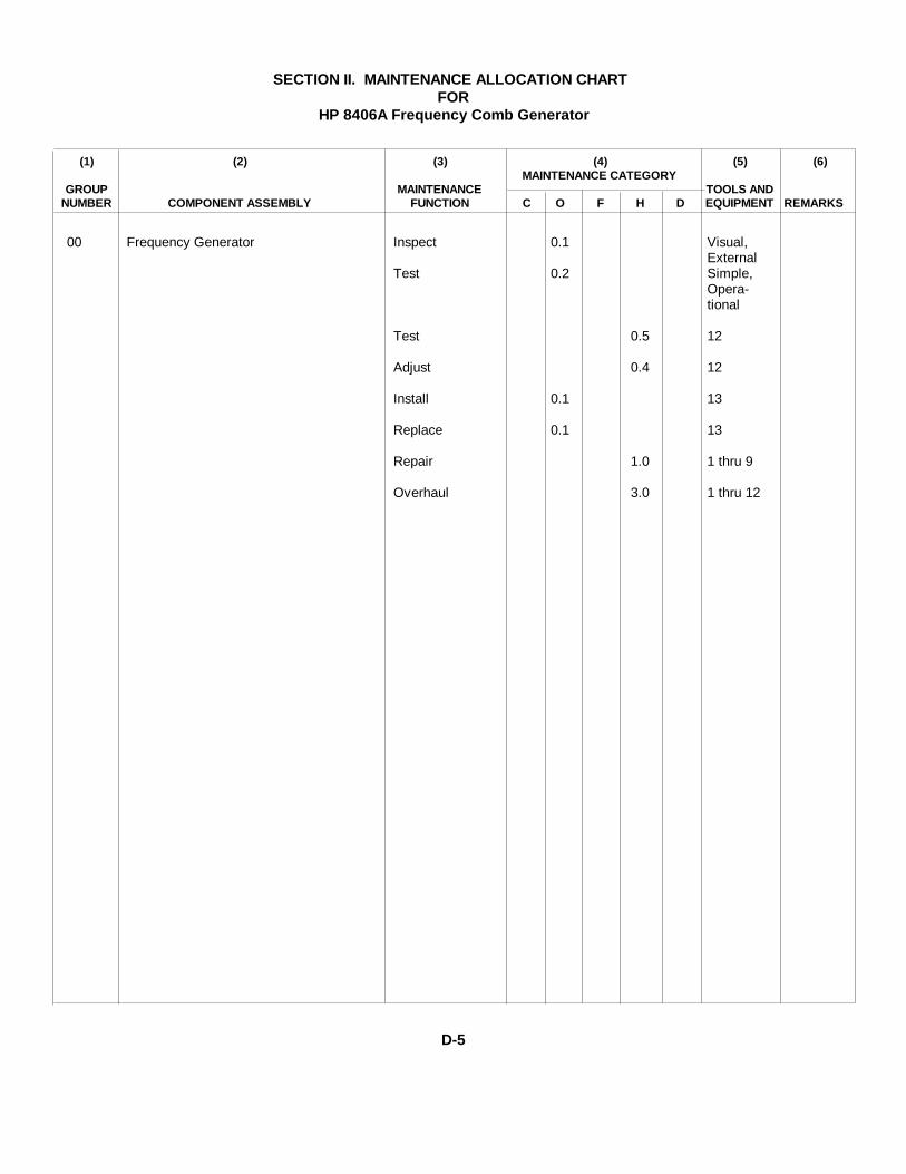
SECTION II. MAINTENANCE ALLOCATION CHARTFOR
HP 8406A Frequency Comb Generator
(1) (2) (3) (4) (5) (6)MAINTENANCE CATEGORY
GROUP MAINTENANCE TOOLS ANDNUMBER COMPONENT ASSEMBLY FUNCTION C O F H D EQUIPMENT REMARKS
00 Frequency Generator Inspect 0.1 Visual,External
Test 0.2 Simple,Opera-tional
Test 0.5 12
Adjust 0.4 12
Install 0.1 13
Replace 0.1 13
Repair 1.0 1 thru 9
Overhaul 3.0 1 thru 12
D-5

SECTION III. TOOL AND TEST EQUIPMENT REQUIREMENTSFOR
HP 8406A Frequency Comb Generator
TOOL OR TEST MAINTENANCE NATIONAL/ TOOL
EQUIPMENT CATEGORY NOMENCLATURE NATO STOCK NUMBERREF CODE NUMBER
1 H,D Analyzer, Spectrum IP-1216/PGR 6625-00-424-4370
2 H,D Plug-In PL-1400/U 6625-00-422-4314
3 H,D Counter, Frequency, Electronic 6625-00-044-3228AN/USM-207
4 H,D Generator, Signal AN/GRM-SOC 6625-00-003-3238
5 H,D Generator, Signal AN/URM-149 6625-00-903-3501
6 H,D Multimeter ME-30E/U 6625-00-643-1670
7 H,D Voltmeter AN/GSM-64 6625-00-022-7894
8 H,D Voltmeter AN/URM-145 6625-00-973-3986
9 H,D Transformer, Variable, Power 5950-00-235-2086CN-16/U
10 D Notch Filter HP 8439A or equal
11 D Bandpass Filter HP 8431A or equal
12 H,D Tool Kit TK-100/G 5180-00-605-0079
Common tools necessary for the performance of this maintenancefunction are available to maintenance personnel for themaintenance category listed.
D-6
By Order of the Secretary of the Army:
E. C. MEYERGeneral, United States Army
Official: Chief of Staff
J. C. PENNINGTONMajor General, United States Army
The Adjutant General
Distribution:
Active Army:
HISA (Ft Monmouth) (21) USAES (2)USAINSCOM (2) USAICS (3)COE (1) MAAG (1)TSG (1) USARMIS (1)DARCOM (1) USAERDAW (1)TRADOC (2) Ft Carson (5)OS Maj Comd (4) Ft Gordon (10)TECOM (2) Ft Gillem (10)USAACC (4) Ft Richardson (CERCOM Ofc) (2)MDW (1) Army Dep (1) exceptArmies (2) SAAD (30)Corps (2) TOAD (14)Svc Colleges (1) SHAD (2)USASIGS (5) USA Dep (1)USAADS (2) Sig Sec USA Dep (1)USAFAS (2) Units org under fol TOE: (2)USAARMS (2) 29-207USAIS (2) 29-610
NG: NoneUSAR: None
For explanataion of abbreviations used see, AR 310-50.

Section VIIFigure 7-2
Figure 7-2. Generator
7-3/7-4


PIN: 045625-000