TM 11-6625-2398-15-3 TECHNICAL MANUAL OPERATOR'S ...
141
TM 11-6625-2398-15-3 TECHNICAL MANUAL OPERATOR'S, ORGANIZATIONAL, DIRECT SUPPORT, GENERAL SUPPORT, AND DEPOT MAINTENANCE MANUAL INCLUDING REPAIR PARTS AND SPECIAL TOOLS LISTS TEST FACILITIES SET AN/TPM-24(V)3 (NSN 6625-00-133-7865) This copy is a reprint which includes current pages from Changes 1 and 2. The title was changed by Change 2. HEADQUARTERS, DEPARTMENT OF THE ARMY AUGUST 1971
Transcript of TM 11-6625-2398-15-3 TECHNICAL MANUAL OPERATOR'S ...

TM 11-6625-2398-15-3
TECHNICAL MANUAL
OPERATOR'S, ORGANIZATIONAL, DIRECT SUPPORT, GENERAL SUPPORT,AND DEPOT MAINTENANCE MANUAL
INCLUDING REPAIR PARTS AND SPECIAL TOOLS LISTS
TEST FACILITIES SET AN/TPM-24(V)3
(NSN 6625-00-133-7865)
This copy is a reprint which includes currentpages from Changes 1 and 2. The title waschanged by Change 2.
HEADQUARTERS, DEPARTMENT OF THE ARMY
AUGUST 1971

WARNING
DANGEROUS VOLTAGE EXISTS IN EQUIPMENT WHICH WLLBE INTERCONNECTED BY THIS TEST FACILITIES SET
DON'T TAKE CHANCES!EXTREMELY DANGEROUS VOLTAGE
EXISTS IN THE FOLOWING UNIT:
Receiver -Transmitter, Radio RT-903/TPX-50 1000 volts
TM 11-6625-2398-15-3
TECHNICAL MANUAL HEADQUARTERSDEPARTMENT OF THE ARMY
No. 11-6625-2398-15-3 WASHINGTON, DC, 10 August 1971
OPERATOR'S, ORGANIZATIONAL, DIRECT SUPPORT,GENERAL SUPPORT, AND DEPOT MAINTENANCE MANUAL
TEST FACILITIES SET AN/TPM-24(V)3(NSN 6625-00-133-7865)
REPORTING OF ERRORS
You can help improve this manual by calling attention to errors, recommending improvements, and stating your reasonsfor the recommendations.
Your letter or DA Form 2028 (Recommended Changes to Publications and Blank Forms) should be mailed directly toCommander, US Army Communications and Electronics Materiel Readiness Command, ATTN: DRSEL-ME-MQ, FortMonmouth, NJ 07703. A reply will be furnished directly to you.
Paragraph PageCHAPTER 1. INTRODUCTIONSECTION I. General........................................................................ ........................ 1-1 1-1
II Description and data ................................................................ ........... 1-4 1-1CHAPTER 2. INSTALLATION ................................................................... ............... 2-4 2-1
3. OPERATING INSTRUCTlONSSECTION I. Operator’s controls and connection ..................................................... 3-1 3-1
II. Operation .......................................................................... .................. 3-3 3-3CHAPTER 4. OPERATOR'S AND ORGANIZATION MAINTENANCE ...................... 4-1 4-1
5. FUNCTIONING.................................................................................... 5-1 5-16. GENERAI. SUPPORT MIAINTENANE
SECTION I. General troubleshooting information .................................................... 6-1 6-1II. Component troubleshooting ................................................................. 6-4 6-2III. Component testing, calibratration ............................................... ......... 6-7 6-3
CHAPTER 7. REPAIRS ........................................................................ ................... 7-1 7-18. GENERAL SUPPORT TESTING PROCEDURES ................................... 8-1 8-19. DEPOT OVERHAUL STANDARDS .................................................... 9-1 9-110. SHIPMENT AND LIMITED STORAGE. AND DEMOLITION TO
PREVENT ENEMY USESECTION I. Shipment and limited storage............................................................... 10-1 10-1
II. Demolition of material to prevent enemy use ....................................... 10-3 10-2APENDIX A. REFERENES .................................................................................. ... A-1
B. BASIC ISSUE ITEMS LIST (Not applicable)C. MAINTENAN('E ALLOCATION
SECTION I. Introduction ................................................................ ......................... C-1II. Maintenance Allocation Chart for Test Facilities Set ANfTPM-4(V)3..... C-3III. Tools and Test Equipment Requirements for Test Facilities Set ANITPM-24(V)3 C-5IV. Remarks .......................................................................... .................. C-6
INDEX........................................................................................................................... Index 1
Change 2 i

TM 11-6625-2398-15-3
Figure 1-1. Test Facilities Set AN/TPM-24(V)3
1-0

TM 11-6625-2398-15-3CHAPTER 1
INTRODUCTION
Section I. GENERAL1-1. Scope
This manual describes Test Facilities Set AN/TPX-24(V)3(fig.1-1) and provides instructions for installation, use, andmaintenance. It includes instructions for cleaning,inspection, troubleshooting, testing, calibration, repair andreplacement. It also lists tools, materials, and testequipment required for maintenance. A functionalanalysis of the equipment is also covered.
1-2. Indexes of Publications
a. DA Pam 310-4. Refer to the latest issue of DAPam 310-4 to determine whether there are new editions,changes or additional publications pertaining to theequipment .
b. DA Pam 310-7. Refer to DAA Pam 310-7 todetermine whether there are modification work orders(MWO’s) pertaining to the equipment.
1-3. Forms and Records
a. Reports of Maintenance level and UnsatisfactoryEquipment . Maintenance forms records and reportswhich are to be used by maintenance personnel at allmaintenance level are listed in and prescribed by TM 38-750.
b. Report of packaging and Handling Deficiencies .Fill out and forward DD Form 6 (Packaging ImprovementReport) as prescribed in AR 700-58/NAVSUPINST4030.29/AFR 71-13/MCO P4030.29A, and DLAR 4145.8.
c. Discrepancy in Shipment Report (DISREP) (SF361). Fill out and forward Discrepancy in ShipmentReport (DISREP) (SF 361) as prescribed in AR 55-38/NAVSUPINST 4610.33A/AFR 75-18/ MCO P4610.19Band DLAR 5400.15.
1-3.1. Destruction of Army Electronics Materiel
Destruction of Army electronics materiel to preventenemy use shall be in accordance with TM 750-244-2.
1-3.2. Reporting Equipment ImprovementRecommendations (EIR)
EIR' s will be prepared using SF 368, Quality DeficiencyReport. Instructions for preparing EIR's are provided inTM 38-750, the Army Maintenance Management System.EIR's should be mailed directly to Commander, US ArmyCommunications and Electronics Materiel ReadinessCommand, ATTN: DRSEL-ME-MQ, Fort Monmouth. NewJersey 07703. A reply will be furnished directly to you.
Section II. DESCRIPTION AND DATA
1-4. Purpose and Usea. Test Facilities Set AN TPM -24(V) 3 is a portable
set of special test accessories used to support themaintenance of Interrogator Set AN TPX -50 If containscable assemblies a hybrid attenuator, a front panel testadapter and minor components (including connectoradapters, dummy lads, extender boards and similar items)all housed in a transit case.
b. Five of the AN TPX -24(V) 3 cable assembliesprovide intraconnection between the major assemblies of
Interrogator Set Group OX-8/TPX-50 when SignalProcessor CP-936/TPX , and Radio Receiver-TransmitterRT-903/TPX-50 are removed from Interrogator Set GroupCabinet CY-6442 TPX -50. Two other AN/TPM -24 (V)3cable assemblies Two other AN/TPM-24(V)3 cableassemblies connect the OX-8/TPX-50 to external powerand triggering sources. One AN/TPM-24(V)3 cableassembly and minor components provide termination forthe rf sum and rf difference channels of Interrogator set
Change 2 1-1

TM 11-6625-2398-I5-3
AN/TPX-50. When additional connections are made(using cables supplied with the AN/TPX-50) from the OX-8/TPX-50 to Interrogator Set Control C-7651/TPX-50 andInterrogator Computer KIR-1A(V-2)/TSEC, InterrogatorSet AN/TPX50 may be energized in a hot mock-upconfiguration for maintenance purposes.
CAUTIONTo avoid damage to the equipmentunder test DO NOT energizeInterrogator Set AN/TPX-50 beforeplacing a load on the rf sum anddifference channels (jacks 1J9 and1J10). To terminate for testing,connect cable W45 to 1J9 and adapterUG-201A/U (CP7/CP8) to 1J10.Terminate the cable and adapter withElectrical dummy loads DA-558/TPM-24(V) (terminations AT3/ AT4).
c. The hybrid attenuator, three associated AN/TPM-24(V)3 cable assemblies and minor components are usedin conjunction with other test equipment in performingvarious rf measurements on the AN/TPX-50. Rf sumchannel and rf difference channel parameters may bemeasured at reply and challenge frequencies.
d. The front panel test adapter connects to the TESTjack on the front panel of the RT-903/ TPX-50. It providesa convenient means of selecting and monitoring varioussignals of the RT-903/TPX-50 using external testequipment.
e. The remaining cable assemblies and minorcomponents of the AN/TPM-24(V)3 are used inperforming specific maintenance procedures on theAN/TPX-50. Maintenance procedures for the AN/TPX-50are covered in the following technical manuals:
TM 11-5895-687-35-1 DS, GS and DepotMaintenance Manual-InterrogatorSet AN/TPX-50
TM 11-5895-87-35-2 DS, GS and DepotMaintenance ManualSignal ProcessorCP-936/TPX-50
TM 11-5895-687-35-3 DS, GS and DepotMaintenance ManualSynchronize,Electrical SN-421/TPX-50
TM 11-5895-87-35-4 DS, GS and DepotMaintenance ManualReceiver-Trans-mitter, Radio RT-903/TPX-50
1-5. Technical CharacteristicsThe technical characteristics of the components of theHybrid Attenuator Assembly CN-1322/ TPM-24(V) are asfollows:
a. Hybrid Junction.Impedance 50 ohms, nominalFrequency range 1000 - 1200MHzNominal coupling 3, +0.3, -0dBMax. deviation ±0.25dBMax. VSWR 1.3 to 1Min. isolation 20dB between sum and
differencePower rating 5 kilowatts peak, 50
watt averageb. Attenuator.
Impedance. 50 ohms, nominalFrequency range 1000 - 1200MHzVariable atten-uation 0 - 25dB, min.Calibration 0 to 10dB range ±0.35dBaccuracy at 1090 max.MHz 11 to 20dB range
±0.50dB max.21 to 25dB range± 0.60dB max.
Accuracy over ±2.5dB max. includingthe band insertion lossInsertion loss 0.5dB, max.VSWR 1.5dB, max.Power rating 6 kilowatts peak, 10
watts average
1-6. Common Namesa. A list of nomenclature and common names
assignments for Test Facilities Set AN/TPM24(V)3 isgiven below.
Common name NomenclatureAdapter CP1 Adapter,. Connector UG-1897/
TPM-24(V)Adapter CP2/CP3/CP4 Adapter. Connector UG-1896/
TPM-24(V)Adapter CP5/CP6 Adapter, Connector UG-1S/
1-2

TM 11-6625-2398-I5-3
Common name NomenclatureAdapter CP7/CP8 ................... Adapter UG-201A/UAdapter Tee CP9/CP10/ Adapter Connector UG- 274B/UCP11Attenuator AT1/AT2 ................ Attenuator, fixed CN-1321/
TPM-24(V)Cable W13.............................. Cable Assembly, Radio
Frequency CG-3608/TPM-24(V)
Cable W14/W15 .................... Cable Assembly, RadioFrequency CG-409F/U (6 ft.)
Cable W16 ............................. Cable Assembly, RadioFrequency CG-3610/TPM-24(V)
Cable W21.............................. Cable Assembly, RadioFrequency CG-3611/TPM-24(V)
Cable W32.............................. Cable Assembly, Power,Electrical CX-12227/TPM-24(V)
Cable W39 ............................. Cable Assembly, RadioFrequency, Branched CGC3616/TPM-24(V)
Cable W40 ............................. Cable Assembly, SpecialPurpose Electrical CX-12222/TPM-24(V)
Cable W41 ............................. Cable Assembly, SpecialPurpose, Electrical CX-12223/TPM-24(V)
Cable W42 ............................. Cable Assembly, SpecialPurpose, Electrical CX-12224/TPM-24(V)
Cable W43 ............................. Cable Assembly, SpecialPurpose, Electrical CX-12225/TPM-24(V)
Cable W45 ............................. Cable Assembly, RadioFrequency CG-3612/TPM-24(V)
Cable W47.............................. Cable Assembly, RadioFrequency CG-3613/TPM-24(V)
Cable W48 ............................. Cable Assembly, RadioFrequency, Branched CG-3617/TPM-24(V)
Extender board A3/A4 . ........... Extender, Circuit Board MX-8560/TPM-24(V)
Extender board A5 ................. Extender, Circuit Board MX-8563r/TPM-24(V)
Front panel test adapter ......... Adapter, Test MX-8565TPM-24(V)
Hybrid attenuator Hybrid Attenuator AssemblyCN-1322/TPM-24(V)
Common name NomenclatureIndex card ............................. Card, IndexPrinted-circuit board ex Extractor, Circuit Board (8.5 in.tractor MPI wide)Printed-circuit board ex Extractor, Circuit Board (8.7 in.tractor MP2 wide)Termination AT3/AT4 ............ Dummy Loads Electrical DA-
558/TPM-24(V)Termination AT3/AT6 ............ Dummy Load, Electrical DA-
559/TPM-24(V)Test facilities set .................... Test Facilities Set AN/TPM-
24(V)3Transit case ........................... Case, Test Facilities Set CY-
6825/TPM-24(V)b. A list of nomenclature and common name
assignments for Interrogator Set AN/TPX-50 and cablessupplied with Interrogator Set AN/ TPX-50 is given below.
Common name NomenclatureCable W 1 .............................. Cable Assembly, Special
Purpose, Electrical CX-10876/U (7'8')
Cable W2* ' ............................ Cable Assembly, SpecialPurpose, Electrical, BranchedCX-10878/TPX-60 (6')
Control box ............................ Control, Interrogator Set C-7651/TPX-50
IFF Set ................................... -Interrogator Set AN/TPX4-0Interrogator group .................. -Interrogator Set Group OX-/1
TPX-50Interrogator group case ......... Cabinet, Interrogator Set Group
CY-6442/TPX-50Processor .............................. -Signal Processor CP-936FTPX-
50Receiver-transmitter .............. .Receiver-Transmitter, Radio
RT-903/TPX-50Synchronizer ......................... Synchronizer, Electrical SN421/TPX-50* Supplied with, but not part of, Interrogator Set AN/TPX-60.
1-7. Items Comprising Test Facilities Set AN/TPM-24(V)3NOTE
This listing is based on original shipmentof Contract DAAB05-69C-0415. Refer toparagraph 1-6 for nomenclature of itemslisted below.
a. Major Components.Dimensions (in)
Quantity Item Height Depth Width Weight Figure FSN(lb) No.
1 Transit came MP4 17 18 21 a74 1-2 6625-133-77981 Hybrid Attenuator 10 9 3/8 13 3/8 12.5 1-3 5985-177-29391 Front panel test adapterb 4 3 7 1.5 1-4 6625-176-54892 TM11-6625-2398-15-3aWeight of transit case packet for transportation.bCable dimensions not included.
Change 1 1-3
TM 11-6625-2398-15-3
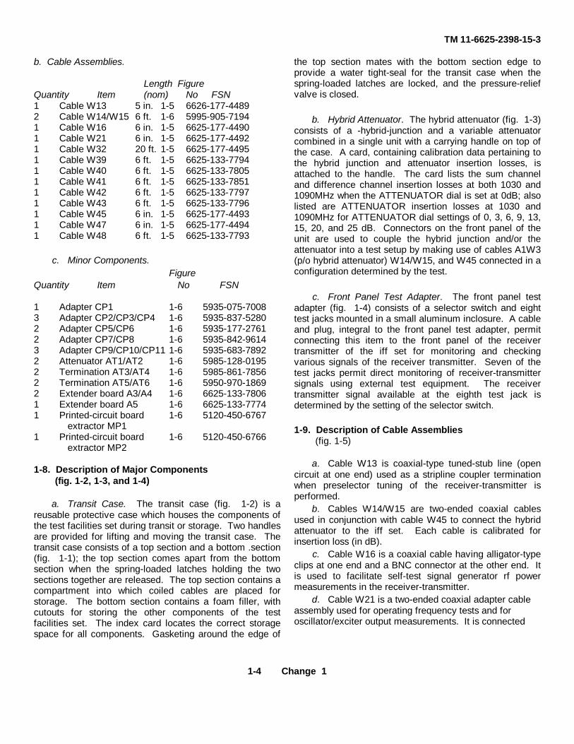
b. Cable Assemblies.
Length FigureQuantity Item (nom) No FSN1 Cable W13 5 in. 1-5 6626-177-44892 Cable W14/W15 6 ft. 1-6 5995-905-71941 Cable W16 6 in. 1-5 6625-177-44901 Cable W21 6 in. 1-5 6625-177-44921 Cable W32 20 ft. 1-5 6625-177-44951 Cable W39 6 ft. 1-5 6625-133-77941 Cable W40 6 ft. 1-5 6625-133-78051 Cable W41 6 ft. 1-5 6625-133-78511 Cable W42 6 ft. 1-5 6625-133-77971 Cable W43 6 ft. 1-5 6625-133-77961 Cable W45 6 in. 1-5 6625-177-44931 Cable W47 6 in. 1-5 6625-177-44941 Cable W48 6 ft. 1-5 6625-133-7793
c. Minor Components.Figure
Quantity Item No FSN
1 Adapter CP1 1-6 5935-075-70083 Adapter CP2/CP3/CP4 1-6 5935-837-52802 Adapter CP5/CP6 1-6 5935-177-27612 Adapter CP7/CP8 1-6 5935-842-96143 Adapter CP9/CP10/CP11 1-6 5935-683-78922 Attenuator AT1/AT2 1-6 5985-128-01952 Termination AT3/AT4 1-6 5985-861-78562 Termination AT5/AT6 1-6 5950-970-18692 Extender board A3/A4 1-6 6625-133-78061 Extender board A5 1-6 6625-133-77741 Printed-circuit board 1-6 5120-450-6767
extractor MP11 Printed-circuit board 1-6 5120-450-6766
extractor MP2
1-8. Description of Major Components(fig. 1-2, 1-3, and 1-4)
a. Transit Case. The transit case (fig. 1-2) is areusable protective case which houses the components ofthe test facilities set during transit or storage. Two handlesare provided for lifting and moving the transit case. Thetransit case consists of a top section and a bottom .section(fig. 1-1); the top section comes apart from the bottomsection when the spring-loaded latches holding the twosections together are released. The top section contains acompartment into which coiled cables are placed forstorage. The bottom section contains a foam filler, withcutouts for storing the other components of the testfacilities set. The index card locates the correct storagespace for all components. Gasketing around the edge of
the top section mates with the bottom section edge toprovide a water tight-seal for the transit case when thespring-loaded latches are locked, and the pressure-reliefvalve is closed.
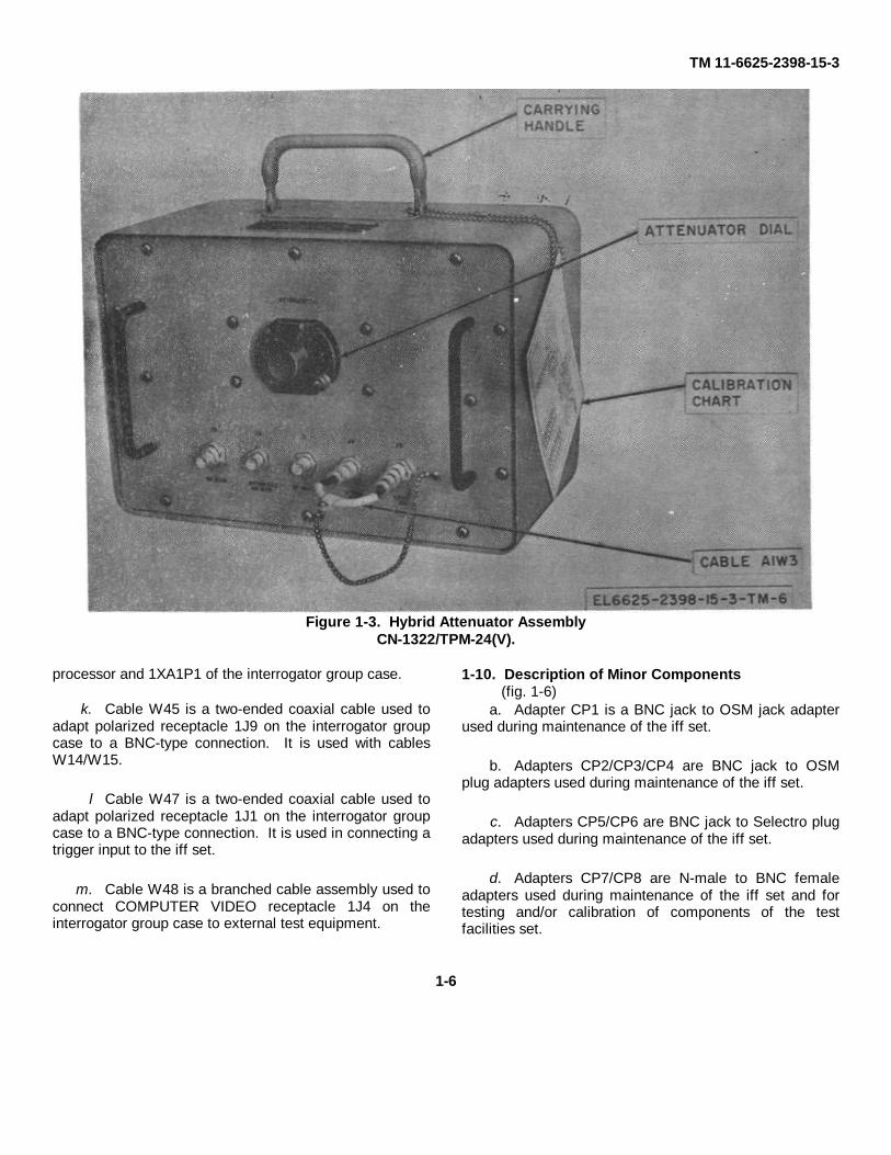
b. Hybrid Attenuator. The hybrid attenuator (fig. 1-3)consists of a -hybrid-junction and a variable attenuatorcombined in a single unit with a carrying handle on top ofthe case. A card, containing calibration data pertaining tothe hybrid junction and attenuator insertion losses, isattached to the handle. The card lists the sum channeland difference channel insertion losses at both 1030 and1090MHz when the ATTENUATOR dial is set at 0dB; alsolisted are ATTENUATOR insertion losses at 1030 and1090MHz for ATTENUATOR dial settings of 0, 3, 6, 9, 13,15, 20, and 25 dB. Connectors on the front panel of theunit are used to couple the hybrid junction and/or theattenuator into a test setup by making use of cables A1W3(p/o hybrid attenuator) W14/W15, and W45 connected in aconfiguration determined by the test.
c. Front Panel Test Adapter. The front panel testadapter (fig. 1-4) consists of a selector switch and eighttest jacks mounted in a small aluminum inclosure. A cableand plug, integral to the front panel test adapter, permitconnecting this item to the front panel of the receivertransmitter of the iff set for monitoring and checkingvarious signals of the receiver transmitter. Seven of thetest jacks permit direct monitoring of receiver-transmittersignals using external test equipment. The receivertransmitter signal available at the eighth test jack isdetermined by the setting of the selector switch.
1-9. Description of Cable Assemblies(fig. 1-5)
a. Cable W13 is coaxial-type tuned-stub line (opencircuit at one end) used as a stripline coupler terminationwhen preselector tuning of the receiver-transmitter isperformed.
b. Cables W14/W15 are two-ended coaxial cablesused in conjunction with cable W45 to connect the hybridattenuator to the iff set. Each cable is calibrated forinsertion loss (in dB).
c. Cable W16 is a coaxial cable having alligator-typeclips at one end and a BNC connector at the other end. Itis used to facilitate self-test signal generator rf powermeasurements in the receiver-transmitter.
d. Cable W21 is a two-ended coaxial adapter cableassembly used for operating frequency tests and foroscillator/exciter output measurements. It is connected
1-4 Change 1

TM 11-6625-2398-15-3
Figure 1-2. Case, Test Facilities Set CY-6825/TPM-24(v) 3
to 1A3A1A3A4 as shown in TM 11-5895-687-35-4 figure18-5.
e. Cable W: 32 is a two-ended power cable having amulti-pin plug at one end for connection to the powerinput receptacle on the iff set interrogator group case; theother end of the cable has a polarized power plug toconnect to an external source of power.
f. Cable W39 is a branched-type multiconductorcable assembly used in conjunction with cable W40 toextend the receiver-transmitter of the iff set from theinterrogator group case. Cable W39 connects betweenlA3P1 of the receiver-transmitter and 1XA3P1 of theinterrogator group case. Two break-out coaxial cables inthe branched section of the cable assembly areconnected together by means of adapter couplers. Thesetwo break-out cables are calibrated for insertion loss (indB) and may be uncoupled for use with external testequipment.
g. Cable W40 is a two-ended multiconductor cableassembly used in conjunction with cable W39 to extend
the receiver-transmitter of the iff set from the interrogatorgroup case. Cable W40 connects between 1A3P2 of thereceiver transmitter and 1XA3P2 of the interrogator groupcase.
h. Cable W41 is a two-ended multiconductor cableassembly used in conjunction with cable W42 to extendthe synchronizer of the iff set from the interrogator groupcase. Cable W41 connects between 1A2P1 of thesynchronizer and 1XA2Pl of the interrogator group case.
i. Cable W42 is a two-ended multiconductor cableassembly used in conjunction with cable W41 to extendthe synchronizer of the iff set from the interrogator groupcase. Cable W42 connects between 1A2P2 of thesynchronizer and 1XA2P2 of the interrogator group case.
j. Cable W43 is a two-ended multiconductor cableassembly used to extend the processor of the iff set fromthe interrogator group case. Cable W43 connectsbetween 1A1P1 of the
1-5
TM 11-6625-2398-15-3
Figure 1-3. Hybrid Attenuator AssemblyCN-1322/TPM-24(V).
processor and 1XA1P1 of the interrogator group case.
k. Cable W45 is a two-ended coaxial cable used toadapt polarized receptacle 1J9 on the interrogator groupcase to a BNC-type connection. It is used with cablesW14/W15.
l Cable W47 is a two-ended coaxial cable used toadapt polarized receptacle 1J1 on the interrogator groupcase to a BNC-type connection. It is used in connecting atrigger input to the iff set.
m. Cable W48 is a branched cable assembly used toconnect COMPUTER VIDEO receptacle 1J4 on theinterrogator group case to external test equipment.
1-10. Description of Minor Components(fig. 1-6)
a. Adapter CP1 is a BNC jack to OSM jack adapterused during maintenance of the iff set.
b. Adapters CP2/CP3/CP4 are BNC jack to OSMplug adapters used during maintenance of the iff set.
c. Adapters CP5/CP6 are BNC jack to Selectro plugadapters used during maintenance of the iff set.
d. Adapters CP7/CP8 are N-male to BNC femaleadapters used during maintenance of the iff set and fortesting and/or calibration of components of the testfacilities set.
1-6

TM 11-6625-2398-15-3
Figure 1-4. Adapter. Test MX-8565/ TPM-24(V).
e. Adapters CP9/CP10/CP11 are BNC-type T-connectors used during maintenance of the iff set.
f. Attenuators AT1/AT2 are fixed 6-dB, 50ohm,coaxial N-type attenuators used for testing and/orcalibration of components of the test facilities set.
g. Extender boards A3/A4 are used to makeaccessible for maintenance all printed-circuit boards inthe synchronizer and processor. and printed-circuitboards 1A3A1A1 and 1A3A2A1 in the receiver-transmitter.
h. Extender board A5 is used to make accessible formaintenance printed-circuit boards 1A3A3A2A3,
1A3A3A2A4, and 1A3A3A2A5 in the receiver-transmitter.
i. Printed-circuit board extractors MP1 and MP2provide an efficient means of removing printed-circuitboards from the iff set assemblies.
j. Terminations AT3/AT4 are 50-ohm, 2 watt,coaxial BNC-type, dummy loads used as low power rftermination during maintenance of the iff set and fortesting and/or calibration of the hybrid attenuator.
k. Terminations AT5/AT6 are 75-ohm, 1/2 watt,coaxial BNC-type, dummy loads used as videoterminations during maintenance of the iff set.
1-7
TM 11-6625-2398-15-3
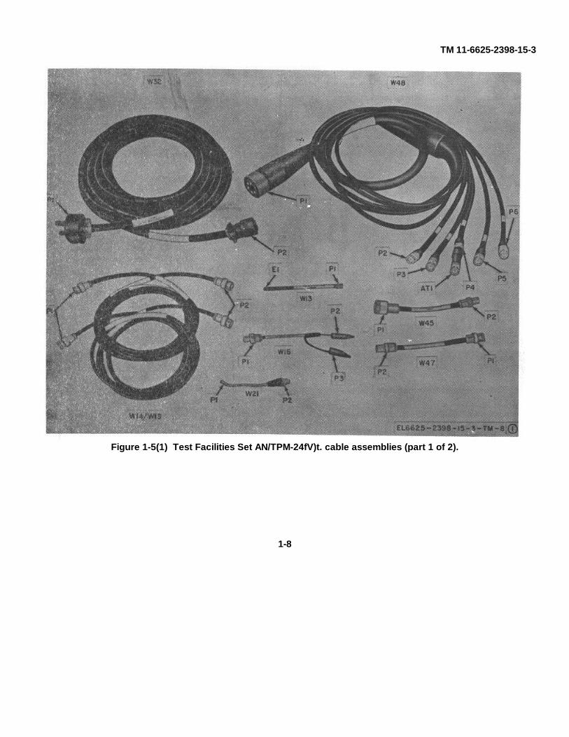
Figure 1-5(1) Test Facilities Set AN/TPM-24fV)t. cable assemblies (part 1 of 2).
1-8

TM 11-6625-2398-15-3
Figure 1-5 (2) Test Facilities Set AN/TPM-24(V)3,cable assemblies (part 2 of 2).
1-9

TM 11-6625-2398-15-3
Figure 1-6(1) Test Facilities Set AN/TPM-24(V)3,minor components (part 1 of 2).
1-10

TM 11-6625-2398-15-3
Figure 1-6 (2) Test Facilities Set AN/TPM-24(V)3,minor components (part 2 of 2).
1-11

TM 11-6625-2398-15-3CHAPTER 2
INSTALLATION
2-1. Unpackinga. Packaging Data. When packed for shipment, the
complete test facilities set is placed in a polyethylenewrap and packed in a single carton which is then sealed.Figure 2-1 illustrates the method employed in packingthe test facilities set. The dimensions of the shippingcontainer are 22 ¾ by 21 ½ by 20 ½ A inches,. and itsvolume is 5.72 cubic feet. The test facilities set whenpackaged weighs approximately 85 pounds.
b. Removing Contents.
(1) Cut the seal and fold back the carton cover.
(2) Remove the polyethylene wrapped transitcase.
(3) Open the polyethylene wrap and remove thetransit case.
(4) Open the transit case and inspect the humidityindicator (should be blue). If the humidity indicator ispink, inspect components for moisture damage.
2-2. Checking Unpacked Equipment
a. Inspect the equipment for damage incurred duringshipment. If the equipment has been damaged, reportthe damage on DD Form 6 (para 1-3).
b. See that the equipment is complete as listed onthe packing slip. If a packing slip is not available, checkthe equipment against the basic issue items list (app III).Report all discrepancies in accordance with TM 38-750.Shortage of a minor assembly or part that does notaffect proper functioning of the equipment should notprevent use of the equipment.
c. If the equipment has been used or reconditioned,see whether it has been changed by a
modification work order (MWO). If the equipment hasbeen modified, the MWO number will appear on thefront panel near the nomenclature plate. If modified,see that any operational instruction changes resultingfrom the modification have been entered in theequipment manual.
NOTECurrent MWO's applicable to theequipment are listed in DA Pam :310-7.
2-3. Installation and Connections
a. Installation. The test facilities set is used inconjunction with a fully operational iff set and externaltest equipment in the test-bench maintenance of iff setsreturned from using organizations. Since the testfacilities set primarily contains special purpose testaccessories, only those components and cables of thetest facilities set pertinent to the particular maintenanceto be performed need to be installed at any one time. Ingeneral, when bench testing of the IFF set or its majorcomponents is to he performed, sufficient space mustbe provided on or near the test bench to accommodatethe transit case, the external test equipment, the iff setgroup case, any components of the IFF set removedfrom the group case, and all required interconnectingcabling.
b. Connections. As noted in paragraph a above,only those cables of the test facilities set required for aparticular maintenance operation need to be connectedat any one time. If extended and/or extensive use of thetest facilities set is anticipated, however, it may bedesirable to set up a basic test station. Whenconnections are made as indicated in the followingchart, a basic test station for iff set system testingresults. This station may be expanded upon, using theinformation contained in chapter 3 and in themaintenance manuals for the iff set and its majorcomponents, to obtain the proper connections forparticular maintenance procedures.
2-1

TM 11-6625-2398-15-3
Figure 2-1. Packaging of Test Facilities Set AN/TPM-24(V)3.
Cable Required LengthNo. No. (ft) Connects
From To
W39 1 6 1XA3P1 of interrogator 1A3P1 of receiver- trans-group ease mitter
W40 1 6 1XA3P2 of interrogator 1A3P2 of receiver-trans-group case mitter
W41 1 6 1XA2P1 of interrogator 1A2P2 of synchronizergroup case
W42 1 6 1XA2P2 of interrogator 1A2P2 of synchronizergroup case
W43 1 6 1XA1P1 of interrogator 1A1P1 of processorgroup case
2-2

TM 11-6625-2398-15-3Cable Required LengthNo. No. (ft) Connects
From To
W47 1 1/2 1J1 of interrogator group Cable to external triggercase source (not supplied)
W1a 1 7 2/3 1J5 of interrogator group W1 of control boxcase
W32b 1 20 1J7 of interrogator group Dc power sourcecase
a Cable W1 is supplied with the iff set.b Caution. To avoid damage to, the equipment under test, initially check that the polarity of the d-c on the power receptacle agrees
with the, polarity shown for cable W:32 on figure 6-10. DO NOT plug in cable W32 if the polarity is incorrect.
2-3

TM 11-6625-2398-15-3CHAPTER 3
OPERATING INSTRUCTIONS
Section I. OPERATOR'S CONTROLS AND CONNECTORS
3-1. Hybrid Attenuator Al, Operating Control,Connectors and Cable(fig. 3-1)
Control or cable connector FunctionATTENUATOR control Provides continuously variable
AT1( variable attenuator) control of the attenuationbetween ATTEN OUT jackJ4 and ATTEN 1N/RF DIFFjack J5 from 0 to 25dB
ATTEN IN RF DIFF jack Permits connection of externalJ5 equipment to ATTENUA-
TOR AT1.ATTEN OUT jack J4 Permits connection of ex-
ternal equipment or the hy-brid junction of the hybridattenuator to ATTENUA-TOR AT1.
Cable W3 Permits series connection ofATTENUATOR AT1 andthe hybrid junction by interconnecting ATTEN OUTjack J4 and CPLR IN jackJ3
RF IN OUT JACK J1 Permits connection of exter-nal equipment to the hybridjunction. When used as aninput connection, rf signalsapplied at this jack areequally split and appear inattenuated from (approxi-mately 6dB down) at bothRF SUM jack J2 and CPLRIN jack J3. When used asan output connection, rf sig-nals applied at either RFSUM jack J2 or CPLR INjack J3 appear in attenu-ated from (approximately6dB down) at this jack.
RF SUM jack J2 Permits connection of exter-nal equipment to the hybridjunction. When used as aninput connection, rf signalsapplied at this jack appear
(less insertion loss of thecables and hybrid junction)at RF IN/OUT jack J1. Mayalso be used as an outputconnection when rf signalsare applied at RF IN/OUTjack J1 (see above).
CPLR IN jack J3 Permits connection of exter-nal equipment or ATTENU-ATOR AT1 (via A1W3) tothe hybrid junction. Whenused as an input connection,rf signals applied at thisjack appear (less insertionlosses ) at RF IN/OUT jackJ1. May also be used as anoutput connection when rfsignals are applied at RFIN/OUT jack J1 (see above).
3-2. Front Panel Test Adapter A2, OperatingControl and Connector
(fig. 3-2)Control or cable connector Function
Plug P1 Connects front panel testadapter to TEST connector1A3J1 on the front panelof the receiver-transmitter.
VIDEO switch S1 Selects various signals of thereceiver-transmitter formonitoring at VIDEO jackJ1 as follows:
Position Signal
RETURN +28 vdc return(GND) (system
ground)ISLS GATE Isls gate inputCHAL Challenge vi-
VIDEO deo inputSUM IF Detected sum
VIDEO channel replay video
3-1

TM 11-6625-2398-15-3
Figure 3-1. Hybrid attenuator A1, operating control, connectors and cable.
Control or connector FunctionDIFF IF Detected dif-
VIDEO ferencechannel re-
MOD PULSE Modulationpulses
RCVR VIDEO Receiver videooutput
CHAL MON Detected inci-DET INCI dent (trnas-DENT PWR mitted) pow-
er pulsesCHAL MON Detected re-
Control or connector FunctionDET REFL flected pow-PWR er pulses
VIDEO jack J1 Permits monitoring of variousreceiver-transmitter signalsas selected by VIDEOswitch S1
RT VAULT jack J2 Permits monitoring of thefault enable output of thereceiver-transmitter.
LVPS MON jack J3 Permits monitoring of the lowvoltage power supply monitor signal of the receiver-transmitter.
3-2

TM 11-6625-2398-15-3
Control or connector Function
CHAL MON ENABLE jack Permits monitoring of theJ4 challenge monitor enable
output of the receiver-trans-mitter.
SUM XTAL INHIBIT jack J6 Permits monitoring of the sumchannel crystal (mixeddiode) current signal of thereceiver-transmitter.
ISLS INHIBIT jack 6 Permits monitoring of the isls
Control or connector Function
inhibit pulse output of thereceiver-transmitter.
DIFF XTAL CUR jack J7 Permits monitoring of the diference channel crystal(mixer diode) current signalof the receiver-transmitter.
GND jack J8 Provides the ground returnfor the signal being moni-tored.
Section II. OPERATION
3-3. Types of Operation
a. The test facilities set is used to interconnectcomponents of the IFF set and to facilitate monitoring ofsignals and voltages when the iff set and/or itscomponents are undergoing test bench maintenance.Depending on the availability of bench space and theexpected maintenance workload at a particularmaintenance activity, the test facilities set andassociated required equipment may be installed andconnected as a semi-permanent test station (para 2-3),or only those applicable components required for theparticular maintenance task may be set up.
b. Specific instructions for connecting the IFF setand required test equipment and accessories, and forperforming maintenance on the various iff setcomponents are contained in the technical manualslisted below. General instructions for
operation of the test facilities set are contained inparagraphs 3-4 through 3-11.
IFF set component Technical manual
Control box TM 11-5895-687-35-1Interrogator group case TM 11-5895-687-35-1Processor TM 11-5895-687-35-2Receiver-Transmitter TM 11-5895-687-35-4Synchronizer TM 11-5895-687-35-3
3-4. Connection of Extender Cables
Regardless of the type of operation of the test facilitiesset (para 3-3), it is generally necessary to remove oneor more of the iff set components from the interrogatorgroup case to obtain access for maintenance. CablesW39, W40, W41, W42 and W43 are provided to extendthe processor, synchronizer and receiver-transmitterfrom the interrogator group case. To connect theextender cables, first remove the component(s) from theinterrogator group case as
Figure 3-2. Front panel test adapter A2 operating control connectors.
3-3

TM 11-6625-2398-15-3
described in a, below, and then make the appropriateconnections using the information in b, below.
a. Component Removal
(1) Loosen the captive screws securing thecomponent front panel to the interrogator groupcase.
(2) Grasp the handles on the front panel of
the component and slide the component from the groupcase until the slide locks on the chassis slide engage.
(3) Depress the chassis slide locks and removethe component from the interrogator group case.
b. Cable Connections (fig. 3-3).
From ToComponents Connector Connector Cable Connector Connector Component
Processor 1A1P1 P1 W43 P2 1XA1P1 Interrogator group caseSynchronizer 1A2P1 P1 W41 P2 1XA2P1 Interrogator group caseSynchronizer 1A2P2 P1 W42 P2 1XA2P2 Interrogator group caseReceiver-transmitter 1A3P1 P1 W393 P2 1XA3P1 Interrogator group caseReceiver-transmitter 1A3P2 P1 W40 P2 1XA3P2 Interrogator group case
a Continuity of two of the conductors of cable W39 is provided through plug coupler-plug connections. When plug P3 is disconnected from couplerCP2 the rf isls pulse output of the receiver transmitter is available for monitoring at BNC plug P3. When plug P4 is disconnected from coupler CP2the difference channel rf input to the receiver-transmitter is available for monitoring at BNC plug P4. When plug P5 is disconnected from coupler CP1,the rf challenge pulse output of the receiver-transmitter is available for monitoring at BNC plug P5, and when plug P6 is disconnected from couplerCP1, the sum channel rf input to the receiver-transmitter is available for monitoring at BNC plug P6.
3-5. Connection of Input Power and AdapterCables
Cables W32 and W47 (fig. 3-3) are provided to connectinput power and an input trigger to the interrogator groupcase. Connect P1 of cable W47 to PRETRIG connector1J1 on the rear of the interrogator group case. Connect1P2 of sable W47 via a 75-ohm video cable, such asCG-530B U (P O AN, UPM-98), to the trigger source.
CAUTIONTo avoid damage to the equipment undertest, initially check that the polarity of the dcon the power receptacle agrees with thepolarity shown for cable W32 on figure 6-10.DO NOT plug in cable W: 32 if the polarity isincorrect.
Connect P1 of cable W32 to POWER connector 1J7 onthe rear of the interrogator group case, and connect P2of cable W32 to a source of 28 volts dc.
3-6. Use of Cable W13
Cable W13 is provided for use during preselectoralignment of the receiver circuits of the receiver-transmitter. As part of this alignment, which isperformed with the receiver-transmitter deenergized, a1090MHz signal from external test
equipment is applied to stripline coupler connector A1J1of receiver 1A3A3A1, and various coupling probes andresonator tuning clips of the receiver assembly areadjusted for the proper response characteristics. (SeeTM 11-5895-687-35-4.) Stripline coupler connectorA1J1, however, is directly coupled to stripline couplerconnector A1J2, which must be terminated with cableW13 to simulate the characteristics of the cavityamplifiers of the transmitting circuits of the receiver-transmitter connected to this point during normaloperation. Before performing preselector alignment,connect P1 of cable W13 to connector 1A3A3A1A1J2 ofthe receiver-transmitter.
3-7. Use of Cable W16
Cable W16 is provided for use during alignment of theself-test signal generator of the self-test circuits of thereceiver-transmitter. As part of this alignment, theoutput power at terminal 4 of self-test signal generatorboard 1A3A3A1A2 is monitored using an external powermeter, and various tuning coils and capacitors areadjusted for maximum power output. See TM 11-5895-687-35-4 for the detailed procedure of this' alignment.
3-8. Connection of Cable W48
Cable W48 (fig. 3-3) is provided to connect Test Set-Simulator, Transponder AN/APM-245 and
3-4

TM 11-6625-2398-15-3
Figure 3-3. Connections of test cables to the IFF set.
other external test equipment to the interrogator groupcase. To establish initial test set-up connections usingthe AN/APM-245, connect P1 of cable W48 toCOMPUTER VIDEO jack 1J4 on the rear of theinterrogator group case. Connect P1, P4, and P5 ofcable W48 to the EXTERNAL TRIGGER, TEST WORD,and DIS PARITY connectors respectively, on theAN/APM-245. Connectors P2 and P6 of cable W48may be used for monitoring the mode 4 reply output ofthe iff set and applying a simulated mode 4 timedecoded video signal input to the iff set, respectively,using external test equipment. Refer to TM 11-5895-687-35-3 for detailed connections of W48 andprocedures for use of
the AN/APM-245.
3-9. Operation of Front Panel Test Adapter
The front panel test adapter is provided to facilitatemonitoring of various signals of the receiver-transmitter.Signals available at multipin TEST connector 1A3J1 ofthe receiver-transmitter are either routed directly toindividually labeled test jacks on the front panel testadapter, or are routed through the VIDEO selectorswitch to the VIDEO jack. To operate the front paneltest adapter, proceed as follows:
a. Connect P1 of the front panel test adapter cableto TEST connector 1A3J1 on the front
3-5

TM 11-6625-2398-15-3
panel of the receiver-transmitter.
b. To monitor signals at the individually labeled testjacks, connect the appropriate external test equipment(e.g., multimeter, differential voltmeter etc.) to the testjack of interest and to GND test jack J8 on the frontpanel test adapter, and observe the reading on theexternal test equipment.
c. To monitor signals at the VIDEO jack, connect anoscilloscope to the VIDEO jack using a high impedanceprobe (Test Probe MX-2817/U or equivalent, refer to TM11-6625-535-15), ground the probe to GND jack J8,select the signal of interest on the VIDEO switch, andobserve the signal on the oscilloscope.
3-10. Operation of Hybrid Attenuator
The hybrid attenuator is provided to facilitate testing,troubleshooting and alignment/adjustment of thereceiver-transmitter in the iff set. All of the specific usesof the hybrid attenuator with the receiver-transmitter aredescribed in TM 11-5895-687-35-4. Operation of thehybrid attenuator as an attenuator (a below) and intypical receiver and transmitter test configurations (bbelow) are as follows:
a. Challenge Monitor Test. The attenuator portion ofthe hybrid attenuator is used to attenuate the poweroutput of the transmitter in the iff set before it reachesthe if strip line coupler (1A3A5) to determine if thechallenge monitor indicator is operating within theprescribed limits. Refer to TM 11-5895-687-35-4 for thedetailed procedure of this test.
b. Typical Hybrid Attenuator Receiver andTransmitter Test Configurations.
(1) The test connections between the iff set andthe hybrid attenuator, shown in figure 3-4, are typical formost of the receiver and transmitter tests on the iff set.Consult the individual test procedure in the TM 11-5895-687-35-4 for possible deviations in the testconnections and for prescribed settings of theATTENUATOR control.
(2) Cable W45 and adapter CP7/CP8 enableconnection of cables W14/W15 from the hybridattenuator to the RF sum (J9) and RF difference (J10)channels, respectively.
CAUTIONTo avoid damage to the equipment under testDO NOT energize Interrogator Set AN/TPX-50before terminating jacks J9 and J10. If testingwithout the hybrid attenuator, terminate cableW45 and adapter CP7/CP8 with terminationsAT3/AT4.
(3) The insertion losses marked on the tags attachedto the hybrid attenuator and connecting coaxial cables(e.g., W14/W15 and/or W39) have to be taken intoconsideration when figuring the attenuation in dB forsetting the ATTENUATOR control.
3-11. Typical Connection and Use of MinorComponents
Certain of the minor components of the test facilities setare standard general-purpose adapters and terminationswhich are used in a large number of the test set-upsrequired in maintaining the complete iff set. Included inthis category are adapter CP7/CP8 (N-male to BNCfemale adapter, type UG-201A/U), adapter CP9/CP10/CP11 (BNC tee, type UG-274B/U), terminationAT3/AT4 (50-ohm dummy load, type DA-558), andtermination AT5/AT6 (75-ohm dummy load, type DA-559). General instructions for connecting the remainingminor components of the test facilities set are providedbelow.
a. Extender Boards and Printed Circuit BoardExtractors
(1) Printed circuit (pc) board extractor MP2 isused to remove any pc board in the processor orsynchronizer assembly of the iff set or pc boards1A3A1A1 and 1A3A2A1 of the receiver-transmitterassembly. Remove power from the iff set. Remove thechassis and release the retaining cover on the module.Insert the tines of MP2 into the holes at the top of the pcboard and pull out the board.
(2) Printed circuit board extractor MP1 is used toremove pc boards 1A3A3A2A3, 1A3A3A2A4 or1A3A3A2A4 of the receiver-transmitter assembly in theiff set. Remove these pc boards as described in (1)above.
(3) Extender boards A3/A4 provide maintenanceaccessibility for the pc boards removed by pc boardextractor MP2, (1) above. Remove the pc board andinsert the extender board in
3-6

TM 11-6625-2398-15-3
the connector for the removed board with the evennumbered side of the extender board oriented with thecomponent sides of the pc boards in the balance of theassembly. Orient the component side of the removed
pc board with the even numbered side of the extenderboard and insert the etched terminals in the connector ofthe extender board.
Figure 3-4. Typical hybrid attenuator receiver andtransmitter test connections.
(4) Extender boards A3/A4 are provided with testpoints for each etched terminal of the pc board tofacilitate checking any input or output of the pc board.The numbers (1 through 44) above the test pointcorrespond to the. etched terminal number of the pcboard.
(5) Extended board A5 provides maintenanceaccessibility for the pc boards removed by pc boardextractor MP1, (2) above. Orient the male connectorpins of extender board A5 (printed land side down) withthe top of the receiver-transmitter assembly. Removethe pc board and insert the female pin connector end ofthe extender board in the connector for the removedboard. Orient the component side of the removed pcboard with the top of the receiver-transmitter assembly.Insert the sides of the pc board in the slots of A5 andengage the female connector pins of the pc board withthe male connector pins of the extender board.
b. Adapters CPI and CP2/CP3/CP4. Adapter CP1permits connection of an OSM type plug to a BNC typeplug. Adapters CP2/CP: I/C1'4 permit connection ofOSM type jacks to BNC type plugs. Typical connectionof these adapters is given in the challenge monitor testI)provided in TM 11-5895-687-35-4.
c. Adapters CP5/CP6. Adapters CPS/(CP6 permitconnection of selectro jacks to BNC type plugs. Typicalconnection of these adapters is given in the transmitterfrequency measurement tests provided in TM 11-5895-687-35-4.
d. Attenuators AT1/A72. Attenuators AT1/ AT2 aregeneral purpose 50-ohm 6dB attenuators. Together withother uses they can provide isolation during diplexeradjustment. Typical connection of these attenuators ,Dprovided in TM 11-5895-687-35-4.
3-7

CHAPTER 4OPERATOR'S AND ORGANIZATIONAL MAINTENANCE
4-1. Scope of Maintenance
The maintenance duties assigned to the operator and/ororganizational maintenance mechanic of the testfacilities set are listed below, together with thereferences to the paragraphs covering the specificmaintenance function. These duties do not requirespecial tools or test equipment.
a. Weekly preventive checks and: services (para 4-5).
b. Quarterly preventive checks and services (para 4-6).
c. Cleaning (para 4-7).
d. Troubleshooting (para 4-9).
e. Repairs and adjustments (para 4-10).
4-2. Tools, Materials, and Test Equipment Required
A list of parts authorized for operator's andorganizational maintenance appears in appendix III.The tools, materials, and test equipment required foroperator's and organizational maintenance are listedbelow:
a. ToolsCommon name Equipment Technical manualTool kit Electronic equipment
Tool Kit TK-100G _______b. Materials.
Cleaning compound (FSN 7930-395-9542)
Inhibisol cleaning solvent
Cleaning cloth
Isopropyl alcohol
Camel-hair brush
Fine sandpaper
Light gray enamel paint (gloss)
Light gray enamel paint (semi-gloss)
Rubber tape
Friction tape
c. Test Equipment.
Common name Equipment Technical manual
Multimeter Multimeter AN TM 11-6625-475-10PSM-6B
4-3. Preventive Maintenance
Preventive maintenance is the systematic care,servicing, and inspection of equipment to prevent theoccurrence of trouble, to reduce downtime, and toassure that the equipment is serviceable.
a. Systematic Care. The procedures given inparagraphs 4-5 through 4-8 cover routine systematiccare and cleaning essential to proper upkeep andoperation of the equipment.
b. Preventive Maintenance Checks and Services.The preventive maintenance checks and services charts(para 4-5 and 4-6) outline the functions to be performedat specific intervals. These checks and services are tomaintain the equipment in a serviceable condition. Toassist in maintaining serviceability, the charts indicatewhat to check, how to check, and what the normalconditions are; the References column lists theillustration, paragraph, or TM that contain repair orreplacement procedures. If the defect cannot beremedied by performing the correct
4-1

TM 11-6625-2398-15-3
tive actions indicated, higher category maintenance orrepair is required. Records and reports of these checksand services must be made in accordance with therequirements set forth in TM 38-750.
4-4. Preventive Maintenance Checks and ServicesPeriods
Preventive maintenance checks and services for thetest facilities set are required weekly and quarterly.
a. Paragraph 4-5 specifies checks and services thatmust be accomplished weekly and under the conditionslisted below:
(1) When the equipment is initially installed.
(2) At least once each month if the equipment isnot used periodically.
b. Paragraph 4-6 specifies checks and services thatmust be performed on a quarterly basis.
4-5. Weekly Preventive Maintenance Checks andServices Chart
Sequence Item Procedure ReferencesNo.
1 Completeness Check all components of the test facilities set against the para 1-7list of components supplied; give particular attention tosmall components.
2 Exterior surfaces Clean the transit case exterior with a clean, lint-free cloth para 4-7containing cleaning compound, Fed. Stock No. 7930-395-9542 (or equivalent), to remove accumulated oil film ordust. Then, dry all surfaces thoroughly with a clean lint-free cloth. Inspect all painted surfaces for spots, chips, para 4-8cracks, and corrosion. Touch up or refinish the surfaceas required.
3 Connectors and adapt- a. Check for broken pins, and replace connectors where a. Higher categoryers necessary. maintenance required.
b. Clean dirt from all contacts. b. para 4-7.4 Extender boards a. Check for broken or bent pins and for cracks in the board. a. Higher category.
maintenance required.b. Replace all damaged extender boards, clean dirt from b. para 4-7.
electrical contacts.5 Cables Check for cuts, kinks and breaks. Replace all defective para 4-1"(
cables.6 Controls Check controls on hybrid attenuator and front panel test para 4-10(
adapter. Replace defective controls and knobs.7 Handles and latches Inspect handles and latches on the transit case and handles Higher category main-
of the hybrid attenuator. tenance required.8 Operation During operation. be alert to any unusual performance or
condition.
4-6. Quarterly Preventive Maintenance Checksand Services Chart
Sequence Item Procedure, ReferenceNo.1 Publications See that all publications are complete, serviceable, and DA PAM -310-4
current.2 Modifications Check DA PAM :10-4 to determine if new applicable TM 38-750 and DA
MWO's must be applied immediately. All NORMAL PAM 310-4MWO’s must be scheduled.
3 Cleanliness See that equipment is clean. para 4-74 Preservation Check all surfaces for evidence of rust and corrosion. Re- para 4-8
move rust and corrosion and paint bare spots5 Components Check components:
1. Cables for proper mating.2. Smooth operation of ATTENUATOR dial on hybrid
attenuator.3. Extender boards for proper seating in iff set printed
circuit (pc) board connectors.4. Pc board extractors for proper mating in holes of
pc board.6 Calibration 1. Check hybrid attenuator insertion losses. para 6-8 through 6-10
2. Check hybrid attenuator VSWR. para 6-113. Check insertion losses of cables W14/W15 and W39. para 6-12
4-2

TM 11-6625-2398-15-3
4-7. Cleaninga. Transit Case. Inspect the exterior surfaces of the
transit case. The exterior surfaces should be clean, freeof dust, dirt and grease.
(1) Remove dust and loose dirt with a clean, lint-free cloth.
WARNINGCleaning compound is flammable and itsfumes are toxic. Provide adequateventilation. DO NOT use near a flame.
(2) Remove grease, and ground-in dirt from thecomponents. Use a cloth dampened (not wet) withcleaning compound.
(3) Use a brush to remove dust or dirt from plugs,jacks, and knobs.
b. Extender Boards. Periodically clean the extenderboard assemblies with inhibisol cleaning solvent or witha solution of 70 percent isopropyl alcohol and 30 percentdistilled water. Using a brush, clean the printed-circuitcontacts with Miller-Stephenson Freon TF Degreaser.
4-8. Touchup Painting Instructions
Remove rust and corrosion from metal surfaces bylightly sanding them with fine sandpaper. Brush two thincoats of paint (see below) on the bare metal to protect itfrom further corrosion. Refer to applicable cleaning andrefinishing practices specified in TM 9-213 (PaintingInstructions for Field Use). For touchup painting of theTransit Case, use Light Gray Enamel, Formula No. 11per MIL-E-15090, Type II, Class I (Gloss); for touchuppainting of the Hybrid Attenuator Assembly and FrontPanel Test Adapter use Light Gray Enamel, FormulaNo. 11 per MILE-15090, Type II, Class 2 (Semi-gloss).
4-9. General Troubleshooting Information
Troubleshooting this equipment is based upon theoperation of the test facilities set in a hot mock-upconfiguration to operate the iff set. If, in troubleshootingthe iff set, certain components of the test facilities setare defective or suspected of being defective (otherthan cables, extender boards or the front panel testadapter) higher category maintenance is required.Troubleshooting the cables, extender boards and thefront panel test adapter of the test facilities set consists
of continuity checks with a multimeter (para 4-11). Theschematics, in chapter 6 are to be used as a guide indetermining the connections to check for continuity.Any cable found to be defective should be sent to highercategory maintenance for repair.
4-10. Operator's Repairs and Adjustments
a. Minor Repair of Cables. Repair minor cuts incable insulation by covering it first with rubber tape andthen with friction tape. If cable is broken, refer defectivecable to higher category maintenance for repair.
b. Replacement or Adjustment of Knobs.
(1) Replacement. To replace a defective knob,proceed as follows:
(a) Set the knob to its extremecounterclockwise position.
(b) Loosen setscrews on the defective knoband remove the knob from the shaft.
(c) Place a new knob on the hybridattenuator shaft, and line up the zero position on thenew knob with the zero index of the stationary portion.Place a new knob on the switch shaft of the front paneltest adapter, aline the marker of the knob with the first(counterclockwise) switch position.
(d) Tighten setscrews.
(2) Adjustment. To adjust a knob on its shaftproceed as follows:
(a) Tighten the setscrews on the loose knoband turn it to its extreme counterclockwise stop.
(b) Loosen setscrews and line up the zeroposition of the knob with the zero index of the stationaryportion.
(c) Tighten setscrews.
4-11. Continuity Check of Cables, Extender Boards,and Front Panel Test Adapter (fig. 4-1)
Use Multimeter AN/PSM-6B to perform the continuitychecks. All tests are made with the following controlsettings on the multimeter:
4-3

TM 11-6625-2398-15-3
FUNCTION — OHMSRANGE — R X 1
Refer to the referenced schematic diagrams forcomponent wiring.
a. Cable W13 (fig. 6-7). Connect one multimetertest lead to the center conductor of the plug on thecable, and the other test lead to the shell of the plug.The meter must indicate open circuit.
b. Cables W14/W15, W16, W21, W45, and W47 (fig.6-8, 6-9, 6-16, and 6-17).
(1) Connect one multimeter test lead to the centerconductor of either plug, and the other test lead to theshell of the same plug. The meter must indicate opencircuit.
(2) Connect one multimeter test lead to the centerconductor of one plug, and the other test lead to thecenter conductor of the plug on the other end of thecable. The meter must indicate zero ohms (continuity)
(3) Connect one multimeter test lead to the outershell of one plug on the cable, and the other test lead tothe outer shell on the other end of the cable. The metermust indicate zero ohms (continuity).
NOTE
One end of cable W16 has alligator clips. P2is the center conductor connector, and P3 isthe shell connector.
c. Cable W32 (fig. 6-10). Check continuity of thecable wires by progressively connecting the multimetertest leads to the active pins on the plugs at each end ofthe cable. The multimeter must indicate zero ohms(continuity) for both wires.
d. Cable W39 (fig. 6-11). Couplers W39 CP1 andW19 CP2 must be connected on cable W39.
(1) Check individual wire shielding byprogressively connecting the multimeter test leads toeach wire shield pin connection on the plugs at each endof the cable. The meter must indicate zero ohms(continuity) for each shield.
(2) Check for shorting of wires to shields byprogressively connecting the multimeter test
leads to the pin connectors for each wire and to itsshield on a plug at one end of the cable. The metermust indicate open circuit.
(3) Check continuity of cable wires byprogressively connecting the multimeter test leads to theactive pins on the plugs at each end of the cable. Themeter must indicate zero ohms (continuity) for eachwire.
e. Cable W40, W41, W42, and W43. (fig. 6-12through 6-15)
(1) Check that the cable shielding is bonded to theshell of the plugs, by connecting one multimeter testlead to the shell of one plug, and the other test lead tothe shell of the other plug. The meter must indicatezero ohms (continuity).
(2) Repeat d(1).
(3) Repeat d(2).
(4) Repeat d(3).
f. Cable W48 (fig. 6-18). This cable consists of fiveindividual coaxial cables terminated by a multipinconnector on one end.
(1) Check coaxial shielding by progressivelyconnecting the multimeter test leads to each of theshield pins on one end of the cable and to the shell ofthe appropriate coaxial connector on the other end. Themeter must indicate zero ohms (continuity) for eachshield.
(2) Check for shorting of coaxial cables byprogressively connecting the multimeter test leads to thecenter conductor contacts of the multipin connector andthe associated shield connectors for each cable. Themeter must indicate open circuit for each test.
(3) Check continuity of the center coaxialconductors by progressively connecting the multimetertest leads from the center conductor terminals of themultipin connector and the center conductor of theassociated plug at the other end of the cable. Pin E toAT1 will indicate approximately 91 ohms and thebalance of cables must indicate zero ohms (continuity).
g. Extender Boards A3/A4. (fig. 6-21)
(1) Check for short circuits by connecting
4-4
TM 11-6625-2398-15-3
the multimeter test leads to the first two etchedterminals on one side of the board. Move the twomultimeter test leads successively, by advancing eachtest lead one terminal at a time, across the board.Repeat for the etched terminals on the opposite side ofthe board. The meter must indicate open circuit foreach test.
(2) Check board continuity by progressivelyconnecting one multimeter test lead to the etchedterminals at one end of the board, connect the other testlead to the corresponding connector contacts at theopposite end of the board. The meter must read zeroohms (continuity) for each etched terminal.
(3) Check for short circuits by successivelyconnecting the multimeter test leads to etched terminalsback-to-back on opposite sides of the boards. Themeter must indicate open circuit.
(4) Check continuity to test points on the board byconnecting one multimeter test lead to the first contactof J45 and the test point (J1 or J2) immediately below.Advance test leads successively across the board to thelast contact of J45 and the last test point (J43 or J44).Repeat for the opposite side of the board. The metermust indicate zero ohms (continuity) for each test point.
h. Extender Board A5. (fig. 6-22)
(1) Check for short circuits by connecting themultimeter test leads to the first two adjacent pins onone end of the board. Move the two multimeter testleads successively, by advancing each test lead one pinat a time, across the board. The meter must indicateopen circuit for each test.
(2) Check board continuity by progressivelyconnecting the multimeter test leads to thecorresponding pins at each end of the board. The metermust read zero ohms (continuity) for each set of pins.
i. Front Panel Test Adapter. (fig. 6-20)
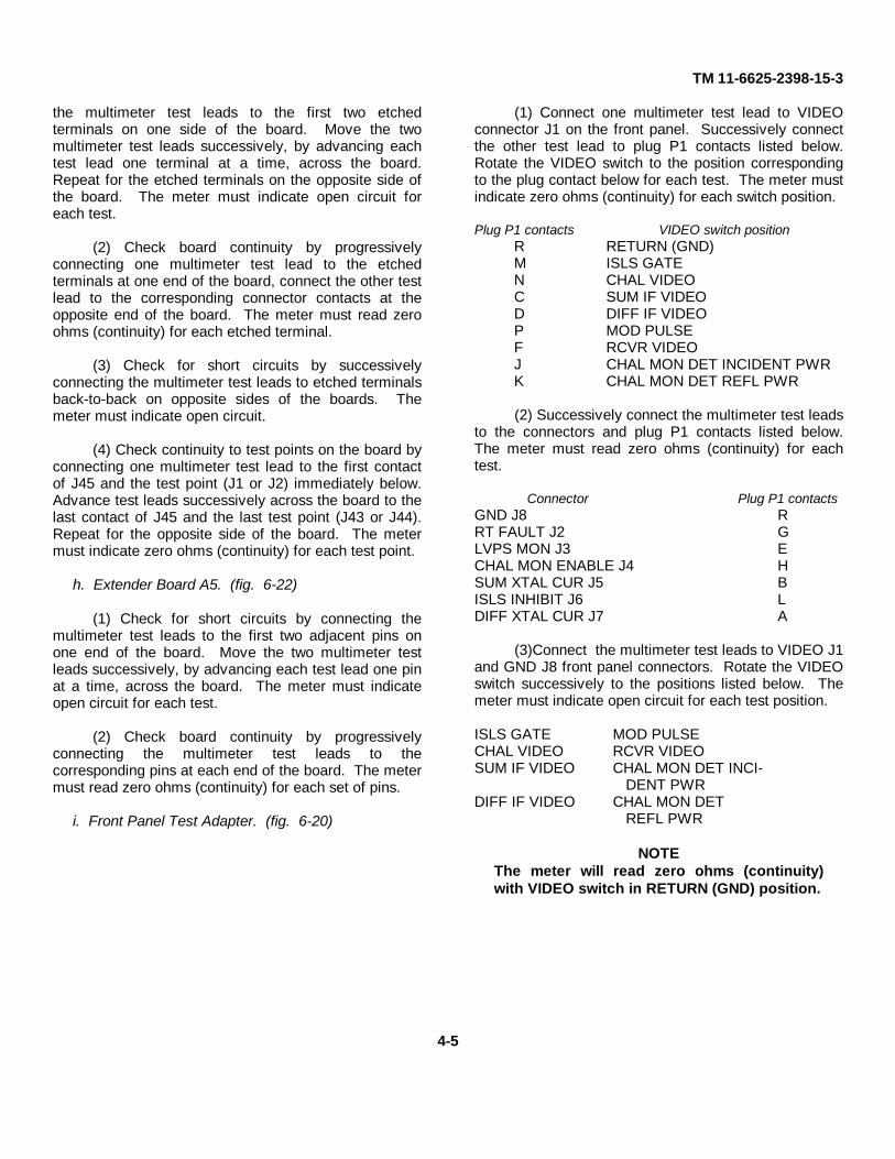
(1) Connect one multimeter test lead to VIDEOconnector J1 on the front panel. Successively connectthe other test lead to plug P1 contacts listed below.Rotate the VIDEO switch to the position correspondingto the plug contact below for each test. The meter mustindicate zero ohms (continuity) for each switch position.
Plug P1 contacts VIDEO switch positionR RETURN (GND)M ISLS GATEN CHAL VIDEOC SUM IF VIDEOD DIFF IF VIDEOP MOD PULSEF RCVR VIDEOJ CHAL MON DET INCIDENT PWRK CHAL MON DET REFL PWR
(2) Successively connect the multimeter test leadsto the connectors and plug P1 contacts listed below.The meter must read zero ohms (continuity) for eachtest.
Connector Plug P1 contactsGND J8 RRT FAULT J2 GLVPS MON J3 ECHAL MON ENABLE J4 HSUM XTAL CUR J5 BISLS INHIBIT J6 LDIFF XTAL CUR J7 A
(3)Connect the multimeter test leads to VIDEO J1and GND J8 front panel connectors. Rotate the VIDEOswitch successively to the positions listed below. Themeter must indicate open circuit for each test position.
ISLS GATE MOD PULSECHAL VIDEO RCVR VIDEOSUM IF VIDEO CHAL MON DET INCI-
DENT PWRDIFF IF VIDEO CHAL MON DET
REFL PWR
NOTEThe meter will read zero ohms (continuity)with VIDEO switch in RETURN (GND) position.
4-5

TM 11-6625-2398-15-3
Figure 4-1. Multimeter test connections.
4-6

TM 11-6625-2398-15-3CHAPTER 5
FUNCTIONING
5-1. General
The functioning of the hybrid attenuator (A1) and cableW13 is described in this chapter. The functioning of thebalance of the components of the test facilities set isself evident.
5-2. Hybrid Attenuator(fig. 6-19)
a. The hybrid attenuator basically consists of twosubassemblies, hybrid coupler (HY1) and variableattenuator (AT1). The hybrid attenuator can he used asan entity to couple rf to or from the iff set and externaltest equipment, or AT1 can be used alone as a variableattenuator.
b. When the hybrid attenuator is used to coupler rf,external cable A1W3 connects attenuator AT1 to hybridcoupler HY1. This permits up to 25dB attenuation ofdifference channel rf, below the sum channel rf, whenperforming receiver testing of the iff set.
5-3. Attenuator AT1
Attenuator AT1 is a two-terminal, non-repairable, wide-band variable attenuator with a direct reading dial. Thedial is calibrated from 0 to 25dBH in 1-dB steps. TheATTEN IN/RF IFF jack (J5) and the ATTEN OUT jack(J4), together with the associated coaxial cabling andconnectors P3 and P2, respectively, make AT1accessible at the front panels.
5-4. Hybrid Coupler HY1
a. Hybrid coupler HY1 is a four-port, 3-dB couplerwhich evenly divides an input signal from external testequipment into isolated quadrature-phased outputs, forreceiver testing of the iff set. Front panel RF IN/OUTjack (J1) provides the input to HY1 and the RF SUM(J2) and CPLR IN (J3) jacks provide the outputs forreceiver testing.
b. The hybrid coupler input signals for iff settransmitter testing are applied via the RF SUM (J2) andCPLR IN (J3) jacks. The hybrid coupler then combinesthe sum and difference rf signals into one resultant rfoutput to external test equipment at the front panel RF.IN/OUT jack (J1).
c. The coupler is symmetrical, signals applied to anyinput port (e.g., HY1J1) will divide equally between theopposite pair of ports (HY1J2 and HY1J3) and theadjacent port (HY1J4) will be isolated. By the sameprinciple, if equal amplitude quadrature-phased signalsare applied to adjacent ports (e.g., HY1J2 and HY1J3)they will combine at one output port (HY1J1) and cancelat the other (HY1J4). Termination AT2 (to HY1J4) is a50 ohm matched load and is provided to minimizereflected signal from port HY1J2.
d. The sum channel overall insertion loss of thehybrid coupler from the RF SUM jack (J2) to the RFIN/OUT jack (J1) is the sum of the losses of W1(approximately 3.75dB), HY1 (3dB) and miscellaneouslosses in J2, CP2, and the coaxial cable terminated byP1 and J1.
e. The difference channel overall insertion loss ofthe hybrid coupler from the CPLR IN jack (J3) to the RFIN/OUT jack (J1) is the sum of the losses of W2(approximately 3.25 dB), HY1 (3dB) and miscellaneouslosses in J3. CPL, and the coaxial cable terminated byP1 ;J1. These losses when added to the losses of W3and the AT1 circuit (para 5-3, with the ATTENUATORcontrol set at 0) are equal to or slightly less than theoverall insertion loss of the sum channel.
5-5. Cable W13(fig. 6-7)
Cable W13 is a nonrepairable, coaxial-type, tuned-stubline (open circuit at one end). It is used as a strip linecoupler termination for con
5-1

TM 11-6625-2398-15-3
nector A1J2 during preselector alignment of thereceiver circuits of the receiver-transmitter. It simulatesthe characteristics of the cavity amplifiers of the
transmitting circuits of the receiver-transmitterconnected to A1J2 during normal operation.
5-2

TM 11-6625-2398-15-3CHAPTER 6
GENERAL SUPPORT MAINTENANCE
Section I. GENERAL TROUBLESHOOTING INFORMATION
WARNING
When using this equipment inconjunction with the iff set, beextremely careful because of highvoltages associated with someassemblies of the IFF set. Consultthe applicable IFF set TM for furtherinformation on circuits that areextremely dangerous.
6-1. General Instructions
Troubleshooting at general support (GS) maintenancelevel includes all the techniques outlined for operator'sand organizational maintenance, and any special oradditional techniques required to isolate a defectivepart. Section II provides troubleshooting procedures tobe used at the GS level. Section III providescomponent testing and calibration techniques.
6-2. Organization of Troubleshooting Procedures
a. General. The three steps in servicing the testfacilities set are:
(1) Sectionalization of the fault
(2) Localization of the fault
(3) Isolation of the fault
b. Sectionalization. The test facilities set consists ofthe components listed in paragraph 1-6. The first step intracing the trouble is to locate the component orcomponents at fault by the following methods:
(1) Visual inspection. The purpose of visualinspection is to locate faults without testing ormeasuring.
(2) Operational. Except for the hybrid attenuatorassembly, troubleshooting is based on the operationaluse of this equipment with an iff set.
c. Localization. In the course of using thisequipment to maintain the iff set, the operational ormaintenance tests called for in the iff set manual maybe used in determining the location of the fault in thetest facilities set (para 6-5).
d. Procedures for isolating troubles in the hybridattenuator assembly are given in paragraph 66.
e. Techniques. In performing the sectionalization,localization, and isolation procedures, the followingtechniques may be applied:
(1) Insulation resistance measurements.
(2) Continuity checks.
6-3. Test Equipment Required
The following chart lists test equipment required fortroubleshooting the test facilities set. The associatedtechnical manuals are also listed.
CAUTIONBe certain that the components of testfacilities set are disconnected from the IFF setbefore performing troubleshooting. The IFFset contains transistors which could bedamaged.
6-1

TM 11-6625-2398-15-3
Common name Test equipment Technical manualMultimeter Multimeter AN/PSM-6B TM 11-6625-475-10Megger Ohmmeter ZM-21A/U TM 11-2050Signal generator Signal Generator SG-.140/G NAVSHIPS 93665SWR indicator Indicator, Standing Wave Ratio AN/ TM 11-6625-335-12
UPM-108AVariable attenuator Variable attenuator, Alfred Elec-
tronics Model E101Slotted line Coaxial Slotted line IM-92, 11 TM 11-5109Crystal detector Crystal Detector. Hewlett-Packard
Co. Model 42:3AFilter Low-Pass Filter, Hewlett-Packard
Co. Model :350CPrinted wiring kit Repair Kit. Printed Wiring Board,
MK-772 UTool Kit Tool Kit. Electronic Equipment Tool
Kit TK-100G50-ohm termination Termination, 50-ohms, Microlab
FXR TA-6MNAdapter Adapter (type N male to type BNC
females ) ,UG-201A UAdapter Adapter N female to type
BNC female).UG-606 UAdapter Adapter (type BNC female). to type
BNC female). UG-914 U
Section II. COMPONENT TROUBLESHOOTING
CAUTIONDo not attempt removal or replacement ofparts before reading the instructions inchapter 7.
6-4. Visual Checks
Visually inspect the components of the test facilities setfor evidence of physical damaged to extender hoards,insulation or sleeving of cables, mating parts ofconnectors and couplings, operating controls of thehybrid attenuator assembly and front panel test adapter,and broken, corroded, and bent connector pins.
6-5. Localization of Trouble
a. In troubleshooting the iff set in accordance withthe technical manuals for that equipment the procedurestherein make use of the components of the test facilitiesset. If the same fault(s) appear for similar assemblies ofthe iff set, using the same test setup in consecutivetests, a component of the test facilities set is probably atfault. When trouble is indicated in a component of thetest facilities set, replace that component with a spare (ifavailable) before making further tests. If the trouble iscured by the replacement spare, then the componentremoved is malfunctioning and it should be checkedfurther to isolate the malfunction.
b. Once the trouble has been isolated to the testfacilities set component or if a spare is not available,continuity checks (para 4-11) and or insulationresistance measurements (para 6-7) on that componentmay be performed.
CAUTIONAlways disconnect the test facilities setcomponent from the IFF set test set-up.Transistors and integrated circuits are used inthe iff set, and continuity measurements by amultimeter may damage or destroy thetransistorized circuits.
6-6. Isolation of Trouble in Hybrid Attenuator
a. Calibration of the hybrid attenuator assemblyevery ninety days will hold faulty operation to aminimum since the periodic check will establish itsoperational capability.
b. In the event the hybrid attenuator assembly failsto perform properly, the cause of the malfunction mustbe determined and remedied. The troubleshooting chartbelow provides a step-by-step procedure fortroubleshooting. This procedure is based on the VSWRand insertion loss measurements.
6-2

TM 11-6625-2398-15-3
Symptom Probable trouble Correction1. Excessive RF sum Improper connections Check that connections to A1HY1J1, A1HY1J2
channel insertion loss and the connections of A1W1 are secure. Tight-(para 1-8) en loose connections and replace defective con-
nectars.Defective cable Check difference channel insertion loss (paraA1W1 or hybrid 6-9). If the sum channel and difference channelcoupler A1HY1 insertion losses are both excessive, check cable
from A1J1 to A1HY1J1. If cable is not at fault,replace hybrid coupler A1HY1 and recalibrateinsertion losses (para 6-8 and 6-9). If only thesum channel has an excessive loss, replace cableA1W1 and recalibrate (para 6-8).
2. Excessive RF differ- Improper connections Check that all connections to A1J5 and A1J1ence channel inser- are made, and are secure. Tighten loose con-tion loss (para 6-9) nections and replace defective connectors.
Defective cables, Check sum channel insertion loss (para 6-8). Ifattenuator, or hy- sum channel and difference channel insertionbrid coupler A1HY1 losses are both excessive, check cable from
A1J1l to A1HY1J1. If cable is not at fault, re-place hybrid coupler A1HY1 and recalibrateinsertion losses (para 6-8 and 6-9). If only thedifference channel has an excessive loss, checkcable A1W3, cable A1W2, attenuator A1AT1and the cables from A1J4 and A1J5 to attenua-tor A1AT1. Replace defective parts and recali-brate (para 6-9 and 6-10).
3. Excessive VSWR Improper connections Check all connections between the input show-(para 6-11) ing excessive VSWR and the termination(s);
tighten loose connections, replace defective con-nectors and recalibrate (para 6-8, 6-9 and 6-10).
Defective parts Check cables A1W1, A1W2, attenuator A1AT1,hybrid coupler A1HY1, cable A1W3 and thecables from A1J1, A1J4 and A1J5. Replace de-fective parts and recalibrate (para 6-8, 6-9 and6-10,.
Section III. COMPONENT TESTING AND CALIBRATION
6-7. Insulation Resistance Tests on Cables(fig. 6-1)
Use the megger to perform the insulation resistancetests. Refer to the referenced schematic diagrams forwiring of the cables.
WARNING
Test leads of Ohmmeter ZM-21A/U are atpotentials up to 500 volts when the hand crankis being rotated. To avoid injury make allconnections when the hand crank is not beingrotated. DO NOT handle the test leads whilethe crank is rotating.
NOTETo accomplish connection of the test leadsfrom the LINE and GROUND megger terminalsto the pin contacts of the cable connectors,proceed as follows, whenever applicable.
1. When possible, connect the two test leads toopposite ends of the cable to avoid shorting.
2. To connect a test lead to a male pin of a cableconnector, adapt the alligator clip byconnecting it to a female pin of the correctsize.
3. To connect a test lead to a female pin of acable connector, adapt the alligator clip byconnecting it to a male pin (or solid wire) of thecorrect size.
a. Coaxial cables W13, W14/W15, W16, W21, W45,and W47. (fig. 6-7, 6-8, 6-9, 6-16, 6-17 and 6-23)
(1) Connect the LINE terminal of the megger tothe center contact of a plug.
6-3

TM 11-6625-2398-15-3
(2) Connect the GROUND terminal of the meggerto the shell of a plug.
(3) Wrap an uninsulated wire around the outercovering of the cable, and connect the wire to theGUARD terminal of the megger.
(4) Rotate the hand crank of the megger at aspeed of at least 160 revolutions per minute ..(rpm), andread the insulation resistance on the meter. A meterreading of 100 megohms or higher must be obtained.
b. Power Cable W32. (fig. 6-10)
(1) Connect the LINE and GROUND terminals ofthe megger to the pin contacts (of either plug) which areconnected to the two wires of the cable.
(2) Repeat a(3) above.
(3) Repeat a(4) above.
c. Cable W39 (fig. 6-11). Couplers CP1 and CP2must be connected on the cable.
(1) Connect the GROUND terminal of the meggerto the outer shell of one of the coaxial connectors on aplug.
(2) Connect the LINE terminal of the megger tothe corresponding contact connected to the innerconductor.
(3) Repeat step a(3).
(4) Repeat step a(4).
(5) Repeat steps (1), (2) and (4) for the balance ofthe coaxial connectors (7).
d. Cable W40. (fig. 6-12)
(1) Connect the GROUND terminal of the meggerto plug contact pin 4.
(2) Successively (stop cranking betweenconnections) connect the LINE terminal of the meggerto plug contacts 6 and 9.
(3) Repeat step a(3).
(4) Repeat step a(4) for both tests.
(5) Connect the GROUND terminal of the meggerto the outer shell of either plug on the cable.
(6) Repeat step (2) for the balance of the plugcontacts (7) of the cable.
(7) Repeat step a(4) for the seven tests.
(8) Connect the LINE test lead of the meggersuccessively between tests to each plug contact pincarrying a wire. In turn, connect the GROUND lead toeach of the other plug contact pins carrying wires.Repeat step a(4) for each wire. Perform 36 separatetests until all wires have been tested with respect toeach other.
e. Cable W41. (fig. 6-13)
(1) Connect the GROUND terminal of the meggerto plug contact pin 22.
(2) Repeat step d(2) for plug contact pins 20 and23.
(3) Repeat step a(3).
(4) Repeat step a(4) for both tests.
(5) Connect the GROUND terminal of the meggerto the outer shell of either plug on the cable.
(6) Repeat step d(2) for the balance of the tests(4) of the cable.
(7) Repeat step a(4) for the four tests.
(8) Repeat step d(8). Perform 15 separate testsuntil all wires have been tested with respect to eachother.
f. Cable W42. (fig. 6-14) (1) Connect the GROUNDterminal of the megger to plug contact pin A11.
(2) Repeat step d(2) for plug contact pins A12,A13, and A14.
(3) Repeat step a(3).
(4) Repeat step a(4) for the three tests.
6-4

TM 11-6625-2398-15-3
(5) Connect the GROUND terminal of the meggerto plug contact pin A19.
(6) Repeat step d(2) for plug contact pins A15through A18.
(7) Repeat step a(4) for the four tests.
(8) Connect the GROUND terminal of the meggerto plug contact pin A23.
(9) Repeat step d(2) for plug contact pins A21 andA22.
(10) Repeat a(4) for both tests.
(11) Connect the GROUND terminal successivelybetween tests to the respective outer coaxial terminal ofcontact pins B1, B3, B5, B7, B9, B11, C1, C3, C5, C7,C9, and C11.
(12) Concurrently with step f(11), connect theLINE terminal of the megger to the center contacts ofthe coaxial terminals.
(13) Repeat step a(4) for the twelve tests.
(14) Connect the GROUND terminal of themegger to the outer shell of either plug on the cable.
(15) Repeat step d(2) for plug contact pins Althrough A10, A20, B2, B4, B6, B8, B10, C2, C4, C6, C8,and C10.
(16) Repeat step a(4) for the 21 tests.
(17) Repeat step d(8). Perform 210 separate testsuntil all wires have been tested with respect to eachother.
g. Cable W43. (fig. 6-15)
(1) Connect the GROUND terminal of the meggerto plug contact pin 2.
(2) Repeat step d(2) for plug contact pins 4 and 5.
(3) Repeat step a(3).
(4) Repeat step a(4) for both tests.
(5) Connect the GROUND terminal of the meggerto plug contact pin 12.
(6) Repeat step d(2) for plug contact pins 6, 7, and10.
(7) Repeat step a(4) for the three tests.
(8) Connect the GROUND terminal of the meggerto plug contact pin 16.
(9) Repeat step d(2) for plug contact pins 14, 17,19, and 21.
(10) Repeat step a(4) for the four tests.
(11) Connect the GROUND terminal of themegger to plug contact pin 1.
(12) Repeat step d(2) for plug contact pins 18 and23.
(13) Repeat step a(4) for both tests.
(14) Connect the GROUND terminal of themegger to the outer shell of either plug on the cable.
(15) Repeat step d(2) for plug contact pins 3, 8, 9,11, 13, and 22.
(16) Repeat step a(4) for the six tests.
(17) Repeat step d(8) for plug contact(t pins 3, 8,9, 11, 13, 18, 22, and 23. Perform 28 separate testsuntil all wires have been tested with respect to eachother.
h. Cable W48. (fig. 6-18)
(1) Connect the GROUND) terminal of the meggerto the outer coaxial terminal of pin of plug P2.
(2) Connect the LINE terminal of the megger tothe center coaxial terminal A of plug 1P1.
(3) Repeat step a(3).
(4) Repeat step a(4).
(5) Repeat steps (1), (2) and (4) for:
P3 to P1-CAT1(P4) to P1-EP5 to P1-FP6 to P1-B
6-5

TM 11-6625-2398-15-3
Figure 6-1. Cable megger test connections.
6-8. Hybrid Attenuator Sum Channel (RF IN/OUT toRF SUM Jacks Insertion Loss Calibration
(fig. 6-2)
a. Test Equipment and Materials. The following testequipment and materials are required:
Signal Generator SG-340/G
Variable Attenuator, Alfred ElectronicsModel E101
SWR Indicator AN/UPM-108A
Crystal Detector HP-423A
Adapter UG-201A/U
Adapter UG-606/U
Adapters CP7/CP8(2)
Fixed Attenuators AT1/AT2(2)
Termination AT3/AT4 50-ohm
Terminations (2),
Microlab/FXR TA-MN
6-6

TM 11-6625-2398-15-3
Cables W14/W15(2).
b. Procedure. Connect the equipment as shown insolid lines (fig. 6-2) and proceed as follows:
(1) On the signal generator, set theMEGACYCLES dial to 1090 with the frequency controlknob. Set the function switch to CW. and turn on thesignal generator. Allow a minimum of 20 minutes warm-up period before proceeding.
(2) With the METER SCALE set to NORMAL, andINPUT SELECTOR set to XTAL 200-KΩ, turn on theSWR indicator and allow a minimum of 10 minuteswarm-up period before proceeding.
(3) Turn on the signal generator and zero set theOUTPUT VOLTS meter.
(4) Turn on the signal generator, and adjust theirOUTPUT LEVEL, control knob for an OUTPUT VOLTSmeter indication at the SET LEVEL (+4DBM) mark, withthe attenuator set to 0dB.
NOTE
Check that OUTPUT VOLTS meter indication isexactly on the SET LEVEL mark with theattenuator set to 0dB (outer scale). Readjustthe OUTPUT LEVEL control knob if required.
(5) On the signal generator, set the function switchto 1000 ~ the MOD. UP-NORMAL -DOWN toNORMAL, and adjust the MOD. LEVEL, control for areading of 50 on the PERCENT MODULATION meter.With the SWR indicator METER SCALE set toEXPAND, adjust the SWR indicator VERNIER GAINcontrol and RANGE switch for an exact meter reading(e.g., 5 on the EXPANDED DB meter scale). Recordthe meter reading.
(6) Disconnect the hybrid attenuator under testand connect the variable attenuator, as shown by thebroken lines in figure 6-2.
(7) Adjust the variable attenuator ATTENUATORDB control for the same SWR indicator meter readingrecorded in step b(5). Insertion loss on theATTENUATOR DB control of the variable attenuatormust indicate 6.5± 1.5dB.
(8) Correct the hybrid attenuator calibration tagmarking for 1090MHz, if incorrect.
NOTE
This insertion loss must be slightly more (atleast 0.2dB) than the insertion loss measuredbetween the RF IN/OUT and ATTEN IN/RF DIFFjacks (para 6-9).
(9) Reconnect the hybrid attenuator, solid linesfigure 6-2.
(10) Reset the signal generator MEGACYCLESdial to 1030 and repeat steps (3) through (7) above.
(11) Correct the hybrid attenuator calibration tagmarking for 1030MHz, if incorrect.
6-9. Hybrid Attenuator Difference Channel (RFIN/OUT to ATTEN IN/RF DIFF Jacks) InsertionLoss Calibration
(fig. 6-3)
a. Test Equipment and Materials. The following testequipment and materials are required:
Signal Generator SG-340/G
Variable Attenuator, Alfred Electronics ModelE101
SWR Indicator AN/UPM-108A
Crystal Detector HP-423A
Adapter UG-201A/U
Adapter UG-606/U
Adapter CP7/CP8 (2)
Fixed Attenuators AT1/AT2 (2)
Termination AT3/AT4
50-ohm Terminations (2), Microlab/FXR TA6MN
Cables W14/W15 (2)
Cable A1W3.
b. Procedure. Connect the equipment as
6-7

TM 11-6625-2398-15-3
Figure 6-2. Hybrid attenuator sum channel (RF IN/OUT to RF SUM jacks) insertion loss, calibration conclusions.
6-8

TM 11-6625-2398-15-3
shown in solid lines, (fig. 6-3) and proceed as follows:
(1) On the signal generator, set theMEGACYCLES dial to 1030 with the frequency controlknob. Set the function switch to CW, and turn on thesignal generator. Allow a minimum of 20 minutes warm-up period before proceeding.
(2) With the METER SCALE set to NORMAL andINPUT SELECTOR set to XTAL200KΩ, turn on theSWR indicator, and allow a minimum of 10 minuteswarm-up period before proceeding.
(3) Turn off the signal generator and zero set theOUTPUT VOLTS meter.
(4) Turn on the signal generator, and adjust theOUTPUT LEVEL control knob for an OUTPUT VOLTSmeter indication at the SET LEVEL (+4DBM) mark, withthe attenuator set to 0dB.
NOTECheck that OUTPUT VOLTS meter indication isexactly on the SET LEVEL mark with theattenuator set to 0dB (outer scale). Readjustthe OUTPUT LEVEL control knob if required.
(5) On the signal generator, set the function switchto 1000 the MOD. UP-NORMAL DOWN switch toNORMAL and adjust the MOD. LEVEL control for areading of 50 on the PERCENT MODULATION meter.Set the hybrid attenuator ATTENUATOR control to 0(zero). Adjust the SWR indicator VERNIER GAINcontrol and the RANGE switch for an exact meterreading (e.g., .5 on the DB meter scale). Record themeter reading.
(6) Disconnect the hybrid attenuator under testand connect the variable attenuator, as shown by brokenlines, figure 6-3.
(7) Adjust the variable attenuator ATTENUATORDB control for the same SWR indicator meter readingrecorded in step b(5). Insertion loss on ATTENUATORDB control of the variable attenuator must indicate6.51±1.5dB.
NOTEThis insertion loss must be slightly less (atleast 0.2dB) than the insertion loss measuredbetween the RF IN/OUT and RF SUM jacks(para 6-8).
(8) Correct the hybrid attenuator calibration tagmarking, if incorrect.
(9) Successively increase the ATTENUATOR DBcontrol, from the reading obtained in step (7), by 6, 9,and 12. Record the readings on the meter of the SWRindicator for the variable attenuator ATTENUATOR DBcontrol settings of plus 6dB, plus 9dB, and plus 12dB.
(10) Reconnect the hybrid attenuator, solid linesfigure 6-3.
(11) Adjust the hybrid attenuator ATTENUATORcontrol for the same SWR indicator meter readingsrecorded in step (12). Insertion losses must be withinthe following limits:
Variable attenuator setting Hybrid attenuator settingIncreased 6dB 13 + 2.0, -1.3dBIncreased 9dB 16 +2.5, -1.3dBIncreased 12dB 19 +3.0, -1.5dB
(12) Reset the signal generator MEGACYCLESdial to 1090 and repeat steps (3) through (7).
(13) Correct the hybrid attenuator calibration tagmarking for 1090MHz, if incorrect.
(14) Repeat step (9) using the reading obtained instep (13) for the variable attenuator.
(15) Reconnect the hybrid attenuator, solid linesfigure 6-3.
(16) Adjust the hybrid attenuator ATTENUATORcontrol for the same SWR indicator meter readingsrecorded in step 14. Insertions losses must be withinthe following limits:
Variable attenuator setting Hybrid attenuator settingIncreased 6dB 13 +2.0, -1.3dBIncreased 9dB 16 +2.5, -1.3dBIncreased 12dB 19 +2.5, -1.4dB
6-9

TM 11-6625-2398-15-3
Figure 6-3. Hybrid attenuator difference channel (RF IN/OUT to ATTEN IN/RFDIFF jacks) insertion loss, calibration connections.
6-10

TM 11-6625-2398-15-3
6-10. Hybrid Attenuator ATTENUATOR Dial Calibration
(fig. 6-4)
a. Test Equipment and Materials. The following testequipment and materials are required:
Signal Generator SG-340/G
Variable Attenuator, Alfred ElectronicsModel E101
SWR Indicator AN/UPM-108A
Crystal Detector HP-423A
Adapter UG-201)IA/U
Adapter UG-60()/U
Adapters CP7/CPS (2)
Fixed Attenuator AT1/AT2 (2)
50-ohm Terminations (2), Microlab/FXRTA-6MN
Cables W14/W15 (2)
Cable A1W3
b. Procedure. Connect the equipment as shown insolid lines (fig. 6-4), and proceed as follows:
(1) On the signal generator, set theMEGACYCLES; dial to 1090 with the frequency controlknob. Set the function switch to CW, and turn on thesignal generator. Allow a minimum of 20 minutes warm-up period before proceeding.
(2) With the METER SCALE set to NORMAL, andINPUT SELECTOR set to XTA200KΩ, turn on the SWRindicator and allow a minimum of 10 minutes warm-upperiod before proceeding.
(3) Turn off the signal generator and zero set theOUTPUT VOLTS meter.
(4) Turn on the signal generator, and adjust theOUTPUT LEVEL control knob for an OUTPUT VOLTSmeter indication at the SET LEVEL (+4 DBM) mark, withthe attenuator set to 0dB.
NOTECheck that OUTPUT VOLTS meter indicationis exactly on the SET LEVEL mark with theattenuator set to OdB (outer scale). Readjustthe OUTPUT LEVEL control knob if required.
(5) On the signal generator, set the function switchto 1000~, the MOD. UP-NORMAL-DOWN switch toNORMAL and adjust the MOD. LEVEL control for areading of 50 on the PERCENT MODULATION meter.Set the hybrid attenuator ATTENUATOR control to 0(zero). Adjust the SWR indicator VERNIER GAINcontrol and the RANGE switch for an exact meterreading (e.g., .5 on the DB meter scale). Record themeter reading.
(6) Disconnect the hybrid attenuator under testand connect the variable attenuator, as shown by brokenlines, figure 6-4.
(7) Adjust the variable attenuator ATTENUATORDB control for the same SWR indicator meter readingrecorded in step b(5). The ATTENUATOR DB control ofthe variable attenuator must indicate 0 +1.0, -0.0dB.
(8) Correct the hybrid attenuator calibration tagmarking, if incorrect.
(9) Disconnect the variable attenuator andreconnect the hybrid attenuator, as shown by solid lines,figure 6-4.
(10) Record the readings on the meter of thestanding wave ratio indicator for the hybrid attenuatorATTENUATOR control settings of 3.0, 6.0, 9.0, 12.0,15.0, 20.0, and 25.0.
(11) Disconnect the hybrid attenuator andreconnect the variable attenuator, as shown by brokenlines, figure 6-4.
(12) Adjust the variable attenuator ATTENUATORDB control for the same SWR indicator meter readingsrecorded in step (10). Calibration of the hybridattenuator must be within the following limits:
Hybrid attenuator settings Variable attenuator settings3.0 3±1.0dB6.0 6±1.0dB9.0 9±1.0dB
6-11

TM 11-6625-2398-15-3
Hybrid attenuator settings Variable attenuator settings
12.0 12±1.1ldB15.0 15±1.1dB20.0 20±1.1dB25.0 25±1.2dB
(13) Correct the hybrid attenuator calibration tagmarkings for 1090MHz, if incorrect.
(14) Reset the signal generator MEGACYCLESdial to 1030 and repeat steps (3) through (11) above.The ATTENUATOR DB control of the variableattenuator must indicate 0 +3.0, -0.0dB.
(15) Repeat step (12) for the readings recorded instep (14), with the following limits:
Hybrid attenuator settings Variable attenuator settings3.0 3±3.0, -2.0dB6.0 6±3.0, -2.0dB9.0 9±3.0, -2.0dB
12.0 12±3.0, -2.0dB15.0 15±3.0, -2.0dB20.0 20±3.0, -2.0dB25.0 25±3.0, -2.0dB
(16) Correct the hybrid attenuator calibration tagmarkings for 1(0O0MHz, if incorrect.
6-1 1. Hybrid Attenuator VSWR Measurements(fig. 6-5)
a. Trust Equipment and Materials. The following testequipment and materials are required:
Signal Generator SG-340/G
Slotted Line IM-92/U
SWR Indicator AN/UPM-108A
Low Pass Filter HP-360C
Adapter UG-606/U
Fixed Attenuator AT1/AT2
Terminations AT3/AT4 (2)
Adapter CP7/CP8 (2)
Cables W14/W15 (2)
Cable A1W3.
b. Procedure.
(1) On the signal generator, set theMEGACYCLES dial to 1030 with the frequency controlknob. Set the function switch to 1000 , the MOD. UP-NORMAL-DOWN to NORMAL, adjust the MOD. LEVELcontrol for a reading of 50 on the PERCENTMODULATION meter, and set the attenuator to 0dB(outer scale). Turn on the signal generator and allow aminimum of 20 minutes warm-up period beforeproceeding.
(2) With the METER SCALE set to NORMAL, andINPUT SELECTOR set to XTAL200KΩ, turn on theSWR indicator and allow a minimum of 10 minuteswarm-up period before proceeding.
(3) Terminate and connect the hybrid attenuatoras directed in A of figure 6-5 (RF IN/OUT jack VSWR).
(4) Insert the crystal in the rf detector of theslotted line and turn the probe depth control fullyclockwise. Adjust the slotted line tuning knob for amaximum indication on the meter of the SWR indicator.
(5) Adjust the signal generator OUTPUT LEVELcontrol for a centered reading on the meter of the SWRindicator.
(6) Move the carriage of the slotted line, with thedrive control, to obtain a peak (maximum) meter readingon the SWR indicator.
(7) Decrease the slotted line probe depth (turncontrol counterclockwise), while adjusting the VERNIERGAIN control and RANGE switch of the SWR indicator,to the minimum probe depth required to provide fullscale deflection on the meter of the SWR indicator(consistent with a usable meter reading, free of noiseand jitter).
(8) Readjust the drive control knob of the slottedline for the peak (maximum) reading on the standingwave ratio indicator meter. Adjust the VERNIER GAINcontrol and RANGE switch of the SWR indicator for ameter reading of exactly 1 on the SWR scale.
(9) Move the carriage of the slotted line, with thedrive knob, to obtain a null (minimum) reading on themeter of the SWR indicator. Read the voltage standingwave ratio on the
6-12

TM 11-6625-2398-15-3
Figure 6-4. Hybrid attenuator ATTENUATOR dial,calibration connections.
6-13

TM 11-6625-2398-15-3
SWR scale (top) of the SWR indicator meter. Themeter must indicate less than 1.65 on the SWR scale.
(10) Terminate and connect the hybrid attenuatoras directed in B of figure 6-5 (RF SUM jack VSWR).
(11) Repeat steps (4) through (9). SWR indicatormeter must indicate less than 1.2 on the SWR scale.
(12) Terminate and connect the .hybrid attenuatoras directed in C of figure 6-5 (CPLR IN jack VSWR).
(13) Repeat steps (4) through (9). SWR indicatormeter must indicate less than 1.5 on the SWR scale.
(14) Terminate and connect the hybrid attenuatoras directed in D of figure 6-5 (ATTEN OUT jack VSWR).Set ATTENUATOR control to 0 (zero).
(15) Repeat steps (4) through (9). SWR indicatormeter must indicate less than 1.5 on the SWR scale.
(16) Terminate and connect the hybrid attenuatoras directed in E of figure 6-5 (hybrid attenuator VSWR).Set ATTENUATOR control to 0 (zero).
(17) Repeat steps (4) through (9). Standing waveratio indicator must indicate less than 1.6 on the SWRscale.
6-12. Calibration of Insertion loss for Cables W14/W11 and W39
(fig. 6-6)
a. Test Equipment and Materials. The following testequipment and materials are required:
Signal Generator SG-340/G
SWR Indicator AN/UPM-108A
Adapter UG-606/U
Adapter UG-914/U
Adapter CP7/CP8 (2)
Cable W14/W15 (1)
NOTEConnect the test equipment as shown in solidlines of figure 6-6.
b. Procedure for Cables W14/ W15.
(1) On the signal generator, set theMEGACYCLES; dial to 1030 with the frequency controlknob. Set the function switch to 1000~, the MOD. UP-NORMAL-DOWN to NORMAL, and the attenuator to0dB (outer scale). Turn on the signal generator andallow a minimum of 20 minutes warm-up period beforeproceeding. Adjust the MOD LEVEL, control for areading of 50 on the PERCENT MODULATION meter.
(2) With the METER SCALE set to EXPAND, andthe INPUT SELECTOR set to XTAL-200KΩ, turn on theSWR indicator and allow a minimum of 10 minuteswarm-up period before proceeding.
(3) Adjust the VERNIER GAIN control and theRANGE switch for a reading of 0 (zero) on theEXPANDED DB scale of the SWR indicator meter.
(4) Connect the unused W14/W15 cable as shownwith broken lines in figure 6-6.
(5) Read insertion loss on the EXPANDED DBscale of the SWR indicator meter, reading must notexceed 2.5. Replace or repair (para 7-7) the cable if theinsertion loss exceeds 2.5dB.
(6) Compare insertion loss with 1030MHz insertionloss marking on cable sleeve. Change the marking (byscraping off ink and remarking with India ink) ifmeasured insertion loss exceeds +0.2dB of markedinsertion loss.
(7) Reconnect the test equipment as shown withsolid lines in figure 6-6 and set the MEGACYCLES dialof the signal generator to 1090MHz.
(8) Repeat steps (3) through (6) except compareinsertion loss with sleeve marking for 1090MHz.
(9) Substitute the calibrated W14/W15 cable
6-14

TM 11-6625-2398-15-3
Figure 6-5. Hybrid attentuator VSWR, test connections
6-15

TM 11-6625-2398-15-3
for the uncalibrated cable and connect the testequipment as shown with solid lines in figure 6-6.
(10) Repeat steps (7) and (8) for the uncalibratedW14/W15 cable.
(11) Reconnect the test equipment as shown withsolid lines in figure 6-6 and set the MEGA- CYCLES dialof the signal generator to 1030MHz.
(12) Repeat steps (3) through (6) above.
c. Procedure for Cable W39 (fig. 6-11).
(1) Remove and retain couplers CP1 and CP2.Remove the retaining clips on one end of the cable byloosening six screws on the shell (four cornered on themating side and two
centered on the back of the shell). Slip out the clips.Bend cable W39 into a circle and insert male connectorP1 into female connector P2.
(2) Repeat steps (1) through (8) of b above,substituting plugs P3 and P4 of W39 (sleeve markingsP1/A-P2/A) as the cable to be tested in step b(4).Insertion loss of cable at both frequencies must notexceed 2.0dB.
(3) Repeat steps (3) through (8) of b above,substituting plugs P5 and P6 of W39 (sleeve markingsP1/A-P2/A) as the cable to be tested in step b(4).Insertion loss of cable at both frequencies must notexceed 2.0dB.
(4) Remove cable W39 from the test set-up,disengage plugs P2 and P1, replace the two retainingclips and tighten the six loosened screws. Replacecouplers CP1 and CP2 between plugs P3/P4 and P5/P6,respectively.
6-16

TM 11-6625-2398-15-3
Figure 6-9. Cable W16, schematic diagram.
Figure 6-6. RF cable insertion losses, calibration connections.
6-17
Figure 6-7. Cable W13, schematic diagram.
Figure 6-8. Cable W14/W15, schematic diagram.

TM 11-6625-2398-15-3
Figure 6-10. Cable W32, schematic diagram.
Figure 6-11. Cable W39, schematic diagram.
6-18

TM 11-6625-2398-15-3
Figure 6-12. Cable W40, schematic diagram.
Figure 6-13. Cable W41, schematic diagram.
6-19

TM 11-6625-2398-15-3
Figure 6-14. Cable W42, schematic diagram.
6-20

TM 11-6625-2398-15-3
Figure 6-15. Cable W43, schematic diagram.
Figure 6-17. Cable W47, schematic diagram.
6-21
Figure 6-16. Cable W45, schematic diagram.

TM 11-6625-2398-15-3
Figure 6-18. Cable W48, schematic diagram.
6-22

TM 11-6625-2398-15-3
Figure 6-19. Hybrid Attenuator Assembly CN-1322/TPM-24(V), schematic diagram.
6-23

TM 11-6625-2398-15-3
Figure 6-20. Adapter, Test MX-8565/TPM-24(V), schematic diagram.
6-24
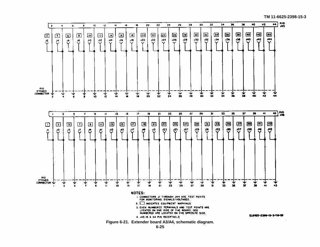
TM 11-6625-2398-15-3
Figure 6-21. Extender board A3/A4, schematic diagram.6-25

TM 11-6625-2398-15-3
Figure 6-22. Extender board A5, schematic diagram.
6-26

TM 11-6625-2398-15-3
Figure 6-23. Cable W21, schematic diagram.
6-27

TM 11-6625-2398-15-3
CHAPTER 7
REPAIRS
7-1. General Parts Replacement TechniquesAll components of the test facilities set that arerepairable can be easily replaced without specialprocedures. Parts located in the hybrid attenuatorassembly (fig. 7-1) are accessible when the chassis ofthe hybrid attenuator assembly is removed from itscase. Parts of the R-T front panel test adapter areaccessible when the bottom cover is removed.
7-2. Nonrepairable ComponentsThe following components of the test facilities set arenonrepairable.
a. Cables. Cables W13, W39 (except plugs P3through P6), W40, W41, W42, W43 and W48 (exceptplugs P2 through P6).
b. Adapters. Terminations, and Attenuators.(1) Adapters: CP1 through CP11(2) Terminations: AT3 through AT6(3) Attenuators: AT1/AT2, and W48 AT1
c. Couplers. W39CP1 and W39CP2.
7-3. Tools and Kits Required
Common name Tools or kit Technical manual
Tool Kit Tool kit, Electronic TM 11-5180Equipment TK-100/G
Printed wiring re- Repair kit, Printed TM 11-599pair kit Wiring Board MK-
772/U
7-4. Repairable ComponentsThe following components are repairable:
a. Hybrid Attenuator Assembly A1.b. Front Panel Test Adapter A2.
c. Extender Boards A3, A4, and A5.d. Cables W14/W15, W16, W21, W32, W39
(plugs P3 through P6), W45, W47, and W48 (plugs P2through P6).
e. Printed Circuit Board Extractors MP1 and MP2.
7-5. Repair of Printed Circuit Board ExtractorsIf printed circuit board extractors MP1 or MP2 becomebent or misaligned, bend back into proper shape with apair of pliers. After bending, check that the width of theextractor is correct for proper insertion into the pullerholes of the printed-circuit board.
7-6. Extender Board RepairIf the printed-circuit wiring on the board extendersbreaks, solder a short length of copper wire across thebreak. Use just enough heat to assure a well solderedbond, being careful not to burn the board base material.
7-7. Repair of Cable Assembliesa. General.
(1) A damaged cable connector should not berepaired, it should be replaced.
(2) Cable assemblies under one foot inlength:
(a) If a connector is damaged, replacethe cable assembly with a spare. If no spare isavailable, rebuild the cable assembly using a new lengthof cable and new and/or salvaged connectors. If a newlength of cable is not available, replace the damagedconnector.
(b) If the cable conductors aredamaged, replace the cable assembly with a spare. Ifno spare is available, rebuild the cable assembly
7-1

TM 11-6625-2398-15-3
Figure 7-1. Part locations, hybrid attenuator A1.
using a new length of cable and new or salvagedconnectors. If a new length of cable is not available,salvage as much of the damaged cable assembly aspossible, and replace one connector.
(3) Cable assemblies one foot in length orlonger.
(a) If a connector is damaged, replacethe connector.
(b) If less than one-tenth of the cable isdestroyed, repair the damaged cable assembly,replacing damaged connector(s).
(c) If more than one-tenth of the cableis destroyed, replace the cable assembly with a spare.If no spare is available, rebuild the assembly, using a
new length of cable and new or salvaged connectors. Ifa new length of cable is not available, salvage as muchof the damaged cable assembly as possible, andreplace one connector.
(4) To salvage a connector, reverse theprocedure that is used to attach it.
(5) To remove a damaged connector, cut thecable as closely as possible to the connector.
b. Cables W14/W15. If the cable is damagedbeyond repair, use a new six foot length of RG58C/U torebuild the cable assembly. If the repaired cable will bemore than five feet long, it may be repaired. Salvageconnectors whenever possible.
7-2

TM 11-6625-2398-15-3
NOTEA W14/W15 cable assembly that hasbeen shortened must not beconnected to the hybrid attenuatorRF SUM jack J2 during any of thetests. Write this on a tag, and attachthe tag to the shortened W14/W15cable.
Replace a connector as follows:(1) Remove any damaged connector by
cutting the cable as closely as possible to the damagedconnector.
(2) Slip the clamp nut, washer, and gasketover the cable (A fig. 7-5). Trim the jacket (dimension(D), A fig. 7-2).
(3) Comb out the braid smoothly and taperover the dielectric. Slide the braid clamp over the braidand push it against the cable jacket (B fig. 7-5).
(4) Bend the braid back over 'the braid clampand trim the excess braid. Make sure that the braiddoes not extend beyond the braid clamp shoulder (C fig.7-5).
(5) Cut the cable dielectric (dimension (A), Afig. 7-2), being careful not to nick the inner conductor.Tin the inner conductor (D fig. 7-5). Avoid melting orswelling the dielectric.
(6) Solder the contact to the inner conductor,making sure that the outer surfaces of the contact arefree of solder. Avoid using excessive heat. The contactshould be flush against the cable dielectric (E fig. 7-5).
(7) Insert the cable and parts into theconnector body. Care should be taken to insure that theknife edge of the braid clamp is properly seated in theV-groove gasket (F fig. 7-5). Tighten the clamp nutsecurely.
(8) Calibrate the repaired cable (para 6-12).c. Cable W16. If connector P1 or the conductors
of the cable are damaged the entire assembly must berebuilt. Use a new 6 inch length of RG-174/U. Salvageconnector P1 and the alligator clips, if they are
undamaged. A damaged alligator clip can be replacedwithout rebuilding the entire cable assembly.
(1) To attach connector P1 to the cableproceed as follows:
(a) Slide clamp nut and braid clampover cable (A, fig. 7-3). Trim the jacket (dimension (D),A, fig. 7-2).
(b) Cut the braid without damaging thedielectric (dimension (C), A, fig. 7-2). Cut the dielectric,being careful not to nick the inner conductor (dimension(A), A, fig. 7-2). Tin the inner conductor (B, fig. 7-3).
(c) Flare braid without combing. Insertwedge between braid and dielectric. Push the braidclamp over wedge to hold it in place (C fig. 7-3).
(d) Solder contact to center conductor(E, fig. 7-3), making sure outside surfaces are free ofsolder. Avoid use of excessive heat.
(e) Insert cable and parts intoconnector body. Rotate cable slightly to make surebraid clamp is seated properly (F, fig. 7-3). Tightenclamp nut securely to complete assembly.
(2) To fabricate the alligator clip assemblyproceed as follows:
(a) On the other end of the cable, strip2 3/8 inches of outer jacket (dimension (D), A, fig. 7-2).
(b) From the end of the cable, remove2 inches of braided outer conductor.
(c) From the end of the cable, remove3/8 inch of dielectric (dimension (A), A, fig. 7-2).
(d) From a 3-inch length of wire,remove .25 inch of insulation from one end and 3/8 inchfrom the other end (A, fig. 7-4).
(e) Place the 0.25 inch side against thebraid (B fig. 7-4).
(f) Slip the ferrule over the braid andthe 0.25 inch side of the wire, so that the ferrule bottomsagainst the cable jacket and the wire insulation (C, fig.7-4).
(g) Using a crimping tool, crimp theferrule to the conductors.
7-3

TM 11-6625-2398-15-3
(h) Solder alligator clips to the end ofthe 3-inch wire, and the end of the cable (D, fig. 7-4).
(i) Push an insulator over eachalligator clip (D, fig. 7-4).
d. Cable W21. If any part of the cable assembly isdamaged, the entire assembly must be rebuilt. Use anew six inch length of RG188A/U, and new or salvagedconnectors.
(1) To attach connector P2, proceed asfollows:
(a) Slide boot and outer ferrule overcable (A, fig. 7-7).
(b) Trim the cable jacket (dimension(D), A fig. 7-2).
(c) Cut the braid without damaging thedielectric (dimension (C), A, fig. 7-2). Cut the dielectric,being careful not to nick the inner conductor (dimension(A), A, fig. 7-2). Tin the center conductor. Avoidexcessive heat while tinning to prevent swelling of cabledielectric.
(d) Install ferrule clamp nut assemblyover cable so that the ferrule portion slides under braidand the insulator butts flush against cable dielectric.Slide outer ferrule over braid and up against nut. Crimpouter ferrule using crimping tool. Keep the cabledielectric bottomed against insulator (B fig. 7-7).
(e) Solder cable center conductor tocontact.
(f) Screw connector body onto ferruleclamp nut assembly and tighten (C, fig. 7-7).
(g) Push boot forward to completeassembly (D, fig. 7-7).
(2) To attach connector P1, proceed asfollows:
(a) Slide clamp nut over jacket of cable(A, fig. 7-8) and cut off jacket and braid from the end ofthe cable (dimension (A), B, fig. 7-2).
(b) Cut the dielectric, being careful notto nick the center conductor (dimension (B), B, fig. 7-2).
(c) Tin the center conductor (B fig. 7-8).(d) Slit the jacket at two places, 180
degrees apart and 1/8 inch long (B, fig. 7-8).(e) Insert the contact and insulator-
ferrule assembly between the braid and cable insulation(C, fig. 7-8) making sure the center conductor enters thehole in the contact.
(f) Solder contact to center conductor.(g) Insert the cable assembly into the
body assembly, and lock the cable assembly byscrewing the clamp nut to the body assembly (D, fig. 7-8).
e. Cable W32. A damaged cable assembly can berepaired if there is sufficient length of undamaged cableremaining to reach the power connections. Otherwiserebuild the assembly using a twenty foot length of CO-02MGF2/160335 cable. Salvage connector P1 if it isundamaged. Connector P2 cannot be salvaged.
(1) A damaged connector P1 will be replacedas follows:
(a) Remove the damaged connector.(b) Trim the jacket (dimension (A), C,
fig. 7-2).(c) Remove insulation (dimension (B),
C, fig. 7-2).(d) Remove plug body from the new
connector.(e) Loosen binding screws.(f) Push cable through cord grips and
wrap wires around binding screws. See figure 6-10 forproper connections.
(g) Tighten the binding screws.(h) Re-connect the plug body and
tighten the screws on the cord grip.(2) A damaged connector P2 will be replaced
as follows:(a) Remove the damaged connector.
7-4

TM 11-6625-2398-15-3
(b) Trim the jacket (dimension (A), C,fig. 7-2).
(c) Remove insulation (dimension (B),C, fig. 7-2).
(d) Unscrew the connector strain relieffrom a new connector, and slide it over the cable end.
(e) Remove the grommet from theconnector body and slide it over the wires.
(f) Crimp the cable wires to theconnector contacts. See figure 6-10 for properconnections.
(g) Push the grommet forward into theconnector body.
(h) Push the strain relief forward andtighten it.
f. Cable W39. Plugs P1 and P2 on this cable arenonrepairable. If either of these plugs are damaged, anew cable assembly must be obtained. If connectors P3through P6 are damaged, replace the connector ifsufficient RG-142A/U cable remains on the assembly topermit connection of P3/P4 and P5/P6 by couplers CP1and CP2. Replace connectors P3 through P6 byrepeating steps b(1) through b(8).
g. Cable W45. If any part of the cable assembly isdamaged, the entire assembly must be rebuilt. Use anew six inch length of RG-58C/U, and new or salvagedconnectors.
(1) Attach connector P2 to the new cable byrepeating steps b(2) through b(7).
(2) To attach connector P1 to the new cableproceed as follows:
(a) Slide clamp nut and braid clampover cable (A fig. 7-9). Trim the jacket (dimension (I)),A, fig. 7-2).
(b) Cut the braid without damaging thedielectric (dimension (C), A, fig. 7-2). Cut the dielectric,being careful not to nick the inner conductor (dimension(A), A, fig. 7-2). Tin the inner conductor (B, fig. 7-3).
(c) Flare braid without combing. Insertwedge between braid and dielectric. Push the braidclamp over wedge to hold it in place (C, fig. 7-3).
(d) Slip reducer bushing over dielectricand insulator bushing over conductor (D, fig. 7-3).
(e) Solder contact to center conductor(E, fig. 7-3), making sure outside surfaces are free ofsolder. Avoid use of excessive heat.
(f) Insert cable and parts intoconnector body. Rotate cable slightly to make surebraid clamp is seated properly (F, fig. 7-3). Tightenclamp nut securely to complete assembly.
h. Cable W47. If any part of the cable assembly isdamaged, the entire assembly must be rebuilt. Use anew six inch length of RG-58C/U, and new or salvagedconnectors.
(1) Attach connector P2 to the new cable byrepeating steps b(2) through b(7).
(2) To attach connector P1 to the new cableproceed as follows:
(a) Slide clamp nut and braid clampover cable (A fig. 7-3). Trim the jacket (dimension (D),A, fig. 7-2).
(b) Cut the braid without damaging thedielectric (dimension (C), A, fig. 7-2). Cut the dielectric,being careful not to nick the inner conductor (dimension(A), A, fig. 7-2). Tin the inner conductor (B, fig. 7-3).
(c) Flare braid without combing. Insertwedge between braid and dielectric. Push braid clampover wedge to hold it in place (C, fig. 7-3).
(d) Slip reducer bushing over dielectricand insulator bushing over conductor (D, fig. 7-3).
(e) Solder contact to center conductor(E, fig. 7-3), making sure outside surfaces are free ofsolder. Avoid use of excessive heat.
(f) Insert cable and parts intoconnector body. Rotate cable slightly to make surebraid clamp is seated properly (F, fig. 7-3). Tightenclamp nut securely to complete assembly.
7-5

TM 11-6625-2398-15-3
i. Cable W48. This cable is not repairable ifconnector P1, or one or more of the five coaxial cablesis damaged, so as not to permit connection in the testset-up. If connectors P2 through P6 are damaged, thecable can be repaired. A damaged connector can bereplaced as follows:
(1) Slip nut assembly over cable (A, fig. 7-6).(2) Cut off 1/4 inch of jacket and braid from
the end of the cable (dimension (A), B, fig. 7-2).(3) Cut off dielectric (dimension (B), fig. 7-2)
from jacket and braid. Do not nick the inner conductor.(4) Tin the inner conductor (B, fig. 7-6).(5) Cut 3 slits 1/8 inch long and 120 degrees
apart in outer jacket only (C, fig. 7-6) without disturbingbraid. Raise outer jacket and braid away from dielectricin order to facilitate the entry of contact-wedgeassembly. Straighten inner conductor if necessary.
(6) Slide contact-wedge assembly underbraid and jacket (D, fig. 7-6). Push back as far aspossible, making sure that inner conductor is visiblethrough side hole of contact. Solder contact to innerconductor through side hole and make sure outsidesurfaces are free of solder. Avoid use of excessiveheat.
(7) Insert cable and contact-wedge assemblyinto body assembly. Tighten nut securely to completeassembly.
j. Cable A1W1 (fig. 7-1). If the cable is damagedbeyond repair, use a new eight foot length of RG-222/Uand new or salvaged connectors, to rebuild the cableassembly. If the damaged cable can still be used, repairthe longer end of the cable.
NOTEIt is necessary that the insertionlosses of the difference channel be atleast 0.2dB less than the insertionlosses of the sum channel, at a 0dBsetting of the variable attenuator.After repairing a damaged cable orreplacing a connector, check to see
that the 0.2dB difference still exists.If it does not, fabricate a new cable.
(1) A damaged connector will be replaced asfollows:
(a) Repeat steps b(1) through b(4).(b) Cut the cable dielectric (dimension
(A), A, fig. 7-2), being careful not to nick the innerconductor.
(c) Clean the center conductor of thecable with muriatic acid.
(d) Tin the center conductor. Use typeSN60WS solder.
(e) Wash the center conductor inammonia.
(f) Rinse the center conductor inisopropyl alcohol.
(g) Solder the contact to the innerconductor, making sure that the outer surfaces of thecontact are free of solder. Use type SN60WS solder.Avoid using excessive heat. The contact should beflush against the cable dielectric (E, fig. 7-5).
(h) Insert. the cable and parts into theconnector body. Care should be taken to insure that theknife edge of the braid clamp is properly seated in theV-groove gasket (F, fig. 7-5). Tighten the clamp nutsecurely.
(2) After the cable assembly is completed,calibrate the hybrid attenuator (para 6-10) and measurethe hybrid attenuator VSWR (para 6-11).
k. Cable A1W2 (fig. 7-1). If the cable assembly isdamaged beyond repair, use a new six foot length ofRG-222/U and new or salvaged connectors to rebuildthe cable assembly. If the damaged cable can still beused, repair the longer end of the cable.
(1) Replace a damaged connector as follows:(a) Repeat steps b(1) through b(4).(b) Repeat steps i(1)(b) through i(1)(h).
(2) After the cable assembly is completed,calibrate the hybrid attenuator (para 6-10) and
7-6

TM 11-6625-2398-15-3
measure the hybrid attenuator VSWR (para 6-11).l. Cable A1W3. If any part of the cable assembly
is damaged, the entire assembly must be rebuilt. Use anew six inch length of RG-58C/U, and new or salvagedconnectors.
(1) Attach connectors P1 and P2 to the newcable by repeating steps b(2) through b(7).
(2) Calibrate the hybrid attenuator (para 6-10)and measure the hybrid attenuator VSWR (para 6-11).
m. Cable to A1J1 (fig. 7-1). If any part of the cableassembly is damaged, the entire assembly must berebuilt. Use a new eight inch length of RG-58C/U, andnew or salvaged connectors.
(1) To attach connector A1J1, repeat stepsb(2) through b(7).
(2) To attach connector A1P1, proceed asfollows:
(a) Slip nut assembly over cable (A, fig.7-6).
(b) Cut off 1/2 inch of jacket and braidfrom the end of the cable (dimension (A), B, fig. 7-2).Do not damage the cable dielectric.
(c) Cut off dielectric (dimension (B), B,fig. 7-2) from jacket and braid. Do not nick the innerconductor.
(d) Tin the inner conductor (B, fig. 7-6).(e) Cut 3 slits 1/8 inch long and 120
degrees apart in outer jacket only (C, fig. 7-6) withoutdisturbing braid. Raise outer jacket and braid away fromdielectric in order to facilitate the entry of contact-wedgeassembly. Straighten inner conductor if necessary.
(f) Slide contact-wedge assemblyunder braid and jacket (D, fig. 7-6). Push back as far aspossible, making sure that inner conductor is visiblethrough side hole of contact. Solder contact to innerconductor through side hole and make sure outsidesurfaces are free of solder. Avoid used of excessiveheat.
(g) Insert cable and contact-wedgeassembly into body assembly. Tighten nut securely tocomplete assembly.
(3) Calibrate hybrid attenuator (para 6-10)and measure the hybrid attenuator VSWR (para 6-11).
n. Cable to A1J4 (fig. 7-1). If any part of the cableassembly is damaged, the entire assembly must berebuilt. Use a new eight inch length of RG-58C/U andnew or salvaged connectors.
(1) To attach connectors A1J4, repeat stepsb(2) through b(7).
(2) The procedure for attaching A1P2 is asfollows:
(a) Repeat steps b(2) through b(5).(b) Insert cable into angle body. Make
sure that inner conductor is nested into slot of contact,and knife edge of braid clamp is properly seated in V-groove gasket. Tighten clamp nut securely.
(c) Solder inner conductor to contactthrough opening in body.
(d) Place cover in position and screwinto place to complete assembly.
(3) Calibrate the hybrid attenuator (para 6-10)and measure the hybrid attenuator VSWR (para 6-11).
o. Cable to A1J5 (fig. 7-1). If any part of the cableassembly is damaged, the entire assembly must berebuilt. Use a new eight inch length of RG-58C/U andnew or salvaged connectors.
(1) To attach connector A1J5, repeat stepsb(2) through b(7).
(2) To attach connector A1P3 to the cable,repeat steps 1(2)(a) through 1(2)(g).
(3) Calibrate the hybrid attenuator (para 6-10)and measure the hybrid attenuator VSWR (para 6-11).
p. Cable to A2P1. If the conductors of the cableare damaged beyond repair, rebuild the cable assemblywith SM-657812-24-9 wire. See figure 6-20 for properconnections. Salvage
7-7

TM 11-6625-2398-15-3
connector A2P1 whenever possible. The procedure forreplacing a damaged connector A2P1 is as follows:
(1) Remove the damaged connector bycutting the cable as closely as possible to the damagedconnector.
(2) Remove approximately 1 inch of tubing.(3) Remove 0.38 inch of insulation from each
wire.(4) Tin each conductor end.
(5) Unscrew strain relief from a newconnector and slide it back over the cable.
(6) Insert boot into tubing.(7) Push grommet over wires.(8) Solder each wire to the proper connector
contact. See figure 6-20 for proper connections.(9) Push grommet forward into body of
connector.(10) Push the strain relief forward and tighten.
7-8

TM 11-6625-2398-15-3
Figure 7-2. Cable stripping details.
7-9

TM 11-6625-2398-15-3
Figure 7-3. Assembly of connectors on cables W16, W45 and W47, andportions of hybrid attenuator cables.
7-10

TM 11-6625-2398-15-3
Figure 7-4. Assembly of alligator clips on cable W16.
7-11
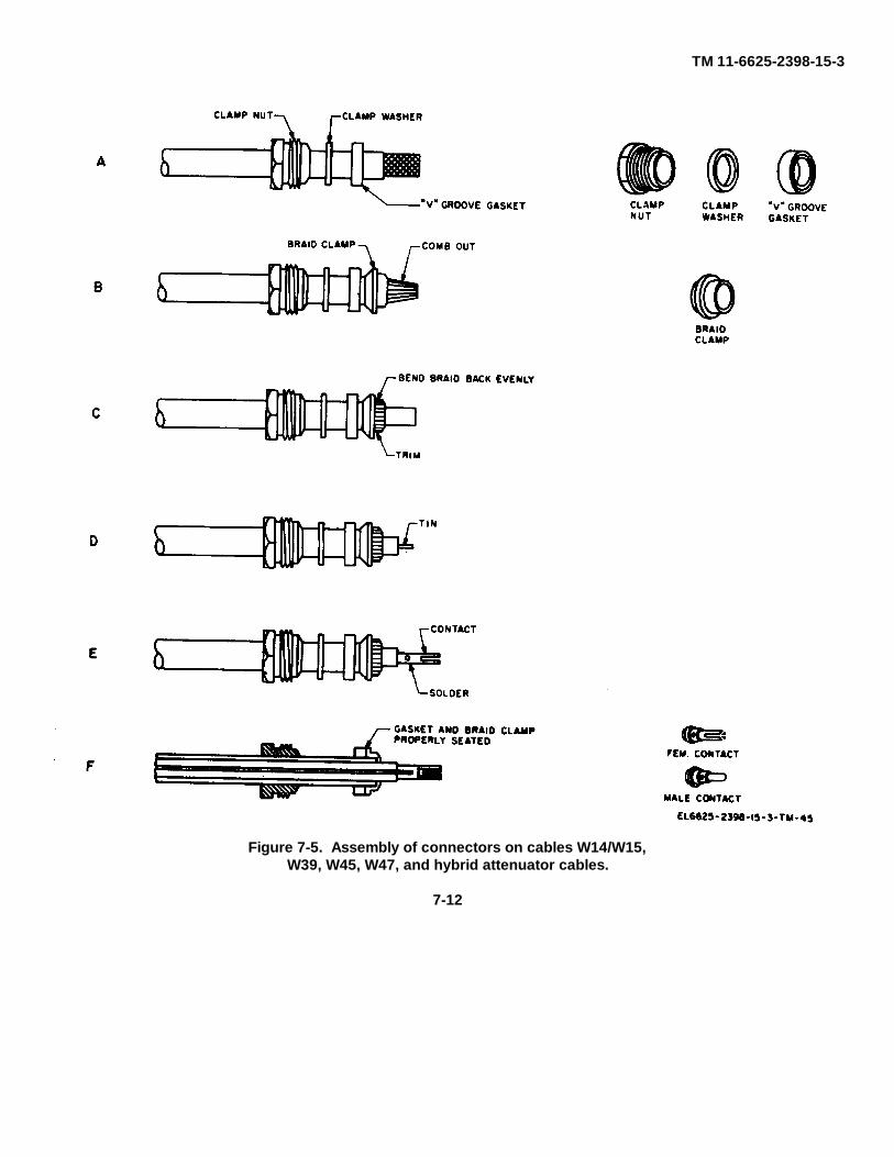
TM 11-6625-2398-15-3
Figure 7-5. Assembly of connectors on cables W14/W15,W39, W45, W47, and hybrid attenuator cables.
7-12

TM 11-6625-2398-15-3
Figure 7-6. Assembly of connectors on cable W48 andportions of hybrid attenuator cables.
7-13

TM 11-6625-2398-15-3
Figure 7-7. Assembly of connector W21P2.
7-14

TM 11-6625-2398-15-3
Figure 7-8. Assembly of connector W21P1.
7-15

TM 11-6625-2398-15-3
CHAPTER 8
GENERAL SUPPORT TESTING PROCEDURES
8-1. Generala. Testing procedures are prepared for use by
Signal Field Maintenance Shops and Signal ServiceOrganizations responsible for general supportmaintenance of signal equipment to determine theacceptability of repaired equipment. These proceduresset forth ,specific requirements that repaired equipmentmust meet before it is returned to the usingorganization. These procedures may also be used as aguide for testing equipment that has been repaired if theproper tools and test equipments are available. Asummary of the performance standards is given inparagraph 8-11.
b. Comply with the instructions -preceding eachchart before proceeding to the chart. Perform each stepin sequence. Do not vary the sequence. For each step,perform all the actions required in the Test equipment
control settings and Equipment under test controlsettings columns; then perform each specific testprocedure and verify it against its performancestandard.
8-2. Test Equipment and MaterialAll test equipment required to perform the testingprocedures given in this chapter are listed in thefollowing charts and is authorized under TA-11-17,Signal Field Maintenance Shops, and TA-11-100(11-17),Allowances of Signal Corps Expendable Supplies forSignal Maintenance Shop, Continental United States.
a. Test Equipment.
Nomenclature Federal Technical manualstock no.
Signal Generator SG-340/G 6625-553-7326 NAVSHIPS 9365Multimeter AN/PSM-6B 6625-957-4374 TM 11-6625-475-10Ohmmeter ZM-21A/U 6625-246-5880 TM 11-2050Standing Wave Ratio Indicator AN/
UPM-108A 6625-682-4494 TM 11-6625-335-12Coaxial Slotted line IM-92/U 6625-356-0314 TM 11-5109Low Paz Filter Hewlett-Packard
Co. Model 350C 5915-503-0533 _____Crystal Detector Hewlett-Packard
Co. Model 423A 4940-871-8505 _____Variable Attenuator, Alfred Elec-
tronics Model E101 _____ _____Adapter (type N male to type BNC
female) UG-201A/U 5935-201-3090 _____Adapter (type N female to typ
BNC female) UG-606/U _____ _____50 ohm Termination, Microlab/
FXR TA-6MN _____ _____Adapter (type BNC female to BNC
female) UG-914/U _____ _____
b. Materials. The materials below required for thegeneral support testing procedures are supplied with thetest facilities set.
Materials Reference designation Federal stock no.
Fixed Attenuators AT1/AT2 _____
Materials Reference designation Federal stock no.
Terminations AT3/AT4 _____Cables W14/W15 _____Cable A1W3 _____Adapters CP7/CP8 5935-201-3090
8-1

TM 11-6625-2398-15-3
8-3. Modification Work OrdersThe performance standards listed in the tests (para 8-4through 8-10) are based on having no modification workorders performed on the test facilities set.
8-4. Continuity Tests on Cables, Extender Boards and Front Panel Test Adapter
a. Test Equipment and Materials. MultimeterAN/PSM-6B.
b. Test Connections and Conditions. Connect theequipment shown in figure 8-1 in accordance with thedirections in the steps of the procedure below.
c. Procedure.
Step Test equipment Equipment under Test PerformanceNo. control settings test control settings procedure standard
1 AN/PSM-6B None Plug test leads into multimeter and NoneFunction: OHMS short circuit free ends of test leads.Range: R X 1 Adjust OHMS ZERO until meter
pointer reads zero on the OHMSscale.
2 Remove short circuit on test leads of AN/ a. Connect one multimeter test lead to a. Meter must indicatePSM-6B and leave controls in positions given the center conductor of one plug on zero ohms (continuity)in step 1. Cable W14/W15. Connect the other
test lead to the center conductor of theplug on the other end of the cable.b. Connect one multimeter test lead to b. Meter must indicatethe outer shell of one plug on cable zero ohms (continuity) W14/W51. Connect the other test leadto the outer for each test shell of theplug on the other end of the cable.c. Perform steps a and b for the other c. Meter must indicateW14/W15 cable and cable W16, W21, zero ohms (continuity) forW16, W21, W45 and W47. each test on each cable.
Note.One end of cable W16 has alligatorclips, P2 is the center conductor termina-tion and P3 is the shell shield termination.
Note.1. Consult the schematic diagrams for cables W32, W39 through W43 and W48 (fig. 6-10, 6-11 through 6-15 and 6-18,
respectively) to perform step 3. The schematic diagrams identify the lead terminations and shields (if any) in each cable.Perform test procedures a, b, and c below (as required) for continuity checks of cables W2, W39 through W43 and48.
2. Cable W32 is unshielded and does not have shielded leads. Therefore, test procedures a and b below are not to beperformed for this cable.
3. Cable W39 is supplied with couplers W39CP1 and W39CP2. Both couplers must be connected on cable W39 whenperforming test procedures b and c below.
4. Cables W39 and W48 are unshielded. Therefore, test procedure a below is not to be performed on these cables.5. Cable W48 is supplied with five separate coaxial p lugs and one attenuator on one end of the cable. Perform test
procedure b for each separate coaxial plug. Cable pin E will provide an approximate meter reading of 91 ohms whenperforming test procedure c below, instead of zero ohms.
3 Leave controls and test leads in position in- a. Check shielding, bonded to the a. Meter must indicatedicated in step 2. shell of the plugs, by connecting zero ohms (continuity).
one multimeter teat lead to the hell See notes 2 and 4 aboveof one plug and the other test lead for cables W32, W39 andto the shell of the other plug. W48.b. Check individual wire shielding b. Meter must indicateby progressively connecting the zero ohms (continuity) formultimeter test lead to each wire each shield. See notes 2,shield pin connection on the plugs 3, and 5 above for cablesat each end of the cable. W32, W39 and W48.c. Check continuity of cable wires c. Multimeter mustby progressively connecting the indicate zero ohmsmultimeter test leads to the wire (continuity) for each wire.connecting pins on the plugs at each See notes 3 and 5 aboveend of cable. for cables W3 and W48.
8-2

TM 11-6625-2398-15-3
Figure 8-1. Cables, front panel test adapter and extender boards, continuity test conditions.
8-3

TM 11-6625-2398-15-3
Step Test equipment Equipment under Test PerformanceNo. control settings test control settings procedure standard
Note.Consult the schematic diagrams for printed circuit extender boards A3/A4 (fig. 6-21) and A5 (fig. 6-22) to perform step4. Perform the procedures a, b, c, and d below for boards A3/A4 and test procedures a and b below for board A5.
4 Leave controls and test leads in positions in- a. Check for short circuit by connect- a. Meter must indicatecated in step 2. ing multimeter test leads to first two open circuit.
adjacent pins or etched terminalsat one end of the aboard. Move thetwo multimeter test leads successively,by advancing each test had one pin ata time, across the board. Repeat abovefor the etched terminals on the oppositeside of the A3/A4 boards.b. Check board continuity by connecting b. Meter must readone multimeter test lead to the pin or zero ohms (continuity)etched terminal at one end of the board for each pin orand the corresponding pin (A5) or etched terminal.connector contact (A3/A4) at theopposite end of the board.c. Check for short circuits by connect- c. Meter must indicateing multimeter test leads to etched open circuit.terminals directly adjacent onopposite sides of the A3/A4 boards.d. Check continuity to test points d. Meter must indicateon A3/A4 boards by connecting one zero ohms (continuity)multimeter test lead to the first con- for each test point.tact of J45 and the test point (J1 or J2)immediately below. Advance testleads successively across the boardto last contact of J45 and the last testpoint (J43 or J44). Repeat abovefor the opposite side of the board.
5 Leave controls and Adapter Test MX- a. Connect one multimeter test lead a. Meter must indicatetest leads in posi- 8565, TPM-24(V). to VIDEO jack J1 on front panel. zero ohms (continuity)tions indicated in VIDEO switch to Successively connect the other test for each switch position.step 2. positions indicated lead to plug Pi contacts listed below.
In test procedure. Rotate the VIDEO switch to the positioncorresponding to the plug contact belowfor each test.Test lead to: VIDEO switch
positionP1-R RETURN (GND)P1-M ISLS GATEP1-N CHAL VIDEOP1-C SUM IF VIDEOP1-D DIFF IF VIDEOP1-P MOD PULSEP1-F RCVR VIDEOP1-J CHAL MON DET
INCIDENT PWRP1-K CHAL MON DET
REFL PWRb. VIDEO switch in b. Connect multimeter test leads to b. Meter must readany position. GND jack J8 on front panel and zero ohms (continuity).
other lead to contact R of plug P1.c. Same as b above. c. Successively connect the multi- c. Meter must read
meter test leads to the jacks and zero ohms (continuity)plug P1 contacts as follows: for each test.Test lead to: VIDEO switch
positionRT FAULT J2 P1-GLVPS MON J3 P1-E
8-4

TM 11-6625-2398-15-3
Step Test equipment Equipment under Test PerformanceNo. control settings test control settings procedure standard
Test lead to: VIDEO switchposition
CHAL MONENABLE J4 P1-H
SUM XTALCUR J5 P1-B
ISLS INHIBIT J6 P1-LDIFF XTAL CURRT FAULT J2 P1-GLVPS MON J3 P1-ECHAL MON
ENABLE J4SUM XTAL
CUR J5 P1-BJ7 P1-A
d. Video switch to d. Successively connect one multi- d. Meter must indicatepositions indicated in meter test lead to the active pins on an open circuit for eachtest procedure. plug P1 (figure 6-20). Successively test, except for the
connect the other multimeter lead switch positions andto J1 (rotating VIDEO switch S1 jacks requiring continuitythrough all nine positions) and J2 to plug P1 in a, b and cthrough J8 for each active pin. above.
8-5. Insulation Resistance Tests on Cablesa. Test Equipment and Materials. Ohmmeter ZM-
21A/U.b. Test Connections Conditions. Connect the
equipment as shown in figure 8-2 in accordance with thedirections in the steps of the procedure below. Toaccomplish connection of the test leads from the LINEand GROUND terminals of Ohmmeter ZM-21A/U to thepin contacts of the cable connectors, proceed as followswhenever applicable:
(1) When possible, connect the two test leadsto opposite ends of the cables to avoid shorting.
(2) To connect a test lead to a male pin of acable connector, adapt the alligator clip by connecting itto a female pin of the correct size.
(3) To connect a test lead to a female pin of acable connector, adapt the alligator clip by connecting itto a male pin of the correct size, or to a solid wire of thecorrect size.
Step Test equipment Equipment under Test PerformanceNo. control settings test control settings procedure standard
1 ZM-21A/U NoneWarning:
Test leads of Ohmmeter ZM-21A/U are at potentials up to 500 volts when the ohmmeter hand crank is being rotated.To avoid injury make all connections when the hand crank is not being rotated. DO NOT handle the test leads whilethe crank is rotating.
Check insulation resistance of coaxialcables W13, W14/W15(2), W16.W21, W45 and W47 as follows:a. Connect the LINE terminal of theohmmeter to the center contact of oneplug.b. Connect the GROUND terminal ofthe ohmmeter to the shell of a plug.c. Wrap an uninsulated wire aroundthe outer covering of the cable andconnect the wire to the GUARDterminal of the ohmmeter.d. Rotate the hand crank of the Meter reading of 100ohmmeter at 160 (minimum) revolu- megohms or highertions per minute (rpm) and read the must be obtained.insulation resistance on the meter.
2 Observe Warning in step 1 above. Check insulation resistance of powercable W32 (fig. 6-10) as follows:a. Connect the LINE and GROUND
8-5

TM 11-6625-2398-15-3
Figure 8-2. Cable insulation resistance, test conditions.
8-6

TM 11-6625-2398-15-3
Step Test equipment Equipment under Test PerformanceNo. control settings test control settings procedure standard
terminals of the ohmmeter to con-tacts of the plugs, which are con-nected to the two wires of the cable.b. Repeat c and d of step 1. Meter reading of 100
megohms or highermust be obtained.
3 Observe Warning in step 1 above. Check insulation resistance on cableW39 (fig. 6,11) as follows:
Note.Couplers W39CP1 and W39CP2 mustbe connected in cable W39.
a. Connect the GROUND terminal ofthe ohmmeter to the outer shell of oneof the coaxial connectors on a plug.b. Repeat c of step 1.c. Successively (stopping handcranking while connecting test leadbetween each test) connect theLINE terminal to each plug contact(total 8) connected to wires.d. Repeat d of step 1 for the eight Meter reading of 100tests. megohms or higher
must be obtained oneach test.
4 Observe Warning in step 1 above. Check insulation resistance on cableW40 (fig. 6-12) as follows:a. Connect the GROUND terminal ofthe ohmmeter to plug contact pin 4.b. Repeat c of step 1.c. Repeat c of step 3 for plug con-tacts 6 and 9.d. Repeat d of step 1 for both tests. Meter reading of 100
megohms or highermust be obtained forboth tests.
e. Connect the GROUND terminalof the ohmmeter to the outer shellof either plug on the cable.f. Repeat c of step 3 for the balanceof the plug contacts (7) of the cable.g. Repeat d of step 1 for the seven Meter reading of 100tests. megohms or higher
must be obtained foreach test.
h. Connect the LINE terminal of theohmmeter successively (stoppinghand cranking while connecting testlead between each tests to each plugcontact pin carrying a wire.i. Concurrently with step h connect the Meter reading of 100GROUND terminal to each of the other megohms or higherplug contact pins connected to wires, must be obtained forrepeating d of step 1 for each wire. each test.Perform 36 separate tests until allwires have been tested with respectto each other.
5 Observe Warning in step 1 above. Check insulation resistance of cableW41 (fig. 6-13) as follows:a. Connect the GROUND terminal
8-7

TM 11-6625-2398-15-3
Step Test equipment Equipment under Test PerformanceNo. control settings test control settings procedure standard
of the ohmmeter to plug contact pin 22.b. Repeat c of step 1.c. Repeat c of step 3 for plug contactpins 20 and 23.d. Repeat d of step 1 for both tests. Meter reading of 100
megohms or highermust be obtained forboth tests.
e. Connect the GROUND terminalof the ohmmeter to the outer shellof either plug on the cable.f. Repeat c of step 3 for the balanceof the tests (4) of the cable.g. Repeat d of step 1 for the four tests. Meter reading of 100
megohms or highermust be obtained foreach test.
h. Repeat h and i of step 4 for the Meter reading of 100six plug contact pins (15 tests) con- megohms or highernected to wires. must be obtained for
each test.6 Observe Warning in step 1 above. Check insulation resistance of cable
W42 (fig. 6-14) as follows:a. Connect the GROUND terminal ofthe ohmmeter to plug contact pin A11.b. Repeat c of test procedure for step 1.c. Repeat c of step 3 for plug contactpins A12, A13, and A14.d. Repeat d of step 1 for the three tests. Meter reading of 100
megohms or highermust be obtained oneach test.
e. Connect the GROUND terminal ofthe ohmmeter to plug contact pin A19.f. Repeat c of step 3 for plug contactpins A15 through A18.g. Repeat d of step 1 for the four tests. Meter reading of 100. megohms or higher
must be obtained foreach test.
h. Connect the GROUND terminal ofthe ohmmeter to plug contact pin A23.i. Repeat c of step 3 for plug contactpins A21 and A22.j. Repeat d of step 1 for both tests. Meter reading of 100
megohms or highermust be obtained forboth tests.
k. Connect the GROUND terminalsuccessively between tests to the re-spective outer coaxial terminal ofcontact pins B1, B3, B5. B7, B9,B11, C1, C3, C5, C7, C9 and C11.l. Concurrently with step k connect theLINE terminal of the ohmmeter to thecenter contacts of the coaxial terminals.m. Repeat d of step 1 for the 12 tests. Meter reading of 100
megohms or higher
8-8

TM 11-6625-2398-15-3
Step Test equipment Equipment under Test PerformanceNo. control settings test control settings procedure standard
must be obtained oneach test.
n. Connect the GROUND terminalof the ohmmeter to the outer shellof either plug on the cable.o. Repeat c of step 3 for plug contactpins A1 through A10, A20, B2, B4, B6,B8, B10, C2, C4, C6, C8 and C10.p. Repeat d of step 1 for the 21 tests. Meter reading of 100
megohms or highermust be obtained foreach test.
q. Repeat h and i of step 4 for plug Meter reading of 100contact pins A1 through A10, A20, megohms or higherB2, B4, B6, B8, B10, C2, C4, C6, must be obtained forC8 and C10 (210 tests). each test.
7 Observe Warning in step 1 above. Check insulation resistance of cableW43 (fig. 6-15) as follows:a. Connect the GROUND terminal ofthe ohmmeter to plug contact pin 2.b. Repeat c of step 1.c. Repeat c of step 3 for plug contactpins 4 and 5.d. Repeat d of step I for both tests. Meter reading of 100
megohms or highermust be obtained onboth tests.
e. Connect the GROUND terminal ofthe ohmmeter to plug contact pin 12.f. Repeat c of step 8; for plug contactpins 6, 7 and 10.g. Repeat d of step 1 for the three tests. Meter reading of 100
megohms or highermust be obtained foreach test.
h. Connect the GROUND terminal ofthe ohmmeter to plug contact pin 16.i. Repeat c of step 3 for plug contactpins 14, 17, 19 and 21.j. Repeat d of step 1 for the four tests. Meter reading of 100
megohms or highermust be obtained foreach test.
k. Connect the GROUND terminal ofthe ohmmeter to plug contact pin 1.l. Repeat c of step 3 for plug contactpins 18 and 23.m. Repeat d of step 1 for both tests. Meter reading of 100
megohms or highermust be obtained onboth tests.
n. Connect the GROUND terminalof the ohmmeter to the outer shellof either plug on the cable.o. Repeat c of step 3 for plug contactpins 3, 8, 9, 11, 13 and 22.p. Repeat d of step 1 for the six tests.
8-9

TM 11-6625-2398-15-3
Step Test equipment Equipment under Test PerformanceNo. control settings test control settings procedure standard
q. Repeat h and i of step 4 for plug Meter reading of 100contact pins 3, 8, 9, 11, 13, 18, 22 megohms or higherand 23 (28 tests). must be obtained on
each test.8 Observe Warning in step 1 above. Check insulation resistance of cable
W48 (fig. 6-18) as follows:a. Connect the ohmmeter GROUNDterminal to the outer terminal ofplug P2.b. Connect the LINE terminal of theohmmeter to the center coaxial ter-minal of A on plug P1.c. Repeat c of step 1.d. Repeat d of step 1. Meter reading of 100
megohms or highermust be obtained.
e. Repeat a, b and d for Meter reading of 100P3 to P1-C megohms or higherAT1(P4) to P1-E must be obtained onP5 to P1-F each test.P6 to P1-B
8-6. Hybrid Attenuator Insertion Loss Measurement between RF IN/OUT and RF SUM Connectors
a. Test Equipment and Materials.(1) Signal Generator SG-340/G.(2) Variable Attenuator, Alfred Electronics Model
E101.(3) Standing Wave Radio Indicator AN/UPM-
108A.(4) Crystal Detector HP-423A.(5) Adapter UG-201A/U.(6) Adapters CP7/CP8 (2).
(7) Fixed Attenuator AT1/AT2(2).(8) Termination AT3/AT4(1).(9) 50-ohm Terminations (2), Microlab/FXR TA-
6MN.(10) Cables W14/W15 (2).(11) Adapter UG-606/U.
b. Test Connections and Conditions. Initially connectthe equipment as shown in solid lines, figure 8-3. Disconnectthe hybrid attenuator and connect the variable attenuator(connections shown in broken lines) as directed in theprocedure below.
Step Test equipment Equipment under Test PerformanceNo. control settings test control settings procedure standard1 a. SG-340/G None a. Set the MEGACYCLES dial to
POWER: ON 1090 with the frequency controlFunction switch: knob. Turn on the signal generator
CW and allow a minimum of 20 minutesMEGACYCLES: warm-up period before proceeding.
1090b. AN/UPM-108A b. Turn on the standing wave ratioPower: ON indicator and allow a minimum ofMETER SCALE: 10 minute warm-up period before
NORMAL proceeding.INPUT SELECTOR:
XTAL-200 K Ωc. SG-340/G c. Turn off the signal generator and
8-10

TM 11-6625-2398-15-3
Figure 8-3. Hybrid attenuator sum channel (between RF IN/OUT and RF SUM connectors) insertion loss, testconnections.
8-11
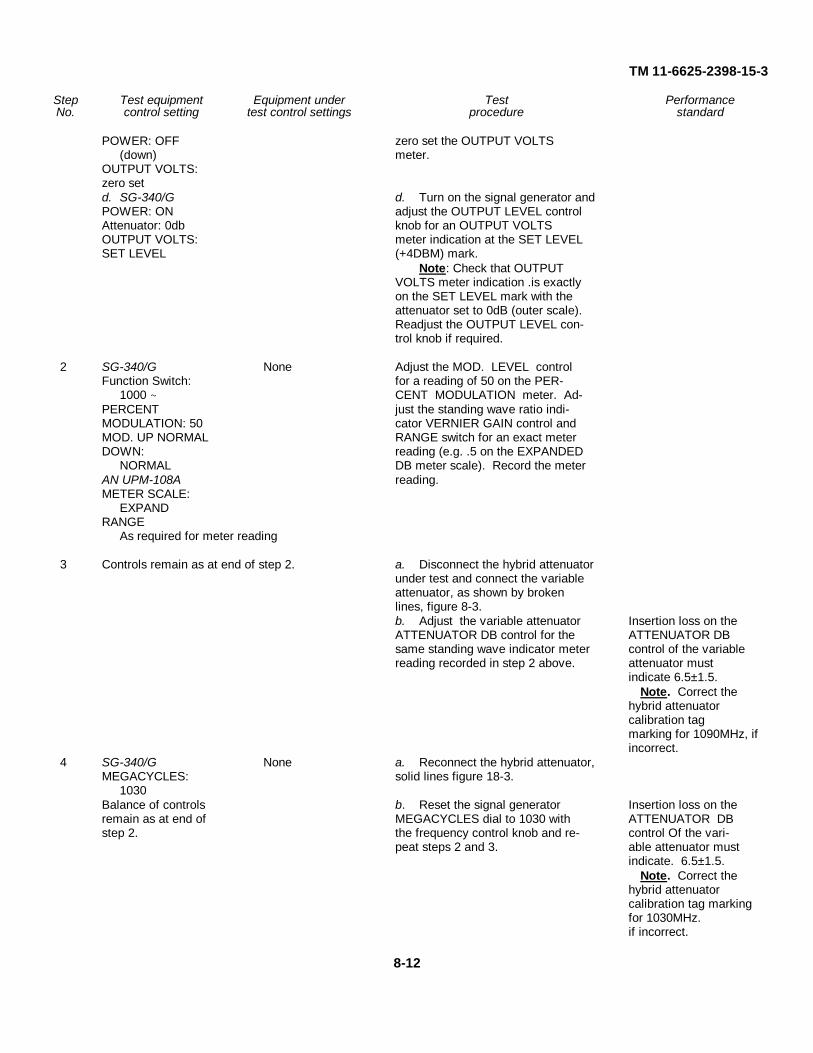
TM 11-6625-2398-15-3
Step Test equipment Equipment under Test PerformanceNo. control setting test control settings procedure standard
POWER: OFF zero set the OUTPUT VOLTS(down) meter.
OUTPUT VOLTS:zero setd. SG-340/G d. Turn on the signal generator andPOWER: ON adjust the OUTPUT LEVEL controlAttenuator: 0db knob for an OUTPUT VOLTSOUTPUT VOLTS: meter indication at the SET LEVELSET LEVEL (+4DBM) mark.
Note: Check that OUTPUTVOLTS meter indication .is exactlyon the SET LEVEL mark with theattenuator set to 0dB (outer scale).Readjust the OUTPUT LEVEL con-trol knob if required.
2 SG-340/G None Adjust the MOD. LEVEL controlFunction Switch: for a reading of 50 on the PER-
1000 CENT MODULATION meter. Ad-PERCENT just the standing wave ratio indi-MODULATION: 50 cator VERNIER GAIN control andMOD. UP NORMAL RANGE switch for an exact meterDOWN: reading (e.g. .5 on the EXPANDED
NORMAL DB meter scale). Record the meterAN UPM-108A reading.METER SCALE:
EXPANDRANGE
As required for meter reading
3 Controls remain as at end of step 2. a. Disconnect the hybrid attenuatorunder test and connect the variableattenuator, as shown by brokenlines, figure 8-3.b. Adjust the variable attenuator Insertion loss on theATTENUATOR DB control for the ATTENUATOR DBsame standing wave indicator meter control of the variablereading recorded in step 2 above. attenuator must
indicate 6.5±1.5.Note. Correct the
hybrid attenuatorcalibration tagmarking for 1090MHz, ifincorrect.
4 SG-340/G None a. Reconnect the hybrid attenuator,MEGACYCLES: solid lines figure 18-3.
1030Balance of controls b. Reset the signal generator Insertion loss on theremain as at end of MEGACYCLES dial to 1030 with ATTENUATOR DBstep 2. the frequency control knob and re- control Of the vari-
peat steps 2 and 3. able attenuator mustindicate. 6.5±1.5.
Note. Correct thehybrid attenuatorcalibration tag markingfor 1030MHz.if incorrect.
8-12

TM 11-6625-2398-15-3
Figure 8-4. Hybrid Attenuator difference channel (between RF IN/OUT and ATTEN IN/RF DIFF connectors)insertion loss, test connections.
8-13

TM 11-6625-2398-15-3
8-7. Hybrid Attenuator Insertion Loss Measurementbetween RF IN/OUT and ATTEN IN/RF DIFFConnectors
a. Test Equipment and Materials.(1) Signal Generator SG-340/G.(2) Variable Attenuator, Alfred Electronics
Model E101.(3) Standing Wave Ratio Indicator AN/UPM-
108A.(4) Crystal Detector HP-423A.(5) Adapter UG-201A/U.(6) Adapters CP7/CP8 (2).
(7) Fixed Attenuators AT1/AT2(2).(8) Termination AT3/AT4(1).(9) 50-ohm Terminations (2), Microlab/FXR
TA-6MN.(10) Cables W14/W15(2).(11) Cable A1W3.(12) Adapter UG-606/U.
b. Test Connections and Conditions. Initiallyconnect the equipment as shown in solid lines, figure 8-4.Disconnect the hybrid attenuator and connect the variableattenuator (connections shown in broken lines) as-directedin the procedure below.
Step Test equipment Equipment under Test PerformanceNo. control setting test control settings procedure standard
1 a. SG-340/G None a. Set the MEGACYCLES dial toPOWER: ON 1030 with the frequency controlFunction Switch: knob. Turn on the signal generator
CW and allow a minimum of 20 minutesMEGACYCLE: warm-up period before proceeding.1030b. AN/UPM-108A b. Turn on the standing wave ratioPower ON indicator and allow a minimum ofMETER SCALE: 10 minutes warm-up period before
NORMAL proceeding.INPUT SELECTOR:
XTAL-200 K 1c. SG-340/G c. Turn off the signal generator andPOWER: OFF zero set the OUTPUT VOLTS
(down) meter.OUTPUT VOLTS:
zero setd. SG-340/G d. Turn on the signal generator andPOWER: ON adjust the OUTPUT LEVEL. con-Attenuator 0dB trol knob for an OUTPUT VOLTSOUTPUT VOLTS: meter indication at the SET LEVEL.
SET LEVEL (+4DBM), mark.Note. Check that OUTPUT VOLTS meter
indication is exactly on the SET LEVEL mark.with the attenuator set to 0dB 4 (outer scale)Readjust the OUTPUT LEVEL control knobif required.
2 SG-340/G ATTENUATOR: 0 Adjust the MOD LEVEL control forFunction Switch: (zero) a reading of 50 on the PERCENT
1000 MODULATION meter. Adjust thePERCENT standing wave ratio indicatorMODULATION: 50 VERNIER GAIN control andATTENUATOR: RANGE switch exactly on the SET
0 (zero) LEVEL mark, with the attenuatorset to 0dB (outer sale). Readjustthe OUTPUT LEVEL control knobif required.
2 SG-340/G ATTENUATOR: 0 Adjust the MOD LEVEL control forFunction, Switch: (zero) a reading of 50 on the PERCENT
1000 MODULATION meter. Adjust the
8-14

TM 11-6625-2398-15-3
Step Test equipment Equipment under Test PerformanceNo. control setting test control settings procedure standard
PERCENT standing wave ratio indicatorMODULATION: 50 VERNIER GAIN control andATTENUATOR: RANGE switch.
0 (zero)
b. Adjust the variable ATTEN- Insertion loss onUATOR DB control for the stand- ATTENUATOR DBing wave ratio indicator reading controls of the variablerecorded in step 2 above. attenuator must indicate.
6.5±1.5 and be slightlyless (approximately0.2dB) than the lossmeasured at 1030MHzbetween the RF IN/OUTand RF SUM connectors(para 8-6).
Note. Correct thehybrid attenuatorcalibration tag markingfor 1030MHz, if incorrect.
4 Alfred Electronics ATTENUATOR: As a. Record the reading on the meterModel E101 directed in test of the standing wave ratio indicator
Successively increase procedure. for the variable attenuator ATTEN-the ATTENUATOR UATOR DB increased control set-DB control (from the tings of 6dB, 9dB and 12dB.reading obtained inb of step 3) by 6, 9 b. Disconnect the variable attenua-and 12. tor as shown by solid lines, figure 8-4.
c. Adjust the hybrid attenuator AT- Insertion losses mustTENUATOR control for the same be within the follow-standing wave ratio indicator meter ing limits:readings recorded in a above. Variable Hybrid
Attenuator AttenuatorControl ControlSettings SettingsIncreased 6dB13 +2.0, -1.3dBIncreased 9dB16 +2.5, -1.3dBIncreased 12dB19 +3.0, -1.5dB
5 SG-340/G ATTENUATOR: a. Reconnect the hybrid attenuator,MEGACYCLES: 0 (zero) solid lines figure 8-4.
1090Balance of controls b. Reset the signal generator Insertion loss on theremain as at end of MEGACYCLES dial to 1090 with ATTENUATOR DBstep 2. the frequency control knob and re- control of the variable
peat steps 2 and 3. attenuator must indicate6.5 ± 1.5 and be slightlyless (approximately0.2dB) than the lossmeasured at 1090MHzbetween the RF IN/OUTand RF SUM connectors(para 8-6).
8-15

TM 11-6625-2398-15-3
Step Test equipment Equipment under Test PerformanceNo. control setting test control settings procedure standard
Note. Correct thehybrid attenuator cali-bration tog marking for1090MHz. if incorrect.
6 Alfred Electronics ATTENUATOR: Repeat step 5. Insertion losses mustModel E101 As directed in test be within the follow-
Successively increase procedure. ing limits:the ATTENUATOR Hybrid VariableDB control (from the Attenuator Attenuatorreading obtained in b of Control Controlstep 5), by 6, 9 and 12. Increased 6dB
13 +2.0, -1.3dBIncreased 9dB16 +2.5, -1.3dBIncreased 12dB19 +2.5, -1.4dB
8-8. Hybrid Attenuator Calibration Testsa. Test Equipment and Materials.
(1) Signal Generator SG-340/G.(2) Variable Attenuator, Alfred Electronics
Model E101.(3) Standing Wave Ratio Indicator AN/UPM-
108A.(4) Crystal Detector HP-423A.(5) Adapter UG-201A/U.(6) Adapters CP7/CP8(2).
(7) Fixed Attenuators AT1/AT2(2).(8) 50-ohm Terminations (2), Microlab/FXR TA-
6Mn.(9) Cables W14/W15(2).
(10) Cable A1W3.(11) Adapter UG-606/U.
b. Test Connections and Conditions. Initiallyconnect the equipment as shown in solid lines, figure 8-5.Disconnect the hybrid attenuator and connect the variableattenuator (connections shown in broken lines) as directedin the procedure below.
Step Test equipment Equipment under Test PerformanceNo. control setting test control settings procedure standard
1 a. SG-3-40/G None a. Set the MEGACYCLES dial toPOWER: (N 1090 with the frequency controlFunction Switch: knob. Turn on the signal generator
CW and allow a minimum of 20 minutesMEGACYCLES: warm-up period before proceeding.
1090b. AN UPM-108A b. Turn on the standing wave ratioPOWER: ON indicator and allow a minimum ofMETER SCALE: 10 minutes warm-up period before
NORMAL proceeding.INPUT SELECTOR:XTAL-200 KΩc. SG-340/G c. Turn off the signal generator andPOWER: OFF zero set the OUTPUT VOLTS
(down) meter.OUTPUT VOLTS:
zero setd. SG-340/G d. Turn on the signal generator andPOWER: ON adjust the OUTPUT LEVEL controlAttenuator: 0dB knob for an OUTPUT VOLTS
8-16

TM 11-6625-2398-15-3
Figure 8-5. Hybrid attenuator calibration, test connections.
8-17

TM 11-6625-2398-15-3
Step Test equipment Equipment under Test PerformanceNo. control setting test control settings procedure standard
OUTPUT VOLTS: meter indication at the SET LEVELSET LEVEL (+4DBM) mark.
Note. Check that OUTPUT VOLTS meterindication is exactly on the SET LEVEL markwith the attenuator set to OdB (outer scale).Readjust the OUTPUT LEVEL control knob ifrequired.
2 SG-340/G ATTENUATOR: Adjust the MOD. LEVEL control forFunction Switch: 0 (zero) a reading of 50 on the PERCENT
1000 MODULATION meter. Adjust theMOD. UP-NORMAL- standing wave indicator VERNIERDOWN: GAIN control and RANGE switch
NORMAL for an exact meter reading (e.g.,PERCENT .5 on the DB meter scale). RecordMODULATION: 50 the meter reading.AN/UPM-108ARANGE:
As required formeter reading.
3 Controls remain as at end of step 2. a. Disconnect the hybrid attenuatorunder test and connect the variableattenuator, as shown by brokenlines, figure 8-5.b. Adjust the variable attenuator ATTENUATOR IBHATTENUATOR DB control for the control of the variablesame standing wave ratio indicator attenuator mustmeter reading recorded in step 2 indicate 0 +1.0.above. -0.0dB.
4 Alfred Electronics ATTENUATOR: a. Disconnect the variable attenuatorModel E101 Successively to 3, and reconnect the hybrid attenuator, as
As directed in the 6, 9, 12, 15, 20 shown by solid lines, figure 8-5.test procedure. and 25. b. Record the readings on the meter
of the standing wave ratio indicatorfor the hybrid attenuator ATTENUATORcontrol settings of 3, 6, 9, 12, 15, 20 and 25.c. Disconnect the hybrid attenuatorand reconnect the variable attenuator,as shown by broken lines, figure 8-5.d. Adjust the variable attenuator, Calibration of theATTENUATOR DB control for the hybrid attenuatorsame standing wave ratio indicator must be within themeter readings recorded in b above. following limits:
Hybrid VariableAttenuator AttenuatorControl ControlSettings Settings
3dB 3 + 1.06dB 6 + 1.09dB 9 + 1.0
12dB 12 + 1.015dB 15 + 1.120dB 20 + 1.1
2.5dB 25 + 1.2Note. Correct the
hybrid attenuator cali-bration tag marking for1090MHz, if incorrect.
5 SG-340/G a. ATTENUATOR: a. Repeat steps 2 and 3. a. ATTENUATORMEGACYCLES: 0 (zero) dB control of the
6-18

TM 11-6625-2398-15-3
Step Test equipment Equipment under Test PerformanceNo. control setting test control settings procedure standard
1030 variable attenuatorBalance of controls must indicate 0 +3.0,as at end of step 2. -0.0dB.
b. ATTENUATOR: b. Repeat step 4. b. Calibration of theSuccessively to 3, 6, hybrid attenuator9, 12, 15, 20 and 25. must be within the
following limits:Hybrid VariableAttenuator AttenuatorControl ControlSettings Settings
3dB 3+3.0, -2.0dB6dB 6+3.0, -2.0dB9dB 9+3.0, -2.0dB
12dB 12 +3.0, -2.0dB15dB 15 +3.0, -2.0dB20dB 20 +3.0, -2.0dB25dB 25 +3.0, -2.0dBNote. Correct the hybrid
attenuator calibration tagmarking for 1030MHz, ifincorrect.
8-9. Hybrid Attenuator VSWR Measurementsa. Test Equipment and Materials.
(1) Signal Generator SG-340/G.(2) Coaxial Slotted Line IM-92/U.(3) Standing Wave Ratio Indicator AN/UPM-
108A.(4) Low Pass Filter HP-360C.(5) Fixed Attenuator AT1/AT2(1).(6) Terminations AT3/AT4(2).
(7) Adapter CP7/CP8(2).(8) Cables W14/W15(2).(9) Cable A1W3.(10) Adapter UG-606/U.
b. Test Connections and Conditions. The five hybridattenuator test configurations in figure 8-6 are connectedto the test equipment in accordance with the directionssupplied in the procedure below.
Step Test equipment Equipment under Test PerformanceNo. control setting test control settings procedure standard
1 a. SG-340/G None a. Set the MEGACYCLES dial toPOWER ON 10.30 with the frequency controlFunction Switch: knob. Turn on the signal generator
1000 and allow a minimum of 20 minutesMEGACYCLES: warm-up period before proceeding.
1030 Adjust the MOD LEVEL control forMOD UP NORMAL a reading of 50 on the PERCENTDOWN: MODULATION meter.
NORMALAttenuator 0dB
(outer scale)PERCENT MODU-LATION: 50b. AN-UPM-108A b. Turn on the standing wave ratioPOWER: ON indicator and allow a minimum ofRANGE: 0 (zero) 10 minutes warm-up period beforeMETER SCALE: proceeding.
NORMALINPUT SELECTOR:XTAL-200 K Ω
8-19

TM 11-6625-2398-15-3
Figure 8-6. Hybrid Attenuator VSWR, test connections.
8-20

TM 11-6625-2398-15-3
Step Test equipment Equipment under Test PerformanceNo. control setting test control settings procedure standard
2 IM-92/U None a. Terminate and connect theas directed in pro- hybrid attenuator as directed in A ofcedure. figure 8-6.AN/UPM-108A b. Insert the crystal in the rf de-VERNIER GAIN: tector of the coaxial slotted line andas directed in pro- and turn the probe depth controlcedure. fully clockwise. Adjust the coaxialSG-340/G slotted line tuning knob for a max-OUTPUT LEVEL: imum indication on the meter of theas directed in pro- standing wave ratio indicator.cedure. c. Adjust the signal generator OUT-
PUT LEVEL control for a centeredreading on the meter of the standingwave ratio indicator.d. Move the carriage of the coaxialslotted line, with the drive control toobtain a peak (maximum) meter readingon the standing wave ratio indicator.
e. AN/UPM-108A e. Decrease the probe depth (turnRANGE: control counterclockwise), while ad-As required for justing the VERNIER GAIN controlmeter reading. and RANGE switch of the standing
wave ratio indicator, to the minimumprobe depth required to provide fullscale deflection on the meter of thestanding wave ratio indicator (consistentwith a usable meter reading, free ofnoise and jitter).f. Readjust the drive control knob of thecoaxial slotted line for the peak (maximum)reading on the standing wave ratioindicator meter. Adjust the VERNIERGAIN control of the standing wave ratioindicator for a meter reading of exactly 1on the SWR scale.g. Move the carriage of the coaxial Standing wave ratioslotted line, with the drive knob, to indicator must indicateobtain a null (minimum) reading on less than 1.65 onthe meter of the standing wave ratio the SWR scale.on the SWR scale (top) of the stand-ing wave ratio indicator.
3 Controls as at end of None a. Terminate and connect thestep 1. hybrid attenuator as directed in B ofIM-92/U figure 8-6.As directed in step 2. b. Repeat b through g of step 2. Standing wave ratioAN/UPM-108A indicator must indicateVERNIER GAIN and less than 1.2 onRANGE: the SWR scale.As directed in step 2.SG-340/GOUTPUT LEVEL: None a. Terminate and connect theAs directed in step 2. hybrid attenuator as directed in C of
4 Controls as at end of figure 8-6.step 1. b. Repeat b through g of step 2. Standing wave ratioIM-92/U indicator must indicateAs directed in step 2. less than 1.5 onAN/UPM-108A the SWR scale.VERNIER GAIN andRANGE:As directed in step 2.
8-21

TM 11-6625-2398-15-3
Step Test equipment Equipment under Test PerformanceNo. control setting test control settings procedure standard
SG-40/GOUTPUT LEVEL:As directed in step 2.
5 Controls as at end of ATTENUATOR: a. Terminate and connect thestep 1. 0 (zero) hybrid attenuator as directed in D ofIM-92/U figure 8-6.As directed in step 2. b. Repeat b through g of step 2. Standing wave ratioAN/UPM-108A indicator must indicateVERNIER GAIN and less than 1.5 onRANGE: the SWR scale.As directed in step 2.SG-340/GOUTPUT LEVEL:As directed in step 2.
6 Controls as at end of ATTENUATOR: a. Terminate and connect thestep 1. 0 (zero) hybrid connector as directed in E ofIM-92/U figure 8-6.As directed in step 2. b. Repeat b through g of step 2. Standing wave ratioAN/UPM-108A indicator must indicateVERNIER GAIN and less than 1.6 onRANGE: the SWR scale.As directed in step 2.SG-340/GOUTPUT LEVEL:As directed in step 2.
8-10. Insertion loss measurements for CablesW14/W15 and W39
a. Test Equipment and Materials.(1) Signal Generator SG-340/G.(2) Crystal Detector HP-423A.(3) Standing Wave Ratio Indicator AN/UPM-
108A.(4) Adapter UG-606/U.
(5) Adapter UG-915/U.(6) Adapter CP7/CP8(2).(7) Attenuators AT1/AT2(2).(8) Cable W14/W15(1).
b. Test Connections and Conditions. Connect thetest equipment as shown with solid lines in figure 8-7.Additional instructions for connecting the cable under testand preparation of cable W39 are provided in theprocedure below.
Step Test equipment Equipment under Test PerformanceNo. control setting test control settings procedure standard
1 a. SG-340/G None a. Set the MEGACYCLES dial toPOWER: ON 1030 with the frequency controlFunction switch: knob. Turn on the signal generator
1000 ∼ and allow a minimum of 20 minutesMEGACYCLES: warm-up period before proceeding.
1030 Adjust the MOD LEVEL control forMOD UP-NORMAL- a reading of 50 on the PERCENTDOWN: MODULATION meter.
NORMALAttenuator: 0dB
(outer scale)PERCENT MODU-LATION: 50b. AN/UPM-108A b. Turn on the standing wave ratioPOWER: ON indicator and allow a minimum ofMETER SCALE: 10 minutes warm-up period before
EXPAND proceeding.
8-22

TM 11-6625-2398-15-3
Figure 8-7. Cable insertion losses, test connections.
Step Test equipment Equipment under Test PerformanceNo. control setting test control settings procedure standard
INPUT SELECTOR:XTAL-200 K Ω
2 AN/UPM-108A a. Adjust the VERNIER GAINVERNIER GAIN and control and RANGE switch for a 0RANGE: As directed indication on the EXPANDED DBin the procedure. scale of the meter on the standing
wave ratio indicator.b. Connect the unused W14/W15cable as shown with broken lines infigure 8-7.c. Read insertion loss of cable on Cable insertion lossEXPANDED DB scale of standing must not exceedwave ratio indicator meter. Com- 2.5dB.pare with insertion loss marked for1030 MHz on cable sleeve. If mark-ing is incorrect by more than±0.2dB, change the marking byscraping off ink and remarking withIndia ink.
3 SG-340/G a. Connect the test equipment asMEGACYCLES: shown with solid lines in figure 8-7.
1090b. Repeat step 2 for the same W14/ Cable insertion lossW15 cable, except compare loss must not exceedwith sleeve marking for 1090 MHz. 2.5dB.
4 Controls remain as Repeat step 3 for the second W14/ Cable insertion lossat end of step 3. W15 cable. must not exceed
2.5dB.
8-23

TM 11-6625-2398-15-3
Step Test equipment Equipment under Test PerformanceNo. control setting test control settings procedure standard
5 SG-340/G Repeat step 2 for the second W14/ Cable insertion lossMEGACYCLES: W15 cable. must not exceed
1030 2.5dB.6 Controls as at end of a. Refer to schematic diagram of
step 1. cable W39 (figure 6-12). RemoveSG-340/G and retain couplers CP1 and CP2.MEGACYCLES: Remove the retaining clips on oneAs directed by end of the cable by loosening sixprocedure screws on the shell (four centered
on the mating side and two centeredon the back of the shell), slip outthe two clips. Bend the cable into acircle and insert the male connectorP1 into the female connector P2.Connect plugs P3 and P4 as thecable to be tested (fig. 8-7).b. Repeat steps 2 and 3 (sleeve b. Insertion loss ofmarking P1/A-P2/A), cable at both fre-
quencies must notexceed 2.0dB.
c. Repeat steps 2 and 3, using plugs c. Insertion loss of'P5 and P6 of cable W39 (sleeve cable at both fre-markings P1/B-P2/B) as the cable quencies must notto be tested. exceed 2.0dB.d. Remove cable W39 from the testset-up, disconnect P1 from P2, re-place the two retaining clips andtighten the six loosened screws. Re-place couplers CPI) and CP2 be-tween plugs P3/P4 and P5/P6 re-spectively.
8-11. Test Data Summary
a. Continuity Checks. Continuity checks on cables,extender boards and the front panel test adapter must beas indicated in paragraph 8-4.
b. Insulation Resistance. Insulation resistance testson cables must indicate a minimum of 100 megohms.
c. Insertion Losses:
Hybrid Attenuator RF IN/OUT to RF SUM-6.5 ±1.5dB.
Hybrid Attenuator ATTEN IN/RF DIFF to RFIN/OUT-6.5 ± 1.5dB with the hybrid attenuatorset for minimum attenuation.
Cables W14/W15-2.5dB maximum.
Two RF leads of cable W39-2.0dB maximum.
d. Hybrid Attenuator Calibrations.
Control Attenuation
1030MHz 1090 MHz
0.0 0 +3.0, -0.0dB 0 +1.0, -0.0dB3.0 3 +:3.0, -2.0dB 3 ± 1.0dB6.0 6 + 3.0, -2.0dB 6 ± 1.0dB9.0 9 + 3.0, -2.0dB 9 ± 1.0dB12 12 + 3.0, -2.0dB 12 ± 1.1dB15 15 + 3.0, -2.0dB 15 ± 1.1dB20 20 + 3.0, -2.0dB 20 ± 1.1dB25 25 + 3.0, -2.0dB 25 ± 1.2dB
e. VSWR of Hybrid Attenuator Connectors.
RF IN/OUT - less than 1.65:1RF SUM - less than 1.2:1CPLR IN - less than 1.5:1ATTEN OUT - less than 1.5:1
f. VSWR of Hybrid Attenuator. Overall VSWR ofthe hybrid attenuator must be less than 1.6:1.
8-24

TM 11-6625-2398-15-3
CHAPTER 9
DEPOT OVERHAUL STANDARDS
9-1. Applicability of Depot Overhaul StandardsTest Facilities Set AN/TPM-24 (V) 3 must be testedthoroughly after rebuild or repair to ensure that it meetsadequate performance standards for return to stock andreissue. Use the test described in this chapter and in theapplicable technical manuals referenced in paragraph 9-2.It is mandatory that equipment to be reissued, or returnedto stock for reissue, meet all of these performancestandards.9-2. Applicable References
a. Repair Standards. Applicable procedures of thedepot performing this and its general standards forrepaired equipment form a part of the requirements fortesting this equipment,
b. Technical Publications. The following TechnicalManuals are applicable to this equipment.
Equipment and subject Publication
DS, GS, and Depot Maintenance TM 11-5895-687-35-1Manual Interrogator Set AN/TPX-50
DS, GS, and Depot Maintenance TM 11-5895-687-35-2Manual Signal, Processor CP-39g/TPX-50
DS, GS, and Depot Maintenance TM 11-5895-687-35-3Manual Synchronizer, Electrical8N-421/TPX-50
DS, GS, and Depot Maintenance TM 11-5896-687-35-4Manual Receiver-Transmitter,Radio RT-903/TPX-5o
c. Modification Work Orders. Perform all applicableModification Work Orders (MWO's) pertaining to thisequipment before making test specified. DA Pam 310-7lists all available MWO's9-3. Test Facilities RequiredThe following equipments, or suitable equivalents ofknown accuracy, will be employed in determiningcompliance with the requirements of this specific standard
and will be capable of conforming to their respectiverepair standard or depot overhaul standard.
Qty. ApplicableTest equipment rqd. literate
Ohmmeter ZM-21/U 1 TM 11-2050Coaxial Slotted Line IM-92/U 1 TM 11-5109Indicator, Standing Wave 1 TM 11-6625-335-12
Ratio AN/UPM-108 1 TM 11-6625-335-12Multimeters AN/PSM-6. AN/
PSM-6A, and AN/PSM-6B 1 TM 11-6625-475-0Signal Generator SG-:40
(A)/G (Model 612A UHFSignal Generator) 1
Variable Attenuator AlfredElectronics Model E101 1
Crystal Detector HP-423A 1Low Pass Filter HP-360C 1Adapter (type N male to type
BNC female) UG-606./U 2Adapter (type N male to type
BNC female) UG-201A/U 2Adapter (type BNC female to
BNC female) UG-914/U 250 ohm termination. Micro-
lab/FXR TA-6MN 29-4. General Test RequirementsAlways allow at least 30 minutes for the equipment undertest and the test equipment to reach stabilizedtemperatures. The test equipment and the materialsrequired to perform the following test are listed inparagraph 8-2.9-5. Continuity ChecksCheck the continuity of all cables, extender boards, andfront panel adapter.9-6. Insulation ResistanceConnect the test equipment as shown in figure 8-2.Measure the insulation resistance of all cables (theresistance between the conductor and the insulationmaterial). A minimum reading of 100 megohms isrequired.
9-1

TM 11-6625-2398-15-3
9-7. Insertion lossesa. On the hybrid attenuator measure the insertion
loss between RF IN/OUT and RF SUM connectors andthe loss between the RF IN/OUT and ATTEN IN/RF DIFFconnectors. The insertion losses should be 6.541.5 dB.
NOTEThe hybrid attenuator control shouldbe set for minimum attenuation. Referto figures 8-3 and 8-4 for testconnections.
b. The four RF leads of cable W1 should have aloss of 1.5 dB maximum. Refer to fig. 6-7.
c. The two RF leads of cable W3 should have a lossof 1.5 dB maximum. Refer to fig. 6-9.
d. The loss of cables W14 and W15 should have aloss of 2.0 dB maximum. Refer to fig. 6-15.9-8. Hybrid Attenuator
a. Connect the hybrid attenuator as shown in figure8-5. The chart below gives the hybrid attenuatorATTENUATOR dial setting (fig. 1-3) and the minimumand maximum insertion loss in dB's at 1030 MHz and1090 MHz.
Dial Attenuation in dB'ssetting 1030 MHz 1090 MHz
3.0 1-6 2-46.0 4-9 5-79.0 7-12 8-1012 10-15 10.9-13.115 13-18 13.9-16.120 18-23 18.9-21.125 23-28 23.8-26.2b. Check the actual dB value obtain in test a above
against the value listed on the calibration chart chained tothe handle of the hybrid attenuator (fig. 1-3). Makecorrections on the chart as necessary.9-9. VSWR of Hybrid Attenuator Connectors
a. Connect the equipment as shown in figure 8-6.
b. The chart below lists the hybrid connectors andgives the vswr that is acceptable.
Connector VSWRRF IN/OUT less than 1.65 to 1RF SUM less than 1.2 to 1CPLR IN less than 1.5 to 1ATTEN OUT less than 1.5 to 1
c. The overall vswr of the hybrid attenuator must beless than 1.6 to 1.
9-2
TM 11-6625-2398-15-3
CHAPTER 10SHIPMENT AND LIMITED STORAGE, ANDDEMOLITION TO PREVENT ENEMY USE
Section I. SHIPMENT AND LIMITED STORAGE
10-1. Disassembly of Test Set-UpPrepare the test facilities set for shipment or limitedstorage as follows:
a. Remove all power from the associated iff set.
b. Remove all cables and items connected to the iffset.
c. Gather all other items (not in use at time ofdisassembly).
Check all items against the list of components for the testfacilities set (para 1-7), to insure completeness.
d. Store the components in the transit case. Cablesstored in the cover should be coiled neatly and placedsuch that the connectors will not bind the cable wire whenthe cable compartment hold-down cover is closed. Afterthe cables are placed in position, tighten the tie-downstraps, making certain that all of the connectors are heldfirmly. Close the cable hold-down cover, depress andturn the three fasteners to hold the cover in place.Complete stowage by placing the rest of components inthe slots allocated for them.10-2. Repackaging for Shipment-and Limited StorageThe exact procedure for repacking depends on thematerial available and the conditions under which theequipment is to be shipped or stored. Adapt the outlinebelow as required. The information concerning theoriginal packaging (fig. 2-1) will also be helpful.
a. Material Requirements. The following materialsare required for packaging the test facilities set. For stocknumbers of the materials, consult SB 38-100,Preservation, Packaging and Packing Materials, Supplies,
and Equipment Used in the Army. Material dimensionsare in inches.
NOTEFor short-haul travel or domesticshipment the transit case may beshipped without repacking. Foroverseas shipment or long-haul travel,the transit case should be repackaged.
Material Size (in.) Quantity
Polyethylene wrap 36 X 84 1Humidity indicator per MS-20003 1Desiccant per MIL-D-3464 2Carton (350# DW) 22-3/4X21-1/2X20-1/4 1Sealing tape 3 X 43 2
b. Packaging. After the components of the testfacilities set have been placed in its transit case, performthe following:
(1) Place two desiccant bags and one spothumidity indicator inside the case. Close the transit case.
(2) Secure the warning label to the top of thetransit case.
(3) Open the vent valve on the front of case.
(4) Wrap the transit case in polyethylene wrap.
(5) Place the transit case, wrapped inpolyethylene, in the carton (fig. 2-1). Seal the carton.
(6) Mark the carton in accordance with MIL-STD-129.
c. Shipment. There are no special requirements for
10-1

TM 11-6625-2398-15-3
for shipment of the test facilities set once it has beenpackaged. The test facilities set when packaged weighs
approximately 85 pounds.
Section II. DEMOLITION OF MATERIAL TO PREVENT ENEMY USE
10-3. Authority for DemolitionThe demolition procedures given in paragraph 9-4 will beused to prevent the enemy from using or salvaging thisequipment. Demolition of the equipment will beaccomplished only upon the order of the commander.10-4. Methods of DestructionThe tactical situation and time available will determine themethod to be used when destruction of equipment isordered. In most cases, it is preferable to completelydemolish some portions of the equipment rather thanpartially destroy all the equipment components.
a. Smash. Use sledges, axes, hammers, and anyother heavy tool available to smash the interior of thetransit case, connectors, hybrid attenuator assembly, andprinted-circuit boards.
b. Cut. Use axes, handaxes, machetes, and similartools to cut the cables. Cut all cables in a number ofplaces.
WARNING
Be extremely careful with explosives
and incendiary devices. Use theseitems only when the need is urgent.
c. Burn. Burn the technical manuals first. Pourgasoline on the cut cables and smashed printed-circuitboards and burn them.
d. Explode. Use explosives to complete demolitionor to cause maximum damage, before burning, when timedoes not permit complete demolition by other means.Powder charges, fragmentation grenades, or incendiarygrenades may be used. Incendiary grenades usually aremore effective if destruction of small parts and wiring isdesired.
For quick destruction, place as much equipment aspossible in the transit case, place an incendiary grenadein the unit, quickly close the cover, and get away from thetransit case after the grenade is placed.
e. Dispose. Bury or scatter destroyed componentsor throw them into nearby waterways. This is particularlyimportant if a number of components have not beencompletely destroyed.
10-2

TM 11-6625-2398-15-3
APPENDIX AREFERENCES
Following is a list of applicable references available to the operator, organizational and GS maintenance of Test FacilitiesSet AN/TPM-24(V)3.
DA Pam 310-4 Index of Technical Manuals, Technical Bulletins, Supply Manuals (types 7, 8, and 9) SupplyBulletins, and Lubrication Orders.
DA Pam 310-7 U.S. Army Equipment Index of Modification Work Orders.TM 11-6625-2398-15-1 Repair Parts and Special Tools List for Test Facilities Set AN/TPM-24(V)3.
(To be published).TM 11-5895-687-35-1 DS, GS and Depot Maintenance Manual, Interrogator Set AN/TPX-50.TM 11-5895-687-35-2 DS, GS and Depot Maintenance Manual, Signal Processor CP-396-/TPX-50.TM 11-5895-687-35-3 DS, GS and Depot Maintenance Manual, Synchronizer, Electrical SN-421/TPX-50.TM 11-5895-687-35-4 DS, GS, and Depot Maintenance Manual, Receiver-Transmitter, Radio RT-903/TPX-50.TM 11-6625-335-12 Operator's and Organizational Maintenance Manual Indicator, Standing Wave Ratio
AN/UPM-108.TM 11-6625-475-10 Operator's Manual Multimeters AN/PSM-6, AN/PSM-6A and AN/PSM-6B.TM 11-2050 Test Set 1-48-B and Ohmmeter ZM-21A/U.TM 11-5109 Coaxial Slotted Line IM-92/U.
A-1

TM 11-6625-2398-15-3
APPENDIX CMAINTENANCE ALLOCATION
Section I. INTRODUCTION
C-1. GeneralThis appendix provides a summary of the maintenanceoperations for AN/TPM-24(V)3. It authorizes categoriesof maintenance for specific maintenance functions onrepairable items and components and the tools andequipment required to perform each function. Thisappendix may be used as an aid in planning maintenanceoperations.
C-2. Maintenance FunctionMaintenance functions will be limited to and defined asfollows:
a. Inspect. To determine the serviceability of anitem by comparing its physical, mechanical, and/orelectrical characteristics with established standardsthrough examination.
b. Test. To verify serviceability and to detectincipient failure by measuring the mechanical or electricalcharacteristics of an item and comparing thosecharacteristics with prescribed standards.
c. Service. Operations required periodically to keepan item in proper operating condition; i.e., to clean(decontaminate), to preserve, to drain, to paint, or toreplenish fuel, lubricants, hydraulic fluids, or compressedair supplies.
d. Adjust. To maintain, within prescribed limits, bybringing into proper or exact position, or by setting theoperating characteristics to the specified parameters.
e. Align. To adjust specified variable elements of anitem to bring about optimum or desired performance.
f. Calibrate. To determine and cause corrections tobe made or to be adjusted on instruments or testmeasuring and diagnostic equipment used in precisionmeasurement. Consists of comparisons of twoinstruments, one of which is a certified standard of knownaccuracy, to detect and adjust any discrepancy in theaccuracy of the instrument being compared.
g. Install. The act of emplacing, seating, or fixinginto position an item, part, module (component orassembly) in a manner to allow the proper functioning ofthe equipment or system.
h. Replace. The act of substituting a serviceablelike type part, subassembly, or module (component orassembly) for an unserviceable counterpart.
i. Repair. The application of maintenance services(inspect, test, service, adjust, align, calibrate, replace) orother maintenance actions (welding, grinding, riveting,straightening, facing, remachining, or resurfacing) torestore serviceability to an item by correcting specificdamage, fault, malfunction, or failure in a part,subassembly, module (component or assembly), enditem, or system.
j. Overhaul. That maintenance effort (service/action) necessary to restore an item to a completelyserviceable/operational condition as prescribed bymaintenance standards (i.e., DMWR) in appropriatetechnical publications. Overhaul is normally the highestdegree of maintenance performed by the Army. Overhauldoes not normally return an item to like new condition.
k. Rebuild. Consists of those services/actionsnecessary for the restoration of unserviceable equipmentto a like new condition in accordance with originalmanufacturing standards. Rebuild is the highest degreeof materiel maintenance applied to Army equipment. Therebuild operation includes the act of returning to zerothose age measurements (hours, miles, etc.) consideredin classifying Army equipments/components.C-3. Column Entries
a. Column 1, Group Number. Column 1 lists groupnumbers, the purpose of which is to identify components,assemblies, subassemblies, and modules with the nexthigher assembly.
b. Column 2, Component/Assembly. Column 2contains the noun names of components, assemblies,subassemblies, and modules for which maintenance isauthorized.
c. Column 3, Maintenance Functions. Column 3lists the functions to be performed on the item listed incolumn 2. When items are listed without maintenancefunctions, it is solely for purpose of having the groupnumbers in the MAC and RPSTL coincide.
d. Column 4, Maintenance Category. Column 4specifies, by the listing of a "work time" figure in theappropriate subcolumn(s), the lowest level ofmaintenance authorized to perform the function listed incolumn 3. This figure represents the active time requiredto perform that maintenance function at the indicatedcategory of maintenance. If the number or complexity ofthe tasks within the listed maintenance function vary atdifferent
Change 2 C-1
TM 11-6625-2398-15-3
maintenance categories, appropriate "work time" figureswill be shown for each category. The number of task-hours specified by the "work time" figure represents theaverage time required to restore an item (assembly,subassembly, component, module, end item or system) toa serviceable condition under typical field operatingconditions. This time includes preparation time,troubleshooting time, and quality assurance/quality controltime-in addition to the time required to perform thespecific tasks identified for the maintenance functionsauthorized in the maintenance allocation chart.Subcolumns of column 4 are as follows:
C - Operator/CrewO - OrganizationalF - Direct SupportH - General SupportD - Depot
e. Column 5, Tools and Equipment. Column 5specifies by code, those common tool sets (not individualtools) and special tools, test, and support equipmentrequired to perform the designated function.
f. Column 6, Remarks. Column 6 contains analphabetic code which leads to the remark in section IV,Remarks, which is pertinent to the item opposite theparticular code.
C-4. Tool and Test Equipment Requirements (Sec III)a. Tool or Test Equipment Reference Code. The
numbers in this column coincide with the numbers used inthe tools and equipment column of the MAC. Thenumbers indicate the applicable tool or test equipment forthe maintenance functions.
b. Maintenance Category. The codes in this columnindicate the maintenance category allocated the tool ortest equipment.
c. Nomenclature. This column lists the noun nameand nomenclature of the tools and test equipmentrequired to perform the maintenance functions.
d. National/NATO Stock Number. This column liststhe National/NATO stock number of the specific tool ortest equipment.
e. Tool Number. This column lists the manu-facturer's part number of the tool followed by the FederalSupply Code for manufacturers (5-digit) in parentheses.C5. Remarks (Sec IV)
a. Reference Code. This code refers to theappropriate item in section II, column 6.
b. Remarks. This column provides the requiredexplanatory information necessary to clarify itemsappearing in section II.
Change 2 C-3
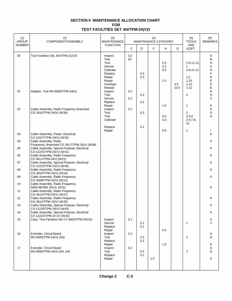
SECTION II MAINTENANCE ALLOCATION CHARTFOR
TEST FACILITIES SET AN/TPM-24(V)3
(1) (2) (3) (4) (5) (6)GROUP COMPONENT/ASSEMBLY MAINTENANCE MAINTENANCE CATEGORY TOOLS REMARKS
NUMBER FUNCTION ANDC O F H D EQPT.
00 Test Facilities Set, AN/TPM-21(V)3 Inspect 0.2 ATest 03 BTest 0.5 2-9,11,12, GService 0.2 1 CCalibrate 0.5 4-9,11,12 HReplace 0.3 FRepair 0.3 1,2 DRepair 1.0 1,10 EOverhaul 4.0 1-12 ERebuild 10.0 1-12 E
01 Adapter, Test MX-8565/TPM-24(V) Inspect 0.2 ATest 0.3 2 DService 0.2 CReplace 0.2Repair 1.0 1 E
02 Cable Assembly, Radio Frequency Branched Inspect 0.2 ACG-3616/TPM-24(V) (W39) Test 0.3 2 D
Test 0.5 2,3,4 GCalibrate 0.3 2-4,7,9,
12Replace 0.2Repair 0.5 1 I
03 Cable Assembly, Power, Electrical, KCX-12227/TPM-24(V) (W32)
04 Cable Assembly, Radio KFrequency, Branched CG 3617/TPM-24(V) (W48)
05 Cable Assembly, Special Purpose, Electrical KCX-12223/TPM-24(V) (W41)
06 Cable Assembly, Radio Frequency KCX-3611/TPM-24V) (W21)
07 Cable Assembly, Special Purpose, Electrical KCX-12222/TPM-24(V) (W40)
08 Cable Assembly, Radio Frequency KCG-3610/TPM-24(V) (W16)
09 Cable Assembly, Radio Frequency KCG-3608/TPM-24(V) (W13)
10 Cable Assembly, Radio FrequencySMD-687981 (W14, W15) K
11 Cable Assembly, Radio FrequencyCG-3613/TPM-24(V) (W47)
12 Cable Assembly, Radio Frequency KCG-3612/TPM-24(V) (W45)
13 Cable Assembly, Special Purpose, Electrical KCX-12225/TPM-24(V) (W43)
14 Cable Assembly, Special Purpose, Electrical KCX-12224/TPM-24 (V) (W42)
15 Case, Test Facilities Set CY-6825/TPM-24(V)3 Inspect 0.1 AService 0.2 1 CReplace 0.1Repair 0.5
16 Extender, Circuit Board Inspect 0.2 AMX-8563/TPM-24(V) (A5) Test 0.3 2 D
Replace 0.2Repair 1.0 E
17 Extender, Circuit Board Inspect 0.2 AMX-8560/TPM-24(V) (A3, A4) Test 0.3 2 D
Replace 0.2Repair 1.0 E
Change 2 C-3
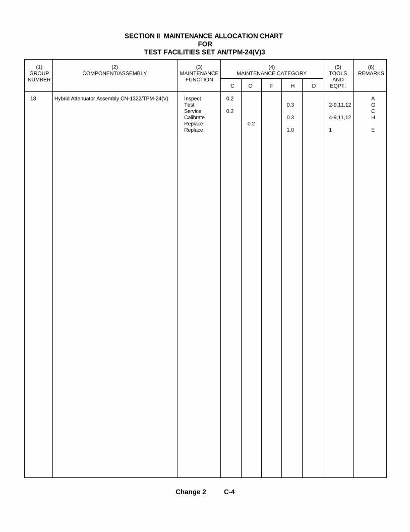
SECTION II MAINTENANCE ALLOCATION CHARTFOR
TEST FACILITIES SET AN/TPM-24(V)3
(1) (2) (3) (4) (5) (6)GROUP COMPONENT/ASSEMBLY MAINTENANCE MAINTENANCE CATEGORY TOOLS REMARKS
NUMBER FUNCTION ANDC O F H D EQPT.
18 Hybrid Attenuator Assembly CN-1322/TPM-24(V) Inspect 0.2 ATest 0.3 2-9,11,12 GService 0.2 CCalibrate 0.3 4-9,11,12 HReplace 0.2Replace 1.0 1 E
Change 2 C-4

SECTION III TOOL AND TEST EQUIPMENT REQUIREMENTFOR
TEST FACILITIES SET AN/TPM-24(V)3
TOOL OR TEST MAINTENANCE NATIONAL/NATO TOOL NUMBEREQUIPMENT CATEGORY NOMENCLATURE STOCK NUMBERREF CODE
1 O, H, D Tool Kit, Electronic Equipment TK-100/G 5180-00-605-0079
2 O, H, D Multimeter AN/FSM-6B 6625-00-957-4374
3 H, D Ohmmeter ZM-21A/U 6625-00-643-1030
4 H, D Signal Generator SG-340A/G 6625-00-542-1292
5 H, D Low-Pass Band Pass Filter HP 360C 5915-00-503-0533
6 H, D Attenuator, Precision Step, Alfred Model E101 6625-00-061-0230
7 H, D Indicator, Standing Wave Ratio IM-175B/U* 6625-00-682-3480
8 H, D Crystal Detector, HP 423A 4940-00-871-8508
9 H, D Slotted Line, IM-92/U 6625-00-356-0314
10 H, D Repair Kit, Printed Wiring Board, MK-772/U 5999-00-757-7042
11 H, D Termination, 50 Oh , Micro Lab/FKR TA-6MN (2 required) 6625-00-137-5900
12 H, D Adapters, UG-201A/U 5935-00-259-0205
* Replaces the AN/UPM-108A in all maintenance procedures inTM 11-6625-2398-15-3.
Change 2 C-5

SECTION IV. REMARKS
ReferenceCode Remarks
A Visual
B Operational
C Preventive Maintenance
D Continuity check of cables, extender boards, and Front panel Test Adapter
E Shop Facilities
F End item and cable assembles
G General trouble shooting, VSWR
H Hybrid Attenuator Sum Channel, Difference Channel, Attenuator Dial, Calibration ofInsertion
I Non Repairable, except for Replacement of Standard Connectors
J Calibration of Insertion Loss
K Maintenance function, Category, tools and equipment, Same as group number 02.
L Maintenance Function, Category, tools and Equipment, Same as group number 1801.
Change 2 C-6

TM 11-6625-2398-15-3
APPENDIX DORGANIZATIONAL, DIRECT SUPPORT, GENERAL SUPPORT, ANDDEPOT MAINTENANCE REPAIR PARTS AND SPECIAL TOOLS LIST
Section I. INTRODUCTION
D-1. ScopeThis appendix lists repair parts and special tools requiredfor the performance of organizational, direct support,general support, -and depot maintenance of the AN/TPM-24(V)3.D-2. GeneralThis repair parts and special tools list is divided into thefollowing sections:
a. Repair Parts for Organizational Maintenance-Section II. A list of repair parts authorized for theperformance of maintenance at the organizational level.
b. Special Tools, Test and Support Equipment forOrganizational Maintenance. Not applicable.
c. Repair Parts for Direct Support, General Support,and Depot Maintenance-Section III. A list of repair partsauthorized for the performance of maintenance at thedirect support, general support, and depot level.
d. Special Tools, Test and Support Equipment forDirect Support, General Support, and Depot Maintenance- Section IV. A list of special tools, test and supportequipment authorized for the performance ofmaintenance at the direct support, general support, anddepot level.
e. Index-Federal Stock Number Cross-Reference toFigure and Item Number or Reference DesignationSection V. A list of Federal stock numbers in ascendingnumerical sequence, followed by a list of referencenumbers appearing in ascending alphanumeric sequence,cross-referenced to the illustration figure number andreference designation.
f. Index-Reference Designation Cross-Reference toPage Number-Section VI. A list of reference designationscross-referenced to page numbers.D-3. Explanation of Columns
a. The following provides an explanation of columnsfound in the tabular listings.
(1) Source code. Indicates the manner of ac-quiring support items for maintenance repair, or overhaulof end items. Source codes are-Code ExplanationPA-Item procured and stocked for anticipated or known
usage.PB-Item procured and stocked for insurance purposes
because essentiality dictates that a minimumquantity be available in the supply systems.
PC-Item procured and stocked and which otherwise couldbe code PA except that it is deteriorative innature.
PD-Support item, excluding support equipment, procuredfor initial issue or outfitting and stocked only forsubsequent or additional initial issues or out-fittings. Not subject to automatic replenishment.
PE-Support equipment procured and stocked for initialissue or outfitting to specified maintenance repairactivities.
PF-Support equipment which will not be stocked butwhich will be centrally procured on demand.
PG-Item procured and stocked to provide for sustainedsupport for the life of the equipment. It is appliedto an item peculiar to the equipment whichbecause of probable discontinuance or shutdownof production facilities would prove uneconomicalto reproduce at a later time.
KD-An item of depot overhaul/repair kit and notpurchased separately. Depot kit defined as a kitthat provided items required at the time ofoverhaul or repair.
KF-An item of a maintenance kit and not purchasedseparately. Maintenance kit defined as a kit thatprovides an item that can be replaced atorganization or direct support or general supportlevels of maintenance.
Change 1 D-1

TM 11-6625-2398-15-3
Code ExplanationKB-Item included in both a depot overhaul/repair kit and a
maintenance kit.MO--Item to be manufactured or fabricated at
organization level.MF-Item to be manufactured or fabricated at direct
support maintenance level.MH-Item to be manufactured or fabricated at general
support maintenance level.MD-Item to be manufactured or fabricated at depot
maintenance level.AO-Item to be assembled at organizational level.AF-Item to be assembled at direct support maintenance
level.AH-Item to be assembled at general support maintenance
level.AD-Item to be assembled at depot maintenance level.XA-ltem is not procured or stocked because the
requirements for the item will result in thereplacement of the next higher assembly.
XB-Item is not procured or stocked. If not availablethrough salvage, requisition.
XC-Installation drawing, diagram instruction sheet, fieldservice drawing, that is identified bymanufacturers' part number.
XD-Support items can be requisitioned with justification.NOTE
Cannibalization or salvage may beused as a source of supply for anyitems source coded above exceptthose coded XA and aircraft supportitems as restricted by AR 700-42.
(2) Maintenance code. Maintenance codes areassigned to indicate the levels of maintenance authorizedto USE and REPAIR support items. The maintenancecodes are entered in the third and fourth positions of theUniform SMR Code Format as follows:
(a) Use (third position). The maintenancecode entered in the third position indicates the lowestmaintenance level authorized to remove, replace, anduse the support item. The maintenance code entered inthe third position indicates one of the following levels ofmaintenance.Code Application/Explanation
O-Support item is removed, replaced, used at organiza-tional level of maintenance.
Code Application/Explanation
NOTEA code "C" may be used in thisposition to denote crew or operatormaintenance performed within orga-nizational maintenance.
F-Support item is removed, replaced, used at theDirect Support maintenance level.
H-Support item is removed, replaced, used at theGeneral Support maintenance.
D-Support items that are removed, replaced, used atdepot only.
(b) Repair (fourth position). The maintenance codeentered in the fourth position indicates whether the item isto be repaired and identifies the lowest maintenance levelwith the capability to perform complete repair (i.e., allauthorized maintenance functions). When a maintenancecode is not used a dash (-) sign is entered. Formultiservice equipment/systems, or when a code isentered, this position will contain one of the followingmaintenance codes as assigned by the service(s) thatrequire the code:Code Application/Explanation
O-The lowest maintenance level capable of completerepair of the support item is the organizationallevel.
F-The lowest maintenance level capable of completerepair of the support item is direct support.
H-The lowest maintenance level capable of completerepair of the support item is general support.
D-The lowest maintenance level capable of completerepair of the support item is the depot level.
L--Repair restricted to designated Specialized RepairActivity.
Z-Nonrepairable. No repair is authorized.B-No repair is authorized. The item may be
reconditioned by adjusting, lubricating, etc., at theuser level. No parts or special tools are procuredfor the maintenance of this item.(3) Recoverability code. Recoverability codes
are assigned to support items to indicate the dispositionaction on unserviceable items. The recoverability code isentered in the fifth position of the uniform SMR CodeFormat as follows:Code Explanation
Z-Nonrepairable item. When unserviceable, condemnand dispose at the level indicated in the first digitof the maintenance code.
Change 1 D-2

TM 11-6625-2398-15-3
Code Explanation
O--Repairable item. When uneconomically repairable,condemn and dispose at organizational level.
F-Repairable item. When uneconomically repairable,condemn and dispose at the Direct Support Level.
H-Repairable item. When uneconomically repairable,condemn and dispose at the General SupportLevel.
D-Repairable item. When beyond lower level repaircapability, return to depot. Condemnation anddisposal not authorized below depot level.
L-Repairable item. Repair condemnation and disposalnot authorized below/Specialized Repair Activitylevel.
A-Item requires special handling or condemnationprocedures because of specific reasons (i.e.,precious metal content, high dollar value, criticalmaterial or hazardous material).
b. Federal Stock Number. Indicates the Federalstock number assigned to the item and will be used forrequisitioning purposes.
c. Description. Indicates the Federal item name andany additional description of the item required. A partnumber or other reference number is followed by theapplicable five-digit Federal supply code formanufacturers in parentheses.
d. Unit of Measure (U/M). A two-character alpha-betic abbreviation indicating the amount or quantity of theitem upon which the allowances are based; e.g., ft, ea, pr,etc.
e. Quantity Incorporated in Unit. Indicates thequantity of the item used in the AN/TPM-24(V)3.Subsequent appearances of the same item in the sameassembly are indicated by the letters "REF".
f. Allowances (15-Day Organizational Maintenance,SO-Day DS/GS Maintenance, 1 Year Per EquipmentContingency, and Depot Maintenance). Items authorizedfor requisition as required are identified by an asterisk inthe allowance columns.
g. Illustrations.(1) Figure number. Indicates the figure number
of the illustration in which the item is shown.(2) Item number or reference designation.
Indicates the reference designation used to identify theitem in the illustration.
D-4. Location of Repair Partsa. This appendix contains two cross reference
indexes (sec V and sec VI) to be used to locate a repairpart when either the Federal stock number, referencenumber (manufacturer's part number), or referencedesignation is known. The first column in each index isprepared in numerical or alphanumeric sequence isascending order. Where a Federal stock number is notlisted, refer to the reference number (manufacturer's partnumbers) immediately following the Federal stocknumber.
b. When the Federal stock number or referencenumber is known, follow the procedures given in (1) and(2) below.
(1) Refer to the index of Federal stock numbersand reference numbers (see V) and locate the Federalstock number or reference number. The Federal stocknumber or reference number is cross-referenced to theapplicable figure and reference designation.
(2) When the reference designation is deter-mined, refer to the reference designation index (see VI).The reference designations are listed in alpha-numericascending order and are cross-referenced to the pagenumber on which they appear in the repair parts list (sec IIor III). Refer to the page number noted in the index andlocate the reference designation in the repair parts list(col. 7b, Repair Parts for organizational Maintenance orcol. 10b, Repair Parts for Direct Support, General Supportand Depot Maintenance).
c. When the reference designation is known, followthe procedures given in b(2) above.
d. When neither the Federal stock number,reference number, nor reference designation is known,identify the part in the illustration and follow directionsgiven in c above or scrutinize column 3 of the repair partslists (see II and sec III).
D-5. Federal Supply Code for ManufacturersThe last line on the Description column indicates theapplicable Federal Supply Code for Manufacturer (FSCM)in parentheses. The FSCM is used as an element in itemidentification to designate manufacturer or distributor orGovernment agency, etc., and is identified in SB 70842.
(Next printed page is D-5)
Change 1 D-3

TM 11-6625-2398-15-3
SECTION II REPAIR PARTS FOR ORGANIZATIONAL MAINTENANCE
(1) (2) (3) (4) (5) (6) (7)SMR FEDERAL DESCRIPTION UNIT QTY 15-DAY ORGANIZATIONAL ILLUSTRATIONS
CODE STOCK OF INC MAINTENANCE ALW (a) (b)NUMBER MEAS IN FIG ITEM NO.
USABLE ON UNIT (a) (b) (c) (d) NO. OR REFERENCEReference Number & Mfr Code CODE 1-5 6-20 21-50 51-100 DESIGNATION
6625-133-7865 TEST FACILITIES SET AN/TPM-24(V)3 1-1(This item is nonexpendable)
PAOZZ 5935-862-9614 ADAPTER, CONNECTOR: EA 2 * * * * 1-6(1) CF7UG201AU (81350)
PAOZZ 5935-842-9614 ADAPTER, CONNECTOR: EA REF * * * * 1-6(1) CP8UG201AU (81350)
PAOZZ 5935-683-7892 ADAPTER, CONNECTOR: EA 3 * * * * 1-6(1) CP9UG274BU (80058)
PAOZZ 5935-683-7892 ADAPTER, CONNECTOR: EA REF * * * * 1-6(1) CP10UG274BU (80058)
PAOZZ 5935-683-7892 ADAPTER, CONNECTOR: EA REF * * * * 1-6(1) CP11UG274BU (80058)
PAOZZ 5935-177-2761 ADAPTER, CONNECTOR: EA 2 * * * * 1-6(1) CP5UG-1898/TPM -24(V)
PAOZZ 5935-177-2761 ADAPTER, CONNECTOR: EA REF * * * * 1-6(1) CP6UG-1898/TPM -24(V)
PAOZZ 5935-837-5280 ADAPTER, CONNECTOR: EA 3 * * * * 1-6(1) CP2UG-1896/TPM -2 (V)
PAOZZ 5315-837-5280 ADAPTER, CONNECTOR: EA REF * * * * 1-6(1) CP3UG-1896/TPM -24(V)
PAOZZ 5935-837-5280 ADAPTER, CONNECTOR: EA REF * * * * 1-6(1) CP4UG-1896/TPM -24(V)
PAOZZ 5935 075-7008 ADAPTER, CONNECTOR: EA 1 * * * * 1-6(1) CP1UG-1897/TPM -24(V)
PAOZZ 5985-128-0195 ATTENUATOR, FIXED EA 2 * * * * 1-6(1) AT1CN-1321/TPM -24(V)
PAOZZ 5985-128-0195 ATTENUATOR, FIXED EA REF * * * * 1-6(1) AT2CN-1321/TPM -24(V)
PAOZZ 6623-177-4489 CABLE ASSEMBLY, RADIO FREQUENCY: EA 1 * * * * 1-5(1) W13CG-3608/TPM -24(V)
PAOHH 5995-905-7194 CABLE ASSEMBLY, RADIO FREQUENCY: EA 2 * * * * 1-5(1) W14SMD657879 (80249)
PAOHH 5995-9t5-7194 CABLE ASSEMBLY, RADIO FREQUENCY: EA REF * * * * 1-5(1) W15SMD657879 (80249)
PAOHH 66253-17-4490 CABLE ASSEMBLY, RADIO FREQUENCY: EA 1 * * * * 1-5(1) W16CG-3610/TPM -24(V)
PAOHH 6625-177-4495 CABLE ASSEMBLY, POWER, ELECTRICAL: EA 1 * * * * 1-5(1) W32CX-12227/TPM -24(V)
PAOHD 6625-133-7794 CABLE ASSEMBLY, RF, BRANCHED: EA 1 * * * * 1-5(2) W39CG-3616/TPM -24(V)
PAOZZ 6625-133-7805 CABLE ASSEMBLY, SP, ELECTRICAL: EA 1 * * * * 1-5(2) W40CX-12222/TPM -24(V)
PAOZZ 6625-133-7851 CABLE ASSEMBLY, SP, ELECTRICAL: EA 1 * * * * 1-5(2) W41CX-12223/TPM -24(V)
PAOZZ 6625-133-7797 CABLE ASSEMBLY, SP, ELECTRICAL: EA 1 * * * * 1-5(2) W42CX-12224/TPM -24(V)
PAOZZ 6625-133-7796 CABLE ASSEMBLY, SP, ELECTRICAL: EA 1 * * * * 1-5(2) W43CX-12225/TPM -24(V)
PAOHH 6625-177-4493 CABLE ASSEMBLY, RADIO FREQUENCY: EA 1 * * * * 1-5(1) W45CG-3612/TPM -24(V)
PAOHH 6625-177-4494 CABLE ASSEMBLY, RADIO FREQUENCY: EA 1 * * * * 1-5(1) W47CG-3613/TPM -24(V)
PAOHD 6625-133-7793 CABLE ASSEMBLY, RF, BRANCHED: EA 1 * * * * 1-5(1) W48CG-3617/TPM -24(V)
PAOHH 6625-177-4492 CABLE ASSEMBLY, RF: EA 1 * * * * 1-5(1) W21CG-3611/TPM-24 (V)
Change 1 D-5

TM 11-6625-2398-15-3
SECTION II REPAIR PARTS FOR ORGANIZATIONAL MAINTENANCE
(1) (2) (3) (4) (5) (6) (7)SMR FEDERAL DESCRIPTION UNIT QTY 15-DAY ORGANIZATIONAL ILLUSTRATIONS
CODE STOCK OF INC MAINTENANCE ALW (a) (b)NUMBER MEAS IN FIG ITEM NO.
USABLE ON UNIT (a) (b) (c) (d) NO. OR REFERENCEReference Number & Mfr Code CODE 1-5 6-20 21-50 51-100 DESIGNATION
PAOZZ 5985-861-7854 DUMMY LOAD, ELECTRICAL: EA 2 * * * * 1-6(1) AT3DA-558/TPM-24(V)
PAOZZ 5985-861-7854 DUMMY LOAD, ELECTRICAL: EA REF * * * * 1-6(1) AT4DA-558/TPM-24(V)
PAOZZ 5950-970-1869 DUMMY LOAD, ELECTRICAL: EA 2 * * * * 1-6(1) AT5DA-559/TPM-24(V)
PAOZZ 5950-970-1869 DUMMY LOAD, ELECTRICAL: EA REF * * * * 1-6(1) AT6DA-559/TPM-24(V)
PAOZZ 6625-133-7774 EXTENDER, CIRCUIT BOARD: EA 1 * * * * 1-6(1) A5MX-8563/TPM-24(V)
PAOHH 6625-133-7806 EXTENDER, CIRCUIT BOARD: EA 2 * * * * 1-6(1) A3MX-8560/TPM-24(V)
PAOHH 6625-133-7806 EXTENDER, CIRCUIT BOARD: EA REF * * * * 1-6(1) A4MX-8560/TPM-24(V)
PAOZZ 5120-450-6767 PULLER, PRINTED WIRING BOARD: EA 1 * * * * 1-6(1) MP1SMB687971-1 (80249)
PAOZZ 5120-450-6766 PULLER, PRINTED WIRING BOARD: EA 1 * * * * 1-6(1) MP2SMB687971-2 (80249)
Change 1 D-6

TM 11-6625-2398-15-3
SECTION III REPAIR PARTS FOR DIRECT SUPPORT, GENERAL SUPPORT, AND DEPOT MAINTENANCE
(1) (2) (3) (4) (5) (6) (7) (8) (9) (10)DESCRIPTION UNIT QTY 30 DAY DS MAINT 30 DAY GS MAINT 1-YR DEPOT ILLUS-
SMR USABLE OF INC ALLOWANCE ALLOWANCE ALW PER MAINT TRATIONCODE FEDERAL ON MEAS IN EQUIP ALW PER (a) (b)INDEX STOCK CODE UNIT (a) (b) (c) (a) (b) (c) CNTGY 100 FIG. ITEMNO NUMBER REF. NUMBER & MFR CODE 1-20 21-50 51-100 1-20 21-50 51-100 EQUIP NO. NO.
6625-133-7865 TEST FACILITIES SET AN/TPM-24(v)3 1-1(This item is nonexpendable)
PAOZZ 5935-682-9614 ADAPTER, CONNECTOR: EA 2 * * * * * * * * 1-6(1) CP7UG201AU (81350)
PAOZZ 5935-842-9614 ADAPTER, CONNECTOR: EA REF * * * * * * * * 1-6(1) CP8UG201AU (81350)
PAOZZ 5935-683-7892 ADAPTER, CONNECTOR: EA 3 * * * * * * * * 1-6(1) CP9UG274BU (80058)
PAOZZ 5935-683-7892 ADAPTER, CONNECTOR: EA REF * * * * * * * * 1-6(1) CP10UG274BU (80058)
PAOZZ 5935-683-7892 ADAPTER, CONNECTOR: EA REF * * * * * * * * 1-6(1) CP11UG274BU (80058)
PAOZZ 5935-177-2761 ADAPTER, CONNECTOR: EA 2 * * * * * * * * 1-6(1) CP5UG-1898/TPM-24(V)
PAOZZ 5935-177-2761 ADAPTER, CONNECTOR: EA REF * * * * * * * * 1-6(1) CP6UG-1898/TPM-24(V)
PAOZZ 5935-837-5280 ADAPTER, CONNECTOR: EA 3 * * * * * * * * 1-6(1) CP2UG-1896/TPM-24(V)
PAOZZ 5935-837-5280 ADAPTER, CONNECTOR: EA REF * * * * * * * * 1-6(1) CP3UG-1896/TPM-24(V)
PAOZZ 5935-837-5280 ADAPTER, CONNECTOR: EA REF * * * * * * * * 1-6(1) CP4UG-1896/TPM-24(V)
PAOZZ 5935-075-7008 ADAPTER, CONNECTOR: EA 1 * * * * * * * * 1-6(1) CP1UG-1897/TPM-24(V)
PDOHD 5935-075-7008 ADAPTER, TEST: EA 1 * * * * * * * * 1-4 A2MX-8565/TPM-24(V)
PAMZZ 5340-664-6881 BUMPER, RUBBER: EA 4 * * * * * A2MP10711 (70485)
XANZZ CHASSIS, ELECTRICAL EQUIPMENT: EA 1 A2MP1SMD687965 (80249)
XANZZ CHASSIS, ELECTRICAL EQUIPMENT: EA 1 A2MP2SMD687965 (80249)
XANZZ CHASSIS, ELECTRICAL EQUIPMENT: EA 1 A2MP3SMD687965-1 (80249)
PANZZ 5325-806-5916 EYLET, METALLIC: EA 1 * * * * * A2H1493 (01881)
PANZZ 5310-864-5798 NUT, SELF-LOCKING, CLINCE: EA 1 * * * * * A2H2711 (70485)
PANZZ 5310-819-9188 NUT, SELF-LOCKING: EA 6 * * * * * A2H3LKS032-2 (46384)
PANZZ 5340-997-2964 CLAMP, LOOP: EA 1 * * * * * A2MP4MS21322-36 (96906)
PANZZ 5305-050-9227 SCREW, MACHINE: EA 1 * * * * * A2B4MS51957-61 (96906)
PANZZ 5935-779-8294 CONNECTOR PLUG, ELECTRICAL EA 1 * * * * * 1-4 A2P1MS116P14-19P (96906)
XDNZZ COVER, REAR: EA 1 A2MP5SMD687966 (80249)
PANZZ 5305-054-6652 SCREW, MACHINE: EA 6 * * * * * A2H5MS51957-28 (96906)
PANZZ 5340-761-1258 HANDLE, ROW: EA 2 * * * * * A2MP6MS39087-6 (96906)
PANZZ 5305-050-9229 SCREW, MACHINE: EA 4 * * * * * A2H6MS51957-63 (96906)
PANZZ 5310-933-8120 WASHER, LOCK: EA 4 * * * * * A2H7MS35338-138 (96906)
Change 1 D-7

TM 11-6625-2398-15-3
SECTION III REPAIR PARTS FOR DIRECT SUPPORT, GENERAL SUPPORT, AND DEPOT MAINTENANCE (CONTINUED)
(1) (2) (3) (4) (5) (6) (7) (8) (9) (10)DESCRIPTION UNIT QTY 30 DAY DS MAINT 30 DAY GS MAINT 1-YR DEPOT ILLUS-
SMR USABLE OF INC ALLOWANCE ALLOWANCE ALW PER MAINT TRATIONCODE FEDERAL ON MEAS IN EQUIP ALW PER (a) (b)INDEX STOCK CODE UNIT (a) (b) (c) (a) (b) (c) CNTGY 100 FIG. ITEMNO NUMBER REF. NUMBER & MFR CODE 1-20 21-50 51-100 1-20 21-50 51-100 EQUIP NO. NO.
XDHZZ INSULATION, SLEEVING, ELECTRICAL: EA 1 A2MP7RT510 (08795)
PAHZZ 5935-578-3489 JACK, TIP: EA 7 * * * * * 3-2 A2J1M516108-2A (96906)
PAHZZ 5935-578-3489 JACK, TIP: EA REF * * * * * 3-2 A2J2MS16108-2A (96906)
PAHZZ 5935-578-3489 JACK, TIP: EA REF * * * * * 3-2 A2J3MS16108-2A (96906)
PAHZZ 5935-578-3489 JACK, TIP: EA REF * * * * * 3-2 A2J4MS16108-2A (96906)
PAHZZ 5935-578-3489 JACK, TIP: EA REF * * * * * 3-2 A2J5MS16108-2A (96906)
PAHZZ 5935-578-3489 JACK, TIP: EA REF * * * * * 3-2 A2J6MS16108-2A (96906)
PAHZZ 5935-578-3489 JACK, TIP: EA REF * * * * * 3-2 A2J7MS16108-2A (96906)
PAHZZ 5935-577-236 JACK, TIP: EA 1 * * * * * 3-2 A2J8MS16108-3A (96906)
PAFZZ 5355-842-1111 KNOB: EA 1 * * * * * A2MP8MS91528-1A2B (96906)
MDHZZ PI.ATE, IDENTIFICATION: EA 1 A2MP9SMD657819-5 (80249)
PAHZZ 5310-914-9748 NUT, PLAIN, HEXACON: EA 4 * * * * * A2H8MS35649-244 (96906)
PAHZZ 5305-054-5648 SCREW, MACHINE: EA 4 * * * * * A2H9MS1957-14 (96906)
PAHZZ 5310-933-8118 WASHER LOCK: EA 4 * * * * * A2H10MS35338-135 (96906)
PAHZZ 5930-177-2778 SWITCH, ROTARY: EA 1 * * * * * 3-2 A2S1SMC657830 (80249)
PAHZZ WIRE, ELECTRICAL: FT 1 * * * * * A2W1SMB657812-20-9 (80249)
PAOZZ 5985-128-0195 ATTENUATOR, FIXED EA 2 * * * * * 1-6(1) AT1CN-1321/TPM-24(V)
PAOZZ 5985-128-0195 ATTENUATOR, FIXED EA REF * * * * * * * * 1-6(1) AT2CN-1321/TPM-24(V)
PAOZZ 6625-177-4489 CABLE ASSEMBLY, RADIO FREQUENCY: EA 1 * * * * * * * * 1-5(1) W13CC-3608/TPM-24(V)
PAOZZ 5995-905-7194 CABLE ASSEMBLY, RADIO FREQUENCY: EA 2 * * * * * * * * 1-5(1) W14SMD657879 (80249)
PAOZZ 5995-905-7194 CABLE ASSEMBLY, RADIO FREQUENCY: EA REF * * * * * * * * 1-5(1) W15SMD657879 (80249)
PAHZZ 6145-542-6092 CABLE, RADIO FREQUENCY: FT 6 * * * * * W14W1RG5BCU (81349)
PAHZZ 5935-835-0508 CONNECTOR, PLUG, ELECTRICAL: EA 4 * * * * * 1-5(1) W14P1RG88GU (80058)
PAHZZ 5935-835-0508 CONNECTOR, PLUG, ELECTRICAL: EA REF * * * * * 1-5(1) W14P2RG88GU (80058)
PAHZZ 5935-835-0508 CONNECTOR, PLUG, ELECTRICAL: EA REF * * * * * 1-5(1) W15P1RG88GU (80058)
PAHZZ 5935-835-0508 CONNECTOR, PLUG, ELECTRICAL: EA REF * * * * * 1-5(1) W15P1RG88GU (80058)
MDHZZ SLEEVE, MARKER, CABLE: EA 2 W14MP1SMC657859-12 (80249)
PAOHH 6625-177-4490 CABLE ASSEMBLY, RADIO FREQUENCY: EA 1 * * * * * * * * 1-5(1) W16CG-3610/TPM-24(V)
Change 1 D-8
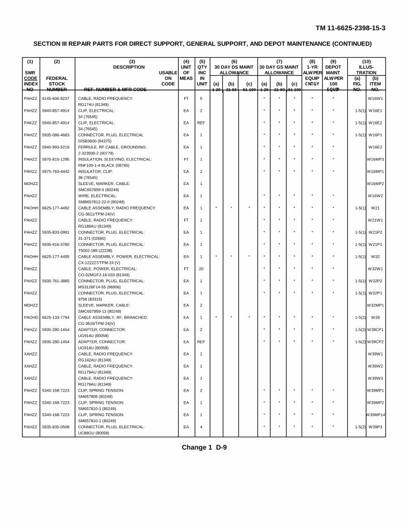
TM 11-6625-2398-15-3
SECTION III REPAIR PARTS FOR DIRECT SUPPORT, GENERAL SUPPORT, AND DEPOT MAINTENANCE (CONTINUED)
(1) (2) (3) (4) (5) (6) (7) (8) (9) (10)DESCRIPTION UNIT QTY 30 DAY DS MAINT 30 DAY GS MAINT 1-YR DEPOT ILLUS-
SMR USABLE OF INC ALLOWANCE ALLOWANCE ALW PER MAINT TRATIONCODE FEDERAL ON MEAS IN EQUIP ALW PER (a) (b)INDEX STOCK CODE UNIT (a) (b) (c) (a) (b) (c) CNTGY 100 FIG. ITEMNO NUMBER REF. NUMBER & MFR CODE 1-20 21-50 51-100 1-20 21-50 51-100 EQUIP NO. NO.
PAHZZ 6145-606-8237 CABLE, RADIO FREQUENCY: FT 5 * * * * * W16W1RG174U (81349)
PAHZZ 5940-857-4914 CLIP, ELECTRICAL: EA 2 * * * * * 1-5(1) W16E134 (76545)
PAKZZ 5940-857-4914 CLIP, ELECTRICAL: EA REF * * * * * 1-5(1) W16E234 (76545)
PAHZZ 5935-086-4683 CONNECTOR, PLUG, ELECTRICAL EA 1 * * * * * 1-5(1) W16P1025B3600 (94375)
PAHZZ 5940-993-5216 FERRULE, RF CABLE, GROUNDING: EA 1 * * * * * W16E22-323930-2 (00779)
PAHZZ 5970-815-1295 INSULATION, SLEEVING, ELECTRICAL: FT 1 * * * * * W16MP3RNF100-1-4 BLACK (08795)
PAHZZ 5975-763-4442 INSULATOR, CLIP: EA 2 * * * * * W16MP136 (76545)
MDHZZ SLEEVE, MARKER, CABLE: EA 1 W16MP2SMC657859-5 (80249)
PAHZZ WIRE, ELECTRICAL: EA 1 * * * * * W16W2SMB657812-22-0 (80249)
PAOHH 6625-177-4492 CABLE ASSEMBLY, RADIO FREQUENCY: EA 1 * * * * * * * * 1-5(1) W21CG-3611/TPM-24(V)
PAHZZ CABLE, RADIO FREQUENCY: FT 1 * * * * * W21W1RG188AU (81349)
PAHZZ 5935-833-0991 CONNECTOR, PLUG, ELECTRICAL: EA 1 * * * * * 1-5(1) W21P231-371 (02660)
PAHZZ 5935-916-3780 CONNECTOR, PLUG, ELECTRICAL: EA 1 * * * * * 1-5(1) W21P1T5002-188 (22238)
PAOHH 6625-177-4495 CABLE ASSEMBLY, POWER, ELECTRICAL: EA 1 * * * * * * * * 1-5(1) W32CX-122227/TPM-24 (V)
PAHZZ CABLE, POWER, ELECTRICAL: FT 20 * * * * * W32W1CO-02MGF2-16-033 (81349)
PAHZZ 5935-761-3885 CONNECTOR, PLUG, ELECTRICAL: EA 1 * * * * * 1-5(1) W32P2MS3126F14-55 (96906)
PAHZZ CONNECTOR, PLUG, ELECTRICAL: EA 1 * * * * * 1-5(1) W32P19758 (83315)
MDHZZ SLEEVE, MARKER, CABLE: EA 2 W32MP1SMC657859-13 (80249)
PAOHD 6625-133-7794 CABLE ASSEMBLY, RF, BRANCHED: EA 1 * * * * * * * * 1-5(2) W39CG-3616/TPM-24(V)
PAHZZ 5935-280-1454 ADAPTER, CONNECTOR: EA 2 * * * * * 1-5(2) W39CP1UG914U (80058)
PAHZZ 5935-280-1454 ADAPTER, CONNECTOR: EA REF * * * * * 1-5(2) W39CP2UG914U (80058)
XAHZZ CABLE, RADIO FREQUENCY: EA 1 W39W1RG142AU (81349)
XAHZZ CABLE, RADIO FREQUENCY: EA 1 W39W2RG179AU (81349)
XAHZZ CABLE, RADIO FREQUENCY: EA 1 W39W3RG179AU (81349)
PAHZZ 5340-168-7223 CLIP, SPRING TENSION: EA 2 * * * * * W39MP1SM657809 (80249)
PAHZZ 5340-168-7223 CLIP, SPRING TENSION: EA 1 * * * * * W39MP2SM657810-1 (80249)
PAHZZ 5340-168-7223 CLIP, SPRING TENSION: EA 1 * * * * * W39MP14SM657810-2 (80249)
PAHZZ 5935-835-0508 CONNECTOR, PLUG, ELECTRICAL: EA 4 * * * * * 1-5(2) W39P3UC88GU (80058)
Change 1 D-9

TM 11-6625-2398-15-3
SECTION III REPAIR PARTS FOR DIRECT SUPPORT, GENERAL SUPPORT, AND DEPOT MAINTENANCE (CONTINUED)
(1) (2) (3) (4) (5) (6) (7) (8) (9) (10)DESCRIPTION UNIT QTY 30 DAY DS MAINT 30 DAY GS MAINT 1-YR DEPOT ILLUS-
SMR USABLE OF INC ALLOWANCE ALLOWANCE ALW PER MAINT TRATIONCODE FEDERAL ON MEAS IN EQUIP ALW PER (a) (b)INDEX STOCK CODE UNIT (a) (b) (c) (a) (b) (c) CNTGY 100 FIG. ITEMNO NUMBER REF. NUMBER & MFR CODE 1-20 21-50 51-100 1-20 21-50 51-100 EQUIP NO. NO.
PAHZZ 5935-835-0508 CONNECTOR, PLUG ELECTRICAL: EA REF * * * * * 1-5(2) W39P4UG88GU (80058)
PAHZZ 5935-835-0508 CONNECTOR, PLUG ELECTRICAL: EA REF * * * * * 1-5(2) W39P5UG88GU (80058)
PAHZZ 5935-835-0508 CONNECTOR, PLUG ELECTRICAL: EA REF * * * * * 1-5(2) W39P6UG88GU (80058)
XAHZZ CONNECTOR, PLUG ELECTRICAL: EA 2 W39K123007-1 (91737)
XAHZZ CONNECTOR, PLUG ELECTRICAL: EA 2 W39K269171-2 (21912)
XAHZZ CONTACT, ELECTRICAL EA 2 W39E3201145-2
XAHZZ CONTACT, ELECTRICAL EA 2 W39E4201146-2
XAHZZ CONTACT, ELECTRICAL EA 2 W39E5201144-1
XAHZZ CONTACT, ELECTRICAL EA 2 W39E6201143-1
XAHZZ FERRULE, RF CABLE, GROUNDING: EA 4 W38E7328664 (00779)
XAHZZ FERRULE, RF CABLE, GROUNDING: EA 8 W38E8328666 (00779)
XAHZZ INSERT, ELECTRICAL CONNECTION: EA 1 W39MP3SMB657800 (80249)
XAHZZ INSERT, ELECTRICAL: EA 1 W39MP4SMB657801 (80249)
XAHZZ INSERT, ELECTRICAL: EA 1 W39MP5202648-2 (00779)
XAHZZ INSERT, ELECTRICAL CONNECTION: EA 1 W39MP6202649-2 (00779)
XAHZZ INSULATION, SLEEVING, ELECTRICAL: EA 1 W39MP7RMF100-1-2 (08795)
XAHZZ SHELL, ELECTRICAL CONNECTOR: EA 1 W39MP8202287-1 (00779)
XAHZZ SHELL, ELECTRICAL CONNECTOR: EA 1 W39MP9202295-1 (00779)
XAHZZ SHELL, ELECTRICAL CONNECTOR: EA 2 W39MP101-202301-1 (00779)
XAHZZ SCREW, MACHINE: EA 8 W39W1MS35338-135 (96906)
XAHZZ WASHER, LOCK: EA 8 W39W2MS35338-135 (96906)
XAHZZ SLEEVE, MARKER, CABLE: EA 2 W39MP11SMC657859-22 (80249)
XAHZZ SLEEVE, MARKER, CABLE: EA REF W39MP12SMC657859-22 (80249)
XAHZZ SPRING, RETAINING: EA 12 W39MP13201142-2 (00779)
PAOZZ 6625-133-7805 CABLE ASSEMBLY, SF, ELECTRICAL EA 1 * * * * * * * * 1-5(2) W40CX-12222/TPM-24(V)
PAOZZ 5340-168-7223 CLIP, SPRING TENSION: EA 2 * * * * * W40P1SMB657809 (80249)
PAOZZ 5340-168-7218 CLIP, SPRING TENSION: EA 2 * * * * * W40P2SMB657810-2 (80249)
PAOZZ 6625-133-7851 CABLE ASSEMBLY, SP, ELECTRICAL: EA 1 * * * * * * * * 1-5(2) W41
Change 1 D10

TM 11-6625-2398-15-3
SECTION III REPAIR PARTS FOR DIRECT SUPPORT, GENERAL SUPPORT, AND DEPOT MAINTENANCE (CONTINUED)
(1) (2) (3) (4) (5) (6) (7) (8) (9) (10)DESCRIPTION UNIT QTY 30 DAY DS MAINT 30 DAY GS MAINT 1-YR DEPOT ILLUS-
SMR USABLE OF INC ALLOWANCE ALLOWANCE ALW PER MAINT TRATIONCODE FEDERAL ON MEAS IN EQUIP ALW PER (a) (b)INDEX STOCK CODE UNIT (a) (b) (c) (a) (b) (c) CNTGY 100 FIG. ITEMNO NUMBER REF. NUMBER & MFR CODE 1-20 21-50 51-100 1-20 21-50 51-100 EQUIP NO. NO.
PAHZZ 5340-168-7223 CLIP, SPRING TENSION: EA 2 * * * * * W41MP1SMB657809 (80249)
PAHZZ 5340-168-7218 CLIP, SPRING TENSION: EA 2 * * * * * W41MP2SMB657810-2 (80249)
PAOZZ 6625-133-7797 CABLE ASSEMBLY, SP, ELECTRICAL: EA 1 * * * * * * * * 1-5(2) W42CX-12224/TPM-24(V)
PAHZZ 5340-168-7239 CLIP, SPRING TENSION: EA 2 * * * * * W42MP1SMB657809 (80249)
PAHZZ 5340-168-7239 CLIP, SPRING TENSION: EA 2 * * * * * W42MP2SMB657810-1 (80249)
PAOZZ 6625-133-7796 CABLE ASSEMBLY, SP, ELECTRICAL: EA 1 * * * * * * * * 1-5(2) W43CX-122225/TPM-24(V)
PAHZZ 5340-168-7223 CLIP, SPRING TENSION: EA 2 * * * * * W43MP1SMB657809 (80249)
PAHZZ 5340-168-7239 CLIP, SPRING TENSION: EA 2 * * * * * W43MP2SMB657810-1 (80249)
PAOZZ 6625-177-4493 CABLE ASSEMBLY, RADIO FREQUENCY: EA 1 * * * * * * * * 1-5(1) W45CG-3612/TMP-24(V)
PAHZZ 6145-542-6092 CABLE, RADIO FREQUENCY: FT 1 * * * * * W45W1RG58CU (81349)
PAHZZ 5935-577-2281 CONNECTOR, PLUG, ELECTRICAL: EA 1 * * * * * 1-5(1) W45P2UG89CU (80058)
PAHZZ 5935-177-2799 CONNECTOR, PLUG, ELECTRICAL: EA 1 * * * * * 1-5(1) W45P1101N1802 (94375)
MDHZZ SLEEVE, MARKER, CABLE: EA 1 W45MP1SMC657859-3 (80249)
PAOZZ 6625-177-4494 CABLE ASSEMBLY, RADIO FREQUENCY: EA 1 * * * * * * * * 1-5(1) W47CG-3613/TPM-24(V)
PAHZZ 6145-542-6092 CABLE, RADIO FREQUENCY: FT 1 * * * * * W47W1RG58CU (81349)
PAHZZ 5935-577-2281 CONNECTOR, PLUG, ELECTRICAL: EA 1 * * * * * 1-5(1) W47P2UG89CU (80058)
PAHZZ 5935-177-2794 CONNECTOR, PLUG, ELECTRICAL: EA 1 * * * * * 1-5(1) W47P1101B1802 (94375)
MDHZZ SLEEVE, MARKER, CABLE: EA 1 W47MP1SMC657859-4 (80249)
PAOZZ 6625-177-4494 CABLE ASSEMBLY, RF: BRANCHED: EA 1 * * * * * * * * 1-5(1) W48CG-3617/TPM-24(V)
PAHZZ CABLE, RADIO FREQUENCY: FT 30 * * * * * W48W1RG180BU (81349)
PAHZZ CONNECTOR, PLUG, ELECTRICAL: EA 1 1-5(1) W48P1SMB657781 (80249)
PAHZZ 5935-198-4182 CONNECTOR, PLUG, ELECTRICAL: EA 5 * * * * * 1-5(1) W48P2847-B1800W (94375)
PAHZZ 5935-198-4182 CONNECTOR, PLUG, ELECTRICAL: EA REF * * * * * 1-5(1) W48P3847-B1800W (94375)
PAHZZ 5935-198-4182 CONNECTOR, PLUG, ELECTRICAL: EA REF * * * * * 1-5(1) W48P4847-B1800W (94375)
PAHZZ 5935-198-4182 CONNECTOR, PLUG, ELECTRICAL: EA REF * * * * * 1-5(1) W48P5847-B1800W (94375)
PAHZZ 5935-198-4182 CONNECTOR, PLUG, ELECTRICAL: EA REF * * * * * 1-5(1) W48P6847-B1800W (94375)
XAHZZ CONTACT, ELECTRICAL: EA 6 W48E121-33012-24 (77820)
PAHZZ 5970-914-3118 INSULATION, SLEEVING, ELECTRICAL: EA 1 * * * * * W48MP1
Change 1 D-11

TM 11-6625-2398-15-3
SECTION III REPAIR PARTS FOR DIRECT SUPPORT, GENERAL SUPPORT, AND DEPOT MAINTENANCE (CONTINUED)
(1) (2) (3) (4) (5) (6) (7) (8) (9) (10)DESCRIPTION UNIT QTY 30 DAY DS MAINT 30 DAY GS MAINT 1-YR DEPOT ILLUS-
SMR USABLE OF INC ALLOWANCE ALLOWANCE ALW PER MAINT TRATIONCODE FEDERAL ON MEAS IN EQUIP ALW PER (a) (b)INDEX STOCK CODE UNIT (a) (b) (c) (a) (b) (c) CNTGY 100 FIG. ITEMNO NUMBER REF. NUMBER & MFR CODE 1-20 21-50 51-100 1-20 21-50 51-100 EQUIP NO. NO.
PAHZZ 5970-812-2967 IDSULATION, SLEEVING, ELECTRICAL: EA 1 * * * * * W48MP3RNF100-1-2 (08795)
PAHZZ 5985-232-3071 RESISTOR, FIXED, COMPOSITION: EA 1 * * * * * W48R1HRA91-50-91OHMS (05627)
XAHZZ SLEEVE, MARKER, CABLE: EA 1 W48MP2SMC657859-27 (80249)
PDODD 6625-133-7798 CASE, TEST FACILITIES SET: EA 1 * * * * * * * * 1-2 MP4CY6825/TPM-24(V)3
XAHDD CASE, TEST FACILITIES SET EA 1 MP4MP1D8762 ALTERED (98376)
PAHZZ 5340-992-8139 CATCH, CLAMPING: EA 10 * * * * * MP4MP3ZSP2-204 (98376)
XAHZZ GUARD RAIL: EA 4 MP4MP4ZSP1-158 (98376)
XDHZZ HANDLE, BOW: EA 2 MP4MP2ZSP3-377 (98376)
XDDZZ HINGE, CONTINUOUS: EA 1 MP4MP6ZSP8-806 (98376)
PAHZZ 6625-993-0879 LATCH, PUSH BUTTON: EA 3 * * * * * MP4MP7ZSP2-2004 (98376)
XDHZZ STRAP ASSEMBLY: EA 6 MP4MP5FDK1152 (98313)
PAHZZ 4820-898-3003 VALVE, SAFETY RELIEF: EA 1 * * * * * MP4MP1ZSP6-037-4 (98376)
PAOZZ 5985-861-7856 DUMMY LOAD, ELECTRICAL: EA 2 * * * * * * * * 1-6(1) AT3DA-558/TPM-24(V)
PAOZZ 5985-861-7856 DUMMY LOAD, ELECTRICAL: EA REF * * * * * * * * 1-6(1) AT4DA-558/TPM-24(V)
PAOZZ 5950-970-1869 DUMMY LOAD, ELECTRICAL: EA 2 * * * * * * * * 1-6(1) AT5DA-559/TPM-24(V)
PAOZZ 5950-970-1869 DUMMY LOAD, ELECTRICAL: EA REF * * * * * * * * 1-6(1) AT6DA-559/TPM-24(V)
PAOZZ 6625-133-7774 EXTENDER, CIRCUIT BOARD: EA 1 * * * * * * * * 1-6(2) A5MX-8563/TPM-24(V)
PAHHH 6625-133-7606 EXTENDER, CIRCUIT BOARD: EA 2 * * * * * 1-6(2) A3MX-8560/TPM-24(V)
PAHHH 6625-133-7606 EXTENDER, CIRCUIT BOARD: EA REF * * * * * 1-6(2) A4MX-8560/TPM-24(V)
PAHZZ 5935-878-6410 CONNECTOR, RECEPTACLE, ELEC: EA 1 * * * * * 1-6(2) A3J4560013PCGD22 (95213)
PAHZZ 5935-131-9693 JACK, TIP: EA 44 * * * * * 1-6(2) A3J1M39024-11-03 (96906)
PAHZZ 5935-131-9693 JACK, TIP: EA REF * * * * * 1-6(2) A3J2M39024-11-03 (96906)
PAHZZ 5935-131-9693 JACK, TIP: EA REF * * * * * 1-6(2) A3J3M39024-11-03 (96906)
PAHZZ 5935-131-9693 JACK, TIP: EA REF * * * * * 1-6(2) A3J4M39024-11-03 (96906)
PAHZZ 5935-131-9693 JACK, TIP: EA REF * * * * * 1-6(2) A3J5M39024-11-03 (96906)
PAHZZ 5935-131-9693 JACK, TIP: EA REF * * * * * 1-6(2) A3J6M39024-11-03 (96906)
PAHZZ 5935-131-9693 JACK, TIP: EA REF * * * * * 1-6(2) A3J6M39024-11-03 (96906)
PAHZZ 5935-131-9693 JACK, TIP: EA REF * * * * * 1-6(2) A3J6M39024-11-03 (96906)
Change 1 D-12

TM 11-6625-2398-15-3
SECTION III REPAIR PARTS FOR DIRECT SUPPORT, GENERAL SUPPORT, AND DEPOT MAINTENANCE (CONTINUED)
(1) (2) (3) (4) (5) (6) (7) (8) (9) (10)DESCRIPTION UNIT QTY 30 DAY DS MAINT 30 DAY GS MAINT 1-YR DEPOT ILLUS-
SMR USABLE OF INC ALLOWANCE ALLOWANCE ALW PER MAINT TRATIONCODE FEDERAL ON MEAS IN EQUIP ALW PER (a) (b)INDEX STOCK CODE UNIT (a) (b) (c) (a) (b) (c) CNTGY 100 FIG. ITEMNO NUMBER REF. NUMBER & MFR CODE 1-20 21-50 51-100 1-20 21-50 51-100 EQUIP NO. NO.
PAHZZ 5935-131-9693 JACK, TIP: EA REF * * * * * 1-6(2) A3J9M39024-11-03 (96906)
PAHZZ 5935-131-9693 JACK, TIP: EA REF * * * * * 1-6(2) A3J10M39024-11-03 (96906)
PAHZZ 5935-131-9693 JACK, TIP: EA REF * * * * * 1-6(2) A3J11M39024-11-03 (96906)
PAHZZ 5935-131-9693 JACK, TIP: EA REF * * * * * 1-6(2) A3J12M39024-11-03 (96906)
PAHZZ 5935-131-9693 JACK, TIP: EA REF * * * * * 1-6(2) A3J13M39024-11-03 (96906)
PAHZZ 5935-131-9693 JACK, TIP: EA REF * * * * * 1-6(2) A3J14M39024-11-03 (96906)
PAHZZ 5935-131-9693 JACK, TIP: EA REF * * * * * 1-6(2) A3J15M39024-11-03 (96906)
PAHZZ 5935-131-9693 JACK, TIP: EA REF * * * * * 1-6(2) A3J16M39024-11-03 (96906)
PAHZZ 5935-131-9693 JACK, TIP: EA REF * * * * * 1-6(2) A3J17M39024-11-03 (96906)
PAHZZ 5935-131-9693 JACK, TIP: EA REF * * * * * 1-6(2) A3J18M39024-11-03 (96906)
PAHZZ 5935-131-9693 JACK, TIP: EA REF * * * * * 1-6(2) A3J19M39024-11-03 (96906)
PAHZZ 5935-131-9693 JACK, TIP: EA REF * * * * * 1-6(2) A3J20M39024-11-03 (96906)
PAHZZ 5935-131-9693 JACK, TIP: EA REF * * * * * 1-6(2) A3J21M39024-11-03 (96906)
PAHZZ 5935-131-9693 JACK, TIP: EA REF * * * * * 1-6(2) A3J22M39024-11-03 (96906)
PAHZZ 5935-131-9693 JACK, TIP: EA REF * * * * * 1-6(2) A3J23M39024-11-03 (96906)
PAHZZ 5935-131-9693 JACK, TIP: EA REF * * * * * 1-6(2) A3J24M39024-11-03 (96906)
PAHZZ 5935-131-9693 JACK, TIP: EA REF * * * * * 1-6(2) A3J25M39024-11-03 (96906)
PAHZZ 5935-131-9693 JACK, TIP: EA REF * * * * * 1-6(2) A3J26M39024-11-03 (96906)
PAHZZ 5935-131-9693 JACK, TIP: EA REF * * * * * 1-6(2) A3J27M39024-11-03 (96906)
PAHZZ 5935-131-9693 JACK, TIP: EA REF * * * * * 1-6(2) A3J28M39024-11-03 (96906)
PAHZZ 5935-131-9693 JACK, TIP: EA REF * * * * * 1-6(2) A3J29M39024-11-03 (96906)
PAHZZ 5935-131-9693 JACK, TIP: EA REF * * * * * 1-6(2) A3J30M39024-11-03 (96906)
PAHZZ 5935-131-9693 JACK, TIP: EA REF * * * * * 1-6(2) A3J31M39024-11-03 (96906)
PAHZZ 5935-131-9693 JACK, TIP: EA REF * * * * * 1-6(2) A3J32M39024-11-03 (96906)
PAHZZ 5935-131-9693 JACK, TIP: EA REF * * * * * 1-6(2) A3J33M39024-11-03 (96906)
PAHZZ 5935-131-9693 JACK, TIP: EA REF * * * * * 1-6(2) A3J34M39024-11-03 (96906)
PAHZZ 5935-131-9693 JACK, TIP: EA REF * * * * * 1-6(2) A3J35M39024-11-03 (96906)
PAHZZ 5935-131-9693 JACK, TIP: EA REF * * * * * 1-6(2) A3J36M39024-11-03 (96906)
Change 1 D-13

TM 11-6625-2398-15-3
SECTION III REPAIR PARTS FOR DIRECT SUPPORT, GENERAL SUPPORT, AND DEPOT MAINTENANCE (CONTINUED)
(1) (2) (3) (4) (5) (6) (7) (8) (9) (10)DESCRIPTION UNIT QTY 30 DAY DS MAINT 30 DAY GS MAINT 1-YR DEPOT ILLUS-
SMR USABLE OF INC ALLOWANCE ALLOWANCE ALW PER MAINT TRATIONCODE FEDERAL ON MEAS IN EQUIP ALW PER (a) (b)INDEX STOCK CODE UNIT (a) (b) (c) (a) (b) (c) CNTGY 100 FIG. ITEMNO NUMBER REF. NUMBER & MFR CODE 1-20 21-50 51-100 1-20 21-50 51-100 EQUIP NO. NO.
PAHZZ 5935-131-9693 JACK, TIP: EA REF * * * * * 1-6(2) A3J37M39024-11-03 (96906)
PAHZZ 5935-131-9693 JACK, TIP: EA REF * * * * * 1-6(2) A3J38M39024-11-03 (96906)
PAHZZ 5935-131-9693 JACK, TIP: EA REF * * * * * 1-6(2) A3J39M39024-11-03 (96906)
PAHZZ 5935-131-9693 JACK, TIP: EA REF * * * * * 1-6(2) A3J40M39024-11-03 (96906)
PAHZZ 5935-131-9693 JACK, TIP: EA REF * * * * * 1-6(2) A3J41M39024-11-03 (96906)
PAHZZ 5935-131-9693 JACK, TIP: EA REF * * * * * 1-6(2) A3J42M39024-11-03 (96906)
PAHZZ 5935-131-9693 JACK, TIP: EA REF * * * * * 1-6(2) A3J43M39024-11-03 (96906)
PAHZZ 5935-131-9693 JACK, TIP: EA REF * * * * * 1-6(2) A3J44M39024-11-03 (96906)
XAHZZ PRINTED WIRING BOARD: EA 1 A3TB1SMD687958 (80249)
PDOHD 5985-177-2939 HYBRID ATTENUATOR ASSEMBLY: EA 1 * * * * * * * * 1-3 A1CM-1322/TPM-24P
PAHZZ 5305-054-6670 SCREW, MACHINE: EA 10 * * * * * A1M1MS51957-45 (96906)
PAHZZ 5310-685-3744 WASHER, FLAT: EA 10 * * * * * A1M2AN960C8 (88044)
PAHZZ 5935-904-4050 ADAPTER, CONNECTOR: EA 2 * * * * * 7-1 A1CP1MS90156-270 (96906)
PAHZZ 5935-904-4050 ADAPTER, CONNECTOR: EA REF * * * * * 7-1 A1CP2MS90156-270 (96906)
PAHZZ 5935-295-6295 ADAPTER, CONNECTOR: EA 2 * * * * * A1CP3UG606U (80058)
PAHZZ 5935-295-6295 ADAPTER, CONNECTOR: EA REF * * * * * A1CP4UG606U (80058)
PAHZZ 6625-042-8084 ATTENUATOR, VARIABLE: EA 1 * * * * * 3-1 A1AT1AU46A1NC1 (12457)
PAHZZ 5305-054-6652 SCREW, MACHINE: EA 4 * * * * * A1M3MS51957-28 (96906)
PAHZZ 5310-531-9514 WASHER, FLAT: EA 4 * * * * * A1M4AN960C6 (88044)
PAHZZ 5310-929-6395 WASHER, FLAT: EA 4 * * * * * A1M5MS35338-136 (96906)
XAHZZ BRACKET, HYBRID JUNCTION: EA 1 A1MP1SMC688016 (80249)
XAHZZ BRACKET, HYBRID JUNCTION: EA 1 A1MP2SMC688016 (80249)
PAHZZ 5310-819-9188 NUT, SELF-LOCKING, CLINCH: EA 4 A1M6LKS632-2 (46384)
PAHZZ 5305-054-6652 SCREW, MACHINE: EA 4 A1M7MS51957-28 (96906)
PAHZZ CLAMP, LOOP: EA 1 A1MP3MP4M (09922)
PAHZZ 5310-934-9748 NUT, PLAIN, HEXAGON EA 1 A1M8MS35649-244 (96906)
PAHZZ 5305-054-5651 SCREW, MACHINE: EA 1 A1M9MS51957-17 (96906)
PAHZZ WASHER, FLAT: EA 1 A1M10AM960C4 (88044)
Change 1 D-14

TM 11-6625-2398-15-3
SECTION III REPAIR PARTS FOR DIRECT SUPPORT, GENERAL SUPPORT, AND DEPOT MAINTENANCE (CONTINUED)
(1) (2) (3) (4) (5) (6) (7) (8) (9) (10)DESCRIPTION UNIT QTY 30 DAY DS MAINT 30 DAY GS MAINT 1-YR DEPOT ILLUS-
SMR USABLE OF INC ALLOWANCE ALLOWANCE ALW PER MAINT TRATIONCODE FEDERAL ON MEAS IN EQUIP ALW PER (a) (b)INDEX STOCK CODE UNIT (a) (b) (c) (a) (b) (c) CNTGY 100 FIG. ITEMNO NUMBER REF. NUMBER & MFR CODE 1-20 21-50 51-100 1-20 21-50 51-100 EQUIP NO. NO.
PAHZZ 5310-933-8118 WASHER, LOCK: EA 1 * * * * * A1M11MS35338-135 (96906)
MHHHH CABLE ASSEMBLY, RADIO FREQUENCY: EA 2 A1W4,A1W5SMC688010 (80249)
PAHZZ 6145-542-6092 CABLE, RADIO FREQUENCY: FT 1 * * * * * A1W4P1RG58CU (81349)
PAHZZ 5935-850-8876 CONNECTOR, PLUG, ELECTRICAL: EA 1 * * * * * A1W4P2UG909AU (81349)
PAHZZ 5935-760-1767 CONNECTOR, PLUG, ELECTRICAL: EA 1 * * * * * A1W4P2101N2800 (94375)
XAHZZ SLEEVE, MARKER, CABLE: EA 1 A1W4MP1SMC657859-8 (80249)
MHHHH CABLE ASSEMBLY, RADIO FREQUENCY: EA 1 7-1 A1W1SMC688011-1 (80249)
PAHZZ 6145-660-8716 CABLE, RADIO FREQUENCY: FT 8 * * * * * A1W1P1MC222U (81349)
PAHZZ 5935-932-2791 CONNECTOR, PLUG, ELECTRICAL: EA 2 * * * * * 7-1 A1W1P1UG18DU
PAHZZ 5935-932-2791 CONNECTOR, PLUG, ELECTRICAL: EA REF * * * * * 7-1 A1W1P2UG18DU
XAHZZ SLEEVE, MARKER, CABLE: EA 1 A1W1MP1SMC657859-9 (80249)
MHHHH CABLE ASSEMBLY, RADIO FREQUENCY: EA 1 7-1 A1W2SMC688011-2 (80249)
PAHZZ 6145-660-8716 CABLE, RADIO FREQUENCY: FT 1 * * * * * A1W2W1MC222U (81349)
PAHZZ 5935-932-2791 CONNECTOR, PLUG, ELECTRICAL: EA 2 * * * * * 7-1 A1W2P1UG18DU
PAHZZ 5935-932-2791 CONNECTOR, PLUG, ELECTRICAL: EA REF * * * * * 7-1 A1W2P2UG18DU
XAHZZ SLEEVE, MARKER, CABLE: EA 1 A1W2MP1SMC657859-9 (80249)
MHHHH CABLE ASSEMBLY, RADIO FREQUENCY: EA 1 A1W6SMC688013 (80249)
PAHZZ 6145-542-6092 CABLE, RADIO FREQUENCY: FT 1 * * * * * A1W6W1MC58CU (81349)
PAHZZ 5935-850-8876 CONNECTOR, PLUG, ELECTRICAL: EA 1 * * * * * A1W6P1UG909AU
PAHZZ 5935-932-2791 CONNECTOR, PLUG, ELECTRICAL: EA REF * * * * * A1W6P2101M4800A
XAHZZ SLEEVE, MARKER, CABLE: EA 1 A1W6MP1SMC657859-11 (80249)
MHHHH CABLE ASSEMBLY, RADIO FREQUENCY: EA 1 1-3 A1W3SMC688015 (80249)
PAHZZ 6145-542-6092 CABLE, RADIO FREQUENCY: FT 1 * * * * * 6-19 A1W3W1MC58CU (81349)
PAHZZ 5935-835-0508 CONNECTOR, PLUG, ELECTRICAL: EA 2 * * * * * 6-19 A1W3P1UG88CU (80058)
PAHZZ 5935-835-0508 CONNECTOR, PLUG, ELECTRICAL: EA REF * * * * * 6-19 A1W3P2UG88CU (80058)
XAHZZ SLEEVE, MARKER, CABLE: EA 1 A1W3MP1SMC657859-7 (80249)
XAHZZ CASE, ELECTRICAL EQUIPMENT: EA 1 A1MP5Z147-212888472 (19178)
PAHZZ 5340-489-6384 BUMPER, RUBBER EA 4 * * * * * A1MP6ZSP7-703 (19178)
Change 1 D-15

TM 11-6625-2398-15-3
SECTION III REPAIR PARTS FOR DIRECT SUPPORT, GENERAL SUPPORT, AND DEPOT MAINTENANCE (CONTINUED)
(1) (2) (3) (4) (5) (6) (7) (8) (9) (10)DESCRIPTION UNIT QTY 30 DAY DS MAINT 30 DAY GS MAINT 1-YR DEPOT ILLUS-
SMR USABLE OF INC ALLOWANCE ALLOWANCE ALW PER MAINT TRATIONCODE FEDERAL ON MEAS IN EQUIP ALW PER (a) (b)INDEX STOCK CODE UNIT (a) (b) (c) (a) (b) (c) CNTGY 100 FIG. ITEMNO NUMBER REF. NUMBER & MFR CODE 1-20 21-50 51-100 1-20 21-50 51-100 EQUIP NO. NO.
PAHZZ 5340-775-5978 HANDLE, BAIL: EA 1 * * * * * A1MP7ZSP3-304 (19178)
PAHZZ 4010-U49-7347 CHAIN, BEAD: EA 1 * * * * * 1-3 A1MP8NAS1201C6A168 (80205)
PAHZZ 5310-934-9748 NUT, PLAIN, HEXAGON: EA 1 * * * * * A1H12MS35649-244 (96906)
PAHZZ 5305-054-5651 SCREW, MACHINE: EA 1 * * * * * A1H13MS51957-17 (96906)
PAHZZ 5310-933-8118 WASHER, LOCK: EA 1 * * * * * A1H14MS35338-135 (96906)
XAHZZ CHASSIS, ELECTRICAL EQUIPMENT: EA 1 A1MP9SMD687991 (80249)
PAHZZ 5310-819-9188 NUT, SELF-LOCKING, CLINCH: EA 7 * * * * * A1H15LK632-2 (46384)
XAHZZ COVER, HYBRID ATTENUATOR ASSY: EA 1 A1MP10SMC687969 (80249)
PAHZZ 5305-054-6652 SCREW, MACHINE: EA 7 * * * * * A1H16MS51957-28 (96906)
PAHZZ 5985-893-1773 DUMMY LOAD, ELECTRICAL: EA 1 * * * * * 7-1 A1J4370NM (96906)
PAHZZ 5340-840-0954 HANDL.E, BOW: EA 2 * * * * * A1MP11MS39087-4 (96906)
PAHZZ 5305-059-3660 SCREW, MACHINE: EA 4 * * * * * A1H17MS51958-64 (96906)
PAHZZ 5310-933-8120 WASHER, LOCK: EA 4 * * * * * A1H18MS35338-138 (96906)
PAHZZ 5985-856-3283 HYBRID JUNCTION,.RF: EA 1 * * * * * 7-1 A1HY13032 (99899)
PAKZZ 5305-054-6670 SCREW, MACHINE: EA 4 * * * * * A1H19MS51957-45 (96906)
PAHZZ 5310-933-8119 WASHER, LOCK: EA 4 * * * * * A1H20MS35338-137 (96906)
XANZZ PANEL, FRONT: 1 A1MP12SMD687968 (80249)
PAHZZ 510-914-9759 NUT, PLAIN, HEXAGON: EA 2 * * * * * A1H21MS35649-284 (96906)
PAHZZ 5305-054-6670 SCREW, MACHINE: EA 2 * * * * * A1H22MS51957-45 (96906)
PAHZZ 5310-685-3744 WASHER, FLAT: EA 2 * * * * * A1H23AN96008 (88044)
PAHZZ 5310-933-8119 WASHER , LOCK: EA 2 * * * * * A1H24MS35338-137 (96906)
XDHZZ PLATE, CABLE REEL: EA 1 A1MP13SMC687970 (80249)
PAHZZ 5310-819-9188 NUT, SELF-LOCKING, CLINCH: EA 4 * * * * * A1H25LK632-2 (46384)
XDHZZ PLATE, CABLE REEL: EA 1 A1MP14SMC687970-1 (80249)
PAHZZ 5310-924-6652 SCREW, MACHINE: EA 8 * * * * * * A1H26MS51957-28 (96906)
MDHZZ PLATE, IDENTIFICATION: EA 1 A1MP15SMD657839-2 (50249)
PAHZZ 5310-934-9748 NUT, PLAIN, HEXAGON: EA 4 * * * * * A1H27MS35649-244 (96906)
PAHZZ 5310-934-9749 SCREW, MACHINE: EA 4 * * * * * A1H28MS51957-15 (96906)
Change 1 D-16

TM 11-6625-2398-15-3
SECTION III REPAIR PARTS FOR DIRECT SUPPORT, GENERAL SUPPORT, AND DEPOT MAINTENANCE (CONTINUED)
(1) (2) (3) (4) (5) (6) (7) (8) (9) (10)DESCRIPTION UNIT QTY 30 DAY DS MAINT 30 DAY GS MAINT 1-YR DEPOT ILLUS-
SMR USABLE OF INC ALLOWANCE ALLOWANCE ALW PER MAINT TRATIONCODE FEDERAL ON MEAS IN EQUIP ALW PER (a) (b)INDEX STOCK CODE UNIT (a) (b) (c) (a) (b) (c) CNTGY 100 FIG. ITEMNO NUMBER REF. NUMBER & MFR CODE 1-20 21-50 51-100 1-20 21-50 51-100 EQUIP NO. NO.
PAHZZ 5310-933-8118 WASHER, LOCK: EA 4 * * * * * A1H29MS35338-135 (96906)
MDHZZ PLATE, INSTRUCTION: EA 1 A1MP4SMC657856 (80249)
PAHZZ STRAP, RETAINING: EA 4 * * * * * A1MP16TA514D-12 (84971)
PAHZZ 5310-934-9761 NUT, PLAIN, HEXAGON: EA 8 * * * * * A1H30MS35649-264 (96906)
PAHZZ 5305-958-2918 SCREW, MACHINE: EA 8 * * * * * A1H31MS24693C26 (96906)
PAHZZ 5310-929-6395 WASHER, LOCK: EA 8 * * * * * A1H32MS35338-136 (96906)
PAHZZ STRAP, RETAINING: AA 4 * * * * * A1MP17TA514D16-12 (84971)
PAHZZ 5310-934-9761 NUT, PLAIN, HEXAGON: EA 8 * * * * * A1H33MS31649-264 (96906)
PAHZZ 5305-958-2918 SCREW, MACHINE: EA 8 * * * * * A1H34MS24693C26 (96906)
PAHZZ 5310-929-6395 WASHER, LOCK: EA 8 * * * * * A1H35MS35338-136 (96906)
MDHZZ PLATE, IDENTIFICATION: EA 1 M3PSMD657839-3 (80249)
PAOZZ PULLER, PRINTED WIRING BOARD: EA 1 * * * * * * * * 1-6(2) MP1SMB687971-1 (80249)
PAOZZ PULLER, PRINTED WIRING BOARD: EA 1 * * * * * * * * 1-6(2) MP2SHB687911-2 (80249)
Change 1 D-17
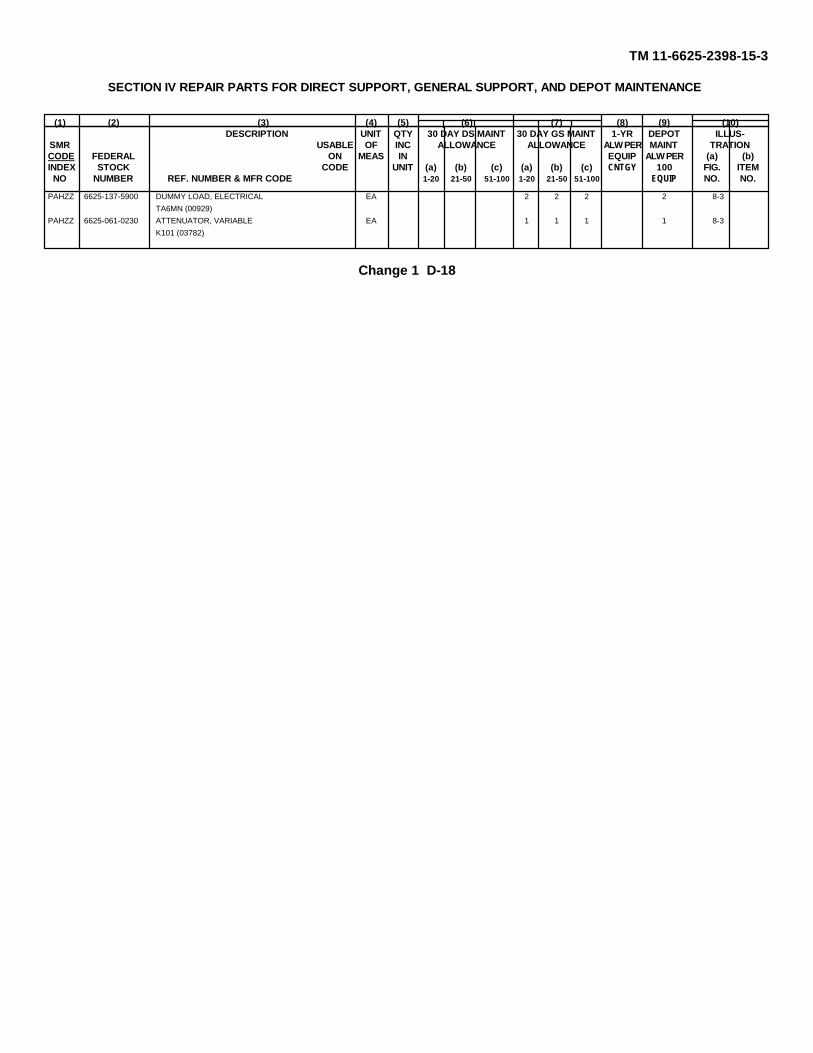
TM 11-6625-2398-15-3
SECTION IV REPAIR PARTS FOR DIRECT SUPPORT, GENERAL SUPPORT, AND DEPOT MAINTENANCE
(1) (2) (3) (4) (5) (6) (7) (8) (9) (10)DESCRIPTION UNIT QTY 30 DAY DS MAINT 30 DAY GS MAINT 1-YR DEPOT ILLUS-
SMR USABLE OF INC ALLOWANCE ALLOWANCE ALW PER MAINT TRATIONCODE FEDERAL ON MEAS IN EQUIP ALW PER (a) (b)INDEX STOCK CODE UNIT (a) (b) (c) (a) (b) (c) CNTGY 100 FIG. ITEMNO NUMBER REF. NUMBER & MFR CODE 1-20 21-50 51-100 1-20 21-50 51-100 EQUIP NO. NO.
PAHZZ 6625-137-5900 DUMMY LOAD, ELECTRICAL EA 2 2 2 2 8-3TA6MN (00929)
PAHZZ 6625-061-0230 ATTENUATOR, VARIABLE EA 1 1 1 1 8-3K101 (03782)
Change 1 D-18

TM 11-6625-2398-15-3
SECTION V INDEX-FEDERAL STOCK NUMBER AND REFERENCE NUMBER CROSS REFERENCETO FIGURE AND, ITEM NUMBER OR REFERENCE DESIGNATION
FEDERAL FIGURE ITEM NUMBER OR FEDERAL FIGURE ITEM NUMBER ORSTOCK NUMBER REF, DESIGNATION STOCK NUMBER REF, DESIGNATION
NUMBER NUMBER
4020-849-7347 1-3 A1MP8 5935-131-9693 1-6(2) A3J34820-898-3003 MP4MP1 5935-131-9693 1-6(2) A3J45305-050-9229 A2H6 5935-131-9693 1-6(2) A3J55305-050-9227 A2H4 5935-131-9693 1-6(2) A3J65305-054-5648 A2H9 5935-131-9693 1-6(2) A3J75305-054-5649 A1H28 5935-131-9693 1-6(2) A3J85305-054-5651 A1H9 5935-131-9693 1-6(2) A3J95305-054-5651 A1H13 5935-131-9693 1-6(2) A3J105305-054-6652 A1H3 5935-131-9693 1-6(2) A3J115305-054-6652 A1H77 5935-131-9693 1-6(2) A3J135305-054-6652 A1H16 5935-131-9693 1-6(2) A3J145305-054-6652 A1H26 5935-131-9693 1-6(2) A3J155305-054-6652 A2H5 5935-131-9693 1-6(2) A3J165305-054-6670 A1H1 5935-131-9693 1-6(2) A3J175305-054-6670 A1H19 5935-131-9693 1-6(2) A3J185305-054-6670 A1H22 5935-131-9693 1-6(2) A3J195305-059-3660 A1H17 5935-131-9693 1-6(2) A3J205305-958-2918 A1H31 5935-131-9693 1-6(2) A3J215305-958-2918 A1H34 5935-131-9693 1-6(2) A3J225310-531-9514 A1H4 5935-131-9693 1-6(2) A3J235310-685-3744 A1H2 5935-131-9693 1-6(2) A3J245310-685-3744 A1H23 5935-131-9693 1-6(2) A3J245310-819-9188 A2H6 5935-131-9693 1-6(2) A3J255310-819-9188 A1H15 5935-131-9693 1-6(2) A3J265310-819-9188 A1H25 5935-131-9693 1-6(2) A3J275310-819-9188 A2H3 5935-131-9693 1-6(2) A3J285310-864-5798 A2H2 5935-131-9693 1-6(2) A3J295310-929-6395 A1H5 5935-131-9693 1-6(2) A3J305310-929-6395 A1H32 5935-131-9693 1-6(2) A3J315310-929-6395 A1H35 5935-131-9693 1-6(2) A3J315310-933-8118 A1H11 5935-131-9693 1-6(2) A3J335310-933-8118 A1H14 5935-131-9693 1-6(2) A3J345310-933-8118 A1H29 5935-131-9693 1-6(2) A3J355310-933-8118 A2H10 5935-131-9693 1-6(2) A3J365310-933-8119 A1H20 5935-131-9693 1-6(2) A3J375310-933-8119 A1H24 5935-131-9693 1-6(2) A3J385310-933-8120 A1H8 5935-131-9693 1-6(2) A3J395310-933-8120 A2H7 5935-131-9693 1-6(2) A3J405310-934-9748 A1H8 5935-131-9693 1-6(2) A3J415310-934-9748 A1H12 5935-131-9693 1-6(2) A3J425310-934-9748 A1H27 5935-131-9693 1-6(2) A3J435310-934-9748 A2H8 5935-131-9693 1-6(2) A3J445310-934-9759 A1H21 5935-177-27615310-934-9761 A1H30 5935-177-2794 1-5(1) W47P15310-934-9761 A1H33 5935-177-2799 1-5(1) W45P15325-806-5916 A2H1 5935-198-4182 1-5(1) W48P25340-168-7218 W39MP14 5935-198-4182 1-5(1) W48P35340-168-7218 W40P2 5935-198-4182 1-5(1) W48P45340-168-7218 W41MP2 5935-198-4182 1-5(1) W48P55340-168-7223 W39MP1 5935-198-4182 1-5(1) W48P65340-168-7223 W40MP1 5935-233-3987 A1W6P25340-168-7223 W41MP1 5935-280-1454 1-5(2) W39C15340-168-7223 W42MP1 5935-280-1454 1-5(1) W39CP25340-168-7223 W43MP1 5935-295-6295 A1CP35340-168-7239 W39MP2 5935-295-6295 A1CP45340-168-7239 W42MP2 5935-577-2281 1-5(1) W45P25340-168-7239 W43MP2 5935-577-2281 1-5(1) W47P25340-489-6384 A1MP6 5935-577-2336 3-2 A2J85340-664-6881 A2MP10 5935-578-3489 3-2 A2J15340-761-1258 A2MP6 5935-578-3489 3-2 A2J25340-840-0954 A1MP11 5935-578-3489 3-2 A2J35340-775-5978 A1MP7 5935-578-3489 3-2 A2J45340-992-8139 MP4MP3 5935-578-3489 3-2 A2J55340-997-2964 A2MP4 5935-578-3489 3-2 A2J65355-842-3111 A2MP8 5935-578-3489 3-2 A2J65930-177-2778 A281 5935-578-3489 3-2 A2J75935-086-4683 1-5(1) W16 5935-683-7892 1-6(1) CP95935-131-9693 1-5(1) A3J1 5935-683-7892 1-6(1) CP105935-131-9693 1-5(1) A3J2 5935-683-7892 1-6(1) CP11
Change 1 D-19

TM 11-6625-2398-15-3
SECTION V INDEX-FEDERAL STOCK NUMBER AND REFERENCE NUMBER CROSS REFERENCETO FIGURE AND, ITEM NUMBER OR REFERENCE DESIGNATION (CONTINUED )
FEDERAL FIGURE ITEM NUMBER OR FEDERAL FIGURE ITEM NUMBER ORSTOCK NUMBER REF, DESIGNATION STOCK NUMBER REF, DESIGNATION
NUMBER NUMBER
5935-760-1767 A1W4P2 6625-177-4494 1-5(1) W475935-761-3885 1-5(1) W32P2 6625-177-4495 1-5(1) W325935-779-8294 1-4 A2P1 6625-993-0879 MP4MP75935-833-0991 1-5(1) W21P25935-835-0508 1-5(1) W14P1 REFERENCE MFG. FIG. REF. DESIG.5935-835-0508 1-5(1) W14P2 NO. CODE NO. OR ITEM NO.5935-835-0508 1-5(1) W15P15935-835-0508 1-5(1) W15P2 AN960C4 88044 A1H105935-835-0508 W39P3 AN960C6 88044 A1H45935-835-0508 1-5(2) W39P4 AN960C8 88044 A1H25935-835-0508 1-5(2) W39P5 AN960C8 88044 A1H235935-835-0508 1-5(2) W39P6 AU46A1NC1 12457 3-1, A1AT15935-835-0508 6-19 A1W3Pl CG-3608/TPM-24(V) 1-5(1) W135935-835-0508 6-19 A1W3P2 CG-3610/TPM-24 1-5(1) W165935-842-9614 1-6(1) CP7 CG-3611/TPM-24(V) 1-5(1) W215935-842-9614 1-6(1) CP8 CG-3612/TPM-24(V) 1-5(1) W455935-850-8876 A1W4P1 CG-3613/TPM-24(V) 1-5(1) W475935-850-8876 A1W6P1 CG-3616/TPM-24(V) 1-5(2) W395935-904-4050 7-1 A1CPl CG-3617/TPM-24(V) 1-5(1) W485935-904-4050 7-1 A1CP2 CN-1321/TPM-24(V) 1-6(1) AT15935-916-3780 1-5(1) W21P1 CN-1321/TPM-24(V) 1-6(1) AT25935-932-2791 7-1 A1W1P1 CN-1322/TPM-24(V) 1 3 A15935-932-2791 7-1 A1W1P2 CO-02CGF2-16-033 81349 W32W15935-932-2791 7-1 A1W2P1 CX-12222/TPM-24(V) 1-5(1) W405935-932-2791 7-1 AW21P2 CX-12223/TPM-24(V) 1-5(1) W415940-857-4914 1-5(1) W16E1 CX-12224/TPM-24(V) W425940-857-4914 1-5(1) W16E2 CX-12225/TPM-24(V) 1-5(1) W435935-878-6410 1-6(2) A3J45 CX-12227/TPM-24(V) 1-5(1) W325940-993-5216 W16E2 CY-6825/TPM-24(V)3 1-2 MP45950-970-1869 1-6(1) AT5 DA-558/TPM-24(V) 1-6(1) AT35950-970-1869 1-6(1) AT6 DA-558/TPM-24(V) 1-6(1) AT45970-812-2967 W48MP3 DA-559/TPM-24(V) 1-6(1) AT55970-815-1295 W16MP3 DA-559/TPM-24(V) 1-6(1) AT65970-914-3118 W48MP1 D8762ALTERED 98376 MP4MP85975-763-4442 W16MP1 FDK1152 98313 MP4MP55985-128-0195 1-6(1) AT1 HYRA91-50-910HMS 05627 W48R15985-128-0195 1-6(1) AT2 HP4N 09922 A1MP35985-177-2939 1-3 A1 LKS032-2 46S032-2 A2H25985-232-3071 W48R1 LKS632-2 46384 A2H35985-856-3283 7-1 A1HY1 LKS632-2 46384 A1H65985-861-7856 1-6(1) AT3 LKS632-2 46384 A1H155985-861-7856 1-6(1) AT4 LKS632-2 46384 A1H255985-893-1773 7-1 A1J4 MS16108-2A 96906 3-2 A2J15995-905-7194 1-5(1) W14 MS16108-2A 96906 3-2 A2J25995-905-7194 1-5(1) W15 MS16108-2A 96906 3-2 A2J36145-542-6092 W14W1 MS16108-2A 96906 3-2 A2J46145-542-6092 W45W1 MS16108-2A 96906 3-2 A2J56145-542-6092 W47W1 MS16108-2A 96906 3-2 A2J66145-542-6092 6-19 A1W3W1 MS16108-2A 96906 3-2 A2J76145-542-6092 A1W4W1 MS16108-3A 96906 3-2 A2J86145-542-6092 A1W6W1 MS21322-36 96906 A2MP46145-606-8237 W16W1 MD24693C26 96906 A1H316145-660-8716 A1W1W1 MS24693C26 96906 A1H346145-660-8716 A1W2W1 MS3116F14-19P 96906 1-4 A2P16625-042-8084 3-1 A1AT1 MS3126F14-5S 96906 1-5(1) W32P26625-133-7774 1-6(1) A5S MS35338-135 96906 W39H26625-133-7793 1-5(1) W48 MS35338-135 96906 A1H116625-133-7794 1-5(2) W39 MS35338-135 96906 A1H146625-133-7796 1-5(2) W43 MS35338-135 96906 A1H296625-133-7797 W42 MS35338-135 96906 A2H106625-133-7798 1-2 MP4 MS35338-136 96906 A1H56625-133-7806 1-6(2) A3 MS35338-136 96906 A1H326625-133-7806 1-6(2) A4 MS35338-136 96906 A1H356625-133-7851 1-5(2) W41 MS35338-137 96906 A1H206625-133-7865 MS35338-137 96906 A1H246625-177-4489 1-5(1) W13 MS35338-138 96906 A1H86625-177-4490 1-5(1) W16 MS35338-138 96906 A2H76625-177-4492 1-5(1) W21 MS35649-244 96906 A1H86625-177-4493 1-5(1) W45 MS35649-244 96906 A1H12
Change 1 D-20

TM 11-6625-2398-15-3
SECTION v INDEX-FEDERAL STOCK NUMBER AND REFERENCE NUMBER CROSS REFERENCETO FIGURE AND, ITEM NUMBER OR REFERENCE DESIGNATION (CONTINUED )
REFERENCE MFG. FIG. REF. DESIG. REFERENCE MFG. FIG. REF. DESIG.NO. CODE NO. OR ITEM NO. NO. CODE NO. OR ITEM NO.
MS35649-244 96906 A1H27 MX-8560/TPM 24(V) 1-6(2) A3MS35649-244 96906 A2H8 MX-8560/TPM-24(V) 1-6(2) A4MS35649-264 96906 A1H30 MX-8563/TPM-24(V) 1-6(1) A5MS35649-264 96906 A1H33 NAS1201C6A168 80205 1-3 A1MP8MS35649-284 96906 A1H21 RG142AU 81349 W39W1MS39024-11-03 96906 1-6(2) A3J1 RG174U 81349 W16W1MS39024-11-03 96906 1-6(2) A3J2 RG179BU 81349 W39W2MS39024-11-03 96906 1-6(2) A3J3 RG180BU 81349 W39W3MS39024-11-03 96906 1-6(2) A3J4 RG180BU 81349 W48W1MS39024-11-13 96906 1-6(2) A3J5 RG188AU 81349 W21W1MS39024-11-13 96906 1-6(2) A3J6 RG222U 81349 A1W2W1MS39024-11-03 96906 1-6(2) A3J7 RG222U 81349 A1W2W1MS39024-11-03 96906 1-6(2) A3J8 RG58CU 81349 W14W1MS39024-11-03 96906 1-6(2) A3J9 RG58CU 81349 W45W1MS39024-11-03 96906 1-6(2) A3J10 RC58CU 81349 W47W1MS39024-11-03 96906 1-6(2) A3J11 RG58CU 81349 6-19 A1W3W1MS39024-11-03 96906 1-6(2) A3J12 RG58CU 81349 A1W4W1MS39024-11-03 96906 1-6(2) A3J13 RC58CU 81349 A1W6W1MS39024-11-03 96906 1-6(2) A3J14 RNF100-1-2 08795 W39MP7MS39024-11-03 96906 1-6(2) A3J15 RNF100-1-2 08795 W48MP3MS39024-11-13 96906 1-6(2) A3J16 RNF100-1-4BLACK 08795 W16MP3MS39024-11-03 96906 1-6(2) A3J17 RNF100-3-4BLACK 08795 W48MP1MS39024-11-03 96906 1-6(2) A3J18 RT510 08795 A2H7MS39024-11-03 96906 1-6(2) A3J19 RT510 08795 A2MP7MS39024-11-03 96906 1-6(2) A3J20 SMB657781 80249 1-5(1) W48P1MS39024-11-03 96906 1-6(2) A3J21 SKB657800 80249 W39MP3MS39024-11-03 96906 1-6(2) A3J22 5SN8657801 80249 W39MP4MS39024-11-03 96906 1-6(2) AaJ23 SKB657809 80249 W39MP1MS39024-11-03 96906 1-6(2) A3J24 SMB657809 80249 W40MP1MS39024-11-03 96906 1-6(2) A3J25 SMB657809 80249 W41MP1MS39024-11-03 96906 1-6(2) A3J26 SMB657809 80249 W42MP1MS39024-11-03 96906 1-6(2) A3J27 SMB657809 80249 W43MP1MS39024-11-03 96906 1-6(2) A3J28 SMB657810-1 80249 W39MP2MS39024-11-03 96906 1-6(2) A3J29 SMB657810-1 80249 W42MP2MS39024-11-03 96906 1-6(2) A3J30 SMB657810-1 80249 W43MP2MS39024-11-03 96906 1-6(2) A3J31 SMB657810-2 80249 W39MP14MS39024-11-03 96906 1-6(2) A3J32 SMB657810-2 80249 W40P2MS39024-11-03 9b906 1-6(2) A3J33 SMB657810-2 80249 W41MP2MS39024-11-03 96906 1-6(2) A3J34 SMB657812-20-9 80249 A2W1MS39024-11-03 96906 1-6(2) A3J35 SMB657812-22-0 80249 W16W2MS39024-11-03 96906 1-6(2) A3J36 SMB687964 80249 A2MP1MS39024-11-03 96906 1-6(2) A3J37 SMB687966 80249 A2MP5MS39024-11-03 96906 1-6(2) A3J38 SMB687971-1 80249 1-6(2) MP1MS39024-11-03 96906 1-6(2) A3J39 SMB687971-2 80249 1-6(2) MP2MS39024-11-03 96906 1-6(2) A3J40 SMC657830 80249 3-2 A2S1MS39024-11-03 96906 1-6(2) A3J41 SMC657856 80249 A1MP4MS39024-11-03 96906 1-6(2) A3J42 SMC657859-10 80249 A1W2MP1MS39024-11-03 96906 1-6(2) A3J43 SMC657859-11 80249 A1W6MP1MS39024-11-03 96906 1-6(2) A3J44 SMC657859-12 80249 W14WP1MS39087-4 96906 A1MP11 SMC657859-13 80249 W32MP1MS39087-6 96906 A2MP6 SMC657859-22 80249 W39MP11MS51957-14 96906 A2H9 SMC657859-22 80249 W39MP12MS51957-15 96906 W39H1 SMC657859-27 80249 W48MP2MS51957-15 96906 A1H28 SMC657859-3 80249 W45MP1MS51957-17 96906 A1H9 SMC657859-4 80249 W47MP1MS51957-17 96906 A1H23 SMC657859-5 80249 W16MP2MS51957-28 96906 A1H3 SMC657839-7 80249 A1W3MP1MS51957-28 96906 A1H7 SMC657859-8 80249 A1W4MP1MS51957-28 96906 A1H16 SMC657859-9 80249 A1W1MP1MS51957-28 96906 A1H26 SMC687969 80249 A1MP10MS51957-28 96906 A2H5 SMC687970 80249 A1MP13MS51957-45 96906 A1H1 SMC687970-1 80249 A1MP14MS51957-45 96906 A1H19 SMC688010 80249 A1W4MS51957-45 96906 A1H22 SMC688010 80249 A1W5MS51957-61 96906 A2H4 SMC688011-1 80249 7-1 A1W1MS51957-63 96906 A2H6 SMC688011-2 80249 7-1 A1W2MS51958-64 96906 A1H17 SMC688013 80249 A1W6MS90156-270 96906 7-1 A1CP1 SMC688015 80249 1-3 A1W3MS90156-270 96906 7-1 A1CP2 SMC688016 80249 A1MP1MS91528-1A2B 96906 A2MP8 SMC688016-1 80249 A1MP2
Change 1 D-21

TM 11-6625-2398-15-3
SECTION v INDEX-FEDERAL STOCK NUMBER AND REFERENCE NUMBER CROSS REFERENCETO FIGURE AND, ITEM NUMBER OR REFERENCE DESIGNATION (CONTINUED)
REFERENCE MFG. FIG. REF. DESIG. REFERENCE MFG. FIG. REF. DESIG.NO. CODE NO. OR ITEM NO. NO. CODE NO. OR ITEM NO.
SMD657839-2 80249 A115 31-371 02660 1-5(1) W21P2SMD657839-3 80249 MP3 328664 00779 W39E7SMD657839-5 80249 A2MP9 328666 00779 W39E8SMD657879 80249 1-5(1) W14 34 76545 1-5(1) W16E1SMD657879 80249 1-5(1) W15 34 76545 1-5(1) W16E2SMD657958 80249 A3TB1 36 76543 W16MP1SMD687965 80249 A2MP2 37 99899SMD687965-1 80249 A2MP3 493 01881 A2H1SMD687968 80249 A1MP12 60013PCGD22 95238 1-6(2) A3J45SMD687991 80249 A1MP9 69171-2 21912 W39E2TA514D12-12 84971 A1MP16 711 70485 A2MP10TA514D16-12 84971 A1MP17 847-B1800W 94375 1-5(1) W48P2T5002-188 22238 1-5(1) W21P1 847-B1800W 94375 1-5(1) W48P3UG18DU 80058 7-1 A1W1P1 847-B1800W 94375 1-5(1) W48P4UG18DU 80058 7-1 A1W1P2 847-B1800W 94375 1-5(1) W48P5UG18DU 80058 701 A1W2P1 847B1800W 94375 1-5(1) W48P6UG18DU 80058 7-1 A1W2P2 9758 83315 1-5(1) W32P1U201/AU 81350 1-6(1) CP7
UG201AU 81350 1-6(1) CP8UG274BU 80058 1-6(1) CP9UG274BU 80058 1-6(1) CP10UG-274BU 80058 1-6(1) CP11UG606U 80058 A1CP3UG606U 80058 A1CP4UG88GU 80058 1-5(1) W14P1UG88GU 80058 1-5(1) W14P2UG88GU 80058 1-5(1) W15P1UG88GU 80058 1-5(1) W15P2UG88GU 80058 W39P3UG88GU 80058 1-5(2) W39P4UG88GU 80058 1-5(2) W39P5UG88GU 80058 1-5(2) W39P6UG88GU 80058 6-19 W1W3P1UG88GU 80058 6-19 W1W3P2UG89CU 80058 1-5(1) W45P2UG89CU 80058 1-5(1) W47P2UG909AU 81349 A1W4P1UG909AU 81349 A1W6P1UG914U 80058 1-5(2) W39C1UG914U 80058 1-5(2) W39C2ZSP1-158 98376 MP4MP4ZSP2-2004 98376 MP4MP7ZSP2-204 98376 MP4MP7ZSP3-304 19178 A1MP7ZSP3-377 98376 MP4MP2ZSP6-073-4 98376 MP4MP2ZSP7-703 17178 A1MP6ZSP8-806 98376 MP4MP6Z147-212BM8472 19178 A1MP5025B3600 94375 1-5(1) W16101B1802 94375 1-5(1) W47P1101N1802 94375 1-5(1) W45P1101N2800 94375 A1W4P2101N4800A 94375 A1W6P21-202301-1 00779 W39MP10201142-2 00779 W39MP10201143-1 00779 W39E6201144-1 00779 W39E5201145-2 00779 W39E3201146-2 00779 W39E4202287-1 00779 W39E3202648-2 00779 W39MP8202649-2 00779 W39MP5202795-1 00779 W39MP921-33012-24 77820 W48E123007-1 91737 W39E121-323930-2 00779 W16E23032 99899 7-1 A1HY1
Change 1 D-22

TM 11-6625-2398-15-3
SECTION VI INDEX- REFERENCE DESIGNATIONCROSS REFERENCE TO PAGE NUMBER
REFERENCE PAGE REFERENCE PAGE REFERENCE PAGEDESIGNATION NUMBER DESIGNATION NUMBER DESIGNATION NUMBER
AT1 D-5,D-8 W39MP4 D-10 A1H7 D-14AT2 D-5 .D-8 W39MP5 D-10 A1H8 D-14AT3 D-6,D-12 W39MP6 D-10 A1H9 D-14AT4 D-6,D-12 W39MP7 D-10 A1H10 D-14AT5 D-6,D-12 W39MP8 D-10 A1H11 D-15AT6 D-6,D-12 W39M9 D-10 A1H12 D-16CP7 D-5,D-7 W39MP10 D-10 A1H13 D-16CP8 D-5,D-7 W39MP11 D-10 A1H14 D-16CP9 D-5,D-7 W39MP12 D-10 A1H15 D-16CP10 D-5,D-7 W39MP13 D-10 A1H16 D-16CP11 D-5,D-7 W39MP14 D-9 A1H17 D-16MP1 D-6,D-17 W39P3 D-9 A1H19 D-16MP2 D-6,D17 W39P4 D-10 A1H20 D-16MP3 D-17 W39P5 D-10 A1H21 D-16MP4 D-12 W39P6 D-10 A1R22 D-16MP4MP1 D-12 W39W1 D-9 A1H23 D-16MP4MP2 D-12 W39W2 D-9 A1H24 D-16MP4MP3 D-12 W39W3 D-9 A1H25 D-16MP4MP4 D-12 W40 D-10 A1H26 D-16MP4MP5 D-12 W40MP1 D-10 A1H27 D-16MP4MP6 D-12 W40MP1 D-10 A1H28 D-16MP4MP7 D-12 W41 D-10 A1H29 D-17MP4MP8 D-12 W41MP1 D-11 A1H30 D-17W13 D-8 W41MP2 D-11 A1H31 D-17W14 D-8 W42 D-11 A1H32 D-17W14MP1 D-8 W41MP1 D-11 A1H33 D-17W14P1 D-8 W41MP2 D-11 A1H34 D-17W14P2 D-8 W43 D-11 A1H35 D-17W14W1 D-8 W43MP1 D-11 A1HY1 D-16W15 D-8 W43MP2 D-11 A1J4 D-16W15P1 D-8 W45 D-11 A1MP1 D-14W15P2 D-8 W45MP1 D-11 A1MP2 D-14W16 D-8 W45P1 D-11 A1MP3 D-14W16E1 D-9 W45P2 D-11 A1MP4 D-17W16E2 D-9 W45W1 D-11 A1MP5 D-15W16MP1 D-9 W47 D-11 A1MP6 D-15W16MP2 D-9 W47MP1 D-11 A1MP7 D-16W16MP3 D-9 W47P1 D-11 A1MP8 D-16W16W1 D-9 W47P2 D-11 A1MP9 D-16W16W2 D-9 W47W1 D-11 A1MP10 D-16W21 D-9 W48 D-11 A1MP11 D-16W21P1 D-9 W48E1 D-11 A1MP12 D-16W21P2 D-9 W48MP1 D-11 A1MP13 D-16W21W1 D-9 W48MP2 D-12 A1MP14 D-16W32 D-9 W48MP3 D-12 A1MP15 D-16W32MP1 D-9 W48P1 D-11 A1MP16 D-17W32P1 D-9 W48P2 D-11 A1MP17 D-17W32P2 D-9 W48P3 D-11 A1W1 D-15W32W1 D-9 W48P4 D-11 A1W1MP1 D-15W39 D-9 W48P5 D-11 A1W1P1 D-15W39CP1 D-9 W48P6 D-11 A1W1P2 D-15W39CP2 D-10 W48W1 D-12 A1W1W1 D-15W39E1 D-10 W48W1 D-11 A1W2 D-15W39E2 D-10 A1 D-14 A1W2MP1 D-15W39E3 D-10 A1AT1 D-14 A1W2P1 D-15W39E4 D-10 A1CP1 D-14 A1W2P2 D-15W39E5 D-10 A1CP2 D-14 A1W2W1 D-15W39E6 D-10 A1CP3 D-14 A1W3 D-15W39E7 D-10 A1CP4 D-14 A1W3MP1 D-15W39E8 D-10 A1H1 D-14 A1W3P1 D-15W39H1 D-10 A1H2 D-14 A1W3P2 D-15W39H2 D-9 A1H3 D-14 A1W3W1 D-15W39MP1 D-9 A1H4 D-14 A1W4 D-15W39MP2 D-10 A1H5 D-14 A1W4MP1 D-15W39MP3 D-10 A1H6 D-14 A1W4P1 D-15
Change 1 D-23

TM 11-6625-2398-15-3
SECTION VI INDEX- REFERENCE DESIGNATIONCROSS REFERENCE TO PAGE NUMBER (CONTINUED)
REFERENCE PAGE REFERENCE PAGE REFERENCE PAGEDESIGNATION NUMBER DESIGNATION NUMBER DESIGNATION NUMBER
A1W4P2 D-15 A3J25 D-13A1W4W1 D-15 A3J26 D-13A1W5 D-15 A3J27 D-13A1W6 D-15 A3J28 D-13A1W6MP1 D-15 A3J29 D-13A1W6P1 D-15 A3J30 D-13A1W6P2 D-15 A3J31 D-13A1W6W1 D-15 A3J32 D-13A2H1 D-7 A3J33 D-13A2H2 D-7 A3J34 D-13A2H3 D-7 A3J35 D-13A2H4 D-7 A3J36 D-13A2H5 D-7 A3J37 D-14A2H6 D-7 A3J38 D-14A2H7 D-7 A3J39 D-14A2H8 D-8 A3J40 D-14A2H9 D-8 A3J41 D-14A2H10 D-8 A3J42 D-14A2J1 D-8 A3J43 D-14A2J2 D-8 A3J44 D-14A2J3 D-8 A3J45 D-12A2J4 D-8 A3TB1 D-14A2J5 D-8 A4 D-6,D-12A2J6 D-8 A5 D-6,D-12A2J7 D-8A2J8 D-8A2MP1 D-7A2MP2 D-7A2MP3 D-7A2MP4 D-7A2MP5 D-7A2MP6 D-7A2MP7 D-8A2MP8 D-8A2MP9 D-8A2MP10 D-7A2MP10 D-7A2P1 D-742S1 D-8A2W1 D-8A3 D-6,D-12A3J1 D-12A3J2 D-12A3J3 D-12A3J4 D-12A3J5 D-12A3J6 D-12A3J7 D-12A3J8 D-12A3J9 D-13A3J10 D-13A3J11 D-13A3J12 D-13A3J13 D-13A3J14 D-13A3J15 D-13A3J16 D-13A3J17 D-13A3J18 D-13A3J19 D-13A3J20 D-13A3J21 D-13A3J22 D-13A3J23 D-13A3J24 D-13
Change 1 D-24

TM 11-6625-2398-15-3
INDEX
Paragraph PageAdapters .......................................................................................................................... 1-10 1-6
Cables:Connection:
W13........................................................................................................................... 3-6 6-4W16........................................................................................................................... 3-7 3-4W32 and W47............................................................................................................ 3-5 3-4W39, W40, W41, W42, and W43, (fig, 3-3) ............................................................... 3-4 3-3W48........................................................................................................................... 3-8 3-4
Continuity test, (fig, 4-1 and 8-1) ................................................................................... 4-11, 8-4 4-3, 8-2Description, (fig, 1-5)..................................................................................................... 1-9 1-4Insertion losses, (fig, 6-6 and 8-7) ................................................................................. 6-12, 8-10 6-14, 8-22Insulation resistance tests, (fig, 6-1 and 8-2) ................................................................. 6-7, 8-5 6-3, 8-5Repair, (fig, 7-1 through 7-6) ......................................................................................... 7-7 7-1
Calibration:Hybrid attenuator ATTENUATOR dial, (fig, 6-4) ............................................................ 6-10 6-11Hybrid attenuator sum channel insertion loss, (fig, 6-2) ................................................. 6-8 6-6Hybrid attenuator difference channel insertion loss, (fig, 6-3) ........................................ 6-9 6-7Insertion loss for cables W14/W15 and W39, (fig, 6-6).................................................. 6-12 6-14
Checking packed equipment ............................................................................................ 2-2 2-1Common names............................................................................................................... 1-6 1-2Components of test facilities set....................................................................................... 1-7 1-3
Demolition:Authority ....................................................................................................................... 9-3 9-1Methods........................................................................................................................ 9-4 9-1
Disassembly of test set-up ............................................................................................... 9-1 9-1Extender boards:
Cleaning ....................................................................................................................... 4-7b 4-3Continuity tests, (fig, 4-1 and 8-1) ................................................................................. 4-11, 8-4 4-3, 8-2Repair........................................................................................................................... 7-6 7-1
Forms and records ........................................................................................................... 1-3 1-1Front panel test adapter:
Continuity test, (fig, 4-1 and 8-1) ................................................................................... 4-11.8-4 4-3, 8-2Description, (fig, 1-4)..................................................................................................... 1-8c 1-4Operating controls and connectors, (fig, 3-2)................................................................. 3-2 3-1Operation...................................................................................................................... 3-9 3-5
Hybrid attenuator:Challenge monitor test .................................................................................................. 3-10a 3-6Description, (fig, 1-3)..................................................................................................... 1-8b-2 1-4, 5-1Insertion loss measurements, (fig, 6-2, 6-3, 8-3, and 8-4).............................................. 6-8, 6-9 6-6, 6-7..................................................................................................................................... 8-6, 8-7 8-10, 8-14Operation...................................................................................................................... 3-10 3-6Operating control, connectors, and cable, (fig, 3-1) ....................................................... 3-1 3-1Receiver and transmitter test configurations, (fig, 3-4) .................................................. 3-10b 3-6Technical characteristics............................................................................................... 1-5 1-2Troubleshooting ............................................................................................................ 6-6 6-2VSWR measurements, (fig, 6-5 and 8-6)....................................................................... 6-11, 8-9 6-12, 8-19
Hybrid coupler.................................................................................................................. 5-4 5-1
Index 1

TM 11-6625-2398-15-3
Paragraph Page
Index of equipment publications ....................................................................................... 1-2 1-1Installation:
Checking unpacked equipment ..................................................................................... 2-2 21Connections.................................................................................................................. 2-3b 2-1Unpacking..................................................................................................................... 2-1 2-1
Maintenance:Cleaning ....................................................................................................................... 4-7 4-3Scope ........................................................................................................................... 4-1 4-1Tools, materials, and teat equipment ............................................................................ 4-2 4-1Preventive maintenance:
Checks and services .................................................................................................. 43b 4-1Checks and services periods...................................................................................... 4-4 4-2Quarterly checks and services chart........................................................................... 4-6 4-2Systematic care ......................................................................................................... 4-3a 4-1Weekly checks and services chart ............................................................................. 4-5 4-2
Modification work orders .................................................................................................. 8-3Nomenclature................................................................................................................... 1-6 1-2Painting............................................................................................................................ 4-8 4-3Printed circuit board extractors:
Repair........................................................................................................................... 7-5 7-1Repair:
Cable ............................................................................................................................ 7-7 7-1Extender board ............................................................................................................. 7-6 7-1General......................................................................................................................... 7-1 7-1Nonrepairable components ........................................................................................... 7-2 7-1Operator's .................................................................................................................... 4-10 4-3Printed-circuit board extractors ..................................................................................... 7-5 7-1Repairable components ................................................................................................ 7-4 7-1Tools and kits................................................................................................................ 7-3 7-1
Schematic diagrams:Cable W13, (fig, 6-7)Cable W14/W15, (fig, 6-6)Cable W16, (fig, 6-9)Cable W32, (fig, 6-10)Cable W39, (fig, 6-11)Cable W40, (fig, 6-12)Cable W41, (fig, 6-13)Cable W42, (fig, 6-14)Cable W43, (fig, 6-15)Cable W45, (fig, 6-16)Cable W47, (fig, 6-17)Cable W48, (fig, 6-18)Extender board A3/A4, (fig, 6-21)Extender board A5, (fig, 6-22)Front panel test adapter, (fig, 6-20)Hybrid attenuator, (fig, 6-19)
Scope or manual.............................................................................................................. 1-1 1-1Terminations .................................................................................................................... 1-10 1-6Test facilities set, (fig, 1-1):
Common names ........................................................................................................... 1-6 1-2Components:
Cable assemblies....................................................................................................... 1-7b 1-4Major ......................................................................................................................... 1-7a 1-3Minor ......................................................................................................................... 1-7c 1-4Description of cable assemblies, figure 1-5 ................................................................ 1-9 1-4Description of major components............................................................................... 1-8 1-4Description of minor components,, (fig, 1-6)............................................................... 1-10 1-6
Connections.................................................................................................................. 2-3b 2-1Installation .................................................................................................................... 2-3a 2-1Packaging data, (fig, 2-1) , ............................................................................................ 2-1a 2-1
Index 2

TM 11-6625-2398-15-3
Paragraph Page
Purpose and use, .......................................................................................................... 1-4 1-1Repackaging................................................................................................................. 9-2 9-1Shipment ...................................................................................................................... 9-2c 9-1
Testing:Component testing:
Insulation resistance tests on cables (fig. 6-1) ............................................................ 6-7 6-3Hybrid attenuator VSW (fig, 6-5) ................................................................................ 6-11 6-12
General .support:Continuity tests on cables, extender boards, and front panel test adapt, (fig, 8-1)............. 8-4 8-2Hybrid attenuator calibration teats, (fig, 8-)....................................................................... 8-8 8-16Hybrid attenuator insertion loss measurement between RF IN/OUT and ATTEN IN/RF DIF connectors (fig, 8-4)............................................................................................. 8-7 8-14Hybrid attenuator insertion loss measurement between RF IN/OUT and RF SUMconnectors, (fig, 8-3) ........................................................................................................ 8-6 8-10Hybrid attenuator VSWR measurements.......................................................................... 8-9 8-19Insertion loss measurements for cables W14/W15 and W39, (fig, 8-7)............................. 8-10 8-22Insulation resistance tests on cables, (fig. 8-2) ................................................................. 8-5 8-5Materials .......................................................................................................................... 8-2b 8-1Modification work orders .................................................................................................. 8-3 8-2Test data summary .......................................................................................................... 8-11 8-24Test Equipment................................................................................................................ 8-2a 8-1Transit case:Cleaning........................................................................................................................... 4-7a 4-3Description, (fig, 1-2)........................................................................................................ 1-8a 1-4TroubleshootingGeneral............................................................................................................................ 4-9 4-3Isolation of trouble in hybrid attenuator............................................................................. 6-6 6-2Localization...................................................................................................................... 6-5 6-2Organization of troubleshooting procedures ..................................................................... 6-2 6-1Test equipment required .................................................................................................. 6-3 6-1Visual checks ................................................................................................................... 6-4 6-2Unpacking........................................................................................................................ 2-1 2-1
Index 3

TM 11-6625-2398-15-3
By Order of the Secretary of the Army:
W, C, WESTMORELAND,General, United States Army,
Official: Chief of Staff.VERNE L, BOWERS,Major General, United States Army,The Adjutant General.
Distribution:To be distributed in accordance with DA Form 12-32, direct and general support maintenance requirement for the
Hawk and Chaparral missile systems.
U.S, GOVERNMENT PRINTING OFFICE: 1990 - 912-912/30529


The Metric System and Equivalents
Linear Measure Liquid Measure
1 centiliter = 10 milliters = .34 fl. ounce1 centimeter = 10 millimeters = .39 inch 1 deciliter = 10 centiliters = 3.38 fl. ounces1 decimeter = 10 centimeters = 3.94 inches 1 liter = 10 deciliters = 33.81 fl. ounces1 meter = 10 decimeters = 39.37 inches 1 dekaliter = 10 liters = 2.64 gallons1 dekameter = 10 meters = 32.8 feet 1 hectoliter = 10 dekaliters = 26.42 gallons1 hectometer = 10 dekameters = 328.08 feet 1 kiloliter = 10 hectoliters = 264.18 gallons1 kilometer = 10 hectometers = 3,280.8 feet
Square MeasureWeights
1 sq. centimeter = 100 sq. millimeters = .155 sq. inch1 centigram = 10 milligrams = .15 grain 1 sq. decimeter = 100 sq. centimeters = 15.5 sq. inches1 decigram = 10 centigrams = 1.54 grains 1 sq. meter (centare) = 100 sq. decimeters = 10.76 sq. feet1 gram = 10 decigram = .035 ounce 1 sq. dekameter (are) = 100 sq. meters = 1,076.4 sq. feet1 decagram = 10 grams = .35 ounce 1 sq. hectometer (hectare) = 100 sq. dekameters = 2.47 acres1 hectogram = 10 decagrams = 3.52 ounces 1 sq. kilometer = 100 sq. hectometers = .386 sq. mile1 kilogram = 10 hectograms = 2.2 pounds1 quintal = 100 kilograms = 220.46 pounds Cubic Measure1 metric ton = 10 quintals = 1.1 short tons
1 cu. centimeter = 1000 cu. millimeters = .06 cu. inch1 cu. decimeter = 1000 cu. centimeters = 61.02 cu. inches1 cu. meter = 1000 cu. decimeters = 35.31 cu. feet
Approximate Conversion Factors
To change To Multiply by To change To Multiply by
inches centimeters 2.540 ounce-inches Newton-meters .007062feet meters .305 centimeters inches .394yards meters .914 meters feet 3.280miles kilometers 1.609 meters yards 1.094square inches square centimeters 6.451 kilometers miles .621square feet square meters .093 square centimeters square inches .155square yards square meters .836 square meters square feet 10.764square miles square kilometers 2.590 square meters square yards 1.196acres square hectometers .405 square kilometers square miles .386cubic feet cubic meters .028 square hectometers acres 2.471cubic yards cubic meters .765 cubic meters cubic feet 35.315fluid ounces milliliters 29,573 cubic meters cubic yards 1.308pints liters .473 milliliters fluid ounces .034quarts liters .946 liters pints 2.113gallons liters 3.785 liters quarts 1.057ounces grams 28.349 liters gallons .264pounds kilograms .454 grams ounces .035short tons metric tons .907 kilograms pounds 2.205pound-feet Newton-meters 1.356 metric tons short tons 1.102pound-inches Newton-meters .11296
Temperature (Exact)
°F Fahrenheit 5/9 (after Celsius °Ctemperature subtracting 32) temperature

PIN: 017624-000

This fine document...
Was brought to you by me:
Liberated Manuals -- free army and government manuals
Why do I do it? I am tired of sleazy CD-ROM sellers, who take publicly available information, slap “watermarks” and other junk on it, and sell it. Those masters of search engine manipulation make sure that their sites that sell free information, come up first in search engines. They did not create it... They did not even scan it... Why should they get your money? Why are not letting you give those free manuals to your friends?
I am setting this document FREE. This document was made by the US Government and is NOT protected by Copyright. Feel free to share, republish, sell and so on.
I am not asking you for donations, fees or handouts. If you can, please provide a link to liberatedmanuals.com, so that free manuals come up first in search engines:
<A HREF=http://www.liberatedmanuals.com/>Free Military and Government Manuals</A>
– SincerelyIgor Chudovhttp://igor.chudov.com/
– Chicago Machinery Movers