
TM 11-6130-227-40_Battery_Charger_PP-1660_1983.pdf
30
TM 11-6130-227-40 TECHNICAL MANUAL GENERAL SUPPORT MAINTENANCE MANUAL CHARGER BATTERY PP-1660/G PP-1660A/G, AND PP-1660B/G (NSN 6130-00-669-6659) HEADQUARTERS, DEPARTMENT OF THE ARMY 14 JANUARY 1983
-
Upload
wurzel1946 -
Category
Documents
-
view
218 -
download
0
Transcript of TM 11-6130-227-40_Battery_Charger_PP-1660_1983.pdf
T M 1 1 - 6 1 3 0 - 2 2 7 - 4 0
T E C H N I C A L M A N U A L
G E N E R A L S U P P O R T M A I N T E N A N C E M A N U A L
C H A R G E R B A T T E R Y
P P - 1 6 6 0 / G
P P - 1 6 6 0 A / G , A N D P P - 1 6 6 0 B / G
( N S N 6 1 3 0 - 0 0 - 6 6 9 - 6 6 5 9 )
H E A D Q U A R T E R S , D E P A R T M E N T O F T H E A R M Y1 4 J A N U A R Y 1 9 8 3
W A R N I N G
H I G H V O L T A G E
is used in this equipment
D E A T H O N C O N T A C T
may result if safety precaution
are not observed.
Be careful when working on the 115-volt ac input circuit. Use insulate d test probeswhen making voltage measurements. When working inside the equipment, be ex-
tremely care ful not to touch any internal parts whi le the battery charger is
energized. Disconnect the ac input cable before performing routing maintenance or
attempting to remove any part. Some models of the PP-1660/G and PP-1660A/G
contain selenium rectifiers. The failure of selenium rectifiers can result in theliberation of poisonous fumes and the deposit of poisonous selenium compounds.
When a rectifier burns out or arcs over, the odor is strong. Provide maximum
vent i l a t i on immed ia t e l y . AVOID INHAL ING THE FUMES. Do no t t ouch the
damaged rectifier until it has cooled.
D O N ’ T T A K E C H A N C E S ! !
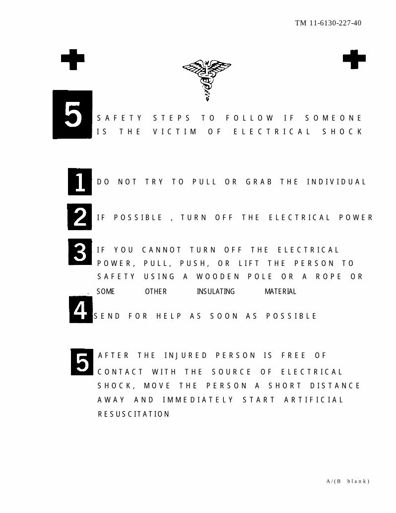
S A F E T Y S T E P S T O F O L L O W I F S O M E O N E
I S T H E V I C T I M O F E L E C T R I C A L S H O C K
TM 11-6130-227-40
D O N O T T R Y T O P U L L O R G R A B T H E I N D I V I D U A L
I F P O S S I B L E , T U R N O F F T H E E L E C T R I C A L P O W E R
I F Y O U C A N N O T T U R N O F F T H E E L E C T R I C A L
P O W E R , P U L L , P U S H , O R L I F T T H E P E R S O N T O
S A F E T Y U S I N G A W O O D E N P O L E O R A R O P E O R
SOME OTHER INSULATING MATERIAL
S E N D F O R H E L P A S S O O N A S P O S S I B L E
A F T E R T H E I N J U R E D P E R S O N I S F R E E O F
C O N T A C T W I T H T H E S O U R C E O F E L E C T R I C A L
S H O C K , M O V E T H E P E R S O N A S H O R T D I S T A N C E
A W A Y A N D I M M E D I A T E L Y S T A R T A R T I F I C I A L
R E S U S C I T A T I O N
A / ( B b l a n k )
*TM 11-6130-227-40
T E C H N I C A L M A N U A L
N o . 1 1 - 6 1 3 0 - 2 2 7 - 4 0
C HAPTER 1.
2.
3.
S E C T I O N I .
II.
III.
H E A D Q U A R T E R SD E P A R T M E N T O F T H E A R M Y
W A S H I N G T O N , DC, 14 January 1983
G E N E R A L S U P P O R T
M A I N T E N A N C E M A N U A L
C H A R G E R , B A T T E R Y P P - 1 6 6 0 / G , P P - 1 6 6 0 A / G
A N D P P - 1 6 6 0 B / G
( N S N 6 1 3 0 - 0 0 - 6 6 9 - 6 6 5 9 )
R E P O R T I N G E R R O R S A N D R E C O M M E N D I N G I M P R O V E M E N T SYou can help improve this manual. If you find any mistakes or if you know
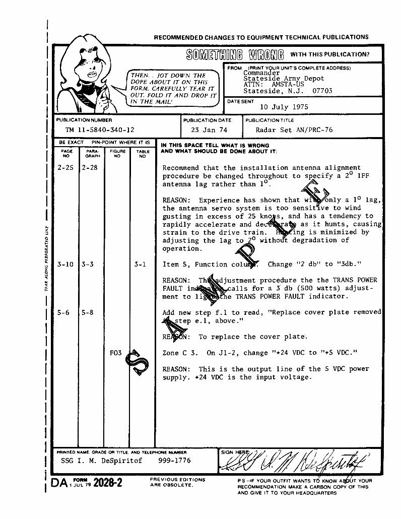
of a way to improve the procedures, please let us know. Mail your letter, DAForm 2028 (Recommended Changes to Publications and Blank Forms), or DAForm 2028-2 located in the back of this manual direct to Commander, USArmy Communications-Electronics Command and Fort Monmouth, ATTN:DRSEL-ME-MP, Fort Monmouth, NJ 07703.
In either case, a reply will be furnished direct to you.
Paragraph
INTRODUCTIONScope . . . . . . . . . . . . . . . . . . . . . . . . . . . . . . . . . . . . . . . . . . . . . . . . . . . . . . . . . . . . . . . . . . . . . . . . . . . . 1-1Consolidated Index of Army Publications and Blank Forms. . . . . . . . . . . . . . . . . . . . . . . . . . . . . . . 1 - 2Reporting Equipment Improvement Recommendations (EIR) . . . . . . . . . . . . . . . . . . . . . . . . . . . . . 1 - 3Administrative Storage . . . . . . . . . . . . . . . . . . . . . . . . . . . . . . . . . . . . . . . . . . . . . . . . . . . . . . . . . . . . . 1 - 4Destruction of Army Electronics Materiel. . . . . . . . . . . . . . . . . . . . . . . . . . . . . . . . . . . . . . . . . . . . . . 1 - 5Associated Publications . . . . . . . . . . . . . . . . . . . . . . . . . . . . . . . . . . . . . . . . . . . . . . . . . . . . . . . . . . . . 1 - 6
T H E O R YBlock Diagram Analysis . . . . . . . . . . . . . . . . . . . . . . . . . . . . . . . . . . . . . . . . . . . . . . . . . . . . . . . . . . . . 2 - 1CircuitAnalysis. . . . . . . . . . . . . . . . . . . . . . . . . . . . . . . . . . . . . . . . . . . . . . . . . . . . . . . . . . . . . . . . . . . 2 - 2CircuitAnalysis(PP-1660B/G)... . . . . . . . . . . . . . . . . . . . . . . . . . . . . . . . . . . . . . . . . . . . . . . . . . . . . 2 - 3
MAINTENANCE INSTRUCTIONS
GeneralScope of Maintenance . . . . . . . . . . . . . . . . . . . . . . . . . . . . . . . . . . . . . . . . . . . . . . . . . . . . . . . . . . . . . . 3 - 1Tools, Materials, and Test Equipment. . . . . . . . . . . . . . . . . . . . . . . . . . . . . . . . . . . . . . . . . . . . . . . . . 3 - 2Routine MaintenanceScope of Routine Maintenance . . . . . . . . . . . . . . . . . . . . . . . . . . . . . . . . . . . . . . . . . . . . . . . . . . . . . . . 3 - 3Routine Maintenance Procedures. . . . . . . . . . . . . . . . . . . . . . . . . . . . . . . . . . . . . . . . . . . . . . . . . . . . . 3 - 4Troubleshooting
Scope of Troubleshooting . . . . . . . . . . . . . . . . . . . . . . . . . . . . . . . . . . . . . . . . . . . . . . . . . . . . . . . . . . . 3 - 5Troubleshooting Procedures.. . . . . . . . . . . . . . . . . . . . . . . . . . . . . . . . . . . . . . . . . . . . . . . . . . . . . . . . 3 - 6Troubleshooting Chart . . . . . . . . . . . . . . . . . . . . . . . . . . . . . . . . . . . . . . . . . . . . . . . . . . . . . . . . . . . . . 3 - 7
Page
1-11-11-11-11-11-1
2 - 12 - 12 - 5
3 - 13 - 1
3 - 13 - 1
3 - 23 - 23 - 3
T h i s m a n u a l s u p e r s e d e s T M 1 1 - 6 1 3 0 - 2 2 7 - 4 0 , 1 6 M a r c h 1 9 7 7 .
i

TM 11-6130-227-40
Paragraph PageTroubleshooting Chart (PP-1660B/G) . . . . . . . . . . . . . . . . . . . . . . . . . . . . . . . . . . . . . . . . . . . . . . . . . 3 - 8 3 - 4
Voltage Measurements . . . . . . . . . . . . . . . . . . . . . . . . . . . . . . . . . . . . . . . . . . . . . . . . . . . . . . . . . . . . . 3 - 9 3 - 4
Resistance Measurements . . . . . . . . . . . . . . . . . . . . . . . . . . . . . . . . . . . . . . . . . . . . . . . . . . . . . . . . . . . 3-10 3-5IV. Removal and Replacement of Parts and Testing After Repair General Procedures. . . . . . . . . . . . . 3-11 3 - 5
Remove and Replacement of Parts. . . . . . . . . . . . . . . . . . . . . . . . . . . . . . . . . . . . . . . . . . . . . . . . . . . . 3 -12 3 - 5
Removal and Replacement of Parts (PP-1660B/G). . . . . . . . . . . . . . . . . . . . . . . . . . . . . . . . . . . . . . . 3 -13 3 - 6
Testing After Repair . . . . . . . . . . . . . . . . . . . . . . . . . . . . . . . . . . . . . . . . . . . . . . . . . . . . . . . . . . . . . . . 3-14 3 - 6
A P P E N D I X A . REFERENCES . . . . . . . . . . . . . . . . . . . . . . . . . . . . . . . . . . . . . . . . . . . . . . . . . . . . . . . . . . . . . . . . . . . . . . . . A - 1
i i
TM 11-6130-227-40
C H A P T E R 1
I N T R O D U C T I O N
1-1. Scope
a. T h i s m a n u a l c o v e r s g e n e r a l s u p p o r t m a i n -t e n a n c e o f B a t t e r y C h a r g e r P P - 1 6 6 0 / G ,PP-1660A/G, and PP-1660B/G. It includes in-
s t r u c t i o n s a p p r o p r i a t e t o g e n e r a l s u p p o r t f o rr o u t i n e m a i n t e n a n c e o f t h e s a m e f o rt r o u b l e s h o o t i n g , t e s t i n g , a n d r e p a i r i n g t h i sequipment , and for replac ing maintenance parts .T h e e l e c t r i c a l f u n c t i o n s o f t h e e q u i p m e n t a r e
d e s c r i b e d i n p a r a g r a p h s 2 - 1 a n d 2 - 2 . U n l e s so t h e r w i s e s p e c i f i e d h e r e i n , a l l r e f e r e n c e s t oPP-1660/G apply equal ly to the PP-1660A/G and
P P - 1 6 6 0 B / G .
b. The PP-1660/G and PP-1660A/G, except forre ference des ignat ions , are ident ica l in internalcircuit design. The PP–1660B/G uses the samereference designations as PP-1660A/G, in addition,P P - 1 6 6 0 B / G h a s a P O W E R s w i t c h , f a n s a f e t y
interlock switch, and an ac input indicator.
1-2. Consolidated Index of Army Publicationsand Blank Forms
R e f e r t o t h e l a t e s t i s s u e o f D A P a m 3 1 0 - 1 t odetermine whether there are new editions, changes,o r a d d i t i o n a l p u b l i c a t i o n s p e r t a i n i n g t o t h eequipment .
N O T EFor applicable forms and records, see TM1 1 - 6 1 3 0 - 2 2 7 - 1 2 .
1-3. Reporting Equipment ImprovementRecommendations (EIR)
I f your PP-1660(* ) /G needs improvement , le t us
know. Send us an EIR. You, the user, are the only
one who can tell us what you don’t like about yourequipment . Let us know why you don ’ t l ike thedesign. Put i t on an SF 368 (Qual i ty Def ic iency
R e p o r t ) . M a i l i t t o C o m m a n d e r , U S A r m y C o m -
m u n i c a t i o n s - E l e c t r o n i c s C o m m a n d a n d F o r tM o n m o u t h , A T T N : D R S E L - M E - M P , F o r tMonmouth, New Jersey 07703. We ’ l l send you areply.
1-4. Administrative Storage
Administrative storage of equipment issued to andused by Army activities shall be in accordance with
T M 7 4 0 - 9 0 - 1 .
1-5. Destruction of Army Electronics Materiel
Destruction of Army electronics materiel to prevent
e n e m y u s e s h a l l b e i n a c c o r d a n c e w i t h T M7 5 0 - 2 4 4 - 2 .
1-6. Associated Publications
T h e o p e r a t i n g i n s t r u c t i o n s a n d o p e r a t o r ’ s a n do r g a n i z a t i o n a l m a i n t e n a n c e i n s t r u c t i o n s f o rP P - 1 6 6 0 / G a r e c o n t a i n e d i n T M 1 1 - 6 1 3 0 - 2 2 7 - 1 2 .T M 1 1 - 6 1 3 0 - 2 2 7 - 1 2 a l s o c o v e r s m a i n t e n a n c e
a l l o c a t i o n f o r t h i s e q u i p m e n t . T M1 1 - 6 1 3 0 - 2 2 7 - 2 0 P c o n t a i n s t h e o r g a n i z a t i o n a lmaintenance repair parts and special tools list forP P - 1 6 6 0 / G . T M 1 1 - 6 1 3 0 - 2 2 7 - 2 0 P - 1 c o n t a i n s t h e
organizational maintenance repair parts and specialt o o l s l i s t f o r P P - 1 6 6 0 A / G a n d P P - 1 6 6 0 B / G . T M11-6130-227-40P contains the general support andd e p o t r e p a i r p a r t s a n d s p e c i a l t o o l s l i s t f o r
P P - 1 6 6 0 / G . T M 1 1 - 6 1 3 0 - 2 2 7 - 4 0 P - 1 c o n t a i n s t h egeneral support and depot repair parts and specialtools list for PP-1660A/G and PP-1660B/G.
1-1
T M 1 1 - 6 1 3 0 - 2 2 7 - 4 0
C H A P T E R 2
T H E O R Y
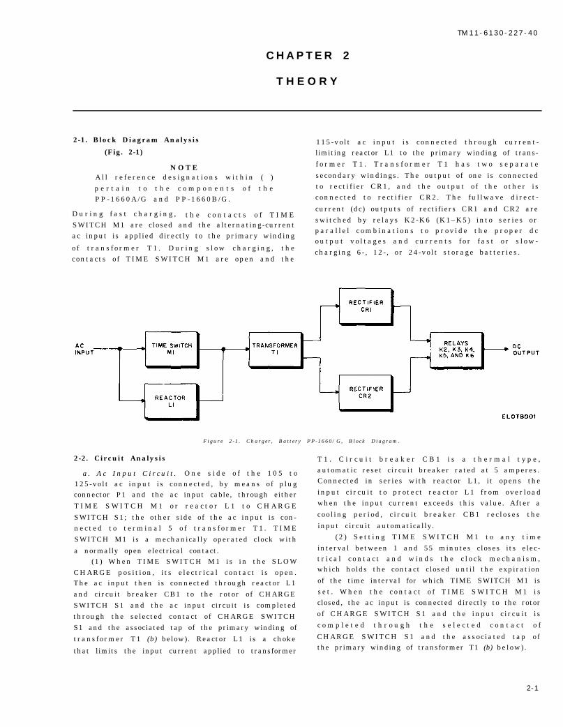
2-1. Block Diagram Analysis
(Fig. 2-1)
N O T EA l l r e f e r e n c e d e s i g n a t i o n s w i t h i n ( )p e r t a i n t o t h e c o m p o n e n t s o f t h eP P - 1 6 6 0 A / G a n d P P - 1 6 6 0 B / G .
D u r i n g f a s t c h a r g i n g , t h e c o n t a c t s o f T I M ESWITCH M1 are closed and the alternating-currentac input is applied directly to the primary winding
o f t r a n s f o r m e r T 1 . D u r i n g s l o w c h a r g i n g , t h econtacts o f TIME SWITCH M1 are open and the
115-vo l t ac input i s connected through current -limiting reactor L1 to the primary winding of trans-
f o r m e r T 1 . T r a n s f o r m e r T 1 h a s t w o s e p a r a t e
secondary windings. The output of one is connectedto rect i f ier CR1, and the output o f the other i sconnected to rect i f i er CR2. The fu l lwave d irect -
current (dc) outputs of rectifiers CR1 and CR2 areswitched by re lays K2-K6 (K1–K5) into ser ies orp a r a l l e l c o m b i n a t i o n s t o p r o v i d e t h e p r o p e r d co u t p u t v o l t a g e s a n d c u r r e n t s f o r f a s t o r s l o w -charging 6 - , 12- , or 24-vo l t s torage batter ies .
Figure 2 -1 . Charger , Bat tery PP-1660/G, Block Diagram.
2-2. Circuit Analysis T 1 . C i r c u i t b r e a k e r C B 1 i s a t h e r m a l t y p e ,
a . A c I n p u t C i r c u i t . O n e s i d e o f t h e 1 0 5 t o125-volt ac input is connected, by means o f p lugconnector P1 and the ac input cable, through either
T I M E S W I T C H M 1 o r r e a c t o r L 1 t o C H A R G E
SWITCH S1; the other side of the ac input is con-n e c t e d t o t e r m i n a l 5 o f t r a n s f o r m e r T 1 . T I M ESWITCH M1 is a mechanically operated clock with
a normally open electrical contact.(1 ) When TIME SWITCH M1 is in the SLOW
CHARGE pos i t ion , i ts e lectr i ca l contact i s open.The ac input then is connected through reactor L1and circuit breaker CB1 to the rotor of CHARGESWITCH S1 and the ac input circuit is completedthrough the selected contact of CHARGE SWITCHS1 and the associated tap of the primary winding of
transformer T1 (b) below). Reactor L1 is a choke
that limits the input current applied to transformer
automatic reset circuit breaker rated at 5 amperes.Connected in series with reactor L1, it opens the
input c i rcu i t to protect reactor L1 f rom over loadwhen the input current exceeds this value. After a
coo l ing per iod , c i rcui t breaker CB1 rec loses the
input circuit automatically.( 2 ) S e t t i n g T I M E S W I T C H M 1 t o a n y t i m e
interval between 1 and 55 minutes closes its elec-t r i c a l c o n t a c t a n d w i n d s t h e c l o c k m e c h a n i s m ,which holds the contact closed until the expiration
of the time interval for which TIME SWITCH M1 iss e t . W h e n t h e c o n t a c t o f T I M E S W I T C H M 1 i sclosed, the ac input is connected directly to the rotorof CHARGE SWITCH S1 and the input c ircuit i s
c o m p l e t e d t h r o u g h t h e s e l e c t e d c o n t a c t o f
CHARGE SWITCH S1 and the assoc iated tap ofthe primary winding of transformer T1 (b) below) .
2-1
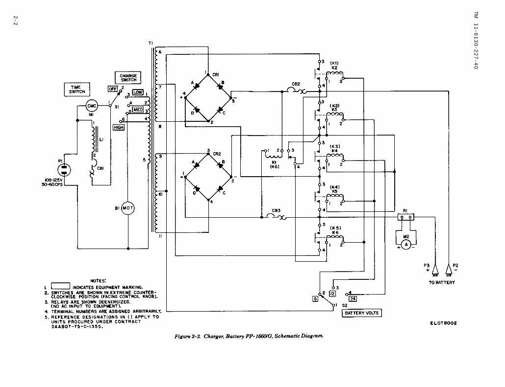
Figure 2-2.
Figure 2-2
TM
11
-61
30
-22
7-4
0
2-2
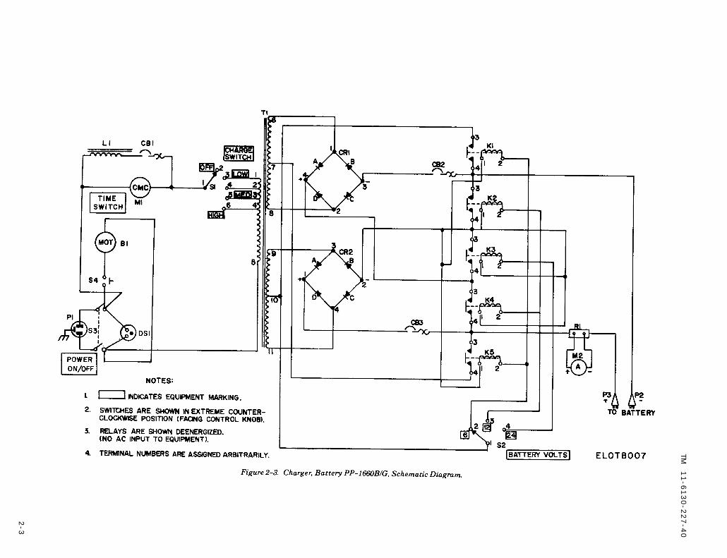
Figure 2-3.
Figure 2-3
TM
11
-61
30
-22
7-4
0
2-3

TM 11-6130-227-40
b. Transformer T1 Circuits. Transformer T1 has a
multiple-tapped primary winding and two separate,ident ical , center - tapped s e c o n d a r d w i n d i n g s .Primary taps 1, 2,3, and 4 are connected to contacts3, 4, 5, and 6, respectively, of CHARGE SWITCH
S 1 . T h u s t h e s e t t i n g o f C H A R G E S W I T C H S 1determines the number o f e f fect ive turns o f thep r i m a r y w i n d i n g o f t r a n s f o r m e r T 1 a n d c o n -sequently the voltage and current of the outputs of
t h e t w o s e c o n d a r y w i n d i n g s . T h i s a r r a n g e m e n tprovides a range of transformer outputs that per-m i t s t h e s e l e c t i o n o f a h i g h , m e d i u m , o r l o wcharging rate (c below). Blower motor B1 is con-
nected across the ac input between contact 5 o fC H A R G E S W I T C H S 1 a n d t e r m i n a l 5 o f t h eprimary winding o f transformer T1. The pr imarywinding of transformer T1 acts as an autotrans-former so that the voltage applied to blower motor
B1 increases as CHARGE SWITCH S1 is advancedrom LOW to MED to HIGH and consequently thespeed of blower motor B1 increases proportionally.Thus, a larger amount of cooling air is drawn in and
expelled by the blower as the charging rate is in-creased.
c . Rec t i f i e r Circui t s . T r a n s f o r m e r T 1 h a s t w oseparate, i d e n t i c a l s e c o n d a r y w i n d i n g s w h o s e
o u t p u t v o l t a g e i s c o n t r o l l e d b y t h e p o s i t i o n o fC H A R G E S W I T C H S 1 (b above) . The output o fsecondary winding 6-8 is connected to rectifier CR1,and the output of secondary winding 9-11 is con-nected to rectifier CR2. Each rectifier is a full-wave,br idge rect i f ier ; th is arrangement provides twoseparate full-wave rectifier circuits. Each rectifierc ircuit has a maximum output o f approximately
12.6 volts at 40 amperes. These outputs are con-
nected to f ive so lenoid re lays K2-K6 (K1-K5) insuch a manner that they can be switched into seriesand parallel combination (d below) to provide proper
dc voltages and currents for fast- or slow- charging6-, 12-, or 24-volt storage batteries. Circuit breakersCB2 and CB3 are connected into the output circuitsof rectifiers CR1 and CR2, respectively, to protectt h e r e c t i f i e r s f r o m o v e r l o a d w h e n t h e b a t t e r y
charger is operated in the fast-charge range. Circuitbreakers CB2 and CB3 are thermal type, automaticeset circuit breakers. Each is rated at 40 amperes
and will open its rectifier circuit when the dc outputcurrent of that circuit exceeds this value. After a
cooling period, the’ circuit breaker will reclose theectifier circuit automatically. Ammeter M2 is a dc
ammeter inserted in one side of the dc output cir-
c u i t . I t i n d i c a t e s t h e d c o u t p u t o f t h e b a t t e r y
charger (charging rate) in amperes. Resistor R1 is ameter shunt for ammeter M2.
d. Switching Circui ts . T h e s w i t c h i n g c i r c u i t sc o n s i s t s o f B A T T E R Y V O L T S s w i t c h S 2 a n d
solenoid relays K2-K6 (K1-K5) which are energizedin various combinations, depending on the position
o f B A T T E R Y V O L T S s w i t c h S 2 . T h e 6 - v o l t d crequired to energize the coils of the relays is takenfrom legs B and C of rectifier CR2.
(1) 6-vo l t charging . W h e n B A T T E R Y V O L T S
switch S2 is in the 6 position, relays K2-K6(K1-K5)
are energized. The energizing circuit is from centertap 10 of winding 9-11 of transformer T1, throughB A T T E R Y V O L T S s w i t c h S 2 i n t h e 6 p o s i t i o n ,
through the co i ls o f re lays K2(1) and K6(K5) in
paral le l , through normal ly c losed contacts . 3 -4 o frelay K1(K6), to the Negative (—) terminal of rec-t i f ier CR2. When re lays K2(K1) and K6(K5) are
operated, two parallel circuits, using legs B and C of
rectifier CR1 and legs A and D of rectifier CR2 as afull-wave, center-tap rectifier, are established. Thisarrangement produces a dc output of approximately6.5 volts at 75 amperes maximum. One circuit is
from center tap 7 of winding 6-8 of transformer T1,t h r o u g h c o n t a c t s 4 - 3 o f r e l a y K 6 ( K 5 ) t h r o u g hammeter M2 to positive (+) battery connector P3,through c i rcui t breaker CB2 to the negat ive (– )
battery connector P2, and through circuit breakerCB2 to the negative terminal of rectifier CR1. Theother “circuit is from the positive (+) terminal ofrect i f ier CR2, through c i rcui t breaker CB3 and
a m m e t e r M 2 t o p o s i t i v e b a t t e r y c o n n e c t o r P 3 ,t h r o u g h t h e b a t t e r y u n d e r c h a r g e t o n e g a t i v ebattery connector P2, through contacts 4-3 of relayK2(K1), to center tap 10 of winding 9-11 of trans-
former T1 . The co i l o f re lay K1(K6) i s connected
directly across the dc output of the rectifiers andcontrols the operation of relays K2(K1) and K6(K5).Relay K1(K6) will operate (open its contacts) when avoltage of 16 to 18 volts passes through its coil. This
deenergizes relays K2(K1) and K6(K5) and opens thedc output circuit to prevent damage to the rectifiersin case of overload.
(2) 12-volt charging. W h e n B A T T E R Y V O L T S
switch S2 is in the 12 position, relays K3(K2) andK5(K4) are energized. The energizing circuit is fromcenter tap 10 of winding 9-11 of transformer T1,t h r o u g h B A T T E R Y V O L T S s w i t c h S 2 i n t h e 1 2
posi t ion, through the co i ls o f re lays K3(K2) andK5(K4) in paral le l , to the negat ive terminal o frectifier CR2. When relays K3(K2) and K5(K4) areoperated, two ful l -wave rect i f ier c i rcuits , us ing
rectifiers CR1 and CR2 connected in parallel, are
established. This arrangement produces a dc outputo f a p p r o x i m a t e l y 1 2 . 6 v o l t s a t 7 5 a m p e r e smaximum. One circuit is from the positive terminal
of rectifier CR2, through circuit breaker CB3 anda m m e t e r M 2 t o p o s i t i v e b a t t e r y c o n n e c t o r P 3 ,t h r o u g h t h e b a t t e r y u n d e r c h a r g e t o n e g a t i v ebattery connector P2, through contacts 3-4 of relay
2 - 4
TM 11-6130-227-40
K3(K2) to the negative terminal of rectifier CR2. the
other circuit is from the positive terminal of rectifierC R 1 , t h r o u g h c o n t a c t s 3 - 4 o f r e l a y K 5 ( K 4 ) a n da m m e t e r M 2 t o p o s i t i v e b a t t e r y c o n n e c t o r P 3 ,t h r o u g h t h e b a t t e r y u n d e r c h a r g e t o n e g a t i v e
battery connector P2, and through circuit breakerCB2 to the negative terminal of rectifier CR1.
(3) 24-volt charging. W h e n B A T T E R Y V O L T Sswitch S2 is in the 24 pos i t ion , re lay K4(K3) is
energized. The energizing circuit is from center tap1 0 o f w i n d i n g 9 - 1 1 o f t r a n s f o r m e r T 1 , t h r o u g hBATTERY VOLTS switch S2 in the 24 pos i t ion ,through the co i l o f re lay K4(K3) to the negat ive
terminal o f rect i f ier CR2. When re lay K4(K3) i soperated , a fu l l -wave rect i f ier c i rcui t , us ing rec -t i f i e r s C R 1 a n d C R 2 c o n n e c t e d i n s e r i e s , i s
established. This arrangement provides a dc output
of approximately 26 volts at 40 amperes maximum.This circuit is from the positive terminal of rectifierCR1, through contacts 4-3 of relay K4(K3) to thenegative terminal of rectifier CR2, through rectifier
CR2 to its positive terminal, through circuit breakerCB3 and ammeter M2 to positive battery connectorP3, through the battery under charge to negativebattery connector P2, through circuit breaker CB2
to the negative terminal of rectifier CR1.
2-3. Circuit Analysis (PP-1660B/G)
a. AC Input Circuit. One side of the nominal 115volt ac input is connected by means of plug con-nector P1 and the ac input cable, through POWER
S W I T C H S 3 a n d e i t h e r T I M E S W I T C H M 1 o rreactor L1 to CHARGE SWITCH S1; the other side
o f t h e a c i n p u t i s c o n n e c t e d t h r o u g h P O W E R
SWITCH S3 to terminal 5 of transformer T1. DS1 isa green neon lamp used to monitor the ac input.T I M E S W I T C H M 1 a n d C H A R G E S W I T C H S 1operation is the same as described for PP-1660/G.
b. Transformer T 1 C i r c u i t s . E x c e p t f o r t h eblower circuits transformer T1 circuits are the sameas descr ibed for PP–1660/G. Blower motor B1 is
connected d irect ly across the ac input . Power i s
appl ied through POWER SWITCH S3 and an in-ter lock FAN SAFETY SWITCH S4.
c. R e c t i f i e r C i r c u i t s . S a m e a s d e s c r i b e d f o rP P - 1 6 6 0 / G .
d. Switching Circuits. 6 volt charging circuit doesnot use relay K1, (K6), all other functions are as
described for PP-1660/G.
2 - 5
TM 11-6130-227-40
C H A P T E R 3
M A I N T E N A N C E I N S T R U C T I O N S
Section I. GENERAL
3-1. Scope of Maintenance 3-2. Tools, Materials, and Test Equipment
G e n e r a l s u p p o r t m a i n t e n a n c e o f t h e P P - 1 6 6 0 / G The following tools, materials, and test equipmentconsists of the following. a r e r e q u i r e d f o r r o u t i n e m a i n t e n a n c e ,
a. Routine maintenance (para 3-3 and 3-4). troubleshooting. and repair:b. Troubleshooting (para 3-5 through 3-10).c. Replacement of authorized maintenance parts
(para 3-11, 3-12 and 3-13).
d. Testing performance for return to service (para
3 - 1 4 ) .
S e c t i o n I I . R O U T I N G
3-3. Scope of Routine Maintenance
a . D u t i e s . R o u t i n e m a i n t e n a n c e o f t h ePP-1660/G consists of the following
(1) Cleaning the interior of the equipment (para3 - 4 a ) .
(2) Inspecting interior parts and wiring (para3-4 b).
(3) Tightening loose connections and mountinghardward (para 3-4b).
b. Intervals . P e r f o r m r o u t i n e m a i n t e n a n c eregularly in accordance with a schedule established
on the basis of days or months of use, with con-s i d e r a t i o n f o r t h e c o n d i t i o n s u n d e r w h i c h t h eequipment is operated. For maintenance purposes, aday consists of 8 hours of operation and a month
c o n s i s t s o f 3 0 d a y s o f 8 - h o u r o p e r a t i o n . I t i sr e c o m m e n d e d t h a t r o u t i n e m a i n t e n a n c e o f t h ePP-166/G be performed monthly, or morefrequently under adverse operating conditions, such
as exist in very hot, humid, or dusty areas.
3-4. Routine Maintenance Procedures
W A R N I N GTurn the equipment OFF and disconnectthe ac input cable from the ac supply
b e f o r e s e r v i c i n g t h e B a t t e r y C h a r g e r .Never perform routine maintenance with
the power on, shock hazard exists, death
o n c o n t a c t m a y r e s u l t , d o n ’ t t a k echances .
a. Tool Kit, Electronic Equipment TK-105/G.
b. Trichlorotr i f luoroethane .
c. Mult imeter AN/USM-223 or TS-352/U.
M A I N T E N A N C E
a . C l e a n i n g . R e m o v e t h e c o v e r o f t h e b a t t e r y
charger (para 3-12) and c lean the inter ior o f theequipment. Use a clean, dry cloth to remove dustand dirt. If necessary, use a cloth dampened (notwet ) w i t h t r i c h l o r o t r i f l u o r o e t h a n e a n d w i p e
thoroughly dry with a clean, dry cloth. If available,cleaning equipment or dry compressed air may beused to remove loose dust and dirt. If compressedair is used, the pressure must be low enough to
prevent damage to the equipment . Be sure ven-
t i lat ing gr i l les are thoroughly c lean and free o ffore ign matter that might obstruct the f ree c i r -culation of air.
W A R N I N GAdequate ventilation should be providedw h i l e u s i n g T R I C H L O R O T R I F L U O R O -ETHANE. Prolonged breathing o f vapor
should be avoided. The solvent should notb e u s e d n e a r h e a t o r o p e n f l a m e , t h eproducts of decomposition are toxic andi r r i t a t i n g . S i n c e T R I C H L O R O T R I -F L U O R O E T H A N E d i s s o l v e s n a t u r a l
oils, prolonged contact with skin shouldbe avo ided . When necessary use g loveswhich the solvent cannot penetrate. If the
s o l v e n t i s t a k e n i n t e r n a l l y , c o n s u l t a
physic ian.
b. Inspec t ion . I n s p e c tw i r i n g f o r e v i d e n c e o f
failure.
a l l i n t e r i o r p a r t s a n di n c i p i e n t m a l f u n c t i o n o r
3-1
TM 11-6130-227-40
(1 ) See that a l l parts are mounted secure ly . (4) See that the impeller is mounted securely on
Tighten loose mount ing hardware and replace a l l the hub of the lower motor and that it rotates freely
missing parts. and has adequate clearance.
(2) Insure that all switch contacts are clean and (5) Assure that all wiring is in good condition
tight clean and tighten, if necessary. a n d t h a t c o n n e c t i o n s a r e c l e a n a n d t i g h t . I f
(3) Inspect the transformer, reactor, and rec- necessary , c lean and t ighten connect ions ; replace
tifier for evidence of overheating. wiring that shows evidence of deterioration.
S e c t i o n I I I . T R O U B L E S H O O T I N G
3 - 5 .
W A R N I N GBe extremely careful when per formingtroubleshooting with the power on. Use
i n s u l a t e d t e s t p r o b e s w h e n m a k i n gv o l t a g e m e a s u r e m e n t s . A l w a y sd i s c o n n e c t t h e a c i n p u t c a b l e b e f o r etouching any internal part.
Scope of Troubleshooting
Troubleshooting at general support includes all thet e c h n i q u e s o u t l i n e d f o r o p e r a t o r ’ s a n d
o r g a n i z a t i o n a l m a i n t e n a n c e a n d a l l a d d i t i o n a ltechniques required to isolate a defective part. Themaintenance procedure is not complete in itself, buts u p p l e m e n t s t h e p r o c e d u r e s d e s c r i b e d i n T M1 1 - 6 1 3 0 - 2 2 7 - 1 2 .
3-6. Troubleshooting Procedures
The f i rst s tep in servic ing the defect ive battery
charger is to sectionalize the fault to a major circuit
group. The second step is to localize the trouble toa n i n d i v i d u a l c i r c u i t t h a t i s n o t f u n c t i o n i n gproperly, and the final step is to isolate the defectivepart .
a . O p e r a t i o n a l C h e c k s . M o s t t r o u b l e i nPP-1660/G can be sect ional ized to the ac inputc ircuits , the transforming c ircuits , the rect i fy ing
circuits , or the switching c ircuits by systematic
c h e c k s o f t h e p e r f o r m a n c e o f t h e e q u i p m e n t .Examine the repair tag to see whether the troublehas been sect ional ized and local ized by operatororganizational maintenance. If the trouble has not
b e e n l o c a l i z e d , c h e c k t h e p e r f o r m a n c e o f t h ee q u i p m e n t i n a c c o r d a n c e w i t h t h e e q u i p m e n tp e r f o r m a n c e c h e c k l i s t a n d t h e t r o u b l e s h o o t i n ginstruct ions in TM 11-6130-227-12.
b. Visual Inspect ion . B e f o r e d i s a s s e m b l i n g t h eequipment, inspect it. Many defective parts can beident i f ied by s ight , touch, or smel l . Remove thecover of the case (para 3-12) and inspect all internal
parts and wiring carefully for evidence of damagesuch as the following
(1) Loose or broken connections and defective
wir ing .(2) Loose or miss ing mounting hardware and
broken or otherwise physically damaged parts.(3 ) Bl is tered , buckled , or d isco lored rect i f ier
plates.( 4 ) E v i d e n c e o f o v e r h e a t e d t r a n s f o r m e r ,
reactor, or blower motor.
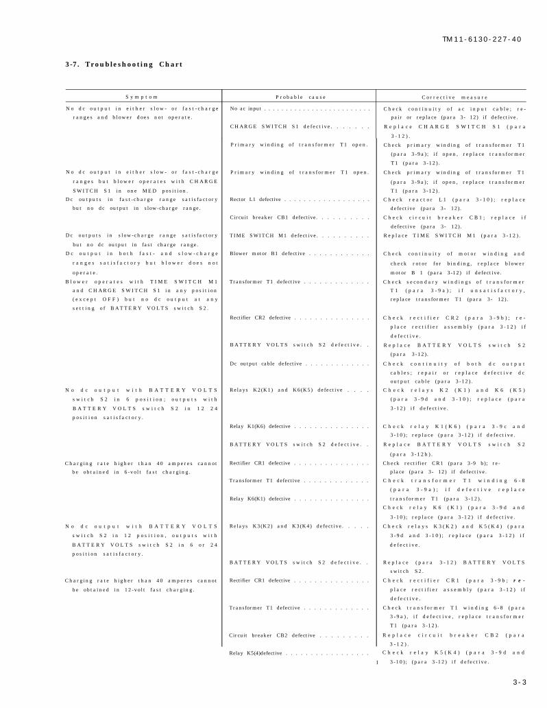
c . Troubleshoot ing C h a r t . U s e t h e t r o u b l e -
shooting chart (para 3-7 as an aid in determining
t h e p r o b a b l e c a u s e s o f t h e s y m p t o m s o f f a u l t yoperation and the corrective measures required.
d . T e s t s . U s e M u l t i m e t e r A N / U S M - 2 2 3 o rTS-352/U to perform point-to-point continuity tests
and to make voltage and resistance measurements(para 3-9 and 3-10) to determine the condition ofindiv idual parts . Refer to the schematic d iagram(fig. 2-2 and 2-3) to identify circuit components and
test point and to the wiring diagram (fig. 3-6 and3-7) for point-to-point wiring and connection points.
3 - 2
T M 1 1 - 6 1 3 0 - 2 2 7 - 4 0
3-7. Troubleshooting Chart
S y m p t o m P r o b a b l e c a u s e C o r r e c t i v e m e a s u r e
N o d c o u t p u t i n e i t h e r s l o w - o r f a s t - c h a r g e No ac input . . . . . . . . . . . . . . . . . . . . . . . . . C h e c k c o n t i n u i t y o f a c i n p u t c a b l e ; r e -
ranges and b lower does not operate . pair or replace (para 3- 12) if defective.
CHARGE SWITCH S1 defect ive . . . . . . . R e p l a c e C H A R G E S W I T C H S 1 ( p a r a
3 - 1 2 ) .
N o d c o u t p u t i n e i t h e r s l o w - o r f a s t - c h a r g e
r a n g e s b u t b l o w e r o p e r a t e s w i t h C H A R G E
SWITCH S1 in one MED pos i t ion .
Dc outputs in fast - charge range sat is factory
but no dc output in slow-charge range.
Dc outputs in s low-charge range sat is factory
but no dc output in fast charge range.
D c o u t p u t i n b o t h f a s t - a n d s l o w - c h a r g e
r a n g e s s a t i s f a c t o r y b u t b l o w e r d o e s n o t
o p e r a t e .
B l o w e r o p e r a t e s w i t h T I M E S W I T C H M 1
a n d C H A R G E S W I T C H S 1 i n a n y p o s i t i o n
( e x c e p t O F F ) b u t n o d c o u t p u t a t a n y
s e t t i n g o f B A T T E R Y V O L T S s w i t c h S 2 .
N o d c o u t p u t w i t h B A T T E R Y V O L T S
s w i t c h S 2 i n 6 p o s i t i o n ; o u t p u t s w i t h
B A T T E R Y V O L T S s w i t c h S 2 i n 1 2 2 4
p o s i t i o n s a t i s f a c t o r y .
Charging rate h igher than 40 amperes cannot
be obta ined in 6 -vo l t fast charging .
N o d c o u t p u t w i t h B A T T E R Y V O L T S
s w i t c h S 2 i n 1 2 p o s i t i o n , o u t p u t s w i t h
B A T T E R Y V O L T S s w i t c h S 2 i n 6 o r 2 4
p o s i t i o n s a t i s f a c t o r y .
Charging rate h igher than 40 amperes cannot
be obta ined in 12-vo l t fast charging .
Pr imary winding o f t rans former T1 open .
Pr imary winding o f t rans former T1 open .
Rector L1 defective . . . . . . . . . . . . . . . . . .
Circuit breaker CB1 defective. . . . . . . . . .
TIME SWITCH M1 defective. . . . . . . . . .
Blower motor B1 defective . . . . . . . . . . . .
Transformer T1 defective . . . . . . . . . . . . .
Rectifier CR2 defective . . . . . . . . . . . . . . .
B A T T E R Y V O L T S s w i t c h S 2 d e f e c t i v e . .
Dc output cable defective . . . . . . . . . . . . .
Relays K2(K1) and K6(K5) defective . . . .
Relay K1(K6) defective . . . . . . . . . . . . . . .
B A T T E R Y V O L T S s w i t c h S 2 d e f e c t i v e . .
Rectifier CR1 defective . . . . . . . . . . . . . . .
Transformer T1 defective . . . . . . . . . . . . .
Relay K6(K1) defective . . . . . . . . . . . . . . .
Relays K3(K2) and K3(K4) defective. . . . .
B A T T E R Y V O L T S s w i t c h S 2 d e f e c t i v e . .
Rectifier CR1 defective . . . . . . . . . . . . . . .
Transformer T1 defective . . . . . . . . . . . . .
Circuit breaker CB2 defective . . . . . . . . .
Check pr imary winding o f t ransformer T1
(para 3 -9a) ; i f open, replace transformer
T1 (para 3-12) .
Check pr imary winding o f t ransformer T1
(para 3 -9a) ; i f open, replace transformer
T1 (para 3-12) .
C h e c k r e a c t o r L 1 ( p a r a 3 - 1 0 ) ; r e p l a c e
defective (para 3- 12).
C h e c k c i r c u i t b r e a k e r C B 1 ; r e p l a c e i f
defective (para 3- 12).
R e p l a c e T I M E S W I T C H M 1 ( p a r a 3 - 1 2 ) .
C h e c k c o n t i n u i t y o f m o t o r w i n d i n g a n d
check rotor f or b inding , rep lace b lower
motor B 1 (para 3-12) if defective.
C h e c k s e c o n d a r y w i n d i n g s o f t r a n s f o r m e r
T 1 ( p a r a 3 - 9 a ) ; i f u n s a t i s f a c t o r y ,
replace transformer T1 (para 3- 12).
C h e c k r e c t i f i e r C R 2 ( p a r a 3 - 9 b ) ; r e -
p l a c e r e c t i f i e r a s s e m b l y ( p a r a 3 - 1 2 ) i f
d e f e c t i v e .
R e p l a c e B A T T E R Y V O L T S s w i t c h S 2
(para 3-12) .
C h e c k c o n t i n u i t y o f b o t h d c o u t p u t
c a b l e s ; r e p a i r o r r e p l a c e d e f e c t i v e d c
output cable (para 3-12) .
C h e c k r e l a y s K 2 ( K 1 ) a n d K 6 ( K 5 )
( p a r a 3 - 9 d a n d 3 - 1 0 ) ; r e p l a c e ( p a r a
3-12) i f defect ive .
C h e c k r e l a y K 1 ( K 6 ) ( p a r a 3 - 9 c a n d
3-10) ; replace (para 3 -12) i f de fect ive .
R e p l a c e B A T T E R Y V O L T S s w i t c h S 2
( p a r a 3 - 1 2 h ) .
Check rectifier CR1 (para 3-9 b); re-
place (para 3- 12) if defective.
C h e c k t r a n s f o r m e r T 1 w i n d i n g 6 - 8
( p a r a 3 - 9 a ) ; i f d e f e c t i v e r e p l a c e
transformer T1 (para 3-12) .
C h e c k r e l a y K 6 ( K 1 ) ( p a r a 3 - 9 d a n d
3-10) ; replace (para 3 -12) i f de fect ive .
C h e c k r e l a y s K 3 ( K 2 ) a n d K 5 ( K 4 ) ( p a r a
3 - 9 d a n d 3 - 1 0 ) ; r e p l a c e ( p a r a 3 - 1 2 ) i f
d e f e c t i v e .
R e p l a c e ( p a r a 3 - 1 2 ) B A T T E R Y V O L T S
switch S2.
C h e c k r e c t i f i e r C R 1 ( p a r a 3 - 9 b ; r e -
p l a c e r e c t i f i e r a s s e m b l y ( p a r a 3 - 1 2 ) i f
d e f e c t i v e .
C h e c k t r a n s f o r m e r T 1 w i n d i n g 6 - 8 ( p a r a
3 - 9 a ) , i f d e f e c t i v e , r e p l a c e t r a n s f o r m e r
T1 (para 3-12) .
R e p l a c e c i r c u i t b r e a k e r C B 2 ( p a r a
3 - 1 2 ) .
Relay K5(4)defective . . . . . . . . . . . . . . . . .
I
C h e c k r e l a y K 5 ( K 4 ) ( p a r a 3 - 9 d a n d
3-10) ; (para 3-12) i f defect ive .
3 - 3
TM 11-6130-227-40
S y m p t o m
N o d c o u t p u t w i t h B A T T E R Y V O L T S
s w i t c h S 2 i n 2 4 p o s i t i o n ; o u t p u t w i t h
B A T T E R Y V O L T S s w i t c h S 2 i n 6 o r 1 2
p o s i t i o n s a t i s f a c t o r y .
C h a r g i n g r a t e d o e s n o t i n c r e a s e w h e n
C H A R G E S W I T C H S 1 i s a d v a n c e d t o
M e d a n d H I G H .
B a t t e r y c h a r g e r o p e r a t i n g b u t a m m e t e r M 2
does not indicate any dc output .
B a t t e r y c h a r g e r s t o p s w h e n e v e r 4 0 - a m p e r e
c h a r g i n g r a t e i s e x c e e d e d d u r i n g 6 - o r
1 2 - v o l t c h a r g i n g .
T I M E S W I T C H M 1 d o e s n o t r e t u r n t o
S L O W C H A R G E p o s i t i o n
Charging rate does not drop into s low-charge
r a n g e w h e r e T I M E S W I T C H M 1 r e t u r n s
t o S L O W C H A R G E p o s i t i o n .
M a x i m u m c h a r g i n g r a t e i n f a s t - c h a r g e
range cannot be obtained.
P r o b a b l e c a u s e
Relay K4(K3) defective . . . . . . . . . . . . . . .
B A T T E R Y V O L T S s w i t c h S 2 d e f e c t i v e . .
CHARGE SWITCH S1 defect ive . . . . . . .
Ammeter M2 d isconnected or de fect ive . .
Circuit breaker CB2 or CB3 defective. . . .
C l o c k o f T I M E S W I T C H M 1
d e f e c t i v e
TIME SWITCH M1 defective. . . . . . . . . .
Reactor L1 defective . . . . . . . . . . . . . . . . .
Rect i f iers CR1 and CR2 aged for defect ive
C o r r e c t i v e m e a s u r e
C h e c k R e l a y K 4 ( K 3 ) ( p a r a 3 - 9 d a n d
3-10); (para 3- 12) if defective.
R e p l a c e B A T T E R Y V O L T S s w i t c h S 2
(para 3-12) .
R e p l a c e C H A R G E S W I T C H S 1 ( p a r a
3 - 1 2 ) .
C h e c k c o n n e c t i o n s o f a m m e t e r M 2 t o
shunt res istor R1; replace ammeter M2
(para 3-12) i f defect ive .
Check c ircui t breakers CB2 and CB3; re -
p l a c e d e f e c t i v e c i r c u i t b r e a k e r ( p a r a
3 - 1 2 ) .
Replace TIME SWITCH M1 (para 3- 12) .
R e p l a c e T I M E S W I T C H M l ( p a r a 3 - 1 2 ) .
C h e c k r e a c t o r L 1 ( p a r a 3 - 1 0 ) ; r e p l a c e
(para 3-12) i f defect ive .
C h e c k r e c t i f i e r s C R 1 a n d C R 2 ( p a r a
3 - 9 b ) ; r e p l a c e r e c t i f i e r a s s e m b l y ( p a r a
3-12) i f unsat is factory .
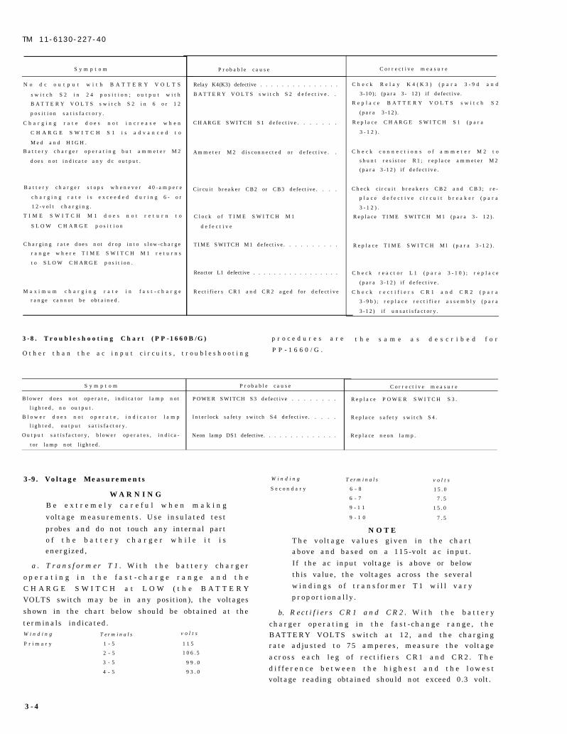
3 -8 . Troubleshoot ing Chart (PP-1660B /G) p r o c e d u r e s a r e
O t h e r t h a n t h e a c i n p u t c i r c u i t s , t r o u b l e s h o o t i n g P P - 1 6 6 0 / G .
t h e s a m e a s d e s c r i b e d f o r
S y m p t o m P r o b a b l e c a u s e C o r r e c t i v e m e a s u r e
Blower does not operate , indicator lamp not POWER SWITCH S3 defective . . . . . . . . R e p l a c e P O W E R S W I T C H S 3 .
l ighted , no output .
B l o w e r d o e s n o t o p e r a t e , i n d i c a t o r l a m p Interlock safety switch S4 defective. . . . . Replace safety switch S4.
l ighted , output sat is factory .
Output sat is factory , b lower operates , indica - Neon lamp DS1 defective. . . . . . . . . . . . . . Replace neon lamp.
tor lamp not lighted.
3-9. Voltage Measurements
W A R N I N GB e e x t r e m e l y c a r e f u l w h e n m a k i n g
voltage measurements. Use insulated test
probes and do not touch any internal parto f t h e b a t t e r y c h a r g e r w h i l e i t i senergized,
a . T r a n s f o r m e r T 1 . W i t h t h e b a t t e r y c h a r g e r
o p e r a t i n g i n t h e f a s t - c h a r g e r a n g e a n d t h eC H A R G E S W I T C H a t L O W ( t h e B A T T E R YVOLTS switch may be in any position), the voltages
shown in the chart below should be obtained at the
terminals indicated.W i n d i n g T e r m i n a l s v o l t s
P r i m a r y 1 - 5 1 1 5
2 - 5 1 0 6 . 5
3 - 5 9 9 . 0
4 - 5 9 3 . 0
W i n d i n g T e r m i n a l s v o l t s
S e c o n d a r y 6 - 8 1 5 . 0
6 - 7 7 . 5
9 - 1 1 1 5 . 0
9 - 1 0 7 . 5
N O T EThe vol tage values g iven in the chartabove and based on a 115-volt ac input.
If the ac input voltage is above or belowthis value, the voltages across the several
b.
w i n d i n g s o f t r a n s f o r m e r T 1 w i l l v a r yproport ional ly .
R e c t i f i e r s C R 1 a n d C R 2 . W i t h t h e b a t t e r y
charger operat ing in the fast -change range , theBATTERY VOLTS switch at 12, and the chargingrate adjusted to 75 amperes, measure the voltage
across each leg o f rect i f iers CR1 and CR2. Thed i f f e r e n c e b e t w e e n t h e h i g h e s t a n d t h e l o w e s tvoltage reading obtained should not exceed 0.3 volt.
3 - 4
TM 11-6130-227-40
c . Relay K1(K6) . R e l a y K 1 ( K 6 ) s h o u l d o p e r a t e equipment deenergized and with the part d iscon-when 16 to 18 volts is applied to its coil (across netted from the remainder of the circuit. The ap-
terminals 1-2) and should release when the voltage proximate resistances of the winding of reactor L1
is reduced to approximately 13 volts. and of the coils of relays K1 through K6 are given ind . R e l a y s K 2 - K 6 ( L 1 - K 5 ) . R e l a y K 2 - K 6 ( K 1 - K 5 ) the chart below.
each should operate when a vo l tage o f 4 .8 vo l ts I t e m T e r m i n a l s R e s i s t a n c e ( o h m s )
(maximum) is applied to its coil (across terminals R e a c t o r L 1 1 - 2 0 . 4 1 2
1-2) . R e l a y K 1 ( K 6 ) 1 - 2 4 0 0
Relays K2 through K6 1 - 2 8 . 0
3-10. Resistance Measurements ( K 1 t h r o u g h K 5 )
M a k e a l l r e s i s t a n c e m e a s u r e m e n t s w i t h t h e
S e c t i o n I V . R E M O V A L A N D R E P L A C E M E N T O F P A R T S A N D
T E S T I N G A F T E R R E P A I R
N O T E
A l l m a i n t e n a n c e p a r t s f o r C h a r t e r
B a t t e r y P P - 1 6 6 0 ( ) / G ( T M1 1 - 6 1 3 0 - 2 2 7 - 4 0 P ) a r e r e p l a c e a b l e a tgeneral support.
3-11. General Procedures
All parts of the PP-1660( )/G, except transformerT1, are readily accessible when the cover of the caseis removed and can be removed and replaced in -
dividually without first removing any other parts.Instructions for the removal and replacement of allfunct ional parts are provided in paragraph 3-12 .When removing parts or repairing wiring, tag leads
and mark terminals for pos i t ive indicat ion beforedisconnecting any wiring to assure correct recon-nect ion. When wir ing is replaced, use wire thatconforms with that specified in figure 3-6.
3-12. Removal and Replacement of Parts
N O T EM o s t p a r t s c a n b e r e i n s t a l l e d b y
r e m o u n t i n g t h e m i n t h e i r o r i g i n a llocations with the original hardware andr e c o n n e c t i n g t h e l e a d s . R e p l a c e m e n tinstructions are given only when special
procedures or precautions are required.
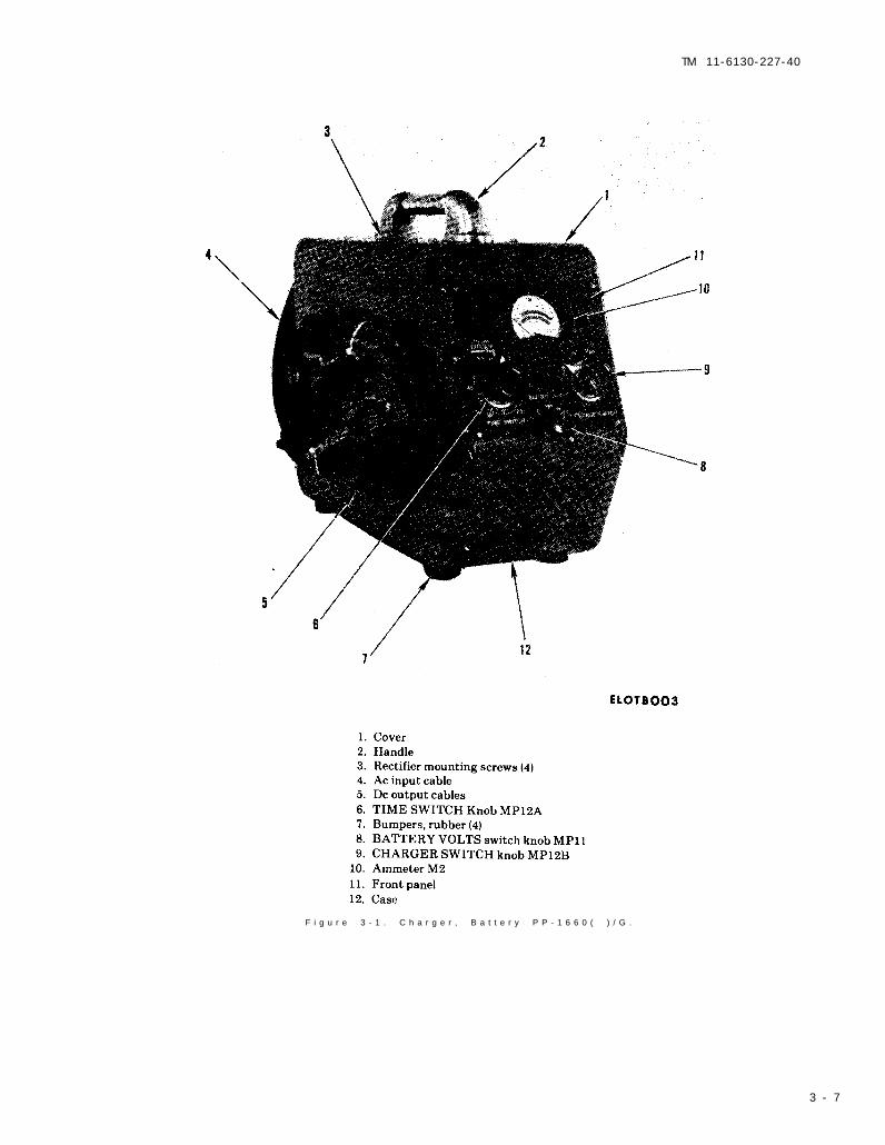
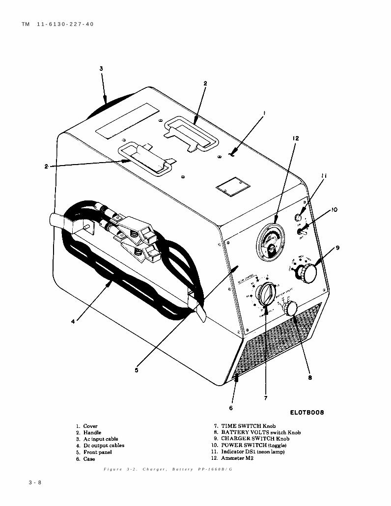
a. Cover (1, fig. 3-1). Remove four screws from thetop and three screws from each side of the cover andcarefully lift off the cover.
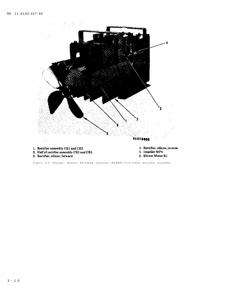
b. Blower Assembly (5 a n d 6, fig. 3-4). R e m o v ethe two hexagonal nuts that fasten blower motor B1(6) to the bracket. Disconnect the leads at blowerm o t o r B 1 a n d l i f t o u t t h e b l o w e r a s s e m b l y . T o
remove impeller MP4 (5, fig. 3-4) loosen the set-
screw in the hub and pull impeller MP4 off the shaftof the motor B1.
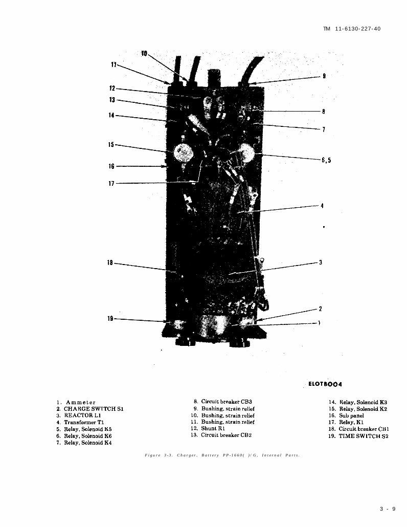
c. Ac Input Cable (4, fig. 3 – 1 ) . D i s c o n n e c t o n ecable lead from TIME SWITCH M1 (19, f ig . 3-3)
and unsolder and disconnect the other cable leadfrom the solder connection (fig. 3-6). Release the
strain relief bushing (9, fig. 3-3) in the back of the
case (12, fig. 3-1) and pull out the ac input cable.
When reinstalling the ac input cable, connect thecable lead with a lug to TIME SWITCH M1 (19, fig.3-3). Splice the other cable lead to one lead of blowermotor B1 (6 fig. 3-4) and the black lead from theprimary winding o f transformer T1 (4 , f ig . 3 -3 ) .Solder the connector and tape securely.
d. Dc Output Cables (5, fig. 3-1). The positive (redconnector) dc output cable is connected to resistor
R1 (12, fig. 3-3) and the negative (black connector)dc output cable is connectd to circuit breaker CB2(13 , f ig . 3 -3 ) . To remove e i ther dc output cable ,disconnect it, release the strain relief bushing (10 or
11, fig. 3-3) in the back of the case (12, fig. 3-1), andpull out the cable.
e. Ammeter M2 (1, fig. 3-3). Disconnect the leads,remove the mounting screws and nuts, and carefully
remove ammeter M2 from the front panel from the
front . When reconnect ing the ammeter leads , besure to observe correct polarity (fig. 3-6).
f. TIME SWITCH M1 (19, fig. 3-3). Loosen the
t w o s e t s c r e w s t h a t s e c u r e T I M E S W I T C H k n o bMP12A (6, fig. 3-1) and pull the knob off the shaft.
D i s c o n n e c t t h e l e a d s , r e m o v e t h e l o c k n u t , a n dremove TIME SWITCH M1 from the f ront panelfrom the rear . When re instal l ing TIME SWITCH
M1, rotate the shaft fu l ly counterc lockwise andinstall TIME SWITCH knob MP12A (6, fig. 3-1) sothat the pointer is at SLOW CHARGE. Be sure totighten both setscrews.
g. CHARGE SWITCH S1 (2, fig. 3-3). Loosen thet w o s e t s c r e w s t h a t s e c u r e C H A R G E S W I T C Hknob MP12B (9, fig. 3-1) and pull the knob off theshaft. Disconnect the leads, remove the locknut, and
remove CHARGE SWITCH S1 from the front panel
f r o m t h e r e a r . W h e n r e i n s t a l l i n g C H A R G E
3-5
TM 11-6130-227-40
S W I T C H S 1 , r o t a t e t h e s h a f t f u l l y c o u n -terclockwise and reinstall CHARGE SWITCH knob
MP12B (9) so that the pointer is at OFF. Be sure to
tighten both setscrews.h. BATTERY VOLTS SWITCH S2 (7 , f ig . 3 -1 ) .
Pull BATTERY VOLTS switch knob MP11 (8, fig.
3-1) straight forward off the shaft. Disconnect the
leads, remove the locknut, and remove BATTERYVOLTS switch S2 from the front panel f rom therear . When re instal l ing BATTERY VOLTS switchS2, rotate the shaft fu l ly counterc lockwise andreinstal l BATTERY VOLTS switch knob MP11(8)
so that the engraved pointer is at 6.
i . Circui t Breaker CB1 (18 , f ig . 3 -3 ) . C i r c u i tbreaker CB1 is mounted on a bracket fastened to the
top flange of transformer T1 (4, fig. 3-3). To remove
c i r c u i t b r e a k e r C B 1 , d i s c o n n e c t t h e l e a d s a n dr e m o v e t h e n u t s , l o c k w a s h e r s , a n d s c r e w s t h a tfasten circuit breaker CB1 to its bracket.
j . Rect i f i ers CR1 and CR2. R e c t i f i e r s C R 1 a n d
CR2 (2 , f ig . 3 -4 ) are connected together and areremoved as an assembly. The rectifier assembly ismounted on top of transformer T1 (4, fig. 3-3). To
remove the rect i f ier assembly , take out the four
s c r e w s t h a t s e c u r e i t t o t r a n s f o r m e r T 1 ( 4 ) ,disconnect all leads, and lift the rectifier assemblyout of the case. The four screws (3, fig. 3-1) alsomust be removed prior to removal of the rectifierassembly.
k. Reactor L1 (3, fig. 3-3). Reactor L1 is mountedin front of transformer T1 (4, fig. 3-3). To remove
reactor L1, disconnect the two pigtail leads fromT I M E S W I T C H M 1 ( 1 9 , f i g . 3 - 3 ) a n d c i r c u i t
breaker CB1 (18, fig. 3-3), remove the two mountingscrews, accessible from the bottom of the case, andlift out reactor L1.
1. Transformer T1 (4, fig. 3-3). Remove rec t i f i ersCR1 and CR2 (j above) and circuit breaker CB1 ( i
above) ; i t i s not necessary to d isconnect c ircuitbreaker CB1. Disconnect the 11 p igta i l leads o ftransformer T1, remove the four mounting screws,
a n d l i f t t r a n s f o r m e r T 1 o u t o f t h e c a s e . W h e nreinstalling transformer T1, be sure to solder andtape the connection to the ac input cable lead andthe blower motor lead (fig. 3-6) securely.
m. Subpanel (16 , f ig . 3 -3) . T h e s u b p a n e l i s aU - s h a p e d , s h e e t - m e t a l c h a s s i s o n w h i c h a r em o u n t e d r e l a y K 1 ( K 6 ) ( 1 7 , f i g . 3 - 3 ) r e l a y sK2-K6(K1-K5) (5, 6, 7, 14, 15, fig. 3-3), and circuit
breakers CB2 (13, fig. 3-3) and CB3 (8, fig. 3-3). The
subpanel is located behind transformer T1 (4, fig.3-3) and is fastened to the case by three screws.Parts mounted on the subpanel can be removedi n d i v i d u a l ( w i t h o u t r e m o v i n g t h e s u b p a n e l ) b y
d i s c o n n e c t i n g t h e i r l e a d s a n d r e m o v i n g t h emounting hardware. To remove the subpanel as an
assembly, it is necessary first to disconnect all leadsconnected to parts not mounted on the subpanel.
n . R e s i s t o r R 1 ( 1 2 , f i g . 3 – 3 ) . R e s i s t o r R 1 i smounted on the inside of the back of the case bymeans of the same screw and nut that secure thelower hanger of the ac input cable to the outside of
the case . To remove res istor R1, d isconnect theleads from its terminals and remove the nut and the
screw.
3-13. Removal and Replacement of Parts
(PP-1660B/G)
N O T EM o s t p a r t s c a n b e r e i n s t a l l e d b y
r e m o u n t i n g t h e m i n t h e i r o r i g i n a llocations with the original hardware andr e c o n n e c t i n g t h e l e a d s . R e p l a c e m e n tinstructions are given only when special
procedures or precautions are required.
a . P O W E R S w i t c h S 3 . D i s c o n n e c t t h e l e a d s ,remove the locknut, and remove POWER switch S3from the front panel from the rear.
b . F A N S A F E T Y S w i t c h S 4 . D i s c o n n e c t t h eleads , remove two screws f rom front panel , andremove SAFETY switch S4 f rom the f ront panelfrom the rear.
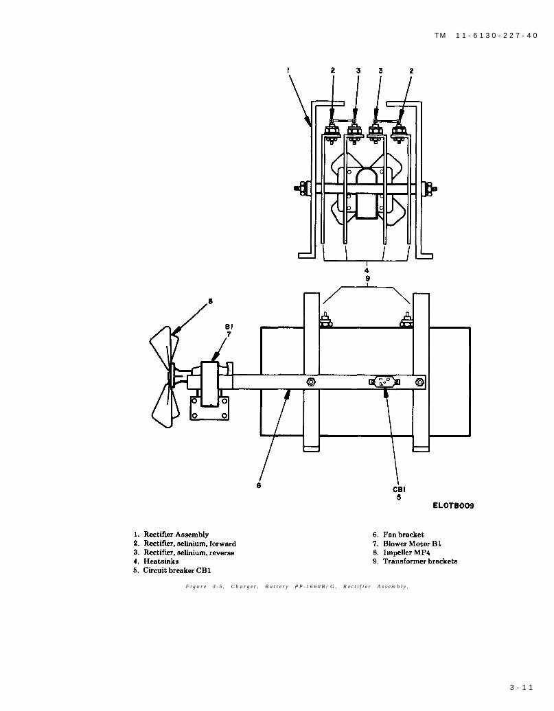
c. Circuit Breaker CB1. Circui t Breaker CB1 ismounted on a bracket fastened to the mountingbracket of the rectifier assembly. To remove circuitbreaker CB1, disconnect the leads and remove thenuts, lockwashers, and screws that fasten circuit
breaker CB1 to its bracket.d. Neon Lamp DS1. D i s c o n n e c t t h e l e a d s a n d
remove lamp assembly from front panel from the
rear, snap in, snap out.
3-14. Testing After Repair
Whenever the battery charger has been repaired,c h e c k t h e o v e r a l l , o p e r a t i o n o f t h e e q u i p m e n t .Fol low the procedure out l ined in the equipmentperformance checklist (TM 11-6130-227-12).
3 - 6
TM 11-6130-227-40
F i g u r e 3 - 1 . C h a r g e r , B a t t e r y P P - 1 6 6 0 ( ) / G .
3 - 7
T M 1 1 - 6 1 3 0 - 2 2 7 - 4 0
F i g u r e 3 - 2 . C h a r g e r , B a t t e r y P P - 1 6 6 0 B / G
3 - 8
TM 11-6130-227-40
F i g u r e 3 - 3 . C h a r g e r , B a t t e r y P P - 1 6 6 0 ( ) / G , I n t e r n a l P a r t s .
3 - 9
T M 1 1 - 6 1 3 0 - 2 2 7 - 4 0
F i g u r e 3 - 4 , C h a r g e r , B a t t e r y P P - 1 6 6 0 A ( C o n t r a c t D A A B 0 7 - 7 5 - C - 1 3 5 5 ) , R e c t i f i e r A s s e m b l y .
3 - 1 0
T M 1 1 - 6 1 3 0 - 2 2 7 - 4 0
F i g u r e 3 - 5 . C h a r g e r , B a t t e r y P P - 1 6 6 0 B / G , R e c t i f i e r A s s e m b l y .
3 - 1 1
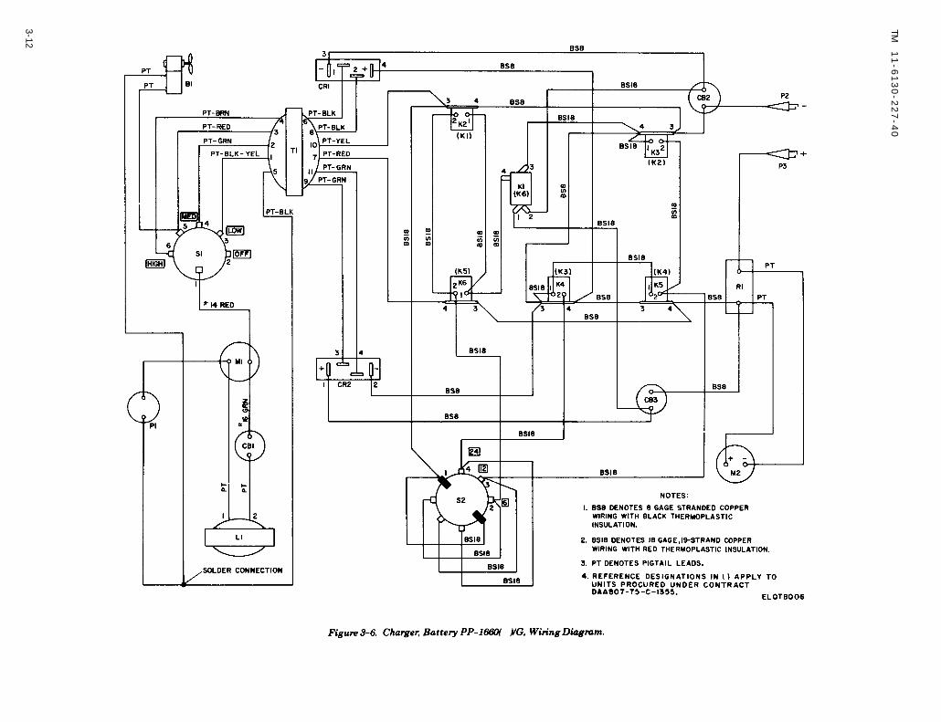
Figure 3-6.
Figure 3-6
TM
11
-61
30
-22
7-4
0
3-12
TM 11-6130-227-40
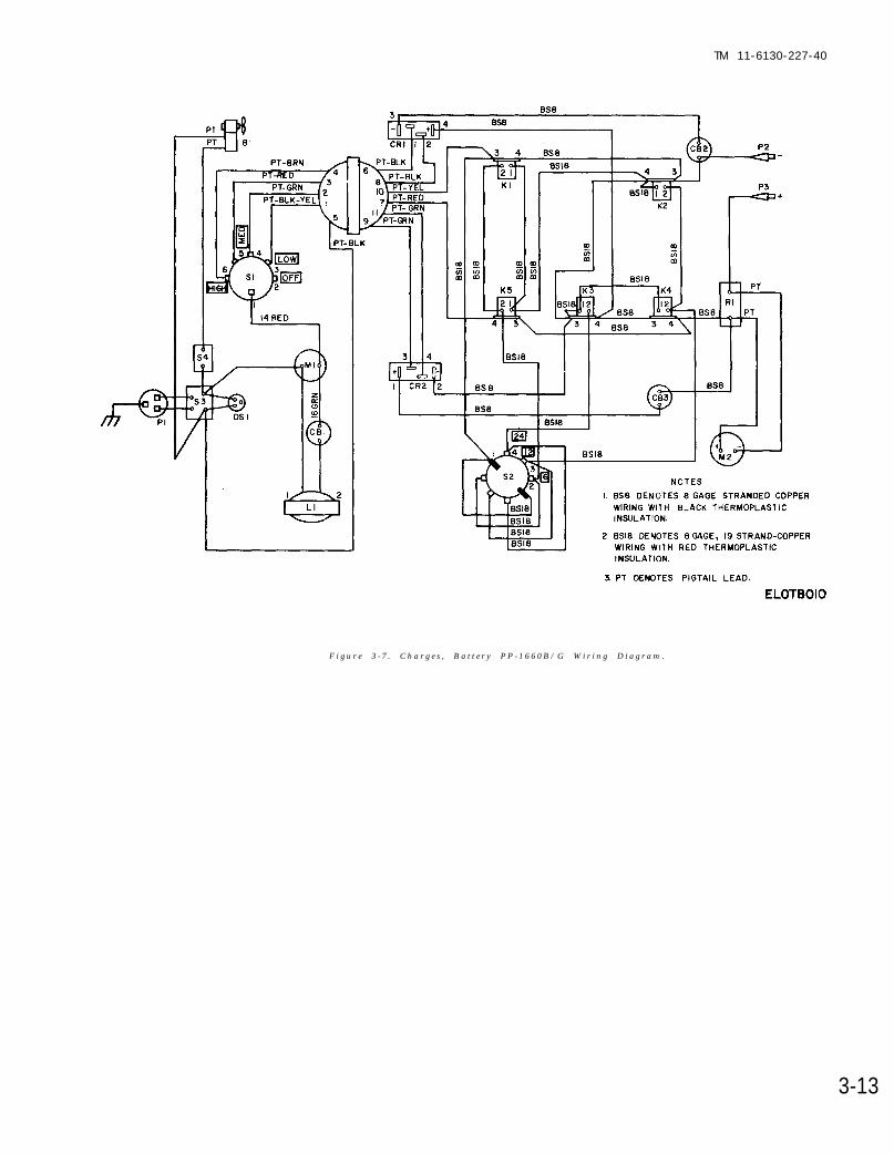
F i g u r e 3 - 7 . C h a r g e s , B a t t e r y P P - 1 6 6 0 B / G W i r i n g D i a g r a m .
3-13
TM 11-6130-227-40
A P P E N D I X A
R E F E R E N C E S
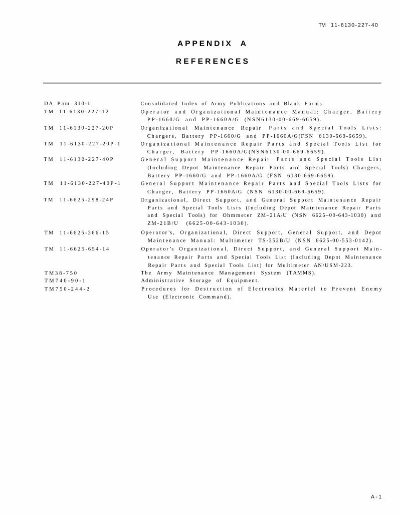
DA Pam 310-1
T M 1 1 - 6 1 3 0 - 2 2 7 - 1 2
T M 1 1 - 6 1 3 0 - 2 2 7 - 2 0 P
T M 1 1 - 6 1 3 0 - 2 2 7 - 2 0 P - 1
T M 1 1 - 6 1 3 0 - 2 2 7 - 4 0 P
T M 1 1 - 6 1 3 0 - 2 2 7 - 4 0 P - 1
T M 1 1 - 6 6 2 5 - 2 9 8 - 2 4 P
T M 1 1 - 6 6 2 5 - 3 6 6 - 1 5
T M 1 1 - 6 6 2 5 - 6 5 4 - 1 4
T M 3 8 - 7 5 0T M 7 4 0 - 9 0 - 1
T M 7 5 0 - 2 4 4 - 2
Consolidated Index of Army Publications and Blank Forms.
O p e r a t o r a n d O r g a n i z a t i o n a l M a i n t e n a n c e M a n u a l : C h a r g e r , B a t t e r yP P - 1 6 6 0 / G a n d P P - 1 6 6 0 A / G ( N S N 6 1 3 0 - 0 0 - 6 6 9 - 6 6 5 9 ) .
O r g a n i z a t i o n a l M a i n t e n a n c e R e p a i r P a r t s a n d S p e c i a l T o o l s L i s t s :
Chargers , Battery PP-1660/G and PP-1660A/G(FSN 6130-669-6659) .O r g a n i z a t i o n a l M a i n t e n a n c e R e p a i r P a r t s a n d S p e c i a l T o o l s L i s t f o r
C h a r g e r , B a t t e r y P P - 1 6 6 0 A / G ( N S N 6 1 3 0 - 0 0 - 6 6 9 - 6 6 5 9 ) .G e n e r a l S u p p o r t M a i n t e n a n c e R e p a i r P a r t s a n d S p e c i a l T o o l s L i s t
(Including Depot Maintenance Repair Parts and Special Tools) Chargers,Battery PP-1660/G and PP-1660A/G (FSN 6130-669-6659) .
G e n e r a l S u p p o r t M a i n t e n a n c e R e p a i r P a r t s a n d S p e c i a l T o o l s L i s t s f o r
Charger , Battery PP-1660A/G (NSN 6130-00-669-6659) .
Organizat ional , Direct Support , and General Support Maintenance RepairParts and Special Tools Lists (Including Depot Maintenance Repair Partsand Special Tools) for Ohmmeter ZM–21A/U (NSN 6625–00-643-1030) andZ M - 2 1 B / U ( 6 6 2 5 - 0 0 - 6 4 3 - 1 0 3 0 ) .
Operator ’ s , Organizat ional , Direct Support , General Support , and DepotMaintenance Manual : Mult imeter TS-352B/U (NSN 6625-00-553-0142) .
O p e r a t o r ’ s O r g a n i z a t i o n a l , D i r e c t S u p p o r t , a n d G e n e r a l S u p p o r t M a i n -
tenance Repair Parts and Special Tools List (Including Depot Maintenance
Repair Parts and Special Tools List) for Multimeter AN/USM-223.The Army Maintenance Management System (TAMMS).Administrative Storage of Equipment.
P r o c e d u r e s f o r D e s t r u c t i o n o f E l e c t r o n i c s M a t e r i e l t o P r e v e n t E n e m yUse (Electronic Command).
A - 1

T M 1 1 - 6 1 3 0 - 2 2 7 - 4 0
By Order of the Secretary of the Army:
Official:R O B E R T M . J O Y C E
Major General, United States Army
The Adjutant General
Distr ibut ion:
To be distributed in accordance with Special Mailing List.
E . C . M E Y E RGeneral, United States Army
Chief of Staff
U. S . GOVERNMENT PRINTING OFFICE : 1989 0- 242-451 (5286)

PIN : 012152-000