TM 10-3930-256-35 DIRECT AND GENERAL SUPPORT AND …
80
TM 10-3930-256-35 DEPARTMENT OF THE ARMY TECHNICAL MANUAL DIRECT AND GENERAL SUPPORT AND DEPOT MAINTENANCE MANUAL TRUCK, LIFT, FORK, ELECTRIC SOLID RUBBER TIRES 6000 POUND CAPACITY ARMY MODEL MHE-198 BAKER MODEL FTD-060-EE FSN 3930-724-4057, 130 IN. LIFT FSN 3930-724-4059, 172 IN. LIFT HEADQUARTERS, DEPARTMENT OF THE ARMY TAGO 8176A APRIL 1965
Transcript of TM 10-3930-256-35 DIRECT AND GENERAL SUPPORT AND …

TM 10-3930-256-35
DEPARTMENT OF THE ARMY TECHNICAL MANUAL
DIRECT AND GENERAL SUPPORT ANDDEPOT MAINTENANCE MANUAL
TRUCK, LIFT, FORK, ELECTRICSOLID RUBBER TIRES
6000 POUND CAPACITYARMY MODEL MHE-198
BAKER MODEL FTD-060-EEFSN 3930-724-4057, 130 IN. LIFTFSN 3930-724-4059, 172 IN. LIFT
HEADQUARTERS, DEPARTMENT OF THE ARMY
TAGO 8176A
APRIL 1965

TM 10-3930-256-35
SAFETY PRECAUTIONS
OPERATIONRefer to TM 10-3930-256-10 for safety precautions to be observed during operation of the fork lift truck.
HYDRAULIC SYSTEMBefore working on any part of the hydraulic system, be sure:
1. Lift carriage is fully lowered.2. Mast is tilted fully DOWN.3. All hydraulic pressure is relieved from unit or hose to be serviced.4. All personnel and materiel are clear, should some system be operated accidentally.5. Disconnect battery at charging receptacle, except when battery power is required to support the
maintenance being done.
ELECTRICAL SYSTEM1. Avoid contact with spilled electrolyte. It is corrosive to most metals and fabrics and can burn skin if not
washed off immediately with running water.2. Be very careful of flame, smoking, or creating sparks by short circuiting near charging or recently charged
batteries. Hydrogen gas given off during charging is explosive and easily ignited.3. Disconnect battery at charging receptacle, except when battery is needed to support maintenance being
done.4. Remove rings, metal watch bands, or any object which might short across the electrical circuit. Serious
burns can result, and equipment can be damaged, if this is not done.

TM 10-3930-256-35
TECHNICAL MANUAL HEADQUARTERSDEPARTMENT OF THE ARMY
No. 10-3930-256-35 WASHINGTON, D.C., 5 April1965
DIRECT AND GENERAL SUPPORTAND DEPOT MAINTENANCE MANUAL
TRUCK, LIFT, FORK, ELECTRIC,SOLID RUBBER-TIRED WHEELS
6,000 POUND CAPACITYBAKER MODEL TD -EE, ARMY MODEL MHE 198
CONTRACT NUMBER DSA 020628-MP302FSN 3930-724-4057 (130 INCH LIFT)FSN 3930-724-4059 (172 INCH LIFT)
Paragraph PageCHAPTER 1. INTRODUCTIONSection I. GENERAL
Scope ....................................................................................................... 1 3Appendixes............................................................................................... 2 3Maintenance forms and records............................................................... 3 3Reporting of equipment manual improvements ...................................... 4 3Orientation................................................................................................ 5 3
II. DESCRIPTION AND DATADescription ............................................................................................... 6 3Tabulated data ......................................................................................... 7 3
CHAPTER 2. MAINTENANCE INSTRUCTIONSSection I. TROUBLESHOOTING
Troubleshooting........................................................................................ 8 6II. ELECTRICAL SYSTEM
Horn button wiring .................................................................................... 9 10Wiring, head-, tail- and stop lights............................................................ 10 10
III. FRONT AXLEGeneral..................................................................................................... 11 15Power axle ends ...................................................................................... 12 15Power axle assembly, complete............................................................... 13 15Drive gear................................................................................................. 14 21Drive axle adapter (including coupling) ................................................... 15 21
IV. REAR AXLESteering axle ............................................................................................ 16 23Steering knuckles, pins and bearings ...................................................... 17 26
V. BRAKESGeneral..................................................................................................... 18 26Parking brake system............................................................................... 19 26Brake assembly........................................................................................ 20 26Brake master cylinder............................................................................... 21 26Brake pedal and linkage........................................................................... 22 27
VI. WHEELSWheels ..................................................................................................... 23 29Tires ......................................................................................................... 24 29
AGO l8175A
1

TM 10-3930-256-35
Paragraph PageSection VII. STEERING
Steering gear............................................................................................ 25 30Tie rods .................................................................................................... 26 44Bell crank.................................................................................................. 27 44Steering pump.......................................................................................... 28 44
VIII. HYDRAULIC LIFT COMPONENTSHydraulic pump ........................................................................................ 29 48Hydraulic control valve ............................................................................. 30 49Hydraulic tilt cylinders............................................................................... 31 51Lift cylinder (130 inch lift).......................................................................... 32 51Crosshead assembly (130 inch lift) ......................................................... 33 52Inner upright assembly (130 inch lift) ....................................................... 34 52Lift cylinder (172 inch lift).......................................................................... 35 54Crosshead, inner upright, and carriage assembly.................................... 36 57Hydraulic oil tank ...................................................................................... 37 57
IX. ELECTRIC MOTORSGeneral..................................................................................................... 38 60
‘ Travel motor 9 .......................................................................................... 39 62Hydraulic pump motor .............................................................................. 40 64Steering motor.......................................................................................... 41 64Electrical equipment box cover ................................................................ 42 67Relays....................................................................................................... 43 68Fuseholder assembly ............................................................................... 44 68Directional switch .................................................................................... 45 68
APPENDIX I. REFERENCES......................................................................................... 70II. MAINTENANCE ALLOCATION ............................................................... 72III. REPAIR PARTS AND SPECIAL TOOL LISTS ........................................ 73IV. DIRECT AND GENERAL SUPPORT MAINTENANCE
SUPPORT OF ORGANIZATIONAL LEVEL SERVICE ONRECEIPT OF NEW EQUIPMENT............................................................ 74
2
TM 10-3930-256-35
CHAPTER 1
INTRODUCTION
Section I. GENERAL1.ScopeThese instructions are published for the use of personnelresponsible for direct and general support and depotmaintenance of Truck, Lift, Fork, Electric, Solid RubberTired Wheels, 6,000 Pound Capacity, Baker Model FTD-060- EE, Army Model MHE 198, Federal Stock Number3930-724-4057 (130 inch lift), Federal Stock Number3930-724-4059 (172 inch lift). Instructions in this manualare applicable to trucks procured under contract numberDSA- 4-020628-MP302.
2. AppendixesAppendixes with references applicable to direct andgeneral support and depot maintenance are as follows:
a. Appendix I is a list of current references.b. Appendix II, Maintenance Allocation Chart, is
published only in TM 10-3930-256 20.c. Appendix III, Repairs Parts and Special Tool
Lists, is published under separate cover TM103930-256-35P.
d. Appendix IV contains the Direct and GeneralSupport maintenance support of Organizationallevel service on receipt of new equipment.
3. Maintenance Forms and RecordsThe maintenance forms, records, and reports
to be used in direct and general support and depotmaintenance of this truck are listed and described in TM38-750.
4. Reporting of Equipment Manual Improvementsa. The direct reporting by the individual user of
errors, omissions, and recommendations forimproving this manual is authorized andencouraged. DA Form 2028 (RecommendedChanges to DA Publications) will be used forreporting these improvements. This form will becompleted in triplicate using pencil, pen, ortypewriter. The original and one copy will beforwarded direct to Commanding General, U.S.Army Mobility Equipment Center: ATTN:SMOME-MMP, Post Office Drawer 58, St. Louis,Mo. 63166. One information copy will beprovided to the individual’s immediate su-pervisor (e.g., officer, noncommissioned officer,supervisor, etc.).
b. Report all equipment improvement recom-mendations as prescribed by TM 38-750.
5. OrientationThroughout this manual, the use of the terms right, left,front, and rear, indicates directions from the viewpoint ofthe operator sitting in the seat of the truck, unless it isobvious from the text this is not intended.
Section II. DESCRIPTION AND DATA
6. DescriptionRefer to TM 10-3930-25620 for a general description ofthe truck.
7. Tabulated DataRefer also to TM 10-3930-25610 and TM 10-3930-25620for tabulated data related to the organizationalmaintenance level.
3

TM 10-3930-256-35a. Electrical System (fig. 1).
(1) Battery type GFE (Government Furnished Equipment), either lead-acid ornickel-iron, alkaline electrolyte. 36 volt, dc, two-wire, battery,spark enclosed.
(2) Motors Steer motor, pump motor, travel motor.(a) Type Series wound, relay energized.(b) Overload protection Thermal relays (on motor housings)
Fuses (in control circuit)Fusetrons (in motor lines)
(c) Steer motor Controlled by seat actuated switch. Constant run when oper-ator is seated. Loaded only when steer effort is required.Constant speed.
(d) Pump motor Controlled by lift and tilt valve actuated switch. Runs onlyas needed. Constant speed.
(e) Travel motor Reversible. Four speeds available. Reversing by reversingfield current polarity. Speed and power control by selectionof resistances in motor circuit.
(f) Travel motor controls1. Direction Directional control switch on steering column. Forward-Off-
Reverse.2. Speed Accelerator master assembly. Three micro switches energize
control relays in sequence. Time delay acceleration andplugging control incorporated.
b. Hydraulic Systems.
(1) System pressure (lift) 1800 psi relief valve setting(2) Hoist speed empty (both 36 fpm
lift heights(3) Hoist speed loaded 22 fpm(4) Main pump
(a) Type Gear(b) Capacity (rated) 6.4 gpm at 1000 psi and 1200 rpm(c) Actuation Switch at lift and tilt control
(5) Steer pump(a) Type Vane(b) Capacity 1.5 gpm at 1000 psi and 1200 gpm(c) Actuation By truck seat occupancy (micro switch). Constant run.
(6) Power steering Saginaw(a) Type Rotary valve(b) Hydraulic system type Open center. Pressure only on demand.
4

TM 10-3930-256-35
Figure 1. Schematic wiring diagram.AGO 8176A
5

TM 10-3930-256-35
CHAPTER 2
MAINTENANCE INSTRUCTIONS
Section I. TROUBLESHOOTING
8. Troubleshooting
This paragraph contains, in tabular form, guidance in locating causes of trouble. Some mal- functions of equipment willgive more than one symptom. For this reason, determine from the operator when possible all complaints on truckperformance. Compare these complaints with all "Trouble" entries in the chart, to find a common cause for the complaints.This procedure will usually save time and effort. A troubleshooting chart, with remedies limited to organizationalmaintenance capabilities, is included in TM 10-3930-256-20. A separate troubleshooting chart for power steering situationsis at the end of the paragraph covering service of the steering gear (par. 25).
a. Electrical.(1) Truck will not start or develop full power.
Probable cause RemedyDead battery ..................................................................... Replace or charge (TM 10-3930-256-10).Fusetron blown.................................................................. Replace (TM 10-3930-256-20).Defective battery plug or receptacle.................................. Replace plug or receptacle (TM 10-3930-256-20).Braided shunt in relay broken ........................................... Replace shunt.Contacts dirty, worn or broken in relay or directional ........ Clean contact tips: replace if necessary (TM 10-3930-switch. 256-20).Dirt in relay causing mechanical binding .......................... Clean contactor thoroughly (TM 10-3930-256-20).Mechanical binding in contractor or accelerating .............. Adjust or replace defective parts (TM 10-3930-256-20).
switch.Pole faces of plugging relay magnet not sealing prop- ..... Clean, adjust or replace (TM 10-3930-256-20).
erly.Snap switches malfunctioning in accelerator switch ........ Replace and adjust as necessary (TM 10-3930-256-20).Seat switch not working .................................................... Adjust or replace switch (TM 10-3930-256-20).Open circuit due to loose connections in master switches. Clean and secure connections firmly (TM 10-3930-256-20).
(2) All speeds not obtainable.
Probable cause RemedyOpen in relay main circuit ................................................. Locate and eliminate.Pole faces of plugging relay magnet not making good...... Clean, adjust, or replace defective parts (TM 10-3930-contact. 25620).Object lodged in relay contact .......................................... Remove .object.Dirty contacts .................................................................... Clean or replace contacts (TM 103930-256-20).Snap switches in accelerating master malfunctioning....... Replace snap switches on roller arm and yoke as neces-
sary (TM 10-3930-256-20).Sticking or binding of accelerator in any part of stroke ..... Correct binding of the accelerator.
(3) Overheating.Probable cause Remedy
Dirty contacts .................................................................... Clean contactsBroken, worn or improperly adjusted brushes or brush..... Adjust or replace brushes or brush holders (para. 37).holders in travel motor.Vehicle operating in low speed for prolonged periods ...... Check operation.
AGO 8176A6

TM 10-3930-256-35
(4) Improper plugging control and timing through all speeds.Probable cause Remedy
Sticking of the accelerator stroke in master switch ........... Correct binding.Improper timing through all speeds ................................... Adjust timing (TM 10-3930-2520).Shorted wires..................................................................... Locate and eliminate short.Open relay contact in main circuit ..................................... Locate and correct.Dirt in relay or directional switch........................................ Clean unit thoroughly (TM 10-3930-256-20).Dirty contacts in contractor or directional switch ............... Clean contacts, or replace (TM 10-3930-25620).
b. Brakes.(1) Brakes dragging.
Probable cause RemedyMaster cylinder compensating port plugged...................... Overhaul master cylinder (para. 21).Seat brake improperly adjusted......................................... adjust so that brake does not drag when seat is down,
and is firmly applied when seat is up (TM 10-3930-256-20).Mineral oil in brake system................................................ Drain and flush system, replace all cups, and service as
required (paras. 20 and 21).Improper service brake adjustment ................................... Adjust brakes (TM 10-3930-25620).
(2) Brake pedal goes to floor.Probable cause Remedy
Worn lining ....................................................................... Adjust lining clearance (TM 10-3930-256-20), or installnew lining (para. 20).
Air in system...................................................................... Bleed system (TM 10-3930-256-20).Improper brake adjustment .............................................. Adjust brake shoes (TM 10-3930-25-20).Fluid low in master cylinder .............................................. Replenish fluid and check for leaks (LO 10-3930-256-20).Pedal improperly adjusted ................................................Adjust linkage (para. 22).
(3) Brake pedal under pressure gradually goes to floor plate.Probable cause Remedy
Leaks in hydraulic brake system ...................................... Locate and eliminate leaks.Scored master cylinder bore .. .......................................... .Install new master cylinder (TM 10-3930-256-20).
(4) Brake pedal has springy or rubbery action.Probable cause Remedy
Air in system .....................................................................- Bleed system (TM 10-3930-256-20).Improper brake adjustment .. ............................................ Adjust brakes shoes (TM 10-3930-256-20).
(5) Weak braking action.Probable cause Remedy
Improperly adjusted brakes .............................................. Adjust brakes shoes (TM 10-3930-256-20).Oil on linings...................................................................... Replace lining (para. 20).Incorrect lining ................................................................... Replace lining (para. 20).
(6) Heavy braking action.Probable cause Remedy
Brake lining grease soaked .............................................. Replace lining (para. 20).Brake shoes improperly adjusted ..................................... Adjust brake shoes (TM 10-3930-256-20).Brake backing plate loose ................................................ Tighten or replace (TM 10-3930-256-20).
(7) Brake releases slowly.Probable cause Remedy
Hydraulic fluid congealed .................................................. Drain, flush and replace with proper brake fluid (LO10-3930-256-20).
Retraction of brake shoes restricted by weak return ......... Clean, adjust or replace as necessary (para. 20).springs, or dirt.
(8) Truck pulls to one side.Probable cause Remedy
Improperly set brake shoes .............................................. Adjust brake shoes (TM 10-3930-256-20).Brake linings grease soaked . ........................................... Replace brake linings (para. 20).
AGO 1876A
7

TM 10-3930-256-35c. Steering. Refer to paragraph 25 for steering gear troubleshooting.d. Hydraulic.(1) Lift carriage will not lift load.
Probable cause RemedyOil leaks In hoses .............................................................. Inspect fittings and couplings, tighten or replace as
required (TM 10-3930-256-20).Defective pump ................................................................ Replace pump (TM 10-3930-256-20).Fusetron blown . ................................................................ Replace (TM 10-3930-256-20),Defective valve ................................................................. Inspect plunger operation. Check pressure.(2) Load creeps down from raised position.
Probable cause RemedyOil leak in lines ................................................................. Tighten fittings and couplings (TM 10-3930-256-20).Leaky control valve ........................................................... Tighten connections, replace valve if necessary (TM 10-
3930-25620).(3) Hoisting speed erratic.
Probable cause RemedyAir in system ..................................................................... Bleed air from system (para. 32).Low level in reservoir......................................................... Fill reservoir to prescribed level (LO 10-3930-256-20).(4) Control valve plungers will not return to neutral.
Probable cause RemedySticking plungers ............................................................... Apply oil OE sparingly to plungers.Broken springs or dirt lodged in seats ............................... Replace or clean as necessary (para. 32).(5) Forks uneven when load is lifted.
Probable cause RemedyLift chains out of adjustment.............................................. Adjust as necessary (TM 10-3930-256-20).(6) No motion of hydraulic unit when first started up.
Probable cause RemedyOil supply in tank too low................................................... Fill (LO 10-3930-256-20).Oil viscosity too heavy....................................................... See lubrication chart (LO 10-3930-256-20).Air leak in pump inlet line................................................... Tighten hose (TM 10-3930-25620).Restricted pump inlet line .................................................. Repair or replace (TM 10-3930-256-20).Broken pump drive shaft, motor shaft or coupling............. Repair or replace.Pump completely worn out ................................................ Replace pump (TM 10-3930-256-20).Weak or broken relief valve spring .................................... Replace spring (para. 30).Relief valve plunger stuck by dirt or foreign matter ........... Clean or replace (para. 30).Pump rotating in wrong direction....................................... Check motor internal connections (para. 38).Insufficient pressure to start load ...................................... Check pressure.Machine overloaded .......................................................... Reduce load.Failure at control valve switch ........................................... Replace (TM 10-3930-256-20).(7) Loss of motion during operation.
Probable cause RemedyLoss of oil supply due to broken pump inlet, outlet ........... Replace line (TM 10-3930-256-20).
or cylinder connecting lines or tank return line.(8) Slow motion.
Probable cause RemedyPump wearing out.............................................................. Replace (TM 10-3930-256-20).Pump rpm too slow............................................................ Check pump motor, battery (para. 38, or TM 10-3930-256-10).Failure in hydraulic lines.................................................... Replace lines (TM 10-3930-256-20).Relief valve plunger held partially off its seat by dirt.......... Clean or replace (para. 30).or foreign matter.Badly scored relief valve plunger or seat........................... Replace valve (para. 30).Weak relief valve spring .................................................... Replace (para. 30).Aerated oil supply (foam in tank)....................................... Change oil.Oil too thin ....................................................................... Check lube chart for proper grade (LO 10-3930-256-20).
AGO 8176A8
TM 10-3930-256-35
Probable cause RemedyOil supply too low............................................................... Fill reservoir.Worn or scored piston packing.......................................... Look for dirt or chips in oil. Replace packing (para. 32).ID of cylinder tube badly scored or nicked......................... Replace cylinder (para. 32).Cylinder misalignment ....................................................... Correct (TM 10-3930-256-20).Linkage to valve plunger bent or out of adjustment,.......... Adjust.thereby restricting length of travel of valve plungerto full open position.Mechanical obstruction of moving parts ............................ Remove obstruction.
(9) Jerky motion.Probable cause Remedy
Air in system ..................................................................... Bleed hydraulic system (para. 32e).Cylinder misaligned due to structural warpage.................. Adjust.
(10) Speed of operation slows down after usage.Probable cause Remedy
Pump worn Replace (TM 10-3930-256-20).Improper oil used in system .............................................. Check lube chart for proper grade (LO 10-3930-256-20).Dirt or foreign matter in system ......................................... Drain, flush out system, replace with new oil.
(11) Noisy operation.Probable cause Remedy
Air in hydraulic system....................................................... Bleed system (para. 32e).Insufficient oil supply ......................................................... Fill reservoir.Pump worn out .................................................................. Replace (TM 10-3930-256-20).Air leak in pump intake line ............................................... Tighten hose (TM 10-3930-256-20).Pump coupling worn.......................................................... Replace.Misalignment between motor shaft and pump drive.......... Align.shaft.Vibration of pump lines...................................................... Secure lines.Chattering relief valve. Weak relief valve spring ............... Replace.Incorrectly set relief valve pressure................................... Reset.Broken or cracked gears in pump ..................................... Replace pump (TM 10-3930-256-20).
(12) Oil heats up rapidly.Probable cause Remedy
Pump slippage. Oil too thin................................................ Check lube chart for proper grade.Continued operation at relief valve pressure setting ......... Check operating procedures and load weights.Operating pressure is close to relief valve pressure ......... Check operating procedures and load weights.setting.Operating at excessively high pressure............................. Check pressure setting.Dirty oil ....................................................................... Change oil.Misalignment between pump drive shaft and motor.......... Align.shaft.
(13) Hoist cylinder packing leaks.Probable cause Remedy
Packing worn..................................................................... Tighten gland nut, replace packing (par. 32).Piston scored..................................................................... Replace cylinder (para. 32).
(14) Hoist or tilt cylinder lowers or tilts while truck stands idle.Probable cause Remedy
Worn packing .................................................................... Replace (para. 31 or 32).Failure in hydraulic line...................................................... Check, tighten or replace (TM 10-3930-256-20).Scored cylinder walls......................................................... Replace entire cylinder (TM 10-3930-25620 or para.32).
(15) Reservoir flows over.Probable cause Remedy
Excess oil in reservoir ....................................................... Check oil level plug with forks in lowered position andtilted back.
AGO 8176A9
TM 10-3930-256-35Section II. ELECTRICAL SYSTEM
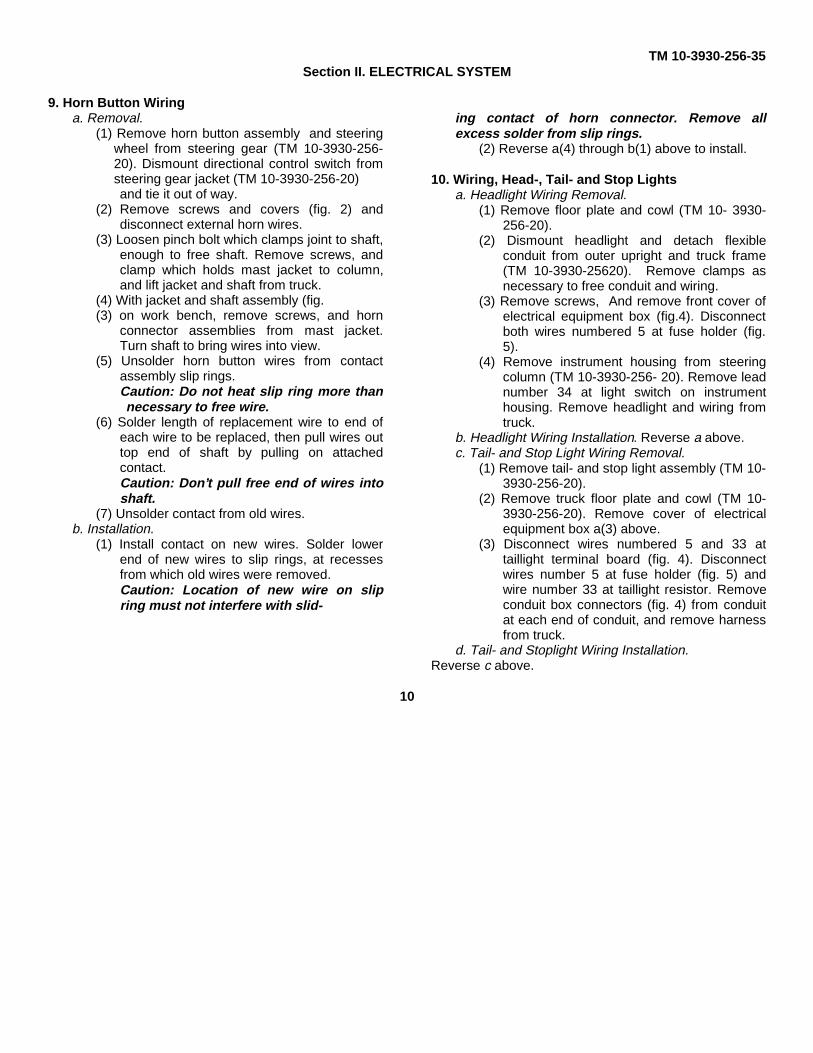
9. Horn Button Wiringa. Removal.
(1) Remove horn button assembly and steeringwheel from steering gear (TM 10-3930-256-20). Dismount directional control switch fromsteering gear jacket (TM 10-3930-256-20) and tie it out of way.
(2) Remove screws and covers (fig. 2) anddisconnect external horn wires.
(3) Loosen pinch bolt which clamps joint to shaft,enough to free shaft. Remove screws, andclamp which holds mast jacket to column,and lift jacket and shaft from truck.
(4) With jacket and shaft assembly (fig.(3) on work bench, remove screws, and horn
connector assemblies from mast jacket.Turn shaft to bring wires into view.
(5) Unsolder horn button wires from contactassembly slip rings.Caution: Do not heat slip ring more thannecessary to free wire.
(6) Solder length of replacement wire to end ofeach wire to be replaced, then pull wires outtop end of shaft by pulling on attachedcontact.Caution: Don’t pull free end of wires intoshaft.
(7) Unsolder contact from old wires.b. Installation.
(1) Install contact on new wires. Solder lowerend of new wires to slip rings, at recessesfrom which old wires were removed.Caution: Location of new wire on slipring must not interfere with slid-
ing contact of horn connector. Remove allexcess solder from slip rings.
(2) Reverse a(4) through b(1) above to install.
10. Wiring, Head-, Tail- and Stop Lightsa. Headlight Wiring Removal.
(1) Remove floor plate and cowl (TM 10- 3930-256-20).
(2) Dismount headlight and detach flexibleconduit from outer upright and truck frame(TM 10-3930-25620). Remove clamps asnecessary to free conduit and wiring.
(3) Remove screws, And remove front cover ofelectrical equipment box (fig.4). Disconnectboth wires numbered 5 at fuse holder (fig.5).
(4) Remove instrument housing from steeringcolumn (TM 10-3930-256- 20). Remove leadnumber 34 at light switch on instrumenthousing. Remove headlight and wiring fromtruck.
b. Headlight Wiring Installation. Reverse a above.c. Tail- and Stop Light Wiring Removal.
(1) Remove tail- and stop light assembly (TM 10-3930-256-20).
(2) Remove truck floor plate and cowl (TM 10-3930-256-20). Remove cover of electricalequipment box a(3) above.
(3) Disconnect wires numbered 5 and 33 attaillight terminal board (fig. 4). Disconnectwires number 5 at fuse holder (fig. 5) andwire number 33 at taillight resistor. Removeconduit box connectors (fig. 4) from conduitat each end of conduit, and remove harnessfrom truck.
d. Tail- and Stoplight Wiring Installation.Reverse c above.
10

TM 10-3930-256-35
Figure 2. Steering column removal.
11

TM 10-3930-256-35
Figure 3. Horn button wire replacement.AGO 8176A
12

TM 10-3930-256-35
Figure 4. Electrical system arrangement.AGO 8176A
13

TM 10-3930-256-35
Figure 5. Electrical equipment box.AGO 8176A
14

SECTION III. FRONT AXLE TM 10-3930-256-35
11. General
This section contains direct and general supportmaintenance instructions for the power axle, and themechanical adapter and coupling through which thetravel motor drives the axle. Because of the closemechanical and functional relationship of the axle,adapter, and coupling, service of these assemblies willbe grouped in the order in which they are encountered,in servicing the power axle, as though all were axlecomponents. Periodic overhaul of the entire axleassembly is not anticipated. Rather, service willgenerally be required either at those elements of theaxle outboard of the differential assembly, or to thedifferential assembly itself. The following instructionstreat each of these areas separately.
12. Power Axle Ends
a. Removal and Disassembly.(1) Raise vehicle to convenient working height
and remove front wheels (TM 103930-256-20).
(2) Disconnect brake lines and remove fittings(fig. 6).
(3) Drain axle lubricant (LO 10-3930-25620).(4) Remove nuts, washers and tapered bushings
holding final drive gear case (fig. 7) to axlehousing. Tap studs as necessary to separate,and remove gear case with attached parts.Axle will stay in housing. Note. The axlehousing is seldom of maintenancesignificance; if necessary to service it, refer toparagraph 13.
(5) Remove and discard gasket. Remove bolts,washers, and axle shaft bearing retainer,then pull out axle shaft and ball bearing.Take retaining collar from within axlehousing. If to be serviced, press bearingfrom axle shaft.
(6) Take cotter pin, nut and washer from end offinal drive gearshaft, and remove final drivegear, final drive gearshaft, bearing cups andcones, and rollers from gear case.
AGO 8176A
Figure 6. Power axle, front view
(7) Remove screws and nuts to wheel adapter,and separate gearshaft, adapter, oil seals andwasher. Remove wheel bolts, and removebrake drum.
b. Inspection.(1) Check oil seals for any imperfection.(2) Examine bearing rollers, cups and cones for
wear. Replace as a set, if any element isworn, ridged or pitted.
(3) Inspect final drive gear and axle shaft pinionfor chipping, cracks, or scoring.
c. Assembly and Installation. Assemble by reversingb above, noting the following:
(1) Coat wheel bearings and oil seals with GAAbefore assembly.
(2) After gear, washer, and nut have beeninstalled on final drive shaft, tighten nut untilslight drag is felt when turning case. This iswheel bearing adjustment, with correct finalresult of no endplay but slight bearing drag. Ifcotter pin will not enter hole with thisadjustment, stake nut into spline slot on shaft.After installation bleed brake hydraulic system(TM 10-3930-256-20).
13. Power Axle Assembly, Complete
a. Removal (Axle, Adapter, and Motor).(1) Remove entire mast assembly, includ-
15

TM 10-3930-256-35
Figure 7. Power end axle, exploded view.
16
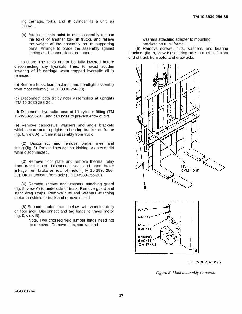
TM 10-3930-256-35ing carriage, forks, and lift cylinder as a unit, asfollows:
(a) Attach a chain hoist to mast assembly (or usethe forks of another fork lift truck), and relievethe weight of the assembly on its supportingparts. Arrange to brace the assembly againsttipping as disconnections are made.
Caution: The forks are to be fully lowered beforedisconnecting any hydraulic lines, to avoid suddenlowering of lift carriage when trapped hydraulic oil isreleased.
(b) Remove forks, load backrest, and headlight assemblyfrom mast column (TM 10-3930-256-20).
(c) Disconnect both tilt cylinder assemblies at uprights(TM 10-3930-256-20).
(d) Disconnect hydraulic hose at lift cylinder fitting (TM10-3930-256-20), and cap hose to prevent entry of dirt.
(e) Remove capscrews, washers and angle bracketswhich secure outer uprights to bearing bracket on frame(fig. 8, view A). Lift mast assembly from truck.
(2) Disconnect and remove brake lines andfittings(fig. 6). Protect lines against kinking or entry of dirtwhile disconnected.
(3) Remove floor plate and remove thermal relayfrom travel motor. Disconnect seat and hand brakelinkage from brake on rear of motor (TM 10-3930-256-20). Drain lubricant from axle (LO 103930-256-20).
(4) Remove screws and washers attaching guard(fig. 9, view A) to underside of truck. Remove guard andstatic drag straps. Remove nuts and washers attachingmotor fan shield to truck and remove shield.
(5) Support motor from below with wheeled dollyor floor jack. Disconnect and tag leads to travel motor(fig. 9, view B).
Note. Two crossed field jumper leads need notbe removed. Remove nuts, screws, and
washers attaching adapter to mountingbrackets on truck frame.
(6) Remove screws, nuts, washers, and bearingbrackets (fig. 9, view B) securing axle to truck. Lift frontend of truck from axle, and draw axle,
Figure 8. Mast assembly removal.
AGO 8176A17

TM 10-3930-256-35
Figure 9. Power axle removal, bottom view
AGO 8176A
18

TM 10-3930-256-35
adapter, and travel motor as a unit from under truck.
(7) Remove screws and washers, and nuts attachingadapter to axle and take motor and adapter, as a unit,from axle. Remove gaskets which were used betweenadapter and axle. Make a written note of total thicknessof these gaskets, to determine approximate thickness ofgaskets to use at reassembly.
(8) Remove screws and washers attaching adapter tomotor and draw motor
from adapter. Coupling will now separate, part stayingwith motor, part with adapter.
b. Disassembly of Power Axle.
(1) Remove nuts, washers, and tapered bushings fromstuds (fig. 7) attaching axle and differential housings.Tap parts with a soft mallet if necessary to free bushingsfrom grip on studs, for disassembly. Studs may be left inplace, if not to be serviced.
(2) Remove gaskets from studs and measure thethickness removed from each
Figure 10. Differential, exploded view,
AGO 8176A
19

TM 10-3930-256-35
side. If no new parts are needed in thedifferential, the same thickness of newgaskets can be installed at assem-bly. Thiswill eliminate the need for certain ring andpinion adjustments. Take differential bearingcup (fig. 10) from bore of axle housing, andkeep it with cone and rollers with which itwas used.
(3) Take remainder of differential assem-blyfrom housing. Pull differential side bearingcone and rollers from differential casehalves, if they’ are to be replaced.
(4) Remove screws holding differential casehalves together and separate case halves.Remove spider, gears, spring washers andthrust washers.
(5) If necessary to replace ring gear, centerpunch each rivet, drill a pilot hole through,and drill off head of rivet from bevel end.Punch out rivet.
Note. Ring gear and pinion must both be replaced as aset, if one is defective.
c. Inspection.
(1) Inspect gears for wear or damage.(2) Inspect for pitted, scored, or worn thrust
faces of case halves, thrust washers, spidertrunnions.
(3) Inspect spider trunnions also forlooseness in differential case bores. Checkfor free rotation of bevel gears on spidertrunnions.
d. Assembly. Assembly of the differential and poweraxle is essentially the reverse of the disassemblyprocedure in b above, for sequence in which parts areinstalled. However, in the course of assembly, variouschecks and adjustments are to be made. Assemble byreversing the procedure in b above as appropriate, andincorporate the checks and adjustments in e below in theassembly procedure.
Note. At assembly, use arbor press where necessary.Install all new seals and gaskets. Replace ring gear andpinion as a set, if either is to be replaced. Replace thrustwashers only in complete sets.
e. Adjustment. Three basic adjustments are to bemade when differential has been reassembled afterreplacement of parts. These are the differential bearingpreload adjustment (to be
made first), drive gear and pinion backlash adjustment,and tooth contact adjustment.Note. The latter two adjustments are so related that achange in either one causes a change of the otheradjustment.
(1) Adjust differential bearing preload to bebetween 0.005 inch and 0.008 inch asfollows:
(a) With bearing cones in place, install bothaxle housings (fig. 7) to differential housing,with differential assembly installed, withsame thickness of gaskets at each side aswas removed at disassembly. If new partshave been installed, use about 0.030 inchtotal gaskets at each side initially.
(b) Turn drive gear by hand, testing fornoticeable drag due to preload condition ofbearings. If no drag exists, reverse step (a)above, remove gaskets, and repeat test untildrag is noticed. Gaskets 0.005 inch thickand 0.0075 inch thick are used. Decreasetotal gasket thickness in 0.0025 inch stepsby removing two 0.005 inch gaskets andadding one 0.0075 inch gasket.
(c) If drag is noticeable on first trial, reverseprocedure for decreasing gasket thicknessin (b) above until no drag is present, thendecrease total gasket thickness until drag isfelt. Preload will now be between 0.000 inchand 0.003 inch. Decrease total gasketthickness used by 0.005 inch to obtain 0.005to 0.008 inch preload. (2) Check pinion andring gear backlash adjustment as follows:
(2) Check pinion and ring gear backlashadjustment as follows:
(a) Install adapter-to-axle gaskets and installadapter assembly to assembled axle (fig.10).
(b) Remove drain plug from differentialhousing. Install plug (3/4-14 PT threads) withslightly longer each than original plug, tocontact and lock ring gear from rotation.
(c) Install a dial indicator on adapter flange,to take a reading at a point 1.10 inches fromthe center of the
AGO 8176A
20

TM 10-3930-256-35
coupling half. Rotate coupling half throughfreedom permitted by pinion and ring gearbacklash. Reading is to be 0.005 inch to0.015 inch. Adjustment to correct is given in(3) below.
(3) Determine, and adjust ring gear and pinionrelationship, after performing (1) and (2)above, as follows:
Note. Several adjustments of both pinion andring gear setting may be necessary in thefollowing procedure before correct adjustment isachieved. It is not possible to specify the exactthickness of gaskets to be added, removed, orexchanged at any stage This must bedetermined by trial and error.
(a) Remove adapter assembly (fig. 10) fromaxle. Apply a thin coating of red lead to driveface of ring gear teeth, and reinstall adapterto axle, adding gaskets (fig. 10) to increasebacklash, or using fewer gaskets todecrease backlash.
(b) Engage adapter coupling half with a pry bar,and turn it until drive wheels have made onerevolution inthe forward direction.
(c) Remove adapter assembly from axle.Examine teeth of ring gear, and comparemarks in red lead from pinion gear contactwith example shown in fig. 11.
Note. Ring gear is on left side of pinion wheninstalled. References to follow will be on thisbasis.
(d) If marks in red lead compare with thoseshown in view A or C, figure 11, indicatinghigh, narrow tooth contact (pinion too farout), adjust by removing one or moreadapter- to-differential housing gaskets(fig.10) to move pinion in direction indicatedin view A, and transfer one or more axlehousing-to-differential housing gaskets (fig.9) from left side of differential housing toright side. Repeat (a) through (c) above tocheck results of adjustment.
Note. Do not change them from one side tothe other as needed, so differential bearingpreload will not be changed.
(e) If marks in red lead compare with those inview B or D, figure 11,
AGO 8176A
reverse adjustment procedure given in (d)above, and repeat (a) through (c) above tocheck results of adjustment.
f. Installation. At this time the axle adapter will beinstalled on axle. Reverse a above,modifying instructions as needed to secureadapter to truck.
14. Drive Gear
a. Removal.
(1) Remove differential and drive gear(para. 13b).
(2) Disassemble differential (para. 13b).
(3) Carefully center punch rivets in center ofhead (fig. 12).
(4) Use drill /32 inch smaller than body of rivet todrill through head.
(5) Press out rivets and remove gear from case.
B Installation. Rivet drive gear to case, and reversea(1) and (2) above.
15. Drive Axle Adapter (Including Coupling)
a. Removal. Refer to para. 13a for removal of adapteras part of axle maintenance. If only adapteris to be serviced, remove as follows:
(1) Remove truck floor plate, and travel motorthermal relay. Disconnect brake rod andcable at brake on rear of motor (TM 10-3930-256-20).
(2) Perform para. 13a(4), (6), (7).
b. Disassembly.
(1) Remove screws, nuts, and washers (fig. 13)holding bearing cage to adapter housing.Remove housing and gasket.
(2) Free retaining ring holding collar, slide collardown, and remove cushions and sleeve onaxle side coupling. Remove sleeve frommotor side coupling and any cushions thatmay have remained with motor whenseparated.
(3) Remove cotter pin and nut from pin- ion.Take coupling half from pinion, and removecollar and retaining ring.
(4) Remove screws and washers. Remove
21

TM 10-3930-256-35
Figure 11. Ring and pinion gear tooth contact indications.
AGO 8176A22

TM 10-3930-256-35
Figure 12. Removing drive gear rivets.
oil seal, retainer, thrust washer, spacers andgaskets from cage.
(5) Remove double row roller bearing fromcage. Remove retaining ring, and take pinionwith race and retain-
ing ring from cage. Take single row bearingfrom cage.
c. Cleaning, Inspection and Repair.
(1) Clean all metal parts in SD. Coat partsliberally with GO gear oil.
(2) Inspect pinion for wear or damage. Checkbearing condition, and fit on shaft and inbearing cage.
(3) Replace all nonmetal parts, andunserviceable metal parts at assembly.
d. Assembly.
(1) Reverse b(5) through c(3) above.
Note. Install collar and ring before installingaxle side coupling half. Install square boredcoupling half on motor.
(2) Install one sleeve in each coupling half.Place all cushions in the axle side couplinghalf where they will be retained by the collarand sleeve, so each cushion is snuglyagainst the adjacent finger of axle sidecoupling half. Space between cushions is tobe entered by fingers of motor coupling halfon assembly.
(3) Lubricate cushions, and fingers of motorside coupling half, with OE engine oil.Carefully enter fingers of motor side couplinghalf between cushions while assemblingmotor to adapter assembly. Install screws,nuts, and washers to secure motor toadapter assembly.
e. Installation. Reverse a above.
Section IV. REAR AXLE
16. Steering Axle
a. Removal.(1) Jack or hoist truck high enough to provide
enough space in which to work. Block truckso it cannot fall after being raised. Removewheel and tire assemblies (TM 10-3930-256-20).
(2) Disconnect drag link (fig. 14) from steeringaxle bell crank.
(3) If rear axle is raised from ground, support itagainst falling when attaching parts areremoved. Remove
AGO 8176A
four screws and washers, and retainer bar atfront of axle.
(4) Lower axle, or raise truck, to get clearanceand roll axle from beneath truck. Take axleblocks from axle.
b. Disassembly.
(1) Remove nuts and cotter pins (fig. 14) whichhold tie rods to bell crank and to steeringknuckles. Remove tie rods.
Note. If necessary to free tie rod ends fromknuckles or bell crank, tap with a soft malletor use a puller that will not change threads.
23

TM 10-3930-256-35
Figure 13. Adapter and coupling, exploded viewAGO 8176A
24
TM 10-3930-256-35
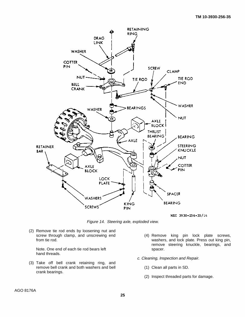
Figure 14. Steering axle, exploded view.
(2) Remove tie rod ends by loosening nut andscrew through clamp, and unscrewing endfrom tie rod.
Note. One end of each tie rod bears lefthand threads.
(3) Take off bell crank retaining ring, andremove bell crank and both washers and bellcrank bearings.
(4) Remove king pin lock plate screws,washers, and lock plate. Press out king pin,remove steering knuckle, bearings, andspacer.
c. Cleaning, Inspection and Repair.
(1) Clean all parts in SD.
(2) Inspect threaded parts for damage.
AGO 8176A25

TM 10-3930-256-35
Inspect all bearings for wear. If practicable,repair damaged threads with a tap orthread chaser. Replace all unserviceableparts at assembly.
d. Lubrication and Assembly.
(1) Pack all bearings with grease, GAA.(2) Reverse procedure in b above.
e. Installation. Reverse procedure in a above.f. Adjustment. Adjust tie rods (TM 10-3930- 256-20).
17. Steering Knuckles, Pins and Bearings
Refer to paragraph 16 for removal and installation ofsteering knuckles, pins and bearings.
Section V. BRAKES
18. GeneralThis section covers direct and generalsupport maintenance of the service(wheel) brake system.
19. Parking Brake SystemMaintenance of the parking brake system is coveredin TM 10-3930-256-20.
20. Brake Assemblya. Removal.
(1) Perform paragraph 12a, less step (5), to getaccess to brake assembly.
(2) Hold antirattle pin (fig. 15) with fingertip frombehind backing plate, press outer springretainer in, to compress spring, turnretainer a quarter turn either way andremove spring, both retainers, and pin.Repeat at other brake shoe.
(3) With brake spring pliers, remove shoe returnspring, retaining spring and both brakeshoes.
(4) Remove screws and washers and removewheel cylinder.
b. Wheel Cylinder Repair.
(1) Remove cylinder by performing aabove.
(2) Remove boots and push rods (fig. 15)fromcylinder.
(3) Remove spring, pistons and cups.
(4) Inspect bore of cylinder, and pistons for pitsor scoring. Hone cylinder bore clean if minorpits are present. If bore cannot be cleanedup readily,
install complete new cylinder assembly.
(5) Clean all metal parts in alcohol, drythoroughly, and install cylinder repair kit.Assemble by reversing a(3), to b(1)above.
c. Cleaning (Except wheel cylinder).
(1) Remove dust from assembly with com-pressed air and stiff bristle brush.
(2) If brake fluid has leaked onto assembly,replace brake linings (d below), andwash off fluid with alcohol.
(3) If axle lubricant has leaked onto assembly,replace oil seal (fig. 7), per paragraph13, replace brake linings, and cleanparts with SD.
Caution: Do not get SD on anyrubber brake parts. It will cause themto swell and rot.
d. Brake Shoe Repair. Install new bonded lining onbrake shoes, when less than 1/ inch of lining remains, atthinnest point. Apply lining in accordance with goodpractice, and instructions for use of equipment available.
e. Installation. Reverse a above. Adjust brake liningclearance and bleed air from brakes (TM 10-3930-256-20).
21. Brake Master Cylinder
a. Removal. Refer to TM 10-3930-256-20.
b. Disassembly.(1) Remove push rod and bellows (fig.
16).(2) Remove retaining ring from cylinder. Take
out piston stop, piston, primary cup,spring and check valve.
AGO 8176A
26
TM 10-3930-256-35
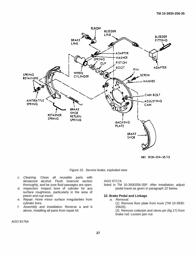
Figure 15. Service brake, exploded view
c. Cleaning. Clean all reusable parts withdenatured alcohol. Flush reservoir sectionthoroughly, and be sure fluid passages are open.
d. Inspection. Inspect bore of cylinder for anysurface roughness, particularly in the area ofpiston and cup travel.
e. Repair. Hone minor surface irregularities fromcylinder bore.
f. Assembly and Installation. Reverse a and babove, installing all parts from repair kit
AGO ST17Alisted in TM 10-3930256-35P. After installation, adjust
pedal travel as given in paragraph 22 below.
22. Brake Pedal and Linkagea. Removal.
(1) Remove floor plate from truck (TM 10-3930-25620).(2) Remove cotterpin and clevis pin (fig.17) frombrake rod. Loosen jam nut
AGO 8176A
27

TM 10-3930-256-35
Figure 16. Brake master cylinder, exploded view
and unscrew brake rod from master cylinder push rod.
(3) Remove screws, nuts, and washers attachingshaft, lift entire assembly free of truck.
b. Installation and Adjustment.
(1) Reverse a above.(2) Bleed brakes and adjust lining clear-
ance (TM 10-3930-256-20).(3) Adjust pedal free travel to 1/4 inch to 5/8 inchby turning master cylinder push rod (fig. 16) onthreads of brake rod (fig. 17). Tighten jam nut tobrake rod to secure adjustment.
AGO 8176A
28

TM 10-390-256-35
Figure 17. Brake pedal and linkage, exploded view.
Section VI. WHEELS
23. Wheels
Refer to TM 10-3930-256-20 for removal andinstallation of wheels.
24. Tires
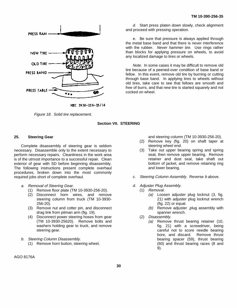
Replacement is usually made by pressing off old tiresimultaneously with pressing on new one. Pressurerequired to install tire is 5000 pounds for each inch ofwheel diameter. For example, a tire used on a wheel of18 inches diameter requires 18 x 5000 pounds, or 45tons
press capacity for replacement. Using a press ofadeqaute capacity, proceed as follows:
a. Remove wheel on which tire is to be replaced(TM 10-3930-256-20).
b. As shown in figure 18, support felloe of wheelwith ring just slightly smaller in diameter than wheelfelloe and at least as wide as tire to be pressed off.
c. Place new tire over the old, and center carefully.
AGO 8176A
29
TM 10-390-256-35
Figure 18. Solid tire replacement.
d. Start press platen down slowly, check alignmentand proceed with pressing operation.
e. Be sure that pressure is always applied throughthe metal base band and that there is never interferencewith the rubber. Never hammer tire. Use rings ratherthan blocks for applying pressure on wheels, to avoidany localized damage to tires or wheels.
Note. In some cases it may be difficult to remove oldtire because of a peened-over condition of base band orfelloe. In this event, remove old tire by burning or cuttingthrough base band. In applying tires to wheels withoutold tires, take care to see that felloes are smooth andfree of burrs, and that new tire is started squarely and notcocked on wheel.
Section VII. STEERING
25. Steering Gear
Complete disassembly of steering gear is seldomnecessary. Disassemble only to the extent necessary toperform necessary repairs. Cleanliness in the work areais of the utmost importance to a successful repair. Cleanexterior of gear with SD before beginning disassembly.The following instructions present complete overhaulprocedures, broken down into the most commonlyrequired jobs short of complete overhaul.
a. Removal of Steering Gear.(1) Remove floor plate (TM 10-3930-256-20).(2) Disconnect horn wires, and remove
steering column from truck (TM 10-3930-256-20).
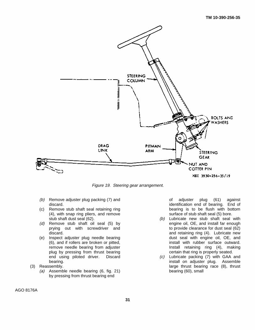
(3) Remove nut and cotter pin, and disconnectdrag link from pitman arm (fig. 19).
(4) Disconnect power steering hoses from gear(TM 10-3930-25620). Remove bolts andwashers holding gear to truck, and removesteering gear.
b. Steering Column Disassembly.(1) Remove horn button, steering wheel,
and steering column (TM 10-3930-256-20).(2) Remove key (fig. 20) on shaft taper at
steering wheel end.(3) Take out upper bearing spring and spring
seat, then remove upper bearing. Removeretainer and dust seal, take shaft outbottom of jacket, and remove retaining ringand lower bearing.
c. Steering Column Assembly. Reverse b above.
d. Adjuster Plug Assembly.(1) Removal.
(a) Loosen adjuster plug locknut (3, fig.21) with adjuster plug locknut wrench(fig. 22) or equal.
(b) Remove adjuster ,plug assembly withspanner wrench.
(2) Disassembly.(a) Remove thrust bearing retainer (10,
fig. 21) with a screwdriver, beingcareful not to score needle bearingbore, and discard. Remove thrustbearing spacer (59), thrust bearing(60) and thrust bearing races (8 and9).
AGO 8176A
30
TM 10-390-256-35
Figure 19. Steering gear arrangement.
(b) Remove adjuster plug packing (7) anddiscard.
(c) Remove stub shaft seal retaining ring(4), with snap ring pliers, and removestub shaft dust seal (62).
(d) Remove stub shaft oil seal (5) byprying out with screwdriver anddiscard.
(e) Inspect adjuster plug needle bearing(6), and if rollers are broken or pitted,remove needle bearing from adjusterplug by pressing from thrust bearingend using piloted driver. Discardbearing.
(3) Reassembly.(a) Assemble needle bearing (6, fig. 21)
by pressing from thrust bearing end
of adjuster plug (61) againstidentification end of bearing. End ofbearing is to be flush with bottomsurface of stub shaft seal (5) bore.
(b) Lubricate new stub shaft seal withengine oil, OE, and install far enoughto provide clearance for dust seal (62)and retaining ring (4). Lubricate newdust seal with engine oil, OE, andinstall with rubber surface outward.Install retaining ring (4), makingcertain that ring is properly seated.
(c) Lubricate packing (7) with GAA andinstall on adjuster plug. Assemblelarge thrust bearing race (8), thrustbearing (60), small
AGO 8176A
31

TM 10-390-256-35
Figure 20. Steering column, cutaway view.
1 Bolt 32 Washer2 Flange 33 Oil seal3 Nut 34 Oil seal4 Retaining ring 35 Rack-piston-nut5 Oil seal 36 Packing6 Needle bearing 37 Piston ring7 Packing 38 End plug8 Race 39 Housing end plug9 Race 40 Retaining ring
10 Bearing retainer 41 Packing11 Packing 42 Balls12 Spring 43 Ball guide13 Sector gearshaft 44 Clamp14 Connector 45 Screw15 Connector 46 Housing16 Thrust bearing races 47 Washer17 Worm 48 Lash adjuster18 Packing 49 Washer19 Torsion bar and valve 50 Retainer
cup 51 Sleeve bearing20 Stub shaft 52 Side cover21 Valve body 53 Nut22 Valve body rings 54 Screw23 Back-up packing 55 Washer24 Pin 56 Packing25 Bearing 57 Spool26 Ball 58 Spool spring27 Bearing 59 Spacer28 Washers 60 Thrust bearing29 Retaining ring 61 Adjuster plug30 Steering arm 62 Dust seal31 Nut
Figure 21. Steering gear, exploded view.
thrust bearing race (9), and thrustbearing spacer (59) on adjuster plug.Press new retainer (10) into needlebearing bore, using thrust bearingretainer installer, as shown in fig. 23.
(4) Installation.(a) Place seal protector tool over end of
stub shaft (20, fig. 21).(b) Install adjuster plug assembly in gear
housing. Adjust thrust bearing preloadaccording to k (1) below, and tightenlocknut to 50 to 110 foot pounds.
e. Valve Assembly. The complete valve assemblyin each steering gear is a precision unit with selectivefitted parts and is hydraulically balanced at assembly.Only those parts which are service items are replaceableand interchangeable. No other valve parts areindividually interchangeable. If replacement of anynonserviceable valve part is necessary, the completerotary valve assembly must be replaced.
Note. It is very uncommon to have to make anyservice repairs of the valve assembly with the exceptionof the valve spool dampener packing. Do notdisassemble valve unless necessary since this mayresult in damag-
AGO 8176A32

TM 10-390-256-35
Figure 21. Steering gear, exploded view-Continued.
AGO 8176A
33

TM 10-390-256-35
Figure 22. Adjuster plug locknut wrench.
Figure 23. Thrust bearing retainer installer.
AGO 8176A
34

TM 10-390-256-35
ing the assembly. If valve spool dampener packingrequires replacement, remove valve spool only, replacepacking, and reinstall spool immediately. Do notdisassemble further.
(1) Removal.(a) Remove adjuster plug assembly as
outlined under d above.(b) Remove valve assembly from gear by
grasping stub shaft (20, fig. 21) andpulling out valve assembly and stubshaft.
(2) Disassembly.(a) Remove packing (18, fig. 21) and
discard.(b) Remove spool spring (58) by prying
small coil, using small screwdriver.Caution: Do not pry against valve
body (21), as this may result in asticky valve. Work spring ontobearing diameter of stub shaft (20).Slide spring off stub shaft.
(c) Remove valve spool (57) with extremecare.
Caution: The diametral clearancebetween valve body and spool may beas low as 0.0004 inches. Theslightest cocking of spool may jam it invalve body. To remove valve spool(57), hold valve assembly in bothhands with stub shaft pointingdownward. Push lightly on valve spoolwith a small rod by inserting rodthrough openings in valve cap (19)until spool is far enough out of valvethat it may be grasped by the hand.Withdraw spool with a steadyoscillating pull to prevent jamming. Ifslight sticking occurs, make a gentleattempt to reverse withdrawalprocedure. If this does not free spool,it has become cocked in valve bodybore. Do not attempt to force spool inor out if it becomes cocked. In thiscase, continue to disassemble valveassembly as follows and return to thespool as described in (e) below.
(d) Remove stub shaft (20), torsion barand valve cap assembly (19) byholding valve assembly in both
hands as before, only with thumbs onvalve body. Rap torsion bar lightlyagainst work bench. This will dislodgethe cap from the valve body to cap pin.The stub shaft, torsion bar and valvecap assembly can now be removedfrom valve body. If valve spool hasbecome cocked as described in (c)above, it can now be freed. By visualinspection on a flat surface it can bedetermined in which direction spool iscocked. A few very light taps with alight soft plastic or rawhide malletshould align spool in the bore and freeit.
Caution: Do not tap with anythingmetallic. If spool can be rotated, it canbe removed.
(e) Remove dampener seal packing (11)from spool and discard.
(d) Providing rings show evidence ofexcessive wear, carefully cut valverings (22) and ring back-up packing(23), remove and discard. The valverings are made of filled teflon and it isvery unusual that replacement isrequired.
(3) Inspection.(a) If valve assembly leaks externally
around torsion bar, replace entireassembly.
(b) Check pin in valve body (21, fig. 21)which engages cap. If it is badlydamaged, entire valve assembly mustbe replaced.
(c) Check worm pin groove (the smallerof the two) in valve body. If it isdamaged, entire valve assembly mustbe replaced.
(d) Check spool drive pin in stub shaft. Ifit is worn badly, cracked or broken,entire valve assembly must bereplaced.
(e) Examine spool (57) surface for nicksand burrs. If any are found, they mustbe removed with a very fine hone. Aslight polishing is normal on valvingsurfaces.
(f) Examine valve body fore for nicks
35

TM 10-390-256-35
or burrs. If any are found, they can beremoved with light crocus cloth untilspool turns freely in body. Be carefulnot to remove any stock from surfaceof body. As on the spool, a slightpolishing is normal on valvingsurfaces.
(4) Reassembly.(a) Lubricate valve ring back-up packings
(23) in OE. Assemble in three ringgrooves on valve body. Assemblevalve rings (22) in ring grooves overback-up packings by carefully slippingrings over valve body. The rings mayappear loose or twisted in the grooves,but the heat of the oil after assemblywill cause them to tighten.
(b) Install new valve spool dampenerpacking in valve spool groove.
(c) Assemble stub shaft in valve body.Align groove in valve cap with pin invalve body. Tap lightly on cap withplastic or rawhide mallet until cap isagainst shoulder in valve body withvalve body pin in cap groove.
Caution: Make sure groove andpin are in line before tapping on cap.Hold these parts together during restof assembly.
(d) Lubricate valve spool with OE. Slidespool over stub shaft with notchtoward valve body. Align notch withspool drive pin in stub shaft andcarefully engage spool in valve bodybore.
Caution: Because clearancebetween spool and valve body is verysmall, extreme care must be takenwhen assembling these parts. Pushspool evenly and slowly with a slightoscillating motion until spool reachesdrive pin. Rotate spool slowly withpressure until notch engages pin.Before pushing spool completely in,make sure dampener packing isevenly distributed in spool groove.Slowly push spool completely in, withextreme care taken not to cut or pinchpacking.
(e) Place seal protecting tool over stubshaft. Slide spool spring over sealprotector and work spool spring downuntil it is seated in stub shaft groove.Take care not to mar sealing surfaceof stub shaft.
(f) Lubricate new cap-to-worm packing inOE and install in valve assembly.
(g) If during assembly of valve, stub shaftand cap assembly is allowed to slipout of engagement with valve bodypin, spool may enter valve body toofar. The dampener packing willexpand into valve body oil grooves,preventing withdrawal of spool.Attempt to withdraw spool with slightpull and much rotary motion. If thisdoes not free spool after several tries,make sure spool is free to rotate;place valve body on flat surface withnotched end up, and tap spool withwooden or plastic rod until packing iscut and spool can be removed.Replace packing and proceed withassembly as before.
(5) Installation.(a) Align valve body drive pin in worm (17,
fig. 21) with narrow pin slot on valvebody. Insert valve assembly into gearhousing.
Caution: Do not push againststub shaft as this may cause stubshaft and cap to pull out of valve body,allowing spool seal to slip into valvebody oil grooves as described in thepreceding section. Valve assemblyshould be pushed in by pressingagainst valve body with finger tips. Besure valve is properly seated beforeassembling adjuster plug assembly.Return hole in gear housing should befully visible at this time.
(b) Install adjuster plug assembly asoutlined in d above.
f. Sector Gearshaft Assembly and Side Cover.(1) Removal of pitman shaft seals with gear in
truck.
AGO 8176A
36

TM 10-390-256-35
(a) Remove steering arm nut (81, fig. 21),lockwasher (32), and steering arm(30). Place an oil-catch basin beneathsteering gear.
(b) Remove sector gearshaft sealretaining ring (29), and outer sealback-up washer (28).
(c) With steering pump running, andhoses attached, momentarily holdsteering wheel in extreme left turnposition. This actuates valve, allowingpressure to build up on upper side ofpiston, and in gearshaft chamber,thereby forcing out seals (33 and 34)and inner seal back-up washer (28).To prevent undue oil loss and pumpwear, do not hold wheel for more thana second or two at a time.
(d) Turn off steering pump. Removeseals and inner back-up washer fromshaft and discard seals.
(2) Removal of sector gearshaft and sidecover.(a) Disconnect hoses and remove
steering gear from truck.(b) Drain out as much of remaining oil as
possible.(c) Rotate stub shaft (20, fig. 21) until
sector gearshaft (13) is in centerposition and remove side coverretaining screws (54). Tap end ofgearshaft with soft mallet and slidegearshaft out of housing.
(d) Remove side cover packing (56) fromside cover and discard.
(3) Disassembly.(a) Hold lash adjuster (48, fig. 21) with a
hex key wrench and remove lashadjuster nut (53) and discard. Screwlash adjuster out of side cover (52).
(b) Remove sector gearshaft sealretaining ring (29), and outer backupwasher (28). Tap a screwdriverbetween outer seal and inner backupwasher and pry out seal. Tap thescrewdriver between inner seal andshoulder in gear housing and pry outseal. Be careful not to damage sealbore. Discard seals.
(c) Remove needle bearing (27) fromgear housing bore by pressing on thestamped identification end of bearing.Discard bearing.
(4) Inspection.(a) Inspect sleeve bearing (51, fig. 21) in
side cover (52) for excessive wear orscoring. If badly worn or scored,replace side cover and bearing as anassembly.
(b) Check sector gearshaft teeth andbearing and seal surfaces. If badlyworn, pitted, or scored, replacegearshaft assembly.
(c) Check needle bearing (27) in housing.(5) Assembly.
(a) Assemble new needle bearing (27, fig.21) into gear housing (46) bore fromseal bore end, pressing againststamped identification end. Press inuntil bearing clears shoulder in gearhousing 0.030 inch maximum.
(b) Lubricate new gearshaft seals in OE.Install single lip seal first, then a back-up washer. Drive seal and washer infar enough to provide clearance forother seal, back-up washer, andretaining ring (29). Seal must notbottom on end of counterbore. Installdouble lip seal and second back-upwasher. Drive seal and back-upwasher in only far enough to provideclearance for retaining ring. Installsector gearshaft retaining ring. Becertain this ring is seated properly.
(c) Assemble side cover (52) and bearing(51) assembly on sector gearshaftassembly. Screw lash adjuster (48)through side cover until side coverbottoms on gearshaft, and back off 1/2turn.
(5) Installation.(a) Lubricate new side cover packing (56,
fig. 21) and install in groove in face ofside cover.
(b) Turn stub shaft (20) as necessary untilmiddle rack groove is aligned withcenter of gearshaft needle bearing(27).
AGO 8176A
37

TM 10-390-256-35
(c) Install gearshaft so that center tooth insector gear meshes with centergroove of rack-piston (35). Make surethat side cover packing is in placebefore pushing side cover down ongear housing.
(d) Install side cover screws (54) andtighten to 30 to 35 foot pounds.
(e) Install lash adjuster nut (53) on lashadjuster without tightening. Adjustgearshaft per specification. Hold lashadjuster from rotating with a hex keywrench and tighten lash adjuster nutto 20 to 30 foot pounds.
g. Housing End Plug.(1) Removal.
(a) Rotate end plug retainer ring (40, fig.21) so that one end of ring is over holein housing. Spring one end of ringwith punch to allow screwdriver to beinserted to lift ring out.
(b) Rotate stub shaft (20) to left turncorner position and force end plug(39) out of housing.
Caution: Do not rotate furtherthan necessary or the balls from therack and worm assembly will fall offend of worm.
(c) Remove and discard housing end plugpacking (41).
(2) Installation.(a) Lubricate new housing end plug
packing (41) with OE and install ingear housing (46).
(b) Insert housing end plug (39) into gearhousing and seat against packing.
(c) Install end plug retainer ring (40) withfingers. Install one end of ring andwork ring into groove until seated.Slight tapping may be required tosecurely bottom retainer ring in gearhousing.
h. Rack-Piston End Plug.(1) Removal.
(a) Remove housing end plug as outlinedunder g (1) above.
(b) Remove rack-piston end plug (38, fig.21).
(2) Installation.(a) Turn plug into rack-position and
tighten to 50 or 100 foot pounds.(b) Install housing end plug as outlined
under g (2) above.
i. Rack-Piston and Worm Assembly and GearHousing Assembly.
(1) Removal.(a) Remove housing end plug as outlined
under g (1) above.(b) Remove rack-piston end plug as
outlined under h (1) above.(c) Remove sector gearshaft assembly as
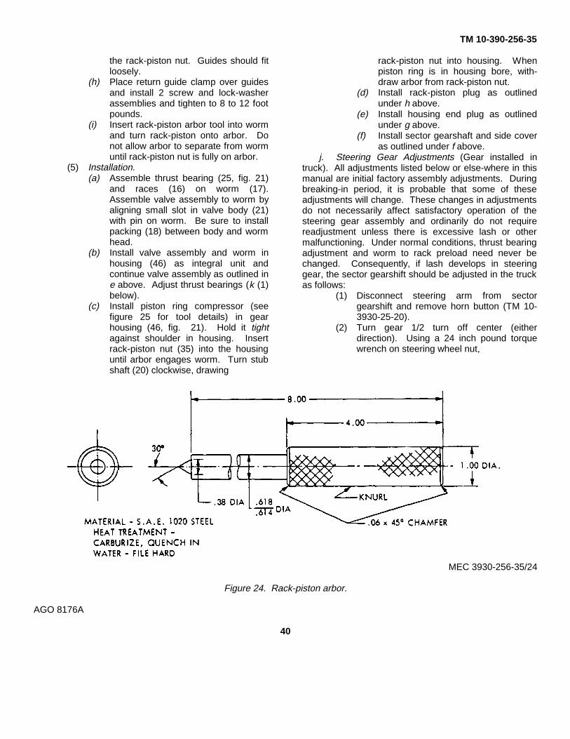
outlined under f (2) above.(d) Insert rack-piston arbor (see figure 24
for tool details) in end of worm (17, fig.21). Rotate stub shaft to left turn,which will force rack-piston nut (35)onto arbor, and remove rack-pistonnut from gear housing, taking care tokeep arbor in place in rack-piston nutor the balls will fall out. If rack-pistonnut is being removed to replace pistonring (37, fig. 21) and back-up packing(36), reassemble without furtherdisassembly.
(e) Remove valve assembly as outlinedunder e above.
(f) Remove worm, lower thrust bearingand races.
(2) Disassembly.(a) Refer to (3) below.(b) Cut piston ring (37, fig. 21) and
packing (36) back-up seal, removefrom rack-piston nut (35) and discard.
(c) Remove screws and lock washers(45) from rack-piston nut withscrewdriver.
(d) Remove ball return guide clamp (44).(e) Place assembly on a clean cloth and
remove ball return guides (43) andarbor. Make sure all of the balls (42)are caught on the cloth.
(3) Inspection(a) Inspect housing assembly. If bore
AGO 8176A
38

TM 10-390-256-35
is badly scored or worn, replacehousing. If connectors (14 and 15, fig.21) are badly brinelled or scored,replace them. To remove connectors,tap threads using a 5/6-18 tap.Thread a bolt with a nut and flatwasher attached into tapped hole. Topull connector, hold bolt from rotatingwhile turning nut off bolt. This will pullthe connector from gear housing.Discard connectors.
(b) Inspect ball plug (26) in housing. If itis leaking or raised above housingsurface, it may be driven in flush to1/16 inch below the surface. The ballcan be tightened by staking thehousing. If leakage cannot bestopped, housing must be replaced.
(c) Inspect all seal surfaces and retainingring grooves for defects. If anydefects are found, housing must bereplaced.
(d) At initial assembly, rack-piston nut,worm and balls are selected to obtaina preload of 1 to 4 inch poundsmeasured on center through an angleof 90°. This preload may drop duringservice, but this will not have anynoticeable effect on steering, andordinarily will not need any refitting togain preload. The preload may bechecked, if so desired, by using themethod described under j below.Upon complaint of loose or hardsteering, thrust bearing adjustmentand overcenter adjustment will correctthe problem if it lies in steering gearadjustments. If not, check rack-pistonnut and worm assembly for excessivelash or excessive load overcenter andalso for roughness at any point alongthe worm. If any of these conditions isfound, disassemble the assembly andinspect worm and rack-piston nutgrooves and all the balls for excessivewear or scoring. If either worm orrack-piston nut need replacing, bothmust be replaced as a matchedassembly. The lash or
heavy load may be corrected byreplacing standard balls with a largeror smaller size-black balls need not bereplaced unless they are defective. Inevent black balls cannot bedistinguished from standard balls,replace with new balls using methoddescribed under (4) (f) below.
(e) Inspect ball return guides (43), makingsure that the ends where balls enterand leave guides are not damaged.
(f) Inspect lower thrust bearing andraces.
(g) Inspect rack-piston nut teeth for wearand chipping. Inspect rack-piston nutsurface for scoring or burrs.
(4) Reassembly.(a) Thoroughly clean parts and lubricate
internal parts with OE.(b) Drive new connectors (14 and 15, fig.
21) in place with piloted driver.(c) Lubricate new back-up packing (36)
with OE. Assemble in piston ringgroove on rack-piston nut (35). Installnew piston ring (37) in ring grooveover the packing by carefully slippingring over rack-piston nut. The ringmay be slightly loose after assembly.This is normal and it will tighten whensubjected to the hot oil in the system.
(d) Insert worm (17) into rack-piston nut,to bearing shoulder.
(e) Align ball return guide holes with wormgroove. Load 16 balls (42) into guidehole nearest piston ring, while slowlyrotating worm (17) counterclockwise tofeed balls through circuit. Alternateblack balls with standard balls.
(f) Fill one ball return guide withremaining 6 balls. Place other guideover balls and plug ends with grease,GAA, to prevent balls from falling outwhen installing guide into rack-pistonnut.
(g) Insert guides into guide holes of
AGO 8176A
39
TM 10-390-256-35
the rack-piston nut. Guides should fitloosely.
(h) Place return guide clamp over guidesand install 2 screw and lock-washerassemblies and tighten to 8 to 12 footpounds.
(i) Insert rack-piston arbor tool into wormand turn rack-piston onto arbor. Donot allow arbor to separate from wormuntil rack-piston nut is fully on arbor.
(5) Installation.(a) Assemble thrust bearing (25, fig. 21)
and races (16) on worm (17).Assemble valve assembly to worm byaligning small slot in valve body (21)with pin on worm. Be sure to installpacking (18) between body and wormhead.
(b) Install valve assembly and worm inhousing (46) as integral unit andcontinue valve assembly as outlined ine above. Adjust thrust bearings (k (1)below).
(c) Install piston ring compressor (seefigure 25 for tool details) in gearhousing (46, fig. 21). Hold it tightagainst shoulder in housing. Insertrack-piston nut (35) into the housinguntil arbor engages worm. Turn stubshaft (20) clockwise, drawing
rack-piston nut into housing. Whenpiston ring is in housing bore, with-draw arbor from rack-piston nut.
(d) Install rack-piston plug as outlinedunder h above.
(e) Install housing end plug as outlinedunder g above.
(f) Install sector gearshaft and side coveras outlined under f above.
j. Steering Gear Adjustments (Gear installed intruck). All adjustments listed below or else-where in thismanual are initial factory assembly adjustments. Duringbreaking-in period, it is probable that some of theseadjustments will change. These changes in adjustmentsdo not necessarily affect satisfactory operation of thesteering gear assembly and ordinarily do not requirereadjustment unless there is excessive lash or othermalfunctioning. Under normal conditions, thrust bearingadjustment and worm to rack preload need never bechanged. Consequently, if lash develops in steeringgear, the sector gearshift should be adjusted in the truckas follows:
(1) Disconnect steering arm from sectorgearshift and remove horn button (TM 10-3930-25-20).
(2) Turn gear 1/2 turn off center (eitherdirection). Using a 24 inch pound torquewrench on steering wheel nut,
MEC 3930-256-35/24
Figure 24. Rack-piston arbor.
AGO 8176A
40

TM 10-390-256-35
Figure 25. Piston ring compressor.
determine torque required to rotate shaftslowly through a 20° arc.
(3) Turn gear back to center and repeatingmethod of reading torque as in (2) above,loosen adjuster nut, turn screw in untilreading is equal to 6 inch pounds in excessof (2) above, and retighten locknut whileholding screw in place.
(4) Recheck readings and replace steering armand horn button.
k. Gear Adjustments after Disassembly.(1) Thrust bearing adjustment. This
adjustment is to be made after worm,
thrust bearings, valve assembly, adjusterplug assembly, and locknut are assembledin housing assembly. Proceed as follows:(a) Before adjusting preload, tighten
adjuster plug up snug, back off slightly(1/8 turn) and measure valveassembly drag.
(b) Turn adjuster plug in so that preload is1 to 3 inch pounds in excess of valveassembly drag. Tighten locknut.Total thrust bearing adjustment andseal drag is not to exceed 8 inchpounds.
AGO 8176A
41
TM 10-390-256-35
(2) Worm and rack-piston nut adjustment.Select fit of worm, rack-piston nut and ballsto provide some preload not to exceed 41/2inch pounds measured on center of worm.
(3) Overcenter or sector gearshift adjustment.This adjustment is to made after gear iscompletely assembled. With gear oncenter and lash adjuster backed off,measure total drag. With gear on center,adjust lash adjuster so that preload is 4 to 8inch pounds in excess of total preload anddrag. Readings are to be made through anarc not exceeding 20° with gear on center.Tighten lash adjuster locknut.
l. Adjustment If Not Disassembled.(1) Thrust bearing adjustment.
(a) Turn gear into either right or left cornerand back off 1/4 turn.
(b) Before adjusting preload, tightenadjuster plug up snug, back off slightly(1/8 turn) and measure valveassembly drag.
(c) Turn adjuster plug in so that pre- loadis 1 to 3 inch pounds in excess ofvalve assembly drag. Tighten locknut.
(d) Total thrust bearing adjustment andseal drag is not to exceed 8 inchpounds.
(2) Overcenter or lash adjuster adjustments.With gear on center and lash adjusterbacked off, measure total drag. With gearon center, adjust lash adjuster so thatpreload is 4 to 8 inch pounds in excess oftotal preload and drag. Readings are to bemade through an arc not exceeding 20°with gear on center. Tighten locknut.
m. Troubleshooting.(1) Hard steering while driving.
Probable cause RemedyFrozen sector gearshaft bearings-------------------------------Replace bearings.Lower coupling flange rubbing against adjuster ------------Loosen bolt and assemble properly.Steering wheel rubbing against mast jacket -----------------Adjust jacket endwise.Steering adjustment tight -----------------------------------------Check adjustment by dropping steering arm from gear
or disconnecting linkage from drag link. Readjust ifnecessary.
(2) Poor return of steering.Probable cause Remedy
Frozen sector gearshaft bearings-------------------------------Replace bearings.Lower coupling flange rubbing against adjuster -------------Loosen bolt and assemble properly.Steering wheel rubbing against mast jacket------------------Adjust jacket endwise.Incorrect wheel alignment ----------------------------------------Adjust to specification.Tight steering linkage ----------------------------------------------Lubricate.Steering adjustment tight -----------------------------------------Check adjustment by disconnecting drag link from steer-
ing arm. Readjust if necessary.Sticky valve spool---------------------------------------------------Remove and clean valve or replace valve.
(3) Momentary increase in effort when turning wheel fast to the left or right.Probable cause Remedy
Low oil level in pump-----------------------------------------------Check oil level in pump reservoir.High internal leakage ----------------------------------------------Replace rack-piston ring and back-up packing, rack-
piston end plug, valve body to worm seal and/orreplace valve.
(4) External oil leaks (wipe gear thoroughly and make sure source of leakage is determined).Probable cause Remedy
Loose hose connections ------------------------------------------Tighten.Damaged hose ------------------------------------------------------Replace.Side cover packing -------------------------------------------------Replace seal.Sector gearshaft seals---------------------------------------------Replace seals.Housing end plug seal ---------------------------------------------Replace seal.Adjuster plug seals -------------------------------------------------Replace seal.Torsion bar seal -----------------------------------------------------Replace valve.
AGO 8176A
42

TM 10-390-256-35
(5) Gear noise (rattle or chuckle).Note: A slight rattle may occur on turns because of the increased lash off the "high point". This is normal.
Probable cause RemedyLoose overcenter adjustment ------------------------------------Adjust to specification.Gear loose on frame -----------------------------------------------Check gear-to-frame mounting bolts. Tighten bolts to
specifications.(6) Gear noise ("hissing" sound).
Probable cause RemedyThere is some noise in all power steering systems. Do not replace valve unless "hiss" is extremely objectionable.
One of the most common is a "hissing" sound most Slight hiss is satisfactory and in no way affects steering. Aevident at standstill parking. There is no relation- replacement valve may also exhibit slight noise and is notship between this noise and performance of the always a cure for the objection. Be sure steering shaft andsteering. "Hiss" may be expected when steering gear are aligned so the flexible coupling rotates in a flat planewheel is at end of travel, or when slowly turning and is not distorted as shaft rotates. Any metal-to-metalat standstill. contact through the flexible coupling will transmit the valve
hiss.(7) Excessive wheel kickback or loose steering.
Probable cause RemedyLash in steering linkage -------------------------------------------Adjust parts affected.Excessive lash between sector gearshaft and rack- Adjust to specifications.
piston.Loose thrust bearing adjustment--------------------------------Remove gear and adjust to specification.Ball nut and worm preload----------------------------------------Remove rack-piston and worm, and change balls to obtain
specified preload.(8) Hard steering when parking.
Probable cause RemedyLow oil level in reservoir-------------------------------------------Fill to proper level. If excessively low, check all lines
and joints for evidence of external leakage.Lack of lubrication in linkage -------------------------------------Add lubricant where needed.Insufficient oil pressure-------------------------------------------- If all of the above checks do not reveal the cause of hard
steering, make the following tests of oil pressure:A. Disconnect the pressure line at oil pump. Attach gauge to
pump. Connect the hose to end of gauge where the valve islocated.
B. With engine at warm idle and gauge valve open, note the oilpressure on the gauge while turning steering wheel fromone extreme position to the other. Especially note themaximum pressure which can be built up with the wheelheld in either right or left extreme position.Caution: Do not hold wheel in extreme position for anextended period of time because it will drastically increasethe oil temperature and will cause undue wear on the oilpump.
C. With oil temperature between 150°F. and 170°F. asmeasured with a thermometer in the reservoir, themaximum oil pressure should not be less than 925 psi forsatisfactory power steering operation.
D. If the maximum oil pressure is less than 925 psi, it indicatestrouble in the pump, oil hoses, steering gear, or acombination of these parts. To eliminate the hoses andgear, close the gauge valve and quickly test pressure of thepump only with the engine at warm idle, then open the valveto avoid increasing oil temperature.
E. Comparing the maximum pressures obtained in these twotests will indicate source of trouble as follows:
AGO 8176A
43

TM 10-390-256-35
Probable cause Remedy1. First test (step B) pressure low, and second test (step D)
pressure normal indicates faulty external oil lines orsteering gear.
2. First test (step B) and second test (step D) pressureequally low-indicates faulty oil pump.
If above test shows trouble to be in pump, see paragraph28. If trouble is shown to be in steering gear or hoses,examine for external oil leaks.
Low oil pressure due to restriction in hoses-(A) Check for kinks in hoses -------------------------------Remove kink.(B) Foreign object stuck in hose --------------------------Remove hoses and remove restricting object or replace
hose.Low oil pressure due to steering gear-
(A) Pressure loss in cylinder due to worn piston Remove gear from truck for disassembly and inspectionring or scored housing bore. of piston ring, back-up seal, and housing bore.
(B) Leakage at valve rings, valve body to worm Remove gear from truck for disassembly and repair.seal, rack-piston end plug.
(C) Leaky valve body-----------------------------------------Replace valve.(9) Valve squawk when turning or when recovering from a turn.
Probable cause RemedyCut or worn dampener ring on valve spool -------------------Replace dampener ring, being careful not to cut the new
ring at installation.Loose or worn valve------------------------------------------------Replace valve.
(10) No effort required to turn.Probable cause Remedy
Broken torsion bar --------------------------------------------------Replace valve.
26. Tie Rods
a. Removal. Remove cotter pin and nut from eachtie rod end (fig. 26), and remove tie rod ends fromsteering knuckles and bell crank.
b. Installation. Reverse a above.
c. Adjustment. Refer to TM 10-3930-256-20.
27. Bell Crank
a. Removal.(1) Remove steering axle (para. 16a).(2) Remove retaining ring and upper washer
(fig. 26) and lift bell crank from axle.
b. Disassembly. Refer to para 16b(3).
c. Assembly. Reverse para. 16b(3).
d. Installation. Reverse a above.
28. Steering Pump
a. Removal and Installation. Refer to TM 10-3930-256-20.
b. Disassembly. Note. Discard all used packingsand shaft seal (fig. 27).
(1) Remove discharge fitting (fig. 27) and drawreservoir from pump.
(2) Clamp pump mounting flange in a vise withprotective jaws. Remove cover mountingscrews. Take cover from pump body.Remove pressure plate and spring.
(3) Remove adapter plate and related packingsshown.
(4) Remove pump ring, locating pins, rotor andvanes, and pump ring packing.
(5) Mount cover in vise. Drive out retaining pinwith pin punch.
Caution: Be careful that relief valveparts do not fall from bore.
(6) Take plug and packing, valve and springfrom bore. These parts are accessiblethrough large hole inside cover.
(7) Remove gearshaft and seal from pumpbody.
Note. Shaft bushing in body is not tobe serviced separately. If bushing is worn,replace pump body.
AGO 8176A
44

TM 10-390-256-35
Figure 26. Tie rods and bell crank.
c. Cleaning.(1) Thoroughly clean all parts in SD. Dry with
compressed air.(2) Thoroughly clean all internal passages of
pump cover, housing, and body.
d. Inspection, Repair, Replacement.(1) Ring, rotor, vanes, pressure plate, body.
Inspect surfaces of all parts which aresubject to wear. Light scoring may beremoved from faces of body or wear platewith crocus cloth (by placing cloth on flatsurface), medium India stone or by lapping.Check edges of vanes for wear. Vanesmust not have excessive play in slots orburrs on edges. Replace if necessary.Check each rotor slot for sticky vanes orwear. Vanes should drop in rotor slots bytheir own weight when both slot and vaneare dry.
(2) Relief valve. Insert valve in its bore inpump cover. There should be no binding.Check valves and bore for excessive wearand scoring. Replace if necessary.
(3) Gearshaft and seal. Replace gearshaftseal at each overhaul to prevent oilleakage. Check gearshaft oil seal diameterfor wear and scoring. Do not install newseal on gearshaft which is worn ordamaged at oil seal diameter. Replacegearshaft if worn. Stone and polish sharpedges of gear-shaft to prevent damage toseal.
(4) Body and cover. Stone all mating surfaceswith a medium India stone to remove allburrs and sharp edges. Rewash all partsafter stoning.
e. Assembly. Liberally coat all parts with oil OE,and assemble as follows:
(1) Carefully install gearshaft. Avoid damagingbushing and new seal.
(2) Install locating pins in pump body. Installring over pins in correct direction of rotation.
(3) Install rotor with chamfered edge of splinedhole "in" or toward pump body. Thechamfer facilitates assembly.
(4) Install vanes with their radius edges towardthe inner ring contour.
AGO 8176A
45

TM 10-390-256-35
Figure 27. Steering pump, exploded view.
46

TM 10-390-256-35
(5) Install the adapter plate and packings.(6) Oil the cartridge with clean oil OE and
install pressure plate.(7) Install packing. Install pressure plate spring
and cover. Tighten cover screws to 25 to30 foot pounds torque.
(8) Install pressure compensating spring inrelief valve bore. Insert valve assemblywith hex toward spring. Install plug withpacking in bore and hold it in position whiledriving a new retaining pin.
(9) Install pump mounting bolts in body flange.Install new packing on adapter
plate. Install reservoir so hole is alignedwith cover discharge port. Install newpacking on discharge fitting and installfitting to secure reservoir. Be careful thatpacking is not damaged as it is forcedthrough hole in reservoir.
f. Troubleshooting Assembled Pump. Thefollowing Troubleshooting Chart is compiled on the basisof vane pump performance only. It lists possibledifficulties that may be encountered and indicatesprobable cause and remedy. Crosscheck entries withPower Steering Troubleshooting Chart (para. 25m), iftrouble occurs while pump is installed.
(1) Pump not delivering oil.Probable cause Remedy
Driven in wrong direction of rotation----------------------------Check direction of pump shaft rotation.Pump drive shaft disengaged or sheared---------------------Remove pump; determine damage to cartridge parts (see
disassembly instruction) replace sheared shaft andneeded parts.
Flow control valve stuck open -----------------------------------Disassemble pump and wash control valve in a cleansolvent. Return valve to its bore and slide it back andforth. No stickiness in movement should occur. If agritty feeling is noted on the valve od it may bepolished with crocus cloth. Avoid removal of excessmaterial or rounding of valve edges during this opera-tion. Do not attempt to polish the valve bore. Wash allparts before reassembly of pump. Flush entire systemthoroughly and fill with clean oil.
Vane or vanes stuck in rotor slots ------------------------------Disassemble pump, examine rotor slots for dirt, grimeor small metal chips. Clean rotor and vanes in SD,reassemble parts and check for free vane movement.
Oil viscosity too heavy to pick up prime -----------------------Use oil of the proper viscosity as recommended in LO10-3930-256-20.
Pump intake partially blocked------------------------------------Drain system completely; flush to clear pump passages.Flush and refill system with clean oil per recommendations.
Air vent for oil tank clogged or dirty strainer------------------Remove filler cap and clean air vent slot. Check filter orstrainer in tank for clogged condition. Drain, flushand add clean oil to system if strainer was clogged.
(2) Pump making noise.Probable cause Remedy
Restricted or partially clogged intake line or clogged Pump must receive intake oil freely or cavitation willfilter. result. Drain system, and clean intake line and
strainers. Add new oil, straining by recommendedprocedures.
Air leak at pump intake hose fittings or pump shaft Test by pouring oil on fittings and around drive shaft.seal. Listen for change in operation. Tighten joints affected
and replace pump drive shaft seal according to serviceinstructions outlined in this paragraph.
Coupling misalignment --------------------------------------------Re-align coupling, and replace oil seal and bearings ifdamaged by shaft misalignment.
AGO 8176A
47
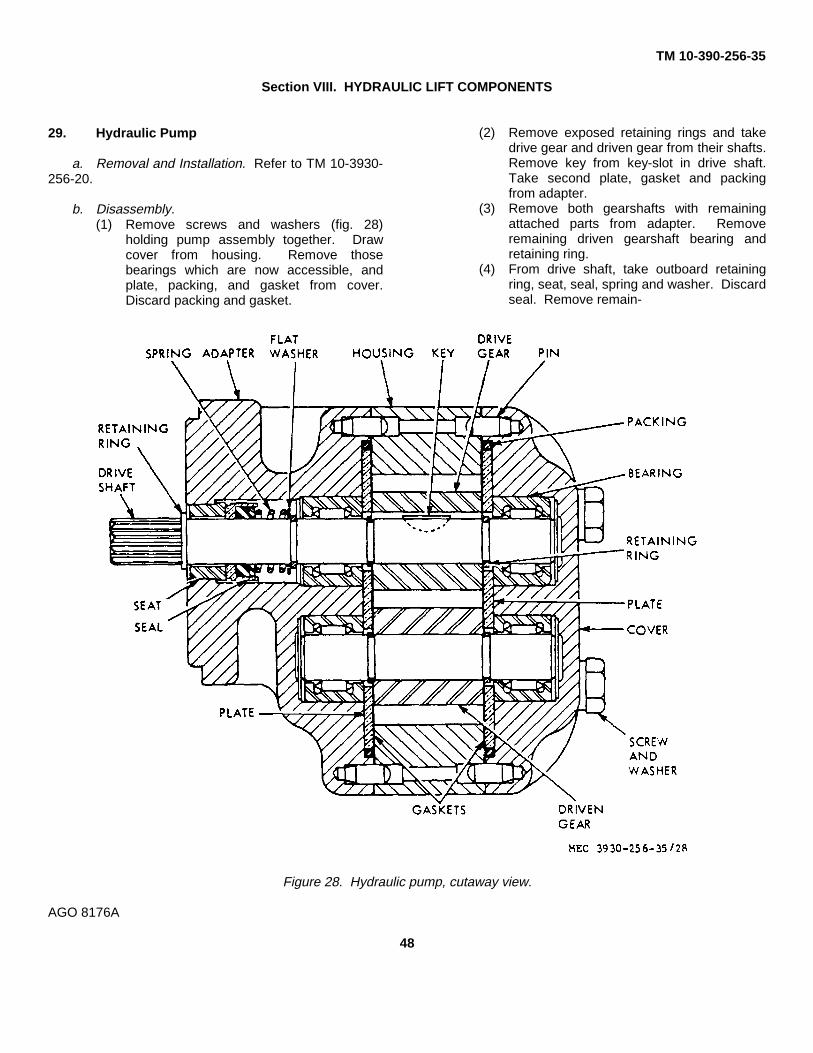
TM 10-390-256-35
Section VIII. HYDRAULIC LIFT COMPONENTS
29. Hydraulic Pump
a. Removal and Installation. Refer to TM 10-3930-256-20.
b. Disassembly.(1) Remove screws and washers (fig. 28)
holding pump assembly together. Drawcover from housing. Remove thosebearings which are now accessible, andplate, packing, and gasket from cover.Discard packing and gasket.
(2) Remove exposed retaining rings and takedrive gear and driven gear from their shafts.Remove key from key-slot in drive shaft.Take second plate, gasket and packingfrom adapter.
(3) Remove both gearshafts with remainingattached parts from adapter. Removeremaining driven gearshaft bearing andretaining ring.
(4) From drive shaft, take outboard retainingring, seat, seal, spring and washer. Discardseal. Remove remain-
Figure 28. Hydraulic pump, cutaway view.
AGO 8176A
48
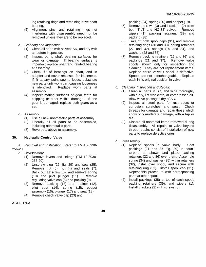
TM 10-390-256-35
ing retaining rings and remaining drive shaftbearing.
(5) Alignment pins, and retaining rings notinterfering with disassembly need not beremoved unless they are to be replaced.
c. Cleaning and Inspection.(1) Clean all parts with solvent SD, and dry with
air before inspection.(2) Inspect pump shaft bearing surfaces for
wear or damage. If bearing surface isimperfect replace shaft and related bearingat assembly.
(3) Check fit of beatings on shaft, and inadapter and cover recesses for looseness.If fit at any point seems loose, substitutenew parts until worn part causing loosenessis identified. Replace worn parts atassembly.
(4) Inspect mating surfaces of gear teeth forchipping or other visible damage. If onegear is damaged, replace both gears as aset.
d. Assembly.(1) Use all new nonmetallic parts at assembly.(2) Liberally oil all parts to be assembled,
including nonmetallic parts.(3) Reverse b above to assembly.
30. Hydraulic Control Valve
a. Removal and Installation. Refer to TM 10-3930-256-20.
b. Disassembly.(1) Remove levers and linkage (TM 10-3930-
256-20).(2) Unscrew plug (26, fig. 29) and seal (25).
Remove nut (5), nut (4) and seals (7).Back out setscrew (6), and remove spring(10) and pilot plunger (11). Removeregulating valve cap (8) and packing (9).
(3) Remove packing (13) and retainer (12),pilot seat (14), spring (15), poppetassembly (16), plunger (17) and seat (18).
(4) Remove check valve cap (23) and
packing (24), spring (20) and poppet (19).(5) Remove screws (3) and brackets (2) from
both TILT and HOIST valves. Removewipers (1), packing retainers (39) andpacking (38).
(6) Take off both spool caps (31), and removeretaining rings (30 and 33), spring retainers(27 and 32), springs (29 and 34), andwashers (28 and 35).
(7) Remove packing retainers (22 and 36) andpackings (21 and 37). Remove valvespools shown only for inspection andcleaning. They are not replacement items.Replace entire valve if spool is defective.Spools are not interchangeable. Replaceeach in its original position in valve.
c. Cleaning, Inspection and Repair.(1) Clean all parts in SD, and wipe thoroughly
with a dry, lint-free cloth, or compressed air.Blow valve passages dry of SD.
(2) Inspect all steel parts for rust spots orcorrosion, scratches, and wear. Checkthreads for damage and repair those whichshow only moderate damage, with a tap ordie.
(3) Discard all nonmetal items removed duringdisassembly. All repairs to valve beyondthread repairs consist of installation of newparts to replace defective ones.
d. Reassembly.(1) Replace spools in valve body. Seat
packings (21 and 37, fig. 29) in coun-terbore as shown and place packingretainers (22 and 36) over them. Assemblespring (34) and washer (35) within retainers(32), install over spool, and secure withretaining ring (33). Install spool cap (31).Repeat this procedure with correspondingparts at other spool.
(2) Install packings (38) at top of each spool,packing retainers (39), and wipers (1).Install brackets (2) with screws (3).
AGO 8176A
49

TM 10-390-256-35
1 Wiper 11 Pilot plunger 21 Packing 31 Spool cap2 Bracket 12 Retainer 22 Packing retainer 32 Spring retainer3 Screw 13 Packing 23 Check valve cap 33 Retaining ring4 Nut 14 Pilot seat 24 Packing 34 Spring5 Nut 15 Spring 25 Seal 35 Washer6 Setscrew 16 Poppet assembly 26 Plug 36 Packing retainer7 Seal 17 Plunger 27 Spring retainer 37 Packing8 Regulating valve cap 18 Plunger seat 28 Washer 38 Packing9 Packing 19 Check valve poppet 29 Spring 39 Packing retainer
10 Spring 20 Spring 30 Retaining ring
Figure 29. Hydraulic control valve, cutaway view.
AGO 8176A
50

TM 10-390-256-35
(3) Place packing (24) on check valve cap (23).Install poppet (19), spring (20) and cap andpacking.
(4) Press plunger seat (18) into position, installplunger (17) and poppet assembly (16),spring (15), and pilot seat (14). Put packing(13) on retainer (12) and install retainer.
(5) Position pilot plunger (11), and spring (10).Put packing (9) on cap (8) and install cap.
(6) Install setscrew (6), seals (7) and nut (4).Install nut (5), and install handles andlinkage by reversing a above.
e. Adjustment.(1) With valve installed on truck, and all hoses
connected, disconnect LIFT hose at valve.(2) At valve LIFT port, install a hydraulic
pressure gage calibrated to test 0 to 3000psi.
(3) Operate LIFT control handle to operateregulator valve. Note gage reading. Valvemust relieve at 1750 to 1850 psi. To adjust,remove nut (5), loosen nut (4), and turnsetscrew (6) clock-wise to raise setting orcounterclock-wise to lower setting. Tightenlocknut and replace cap nut (5), removegage and replace LIFT hose.
f. Installation. Reverse procedure in b above.
31. Hydraulic Tilt Cylinders
a. Removal and Installation. (TM 10-3930-25620).
b. Repair. Repair of tilt cylinders is accomplishedby installation of new parts to replace defective itemsfound during disassembly.
c. Disassembly.(1) Remove nut (1, fig. 30), washer (2) and
screw (13). Remove rod end (14) frompiston and rod (11).
(2) Remove screw (3), washer (4) and retainer(6). Remove wiper ring (5) and packing (7).Unscrew stuffing box (8) from cylinder (12),take out piston and rod (11), and removepackings (9 and 10) from piston.
d. Assembly.(1) Install packings (9 and 10, fig. 30) on piston
(11), and install in cylinder (12). Screwstuffing box (8) snugly into cylinder with apin spanner wrench.
(2) Position packing (7) in stuffing box andinstall packing retainer (6) with screws (3)and washers (4) only tightly enough toprevent seepage of fluid. This item can befurther tightened later after installation ofthe cylinder if necessary to stop leakage.
(3) Install wiper ring (5) on piston rod, replacerod end (14), screw (13), washer (2) andnut (1).
32. Lift Cylinder (130 Inch Lift)
a. Removal.(1) Drain hydraulic system oil (LO 10-3930-
256-20).(2) Disconnect cylinder hydraulic line, and
adapter (42, fig. 31) from regulator valve(41).
(3) Remove chain assemblies (TM 10-3930-256-20) from crosshead.
(4) Remove nut (1) from top of lift cylinder (46).Raise and brace inner upright (52) to clearlift cylinder and remove cylinder from truck.
b. Disassembly.(1) Clamp lift cylinder in vise equipped with V-
shaped jaws. Remove screws (1, fig. 32)and washers (2). Unscrew packing nut (7)from primary plunger (28). Remove wiperring .(6), packing (4) and packing assembly(9).
(2) Unscrew packing nut (11) from cylinder(27). Remove ring (10) and packingretainer (12) and packing assembly (26).
(3) Slide plunger (28) from primary cylinder(27) and remove guide (14) and retainingring (13).
(4) Unscrew packing nut (18) from cylinder(25). Remove ring (17), packing retainer(19), and packing assembly (20). Slidecylinder from plunger (24). Removebearing (21) from cylinder.
AGO 8176A
51

TM 10-390-256-35
(5) Remove packing (16) and washer (15) fromcylinder. Unscrew cylinder end (3) andremove packing (4), washer (5) and plunger(24). Remove bearings (21 and 23).
c. Cleaning, Inspection and Repair.(1) Clean all metal parts with SD.(2) Inspect all tubular sections for dents or
bends. Check all friction surfaces forroughness, pits or other irregularities.Discard all nonmetal parts.
(3) Repair moderate damage to threadedholes, with a tap. Remove minorroughness on friction surfaces by honing,followed by thorough recleaning to removetraces of abrasive.
d. Assembly.(1) Install bearings (21 and 23, fig. 32) on
secondary plunger (24).(2) Install secondary plunger in secondary
cylinder (25), place packing (4) and washer(5) on end of cylinder and install cylinderend (3). Install bleeder screw (1) andwasher (2) in cylinder, end.
(3) Install packing (16) and washer (15) ingroove on secondary cylinder. Replacepacking assembly (20), retainer (19),packing nut (18) and wiper ring (17).
(4) Install plunger guide (14) and retaining ring(13) in bore of primary plunger (28). Installitems assembled in (1) to (3) above inprimary plunger, then install primarycylinder over this assembly, and screwsecondary cylinder into primary cylinder.
(5) Install bleeder screw (1) and washer (2) inprimary cylinder. Install wiper ring (10) inpacking nut (11), and install packingassembly (26), packing retainer (12) andretain with packing nut (11).
(6) Install packing assembly (9), retainer (8)and nut (7).
e. Installation. Reverse the procedure in a above.Bleed air from cylinder by removing both bleeder screws(1, fig. 32), from cylinder,
and pressurizing cylinder until oil appears at the bleedholes. Replace screws after bleeding cylinders.
33. Crosshead Assembly (130 Inch Lift)
a. Removal.(1) Remove lift chains (TM 103930-256-20).(2) Remove nut (1, fig. 31). Raise inner upright
(52) to clear lift cylinder (46) and lift offcrosshead (52) assembly.
b. Disassembly. Remove retaining rings (47, fig.31), washers (48), bearings (49), and rollers (50).
c. Assembly. Pack bearings and rollers with GAA,and reverse b above.
d. Installation. Reverse a above.
34. Inner Upright Assembly (130 Inch Lift)
a. Removal.(1) Remove nut (1, fig. 31).(2) Remove screws (25), spacers (21), and
lock washers (24) attaching latchassemblies within carriage; remove latchassemblies. Raise and block up innerupright.
(3) Slide roller assemblies from lift carriage (7).Remove rollers (12) and bearings (10).Slide washers (11) and shims (9) fromcarriage. Disconnect lift chains fromcarriage and remove carriage.
(4) Remove screws (3) and lowering plates (2).(5) Remove screws (35) attaching inserts (38)
to outer upright (26); remove inserts.(6) Remove screws (30) and lockwashers (31)
attaching strikers (32). Remove strikersand spacers (33).
(7) Slide inner upright (52) up, and out of outerupright (26).
b. Installation. Pack bearings (10, fig. 31) withGAA, and liberally apply GAA to the sliding surfaces ofinner and outer uprights, then reverse a above.
AGO 8176A
52

TM 10-390-256-35
1 Nut 3 Screw 5 Wiper ring 7 Packing 9 Packing 11 Piston and rod 13 Screw2 Washer 4 Washer 6 Packing retainer 8 Stuffing box 10 Packing 12 Cylinder 14 Rod end
AGO 8176A
Figure 30. Tilt cylinder, exploded view.
53

TM 10-390-256-35
35. Lift Cylinder (172 Inch Lift)
a. Removal(1) Remove lift chains (TM 10-3930-25-20).(2) Disconnect hydraulic hose from flow
restrictor (44, fig. 33) at base of lift cylinder.Cap hose to keep out dirt.
(3) Remove screws (20), washers (19), bracket(18), nut (17), tube (16) and pulldown rod(1).
(4) Remove screws and washers which attachcrosshead to lift cylinder (fig. 33). Raisecrosshead free of cylinder.
(5) Remove cylinder from position in bottommember of outer upright and remove flowregulator and both elbows from base ofcylinder.
b. Disassembly.(1) Remove wiper ring, packing retainer,
packing set and sleeve bushing (fig. 34)from lift cylinder.
(2) If leakage is apparent, remove screw andgasket.
c. Assembly. Reverse b above, tightening packingretainer just snugly enough to prevent leakage.
d. Installation.(1) Reverse a above.(2) Loosen screw (fig. 34) enough to release
trapped air slowly, and operate lift cylinderuntil hydraulic fluid free of air bubbles leaksfrom around screw.
(3) Tighten screw and test operation of
1 Nut 19 Washer 37 Setscrew2 Lowering plate 20 Screw 38 Outer upright insert3 Screw 21 Spacers 39 Ball4 Load backrest 22 Screw 40 Pipe nipple5 Spacer 23 Plate 41 Elbow and flow restrictor6 Fork support shaft 24 Washer 42 Fitting7 Lift carnage 25 Screw 43 Nuts8 Shim 26 Outer upright 44 Chain adjustment screw9 Shim 27 Angle bracket 45 Chains
10 Bearings 28 Washer 46 Lift cylinder11 Retaining ring 29 Screw 47 Retaining ring12 Roller 30 Screw 48 Washer13 Pin 31 Washer 49 Roller bearing14 Bolt 32 Striker latch 50 Bearing roller15 Shim 33 Spacer 51 Crosshead16 Spring 34 Insert shim 52 Inner upright17 Forks 35 Screw18 Shaft lock plate 36 Headless screw
Figure 31. Mast assembly (130 inch lift), exploded view.
AGO 8176A
54

TM 10-390-256-35
Figure 31. Mast assembly (130 inch lift), exploded view-Continued.
AGO 8176A
55
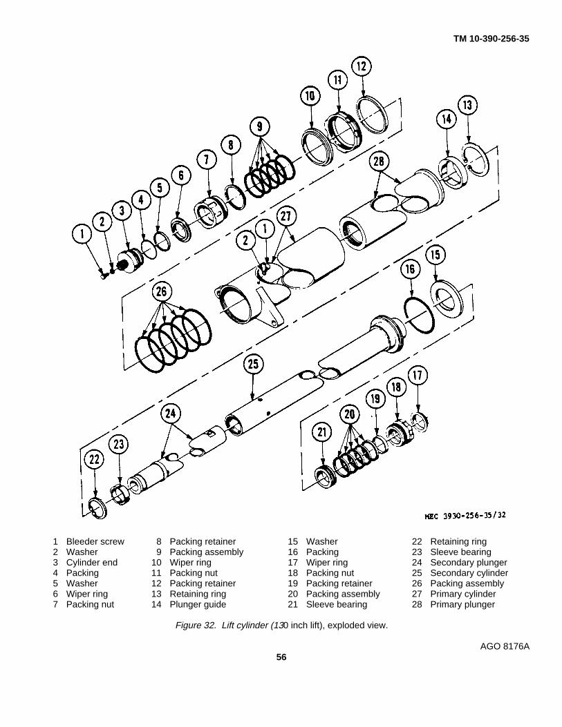
TM 10-390-256-35
1 Bleeder screw 8 Packing retainer 15 Washer 22 Retaining ring2 Washer 9 Packing assembly 16 Packing 23 Sleeve bearing3 Cylinder end 10 Wiper ring 17 Wiper ring 24 Secondary plunger4 Packing 11 Packing nut 18 Packing nut 25 Secondary cylinder5 Washer 12 Packing retainer 19 Packing retainer 26 Packing assembly6 Wiper ring 13 Retaining ring 20 Packing assembly 27 Primary cylinder7 Packing nut 14 Plunger guide 21 Sleeve bearing 28 Primary plunger
Figure 32. Lift cylinder (130 inch lift), exploded view.
AGO 8176A56

TM 10-390-256-35
cylinder. If fluid leaks around packing,tighten packing retainer only enough to stopleak.
36. Crosshead, Inner Upright, and CarriageAssembly
a. Removal. Refer to paragraph 13a(1).
b. Disassembly.(1) Remove chains (TM 10-3930-256-20).(2) Remove lift cylinder (para. 35a).(3) Lift off load back rest (21, fig. 33).(4) Raise inner upright (12) slightly, loosen nut
(17) at bottom of guide rod (1) andunscrew rod from bracket (18) on innerupright. Remove rod, tube (16), nut, andbushing within crosshead (48). Liftcrosshead from cylinder.
(5) Refer to paragraph 33 for completecrosshead service instructions.
(6) Remove screws (20, fig. 33) and washers(19) attaching bracket (18) to inner upright(12) and remove bracket.
(7) Remove screws (32), washers (33), andcarriage bar (31) from carriage (23).Remove forks (36). Lift carriage out ofinner upright.
(8) Remove roller assemblies (30) and shims(29) from carriage trunnions.
(9) Remove plugs (10) and setscrews
(11), and remove inner upright from withinouter upright (42).
c. Repair.(1) Repair damaged threaded items by
cleaning up threads with a tap or die.(2) Straighten slightly deformed structural items
by cold bending.(3) Replace any damaged elements not readily
repaired by procedures in (1) or (2) above.
d. Assembly.(1) Reverse procedures in b above.(2) Bleed air from lift cylinder (para. 35d (2)).
37. Hydraulic Oil Tank
a. Removal.(1) Raise truck high enough to clear oil tank at
removal, and provide access to attachingparts.
(2) Drain oil from tank (LO 10-3930-256-20).(3) Loosen hose clamp (fig. 35) and disconnect
hose between tank and filter.(4) Disconnect pump suction line at tank (refer
to Suction Filter Cartridge Replacement inTM 10-3930-256-20).
(5) Remove screws and washers (fig. 35), andtake tank from truck.
b. Installation. Reverse a above, and fill tank withoil as instructed in LO 10-3930-256-20.
AGO 8176A
57

TM 10-390-256-35
Figure 33. Mast assembly (172 inch lift), exploded view.
AGO 8176A
58

TM 10-390-256-35
1 Upright guide rod 26 Washer2 Screw 27 Screw3 Lever setscrew 28 Setscrew4 Sleeve bushing 29 Retaining ring5 Spring 30 Bearing and roller6 Right hand upright lever 31 Fork shaft lock plate7 Left hand upright lever 32 Screw8 Spring pin 33 Washer9 Straight shaft 34 Chain anchor
10 Headless screw 35 Nut11 Setscrew 36 Forks12 Inner upright 37 Screw13 Upright lever hook 38 Washer14 Cotter pin 39 Plate15 Shaft 40 Angle’ bracket16 Tube 41 Screw and washer17 Nut 42 Outer upright18 Pulldown rod bracket 43 Elbow19 Washers 44 Flow restrictor20 Screw 45 45° angle fitting21 Load backrest 46 Adapter bushing22 Fork shaft 47 Lift cylinder23 Lift carriage 48 Crosshead assembly24 Fork spacer 49 Washer25 Carriage spacer bar
Figure 33. Mast assembly (172 inch lift), exploded view-Continued.
Figure 34. Lift cylinder (172 inch lift), exploded view.AGO 8176A
59

TM 10-390-256-35
Figure 35. Oil tank removal.
Section IX. ELECTRIC MOTORS
38. General
The three motors on the truck are series wound dcmotors. The travel motor and hydraulic pump motor aresimilar, except for size, and provision for parking brakemounting and rotation reversal on the travel motor. Thefollowing general procedures apply to all three motors.They will not be repeated subsequently.
a. Inspection.(1) With motor on test operation for five
minutes, observe for bearing heating,
unusual noises from bearings or brushes,and vibration.
(2) Observe action of brushes on commutator.Excessive sparking of brushes indicatesworn brushes, weak brush springs,defective armature or commutator.
(3) Note length of brushes at inspection bycomparison with new replacement brush.Replace any brush worn to less than halfthe length of new brush.
1 Bearing retainer 12 Insulator 23 Screw 34 Nut 45 Field coil2 Washer 13 Washer 24 Fan 35 Washer 46 Nut3 Bearing 14 Electrical lead 25 Shield 36 Screw 47 Washer4 Pole piece screw 15 Brush holder 26 Washer 37 Insulator 48 Washer5 Frame 16 Insulator 27 Nut 38 Washer 49 Drive end bell6 Insulator 17 Terminal nut 28 Screw 39 Washer 50 Washer7 Washer 18 Washer 29 Screw 40 Screw 51 Screw8 Screw 19 Washer 30 Washer 41 Brush spring 52 Washer9 Armature 20 Washer 31 Dust seal 42 Brush 53 Screw
10 Screw 21 Screw 32 Brush end bell 43 Pole piece11 Washer 22 Cover 33 Washer 44 Insulator
Figure 36. Travel motor, exploded view.
AGO 8176A
60

TM 10-390-256-35
Figure 36. Travel motor, exploded view-Continued
AGO 8176A
61

TM 10-390-256-35
(4) Inspect interior of motors and brushinspection covers for thrown solder,indicating overheating in operation.
b. Cleaning.(1) Before disassembly, wipe exterior with a
cloth moistened with SD.(2) Remove as much dirt as practical from
parts with compressed air.(3) Wipe remaining dirt from parts with a cloth
slightly moistened with SD. Do not wetarmature or field windings.
(4) Clean commutators to bright finish with 00or finer sandpaper, or commutator stone.Do not use emery cloth.
c. Lubrication. Lubricate unsealed bearings withgrease, GAA. Do not try to lubricate sealed bearings.
d. Repair. Repair of all motors is limited tosoldering loose solder joint connections, truingcommutators, in a lathe, and replacing defective parts.
e. Run-in. Run-in new brushes with motorsunloaded, at 12 to 16 volts dc only. Higher voltage couldcause overspeeding, and armature destruction.
39. Travel Motor
a. Removal. Refer to paragraph 13a.
b. Installation.(1) Perform paragraph 15d, (2) and (3).(2) Reverse a above.
c. Disassembly. Disassemble only as far asnecessary to repair, as follows:
(1) Remove screws (36 and 23, figure 36),washers (33 and 35), nuts (34), and take offcovers (22).
(2) Disconnect leads (14) at brush holders(15). Remove brushes (42) from
motor. Unscrew fan (24) from shaft ofarmature (9).
(3) Remove screws (53) and washers (52).Take off end bell (49). Remove screws(53), washers (52), bearing retainer (1),washer (2) and bearing (3).
(4) Remove socket head screws (21) andseparate frame (5), armature (9) and endbell (32). Take nut (17), washers (13, 18,and 19), insulator (12) and leads (41) fromend bell.
(5) Remove screws (4) to free pole pieces (43),insulators (44) and field coils (45).
d. Inspection, Cleaning, Lubrication and Repair.Refer to paragraph 38, for general instructions.Additionally,
(1) If balancing machine is available, checkarmature dynamic balance to be within 1inch ounce, at 3000 revolutions per minute.
(2) Measure commutator run out. If in excessof 0.002 inch total indicator reading, turn inlathe, truing commutator within above limits,and holding copper surface smoothness toless than 33 microinches. This finish maybe obtained, after lathe turning, with finesandpaper or commutator stone.
(3) Check brush length of used brushes bycomparing them with new brush. If brusheshave less than 2/3 length of new brushes,replace them, as they will not last until nextregular disassembly.
e. Assembly. Reverse c above.
f. Test After Assembly.(1) Separately excite the field with rated current
(100 amps), making terminal S1 positiveand terminal S2 negative.
1 Commutator end bell 8 Insulator 15 End bell 22 Screw2 Brush spring 9 Insulator 16 Bolt 23 Bearing3 Brush 10 Washers 17 Washer 24 Screw and washer4 Screw 11 Nuts 18 Field winding 25 Spacer yoke and brush holders5 Brush access cover 12 Armature 19 Pole piece 26 Bolt and washer6 Terminal screw 13 Woodruff key 20 Screw7 Washer 14 Bearing 21 Field frame
Figure 37. Hydraulic pump motor, exploded view.
AGO 8176A
62

TM 10-390-256-35
Figure 37. Hydraulic pump motor, exploded view-Continued.
AGO 8176A
63

TM 10-390-256-35
(2) Seat brushes, and run motor with ratedvoltage on armature terminals, making A2positive and A1 negative. Armature mustnow turn clockwise, viewed fromcommutator end.
(3) After brushes have been seated and motorhas run for four minutes, record speed,armature current and voltage, and fieldcurrent. Observe commutator and brushesfor sparking at this time.
(4) Make a high potential test above ground onall windings, using 600 volts ac for onesecond, or 500 volts ac for one minute.
40. Hydraulic Pump Motor
a. Removal and Installation. Refer to TM 10-3930-256-20.
b. Disassembly. Disassemble only as far asnecessary, as follows:
(1) Remove screw (22, fig. 37), and brushaccess cover (5). Press down on eachbrush spring (2) to unhook it at the bottom,and remove brush springs. Removescrews (4) and brushes (3).
(2) Remove screws and washers (26) and takeoff end bell (1) with spacer yoke (25).Remove screws and washers (24), andyoke.
(3) Remove armature (12), and bearings (14and 23).
(4) Remove screws (16), washers (17), andtake end bell (15) from field frame (21).
(5) Remove nuts (11), washers (7 and 10),insulators (8), and terminal screws (6) fromfield frame.
(6) Remove screws (20), pole piece (19), andfield windings (18).
c. Inspection.(1) Refer to paragraph 38a.(2) With motor assembled, check that
brush spring tension is between 26 and 32ounces.
d. Cleaning. Refer to paragraph 38b.
e. Assembly. Reverse b above.
f. Test After Assembly.(1) Refer to TM 10-3930-256-20.(2) Make a test connection to a brush holder 90
mechanical degrees from the brush holderconnected to terminal A1.
(3) From an independent source separatelyexcite the series field at 57.5 amperes,making test connection positive, and S2negative.
(4) From a separate independent power sourceapply rated voltage to armature, making A1positive and test connection negative. Seatbrushes and run motor. Rotation should beclockwise, viewed from commutator end.
(5) Make a high potential test above ground onall windings, using 600 volts ac for onesecond, or 500 volts ac for one minute.
41. Steering Motor
a. Removal and Installation. Refer to TM 10- 3930-256-20.
b. Disassembly. Disassemble only as far asnecessary, as follows:
(1) Remove screw (1, fig. 38) and fan guard(2). Remove setscrew (3) and take fan (4)from motor. Relieve pressure of brushsprings (9) on brushes (10) and removebrushes.
Caution: Do not pull brushes out byleads, if brushes might be serviceable.Leads may be damaged.
(2) Remove screws from both end bells (7 and14). Take end bells from field frame (16).Remove armature (13) from field frame.
1 Screw 8 Brush frame 15 Bearing2 Fan guard 9 Brush springs 16 Frame3 Setscrew 10 Brushes 17 Field coils4 Fan 11 Washer 18 Lockwasher5 Bracket 12 Washer 19 Nut6 Bearing 13 Armature 20 Washer7 Brush end bell 14 Drive end bell 21 Screw
AGO 8176A
64

TM 10-390-256-35
Figure 38. Steer pump motor, exploded view-Continued.
AGO 8176A
65

TM 10-390-256-35
Figure 39. Electrical equipment box, and wire labels.
AGO 8176A
66

TM 10-390-256-35
1 Nuts 6 Fuseholder 11 Nut 16 Fuse (14 a. rating)2 Washers 7 Screws 12 Lockwasher 17 Screw3 Fuse 8 Nut 13 Screw 18 Fuse4 Washer 9 Lockwasher 14 Bus bar 19 Fuse5 Screw 10 Flat washer 15 Fuseholder
Figure 40. Fuseholder assembly, exploded view.
(3) Remove screws (21), washers (20), andtake brush holder (8) from commutator endbell. If they are to be replaced, takebearings (6 and 15) from end bells.
c. Inspection. Refer to paragraph 38a.
d. Cleaning. Refer to paragraph 38b.
e. Repair. Refer to paragraph 38d.
f. Assembly. Reverse b above.
g. Test After Assembly. Refer to TM 10-3930-256-20.
42. Electrical Equipment Box Cover
a. Removal.(1) Remove truck cowl (TM 10-3930-256-20).(2) Remove cover screws (fig. 39) and cover.
b. Installation. Reverse a above.
AGO 8176A
67

TM 10-390-256-35
43. Relays
All relays are housed in the electrical equipment box(fig. 39). All are attached to the box with thread cuttingscrews and washers. Removal and installationprocedures for all relays are the same.
a. Removal.(1) Remove electrical equipment box cover
(par. 42a).(2) Disconnect electrical leads to relay.
Note. Disconnect only those leadswhich prevent removal of relay. Do notremove any conductor which is acomponent of a relay.
(3) Remove thread cutting screws andwashers, and take relay from electricalequipment box.
b. Installation. Referring to figure 39 for guidancein connecting leads, reverse a above. Circleddesignators on figure 39 correspond to circuitidentification labels on wires at terminals.
44. Fuseholder Assembly
Refer to figure 39 for location of fuseholderassembly.
a. Removal and Disassembly.(1) Remove electrical equipment box cover
(para. 42a).(2) Remove cover over fuses (TM 10-3930-
25620).(3) Disconnect leads from bus bar (14).(4) Remove nuts (11, fig. 40), washers (12),
and screw (13), and remove
fuseholder assembly from equipment box.(5) Remove nuts (8), washers (9 and 10),
screws (17) and take fuseholder (15) forsmall fuses from larger fuseholder (6).
b. Assembly and Installation. Reverse a above.
45. Directional Switch
a. Removal and Installation. Refer to TM 10-3930-256-20.
b. Contact Replacement.(1) Remove screws (3, fig. 41), washers (4),
and cover (2).(2) Press contact fingers (8) together, rotate
them one-fourth turn, and take them fromcontact carrier (10).
(3) Remove screws holding terminal boards (5and 6). Remove terminal boards withcontacts.
(4) Install new contacts by reversing (1) to (3)above.
c. Switch Disassembly. Disassemble only as far asnecesary to repair, as follows:
(1) Perform steps (1) to (3) above.(2) Remove springs (19, fig. 41). Remove clips
and screws (15), hinge pins (16), and rollerarm assemblies (18).
(3) Remove screw (13) and washers (11 and12), then take operating shaft (17), bushing(9), and contact carrier (10) from housing(14).
d. Switch Assembly. Reverse c above.
1 Knob 8 Contact fingers 15 Retaining clip and screw2 Cover 9 Bushing 16 Hinge pin3 Screw 10 Contact carrier 17 Operating shaft4 Washer 11 Washer 18 Roller arm assembly5 Terminal board 12 Washer 19 Handle return springs6 Terminal board 13 Screw 20 Lever7 Contact spring 14 Housing 21 Screw
Figure 41. Directional switch, exploded view.
AGO 8176A
68
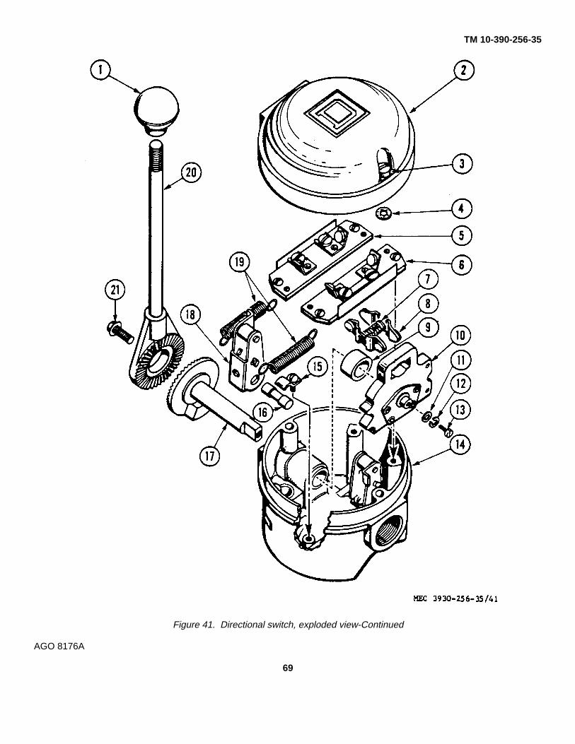
TM 10-390-256-35
Figure 41. Directional switch, exploded view-Continued
AGO 8176A
69

TM 10-390-256-35
APPENDIX IREFERENCES
AR 320-5-------------------------------- Dictionary of United States Army Terms.AR 320-50 ------------------------------ Authorized Abbreviations and Brevity Codes.AR 700-3900-5 ------------------------ Registration of Materials Handling Equipment and Special Purpose Vehicles.AR 700-58 ------------------------------ Report of Damaged or Improper Shipment.AR 746-5-------------------------------- Color and Marking of Materiel.AR 750-3900-1 ------------------------ Materials Handling Equipment.AR 750-5-------------------------------- Organization, Policies and Responsibilities for Maintenance Operation.DA Pam 108-1------------------------- Index of Army Motion Pictures, Film Strips, Slides, and Phono Recordings.DA Pam 310-1------------------------- Military Publications: Index of Administrative Publications.DA Pam 310-2------------------------- Military Publications: Index of Blank Forms.DA Pam 310-3------------------------- Military Publications: Index of Training Publications.DA Pam 310-4------------------------- Military Publications: Index of Technical Manuals, Technical Bulletins.
Supply Manuals (types 4, 6, 7, 8, and 9), Supply Catalogs (type CL),Supply Bulletins, Lubrication Orders, and Modification Work Orders.
FM 21-30 ------------------------------- Military Symbols.FM 21-5 --------------------------------- Military Training Management.FM 21-6 --------------------------------- Techniques of Military Instruction.LO 10-3930-256-20 ------------------ Lubrication Order; Truck, Lift, Fork, Electric, Solid Rubber Tired
Wheels, 6000 Pound Capacity, Army Model MHE-198, Baker ModelFTD-060-EE, Federal Stock Number 3930-724-4057 (130 in. lift),Federal Stock Number 3930-724-4059 (172 in. lift).
MIL-STD-162A ------------------------ Preparation for Delivery of Warehouse Materials Handling Equipmentfor Domestic and Oversea Shipment and Storage.
SB 5-111-------------------------------- Supply of DA Approved Fire Extinguishers to Army Troop Users.TM 9-213 ------------------------------- Painting Instructions for Field Use.TM 10-3930-256-10 ------------------ Operator’s Manual; Truck, Lift, Fork, Electric, Solid Rubber Tired
Wheels, 6000 Pound Capacity, Army Model MHE-198, Baker ModelFTD-060-EE, Federal Stock Number 3930-724-4057 (130 in. lift),Federal Stock Number 3930-724-4059 (172 in. lift).
TM 10-3930-256-20 ------------------ Organizational Maintenance Manual; Truck, Lift, Fork, Electric, SolidRubber Tired Wheels, 6000 Pound Capacity, Army Model MHE-198,Baker Model FTD-060-EE, Federal Stock Number 3930-724-4057 (130in. lift), Federal Stock Number 3930-724-4059 (172 in. lift).
TM 10-3930-256-20P ---------------- Organizational Maintenance Repair Parts and Special Tools List; Truck,Lift, Fork, Electric, Solid Rubber Tired Wheels, 6000 Pound Capacity.Army Model MHE-198, Baker Model FTD-060-EE, Federal StockNumber 3930-724-4057 (130 in. lift), Federal Stock Number 3930-724-4059 (172 in. lift).
AGO 8176A
70
TM 10-390-256-35
TM 10-3930-256-35P ---------------- Direct and General Support and Depot Maintenance Repair Parts and SpecialTools List: Truck, Lift, Fork, Electric, Solid Rubber Tired Wheels, 6000 PoundCapacity, Army Model MHE-198, Bakrd Model FTD-060-EE, Federal StockNumber 3930-724-4057 (130 in. lift) Federal Stock Number 3930-724-4059(172 in. lift).
TM 21-300------------------------------ Driver Selection and Training (Wheeled Vehicles).TM 38-230------------------------------ Preservation, Packaging, and Packing of Military Supplies and Equipment.TM 38-750------------------------------ Army Equipment Records Procedures.TM 5-764 ------------------------------- Electric Motor and Generator Repair.TM 10-1690A -------------------------- Industrial Motive Power Storage Batteries for Materials Handling Equipment.
AGO 8176A
71

TM 10-390-256-35
APPENDIX II
MAINTENANCE ALLOCATION
Maintenance Allocation Chart is published in TM 10-3930-256-20.
AGO 8176A
72

TM 10-390-256-35
APPENDIX III
REPAIR PARTS AND SPECIAL TOOL LISTS
Repair parts and special tool lists is published in TM 10-3930-25-35P.
AGO 8176A
73

TM 10-390-256-35
APPENDIX IV
DIRECT AND GENERAL SUPPORT MAINTENANCE SUPPORT OF ORGANIZATIONAL LEVEL SERVICE ONRECEIPT OF NEW EQUIPMENT (TM 10-3930-256-20)
On receipt of a new truck, the using organization will require the assistance of maintenance facilities with weldingcapability, for initial installation of battery retaining parts shipped loose with truck. Refer to Basic Issue Item Lists in TM 10-3939-25610 for part numbers of these parts. Locate two angles to suit dimensions of battery installed. Weld andassemble parts as shown in figure 42.
Figure 42. Installation drawing, battery retaining parts.
AGO 8176A
74

By Order of the Secretary of the Army:
HAROLD K. JOHNSON,General, United States Army,
Official: Chief of Staff.J. C. LAMBERT,Major General, United States Army,The Adjutant General.
Distribution:
Active Army:USASA (1) Armies (5)DCSLOG (1) Instl (2)CNGB (1) USMA (1)CAR (1) Br Svc Sch (2) exceptCofEngrs (6) USAQMS (10)CofSptS (1) Army Dep (4)Dir of Trans (1) NLABS (4)CC-E (1) USA Mob Equip Cen (46)USCONARC (2) USAQMTC (4)USAMC (12) Mob Equip Manuals Fld Ofc (Ft Lee) (2)ARADCOM (2) POE (2)ARADOM Rgn (2) USA Tml Comd (2)OS Maj Comd (3) Army Tml (2)LOGCOMD (1) Arsenals (2)USAMOCOM (2) PG (2)USAWECOM (5) QM Fld Maint Shops (2)USAMICOM (5) Units org under fol TOE:USAMUCOM (5) 8-187 (2)USAECOM (5) 9-367 (2)USATECOM (5) 10-337 (2)USASMC (1) 10-407 (2)MDW (1) 10-467 (2)
NG: State AG (3).USAR: None.For explanation of abbreviations used, see AR :320-50.
*U.S. GOVERNMENT PRINTING OFFICE: 1975-579-377/365U.S. ARMY ADJUTANT GENERAL PUBLICATIONS CENTER, ST. LOUIS, MO, 1995
AGO 8176A
75


PIN: 028504

This fine document...
Was brought to you by me:
Liberated Manuals -- free army and government manuals
Why do I do it? I am tired of sleazy CD-ROM sellers, who take publicly available information, slap “watermarks” and other junk on it, and sell it. Those masters of search engine manipulation make sure that their sites that sell free information, come up first in search engines. They did not create it... They did not even scan it... Why should they get your money? Why are not letting you give those free manuals to your friends?
I am setting this document FREE. This document was made by the US Government and is NOT protected by Copyright. Feel free to share, republish, sell and so on.
I am not asking you for donations, fees or handouts. If you can, please provide a link to liberatedmanuals.com, so that free manuals come up first in search engines:
<A HREF=http://www.liberatedmanuals.com/>Free Military and Government Manuals</A>
– SincerelyIgor Chudovhttp://igor.chudov.com/
– Chicago Machinery Movers