TLP Issue 7 September/October 14
56
THE LOGISTICS PORTAL MAGAZINE TLP INSIGHT Issue 7 - 2014 THE LOGISTICS PORTAL MAGAZINE AIR CARGO - RFID - TEMPERATURE CONTROL - CLINICAL - BIO PHARMA - LOGISTICS TLP Insight: a journal for the life science logistics industry KEEP YOUR THE ULTIMATE GUIDE TO EFFECTIVE TEMPERATURE CONTROL IN REFRIGERATED TRANSPORT COOL
-
Upload
tlp-insight -
Category
Documents
-
view
221 -
download
3
description
TLP Issue 7
Transcript of TLP Issue 7 September/October 14

THE LOGISTICS PORTAL MAGAZINE
TLPINSIGHTIssue 7 - 2014
THE LOGISTICS PORTAL MAGAZINE
AIR CARGO - RFID - TEMPERATURE CONTROL - CLINICAL - BIO PHARMA - LOGISTICS
TLP Insight: a journal for the life science logistics industry
KEEP YOUR
THE ULTIMATE GUIDE TO EFFECTIVE TEMPERATURE CONTROL
IN REFRIGERATED TRANSPORT
COOL


THE LOGISTICS PORTAL MAGAZINE
MANAGING DIRECTORLee Atkinson
MANAGING EDITORBridget Langston
CONSULTANT EDITORTony Wright
SENIOR DESIGNERJoey Graham [email protected]
EDITORIAL ASSISTANTSNicholas RidgmanJamie Ward
CIRCULATION MANAGERTony Williams
SALESRakesh Makwana, Lee Atkinson, Amy Firth
ADMINISTRATIONKatie Galelli
WEBSITE DESIGNKnut Henriksen
CONTACT USSales:[email protected]
Subscription:[email protected]
TLP INSIGHTIs published 4 times a year March, June, September & December by Intensive Media Ltd. Printed by Premier Print & Direct Mail Group.Send address changes to:145 - 157 St Johns StreetLondonEC1V 4PWUnited Kingdom
The opinions and views expressed by the authors in this book are not necessarily those of the Editor or the Publisher and, whilst every care has been taken in the preparation and design of this book, the Editor nor the Publisher are not responsible for such opinions and views, or for any inaccuracies in the articles.Whilst every care is taken with artwork supplied, the Publisher cannot be held responsible for any loss or damage incurred, The entire content of this publication is protected by copyright. No part of this publication may be reproduced, stored in a retrieval system or transmitted in any form, by any means – electronic, mechanical, photocopying or otherwise – without prior permission of the Publisher.
Copyright© 2013 Intensive Media Ltd
TLPINSIGHT//MAIN CONTENT
Rachel Griffiths is Associate Director of Operations at Biotec Services International, where she
has responsibility for the warehouse, production and project management. Here she shares
her wide range of experience with us regarding the challenges clinical supplies companies face
when they need to establish warehousing systems that are flexible and affordable.
Contents continue on page 4 »
The challenges of warehousing for clinical supplies companies8
David Thorley, Global Refrigeration Specialist for Navman Wireless outlines in this guide the
general concepts of transport refrigeration systems plus current legislative requirements and
also explores ways in which temperature monitoring systems can be used in practice to help
improve temperature control and simultaneously drive down operating costs.
Keep your cool: The ultimate guide to effective temperature control in refrigerated transport
13
FEATURED ARTICLE

TLPINSIGHT www.the-logistics-portal.com4.
THE LOGISTICS PORTAL MAGAZINE
WWW.THE-LOGISTICS-PORTAL.COM Issue 07 - 2014TLP
//FEATUREDCONTENT
Authors Herman Teering, Managing Director and Panos Drougas MSc, Senior Chemical Consultant of DGM Software Development Group give us the
background, explanation and different answers to the question, ‘Who is responsible for the correct classification and labelling/marking (of hazards) of
substances and mixtures?’
The knowledge gap: classification and labelling/marking of dangerous goods
48
Anthony Bour of Thermo King provides us with a comparative study between Thermo King’s unique approach to temperature control and conventional diesel
systems, demonstrating how industry leader Thermo King is applying current and emerging technologies to help their customers achieve sustainable and
quiet transport refrigeration.
A sustainable solution for temperature controlled urban distribution
44
Brian Kohr is President and CEO of CSafe Global and in this September 2014 White Paper he looks at quality risk management in the distribution of
temperature-sensitive pharmaceuticals, where there is an increasing emphasis on shippers and manufacturers taking ultimate responsibility for examining
their supply chains using a ‘risk-based’ approach.
It’s a risky business42
a high technology smart boxFor highly secure shipping
STP is a division of Sofrigamwww.sustainablethermalpackaging.com

//FEATUREDCONTENTa high technology smart box
For highly secure shipping
STP is a division of Sofrigamwww.sustainablethermalpackaging.com

TLPINSIGHT www.the-logistics-portal.com6.
THE LOGISTICS PORTAL MAGAZINE
WWW.THE-LOGISTICS-PORTAL.COM Issue 07 - 2014TLP
//TLP INSIGHT FOREWORDSeptember 2014 and we are heading here at TLP Insight, towards the end of our second successful year of publication.
We are very pleased to have once again, a range of articles reflecting the challenges facing the life science logistics industry from
different perspectives.
From the world of clinical supplies companies, Rachel Griffiths, Associate Director of Operations at Biotec Services International,
gives us the benefit of her experience in her article about the provision of billable and commercially viable warehousing systems.
From the world of temperature control, specialist, David Thorley, from Navman Wireless gives us plenty to chew over in his
thorough and informative guide to effective temperature control in refrigerated transport. And Anthony Bour from Thermo King
provides a comparative study, which can assist companies with finding sustainable and quiet transport solutions when delivering
in urban areas.
Risky business is the order of the day for Brian Kohr, President and CEO of CSafe Global, giving us some timely information in
the current climate of increased regulatory activity in Risk Management.
And what can be riskier than the handling of dangerous goods? Herman Teering, Managing Director and Panos Drougas MSc,
Senior Chemical Consultant of DGM Software Development Group need do little to persuade us of the merits of finding answers
to the question of who has responsibility in the classification and labelling of hazardous substances!
In our very first issue we were very clear about our intentions – we set out to create a unique publication that would promote
understanding of the different problems different players in the market face – from technology and software to shipment and air
cargo and we are proud at TLP Insight to have been able to maintain that vision.
Lee Atkinson Managing Director
Intensive Media
THE LOGISTICS PORTAL MAGAZINE
For more information about this or any other Softbox Packaging System visit www.softboxsystems.comPatent GB2459392 “Transport Container” – International Patents Pending © 2012 Softbox Systems Ltd all rights reserved
EUROPE Softbox Systems Ltd.Units 1-2 RidgewayDrakes DriveLong Crendon Buckinghamshire HP18 9BFUKT: +44 1844 203 560F: +44 1844 203 570E: [email protected]
AMERICASSoftbox Systems Inc.1160 NW Elliot CourtBend, Oregon 97701USAT: +1 541 389 9183F: +1 888 610 0750E: [email protected]
INDIASoftbox Systems India Pvt Ltd.Survey No. 146-148, Village Ajivali, Kon, Old Pune Highway NH-4, Taluka Panvel, District Raigad, Maharashtra 410206T: +91 2232 222 380F: +91 2143 221 789E: [email protected]
ASIA PACIFICSoftbox Temperature Control Packaging Systems Pte. Ltd.48 Toh Guan Road East#02-115 Enterprise HubSingapore 608586T: +65 6316 9584F: +65 6316 9504E: [email protected]
• Cost effective protection of ambient products
• Innovative design uses only 6 components
• Insulated pallet shields product from hot tarmac
• Supplied with UV reflective waterproof cover
• Moulded insulation panels for “Glide Fit” assembly
• No coolant required – pack and ship in minutes
• Flat packs to reduce delivery, storage & return costs
• Manufactured from 100% recyclable materials
Reduce costs and maintain “Label Claim” temperature for shipping pharmaceuticals
1. Euro & US Pallet Versions2. UV reflective waterproof cover3. Five Euro systems on air pallet 4. Insulated Pallet Base
1
3
2
4
Protecting your pharmaceuticals whatever their destination
www.softboxsystems.com

TLPINSIGHT www.the-logistics-portal.com8.
volume of drug product. This drug may also have various
strengths and placebo and each vial of product could be
unlabelled and virtually identical to other strengths and the
placebo, particularly if it is to be used in a blinded trial. These
materials must be segregated and fully traceable. Placing them
all within a pallet location would be a cheap storage solution but
a major non-compliance in terms of GMP as the material would
not be sufficiently segregated and warehouse operators would be
picking different drug and placebo from the same location. Once
picked these materials are identical and the chance of mix up in
this situation is very high which could lead to catastrophic results
for the trial and place patient safety at severe risk.
For companies who have very large amounts of available
controlled temperature pallet storage space (e.g. at -20°C
and 2-8°C), they may be able to easily accommodate using six
pallet locations for half a pallet’s volume of material and offer
the storage at a low enough cost that the client can afford it.
However, there will come a time when they will run out of space
and either need to build additional storage space, which is costly
and may take a long period of time, or maximise the capacity from
the current warehouses. For other providers, particularly those
specialising in niche products, they may have limited controlled
temperature storage capacity and separate pallet locations for
each product is not an option.
A simple solution is to have a number of different size storage
locations. These could be provided by using variable size racking
options or by placing different sized boxes or bins within a pallet
location to subdivide the space. The product could then be placed
within its original packaging, into the bins for storage. Each bin
of warehousing for clinical supplies
companies.Rachel Griffiths
The
CHA ENGES
All clinical supplies companies must supply storage
and warehousing which will comply with Good
Manufacturing Practice (GMP) regulations. It must
maintain temperature, be fully monitored and
provide product segregation. However, for clinical
supplies companies which provide this storage as
a chargeable service to its clients, the storage and
warehousing must also be billable and commercially
viable.
Therefore companies need to establish warehousing
systems that are flexible and affordable. When clients
are paying for storage they do not want to pay for
‘air space’. Equally the storage providers do not want
to waste storage space by placing a small quantity of
product in a large location as this reduces the volume
of space available for use by other customers.
One way of achieving the balancing act between
what clients will pay vs. maximisation of warehouse
capacity is to use variable location sizes.
Location, location, location:
Within clinical trial supplies, particularly for cold
chain materials, there may be a relatively small
www.the-logistics-portal.com TLPINSIGHT 9.
Issue 07 - 2014 WWW.THE-LOGISTICS-PORTAL.COM TLPTHE LOGISTICS PORTAL MAGAZINE
Q-tag® CLm doc – Brings everything to a point.
Berlinger & Co. AG
Mitteldorfstrasse 2 • CH-9608 Ganterschwil
Phone +41 (0)71 982 88 11 • Fax +41 (0)71 982 88 39
[email protected] • www.berlinger.ch
Exact evaluation Temperature measurement Intelligence
EfficiencyAlarm function
Versatility
Worldwide control
Reliable companion
Four new loggers with impressively good qualities. Wether simple indicators, reusable or single-use loggers, dry ice or long-term monitoring. With the fully validated Q-tag® CLm doc family, we have the right solution for any requirement.
Berlinger – The OneStopShop: www.berlinger.ch/clmdoc
Unbenannt-1 1 26.02.2014 14:54:14
TLPINSIGHT www.the-logistics-portal.com10.
THE LOGISTICS PORTAL MAGAZINE
WWW.THE-LOGISTICS-PORTAL.COM Issue 07 - 2014TLP
would have a storage location within the stock control
system and so be traceable.
This allows good segregation of product, storage
location sizes can be selected based upon the volume
of the product, it minimises the ‘wasted’ space of pallet
locations for small volumes of materials and therefore
maximises the available space that can be used, and
therefore sold, within the warehouse.
The problem is solved!
If it were that simple even companies who have very
large amounts of available controlled temperature
pallet storage space would adopt this method. The
difficulty comes in accurately charging the client for
the space they are using and providing the client with
an upfront estimation of storage costs.
Charging variable size locations:
Obviously, any business selling a service needs to ensure that it
can do so at a profit. Companies with large volumes of available
storage capacity can sell pallet locations relatively cheaply. The
product is in single locations with a single price and calculating
what to charge them at the end of the month involves adding up
the number of pallet locations and multiplying it by the agreed
cost. The profit per location may be small but the maintenance
and administration cost is small and so it can still be profitable.
Using variable locations sold at variable prices becomes more
complicated to administer, as each month the
quantity and volume of each location used by the
client and the agreed charge for that location
has to be calculated. In some instances this can
involve warehouse staff physically counting
used locations and location sizes and finance
departments converting these into capacity charges. Therefore
the administration costs for this method are potentially much
higher.
Additionally, clients who pay by volume used rather than pallet
location are more aware of the volume of their product; if they
have shipped a large amount of product from the warehouse
they expect to see a reduction in storage cost. Therefore you
may need to have a system in place to consolidate stock and
storage locations at agreed time points within a trial. You may also
have more invoice queries relating to capacity, which takes up
additional finance and project management time. Hence the direct
and indirect administration of a variable size storage location
system compared to a pallet location system is higher, but must be
considered alongside the capital cost and practicality of providing
new storage warehousing.
The benefits of pallet vs. variable location size have been
considered for bulk unlabelled materials. However the use of
smaller locations comes into its own when considering packed
clinical trial materials that are serial numbered. Routinely, clinical
trial materials are packed in separate assembly operations
for each drug strength, drug type and placebo. These packed
products are identical and are only identifiable by the serial
number (kit number) printed on their labels which will be directly
linked to the randomisation number assigned when the trial
randomisation was established. Routinely, orders are received for
shipment containing a list of kit numbers that need to be picked
and sent to the site. More often than not, the numbers selected
are across the range of the available packed product and not in
sequential order, as this helps maintain the trial blinding.
If packed kits were palletised it would involve the whole pallet
being taken apart to complete an order. Even if kits were placed
into sequential order in smaller boxes and then onto a pallet, all
the boxes on the pallet may need to be opened or moved to obtain
the kits required to complete the order. This results in
large time delays to complete picking operations for shipments
and increases the potential to mis-pick a kit. If kits are placed
in relatively small, adjacent, locations which can be identified
on the pick list then it is easier for the picking operator to find
the required kits and select them without moving large amounts
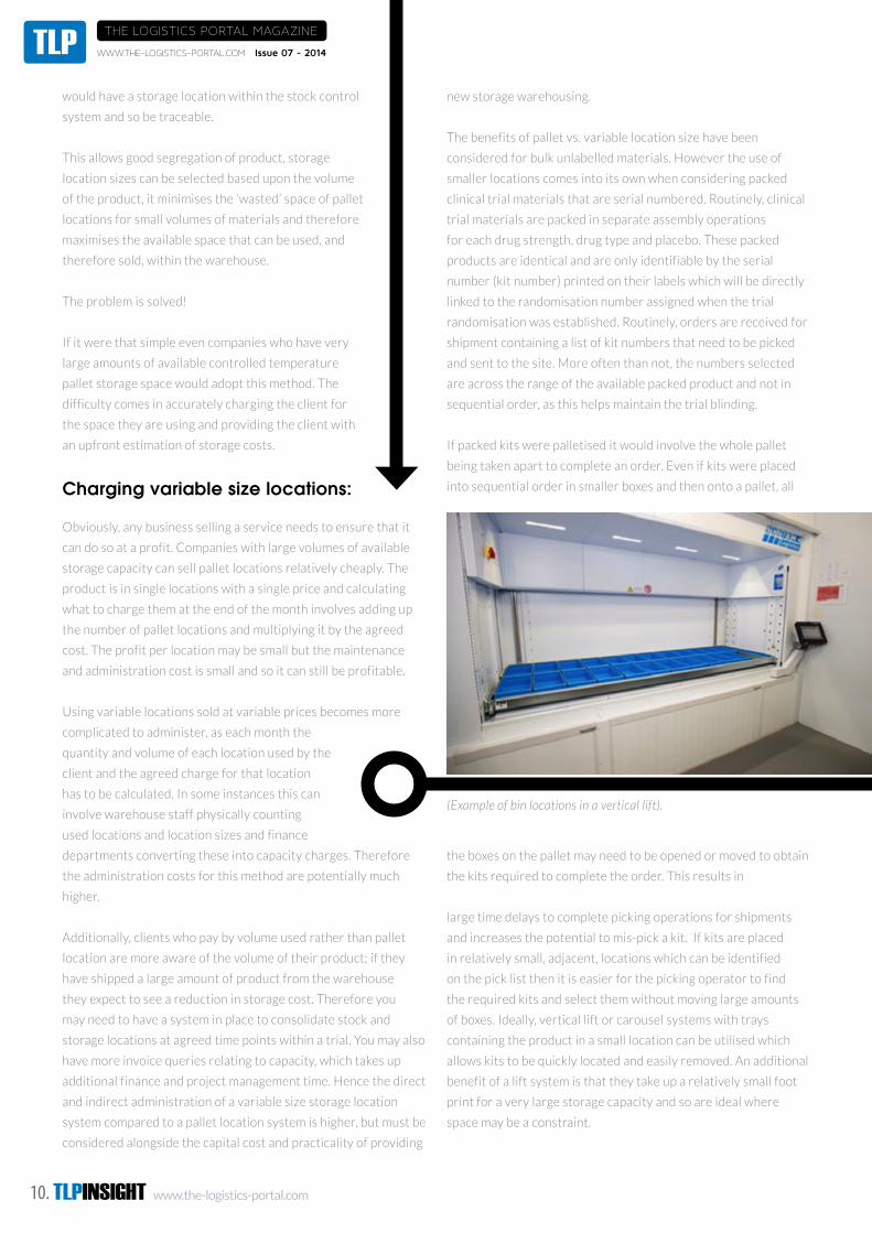
of boxes. Ideally, vertical lift or carousel systems with trays
containing the product in a small location can be utilised which
allows kits to be quickly located and easily removed. An additional
benefit of a lift system is that they take up a relatively small foot
print for a very large storage capacity and so are ideal where
space may be a constraint.
(Example of bin locations in a vertical lift).

Issue 07 - 2014 WWW.THE-LOGISTICS-PORTAL.COM TLPTHE LOGISTICS PORTAL MAGAZINE
Using smaller locations is ideal for serial numbered clinical trial
kits, but this model requires a different method of charging than
pallet locations.
Traditionally, proposals are prepared for clinical trial supplies with
an estimated cost for storage at different temperatures based
upon the client’s forecast for when products will be received,
packed and shipped to site. These forecasts will always be wrong
as manufacturing time scales change, regulatory approvals are
delayed and patient recruitment will be different to that planned.
Using the pallet method of storage, it is simple to predict the
storage volumes for inclusion in proposals. Allocate one pallet per
product, per batch for bulk materials and another one or two for
packed blinded product. These will be required throughout the
trial or can be aligned to packing operations at agreed time points
throughout the trial. Difficulties arise when variable storage
locations are used. For example materials may be received in
pallet quantities, but once packed they will be located into a
vertical lift system. There may be two cost lines on the proposal,
one for pallet storage at the agreed temperature and one for a
location in the vertical lift. However, can the distribution of the
costs between the two types of storage location be estimated on
the proposal? It may be that you have pallet locations until the
predicted packing times and then smaller locations in the vertical
lift until the end of the trial, but product in the lift will reduce over
time as it is shipped to site so this needs to be accounted for. It is
not impossible to calculate, but much more complicated and again
adds to the administration costs for using variable locations.
One method that has been used to try to simplify this issue is to
convert all unit pricing into litre costs. Therefore a pallet location
is 720 litres, each smaller location can be assigned its volume in
litres and based on the volume of product being delivered and
the volume of the packaged kits an estimate of the total number
of litres of storage can be calculated. This at least results in only
one cost line per storage temperature, but still involves a lot
of guess work to estimate the volume of storage required for a
project. And clients may find it difficult to visualise the storage
requirements when based upon litres and locations.
Traceability of product in storage locations.
Traceability of product is an essential part of GMP. If you are
using a method of charging clients based upon locations used, it is
essential that you know which client’s product is in which location
and the size of the location. Therefore upon receipt, the product
must be booked into its location and the specific location should
be assigned a volume. For example, where the unit costs are in
litres every location needs to be assigned a volume in litres.
One method for fast and secure location of stock is via 2D matrix
or barcodes. Upon receipt each packaged unit of drug product
(e.g. box or tray) has a barcode or matrix attached which details
part number, quantity and batch number. Each location and
sub location is barcoded, and so when the product is placed
into storage the barcode of the product and the barcode of the
location are scanned and linked in the stock system. Each month
a report can then be generated per location or per product
identifying the location and assigning a volume being used. This
removes some the additional administration of using variable
stock location sizes.
In summary, where storage is a billable service there are
additional administration costs for monthly billing to clients both
for finance and warehouse. If a company has a large amount of
spare capacity then simple pallet locations would probably be the
most cost effective method of storage of bulk unpacked materials.
Finished kits, particularly when they are serial numbered, require
smaller storage locations to enable efficient picking for shipment.
Where capacity is limited, variable size storage locations would
offer more efficient use of available warehouses and possibly
provide better value to the client. However, these require far
greater administration and can result in a greater number of
client queries both at the proposal stage and during projects as
accurate predictions of capacity across the duration of a project
are virtually impossible to model and so the actual cost of storage
may vary significantly from the original forecast.
Rachel Griffiths – Associate Director
Rachel joined Biotec
Services International in
2004. In her current role
as Associate Director of
Operations, Rachel has
overall responsibility for the
warehouse, production and
project management. She has
a wide range of experience
previously acquired in roles
that include: Development Scientist, Technical Support Scientist
and Product Support Specialist at Ortho Clinical Diagnostics.
Rachel holds a degree in Microbiology and Virology from Warwick
University.
www.biotec-uk.com

TLPINSIGHT www.the-logistics-portal.com12.
THE LOGISTICS PORTAL MAGAZINE
WWW.THE-LOGISTICS-PORTAL.COM Issue 07 - 2014TLP
IATA - DGR54 - Stay Compliant (V7) / The Logistics Portal Jan 2013
full page trim size 210 X 297 mm / safety area 186 X 273 mm
iata.org/dgr
Effective immediately, use the 54th Edition of the DGR Manual or your shipments may be at risk.If you’re not using the 54th Edition of the DGR Manual your dangerous good shipment may not be compliant. Don’t risk having your shipment returned or being fi ned thousands of dollars because of faulty documentation, packing or labeling. Get the 54th edition of the DGR Manual today and be current with the latest regulations for completing the Shipper’s Declaration. Remember, if you use previous editions, you are knowingly putting yourself and your company at serious risk.
Stay Compliant
DDIA00122_DGRad_TheLogisticsPortal_V7.indd 1 2013-01-18 11:31 AM

www.the-logistics-portal.com TLPINSIGHT 13.
The Ultimate Guide to Effective
Temperature Control
in Refrigerated Transport
KEEP YOUR COOL
Presented by
www.the-logistics-portal.com TLPINSIGHT 13.

TLPINSIGHT www.the-logistics-portal.com14.
KEEP YOUR COOL THE ULTIMATE GUIDE TO EFFECTIVE TEMPERATURE CONTROL IN REFRIGERATED TRANSPORT
Transporting temperature sensitive goods can be a very demanding task. Maintaining product at the correct
temperature whilst meeting exacting delivery schedules is a challenge faced by all managers of refrigerated
fleets. With the consequence of a rejected load being so expensive, many businesses can benefit enormously by
utilising an effective temperature monitoring system to help mitigate their risk.
Introduction
The aim of this guide is to describe ways in which temperature
monitoring systems can be used to improve temperature control
during transportation and simultaneously help to lower operating
costs.
Temperature monitoring for refrigerated vehicles can be
undertaken in a number of different ways. This includes individual
battery operated data loggers that accompany the product, air
temperature recorders that are permanently fitted to the vehicle
and complete telematics systems that provide live updates of
temperature status and vehicle positional information.
All these systems have value in helping to improve refrigeration
performance but when temperature monitoring is integrated with
vehicle tracking and telematics, users can employ the combined
system to gain a more complete picture of fleet performance. In
addition the live data provided will help to anticipate temperature
related issues and enable immediate remedial action to be taken.
This improves efficiency and simplifies record keeping whilst
doing everything possible to ensure that temperature controlled
goods are delivered in the best possible condition.
Nowadays it is not uncommon for the value of a trailer load of
refrigerated foodstuffs to exceed £100K. Having visibility of both
the temperature and location of this product provides peace of
mind for fleet managers and instils confidence in their customers.
Knowing as soon as the temperature deviates outside of
acceptable conditions can be the difference between an accepted
or rejected load and this offers huge savings potential. In addition
maintaining refrigerated foodstuffs at the optimum temperature
can help prolong shelf life and thereby reduce wastage.
There are clear benefits in reacting to deviations in temperature;
however, to gain the most value from any temperature monitoring
system, businesses need to use the data to identify areas where
improvements can be made and then drive operational change,
designed to prevent deviations from happening in the first place.
This is probably the biggest challenge that operators face –
making effective use of the data collected in order to implement
change and drive improvement.
However, this is another area where a live telematics based
monitoring system has clear benefits. Most operators will train
their drivers and employ standard procedures for them to follow
but once the vehicle leaves the depot it is extremely difficult to
confirm that the procedures are being followed. Live data capture
can help overcome this issue.

www.the-logistics-portal.com TLPINSIGHT 15.
The Cold Chain can be described as the process involved in the storage and distribution of temperature
sensitive perishables where the temperature and/ or atmosphere should be controlled to maintain product
quality, product safety and thereby help to extend shelf life. This concept applies to frozen and chilled foodstuff,
pharmaceuticals and certain aspects of livestock. It can also apply to various types of high value specialist
products such as antiques and musical instruments.
According to the Laws of Physics there is no such thing as cold, only heat or lack of it. Cold is a human sensation
that can be felt but cannot be measured. However, it is possible to extract heat to make something colder.
Concepts of transport refrigeration systems
How the refrigeration system works
Temperature control in refrigerated transport applies to frozen
and chilled temperatures generally in the range from -30oC to
+15oC. However since the ambient temperature can vary from
lows of -20oC in northern hemisphere countries during winter
to highs of +40oC in southern climates during summer it is also
advantageous for the refrigeration system to be able to generate
heat as well as the ability to refrigerate.
Maintaining temperature sensitive goods at the correct
temperature during transport is necessary to prevent the
growth of pathogenic micro-organisms and the like which would
otherwise make the product unfit for use or consumption.
A refrigeration system is essentially a heat pump.
It does work to move heat from one location to
another. The most common type of refrigeration
system employed in the transport industry is the
vapour/compression cycle system. This uses a
gas, typically a hydrocarbon compound, which can
change phase repeatedly as the gas is alternately
compressed and allowed to condense to form a
liquid and is then expanded so that it evaporates
back into a gas. The evaporation process draws in
heat from the air surrounding the evaporator and
the condensation process gives out heat to the air
surrounding the condenser. See Figure 1.
However the vehicle refrigeration system is not designed to
change the temperature of the products being transported, it
is only intended to maintain the temperature of these products
during the transportation process.
Any Cold Chain should be managed by a quality management
system. This will require the process to be analysed, measured,
controlled, documented, and validated. The food industry uses the
concepts of Hazard Analysis and Critical Control Point, HACCP,
as a means of undertaking these important quality management
procedures.
In summary the operating procedure for transporting temperature sensitive goods is:-
• Pre-cool compartment and defrost if necessary
• Switch off refrigeration unit before opening compartment door
• Insert product/load at the correct temperature
• Distribute load properly
• Surround load with air at the correct temperature
• Minimise the time that the compartment door spends open at the point of delivery
All things being equal, if this procedure is followed, then product will be delivered at the correct temperature.
Accordingly the use of a suitable temperature and event monitoring system can help confirm that the correct procedures have been followed and identify deficiencies or problems as and when they occur to assist with the implementation of corrective action.
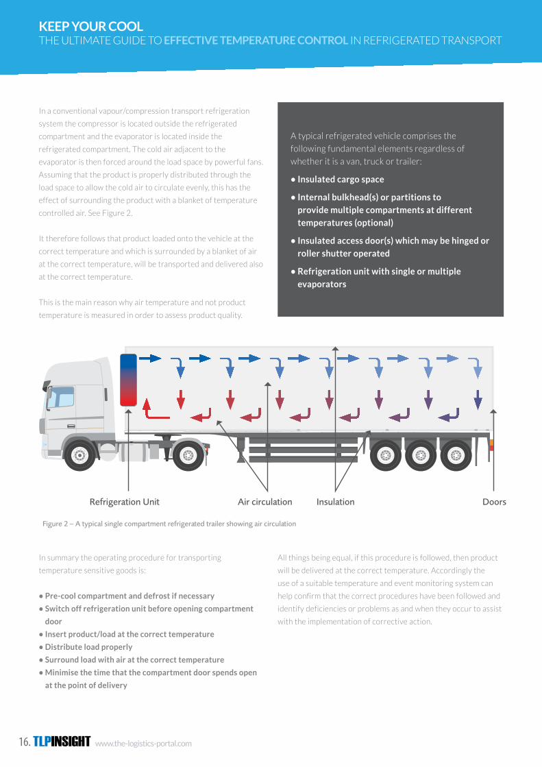
In a conventional vapour/compression transport refrigeration system the compressor is located outside the refrigerated compartment and the evaporator is located inside the refrigerated compartment. The cold air adjacent to the evaporator is then forced around the load space by powerful fans. Assuming that the product is properly distributed through the load space to allow the cold air to circulate evenly, this has the effect of surrounding the product with a blanket of temperature controlled air. See Figure 2.
It therefore follows that product loaded onto the vehicle at the correct temperature and which is surrounded by a blanket of air at the correct temperature, will be transported and delivered also at the correct temperature.
This is the main reason why air temperature and not product temperature is measured in order to assess product quality.
Figure 2 – A typical single compartment refrigerated trailer showing air circulation
A typical refrigerated vehicle comprises the following fundamental elements regardless of whether it is a van, truck or trailer:
• Insulated cargo space
• Internal bulkhead(s) or partitions to provide multiple compartments at different temperatures (optional)
• Insulated access door(s) which may be hinged or roller shutter operated
• Refrigeration unit with single or multiple evaporators
7
Refrigeration Unit Air circulation Insulation Doors
Temperature control in refrigerated transport applies to frozen and chilled temperatures generally in the range from -30oC to +15oC. However since the ambient temperature can vary from lows of -20oC in northern hemisphere countries during winter to highs of +40oC in southern climates during summer it is also advantageous for the refrigeration system to be able to generate heat as well as the ability to refrigerate.
Maintaining temperature sensitive goods at the correct temperature during transport is necessary to prevent the growth of pathogenic micro-organisms and the like which would otherwise make the product unfit for use or
consumption. However the vehicle refrigeration system is not designed to change the temperature of the products being transported, it is only intended to maintain the temperature of these products during the transportation process.
Any Cold Chain should be managed by a quality management system. This will require the process to be analysed, measured, controlled, documented, and validated. The food industry uses the concepts of Hazard Analysis and Critical Control Point, HACCP, as a means of undertaking these important quality management procedures (see section 3.1.1).
2.0 Concepts of transport refrigeration systems
A refrigeration system is essentially a heat pump. It does work to move heat from one location to another. The most common type of refrigeration system employed in the transport industry is the vapour/compression cycle system. This uses a gas, typically a hydrocarbon compound, which can change phase repeatedly as the gas is alternately compressed and allowed to condense to form a liquid and is then expanded so that it evaporates back into a gas. The evaporation process draws in heat from the air surrounding the evaporator and the condensation process gives out heat to the air surrounding the condenser. See Figure 1.
2.1 How the refrigeration system works
The Cold Chain can be described as the process involved in the storage and distribution of temperature sensitive perishables where the temperature and/or atmosphere should be controlled to maintain product quality, product safety and thereby help to extend shelf life. This concept applies to frozen and chilled foodstuff, pharmaceuticals and certain aspects of livestock. It can also apply to various types of high value specialist products such as antiques and musical instruments.
According to the Laws of Physics there is no such thing as cold, only heat or lack of it. Cold is a human sensation that can be felt but cannot be measured. However, it is possible to extract heat to make something colder.
Figure 1 – Vapour compression refrigeration system
6
Heat Transfer
Expansion Vale
Compressor
Cold Air
Evaporator
Warm Air
Condenser
The ultimate guide to effective temperature control in refrigerated transport
TLPINSIGHT www.the-logistics-portal.com16.
KEEP YOUR COOL THE ULTIMATE GUIDE TO EFFECTIVE TEMPERATURE CONTROL IN REFRIGERATED TRANSPORT
In a conventional vapour/compression transport refrigeration
system the compressor is located outside the refrigerated
compartment and the evaporator is located inside the
refrigerated compartment. The cold air adjacent to the
evaporator is then forced around the load space by powerful fans.
Assuming that the product is properly distributed through the
load space to allow the cold air to circulate evenly, this has the
effect of surrounding the product with a blanket of temperature
controlled air. See Figure 2.
It therefore follows that product loaded onto the vehicle at the
correct temperature and which is surrounded by a blanket of air
at the correct temperature, will be transported and delivered also
at the correct temperature.
This is the main reason why air temperature and not product
temperature is measured in order to assess product quality.
In summary the operating procedure for transporting
temperature sensitive goods is:
• Pre-cool compartment and defrost if necessary
• Switch off refrigeration unit before opening compartment
door
• Insert product/load at the correct temperature
• Distribute load properly
• Surround load with air at the correct temperature
• Minimise the time that the compartment door spends open
at the point of delivery
All things being equal, if this procedure is followed, then product
will be delivered at the correct temperature. Accordingly the
use of a suitable temperature and event monitoring system can
help confirm that the correct procedures have been followed and
identify deficiencies or problems as and when they occur to assist
with the implementation of corrective action.
In summary the operating procedure for transporting temperature sensitive goods is:-
• Pre-cool compartment and defrost if necessary
• Switch off refrigeration unit before opening compartment door
• Insert product/load at the correct temperature
• Distribute load properly
• Surround load with air at the correct temperature
• Minimise the time that the compartment door spends open at the point of delivery
All things being equal, if this procedure is followed, then product will be delivered at the correct temperature.
Accordingly the use of a suitable temperature and event monitoring system can help confirm that the correct procedures have been followed and identify deficiencies or problems as and when they occur to assist with the implementation of corrective action.
In a conventional vapour/compression transport refrigeration system the compressor is located outside the refrigerated compartment and the evaporator is located inside the refrigerated compartment. The cold air adjacent to the evaporator is then forced around the load space by powerful fans. Assuming that the product is properly distributed through the load space to allow the cold air to circulate evenly, this has the effect of surrounding the product with a blanket of temperature controlled air. See Figure 2.
It therefore follows that product loaded onto the vehicle at the correct temperature and which is surrounded by a blanket of air at the correct temperature, will be transported and delivered also at the correct temperature.
This is the main reason why air temperature and not product temperature is measured in order to assess product quality.
Figure 2 – A typical single compartment refrigerated trailer showing air circulation
A typical refrigerated vehicle comprises the following fundamental elements regardless of whether it is a van, truck or trailer:
• Insulated cargo space
• Internal bulkhead(s) or partitions to provide multiple compartments at different temperatures (optional)
• Insulated access door(s) which may be hinged or roller shutter operated
• Refrigeration unit with single or multiple evaporators
7
Refrigeration Unit Air circulation Insulation Doors
Temperature control in refrigerated transport applies to frozen and chilled temperatures generally in the range from -30oC to +15oC. However since the ambient temperature can vary from lows of -20oC in northern hemisphere countries during winter to highs of +40oC in southern climates during summer it is also advantageous for the refrigeration system to be able to generate heat as well as the ability to refrigerate.
Maintaining temperature sensitive goods at the correct temperature during transport is necessary to prevent the growth of pathogenic micro-organisms and the like which would otherwise make the product unfit for use or
consumption. However the vehicle refrigeration system is not designed to change the temperature of the products being transported, it is only intended to maintain the temperature of these products during the transportation process.
Any Cold Chain should be managed by a quality management system. This will require the process to be analysed, measured, controlled, documented, and validated. The food industry uses the concepts of Hazard Analysis and Critical Control Point, HACCP, as a means of undertaking these important quality management procedures (see section 3.1.1).
2.0 Concepts of transport refrigeration systems
A refrigeration system is essentially a heat pump. It does work to move heat from one location to another. The most common type of refrigeration system employed in the transport industry is the vapour/compression cycle system. This uses a gas, typically a hydrocarbon compound, which can change phase repeatedly as the gas is alternately compressed and allowed to condense to form a liquid and is then expanded so that it evaporates back into a gas. The evaporation process draws in heat from the air surrounding the evaporator and the condensation process gives out heat to the air surrounding the condenser. See Figure 1.
2.1 How the refrigeration system works
The Cold Chain can be described as the process involved in the storage and distribution of temperature sensitive perishables where the temperature and/or atmosphere should be controlled to maintain product quality, product safety and thereby help to extend shelf life. This concept applies to frozen and chilled foodstuff, pharmaceuticals and certain aspects of livestock. It can also apply to various types of high value specialist products such as antiques and musical instruments.
According to the Laws of Physics there is no such thing as cold, only heat or lack of it. Cold is a human sensation that can be felt but cannot be measured. However, it is possible to extract heat to make something colder.
Figure 1 – Vapour compression refrigeration system
6
Heat Transfer
Expansion Vale
Compressor
Cold Air
Evaporator
Warm Air
Condenser
The ultimate guide to effective temperature control in refrigerated transport
A typical refrigerated vehicle comprises the
following fundamental elements regardless of
whether it is a van, truck or trailer:
• Insulated cargo space
• Internal bulkhead(s) or partitions to
provide multiple compartments at different
temperatures (optional)
• Insulated access door(s) which may be hinged or
roller shutter operated
• Refrigeration unit with single or multiple
evaporators
www.the-logistics-portal.com TLPINSIGHT 17.
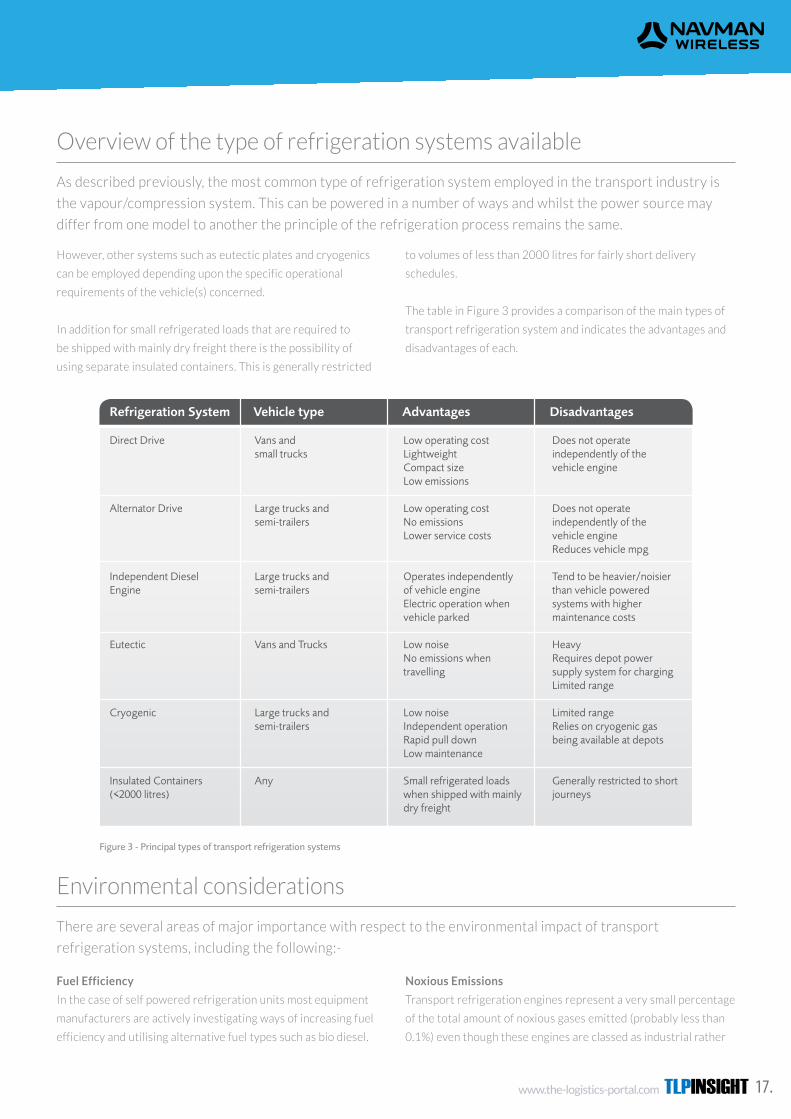
As described previously, the most common type of refrigeration system employed in the transport industry is
the vapour/compression system. This can be powered in a number of ways and whilst the power source may
differ from one model to another the principle of the refrigeration process remains the same.
Overview of the type of refrigeration systems available
However, other systems such as eutectic plates and cryogenics
can be employed depending upon the specific operational
requirements of the vehicle(s) concerned.
In addition for small refrigerated loads that are required to
be shipped with mainly dry freight there is the possibility of
using separate insulated containers. This is generally restricted
to volumes of less than 2000 litres for fairly short delivery
schedules.
The table in Figure 3 provides a comparison of the main types of
transport refrigeration system and indicates the advantages and
disadvantages of each.
Fuel Efficiency In the case of self powered refrigeration units (see section 2.2) most equipment manufacturers are actively investigating ways of increasing fuel efficiency and utilising alternative fuel types such as bio diesel. Noxious Emissions Transport refrigeration engines represent a very small percentage of the total amount of noxious gases emitted (probably less than 0.1%) even though these engines are classed as industrial rather than automotive and have higher inherent emission levels than their automotive equivalent. There is a move towards the drive unit complying with a Euro 5-6 type classification as this will help minimise emission levels further.
Global Warming Potential (GWP) There are specific EU proposals which intend to phase out the use of so called F-gases (Fluorinated ozone friendly refrigerants) such as R404a and R134a. This is currently most likely via a 2 stage approach covering new and existing equipment and will most likely result in the mandatory use of a natural refrigerant with low GWP by around 2020, although this is subject to confirmation. Noise Levels The Piek Regulations, which originated in the Netherlands in 1998 are now becoming more commonly accepted. The regulations lay down maximum noise levels when loading and unloading vehicles during the night. These are 65dBA between 19:00 and 23:00 and 60dBA between 23:00 and 7:00. Many refrigeration equipment manufacturers now specify Piek compliance as standard.
2.3 Environmental considerations
There are several areas of major importance with respect to the environmental impact of transport refrigeration systems, including the following:-
Clearly all refrigeration systems driven from the vehicle engine will benefit from the vehicle’s lower polluting engine and this arrangement will result in an overall lower fuel consumption level.
Of the mechanical options available utectic systems are certainly the best as far as on-road emissions and fuel consumption is concerned but such systems may not be suitable for many applications.
In summary, when considering which type of refrigeration system to use it is recommended that the vehicle operator should take advice from the vehicle supplier/manufacturer and also from the refrigeration system manufacturer with respect to the most suitable technology for the application(s) concerned.
9
However, other systems such as eutectic plates and cryogenics can be employed depending upon the specific operational requirements of the vehicle(s) concerned.
In addition for small refrigerated loads that are required to be shipped with mainly dry freight there is the possibility of using separate insulated containers. This is generally
restricted to volumes of less than 2000 litres for fairly short delivery schedules.
The table in Figure 3 provides a comparison of the main types of transport refrigeration system and indicates the advantages and disadvantages of each.
2.2 Overview of the type of refrigeration systems available
As described in section 2.1, the most common type of refrigeration system employed in the transport industry is the vapour/compression system. This can be powered in a number of ways and whilst the power source may differ from one model to another the principle of the refrigeration process remains the same.
8 The ultimate guide to effective temperature control in refrigerated transport
Refrigeration System Vehicle type Advantages Disadvantages
Direct Drive Alternator Drive Independent Diesel Engine Eutectic Cryogenic Insulated Containers (<2000 litres)
Vans and small trucks Large trucks and semi-trailers Large trucks and semi-trailers Vans and Trucks Large trucks and semi-trailers Any
Low operating costLightweightCompact size Low emissions Low operating costNo emissionsLower service costs Operates independently of vehicle engineElectric operation when vehicle parked Low noiseNo emissions when travelling Low noiseIndependent operationRapid pull downLow maintenance Small refrigerated loads when shipped with mainly dry freight
Does not operate independently of the vehicle engine Does not operate independently of the vehicle engineReduces vehicle mpg Tend to be heavier/noisier than vehicle powered systems with higher maintenance costs HeavyRequires depot power supply system for chargingLimited range Limited rangeRelies on cryogenic gas being available at depots Generally restricted to short journeys
Figure 3 - Principal types of transport refrigeration systems
There are several areas of major importance with respect to the environmental impact of transport
refrigeration systems, including the following:-
Environmental considerations
Fuel Efficiency
In the case of self powered refrigeration units most equipment
manufacturers are actively investigating ways of increasing fuel
efficiency and utilising alternative fuel types such as bio diesel.
Noxious Emissions
Transport refrigeration engines represent a very small percentage
of the total amount of noxious gases emitted (probably less than
0.1%) even though these engines are classed as industrial rather
TLPINSIGHT www.the-logistics-portal.com18.
KEEP YOUR COOL THE ULTIMATE GUIDE TO EFFECTIVE TEMPERATURE CONTROL IN REFRIGERATED TRANSPORT
than automotive and have higher inherent emission levels than
their automotive equivalent. There is a move towards the drive
unit complying with a Euro 5-6 type classification as this will help
minimise emission levels further.
Global Warming Potential (GWP)
There are specific EU proposals which intend to phase out the use
of so called F-gases (Fluorinated ozone friendly refrigerants) such
as R404a and R134a. This is currently most likely via a 2 stage
approach covering new and existing equipment and will most
likely result in the mandatory use of a natural refrigerant with low
GWP by around 2020, although this is subject to confirmation.
Noise Levels
The Piek Regulations, which originated in the Netherlands
in 1998 are now becoming more commonly accepted. The
regulations lay down maximum noise levels when loading and
unloading vehicles during the night. These are 65dBA between
19:00 and 23:00 and 60dBA between 23:00 and 7:00. Many
refrigeration equipment manufacturers now specify Piek
compliance as standard.
Clearly all refrigeration systems driven from the vehicle engine will benefit from the vehicle’s lower polluting
engine and this arrangement will result in an overall lower fuel consumption level.
Of the mechanical options available utectic systems are certainly the best as far as on-road emissions and fuel
consumption is concerned but such systems may not be suitable for many applications.
In summary, when considering which type of refrigeration system to use it is recommended that the vehicle
operator should take advice from the vehicle supplier/manufacturer and also from the refrigeration system
manufacturer with respect to the most suitable technology for the application(s) concerned.
All UK food businesses should ensure that they are familiar with the Food Safety Act 1990
http://www.opsi.gov.uk/acts/acts1990/ukpga_19900016_ en_1.htm which, although has been subject to
substantial change following the introduction of European food safety legislation, remains very important
primary food safety legislation. It has provided the basis and a flexible framework for much domestic food
law and applies to the whole of Great Britain. It concentrates on fundamental issues and leaves the detail to
secondary legislation such as described below.
Legislation and Regulations
Overview of current UK Regulations
Hazard Analysis and Critical Control Points (HACCP)
European Regulation (EC) 852/2004 on the hygiene of foodstuffs
describes the concept of HACCP. This involves identifying
any hazards that must be prevented and eliminating them or
reducing them to acceptable levels. This is done by identifying
critical control points and setting critical limits, establishing
effective monitoring procedures and implementing any necessary
corrective action.
It is therefore clear that as far as temperature sensitive products
are concerned, records of temperature should be made. This
applies both during transport and storage of the product.

www.the-logistics-portal.com TLPINSIGHT 19.
The general requirement for temperature control is set out in (EC) 852/2004 Annex II, Chapter IX, which states:-
Raw materials, ingredients, intermediate products and finished products likely to support the reproduction of pathogenic micro-organisms or the formation of toxins are not to be kept at temperatures that might result in a risk to health. The cold chain is not to be interrupted. However, limited periods outside temperature control are permitted, to accommodate the practicalities of handling during preparation, transport, storage, display and service of food, provided that it does not result in a risk to health.
Regulation (EC) 37/2005 specifies the requirements for monitoring temperatures in the means of transport,
warehousing and storage of quickfrozen foodstuffs intended for human consumption. It states that the means
of transport, warehousing and storage shall be fitted with suitable recording instruments to monitor, at
frequent and regular intervals, the air temperature to which the quick-frozen foodstuffs are subjected.
Quick Frozen Food Regulations (EC) 37/2005
Food Hygiene Regulations (2006) & Due Diligence
(EC) 37/2005 applies to products labelled as quick-frozen or
deep-frozen and this applies to all foodstuff held at a temperature
below -18oC. It excludes ice cream. The regulation also
The Food Hygiene Regulations (2006) covers general food
hygiene requirements for food business operators involved in
foodstuff for human consumption. This involves all aspects of
hygiene and includes temperature control requirements.
The regulations stipulate a maximum holding temperature of
8oC with any upward variation above this maximum limited
to 4 hours.
It follows that when handling, storing or transporting
foodstuffs for human consumption, that have to be held at
specific temperatures, it will be unlikely that it will be possible
to use the defence of Due Diligence for any temperature
related offence unless appropriate temperature records are
taken and maintained.
stipulates that the recording equipment shall comply with EN
standard 12830. However a derogation currently exists for local
distribution where a recorder need not be fitted and an easily
The Regulations also introduce the concept of Due
Diligence, which is described as follows:-
In any proceedings for an offence under the Regulations, it shall be a defence for the accused to prove that he took all reasonable precautions and exercised all due diligence to avoid the commission of the offence by himself or by a person under his control.
TLPINSIGHT www.the-logistics-portal.com20.
KEEP YOUR COOL THE ULTIMATE GUIDE TO EFFECTIVE TEMPERATURE CONTROL IN REFRIGERATED TRANSPORT
visible thermometer which complies with EN Standard 13485 is
acceptable.
Local distribution is defined as movement of goods from a
distribution centre to a retail or catering outlet and primary
distribution generally covers deliveries from the manufacturer to
a regional distribution centre (RDC). Primary distribution is also
sometimes referred to as long distance transport.
EN Standards 12830 and 13485 are type test standards and
Chilled foods generally receive minimal processing and
temperature is the principal controlling factor in their safety. The
commercial storage of chilled foods must comply with The Food
Hygiene (England) Regulations 2006 (SI 2006/14); The Food
Hygiene (Wales) Regulations 2006 (SI 2006/31 (W.5)); and; The
Food Hygiene Regulations (Northern Ireland) 2006 (SR 2006
No 3).
it is the responsibility of the manufacturer of the equipment to
ensure that products supplied comply with the relevant standard.
In addition all temperature monitoring equipment whether
a recorder or an indicator should have its accuracy verified
periodically in accordance with EN Standard 13486 (see section
5.9)
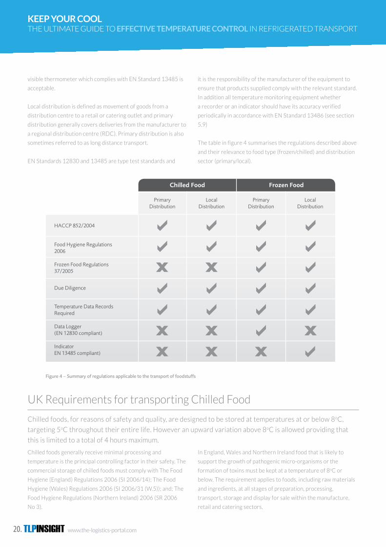
The table in figure 4 summarises the regulations described above
and their relevance to food type (frozen/chilled) and distribution
sector (primary/local).
In England, Wales and Northern Ireland food that is likely to
support the growth of pathogenic micro-organisms or the
formation of toxins must be kept at a temperature of 8oC or
below. The requirement applies to foods, including raw materials
and ingredients, at all stages of preparation, processing,
transport, storage and display for sale within the manufacture,
retail and catering sectors.
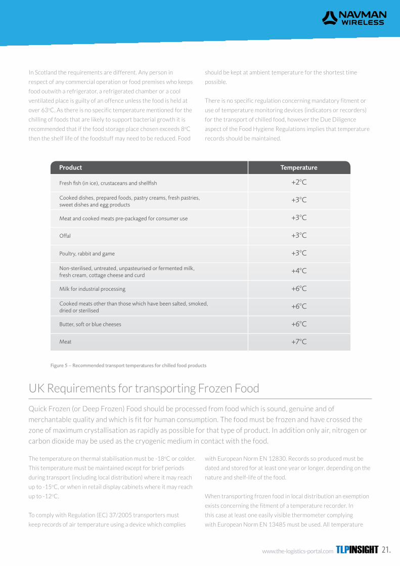
3.2 UK Requirements for transporting Chilled Food
Chilled foods, for reasons of safety and quality, are designed to be stored at temperatures at or below 8oC, targeting 5oC throughout their entire life. However an upward variation above 8oC is allowed providing that this is limited to a total of 4 hours maximum.
Product Temperature
Fresh fish (in ice), crustaceans and shellfish Cooked dishes, prepared foods, pastry creams, fresh pastries, sweet dishes and egg products Meat and cooked meats pre-packaged for consumer use
Offal
Poultry, rabbit and game
Non-sterilised, untreated, unpasteurised or fermented milk, fresh cream, cottage cheese and curd Milk for industrial processing Cooked meats other than those which have been salted, smoked, dried or sterilised Butter, soft or blue cheeses
Meat
+2oC
+3oC
+3oC
+3oC
+3oC
+4oC
+6oC
+6oC
+6oC
+7oC
Figure 5 – Recommended transport temperatures for chilled food products
Chilled foods generally receive minimal processing and temperature is the principal controlling factor in their safety. The commercial storage of chilled foods must comply with The Food Hygiene (England) Regulations 2006 (SI 2006/14); The Food Hygiene (Wales) Regulations 2006 (SI 2006/31 (W.5)); and; The Food Hygiene Regulations (Northern Ireland) 2006 (SR 2006 No 3).
In England, Wales and Northern Ireland food that is likely to support the growth of pathogenic micro-organisms or the formation of toxins must be kept at a temperature of 8oC or below. The requirement applies to foods, including raw materials and ingredients, at all stages of preparation, processing, transport, storage and display for sale within the manufacture, retail and catering sectors.
In Scotland the requirements are different. Any person in respect of any commercial operation or food premises who keeps food outwith a refrigerator, a refrigerated chamber or a cool ventilated place is guilty of an offence unless the food is held at over 63oC. As there is no specific temperature mentioned for the chilling of foods that are likely to support bacterial growth it is recommended that if the food storage place chosen exceeds 8oC then the shelf life of the foodstuff may need to be reduced. Food should be kept at ambient temperature for the shortest time possible.
There is no specific regulation concerning mandatory fitment or use of temperature monitoring devices (indicators or recorders) for the transport of chilled food, however the Due Diligence aspect of the Food Hygiene Regulations implies that temperature records should be maintained (see section 3.1.2 above).
13
3.1.3 Quick Frozen Food Regulations (EC) 37/2005
Regulation (EC) 37/2005 specifies the requirements for monitoring temperatures in the means of transport, warehousing and storage of quick-frozen foodstuffs intended for human consumption. It states that the means of transport, warehousing and storage shall be fitted with suitable recording instruments to monitor, at frequent and regular intervals, the air temperature to which the quick-frozen foodstuffs are subjected.
12 The ultimate guide to effective temperature control in refrigerated transport
Chilled Food Frozen Food
Primary Distribution
HACCP 852/2004
Food Hygiene Regulations 2006 Frozen Food Regulations 37/2005
Due Diligence
Temperature Data Records Required Data Logger (EN 12830 compliant) Indicator EN 13485 compliant)
Primary Distribution
Local Distribution
Local Distribution
Figure 4 – Summary of regulations applicable to the transport of foodstuffs
(EC) 37/2005 applies to products labelled as quick-frozen or deep-frozen and this applies to all foodstuff held at a temperature below -18oC. It excludes ice cream. The regulation also stipulates that the recording equipment shall comply with EN standard 12830. However a derogation currently exists for local distribution where a recorder need not be fitted and an easily visible thermometer which complies with EN Standard 13485 is acceptable.
Local distribution is defined as movement of goods from a distribution centre to a retail or catering outlet and primary distribution generally covers deliveries from the manufacturer to a regional distribution centre (RDC).
Primary distribution is also sometimes referred to as long distance transport.
EN Standards 12830 and 13485 are type test standards and it is the responsibility of the manufacturer of the equipment to ensure that products supplied comply with the relevant standard. In addition all temperature monitoring equipment whether a recorder or an indicator should have its accuracy verified periodically in accordance with EN Standard 13486 (see section 5.9)
The table in figure 4 summarises the regulations described above and their relevance to food type (frozen/chilled) and distribution sector (primary/local).
Chilled foods, for reasons of safety and quality, are designed to be stored at temperatures at or below 8oC,
targeting 5oC throughout their entire life. However an upward variation above 8oC is allowed providing that
this is limited to a total of 4 hours maximum.
UK Requirements for transporting Chilled Food
www.the-logistics-portal.com TLPINSIGHT 21.
The temperature on thermal stabilisation must be -18oC or colder.
This temperature must be maintained except for brief periods
during transport (including local distribution) where it may reach
up to -15oC, or when in retail display cabinets where it may reach
up to -12oC.
To comply with Regulation (EC) 37/2005 transporters must
keep records of air temperature using a device which complies
with European Norm EN 12830. Records so produced must be
dated and stored for at least one year or longer, depending on the
nature and shelf-life of the food.
When transporting frozen food in local distribution an exemption
exists concerning the fitment of a temperature recorder. In
this case at least one easily visible thermometer complying
with European Norm EN 13485 must be used. All temperature
3.2 UK Requirements for transporting Chilled Food
Chilled foods, for reasons of safety and quality, are designed to be stored at temperatures at or below 8oC, targeting 5oC throughout their entire life. However an upward variation above 8oC is allowed providing that this is limited to a total of 4 hours maximum.
Product Temperature
Fresh fish (in ice), crustaceans and shellfish Cooked dishes, prepared foods, pastry creams, fresh pastries, sweet dishes and egg products Meat and cooked meats pre-packaged for consumer use
Offal
Poultry, rabbit and game
Non-sterilised, untreated, unpasteurised or fermented milk, fresh cream, cottage cheese and curd Milk for industrial processing Cooked meats other than those which have been salted, smoked, dried or sterilised Butter, soft or blue cheeses
Meat
+2oC
+3oC
+3oC
+3oC
+3oC
+4oC
+6oC
+6oC
+6oC
+7oC
Figure 5 – Recommended transport temperatures for chilled food products
Chilled foods generally receive minimal processing and temperature is the principal controlling factor in their safety. The commercial storage of chilled foods must comply with The Food Hygiene (England) Regulations 2006 (SI 2006/14); The Food Hygiene (Wales) Regulations 2006 (SI 2006/31 (W.5)); and; The Food Hygiene Regulations (Northern Ireland) 2006 (SR 2006 No 3).
In England, Wales and Northern Ireland food that is likely to support the growth of pathogenic micro-organisms or the formation of toxins must be kept at a temperature of 8oC or below. The requirement applies to foods, including raw materials and ingredients, at all stages of preparation, processing, transport, storage and display for sale within the manufacture, retail and catering sectors.
In Scotland the requirements are different. Any person in respect of any commercial operation or food premises who keeps food outwith a refrigerator, a refrigerated chamber or a cool ventilated place is guilty of an offence unless the food is held at over 63oC. As there is no specific temperature mentioned for the chilling of foods that are likely to support bacterial growth it is recommended that if the food storage place chosen exceeds 8oC then the shelf life of the foodstuff may need to be reduced. Food should be kept at ambient temperature for the shortest time possible.
There is no specific regulation concerning mandatory fitment or use of temperature monitoring devices (indicators or recorders) for the transport of chilled food, however the Due Diligence aspect of the Food Hygiene Regulations implies that temperature records should be maintained (see section 3.1.2 above).
13
3.1.3 Quick Frozen Food Regulations (EC) 37/2005
Regulation (EC) 37/2005 specifies the requirements for monitoring temperatures in the means of transport, warehousing and storage of quick-frozen foodstuffs intended for human consumption. It states that the means of transport, warehousing and storage shall be fitted with suitable recording instruments to monitor, at frequent and regular intervals, the air temperature to which the quick-frozen foodstuffs are subjected.
12 The ultimate guide to effective temperature control in refrigerated transport
Chilled Food Frozen Food
Primary Distribution
HACCP 852/2004
Food Hygiene Regulations 2006 Frozen Food Regulations 37/2005
Due Diligence
Temperature Data Records Required Data Logger (EN 12830 compliant) Indicator EN 13485 compliant)
Primary Distribution
Local Distribution
Local Distribution
Figure 4 – Summary of regulations applicable to the transport of foodstuffs
(EC) 37/2005 applies to products labelled as quick-frozen or deep-frozen and this applies to all foodstuff held at a temperature below -18oC. It excludes ice cream. The regulation also stipulates that the recording equipment shall comply with EN standard 12830. However a derogation currently exists for local distribution where a recorder need not be fitted and an easily visible thermometer which complies with EN Standard 13485 is acceptable.
Local distribution is defined as movement of goods from a distribution centre to a retail or catering outlet and primary distribution generally covers deliveries from the manufacturer to a regional distribution centre (RDC).
Primary distribution is also sometimes referred to as long distance transport.
EN Standards 12830 and 13485 are type test standards and it is the responsibility of the manufacturer of the equipment to ensure that products supplied comply with the relevant standard. In addition all temperature monitoring equipment whether a recorder or an indicator should have its accuracy verified periodically in accordance with EN Standard 13486 (see section 5.9)
The table in figure 4 summarises the regulations described above and their relevance to food type (frozen/chilled) and distribution sector (primary/local).
Quick Frozen (or Deep Frozen) Food should be processed from food which is sound, genuine and of
merchantable quality and which is fit for human consumption. The food must be frozen and have crossed the
zone of maximum crystallisation as rapidly as possible for that type of product. In addition only air, nitrogen or
carbon dioxide may be used as the cryogenic medium in contact with the food.
UK Requirements for transporting Frozen Food
In Scotland the requirements are different. Any person in
respect of any commercial operation or food premises who keeps
food outwith a refrigerator, a refrigerated chamber or a cool
ventilated place is guilty of an offence unless the food is held at
over 63oC. As there is no specific temperature mentioned for the
chilling of foods that are likely to support bacterial growth it is
recommended that if the food storage place chosen exceeds 8oC
then the shelf life of the foodstuff may need to be reduced. Food
should be kept at ambient temperature for the shortest time
possible.
There is no specific regulation concerning mandatory fitment or
use of temperature monitoring devices (indicators or recorders)
for the transport of chilled food, however the Due Diligence
aspect of the Food Hygiene Regulations implies that temperature
records should be maintained.

TLPINSIGHT www.the-logistics-portal.com22.
KEEP YOUR COOL THE ULTIMATE GUIDE TO EFFECTIVE TEMPERATURE CONTROL IN REFRIGERATED TRANSPORT
monitoring equipment, whether a recorder or an indicator, should
have its accuracy verified periodically in accordance with
EN standard 13486.
3.4 Pharmaceuticals
3.5 Livestock
Pharmaceutical manufacturers and distributors are required to adhere to defined legislation or guidelines covering the production, packaging, storage and distribution of medicinal products for human use. It is the responsibility of the product licence holder to ensure that the product is handled, stored and transported under conditions which will not adversely affect the quality and efficacy of the product. The primary aim being to guarantee patient safety.
The regulations concerning temperature control during the transportation of livestock in conjunction with a business or commercial activity are very specific. European Regulation EC 1/2005 specifies mandatory requirements for temperature control and the fitment of a “Navigation System”. The latter term is used to describe what is, in effect, a tracking system since it covers the requirement to produce an automated journey log.
There are numerous and varied legislative procedures for the pharmaceutical industry which cover Good Manufacturing Practice (GMP) and Good Distribution Practice (GDP). However, whilst none of these is specific in terms of defining the type of monitoring equipment that is to be used, the very nature of the pharmaceuticals business almost guarantees that sophisticated monitoring systems including temperature recording and tracking will be employed by virtually all distribution companies.
European Council Directive 92/25/EEC of March 1992 describes the requirements and process to be followed in order to obtain authorisation to distribute pharmaceuticals and states that records must be produced and kept for 5 years.
The EU Guidelines on Good Distribution Practice of Medicinal Products for Human Use, document 94/C 63/03 underlines the 5 year period of retention and states that records should ensure that “all significant activities or events are traceable”.
Most pharmaceutical transporters in Europe will only secure contracts to carry goods following an audit by the manufacturer or product licence holder. This will entail temperature profiling of the refrigerated compartment and regular calibration checks of the temperature recorder equipment. The use of a tracking system is not mandatory and usually depends on the length of the journey and/or critical nature of the goods.
Derogations exist in the UK for journeys of less than 12 hours duration to the final destination.
The regulation states that a ventilation system must be fitted to the vehicle and that this must be designed, constructed and maintained in such a way that, at any time during the journey, whether the vehicle is stationary or moving, it is capable of maintaining a range of temperatures from 5oC to 30oC within the vehicle, for all animals, with a ±5oC tolerance, depending on the outside temperature.
DEFRA has produced guidelines on the requirements of the tracking/temperature monitoring system which can be found here:
http://www.gov.uk/government/uploads/system/uploads/attachment_data/file/193680/pb13550-wato-guidance.pdf
15
3.3 UK Requirements for transporting Frozen Food
Quick Frozen (or Deep Frozen) Food should be processed from food which is sound, genuine and of merchantable quality and which is fit for human consumption. The food must be frozen and have crossed the zone of maximum crystallisation as rapidly as possible for that type of product. In addition only air, nitrogen or carbon dioxide may be used as the cryogenic medium in contact with the food.
14 The ultimate guide to effective temperature control in refrigerated transport
Figure 6 - Recommended transport temperatures for frozen food products
The temperature on thermal stabilisation must be -18oC or colder. This temperature must be maintained except for brief periods during transport (including local distribution) where it may reach up to -15oC, or when in retail display cabinets where it may reach up to -12oC.
To comply with Regulation (EC) 37/2005 transporters must keep records of air temperature using a device which complies with European Norm EN 12830. This is described in more detail in section 3.1.3 above. Records so produced must be dated and stored for at least one year or longer, depending on the nature and shelf-life of the food.
When transporting frozen food in local distribution an exemption exists concerning the fitment of a temperature recorder. In this case at least one easily visible thermometer complying with European Norm EN 13485 must be used.
All temperature monitoring equipment, whether a recorder or an indicator, should have its accuracy verified periodically in accordance with EN standard 13486 (see section 5.9).
Product Temperature
Ice and Ice cream
Deep frozen foods
Fishery products
Butter and edible fats, including cream to be used for butter making
Egg products, offal, rabbit, poultry and game
Meat
-25oC
-18oC
-18oC
-14oC
-12oC
-10oC
There are numerous and varied legislative procedures for the
pharmaceutical industry which cover Good Manufacturing
Practice (GMP) and Good Distribution Practice (GDP). However,
whilst none of these is specific in terms of defining the type of
monitoring equipment that is to be used, the very nature of the
pharmaceuticals business almost guarantees that sophisticated
monitoring systems including temperature recording and tracking
will be employed by virtually all distribution companies.
European Council Directive 92/25/EEC of March 1992 describes
the requirements and process to be followed in order to obtain
authorisation to distribute pharmaceuticals and states that
records must be produced and kept for 5 years.
The EU Guidelines on Good Distribution Practice of Medicinal
Products for Human Use, document 94/C 63/03 underlines the
5 year period of retention and states that records should ensure
that “all significant activities or events are traceable”.
Most pharmaceutical transporters in Europe will only secure
contracts to carry goods following an audit by the manufacturer
or product licence holder. This will entail temperature profiling
of the refrigerated compartment and regular calibration checks
of the temperature recorder equipment. The use of a tracking
system is not mandatory and usually depends on the length of the
journey and/or critical nature of the goods.
Pharmaceutical manufacturers and distributors are required to adhere to defined legislation or guidelines
covering the production, packaging, storage and distribution of medicinal products for human use. It is the
responsibility of the product licence holder to ensure that the product is handled, stored and transported
under conditions which will not adversely affect the quality and efficacy of the product. The primary aim being
to guarantee patient safety.
Pharmaceuticals

www.the-logistics-portal.com TLPINSIGHT 23.
Derogations exist in the UK for journeys of less than 12 hours
duration to the final destination.
The regulation states that a ventilation system must be fitted
to the vehicle and that this must be designed, constructed and
maintained in such a way that, at any time during the journey,
whether the vehicle is stationary or moving, it is capable of
maintaining a range of temperatures from 5oC to 30oC within the
vehicle, for all animals, with a ±5oC tolerance, depending on the
outside temperature.
A rigid semi-trailer bodywork normally consists of expanded foam
insulation sandwiched between two external skins. The most
popular insulation is expanded polyurethane (PU) foam. For side
walls where thickness is constrained by the maximum permissible
insulated vehicle width of 2.60m and metric pallet dimensions
(a metric pallet is 1.0m deep by 1.20m wide), this construction
can accommodate 2 metric pallets side by side but insulation
thickness is limited.
DEFRA has produced guidelines on the requirements of the
tracking/temperature monitoring system which can be found
here:
http://www.gov.uk/government/uploads/system/uploads/
attachment_data/file/193680/pb13550- wato-guidance.pdf
Another popular insulation material is extruded polystyrene
(styrofoam). The thermal conductivity of this insulation is higher
than PU foam but in floor and roof construction where there
are fewer constraints for overall thickness, vehicle bodybuilders
can offset thermal losses by using thicker panels. Roofs and
floors often have 100 mm or more insulation. For side walls, the
constraints mean the insulation is rarely more than 45-60mm
thick.
The performance of insulation
materials deteriorates with time due
to the inherent characteristics of
the foam. A typical loss of insulation
value of between 3% and 5% per year
is not uncommon and this can lead
to considerable rises in the thermal
conductivity after just a few years.
This will result in an increase in energy
consumption and CO2 emissions for the
refrigeration system employed.
Many factors have to be taken into account in the design and construction of a refrigerated vehicle. Extremes
of exterior weather conditions, desired interior temperatures, insulation properties, infiltration of air and
moisture, trade-offs between construction cost and operating costs and physical deterioration from shocks and
vibration all have to be considered.
The regulations concerning temperature control during the transportation of livestock in conjunction with
a business or commercial activity are very specific. European Regulation EC 1/2005 specifies mandatory
requirements for temperature control and the fitment of a “Navigation System”. The latter term is used to
describe what is, in effect, a tracking system since it covers the requirement to produce an automated
journey log.
Refrigerated vehicle construction and ATP requirements
Livestock
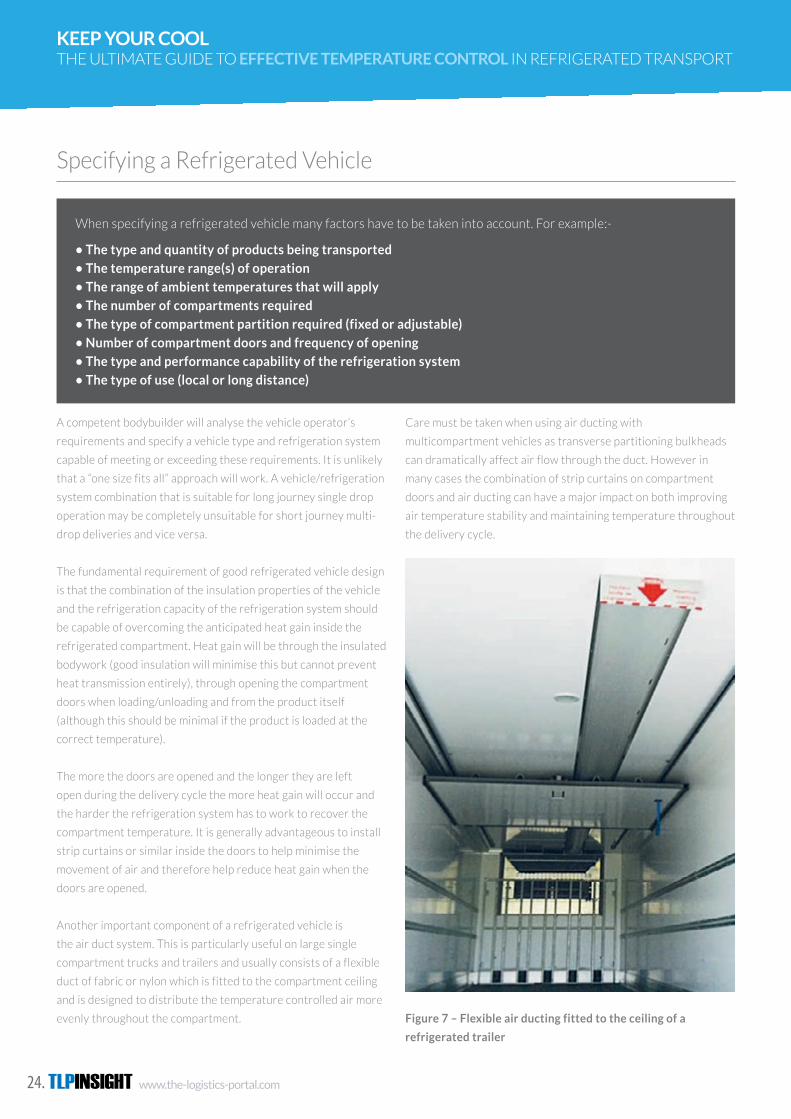
TLPINSIGHT www.the-logistics-portal.com24.
KEEP YOUR COOL THE ULTIMATE GUIDE TO EFFECTIVE TEMPERATURE CONTROL IN REFRIGERATED TRANSPORT
Specifying a Refrigerated Vehicle
A competent bodybuilder will analyse the vehicle operator’s
requirements and specify a vehicle type and refrigeration system
capable of meeting or exceeding these requirements. It is unlikely
that a “one size fits all” approach will work. A vehicle/refrigeration
system combination that is suitable for long journey single drop
operation may be completely unsuitable for short journey multi-
drop deliveries and vice versa.
The fundamental requirement of good refrigerated vehicle design
is that the combination of the insulation properties of the vehicle
and the refrigeration capacity of the refrigeration system should
be capable of overcoming the anticipated heat gain inside the
refrigerated compartment. Heat gain will be through the insulated
bodywork (good insulation will minimise this but cannot prevent
heat transmission entirely), through opening the compartment
doors when loading/unloading and from the product itself
(although this should be minimal if the product is loaded at the
correct temperature).
The more the doors are opened and the longer they are left
open during the delivery cycle the more heat gain will occur and
the harder the refrigeration system has to work to recover the
compartment temperature. It is generally advantageous to install
strip curtains or similar inside the doors to help minimise the
movement of air and therefore help reduce heat gain when the
doors are opened.
Another important component of a refrigerated vehicle is
the air duct system. This is particularly useful on large single
compartment trucks and trailers and usually consists of a flexible
duct of fabric or nylon which is fitted to the compartment ceiling
and is designed to distribute the temperature controlled air more
evenly throughout the compartment.
Care must be taken when using air ducting with
multicompartment vehicles as transverse partitioning bulkheads
can dramatically affect air flow through the duct. However in
many cases the combination of strip curtains on compartment
doors and air ducting can have a major impact on both improving
air temperature stability and maintaining temperature throughout
the delivery cycle.
Figure 7 – Flexible air ducting fitted to the ceiling of a
refrigerated trailer
When specifying a refrigerated vehicle many factors have to be taken into account. For example:-
• The type and quantity of products being transported
• The temperature range(s) of operation
• The range of ambient temperatures that will apply
• The number of compartments required
• The type of compartment partition required (fixed or adjustable)
• Number of compartment doors and frequency of opening
• The type and performance capability of the refrigeration system
• The type of use (local or long distance)
www.the-logistics-portal.com TLPINSIGHT 25.
The UK acceded to the agreement on the 5 October 1979, and it
entered into force one year later 5 October 1980.
ATP provides a multi-lateral agreement between Signatory
Countries (Contracting Parties) for overland cross-border
carriage of perishable foodstuffs. The purpose is to facilitate
international traffic by setting common internationally recognised
standards.
Fruit and vegetables unless processed are outside the scope of
ATP, as is air transport.
In the UK, The Refrigerated Vehicle Test Centre (RVTC), a division
of Cambridge Refrigeration Technology (CRT), are contracted by
the Department for Transport (DfT) to be the certifying authority
of vehicles.
RVTC produce on behalf of the UK government’s Department for
Transport ATP certificates, ATP plates, replacement certificates
and carry out type approvals and factory inspections. CRT also
provides relevant testing facilities for insulated vehicles and
refrigeration machinery in their environmental chambers and
calorimeters.
For the road haulage operator only delivering foodstuffs in the
UK, there is no legislative requirement for ATP. However for
operators travelling on international journeys an ATP certificate
is nearly always essential. It is illegal to transport perishable
foodstuffs across an international boundary between countries
The agreement on the International Carriage of Perishable Foodstuffs and on the special equipment to be used
for such carriage, known as the ATP agreement (after its French initials) was drawn up by the Inland Transport
Committee of the United Nations Economic Committee for Europe in 1970-71.
ATP
that are signatories to the agreement unless the vehicle has an
ATP certificate. If you do this you could be stopped, turned back
and even incur a substantial fine!
In France, Spain, Portugal and Italy, where refrigerated vehicles
are found carrying perishable produce without a valid ATP
certificate or plate, they are heavily fined on the spot, and in some
cases are forced to transfer the load to a vehicle which is carrying
its certificate or displaying its ATP plate.
The countries that are signatories to the ATP agreement are as
follows:-
Albania, Andorra, Austria, Azerbaijan, Belarus, Belgium, Bosnia
and Herzegovina, Bulgaria, Croatia, Czech Republic, Denmark,
Estonia, Finland, France, Georgia, Germany, Greece, Hungary,
Ireland, Italy, Kazakhstan, Kyrgyzstan, Latvia, Lithuania,
Luxembourg, Monaco, Montenegro, Morocco, Netherlands,
Norway, Poland, Portugal, Republic of Moldova, Romania, Russian
Federation, Serbia, Slovakia, Slovenia, Spain, Sweden, The former
Yugoslav Republic of Macedonia, Tunisia, Turkey, Ukraine, United
Kingdom, United States of America, Uzbekistan.
There are two classifications for insulated equipment, six for
total-loss refrigerated, twelve for mechanical refrigerated and
three for heated equipment. The most used classifications are
insulated and insulated mechanically refrigerated. Common ATP
Classifications are as shown in figure 8.
The agreement details the following:
• Lists foodstuffs to be carried in accordance with the ATP agreement and sets the warmest permissible
temperature for types of cargo.
• Lays down common standards for temperature controlled transport vehicles such as roadvehicles, railway
wagons and (for sea journeys under 150km) sea containers.
• Sets down the tests to be done on such equipment to ensure that they meet the required standards.
• Provides the system of certification for equipment that conforms to the standards.
• Requires all contracting parties to recognise certificates issued in accordance with the agreement by the
competent authorities of other contracting parties.
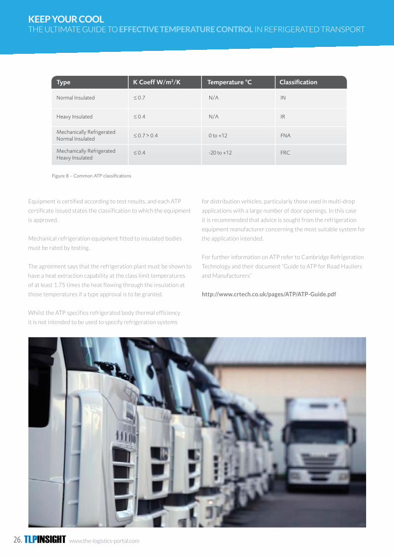
TLPINSIGHT www.the-logistics-portal.com26.
KEEP YOUR COOL THE ULTIMATE GUIDE TO EFFECTIVE TEMPERATURE CONTROL IN REFRIGERATED TRANSPORT
Equipment is certified according to test results, and each ATP certificate issued states the classification to which the equipment is approved.
Mechanical refrigeration equipment fitted to insulated bodies must be rated by testing.
The agreement says that the refrigeration plant must be shown to have a heat extraction capability at the class limit temperatures of at least 1.75 times the heat flowing through the insulation at those temperatures if a type approval is to be granted.
Whilst the ATP specifies refrigerated body thermal
efficiency it is not intended to be used to specify refrigeration systems for distribution vehicles, particularly those used in multi-drop applications with a large number of door openings. In this case it is recommended that advice is sought from the refrigeration equipment manufacturer concerning the most suitable system for the application intended.
For further information on ATP refer to Cambridge Refrigeration Technology and their document “Guide to ATP for Road Hauliers and Manufacturers”
http://www.crtech.co.uk/pages/ATP/ATP-Guide.pdf
Type K Coeff W/m2/K Temperature oC Classification
Normal Insulated
Heavy Insulated
Mechanically Refrigerated Normal Insulated
Mechanically Refrigerated Heavy Insulated
≤ 0.7
≤ 0.4
≤ 0.7 > 0.4
≤ 0.4
N/A
N/A
0 to +12
-20 to +12
IN
IR
FNA
FRC
Figure 8 – Common ATP classifications
19
4.2 ATP
The agreement on the International Carriage of Perishable Foodstuffs and on the special equipment to be used for such carriage, known as the ATP agreement (after its French initials) was drawn up by the Inland Transport Committee of the United Nations Economic Committee for Europe in 1970-71.
18 The ultimate guide to effective temperature control in refrigerated transport
The UK acceded to the agreement on the 5 October 1979, and it entered into force one year later 5 October 1980.
ATP provides a multi-lateral agreement between Signatory Countries (Contracting Parties) for overland cross-border carriage of perishable foodstuffs. The purpose is to facilitate international traffic by setting common internationally recognised standards.
Fruit and vegetables unless processed are outside the scope of ATP, as is air transport.
In the UK, The Refrigerated Vehicle Test Centre (RVTC), a division of Cambridge Refrigeration Technology (CRT), are contracted by the Department for Transport (DfT) to be the certifying authority of vehicles.
RVTC produce on behalf of the UK government’s Department for Transport ATP certificates, ATP plates, replacement certificates and carry out type approvals
and factory inspections. CRT also provides relevant testing facilities for insulated vehicles and refrigeration machinery in their environmental chambers and calorimeters.
For the road haulage operator only delivering foodstuffs in the UK, there is no legislative requirement for ATP. However for operators travelling on international journeys an ATP certificate is nearly always essential. It is illegal to transport perishable foodstuffs across an international boundary between countries that are signatories to the agreement unless the vehicle has an ATP certificate. If you do this you could be stopped, turned back and even incur a substantial fine!
In France, Spain, Portugal and Italy, where refrigerated vehicles are found carrying perishable produce without a valid ATP certificate or plate, they are heavily fined on the spot, and in some cases are forced to transfer the load to a vehicle which is carrying its certificate or displaying its ATP plate.
The countries that are signatories to the ATP agreement are as follows:-
Albania, Andorra, Austria, Azerbaijan, Belarus, Belgium, Bosnia and Herzegovina, Bulgaria, Croatia, Czech Republic, Denmark, Estonia, Finland, France, Georgia, Germany, Greece, Hungary, Ireland, Italy, Kazakhstan, Kyrgyzstan, Latvia, Lithuania, Luxembourg, Monaco, Montenegro, Morocco, Netherlands, Norway, Poland, Portugal, Republic of Moldova, Romania, Russian Federation, Serbia, Slovakia, Slovenia, Spain, Sweden, The former Yugoslav Republic of Macedonia, Tunisia, Turkey, Ukraine, United Kingdom, United States of America, Uzbekistan.
There are two classifications for insulated equipment, six for total-loss refrigerated, twelve for mechanical refrigerated and three for heated equipment. The most used classifications are insulated and insulated mechanically refrigerated. Common ATP Classifications are as shown in figure 8.
The agreement details the following:
• Lists foodstuffs to be carried in accordance with the ATP agreement and sets the warmest permissible temperature for types of cargo.
• Lays down common standards for temperature controlled transport vehicles such as road vehicles, railway wagons and (for sea journeys under 150km) sea containers.
• Sets down the tests to be done on such equipment to ensure that they meet the required standards.
• Provides the system of certification for equipment that conforms to the standards.
• Requires all contracting parties to recognise certificates issued in accordance with the agreement by the competent authorities of other contracting parties.
Equipment is certified according to test results, and each ATP
certificate issued states the classification to which the equipment
is approved.
Mechanical refrigeration equipment fitted to insulated bodies
must be rated by testing.
The agreement says that the refrigeration plant must be shown to
have a heat extraction capability at the class limit temperatures
of at least 1.75 times the heat flowing through the insulation at
those temperatures if a type approval is to be granted.
Whilst the ATP specifies refrigerated body thermal efficiency
it is not intended to be used to specify refrigeration systems
for distribution vehicles, particularly those used in multi-drop
applications with a large number of door openings. In this case
it is recommended that advice is sought from the refrigeration
equipment manufacturer concerning the most suitable system for
the application intended.
For further information on ATP refer to Cambridge Refrigeration
Technology and their document “Guide to ATP for Road Hauliers
and Manufacturers”
http://www.crtech.co.uk/pages/ATP/ATP-Guide.pdf
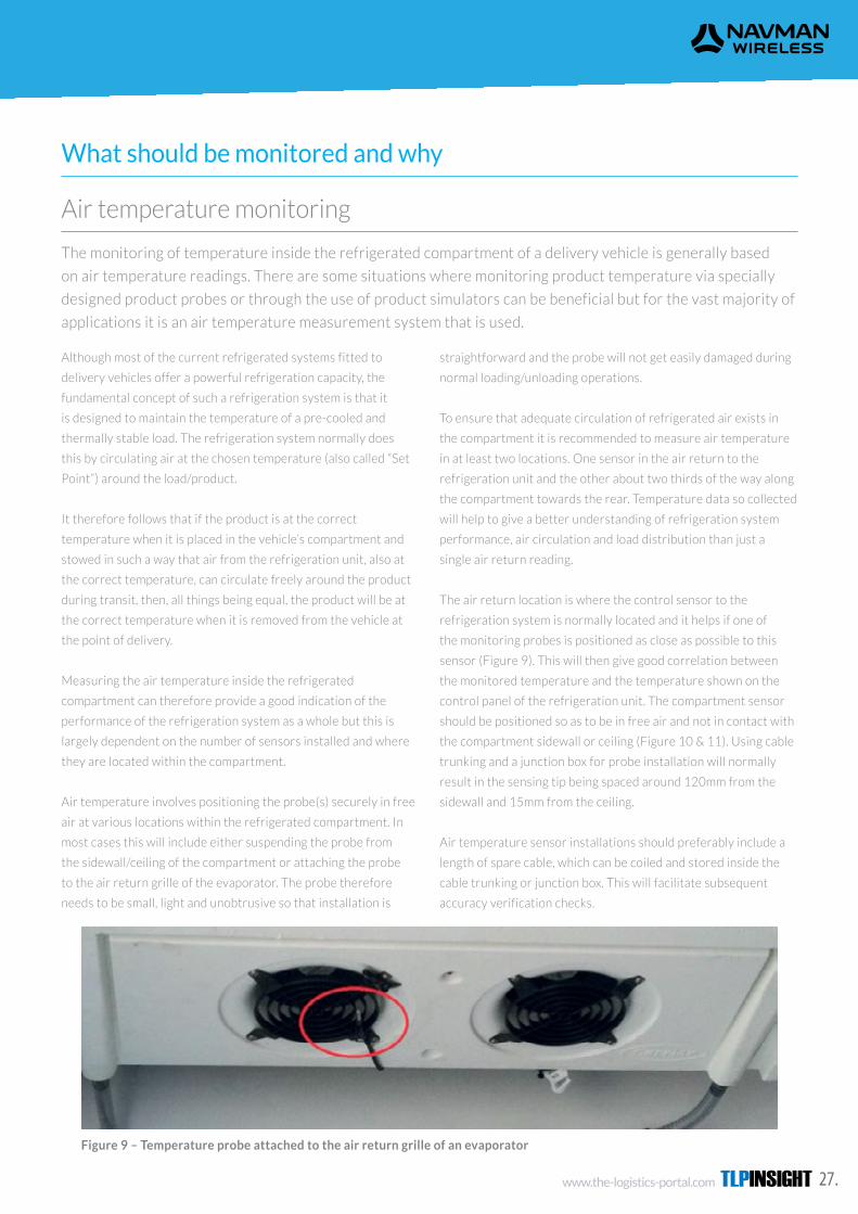
www.the-logistics-portal.com TLPINSIGHT 27.
The monitoring of temperature inside the refrigerated compartment of a delivery vehicle is generally based
on air temperature readings. There are some situations where monitoring product temperature via specially
designed product probes or through the use of product simulators can be beneficial but for the vast majority of
applications it is an air temperature measurement system that is used.
What should be monitored and why
Air temperature monitoring
Although most of the current refrigerated systems fitted to
delivery vehicles offer a powerful refrigeration capacity, the
fundamental concept of such a refrigeration system is that it
is designed to maintain the temperature of a pre-cooled and
thermally stable load. The refrigeration system normally does
this by circulating air at the chosen temperature (also called “Set
Point”) around the load/product.
It therefore follows that if the product is at the correct
temperature when it is placed in the vehicle’s compartment and
stowed in such a way that air from the refrigeration unit, also at
the correct temperature, can circulate freely around the product
during transit, then, all things being equal, the product will be at
the correct temperature when it is removed from the vehicle at
the point of delivery.
Measuring the air temperature inside the refrigerated
compartment can therefore provide a good indication of the
performance of the refrigeration system as a whole but this is
largely dependent on the number of sensors installed and where
they are located within the compartment.
Air temperature involves positioning the probe(s) securely in free
air at various locations within the refrigerated compartment. In
most cases this will include either suspending the probe from
the sidewall/ceiling of the compartment or attaching the probe
to the air return grille of the evaporator. The probe therefore
needs to be small, light and unobtrusive so that installation is
straightforward and the probe will not get easily damaged during
normal loading/unloading operations.
To ensure that adequate circulation of refrigerated air exists in
the compartment it is recommended to measure air temperature
in at least two locations. One sensor in the air return to the
refrigeration unit and the other about two thirds of the way along
the compartment towards the rear. Temperature data so collected
will help to give a better understanding of refrigeration system
performance, air circulation and load distribution than just a
single air return reading.
The air return location is where the control sensor to the
refrigeration system is normally located and it helps if one of
the monitoring probes is positioned as close as possible to this
sensor (Figure 9). This will then give good correlation between
the monitored temperature and the temperature shown on the
control panel of the refrigeration unit. The compartment sensor
should be positioned so as to be in free air and not in contact with
the compartment sidewall or ceiling (Figure 10 & 11). Using cable
trunking and a junction box for probe installation will normally
result in the sensing tip being spaced around 120mm from the
sidewall and 15mm from the ceiling.
Air temperature sensor installations should preferably include a
length of spare cable, which can be coiled and stored inside the
cable trunking or junction box. This will facilitate subsequent
accuracy verification checks.
Figure 9 – Temperature probe attached to the air return grille of an evaporator

TLPINSIGHT www.the-logistics-portal.com28.
KEEP YOUR COOL THE ULTIMATE GUIDE TO EFFECTIVE TEMPERATURE CONTROL IN REFRIGERATED TRANSPORT
Figure 10 – Compartment Probe in free air – with a
junction box
Figure 11 – Compartment Probe in free air – without a
junction box
Figure 12 – Typical temperature probe locations for a single compartment vehicle
Figure 9 – Temperature probe attached to the air return grille of an evaporator
Figure 10 – Compartment Probe in free air – with a junction box Figure 11 – Compartment Probe in free air – without a junction box
Air Return Compartment
21
5.0 What should be monitored and why
5.1 Air temperature monitoring
20 The ultimate guide to effective temperature control in refrigerated transport
The monitoring of temperature inside the refrigerated compartment of a delivery vehicle is generally based on air temperature readings. There are some situations where monitoring product temperature via specially designed product probes or through the use of product simulators can be beneficial but for the vast majority of applications it is an air temperature measurement system that is used.
Although most of the current refrigerated systems fitted to delivery vehicles offer a powerful refrigeration capacity, the fundamental concept of such a refrigeration system is that it is designed to maintain the temperature of a pre-cooled and thermally stable load. The refrigeration system normally does this by circulating air at the chosen temperature (also called “Set Point”) around the load/product.
It therefore follows that if the product is at the correct temperature when it is placed in the vehicle’s compartment and stowed in such a way that air from the refrigeration unit, also at the correct temperature, can circulate freely around the product during transit, then, all things being equal, the product will be at the correct temperature when it is removed from the vehicle at the point of delivery.
Measuring the air temperature inside the refrigerated compartment can therefore provide a good indication of the performance of the refrigeration system as a whole but this is largely dependent on the number of sensors installed and where they are located within the compartment.
Air temperature involves positioning the probe(s) securely in free air at various locations within the refrigerated compartment. In most cases this will include either suspending the probe from the sidewall/ceiling of the compartment or attaching the probe to the air return grille of the evaporator. The probe therefore needs to be small, light and unobtrusive so that installation is
straightforward and the probe will not get easily damaged during normal loading/unloading operations.
To ensure that adequate circulation of refrigerated air exists in the compartment it is recommended to measure air temperature in at least two locations. One sensor in the air return to the refrigeration unit and the other about two thirds of the way along the compartment towards the rear. Temperature data so collected will help to give a better understanding of refrigeration system performance, air circulation and load distribution than just a single air return reading.
The air return location is where the control sensor to the refrigeration system is normally located and it helps if one of the monitoring probes is positioned as close as possible to this sensor (Figure 9). This will then give good correlation between the monitored temperature and the temperature shown on the control panel of the refrigeration unit. The compartment sensor should be positioned so as to be in free air and not in contact with the compartment sidewall or ceiling (Figure 10 & 11). Using cable trunking and a junction box for probe installation will normally result in the sensing tip being spaced around 120mm from the sidewall and 15mm from the ceiling.
Air temperature sensor installations should preferably include a length of spare cable, which can be coiled and stored inside the cable trunking or junction box. This will facilitate subsequent accuracy verification checks.
Product temperature measurement involves either an insertion probe with pointed tip (e.g. for insertion into a
meat carcass) or a between pack probe with flat blade for positioning between packs of product on a pallet or
roll cage. These devices need to be designed so that they are easily handled, robust and capable of being stored
out of harm’s way in a holder or clip arrangement fastened to the compartment sidewall, when not in use. They
should include a cable which is capable of extending up to at least 3m in length.
Product temperature
Most temperature monitoring systems used in the refrigerated
transport industry rely on air temperature measurement
readings. However, in certain circumstances operators may
require both air and product temperature readings as part of the
dataset that they collect. This is typically the case with multi-drop
delivery vehicles.
For the reasons stated above the sensing element used in
refrigerated transport applications should be as compact as
possible to enable both air temperature probes and product
temperature probes to be manufactured. The ideal shape is a
small cylindrical bead such as a single element transistor a few
millimetres in diameter. This lends itself to a simple cylindrical air
probe around 6mm in diameter and can easily be used in insertion

www.the-logistics-portal.com TLPINSIGHT 29.
Recently certain suppliers of temperature monitoring systems have departed from the normal thermistor
probe concept in favour of a temperature data bus system. There are good reasons for this. Multiple probes
using resistive or similar sensing technology involve multiple wires being routed back to the data capture
electronics. The data bus system utilises just 2 or 3 wires and the measurement probes are daisy chained
together, meaning that just a single cable needs to be routed within the refrigerated compartment to facilitate
probe installation.
Alternative sensor types
The sensing element in the data bus system offers comparable
accuracy to a thermistor within the normal operating temperature
range of a refrigerated vehicle and is of very similar size.
Probe installation is generally made easier by using a junction box
adjacent to the probe location. This enables simple connection
and re-connection (in the event of damage/failure or de- and re-
installation) without the need for soldered or crimped joints, plus
and between pack product probes as well. Various materials can
be used to encapsulate the sensing element for the air probe.
Rubberised tip and stainless steel tube are the two most common.
A flexible cable of at least 3m length per probe is essential.
To ensure that the product probe only provides readings of
product temperature when it is inserted into or between packs
of product , some monitoring systems provide the facility for the
driver to activate the product probe through a simple switch/
push button or similar. This then allows the probe to be stored
in a holder within the compartment in a deactivated state and
therefore not reporting air temperature and then activated to
measure the product temperature only when required, typically at
the point of delivery.
The normal operating temperature range within refrigerated
vehicles is between -30oC and +30oC and resistance sensing
elements such as thermistors or platinum resistance detectors
offer good accuracy and reproducibility in this range (and
beyond) at a very modest cost and in the formats indicated above.
Thermistors tend to be much lower cost than their platinum
counterpart and for this reason are the most common type of
sensing element used in transport refrigeration data capture
systems.
Figure 14 – Typical Flat (between pack) probe
Figure 13 – Typical Insertion probe
this approach also spaces the sensing element away from both
sidewall and ceiling of the compartment to provide a true reading
of free air temperature.
The junction box has to be Ingress Protection rated IP65 or better
to withstand the condensation, low temperatures and pressure
washing that can take place within the compartment.

TLPINSIGHT www.the-logistics-portal.com30.
KEEP YOUR COOL THE ULTIMATE GUIDE TO EFFECTIVE TEMPERATURE CONTROL IN REFRIGERATED TRANSPORT
It is advantageous if the temperature probe can be identified with a unique serial number and this identifier can
be read both locally by visual inspection of the probe itself and remotely through the data capture system that
it is connected to.
EN standard 12830 specifies that the thermal response of a recorder with external sensor used for transport
applications should be 10 minutes maximum. The response is defined as the time needed to reach 90% of a
20oC step change in air temperature with an air speed of 1m/s.
Many temperature monitoring systems just measure the air temperature in the air returning to the
refrigeration unit. Some also include a probe that monitors the air supply blowing directly off the evaporator
(“air supply”). However the main reason for air temperature monitoring in refrigerated vehicles is to confirm
that temperature controlled air is circulating throughout the compartment. This requires that compartment
probes are fitted towards the rear of the loadspace.
Interchangeability and traceability
Interchangeability and traceability
Don’t just measure air temperature at a single point
Certain types of data bus system read the unique identifier and
use this to not only address the probes but also “lock” them into
position in preferred locations on the bus. This enables specific
probes to be located in designated areas within the refrigerated
compartment and also enables faulty or damaged probes to be
replaced easily.
The other advantage of the unique identifier is that it confirms
identification/traceability through the data capture system for
Most data recorders utilise probes with a thermal response
value of around 5 to 8 minutes. This permits appropriate air
temperature measurement and also includes a certain amount
of damping to provide correlation with the slower thermal
response of the products that are being transported. Electronic
damping, by including averaging of the temperature data during
the recording interval, will also help to provide further correlation
with the thermal response of the product itself.
In certain circumstances product simulators can also be used.
These normally comprise a temperature sensor embedded in
an inert medium of gel or plastic. Whilst these do have some
advantages for multi-drop delivery regimes, particularly when
the ambient temperature is much higher than the compartment
both confirmation of the source of the temperature data and
accuracy verification purposes.
Most conventional electronic data logger systems can include
probes identified with a unique serial number but this is not
recognised by the data logger itself so traceability to the exact
source of the temperature reading is much harder to prove or
guarantee.
temperature, such devices can only really represent the thermal
characteristics of a single type of product of a specific weight,
packaged in a particular way. It is generally much better (and
easier) to ensure that the product is loaded onto the vehicle
at the correct temperature and then surrounded by air at the
correct temperature rather than trying to simulate the thermal
characteristics of the product.
The combination of air temperature readings, from suitably
damped air temperature sensors plus the provision of out of
range air temperature alerts, which incorporate a suitable
time delay, is considered to be the most effective temperature
monitoring regime.
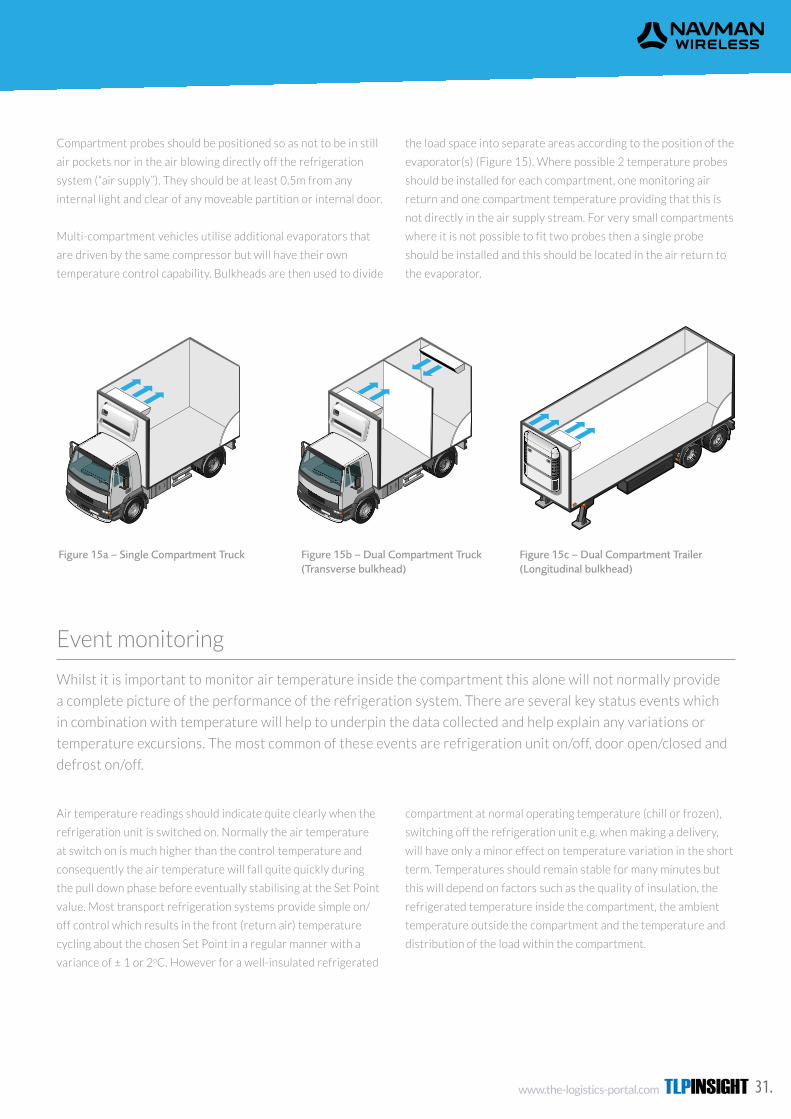
www.the-logistics-portal.com TLPINSIGHT 31.
Whilst it is important to monitor air temperature inside the compartment this alone will not normally provide
a complete picture of the performance of the refrigeration system. There are several key status events which
in combination with temperature will help to underpin the data collected and help explain any variations or
temperature excursions. The most common of these events are refrigeration unit on/off, door open/closed and
defrost on/off.
Event monitoring
Compartment probes should be positioned so as not to be in still
air pockets nor in the air blowing directly off the refrigeration
system (“air supply”). They should be at least 0.5m from any
internal light and clear of any moveable partition or internal door.
Multi-compartment vehicles utilise additional evaporators that
are driven by the same compressor but will have their own
temperature control capability. Bulkheads are then used to divide
Air temperature readings should indicate quite clearly when the
refrigeration unit is switched on. Normally the air temperature
at switch on is much higher than the control temperature and
consequently the air temperature will fall quite quickly during
the pull down phase before eventually stabilising at the Set Point
value. Most transport refrigeration systems provide simple on/
off control which results in the front (return air) temperature
cycling about the chosen Set Point in a regular manner with a
variance of ± 1 or 2oC. However for a well-insulated refrigerated
the load space into separate areas according to the position of the
evaporator(s) (Figure 15). Where possible 2 temperature probes
should be installed for each compartment, one monitoring air
return and one compartment temperature providing that this is
not directly in the air supply stream. For very small compartments
where it is not possible to fit two probes then a single probe
should be installed and this should be located in the air return to
the evaporator.
compartment at normal operating temperature (chill or frozen),
switching off the refrigeration unit e.g. when making a delivery,
will have only a minor effect on temperature variation in the short
term. Temperatures should remain stable for many minutes but
this will depend on factors such as the quality of insulation, the
refrigerated temperature inside the compartment, the ambient
temperature outside the compartment and the temperature and
distribution of the load within the compartment.
5.7 Event monitoring
5.7.1 Refrigeration unit on/off
Whilst it is important to monitor air temperature inside the compartment this alone will not normally provide a complete picture of the performance of the refrigeration system. There are several key status events which in combination with temperature will help to underpin the data collected and help explain any variations or temperature excursions. The most common of these events are refrigeration unit on/off, door open/closed and defrost on/off.
Air temperature readings should indicate quite clearly when the refrigeration unit is switched on. Normally the air temperature at switch on is much higher than the control temperature and consequently the air temperature will fall quite quickly during the pull down phase before eventually stabilising at the Set Point value. Most transport refrigeration systems provide simple on/off control which results in the front (return air) temperature cycling about the chosen Set Point in a regular manner with a variance of ± 1 or 2oC.
However for a well-insulated refrigerated compartment at normal operating temperature (chill or frozen), switching off the refrigeration unit e.g. when making a delivery, will have only a minor effect on temperature variation in the short term. Temperatures should remain stable for many minutes but this will depend on factors such as the quality of insulation, the refrigerated temperature inside the compartment, the ambient temperature outside the compartment and the temperature and distribution of the load within the compartment.
Knowing when the refrigeration unit is on or off is a valuable piece of information which can enhance the temperature data set in a number of ways. What happens if the driver switches the refrigeration unit off but forgets to switch it back on again, for example? Is it better to open the compartment door (to make a delivery) with the unit on or off? Should out of range temperature alerts be disabled when the unit is switched off (e.g. at the end of the day or weekend when the vehicle is out of service)?
It is normally possible to monitor the unit on/off state by simply picking up a feed from the unit on/off switch and connecting this to a relevant input on the temperature monitoring system hardware. It is recommended to do this whenever possible and for whatever type and size of vehicle is being monitored. However it is recommended to always consult the refrigeration system supplier for details of an appropriate connection point for an on/off signal.
Figure 15a – Single Compartment Truck Figure 15b – Dual Compartment Truck (Transverse bulkhead)
Figure 15c – Dual Compartment Trailer (Longitudinal bulkhead)
25
5.5 Thermal response and product simulation
5.6 Don’t just measure air temperature at a single point
EN standard 12830 (see section 3.1.3) specifies that the thermal response of a recorder with external sensor used for transport applications should be 10 minutes maximum. The response is defined as the time needed to reach 90% of a 20oC step change in air temperature with an air speed of 1m/s.
Many temperature monitoring systems just measure the air temperature in the air returning to the refrigeration unit. Some also include a probe that monitors the air supply blowing directly off the evaporator (“air supply”). However the main reason for air temperature monitoring in refrigerated vehicles is to confirm that temperature controlled air is circulating throughout the compartment. This requires that compartment probes are fitted towards the rear of the loadspace as described in section 5.1.
24 The ultimate guide to effective temperature control in refrigerated transport
Most data recorders utilise probes with a thermal response value of around 5 to 8 minutes. This permits appropriate air temperature measurement and also includes a certain amount of damping to provide correlation with the slower thermal response of the products that are being transported. Electronic damping, by including averaging of the temperature data during the recording interval, will also help to provide further correlation with the thermal response of the product itself.
In certain circumstances product simulators can also be used. These normally comprise a temperature sensor embedded in an inert medium of gel or plastic. Whilst these do have some advantages for multi-drop delivery regimes, particularly when the ambient temperature
is much higher than the compartment temperature, such devices can only really represent the thermal characteristics of a single type of product of a specific weight, packaged in a particular way. It is generally much better (and easier) to ensure that the product is loaded onto the vehicle at the correct temperature and then surrounded by air at the correct temperature rather than trying to simulate the thermal characteristics of the product.
The combination of air temperature readings, from suitably damped air temperature sensors plus the provision of out of range air temperature alerts, which incorporate a suitable time delay, is considered to be the most effective temperature monitoring regime. See section 5.8 for details of temperature alert monitoring.
Compartment probes should be positioned so as not to be in still air pockets nor in the air blowing directly off the refrigeration system (“air supply”). They should be at least 0.5m from any internal light and clear of any moveable partition or internal door.
Multi-compartment vehicles utilise additional evaporators that are driven by the same compressor but will have their own temperature control capability. Bulkheads are then used to divide the load space into separate areas according to the position of the evaporator(s) (Figure 15).
Where possible 2 temperature probes should be installed for each compartment, one monitoring air return and one compartment temperature providing that this is not directly in the air supply stream. For very small compartments where it is not possible to fit two probes then a single probe should be installed and this should be located in the air return to the evaporator.
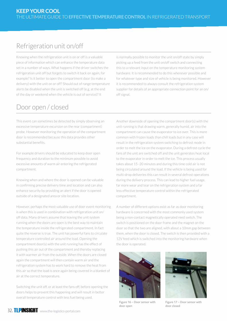
TLPINSIGHT www.the-logistics-portal.com32.
KEEP YOUR COOL THE ULTIMATE GUIDE TO EFFECTIVE TEMPERATURE CONTROL IN REFRIGERATED TRANSPORT
Refrigeration unit on/off
Door open / closed
Knowing when the refrigeration unit is on or off is a valuable
piece of information which can enhance the temperature data
set in a number of ways. What happens if the driver switches the
refrigeration unit off but forgets to switch it back on again, for
example? Is it better to open the compartment door (to make a
delivery) with the unit on or off? Should out of range temperature
alerts be disabled when the unit is switched off (e.g. at the end
of the day or weekend when the vehicle is out of service)? It
This event can sometimes be detected by simply observing an
excessive temperature excursion on the rear (compartment)
probe. However monitoring the operation of the compartment
door is recommended because this data provides other
substantial benefits.
For example drivers should be educated to keep door open
frequency and duration to the minimum possible to avoid
excessive amounts of warm air entering the refrigerated
compartment.
Knowing when and where the door is opened can be valuable
in confirming precise delivery time and location and can also
enhance security by providing an alert if the door is opened
outside of a designated area or site location.
However, perhaps the most valuable use of door event monitoring
is when this is used in combination with refrigeration unit on/
off data. Many drivers assume that leaving the unit system
running when the doors are open is the best way to maintain
the temperature inside the refrigerated compartment. In fact
quite the reverse is true. The unit has powerful fans to circulate
temperature controlled air around the load. Opening the
compartment door(s) with the unit running has the effect of
pushing this air out of the compartment and thereby replacing
it with warmer air from the outside. When the doors are closed
again the compartment will then contain warm air and the
refrigeration system has to work hard to remove the heat from
this air so that the load is once again being covered in a blanket of
air at the correct temperature.
Switching the unit off, or at least the fans off, before opening the
doors helps to prevent this happening and will result in better
overall temperature control with less fuel being used.
is normally possible to monitor the unit on/off state by simply
picking up a feed from the unit on/off switch and connecting
this to a relevant input on the temperature monitoring system
hardware. It is recommended to do this whenever possible and
for whatever type and size of vehicle is being monitored. However
it is recommended to always consult the refrigeration system
supplier for details of an appropriate connection point for an on/
off signal.
Another downside of opening the compartment door(s) with the
unit running is that drawing warm, generally humid, air into the
compartment can cause the evaporator to ice over. This is more
common with frozen loads than chill loads but in any case will
result in the refrigeration system switching to defrost mode in
order to melt the ice on the evaporator. During a defrost cycle the
fans of the unit are switched off and the unit generates heat local
to the evaporator in order to melt the ice. This process usually
takes about 15 -20 minutes and during this time cold air is not
being circulated around the load. If the vehicle is being used for
multi-drop deliveries this can result in several defrost operations
during the delivery process. This can lead to higher fuel usage,
far more wear and tear on the refrigeration system and a far
less effective temperature control within the refrigerated
compartment.
A number of different options exist as far as door monitoring
hardware is concerned with the most commonly used system
being a non-contact magnetically operated reed switch. The
switch is positioned on the door frame and the magnet on the
door so that the two are aligned, with about a 10mm gap between
them, when the door is closed. The switch is then provided with a
12V feed which is switched into the monitoring hardware when
the door is operated.
5.7.4 Monitoring refrigeration system specific data
5.8.1 Door alert
Some data management systems provide the capability to connect to the refrigeration unit micro-processor to extract specific detailed information. This can include temperature data and also information such as Set Point, unit run status (diesel or electric standby), hours run and unit engine alarm data. It is even possible through some
systems to operate the unit remotely by, for example, adjusting the Set Point value.
These systems can simplify fleet operation and allow refrigeration system maintenance schedules to be automatically generated. They are more ideally suited to very large fleets.
Alerts associated with compartment door operation are also a very useful feature. This would generally only work retrospectively for a stand-alone system, providing the transport manager with data to check length of door openings at delivery locations.
For a live telematics system the door alert can inform when a load is being delivered and alert in real time if the door is open for too long. This system can also provide warnings when doors are opened outside of designated delivery locations thereby enhancing load security.
5.8 Temperature Alert Monitoring
Most temperature monitoring systems include a mechanism to provide a warning when temperatures fall outside of acceptable limits. Alerts can normally be provided when the temperature deviates by a specific amount from a nominated value (typically the Set Point) or fall outside of an acceptable range.
For a stand-alone data logger system the alert can notify the driver of a potential problem and for a telematics system both the driver and the vehicle’s operation centre will be provided with warnings. There is then the option to carry out further checks on load condition and refrigeration system operation in order to decide on appropriate corrective action.
Alert monitoring can in some cases include the option to be triggered by a power state. This is normally the unit on state. This has the effect of enabling the alert when the refrigeration unit is operational and disabling the alert when the unit is switched off or the vehicle is otherwise not in use e.g. overnight or at weekends.
If unit on/off is not being monitored as part of the temperature application then care has to be taken when using out of range alerts since “false” alert messages will be generated when the unit is switched off at the end of the day and the temperature rises out of range.
It is also important to ensure that an adequate delay or “breach” time is allowed before a temperature alert is generated. The air temperature inside the refrigerated compartment cycles around the unit control temperature
(Set Point) value. Additionally whilst changes in air temperature are relatively quick, the temperature probe has a deliberately slower thermal response and the load in the refrigerated compartment is considerably slower to respond to temperature changes.
A meaningful alert breach time is in the order of 15-30 minutes. If the air temperature is out of range and has stayed out of range for this period of time it is safe to assume that there is a genuine problem that needs addressing. It is unlikely that the product quality or safety will have been compromised during a breach time of this magnitude.
Whilst it is possible to apply alerts to any of the temperature sensors being used to collect data it is prudent to apply alerts to the Rear or Compartment sensor rather than the Front or Air Return sensor. The Compartment temperature is generally more indicative of the temperature of the load and alerts will also be generated if air flow to the rear of the compartment is poor or restricted due to incorrect stowage of the load. In addition the Air Return temperature can vary considerably from the normal value during a defrost cycle and this could produce false alerts.
27
5.7.2 Door open / closed
26 The ultimate guide to effective temperature control in refrigerated transport
This event can sometimes be detected by simply observing an excessive temperature excursion on the rear (compartment) probe. However monitoring the operation of the compartment door is recommended because this data provides other substantial benefits.
For example drivers should be educated to keep door open frequency and duration to the minimum possible to avoid excessive amounts of warm air entering the refrigerated compartment.
Knowing when and where the door is opened can be valuable in confirming precise delivery time and location and can also enhance security by providing an alert if the door is opened outside of a designated area or site location.
However, perhaps the most valuable use of door event monitoring is when this is used in combination with refrigeration unit on/off data. Many drivers assume that leaving the unit system running when the doors are open is the best way to maintain the temperature inside the refrigerated compartment. In fact quite the reverse is true. The unit has powerful fans to circulate temperature controlled air around the load. Opening the compartment door(s) with the unit running has the effect of pushing this air out of the compartment and thereby replacing it with warmer air from the outside. When the doors are closed again the compartment will then contain warm air and the refrigeration system has to work hard to remove the heat from this air so that the load is once again being covered in a blanket of air at the correct temperature.
Switching the unit off, or at least the fans off, before opening the doors helps to prevent this happening and will result in better overall temperature control with less fuel being used.
Another downside of opening the compartment door(s) with the unit running is that drawing warm,
generally humid, air into the compartment can cause the evaporator to ice over. This is more common with frozen loads than chill loads but in any case will result in the refrigeration system switching to defrost mode in order to melt the ice on the evaporator. During a defrost cycle the fans of the unit are switched off and the unit generates heat local to the evaporator in order to melt the ice. This process usually takes about 15 -20 minutes and during this time cold air is not being circulated around the load. If the vehicle is being used for multi-drop deliveries this can result in several defrost operations during the delivery process. This can lead to higher fuel usage, far more wear and tear on the refrigeration system and a far less effective temperature control within the refrigerated compartment.
A number of different options exist as far as door monitoring hardware is concerned with the most commonly used system being a non-contact magnetically operated reed switch. The switch is positioned on the door frame and the magnet on the door so that the two are aligned, with about a 10mm gap between them, when the door is closed. The switch is then provided with a 12V feed which is switched into the monitoring hardware when the door is operated.
Figure 16 – Door sensor with door open
Figure 17 – Door sensor with door closed
5.7.3 Defrost
This event can usually be detected by a sudden rise and fall in air return temperature with corresponding small or unnoticeable change in compartment temperature.
It is therefore not so essential to monitor this event separately, indeed on some refrigeration systems it can be difficult to connect to the control system in order to pick up a signal representative of defrost operation.
Unless there is a specific requirement to monitor defrost on/off it should be considered that this event is an option rather than a definite requirement.
Examples of temperature data graphs showing door open/closed, refrigeration unit on/off and the effects of defrost operation are shown in section 6.

www.the-logistics-portal.com TLPINSIGHT 33.
Defrost
Monitoring refrigeration system specific data
This event can usually be detected by a sudden rise and fall in air
return temperature with corresponding small or unnoticeable
change in compartment temperature.
It is therefore not so essential to monitor this event separately,
indeed on some refrigeration systems it can be difficult to connect
Some data management systems provide the capability to connect
to the refrigeration unit micro-processor to extract specific
detailed information. This can include temperature data and also
information such as Set Point, unit run status (diesel or electric
standby), hours run and unit engine alarm data. It is even possible
through some systems to operate the unit remotely by, for
to the control system in order to pick up a signal representative of
defrost operation.
Unless there is a specific requirement to monitor defrost on/off
it should be considered that this event is an option rather than a
definite requirement.
example, adjusting the Set Point value.
These systems can simplify fleet operation and allow refrigeration
system maintenance schedules to be automatically generated.
They are more ideally suited to very large fleets.
Most temperature monitoring systems include a mechanism to provide a warning when temperatures fall
outside of acceptable limits. Alerts can normally be provided when the temperature deviates by a specific
amount from a nominated value (typically the Set Point) or fall outside of an acceptable range.
Temperature Alert Monitoring
For a stand-alone data logger system the alert can notify the
driver of a potential problem and for a telematics system both the
driver and the vehicle’s operation centre will be provided with
warnings. There is then the option to carry out further checks
on load condition and refrigeration system operation in order to
decide on appropriate corrective action.
Alert monitoring can in some cases include the option to be
triggered by a power state. This is normally the unit on state. This
has the effect of enabling the alert when the refrigeration unit
is operational and disabling the alert when the unit is switched
off or the vehicle is otherwise not in use e.g. overnight or at
weekends.
If unit on/off is not being monitored as part of the temperature
application then care has to be taken when using out of range
alerts since “false” alert messages will be generated when the unit
is switched off at the end of the day and the temperature rises out
of range.
It is also important to ensure that an adequate delay or “breach”
time is allowed before a temperature alert is generated. The air
temperature inside the refrigerated compartment cycles around
the unit control temperature (Set Point) value. Additionally whilst
changes in air temperature are relatively quick, the temperature
probe has a deliberately slower thermal response and the load in
the refrigerated compartment is considerably slower to respond
to temperature changes.
A meaningful alert breach time is in the order of 15- 30 minutes.
If the air temperature is out of range and has stayed out of range
for this period of time it is safe to assume that there is a genuine
problem that needs addressing. It is unlikely that the product
quality or safety will have been compromised during a breach
time of this magnitude.
Whilst it is possible to apply alerts to any of the temperature
sensors being used to collect data it is prudent to apply alerts to
the Rear or Compartment sensor rather than the Front or Air
Return sensor. The Compartment temperature is generally more
indicative of the temperature of the load and alerts will also be
generated if air flow to the rear of the compartment is poor or
restricted due to incorrect stowage of the load. In addition the Air
Return temperature can vary considerably from the normal value
during a defrost cycle and this could produce false alerts.
TLPINSIGHT www.the-logistics-portal.com34.
KEEP YOUR COOL THE ULTIMATE GUIDE TO EFFECTIVE TEMPERATURE CONTROL IN REFRIGERATED TRANSPORT
Door alert
Method
Alerts associated with compartment door operation are
also a very useful feature. This would generally only work
retrospectively for a stand-alone system, providing the transport
manager with data to check length of door openings at delivery
locations.
The Verification Check should preferably be carried out within
± 5oC of the temperature of use of the refrigerated compartment.
For chilled applications the optimum test temperature is 0oC.
There are two temperature checking methods available, one of
which is for use at 0oC (the ‘Ice Point’ check) and the other for use
For a live telematics system the door alert can inform when a
load is being delivered and alert in real time if the door is open
for too long. This system can also provide warnings when doors
are opened outside of designated delivery locations thereby
enhancing load security.
at any other temperature. In each case the procedure is to check
the sensors one at a time and record the sensor serial number and
the results of the check on a Verification Certificate.
The verification of the accuracy of an installed temperature measurement system consists of performing
a check that determines that the combination of the measurement device and its temperature sensor(s),
measure within specified limits of error.
Temperature Accuracy Verification
Equipment Required
It is recommended that the verification procedure is undertaken
in accordance with the requirements of European Standard EN
13486 (Periodic Verification). This is a ‘checking’ procedure
only, since most measurement devices do not include the facility
for user adjustments to either the measuring instrument or its
sensor(s). If the temperature measurement system fails to meet
the required accuracy of measurement then either the measuring
instrument or its sensor(s) or both should be replaced.
The frequency of the verification check depends on the
requirements of the user, taking account of the manufacturer’s
recommendations. If the temperature measuring system is
mounted on a vehicle which is subjected to an annual or periodic
maintenance inspection then the verification of the system should
be done at the same time.
• A Reference Thermometer with a valid calibration certificate, traceable to National Standards, with an
accuracy of 0.2 °C at the required temperature.
• A supply of tie wraps.
• Ice, water and vacuum flask (for ‘Ice Point’ check only).
• A supply of blank Verification Certificates for completion during the procedure.
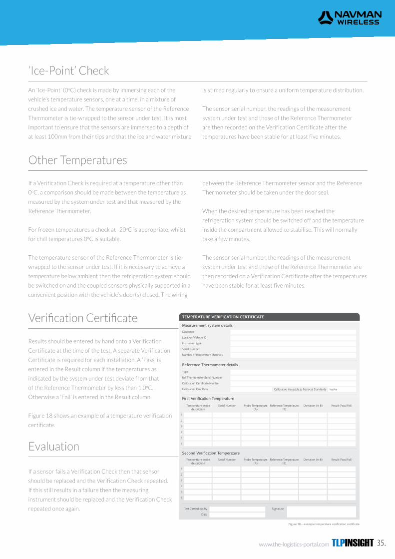
www.the-logistics-portal.com TLPINSIGHT 35.
‘Ice-Point’ Check
Other Temperatures
Verification Certificate
Evaluation
An ‘Ice-Point’ (0oC) check is made by immersing each of the
vehicle’s temperature sensors, one at a time, in a mixture of
crushed ice and water. The temperature sensor of the Reference
Thermometer is tie-wrapped to the sensor under test. It is most
important to ensure that the sensors are immersed to a depth of
at least 100mm from their tips and that the ice and water mixture
If a Verification Check is required at a temperature other than
0oC, a comparison should be made between the temperature as
measured by the system under test and that measured by the
Reference Thermometer.
For frozen temperatures a check at -20oC is appropriate, whilst
for chill temperatures 0oC is suitable.
The temperature sensor of the Reference Thermometer is tie-
wrapped to the sensor under test. If it is necessary to achieve a
temperature below ambient then the refrigeration system should
be switched on and the coupled sensors physically supported in a
convenient position with the vehicle’s door(s) closed. The wiring
Results should be entered by hand onto a Verification
Certificate at the time of the test. A separate Verification
Certificate is required for each installation. A ‘Pass’ is
entered in the Result column if the temperatures as
indicated by the system under test deviate from that
of the Reference Thermometer by less than 1.0oC.
Otherwise a ‘Fail’ is entered in the Result column.
Figure 18 shows an example of a temperature verification
certificate.
If a sensor fails a Verification Check then that sensor
should be replaced and the Verification Check repeated.
If this still results in a failure then the measuring
instrument should be replaced and the Verification Check
repeated once again.
is stirred regularly to ensure a uniform temperature distribution.
The sensor serial number, the readings of the measurement
system under test and those of the Reference Thermometer
are then recorded on the Verification Certificate after the
temperatures have been stable for at least five minutes.
between the Reference Thermometer sensor and the Reference
Thermometer should be taken under the door seal.
When the desired temperature has been reached the
refrigeration system should be switched off and the temperature
inside the compartment allowed to stabilise. This will normally
take a few minutes.
The sensor serial number, the readings of the measurement
system under test and those of the Reference Thermometer are
then recorded on a Verification Certificate after the temperatures
have been stable for at least five minutes.
6.0 Examples of Temperature Data
Transport refrigeration systems are intended to maintain the temperature of properly pre-cooled and thermally stable product.
Transport refrigeration systems are not designed to refrigerate (extract heat from) a warm product i.e. a product with a temperature several degrees warmer than the required control temperature inside the refrigerated
compartment. When a warm product is loaded into the compartment the refrigeration system will work much harder but the product temperature is unlikely to change during a normal journey period. This will waste fuel.
A - Signifies a warm product.
The unit is controlling at around -20oC (front probe cycling evenly about this temperature) but the rear probe is stable at around -14oC.
B – Signifies a product at the correct temperature.
The temperature of the front and rear are almost identical with lower frequency of cycling (longer period between cycles) than example A. This signifies that the product loaded is thermally stable at a temperature close to -20oC.
6.1 Warm Product
20.0
10.0
0.0
-10.0
-20.0
-30.0
Tem
pera
ture
Cel
sius
(0 C)
04:00 08:00 12:00 16:00 20:00 00:00
TimeFront Rear
Fridge
Door
Open/On Close/Off
AB
Figure 19 – Typical graph of temperature when transporting a warm product
31
5.9.5 (continued)
30 The ultimate guide to effective temperature control in refrigerated transport
TEMPERATURE VERIFICATION CERTIFICATE
Measurement system details
Reference Thermometer details
First Verification Temperature
Second Verification Temperature
Customer
Location/Vehicle ID
Instrument type
Serial Number
Number of temperature channels
Type
Ref Thermometer Serial Number
Calibration Certificate Number
Calibration Due Date
Test Carried out by
Date
Signature
Calibration traceable to National Standards
Figure 18 – example temperature verification certificate
Yes/No
Temperature probe description
Temperature probe description
Serial Number
Serial Number
Probe Temperature (A)
Probe Temperature (A)
Reference Temperature (B)
Reference Temperature (B)
Deviation (A-B)
Deviation (A-B)
Result (Pass/Fail)
Result (Pass/Fail)
1
2
3
4
5
6
1
2
3
4
5
6
5.9.6 Evaluation
If a sensor fails a Verification Check then that sensor should be replaced and the Verification Check repeated. If this still results in a failure then the measuring
instrument should be replaced and the Verification Check repeated once again.
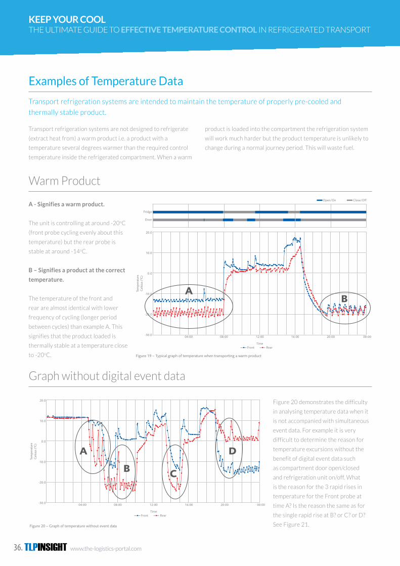
TLPINSIGHT www.the-logistics-portal.com36.
KEEP YOUR COOL THE ULTIMATE GUIDE TO EFFECTIVE TEMPERATURE CONTROL IN REFRIGERATED TRANSPORT
Transport refrigeration systems are intended to maintain the temperature of properly pre-cooled and
thermally stable product.
Examples of Temperature Data
Transport refrigeration systems are not designed to refrigerate
(extract heat from) a warm product i.e. a product with a
temperature several degrees warmer than the required control
temperature inside the refrigerated compartment. When a warm
product is loaded into the compartment the refrigeration system
will work much harder but the product temperature is unlikely to
change during a normal journey period. This will waste fuel.
Warm Product
Graph without digital event data
A - Signifies a warm product.
The unit is controlling at around -20oC
(front probe cycling evenly about this
temperature) but the rear probe is
stable at around -14oC.
B – Signifies a product at the correct
temperature.
The temperature of the front and
rear are almost identical with lower
frequency of cycling (longer period
between cycles) than example A. This
signifies that the product loaded is
thermally stable at a temperature close
to -20oC.
Figure 20 demonstrates the difficulty
in analysing temperature data when it
is not accompanied with simultaneous
event data. For example it is very
difficult to determine the reason for
temperature excursions without the
benefit of digital event data such
as compartment door open/closed
and refrigeration unit on/off. What
is the reason for the 3 rapid rises in
temperature for the Front probe at
time A? Is the reason the same as for
the single rapid rise at B? or C? or D?
See Figure 21.
6.0 Examples of Temperature Data
Transport refrigeration systems are intended to maintain the temperature of properly pre-cooled and thermally stable product.
Transport refrigeration systems are not designed to refrigerate (extract heat from) a warm product i.e. a product with a temperature several degrees warmer than the required control temperature inside the refrigerated
compartment. When a warm product is loaded into the compartment the refrigeration system will work much harder but the product temperature is unlikely to change during a normal journey period. This will waste fuel.
A - Signifies a warm product.
The unit is controlling at around -20oC (front probe cycling evenly about this temperature) but the rear probe is stable at around -14oC.
B – Signifies a product at the correct temperature.
The temperature of the front and rear are almost identical with lower frequency of cycling (longer period between cycles) than example A. This signifies that the product loaded is thermally stable at a temperature close to -20oC.
6.1 Warm Product
20.0
10.0
0.0
-10.0
-20.0
-30.0
Tem
pera
ture
Cel
sius
(0 C)
04:00 08:00 12:00 16:00 20:00 00:00
TimeFront Rear
Fridge
Door
Open/On Close/Off
AB
Figure 19 – Typical graph of temperature when transporting a warm product
31
5.9.5 (continued)
30 The ultimate guide to effective temperature control in refrigerated transport
TEMPERATURE VERIFICATION CERTIFICATE
Measurement system details
Reference Thermometer details
First Verification Temperature
Second Verification Temperature
Customer
Location/Vehicle ID
Instrument type
Serial Number
Number of temperature channels
Type
Ref Thermometer Serial Number
Calibration Certificate Number
Calibration Due Date
Test Carried out by
Date
Signature
Calibration traceable to National Standards
Figure 18 – example temperature verification certificate
Yes/No
Temperature probe description
Temperature probe description
Serial Number
Serial Number
Probe Temperature (A)
Probe Temperature (A)
Reference Temperature (B)
Reference Temperature (B)
Deviation (A-B)
Deviation (A-B)
Result (Pass/Fail)
Result (Pass/Fail)
1
2
3
4
5
6
1
2
3
4
5
6
5.9.6 Evaluation
If a sensor fails a Verification Check then that sensor should be replaced and the Verification Check repeated. If this still results in a failure then the measuring
instrument should be replaced and the Verification Check repeated once again.
6.3 Graph with digital event data
Fridge
Door
Open/On Close/Off
20.0
10.0
0.0
-10.0
-20.0
-30.0
Tem
pera
ture
Cel
sius
(0 C)
04:00 08:00 12:00 16:00 20:00 00:00
TimeFront Rear
A
B C
D
Figure 21 – Graph of temperature data showing simultaneous event data
Figure 21 shows exactly the same data as shown in Figure 20 but with the added information provided by digital monitoring event data for unit on/off and door open/closed. It is now possible to determine that:-
A – The repeated rises in temperature of the front probe are due to defrost cycles. The reason for the numerous defrosts is that the compartment door has been left opened with the unit running. This causes warm (humid) air to be drawn over the unit evaporator resulting in rapid ice build-up. The defrost cycle is instigated to melt this ice on the evaporator. The Rear air temperature stays fairly stable whilst the Front air temperature increases by 10oC or more before the unit returns to normal operation. Multiple rapid defrosts result in extreme wear and tear on the refrigeration system and much higher fuel consumption. It is possible to prevent this from happening by switching the unit off when the compartment doors are open.
B – Front and Rear temperature both rise because the unit is switched off and the door is opened. When the unit is switched back on it has been set to a 2 compartment operation, controlling Frozen at the front and Chill at the rear. Note that before the unit is switched off here that there is a 10oC difference between the Front and Rear temperatures suggesting that the product is warm. Loading a warm product will further increase the number of defrost cycles that take place.
C & D – Doors are closed and unit is on so any rapid rise and fall in temperature is probably a defrost. Note that for D the unit has now been changed so that the Front compartment is Chill and the Rear Compartment Frozen.
33
6.2 Graph without digital event data
32 The ultimate guide to effective temperature control in refrigerated transport
Figure 20 demonstrates the difficulty in analysing temperature data when it is not accompanied with simultaneous event data. For example it is very difficult to determine the reason for temperature excursions without the benefit of digital event data such as compartment door open/closed and refrigeration unit on/off.
What is the reason for the 3 rapid rises in temperature for the Front probe at time A?
Is the reason the same as for the single rapid rise at B? or C? or D?
See Figure 21.
20.0
10.0
0.0
-10.0
-20.0
-30.0
Tem
pera
ture
Cel
sius
(0 C)
04:00 08:00 12:00 16:00 20:00 00:00
TimeFront Rear
A
B C
D
Figure 20 – Graph of temperature without event data

www.the-logistics-portal.com TLPINSIGHT 37.
Figure 21 shows exactly the same data as shown in Figure 20 but
with the added information provided by digital monitoring event
data for unit on/off and door open/ closed. It is now possible to
determine that:
A – The repeated rises in temperature of the front probe are
due to defrost cycles. The reason for the numerous defrosts is
that the compartment door has been left opened with the unit
running. This causes warm (humid) air to be drawn over the
unit evaporator resulting in rapid ice build-up. The defrost cycle
is instigated to melt this ice on the evaporator. The Rear air
temperature stays fairly stable whilst the Front air temperature
increases by 10oC or more before the unit returns to normal
operation. Multiple rapid defrosts result in extreme wear and tear
on the refrigeration system and much higher fuel consumption. It
is possible to prevent this from happening by switching the unit
off when the compartment doors are open.
B – Front and Rear temperature both rise because the unit is
switched off and the door is opened. When the unit is switched
back on it has been set to a 2 compartment operation, controlling
Frozen at the front and Chill at the rear. Note that before the
unit is switched off here that there is a 10oC difference between
the Front and Rear temperatures suggesting that the product is
warm. Loading a warm product will further increase the number
of defrost cycles that take place.
C & D – Doors are closed and unit is on so any rapid rise and fall
in temperature is probably a defrost. Note that for D the unit has
now been changed so that the Front compartment is Chill and the
Rear Compartment Frozen.
Graph without digital event data6.3 Graph with digital event data
Fridge
Door
Open/On Close/Off
20.0
10.0
0.0
-10.0
-20.0
-30.0
Tem
pera
ture
Cel
sius
(0 C)
04:00 08:00 12:00 16:00 20:00 00:00
TimeFront Rear
A
B C
D
Figure 21 – Graph of temperature data showing simultaneous event data
Figure 21 shows exactly the same data as shown in Figure 20 but with the added information provided by digital monitoring event data for unit on/off and door open/closed. It is now possible to determine that:-
A – The repeated rises in temperature of the front probe are due to defrost cycles. The reason for the numerous defrosts is that the compartment door has been left opened with the unit running. This causes warm (humid) air to be drawn over the unit evaporator resulting in rapid ice build-up. The defrost cycle is instigated to melt this ice on the evaporator. The Rear air temperature stays fairly stable whilst the Front air temperature increases by 10oC or more before the unit returns to normal operation. Multiple rapid defrosts result in extreme wear and tear on the refrigeration system and much higher fuel consumption. It is possible to prevent this from happening by switching the unit off when the compartment doors are open.
B – Front and Rear temperature both rise because the unit is switched off and the door is opened. When the unit is switched back on it has been set to a 2 compartment operation, controlling Frozen at the front and Chill at the rear. Note that before the unit is switched off here that there is a 10oC difference between the Front and Rear temperatures suggesting that the product is warm. Loading a warm product will further increase the number of defrost cycles that take place.
C & D – Doors are closed and unit is on so any rapid rise and fall in temperature is probably a defrost. Note that for D the unit has now been changed so that the Front compartment is Chill and the Rear Compartment Frozen.
33
6.2 Graph without digital event data
32 The ultimate guide to effective temperature control in refrigerated transport
Figure 20 demonstrates the difficulty in analysing temperature data when it is not accompanied with simultaneous event data. For example it is very difficult to determine the reason for temperature excursions without the benefit of digital event data such as compartment door open/closed and refrigeration unit on/off.
What is the reason for the 3 rapid rises in temperature for the Front probe at time A?
Is the reason the same as for the single rapid rise at B? or C? or D?
See Figure 21.
20.0
10.0
0.0
-10.0
-20.0
-30.0
Tem
pera
ture
Cel
sius
(0 C)
04:00 08:00 12:00 16:00 20:00 00:00
TimeFront Rear
A
B C
D
Figure 20 – Graph of temperature without event data
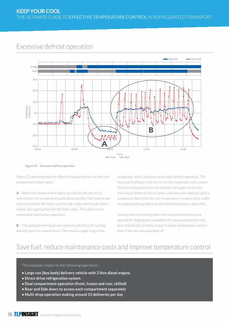
TLPINSIGHT www.the-logistics-portal.com38.
KEEP YOUR COOL THE ULTIMATE GUIDE TO EFFECTIVE TEMPERATURE CONTROL IN REFRIGERATED TRANSPORT
Excessive defrost operation
Save fuel, reduce maintenance costs and improve temperature control
Figure 22 demonstrates the effect of operating the unit with the
compartment doors open.
A – When the compartment doors are closed and the unit is
switched on the temperature pulls down quickly. The front probe
cycles around its Set Point and the rear probe which pulls down
slower also approaches the Set Point value. This seems to be
reasonably satisfactory operation.
B – The compartment doors are opened with the unit running
and left open for several hours. The result is rapid icing of the
evaporator which produces automatic defrost operation. The
localised heating to melt the ice on the evaporator coils causes
the front temperature to rise and then fall again as the unit
tries to pull down to the set point value once the defrost cycle is
completed. Note that the rear temperature remains fairly stable
throughout this period at an elevated temperature above 0oC.
Leaving the unit running when the compartment doors are
opened for loading and unloading will cause unnecessary fuel
burn and almost certainly result in worse temperature control
than if the unit was switched off.
6.5 Save fuel, reduce maintenance costs and improve temperature control
The direct drive refrigeration system is powered by the vehicle engine so the engine has to be running for the unit to work. Ignition on/off is monitored as indicative of unit on/off. The driver normally leaves the engine/unit running at the point of delivery because he believes that this helps to keep the compartments refrigerated.
Figure 23 shows that the ignition is left on, with engine running, throughout the day. Temperatures vary wildly with numerous excursions above 10oC in the rear (chilled) compartment and temperatures rising up to -10oC in
the front (frozen) compartment. Also leaving the engine running at each stop (and therefore driving the unit) means highly excessive idling of the vehicle engine.
Continued over
This example relates to the following operation:-
• Large van (box body) delivery vehicle with 2 litre diesel engine.
• Direct drive refrigeration system
• Dual compartment operation (front, frozen and rear, chilled)
• Rear and Side doors to access each compartment separately
• Multi-drop operation making around 15 deliveries per day
20.0
10.0
0.0
-10.0
-20.0
-30.0
Tem
pera
ture
Cel
sius
(0 C)
00:00 01:00 02:00 03:00 04:00 5:00 06:00 07:00 08:00 09:00 10:00 11:00
TimeFront Rear
Side Door
Rear Door
Ignition
Open/On Close/Off
Figure 23 – Data for direct drive unit with engine left running at point of delivery
3534 The ultimate guide to effective temperature control in refrigerated transport
6.4 Excessive defrost operation
Figure 22 demonstrates the effect of operating the unit with the compartment doors open.
A – When the compartment doors are closed and the unit is switched on the temperature pulls down quickly. The front probe cycles around its Set Point and the rear probe which pulls down slower also approaches the Set Point value. This seems to be reasonably satisfactory operation.
B – The compartment doors are opened with the unit running and left open for several hours. The result is rapid icing of the evaporator which produces automatic
defrost operation. The localised heating to melt the ice on the evaporator coils causes the front temperature to rise and then fall again as the unit tries to pull down to the set point value once the defrost cycle is completed. Note that the rear temperature remains fairly stable throughout this period at an elevated temperature above 0oC.
Leaving the unit running when the compartment doors are opened for loading and unloading will cause unnecessary fuel burn and almost certainly result in worse temperature control than if the unit was switched off.
30.0
20.0
10.0
0.0
-10.0
-20.0
-30.0
Tem
pera
ture
Cel
sius
(0 C)
00:00 04:00 08:00 12:00 16:00
TimeFront Rear
Fridge
Door
Open/On Close/Off
A
B
Figure 22 – Excessive defrost operation
This example relates to the following operation:-
• Large van (box body) delivery vehicle with 2 litre diesel engine.
• Direct drive refrigeration system
• Dual compartment operation (front, frozen and rear, chilled)
• Rear and Side doors to access each compartment separately
• Multi-drop operation making around 15 deliveries per day

www.the-logistics-portal.com TLPINSIGHT 39.
Figure 23 shows that the ignition
is left on, with engine running,
throughout the day. Temperatures
vary wildly with numerous
excursions above 10oC in the
rear (chilled) compartment and
temperatures rising up to -10oC in
the front (frozen) compartment. Also
leaving the engine running at each
stop (and therefore driving the unit)
means highly excessive idling of the
vehicle engine.
Figure 24 shows that the driver has been
instructed to switch the ignition/unit off
at every delivery point. As a result the
chill temperatures cycle nicely around
5oC and frozen temperatures remain
below -20oC. This clearly demonstrates
far superior temperature control when the
unit is switched off at the delivery point. In
addition the idle time has been reduced by
about 2 hours over an approximately 8 hour
delivery period. Assuming a fuel burn during
idling for this vehicle of 1.25 litres per hour
and a net fuel cost of £1.00 per litre this
represents a saving of approximately £2.50
per day or, assuming a 20 days per month
delivery operation, around £50.00 per
month per vehicle.
6.5 Save fuel, reduce maintenance costs and improve temperature control
The direct drive refrigeration system is powered by the vehicle engine so the engine has to be running for the unit to work. Ignition on/off is monitored as indicative of unit on/off. The driver normally leaves the engine/unit running at the point of delivery because he believes that this helps to keep the compartments refrigerated.
Figure 23 shows that the ignition is left on, with engine running, throughout the day. Temperatures vary wildly with numerous excursions above 10oC in the rear (chilled) compartment and temperatures rising up to -10oC in
the front (frozen) compartment. Also leaving the engine running at each stop (and therefore driving the unit) means highly excessive idling of the vehicle engine.
Continued over
This example relates to the following operation:-
• Large van (box body) delivery vehicle with 2 litre diesel engine.
• Direct drive refrigeration system
• Dual compartment operation (front, frozen and rear, chilled)
• Rear and Side doors to access each compartment separately
• Multi-drop operation making around 15 deliveries per day
20.0
10.0
0.0
-10.0
-20.0
-30.0
Tem
pera
ture
Cel
sius
(0 C)
00:00 01:00 02:00 03:00 04:00 5:00 06:00 07:00 08:00 09:00 10:00 11:00
TimeFront Rear
Side Door
Rear Door
Ignition
Open/On Close/Off
Figure 23 – Data for direct drive unit with engine left running at point of delivery
3534 The ultimate guide to effective temperature control in refrigerated transport
6.4 Excessive defrost operation
Figure 22 demonstrates the effect of operating the unit with the compartment doors open.
A – When the compartment doors are closed and the unit is switched on the temperature pulls down quickly. The front probe cycles around its Set Point and the rear probe which pulls down slower also approaches the Set Point value. This seems to be reasonably satisfactory operation.
B – The compartment doors are opened with the unit running and left open for several hours. The result is rapid icing of the evaporator which produces automatic
defrost operation. The localised heating to melt the ice on the evaporator coils causes the front temperature to rise and then fall again as the unit tries to pull down to the set point value once the defrost cycle is completed. Note that the rear temperature remains fairly stable throughout this period at an elevated temperature above 0oC.
Leaving the unit running when the compartment doors are opened for loading and unloading will cause unnecessary fuel burn and almost certainly result in worse temperature control than if the unit was switched off.
30.0
20.0
10.0
0.0
-10.0
-20.0
-30.0
Tem
pera
ture
Cel
sius
(0 C)
00:00 04:00 08:00 12:00 16:00
TimeFront Rear
Fridge
Door
Open/On Close/Off
A
B
Figure 22 – Excessive defrost operation
7.0 Conclusions and Recommendations
7.1 Ensure that the vehicle and refrigeration system are properly specified
The fundamental requirement of good refrigerated vehicle design is that the combination of the insulation properties of the vehicle and the capacity of the refrigeration system should be capable of overcoming the anticipated heat gain inside the refrigerated compartment. Heat gain will be through the insulated bodywork (good insulation will minimise this but cannot prevent heat transmission entirely), through opening the compartment doors when loading/unloading and from the product itself (although this should be minimal if the product is loaded at the correct temperature).
Operators should consult with their chosen bodybuilder and refrigeration system manufacturer to ensure that operational requirements are clearly understood and
that a vehicle type and refrigeration system capable of meeting or exceeding these requirements are specified.
7.2 Operate the vehicle in the best possible way
No matter how good the design and manufacture of the refrigerated vehicle, nor how suited it is for the application concerned, it will not overcome bad practice encountered in the day-to-day operation of the vehicle.
37
The critical MUST DO stages in refrigerated vehicle operation are:-
• Pre-cool compartment and defrost if necessary
• Switch off the refrigeration unit before opening the compartment door
• Insert the product/load at the correct temperature
• Distribute the load properly
• Surround the load with air at the correct temperature
• Minimise the time that the compartment door spends open at the point of delivery
In addition:-
• Load on pallets wherever possible as this will improve overall air flow
• Do not load above the red (maximum height) load line
• Never mix different temperature loads (e.g. chill and frozen) in a single compartment
Drivers and warehouse staff responsible for loading/unloading should be trained to understand and comply with these requirements some of which may appear to be counter-intuitive.
6.5 Save fuel, reduce maintenance costs and improve temperature control (continued)
36 The ultimate guide to effective temperature control in refrigerated transport
10.0
0.0
-10.0
-20.0
-30.0
Tem
pera
ture
Cel
sius
(0 C)
00:00 01:00 02:00 03:00 04:00 5:00 06:00 07:00 08:00 09:00 10:00 11:00
TimeFront Rear
Side Door
Rear Door
Ignition
Open/On Close/Off
Figure 24 - Data for direct drive unit with engine switch off at point of delivery
Figure 24 shows that the driver has been instructed to switch the ignition/unit off at every delivery point. As a result the chill temperatures cycle nicely around 5oC and frozen temperatures remain below -20oC. This clearly demonstrates far superior temperature control when the unit is switched off at the delivery point.
In addition the idle time has been reduced by about 2 hours over an approximately 8 hour delivery period.
Assuming a fuel burn during idling for this vehicle of 1.25 litres per hour and a net fuel cost of £1.00 per litre this represents a saving of approximately £2.50 per day or, assuming a 20 days per month delivery operation, around £50.00 per month per vehicle.
The overall result is
• Improved temperature control
• A substantial saving in fuel cost
• A 25% reduction in refrigeration system operating time
• Less wear and tear on vehicle and refrigeration system
• Increased vehicle and refrigeration unit service interval
The overall result is
• Improved temperature control
• A substantial saving in fuel cost
• A 25% reduction in refrigeration system operating time
• Less wear and tear on vehicle and refrigeration system
• Increased vehicle and refrigeration unit service interval
The direct drive refrigeration system is powered by the vehicle engine so the engine has to be running for the
unit to work. Ignition on/off is monitored as indicative of unit on/off. The driver normally leaves the engine/unit
running at the point of delivery because he believes that this helps to keep the compartments refrigerated.
TLPINSIGHT www.the-logistics-portal.com40.
KEEP YOUR COOL THE ULTIMATE GUIDE TO EFFECTIVE TEMPERATURE CONTROL IN REFRIGERATED TRANSPORT
The fundamental requirement of good refrigerated vehicle design is that the combination of the insulation
properties of the vehicle and the capacity of the refrigeration system should be capable of overcoming the
anticipated heat gain inside the refrigerated compartment. Heat gain will be through the insulated bodywork
(good insulation will minimise this but cannot prevent heat transmission entirely), through opening the
compartment doors when loading/ unloading and from the product itself (although this should be minimal if the
product is loaded at the correct temperature).
No matter how good the design and manufacture of the refrigerated vehicle, nor how suited it is for the
application concerned, it will not overcome bad practice encountered in the day-to-day operation of the
vehicle.
Using a data monitoring system will allow compilation of data to satisfy HACCP and Due Diligence
requirements. A wide range of systems are available but it is strongly recommended that any system used
includes monitoring of air temperature at several points within the loadspace plus monitoring of critical events
such as door open/closed and refrigeration unit on/off.
Conclusions and Recommendations
Ensure that the vehicle and refrigeration system are properly specified
Operate the vehicle in the best possible way
Monitor temperature and events
Operators should consult with their chosen bodybuilder and
refrigeration system manufacturer to ensure that operational
requirements are clearly understood and that a vehicle type
The incremental cost for adding event monitoring will usually be
relatively small. The enhanced dataset so produced will be far
more beneficial in monitoring the refrigeration system as a whole
in order to optimise performance and make tangible savings in
and refrigeration system capable of meeting or exceeding these
requirements are specified.
operational cost.
To simplify data analysis and focus on areas that need
improvement and which can generate savings, utilise a monitoring
The critical MUST DO stages in refrigerated vehicle
operation are:-
• Pre-cool compartment and defrost if necessary
• Switch off the refrigeration unit before opening the
compartment door
• Insert the product/load at the correct temperature
• Distribute the load properly
• Surround the load with air at the correct
temperature
• Minimise the time that the compartment door
spends open at the point of delivery
In addition:-
• Load on pallets wherever possible as this will improve
overall air flow
• Do not load above the red (maximum height) load line
• Never mix different temperature loads (e.g. chill and
frozen) in a single compartment
Drivers and warehouse staff responsible for loading/
unloading should be trained to understand and comply
with these requirements some of which may appear to
be counter-intuitive.
www.the-logistics-portal.com TLPINSIGHT 41.
To maintain the performance of a refrigerated vehicle it is essential that the refrigeration system is serviced
regularly by a competent organisation. The vehicle bodywork should also be inspected for any damage and this
should be repaired as quickly as possible. Water ingress through damaged bodywork will severely reduce the
insulation properties and cause local “hot-spots”.
Whichever type of data recording system is used it is important that records are kept for at least 12 months. In
the case of pharmaceuticals this may need to be extended further, in some cases up to 5 years.
Navman Wireless would like to thank the following for their invaluable help in the compilation of this guide:-
• Maurice Young Consulting
• The Food Storage and Distribution Federation
• Transfrigoroute UK
• Thermo King UK
• Marshall Fleet Solutions Ltd
• Cambridge Refrigeration Technology Ltd
• Frigoblock UK Ltd
• TM Electronics (UK) Ltd
Check equipment function on a regular basis
Maintain records and use the data to drive improvements
Acknowledgments
Temperature monitoring equipment should also be checked for
accuracy on an annual basis or as otherwise specified by the
equipment manufacturer.
Vehicle owners should maintain a dialogue with their data
monitoring system provider and if necessary solicit their help
on how to use the data being collected to make improvements.
Operators should not assume that because they have always
operated in a particular way that there is no alternative. Making
simple operational changes can often deliver improvements which
will result in a substantial return on investment.
Improved temperature control should yield fewer load rejections
and less product wastage, saving costs and enhancing customer
service levels. Optimising temperature control can also have
system that can provide live out of range alerts. This might be
a temperature alert, a door open alert or a combination of both
such things. An early warning of a potential problem can help
minimise wastage or spoilage of the product.
When combined with positional data (e.g. on a combined tracking/
temperature monitoring system), knowledge of the frequency,
duration and location of door openings can be a highly useful
feature to help improve temperature control and thereby
maintain product temperature. When data concerning door
operation is reported live it can also have a direct beneficial
effect on load security which can also help to reduce insurance
premiums.
a marked improvement of fuel consumption. Automatic data
collection saves on administration costs associated with HACCP
and Due Diligence compliance, plus an improved risk profile
should reduce load liability insurance costs.
Improving temperature control and increasing operational
efficiency can result in numerous tangible benefits and enable
direct and indirect savings to be made. The confidence that this
can bring should place the vehicle operator in a better position to
win respect from customers and help to secure more business.

TLPINSIGHT www.the-logistics-portal.com42.
RELIANCE DEPENDSON PREVENTATIVE MAINTENANCEBY BRIAN KOHR, PRESIDENT AND CEO
Whi
te P
aper
It is evident when reviewing the Good Distribution Practice guidelines that there has been
a shift in emphasis towards Risk Management in the distribution of temperaturesensitive
pharmaceuticals. Whether it's the publication of the recent EU guidance, the revisions from
USP or the PDA's technical report 58, there can be no mistaking one thing - shippers and
manufacturers are ultimately responsible for examining their supply chains using a 'risk-based'
approach.
Let's be clear what risk is by using the definition from the International Conference on
Harmonization [ICH] and its Q9 document:
Risk is defined as 'The combination of the probability of occurrence of harm and the severity of
that harm'.
Harm is defined as 'Damage to health, including the damage that can occur from loss of product
quality or availability'.
Hazard is defined as 'The potential source of harm'.
This might sound straightforward but a 'risk-based' approach warrants an in-depth analysis
including an evaluation of the elapsed time since the validation of the current temperature-
sensitive shipping and packaging solutions. Some suppliers have utilized the same solutions
for decades although technology, regulations and guidelines have continued to evolve. The
production process also has challenges related to contract manufacturing, multiple vendors and
locations that are distant from the point of sale. Identifying the potential sources of harm to
a product being transported through several temperature zones, multiple transit points and a
variety of modes can be an exacting task.
During all of these stages, patient safety is of course paramount, but we also recognize that the
pressures for more cost-effective supply chains can be immense. It is not surprising therefore,
that managing risk has attracted a more aggressive regulatory stance both at GMP and GDP
levels. It is also a good explanation for the additional call from regulators for written agreements
between manufacturers and their logistics supply chain partners.
Risk Management is designed to assist organizations in safeguarding the quality and supply of
product to customers and ultimately the end user. It is about anticipating hazards and controlling
risk through an ongoing process of risk awareness, reduction and I or acceptance, and review.
This approach can help justify needed improvements and investments, and prevent both
potential problems for customers [e.g. product recalls or even patient harm] and loss of business.
Moreover, though implementing risk management might well be initially linked to a single
product or supply chain process, it should not be considered as a one time action. Adopting a
'culture' of quality risk management that is embedded in the processes and procedures used
by manufacturers and their supply chain partners will have long-term benefits. The level of
awareness to risk will inevitably improve and provide a platform for continuous improvement.
Adopting a culture of
quality risk management will provide a platform for continous improvement.

www.the-logistics-portal.com TLPINSIGHT 43.
Issue 07 - 2014 WWW.THE-LOGISTICS-PORTAL.COM TLPTHE LOGISTICS PORTAL MAGAZINE
www.CSafeGlobal.com [email protected]
In their recently revised GDP guidelines (2013/C 343/01) the European Commission has a relatively simple statement
regarding the distribution of temperature-sensitive products:
"'Risk assessment of delivery routes should be used to determine where temperature controls are required'."
The first part of any 'route qualification' process should start with the creation of a Qualification Master Plan that sets out
stages, processes and responsibilities. And sometimes, simplest is best - use the power of your internal team and your external
Logistics suppliers to initially map out every distribution and handling stage for your product. Additional detail should be added
considering both the physical and documentary processes and conditions.
Through the various transport modes, identify those steps and handover points that are most at risk. Look at this from a
seasonally adjusted temperature environment and quality control processes, and consider how to mitigate the risk to your
product. Is the route and transport supplier capable of managing that risk? Is there a contingency plan in place? Are there written
agreements and SOP's in place? What importance is placed on process control and process measurements versus measuring end
results when it is too Late to prevent an unsuccessful shipment?
Identifying the physical steps and risk points is important to maintain the efficacy of any drug. But what about qualifying your
supplier of thermal protection and having more than one validated solution to further mitigate the risk of failure? Just like good
cold chain management starts with the manufacturer, having a range of validated solutions 'ready-to-use' will provide you with
the means to maintain that correct thermal protection, regardless of the distribution challenges.
The market for both passive and active solutions has expanded over recent years and there is now a comprehensive array
of suppliers. Shippers should validate their choice of solution providers by predetermined criteria:
• Availability - is the solution always available at seasonal peaks and internationally?
• Solution range - does the supplier provide both active and passive solutions?
• Performance - have their solutions been validated to your needs?
• Re-usability - does the supplier have a program for packaging re-use?
• Custom-built solutions - new/different products may need new solutions and thus, can the supplier respond to new
requirements?
All of these considerations will provide you with a far more comprehensive risk assessment of your supply chain and provide a
built-in confidence that a product will not be compromised regardless of whether it has been transported 5 miles or 5000 miles.
It also creates contingency plans that can really make a difference to successful transportation.
Risk management should not be centered only upon the choice of which route, which logistic provider and which type of
packaging solution to use. Key to minimizing risk is to qualify more than one thermal shipping solution and preferably utilizing a
provider that can offer both active and passive solutions to meet the specific needs of your product.

44.
THE LOGISTICS PORTAL MAGAZINE
WWW.THE-LOGISTICS-PORTAL.COM Issue 07 - 2014TLP
A sustainable solution for temperature
controlled urban distribution
TLPINSIGHT www.the-logistics-portal.com
www.the-logistics-portal.com TLPINSIGHT 45.
Issue 07 - 2014 WWW.THE-LOGISTICS-PORTAL.COM TLPTHE LOGISTICS PORTAL MAGAZINE
Complete peace of mind for your pharmaceutical and healthcare shipments
[email protected] | www.cargolux.com
Flying with careIt is essential that the quality and integrity of your high value and temperature sensitive pharmaceutical and healthcare products is protected throughout the entire transportation cycle.
Backed by our fleet of advanced Boeing 747-8 and 747-400 freighter aircraft and a brand-new purpose-built 3,000 m2 warehouse facility with temperature- and humidity-controlled environments at our Luxembourg hub, we offer you speedy, reliable and tailored solutions to meet your sophisticated needs.
On and off ground, your pharmaceutical products are in the best hands with our dedicated team of highly trained and experienced professionals. And, as you would expect from true pioneers, we are the first GDP certified airline in the world.
+2°C to +8°C +15°C to +25°C
Advert to change?

TLPINSIGHT www.the-logistics-portal.com46.
THE LOGISTICS PORTAL MAGAZINE
WWW.THE-LOGISTICS-PORTAL.COM Issue 07 - 2014TLPGrowing environmental pressure for change
Since the late 1930s, transporting temperature sensitive
goods by road and rail depended almost entirely on fossil
fuels and high global warming potential (GWP) refrigerants to
maintain cargo at the optimum temperature. Today, internal
combustion engines have become quieter, more fuel efficient
and cleaner. Nevertheless the dependence on fossil fuel and
hydrofluorocarbon (HFC) refrigerants remains.
Regulations and social pressure have dramatically changed
the way transporters operate in the European Union (EU).
Environmental sustainability is a top objective of legislators
determined to phase out high GWP refrigerants, control exhaust
emissions and limit noise in densely populated areas.
An alternative to fossil fuels and HFC refrigerants
For the past 15 years, the manufacturer of transport temperature
control systems, Thermo King, has focused on developing a
solution that would meet the future need for an alternative to the
fossil fuel or HFC technologies on which the transport industry
has depended for so long. In the 1930s, Thermo King pioneered
transport temperature control and they have remained the
leading innovator in this industry ever since.
How the system works
The company’s alternative approach, which remains unique in
transport refrigeration today, involves the use of recovered and
commercially available liquid carbon dioxide (R-744) in an indirect
open-cycle system. Unlike other ‘cryogenic’ approaches which
spray the refrigerant directly into the load space, the Thermo
King CryoTech range uses fin-and-tube evaporators as heat
exchangers through which the R-744 flows, absorbing heat from
the load before it is vented to the outside of the vehicle.
The recovered R-744 is stored under pressure in a vacuum
insulated tank under the chassis of the truck or articulated trailer.
It flows to the remote evaporators, one of which is installed in
each compartment allowing up to three temperatures on one
vehicle. An electronic expansion valve managed by the electric
control module regulates the flow of liquid through each
evaporator thereby varying their cooling capacity to match the
demands of the load and maintain a steady temperature.
Just like conventional HFC refrigerants, the liquid R-744 changes
state (into a gas) as its pressure drops on leaving the expansion
valve and rapidly absorbs heat energy in the process. A regulator
keeps gas pressures above the critical 5.5 bar point to avoid the
formation of dry ice in the evaporator. After the liquid R-744
vaporizes causing the temperature to lower in the insulated box,
the vapor is vented outside the box through an exhaust muffler
to minimize noise. This is important with regard to the health and
safety of operators and goods.
A system defined by what it lacks
The system is more notable for what it lacks rather than what
it possesses. The truck or trailer unit is cooled with virtually no
operating noise without the use of diesel engine, compressor, or
HFC refrigerant.
The recovered R-744 in the Thermo King CryoTech systems is
obtained as a by-product from industrial processes that would
otherwise have been released into the atmosphere. As such there
are no new carbon dioxide emissions during operation of the
CryoTech system.
Operating costs similar to diesel
The cost of operating a CryoTech unit over its lifecycle is broadly
comparable to that of an equivalent conventional diesel powered
unit, although specific applications may favor one or the other.
The initial cost of the unit is likely to be slightly higher, due to
current low manufacturing volumes. This is offset by its longer
service life due to its long life components and fewer “wear”
items.
Cooling performance and noise
It has been proven that CryoTech evaporators deliver significantly
more cooling capacity than their diesel equivalent at both fresh
and frozen box temperatures. Pull down of an empty box can be
up to four times faster with R-744, making it an excellent choice
for distribution operations with a high number of door openings.
With more countries considering the introduction of noise limits
on evening and night deliveries – following the example of the
PIEK standard in the Netherlands - urban distribution operations
wanting to take advantage of low traffic volumes need a vehicle
that can perform at 60 dBA or less. All the CryoTech units are
PIEK tested and compliant offering sound levels up to 90% lower
than a standard diesel unit.
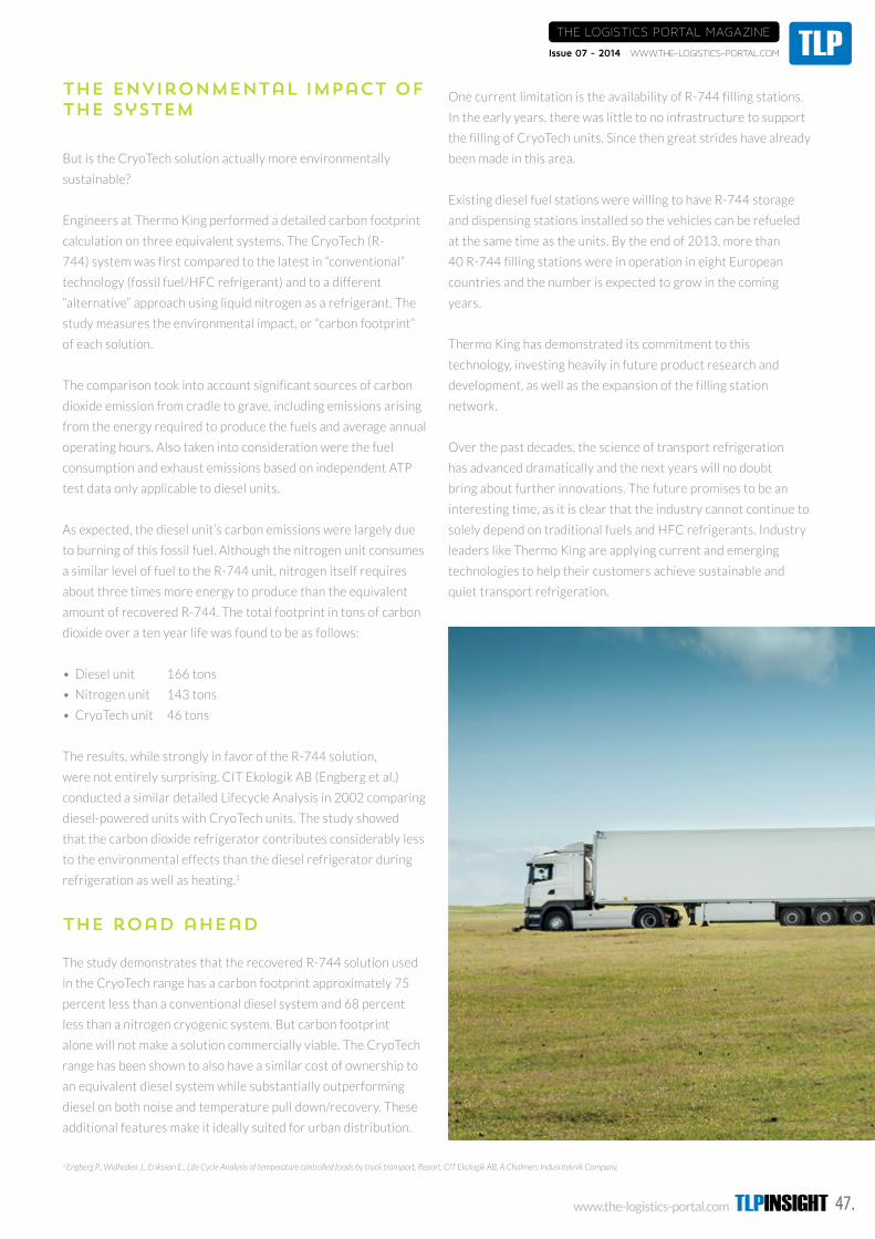
www.the-logistics-portal.com TLPINSIGHT 47.
Issue 07 - 2014 WWW.THE-LOGISTICS-PORTAL.COM TLPTHE LOGISTICS PORTAL MAGAZINE
The environmental impact of the system
But is the CryoTech solution actually more environmentally
sustainable?
Engineers at Thermo King performed a detailed carbon footprint
calculation on three equivalent systems. The CryoTech (R-
744) system was first compared to the latest in “conventional”
technology (fossil fuel/HFC refrigerant) and to a different
“alternative” approach using liquid nitrogen as a refrigerant. The
study measures the environmental impact, or “carbon footprint”
of each solution.
The comparison took into account significant sources of carbon
dioxide emission from cradle to grave, including emissions arising
from the energy required to produce the fuels and average annual
operating hours. Also taken into consideration were the fuel
consumption and exhaust emissions based on independent ATP
test data only applicable to diesel units.
As expected, the diesel unit’s carbon emissions were largely due
to burning of this fossil fuel. Although the nitrogen unit consumes
a similar level of fuel to the R-744 unit, nitrogen itself requires
about three times more energy to produce than the equivalent
amount of recovered R-744. The total footprint in tons of carbon
dioxide over a ten year life was found to be as follows:
• Diesel unit 166 tons
• Nitrogen unit 143 tons
• CryoTech unit 46 tons
The results, while strongly in favor of the R-744 solution,
were not entirely surprising. CIT Ekologik AB (Engberg et al.)
conducted a similar detailed Lifecycle Analysis in 2002 comparing
diesel-powered units with CryoTech units. The study showed
that the carbon dioxide refrigerator contributes considerably less
to the environmental effects than the diesel refrigerator during
refrigeration as well as heating.1
The road ahead
The study demonstrates that the recovered R-744 solution used
in the CryoTech range has a carbon footprint approximately 75
percent less than a conventional diesel system and 68 percent
less than a nitrogen cryogenic system. But carbon footprint
alone will not make a solution commercially viable. The CryoTech
range has been shown to also have a similar cost of ownership to
an equivalent diesel system while substantially outperforming
diesel on both noise and temperature pull down/recovery. These
additional features make it ideally suited for urban distribution.
One current limitation is the availability of R-744 filling stations.
In the early years, there was little to no infrastructure to support
the filling of CryoTech units. Since then great strides have already
been made in this area.
Existing diesel fuel stations were willing to have R-744 storage
and dispensing stations installed so the vehicles can be refueled
at the same time as the units. By the end of 2013, more than
40 R-744 filling stations were in operation in eight European
countries and the number is expected to grow in the coming
years.
Thermo King has demonstrated its commitment to this
technology, investing heavily in future product research and
development, as well as the expansion of the filling station
network.
Over the past decades, the science of transport refrigeration
has advanced dramatically and the next years will no doubt
bring about further innovations. The future promises to be an
interesting time, as it is clear that the industry cannot continue to
solely depend on traditional fuels and HFC refrigerants. Industry
leaders like Thermo King are applying current and emerging
technologies to help their customers achieve sustainable and
quiet transport refrigeration.
1 Engberg P., Widheden J., Eriksson E., Life Cycle Analysis of temperature controlled foods by truck transport, Report, CIT Ekologik AB, A Chalmers Indusriteknik Company.
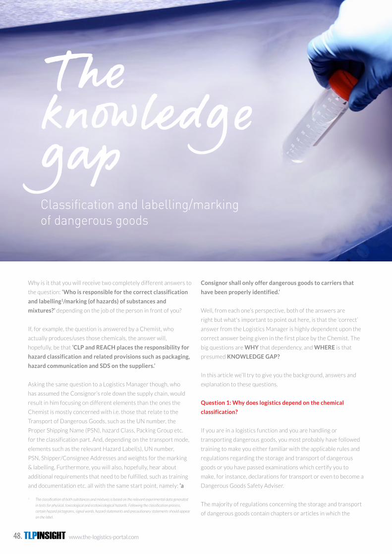
TLPINSIGHT www.the-logistics-portal.com48.
Why is it that you will receive two completely different answers to
the question: ‘Who is responsible for the correct classification
and labelling1/marking (of hazards) of substances and
mixtures?’ depending on the job of the person in front of you?
If, for example, the question is answered by a Chemist, who
actually produces/uses those chemicals, the answer will,
hopefully, be that ‘CLP and REACH places the responsibility for
hazard classification and related provisions such as packaging,
hazard communication and SDS on the suppliers.’
Asking the same question to a Logistics Manager though, who
has assumed the Consignor’s role down the supply chain, would
result in him focusing on different elements than the ones the
Chemist is mostly concerned with i.e. those that relate to the
Transport of Dangerous Goods, such as the UN number, the
Proper Shipping Name (PSN), hazard Class, Packing Group etc.
for the classification part. And, depending on the transport mode,
elements such as the relevant Hazard Label(s), UN number,
PSN, Shipper/Consignee Addresses and weights for the marking
& labelling. Furthermore, you will also, hopefully, hear about
additional requirements that need to be fulfilled, such as training
and documentation etc. all with the same start point, namely: ‘a
1 Theclassificationofbothsubstancesandmixturesisbasedontherelevantexperimentaldatagenerated
intestsforphysical,toxicologicalandecotoxicologicalhazards.Followingtheclassificationprocess,
certain hazard pictograms, signal words, hazard statements and precautionary statements should appear
on the label.
The knowledge gap Classification and labelling/marking of dangerous goods
Consignor shall only offer dangerous goods to carriers that
have been properly identified.’
Well, from each one’s perspective, both of the answers are
right but what's important to point out here, is that the ‘correct’
answer from the Logistics Manager is highly dependent upon the
correct answer being given in the first place by the Chemist. The
big questions are WHY that dependency, and WHERE is that
presumed KNOWLEDGE GAP?
In this article we’ll try to give you the background, answers and
explanation to these questions.
Question 1: Why does logistics depend on the chemical
classification?
If you are in a logistics function and you are handling or
transporting dangerous goods, you most probably have followed
training to make you either familiar with the applicable rules and
regulations regarding the storage and transport of dangerous
goods or you have passed examinations which certify you to
make, for instance, declarations for transport or even to become a
Dangerous Goods Safety Adviser.
The majority of regulations concerning the storage and transport
of dangerous goods contain chapters or articles in which the
www.the-logistics-portal.com TLPINSIGHT 49.
Issue 07 - 2014 WWW.THE-LOGISTICS-PORTAL.COM TLPTHE LOGISTICS PORTAL MAGAZINE
classification of dangerous goods is described. The scope of this
classification material is to explain to the user how he/she can
determine in which of the 9 hazard classes a substance/mixture or
article qualifies to be assigned and, if applicable, in which division,
packing group or compatibility group within that class.
By now you are probably thinking how you should be able to
do these tests in your warehouse? Indeed if you look through
the requirements there is no way you are able to perform these
test(s) if you do not have a laboratory environment including all
the equipment and trained staff.
Here is where the Safety Data Sheet (SDS) comes into the
picture! The SDS provides the results of the testing and
classification procedure performed by the Chemist under
prescribed GHS criteria. Many of those criteria are already based
on the ‘UN Model Regulations for Transport of Dangerous Goods,
Manual of Tests and Criteria’ and related legal instruments (ADR,
RID, ADN, IMDG Code and ICAO TI).
Thus, in the SDS, the primary use of which is for workplace
users, you should be able to find all the relevant testing and
other official information, including the transport classification,
regarding a specific substance, mixture or article2 grouped under
the following 16 sections:
SECTION 1: Identification of the substance/mixture
and of the company/undertaking
SECTION 2: Hazards identification
SECTION 3: Composition/information on ingredients
SECTION 4: First aid measures
SECTION 5: Firefighting measures
SECTION 6: Accidental release measures
SECTION 7: Handling and storage
SECTION 8: Exposure controls/personal protection
SECTION 9: Physical and chemical properties
SECTION 10: Stability and reactivity
SECTION 11: Toxicological information
SECTION 12: Ecological information
SECTION 13: Disposal considerations
SECTION 14: Transport information
SECTION 15: Regulatory information
SECTION 16: Other information
Ideally, all the information needed for a Consignor, when different
to the manufacturer3, who wishes to verify for himself the
correctness of the existent classification in order to properly
prepare a shipment for a substance/mixture or article according
to the requirements of the transport regulations, should be found
in these Sections whereby Section 3, 9, 11 and 12 contain the
most vital information.
Because regulations are highly prescriptive, if someone follows
the correct steps and, where needed, uses the Precedence of
Hazards Table correctly, (almost) nothing can go wrong, he/she
will end up with the same classification results prescribed under
Section 14 of the SDS, being:
14.1. UN number
14.2. UN proper shipping name
14.3. Transport hazard class(es)
14.4. Packing group
14.5. Environmental hazards
14.6. Special precautions for user
14.7. Transport in bulk according to Annex II of
MARPOL73/78 and the IBC Code
So, why not take the shortcut, just look at Section 14 and job done
for the Consignor, he can now continue with other work!
Question 2: Where is that presumed knowledge gap?
Here’s where the ‘tricky’ part starts! As indicated earlier, the
Consignor is the responsible (read ‘liable’) part in the logistics
chain. Thus, he should be able to make sure that the goods
offered are correctly packed, documented, marked and
labelled, simply because he has accepted the Consignor’s role
further down the supply chain. Though, this is practically possible
only when the information under section 14 is correct.
As we previously said, in cases where the Consignor is also
producer/manufacturer of the goods, both the classification of
the goods and the production of the SDS are in the same hands.
In this case, the Consignor has promptly available the information
on whatever he is shipping and has full control over all the aspects
involved in classification of the products.
It’s something else though when the Consignor is for instance a
trade organisation or a 3PL. In these cases the Consignor is no
longer the owner of the goods nor involved in the classification
process.
2 From marketing and/or logistical aspects it may in certain cases be useful for suppliers to have Safety Data
Sheets available for all substances and mixtures, including those for which there is no legal obligation to
provide an SDS. In such cases it may be desirable to indicate in the document that the substance or mixture
does not legally require an SDS to avoid unnecessary compliance and conformity issues arising. It is not
generally desirable to compile SDSs for articles [Ref ECHA]3 The initial responsibility for drawing up the safety data sheet falls on the manufacturer, importer or only
representative who should anticipate, so far as it is reasonably practicable, the uses to which the substance
or mixture may be put [Ref ECHA]
The big questions are WHY that dependency, and WHERE is that presumed
KNOWLEDGE GAP?

TLPINSIGHT www.the-logistics-portal.com50.
THE LOGISTICS PORTAL MAGAZINE
WWW.THE-LOGISTICS-PORTAL.COM Issue 07 - 2014TLP
Indeed, what actually happens in most cases, is that the
Consignor is relying on the information received from either the
owner or the manufacturer of the goods. A big question remains,
however. How can a Consignor verify, in a case where the
relevant information on the received SDS is lacking, whether the
classification under section 14 is correct?
Another widespread phenomenon, especially in the 3PL business,
is: the ‘gap in time before
becoming aware of updates’
regarding the classification,
and labelling. Regulations
require that each time
there’s an amendment for a
substance in CLP or when a
change is introduced in a mixture,
suppliers MUST reconsider the classification of that substance or
mixture. Also, they should promptly share the new information
with all the actors down the supply chain to allow them to fulfill
their obligations.
We have seen many examples of wrong SDSs delivered with
goods like an SDS for a liquid delivered with a solid substance
or an SDS based on old classification criteria where for instance
a flammable aerosol (Class 2) was still classified as Class 3
(Flammable liquids) for transport.
In the above cases the Consignor has a job to do to:
a. Train his staff to be accurate, attentive and knowledgeable
when dangerous goods are involved.
b. Have procedures in place with both owners and suppliers
of dangerous goods to make sure he receives accurate
information and also receives timely the updated versions of
SDSs once they become available.
The second factor affecting the knowledge gap is the knowledge
level of the ‘competent person’ and his/her capability to ensure
the consistency of the SDS. It is understood that any one single
person very rarely has extensive knowledge in all the fields
covered by an SDS. That’s why the regulations require that
‘Suppliers of substances and mixtures should be able to ensure
that such competent persons have received appropriate
training, including refresher training.’ Unfortunately, many
times and especially within smaller companies this role is also
assigned to (production/QC) Chemists who are not always
specialised in the transport classification of dangerous goods.
When you are involved in logistics, you know that regulations
regarding the transport of dangerous goods are changing
constantly. In some cases new UN numbers are added, in other
cases classification of certain substances are changing. Besides
that, we have differences between the different modes of
transport or, mainly for road, differences between countries.
Not every chemist will go through his list of SDSs to verify if
something has changed for Section 14 when a new regulation
is published. This leads not only to inaccurate SDSs but also to
liability issues for Consignors
as, in the end, they are
the responsible party for
the classification during
transport…
So, what to do?
Options and solutions
As indicated, the Owner/Manufacturer being Consignor as well
has the least problems as all is under one roof. The easiest way to
solve issues in this case, if there are any, is to make sure to use an
integrated software system in which both chemical management
and logistics are connected and where information is shared in
real time.
Meaning that when an SDS is changed, it will be published
immediately replacing the previous version. On the other hand, if
the transport regulations change, this will be indicated in the list
of SDS and forces an update to be processed by the Chemist.
Also a connection to the labelling for both chemical (GHS/CLP)
and transport (ADR/RID/IMDG/ICAO-TI/ADN/49CFR) should be
included to keep all marking and labelling for products updated.
For the Consignor not producing his own products, a similar
software system is recommended but used in a way where the
Owner/Supplier and Consignor have shared responsibilities
regarding information provision. This can be managed by making
firm agreements between the parties involved or using a third
party to make sure all information is as accurate as possible
at all times, keeping the parties involved updated on changed
documentation, regulations and labelling/marking.
Authors:
Herman Teering Managing Director
Panos Drougas, MSc Senior Chemical Consultant
DGM Software Development Group www.dgm-sdg.com
Train staff to be accurate, attentive and knowledgeable when dangerous goods are involved.

www.the-logistics-portal.com TLPINSIGHT 51.
Issue 07 - 2014 WWW.THE-LOGISTICS-PORTAL.COM TLPTHE LOGISTICS PORTAL MAGAZINE
//EVENTS
SMI COLD CHAIN DISTRIBUTION
December 2 - 3, 2014
London, United Kingdom
www.smi-online.co.uk/pharmaceuticals/uk/cold-chain-distribution
5TH ANNUAL COLD CHAIN MENA SUMMIT
January 11 - 14, 2015
Marriott Al Jaddaf, Dubai, United Arab Emirates
www.coldchainmiddleeast.comt
CLINICAL TRIAL SUPPLY EUROPE
January 21 - 23, 2014
Germany, Frankfurt
www.clinicalsupplyeurope.com
CLINICAL TRIAL SUPPLY EUROPE
January 26 - 29, 2014
Messe Frankfurt Venue GmbH, Frankfurt am Main, Germany
www.coolchaineurope.com
13TH COLD CHAIN GDP & TEMPERATURE MANAGEMENT LOGISTICS SUMMIT - CANADA
February 23 - 26, 2014
Hilton Montreal Bonaventure, Montreal, Canada
www.coldchainpharm.com
TLPINSIGHT www.the-logistics-portal.com52.
THE LOGISTICS PORTAL MAGAZINE
WWW.THE-LOGISTICS-PORTAL.COM Issue 07 - 2014TLP
@SMIPHARM
How to Register
www.coldchain-distribution.com
Current attendees include: • AAH Pharmaceuticals• Allergan• Alliance Healthcare• Eli Lilly
• F. Hoffmann-La Roche Ltd• Mundipharma• Priority Freight LHR Ltd• Public Health England
• Roche Pharmaceuticals• Sanofi-Aventis• Takeda Pharma
International
• The Saudi FDA• The Blood Transfusion
Centre of Slovenia• plus many more…
CHAIRS FOR 2014: Cheryl Blake, GDP Inspector, MHRA
Alan Dorling, Global Head - Pharmaceutical & LifeSciences, IAG Cargo
Andrea Gruber, Senior Manager, SpecialisedCargo, IATA
Tony Wright, Managing Director, Exelsius ColdChain Management
KEY SPEAKERS INCLUDE: • David Spillett, Business Development Manager,
Biopharm Services, World Courier• Tim Wood, Technical Service Manager, GSK• Gianpiero Lorusso, Supply Chain Manager, Merck Serono• Michelle Goodyear, QA Manager, AbbVie• Chris Wallace, Distribution Director, Genzyme• Didier Basseras, Vice President Global Head of Clinical Supplies
and Supply Chain, Sanofi Aventis R&D • Thomas Grubb, Manager, Cold Chain Strategy, American Airlines
SMi Presents the 9th Annual Conference on… 2nd - 3rd
DEC2014
Marriott Regents Park Hotel, London, UK
Cold Chain DistributionEnhance Temperature Management foran Efficient Supply Chain
Lead Sponsor: Sponsored by:
“In general, a very well organised event. Professional team and well executed” EVENT ATTENDEE 2013
a TCP Company
BOOK BY 30TH SEPTEMBER 2014 TO RECEIVE £300 OFF BOOK BY 31ST OCTOBER TO RECEIVE £100 OFF
Register online or fax your registration to +44 (0) 870 9090 712 or call +44 (0) 870 9090 711
World Courier will be hosting a unique and exciting evening dinner at the end ofDay 1. This event will be hosted at Gordon Ramsay’s Maze Restaurant and theRoutemaster will pick up from the Marriott Regents Park at 7.30pm. It promises to afantastic experience. Places are strictly limited, visit our website for further details.
Tuesday 2nd December Evening Dinner
Who should attendthis conference:
You should attend this event if you work in the PharmaceuticalIndustry with responsibilities in QualityAssurance, Quality Compliance,Regulatory, Supply Chain,Manufacturing, Packaging,Distribution, Operations.
Job titles include: • GMP Compliance Specialist• GMP Inspector • Director, Global Demand Planning
& Customer Operations • Director, Purchasing and
Distribution• General Manager, Distribution and
Logistics• Director, Regulatory Affairs,
Corporate GMP Officer• Head of Packaging• VP, Clinical Logistics• International Supplies Manager• Quality Assurance and Quality
Compliance Manager• Head of Corporate Supply Chain
Operations
Cold Chain Distribution Attendees2011-2013 by Industry Sector
PHARMACEUTICAL51%
REGULATORY 9%
SERVICES/PRODUCTSUPPLIERS 33%
ACADEMIA 7%
Cold Chain Distribution Attendees2011-2013 by Region
UK AND EUROPE 90%
USA 4%MIDDLE EAST 6%
Supported byPlatinum Media Partner
Silver Media Partner
BUSINESS BENEFITS FOR 2014:Benchmark and reflect on theimplementation of the GDP directive withcase studies from IATA, AbbVie and theDutch Health Care Inspectorate
Enhance your understanding of thechallenges of transport qualification fortemperature sensitive pharmaceuticalproducts with a round table discussion led byTony Wright, Managing Director, Exelsius ColdChain Management and an openingaddress from Alan Dorling, Global Head -Pharmaceutical & Life Sciences, IAG Cargo
Strengthen your supply chain throughmanagement and efficiency insights fromMerck Serono and Genzyme
A3Advert2 09/09/2014 16:47 Page 1

www.the-logistics-portal.com TLPINSIGHT 53.
Issue 07 - 2014 WWW.THE-LOGISTICS-PORTAL.COM TLPTHE LOGISTICS PORTAL MAGAZINE
@SMIPHARM
How to Register
www.coldchain-distribution.com
Current attendees include: • AAH Pharmaceuticals• Allergan• Alliance Healthcare• Eli Lilly
• F. Hoffmann-La Roche Ltd• Mundipharma• Priority Freight LHR Ltd• Public Health England
• Roche Pharmaceuticals• Sanofi-Aventis• Takeda Pharma
International
• The Saudi FDA• The Blood Transfusion
Centre of Slovenia• plus many more…
CHAIRS FOR 2014: Cheryl Blake, GDP Inspector, MHRA
Alan Dorling, Global Head - Pharmaceutical & LifeSciences, IAG Cargo
Andrea Gruber, Senior Manager, SpecialisedCargo, IATA
Tony Wright, Managing Director, Exelsius ColdChain Management
KEY SPEAKERS INCLUDE: • David Spillett, Business Development Manager,
Biopharm Services, World Courier• Tim Wood, Technical Service Manager, GSK• Gianpiero Lorusso, Supply Chain Manager, Merck Serono• Michelle Goodyear, QA Manager, AbbVie• Chris Wallace, Distribution Director, Genzyme• Didier Basseras, Vice President Global Head of Clinical Supplies
and Supply Chain, Sanofi Aventis R&D • Thomas Grubb, Manager, Cold Chain Strategy, American Airlines
SMi Presents the 9th Annual Conference on… 2nd - 3rd
DEC2014
Marriott Regents Park Hotel, London, UK
Cold Chain DistributionEnhance Temperature Management foran Efficient Supply Chain
Lead Sponsor: Sponsored by:
“In general, a very well organised event. Professional team and well executed” EVENT ATTENDEE 2013
a TCP Company
BOOK BY 30TH SEPTEMBER 2014 TO RECEIVE £300 OFF BOOK BY 31ST OCTOBER TO RECEIVE £100 OFF
Register online or fax your registration to +44 (0) 870 9090 712 or call +44 (0) 870 9090 711
World Courier will be hosting a unique and exciting evening dinner at the end ofDay 1. This event will be hosted at Gordon Ramsay’s Maze Restaurant and theRoutemaster will pick up from the Marriott Regents Park at 7.30pm. It promises to afantastic experience. Places are strictly limited, visit our website for further details.
Tuesday 2nd December Evening Dinner
Who should attendthis conference:
You should attend this event if you work in the PharmaceuticalIndustry with responsibilities in QualityAssurance, Quality Compliance,Regulatory, Supply Chain,Manufacturing, Packaging,Distribution, Operations.
Job titles include: • GMP Compliance Specialist• GMP Inspector • Director, Global Demand Planning
& Customer Operations • Director, Purchasing and
Distribution• General Manager, Distribution and
Logistics• Director, Regulatory Affairs,
Corporate GMP Officer• Head of Packaging• VP, Clinical Logistics• International Supplies Manager• Quality Assurance and Quality
Compliance Manager• Head of Corporate Supply Chain
Operations
Cold Chain Distribution Attendees2011-2013 by Industry Sector
PHARMACEUTICAL51%
REGULATORY 9%
SERVICES/PRODUCTSUPPLIERS 33%
ACADEMIA 7%
Cold Chain Distribution Attendees2011-2013 by Region
UK AND EUROPE 90%
USA 4%MIDDLE EAST 6%
Supported byPlatinum Media Partner
Silver Media Partner
BUSINESS BENEFITS FOR 2014:Benchmark and reflect on theimplementation of the GDP directive withcase studies from IATA, AbbVie and theDutch Health Care Inspectorate
Enhance your understanding of thechallenges of transport qualification fortemperature sensitive pharmaceuticalproducts with a round table discussion led byTony Wright, Managing Director, Exelsius ColdChain Management and an openingaddress from Alan Dorling, Global Head -Pharmaceutical & Life Sciences, IAG Cargo
Strengthen your supply chain throughmanagement and efficiency insights fromMerck Serono and Genzyme
A3Advert2 09/09/2014 16:47 Page 1

TLPINSIGHT www.the-logistics-portal.com54.
THE LOGISTICS PORTAL MAGAZINE
WWW.THE-LOGISTICS-PORTAL.COM Issue 07 - 2014TLP
//INDEX OF ADVERTISERS
IFC
5
7
9
12
45
52
IBC
OBC
CSAFE
Sofrigram
Softbox
Berlinger &Co AG
IATA
Cargolux
SMI
DGM
UPS
FOR ADVERTISING INFORMATION CONTACT:
Sales: [email protected]
Subscription: [email protected]
Dangerous Goods Management is all about
safety and minimizing risk. In air transpor tation,
staying compliant with all of the many rules
and regulations is not an easy task. However,
supported by DGOffi ce.net with its specifi c
modules for air transportation, it becomes a
clean cut operation. From Packing Instructions
to Shipper’s Declaration and ‘NOtifi cation TO
Caption’: it’s all in the software and highly
Safety fi rstin Dangerous Goods Management
DGM SDG A/S, Kokholm 3b, DK 6000 Kolding, +45 75 575 790,[email protected], www.dgoffi ce.net
automated where possible to save you time
and to reduce error rate to a minimum.
DGOffi ce.net was developed as an on-line
application, meaning you can access it anytime
from anywhere in the world. Alternatively,
run it as you see fi t: within your own network
or on a stand-alone computer.
014016_DGOffice_adv_203x280.indd 2 11-12-12 16:56

Issue 07 - 2014 WWW.THE-LOGISTICS-PORTAL.COM TLPTHE LOGISTICS PORTAL MAGAZINE
Dangerous Goods Management is all about
safety and minimizing risk. In air transpor tation,
staying compliant with all of the many rules
and regulations is not an easy task. However,
supported by DGOffi ce.net with its specifi c
modules for air transportation, it becomes a
clean cut operation. From Packing Instructions
to Shipper’s Declaration and ‘NOtifi cation TO
Caption’: it’s all in the software and highly
Safety fi rstin Dangerous Goods Management
DGM SDG A/S, Kokholm 3b, DK 6000 Kolding, +45 75 575 790,[email protected], www.dgoffi ce.net
automated where possible to save you time
and to reduce error rate to a minimum.
DGOffi ce.net was developed as an on-line
application, meaning you can access it anytime
from anywhere in the world. Alternatively,
run it as you see fi t: within your own network
or on a stand-alone computer.
014016_DGOffice_adv_203x280.indd 2 11-12-12 16:56