TL-PA4010P AV500 Powerline Adapter With AC Pass Through · One AV500 Powerline Adapter With AC Pass...
28
TL-PA4010P AV500 Powerline Adapter With AC Pass Through Rev: 1.0.0 1910010757
Transcript of TL-PA4010P AV500 Powerline Adapter With AC Pass Through · One AV500 Powerline Adapter With AC Pass...
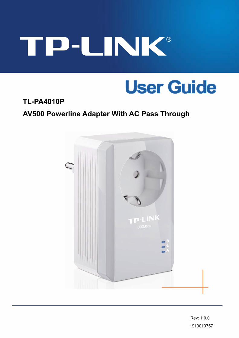
TL-PA4010P
AV500 Powerline Adapter With AC Pass Through
Rev: 1.0.0
1910010757

COPYRIGHT & TRADEMARKS
Specifications are subject to change without notice. is a registered trademark of TP-LINK TECHNOLOGIES CO., LTD. Other brands and product names are trademarks or registered trademarks of their respective holders.
No part of the specifications may be reproduced in any form or by any means or used to make any derivative such as translation, transformation, or adaptation without permission from TP-LINK TECHNOLOGIES CO., LTD. Copyright © 2012 TP-LINK TECHNOLOGIES CO., LTD. All rights reserved.
http://www.tp-link.com
FCC STATEMENT
This equipment has been tested and found to comply with the limits for a Class B digital device, pursuant to part 15 of the FCC Rules. These limits are designed to provide reasonable protection against harmful interference in a residential installation. This equipment generates, uses and can radiate radio frequency energy and, if not installed and used in accordance with the instructions, may cause harmful interference to radio communications. However, there is no guarantee that interference will not occur in a particular installation. If this equipment does cause harmful interference to radio or television reception, which can be determined by turning the equipment off and on, the user is encouraged to try to correct the interference by one or more of the following measures:
Reorient or relocate the receiving antenna.
Increase the separation between the equipment and receiver.
Connect the equipment into an outlet on a circuit different from that to which the receiver is connected.
Consult the dealer or an experienced radio/ TV technician for help.
This device complies with part 15 of the FCC Rules. Operation is subject to the following two conditions:
1) This device may not cause harmful interference.
2) This device must accept any interference received, including interference that may cause undesired operation.
Any changes or modifications not expressly approved by the party responsible for compliance could void the user’s authority to operate the equipment.
Note: The manufacturer is not responsible for any radio or TV interference caused by unauthorized modifications to this equipment. Such modifications could void the user’s authority to operate the equipment.
CE Mark Warning
This is a class B product. In a domestic environment, this product may cause radio interference, in which case the user may be required to take adequate measures.
Продукт сертифіковано згідно с правилами системи УкрСЕПРО на відповідність вимогам нормативних документів та вимогам, що передбачені чинними законодавчими актами України.

TP-LINK TECHNOLOGIES CO., LTD
Safety Information
When product has power button, the power button is one of the way to shut off the product; when there is no power button, the only way to completely shut off power is to disconnect the product or the power adapter from the power source.
Don’t disassemble the product, or make repairs yourself. You run the risk of electric shock and voiding the limited warranty. If you need service, please contact us.
Avoid water and wet locations.
This product can be used in the following countries:
AT BG BY CA CZ DE DK EE
ES FI FR GB GR HU IE IT
LT LV MT NL NO PL PT RO
RU SE SK TR UA

TP-LINK TECHNOLOGIES CO., LTD
DECLARATION OF CONFORMITY
For the following equipment:
Product Description: AV500 Powerline Adapter With AC Pass Through
Model No.: TL-PA4010P
Trademark: TP-LINK
We declare under our own responsibility that the above products satisfy all the technical regulations
applicable to the product within the scope of Council Directives:
Directives 2004 / 108 / EC, Directives 2006 / 95 / EC, Directives 2011/65/EU
The above product is in conformity with the following standards or other normative documents:
EN 55022:2010
EN 55024:2010
EN 61000-3-2:2006+A1:2009+A2:2009
EN 61000-3-3:2008
EN 50412-2-1:2005
EN60950-1:2006+A11:2009+A1:2010+A12:2011
The product carries the CE Mark
Person responsible for marking this declaration:
Yang Hongliang
Product Manager of International Business
Date of issue: 2012
TP-LINK TECHNOLOGIES CO., LTD.
Building 24 (floors 1, 3, 4, 5), and 28 (floors 1-4) Central Science and Technology Park, Shennan Rd, Nanshan, Shenzhen, China
CONTENTS
Package Contents......................................................................................... 1 Conventions .................................................................................................. 1 Chapter 1 Introduction ................................................................................. 2
1.1 System Requirement.......................................................................... 2 1.2 Important Safety Instructions ............................................................. 2 1.3 LED Indicator ..................................................................................... 3 1.4 Physical Interface............................................................................... 4
Chapter 2 Connecting Mechanism .............................................................. 6 2.1 Introduction ........................................................................................ 6 2.2 Connection Instruction ....................................................................... 6 2.3 Hardware Connection – Computer..................................................... 6 2.4 Hardware Connection – Internet ........................................................ 7
Chapter 3 Installing Management Utility..................................................... 9 Chapter 4 Using the Management Utility .................................................. 13
4.1 Status ............................................................................................... 13 4.1.1 Set Local Device’s Network Name......................................... 14
4.2 Network............................................................................................ 14 4.2.1 Rename the Remote Device/Enter Password........................ 15 4.2.2 Add Device ............................................................................. 16
4.3 Advanced ......................................................................................... 17 4.4 System ............................................................................................. 17
4.4.1 Upgrade Firmware ................................................................. 18 4.4.2 Reset Device.......................................................................... 19 4.4.3 Set All Devices’ Network Name.............................................. 19
Chapter 5 Advanced Feature: How to Use the Pair Buttons ................... 20 5.1 Pair (Secure with 128 bits-AES)....................................................... 20 5.2 Set Up a Secured Powerline AV Network with the Pair Button ........ 20
Appendix A: Troubleshooting.................................................................... 22
TL-PA4010P AV500 Powerline Adapter With AC Pass Through
1
Package Contents The AV500 Powerline Adapter With AC Pass Through package contains the following items:
One AV500 Powerline Adapter With AC Pass Through (There are two powerline adapters in Starter Kit)
One RJ-45 Cable (There are two RJ-45 Cables in Starter Kit)
One Quick Installation Guide
One Resource CD (Management Utility and User Guide)
Note:
Make sure that the package contains the above items. If any of the above items are damaged or missing, please contact your dealer immediately.
Conventions The powerline adapter or AV500 Powerline Adapter With AC Pass Through mentioned in this guide stands for TL-PA4010P AV500 Powerline Adapter With AC Pass Through without any explanation.
TL-PA4010P AV500 Powerline Adapter With AC Pass Through
2
Chapter 1 Introduction This device is an AV500 Powerline Adapter With AC Pass Through which transforms your house’s existing electrical wiring into a ubiquitous networking infrastructure. Simply plug this AV500 Powerline Adapter With AC Pass Through into an ordinary AC power outlet which will easily extend your Cable/xDSL broadband connection or existing Ethernet (LAN) network to any other electrical outlet in any room of a house without the need of any new cabling.
This Powerline Adapter supports up to 500Mbps data rate over the existing household power circuit. With data rates of 500Mbps, full multimedia application can easily be supported throughout the whole house in addition to Internet access. This Powerline Adapter uses the existing power lines installed in a home as a path to transmit digital data, voice, audio and video between devices.
To ensure data communication’s security and multimedia applications, this Powerline Adapter support built-in 128-bit AES encryption.
The new Powerline Adapter TL-PA4010P from TP-LINK provides extra convenience and better performance for your home network with its integrated electrical socket and mains filer. The common problem of wasting an electrical outlet is solved and additional terminal devices or multiple sockets can be connected to the adapter just like to a normal wall socket. What’s more, the data transmission in the network can be significantly improved by the integrated mains filter.With minimum setup, you can install and use this Powerline Adapter within minutes. The adapter adds two useful functions.
1. Existing connection with a new unassociated device added via the Pair Button.
2. Reset to default setting via the Management Utility.
1.1 System Requirement
a) At least two AC 100V ~ 240V (50~60Hz) power outlets with standard home power wiring
b) A computer with the following:
Operating System with TCP/IP installed
Pentium III compatible processor and above
Ethernet LAN card installed with TCP/IP protocol
64 MB RAM or more
50 MB of free disk space (Minimum)
CD-ROM Drive
1.2 Important Safety Instructions
1. Do not open this product or attempt to service it; it may expose you to dangerous high voltage or other risks.
2. Do not operate this product near water.
3. Do not place or operate this product near a radiator or a heat register.
4. Do not expose this product to dampness, dust or corrosive liquids.
5. Do not connect this product or disconnect it from a wall socket during a lightning or a thunderstorm
6. Do not block the ventilation slots of this product, for insufficient airflow may harm it.
7. Do not put anything on this product.
8. Plug this product directly into a wall socket (100V~240V, 50~60Hz). Do not use an extension cord
TL-PA4010P AV500 Powerline Adapter With AC Pass Through
3
between this product and the AC power source.
9. When plugging this product into a wall socket, make sure that the electrical socket is not damaged, and that there is no gas leakage.
10. Place the connecting cables properly so that people won’t stumble or walk on it.
11. This product should be operated from the type of power indicated on the marking label. If you are not sure of the type of power available, consult the qualified technician.
12. Unplug this product from the mains and refer the product to qualified service personnel for the following conditions:
If liquid has been spilled on the product
If the product has been exposed to rain or water
13. Unplug this product from the wall socket before cleaning. Use a damp cloth for cleaning. Do not use liquid cleaners or aerosol cleaners.
14. The specification of the fuse is T4AL250V. To avoid damage, please do not change the fuse.
15. The Operating temperature is 0 ~4℃ 0 (32 ~10℃ ℉ 4 )℉ .
16. The Storage temperature is -40 ~70℃ ℃ (-40 ~158 )℉ ℉ .
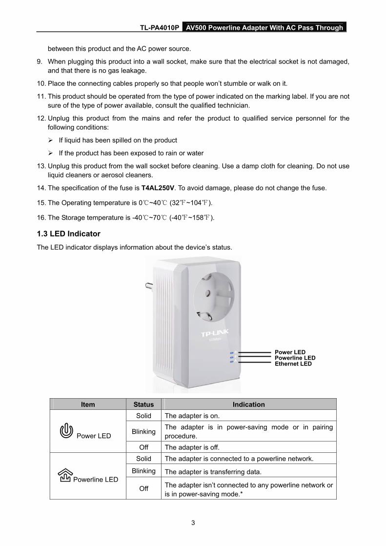
1.3 LED Indicator
The LED indicator displays information about the device’s status.
Item Status Indication
Solid The adapter is on.
Blinking The adapter is in power-saving mode or in pairing procedure. Power LED
Off The adapter is off.
Solid The adapter is connected to a powerline network.
Blinking The adapter is transferring data. Powerline LED
Off The adapter isn’t connected to any powerline network or is in power-saving mode.*
Power LED Powerline LED Ethernet LED
TL-PA4010P AV500 Powerline Adapter With AC Pass Through
4
Solid The Ethernet port is connected, but there is no data being transferred.
Blinking The Ethernet port is transferring data. Ethernet LED
Off The Ethernet port isn’t connected.
Note:
5 minutes after the device connected to the adapter is turned off, and the adapter will automatically switch to the power-saving Mode. In power-saving mode, the Homeplug cannot be accessed via the electrical wiring, but its integrated electrical socket can supply the power normally. As soon as the device connected to the Homeplug is switched on again, your Homeplug will leave the power-saving mode and the three LEDs will flash simultaneously.
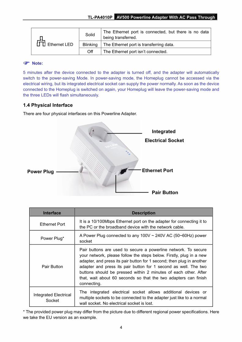
1.4 Physical Interface
There are four physical interfaces on this Powerline Adapter.
Power Plug Ethernet Port
Pair Button
Integrated
Electrical Socket
Interface Description
Ethernet Port It is a 10/100Mbps Ethernet port on the adapter for connecting it to the PC or the broadband device with the network cable.
Power Plug* A Power Plug connected to any 100V ~ 240V AC (50~60Hz) power socket
Pair Button
Pair buttons are used to secure a powerline network. To secure your network, please follow the steps below. Firstly, plug in a new adapter, and press its pair button for 1 second; then plug in another adapter and press its pair button for 1 second as well. The two buttons should be pressed within 2 minutes of each other. After that, wait about 60 seconds so that the two adapters can finish connecting.
Integrated Electrical Socket
The integrated electrical socket allows additional devices or multiple sockets to be connected to the adapter just like to a normal wall socket. No electrical socket is lost.
* The provided power plug may differ from the picture due to different regional power specifications. Here we take the EU version as an example.

TL-PA4010P AV500 Powerline Adapter With AC Pass Through
5
Note:
1. If you press the pair button for more than 10 seconds, the powerline adapter will leave the network which it has joined and its new network name assumes a random value. The Power LED turns off temporarily when it disconnects from the powerline network.
2. For detailed information about the pair button, please refer to Chapter 5 Advanced Feature: How to Use the Pair Buttons.
TL-PA4010P AV500 Powerline Adapter With AC Pass Through
6
Chapter 2 Connecting Mechanism
2.1 Introduction
The Powerline Adapter supports up to 500Mbps data rate. With this high speed connection rate, this Powerline Adapter allows you to set up a high speed home network by using your home existing electrical wiring. Simply plug this Powerline Adapter into an ordinary power outlet to extend your Cable/xDSL broadband connection or existing LAN network to any other electrical outlet in any room of your house.
Note that this Powerline Adapter works in pairs. You need to plug one Powerline Adapter into a power outlet for each computer and connect the Powerline Adapter to the computer’s LAN card with an Ethernet cable; you will also need another Powerline Adapter connected to your Cable/xDSL broadband so as to extend your broadband connection or Internet surfing. With clean power line, the distance between two Powerline Adapters can reach 300 meters at most, but the actual distance may vary due to the environment.
Section below describes the connection instructions and hardware connection mechanism.
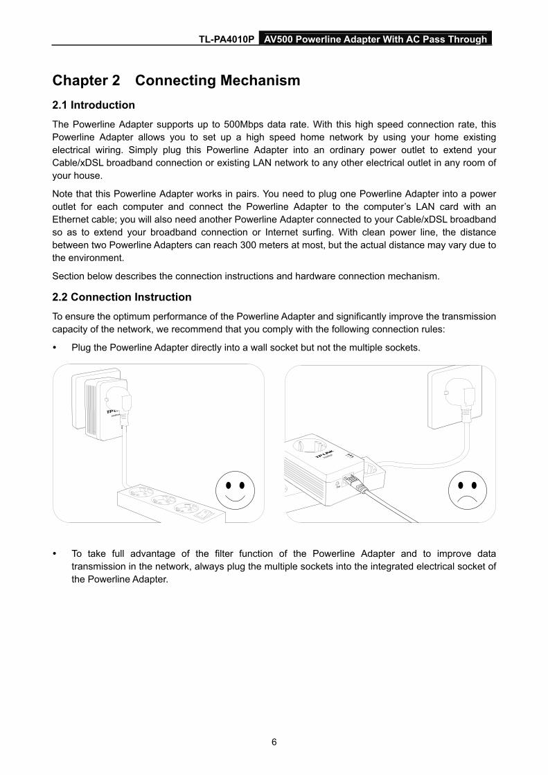
2.2 Connection Instruction
To ensure the optimum performance of the Powerline Adapter and significantly improve the transmission capacity of the network, we recommend that you comply with the following connection rules:
Plug the Powerline Adapter directly into a wall socket but not the multiple sockets.
To take full advantage of the filter function of the Powerline Adapter and to improve data
transmission in the network, always plug the multiple sockets into the integrated electrical socket of the Powerline Adapter.
TL-PA4010P AV500 Powerline Adapter With AC Pass Through
7
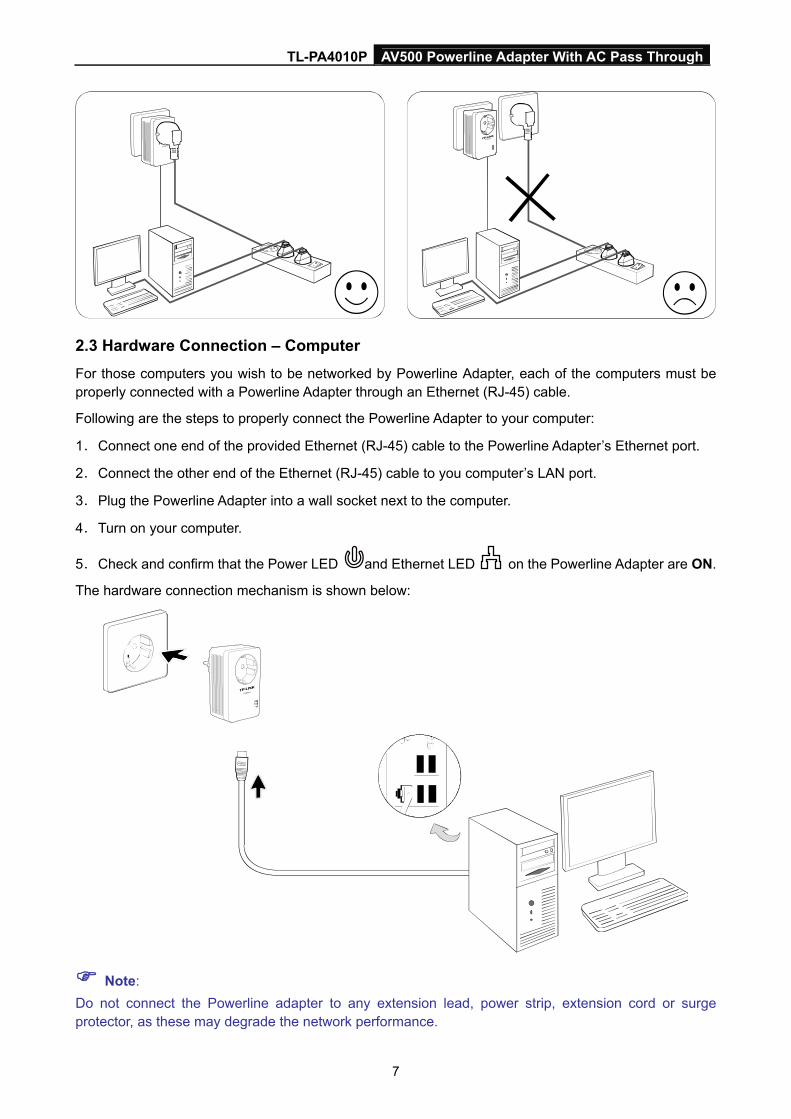
2.3 Hardware Connection – Computer
For those computers you wish to be networked by Powerline Adapter, each of the computers must be properly connected with a Powerline Adapter through an Ethernet (RJ-45) cable.
Following are the steps to properly connect the Powerline Adapter to your computer:
1. Connect one end of the provided Ethernet (RJ-45) cable to the Powerline Adapter’s Ethernet port.
2. Connect the other end of the Ethernet (RJ-45) cable to you computer’s LAN port.
3. Plug the Powerline Adapter into a wall socket next to the computer.
4. Turn on your computer.
5. Check and confirm that the Power LED and Ethernet LED on the Powerline Adapter are ON.
The hardware connection mechanism is shown below:
Note:
Do not connect the Powerline adapter to any extension lead, power strip, extension cord or surge protector, as these may degrade the network performance.
TL-PA4010P AV500 Powerline Adapter With AC Pass Through
8
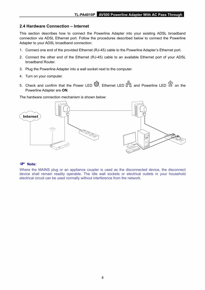
2.4 Hardware Connection – Internet
This section describes how to connect the Powerline Adapter into your existing ADSL broadband connection via ADSL Ethernet port. Follow the procedures described below to connect the Powerline Adapter to your ADSL broadband connection:
1. Connect one end of the provided Ethernet (RJ-45) cable to the Powerline Adapter’s Ethernet port.
2. Connect the other end of the Ethernet (RJ-45) cable to an available Ethernet port of your ADSL broadband Router.
3. Plug the Powerline Adapter into a wall socket next to the computer.
4. Turn on your computer.
5. Check and confirm that the Power LED , Ethernet LED , and Powerline LED on the Powerline Adapter are ON.
The hardware connection mechanism is shown below:
Note:
Where the MAINS plug or an appliance coupler is used as the disconnected device, the disconnect device shall remain readily operable. The idle wall sockets or electrical outlets in your household electrical circuit can be used normally without interference from the network.
TL-PA4010P AV500 Powerline Adapter With AC Pass Through
9
Chapter 3 Installing Management Utility Please verify that no other Powerline Adapter or any Encryption Management Utilities are installed before installing the provided software. If other Powerline Utilities are installed, uninstall them and restart your personal computer before installing this provided software.
Note:
To install Management Utility, please make sure that WinPcap 4.1.2 has been installed in your computer.
Otherwise, a window will pop up for you to install WinPcap 4.1.2.
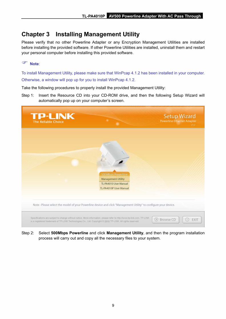
Take the following procedures to properly install the provided Management Utility:
Step 1: Insert the Resource CD into your CD-ROM drive, and then the following Setup Wizard will automatically pop up on your computer’s screen.
Step 2: Select 500Mbps Powerline and click Management Utility, and then the program installation
process will carry out and copy all the necessary files to your system.
TL-PA4010P AV500 Powerline Adapter With AC Pass Through
10
TL-PA4010P AV500 Powerline Adapter With AC Pass Through
11
TL-PA4010P AV500 Powerline Adapter With AC Pass Through
12
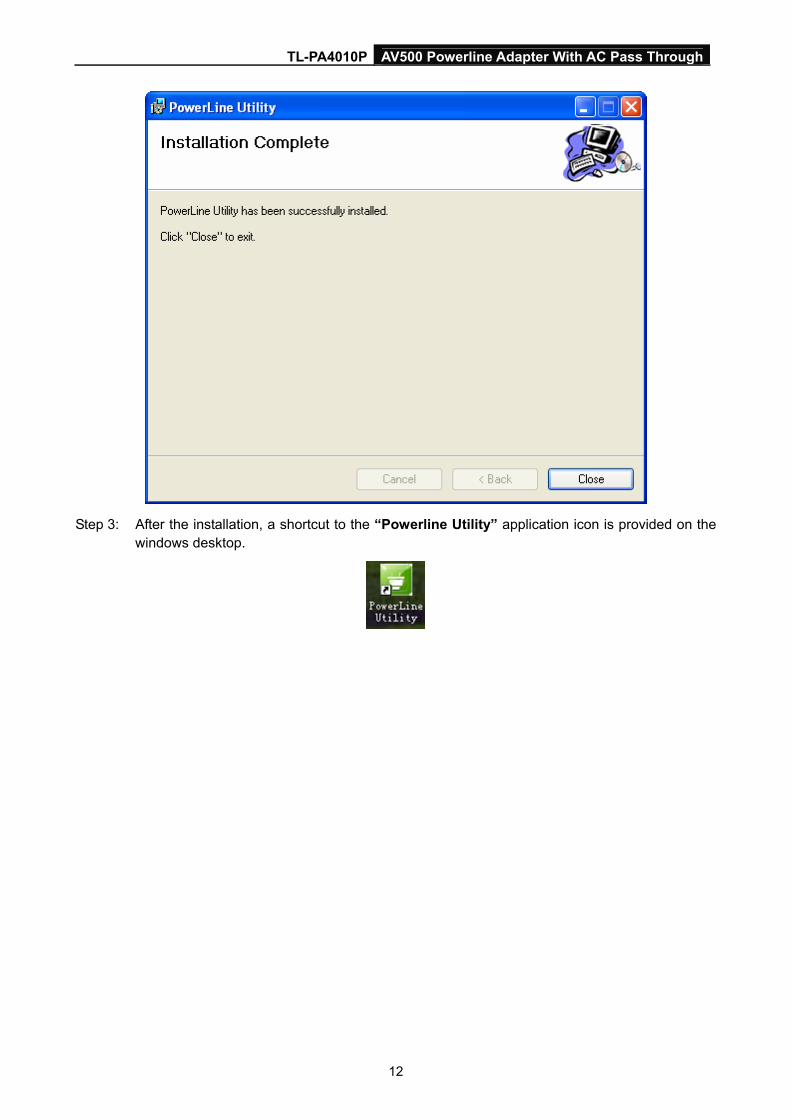
Step 3: After the installation, a shortcut to the “Powerline Utility” application icon is provided on the
windows desktop.
TL-PA4010P AV500 Powerline Adapter With AC Pass Through
13
Chapter 4 Using the Management Utility After you’d successfully installed the Powerline Adapter hardware and Management Utility software, you can set up or configure the devices according to your need.
This Powerline Utility enables the users to identify powerline devices on the powerline network, measures data rate performance and ensures privacy by setting user defined secure powerline networks.
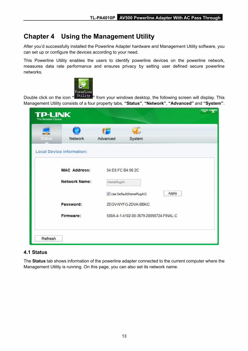
Double click on the icon “ ” from your windows desktop, the following screen will display. This Management Utility consists of a four property tabs, “Status”, “Network”, “Advanced” and “System”.
4.1 Status
The Status tab shows information of the powerline adapter connected to the current computer where the Management Utility is running. On this page, you can also set its network name.
TL-PA4010P AV500 Powerline Adapter With AC Pass Through
14
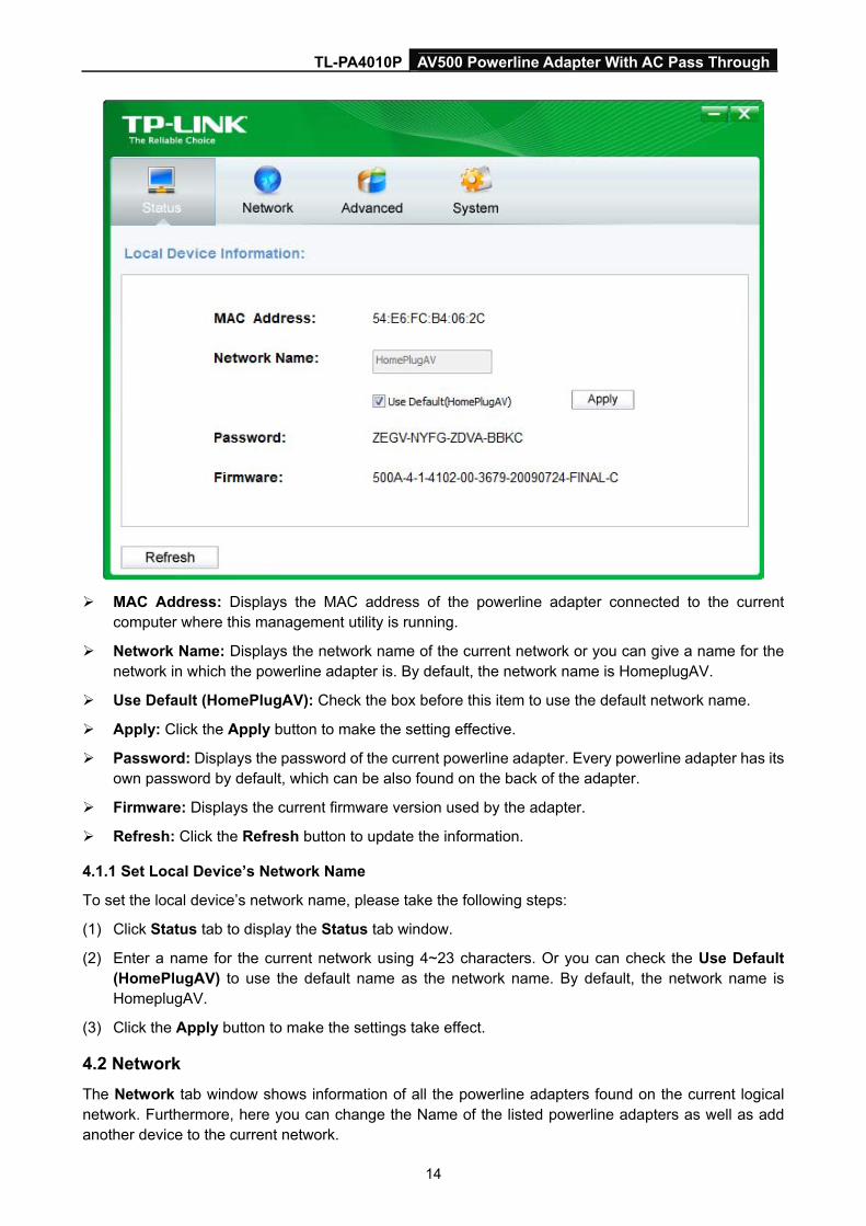
MAC Address: Displays the MAC address of the powerline adapter connected to the current
computer where this management utility is running.
Network Name: Displays the network name of the current network or you can give a name for the network in which the powerline adapter is. By default, the network name is HomeplugAV.
Use Default (HomePlugAV): Check the box before this item to use the default network name.
Apply: Click the Apply button to make the setting effective.
Password: Displays the password of the current powerline adapter. Every powerline adapter has its own password by default, which can be also found on the back of the adapter.
Firmware: Displays the current firmware version used by the adapter.
Refresh: Click the Refresh button to update the information.
4.1.1 Set Local Device’s Network Name
To set the local device’s network name, please take the following steps:
(1) Click Status tab to display the Status tab window.
(2) Enter a name for the current network using 4~23 characters. Or you can check the Use Default (HomePlugAV) to use the default name as the network name. By default, the network name is HomeplugAV.
(3) Click the Apply button to make the settings take effect.
4.2 Network
The Network tab window shows information of all the powerline adapters found on the current logical network. Furthermore, here you can change the Name of the listed powerline adapters as well as add another device to the current network.
TL-PA4010P AV500 Powerline Adapter With AC Pass Through
15
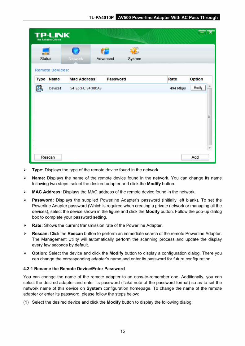
Type: Displays the type of the remote device found in the network.
Name: Displays the name of the remote device found in the network. You can change its name following two steps: select the desired adapter and click the Modify button.
MAC Address: Displays the MAC address of the remote device found in the network.
Password: Displays the supplied Powerline Adapter’s password (Initially left blank). To set the Powerline Adapter password (Which is required when creating a private network or managing all the devices), select the device shown in the figure and click the Modify button. Follow the pop-up dialog box to complete your password setting.
Rate: Shows the current transmission rate of the Powerline Adapter.
Rescan: Click the Rescan button to perform an immediate search of the remote Powerline Adapter. The Management Utility will automatically perform the scanning process and update the display every few seconds by default.
Option: Select the device and click the Modify button to display a configuration dialog. There you can change the corresponding adapter’s name and enter its password for future configuration.
4.2.1 Rename the Remote Device/Enter Password
You can change the name of the remote adapter to an easy-to-remember one. Additionally, you can select the desired adapter and enter its password (Take note of the password format) so as to set the network name of this device on System configuration homepage. To change the name of the remote adapter or enter its password, please follow the steps below:
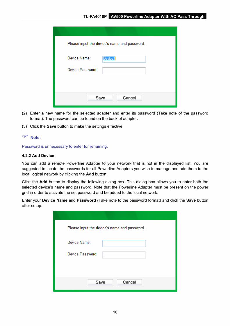
(1) Select the desired device and click the Modify button to display the following dialog.
TL-PA4010P AV500 Powerline Adapter With AC Pass Through
16
(2) Enter a new name for the selected adapter and enter its password (Take note of the password
format). The password can be found on the back of adapter.
(3) Click the Save button to make the settings effective.
Note:
Password is unnecessary to enter for renaming.
4.2.2 Add Device
You can add a remote Powerline Adapter to your network that is not in the displayed list. You are suggested to locate the passwords for all Powerline Adapters you wish to manage and add them to the local logical network by clicking the Add button.
Click the Add button to display the following dialog box. This dialog box allows you to enter both the selected device’s name and password. Note that the Powerline Adapter must be present on the power grid in order to activate the set password and be added to the local network.
Enter your Device Name and Password (Take note to the password format) and click the Save button after setup.
TL-PA4010P AV500 Powerline Adapter With AC Pass Through
17
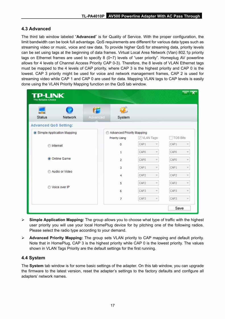
4.3 Advanced
The third tab window labeled “Advanced” is for Quality of Service. With the proper configuration, the limit bandwidth can be took full advantage. QoS requirements are different for various data types such as streaming video or music, voice and raw data. To provide higher QoS for streaming data, priority levels can be set using tags at the beginning of data frames. Virtual Local Area Network (Vlan) 802.1p priority tags on Ethernet frames are used to specify 8 (0~7) levels of “user priority”. Homeplug AV powerline allows for 4 levels of Channel Access Priority CAP 0-3). Therefore, the 8 levels of VLAN Ethernet tags must be mapped to the 4 levels of CAP priority, where CAP 3 is the highest priority and CAP 0 is the lowest. CAP 3 priority might be used for voice and network management frames, CAP 2 is used for streaming video while CAP 1 and CAP 0 are used for data. Mapping VLAN tags to CAP levels is easily done using the VLAN Priority Mapping function on the QoS tab window.
Simple Application Mapping: The group allows you to choose what type of traffic with the highest
user priority you will use your local HomePlug device for by pitching one of the following radios. Please select the radio type according to your demand.
Advanced Priority Mapping: The group sets VLAN priority to CAP mapping and default priority. Note that in HomePlug, CAP 3 is the highest priority while CAP 0 is the lowest priority. The values shown in VLAN Tags Priority are the default settings for the first running.
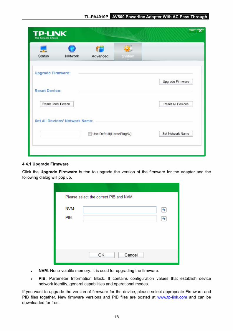
4.4 System
The System tab window is for some basic settings of the adapter. On this tab window, you can upgrade the firmware to the latest version, reset the adapter’s settings to the factory defaults and configure all adapters’ network names.
TL-PA4010P AV500 Powerline Adapter With AC Pass Through
18
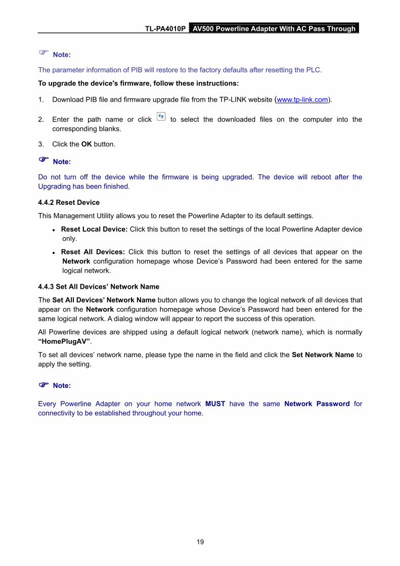
4.4.1 Upgrade Firmware
Click the Upgrade Firmware button to upgrade the version of the firmware for the adapter and the following dialog will pop up.
NVM: None-volatile memory. It is used for upgrading the firmware.
PIB: Parameter Information Block. It contains configuration values that establish device network identity, general capabilities and operational modes.
If you want to upgrade the version of firmware for the device, please select appropriate Firmware and PIB files together. New firmware versions and PIB files are posted at www.tp-link.com and can be downloaded for free.
TL-PA4010P AV500 Powerline Adapter With AC Pass Through
19
Note:
The parameter information of PIB will restore to the factory defaults after resetting the PLC.
To upgrade the device's firmware, follow these instructions:
1. Download PIB file and firmware upgrade file from the TP-LINK website (www.tp-link.com).
2. Enter the path name or click to select the downloaded files on the computer into the corresponding blanks.
3. Click the OK button.
Note:
Do not turn off the device while the firmware is being upgraded. The device will reboot after the Upgrading has been finished.
4.4.2 Reset Device
This Management Utility allows you to reset the Powerline Adapter to its default settings.
Reset Local Device: Click this button to reset the settings of the local Powerline Adapter device only.
Reset All Devices: Click this button to reset the settings of all devices that appear on the Network configuration homepage whose Device’s Password had been entered for the same logical network.
4.4.3 Set All Devices’ Network Name
The Set All Devices’ Network Name button allows you to change the logical network of all devices that appear on the Network configuration homepage whose Device’s Password had been entered for the same logical network. A dialog window will appear to report the success of this operation.
All Powerline devices are shipped using a default logical network (network name), which is normally “HomePlugAV”.
To set all devices’ network name, please type the name in the field and click the Set Network Name to apply the setting.
Note:
Every Powerline Adapter on your home network MUST have the same Network Password for connectivity to be established throughout your home.
TL-PA4010P AV500 Powerline Adapter With AC Pass Through
20
Chapter 5 Advanced Feature: How to Use the Pair Buttons
5.1 Pair (Secure with 128 bits-AES)
The Homeplug AV standard uses 128-bit AES (Advanced Encryption Standard) to safely transmit data between powerline adapters. For the powerline adapters to communicate with each other they all need to use the same Network Membership Key (NMK). Otherwise, they cannot unscramble the encrypted data sent in the powerline network.
The Pair button allows you to set up a secure powerline connection with another HomePlug AV compliant powerline devices which also support the Pair feature.
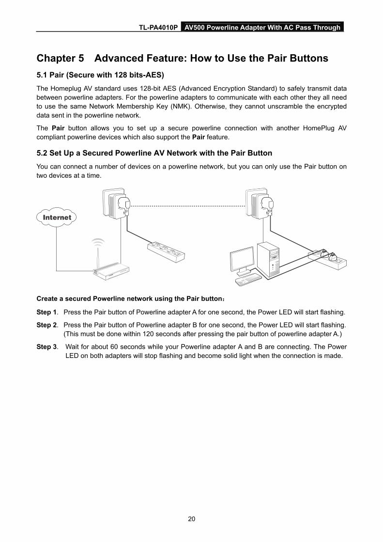
5.2 Set Up a Secured Powerline AV Network with the Pair Button
You can connect a number of devices on a powerline network, but you can only use the Pair button on two devices at a time.
Create a secured Powerline network using the Pair button:
Step 1. Press the Pair button of Powerline adapter A for one second, the Power LED will start flashing.
Step 2. Press the Pair button of Powerline adapter B for one second, the Power LED will start flashing. (This must be done within 120 seconds after pressing the pair button of powerline adapter A.)
Step 3. Wait for about 60 seconds while your Powerline adapter A and B are connecting. The Power LED on both adapters will stop flashing and become solid light when the connection is made.
TL-PA4010P AV500 Powerline Adapter With AC Pass Through
21
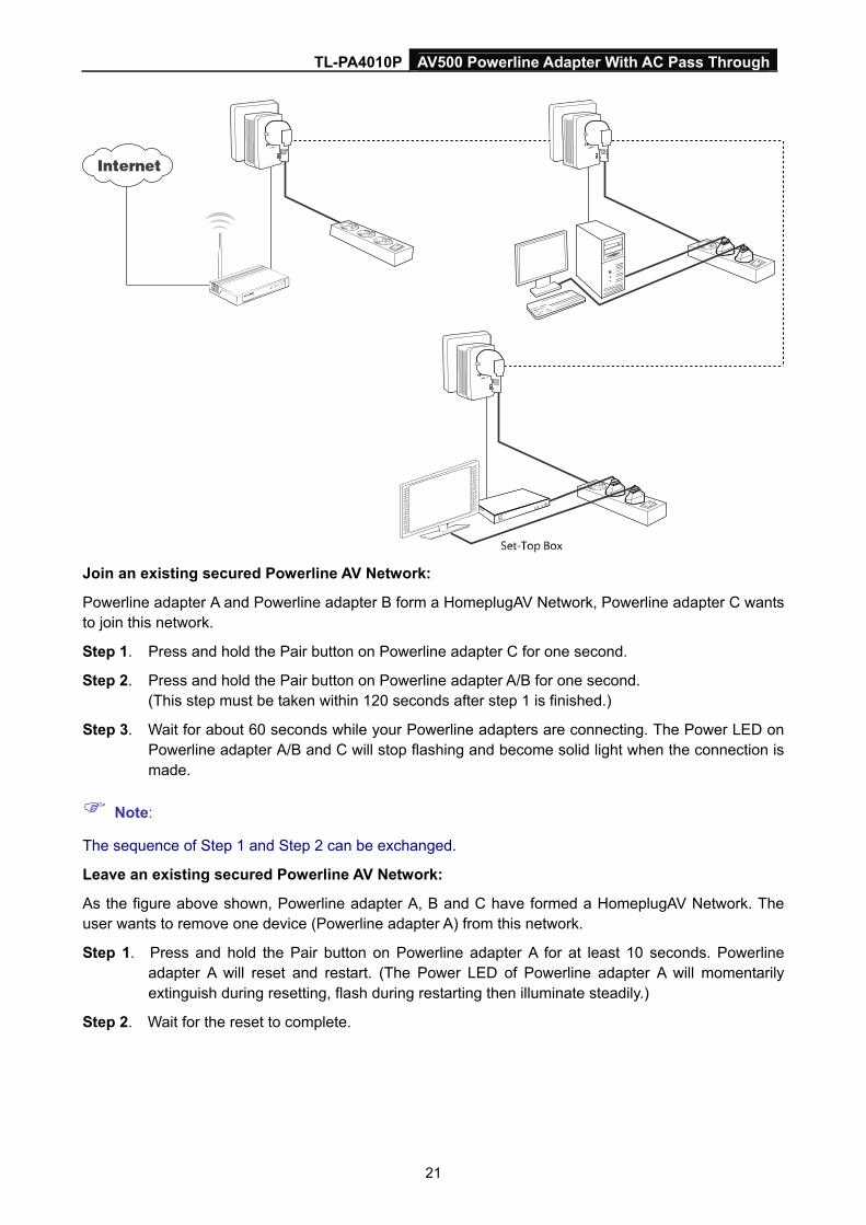
Join an existing secured Powerline AV Network:
Powerline adapter A and Powerline adapter B form a HomeplugAV Network, Powerline adapter C wants to join this network.
Step 1. Press and hold the Pair button on Powerline adapter C for one second.
Step 2. Press and hold the Pair button on Powerline adapter A/B for one second. (This step must be taken within 120 seconds after step 1 is finished.)
Step 3. Wait for about 60 seconds while your Powerline adapters are connecting. The Power LED on Powerline adapter A/B and C will stop flashing and become solid light when the connection is made.
Note:
The sequence of Step 1 and Step 2 can be exchanged.
Leave an existing secured Powerline AV Network:
As the figure above shown, Powerline adapter A, B and C have formed a HomeplugAV Network. The user wants to remove one device (Powerline adapter A) from this network.
Step 1. Press and hold the Pair button on Powerline adapter A for at least 10 seconds. Powerline adapter A will reset and restart. (The Power LED of Powerline adapter A will momentarily extinguish during resetting, flash during restarting then illuminate steadily.)
Step 2. Wait for the reset to complete.
TL-PA4010P AV500 Powerline Adapter With AC Pass Through
22
Appendix A: Troubleshooting The Troubleshooting provides answers to common problems regarding the Powerline Adapter.
1. The Power LED does not light up.
Ans. Check the following:
a) Make sure that the Powerline Adapter is properly plugged into a power outlet.
b) Make sure the power outlet is active (working) by plugging another electric device into it.
c) Re-plug the Powerline Adapter to the power outlet again. If the Power LED still fails to light up, contact your local dealer for technical support.
2. The Ethernet LED does not light up.
Ans. Check the following:
1. Make sure that the Ethernet cable (RJ-45) is properly connected to the Powerline Adapter’s Ethernet port.
2. Make sure that the other end of the Ethernet cable (RJ-45) is properly connected to the computer LAN card or to you Cable/xDSL Ethernet port.
3. Make sure your computer LAN card is properly installed and configured.
4. Make sure your Cable/xDSL broadband access is working and configured correctly.
5. Contact your local dealer for technical support if the Ethernet LED still fails to light up after the above procedures.
3. The Powerline LED does not light up.
Ans. Check the following:
1. Double click to enable the Management Utility and click the “Rescan” tab under the Network configuration homepage. The Management Utility will automatically detect all other Powerline Adapter on your power line network.
2. Try to plug a second Powerline Adapter into a nearby power outlet and check whether the Powerline LED lights up or not.
3. Contact your local dealer for technical support if the Powerline LED still fails to light up after the above procedures.