Sans titre - 2 · 2017. 12. 29. · Title: Sans titre - 2 Author: CREA1 Created Date: 20171225185449Z

TECHNICAL SPECIFICATION FOR COAXIAL SMA ATTENUATORS / TERMINATIONS REF. : RAD-GEN-ATCH-002 Date: October 31th, 2019 ISSUE: 1/D PAGE: 1 / 22
Reproduction interdite / Reproduction forbidden
Titre / Title
HIGH RELIABILITY
RF COAXIAL LOADS AND ATTENUATORS
GENERIC SPECIFICATION
Rédigé par / Written by Responsabilité / Responsibility Date Signature
S. POIZAT Space Project Manager 31/10/2019
Vérifié par / Verified by
V EUDELINE Space B. U. Manager 31/10/2019
Approuvée par / Approved by
C. DUMORTIER Space Quality Manager 31/10/2019

TECHNICAL SPECIFICATION FOR COAXIAL SMA ATTENUATORS / TERMINATIONS REF. : RAD-GEN-ATCH-002 Date: October 31th, 2019 ISSUE: 1/D PAGE: 2 / 22
Reproduction interdite / Reproduction forbidden
DOCUMENTATION CHANGE NOTICE
REVISION OR
ISSUE
DATE CHANGE
1/-
1/A
1/B
1/C
1/D
08/03/2013
02/06/2016
19/12/2016
16/10/2019
31/10/2019
Initial issue Update the description of the glitche test (Insertion loss stability in temperature), in according to ESCC 3408 specification Check for Lot failure Paragraph number & External Visual Inspection description (§13.2.4.) updated Added DPA test (optional): §13.2.21 Corrected cracking test value for SMA: 600g instead of 300g in §13.2.21
TECHNICAL SPECIFICATION FOR COAXIAL SMA ATTENUATORS / TERMINATIONS REF. : RAD-GEN-ATCH-002 Date: October 31th, 2019 ISSUE: 1/D PAGE: 3 / 22
Reproduction interdite / Reproduction forbidden
TABLE OF CONTENTS
1. SCOPE ............................................................................................................................................................ 5
1.1 SCOPE ................................................................................................................................................................. 5 1.2 TECHNICAL DESIGN ............................................................................................................................................ 5 1.3 PIECE PART PROCUREMENT: ............................................................................................................................... 5
1.3.1 Preliminary Piece Part Procurement: ........................................................................................................ 5 1.3.2 Sub-assembly part:...................................................................................................................................... 5 1.3.3 Final Components:...................................................................................................................................... 5
2. APPLICABLE DOCUMENTS ..................................................................................................................... 6
3. INSPECTION & RIGHTS ............................................................................................................................ 6
4. REQUIREMENTS ......................................................................................................................................... 6
4.1. SPECIFICATIONS ............................................................................................................................................ 6 4.1.1. Conditions and Methods of Test ........................................................................................................... 6 4.1.2. Manufacturer's Responsibility for Performance of Tests and Inspections ........................................... 6
4.2. DELIVERABLE COMPONENTS ........................................................................................................................ 7 4.3. LOT FAILURE ................................................................................................................................................ 7
4.3.1. Lot Failure ........................................................................................................................................... 7 4.3.2. Testing and Lot Acceptance Levels ...................................................................................................... 7
4.4. MARKING ...................................................................................................................................................... 7
5. PRODUCTION CONTROL ......................................................................................................................... 7
6. FINAL PRODUCTION TESTS .................................................................................................................... 7
6.1. GENERAL ...................................................................................................................................................... 7 6.2. TEST METHODS AND CONDITIONS ................................................................................................................ 7 6.3. DOCUMENTATION ......................................................................................................................................... 7
7. FAILURES ..................................................................................................................................................... 8
7.1. LOT FAILURE FOR FINAL PRODUCTION TESTS: .............................................................................................. 8 7.2. LOT FAILURE DURING 100 % TESTING FOR FINAL PRODUCTION TESTS......................................................... 8 7.3. LOT FAILURE DURING SAMPLE TESTING FOR QUALIFICATION AND LOT ACCEPTANCE TESTS: ...................... 8 7.4. FAILED COMPONENTS ................................................................................................................................... 8 7.5. FAILURE CRITERIA ........................................................................................................................................ 8
8. QUALIFICATION TESTS ........................................................................................................................... 9
8.1. QUALIFICATION TESTING .............................................................................................................................. 9 8.1.1. Sample Size .......................................................................................................................................... 9 8.1.2. Distribution within the Sample Lot for Qualification Testing .............................................................. 9 8.1.3. Qualification Testing ............................................................................................................................ 9
8.2. DOCUMENTATION ......................................................................................................................................... 9
9. LOT ACCEPTANCE TESTS ....................................................................................................................... 9
9.1. LOT ACCEPTANCE TESTING .......................................................................................................................... 9 9.1.1. Sample Size .......................................................................................................................................... 9 9.1.2. Distribution within the Sample Lot for Lot Acceptance Testing .......................................................... 9 9.1.3. Lot Acceptance Testing ........................................................................................................................ 9
9.2. DOCUMENTATION ......................................................................................................................................... 9
10. CHART OF FINAL PRODUCTION TESTS ........................................................................................ 10
Note 1: Applicable only if this option is ordered by the customer......................................................................... 10

TECHNICAL SPECIFICATION FOR COAXIAL SMA ATTENUATORS / TERMINATIONS REF. : RAD-GEN-ATCH-002 Date: October 31th, 2019 ISSUE: 1/D PAGE: 4 / 22
Reproduction interdite / Reproduction forbidden
11. CHART OF QUALIFICATION TESTING .......................................................................................... 11
12. CHART OF LOT ACCEPTANCE TEST .............................................................................................. 12
13.1. GENERAL: ............................................................................................................................................... 13 13.2. SUMMARISED TESTS CONDITIONS: .......................................................................................................... 13 13.2.1. THERMAL CYCLING ................................................................................................................................ 13 13.2.2 VIBRATION CYCLING .............................................................................................................................. 13
13.2.2.1. Mounting condition ........................................................................................................................ 13 13.2.2.2. Random vibration ........................................................................................................................... 14 13.2.2.3. Sine vibration ................................................................................................................................. 14
13.2.3 FEMALE CONTACT RETENTION ............................................................................................................... 14 13.2.4. EXTERNAL VISUAL INSPECTION .............................................................................................................. 14 13.2.5. ELECTRICAL MEASUREMENTS ................................................................................................................ 15
13.2.5.1. General .......................................................................................................................................... 15 13.2.5.2. Electrical Measurements at Room Temperature ............................................................................ 15 13.2.5.3. Electrical Measurements at High and Low Temperature .............................................................. 15
13.2.6 VIBRATION .............................................................................................................................................. 15 13.2.6.1. Mounting condition ........................................................................................................................ 15 13.2.6.2. Random vibration ........................................................................................................................... 15 13.2.6.3. Sine vibration ................................................................................................................................. 15
13.2.7. SHOCK .................................................................................................................................................... 16 13.2.7.1. Mounting condition ........................................................................................................................ 16 13.2.7.2. Shocks level .................................................................................................................................... 16
13.2.8. RAPID CHANGE IN TEMPERATURE ........................................................................................................... 16 13.2.9. CLIMATIC SEQUENCE .............................................................................................................................. 17
13.2.9.1. Dry Heat ......................................................................................................................................... 17 13.2.9.2. Damp Heat, Accelerated, First Cycle ............................................................................................ 17 13.2.9.3. Cold Test ........................................................................................................................................ 17 13.2.9.4. Low Air Pressure ............................................................................................................................ 17 13.2.9.5. Damp Heat, Accelerated, Remaining Cycles ................................................................................. 17
13.2.10. COUPLING PROOF TORQUE ................................................................................................................. 17 13.2.11. MATING AND UNMATING FORCES ....................................................................................................... 18 13.2.12. OPERATING LIFE .................................................................................................................................. 19 13.2.13. RF LEAKAGE (ONLY DURING QUALIFICATION TESTING)(IEC 61726) ................................................. 19 13.2.14. PEAK POWER ...................................................................................................................................... 19 13.2.15. DIMENSION CHECK AND WEIGHT ........................................................................................................ 19 13.2.16. PERMANENCE OF MARKING ................................................................................................................ 19 13.2.17 BURN-IN ........................................................................................................................................... 19 13.2.18. CONNECTOR REPEATABILITY .............................................................................................................. 19 13.2.19. GLITCHES (INSERTION LOSS STABILITY IN TEMPERATURE) .................................................................. 20 13.2.20. X-RAYS ............................................................................................................................................... 20 13.2.21. DESTRUCTIVE PART ANALYSIS (DPA – OPTIONAL TEST ON 3 SAMPLES)............................................. 20
14. DATA DOCUMENTATION ................................................................................................................... 21
14.1. GENERAL ................................................................................................................................................ 21 14.1.1. Final production test data .................................................................................................................. 22 14.1.2. Lot Acceptance Test data ................................................................................................................... 22 14.1.3. Qualification Testing data ................................................................................................................. 22 14.1.4. Failed Component List and Failure Analysis Report ......................................................................... 22
14.2. CERTIFICATE OF CONFORMITY ................................................................................................................ 22
15. DELIVERY ............................................................................................................................................... 22
16. PACKAGING AND DESPATCH ........................................................................................................... 22

TECHNICAL SPECIFICATION FOR COAXIAL SMA ATTENUATORS / TERMINATIONS REF. : RAD-GEN-ATCH-002 Date: October 31th, 2019 ISSUE: 1/D PAGE: 5 / 22
Reproduction interdite / Reproduction forbidden
1. SCOPE
1.1 Scope This specification covers the general requirements for procurement, including lot acceptance testing, and delivery of standard Fixed, RF Coaxial Attenuators and RF Coaxial Termination for Space application. These components type “ S ” are directly issued from standard technical design, proceeded and tested in accordance with ESA SCC philosophy. This specification contains the appropriate inspection and test schedules and also specifies the data documentation requirements. Components are delivered under RADIALL Quality Assurance Label.
1.2 Technical Design Materials:
Part Design Material Finishes SMA Coupling nut Stainless steel / Insulator PTFE/ULTEM / SMA socket CuBe 2 Ni 1µm / Au 2.5 µm SMA Plug CuBe 2 Ni 1µm / Au 2.5 µm Shell Stainless steel /
1.3 Piece Part Procurement: 1.3.1 Preliminary Piece Part Procurement:
Piece Part Inspection and Control Document Reference SMA coupling nuts and shells Visual
Conformity of treatment Dimensional (process)
Insulator Dimensional (process) Refer to P.Q.P. Shell Visual Chapter Part Design Document SMA Socket and Plug after protection
Conformity of plating Dimensional (process)
(PDD)
P.Q.P. : Product Quality Plan
1.3.2 Sub-assembly part: Sub-Assembly Part Inspection and Control Document Reference
Strip and contact soldering Visual 100% + Inspection only on functional areas according to ESA SCC 20500 Soldering :100%
Refer to P.Q.P.: Chapter Flow CHART Document (FCD)
Assembly of Strip and Contact Visual 100%
P.Q.P. : Product Quality Plan
1.3.3 Final Components: Final Part Inspection and Control Document Reference
Attenuators Cleaning and Final Inspection 100% After :see Final Production Test
Refer to PQP : Chapter Test Plan Document (TPD)
P.Q.P. : Product Quality Plan

TECHNICAL SPECIFICATION FOR COAXIAL SMA ATTENUATORS / TERMINATIONS REF. : RAD-GEN-ATCH-002 Date: October 31th, 2019 ISSUE: 1/D PAGE: 6 / 22
Reproduction interdite / Reproduction forbidden
2. APPLICABLE DOCUMENTS
All proceed shall be clearly identified in the applicable Product Quality Plan (P.Q.P.). Documentation Reference
Product Quality Plan (P.Q.P.) R413999000.PQP Production Flow CHART Refer to P.Q.P. -:Chapter Flow CHART
Document (FCD) Traceability The complete traceability is recorded but
not provided for each order. Refer to P.Q.P. Chapter Product Assurance Plan (PAQ)
Test Flow chart for Final Production Tests and Lot Acceptance Tests
Refer to P.Q.P.: Chapter Test Plan Document (TPD)
Certificate of conformity See P.Q.P. RADIALL Quality Manual MQR in force Resistance to solvents of markiing ESCC 248000
3. INSPECTION & RIGHTS The manufacturer shall be responsible of inspections performed during the complete manufacturing, the Final Production Tests and the Lot Acceptance Tests.
4. REQUIREMENTS The test requirements for procurement of qualified components shall only comprise Final Production Tests. Component procurement could be provided from different identified batches of previous manufacturing lot. If required on the order, Lot Acceptance Test or specific requirements could be added on the components with extra-charges. For qualification the components shall comprise Final Production Test and qualification program described paragraph 11.
4.1. Specifications Procurement and delivery of components shall be in conformity with this specification which shall apply in total unless otherwise specified herein or in the Detail specification .
4.1.1. Conditions and Methods of Test The conditions and methods of test shall be in accordance with the Product Quality Plan.
4.1.2. Manufacturer's Responsibility for Performance of Tests and Inspections The manufacturer shall be responsible for the performance of tests and inspections. These tests and inspections shall be performed at the plant. For qualification, tests could be performed by agreed external facility.
TECHNICAL SPECIFICATION FOR COAXIAL SMA ATTENUATORS / TERMINATIONS REF. : RAD-GEN-ATCH-002 Date: October 31th, 2019 ISSUE: 1/D PAGE: 7 / 22
Reproduction interdite / Reproduction forbidden
4.2. Deliverable Components Components delivered to this specification shall be processed in accordance with the relevant Product Quality Plan (P. Q. P.). Each delivered component shall be traceable to its production lot. Components delivered to this specification shall have completed satisfactorily all tests with the relevant testing levels.
4.3. Lot Failure 4.3.1. Lot Failure
Lot failure may occur during Final Production Test or Lot Acceptance Testing.
4.3.2. Testing and Lot Acceptance Levels This specification defines the testing severity and the Lot Acceptance testing. The Lot Acceptance levels are designated LAT1, LAT2 and comprise tests as follows: - level 2 (LAT2) -Endurance Subgroup - level 1 (LAT1) -Environmental and Mechanical Subgroup plus Endurance Subgroup.
4.4. Marking All components procured and delivered to this specification shall be marked in accordance with the Product Quality Plan (P.Q.P.) and shall contain the following details: - RADIALL part number - Date Code
5. PRODUCTION CONTROL The minimum requirements for production control, which are equally applicable to procurement, are defined in the Product Quality Plan.
6. FINAL PRODUCTION TESTS
6.1. General All components used for delivery and those submitted to Lot Acceptance tests, shall be subjected to tests and inspections in accordance with the Product Quality Plan.
6.2. Test Methods and Conditions Test methods and conditions are completely specified and performed in the order shown in the paragraph 10 referenced in “chart of Final Production Tests”.
6.3. Documentation Documentation of Final Production Test data shall be in accordance with the requirements of Para. 14 of this specification.

TECHNICAL SPECIFICATION FOR COAXIAL SMA ATTENUATORS / TERMINATIONS REF. : RAD-GEN-ATCH-002 Date: October 31th, 2019 ISSUE: 1/D PAGE: 8 / 22
Reproduction interdite / Reproduction forbidden
7. FAILURES A component shall be counted as a failure in any of the following cases: - mechanical failure, - handling failure, - lost component,
7.1. Lot Failure for Final Production Tests: In case of lot failure, the manufacturer shall alert the Orderer. A lot shall be considered as failed if the allowable number defined in the paragraph 7.2, has been exceeded.
7.2. Lot Failure during 100 % Testing for Final Production Tests If the number of components failed on the basis of the failure criteria described in Para 7.2. exceeds:
- 6 % of a lot larger than 50 components, - 3 devices of a lot between 20 and 50 components, - 2 devices of a lot smaller than 20 components,
then the lot shall be considered as failed. If a lot is composed of groups of components of one family defined in one Detail specification, but separately identifiable for any reason, then the lot failure criteria shall apply separately to each identifiable group.
7.3. Lot Failure during Sample Testing for Qualification and Lot Acceptance Tests: A lot shall be considered as failed if the number of allowable failures during sample testing in accordance with General Inspection Level II of IEC Publication No. 410 is exceeded. A component shall be counted as a limit failure if one or more parameters exceed the limit shown in the Detail specification. If lot failure occurs, a 100 % testing may be performed with the relevant lot failure criteria.
7.4. Failed Components The following criteria shall apply to: A component shall be considered as failed if one or more parameters exceed the limit shown in the Detail specification.
7.5. Failure Criteria The following criteria shall apply to qualification and Lot acceptance tests
- Environmental and Mechanical Test Failures: Components which fail during tests for which the pass/fail criteria are inherent in the test method, e.g; vibration, etc
- Electrical Failures: One or more applicable parameters exceed the requested limits shown in table 1 of the Detail specification when subjected to electrical measurements during environmental and endurance tests.

TECHNICAL SPECIFICATION FOR COAXIAL SMA ATTENUATORS / TERMINATIONS REF. : RAD-GEN-ATCH-002 Date: October 31th, 2019 ISSUE: 1/D PAGE: 9 / 22
Reproduction interdite / Reproduction forbidden
8. QUALIFICATION TESTS 8.1. Qualification Testing
8.1.1. Sample Size The sample sizes of the qualification and the applicable test requirements are specified in the paragraph Qualification chart.
8.1.2. Distribution within the Sample Lot for Qualification Testing The specification covers a range or series of components that are considered similar for each family of components. Attenuator samples shall be established by the manufacturer in accordance with the distribution of attenuation values.
8.1.3. Qualification Testing Test methods and conditions are completely specified and performed in the order shown in the paragraph 11 referenced “Chart of Qualification Testing”.
8.2. Documentation In the case of Qualification testing, the data shall be documented in accordance with the requirements of Para. 14
9. LOT ACCEPTANCE TESTS 9.1. Lot Acceptance Testing
9.1.1. Sample Size The sample sizes of the Lot Acceptance and the applicable test requirements are specified in the paragraph Lot Acceptance chart. Components selected for LAT tests shall be serialised prior the test.
9.1.2. Distribution within the Sample Lot for Lot Acceptance Testing The specification covers a range or series of components that are considered similar for each family of components. Attenuator samples shall be chosen in accordance with the attenuation values: minimum value, middle and the maximum value of the batch.
9.1.3. Lot Acceptance Testing Test methods and conditions are completely specified and performed in the order shown in the paragraph 12 referenced “Chart of Lot Acceptance Test”.
9.2. Documentation In the case of Lot Acceptance testing, the data shall be documented in accordance with the requirements of Para. 14

TECHNICAL SPECIFICATION FOR COAXIAL SMA ATTENUATORS / TERMINATIONS REF. : RAD-GEN-ATCH-002 Date: October 31th, 2019 ISSUE: 1/D PAGE: 10 / 22
Reproduction interdite / Reproduction forbidden
10. CHART OF FINAL PRODUCTION TESTS
FINAL PRODUCTION TEST CHART
Note 1: Applicable only if this option is ordered by the customer
Burn In para 13.2.17 (100%)
Thermal Cycling para 13.2.1 (100%)
Electrical Measurements para 13.2.5.2 (100%)
Vibration Cycling para 13.2.2 (100%)
Final Assembly and Marking
CHECK FOR LOT FAILURE Para 7.2
Electrical Measurements para 13.2.5.2 (100%) Dimension and Mass para 13.2.15 (3pcs)
Measurements at High & Low Temperature para 13.2.5.3 (3pcs)
Electrical Measurements para 13.2.5.2 (100%)
External Visual Inspection para 13.2.4 (100%)
Female Contact Retention para 13.2.3 (100%)
X-ray (Optional)1 para 13.2.20 (100%)

TECHNICAL SPECIFICATION FOR COAXIAL SMA ATTENUATORS / TERMINATIONS REF. : RAD-GEN-ATCH-002 Date: October 31th, 2019 ISSUE: 1/D PAGE: 11 / 22
Reproduction interdite / Reproduction forbidden
11. CHART OF QUALIFICATION TESTING
QUALIFICATION CHART (10 components after Final Production Test)
Environmental/Mechanical Subgroup
Endurance Subgroup
Electrical Subgroup
4 Components 3 Components 3 Components
Vibration Para 13.2.6
Rapid Change in Temperature
Para 13.2.8
Mechanical Shock
Para 13.2.7
Climatic Sequence
Para 13.2.9
Coupling Proof Torque
Para 13.2.10
Operating Life Para 13.2.12
R.F. Leakage Para 13.2.13
10 COMPONENTS
QUALIFICATION APPROVAL
Glitches Para 13.2.19
Connector Repeatability Para 13.2.18
0 Failure allowed 0 Failure allowed 0 Failure allowed
Total Failures allowed: 0
Mating Unmating Force
Para 13.2.11
Permanence of Marking
Para 13.2.16
Peak Power Para 13.2.14
X-ray Para 13.2.20
X-ray Para 13.2.20
X-ray Para 13.2.20
Glitches Para 13.2.19

TECHNICAL SPECIFICATION FOR COAXIAL SMA ATTENUATORS / TERMINATIONS REF. : RAD-GEN-ATCH-002 Date: October 31th, 2019 ISSUE: 1/D PAGE: 12 / 22
Reproduction interdite / Reproduction forbidden
12. CHART OF LOT ACCEPTANCE TEST
NOTES (1) The tests shown in this Chart are considered to be destructive
LEVEL2 3 COMPONENTS
Rapid Change in Temperature Para 13. 2.8
Vibration Para 13. 2.6 Endurance
Subgroup 3 Components
LEVEL 3
Climatic Sequence
Para 13.2.9
Mating and Unmating
Forces Para 13.2.11
Permanence of Marking
Para 13.2.16
LEVEL 1 7 components with associated connectors
Environmental Mechanical Subgroups
4 Components
LEVEL 3 LOT ACCEPTANCE
LEVEL 2 - LOT ACCEPTANCE (1)
LEVEL 1 – LOT ACCEPTANCE (1)
0 Failure allowed
0 Failure allowed
Connector Repeatability Para 13.2.18
Glitches Para 13.2.19
X-ray Para 13.2.20
X-ray Para 13.2.20
Operating Life Para 13.2.12
Glitches Para 13.2.19

TECHNICAL SPECIFICATION FOR COAXIAL SMA ATTENUATORS / TERMINATIONS REF. : RAD-GEN-ATCH-002 Date: October 31th, 2019 ISSUE: 1/D PAGE: 13 / 22
Reproduction interdite / Reproduction forbidden
13. TEST METHODS AND PROCEDURES
13.1. General: The complete test methods and procedures are specified in the Product Quality Plan (P.Q.P.) and in the Detail specification.
13.2. Summarised Tests Conditions: This paragraph details the summarised methods and procedures applied on components in accordance with the different chart (Final Production Test - Qualification Testing and Lot Acceptance Test).
13.2.1. Thermal Cycling The components shall be subjected to Test Nb of IEC Publication No. 60068-2-14. The number of cycles shall be 5 with 15 minutes at each extreme temperature given in the detail specification. The temperature change rate shall be 2 to 5°/mn. During thermal cycling, savers shall be connected to each connector.
13.2.2 Vibration Cycling
13.2.2.1. Mounting condition For Final production Test, the parts shall be held as follows:
XY
Accelerometer
Mechanical shock plate
Z

TECHNICAL SPECIFICATION FOR COAXIAL SMA ATTENUATORS / TERMINATIONS REF. : RAD-GEN-ATCH-002 Date: October 31th, 2019 ISSUE: 1/D PAGE: 14 / 22
Reproduction interdite / Reproduction forbidden
13.2.2.2. Random vibration For Final production Test, the parts shall be subjected to vibration cycling as specified below. The vibration cycle shall be applied in the three mutually perpendicular axes as defined in the detail specification.
Range (Hz) Level 20 – 100 +6dB / oct
100 – 1000 0.67g2/Hz 1000 - 2000 -3dB / oct
Global: 33grms Duration: 60s per axis
13.2.2.3. Sine vibration Not Applicable
13.2.3 Female Contact Retention These measurements shall be performed with a contact retention of 28.4 grams and should remain firmly attached to the connector. The requirements for these measurements apply to female contact only. Test pin configuration shall be as defined below.
Test pin configuration Steel test pin diameter : 0.902/0.904 mm. Engagement depth : 1.27/1.91 mm.
Engagement depth
Steel pin
90 ± 1.0°
R : 0.4 mm max
N6
13.2.4. External Visual Inspection External Visual Inspection shall be performed in accordance with ESCC Basic Specification No. 20500.
TECHNICAL SPECIFICATION FOR COAXIAL SMA ATTENUATORS / TERMINATIONS REF. : RAD-GEN-ATCH-002 Date: October 31th, 2019 ISSUE: 1/D PAGE: 15 / 22
Reproduction interdite / Reproduction forbidden
13.2.5. Electrical Measurements 13.2.5.1. General
Unless otherwise stated in the detail specification, the following measurements shall be made under the standard conditions tests referenced in the relevant CHART.
13.2.5.2. Electrical Measurements at Room Temperature The measurements of electrical characteristics shall be made in accordance with Table 1 of the Detail specification.
13.2.5.3. Electrical Measurements at High and Low Temperature The measurements of electrical characteristics shall be made at each extreme temperature. in accordance with Table 1 and 2 of the Detail specification
13.2.6 Vibration
13.2.6.1. Mounting condition For LAT or Qualification test, the parts shall be held as it’s described in the detail specification figure 2.
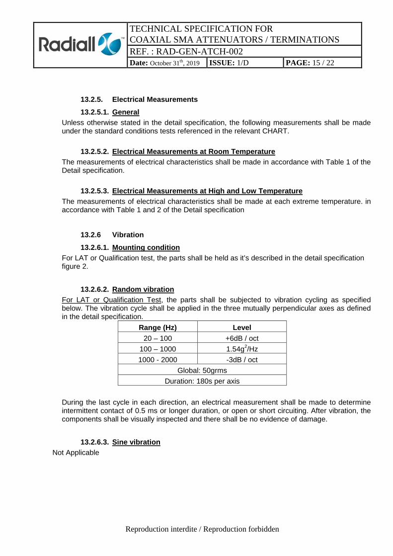
13.2.6.2. Random vibration For LAT or Qualification Test, the parts shall be subjected to vibration cycling as specified below. The vibration cycle shall be applied in the three mutually perpendicular axes as defined in the detail specification.
Range (Hz) Level 20 – 100 +6dB / oct
100 – 1000 1.54g2/Hz 1000 - 2000 -3dB / oct
Global: 50grms Duration: 180s per axis
During the last cycle in each direction, an electrical measurement shall be made to determine intermittent contact of 0.5 ms or longer duration, or open or short circuiting. After vibration, the components shall be visually inspected and there shall be no evidence of damage.
13.2.6.3. Sine vibration Not Applicable

TECHNICAL SPECIFICATION FOR COAXIAL SMA ATTENUATORS / TERMINATIONS REF. : RAD-GEN-ATCH-002 Date: October 31th, 2019 ISSUE: 1/D PAGE: 16 / 22
Reproduction interdite / Reproduction forbidden
13.2.7. Shock 13.2.7.1. Mounting condition
For Qualification test, the parts shall be held as it’s described in the detail specification figure 2.
13.2.7.2. Shocks level
All axis Frequency Shock Response spectrum (g) / Q=10
100 Hz 3 000 Hz 10 000 Hz
70 g 2 000 g 2 000 g
Number of events: 3 shocks per axis Min tolerances:
0dB within (100Hz – 10000Hz) After shock, the components shall be visually examined and there shall be no evidence of damage. Notes: 1- Shock Response Spectrum (SRS) specification is defined by a straight line on a log-log plot. SRS computations shall be made with the absolute acceleration time history using the maxi-max technique and a Q-factor Q=10. SRS computations shall be made at a minimum of 1/6 octave intervals. 2- The SRS shall be measured and plotted to 10kHz minimum. However, it is preferable to record the data out to 20kHz (40kHz if possible) for engineering information. 3- In case of a shock test based on a hammer or real pyrotechnic device, the input load in the direct and cross-talk directions shall be measured using diagonally opposite accelerometers against the device under test. The accelerometers being as close as possible to the interface feet of the device under test.
13.2.8. Rapid Change in Temperature The components shall be subjected to Test Na of IEC Publication No. 60068-2-14. For Qualification Test: The number of cycles shall be 100 with 15 minutes at each extreme storage temperature unless otherwise specified in the Detail specification (Table 2 - Maximum Ratings). For LAT Test: The number of cycles shall be 10 with 15 minutes at each extreme storage temperature unless otherwise specified in the Detail specification (Table 2 - Maximum Ratings). During Rapid change of temperature, savers shall be connected to each connector.

TECHNICAL SPECIFICATION FOR COAXIAL SMA ATTENUATORS / TERMINATIONS REF. : RAD-GEN-ATCH-002 Date: October 31th, 2019 ISSUE: 1/D PAGE: 17 / 22
Reproduction interdite / Reproduction forbidden
13.2.9. Climatic Sequence 13.2.9.1. Dry Heat
The components shall be subjected to test 'Ba' of IEC Publication No. 60068-2-2. Duration: 2 hours at maximum operating temperature as prescribed in the Detail specification (Table 2).
13.2.9.2. Damp Heat, Accelerated, First Cycle The components shall be subjected to Test 'D' of IEC Publication No. 60068-2-4 for one cycle at 24 hours.
13.2.9.3. Cold Test The components shall be subjected to Test 'Aa' of IEC Publication No. 60068-2-1. Duration: 2 hours at minimum operating temperature as prescribed in the Detail specification (Table 2).
13.2.9.4. Low Air Pressure The components shall be subjected to Test 'M' of IEC Publication No. 60068-2-13 under to following conditions:
- 1 to 2 minutes at 85 mbar, - temperature: + 15 to + 35°C.
13.2.9.5. Damp Heat, Accelerated, Remaining Cycles The components shall be subjected to Test 'D' of IEC Publication No. 60068-2-4 for 5 cycles of 24 hours.
13.2.10. Coupling Proof Torque To be tested to Special Inspection Level S-4, AQL 1.0 of IEC Publication No.410.
The connector shall be engaged with its mating counterpart (gauge) and the coupling nut tightened to the torque of 170 N.cm. After 1 minute, the connector pair shall be disconnected. The coupling mechanism shall not be dislodged and the interface dimensions of the connector (noted “h” & “j” for female and “p” & “r” for male contact) shall remain as specified on connector interface figures defined on § 13.2.11.

TECHNICAL SPECIFICATION FOR COAXIAL SMA ATTENUATORS / TERMINATIONS REF. : RAD-GEN-ATCH-002 Date: October 31th, 2019 ISSUE: 1/D PAGE: 18 / 22
Reproduction interdite / Reproduction forbidden
13.2.11. Mating and Unmating Forces To be tested to special Inspection Level S-4, AQL 1.0 of IEC Publication No.410.
The connector shall be mated with its mating gauge. During the entire mating or unmating cycle (until the connector is fully mated or unmated), the necessary torque shall not exceed 24 N.cm. A screw-coupling connector is fully mated with its mating gauge when their reference planes coincide. No additional thightening torque shall be applied. The gauge is a steel jig containing the critical interface dimensions defined below:
Female contact Male contact

TECHNICAL SPECIFICATION FOR COAXIAL SMA ATTENUATORS / TERMINATIONS REF. : RAD-GEN-ATCH-002 Date: October 31th, 2019 ISSUE: 1/D PAGE: 19 / 22
Reproduction interdite / Reproduction forbidden
13.2.12. Operating life The components shall be subjected to an operating life test of 1,000 hours at the ambient temperature. The parameters for operating life are given in the detail specification. They shall be tested at rated input power applied in cycles of 1.5 hour 'on' and 0.5 hour 'off' throughout the test. The half-hour 'off' periods is included in the total test duration. The test frequency shall be at adapted frequency(GHz). For Qualification test, 10 cycles at +70°C :1.5 Hours “on” and 0.5 hour “off” will be added after the 1,000 hours. After not less than 1,000 hours, the components shall be removed from the chamber and allowed to cool under standard atmospheric conditions for testing for not less than 1 hour and not more than 24 hours. The removal from the chamber shall take place at the end of the half-hour 'off' period.
13.2.13. RF Leakage (Only during Qualification Testing)(IEC 61726) The component shall be subjected to RF leakage measurement according to IEC Publication N°61726. (Reverberating chamber test method)
13.2.14. Peak Power The component shall be placed in still air and free Space at the standard atmospheric conditions. The specified peak power shall be applied 10 times to each end of the attenuators or to the load for the time specified in the detail specification; the other end of the attenuator shall be connected to a matched fixed coaxial load. After the component has cooled down to standard inspection conditions, the attenuation or resistance shall be measured.
13.2.15. Dimension Check and Weight This test shall be performed in accordance with the Detail specification requirement.
13.2.16. Permanence of Marking This test shall be performed in accordance with ESCC specifcation n°24800.
13.2.17 BURN-IN The conditions for Burn-in shall be as follow:
(a) : Input Power: P= 0 W (b) : Maximum Operating Temperature: T= 125 +0/-3°C (c) : Duration : t= 168 Hours.
13.2.18. Connector Repeatability This test shall be performed in accordance with the Detail specification requirement.

TECHNICAL SPECIFICATION FOR COAXIAL SMA ATTENUATORS / TERMINATIONS REF. : RAD-GEN-ATCH-002 Date: October 31th, 2019 ISSUE: 1/D PAGE: 20 / 22
Reproduction interdite / Reproduction forbidden
13.2.19. Glitches (Insertion Loss stability in temperature) Test vehicles shall be subjected to temperature cycling with the following conditions:
• Number of Temperature Cycles: 3 cycles with 15 minutes minimum at each operating temperature extreme as specified in Maximum Ratings in the Detail Specification.
• Temperature transfer slope: 3 ±1°C/minute • Power Applied During Cycling: 0dBm minimum. • Operating Frequency: the maximum operating frequency as specified in the Detail
Specification, unless otherwise specified. • Data Points: During testing, Insertion Loss shall be continuously monitored and recorded
once every 500ms as a minimum or alternatively an analogue recorder may be used. The following acceptance criteria shall apply:
• No single Insertion loss discontinuity, step or spike shall exceed 0.05dB over each second. NOTE: In order for any observed glitch to be considered as a single Insertion Loss discontinuity, step or spike, it shall be evident on more than one temperature cycle. Otherwise it may be ignored. This test shall be performed in accordance with the Detail specification requirement.
13.2.20. X-rays - Radiographs shall be taken of the solder joints between the foil and the connector and the pin and centre conductor. The main criteria is the quality of the shape of the solder between pin and stripline. The voids in the soldering are not rejected criteria.
13.2.21. Destructive Part Analysis (DPA – Optional test on 3 samples if ordered) This test is done according to MIL STD 1580B with the following criterias for Load/Attenuator: 1. Visual inspection with checking of mechanical interface on all samples 2. X-rays (see §13.2.20) on all samples 3. Microsectioning on 1 sample with checking:
• Soldering shape and quality (according to FIPA 026 915S, available for consulting at Radiall factory only)
• Positioning of all parts according to the engenering drawing 4. Dismantling on 1 sample with checking:
• Visual inspection of each part
• Visual inspection of soldering
• Cracking test of the soldering between center contact and stripline with a criteria of : 120g min for SMA2.9, 600g min for SMA
5. Plating thickness on 1 sample: on all parts with plating (Au, Silver, Ni,…) excepted passivated parts (stainless steel passivated).

TECHNICAL SPECIFICATION FOR COAXIAL SMA ATTENUATORS / TERMINATIONS REF. : RAD-GEN-ATCH-002 Date: October 31th, 2019 ISSUE: 1/D PAGE: 21 / 22
Reproduction interdite / Reproduction forbidden
14. DATA DOCUMENTATION 14.1. General This package shall be compiled from: - (a) Final production test data - (b) Lot Acceptance Test Data - (c) Failed component list and Failed Analysis report. - (d) Certificate of Conformity. - (e) Manufacturing and Control Flow CHART.
Document Reference Delivered with the product Available at the plant Flow CHART Document X Lot Failure X X Lot Acceptance Test Data X Qualification Testing Data X Final Production Test Data X X Control Finishing of materials X Lot Traceability X X Certificate of conformity X X

TECHNICAL SPECIFICATION FOR COAXIAL SMA ATTENUATORS / TERMINATIONS REF. : RAD-GEN-ATCH-002 Date: October 31th, 2019 ISSUE: 1/D PAGE: 22 / 22
Reproduction interdite / Reproduction forbidden
14.1.1. Final production test data
A test result summary shall be compiled showing the total number of components submitted to, and the total number rejected after, each of the following tests indicated on the production chart. The compiled final production test data shall form an integral part of the data documentation package. No RF curves are recorded, only Pass - Fail results are recorded.
14.1.2. Lot Acceptance Test data Test result summary shall be compiled showing the total number of components submitted to, and the total number rejected after, each of the following tests indicated on the Lot Acceptance chart.
14.1.3. Qualification Testing data Test result summary shall be compiled showing the total number of components submitted to, and the total number rejected after, each of the following tests indicated on the qualification chart. All complete results are available at the plant.
14.1.4. Failed Component List and Failure Analysis Report The failed component list failure analysis report shall provide full details of : - (a) the reference number and description of the test; - (b) the failed parameter and the failure mode of the component;
14.2. Certificate of Conformity A certificate of conformity shall be established as defined in the Product Quality Plan.
15. DELIVERY
For procurement, for each order, the items forming the delivery are: - (a) the Delivery Lot;
- (b) the LAT report if ordered with the parts used for it - (c) the relevant documentation in accordance with the requirements of Section 14 of
this specification.
16. PACKAGING AND DESPATCH
The packaging and despatch of components to this specification shall be in accordance with the requirement of the Product Quality Plan