
Title Spatial localization of resistive drift wave...
11
Title Spatial localization of resistive drift wave structure in tokamak edge plasmas with an embedded magnetic island Author(s) Hu, Shilin; Li, Jiquan; Qu, Hongpeng; Kishimoto, Y. Citation Physics of Plasmas (2014), 21(10) Issue Date 2014-10 URL http://hdl.handle.net/2433/191241 Right Copyright 2014 American Institute of Physics. This article may be downloaded for personal use only. Any other use requires prior permission of the author and the American Institute of Physics. Type Journal Article Textversion publisher Kyoto University
-
Upload
hoangkhanh -
Category
Documents
-
view
226 -
download
0
Transcript of Title Spatial localization of resistive drift wave...

Title Spatial localization of resistive drift wave structure in tokamakedge plasmas with an embedded magnetic island
Author(s) Hu, Shilin; Li, Jiquan; Qu, Hongpeng; Kishimoto, Y.
Citation Physics of Plasmas (2014), 21(10)
Issue Date 2014-10
URL http://hdl.handle.net/2433/191241
Right
Copyright 2014 American Institute of Physics. This article maybe downloaded for personal use only. Any other use requiresprior permission of the author and the American Institute ofPhysics.
Type Journal Article
Textversion publisher
Kyoto University

Spatial localization of resistive drift wave structure in tokamak edge plasmas with anembedded magnetic islandShilin Hu, Jiquan Li, Hongpeng Qu, and Y. Kishimoto Citation: Physics of Plasmas (1994-present) 21, 102508 (2014); doi: 10.1063/1.4897942 View online: http://dx.doi.org/10.1063/1.4897942 View Table of Contents: http://scitation.aip.org/content/aip/journal/pop/21/10?ver=pdfcov Published by the AIP Publishing Articles you may be interested in Development of drift-resistive-inertial ballooning transport model for tokamak edge plasmas Phys. Plasmas 17, 082511 (2010); 10.1063/1.3478979 A drift-magnetohydrodynamical fluid model of helical magnetic island equilibria in the pedestals of H-modetokamak plasmas Phys. Plasmas 17, 062503 (2010); 10.1063/1.3432720 Nonlinear three-mode interaction and drift-wave turbulence in a tokamak edge plasma Phys. Plasmas 13, 042510 (2006); 10.1063/1.2184291 Wall intersection of ion orbits induced by fast transport of pedestal plasma over an electrostatic potential hill in atokamak plasma edge Phys. Plasmas 12, 102501 (2005); 10.1063/1.2052487 Predicting core and edge transport barriers in tokamaks using the GLF23 drift-wave transport model Phys. Plasmas 12, 052503 (2005); 10.1063/1.1886826
This article is copyrighted as indicated in the article. Reuse of AIP content is subject to the terms at: http://scitation.aip.org/termsconditions. Downloaded to IP:
130.54.110.73 On: Tue, 25 Nov 2014 02:54:08

Spatial localization of resistive drift wave structure in tokamak edge plasmaswith an embedded magnetic island
Shilin Hu,1 Jiquan Li,2,a) Hongpeng Qu,1 and Y. Kishimoto2,3
1Southwestern Institute of Physics, Sichuan, Chengdu 610041, China2Graduate School of Energy Science, Kyoto University, Gokasho, Uji, Kyoto 6110011, Japan3Institute of Advanced Energy, Kyoto University, Gokasho, Uji, Kyoto 6110011, Japan
(Received 24 June 2014; accepted 30 September 2014; published online 16 October 2014)
Resistive drift wave instability is investigated numerically in tokamak edge plasma confined by
sheared slab magnetic field geometry with an embedded magnetic island. The focus is on the
structural characteristics of eigenmode inside the island, where the density profile tends to be
flattened. A transition of the dominant eigenmode occurs around a critical island width wc. For thin
islands with a width below wc, two global long wavelength eigenmodes with approximately the
same growth rate but different eigenfrequency are excited, which are stabilized by the magnetic
island through two-dimensional mode coupling in both x and y (corresponding to radial and poloi-
dal in tokamak) directions. On the other hand, a short wavelength eigenmode, which is destabilized
by thick islands with a width above wc, dominates the edge fluctuation, showing a prominent struc-
tural localization in the region between the X-point and the O-point of the magnetic island. The
main destabilization mechanism is identified as the mode coupling in the y direction, which is simi-
lar to the so-called toroidal coupling in tokamak plasmas. These three eigenmodes may coexist in
the drift wave fluctuation for the island with a width around wc. It is demonstrated that the struc-
tural localization results mainly from the quasilinear flattening of density profile inside the mag-
netic island. VC 2014 AIP Publishing LLC. [http://dx.doi.org/10.1063/1.4897942]
I. INTRODUCTION
Magnetic islands are frequently observed in magnetic
fusion plasmas. They can be created through MHD instabil-
ities such as various tearing modes including neoclassical tear-
ing mode (NTM), error fields, or externally imposed resonant
magnetic perturbations (RMPs).1–7 The overlap of large long-
wavelength islands may cause plasma disruption so that the
plasma confinement is deteriorated. Even the dynamics of me-
dium size islands can also give rise to periodic oscillation
behavior such as the sawtooth around the rational surface of
q¼ 1 in tokamak plasmas. On the other hand, it has been real-
ized that the magnetic island may probably benefit the reduc-
tion of plasma fluctuations. In this respect, besides the
theoretical exploration of the effect of magnetic island on
microturbulence, experimental efforts to mitigate or suppress
the edge localized modes (ELMs) by external RMPs have
been made first in DIII-D, then confirmed in other devices
such as JET and ASDEX-U.5–7 Even if early theoretical stud-
ies on plasma response to the static RMPs have predicted a
screening effect of external RMPs produced by plasma rota-
tion,8 recent simulations have shown the potentialities of
island penetration, at least for some probable parameter win-
dows,9–13 besides the experimental efforts.14 Hence, the mag-
netic island dynamics are of importance in plasma equilibrium
and transport control as well as the confinement improvement.
In tokamak plasmas, the occurrence of magnetic islands
often alters pressure profile, which provides a driving force
of short wavelength instabilities, e.g., the drift wave and
resistive interchange mode. The island formation and evolu-
tion thus occur in a turbulent environment. In fact, different
scale fluctuations can be excited by individual driving force
and coexist together. They interact nonlinearly and affect
each other, probably producing new turbulent structures and
transport phenomena. Generally, macroscopic MHD activ-
ities with magnetic island dynamics may inevitably lead to
global energy confinement degradation.15 The magnetic
island can cause the plasma profile flattened inside island
separatrix due to large parallel transport along the field lines
so that the core temperature decreases. The energy confine-
ment thus tends to deteriorate. On the other hand, the global
magnetic island structure can give rise to a two-dimensional
(2D) mode coupling in both radial and poloidal directions to
form a global structure of micro-scale fluctuations.16 Such
mode coupling transfers fluctuation energy from unstable
components to stable or highly damped region, leading to a
dissipation of microturbulence. Recently, extensive investi-
gations on the effect of magnetic island on the microinstabil-
ities, e.g., the ion temperature gradient (ITG) mode have
been carried out based on fluid (gyrofluid) and gyrokinetic
simulations.16–27 Theoretical analysis in a gyrokinetic frame-
work is extended for small magnetic islands.28 Among com-
plicated linear and nonlinear interaction processes, the
mutual relation between the profile relaxation inside island
separatrix and the secondary excitation (or destabilization) is
an interesting issue. In the multiscale MHD and ITG turbu-
lence, linear analyses of the ITG instability with an initial
ion temperature profile with a static magnetic island have
showed a separation of rational surface from one into three
when the island width becomes larger than a critical thresh-
old, wc, leading to a destabilized global ITG mode. Such a
a)Author to whom correspondence should be addressed. Electronic mail:
1070-664X/2014/21(10)/102508/9/$30.00 VC 2014 AIP Publishing LLC21, 102508-1
PHYSICS OF PLASMAS 21, 102508 (2014)
This article is copyrighted as indicated in the article. Reuse of AIP content is subject to the terms at: http://scitation.aip.org/termsconditions. Downloaded to IP:
130.54.110.73 On: Tue, 25 Nov 2014 02:54:08

new ITG mode was referred to as the magnetic island
induced ITG mode, namely, the MITG mode.16 Though the
initial quasilinear flattening of pressure profile was ignored apriori, the predicted MITG has been qualitatively demon-
strated in a nonlinear gyrofluid simulation with consistent
evolution of dynamic magnetic island where the plasma pro-
file relaxation consistently takes place.27
The quasilinear flattening of density profile is also often
observed in resistive drift wave turbulence. What role the
profile flattening plays in destabilizing the drift wave is a key
question. Note that Wilson and Connor have analyzed the
effect of equilibrium profile modification by magnetic island
based on a rigorous gyrokinetic formalism (hereafter, it is
referred to as W&C theory).28 A reduction in density and
temperature gradients inside the island and a strong ~E � ~Bflow shear around it were observed. Most importantly, it pre-
dicted that the drift waves become more localized in the ydirection and the position of localized structure is not where
the drive for the instability is the strongest. A simplified
model, which involves a sinusoidal variation with y in the
pressure profile but removes the complication of magnetic
island geometry, was proposed to elucidate the underlying
mechanism. The same features of the mode structure could
be qualitatively reproduced as full model analysis. However,
this theory is valid for long, thin islands, with a width com-
parable to the ion Larmor radius. For thick islands, gyroki-
netic analysis is intractable since the magnetic island cannot
be treated as a perturbation. Hence, it calls for numerical
simulations to examine the analytical formalism and general-
ize the theoretical framework to large islands.
In this work, we conduct a numerical study on the dissi-
pative drift wave in tokamak edge plasma with an embedded
magnetic island to elaborate structural features of the eigen-
mode as well as instability characteristics. Simulations are
performed based on a Hasegawa–Wakatani (HW) model in a
slab configuration to limit the effect of profile relaxation on
the density only. It is observed that three global eigenmodes
may be excited. Thin islands stabilize two long wavelength
eigenmodes, but thick islands destabilize a short wavelength
one, showing a transition of the dominant eigenmode. The
destabilization is identified to mainly result from the mode
coupling in the y direction induced by the island. Most
importantly, simulations show a spatial localization of the
eigenmode structures in the region between the X-point and
the O-point of the island, mainly for thick islands. While we
have numerically examined the W&C theory, a model with
preset quasilinearly flattened density profile inside the mag-
netic island is proposed to clarify the underlying mechanism
of structural localization due to the island effects. Results
from modeling analyses are qualitatively in agreement with
the simulations as well as the W&C theory.
The remainder of this paper is organized as follows: In
Sec. II, the physical model and simulation settings are
described. Simulations of the drift wave instability versus the
magnetic island width are presented with an emphasis on the
features of eigenmode structure in Sec. III. Two modeling anal-
yses are implemented to identify the physical mechanism in
Sec. IV. Finally, achieved results are summarized and a brief
discussion on the zonal flow dynamics is given in Sec. V.
II. PHYSICAL MODEL AND SIMULATION SETTING
Our investigation is implemented in a 2D slab con-
figuration. The equilibrium magnetic field is composed of
a guide field Bt along the z direction with unit vector ez
and components in the perpendicular directions (x and y,
which correspond to the radial and “poloidal” directions
in tokamak, respectively) due to the existence of mag-
netic island. The resulting magnetic field ~B can be repre-
sented as16
~B ¼ Btez þ ez �rw; (1)
where w ¼ sx2=2þ ~wðxÞ cosðkTyÞ. Here, s denotes mag-
netic shear, ~wðxÞ the typical profile of the magnetic flux
perturbation calculated from the resistive tearing mode, and
kT the dominant wave number of the island, which usually
corresponds to the component of m ¼ 1 in the tearing
mode. The full island width can thus be estimated through
w � 4
ffiffiffiffiffiffiffiffiffiffiffiffiffiffiffi~wð0Þ=s
qin the “constant-~w” regime. The assump-
tion of static magnetic island is probably valid since it
evolves in a much slower time scale than microturbulence,
such as in the Rutherford regime of the tearing mode.
Effects of the magnetic island can be incorporated into the
drift wave model equations via the parallel operator r==
with a general expression
r==f ¼ ez �rw � r?f ¼ �r==f þ ½~w cosðkTyÞ; f �; (2)
where �r== ¼ sx@y corresponds to the parallel operator in the
conventional slab model without magnetic island. The perpen-
dicular differential operator is expressed as r? ¼ ex@x þey@y and the Poisson bracket as ½g; f � ¼ @xg@yf � @yg@xf .
Here f and g are any equilibrium and/or perturbation quanti-
ties, respectively. To highlight the response of density profile
to the existence of magnetic island, we use HW turbulence
model to describe the evolution of the resistive drift wave in
tokamak edge plasma, which consists of the continuity equa-
tion for density, n, and the equation for vorticity, r2?/ (here
/ is the electrostatic potential). The normalized equations are
written as follows:29,30
dt½nþ ðLn0=LnÞlnn0� ¼ D==r2==ðn� /Þ þ �?r2
?n; (3)
dtr2?/ ¼ D==r2
==ðn� /Þ þ l?r4?/; (4)
where dt ¼ @t þ ez �r/ � r, the normalized coefficient D==
is inversely proportional to the resistivity g as
D== ¼ Teðgn0e2xciLn0qsÞ�1, namely, inverse normalized re-
sistivity. The parameters �? and l? are particle diffusion
coefficient and ion viscosity, respectively. Here, n0 and n are
equilibrium and perturbed electron density, respectively. The
time and perpendicular coordinates are normalized as
xcitðqs=Ln0Þ ! t; ðx=qs; y=qsÞ ! ðx; yÞ: (5)
Then, the potential and density perturbation are normalized as
ðLn0=qsÞðe~/=TeÞ ! /; ðLn0=qsÞð~n=n0Þ ! n: (6)
102508-2 Hu et al. Phys. Plasmas 21, 102508 (2014)
This article is copyrighted as indicated in the article. Reuse of AIP content is subject to the terms at: http://scitation.aip.org/termsconditions. Downloaded to IP:
130.54.110.73 On: Tue, 25 Nov 2014 02:54:08

Here L�1n0 ¼ j@xlnn0jx¼0, qs ¼
ffiffiffiffiffiffiffiffiffiffiffiffiTe=mi
p=xci, and xci is the ion gyroradius. In this work, we focus on the structural features of
linear drift wave with an embedded magnetic island. Hence, the linearized HW equations involving the effects of magnetic
island are written as
@tnþ ðLn0=LnÞ@y/ ¼ D==�r2
==ðn� /Þ þ D==Kð~w; kTÞðn� /Þ þ �?r2?n; (7)
@tr2?/ ¼ D==
�r2
==ðn� /Þ þ D==Kð~w; kTÞðn� /Þ þ l?r4?/: (8)
The operator Kð~w; kTÞ is expressed explicitly with unfolded Poisson bracket in Eq. (2) as follows:
K ~w; kT
� �¼ sx cos kTyð Þ 2@x
~w@2yy þ k2
T~w@x
� �þ skT sin kTyð Þ ~w � x@x
~w� �
@y þ 2x~w@2xy
h iþ k2
T~w@x
~w@x
þ 1
2k2
T~w
2@2
xx þ @x~w
� �2@2
yy
h i� 1
2cos 2kTyð Þ k2
T~w
2@2
xx � @x~w
� �2@2
yy
h i
þ kT sin 2kTyð Þ 1
2~w@2
xx~w � @x
~w� �2
h i@y þ ~w@x
~w@2xy
� �: (9)
Obviously, the magnetic island can not only produce mode
coupling in the x direction through the variation of ~wðxÞ but
also couple the components in the y direction through the
sine and cosine factors. Furthermore, Eq. (9) also indicates
that the magnetic island can induce mode coupling with high
order harmonics, which may enhance the effect of large
islands on the drift wave instability.
Equations (7) and (8) form a coupling chain of all com-
ponents in the y direction so that the evolution of the fluctua-
tions can be solved easily as an initial value problem, where
Fourier spectral decomposition in the y direction and an
implicit finite difference scheme for x variable are
employed.19 That is, any perturbed quantity f is expressed as
f ðx; y; tÞ �X
m
fmðx; tÞ expði2pmy=LyÞ; (10)
with wave number ky ¼ 2pm=Ly. The boundary conditions
for all perturbed physical quantities are naturally periodic in
the y direction with periodic length Ly. The fixed boundary
condition (usually zero) is employed in the x direction with
the simulation box ½�Lx=2;þLx=2�.
III. SIMULATION FOR EIGENMODE ANALYSIS
To emphasize the effect of embedded magnetic island,
the drift wave instabilities are first simulated in reference pa-
rameter regions for direct comparison. Typical numerical pa-
rameters in simulations are chosen as: Lx ¼ 40 with grid
number of 512, Ly ¼ 20p with mode number of 10–30. The
time step is about dt ¼ 10�3. Simulations are started initially
with small random perturbation. The initial density profile is
set with varied gradient length Ln ¼ Ln0coshð2x=kÞ, where fi-
nite k can additionally limit radial mode width of the drift
wave except for the effect of finite magnetic shear. In this
work, usually k ¼ 6 is taken. The reference physical parame-
ters in simulations are chosen as l? ¼ �? ¼ 0:06,
D== ¼ 0:05, s ¼ 0:4 except for the particular description. Fig.
1 illustrates the parametric dependence of growth rates for
different inverse normalized resistivity D== and magnetic
shear s. The spectral peak of the linear growth rates is located
in the region of ky ¼ 0:6–1:1 and shifts to higher mode num-
ber for weak shear or large resistivity. The growth rates
decrease as the magnetic shear increases or the normalized
resistivity decreases (namely, D== / g�1 increases), showing
that the magnetic shear plays a stabilizing role and the resis-
tivity destabilizes the resistive drift wave. These results reveal
similar parametric dependences of the instability obtained in
a shearless slab.30 Furthermore, note that an elaborate analyti-
cal derivation of the resistive drift wave instability in sheared
FIG. 1. The growth rate of resistive drift wave versus ky for different dissi-
pation D== (a) or magnetic shear s (b). The reference parameters are used
except for l? ¼ �? ¼ 0:001, s ¼ 1:0 (a), D== ¼ 1:0 (b).
102508-3 Hu et al. Phys. Plasmas 21, 102508 (2014)
This article is copyrighted as indicated in the article. Reuse of AIP content is subject to the terms at: http://scitation.aip.org/termsconditions. Downloaded to IP:
130.54.110.73 On: Tue, 25 Nov 2014 02:54:08
slab configuration has been carried out recently, based on a
reduced electrostatic two-fluid model.31 The dependences of
the instability on both the magnetic shear and the resistivity
are also qualitatively in agreement with the observations in
our simulations. Fig. 2 plots contours of both potential and
density perturbations, exhibiting typical mode structures of
the resistive drift wave in a sheared slab.
When a magnetic island is embedded in the plasma, it
may give rise to some new effects. Typically, the pressure
profile (including density and/or temperature) tends to be
flattened inside the island separatrix. Furthermore, a new,
destabilized global MITG mode is induced, as described in
the Introduction. Moreover, zonal flows can be generated
through the linear mode coupling in the y direction due to
the existence of magnetic island. Such a mechanism is simi-
lar to the toroidal coupling for the excitation of the geodesic
acoustic mode (GAM) in a torus like tokamak.32,33 To fur-
ther understand the role of magnetic island in drift wave fluc-
tuations with quasilinear modification of equilibrium
profiles, in this work, a static island, which is likely created
by a tearing mode, is applied to the equilibrium configuration
as a perturbation with the singular layer coinciding with the
rational surface.
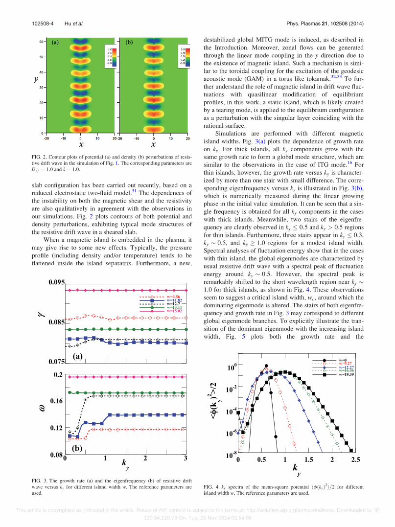
Simulations are performed with different magnetic
island widths. Fig. 3(a) plots the dependence of growth rate
on ky. For thick islands, all ky components grow with the
same growth rate to form a global mode structure, which are
similar to the observations in the case of ITG mode.16 For
thin islands, however, the growth rate versus ky is character-
ized by more than one stair with small difference. The corre-
sponding eigenfrequency versus ky is illustrated in Fig. 3(b),
which is numerically measured during the linear growing
phase in the initial value simulation. It can be seen that a sin-
gle frequency is obtained for all ky components in the cases
with thick islands. Meanwhile, two stairs of the eigenfre-
quency are clearly observed in ky � 0:5 and ky > 0:5 regions
for thin islands. Furthermore, three stairs appear in ky � 0:3,
ky � 0:5, and ky � 1:0 regions for a modest island width.
Spectral analyses of fluctuation energy show that in the cases
with thin island, the global eigenmodes are characterized by
usual resistive drift wave with a spectral peak of fluctuation
energy around ky � 0:5. However, the spectral peak is
remarkably shifted to the short wavelength region near ky �1:0 for thick islands, as shown in Fig. 4. These observations
seem to suggest a critical island width, wc, around which the
dominating eigenmode is altered. The stairs of both eigenfre-
quency and growth rate in Fig. 3 may correspond to different
global eigenmode branches. To explicitly illustrate the tran-
sition of the dominant eigenmode with the increasing island
width, Fig. 5 plots both the growth rate and the
FIG. 2. Contour plots of potential (a) and density (b) perturbations of resis-
tive drift wave in the simulation of Fig. 1. The corresponding parameters are
D== ¼ 1:0 and s ¼ 1:0.
FIG. 3. The growth rate (a) and the eigenfrequency (b) of resistive drift
wave versus ky for different island width w. The reference parameters are
used.
FIG. 4. ky spectra of the mean-square potential h/ðkyÞ2i=2 for different
island width w. The reference parameters are used.
102508-4 Hu et al. Phys. Plasmas 21, 102508 (2014)
This article is copyrighted as indicated in the article. Reuse of AIP content is subject to the terms at: http://scitation.aip.org/termsconditions. Downloaded to IP:
130.54.110.73 On: Tue, 25 Nov 2014 02:54:08

eigenfrequency versus the island width. For thin islands, two
global eigenmodes with nearly the same growth rate and dif-
ferent eigenfrequency dominate at long wavelengths with
ky � 0:5, labeled as EM1 and EM2, respectively. The thin
island has a stabilizing effect on them. To identify the stabili-
zation mechanism, simulations with and without zonal den-
sity, which mainly causes the radial flattening of density
profile, are performed. Comparison of the growth rates as
well as energy spectral analyses shows that the stabilization
mainly results from the island-induced 2D mode coupling in
the x and y directions since the fluctuation energy of unstable
components is noticeably transferred to highly damped
region. The zonal density created by linear mode coupling
due to the existence of magnetic island has less contribution
to the stabilization. However, thick islands destabilize
another eigenmode branch (EM3), which dominates the short
wavelength fluctuation with ky � 1:0. This may correspond
to the magnetic island induced ITG (namely, MITG) mode
observed in linear and nonlinear ITG simulations.16,27 The
destabilization might originate from two possible mecha-
nisms. One is related to the separation of the rational surface
due to thick islands, which is subject to the condition as
follows:
k== ! sx@y þ ½~w cosðkTyÞ; �� ¼ 0: (11)
As analyzed previously in the case of ITG mode,16 thick
islands can give rise to a separation of rational surface from
one (x ¼ 0) into three (x ¼ 0 and the other two neighbors
with finite distance) so that a radially global mode with
larger growth rate may be excited.34 The other mechanism
results from the mode coupling in the y direction induced by
the magnetic island (hereinafter referred to as ky mode cou-
pling). This kind of mode coupling is quite similar to the so-
called toroidal coupling in a torus. It may drive a new, more
unstable resistive drift wave, where adjacent ky components
couple with each other. However, in this case all ky compo-
nents are excited along the same rational surface rather than
the individual rational surface for each ky component as in
the case of toroidal coupling. Hence, it could be inferred that
the dependence of the destabilizing effect of thick islands on
the radial parametric variations is relatively weak. This infer-
ence will be further discussed in Sec. IV.
Note that the ky mode coupling should destabilize the
resistive drift wave regardless of the island width, similar to
the toroidal coupling in a torus. To properly clarify the effect
of the ky mode coupling in the simulations with thin islands,
we suggest that the ky mode coupling may play dual roles in
influencing the resistive drift wave. One is to stabilize the
drift wave through transferring the fluctuation energy from
unstable long wavelength components to highly damped
region. The stabilization effect acts mainly on the long wave-
lengths and tends to be stronger as the width of thin islands
increases. The other is the destabilizing effect due to a new
driving mechanism, which acts mainly on the short wave-
lengths. The competition between strong stabilizing and
weak destabilizing effects of thin islands could lead to an
overall stabilization of long wavelength eigenmodes EM1
and EM2. If the destabilizing effect dramatically increases
with increasing the width of thick islands, strong destabiliza-
tion could dominate the effect of thick islands on the short
wavelength eigenmode EM3, as shown in Fig. 5.
The stabilization or destabilization of resistive drift
wave by magnetic island also depends on the plasma param-
eters such as dissipation and magnetic shear. Fig. 6 plots the
maximum growth rate versus the island width for different
dissipation (corresponding to the resistivity) or magnetic
shear. Note that the growth rates of different eigenmodes
(EM1 and EM2) are slightly different as shown in Fig. 3(a)
although they appear in different ky regions. Here, the ky de-
pendence of growth rate, thus, should be weak, particularly
for thick islands. That means, the growth rate for a given
island width in Fig. 6 roughly corresponds to all ky compo-
nents. As the resistivity g increases (namely, D== / g�1
decreases) or the magnetic shear decreases, the stabilizing
effect of thin islands tends to be weak, but the destabilizing
effect of thick islands is enhanced. Furthermore, the resistiv-
ity does not seem to influence the critical island width wc, as
shown in Fig. 6(a). Meanwhile, Fig. 6(b) indicates that the
magnetic shear can enlarge wc effectively. This seems to be
consistent with the argument that the critical magnetic island
width wc may be mainly governed by the separation of the
rational surface.16
Most interestingly, the existence of magnetic island
noticeably alters the structural features of resistive drift
wave. The eigenmode structure is globally shaped by thin
islands but it is localized evidently in the region between the
X-point and the O-point for thick islands, as shown in Fig. 7.
The visualization of eigenmode structure based on mode
FIG. 5. The growth rate (a) and the eigenfrequency (b) versus magnetic
island width w. The eigenmodes EM1, EM2, and EM3 correspond to differ-
ent stairs of the eigenfunction versus ky in Fig. 3(b), respectively. The simu-
lations are the same as in Fig. 3.
102508-5 Hu et al. Phys. Plasmas 21, 102508 (2014)
This article is copyrighted as indicated in the article. Reuse of AIP content is subject to the terms at: http://scitation.aip.org/termsconditions. Downloaded to IP:
130.54.110.73 On: Tue, 25 Nov 2014 02:54:08

decomposition shows that the island-shaped global structure
induced by a thin island in Fig. 7(a) is dominated by the
components ky ¼ 0–0:5 of eigenmode branches EM1 and
EM2. Other short wavelength components exhibit a similar
structure to usual resistive drift wave, as shown in Fig. 2. For
thick islands, the localized eigenmode structure in Fig. 7(c)
is mainly constituted of the short wavelength components of
ky � 1:0. Most prominently, the EM2 branch with ky ¼0:4–0:9 dominates the island-shaped global structure for the
island with a width below wc. The EM1 branch at long wave-
lengths of ky ¼ 0:0–0:3 and the EM3 branch at short wave-
lengths of ky � 1:0 are characterized by the usual structure
of resistive drift wave, as plotted in Fig. 8, showing less
influence of magnetic island. To elucidate the origin of the
structural localization due to thick islands, we propose mod-
eling analyses with a focus on the effect of density flattening
due to the existence of magnetic island.
IV. MODELING ANALYSES
Note that in the W&C theory under the approximation
of thin magnetic island, an analytical prediction on the struc-
tural localization of ITG eigenmode in the region between
the X-point and the O-point has been confirmed by WKB
analysis by ascribing the major role of magnetic island in the
ITG mode to the profile flattening of density or tempera-
ture.28 However, the structural localization in Fig. 7(c) is
enhanced by thick islands. To ascertain the underlying mech-
anism of the structural localization observed in resistive drift
wave, we first examine the analytical model presented in the
W&C theory, and then we propose a numerical model to
evaluate the role of profile flattening of density inside a mag-
netic island in determining the eigenmode structure.
A. Analytical model
In the W&C theory, the effect of profile flattening was
mainly replaced by an equilibrium gradient model with a si-
nusoidal variation with y but without proper magnetic island
geometry, i.e., k== ! sx@y. Similarly, we assume that the
density profile is modified by the island as follows:
Lnðx; yÞ ¼ Ln0½1þ e cosðKyyÞ�coshð2x=aÞ: (12)
As a result, the diamagnetic drift frequency becomes a
bivariate function of (x, y).21 Here, e is a numerical ampli-
tude factor to measure the island effect, which corresponds
to the island width. The wave number of magnetic island
structure, Ky, corresponds to the most unstable component
m ¼ 1 of the tearing mode. By incorporating this new profile
in Eqs. (7) and (8), simulations are carried out using the
same parameter setting as in Fig. 3 except for the amplitude
factor e. Fig. 9 plots ky dependences of both eigenfrequency
and growth rate for different e. A distribution of both eigen-
frequency and growth rate versus ky is observed with more
than one stair for small e, similar to the counterpart in Fig. 3
for thin islands. The ky spectra of fluctuation energy versus e
FIG. 7. Contour plots of the potential of resistive drift wave for different
island width w. Here, w¼ 5.68 (a), w¼ 11.82 (b), w¼ 13.11 (c). The dashed
curves plot the separatrix of corresponding magnetic islands. The simula-
tions are the same as in Fig. 3.
FIG. 8. Contour plots of the decomposed potential with different ky compo-
nents of ky ¼ 0–0:3 (a), ky ¼ 0:4–0:9 (b), ky ¼ 1:0–3:0 (c) in the simulation
with w¼ 11.82. The dashed curve plots the separatrix of the corresponding
magnetic island. The simulations are the same as that in Fig. 3.
FIG. 6. The growth rate of resistive drift wave versus the magnetic island
width w for different dissipation D== (a) or magnetic shear s (b). The refer-
ence parameters are used except for s ¼ 0:4 (a), D== ¼ 0:05 (b).
102508-6 Hu et al. Phys. Plasmas 21, 102508 (2014)
This article is copyrighted as indicated in the article. Reuse of AIP content is subject to the terms at: http://scitation.aip.org/termsconditions. Downloaded to IP:
130.54.110.73 On: Tue, 25 Nov 2014 02:54:08

are plotted in Fig. 10. The spectral peak shifts from the long
wavelength of ky 0:5 to the shorter wavelength of
ky 1:0, with increasing e. A critical amplitude factor
occurs at ec 0:5, around which the eigenmodes EM1,
EM2, and EM3 coexist and the transition of dominating
eigenmode may take place, as shown in Fig. 11. Obviously,
the variation of Ln in the y direction for small factor e stabil-
izes two long wavelength eigenmodes, EM1 and EM2.
Meanwhile, large factor e can destabilize the short
wavelength eigenmode EM3. The features of structural
localization due to strong variation of Ln in the y direction,
i.e., for large e, are well revealed as shown in Fig. 12, which
is similar to Fig. 7(c). Direct comparison indicates that the
effect of magnetic island on the linear resistive drift wave is
probably represented mainly by the effect of density varia-
tion in the y direction.
B. Numerical model
Generally, profile flattening inside the magnetic island is
a common phenomenon in plasmas. Although the modeling,
FIG. 9. The growth rate (a) and the eigenfrequency (b) versus ky for differ-
ent factor e. The magnetic island has been removed in the configuration in
these simulations. The reference parameters are used.
FIG. 10. ky spectra of the mean-square potential huðkyÞ2i=2 for different
amplitude factor e. The simulations are the same as those in Fig. 9.
FIG. 11. The growth rate (a) and the eigenfrequency (b) versus the ampli-
tude factor e. The eigenmodes EM1, EM2, and EM3 correspond to different
stairs of the eigenfunction versus ky in Fig. 9(b), respectively. The reference
parameters are used.
FIG. 12. Contour plots of potential (a) and density (b) perturbations of the
resistive drift wave in the simulation with e ¼ 0:5. The simulation is the
same as that in Fig. 9.
102508-7 Hu et al. Phys. Plasmas 21, 102508 (2014)
This article is copyrighted as indicated in the article. Reuse of AIP content is subject to the terms at: http://scitation.aip.org/termsconditions. Downloaded to IP:
130.54.110.73 On: Tue, 25 Nov 2014 02:54:08

Eq. (12), has captured the variation of density profile in the ydirection due to the existence of magnetic island, however, it
has missed to express profile flattening in the radial direction
inside the island, which usually reduces the driving force of
the drift wave instability. To examine the role of this mecha-
nism, we incorporate the island effect in resistive drift wave
through two separate steps. First, an island-shaped density
profile is established by solving density diffusion problem in
the configuration with a magnetic island, i.e.,
k== ! sx@y þ ½~w cosðkTyÞ; ��. The drift wave is, then, simu-
lated based on a new equilibrium with the island-shaped den-
sity profile but without the magnetic island, i.e., k== ! sx@y.
The effect of magnetic island is artificially replaced by an
island-shaped density profile in this step. This numerical
model may treat more realistic plasma response to the mag-
netic island, where at least the radial flattening of the density
has been incorporated properly.
The establishment of island-shaped density profile is
accomplished through solving Eq. (2) without any electro-
static potential fluctuations. To match the parametric setting
in the simulations above, an initial density profile with local
radial gradient around the rational surface x¼ 0 only is
approximately reconstructed as n0 ¼ �0:5xþ 10:0. Here,
the factor coshð2x=kÞ in the density gradient length has been
ignored since it is important mainly in the region near the
rational surface. The profile relaxation of density inside the
magnetic island takes place as a transport problem in the
simulation. Finally, a steady-state equilibrium density with
island-shaped profile is established as shown in Fig. 13.
Obviously, the profile in the x direction is flattened in the O-
point region corresponding to y ¼ 10p, whilst the profile
near the X-point corresponding to y ¼ 0 almost keeps the
initial gradient. Note that a model family of flattened profiles
for different local diamagnetic frequency was used to quan-
tify the stabilizing effect of magnetic island with carrying
out a 2D stability analysis, showing a similar feature of
island-shaped profile.21 Simulations have demonstrated that
the profile flattening tends to be more prominent as the pa-
rameter D== increases, namely, for large parallel diffusivity.
Based on such a new, island-shaped equilibrium density
profile, the resistive drift wave instability is simulated again
in the configuration without magnetic island, i.e.,
k== ! sx@y. Results show that the island-shaped density pro-
file can also produce strong ky mode coupling. The ky spec-
tral peak of fluctuation energy is located around ky 0:7.
Most importantly, the structural localization of drift wave
eigenmode and its position are reproduced, as shown in Fig.
14, which are similar to those in the simulations with an em-
bedded magnetic island. Note that the localized eigenmode
in this numerical model is globally extended comparing with
Fig. 7(c) for thick islands. It, instead, looks to be similar to
that as shown in Fig. 7(a) for thin islands. This discrepancy
may be partially ascribed to the 2-step treatment of the island
effect. The island-shaped density profile established in the
first step may be canceled again by the density fluctuations
in the second step since it has lost support of the magnetic
island. Furthermore, comparison among the results from re-
alistic simulations, analytical model, and numerical model
above indicates that the position of localized structure seems
to result mainly from the variation of density profile in the ydirection between inside and outside magnetic island. The
density flattening in the radial direction inside the island may
not play a major role except for the reduction of the growth
rate of drift wave instability.
Finally, it is worthwhile further briefly discussing the
destabilization mechanism of the magnetic island.
Comparing the destabilizing effect of thick islands in both
realistic simulations with magnetic island as shown in Fig. 5
and the modeling analyses with density variation in the ydirection, which results from the existence of magnetic
island, as shown in Fig. 11, we may conclude that the main
destabilization mechanism can be ascribed to the ky mode
coupling based on the similarity of the results. Although the
separation of rational surface due to thick islands can provide
a destabilizing mechanism, which drives a radially global
mode instability, it is still weaker than the destabilizing
effect due to the ky mode coupling since the separation of
FIG. 13. Radial profiles of density in the quasi-steady state equilibrium for
different y. Here, y¼ 0 and y ¼ 10p correspond to the X-point and the O-
point of magnetic island, respectively. The reference parameters are used
except for D== ¼ 0:5, w¼ 13.11.
FIG. 14. Contour plots of potential (a) and density (b) perturbations in the
simulation with an initial island-shaped density profile. The reference pa-
rameters and w¼ 18.25 are used to establish the initial equilibrium density.
102508-8 Hu et al. Phys. Plasmas 21, 102508 (2014)
This article is copyrighted as indicated in the article. Reuse of AIP content is subject to the terms at: http://scitation.aip.org/termsconditions. Downloaded to IP:
130.54.110.73 On: Tue, 25 Nov 2014 02:54:08

rational surface induced by thick magnetic islands does not
occur in the modeling analyses.
V. SUMMARY
In this work, the resistive drift wave instability in toka-
mak edge plasma with an embedded static magnetic island is
simulated focusing on the spatial characteristics of the eigen-
mode structure. Simulations are performed based on
Hasegawa-Wakatani equations in slab geometry to elaborate
the underlying mechanism. The magnetic island makes
mode coupling of the resistive drift waves in both x and ydirections. As a result, the ky spectral distributions of both
eigenfrequency and growth rate are characterized by more
than one stair in which each stair corresponds to an individ-
ual global eigenmode. It is shown that a transition of domi-
nating eigenmode occurs around a critical island width wc.
Two long wavelength global eigenmodes with approximately
the same growth rate but different frequency are stabilized
by thin islands mainly through 2D mode coupling. On the
other hand, a dominant short wavelength eigenmode is desta-
bilized by thick islands with a width above wc, showing a
structural localization in the region between the X-point and
the O-point of the magnetic island. These three eigenmodes
may coexist for the island width around wc. To clarify the
underlying physical mechanisms, an analytical model of pro-
file variation in the y direction based on the W&C theory is
examined and a numerical model incorporating radial flatten-
ing of density inside the magnetic island is proposed. It is
demonstrated that the destabilizing mechanism of thick mag-
netic islands is mainly ascribed to the ky mode coupling
induced by the magnetic island besides a weak destabilizing
effect resulting from the separation of rational surface. The
structural localization of eigenmodes due to thick islands is
identified to originate from the quasilinear flattening of den-
sity profile due to the existence of magnetic island.
Finally, it is worth-mentioning that the zonal flows can
be created through the mode coupling produced by magnetic
islands even in the linear drift wave. The generation mecha-
nism is similar to the GAM in a torus, which is excited
through the toroidal coupling. Simulations have shown that
the zonal flow in linear drift wave is quite weak when the
island width is small, i.e., below the critical island width wc.
However, it is observed that the zonal flow is dramatically
enhanced by a large magnetic island, as shown in Fig. 4 for
w¼ 19.39. Although such large island width may invalidate
the approximation of assuming the magnetic island as a per-
turbation in the equilibrium, still it is an interesting observa-
tion since the zonal flow dynamics is of importance in the
edge turbulence as in the core plasma with magnetic island.35
The zonal flows may be driven by the synergetic effect of
both linear and nonlinear mode coupling. Such an issue on
the zonal flow dynamics in nonlinear resistive drift wave
with a magnetic island is left for a future work.
ACKNOWLEDGMENTS
This study was supported by National Natural Science
Foundation of China Grant Nos. 11175057 and 11205053,
National Magnetic Confinement Fusion Science Program
under Grant Nos. 2011GB105002, 2013GB111005, and
2013GB107000. This study was also partially supported by a
Grant-in-Aid from JSPS (No. 26400531).
1H. P. Furth, J. Killeen, and M. N. Rosenbluth, Phys. Fluids 6, 459 (1963).2A. I. Smolyakov, Plasma Phys. Controlled Fusion 35, 657 (1993).3R. Fitzpatrick, Phys. Plasmas 5, 3325 (1998).4F. L. Waelbroeck, Nucl. Fusion 49, 104025 (2009).5T. E. Evans, R. A. Moyer, K. H. Burrell, M. E. Fenstermacher, I. Joseph,
A. W. Leonard, T. H. Osborne, G. D. Porter, M. J. Schaffer, P. B. Snyder,
P. R. Thomas, J. G. Watkin, and W. P. West, Nat. Phys. 2, 419 (2006).6Y. Liang, H. R. Koslowski, P. R. Thomas, E. Nardon, B. Alper, P.
Andrew, Y. Andrew, G. Arnoux, Y. Baranov, M. Becoulet, M. Beurskens,
T. Biewer, M. Bigi, K. Crombe, E. De La Luna, P. de Vries, W.
Fundamenski, S. Gerasimov, C. Giroud, M. P. Gryaznevich, N. Hawkes,
S. Hotchin, D. Howell, S. Jachmich, V. Kiptily, L. Moreira, V. Parail, S.
D. Pinches, E. Rachlew, and O. Zimmermann, Phys. Rev. Letts. 98,
265004 (2007).7W. Suttrop, T. Eich, J. C. Fuchs, S. G€unter, A. Janzer, A. Herrmann, A.
Kallenbach, P. T. Lang, T. Lunt, M. Maraschek, R. M. McDermott, A.
Mlynek, T. P€utterich, M. Rott, T. Vierle, E. Wolfrum, Q. Yu, I. Zammuto,
H. Zohm, and ASDEX Upgrade Team, Phys. Rev. Lett. 106, 225004
(2011).8R. Fitzpatrick and T. C. Hender, Phys. Fluids B 3, 644 (1991).9M. Becoulet, F. Orain, P. Maget, N. Mellet, X. Garbet, E. Nardon, G. T.
A. Huysmans, T. Casper, A. Loarte, P. Cahyna, A. Smolyakov, F. L.
Waelbroeck, M. Schaffer, T. Evans, Y. Liang, O. Schmitz, M. Beurskens,
V. Rozhansky, and E. Kaveeva, Nucl. Fusion 52, 054003 (2012).10F. L. Waelbroeck, I. Joseph, E. Nardon, M. Becoulet, and R. Fitzpatrick,
Nucl. Fusion 52, 074004 (2012).11F. Orain, M. Becoulet, G. Dif-Pradalier, G. Huijsmans, S. Pamela, E.
Nardon, C. Passeron, G. Latu, V. Grandgirard, A. Fil, A. Ratnani, I.
Chapman, A. Kirk, A. Thornton, M. Hoelzl, and P. Cahyna, Phys. Plasma
20, 102510 (2013).12A. Monnier, G. Fuhr, P. Beyer, F. A. Marcus, S. Benkadda, and X. Garbet,
Nucl. Fusion 54, 064018 (2014).13M. F. Heyn, I. B. Ivanov, S. V. Kasilov, W. Kernbichler, P. Leitner, V. V.
Nemov, W. Suttrop, and the ASDEX Upgrade Team, Nucl. Fusion 54,
064005 (2014).14T. E. Evans, D. M. Orlov, A. Wingen, W. Wu, A. Loarte, T. A. Casper, O.
Schmitz, G. Saibene, M. J. Schaffer, and E. Daly, Nucl. Fusion 53, 093029
(2013).15Z. Chang and J. D. Callen, Nucl. Fusion 30, 219 (1990).16Z. X. Wang, J. Li, Y. Kishimoto, and J. Q. Dong, Phys. Plasmas 16,
060703 (2009).17C. J. McDevitt and P. H. Diamond, Phys. Plasmas 13, 032302 (2006).18A. Ishizawa and N. Nakajima, Phys. Plasmas 14, 040702 (2007).19F. Militello, F. L. Waelbroeck, R. Fitzpatrick, and W. Horton, Phys.
Plasmas 15, 050701 (2008).20J. Li, Y. Kishimoto, Y. Kouduki, Z. X. Wang, and M. Janvier, Nucl.
Fusion 49, 095007 (2009).21F. L. Waelbroeck, F. Militello, R. Fitzpatrick, and W. Horton, Plasma
Phys. Controlled Fusion 51, 015015 (2009).22E. Poli, A. Bottino, and A. G. Peeters, Nucl. Fusion 49, 075010 (2009).23M. Muraglia, O. Agullo, S. Benkadda, M. Yagi, X. Garbet, and A. Sen,
Phys. Rev. Lett. 107, 095003 (2011).24W. A. Hornsby, A. G. Peeters, M. Siccinio, and E. Poli, Phys. Plasmas 19,
032308 (2012).25J. Li and Y. Kishimoto, Phys. Plasmas 19, 030705 (2012).26P. P. Hilscher, K. Imadera, J. Li, and Y. Kishimoto, Plasma Fusion Res. 8,
2403040 (2013).27J. Li, Y. Kishimoto, and Z. X. Wang, Phys. Plasmas 21, 020703 (2014).28H. R. Wilson and J. W. Connor, Plasma Phys. Controlled Fusion 51,
115007 (2009).29B. D. Scott, H. Biglari, P. W. Terry, and P. H. Diamond, Phys. Fluids B 3,
51 (1991).30S. J. Camargo, D. Biskamp, and B. D. Scott, Phys. Plasmas 2, 48 (1995).31F. Militello, M. Ottaviani, and A. Wynn, Phys. Plasmas 21, 022115 (2014).32N. Winsor, J. L. Johnson, and J. M. Dawson, Phys. Fluids 11, 2448 (1968).33K. Miki, Y. Kishimoto, N. Miyato, and J. Li, Phys. Rev. Lett. 99, 145003
(2007).34J. Li, W. X. Qu, L. Huang, and J. H. Zhang, Phys. Lett. A 233, 85 (1997).35M. Leconte and P. H. Diamond, Phys. Plasmas 19, 055903 (2012).
102508-9 Hu et al. Phys. Plasmas 21, 102508 (2014)
This article is copyrighted as indicated in the article. Reuse of AIP content is subject to the terms at: http://scitation.aip.org/termsconditions. Downloaded to IP:
130.54.110.73 On: Tue, 25 Nov 2014 02:54:08


![Scale Drift Correction of Camera Geo-Localization using ...openaccess.thecvf.com/content_ECCVW_2018/papers/...lizing geo-tagged images, such as those in Google Street View [1], and](https://static.fdocuments.in/doc/165x107/602b02fae18ddd21da6c4d40/scale-drift-correction-of-camera-geo-localization-using-lizing-geo-tagged.jpg)