Title page Title of the manuscript - Cardiff University
30
This is an Open Access document downloaded from ORCA, Cardiff University's institutional repository: https://orca.cardiff.ac.uk/130933/ This is the author’s version of a work that was submitted to / accepted for publication. Citation for final published version: Giasin, K., Hawxwell, J., Sinke, J., Dhakal, H., Köklü, U. and Brousseau, E. 2020. The effect of cutting tool coating on the form and dimensional errors of machined holes in GLARE® fibre metal laminates. International Journal of Advanced Manufacturing Technology 107 (5-6) , pp. 2817-2832. 10.1007/s00170-020-05211-2 file Publishers page: http://dx.doi.org/10.1007/s00170-020-05211-2 <http://dx.doi.org/10.1007/s00170-020-05211-2> Please note: Changes made as a result of publishing processes such as copy-editing, formatting and page numbers may not be reflected in this version. For the definitive version of this publication, please refer to the published source. You are advised to consult the publisher’s version if you wish to cite this paper. This version is being made available in accordance with publisher policies. See http://orca.cf.ac.uk/policies.html for usage policies. Copyright and moral rights for publications made available in ORCA are retained by the copyright holders.
Transcript of Title page Title of the manuscript - Cardiff University

This is a n Op e n Acces s doc u m e n t dow nloa d e d fro m ORCA, Ca r diff U nive r si ty 'sins ti t u tion al r e posi to ry: h t t p s://o rc a.c a r diff.ac.uk/130 9 3 3/
This is t h e a u t ho r’s ve r sion of a wo rk t h a t w as s u b mi t t e d to / a c c e p t e d forp u blica tion.
Cit a tion for final p u blish e d ve r sion:
Giasin, K., H a wxw ell, J., Sinke, J., Dh ak al, H., Köklü, U. a n d Brouss e a u, E.2 0 2 0. The effec t of cu t tin g tool co a tin g on t h e for m a n d di m e n sion al e r ro r s of
m a c hin e d hole s in GLARE ® fib r e m e t al la min a t e s . In t e r n a tion al Jour n al ofAdvanc e d M a n ufac t u rin g Technology 1 0 7 (5-6) , p p . 2 8 1 7-2 8 3 2.
1 0.10 0 7/s 00 1 7 0-0 2 0-0 5 2 1 1-2 file
P u blish e r s p a g e: h t t p://dx.doi.or g/10.10 0 7/s0 0 1 7 0-0 2 0-0 5 2 1 1-2< h t t p://dx.doi.o rg/10.10 0 7/s0 0 1 7 0-0 2 0-0 5 2 1 1-2 >
Ple a s e no t e: Ch a n g e s m a d e a s a r e s ul t of p u blishing p roc e s s e s s uc h a s copy-e di ting,
for m a t ting a n d p a g e n u m b e r s m ay no t b e r eflec t e d in t his ve r sion. For t h ed efini tive ve r sion of t his p u blica tion, ple a s e r ef e r to t h e p u blish e d sou rc e. You
a r e a dvise d to cons ul t t h e p u blish e r’s ve r sion if you wish to ci t e t his p a p er.
This ve r sion is b ein g m a d e av ailable in a cco r d a n c e wit h p u blish e r policie s.S e e
h t t p://o rc a .cf.ac.uk/policies.h t ml for u s a g e policies. Copyrigh t a n d m o r al r i gh t sfor p u blica tions m a d e available in ORCA a r e r e t ain e d by t h e copyrig h t
hold e r s .

Title page
Title of the manuscript: "The effect of cutting tool coating on the form and dimensional errors of machined holes in GLARE® fibre metal laminates."
List of authors:
Dr. Khaled Giasin (Corresponding author)
• Affiliation: Advanced Materials and Manufacturing (AMM) Research Group, School of Mechanical and Design Engineering, University of Portsmouth, PO1 3DJ, UK.
Mr. Jacob Hawxwell
• Affiliation: Sandvik Coromant, Unit 8, Morse Way, Waverley, Sheffield, S60 5BJ, U.K.
Professor. Jos Sinke
• Affiliation: Kluyverweg 1, 2629 HS Delft, Delft University, Netherlands.
Professor Hom Dhakal
• Affiliation: Advanced Materials and Manufacturing (AMM) Research Group, School of Mechanical and Design Engineering, University of Portsmouth, PO1 3DJ, UK.
Dr. Uğur KÖKLÜ
• Affiliation: Faculty of Engineering, Department of Mechanical Engineering, Karamanoglu Mehmetbey University, 70100, Karaman, Turkey
Dr. Emmanuel Brousseau
• Affiliation: School of Engineering, Cardiff University, Cardiff, CF24 3AA, U.K
K. Giasin*a, J. Hawxwell b, J. Sinke c, H. Dhakala , U. Köklüd , E. Brousseaue
a Advanced Materials and Manufacturing (AMM) Research Group, School of Mechanical and Design
Engineering, University of Portsmouth, PO1 3DJ, UK.
b Sandvik Coromant, Unit 8, Morse Way, Waverley, Sheffield, S60 5BJ, U.K.
c Kluyverweg 1, 2629 HS Delft, Delft University, Netherlands.
d Faculty of Engineering, Department of Mechanical Engineering, Karamanoglu Mehmetbey University,
70100, Karaman, Turkey.
e School of Engineering, Cardiff University, Cardiff, CF24 3AA, U.K.
*Corresponding author: [email protected] , Tel: +44 (0) 7542 138643

Abstract
Fibre metal laminates (FMLs) are multi-layered metal-composites materials currently used in aeronautical
structures, especially where fatigue and impact resistance are required. FMLs are produced in large panels
and often require assembly using the drilling process for riveting purposes. Hole making is a critical
machining process in the joining and assembly of aeronautical components, which has to meet stringent
tolerance requirements. This paper reports a systematic analysis of hole integrity when drilling an FML
known as GLARE®. In particular, the primary objective is to investigate the impact of three different drill
coatings (TiAlN, TiN and AlTiN /TiAlN), against several important hole parameters: thrust force, hole size,
circularity, cylindricity and perpendicularity. The results show that TiAlN coated drills produced the
highest thrust force, while TiN coated drills produced holes with the lowest deviation between the hole
diameter measured at the entry and the exit and that the drill coating was the most influential parameter for
the resulting hole size. TiAlN coated drills resulted in the highest circularity at the upper part of the hole,
while hole cylindricity tended to be best when using AlTiN/TiAlN and TiN coated drills. The ANOVA
analysis shows that the drill coating and the spindle speed had a significant influence on hole size and
circularity, while drill coating was the only influential parameter on hole cylindricity, and spindle speed
was the only contributing parameter on hole perpendicularity. Finally, scanning electron microscopy
analyses showed two distinct hole wall surface damage phenomenon due to broken fibres and evacuated
metallic chips.
Keywords: Drilling; Thrust force; Coatings; Hole size; Circularity; Cylindricity;
Perpendicularity, GLARE®.
1. Introduction
Drilling is a conventional machining process for producing round holes of different sizes and depths in
aeronautical structures. The number of holes can vary from 300,000 up to three million in commercial
aircraft [1-4]. At the same time, poor hole quality is responsible for around 60% of all parts rejection [1, 5,
6]. Poorly machined holes usually lead to costly corrective manufacturing measures and increase the
required inspection time [3, 4, 7]. Holes are produced to allow for fastener installation for assembly
purposes. Failure to produce acceptable hole quality can lead to excessive preloads, fatigue and may cause
cracks in the assembly. Hole quality is often evaluated by several parameters which must meet tolerances
depending on their final application, customer specification or current standards. Hole size, circularity,

cylindricity and perpendicularity error are some of the most inspected hole quality parameters in aerospace
applications.
Fibre metal laminates (FMLs) are made from thin layers of composites materials and sheets of metallic
alloys bonded together using adhesive epoxies [8-11]. The metallic sheets are usually made from aluminium
alloys, while the composite layers are usually made from glass (GLARE®), aramid (ARALL®) or carbon
fibres (CARALL®) [11]. The typical thickness of the metallic sheets can be anything between 0.25 to 0.5
mm and the total material thickness is typically less than 1 mm but can be as thick as 20 mm [9, 12, 13].
GLARE® offers weight savings between 15% and 30% and improved fatigue resistance over standard
aeronautical aluminium alloys [10, 14, 15]. The first utilisation of GLARE® panels was in the Boeing 737,
757 and 777 cargo floors and liners, in the Learjet 45 and on the C-17 Globemaster III cargo doors [8, 11,
16-19]. Currently, GLARE® is installed in parts of the Airbus A380 fuselage skin, lateral shells and the
vertical stabilizer [9, 20, 21].
Drilling and milling operations are applied to GLARE® structures for assembly and riveting purposes [9,
21]. Experimental machining studies on GLARE® laminates has been increasing in the last twenty years [2,
4, 6, 9, 21-39]. Previous studies on drilling GLARE® studied the impact of machining parameters, drill
geometry, workpiece thickness, fibre orientation and cooling strategy on several hole quality parameters
[2-4, 6, 9, 21-40]. A smaller number of studies also investigated the influence of drill geometry and coating
on the generated drilling forces and hole quality [4, 26, 40-42]. Reported findings suggest that carbide drills
perform better than uncoated and high-speed steel drills due to the abrasive glass fibre layers [9, 21, 41].
Other studies investigated the influence of machining coolants [3, 9, 22, 23]. It was found that cryogenic
and minimum quantity lubrication cooling technologies tended to reduce burrs, surface roughness and
workpiece temperature when compared to dry conditions [3, 9, 22, 23]. The laminate thickness and fibre
orientation were also found to impact the hole quality [6, 22, 23, 27].
In comparison with more traditional engineering materials, only a few studies looked into the impact of
drilling parameters, drill coating and geometry on specific hole quality metrics, i.e. hole size, circularity,
and perpendicularity, when drilling FMLs [2-4, 22-24]. For these studies, the measured hole parameters
and their values are summarised in Table 1. Also, this table reports such results for studies that focussed
on the drilling of the constituent materials used in FMLs. Based on this body of literature, it can be said
that none of the previous work on the hole drilling in FMLs investigated the impact of drill coating when

the drill geometry is fixed (i.e. point angle, helix angle, diameter). For this reason, the work reported here
investigates the impact of three drill coatings on hole quality parameters (hole size, circularity, cylindricity
and perpendicularity) under different spindle speeds and feed rates while using same drill geometry (i.e.
drill size, helix and angles). In this way, it is possible to evaluate specifically the influence of drill coating
on hole quality. The analysis reported in this work is carried out using design of experiments (DoE) and
ANOVA is implemented to study the impact of the feed rate, the spindle speed and their interactions on the
studied outputs.
Table 1: Previous drilling studies reporting on hole size, circularity, perpendicularity and cylindricity when drilling different aeronautical materials [2]
Workpiece
material
Hole size
(mm)
Circularity
(μm) Perpendicularity
(mm) Cylindricity
(mm)
Reference
GLARE® 2B GLARE® 3
5.96-6.022 4-34 0.004-0.028 - [3, 4]
GLARE® 5 GLARE® 6
6.25-6.375 - - - [26]
GLARE®3 5.013-5.063 - - - [41] GFRP - 4- 41 - - [43] GFRP - 42.5-312 - - [44] CFRP 5.02-5.95 80-250 - - [45] CFRP - - - 0.025-0.091 [46]
CFRP/Al2024 - 6-25 - - [47] Al2024-T3 - 4-33 - - [47] Al2024-T3 6.007-6.040 6-39 - - [25]
Al6061 - 19-182 - - [48]
2. Materials and method
2.1 Workpiece details
The workpiece material utilised in this research is a GLARE® 2B laminate as shown in Fig. 1.a. The
laminate is made up of Al2024-T3 aluminium sheets and S2/FM94 glass fibre-epoxy layers [3, 4, 6]. The
distance between the centres of two holes drilled adjacent to each other was kept constant as illustrated in
Fig. 1.b [49]. The workpiece dimensions were 200 mm x 150 mm and approximately 7.13 mm thick. Each
glass fibre layer was made up of two plies oriented at 90°/90° with respect to the aluminium rolling direction
(0°) as represented with Fig. 1.c.

Fig. 1: Details of the GLARE® workpiece used in the current study (a) Side view (b) Front view (c)
Laminate configuration [3, 50]
2.2 Machining setup and drill details
A Geo Kingsbury three-axis milling machine was used to drill the holes in the GLARE® workpiece [49].
The sample was placed on the top of a 20 mm thick support plate made from stainless steel to restrict the
movement or bending of the laminate similarly to previous studies [3, 4, 6, 22, 49]. The complete setup is
shown in Fig. 2. The drilling tests were conducted without the use of any coolants (dry drilling). Additional
drilling tests were conducted on a Quaser MV 154-C - CNC milling machine to measure the thrust force.
The thrust force was measured using a KISTLER 9257B dynamometer. A DynoWare software, KISTLER
5697A data acquisition system and 5070A 8-channel charge amplifier were used for measurement and data
acquisition.

Fig. 2: Setup of the GLARE® laminate inside the CNC machine[49]
The drilling tools were made from coated carbide material with a Ø6 mm nominal diameter. All drills had
a fixed 140° point angle and a 30° helix angle which was based on previous studies and literature [2-4, 6,
22-26, 41, 50]. The three types of coatings investigated in this work were TiAlN, TiN and AlTiN/TiAlN.
The drills had an M7 tolerance which means that their actual diameter was between Ø6 mm +0.004 mm
and Ø6 mm +0.016 mm. The full details of dimensions, geometry and other properties of the drills
employed are given in Table 2.
Table 2: General information about the drill bits used and their coatings [49]
Description Drill A Drill B Drill C
Drill material Tungsten carbide Drill diameter (mm) 6 Helix angle (°) 30 Point angle (°) 140 Tolerance M7 Coating TiAlN TiN AlTiN/TiAlN Colour Violet black Gold Black Coating thickness (µm) 1.5-4 1.5-3 1.5-5 Layer structure mono layer mono layer multilayer Nano hardness (HV 0.05) 3300 2400 3800 Friction coefficient 0.5-0.55 0.5 0.6 Thermal stability (°C) 700-800 595 900
2.3 Machining parameters and design of experiments
Three feed rates (𝑓) and three spindle speeds (𝑛) were used in the current study according to previous
literature on drilling GLARE® laminates [3, 4, 6, 22, 23, 26, 27, 47, 51]. A design of experiments (DoE)
approach was implemented using a full factorial design composed of three levels and with a total of 27 runs
(L27 orthogonal array). The proposed orthogonal array can determine the influence of the spindle speed,
feed rate and drill coating and their linear interactions on the studied hole parameters. The analysis of

variance (ANOVA) was carried out to determine the percentage contribution of the drilling parameters and
drill coating on the studied hole quality parameters. Each trial was repeated three times resulting in drilling
a total of 81 holes and the reported results represent the average of the three drilling tests. For each coating,
each set of corresponding nine holes was drilled with a fresh drill to minimise any impact arising from drill
wear [25]. A summary of the drilling parameters used in this study is provided in Table 3.
Table 3: Drilling parameters used in the study showing the structure of the design of experiments
Machining Levels
Feed rate (𝒇) (mm/min) 300 450 600
Spindle speed (𝒏) (rpm) 3000 4500 6000
Drill coating TiAlN TiN AlTiN/TiAlN
2.4 Measurement of hole geometrical tolerances
The hole geometrical tolerances (hole size, circularity, perpendicularity and cylindricity) were measured
using a Sheffield Cordax-D8 Discovery III Coordinate Measurement Machine (CMM) [2-4]. The
workpiece was clamped on the CMM table as shown in Fig. 3 and the measurements were taken at two
locations at the top and the bottom of each hole (1 mm and 6 mm, respectively). A Leitz stylus equipped
with a 2 mm ruby probe was employed to scan the borehole with an average of 30 contacts per mm at a
scanning speed of 0.5 mm/sec using an LSP-X1s probe head. The machine accuracy factory specification
is 4.9+5L/1000 µm, the maximum uncertainty reported in the calibration report of the machine was 0.97
µm. A Mitutoyo Crysta-Apex S776 CMM was used to measure a set of drills sizes before drilling. The
MPEE (Maximum Permissible Error) of the CMM used to measure the sizes of the drills was 1.7+3L/1000,
while the MPEE of the CMM is used to measure hole tolerances was 4.9+5L/1000 µm. MPEE follows the
form of MPEE=A+L/K, where A is a constant (µm) specified by the manufacturer, K is a dimensionless
constant specified by the manufacturer and L is the measured length (mm) in this case is 6 mm. Therefore,
the accuracies at which the CMM measure the distance between any two points up to a distance of 6 mm
for the two CMM machines used in this study were 0.0349 µm and 0.0197 µm. The drills diameters for
TiN, TiAlN and AlTiN/TiAlN coated tools were found to be 6.0146 mm, 5.994 mm and 5.9965 mm,
respectively.

Fig. 3: Measurement of hole geometrical tolerances
2.5 Scanning Electron Microscopy (SEM)
SEM was employed to inspect the machined hole surface for any drilling-induced damage. Each hole was
cut in half and was then subjected to an ultrasonic bath to eliminate any unwanted debris from the borehole
surface as shown in Fig. 4.a. The sectioned holes were then sputter-coated before the inspection with the
SEM (Fig. 4.b). They were then secured on a platform using a copper double-sided tape before inspecting
them as shown with Fig. 4.c and d. 35-500X magnifications and 10 keV voltage were applied to visualise
the borehole walls as necessary.

Fig. 4: Sample preparation for SEM analysis (a) ultrasonic bath with acetone (b) sputter coating (c)
mounting base (d) interlock chamber (e) Carl Zeiss 1540 XB SEM
3. Results and Discussion
3.1 Thrust force analysis
Fig. 5 shows the average thrust force from the three runs for each tool coating under different cutting
parameters. It is noticeable that the TiAlN drills consistently produced the largest thrust force under all
cutting parameters, followed by the TiN and AlTiN/TiAlN drills, respectively. It is also observed from this
figure that increasing the feed rate increased the thrust force, while increasing the spindle speed decreased
it, which is in agreement with previous studies on the drilling of GLARE® laminates [3, 6]. The thrust force
recorded using TiAlN drills was between 9.87% and 21.86% higher than that recorded using TiN tools
under the same cutting parameters. Similarly, the thrust force recorded using TiAlN drills was between
49.26% and 62.27% higher than that recorded using AlTiN/TiAlN tools.
A previous study also reported that the cutting forces generated using TiN coated drills were lower than
those generated by TiAlN coated drills [52]. It could be speculated that the AlTiN/TiAlN coating provided
a better self-lubricating effect due to its multilayer coating structure, but this needs to be confirmed in a

future study. AlTiN/TiAlN tools combine two coatings in a micro-layered structure that is harder and more
wear resistant than the two alone. As reported in Table 2, the TiAlN coating has an oxidation temperature
of approximately 800 ºC, a nano-hardness of 3300 (HV 0.05) and a friction coefficient of 0.5. The
AlTiN/TiAlN coating, on the other hand, has an oxidation temperature of approximately 900 ºC with a 0.6
friction coefficient. Although such coating’s parameters are fairly close to those of TiAlN’s, AlTiN/TiAlN
still has the highest thermal stability between the two coatings thus providing exceptional oxidation
resistance and extreme hardness when used in multilayer coating system and performing better in dry
drilling.
Fig. 5: Thrust force results for different types of drill coating
The ANOVA analysis shown in Table 4 reveals that the cutting parameters and tool coating contributed
somewhat equally towards the thrust force with each contributing around 30%. In addition, their linear
interaction had some minor impact on the thrust force. This could indicate that a proper combination of
cutting parameters and tool coating would result in reduced thrust force and drilling-induced damage in the
glass fibre layers of the laminate.
Table 4: ANOVA results for thrust force
Thrust force
Source DF Adj SS Adj MS F-Value P-Value Percentage contribution Model 28 280043 10001.5 1614.99 0 99.89% Blocks 2 31 15.3 2.48 0.094 0.01% Linear 6 264408 44068 7115.84 0 94.31% Spindle speed 2 87987 43993.4 7103.8 0 31.38% Feed rate 2 83151 41575.7 6713.41 0 29.66%
0
50
100
150
200
250
300
350
400
300 450 600 300 450 600 300 450 600
3000 3000 3000 4500 4500 4500 6000 6000 6000
Thr
ust f
orce
(N
)
Feed rate (mm/min) - Spindle speed (rpm)
TiAlN TiN AlTiN/TiAlN

Coating 2 93270 46634.9 7530.33 0 33.27% 2-Way Interactions 12 15055 1254.5 202.58 0 5.37% Spindle speed*Feed rate 4 5730 1432.5 231.32 0 2.04% Spindle speed*Coating 4 4669 1167.2 188.48 0 1.67% Feed rate*Coating 4 4655 1163.9 187.93 0 1.66% 3-Way Interactions 8 550 68.8 11.11 0 0.20% Spindle speed*Feed rate*Coating 8 550 68.8 11.11 0 0.20% Error 52 322 6.2 0.11% Total 80 100.00%
3.2 Hole size analysis
Fig. 6 shows the average hole size obtained when drilling the GLARE® sample under different drilling
parameters and drill coatings for both the top and bottom regions of the hole. Overall, the hole size at the
top ranged between 6.010 and 6.028 mm, while this range decreased between 5.98 and 6.014 mm at the
bottom. Similar results were reported in previous studies in drilling GLARE® and Al2024 alloy [3, 22, 25,
53]. Oversized holes were produced at the top regardless of the type of drill coating or drilling parameters
used. It should be noted that all drills were produced with a tolerance range of +4 µm to +16 µm. In addition,
there was a significant variation in the drill diameters as shown previously in section 2.4. For this reason,
it is argued that no firm conclusion may be made from the direct observation of Fig. 6 in terms of which
drill coating resulted in the largest hole oversize. Instead, one can use data in Fig. 6 to analyse the relative
reduction in the hole diameter between the top and the bottom region for a given type of coating. The
average reduction in hole size between the top and the bottom region was 15.86 µm, 17.78 µm and 18.19
µm for TiN, TiAlN and AlTiN/TiAlN coated drills, respectively. Hole shrinkage is common when drilling
composites due to the relaxation of the lamina [22, 54]. Therefore, the lower coefficient of friction of TiN
coated drills compared to the other two coatings might have caused a lower temperature at the cutting zone
leading to reduced hole shrinkage with depth. If the actual drill size for each coating is considered when
comparing the measured hole sizes obtained by the three coatings, then TiN coated drills produced holes
with least deviation from the drill original size followed by AlTiN/TiAlN and TiAlN coatings, respectively.
However, this requires further investigation which will be carried out in a future study.
The largest hole deviation from the nominal value on the top region took place when drilling at the highest
spindle speed, i.e. 𝑛 =6000 rpm, with the lowest feed rate, i.e. 𝑓 =300 mm/min. This may be due to
increased drill vibration at higher spindle speed values [55]. On the contrary, the smallest hole deviation at
the top occurred when drilling at the lowest spindle speed, i.e. 𝑛 =3000 rpm, and with the highest feed rate, 𝑓 =600 mm/min, except for the drills with TiN coating where the smallest deviation was achieved at

𝑛 =4500 rpm and 𝑓 =450 mm/min. On the bottom region, the largest hole deviation from the nominal
value occurred for a different set of drilling conditions for each of the drill coating. This may indicate that
the impact of drill coating on hole size becomes more significant with the increase in hole depth.
From the data presented in Fig. 6, it can also be said that, generally, the hole size on the top increased with
the increase of spindle speed and decreased on the bottom surface with the increase of the spindle speed
when drilling at constant feed rate. Thus, different phenomena, related to the increase in spindle speed,
occur at the entrance and exit of the holes. For the bottom region, the continuous rubbing of the drill and
evacuated hot chips increase the temperature at the cutting zone leading to thermal shrinkage [56]. This
does not happen at the top surface as the more dominant influence in this region is the drill vibration.
Finally, it can also be noted that drilling at the following combinations of feed rates and spindle speeds of
300/3000, 450/4500, 600/6000 ((mm/min)/rpm) showed that hole size at top tended to increase while at the
bottom, it tended to decrease with the reduction of drilling time.

Fig. 6: Hole size for different types of coating at top and bottom location
5.975
5.985
5.995
6.005
6.015
6.025
6.035
300 450 600 300 450 600 300 450 600
3000 4500 6000
Hol
e si
ze (
mm
)
Feed rate (mm/min) - Spindle speed (rpm)
TiN Top TiN Bottom
5.975
5.985
5.995
6.005
6.015
6.025
6.035
300 450 600 300 450 600 300 450 600
3000 4500 6000
Hol
e si
ze (
mm
)
Feed rate (mm/min) - Spindle speed (rpm)
TiAlN Top TiAlN Bottom
5.975
5.985
5.995
6.005
6.015
6.025
6.035
300 450 600 300 450 600 300 450 600
3000 4500 6000
Hol
e si
ze (
mm
)
Feed rate (mm/min) - Spindle speed (rpm)
AlTiN/TiAlN Top AlTiN/TiAlN Bottom
5.975
5.985
5.995
6.005
6.015
6.025
6.035
300 450 600 300 450 600 300 450 600
3000 4500 6000
Hol
e si
ze a
t top
(m
m)
Feed rate (mm/min) - Spindle speed (rpm)
TiN TiAlN AlTiN/TiAlN
5.975
5.985
5.995
6.005
6.015
6.025
6.035
300 450 600 300 450 600 300 450 600
3000 4500 6000
Hol
e si
ze a
t bot
tom
(m
m)
Feed rate (mm/min) - Spindle speed (rpm)
TiN TiAlN AlTiN/TiAlN

The ANOVA analysis provided in Table 5 shows that the parameters drill coating and spindle speed had a
significant impact on hole size on the top region with 52.4% and 15.0% contribution, respectively. For the bottom
region, the ANOVA results imply that all three input parameters had a significant impact on hole size. However,
the dominant contribution came from the parameter drill coating with 42.4%, thus confirming an earlier comment
made when discussing the results of Fig. 6.
Ideally, holes drilled in aeronautical structures should be close to their required nominal diameter for optimum
rivet joint performance [3]. Having an oversized or undersized hole would imply additional post-machining
operations such as reaming process to achieve desired hole size. In the current study, the variation of hole size did
not exceed the interval [-16.0 μm + 26.2 μm] which is within the upper range of H9 (0 to +30 μm) hole tolerance
recommended by aerospace manufacturers [3, 57]. Besides, industrial reports of drill manufacturers indicate that
hole tolerances in aeronautical materials including GLARE® could vary between ±20 μm to ±40 μm [3, 58]. This
means that hole sizes obtained in this study are within the allowable range and would only require a reaming
process to enlarge the undersized holes.
Table 5: ANOVA results for hole size on the top and bottom regions
Hole size at the top
Source DF Adj SS Adj MS F-Value P-Value Percentage contribution Model 28 0.00181 6.5E-05 5.31 0 74.08 Blocks 2 5.6E-05 2.8E-05 2.31 0.109 2.28 Linear 6 0.00169 0.00028 23.13 0 69.17 Spindle speed 2 0.00037 0.00018 15.06 0 15.00 Feed rate 2 4.2E-05 2.1E-05 1.73 0.187 1.71 Coating 2 0.00128 0.00064 52.6 0 52.45 2-Way Interactions 12 3.2E-05 3E-06 0.22 0.997 1.31 Spindle speed*Feed rate 4 0.00002 5E-06 0.4 0.807 0.82 Spindle speed*Coating 4 1.3E-05 3E-06 0.26 0.903 0.53 Feed rate*Coating 4 0 0 0 1 0 3-Way Interactions 8 3.1E-05 4E-06 0.32 0.955 1.27 Spindle speed*Feed rate*Coating 8 3.1E-05 4E-06 0.32 0.955 1.27 Error 52 0.00063 1.2E-05
25.91
Total 80 0.00245
100
Hole size at the bottom
Source DF Adj SS Adj MS F-Value P-Value Percentage contribution Model 28 0.00363 0.00013 7.05 0 79.17 Blocks 2 0.00042 0.00021 11.5 0 9.23 Linear 6 0.00249 0.00042 22.62 0 54.41 Spindle speed 2 0.00026 0.00013 7.1 0.002 5.69 Feed rate 2 0.00029 0.00015 7.92 0.001 6.35 Coating 2 0.00194 0.00097 52.83 0 42.36 2-Way Interactions 12 0.0005 4.1E-05 2.26 0.022 10.86 Spindle speed*Feed rate 4 0.00024 5.9E-05 3.21 0.02 5.15 Spindle speed*Coating 4 0.00016 0.00004 2.15 0.087 3.45 Feed rate*Coating 4 0.0001 2.6E-05 1.41 0.243 2.27 3-Way Interactions 8 0.00021 2.7E-05 1.45 0.197 4.67 Spindle speed*Feed rate*Coating 8 0.00021 2.7E-05 1.45 0.197 4.67 Error 52 0.00096 1.8E-05 20.86 Total 80 0.00458 100.00

3.3 Hole circularity analysis
Fig. 7 shows the average hole circularity in the GLARE® sample under different drilling parameters and drill
coatings at the top and bottom regions. Overall, the average hole circularity on the top was better as it ranged
between 3.08 and 10.6 µm, while at the bottom, it was between 13.3 and 28.8 µm. The results are in line with
circularity data reported in previous studies on drilling same grade and thickness of GLARE® laminates,
particularly the fact that hole circularity is likely to worsen with depth due to the gradual increase in thermal load
while cutting through the material and the non-isotropic nature of the coefficient of thermal expansion of the glass
fibre layers [3, 22, 25]. However, this observation disagrees with previous studies on drilling metals which report
that the deviation from circularity at the hole inlet is worse than that at the hole outlet due to the dynamic instability
of the drill during its initial contact with the workpiece. The better values observed at the outlet in holes drilled in
metallic materials were reportedly due to self-pointing guidance action of the hole to the drill with increasing
depth [59-61]. Other studies on drilling aluminium alloys reported that there are highly non-linear variations in
hole circularity throughout the depth of the hole due to the presence of other factors such as fixture/machine drill
vibration/drill deflections and damping characteristics [25, 53].In addition, there was a significant variation in the
drill diameters as shown previously in section 2.4. For this reason, it is argued that no firm conclusion may be
made from the direct observation of Fig. 7 in terms of which drill coating resulted in the least hole circularity.
Instead, one can use data in Fig. 7 to analyse the relative difference in the hole circularity between the top and the
bottom region for a given type of coating. The variation in repetitions was significant at the bottom which could
be due to the weakening of the hole structure with the reduction in material thickness to be removed from the hole
as the drill progresses towards the exit side of the hole. It is also speculated that there might be some other factors
affecting those holes tolerances such as the location of the hole and the clamping technique. Such factors will be
considered for investigation in future studies.
When considering all the experimental data, the worst hole circularity on the top region occurred when drilling at 𝑛 =4500 rpm, 𝑓 =450 mm/min using TiN coating, while the best hole circularity was achieved when drilling at 𝑛 =4500 rpm, 𝑓 =600 mm/min using TiAlN coating. Generally, for TiN coated drills, hole circularity at the top
region deteriorated with the increase of the spindle speed. For both TiAlN and AlTiN/TiAlN coated drills, hole
circularity on the top region became better with the increase in spindle speed except for the lowest feed rate value
considered.
Regarding the circularity of holes on the bottom region, for TiN coating, it tended to worsen with the increase of
the spindle speed at all feed rates. For AlTiN/TiAlN coating, the hole circularity at the bottom tended to worsen

with the increase of the feed rate when drilling at 𝑛 =3000 rpm, while it tended to worsen then become better
with the increase of the feed rate when drilling at spindle speeds of 𝑛 =4500 and 𝑛 =6000 rpm. Drilling at feed
rate/spindle speed ratios of 0.1 (0.1 mm/rev) showed that hole circularity at the top tended to be worst when
drilling at of 𝑛 =4500 and 𝑓 =450 mm/min. However, at the bottom, the hole circularity tended to worsen with
the reduction of drilling time which indicates that drilling at faster rates will be on the expense of worsening hole
circularity.

Fig. 7: Hole circularity for different types of coating at top and bottom
0
0.005
0.01
0.015
0.02
0.025
0.03
0.035
0.04
300 450 600 300 450 600 300 450 600
3000 4500 6000
Hol
e ci
rcul
arit
y (m
m)
Feed rate (mm/min) - Spindle speed (rpm)
TiN Top TiN Bottom
0
0.005
0.01
0.015
0.02
0.025
0.03
0.035
0.04
300 450 600 300 450 600 300 450 600
3000 4500 6000
Hol
e ci
rcul
arit
y (m
m)
Feed rate (mm/min) - Spindle speed (rpm)
TiAlN Top TiAlN Bottom
0
0.005
0.01
0.015
0.02
0.025
0.03
0.035
0.04
300 450 600 300 450 600 300 450 600
3000 4500 6000
Hol
e ci
rcul
arit
y (m
m)
Feed rate (mm/min) - Spindle speed (rpm)
AlTiN/TiAlN Top AlTiN/TiAlN Bottom
0
0.002
0.004
0.006
0.008
0.01
0.012
0.014
0.016
0.018
0.02
300 450 600 300 450 600 300 450 600
3000 4500 6000
Hol
e ci
rcul
arit
y at
top
(mm
)
Feed rate (mm/min) - Spindle speed (rpm)
TiN TiAlN AlTiN/TiAlN
0
0.005
0.01
0.015
0.02
0.025
0.03
0.035
0.04
300 450 600 300 450 600 300 450 600
3000 4500 6000
Hol
e cr
icul
arity
at b
otto
m (
mm
)
Feed rate (mm/min) - Spindle speed (rpm)
TiN TiAlN AlTiN/TiAlN

The ANOVA analysis provided in Table 6 shows that only the drill coating had a major impact on hole circularity
for the top surface while it was only the spindle speed which was identified as the significant contributor for the
bottom surface, with 13.79 % and 25.22 %, respectively. This is somewhat different from previous studies which
showed that the spindle speed and the feed rate had a significant effect on hole circularity on both surfaces with a
higher contribution by the spindle speed [2, 6]. This is because the current study also considered drill coating as
one of the input parameters. Also, this may be due to the presence of non-linear trend in the model, as indicated
by the large error present in the model, i.e. from 36.43 % to 58.04 %.
Table 6: ANOVA results for hole circularity
Circularity on the top
Source DF Adj SS Adj MS F-Value P-Value % Model 28 0.000219 0.000008 1.35 0.175 41.95 Blocks 2 0.000069 0.000035 5.93 0.005 13.21 Linear 6 0.000082 0.000014 2.35 0.044 15.70 Spindle speed 2 0.000005 0.000003 0.44 0.649 0.96 Feed rate 2 0.000005 0.000002 0.39 0.681 0.96 Coating 2 0.000072 0.000036 6.21 0.004 13.79 2-Way Interactions 12 0.000045 0.000004 0.64 0.799 8.62 Spindle speed*Feed rate 4 0.000024 0.000006 1.04 0.396 4.59 Spindle speed*Coating 4 0.000018 0.000005 0.78 0.546 3.44 Feed rate*Coating 4 0.000002 0.000001 0.1 0.981 0.38 3-Way Interactions 8 0.000024 0.000003 0.51 0.843 4.59 Spindle speed*Feed rate*Coating 8 0.000024 0.000003 0.51 0.843 4.59 Error 52 0.000303 0.000006 58.04 Total 80 0.000522 100
Circularity on the bottom
Source DF Adj SS Adj MS F-Value P-Value % Model 28 0.001361 0.000049 3.24 0 63.56 Blocks 2 0.000261 0.00013 8.69 0.001 12.19 Linear 6 0.000639 0.000107 7.1 0 29.85 Spindle speed 2 0.00054 0.00027 18 0 25.22 Feed rate 2 0.000089 0.000045 2.97 0.06 4.16 Coating 2 0.00001 0.000005 0.33 0.719 0.47 2-Way Interactions 12 0.000258 0.000021 1.43 0.182 12.05 Spindle speed*Feed rate 4 0.000101 0.000025 1.68 0.169 4.72 Spindle speed*Coating 4 0.000099 0.000025 1.66 0.174 4.62 Feed rate*Coating 4 0.000058 0.000014 0.96 0.438 2.71 3-Way Interactions 8 0.000203 0.000025 1.69 0.123 9.48 Spindle speed*Feed rate*Coating 8 0.000203 0.000025 1.69 0.123 9.48 Error 52 0.00078 0.000015
36.43
Total 80 0.002141
100
3.4 Hole cylindricity and perpendicularity
Fig. 8 shows the average values of hole cylindricity and perpendicularity under different drilling parameters for
the three types of drill coatings used. The average hole cylindricity ranged between 16.5 and 45.2 µm as shown
in Fig. 8.a. The worse hole cylindricity occurred using TiN coating when drilling at a spindle speed of 𝑛 =3000
rpm and a feed rate of 𝑓 =450 mm/min. The best hole cylindricity occurred using TiN coating when drilling at a
spindle speed of 𝑛 =3000 rpm and a feed rate of 𝑓 =300 mm/min. Hole cylindricity tended to worsen with the
increase of the feed rate when drilling at spindle speeds of 𝑛 =4500 and 6000 rpm using TiN coated drills. For
TiAlN and AlTiN/TiAlN coated drills, hole cylindricity tended to deteriorate and then improve with the increase
of feed rate at spindle speeds of 𝑛 =4500 and 6000 rpm.
Hole perpendicularity became worse with the increase of the feed rate when drilling at a spindle speed of 𝑛 =3000
rpm for TiN and AlTiN/TiAlN coatings. A similar trend is observed with the increase of the feed rate when drilling
at a spindle speed of 𝑛 =6000 rpm for TiAlN and AlTiN/TiAlN coatings, which could be due to the increase in
feed force and vibrations with the increase of the feed rate [4]. The average hole perpendicularity ranged from
0.015 to 0.089 mm, the highest and lowest perpendicularity was found to occur when drilling using AlTiN/TiAlN
coating at 𝑛 =6000 rpm and 𝑓 =300 mm/min and 𝑛 =3000 rpm and 𝑓 =600 mm/min, respectively.
It is also worth to mention that the poor repeatability in hole perpendicularity data suggest that other input
factors/parameters might have had an influence on hole perpendicularity which were not investigated in the current
study [4]. One of the suggested factors is the location of the hole within the workpiece and the clamping setup of
the laminate inside the CNC machine which will be investigated in a future study. In addition, the large errors in
hole cylindricity and perpendicularity are common when measured for drilled holes in GLARE laminates as
reported by previous studies [2, 3].
The R-square (coefficient of determination) obtained from ANOVA analysis is low as shown in Table 7. Thus,
the ANOVA analysis might not be suitable here to judge the impact of drilling parameters and drill coating on
hole perpendicularity. ANOVA results show that the drill coating was the only contributing parameter on hole
cylindricity, while the spindle speed was the only contributing factor on hole perpendicularity.

Fig. 8: Hole (a) Cylindricity (b) Perpendicularity
Table 7: ANOVA results for hole cylindricity and Perpendicularity
Hole Cylindricity
Source DF Adj SS Adj MS F-Value P-Value % Model 28 0.00574 0.00021 12.59 0 87.14 Blocks 2 0.00528 0.00264 162.15 0 80.15 Linear 6 0.00014 2.3E-05 1.42 0.225 2.112 Spindle speed 2 1.2E-05 6E-06 0.37 0.692 0.182 Feed rate 2 0 0 0 0.999 0 Coating 2 0.00013 6.3E-05 3.89 0.027 1.929 2-Way Interactions 12 0.00021 1.8E-05 1.09 0.391 3.221 Spindle speed*Feed rate 4 7.8E-05 1.9E-05 1.2 0.323 1.185 Spindle speed*Coating 4 0.00011 2.8E-05 1.72 0.161 1.701 Feed rate*Coating 4 2.2E-05 6E-06 0.34 0.848 0.334 3-Way Interactions 8 0.00011 1.4E-05 0.84 0.574 1.656 Spindle speed*Feed rate*Coating 8 0.00011 1.4E-05 0.84 0.574 1.656 Error 52 0.00085 1.6E-05
12.85
0
0.01
0.02
0.03
0.04
0.05
0.06
0.07
0.08
0.09
300 450 600 300 450 600 300 450 600
3000 4500 6000
Cyl
indr
icit
y (m
m)
Feed rate (mm/min) - Spindle speed (rpm)
TiN TiAlN AlTiN/TiAlN
(a)
-0.02
0
0.02
0.04
0.06
0.08
0.1
0.12
0.14
0.16
300 450 600 300 450 600 300 450 600
3000 4500 6000
Perp
endi
cula
rity
(mm
)
Feed rate (mm/min) - Spindle speed (rpm)
TiN TiAlN AlTiN/TiAlN(b)

Total 80 0.00658
100 Hole Perpendicularity
Source DF Adj SS Adj MS F-Value P-Value % Model 28 0.001361 0.000049 3.24 0 63.56 Blocks 2 0.000261 0.00013 8.69 0.001 12.19 Linear 6 0.000639 0.000107 7.1 0 29.84 Spindle speed 2 0.00054 0.00027 18 0 25.22 Feed rate 2 0.000089 0.000045 2.97 0.06 4.15 Coating 2 0.00001 0.000005 0.33 0.719 0.467 2-Way Interactions 12 0.000258 0.000021 1.43 0.182 12.05 Spindle speed*Feed rate 4 0.000101 0.000025 1.68 0.169 4.71 Spindle speed*Coating 4 0.000099 0.000025 1.66 0.174 4.62 Feed rate*Coating 4 0.000058 0.000014 0.96 0.438 2.7 3-Way Interactions 8 0.000203 0.000025 1.69 0.123 9.48 Spindle speed*Feed rate*Coating 8 0.000203 0.000025 1.69 0.123 9.48 Error 52 0.00078 0.000015 36.43 Total 80 0.002141 100
3.5 Scanning electron microscopy analysis
SEM images reported with Fig. 9 and Fig. 10 reveal that minor metal chipping, interlayer burrs, broken fibres and
deformation marks on the surface of aluminium sheets can be observed due to contact with the drill. The types of
damage resemble those observed in previously reported studies on drilling GLARE® under dry conditions [2, 3,
50]. The SEM inspection showed that the damage on the hole surface increased with hole depth. Smearing (plastic
deformation) and other forms of deformation marks were observed on the surfaces of aluminium sheets which
seemed to occur more frequently at higher feed rates which is in-line with observations reported in a previous
study [50]. Those deformation marks shown in Fig. 9 and Fig. 10 may be due to two distinct contact scenarios.
The first type of deformation marks is speculated to be caused by the rubbing action of the metallic chips colliding
with the hole walls while they are leaving the workpiece as shown in Fig. 9. In this case, the marks are helical in
shape which resembles the profile of the flute of the twist drill and is of several millimetres in length. This type
of deformation marks could be also caused by the fierce rubbing on the hole walls due to vibrations and loss of
drill eccentricity while it cuts through the material.

Fig. 9: SEM image of a borehole wall at 𝑓 = 300 mm/min and 𝑛 = 3000 rpm using a TiN coated drill
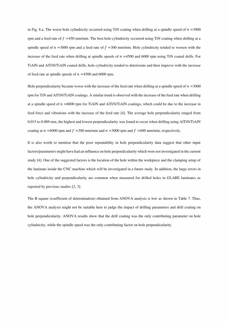
The second type of deformation marks is speculated to be caused by broken fibres which are trapped between the
drill and borehole surface, causing them to be stressed onto the aluminium sheets and plastically deform their
outer surface. In this case, the deformation marks appear to be parallel to the fibres as shown in Fig. 10.a. multiple
instances of this type of marks were observed on the aluminium sheet. Some of the aluminium chips and broken
glass fibres are not evacuated through the drill flutes and are eventually stressed into the edges of the aluminium
sheets or into the voids formed in the glass fibre layers due to fibre pull-outs [50] as shown in Fig. 10.b.
Fig. 10: SEM image of a borehole wall at (a) 𝑓 = 300 mm/min and 𝑛 = 4500 rpm using a AlTiN/TiAlN coated drill (b) at 𝑓 = 300 mm/min and 𝑛 = 6000 rpm for TiAlN coated drill
Interlayer burrs were observed around the borehole and through its thickness which might have caused further
erosion in the glass fibre layers. Besides, the erosion in glass fibre layers might have been caused by the evacuated
metallic chips [3, 50]. Powdery glass fibre chips and broken metallic chips were stressed into the laminate layers
forming what is known as waste material as shown in Fig. 11.a. The waste material -whether metallic or
composite- is caused by the subsequent removal and adherent of laminate constituents materials debris during the
drilling process [3]. The damage in borehole surface increased with the increase of both cutting parameters similar
(a)
(b)

to previously reported studies [3, 50]. The results also showed that the edge of the last aluminium sheet is likely
to be more deteriorated than the first aluminium sheet as reported in Fig. 11.b. This could be attributed to the
increased contact area between the drill and workpiece leading to higher frictional heat and plastic deformation.
Therefore, burr formations tend to be higher at the bottom of the laminate than at the top as reported in previous
literature [2, 3, 50]. The burrs formed at the entry of the hole were uniform around its edge, while burrs formed at
the exit had an irregular appearance and heights.
Delamination (Type I) was present in the machined holes which takes place due to the progression of the drill into
the laminate causing the peeled layers to bend either permanently due to plastic deformation or temporarily like a
cantilever beam [3, 62]. A type II fibre buckling can be seen in Fig. 11.c due to compressive loading acting along
their direction. Some chunks of fibres end with varying lengths were pointing out due to cutting by fracture as
shown in Fig. 11.d [3, 50, 62].

Fig. 11: SEM image of a borehole wall at (a) 𝑓 = 300 mm/min and 𝑛 = 3000 rpm using a AlTiN/TiAlN coated drill (b) the upper and lower aluminium sheets edges at 𝑓 = 300 mm/min and 𝑛 = 3000 rpm using a TiN coated drill (c) 𝑓 = 300 mm/min and 𝑛 = 3000 rpm using a AlTiN/TiAlN coated drill (d) showing fibres with different uncut lengths at 𝑓 = 450 mm/min and 𝑛 =3000 rpm using a TiN coated drill

The SEM images did not show any signs of ply separation in composite layers or de-bonding between the laminate
constituents. It is speculated that the sandwiched glass fibre layers between two metallic sheets from the top and
bottom mimics the effect of support plates placed on the top or the bottom of a composite sample to reduce
delamination, especially when drilling at higher feed rates [3, 63].
4. Conclusions
The machinability of GLARE® fibre metal laminates was investigated using twist drills to analyse the hole size,
circularity, cylindricity and perpendicularity. The objective was to study the influence of drilling and three types
of drill coatings (TiAlN, TiN and AlTiN/TiAlN) on the stated hole quality parameters. The influence of drill
coatings had been previously studied in different GLARE® grades to evaluate the hole quality, but no study was
previously carried out using the same drill geometry. The influence of drill coatings is a crucial factor in drilling
aeronautical multi-materials made from composites and metals since they can prolong drill life and improve
surface finish. However, only a handful number of researches had been conducted on drilling of GLARE®
laminates in general and the influence of drill coating in particular. The following conclusions can be drawn from
the study:
• The thrust force generated using AlTiN/TiAlN multilayer-coated drills was the lowest among the three
coatings tested, followed by TiN and TiAlN coatings, respectively.
• The average reduction in hole size between the top and the bottom region was 15.86 µm, 17.78 µm and
18.19 µm for TiN, TiAlN and AlTiN/TiAlN coated drills, respectively.
• Hole circularity at the bottom was worse than that at the top regardless of drill coating or drilling
parameters. TiN-coated drills produced worst hole circularity at the top among the three coatings.
• Hole cylindricity was worst when using AlTiN/TiAlN and TiN coated drills, whole hole perpendicularity
worsened with the increase of the feed rate.
• The ANOVA results showed that the spindle speed and drill coating had a significant influence on hole
size and circularity, while drill coating was the only contributing parameter on hole cylindricity, and
spindle speed was the only contributing factor on hole perpendicularity.
• SEM inspection showed that the damage generated on the walls of the hole are strongly influenced by
the drilling parameters but not the drill coating. Fibre buckling, smearing, interlayer burr formation and
deformation marks due to evacuated metallic chips and broken glass fibres were observed from the SEM
images.

Acknowledgements
The authors would like to thank Dr Peter J. Kortbeek from DELFT University and the Fibre-Metal Laminate
Centre of Competence (FMLC) for the provision of GLARE® sample. The authors would like to thank Dr Carlton
Byrne and Miss Gabriella Gorey from Cardiff University for assistance with the drilling tests. The authors
acknowledge the support from the European Regional Development Fund through the Welsh Government for
ASTUTE 2020 (Advanced Sustainable Manufacturing Technologies) to facilitate this work.
Data availability
The raw data required to reproduce these findings are available upon request.
References
1. Mouritz, A., Introduction to aerospace materials. 2012: Elsevier. 2. Giasin, K. and S. Ayvar-Soberanis, An Investigation of burrs, chip formation, hole size, circularity and
delamination during drilling operation of GLARE using ANOVA. Composite Structures, 2017. 159: p. 745-760.
3. Giasin, K., Machining Fibre Metal Laminates and Al2024-T3 aluminium alloy. 2017, University of Sheffield.
4. Giasin, K., The effect of drilling parameters, cooling technology, and fiber orientation on hole
perpendicularity error in fiber metal laminates. The International Journal of Advanced Manufacturing Technology, 2018.
5. Hocheng, H., Machining technology for composite materials : principles and practice. 2012, Cambridge, UK; Philadelphia, PA: Woodhead Pub.
6. Giasin, K., S. Ayvar-Soberanis, and A. Hodzic, An experimental study on drilling of unidirectional
GLARE fibre metal laminates. Composite Structures, 2015. 133: p. 794-808. 7. Campbell Jr, F.C., Manufacturing technology for aerospace structural materials. 2011: Elsevier. 8. Vlot, A., Glare: history of the development of a new aircraft material. 2001: Springer Science &
Business Media. 9. Vlot, A. and J.W. Gunnink, Fibre metal laminates: an introduction. 2001: Springer. 10. Gunnink, J., A. Vlot, R. Alderliesten, W. van der Hoeven, A. de Boer, J. Sinke, M. Ypma, T. de Vries,
and T. Wittenberg. Towards technology readiness of fibre metal laminates. in International Congress
of Aeronautical Sciences, 22 nd, Harrogate, United Kingdom. 2000. 11. Vlot, A., L. Vogelesang, and T. De Vries, Towards application of fibre metal laminates in large
aircraft. Aircraft Engineering and Aerospace Technology, 1999. 71(6): p. 558-570. 12. De Graaf, R. and J. Meijer, Laser cutting of metal laminates: analysis and experimental validation.
Journal of Materials Processing Technology, 2000. 103(1): p. 23-28. 13. Geert H.J.J. Roebroeks, P.A.H., Erik J. Kroon,Markus B. Heinimann, The development of central, in
First International Conference on Damage Tolerance of Aircraft Structures, J.S. R. Benedictus, R.C. Alderliesten, J.J. Homan, Editor. 2007: TU Delft, The Netherlands.
14. Elhajjar, R., V. La Saponara, and A. Muliana, Smart Composites: Mechanics and Design. 2013: CRC Press.
15. Seo, H., Damage Tolerance and Durability of GLARE Laminates. 2008: ProQuest. 16. Chawla, K.K., Composite materials: science and engineering. 2012: Springer Science & Business
Media. 17. Baker, A.A., L.F. Rose, and R. Jones, Advances in the bonded composite repair of metallic aircraft
structure. Vol. 1. 2003: Elsevier. 18. Alderliesten, R., On the development of hybrid material concepts for aircraft structures. Recent Patents
on Engineering, 2009. 3(1): p. 25-38. 19. Silberschmidt, V.V., Dynamic deformation, damage and fracture in composite materials and
structures. 2016: Woodhead Publishing.

20. Pora, J., Composite materials in the airbus A380–from history to future. Proceedings of ICCM13, Plenary lecture, CD-ROM, 2001.
21. Sinke, J., Manufacturing of GLARE parts and structures. Applied composite materials, 2003. 10(4-5): p. 293-305.
22. Giasin, K., S. Ayvar-Soberanis, and A. Hodzic, The effects of minimum quantity lubrication and
cryogenic liquid nitrogen cooling on drilled hole quality in GLARE fibre metal laminates. Materials & Design, 2016. 89: p. 996-1006.
23. Giasin, K., S. Ayvar-Soberanis, and A. Hodzic, Evaluation of cryogenic cooling and minimum quantity
lubrication effects on machining GLARE laminates using design of experiments. Journal of Cleaner Production, 2016. 135: p. 533-548.
24. Giasin, K., S. Ayvar-Soberanis, T. French, and V. Phadnis, 3D Finite Element Modelling of Cutting
Forces in Drilling Fibre Metal Laminates and Experimental Hole Quality Analysis. Applied Composite Materials, 2016: p. 1-25.
25. Giasin, K., A. Hodzic, V. Phadnis, and S. Ayvar-Soberanis, Assessment of cutting forces and hole
quality in drilling Al2024 aluminium alloy: experimental and finite element study. The International Journal of Advanced Manufacturing Technology, 2016. 87(5-8): p. 2041-2061.
26. Pawar, O.A., Y.S. Gaikhe, A. Tewari, R. Sundaram, and S.S. Joshi, Analysis of hole quality in drilling
GLARE fiber metal laminates. Composite Structures, 2015. 123: p. 350-365. 27. Tyczynski, P., J. Lemanczyk, and R. Ostrowski, Drilling of CFRP, GFRP, glare type composites.
Aircraft Engineering and Aerospace Technology, 2014. 86(4): p. 312-322. 28. Paul, S., A. Hoogstrate, and R. Van Praag, Abrasive water jet machining of glass fibre metal laminates.
Proceedings of the Institution of Mechanical Engineers, Part B: Journal of Engineering Manufacture, 2002. 216(11): p. 1459-1469.
29. Praag, R.V., Hand drilling fiber metal laminates, guideline for successful hand drilling. Fiber Metal laminates, Handbook of workshop properties, Delft University of Science & Technology, Structures & Materials Laboratory. 1996, Delft University of Science & Technology. 9.
30. Praag, R.V., Milling fiber metal laminate, tool wear tests, edge quality and justification of WP 3-200 to
WP 3-250. Fiber Metal laminates, Handbook of workshop properties, Delft University of Science & Technology, Structures & Materials Laboratory. 1996, Delft University of Science & Technology. 19.
31. van Praag, R. and J. Sinke, Manufacturing fibre-metal laminates: Part 2: The forming properties. 1994, Delft University of Technology.
32. Beumler, T., Flying GLARE: A Contribution to Aircraft Certification Issues in Strength Properties in
Non-damaged and Fatigue Damaged GLARE Structures. 2004: Delft University Press. 33. Kim, D., M. Ramulu, and W. Pedersen, Machinability of titanium/graphite hybrid composites in
drilling. Trans. NAMRI/SME, 2005. 33: p. 445-452. 34. Kim, D. and M. Ramulu, Study on the drilling of titanium/graphite hybrid composites. Journal of
Engineering Materials and Technology, 2007. 129(3): p. 390-396. 35. Kim, G.W. and K.Y. Lee, Critical thrust force at propagation of delamination zone due to drilling of
FRP/metallic strips. Composite structures, 2005. 69(2): p. 137-141. 36. Sánchez Carrilero, M., M. Álvarez, E. Ares, J. Astorga, M. Cano, and M. Marcos. Dry drilling of fiber
metal laminates CF/AA2024. A preliminary study. in Materials science forum. 2006. Trans Tech Publ. 37. Pawar, O.A., Y.S. Gaikhe, A. Tewari, R. Sundaram, and S.S. Joshi, Analysis of hole quality in drilling
GLARE fiber metal laminates. Composite Structures, 2015. 38. Senthilkumar, B.M.A., Mechanical and Machinability Characteristics of Fiber Metal Laminates. 2016:
LAP Lambert Academic Publishing. 60. 39. Rezende, B.A., M.L. Silveira, L.M. Vieira, A.M. Abrão, P.E.d. Faria, and J.C.C. Rubio, Investigation
on the Effect of Drill Geometry and Pilot Holes on Thrust Force and Burr Height When Drilling an
Aluminium/PE Sandwich Material. Materials, 2016. 9(9): p. 774. 40. Devi, G.R. and K. Palanikumar, Analysis on drilling of woven glass fibre reinforced aluminium
sandwich laminates. Journal of Materials Research and Technology, 2018. 41. J.F.W.Coesel, Drilling Of Fibre-Metal Laminates, in Faculty of Aerospace Engineering. 1994, Delft
University of Technology. p. 63. 42. Park, S.Y., W.J. Choi, C.H. Choi, and H.S. Choi, Effect of drilling parameters on hole quality and
delamination of hybrid GLARE laminate. Composite Structures, 2017. 43. Sureshkumar, M., D. Lakshmanan, and A. Murugarajan, Experimental investigation and mathematical
modelling of drilling on GFRP composites. Materials Research Innovations, 2014. 18(S1): p. S1-94-S1-97.
44. Vankanti, V.K. and V. Ganta, Optimization of process parameters in drilling of GFRP composite using
Taguchi method. Journal of Materials Research and Technology, 2014. 3(1): p. 35-41.

45. Krishnaraj, V., A. Prabukarthi, A. Ramanathan, N. Elanghovan, M. Senthil Kumar, R. Zitoune, and J.P. Davim, Optimization of machining parameters at high speed drilling of carbon fiber reinforced plastic
(CFRP) laminates. Composites Part B: Engineering, 2012. 43(4): p. 1791-1799. 46. Ameur, M., M. Habak, M. Kenane, H. Aouici, and M. Cheikh, Machinability analysis of dry drilling of
carbon/epoxy composites: cases of exit delamination and cylindricity error. The International Journal of Advanced Manufacturing Technology, 2017. 88(9-12): p. 2557-2571.
47. Zitoune, R., V. Krishnaraj, and F. Collombet, Study of drilling of composite material and aluminium
stack. Composite Structures, 2010. 92(5): p. 1246-1255. 48. Sreenivasulu, R., Optimization of Burr size, Surface Roughness and Circularity Deviation during
Drilling of Al 6061 using Taguchi Design Method and Artificial Neural Network. Independent Journal of Management & Production, 2015. 6(1): p. 093-108.
49. Giasin, K., G. Gorey, C. Byrne, J. Sinke, and E. Brousseau, Effect of machining parameters and cutting
tool coating on hole quality in dry drilling of fibre metal laminates. Composite Structures, 2019. 50. Giasin, K. and S. Ayvar-Soberanis, Microstructural investigation of drilling induced damage in fibre
metal laminates constituents. Composites Part A: Applied Science and Manufacturing, 2017. 97: p. 166-178.
51. Phadnis, V.A., F. Makhdum, A. Roy, and V.V. Silberschmidt, Drilling in carbon/epoxy composites:
Experimental investigations and finite element implementation. Composites Part A: Applied Science and Manufacturing, 2013. 47: p. 41-51.
52. Dumkum, C., P. Jaritngam, and V. Tangwarodomnukun, Surface characteristics and machining
performance of TiAlN-, TiN-and AlCrN-coated tungsten carbide drills. Proceedings of the Institution of Mechanical Engineers, Part B: Journal of Engineering Manufacture, 2019. 233(4): p. 1075-1086.
53. Abdelhafeez, A.M., S.L. Soo, D.K. Aspinwall, A. Dowson, and D. Arnold, Burr Formation and Hole
Quality when Drilling Titanium and Aluminium Alloys. Procedia CIRP, 2015. 37: p. 230-235. 54. Davim, J.P., Machining composites materials. 2013: John Wiley & Sons. 55. Sultan, A., S. Sharif, and D. Kurniawan, Effect of machining parameters on tool wear and hole quality
of AISI 316L stainless steel in conventional drilling. Procedia Manufacturing, 2015. 2: p. 202-207. 56. Stephenson, D.A. and J.S. Agapiou, Metal cutting theory and practice. Vol. 68. 2005: CRC press. 57. GARDINER, G., Hole quality defined. 2014, compositesworld. 58. SANDVIK, Improved hand-held hole making in composites. 2011: http://www.sandvik.coromant.com. 59. AlSi, I., Effect of cutting parameters on the drilling of AlSi7 metallic foams. Materiali in tehnologije,
2017. 51(1): p. 19-24. 60. Hayajneh, M.T., Hole quality in deep hole drilling. Materials and Manufacturing Processes, 2001.
16(2): p. 147-164. 61. Islam, M.N. and B. Boswell. Effect of cooling methods on hole quality in drilling of aluminium 6061-
6T. in IOP Conference Series: Materials Science and Engineering. 2016. IOP Publishing. 62. Sheikh-Ahmad, J.Y., Machining of polymer composites. 2009: Springer. 63. Tsao, C. and H. Hocheng, Effects of exit back-up on delamination in drilling composite materials using
a saw drill and a core drill. International Journal of Machine Tools and Manufacture, 2005. 45(11): p. 1261-1270.