Title Page and TOC
144
Nothing But Balls Augmented Reality Table Tennis Robot Rensselaer Polytechnic Institute Carl Harding Eric Jacob Brendan Kavanagh Nathaniel Kurczewski Nick Leonard Keith Lim Dominic Lin James Rollo Liam Tallon Robert Van Dyk April 30, 2003
Transcript of Title Page and TOC

Nothing But Balls
Augmented Reality Table Tennis Robot
Rensselaer Polytechnic Institute
Carl Harding Eric Jacob
Brendan Kavanagh Nathaniel Kurczewski
Nick Leonard Keith Lim
Dominic Lin James Rollo Liam Tallon
Robert Van Dyk
April 30, 2003
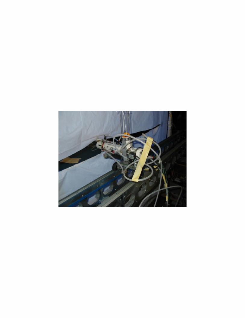

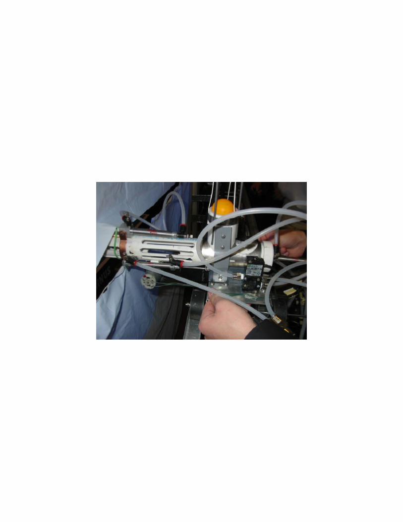

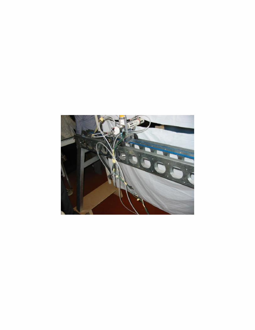
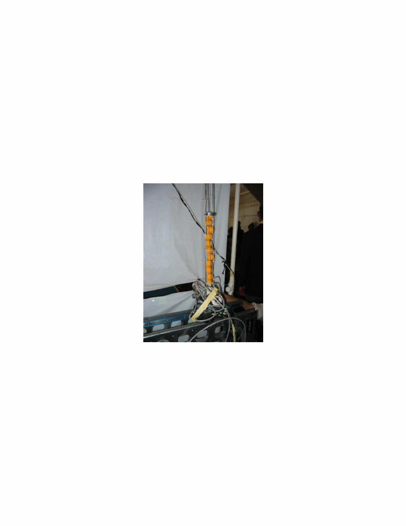


Table of Contents Executive Summary …………………………………………………………………..i List of Figures …………………………………………………………………………. iv List of Tables ……………………………………………………………………………vi Introduction……………………………………………………………………………..vii 1 Augmented Reality (Gus) ………………………………………………………...... 1 1.1 Introduction …………………………………………………………………… .1 1.2 Design Description……………………………………………………………...1 1.3 Bill of Materials………………………………………………………………….6 1.4 Conclusion……………………………………………………………………….6 1.5 Reference………………………………………………………………………..7 2 Mobility and Support…………………………………………………………………8 2.1 Track Assembly…………………………………………………………………8 2.1.1 Introduction………………………………………………………………8 2.1.2 Final Design………………………………………………………………8 2.1.3 Requiremnts and Goals …………………………………………………9 2.1.4 Analytical Development………………………………………………..13 2.1.5 Bill of Material……………………………………………………………15 2.1.6 Conclusion……………………………………………………………….15 2.2 Support Structure……………………………………………………………..16 2.2.1 Introduction………………………………………………………………16 2.2.2 Design Description……………………………………………………..16 2.2.3 Analytical Development………………………………………………..19 2.2.4 Bill of Materials………………………………………………………….20 2.2.5 Conclusion……………………………………………………………….21 2.3 Motor and Pulley………………………………………………………………22 2.3.1 Introduction………………………………………………………………22 2.3.2 Selection Description…………………………………………………...22 2.3.3 Installation………………………………………………………………..28 2.3.4 Bill of Materials…………………………………………………………29 2.3.5 Conclusion……………………………………………………………….29 2.4 Cart……………………………………………………………………………..30 2.4.1 Introduction………………………………………………………………30 2.4.2 Design Description……………………………………………………..30 2.4.3 Bill of Materials………………………………………………………….31 2.4.4 Conclusion……………………………………………………………….32 3 Firing………………………………………………………………………………….33 3.1 Ball Firing Subsystem…………………………………………………………33 3.1.1 Introduction………………………………………………………………33 3.1.2 Design Evolution………………………………………………………..33 3.1.3 Firing System Description Overview………………………………….35 3.1.4 Design Description and Calculations…………………………………37 3.1.4.1 Air Compressor and Rate of Fire……………………………37 3.1.4.2 Pneumatic Piston……………………………………………..38

3.1.4.3 Firing Wheel Assembly…………………………………….40 3.1.4.4 Firing Structure – Barrel, Base and End Cap……………41 3.1.5 Conclusion………………………………………………………………42 3.1.6 Chapter Nomenclature…………………………………………………43 3.1.7 Bill of Materials…………………………………………………………43 3.1.8 References……………………………………………………………..45 3.2 Ball Hopper Assembly………………………………………………………..46 3.2.1 Introduction………………………………………………………………46 3.2.2 The Hopper………………………………………………………………47 3.2.3 The loading of the Ball………………………………………………….48 3.2.4 The Hopper Calculations……………………………………………….50 3.2.5 Bill of Materials…………………………………………………………..51 3.2.6 Conclusion……………………………………………………………….51 3.3 Serving / Lobbing and Spin Assemblies……………………………………53 3.3.1 Serving / Lobbing Assembly…………………………………………..53 3.3.2 Spinning Assembly……………………………………………………..54 4 Computer System Integration……………………………………………………..56 4.1 Computer Programming……………………………………………………..56 4.1.1 Introduction…………..………………………………………………….56 4.1.2 Projector / Video Files………………………………………………….56 4.1.3 The Labjack……………………………………………………………..57 4.1.4 The CMU Cam………………………………………………………….58 4.4.5 Conclusion………………………………………………………………58 4.2 Electronics Integration……………………………………………………….60 4.2.1 Introduction……………………………………………………………..60 4.2.2 Development……………………………………………………………60 4.2.2.1 Wire Requirements…………………………………………..60 4.2.2.2 Support Requirements………………………………………61 4.2.2.3 Shooting Requirements……………………………………..62 4.2.2.4 Choosing Relays and Buffer………………………………..62 4.2.3 Experiments…………………………………………………………….64 4.2.4 Electronics List Bill of Materials………………………………………67 4.2.5 Conclusion………………………………………………………………68 4.3 Sensor using the CMUcam…………………………………………………70 4.3.1 Introduction……………………………………………………………..70 4.3.2 CMUcam Goals and Process………………………………………..70 4.3.3 Communication to the CMUcam……………………………………..74 4.3.4 Flow Chart……………………………………………………………..75 4.3.5 Calculations…………………………………………………………….76 4.3.6 Mounting………………………………………………………………...79 4.3.7 Bill of Materials…………………………………………………………80 4.3.8 Conclusion………………………………………………………………80 4.3.9 References……………………………………………………………..81 Appendix A….....................................................................................................82 Appendix B……………………………………………………………………………85 Appendix C……………………………………………………………………………114

Drawings Tree…………………………………………………………………….120 Drawings……………………………………………………………....................121


i
Executive Summary Dominic Lin
For the spring of 2003 Introduction to Engineering Design course, the professors presented to the students our final project, the Table Tennis Player. Our goal as a team was to “design a machine for a table tennis player to play against,” and this machine would also need to accommodate players of all types including beginners, average players, and players who play at a professional level. In addition, this machine should satisfy the player and give that person a good work out at the same time. Our team, similar to other groups, started the design process by asking ourselves the question, what can we do to improve upon what’s out there already (the state of the art). After researching for a period of time, we came to realize that most of what exist out there accommodates almost everything that a player would need, except one very important aspect. The machine itself is lacking the key feature that it was originally intended to imitate and replace. It wasn’t the ability to hit one spot on the table accurately and precisely, the creation of all types of spin on balls, nor the capacity of balls in the hopper. Instead, these commercial machines omit the essential interactions between two human players during a game of table tennis. These interactions include indication of servicing the ping-pong ball, the return of the ball during game, launching from multiple positions, and the ability to predict the opponent’s next step. Although building a fully functional human robot that can analyze the real-time position of the ball and have the ability to accurately hit and place the ball at a specific location on the table seems impractical and out of reach, we came up with a similar solution that cuts both cost and production time. We decided to take this opportunity and utilize the technology called Augmented Reality (AR) to simulate human play in a game of table tennis. With the combination of video clips, the projector, the variable-positioning firing mechanism, the propulsion technique, sophisticated ball positioning method, and a well written computer program that synchronizes all of the above, we essentially have a system where we could reproduce any action we desire of a real human opponent on the projector screen doing actions such as serving the ball, returning the ball, making comments during a game, or even setting up a tutorial for beginners.

ii
Thus, we separated ourselves into subgroups, structural group, propulsion group, and the controls group, and begun the more in depth design development process. Beginning with the structural group, their goal was to build a structure that would be able to support the variable position track/cart system, the support for the projector screen, and a mount for motion capturing camera (CMU CAM). As requirements set by themselves, they wanted this design to be lightweight, easy to carry around, and strong enough to have a factor of safety more than three. Thus, they have constructed a lightweight metal work bench out of bent sheet steel in combination with several hollow aluminum beams. By using aluminum and cutting out unnecessary materials at varies spots, the whole structure weights surprisingly less than 30 pounds despite its size. The screen structure is composed of pipes made of both PVC and copper, and shower curtains became our projector screen. Finally, the camera mounted at the end of a metal aluminum beam is balanced, with the help of a ball head and counter weight, at the center of the copper pipe that holds the projector screen up. The propulsion group began the process by designing a system where the ping-pong balls would be launched by shots of pressurized air coming from a barrel. However, during the middle of development phase, they ran into aerodynamic problems and decided to launch the ball, while keeping the air propulsion feature, by using the pistons at the end of these solenoid valves to project the ball. Due to clever use of multiple solenoids, this machine can load, stop the excess ball from going into the firing barrel, fire, and reload by utilizing the pressurized air system. Last but not least, the controls group was in charge of how everything functioned together. Since the professor introduced to us the benefits of using National Instruments LabVIEW 6.1, we started out the process by trying the program. However, we soon discover that what we intended to do with our final design may be out of the capability of LabVIEW, especially the integration of our augmented reality system, and thus switched immediately to programming with Java. With Java programming, we were able to send input/output, to and from motors and solenoids, signals using LabJack, capture information coming in from

iii
the CMU CAM, and at the same time project the image of AR opponent on the screen. All together, we have our Augmented Reality table-tennis player. We realize that due to the limited amount of time, resources, and small college student budget, our final design has much room for improvement. We imagine the biggest area of improvement would come in the controls section. First of all, better equipments could be used for the real-time ball capturing system. On our current system, we utilized the camera developed by a group of students at Carnegie Mellon University which captures only up to 17 frames per second. Although an inexpensive and most practical option, the flight of ping-pong balls during an average game tangent the confines of the camera. Also, the camera tracks moving objects by color coding, thus causing a lot of trouble if there’s an interference of colors. Thus, if the tracking of the ping-pong ball could be done by heat tracking or perhaps methods of sound/vibration detection, we could have a system that will have a higher efficiency and processing rate.

iv
List of Figures Figure Description Page Number 1.1 Augmented Reality Video Clip 1 1.2 Screen Placement 2 1.3 Projector Placement 4 1.4 Projector Placement 4 1.5 Projector Placement 4 1.6 Projector Placement 4 1.7 Current Projector Placement/Anlge 4 2.1 Support 8 2.2 Structure Diagram 9 2.3 Sidewall 10 2.4 Beam 11 2.5 Assembly 11 2.6 Rivet Placement 12 2.7 Connectors 12 2.8 Beam 13 2.9 Beam 13 2.10 FBD 14 2.11 Leg 16 2.12 Leg 17 2.13 Leg with hole 17 2.14 Hole Placement 18 2.15 Gusset 18 2.16 Gusset Rivet Locations 19 2.17 FBD 20 2.18 Motor Graph 23 2.19 Motor Picture 24 2.20 Characteristic Curves 25 2.21 Schematic 26 2.22 Pulley Piece 27 2.23 Timing Belt 27 3.1 Airflow around the ball 34 3.2 Barrel 35 3.3 Barrel 36 3.4 Barrel 36 3.5 Barrel 36 3.6 Barrel 37 3.7 Graph 37 3.8 Graph 37 3.9 Bracket FBD 40
v
3.10 Wheel 40 3.11 Barrel 42 3.12 Ball Hopper Assembly 46 3.13 Slide Plate Assembly 48 3.14 Ball Feed Slide Plate 48 3.15 Serve Assembly 53 3.16 Spin Assembly 54 4.1 CMUcam GUI files 58 4.2 Protoboard 61 4.3 Circuit Schematic 63 4.4 CMUcam 71 4.5 CMUcam circuit 71 4.6 CMUcam placement 71 4.7 Projection Lines 72 4.8 CMU Cam Lense Focus 72 4.9 TestProgram 73 4.10 Flow Chart 75 4.11 Table Sections 76 4.12 Table 76 4.13 Coordinates 77 4.14 Picture Dimensions 78 4.15 CMUcam mount 79 4.16 Mounting Dimensions 79

vi
List of Tables
Table Description Page Number 1.1 Projector Placement/Angle 5 1.2 Bill of Materials 6 2.1 Weight Matrix 14 2.3 Bill of Materials 15 2.4 Weight Matrix 20 2.5 Bill of Materials 20 2.6 Bill of Materials 29 2.7 Bill of Materials 31 3.1 Bill of Materials 43 3.2 Bill of Materials 51 4.1 Bill of Materials 67 4.2 Baud Rates 73 4.3 Calculations 78 4.4 Bill of Materials

vii
Introduction Eric Jacob
We are a group of 10 Rensselaer Polytechnic Institute (RPI, located in Troy, NY) students with diverse majors. We have participated in a class at RPI, called Introduction to Engineering Design. This course requires students to perform a task and create a project, using knowledge gained from previous classroom experience. The task given to us was to create a ping pong playing machine capable of competing with the state of the art ping pong playing machines that are currently available on the market today. The usage of this product is to recreate simulated play for the average ping pong playing opponent. The operational capability of our specific project is to create the idea of the ability, functionality of this system. Our system due to financial, time, and knowledge restraints was not designed to be compatible with ping pong players that would rate themselves as advance players.
Starting from Scratch We researched ideas, specifications, and requirements relating to the task at hand. While organizing leadership and design responsibility a project concept was created. This concept was based on three ideas. The first objective was to create an operational shooting device that could perform several main tasks. These tasks included the versatility to be able to simulate serves as well as volleys that an opposing player could use to recreate actual play. The second function was to be able to control the accuracy of the shooting device. The third and final objective was to be able to load the machine consistently, and proficiently. The second objective was to create a support system for the shooting device capable of movement, through a belt driven system. This movement would be focused along the end of the ping pong table, to create the ability of to perform serves and volleys at various positions along the end of the table. The function would only be on one axis, without the versatility to move up and down, exercising a change in height. The support system was created capable of supporting the stresses created from varying forces created by a varying pulley and motor system attached to the support system The third and final objective was to create an augmented reality system that would, act as an actual simulated opponent. With the use of sensors such as a Carnegie Mellon University camera (CMU), and projectors the goal of this system would to sense the location of the return play of an opposing player, to project a simulated image of a player returning. This goal will be completed by integrating the CMU cam with computer programs to project a simulated player on a screen, and create an actual opponent of any individual player. This machine has experience some set backs throughout the creation of it, but in the end is capable of recreating simulated play. Speed, consistency, and continuity of all aspects of this machine have not been manufactured to an exact science so some discrepancy in various areas does occur. Every one of the team members contributed in some fashion to create the finished project. Enjoy what we have created.
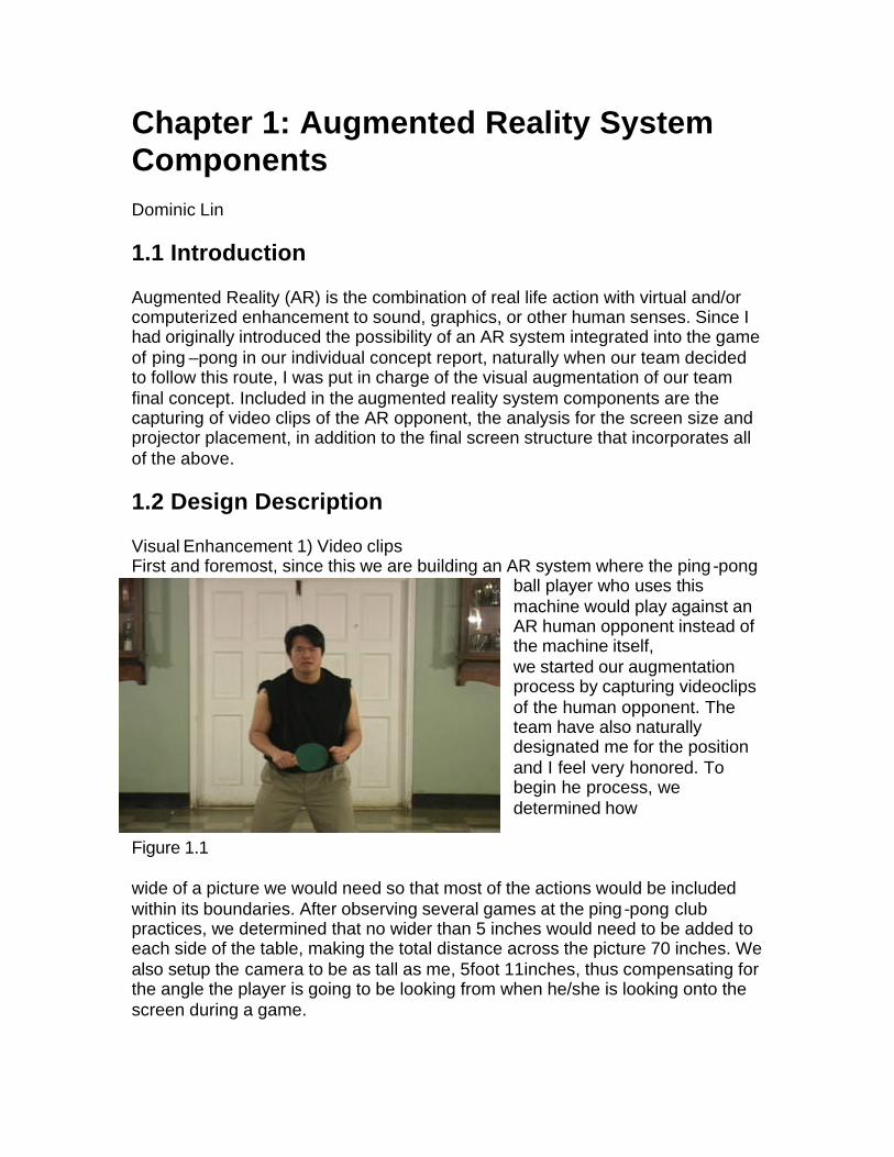
Chapter 1: Augmented Reality System Components Dominic Lin 1.1 Introduction Augmented Reality (AR) is the combination of real life action with virtual and/or computerized enhancement to sound, graphics, or other human senses. Since I had originally introduced the possibility of an AR system integrated into the game of ping –pong in our individual concept report, naturally when our team decided to follow this route, I was put in charge of the visual augmentation of our team final concept. Included in the augmented reality system components are the capturing of video clips of the AR opponent, the analysis for the screen size and projector placement, in addition to the final screen structure that incorporates all of the above. 1.2 Design Description Visual Enhancement 1) Video clips First and foremost, since this we are building an AR system where the ping -pong
ball player who uses this machine would play against an AR human opponent instead of the machine itself, we started our augmentation process by capturing videoclips of the human opponent. The team have also naturally designated me for the position and I feel very honored. To begin he process, we determined how
Figure 1.1 wide of a picture we would need so that most of the actions would be included within its boundaries. After observing several games at the ping -pong club practices, we determined that no wider than 5 inches would need to be added to each side of the table, making the total distance across the picture 70 inches. We also setup the camera to be as tall as me, 5foot 11inches, thus compensating for the angle the player is going to be looking from when he/she is looking onto the screen during a game.

2
The requirements we set for ourselves were as follows. Since this final product have to satisfy a wide range of players who play at different levels, we these videoclips have to include varying speed of both servics and ball returns. We achieve that goal by recording different takes where I would swing in slow motion, some in average speed, and finally some with lightning and frightening speed. Thus depending on the the difficulty the player chooses, he/she might be in for a surprise.
Another requirement we set for ourselves is, unlike the static location of the usual Newgy or the TTmatic machine, to have varying launch locations to provide more realism and variety to this game. Thus, we seperated our clips into 3 areas (right, center, and left). In each location, we made sure that the location I swung at were placed accurately where the ball would be shot out of the launching device thus making the illusion that the AR opponet actualy returns balls. These three locations also had varient speed incorporated so to cover our first requirement. Third requirement, we wanted some form of indication of service of the ping-pong ball so firstly the player can see and predict the AR opponent’s next step and secondly we further satisfy our goal of visual enhancement. We had only included one location for service in this prototype (from leftside of the player), but I imgagin it won’t be hard to include othre postions as our iteration. The launching device at that position recalebrates when the program sigals it to serve instead of return. All this information is sent to and organized by the JAVA program done by Robert. Visual Enhancement 2) Screen Requirement
Figure 1.2
3
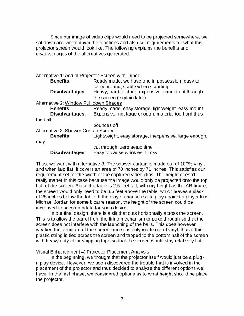
Since our image of video clips would need to be projected somewhere, we sat down and wrote down the functions and also set requirements for what this projector screen would look like. The following explains the benefits and disadvantages of the alternatives generated. Alternative 1: Actual Projector Screen with Tripod
Benefits: Ready made, we have one in possession, easy to carry around, stable when standing.
Disadvantages: Heavy, hard to store, expensive, cannot cut through the screen (explain later)
Alternative 2: Window Pull down Shades Benefits: Ready made, easy storage, lightweight, easy mount Disadvantages: Expensive, not large enough, material too hard thus the ball
bounces off Alternative 3: Shower Curtain Screen Benefits: Lightweight, easy storage, inexpensive, large enough, may
cut through, zero setup time Disadvantages: Easy to cause wrinkles, flimsy Thus, we went with alternative 3. The shower curtain is made out of 100% vinyl, and when laid flat, it covers an area of 70 inches by 71 inches. This satisfies our requirement set for the width of the captured video clips. The height doesn’t really matter in this case because the image would only be projected onto the top half of the screen. Since the table is 2.5 feet tall, with my height as the AR figure, the screen would only need to be 3.5 feet above the table, which leaves a slack of 28 inches below the table. If the player chooses so to play against a player like Michael Jordan for some bizarre reason, the height of the screen could be increased to accommodate for such desire.
In our final design, there is a slit that cuts horizontally across the screen. This is to allow the barrel from the firing mechanism to poke through so that the screen does not interfere with the launching of the balls. This does however weaken the structure of the screen since it is only made out of vinyl, thus a thin plastic string is tied across the screen and tapped to the bottom half of the screen with heavy duty clear shipping tape so that the screen would stay relatively flat. Visual Enhancement 4) Projector Placement Analysis In the beginning, we thought that the projector itself would just be a plug-n-play device. However, we soon discovered the trouble that is involved in the placement of the projector and thus decided to analyze the different options we have. In the first phase, we considered options as to what height should be place the projector.
4
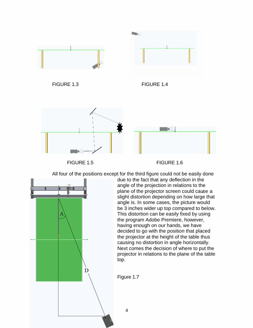
FIGURE 1.3 FIGURE 1.4
FIGURE 1.5 FIGURE 1.6 All four of the positions except for the third figure could not be easily done
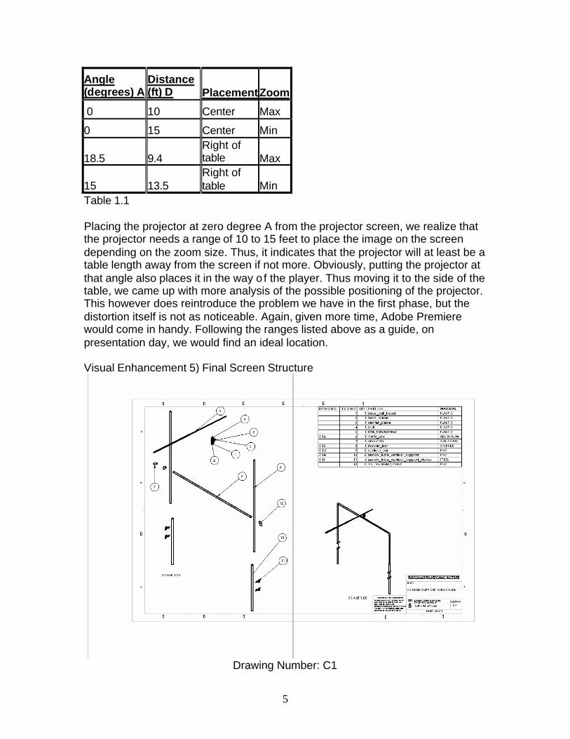
due to the fact that any deflection in the angle of the projection in relations to the plane of the projector screen could cause a slight distortion depending on how large that angle is. In some cases, the picture would be 3 inches wider up top compared to below. This distortion can be easily fixed by using the program Adobe Premiere, however, having enough on our hands, we have decided to go with the position that placed the projector at the height of the table thus causing no distortion in angle horizontally. Next comes the decision of where to put the projector in relations to the plane of the table top. Figure 1.7
5
Angle (degrees) A
Distance (ft) D Placement Zoom
0 10 Center Max
0 15 Center Min
18.5 9.4 Right of table Max
15 13.5 Right of table Min
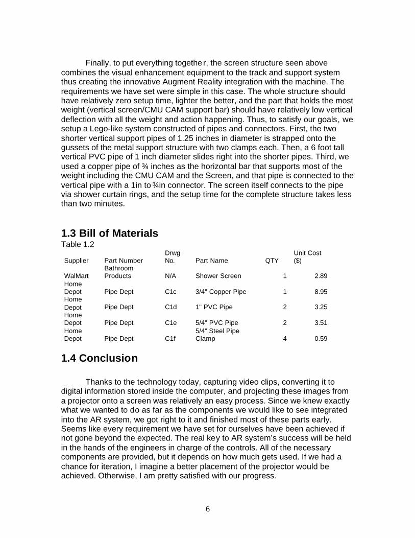
Table 1.1 Placing the projector at zero degree A from the projector screen, we realize that the projector needs a range of 10 to 15 feet to place the image on the screen depending on the zoom size. Thus, it indicates that the projector will at least be a table length away from the screen if not more. Obviously, putting the projector at that angle also places it in the way o f the player. Thus moving it to the side of the table, we came up with more analysis of the possible positioning of the projector. This however does reintroduce the problem we have in the first phase, but the distortion itself is not as noticeable. Again, given more time, Adobe Premiere would come in handy. Following the ranges listed above as a guide, on presentation day, we would find an ideal location. Visual Enhancement 5) Final Screen Structure
Drawing Number: C1
6
Finally, to put everything together, the screen structure seen above combines the visual enhancement equipment to the track and support system thus creating the innovative Augment Reality integration with the machine. The requirements we have set were simple in this case. The whole structure should have relatively zero setup time, lighter the better, and the part that holds the most weight (vertical screen/CMU CAM support bar) should have relatively low vertical deflection with all the weight and action happening. Thus, to satisfy our goals, we setup a Lego-like system constructed of pipes and connectors. First, the two shorter vertical support pipes of 1.25 inches in diameter is strapped onto the gussets of the metal support structure with two clamps each. Then, a 6 foot tall vertical PVC pipe of 1 inch diameter slides right into the shorter pipes. Third, we used a copper pipe of ¾ inches as the horizontal bar that supports most of the weight including the CMU CAM and the Screen, and that pipe is connected to the vertical pipe with a 1in to ¾in connector. The screen itself connects to the pipe via shower curtain rings, and the setup time for the complete structure takes less than two minutes. 1.3 Bill of Materials Table 1.2
Supplier Part Number Drwg No. Part Name QTY
Unit Cost ($)
WalMart Bathroom Products N/A Shower Screen 1 2.89
Home Depot Pipe Dept C1c 3/4" Copper Pipe 1 8.95 Home Depot Pipe Dept C1d 1" PVC Pipe 2 3.25 Home Depot Pipe Dept C1e 5/4" PVC Pipe 2 3.51 Home Depot Pipe Dept C1f
5/4" Steel Pipe Clamp 4 0.59
1.4 Conclusion Thanks to the technology today, capturing video clips, converting it to digital information stored inside the computer, and projecting these images from a projector onto a screen was relatively an easy process. Since we knew exactly what we wanted to do as far as the components we would like to see integrated into the AR system, we got right to it and finished most of these parts early. Seems like every requirement we have set for ourselves have been achieved if not gone beyond the expected. The real key to AR system’s success will be held in the hands of the engineers in charge of the controls. All of the necessary components are provided, but it depends on how much gets used. If we had a chance for iteration, I imagine a better placement of the projector would be achieved. Otherwise, I am pretty satisfied with our progress.

7
1.5 Reference Alok Govil, Suya You, and Ulrich Neumann. “A Video-Based Augmented Reality
Golf Simulator” Comp-Sci Department, Integrated Media System Center, Web Address: http://www.acm.org/sigs/sigmm/MM2000/ep/govi/-demo/: 2000.
8
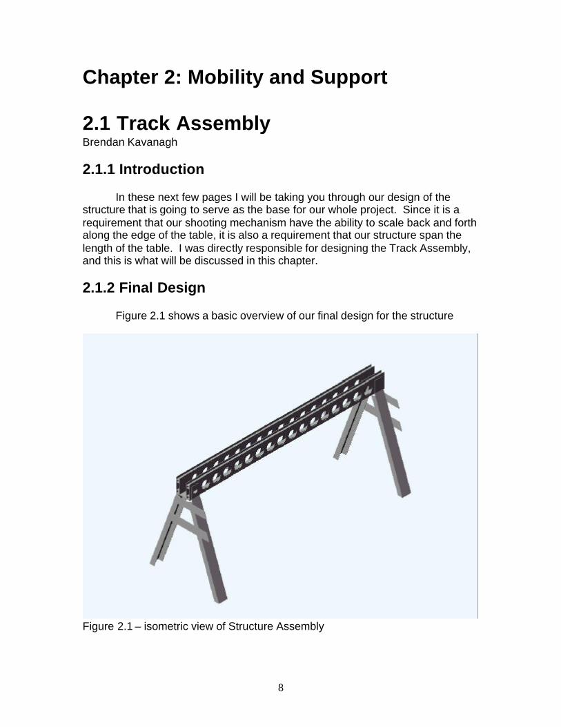
Chapter 2: Mobility and Support 2.1 Track Assembly Brendan Kavanagh 2.1.1 Introduction In these next few pages I will be taking you through our design of the structure that is going to serve as the base for our whole project. Since it is a requirement that our shooting mechanism have the ability to scale back and forth along the edge of the table, it is also a requirement that our structure span the length of the table. I was directly responsible for designing the Track Assembly, and this is what will be discussed in this chapter. 2.1.2 Final Design
Figure 2.1 shows a basic overview of our final design for the structure
Figure 2.1 – isometric view of Structure Assembly
9
This is a steel and aluminum composite structure, the top part of the structure serves as the tracks that the cart will roll back and forth on, and the bottom part consists of the legs holding the track up and the gussets added for strength and for supporting the screen and CMU cam.
2.1.3 Requirements and Goals
• The structure must be able to hold up the weight of the shooting
mechanism and screen supports. • Structure must be light enough for one person to move without
much effort
A closer look at the cross section of the track in fig. 2.2 shows the materials more in depth:
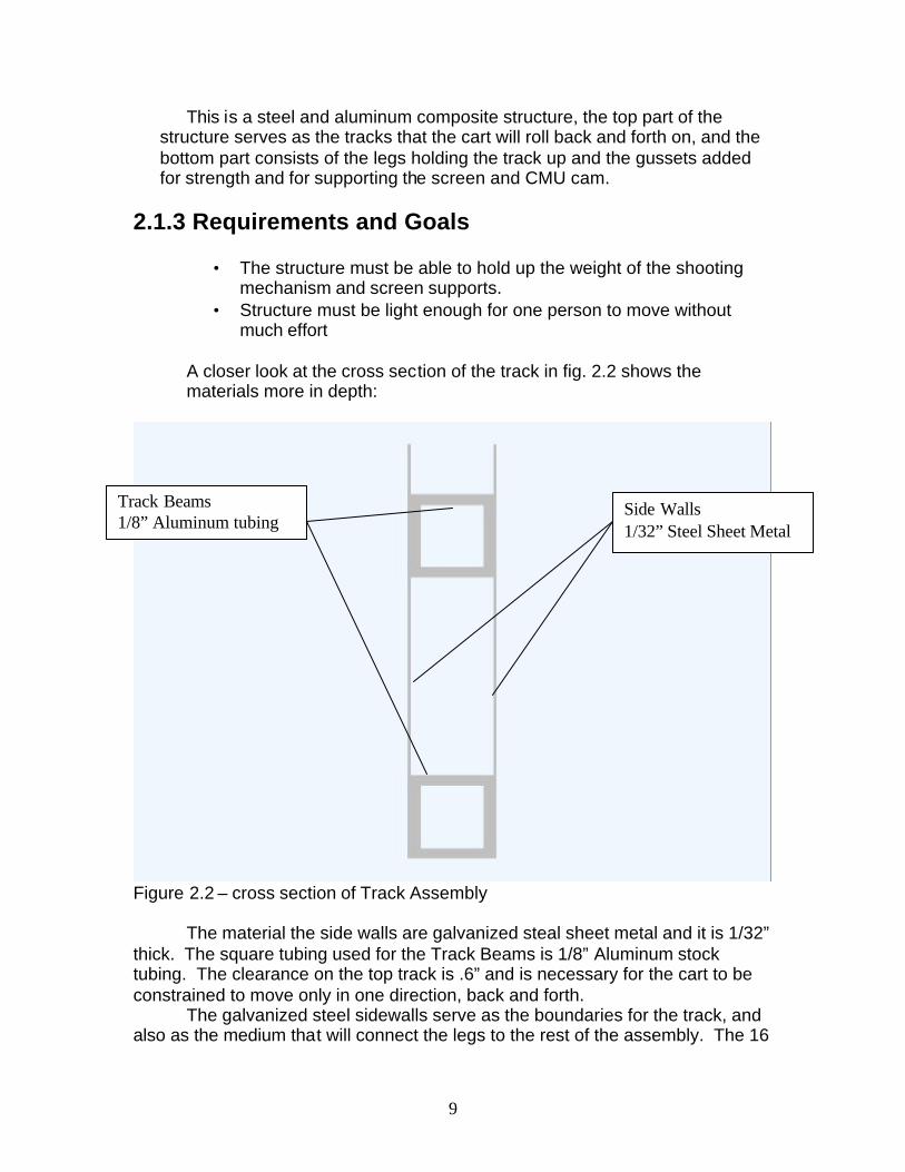
Figure 2.2 – cross section of Track Assembly
The material the side walls are galvanized steal sheet metal and it is 1/32” thick. The square tubing used for the Track Beams is 1/8” Aluminum stock tubing. The clearance on the top track is .6” and is necessary for the cart to be constrained to move only in one direction, back and forth.
The galvanized steel sidewalls serve as the boundaries for the track, and also as the medium that will connect the legs to the rest of the assembly. The 16
Side Walls 1/32” Steel Sheet Metal
Track Beams 1/8” Aluminum tubing
10
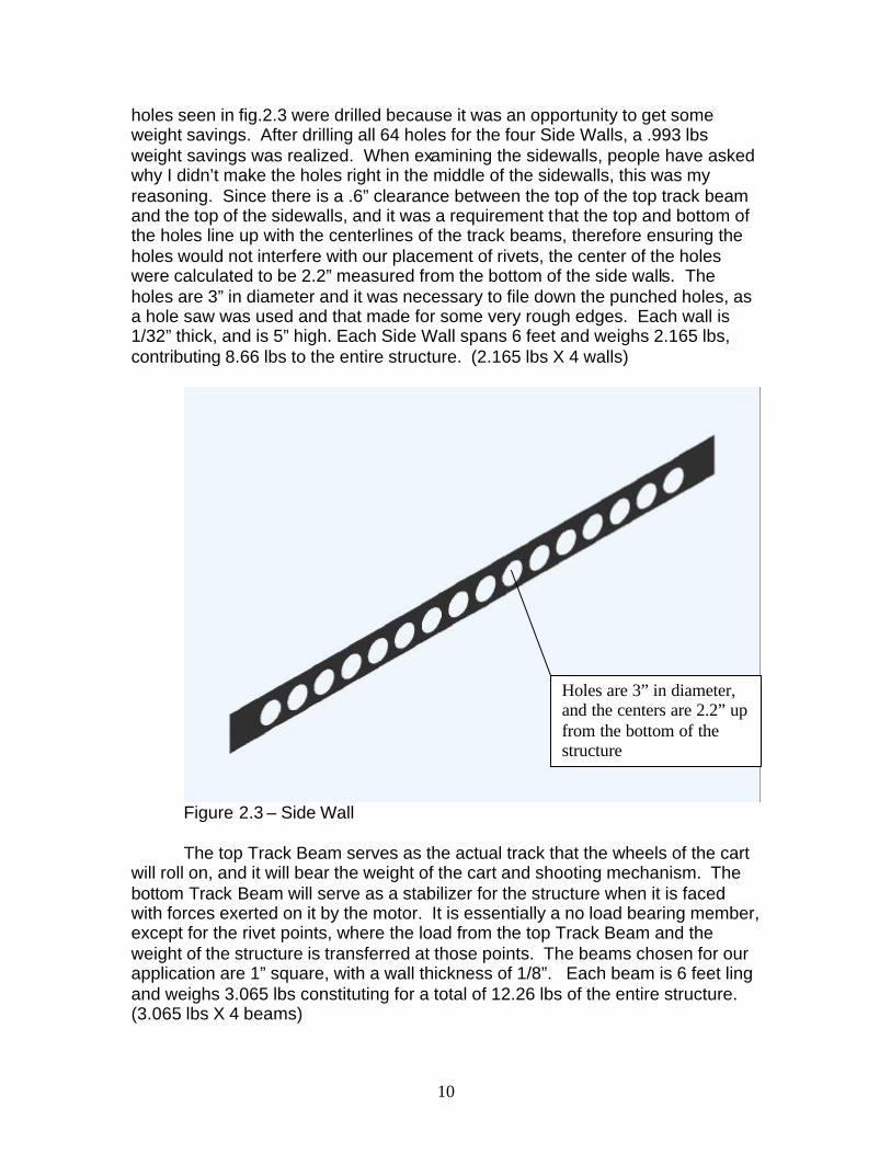
holes seen in fig.2.3 were drilled because it was an opportunity to get some weight savings. After drilling all 64 holes for the four Side Walls, a .993 lbs weight savings was realized. When examining the sidewalls, people have asked why I didn’t make the holes right in the middle of the sidewalls, this was my reasoning. Since there is a .6” clearance between the top of the top track beam and the top of the sidewalls, and it was a requirement that the top and bottom of the holes line up with the centerlines of the track beams, therefore ensuring the holes would not interfere with our placement of rivets, the center of the holes were calculated to be 2.2” measured from the bottom of the side walls. The holes are 3” in diameter and it was necessary to file down the punched holes, as a hole saw was used and that made for some very rough edges. Each wall is 1/32” thick, and is 5” high. Each Side Wall spans 6 feet and weighs 2.165 lbs, contributing 8.66 lbs to the entire structure. (2.165 lbs X 4 walls)
Figure 2.3 – Side Wall
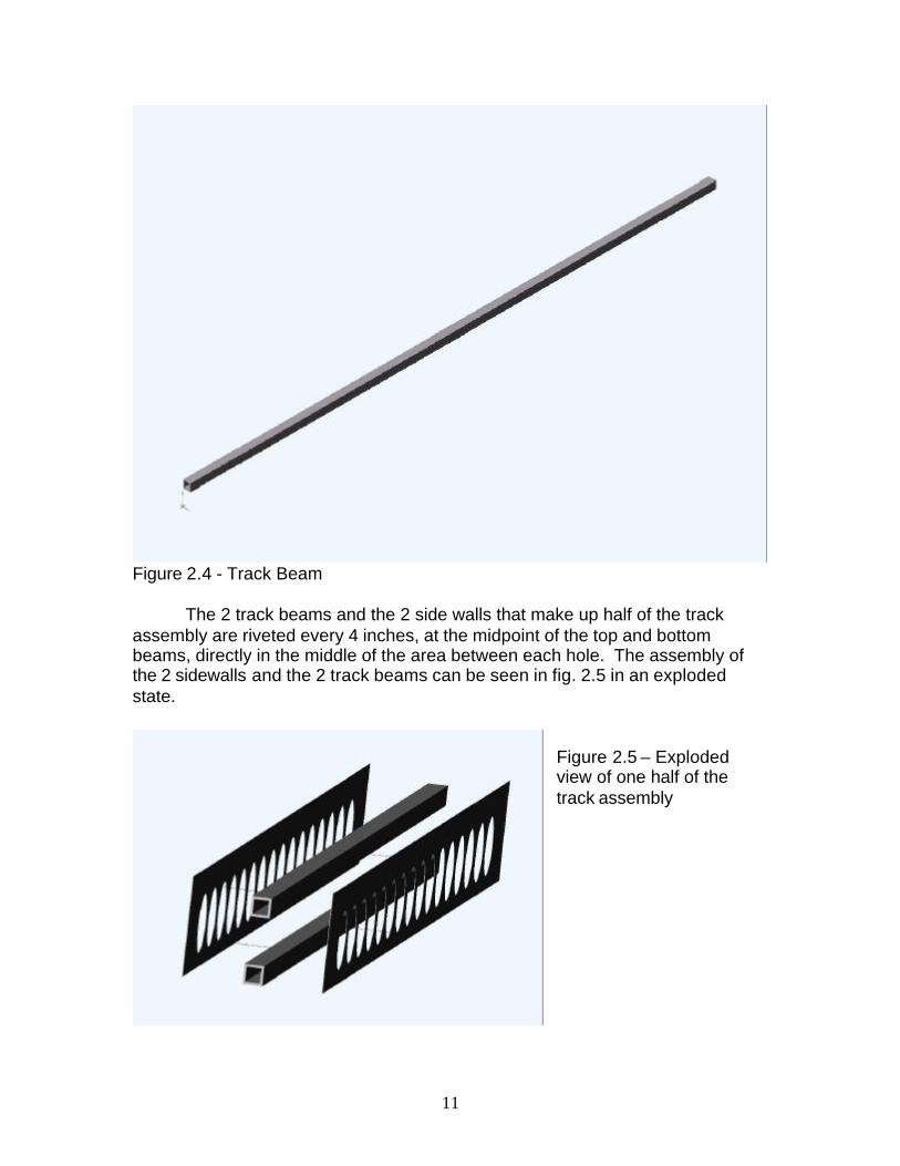
The top Track Beam serves as the actual track that the wheels of the cart will roll on, and it will bear the weight of the cart and shooting mechanism. The bottom Track Beam will serve as a stabilizer for the structure when it is faced with forces exerted on it by the motor. It is essentially a no load bearing member, except for the rivet points, where the load from the top Track Beam and the weight of the structure is transferred at those points. The beams chosen for our application are 1” square, with a wall thickness of 1/8”. Each beam is 6 feet ling and weighs 3.065 lbs constituting for a total of 12.26 lbs of the entire structure. (3.065 lbs X 4 beams)
Holes are 3” in diameter, and the centers are 2.2” up from the bottom of the structure
11
Figure 2.4 - Track Beam
The 2 track beams and the 2 side walls that make up half of the track assembly are riveted every 4 inches, at the midpoint of the top and bottom beams, directly in the middle of the area between each hole. The assembly of the 2 sidewalls and the 2 track beams can be seen in fig. 2.5 in an exploded state.
Figure 2.5 – Exploded view of one half of the track assembly

12
After the fabrication of the two components of the assembly was complete,
a means of connecting the two was necessary to figure out. Four connecting members were chosen from stock Aluminum, two of which have 90° bends to added stiffness, See fig. 2.7. Since the members were only going to be essentially pin jointed, it was necessary to have two of the members opposing each other in a triangle fashion. It was decided to use the two members with the bends to have opposing each other, making it even that much more ridged. The bent members weigh .516 lbs each, contributing 1.03lbs to the entire assembly. The simpler design of the members serve as the perpendicular supports. These weigh .255 lbs each, contributing .51lbs to the whole assembly.
Figure 2.7 – Isometric view of triangled member and perpendicular member
Rivet point on top beam
Rivets on the bottom beam are placed in a similar fashion, simply mirrored about the center of the holes
Figure 2.6 – side view of Track Assembly showing rivet placement
13
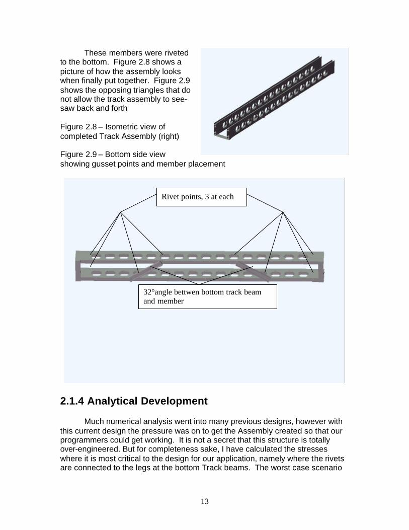
These members were riveted to the bottom. Figure 2.8 shows a picture of how the assembly looks when finally put together. Figure 2.9 shows the opposing triangles that do not allow the track assembly to see-saw back and forth
Figure 2.8 – Isometric view of completed Track Assembly (right)
Figure 2.9 – Bottom side view showing gusset points and member placement
2.1.4 Analytical Development Much numerical analysis went into many previous designs, however with this current design the pressure was on to get the Assembly created so that our programmers could get working. It is not a secret that this structure is totally over-engineered. But for completeness sake, I have calculated the stresses where it is most critical to the design for our application, namely where the rivets are connected to the legs at the bottom Track beams. The worst case scenario
32°angle bettwen bottom track beam and member
Rivet points, 3 at each
14
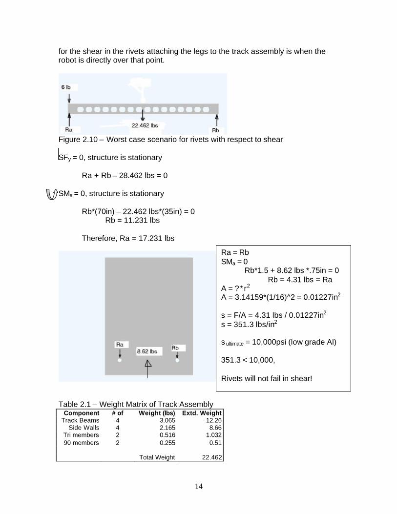
for the shear in the rivets attaching the legs to the track assembly is when the robot is directly over that point.
Figure 2.10 – Worst case scenario for rivets with respect to shear SFy = 0, structure is stationary
Ra + Rb – 28.462 lbs = 0 SMa = 0, structure is stationary
Rb*(70in) – 22.462 lbs*(35in) = 0 Rb = 11.231 lbs Therefore, Ra = 17.231 lbs
Table 2.1 – Weight Matrix of Track Assembly
Component # of Weight (lbs) Extd. Weight Track Beams 4 3.065 12.26
Side Walls 4 2.165 8.66 Tri members 2 0.516 1.032 90 members 2 0.255 0.51
Total Weight 22.462
Ra = Rb SMa = 0 Rb*1.5 + 8.62 lbs *.75in = 0 Rb = 4.31 lbs = Ra A = ?* r2
A = 3.14159*(1/16)^2 = 0.01227in2
s = F/A = 4.31 lbs / 0.01227in2
s = 351.3 lbs/in2
s ultimate = 10,000psi (low grade Al) 351.3 < 10,000, Rivets will not fail in shear!
15
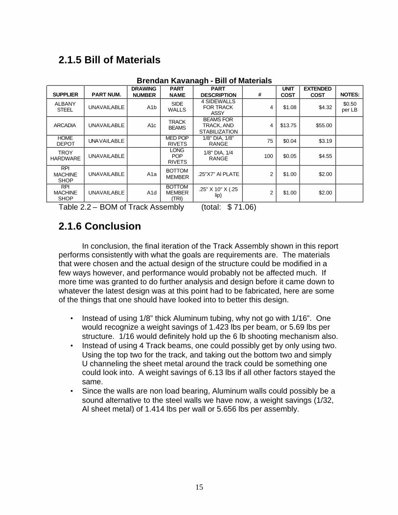
2.1.5 Bill of Materials
Brendan Kavanagh - Bill of Materials
SUPPLIER PART NUM. DRAWING NUMBER
PART NAME
PART DESCRIPTION #
UNIT COST
EXTENDED COST NOTES:
ALBANY STEEL UNAVAILABLE A1b
SIDE WALLS
4 SIDEWALLS FOR TRACK
ASSY 4 $1.08 $4.32
$0.50 per LB
ARCADIA UNAVAILABLE A1c TRACK BEAMS
BEAMS FOR TRACK, AND
STABILIZATION 4 $13.75 $55.00
HOME DEPOT UNAVAILABLE MED POP
RIVETS 1/8" DIA, 1/8"
RANGE 75 $0.04 $3.19
TROY HARDWARE UNAVAILABLE
LONG POP
RIVETS
1/8" DIA, 1/4 RANGE 100 $0.05 $4.55
RPI MACHINE
SHOP UNAVAILABLE A1a
BOTTOM MEMBER .25"X7" Al PLATE 2 $1.00 $2.00
RPI MACHINE
SHOP UNAVAILABLE A1d
BOTTOM MEMBER
(TRI)
.25" X 10" X (.25 lip) 2 $1.00 $2.00
Table 2.2 – BOM of Track Assembly (total: $ 71.06)
2.1.6 Conclusion In conclusion, the final iteration of the Track Assembly shown in this report performs consistently with what the goals are requirements are. The materials that were chosen and the actual design of the structure could be modified in a few ways however, and performance would probably not be affected much. If more time was granted to do further analysis and design before it came down to whatever the latest design was at this point had to be fabricated, here are some of the things that one should have looked into to better this design.
• Instead of using 1/8” thick Aluminum tubing, why not go with 1/16”. One would recognize a weight savings of 1.423 lbs per beam, or 5.69 lbs per structure. 1/16 would definitely hold up the 6 lb shooting mechanism also.
• Instead of using 4 Track beams, one could possibly get by only using two. Using the top two for the track, and taking out the bottom two and simply U channeling the sheet metal around the track could be something one could look into. A weight savings of 6.13 lbs if all other factors stayed the same.
• Since the walls are non load bearing, Aluminum walls could possibly be a sound alternative to the steel walls we have now, a weight savings (1/32, Al sheet metal) of 1.414 lbs per wall or 5.656 lbs per assembly.
16
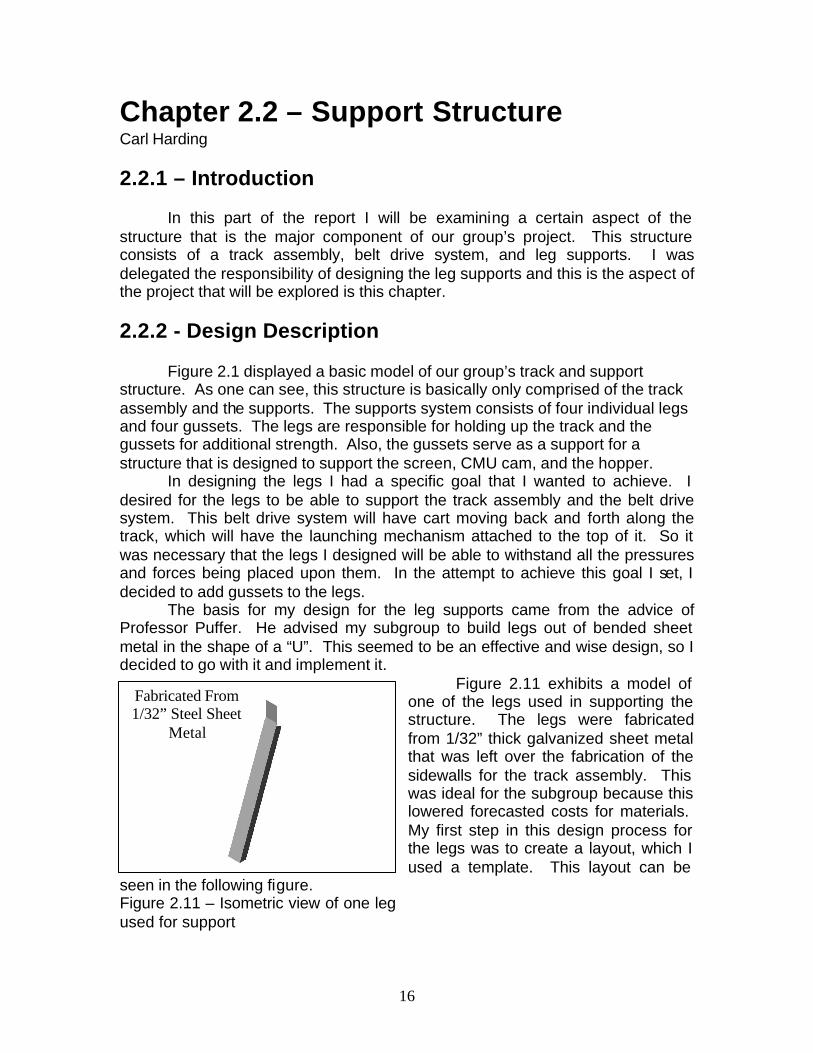
Chapter 2.2 – Support Structure Carl Harding 2.2.1 – Introduction In this part of the report I will be examining a certain aspect of the structure that is the major component of our group’s project. This structure consists of a track assembly, belt drive system, and leg supports. I was delegated the responsibility of designing the leg supports and this is the aspect of the project that will be explored is this chapter. 2.2.2 - Design Description Figure 2.1 displayed a basic model of our group’s track and support structure. As one can see, this structure is basically only comprised of the track assembly and the supports. The supports system consists of four individual legs and four gussets. The legs are responsible for holding up the track and the gussets for additional strength. Also, the gussets serve as a support for a structure that is designed to support the screen, CMU cam, and the hopper. In designing the legs I had a specific goal that I wanted to achieve. I desired for the legs to be able to support the track assembly and the belt drive system. This belt drive system will have cart moving back and forth along the track, which will have the launching mechanism attached to the top of it. So it was necessary that the legs I designed will be able to withstand all the pressures and forces being placed upon them. In the attempt to achieve this goal I set, I decided to add gussets to the legs. The basis for my design for the leg supports came from the advice of Professor Puffer. He advised my subgroup to build legs out of bended sheet metal in the shape of a “U”. This seemed to be an effective and wise design, so I decided to go with it and implement it.
Figure 2.11 exhibits a model of one of the legs used in supporting the structure. The legs were fabricated from 1/32” thick galvanized sheet metal that was left over the fabrication of the sidewalls for the track assembly. This was ideal for the subgroup because this lowered forecasted costs for materials. My first step in this design process for the legs was to create a layout, which I used a template. This layout can be
seen in the following figure. Figure 2.11 – Isometric view of one leg used for support
Fabricated From 1/32” Steel Sheet
Metal
17
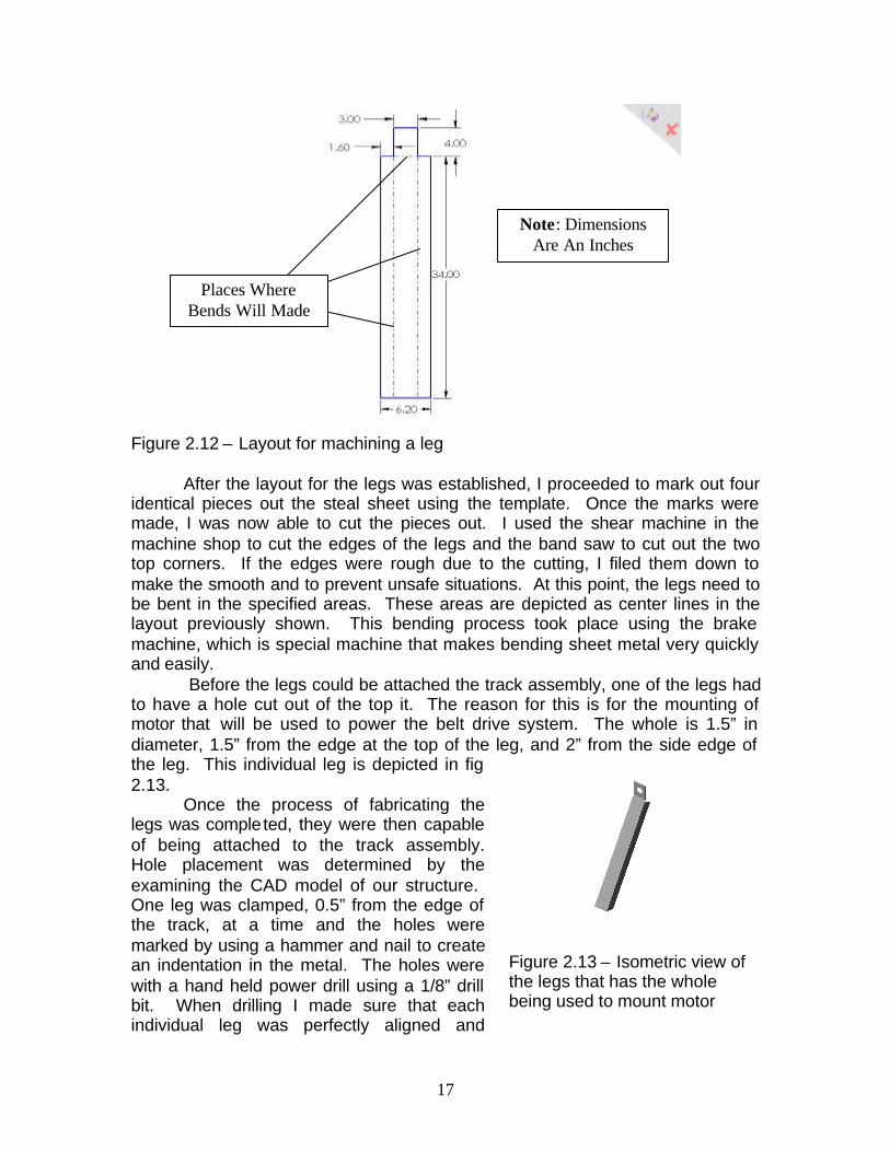
Figure 2.12 – Layout for machining a leg
After the layout for the legs was established, I proceeded to mark out four
identical pieces out the steal sheet using the template. Once the marks were made, I was now able to cut the pieces out. I used the shear machine in the machine shop to cut the edges of the legs and the band saw to cut out the two top corners. If the edges were rough due to the cutting, I filed them down to make the smooth and to prevent unsafe situations. At this point, the legs need to be bent in the specified areas. These areas are depicted as center lines in the layout previously shown. This bending process took place using the brake machine, which is special machine that makes bending sheet metal very quickly and easily. Before the legs could be attached the track assembly, one of the legs had to have a hole cut out of the top it. The reason for this is for the mounting of motor that will be used to power the belt drive system. The whole is 1.5” in diameter, 1.5” from the edge at the top of the leg, and 2” from the side edge of the leg. This individual leg is depicted in fig 2.13. Once the process of fabricating the legs was completed, they were then capable of being attached to the track assembly. Hole placement was determined by the examining the CAD model of our structure. One leg was clamped, 0.5” from the edge of the track, at a time and the holes were marked by using a hammer and nail to create an indentation in the metal. The holes were with a hand held power drill using a 1/8” drill bit. When drilling I made sure that each individual leg was perfectly aligned and
Places Where Bends Will Made
Note: Dimensions Are An Inches
Figure 2.13 – Isometric view of the legs that has the whole being used to mount motor
18
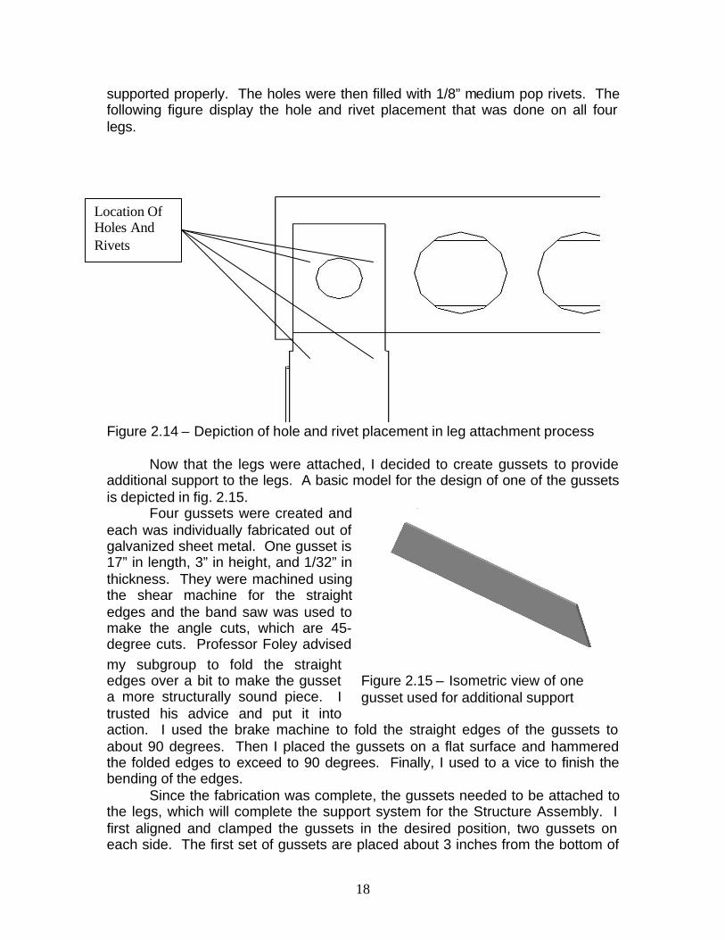
supported properly. The holes were then filled with 1/8” medium pop rivets. The following figure display the hole and rivet placement that was done on all four legs.
Figure 2.14 – Depiction of hole and rivet placement in leg attachment process
Now that the legs were attached, I decided to create gussets to provide additional support to the legs. A basic model for the design of one of the gussets is depicted in fig. 2.15.
Four gussets were created and each was individually fabricated out of galvanized sheet metal. One gusset is 17” in length, 3” in height, and 1/32” in thickness. They were machined using the shear machine for the straight edges and the band saw was used to make the angle cuts, which are 45-degree cuts. Professor Foley advised my subgroup to fold the straight edges over a bit to make the gusset a more structurally sound piece. I trusted his advice and put it into action. I used the brake machine to fold the straight edges of the gussets to about 90 degrees. Then I placed the gussets on a flat surface and hammered the folded edges to exceed to 90 degrees. Finally, I used to a vice to finish the bending of the edges. Since the fabrication was complete, the gussets needed to be attached to the legs, which will complete the support system for the Structure Assembly. I first aligned and clamped the gussets in the desired position, two gussets on each side. The first set of gussets are placed about 3 inches from the bottom of
Location Of Holes And Rivets
Figure 2.15 – Isometric view of one gusset used for additional support
19
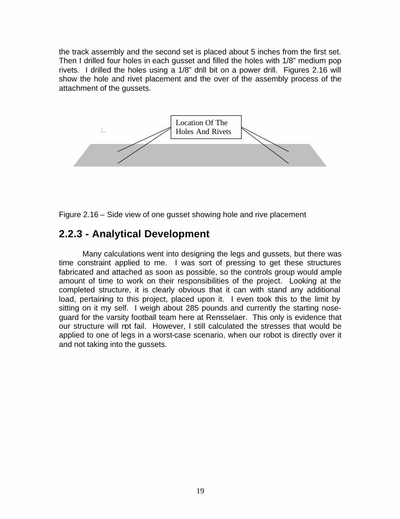
the track assembly and the second set is placed about 5 inches from the first set. Then I drilled four holes in each gusset and filled the holes with 1/8” medium pop rivets. I drilled the holes using a 1/8” drill bit on a power drill. Figures 2.16 will show the hole and rivet placement and the over of the assembly process of the attachment of the gussets.
Figure 2.16 – Side view of one gusset showing hole and rive placement
2.2.3 - Analytical Development Many calculations went into designing the legs and gussets, but there was time constraint applied to me. I was sort of pressing to get these structures fabricated and attached as soon as possible, so the controls group would ample amount of time to work on their responsibilities of the project. Looking at the completed structure, it is clearly obvious that it can with stand any additional load, pertaining to this project, placed upon it. I even took this to the limit by sitting on it my self. I weigh about 285 pounds and currently the starting nose-guard for the varsity football team here at Rensselaer. This only is evidence that our structure will not fail. However, I still calculated the stresses that would be applied to one of legs in a worst-case scenario, when our robot is directly over it and not taking into the gussets.
Location Of The Holes And Rivets

20
6 lb
6 lb Figure 2.17 – worst-case scenario for one leg with respect to shear Table 2.4 - Weight matrix for this system
Component Quantity Weight (lbs) Extended Weight Leg 4 5.314 21.256
Gusset 4 0.937 3.748 Total Weight = 25.004 lbs 2.2.4 - Bill Of Materials Table 2.5 - Bill of Materials
Supplier Part Num.
Drawing Number
Part Name
Part Description #
Unit Cost
Extended Cost Notes
ALBANY STEEL N/A A1e LEG
4 LEGS FOR SUPPORT OF
TRACK ASSEMBLY AND BELT
DRIVE SYSTEM
4 $2.66 $10.64 $0.50/lb
ALBANY STEEL N/A A1d GUSSET
4 GUSSETS TO PROVIDE
ADDITIONAL STRENGTH TO
LEGS
4 $0.47 $1.87 $0.50/lb
HOME DEPOT N/A
MEDIUM POP
RIVETS
1/8” DIAMETER, 1/8” RANGE 32 $0.04 $1.28
Point Where Stress Is Experienced the Most Due To Bending
Area Of This Cross Section Is 0.09375in2
σ = F/A σ = 6 lb / 0.09375in2
σ = 64 lbs/ in2
σUltimate = 21 ksi (low grade of steel)
64 lbs/ in2 < 21 ksi
Therefore, the legs will not fail in shear.
21
2.2.5 - Conclusion In conclusion, the final design and fabrication of the support system for the major structure for the group’s project meets the entire goal I set before the design process began. The legs and gussets support the structure adequately and with stand any additional load added that pertains to the project. I even sat on the structure when it was completed and the structure did not cause any negative effects on the structure. That alone clearly demonstrates the success the legs and gussets have reached. If allocated more time I would make one adjustment to my design of the legs. It came to my attention, with the help of Professor Foley, that the top piece of the leg that attached to the side of the track should have been longer. The reason for this is because the bottom hole and rivets penetrate the panel and beam of the track; however, the top ones on two legs do not. This will cause the legs to pull on the panels if an extreme amount of weight is applied to the structure.

22

22
2.3 Motor and Pulley Nick Leonard 2.3.1 Introduction The following chapter is devoted to the explanation of the requirement analysis, the selection, and the mechanical logistics. The motor described here is the motivator for the cart’s movement along the tracks. There were several electrical constraints placed by the course, the most applicable to this area was the limitation to a maximum of 24 V, for the safety of the system. The requirements set up by the team were much more defining: If possible, it would simplify the electrical team’s work to have a 12 V system, but more importantly it must not consume much amperage, due to the cost of an appropriate power supply. From the mechanical requirements, the team decided to aim high and attempt to have the cart be able to traverse the full five-foot range in a mere 1.5 seconds. This expectation, together with the low amperage draw, stood out in my mind as the most challenging. 2.3.2 Selection Description In order to begin the search for the appropriate motor, I needed to procure some ball park numbers that would define the motor’s requirements. The first and most important was the output power, but that had to be qualified. Since the components of power are RPM and torque, and since we would need a particular combination of those with relatively small ranges of variation, I decided to pick RPM as the first variable to seek. The motor is attached to its load, the cart via a pulley, and I intentionally left the diameter of the pulley variable, to ease the constraints between the variables torque and RPM. The first step was to determine what loadings would be placed on the motor, in the worst possible case: the acceleration phase of a five foot run from rest. The loading on the motor arises from several sources, including mass of the cart, friction between the cart and the track, internal friction in the motor, and rotational inertia both in the motor and the pulley. At this early stage, it was impossible to speculate on the internal friction and the rotational inertias, so I added a safety factor. The summation is presented below:
SF = mca + µmcg + 25% The mass of the cart was obtained from the launching team as 4 pounds, and I rounded it off for good measure. After a brief discussion with my professor, I decided that coefficient of friction between the rubber wheels and the aluminum track would safely be set at µ = .05. The acceleration was obtained by setting a motion profile in the shape of a trapezoid (See Figure 2.18).

23
Figure 2.18
I made an assumption and set the actual acceleration tie at only .3 s, an admittedly ambitious number for our goals. After an attempt at using algebraic kinematics, I realized that the problem was indeterminate and used the fact that the integral of the total area had to equal the total distance traveled which was known to be five feet. The result was a maximum velocity of 4.4 ft/s, and an according acceleration of 9.88 ft/s2.
With this found, the load on the motor could be calculated, and the result was 1.794 ft*lbf/s2. At this point, I had a load, and a maximum velocity which had to be reached, all the requirements to start to size the appropriate pulley. I started by picking an arbitrary size, a two inch diameter pulley. The result was a torque of 28.69 in*oz at 509.3 RPM. The power associated with this combination (and any other combination so long as RPM and torque remained inverse to each other) was in the ball park of .15 hp.
Armed with some rudimentary calculations, Liam of the electrical team and I spent a few hours browsing the internet, looking for suitable motors. It quickly became apparent that while all manner of power motors were to be found, many of them, such as brushless DC, were operating at tens of thousands of RPM with relatively little torque. Indeed, we realized that we were looking for “gearmotors” with an integral gearbox attached. And no common motor, as our particular combination of requirements in torque and RPM were fairly high end. I quickly learned that a 2” diameter pulley would not work with any of the motors we found; we would have to use 4” at the least, with according requirements of 57.38 in*oz
24
of torque and 254.65 RPM. A 6” pulley was even more appealing, but it would have infringed on a design consideration on the support structure.
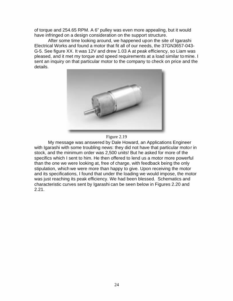
After some time looking around, we happened upon the site of Igarashi Electrical Works and found a motor that fit all of our needs, the 37GN3657-043-G-5. See figure XX. It was 12V and drew 1.03 A at peak efficiency, so Liam was pleased, and it met my torque and speed requirements at a load similar to mine. I sent an inquiry on that particular motor to the company to check on price and the details.
Figure 2.19
My message was answered by Dale Howard, an Applications Engineer with Igarashi with some troubling news: they did not have that particular motor in stock, and the minimum order was 2,500 units! But he asked for more of the specifics which I sent to him. He then offered to lend us a motor more powerful than the one we were looking at, free of charge, with feedback being the only stipulation, which we were more than happy to give. Upon receiving the motor and its specifications, I found that under the loading we would impose, the motor was just reaching its peak efficiency. We had been blessed. Schematics and characteristic curves sent by Igarashi can be seen below in Figures 2.20 and 2.21.

25
Figure 2.20 – Characteristic Curves
26
Figure 2.21 - Schematic
27
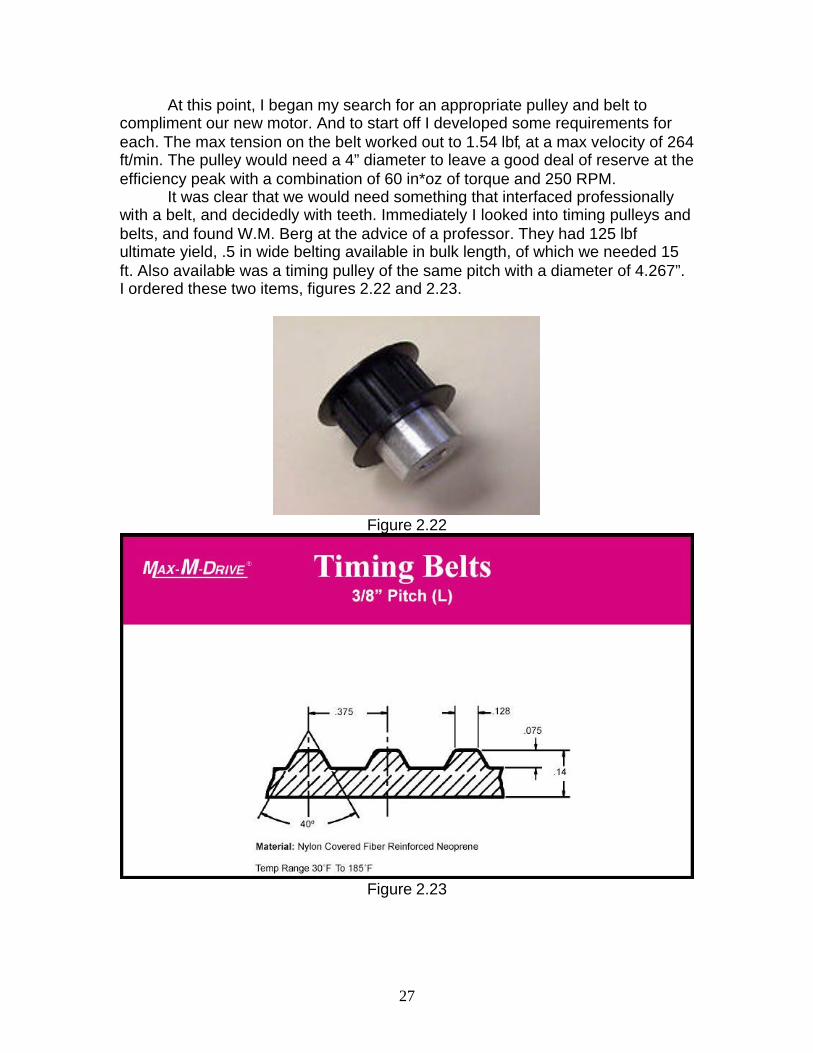
At this point, I began my search for an appropriate pulley and belt to compliment our new motor. And to start off I developed some requirements for each. The max tension on the belt worked out to 1.54 lbf, at a max velocity of 264 ft/min. The pulley would need a 4” diameter to leave a good deal of reserve at the efficiency peak with a combination of 60 in*oz of torque and 250 RPM.
It was clear that we would need something that interfaced professionally with a belt, and decidedly with teeth. Immediately I looked into timing pulleys and belts, and found W.M. Berg at the advice of a professor. They had 125 lbf ultimate yield, .5 in wide belting available in bulk length, of which we needed 15 ft. Also available was a timing pulley of the same pitch with a diameter of 4.267”. I ordered these two items, figures 2.22 and 2.23.
Figure 2.22
Figure 2.23

28
2.3.3 Installation
Weeks later I mounted the motor to the support, using cursed metric Allen screws and a simple backing plate against the inner wall of the forward track assembly. I reinforced the 1/32 galvanized steel with another layer, attached to the aluminum beams to provide a more sound moment resistance to the motor’s torque.
The most notable task was the fabrication of a bushing and the preparation of the pulley’s hub. The output shaft of the motor was considerably less in length than the depth of the hub of the pulley, and length was constrained directly by the location of the through screw. In order to minimize the moment produced (90? from the rotational axis of the shaft), the hub of the pulley had to be milled down to its minimum depth without infringing on the plastic structure, and this was done on a CNC machine with the professor’s help. The numbers were now in existence to allow the creation of the bushing, which was turned out of .5” diameter aluminum rod stock. It was made to extend the full depth of the pulley hub for maximum contact area, and was glued in but extra grip. Again with the aid of my professor, the delicate task of drilling the through screw hole in the pulley hub was accomplished.
The final element that was fabricated for this subsystem was the freewheeling pulley to provide the second point of support for the belt. Rather than pay another $35 dollars for a second timing pulley, it was decided to simply turn an approximate facsimile out of aluminum. Nate was responsible for the time on the lathe, and Liam had a hand in the assembly. This wheel did not need teeth, as it was not under translational loading from the motion of the cart, its only task in life was to freewheel.
The assembly was smooth. The pulley was attached to the shaft of the motor with almost no difficulty. The free wheeling pulley was very simply mounted to the opposite end of the support, and with the addition of the cart, the belt was snugly fitted into place.
29
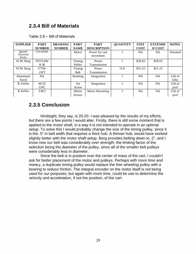
2.3.4 Bill of Materials Table 2.6 – Bill of Materials
2.3.5 Conclusion
Hindsight, they say, is 20-20. I was pleased by the results of my efforts, but there are a few points I would alter. Firstly, there is still some moment that is applied to the motor shaft, in a way it is not intended to operate in an optimal setup. To solve this I would probably change the size of the timing pulley, since it is the .5” in belt width that requires a thick hub. A thinner hub, would have worked slightly better with the motor shaft setup. Berg provides belting down to .2”, and I know now our belt was considerably over strength, the limiting factor of the selection being the diameter of the pulley, since all of the smaller belt pulleys were considerably less in diameter.
Since the belt is in position over the center of mass of the cart, I couldn’t ask for better placement of the motor and pulleys. Perhaps with more time and money, a duplicate timing pulley would replace the free wheeling pulley with a bearing to reduce friction. The integral encoder on the motor itself is not being used for our purposes, but again with more time, could be use to determine the velocity and acceleration, if not the position, of the cart.
SUPPLIER PART NUMBER
DRAWING NUMBER
PART NAME
PART DESCRIPTION
QUANTITY UNIT COST
EXTENDED COST
NOTES
Igarashi Electrical
Works
Unavailable Motor Power for cart movement
1 NA NA Donated
W.M. Berg TP37L8W8-36
Timing Pulley
Power Transmission
1 $38.65 $38.65
W.M. Berg 37TB-15FT
Timing Belt
Power Transmission
15 ft $51.25 $51.25
Aluminum Stock
NA Bushing Integration 1 NA NA Gift of John
R. Puffer #6-32 UNC
Set Screw
Integration 1 NA NA Gift of prof
R Puffer 3-M3 Metric Screws
Motor Mounting 3 NA NA Gift of prof

30
2.4 Cart Nick Leonard
2.4.1 Introduction
The purpose of the cart was to provide a mobile platform from which the shooting mechanism could fire. Its motion is powered by the motor, and transmitted via the timing pulley and the timing belt. The goals for the cart were of course functionality based: low friction and light weight to minimize the strain on the motor. In addition to spanning the distance between the two rails in a stable fashion, I decided to make the cart the closing of the loop of belt. 2.4.2 Design Description
The major constraining factor of the cart’s dimension was of course the distance between the tracks it would need to span. Since the tracks were designed beforehand, this number was predetermined for me. The most important decision was the material from which to make the cart. Time and ease of manufacture were important, as I did not have days to spend on the cart. My inspiration came while searching in a pile of sheet metal, when I saw an aluminum piece that had been bent with a brake. I decided that I would aim to make the design reflect my situation, such that I could build the entire cart in under an hour, given all the parts excluding the chassis. The body would be cut from sheet aluminum, and tabs would be bent 90° to provide the axles with some clearance. I had early on spied some model airplane wheels in a local hobby shop, and had thought them an ideal commercial solution to the wheel problem. I also purchased the appropriate 5/32” spring steel wire to accompany them. After brief research on the quality difference between aluminum on steel and plastic on steel, I decided it would be better to allow the wheels themselves to freewheel on the axles rather than have the axles spin and wear on the aluminum. Wear was not the problem, as aluminum on steel is not significant enough to worry about for the short life span of this project, the decision was made with ease of manufacture in mind. A third item procured at the hobby shop was a packet of locking collars to secure the wheels to the shaft. When the evening came in which it became necessary to create the cart, I needed only a single sketch. I had calculated the bearing stress that the aluminum would be under when the 5 lbf shooting mechanism was accelerated as we had calculated, and found that 1/16” stock was factors more than sufficient; the limiting variable was simply the rigidity of the structure in terms of handling and other non application loadings. Armed with my sketch, I purchased the appropriate stock from the machine shop and in a matter of 20 minutes had ban sawed and bent the chassis. Upon assembly I realized I needed some sort of spacers between the chassis and the wheels due to interference between the
31
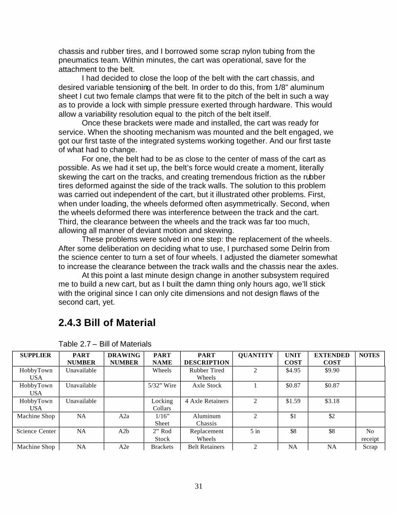
chassis and rubber tires, and I borrowed some scrap nylon tubing from the pneumatics team. Within minutes, the cart was operational, save for the attachment to the belt. I had decided to close the loop of the belt with the cart chassis, and desired variable tensioning of the belt. In order to do this, from 1/8” aluminum sheet I cut two female clamps that were fit to the pitch of the belt in such a way as to provide a lock with simple pressure exerted through hardware. This would allow a variability resolution equal to the pitch of the belt itself. Once these brackets were made and installed, the cart was ready for service. When the shooting mechanism was mounted and the belt engaged, we got our first taste of the integrated systems working together. And our first taste of what had to change. For one, the belt had to be as close to the center of mass of the cart as possible. As we had it set up, the belt’s force would create a moment, literally skewing the cart on the tracks, and creating tremendous friction as the rubber tires deformed against the side of the track walls. The solution to this problem was carried out independent of the cart, but it illustrated other problems. First, when under loading, the wheels deformed often asymmetrically. Second, when the wheels deformed there was interference between the track and the cart. Third, the clearance between the wheels and the track was far too much, allowing all manner of deviant motion and skewing. These problems were solved in one step: the replacement of the wheels. After some deliberation on deciding what to use, I purchased some Delrin from the science center to turn a set of four wheels. I adjusted the diameter somewhat to increase the clearance between the track walls and the chassis near the axles. At this point a last minute design change in another subsystem required me to build a new cart, but as I built the damn thing only hours ago, we’ll stick with the original since I can only cite dimensions and not design flaws of the second cart, yet.
2.4.3 Bill of Material Table 2.7 – Bill of Materials
SUPPLIER PART NUMBER
DRAWING NUMBER
PART NAME
PART DESCRIPTION
QUANTITY UNIT COST
EXTENDED COST
NOTES
HobbyTown USA
Unavailable Wheels Rubber Tired Wheels
2 $4.95 $9.90
HobbyTown USA
Unavailable 5/32” Wire Axle Stock 1 $0.87 $0.87
HobbyTown USA
Unavailable Locking Collars
4 Axle Retainers 2 $1.59 $3.18
Machine Shop NA A2a 1/16” Sheet
Aluminum Chassis
2 $1 $2
Science Center NA A2b 2” Rod Stock
Replacement Wheels
5 in $8 $8 No receipt
Machine Shop NA A2e Brackets Belt Retainers 2 NA NA Scrap

32
2.4.4 Conclusion
My conclusion at present is simple. I have made all of the changes I have found to be necessary and have integrated them into the new cart. The flaws of the old cart are above, and the flaws of the new cart are unknown unknowns at this time. I will assert the critical importance of placing the applied force as close as possible to the centroid, in this application, it is key.

33

33
Chapter 3: Firing
3.1 Ball Firing Sub System Nathaniel Kurczewski
The ball firing system consists of the firing assembly, the manifold assembly, the ball feed assembly, and the serve and spin assemblies. The integration of these systems is shown in drawings B1 and B2. The entire system is mounted to the cart. The bottom of the base is screwed to the cart from the underside. All tubing is drawn out the back with enough slack for the entire system to be moved along the track without interferences. The electrical wires are routed in a similar fashion. The entire system is 39.4 inches high, 5.9 inches wide, and 18 inches long and weighs approximately 3 lbs. (excluding the manifold assembly and air compressor). 3.1 Firing Assembly (Nathaniel Kurczewski) 3.1.1 Introduction This system is responsible for the actual projection of the ping pong ball. It must fulfill multiple requirements for the course as well as for the team. The course requires that we be able to hit a one square foot section anywhere on the table, as well as being able to adjust for service and volleys . The group set requirements forth as follows: we did not want to duplicate the state of the art, we wanted a lightweight shooter, we wanted a shooter that fulfilled the course requirements, we wanted to accommodate both size balls, 38 and 40 mm, and we wanted a shooter that integrated easily with the augmented reality system. Our groups augmented reality robots ultimate goal was to create a more life-like table tennis robot. In doing so, the controls group was presented with an extensive and difficult task. It was thus decided to keep the shooter as simple as possible for the controls group to program for and work with. It was decided that the easiest, most efficient approach for our group would be to use compressed air to fire the ball. However, late in the construction, it was decided to also add a spinning wheel to give the ball more velocity. These changes will be discussed in further detail in the next section. 3.1.2 Design Evolution The shooter was initially designed to operate solely off of compressed air. An air compressor would supply the air at 90 psi. A burst of air would be fired (using a solenoid valve) which would propel the ball. The pressure would be manually adjustable to adjust the velocity of the ball. This idea was abandoned after early

34
tests resulted in numerous problems. First, there was a need to accommodate two sizes of balls, the 40mm and 38mm balls. The 40mm ball fits snugly inside the PVC pipe, whose inside diameter is 1.592 inches (40.437 mm). This would essentially create an air tight seal and the ball would be propelled with the pressure created by the air. However, the 38 mm ball is too small to create an air tight seal, so the ball would be projected by the actual stream of air. This creates inconsistencies between the two balls. This is not a problem if one type of ball is used exclusively, but if both balls are to be used interchangeably then this is more difficult to control. The second problem was that when using a burst of air to fire, some of the air would escape out of the ball feed opening in the top of the barrel. This problem was partially solved by using a solid plate which would slide over and cover this hole. However, this was still not an air tight seal. Once experimentation using the burst of air to fire the balls began, it was discovered that it would not in fact fire the 38mm ball at all. The air inlet was centered directly behind the ball. When a burst of air was fired, instead of firing the ball, it actually sucked it in. This occurred because the air hit the center of the ball and curved around the ball, causing it to actually stick to the air source (see
Figure 3.1). This was not the case with the 40mm ball. Several ideas were suggested to solve this problem, including offsetting the air stream, using more pressure, and not using a raw burst of air at all. To correct the problems, the latter method was chosen. Instead pneumatic pistons would be used to fire the ball. A dual acting pneumatic piston was mounted behind the ball and the piston arm was used to
strike the ball. The kinetic energy of the piston would be transferred to the ball and would provide the means for projection. This would alleviate all of the earlier problems. Both ball sizes could now be accommodated. There was no longer a problem of air escaping. Also, an added benefit was that air consumption was drastically reduced. The piston for firing is split off of a line which also supplies the ball feed piston. The ball feed piston works simultaneously with the firing piston off of the same solenoid valve. The velocity was to be adjusted using the two inlet/outlet valves on the piston. This would adjust the amount of air entering the cylinder. The optimal ball velocity at the point of impact was determined to be about 160 feet per second. However, this neglects the following: The coefficient of restitution between the ball and piston when struck, friction between the ball and the barrel, drag on the ball while moving, the work needed to push the column of air out of the end of the barrel as the ball exits, minor and major flow losses in the air system due to head loss, bends, valves, edges, etc., frictional losses in the piston, air exiting the solenoid valve at the outlet, and air pressure being used by the ball feed piston. These losses all affect the pressure of the air
Figure 3.1
35
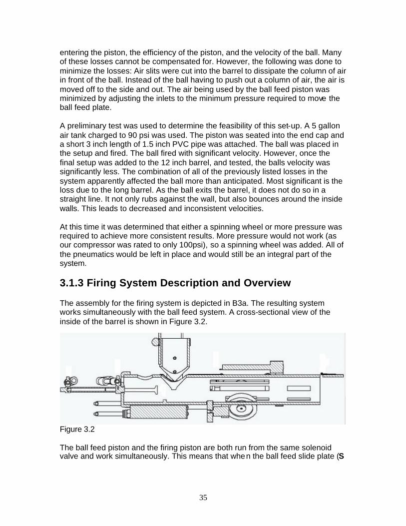
entering the piston, the efficiency of the piston, and the velocity of the ball. Many of these losses cannot be compensated for. However, the following was done to minimize the losses: Air slits were cut into the barrel to dissipate the column of air in front of the ball. Instead of the ball having to push out a column of air, the air is moved off to the side and out. The air being used by the ball feed piston was minimized by adjusting the inlets to the minimum pressure required to move the ball feed plate. A preliminary test was used to determine the feasibility of this set-up. A 5 gallon air tank charged to 90 psi was used. The piston was seated into the end cap and a short 3 inch length of 1.5 inch PVC pipe was attached. The ball was placed in the setup and fired. The ball fired with significant velocity. However, once the final setup was added to the 12 inch barrel, and tested, the balls velocity was significantly less. The combination of all of the previously listed losses in the system apparently affected the ball more than anticipated. Most significant is the loss due to the long barrel. As the ball exits the barrel, it does not do so in a straight line. It not only rubs against the wall, but also bounces around the inside walls. This leads to decreased and inconsistent velocities. At this time it was determined that either a spinning wheel or more pressure was required to achieve more consistent results. More pressure would not work (as our compressor was rated to only 100psi), so a spinning wheel was added. All of the pneumatics would be left in place and would still be an integral part of the system. 3.1.3 Firing System Description and Overview The assembly for the firing system is depicted in B3a. The resulting system works simultaneously with the ball feed system. A cross-sectional view of the inside of the barrel is shown in Figure 3.2.
Figure 3.2 The ball feed piston and the firing piston are both run from the same solenoid valve and work simultaneously. This means that when the ball feed slide plate (S

36
in Figure 3.3) retracts, allowing a ball (B in Figure 3.3) to enter the barrel, the firing piston (P in Figure 3.3) retracts as well, making room for the ball, figure 3.4.
Figure 3.3
Figure 3.4 Then, the piston fires the ball forward, figure 3.5, into the already spinning wheel (W in figure 3.3) as the ball feed slide plate is simultaneously retracted to prevent more balls from entering the barrel.
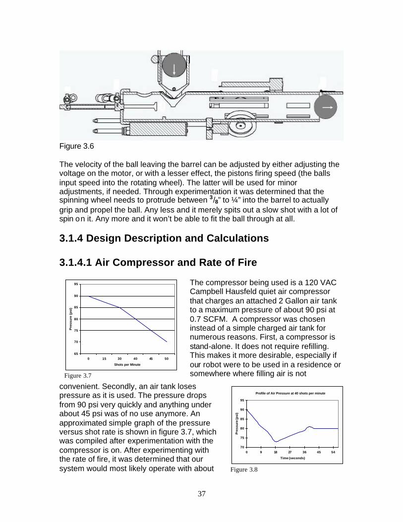
Figure 3.5 This process repeats itself in rapid succession, shown in figure 3.6
37
Figure 3.6 The velocity of the ball leaving the barrel can be adjusted by either adjusting the voltage on the motor, or with a lesser effect, the pistons firing speed (the balls input speed into the rotating wheel). The latter will be used for minor adjustments, if needed. Through experimentation it was determined that the spinning wheel needs to protrude between 3/8” to ¼” into the barrel to actually grip and propel the ball. Any less and it merely spits out a slow shot with a lot of spin on it. Any more and it won’t be able to fit the ball through at all. 3.1.4 Design Description and Calculations 3.1.4.1 Air Compressor and Rate of Fire
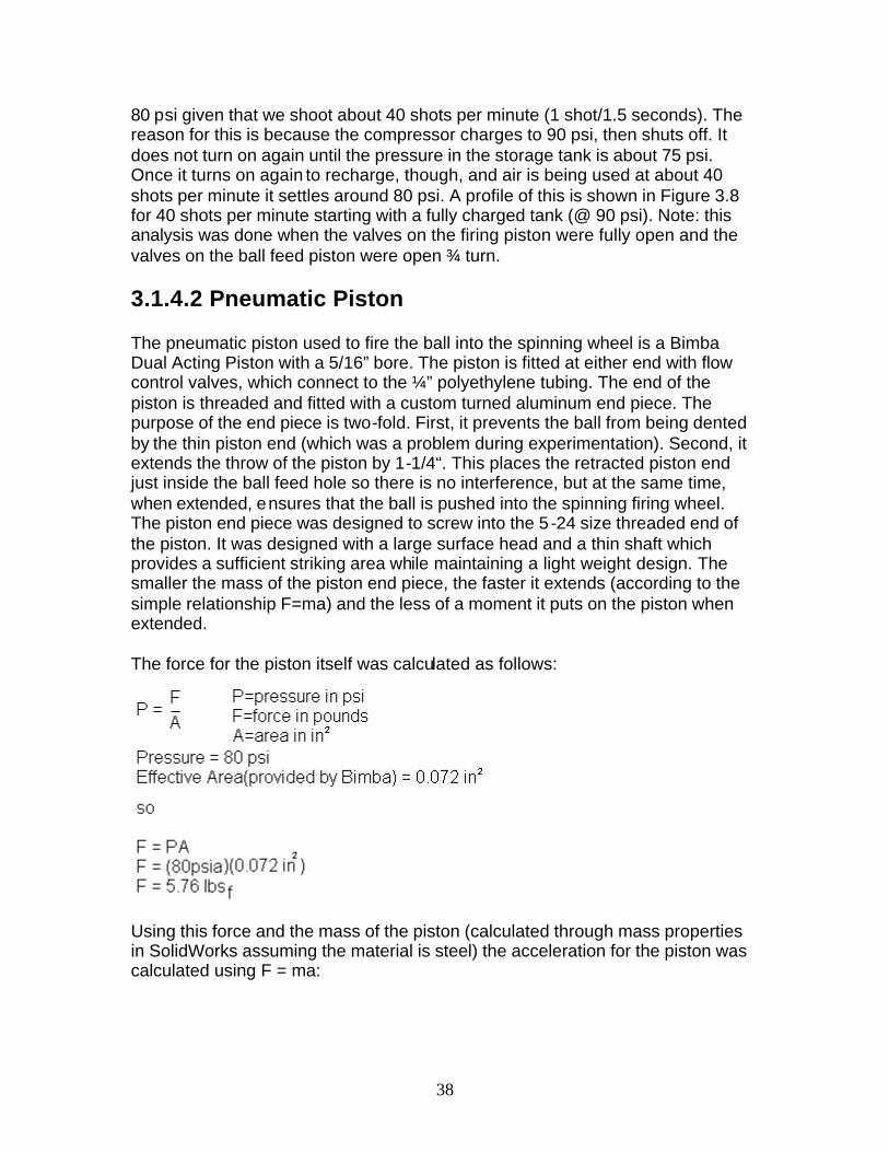
The compressor being used is a 120 VAC Campbell Hausfeld quiet air compressor that charges an attached 2 Gallon air tank to a maximum pressure of about 90 psi at 0.7 SCFM. A compressor was chosen instead of a simple charged air tank for numerous reasons. First, a compressor is stand-alone. It does not require refilling. This makes it more desirable, especially if our robot were to be used in a residence or somewhere where filling air is not
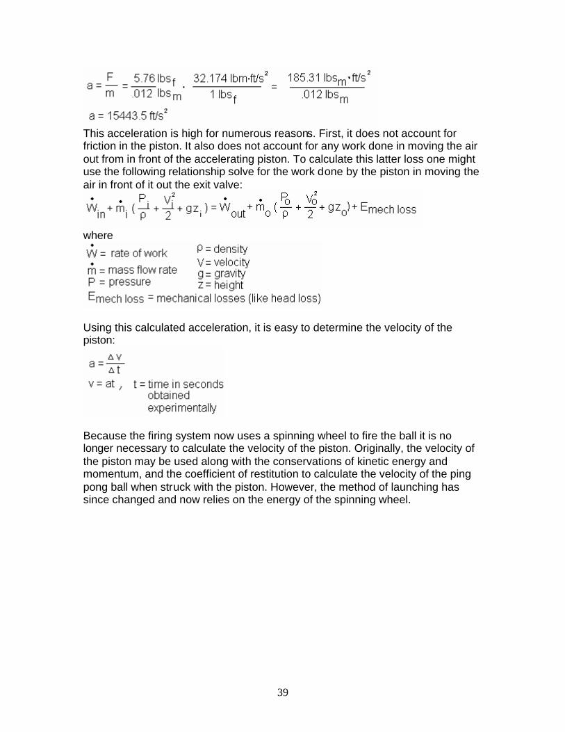
convenient. Secondly, an air tank loses pressure as it is used. The pressure drops from 90 psi very quickly and anything under about 45 psi was of no use anymore. An approximated simple graph of the pressure versus shot rate is shown in figure 3.7, which was compiled after experimentation with the compressor is on. After experimenting with the rate of fire, it was determined that our system would most likely operate with about
65
70
75
80
85
90
95
0 15 30 40 45 50
Shots per Minute
Pre
ssu
re (
psi
)
Figure 3.7
Profile of Air Pressure at 40 shots per minute
70
75
80
85
90
95
0 9 18 27 36 45 54
Time (seconds)
Pre
ssu
re (p
si)
Figure 3.8
38
80 psi given that we shoot about 40 shots per minute (1 shot/1.5 seconds). The reason for this is because the compressor charges to 90 psi, then shuts off. It does not turn on again until the pressure in the storage tank is about 75 psi. Once it turns on again to recharge, though, and air is being used at about 40 shots per minute it settles around 80 psi. A profile of this is shown in Figure 3.8 for 40 shots per minute starting with a fully charged tank (@ 90 psi). Note: this analysis was done when the valves on the firing piston were fully open and the valves on the ball feed piston were open ¾ turn. 3.1.4.2 Pneumatic Piston The pneumatic piston used to fire the ball into the spinning wheel is a Bimba Dual Acting Piston with a 5/16” bore. The piston is fitted at either end with flow control valves, which connect to the ¼” polyethylene tubing. The end of the piston is threaded and fitted with a custom turned aluminum end piece. The purpose of the end piece is two-fold. First, it prevents the ball from being dented by the thin piston end (which was a problem during experimentation). Second, it extends the throw of the piston by 1-1/4“. This places the retracted piston end just inside the ball feed hole so there is no interference, but at the same time, when extended, ensures that the ball is pushed into the spinning firing wheel. The piston end piece was designed to screw into the 5 -24 size threaded end of the piston. It was designed with a large surface head and a thin shaft which provides a sufficient striking area while maintaining a light weight design. The smaller the mass of the piston end piece, the faster it extends (according to the simple relationship F=ma) and the less of a moment it puts on the piston when extended. The force for the piston itself was calculated as follows:
Using this force and the mass of the piston (calculated through mass properties in SolidWorks assuming the material is steel) the acceleration for the piston was calculated using F = ma:
39
This acceleration is high for numerous reasons. First, it does not account for friction in the piston. It also does not account for any work done in moving the air out from in front of the accelerating piston. To calculate this latter loss one might use the following relationship solve for the work done by the piston in moving the air in front of it out the exit valve:
where
Using this calculated acceleration, it is easy to determine the velocity of the piston:
Because the firing system now uses a spinning wheel to fire the ball it is no longer necessary to calculate the velocity of the piston. Originally, the velocity of the piston may be used along with the conservations of kinetic energy and momentum, and the coefficient of restitution to calculate the velocity of the ping pong ball when struck with the piston. However, the method of launching has since changed and now relies on the energy of the spinning wheel.
40
3.1.4.3 Firing Wheel Assembly
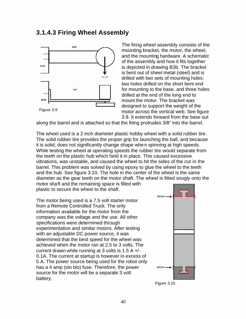
The firing wheel assembly consists of the mounting bracket, the motor, the wheel, and the mounting hardware. A schematic of the assembly and how it fits together is depicted in drawing B3b. The bracket is bent out of sheet metal (steel) and is drilled with two sets of mounting holes: two holes drilled on the short bent end for mounting to the base, and three holes drilled at the end of the long end to mount the motor. The bracket was designed to support the weight of the motor across the vertical web. See figure 3.9. It extends forward from the base out
along the barrel and is attached so that the firing protrudes 3/8” into the barrel. The wheel used is a 2 inch diameter plastic hobby wheel with a solid rubber tire. The solid rubber tire provides the proper grip for launching the ball, and because it is solid, does not significantly change shape when spinning at high speeds. While testing the wheel at operating speeds the rubber tire would separate from the teeth on the plastic hub which held it in place. This caused excessive vibrations, was unstable, and caused the wheel to hit the sides of the cut in the barrel. This problem was solved by using epoxy to glue the wheel to the teeth and the hub. See figure 3.10. The hole in the center of the wheel is the same diameter as the gear teeth on the motor shaft. The wheel is fitted snugly onto the motor shaft and the remaining space is filled with plastic to secure the wheel to the shaft. The motor being used is a 7.5 volt starter motor from a Remote Controlled Truck. The only information available for the motor from the company was the voltage and the use. All other specifications were determined through experimentation and similar motors. After testing with an adjustable DC power source, it was determined that the best speed for the wheel was achieved when the motor ran at 2.5 to 3 volts. The current drawn while running at 3 volts is 1.5 A +/- 0.1A. The current at startup is however in excess of 5 A. The power source being used for the robot only has a 4 amp (slo blo) fuse. Therefore, the power source for the motor will be a separate 3 volt battery.
Figure 3.9
Figure 3.10
41
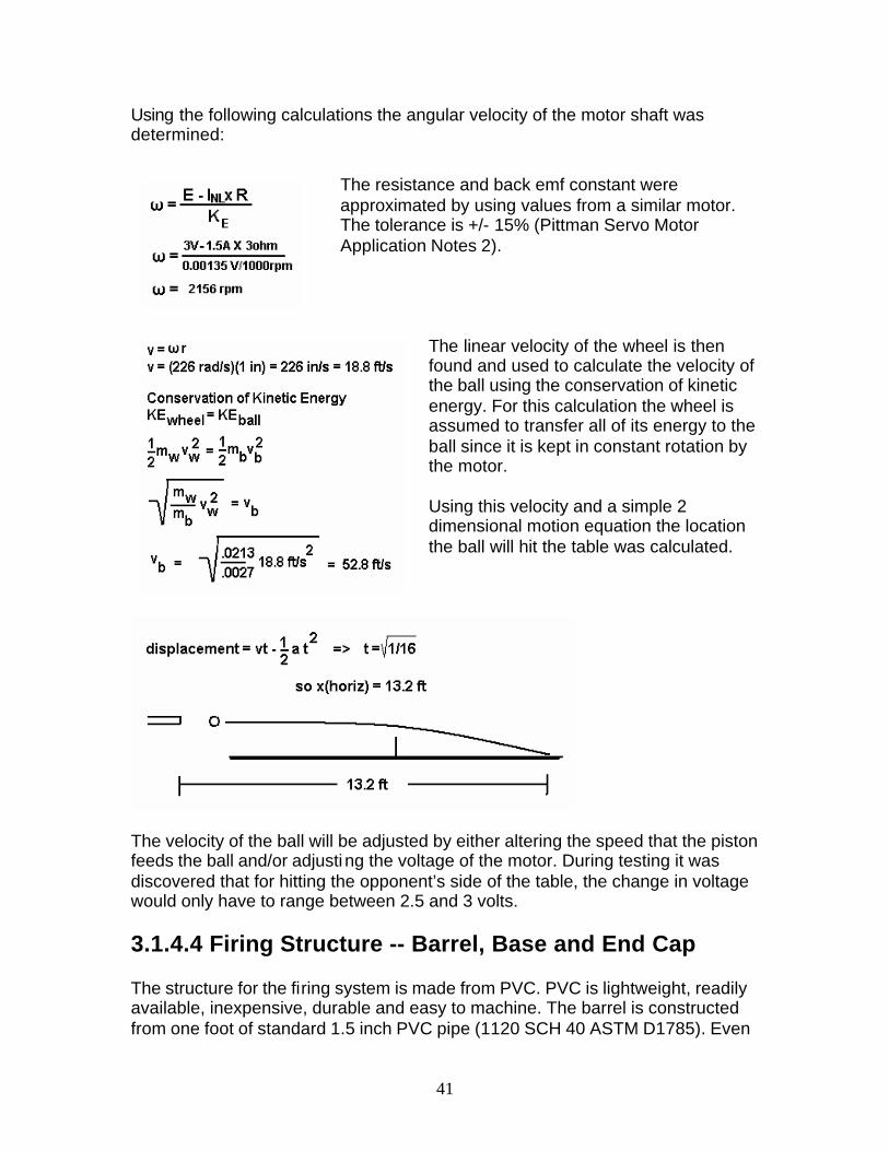
Using the following calculations the angular velocity of the motor shaft was determined:
The resistance and back emf constant were approximated by using values from a similar motor. The tolerance is +/- 15% (Pittman Servo Motor Application Notes 2).
The linear velocity of the wheel is then found and used to calculate the velocity of the ball using the conservation of kinetic energy. For this calculation the wheel is assumed to transfer all of its energy to the ball since it is kept in constant rotation by the motor. Using this velocity and a simple 2 dimensional motion equation the location the ball will hit the table was calculated.
The velocity of the ball will be adjusted by either altering the speed that the piston feeds the ball and/or adjusting the voltage of the motor. During testing it was discovered that for hitting the opponent’s side of the table, the change in voltage would only have to range between 2.5 and 3 volts. 3.1.4.4 Firing Structure -- Barrel, Base and End Cap The structure for the firing system is made from PVC. PVC is lightweight, readily available, inexpensive, durable and easy to machine. The barrel is constructed from one foot of standard 1.5 inch PVC pipe (1120 SCH 40 ASTM D1785). Even

42
though it is labeled 1.5 inches, the actual outside diameter is 1.90 inches and the actual inside diameter is 1.57 inches. Incidentally this is almost a perfect fit for ping pong balls: the 40 mm is 1.56 inches in diameter and the 38 mm is 1.48 inches in diameter. The barrels ball inlet hole is cut to fit the 40 mm ball, and has a dimple and back stop piece immediately underneath to prevent the ball from rolling back into the barrel or out the front. See figure 3.12. In order to lighten the barrel and increase air flow in front of and behind the firing ball, a hole in the rear (see figure 3.12) and several slits were added at the end of the barrel; see drawings B3ci and B3cii. The barrel is then fitted with a 1.5” PVC end cap. There is a hole in the center rear of the end cap for the piston. This hole has a 1/8” pipe thread for the piston to screw into. There are also 4 holes symmetrically placed around the center of the end cap to reduce weight and provide more paths for airflow for when the ball is being fired. The end cap’s length was also shortened to reduce weight and save space. Reference drawing B3d. The base is also machined out of PVC and has several functions. It provides for a secure barrel mount, a secure firing motor bracket mount, and a place to mount the solenoid valves. It also mounts the entire firing system to the aluminum cart with two machine screws. The base is a solid piece of PVC to provide the most strength for all of the mounting screws. 3.1.5 Conclusion The final firing system uses a hybrid spinning wheel/pneumatic piston launching method with speed varying ability. The air is supplied with a quiet compressor and the voltage for the motor with a 3 volt battery. The system integrates easily with the ball feed mechanism, the serve and spin mechanism, the mobility system and the controls/augmented reality system. In hindsight, if I were to redesign this system I would go with spinning wheels from the beginning. I would leave it up to the controls guys to then dictate whether or not they want to adjust the wheel speeds independently for different speeds and spins. Spinning wheels are the most efficient means for projecting the ball, which is why the Newgy and TT-matic robots use them. I would still
Figure 3.11

43
incorporate pneumatics. Pneumatics are very efficient and easy to work with, and make our shooter unique. 3.1.6 Chapter Nomenclature A: amp ASTM: American Society for Testing and Materials KE: kinetic energy lbf: pound force lbm: pound mass m: mass mm: millimeters (in reference to the standard size of the ping pong balls psi: pounds per square inch PVC: Polyvinyl Chloride v: velocity V: volt 3.1.7 Bill of Materials Table 3.1- Bill of Materials
FIRING SUB-ASSEMBLY BILL OF MATERIALS
SUPPLIER PART NO. DRWG.
NO. PART NAME PART DESCRIPTION QTY. UNIT COST EXTENDED
COST
BORROWED (ALSO AVAILABLE AT
GRAINGER) 45A-RR1-
DACA-1BA SOLENOID VALVE
MAC VALVES BRAND 45 SERIES, 1/8" NPT PORT
SIZE 1 $31.00 BD CAMPBELL HAUSFELD
(BOUGHT OFF EBAY) FP2003
AIR COMPRESSOR
120 V COMPRESSOR AND 2 GAL. STORAGE TANK,
0.7 SCFM @ 90 PSI 1 $94.99 $94.99
SHAKOS PT24044NA-
1000 POLYETHYLENE
TUBING 1/4" TUBING (.040 WALL) 45
FT. $0.19 $8.55
B4b MANIFOLD
1-1/2" ALUMINUM BAR STOCK, 1 INLET WITH 1/4" PIPE THREAD, 3 OUTLETS WITH 1/8" PIPE THREAD
0.75 LBS. 4/LB. $3.00
BORROWED (ALSO AVAILABLE AT
GRAINGER) 0072-DXP
#MJ PNEUMATIC
PISTONS BIMBA DUAL ACTING PISTON, 5/16" BORE 1 $18.00 BD
SHAKOS 1168X4
PUSH TO CONNECT FITTINGS
1/4" MALE NPT/TUBE PUSH TO CONNECT 3 $2.61 $7.83
BORROWED (ALSO AVAILABLE AT
GRAINGER) 6MN01
PUSH TO CONNECT
ELBOW SWIVEL FITTINGS
ANDERSON, 1/4" TUBE SIZE, 1/8" THREAD SIZE 2 $3.57 BD
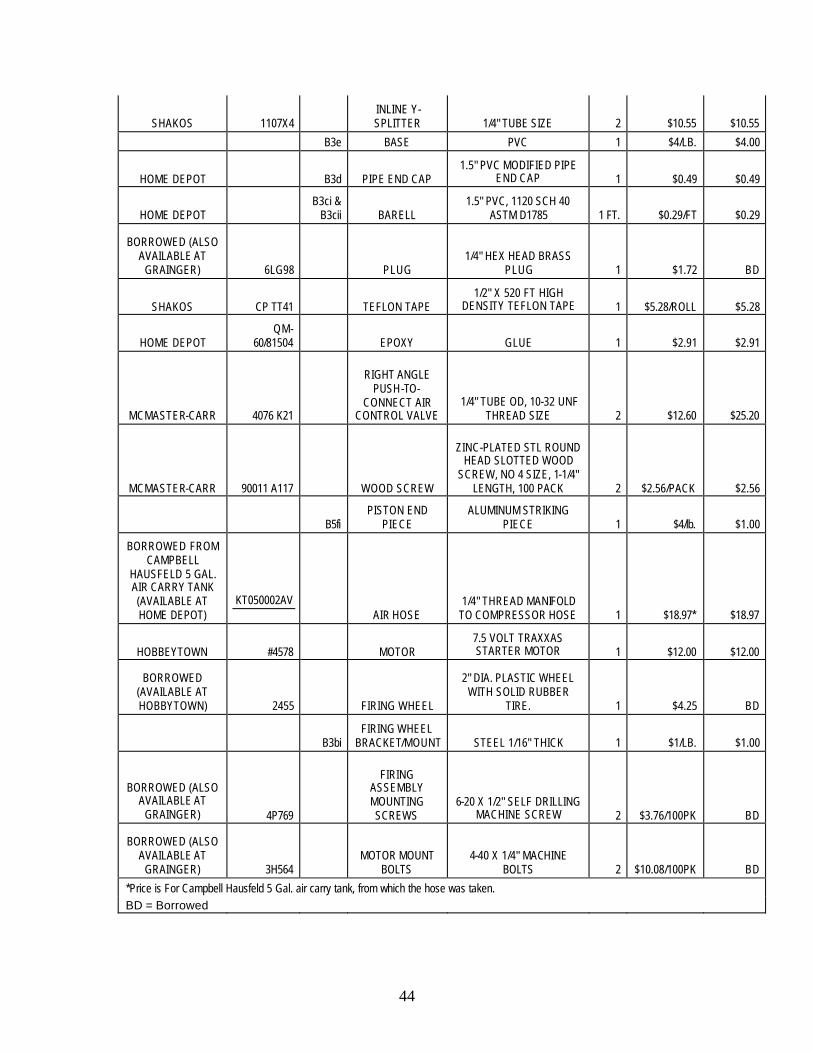
44
SHAKOS 1107X4 INLINE Y- SPLITTER 1/4" TUBE SIZE 2 $10.55 $10.55
B3e BASE PVC 1 $4/LB. $4.00
HOME DEPOT B3d PIPE END CAP 1.5" PVC MODIFIED PIPE
END CAP 1 $0.49 $0.49
HOME DEPOT B3ci &
B3cii BARELL 1.5" PVC, 1120 SCH 40
ASTM D1785 1 FT. $0.29/FT $0.29
BORROWED (ALSO AVAILABLE AT
GRAINGER) 6LG98 PLUG 1/4" HEX HEAD BRASS
PLUG 1 $1.72 BD
SHAKOS CP TT41 TEFLON TAPE 1/2" X 520 FT HIGH
DENSITY TEFLON TAPE 1 $5.28/ROLL $5.28
HOME DEPOT QM-
60/81504 EPOXY GLUE 1 $2.91 $2.91
MCMASTER-CARR 4076 K21
RIGHT ANGLE PUSH-TO-
CONNECT AIR CONTROL VALVE
1/4" TUBE OD, 10-32 UNF THREAD SIZE 2 $12.60 $25.20
MCMASTER-CARR 90011 A117 WOOD SCREW
ZINC-PLATED STL ROUND HEAD SLOTTED WOOD
SCREW, NO 4 SIZE, 1-1/4" LENGTH, 100 PACK 2 $2.56/PACK $2.56
B5fi PISTON END
PIECE ALUMINUM STRIKING
PIECE 1 $4/lb. $1.00
BORROWED FROM CAMPBELL
HAUSFELD 5 GAL. AIR CARRY TANK (AVAILABLE AT HOME DEPOT)
KT050002AV AIR HOSE
1/4" THREAD MANIFOLD TO COMPRESSOR HOSE 1 $18.97* $18.97
HOBBEYTOWN #4578 MOTOR 7.5 VOLT TRAXXAS STARTER MOTOR 1 $12.00 $12.00
BORROWED (AVAILABLE AT HOBBYTOWN) 2455 FIRING WHEEL
2" DIA. PLASTIC WHEEL WITH SOLID RUBBER
TIRE. 1 $4.25 BD
B3bi FIRING WHEEL
BRACKET/MOUNT STEEL 1/16" THICK 1 $1/LB. $1.00
BORROWED (ALSO AVAILABLE AT
GRAINGER) 4P769
FIRING ASSEMBLY MOUNTING SCREWS
6-20 X 1/2" SELF DRILLING MACHINE SCREW 2 $3.76/100PK BD
BORROWED (ALSO AVAILABLE AT
GRAINGER) 3H564 MOTOR MOUNT
BOLTS 4-40 X 1/4" MACHINE
BOLTS 2 $10.08/100PK BD
*Price is For Campbell Hausfeld 5 Gal. air carry tank, from which the hose was taken. BD = Borrowed

45
3.1.8 References Pittman Servo Motor Application Notes. Pittman, Harleysville, PA. Available
online: http://www.pittmannet.com/pdf/220000ALL.pdf.

46
3.2 Ball Hopper Assembly Eric Jacob
Figure 3.12
3.2.1 Introduction In order for any automatic shooting device to work, a means of loading the object to be fired must first be assembled. There are several options for attaining a loading device which is for the most part based, on the mechanics of the shooting device. These devices range from, gravity fed hoppers, to spring loaded, to piston fed devices.
Based on the design of our shooting device, our loading system had several limitations. Since the device is using a piston in the rear of the barrel, a rear loading option was out of the question. This led to the availability of other access points to which the ball could be fed, such as through the front of the barrel, or through one of the sides. Loading the gun from the front required too much time, and mechanics. This option, would not allow, a high rate of feed, not to mention the probability of controlling the device so when the ball was and the timing to when the piston was fired varied too greatly. Loading from the top did require a time allotment, but it was a much more feasible task. Since we were using pneumatics to launch our system, it made more sense to bleed some of the pressure, to use a pneumatic loader instead of a motor. In order to maximize total usage of balls, we figured we had to use some feeder that kept compressing the balls into the shooting device, thus gravity fed made the best sense. It required less work on the mechanics side, and allowed balls to space themselves while and before being shot. Other possibilities were loading the gun from the bottom, with some sort of spring device or from the sides, but the know how was left in the idea for a gravity fed hopper. Compression was not needed, and neither was preciseness or where the ball was placed, which let this idea lead the way. .

47
3.2.2 The Hopper The ball hopper assembly’s main objective is to hold a capacity of 80 Ping-Pong balls, and feed them into the launching mechanism. The balls will be held in helix shaped plastic tubing, and gravity fed into the top of the shooting device. These calculations can be found at the end of the chapter. The total length of the helix will be 125.984 inches or 3200 mm. The helix will be at a 10.1degree incline, and have an inside diameter of 45mm, thus allowing it to easily handle the diameter of a ping pong ball drawing 2). Being attached to the top of the screen, the hopper will allow the balls to be easily fed. At the top of the tubing a plastic bucket will be placed, to allow the ability of more balls to be loaded at a given time. Flexibility is a must in the tubing. It must be able to bend easily and move with the cart without creating too much torque on either the cart, or the screen. The inside diameter and smoothness of the inside of the tubing also must be available to insure that the ping balls are able to freely move through the tubing with little resistance. This tubing will be connected to the top of a piece of PVC tubing that has been formatted to allow ping balls to move freely into the barrel. This was completed by end milling the end of the PVC to not allow any variation of the location of where the ball will be fed. At the top of the tubing an attachment can be made, to incorporate the use of more ping pong balls. This attachment would be a 1 foot squared container capable of holding an extra 512 balls maximum. Without a motor to help the flow of balls this idea, would have to be further researched to incorporate the complete 512 balls in 1ft^3 box like configuration. Ideas like a motor to control ball movement into the tubing would be a big advantage, as well, as modifying the interior to create a funnel, for which the balls would automatically fall into the hopper. Unfortunately, the tubing that was required was beyond the budget of the group, and could not be bought, so an alternative form of a hopper was needed. The idea of attaching 3 wires together extending from the hopper holder was created. These so called wire frames will encompass the ping pong balls, and freely be able to move with the cart, and shooter. At a length of only 3 feet the amount of balls that it is able to hand is much less then expected. This length will only be able to hold 25 balls instead of 80. As the cart moves back and forth this, hopper will be projected into the air and hold onto the balls.
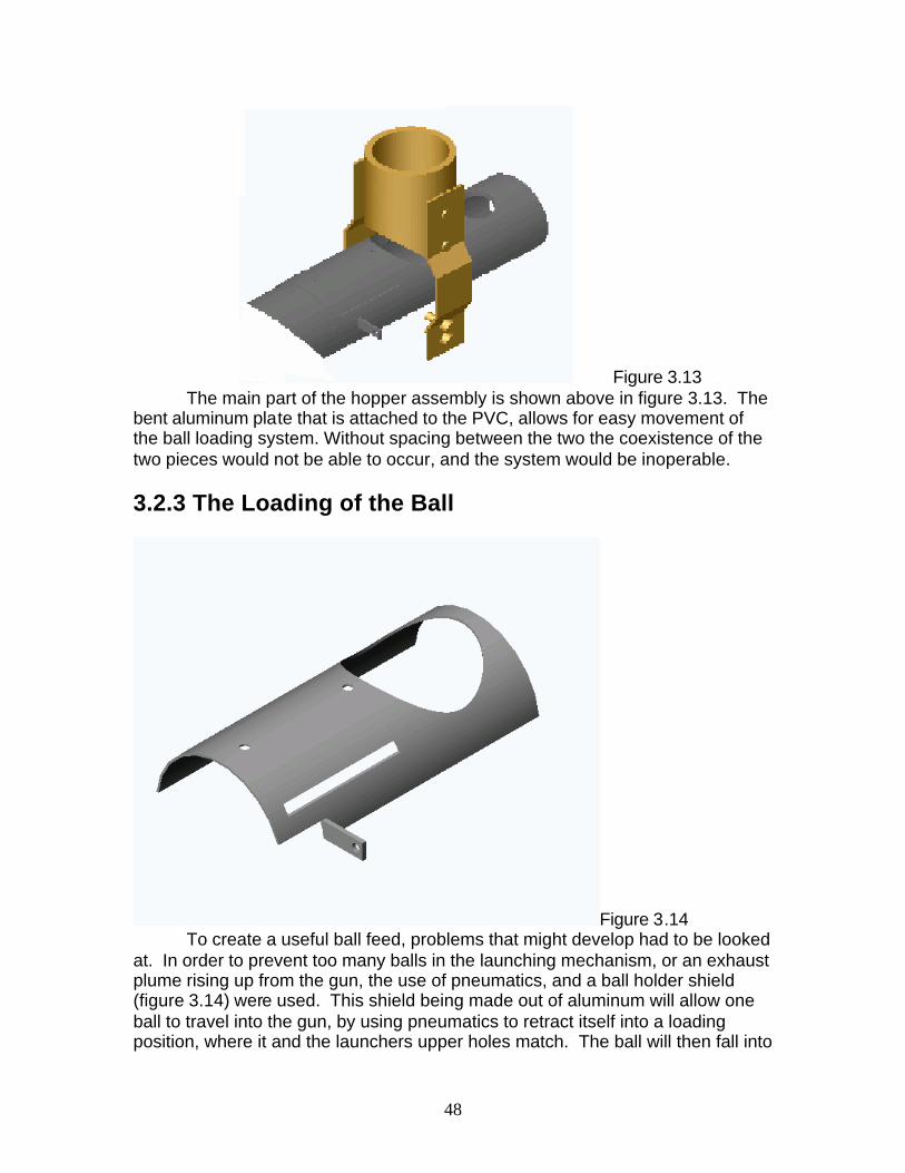
48
Figure 3.13 The main part of the hopper assembly is shown above in figure 3.13. The bent aluminum plate that is attached to the PVC, allows for easy movement of the ball loading system. Without spacing between the two the coexistence of the two pieces would not be able to occur, and the system would be inoperable. 3.2.3 The Loading of the Ball
Figure 3.14 To create a useful ball feed, problems that might develop had to be looked
at. In order to prevent too many balls in the launching mechanism, or an exhaust plume rising up from the gun, the use of pneumatics, and a ball holder shield (figure 3.14) were used. This shield being made out of aluminum will allow one ball to travel into the gun, by using pneumatics to retract itself into a loading position, where it and the launchers upper holes match. The ball will then fall into

49
position. Since the barrel is sized to allow only 1 ball, only one ball will be able to fall into position. The rest of the balls will then apply a force onto that ball, while the shield is still open. When the shield closes it will exert a force of 15.3272 lb-force, or 68psi (Calculations are included at the end of the chapter), to rise the balls back away from the shooter. Once the shield is fully extended it will cover up the whole, and thus allow the gun to fire. The relationship between the loading shield and the firing piston, are equal. As the piston retracts the shield closes allowing just one ball fall through. When it closes it pushes the rest of the balls up and out of the way not allowing any contact between the ball being fired and the rest f the balls. On average we can load approximate one ball a second. This device works fairly well, and has few and far complaints. Now and then balls may get stuck in-between the plate and the PVC barrel. The good news is that the Pressure created by the piston on the ping pong balls is great enough to force the balls up and out of the way. The other concern that must be noticed is that when the whole opens for the ball to drop, if the speed of the piston on the loading plate is too great, then the ball will not fall into the tube, and a blank shot may be fired. This error is fairly easy to fix, through several manipulations. First make sure the all the holes, the hopper holder, the hole on the PVC, and the hold on the shield all line up correctly. Next adjust the pressure, on piston at both ends until the ball can easily fall into place. After these adjustments are made a simple adjustment to make sure that the pressure is sufficient on the Piston to close must be made by adjusting the pressure of the piston through the valves. Due to inconsistency in the pressure of the pneumatic system, no accurate calculations on adjustments can be made so manual adjustments need to be verified at the beginning of every usage. To create the maximum force on the ball, and consistency of shots, the ball must be placed in a certain position every time. We located where the piston reaches its maximum length, and decided to place the ball here. This would allow the piston to accelerate to its maximum velocity before striking the ball. The loading system was then assembled around this point. To ensure that the ball once fed would not move from its location to add on features were added to the interior of the barrel. The first was a small divot located at the center point of where the piston extended too, to give the ball a place to rest until it was struck. The second feature was plate located underneath where the piston would extend over. This plate prevented the ball from sliding back to an undesirable position. To prevent the ball from moving forward the gun is just slanted backward to allow the ball to roll back to the desired position. The only concern that we had when we first built this was how can a loading device such as the PVC located on top of the barrel and the separating shield exist together without interfering with each other (Assembly 1). This problem was easily solved with two pieces of aluminum. These pieces would be connected to the base plate and to the PVC at the same time, and would not be in contact with any other system. This would allow the PVC to exist about the loading plate, and the loading plate to move freely without touching the loading hopper.
50
3.2.4 Hopper Calculations: Ball size and Specifications: Diameter = 40mm or 1.5748inches Weight = 2.7grams or 10.5 ounce s= .00595lb*m Volume = 4/3*Pi*r^3 =1675.52 mm^3 or .001676 m^3 =2.59704 in^3 Needs to handle 80 Balls (Calculations on following pages) For straight Tubing 40mm*80 = 3200mm or 3.2m 1.5748in*80 = 125.984inches or 10.4987feet Height specification of
22inches 528mm
Helix Specification Height – 20inches or 508mm Length 125.98inches or 3,1998mm Radius – 1.823inches or 46.3mm 1 rotation height 2inches or 50.8mm Inside Diameter 45mm Add on Bucket feature for the hopper Dimensions 1ft^3 On the base [(1ft*12in/1ft)/(1.5inc ball diameter)]^3=512 balls Actual hopper used for amount of balls 3ft*12inches/1.5747inches(diameter)+2balls in hopper holder=25 balls Weight of 80 balls On plate directly 2.1168N or 15.3272 lb-f
Correlates to 68psi

51
3.2.5 Bill of Materials Table 3.2 – Bill of Materials
PART NUMBER
DRAWING NUMBER
PART NAME PART DESCRIPTION
# UNITS
UNIT COST EXTENDED COST
NOTES:
45A-AA1-DFBJ-1KE
SOLENOID VALVE
MAC VALVES BRAND 45
SERIES, 1/8" NPT PORT
SIZE
1 $31.00 $31.00 BORROWED Shared by piston assembly.
PT24044NA-
1000 POLYETHYLENE
TUBING 1/4" TUBING (.040 WALL)
10 FT. $0.19 $1.90
0072-DXP #MJ
PNEUMATIC PISTONS
BIMBA DUAL ACTING
PISTON, 5/16" BORE
1 $18.00 $18.00 BORROWED
6MN01 PUSH TO CONNECT
ELBOW SWIVEL FITTINGS
ANDERSON, 1/4" TUBE SIZE, 1/8"
THREAD SIZE
2 $3.57 $7.14 BORROWED
B5d Hopper Holder 1/8” bent Aluminum
2 4/LB $1.00
B3e Shooter BASE PVC 1 $4/LB. $4.00 Shared by piston
assembly. B5e PVC Ball Hopper 1.5" PVC, 1120
SCH 40 ASTM D1785
1
B5g Piston bracket 1/8” aluminum bracket
1 $4/Lb $1.00
90011 A117 WOOD SCREW ZINC-PLATED STL ROUND
HEAD SLOTTED
WOOD SCREW, NO 4
SIZE, 1-1/4" LENGTH, 100
PACK
4 $2.56/PACK $2.56
3.2.6 Conclusion The completion of the hopper assembly has its ups and downs in meeting the original requirements, set at the beginning of this project. The pneumatic operating system, used is what I consider to be the best part. The pneumatic system is efficient and effective at the same time. It’s ability to load balls, one at a time for a piston to move in some shape or form, in either firing or loading

52
makes this system a success. The one down fall of this feature is the requirement of compressed air to control it. Due to the fact that compressors are not a common tool laying around, and just add bulk to the final feature, another way to create the pneumatic control my be fairly feasible. A motor perhaps can be created to perform the same features. The actual hopper itself is where I believe the most problems occurred. The actual tubing that was depicted to be used, was unfortunately to expensive for this teams budget, so other sources were experimented with. Things such as plastic vacuum tubing was tried, but created too much torque in the end on both the CMU cam and firing device supports. Three aluminum strips were then decided to be used, and project outward from the hopper assembly. This system, does not secure the ball effectively, though it allows for easy movement of the ball. The other problem that this makes is that the amount of balls originally idealized to be used (80), can not fit in this amount of space, which makes this system much less desirable. Ideally the system to be used is a form of air duct piping that is fairly flexible. This allows for easy movement, which lowers the torque created, while maintaining the inside diameter for easy movement of ping pong balls on the interior. Other options for this system could be more feasible, but with the idea of creating a mechanism based on a device that has not been seen before, prevented from further development of other devices. It is my current belief that to make this machine more feasible a re-loadable is needed. This would require the creation of a ball collector, which could be loaded at the bottom of the shower curtain that we have decided to use as our back drop screen. This catching device can be created using PVC, and netting or other device that has minimal friction allowing for easy rolling movement of a ping pong ball. A conveyor could then take the ball up to a bucket hopper that would be able to into tubing. This conveyor does not require much work, and can either use other ping pong balls, to push each-other up into the hopper; much like the NEWGY machines of today, act as a drill; and pull the ball up to the top, or in an escalator fashion; and pick up each individual ball at the bottom and bring it to the top. The hopper bucket would have a spinning motor on the inside to insure that balls fill into flexible tubing that feeds to loading device. This is just one of the options that could have been created instead of the device used. The only problem with these other devices is, the time involved, along with the financial side of it, made these options not feasible. The system that is being used currently is not only reliable but proven, and thus it accomplishes its goal.

53
3.3 Serving / Lobbing and Spin Assemblies James Alan Rollo 3.3.1 Serving / Lobbing Assembly
Figure 3.15
For our project to seem more realistic, the machine must be able to serve the ball, as well as have the ability to lob the ball. Serving the ball is when the ball is presented, struck with a paddle, and then the ball hits your own side of the table before cleanly going over the net, and hitting the opposing players proper side. Lobbing the ball is when the opposing player has fairly returned the ball to your side of the table and you are able to strike the ball, and return back over the net hitting the opposing players side of the table, without hitting your own side. There are many ways to do this. Such ways include, angling the barrel, angling the entire unit it-self, redirecting the ball, and many other methods. The problem with our project is that our barrel for the launching mechanism will be going through a projector screen. Since the screen needs to be stretched tight around the protruding barrel, we are unable to move the barrel vertically to angle the trajectory of the ball. Since angling the barrel it-self is not an option, the only other feasible alternative would be to redirect the ball. The simplest way to redirect a ball coming out of the barrel would be to have a device at the end of the barrel redirect the ball to a proper angle. A plastic plate is placed at the end of the barrel to redirect the ball. The plate is held in
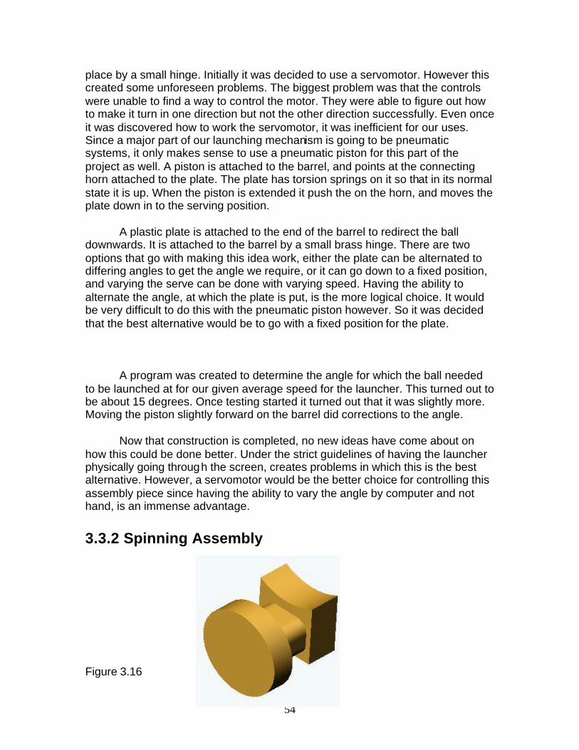
54
place by a small hinge. Initially it was decided to use a servomotor. However this created some unforeseen problems. The biggest problem was that the controls were unable to find a way to control the motor. They were able to figure out how to make it turn in one direction but not the other direction successfully. Even once it was discovered how to work the servomotor, it was inefficient for our uses. Since a major part of our launching mechanism is going to be pneumatic systems, it only makes sense to use a pneumatic piston for this part of the project as well. A piston is attached to the barrel, and points at the connecting horn attached to the plate. The plate has torsion springs on it so that in its normal state it is up. When the piston is extended it push the on the horn, and moves the plate down in to the serving position. A plastic plate is attached to the end of the barrel to redirect the ball downwards. It is attached to the barrel by a small brass hinge. There are two options that go with making this idea work, either the plate can be alternated to differing angles to get the angle we require, or it can go down to a fixed position, and varying the serve can be done with varying speed. Having the ability to alternate the angle, at which the plate is put, is the more logical choice. It would be very difficult to do this with the pneumatic piston however. So it was decided that the best alternative would be to go with a fixed position for the plate. A program was created to determine the angle for which the ball needed to be launched at for our given average speed for the launcher. This turned out to be about 15 degrees. Once testing started it turned out that it was slightly more. Moving the piston slightly forward on the barrel did corrections to the angle. Now that construction is completed, no new ideas have come about on how this could be done better. Under the strict guidelines of having the launcher physically going through the screen, creates problems in which this is the best alternative. However, a servomotor would be the better choice for controlling this assembly piece since having the ability to vary the angle by computer and not hand, is an immense advantage. 3.3.2 Spinning Assembly Figure 3.16

55
One of the main goals for this project to go above and beyond the current technologies that is currently out on the market. Every machine on the market currently, has the ability to put spin on the ball. So, it is imperative that our machine has the ability to put some kind of spin on the ball as well. There are many ways to put spin on the ball. Such ways are to use spinning wheels, puff of air on a certain area of the pad, or friction pads. For the current launcher that is made, the choice needs to be small and compact. It should also be easy to construct since it is a more minor part of the project. With these points in mind, the best choice would be to use a spinning wheel. To create a spinning wheel to put spin on the ball, would be small, light weight, easy to use, and easy to create. A small high-speed low voltage motor would be ideal for these purposes. The following motor is being used for this purpose:
Radio shack 1.5-2VDC Motor
Voltage Range: 1.5 – 3 volts
Current: 0.18 – 0.25 A @ no load
0.70 +- 15% @ max efficiency
Speed: 8700-RPM +- 12% @ no load
5800 RPM +- 12% @ max efficiency
Shaft length: 0.0787 mm
Output: 0.31 W
Torque: 5.3 g/cm
A special bracket needed to be made to attach this motor to the barrel, see the attached Solid Works files for the Motor Bracket. Once made it was attached to the barrel by plastic welding it on. In retrospect of creating the spinning wheel assembly, this choice is the best option for this purpose and wouldn’t change anything. Do to the fact that spin needs to be put on the ball, however in a manor that doesn’t add weight or take up unnecessary room, this is the best option. The motor works well and ideal for this because it is high speed but draws little current.
56
Chapter 4: Computer System Integration
4.1 Computer Programming Robert Van Dyk 4.1.1 Introduction
Constructing the code for the Table Tennis Robot served to integrate the three completely separate elements has not been an easy task. In summary, the computer program that runs the robot has to communicate with (1) the LabJack, (2) the CMUCam, and (3) the projector.
There were two options that could put together all these separate elements. LabView is encouraged to be used by the IED professors, though after assessing the Table Tennis Robot project there was a doubt about whether or not LabView would introduce a bottleneck that would slow down the overall execution time of the mechanical devices and computer I/O that the robot processes. Also, after many hours of going through the LabView program, no solution for how to communicate with the projector was found.
The second option is more of a computer science solution then engineering, though it was picked because it is more flexible then LabView. This option was to write the Table Tennis Robot program in Java. One huge advantage that Java has over LabView is that it makes use of pre-written software packages designed for each device we were using. To put it frankly, without the work of Chris Reigrut on the LabJack, the developers at Carnegie Mellon University on the CMUCam, or the resources for Java graphical support available on the Internet, the Nothing But Balls Table Tennis Robot would not have been possible. 4.1.2 The Projector/Video Files Because of the completely software driven nature of the projector, the code for this was derived first. I had several options to choose from while putting this program together and the following is the logical progression on how I eventually arrived at my decision.
At the onset of the project we were disillusioned into thinking that we would be able to use Macromedia Director, a powerful graphical program that we had false hope could be controlled via system calls from LabView. During our testing with Director though we learned several important things. First, we learned that there is no way to load every video clip we need into memory. Without going into too much detail, this is because each video clip we had is stored on the hard drive (30 Gigabytes) and in order to play it we must transfer it into computer memory (200 Megabutes). The time it takes to transfer from the hard drive to memory is not negligible. The result is that when we were playing
57
video clips in Director, it would noticeably pause for a fraction of a second while it was loading video. To alleviate this problem, we told Director to convert each video clip into a string of images and play that. With the super powerful graphics program, this resulted in a smooth flowing animation of Gus playing table tennis.
When we shifted from Director to Java, the “string of images” idea was preserved. While scouring the Internet for a method to control images in Java, I came across the Java Almanac web resource. There, I found a program called AnimApp.java that taught me how to display a string of images with Java. I was able to create and execute a video of Gus swaying back and forth in his “ready-mode” that ran flawlessly. Problems accorded when I trying to add a clip of Gus serving the ball. Java produced “Memory Overflow Exceptions”. What was happening in the Java program is the same as what happened in the Director program, only instead of a tiny stall – the error in Java stopped the program from continuing correctly. To alleviate this I changed the Java program to load an image dynamically before displaying it. With this, an unacceptable frame rate was produced. Though, the main problem with this approach is that it took huge magnitudes more time to play the short clips. The answer was fairly easy to come by, instead of playing all 140 or so images, skip every 4-9 images so that we can simulate Gus moving at a realistic pace. Using the experimental knowledge I had acquired during this process, I settled on the final version of the program that would load the entire “ready-mode” clip into memory, then dynamically load the shots of Gus hitting the ball.
It isn’t perfect, but is good enough for our prototype. If we were given more time, we would be able to simulate the powerful nature of the Director program with the simplicity of the Java program using a multi-threading technique – though with the tight IED time restriction there was not enough time for this. 4.1.3 The LabJack
How is it possible to control the LabJack from the laptop? This was a very important question that I needed to address before LabJack controlled devices were built, so that the group would know that I am in control. We first considered using LabView to control LabJack, though support for this was very weak on the LabJack website. As a historical note, our subgroup was able to successfully detect the “vibration” of the the Radio Shack Vibration Detect that we bought. (Unfortunately table tennis balls do not cause a great enough table vibration for these devices to be used in our project, so that part of our project flopped). Around that time I had knowledge of the CMUCam java program, and then I discovered the LabJackJava program written by Chris Reigrut of Teravation (http://www.teravation.com). This was the discovery that made Java the choice for how to run the software for the Nothing But Balls Table Tennis Robot.
Figuring out exactly how to use LabJackJava is a story on its own, though because of the LabJack Java Forum and help from Mr. Reigrut, I was able to get this working, and remove a huge burden from my shoulders. Correspondence between Mr. Reigut and myself is reproduced in ***********Appendix B************.

58
With knowledge I gained through the developer of LabJackJava, we became able to control motors and the solenoids that work with the ball shooter.
4.1.4 The CMUCam The CMUCam comes with an extensive Java test program available on the Carnegie Mellon website (www.cmu.edu). If you would like to download the code for yourself it is at http://www-2.cs.cmu.edu/~cmucam/Downloads/camGUI_1_1b.zip. I considered printing it out for this report, but after considering its sheer mass (it would have been over 20 pages with a tiny font) decided that it was best not to.
Keith worked hard to learn the essential commands that we would need to use the “Track Color” function, which we will be using to detect the position of the ball over time. Unfortunately that was a small task compared the task I had to do to get CMUcam working with our project. The CMUCam Java program is rather large in size. Overall, there are fourteen separate classes defined in the following fourteen files. The first six files were the most important to teach us how to control the CMUCam. The “serial” files were pretty much used in their entirety with the code in the final program. The function that describes “Track Color” is in CameraImage.java, so I used a good part of that file as well in the final. The other eight files define aspects of the test program that we didn’t need to work with. 4.1.5 Conclusion
The programming for the Nothing But Balls Table Tennis Robot was far from a simple task to complete. I would like to take all the credit, though this project marks the first time I have ever written a computer program of this magnitude and I would be lying if I said I could have done it myself. I would have never been able to figure out how to communicate through the USB port with the LabJack, so I would like to personally thank Chris Reigut for his work on the LabJackJava and his willingness to answer the many questions I posed for him. I also wouldn’t have been able to figure out how to communicate through the COM1 with the CMUCam. I would also like to thank Carnegie Mellon for having the ever helpful test program posted online.
1. CMUcamGUI.java 2. mainWindow.java 3. CameraImage.java 4. colorTrack.java 5. serialComm.java 6. serialPort.java 7. aboutWindow.java 8. camSettings.java 9. channelWindow.java 10. commWindow.java 11. meanWindow.java 12. outWindow.java 13. rawWindow.java 14. setWindow.java
Figure 4.1 – CMUcamGUI files

59
Although in addition to the guidance I received, integrating everything and making sure that the timing for everything works properly was a major task. In the end, there was no way to make everything function smoothly together. I guess the only other thing to do is present the code in Appendix C. Good luck with it.

60
4.2 Electronics Integration Liam Tallon 4.2.1 Introduction This chapter shows how a laptop is going to interface with the electronics that control the Ping-Pong robot. A laptop must have an intermediary circuit in order to control motors and solenoids. The goal was to make a circuit that consumes a minimum amount of power, from both the laptop and from the DC power supply. The circuit also needs to be 100 percent reliable and allow full use of the hardware connected. 4.2.2 Development In order to develop the circuit I had to meet some requirements set by the other subgroups that had elements interfacing with the circuit. I also had to operate within the parameters dictated by the hardware specification limitations. The needs of the other people our group were needed before I could finalize the design of the circuit. 4.2.2.1 Wire Requirements
The Wiring Schematic (Figure 4.3) shows all wire connections needed to
fulfill the robot control circuit. The Graphical representation of this circuit is shown in Figure 4.2. The correct gauges of wire must me chosen with regard to how much current the line is carrying. The maximum amperage carried on any one wire is 1.5 Amps, this occurs in the wires going to the track motor. Wire gauge #22 is capable of carrying 7 amps when wired in air. Wire gauge #22 is also the size that fits best in a protoboard, which makes it the ideal size wire to use for all components.
Protoboard Layout Diagram (Figure 4.2) is for placement of wires. All RED wires indicate a connection to a voltage source. All BLACK wires indicate a connection to a ground. All OTHER wires indicate connections between components in the circuit. Five colors are needed in the diagram in order for no wires to cross over a wire of the same color.
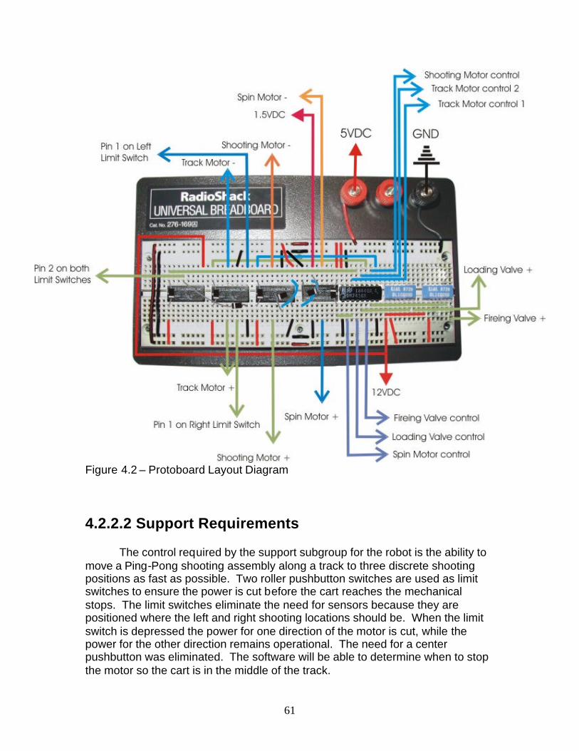
61
Figure 4.2 – Protoboard Layout Diagram 4.2.2.2 Support Requirements The control required by the support subgroup for the robot is the ability to move a Ping-Pong shooting assembly along a track to three discrete shooting positions as fast as possible. Two roller pushbutton switches are used as limit switches to ensure the power is cut before the cart reaches the mechanical stops. The limit switches eliminate the need for sensors because they are positioned where the left and right shooting locations should be. When the limit switch is depressed the power for one direction of the motor is cut, while the power for the other direction remains operational. The need for a center pushbutton was eliminated. The software will be able to determine when to stop the motor so the cart is in the middle of the track.
62
4.2.2.3 Shooting Requirements The shooting subgroup required the ability to operate a firing piston, firing
motor, deflecting piston, and a spin motor. Since the shooting subgroup decided to use a spinning wheel to fire the ball very late in the design process, I was not able to design a circuit for the laptop to modulate the speed of the firing motor. I decided to use a potentiometer to vary the voltage to the firing motor because it was the only way to do it in the limited time before the exposition. The LabJack we are using to interface the laptop with the motors and solenoids is capable of digital I/O as well as analog I/O. Relays turn on and off all motors and solenoids, switching direction of motors is also controlled by relays. All of the controls are operated by a digital high or digital low, which makes the programming and circuitry very simple and reliable.
4.2.2.4 Choosing Relays and Buffer I chose the 74F365 buffer because it has a high sinking current relative to its device type.
I chose relays with very small power requirements because the Buffer can sink a maximum of 64mA from each relay. The current being used by the relays must be less than the buffer can sink, so the LabJack doesn’t get an amount of current too large at its inputs. If the LabJack were to get a large current at one of its inputs, it could be damaged, or the laptop could be damaged. DPDT relays were chosen to control the reversing of the direction of the motors. The spin motor and Shooting motor both operate continuously when the power supply is on so they only require 1 DPDT relay each. The track motor is the only one that requires coming to a stop, so an additional SPDT relay is required. I could not find an SPDT relay that operated at 5VDC and had 2 Amp contact points, so a second DPDT relay was used. The Schematic (fig. 4.3) shows how the reversing of current is accomplished using one DPDT relay. Diode protection was needed to protect circuit elements from the spike in voltage generated by the coil in the relay. A spike in voltage could damage the buffer chip or the Laptop. SPDT relays with built in diode protection control the MAC valves. The MAC valves only need to be turned on and off. Using one SPDT relay for each MAC valve is a simple and energy efficient way of controlling them.

63
64
Figure 4.3 – Engineering Schematic of the Circuit 4.2.3 Experiments
All of the components needed to be tested prior to their inclusion in the complete system. I had to make sure the power sources could handle the current and voltage needed by the devices they operated. It is my job to make sure the circuits and all components included in them are operational before anything is hardwired to the laptop and LabJack. If a circuit is not operational it could damage the laptop or LabJack that it is connected to. It is also more difficult for the person doing the programming to determine if their program works when the hardware that it operates is not operational.
4.2.3.1 45A-RR1-DACA-1BA MAC Valve for operating parameters
The valve was borrowed, so I do not have a spec sheet for it. The printed
information on the valve is 24VAC, 7.4 watts. The valve was connected directly to a power supply in order to observe the voltage and current requirements of the device. At 24VDC the valve drew 0.72 Amps, using Power = Voltage * Current the valve requires 17.3 Watts of power. After testing the valve at the 24VDC voltage, I tested the minimum voltage needed to consistently operate the valve. The valve reliably switches at 10VDC drawing 0.36 Amps. The valve has the holding power to remain open down to 0.7VDC drawing 0.02 Amps.
4.2.3.1.1 Observations and Conclusions
The valve turning on and off was observed by a click noise that it made. At 24VDC the valve is using way more power than it is rated for. At 24VDC the valve also heats up a great degree. The current required seemed to drop when the valve was activated, I
speculate this is due to some properties of conductance or inductance within the valve.
The valve seemed to switch slower when operating at 10VDC than it did at 24VDC; this was observed by rapidly tuning the power supply on and off and listening to the valve switch.
All testing was done when the valve was under no load. Since using AC would require circuitry connected directly to a wall outlet I
decided to operate this valve on DC voltage. At 12VDC the valve does not heat up, switches reliably, and uses less
than the rated power.
4.2.3.2 45-A-AA1-DFBJ-1KE MAC Valve for operating parameters

65
This valve is a 24VDC MAC valve. This valve draws .071 Amps when operated, which puts it very close to its operating power of 1.8 watts. The minimum operating voltage of this valve is 20VDC. 4.2.3.2.1 Observations and Conclusions
A 24VDC power source must be used for this valve
4.2.3.3 Single Pole Single Throw Reed relay for operating parameters The relay’s coil was connected to a power supply and the switch terminals
were positioned to break a circuit connecting the MAC Valve to a 24VDC power supply. At 5VDC the relay draws 0.020 Amps. This value is slightly lower than the 0.025 specified in the spec sheet; the discrepancy is probably due to the value I measured being the holding value of the relay. Initially activating the relay takes more current. The relay consistently switches at 1.8VDC drawing 0.006 Amps.
4.2.3.3.1 Observations and Conclusions
This relay is a very low power device.
4.2.3.4 Double Pole Double Throw R40 series relay with 2 Amp contacts for operating parameters This relay was connected and tested in the same manor as the Reed
relay. At 5VDC the relay draws 0.049 Amps. When switching the Normally Closed side of this relay only the minimum voltage that allows the relay to switch reliably is 2.6VDC drawing 0.024 Amps. When switching the Normally Open side of this relay only the minimum voltage is 3.0VDC drawing 0.028 Amps.
4.2.3.4.1 Observations and Conclusions
This relay is good for controlling MAC valves and any DC motors we have,
since each device uses less than 2 Amps
4.2.3.5 74F365 Hex Buffer with LabJack for application merit The buffer was tested by connecting the input to LabJack, which was
connected to a laptop. The output was connected to a Reed relay with diode protection, then an R40 relay with diode protection. The buffer is set up to sink current because that is the best use for this buffer. The LabJack put out .169mA for the Reed Relay and .059mA for the R40 relay when the LabJack output was high. With a Low output (relay activated) the buffer sunk 100 percent of the current drawn by the relays.

66
4.2.3.5.1 Observations and Conclusions The buffer is able to sink all current form relays, thus protecting the Laptop
from damage. The buffer draws a small enough amount of current that the LabJack is
able to operate many buffer gates.
4.2.3.6 37GN3657-043-G-5 Track motor for operating parameters
This motor is rated for 24VDC. I tested it with 24VDC and 12VDC loaded
and unloaded. The Load used was the actual load that will be used for the project. The power supply used is the same power supply that will be used for the robot
: 4.2.3.6.1 Observations and Conclusions
Unloaded at 12VDC it draws at most 0.175 Amps Unloaded at 24VDC it draws at most 0.215 Amps Loaded at 12VDC it draws at most 1.5 Amps Loaded at 24VDC the mechanics of the motor drive was too unstable to
test This motor works well with our power supply at 12VDC
4.2.3.7 273-258 DC motor for operating parameters
This motor is used to put spin on the ball, I tested under load. The load is
the wheel attached to add spin to the ball.
1.3.7.1 Observations and Conclusions
Loaded this motor draws at most 1 Amp @ 2.5VDC Loaded this motor draws at most 0.3 Amps @ 1VDC The motor’s resistance in approximately 1Kohm when running This motor can be powered by a “D” cell battery
4.2.3.8 Power Supplies
A 1.5VDC source “D” cell battery is used for the spin motor which draws
0.3 Amps. We are using a 2 amp, 3 volt power supply to operate the shooting motor
because bringing the 5 volt output of the main power supply down to 3 volts would be inefficient and would decrease the amount of current available for the other devices attached to the main power supply. The shooting motor draws 1.6 amps at 3 volts, which makes this small power supply perfect for operating it.
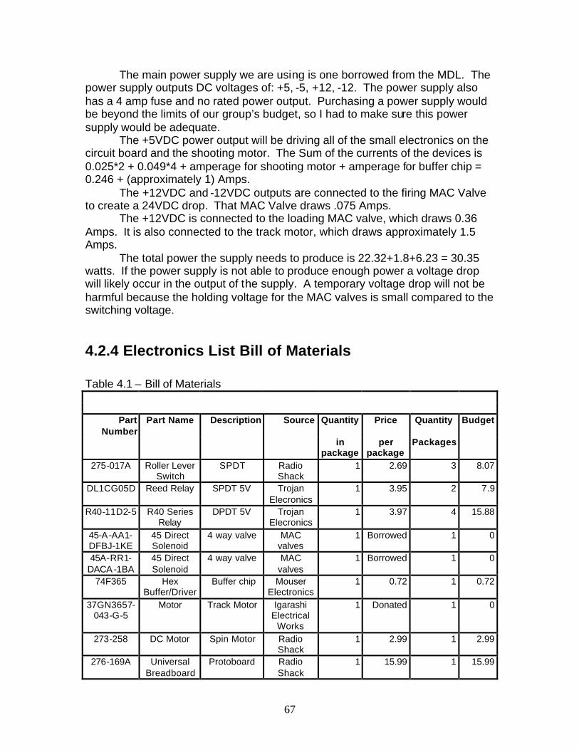
67
The main power supply we are using is one borrowed from the MDL. The power supply outputs DC voltages of: +5, -5, +12, -12. The power supply also has a 4 amp fuse and no rated power output. Purchasing a power supply would be beyond the limits of our group’s budget, so I had to make sure this power supply would be adequate.
The +5VDC power output will be driving all of the small electronics on the circuit board and the shooting motor. The Sum of the currents of the devices is 0.025*2 + 0.049*4 + amperage for shooting motor + amperage for buffer chip = 0.246 + (approximately 1) Amps.
The +12VDC and -12VDC outputs are connected to the firing MAC Valve to create a 24VDC drop. That MAC Valve draws .075 Amps.
The +12VDC is connected to the loading MAC valve, which draws 0.36 Amps. It is also connected to the track motor, which draws approximately 1.5 Amps.
The total power the supply needs to produce is 22.32+1.8+6.23 = 30.35 watts. If the power supply is not able to produce enough power a voltage drop will likely occur in the output of the supply. A temporary voltage drop will not be harmful because the holding voltage for the MAC valves is small compared to the switching voltage.
4.2.4 Electronics List Bill of Materials Table 4.1 – Bill of Materials
Part Number
Part Name Description Source Quantity Price Quantity Budget
in package
per package
Packages
275-017A Roller Lever Switch
SPDT Radio Shack
1 2.69 3 8.07
DL1CG05D Reed Relay SPDT 5V Trojan Elecronics
1 3.95 2 7.9
R40-11D2-5 R40 Series Relay
DPDT 5V Trojan Elecronics
1 3.97 4 15.88
45-A-AA1-DFBJ-1KE
45 Direct Solenoid
4 way valve MAC valves
1 Borrowed 1 0
45A-RR1-DACA-1BA
45 Direct Solenoid
4 way valve MAC valves
1 Borrowed 1 0
74F365 Hex Buffer/Driver
Buffer chip Mouser Electronics
1 0.72 1 0.72
37GN3657-043-G-5
Motor Track Motor Igarashi Electrical
Works
1 Donated 1 0
273-258 DC Motor Spin Motor Radio Shack
1 2.99 1 2.99
276-169A Universal Breadboard
Protoboard Radio Shack
1 15.99 1 15.99

68
N/A 22 guage wire
3 colors Radio Shack
3 4.79 1 4.79
N/A DC Power Supply
(+5VDC, -5VDC,
+12VDC, -12VDC)
Borrowed 1 Borrowed 1 0
270-386A "D" Battery Holder
"D" Battery Holder
Radio Shack
1 1.69 1 1.69
23-823 Enercell Plus "D"
"D" Cell Battery
Radio Shack
2 3.99 1 3.99
64-3086 Snap Connectors
Solderless Wire
Connectors
Radio Shack
10 1.69 1 1.69
P600A Plastic Regulator
6Amp Diode Trojan Elecronics
1 1.58 1 1.58
1N4001 Plastic Regulator
1Amp Diode Trojan Elecronics
6 0.1 1 0.6
N/A IBM T22 Laptop Computer
RPI 1 Borrowed 1 0
N/A LabJack U12 input output laptop
interface
LabJack 1 Donated 1 0
WW-010 Linear Taper 1 ohm potentiometer
Trojan Elecronics 1 4.95 1 4.95
MW122A 3 Volt power supply
3 Volt power supply
Trojan Elecronics 1 25.35 1 25.35
Table 4.1 – Electronics Bill of Materials 4.2.5 Conclusion 4.2.5.1 How the Project Turned Out
Through experimentation and analysis I determined that the laptop and LabJack are in no danger of being damaged by the other electronics in the system. The circuit does its job of allowing the laptop to operate the motors and solenoids in a very straight foreword manor. Having a straight forward circuit saves time by allowing the computer program controlling the circuit to be straight forward also. There were no major problems when designing the circuit. 4.2.5.2 Things I Would Have Done Differently The main problem I encountered was not knowing what devices I needed to control until the very late in the overall design process. I should have worked more closely with the mechanical groups so they could incorporate electronic devices that could be controlled by our means. One instance where this would have helped was when the shooting team purchased a servo motor. The servo motor they purchased had no instructions and no online information was available for it. Through testing I was able to make it work, but the signal necessary to control was beyond the abilities of the LabJack we are using. If I

69
had been in closer communication with the other subgroups we would have saved time and money as a whole group. I realize now that all motors and solenoids should be researched by both electronics and mechanical subgroups and discussion should occur before the purchase of each piece used by both subgroups.

70
4.3 Sensor using the CMUcam Keith Lim 4.3.1 Introduction
This section represents what the CMUcam does and how we went about doing it. The CMUcam is the state of the art technology computer vision microprocessor made by students and professors in Carnegie Mellon University. What it does is it tracks difference in color with many great features. The CMUcam was the part of the project that made the realistic return contribution to our project. The functionalities of the CMUcam are:
• Captures pictures at 16.7 frames per second • Tracks position and size of a specific color • Measure the RGB range or YUV statistics of a captured picture • Focus for extended range of vision • Automatically track first object seen • Serial port connection to laptop • Dump an complete image through the serial port • Dump a bitmap showing the shape of the image of the tracked object • Low power for mobile robots • 115,200 / 38,400 / 19,200 / 9,600 baud serial communication • Auto-white balance • 80x143 resolution • Auto-gain option (CMU)
The CMUcam was perfect for what we needed our machine to do with the realistic return. 4.3.2 CMUcam Goals and Process The CMUcam captures positions of the ping pong ball and determine where the next position of the launcher is going to be. This is going to be the stimulated realistic return. The following pages will show the theory and the calculations that were derived to come up with such automated realistic play. Dimensions:
• Camera - 2.25” wide, 1.75” high, 2” deep • Omnivision OV 6620 single chip – 4mm, F2.8 lens

71
Figure 4.4- Picture of CMUcam Figure 4.5 – CMUcam circuit board.
At first, the CMUcam was thought to be placed at the corners of the ping-pong table looking outward. This idea was soon discarded because the whole background would be captured as well. If there was a change of color in the background, the camera would detect that change and think it is the actual ping-pong ball. This would completely ruin the whole goal of the CMUcam. The CMUcam was finally placed above the table looking downward. The CMUcam would then capture the green table with the white stripe in the middle for easy detection of an orange ping-pong ball. The background stays constant while the orange ball moves back and forth. This will create more accurate detections and effective realistic returns. Only one capture with a decent confidence level is needed to determine where the next position is going to be. The projector is projecting the ball in a straight motion. The projector is only allowed to move to three designated locations. From this, we can predict where the ball is going to land on the other side of the table. When the ball is returned and the coordinates are retrieved, the program will draw lines from that predicted point to the captured coordinate. From there, the program will predict whether the ball is moving toward the left, center, or the right position. Then the projector will quickly move to that position for a quick return. Figure 4.6- CMUcam Placement Diagram

72
Figure 4.7 – CMUcam Prediction Line Examples The camera is focused by turning the knob in the front of the camera. The focus of the camera is very sensitive so a small amount of rotations were used each time it was tested for focus. After focusing, even at a height of 3 ½ feet above, it was tracking well with a resolution of 80x143 and a frame rate of 16.7 fps.
Figure 4.8 – CMUcam Lens Focus
The CMUcam has two options for better tracking. One is called Auto-gain. It is an internal control that adjusts the brightness level of the image and normalizes the light and the dark to best suite the environment. If for example the light is turned on and the environment gets brighter, the camera will try to adjust the brightness to dim the overall image. The second option is called White Balance. This corrects the camera’s color gains on a frame by frame basis. The ambient light in your image may not be pure white. In this case, the camera is going
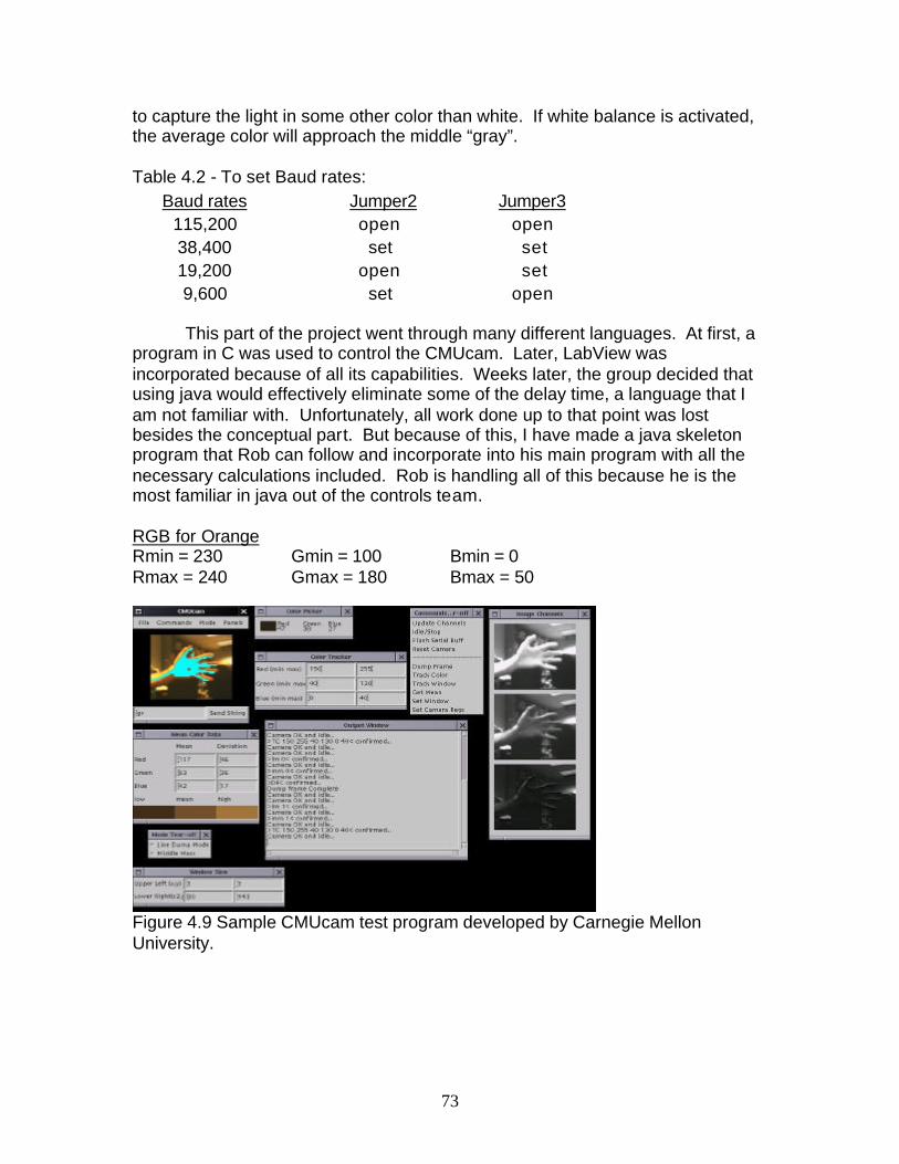
73
to capture the light in some other color than white. If white balance is activated, the average color will approach the middle “gray”. Table 4.2 - To set Baud rates:
Baud rates Jumper2 Jumper3 115,200 open open 38,400 set set 19,200 open set 9,600 set open
This part of the project went through many different languages. At first, a
program in C was used to control the CMUcam. Later, LabView was incorporated because of all its capabilities. Weeks later, the group decided that using java would effectively eliminate some of the delay time, a language that I am not familiar with. Unfortunately, all work done up to that point was lost besides the conceptual part. But because of this, I have made a java skeleton program that Rob can follow and incorporate into his main program with all the necessary calculations included. Rob is handling all of this because he is the most familiar in java out of the controls team. RGB for Orange Rmin = 230 Gmin = 100 Bmin = 0 Rmax = 240 Gmax = 180 Bmax = 50
Figure 4.9 Sample CMUcam test program developed by Carnegie Mellon University.
74
4.3.3 Communication to the CMUcam Here is a list of necessary commands: \r This sets the camera to idle mode. An “ACK” means that it was acknowledged, and a “NCK” means that the command was a failure. DM value \r This sets a delay before a character is transmitted over a serial port. The values that can be passed through range from 0 to 255. GM\r This gets the mean color value in the current image. It is good for auto-tracking and detecting a change of color in a scene L1 value \r This controls the tracking color. Values accepted range from 0 to 2. 0 disables the command. 1 turns on a tracking light. 2 puts the light into a default auto mode. MM mode \r This is called the middle mass mode. This mode is good if you want single point representation of where the object is. A mode value of 0 disengages middle mass, 1 engages middle mass, and 2 engages the mode and turns on the servo pulse width modulation (PWM) signal that ties to center the camera on the center of the color mass. TC [Rmin Rmax Gmin Gmax Bmin Bmax] \r This is used for tracking color. It takes the minimum and maximum RGB values and outputs a type M/C/N data packet. The X values range from 1-80 and the Y values range from 1-143. A confidence greater than 50 would be a strong signal, and lower would lean toward it being a guess. TW \r This tracks the color found in the central region of the current window Here is a list of the output commands: ACK This means that it was successful NCK This means that an error occurred C x1 y1 x2 y2 pixels confidence \r
This is a Type C Packet. It is returned from the colo r tracking command. The x’s and y’s are the boundary of the detected box. The pixels are the number of pixels tracked. The confidence is the number of pixels / area bounded. A high confidence means a strong signal. M mx my x1 y1 x2 y2 pixel confidence \r This is a Type M Packet. This is returned from the color tracking of the middle mass. This is all the same as type C besides the mx and the my. These are for the middle of the mass.

75
4.3.4 Flow Chart
Figure 4.10 Flowchart for the CMUcam
Beginning
Projection Position 1
Projection Position 2
1st portion Equation
1st portion Equation
Projection Position 3
1st portion Equation
2nd portion Equation
2nd portion Equation
2nd portion Equation
1st portion = next position 1 2nd portion = next position 2 3rd portion = next position 3
3rd portion equation
3rd portion equation
3rd portion equation
End
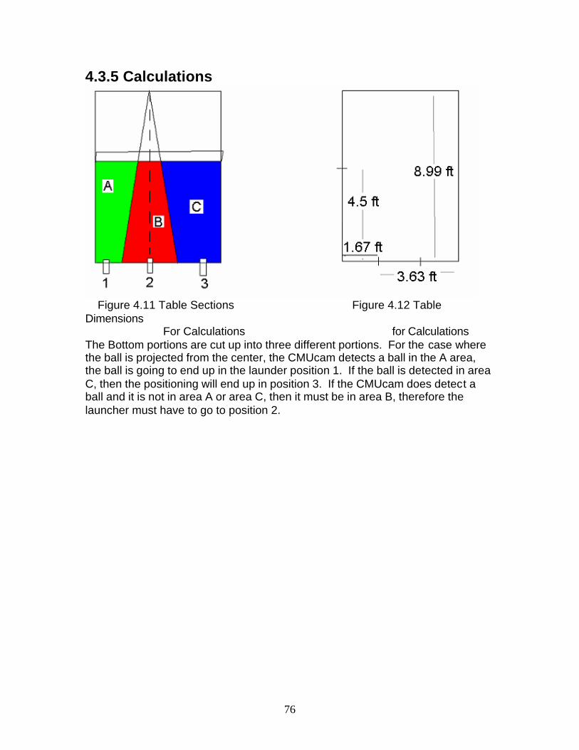
76
4.3.5 Calculations
Figure 4.11 Table Sections Figure 4.12 Table Dimensions For Calculations for Calculations The Bottom portions are cut up into three different portions. For the case where the ball is projected from the center, the CMUcam detects a ball in the A area, the ball is going to end up in the launder position 1. If the ball is detected in area C, then the positioning will end up in position 3. If the CMUcam does detect a ball and it is not in area A or area C, then it must be in area B, therefore the launcher must have to go to position 2.

77
Figure 4.13 Coordinates for the CMUcam Calculations
These are the three cases dealing with the calculation of the prediction line. Each case deals with the three different positions of the launcher. The two lines represent the min and the max for positions 1 and 3. To get the equation for these lines, we need two points. The three points under each case represents the top point and the bottom two. From these we can create 2 equations for each case. If the situation is less than equation 1, then the new position is 1. If the situation is greater than equation 3, then the new position is 3. If it is neither less than 1 nor greater than 3, then it has to be in the middle which is position 2.
equation 1 equation 2 a value b value
case 1 eqn position 1 8.99 = a * .5 + b
0 = 1.67 * a + b -7.096 12.172
case 1 eqn position 2 8.99 = a * .5 + b 0 = 3.63* a + b - 8.513 9.42
case 2 eqn position 1 8.99 = 2.65 * a + b
0 = .55345 * a + b 63.95 -35.39
case 2 eqn position 2 8.99 = 2.65 * a + b
0 = 1.06145 * a + b -33.343 35.39
case 3 eqn position 1 8.99 = 4.8 * a + b
0 = 3.63 * a + b 18.533 -.42
case 3 eqn position 2 8.99 = 4.8 * a + b
0 = 3.65 * a + b 22.83 25.2585

78
final equation programming language equivalence
case 1 eqn position 1
y = -7.096 * x + 12.172
if(y + 7.096 * x) < 12.172 ) then position 1
case 1 eqn position 2 y = -8.513 * x + 9.42
if( (y + 8.513 * x ) > 9.42 ) then position 3
case 2 eqn position 1 y = 63.95 * x – 35.39
if( (y - 63.95 * x) < - 35.39 ) then position 1
case 2 eqn position 2
y = - 33.343 * x + 35.39
if( (y + 33.343 * x) > 35.39 ) then position 3
case 3 eqn position 1 y = 18.533 * x - .42
if( (y - 18.533 * x) < - .42 ) then position 1
case 3 eqn position 2
y = 22.83 * x – 25.2585
if( (y - 22.83 * x) > 25.2585 ) then position 3
Table 4.3 Showing Calculations
The x and y values that are going into these equations aren’t what they should be. From the CMUcam, they come from a resolution of 80x143, which means the x values range from 1-80, and the y’s 1-143. So we must get a ratio and figure out how that ratio coincides with meters. From the x values given, we divide that by 80 then multiply by .853, which is the conversion factor. With y, we divide by 143 then multiply by 1.525. These will give the x and y values that can be put into these equations. Figure 8.10 will clarify what the numbers stand for.
Figure 4.14 Dimensions of the Captured Picture of the CMUcam Another note is that the CMUcam will return a box, which are the x and y values of the corners. With these, just find the average of these points to find the centroids and make the calculation as shown above. This will show whether it is going to position 1, 2, or 3.
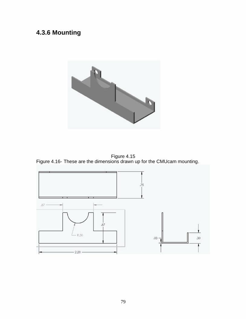
79
4.3.6 Mounting
Figure 4.15
Figure 4.16- These are the dimensions drawn up for the CMUcam mounting.
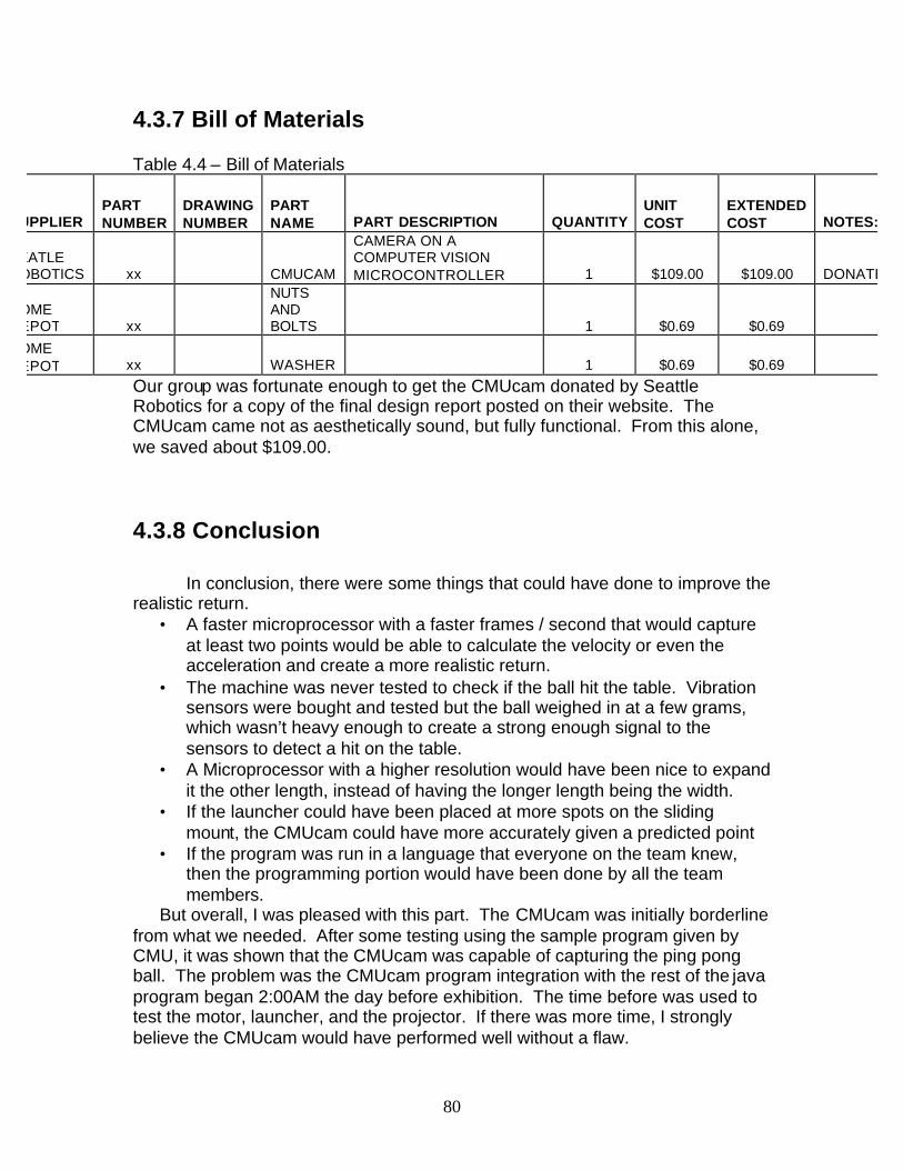
80
4.3.7 Bill of Materials Table 4.4 – Bill of Materials
SUPPLIER PART NUMBER
DRAWING NUMBER
PART NAME PART DESCRIPTION QUANTITY
UNIT COST
EXTENDED COST NOTES:
SEATLE ROBOTICS xx CMUCAM
CAMERA ON A COMPUTER VISION MICROCONTROLLER 1 $109.00 $109.00 DONATED
HOME DEPOT xx
NUTS AND BOLTS 1 $0.69 $0.69
HOME DEPOT xx WASHER 1 $0.69 $0.69
Our group was fortunate enough to get the CMUcam donated by Seattle Robotics for a copy of the final design report posted on their website. The CMUcam came not as aesthetically sound, but fully functional. From this alone, we saved about $109.00. 4.3.8 Conclusion
In conclusion, there were some things that could have done to improve the realistic return.
• A faster microprocessor with a faster frames / second that would capture at least two points would be able to calculate the velocity or even the acceleration and create a more realistic return.
• The machine was never tested to check if the ball hit the table. Vibration sensors were bought and tested but the ball weighed in at a few grams, which wasn’t heavy enough to create a strong enough signal to the sensors to detect a hit on the table.
• A Microprocessor with a higher resolution would have been nice to expand it the other length, instead of having the longer length being the width.
• If the launcher could have been placed at more spots on the sliding mount, the CMUcam could have more accurately given a predicted point
• If the program was run in a language that everyone on the team knew, then the programming portion would have been done by all the team members.
But overall, I was pleased with this part. The CMUcam was initially borderline from what we needed. After some testing using the sample program given by CMU, it was shown that the CMUcam was capable of capturing the ping pong ball. The problem was the CMUcam program integration with the rest of the java program began 2:00AM the day before exhibition. The time before was used to test the motor, launcher, and the projector. If there was more time, I strongly believe the CMUcam would have performed well without a flaw.

81
4.3.9 References www-2.cs.cmu.edu/~cmucam. Carnegie Mellon University. Given the Lab Manual and the sample Java Program. www.parallax.com. Parallax Incorporated. Rocklin, CA. Given a second Lab Manual with additional information. www.seattlerobotics.com. Seattle Robotics. Kent, WA. Company that had donated the CMUcam.
82
Appendix A
Correspondence between LabJackJava expert Chris Reigrut and Robert Van Dyk From: Robert Van Dyk Subj: LabJackJava Date: Apr 2, 2003, 6:11 pm To: LabJack Forum Hey Chris, Nice work with the LabJackJava. After looking through the LabJackJava .java files and I am lost. I realize that you don't want to share your source code, though I can' t figure out how to integrate the LabJackJava software packet into the necessary Java program I will be making to control other video and user interface needs. I don't want to suggest that you setup an extensive help library, though I think it would be helpful if I could get a small amount of direction how to read values off the LabView input ports and write values to the LabView output ports. The reason for this request, I am a student at Rensselaer Polytechnic Institute and I am designing an Augmented Reality Ping Pong Robot and as the software guru of the group I am in charge of programming it. We choose the LabJack because of what it claimed it could do and I choose Java because we need it for interfacing with a second external device and because of LabJackJava. Any help you could provide would be greatly appreciated. Thank you. Robert Van Dyk From: Chris Reigrut Subj: Re: LabJackJava Date: Apr 2, 2003, 11:30 pm To: LabJack Forum Well, the first thing that you will want to do is to run the monitor program as outlined in the readme file to make sure that everything is set up correctly. If it is, you should see the main window with all of your LabJacks listed (if you don't have any LabJacks connected, the window will be empty). Double-clicking on one should open the monitor window, and you should be able to maniuplate the
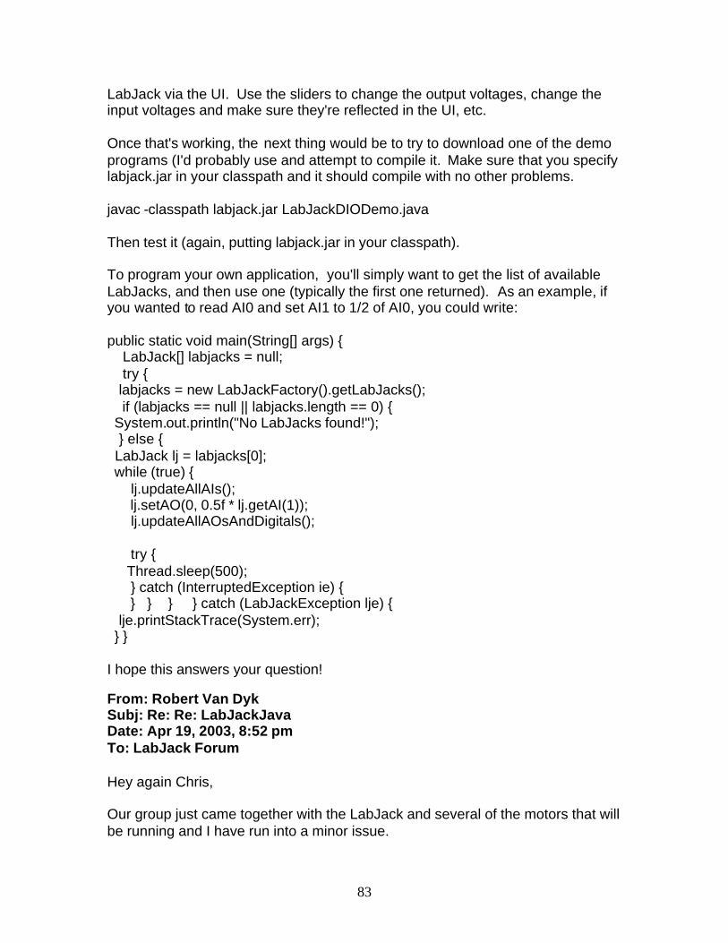
83
LabJack via the UI. Use the sliders to change the output voltages, change the input voltages and make sure they're reflected in the UI, etc. Once that's working, the next thing would be to try to download one of the demo programs (I'd probably use and attempt to compile it. Make sure that you specify labjack.jar in your classpath and it should compile with no other problems. javac -classpath labjack.jar LabJackDIODemo.java Then test it (again, putting labjack.jar in your classpath). To program your own application, you'll simply want to get the list of available LabJacks, and then use one (typically the first one returned). As an example, if you wanted to read AI0 and set AI1 to 1/2 of AI0, you could write: public static void main(String[] args) { LabJack[] labjacks = null; try { labjacks = new LabJackFactory().getLabJacks(); if (labjacks == null || labjacks.length == 0) { System.out.println("No LabJacks found!"); } else { LabJack lj = labjacks[0]; while (true) { lj.updateAllAIs(); lj.setAO(0, 0.5f * lj.getAI(1)); lj.updateAllAOsAndDigitals(); try { Thread.sleep(500); } catch (InterruptedException ie) { } } } } catch (LabJackException lje) { lje.printStackTrace(System.err); } } I hope this answers your question! From: Robert Van Dyk Subj: Re: Re: LabJackJava Date: Apr 19, 2003, 8:52 pm To: LabJack Forum Hey again Chris, Our group just came together with the LabJack and several of the motors that will be running and I have run into a minor issue.

84
I am trying to output two high/low digital signals from IO0 and IO1. I have a LabJack variable called "lj". I have done several variations of method calls with "lj.setD(0, true)" or "lj.setIO(0, false)" and "lj.updateD(0)". I'm guessing that I'm making a pretty easy error, though could you give me a short explanation for using the digital values of the labjack and how do I change the values of IO0 and IO1? Thank you Robert Van Dyk

85
Appendix B
NBB Java Programming code import java.awt.*; import javax.swing.*; import java.io.*; import java.awt.*; import java.awt.image.*; import java.awt.event.*; import java.lang.Object; import java.util.*; import java.lang.*; import java.lang.Object; import com.teravation.labjack.*; public class AnimApp2 extends JComponent implements Runnable { Image[] sw = new Image[22]; // skip 1 Image[] sr = new Image[21]; // skip 3 // 16/20 Image[] sl = new Image[24]; // skip 4 // 15/23 Image[] sc = new Image[21]; // skip 4 // 17/20 Image[] vc = new Image[19]; // skip 1 Image[] vr = new Image[20]; // skip 1 Image[] vl = new Image[23]; // skip 1 Image image; String clip = "sw"; String serve = "s"; boolean centerTrackSwitch; int loop = 0; // controls int loop_after; int frameControlSwitch = 0; String switchToClip; LabJack lj; int frame = 0; boolean high = true; boolean low = false; String mode; String shoot_loc; String next_shoot_loc; // used in CMU code String freq; String serveOrVolley; String pollCMUcam; String runTrack; Date time;

86
Date trackCurr; long trackStart; Date cmuCurr; long cmuStart; Date shooterCurr; long shooterStart; static int trackTravelTime /* in milliseconds */ = 1500; static int timeCMUcamGets = 1500; static int shooterTimeToCrossCourt = 650; CameraImage cImage; int tempVal; AnimApp2 () { shooterStart = 0; cmuStart = 0; trackStart = 0; } public void setupLabJack() { //////////////////////// // CONFIGURE LABJACK // ////////////////////// LabJack[] labjacks = null; try { labjacks = new LabJackFactory().getLabJacks(); if (labjacks == null || labjacks.length == 0) { System.out.println("No LabJacks found!"); } else { lj = labjacks[0]; lj.setIOForOutput(0); // Control for Serving/Volleying // low -> serve position, high -> volley position lj.setIOForOutput(1); // Control for Activating the Piston // off then on... lj.setIOForOutput(2); // Control for Turning the Motor On // low -> on, high -> off lj.setIOForOutput(3); // Control for the Direction the Motor Spins // low -> right, high -> left lj.setIO(0, low);

87
serveOrVolley = "serve"; lj.setIO(1, high ); lj.setIO(2,low); // move Track Motor to the RIGHT/left to begin lj.setIO(3,high); lj.updateIO(3); time = new Date(); trackStart = time.getTime(); trackCurr = new Date(); lj.updateIO(2); while ( (trackCurr.getTime() - trackStart) < trackTravelTime ) { trackCurr = new Date(); } lj.setIO(2,high); lj.updateIO(2); } } catch (LabJackException lje) { lje.printStackTrace(System.err); } } /////////////////////// // CONFIGURE CMUcam // ///////////////////// public void setupCMUcam() { cImage = new CameraImage(160,144, "1"); // Set serial port pollCMUcam = "no"; } /////////////////////////////////////////////// // WHEN YOU CALL REPAINT(), IT RUNS PAINT() // ///////////////////////////////////////////// public void paint(Graphics g) { if (image != null) { // Draw the current image g.drawImage(image, 0, 0, this); } } ////////////////////////////////////////////////////////////////////////// // WHEN (new Thread(app)).start() IS CALLED, run() IS CALLED REPEATEDLY // //////////////////////////////////////////////////////////////////////// public void run() { // Display Loading Screen image = new ImageIcon("ex\\" + "load.jpg").getImage();

88
repaint(); ///////////////////////// // LOAD SWAYING SCENE // /////////////////////// for ( int x = 1; x <= 21; x++ ) { sw[x] = new ImageIcon("sw\\" + x + ".jpg").getImage(); } ///////////////////// // MODE SELECTION // /////////////////// image = new ImageIcon("ex\\" + "mode.jpg").getImage(); repaint(); commWindow cWindow = new commWindow("Mode"); while(cWindow.ready()==0); while ( !cWindow.getPort().equals("Game") && !cWindow.getPort().equals("Target")) { cWindow.getValue("Mode"); while(cWindow.ready()==0); } mode = cWindow.getPort(); //////////////////////////// // CONFIGURE TARGET MODE // ////////////////////////// if ( mode.equals("Target")) { ////////////////////// // SERVE OR VOLLEY // //////////////////// image = new ImageIcon("ex\\" + "s_or_v.jpg").getImage(); repaint(); cWindow.getValue("Serve/Volley "); while(cWindow.ready()==0); while ( !cWindow.getPort().equals("serve") && !cWindow.getPort().equals("volley")) { cWindow.getValue("Serve/Volley"); while(cWindow.ready()==0); } serveOrVolley = cWindow.getPort(); /////////////////////// // SHOOTER LOCATION // ///////////////////// image = new ImageIcon("ex\\" + "loc.jpg").getImage(); repaint();

89
cWindow.getValue("Shooter Location "); while(cWindow.ready()==0); while ( !cWindow.getPort().equals("left") && !cWindow.getPort().equals("center") && !cWindow.getPort().equals("right")) { cWindow.getValue("Shooter Location "); while(cWindow.ready()==0); } shoot_loc = cWindow.getPort(); //////////////// // FREQUENCY // - how long does Gus sway inbetween shots ////////////// image = new ImageIcon("ex\\" + "freq.jpg").getImage(); repaint(); cWindow.getValue("Frequency of Shots "); while(cWindow.ready()==0); while ( !cWindow.getPort().equals("very slow") && !cWindow.getPort().equals("slow") && !cWindow.getPort().equals("medium") && !cWindow.getPort().equals("fast") && !cWindow.getPort().equals("very fast")) { cWindow.getValue("Frequency of Shots "); while(cWindow.ready()==0); } freq = cWindow.getPort(); // Display Loading Screen image = new ImageIcon("ex\\" + "load.jpg").getImage(); repaint(); ///////////////////////////// // LOAD TARGET MODE SCENE // /////////////////////////// if ( serveOrVolley.equals("serve")) { if ( shoot_loc.equals("center") ) { switchToClip = "sc"; for ( int x = 1; x <= 20; x++ ) { System.out.println("load ... sc" + x + ".jpg"); sc[x] = new ImageIcon("sc\\" + x + ".jpg").getImage(); } } else if ( shoot_loc.equals("right") ) { switchToClip = "sr"; for ( int x = 1; x <= 20; x++ ) { System.out.println("load ... sr" + x + ".jpg"); sr[x] = new ImageIcon("sr\\" + x + ".jpg").getImage();} } else // ( shoot_loc.equals("left") ) { switchToClip = "sl"; for ( int x = 1; x <= 23; x++ ) { System.out.println("load ... sl" + x + ".jpg"); sl[x] = new ImageIcon("sl\\" + x + ".jpg").getImage(); } }

90
} else // serveOrVolley.equals("volley")) { if ( shoot_loc.equals("center") ) { switchToClip = "vc"; vc = new Image[18]; for ( int x = 1; x <= 17; x++ ) { vc[x] = new ImageIcon("vc\\" + x + ".jpg").getImage();} } else if ( shoot_loc.equals("right") ) { switchToClip = "vr"; vr = new Image[19]; for ( int x = 1; x <= 18; x++ ) { vr[x] = new ImageIcon("vr\\" + x + ".jpg").getImage(); } } else // ( shoot_loc.equals("left") ) { switchToClip = "vl"; vl = new Image[22]; for ( int x = 1; x <= 21; x++ ) { vl[x] = new ImageIcon("vl\\" + x + ".jpg").getImage(); } } } /////////////////////// // POSITION SHOOTER // ///////////////////// if ( shoot_loc.equals("right") ) { // lj.setIO(3,high); // Load position -> Right // lj.updateIO(3); } else if ( shoot_loc.equals("left")) { try { lj.setIO(2,low); // move Track Motor to the RIGHT/left to begin lj.setIO(3,low); lj.updateIO(3); time = new Date(); trackStart = time.getTime(); trackCurr = new Date(); lj.updateIO(2); while ( (trackCurr.getTime() - trackStart) < trackTravelTime ) { trackCurr = new Date(); } lj.setIO(2,high); lj.updateIO(2); } catch (LabJackException lje) { lje.printStackTrace(System.err);
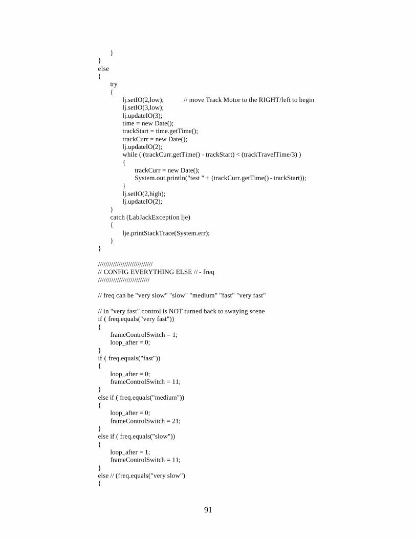
91
} } else { try { lj.setIO(2,low); // move Track Motor to the RIGHT/left to begin lj.setIO(3,low); lj.updateIO(3); time = new Date(); trackStart = time.getTime(); trackCurr = new Date(); lj.updateIO(2); while ( (trackCurr.getTime() - trackStart) < (trackTravelTime/3) ) { trackCurr = new Date(); System.out.println("test " + (trackCurr.getTime() - trackStart)); } lj.setIO(2,high); lj.updateIO(2); } catch (LabJackException lje) { lje.printStackTrace(System.err); } } ///////////////////////////// // CONFIG EVERYTHING ELSE // - freq /////////////////////////// // freq can be "very slow" "slow" "medium" "fast" "very fast" // in "very fast" control is NOT turned back to swaying scene if ( freq.equals("very fast")) { frameControlSwitch = 1; loop_after = 0; } if ( freq.equals("fast")) { loop_after = 0; frameControlSwitch = 11; } else if ( freq.equals("medium")) { loop_after = 0; frameControlSwitch = 21; } else if ( freq.equals("slow")) { loop_after = 1; frameControlSwitch = 11; } else // (freq.equals("very slow") {
92
loop = 1; frameControlSwitch = 21; } } else if ( mode.equals("Game")) { serveOrVolley = "serve"; shoot_loc = "right"; frameControlSwitch = 21; loop = 0; loop_after = 2; clip = "sw"; } ///////////////////////////////// // COUNTDOWN 5...4...3.. .2..1 // /////////////////////////////// try { // Display each image for 1 second image = new ImageIcon("ex\\" + "5.jpg").getImage(); repaint(); Thread.sleep(1000); image = new ImageIcon("ex\\" + "4.jpg").getImage(); repaint(); Thread.sleep(1000); image = new ImageIcon("ex\\" + "3.jpg").getImage(); repaint(); Thread.sleep(1000); image = new ImageIcon("ex\\" + "2.jpg").getImage(); repaint(); Thread.sleep(1000); image = new ImageIcon("ex\\" + "1.jpg").getImage(); repaint(); Thread.sleep(1000); } catch (Exception e) { } int delay = 58; // 17 frames a second (speed of CMUcam) /////////////////////////////////////////////// // LETS PLAY AUGMENTED REALITY TABLE TENNIS // ///////////////////////////////////////////// try { while (true) {
93
///////////////////////// // TIMER OF CMUTOGGLE // /////////////////////// if ( shooterStart > 0 ) { shooterCurr = new Date(); System.out.println("curr = " + shooterCurr.getTime() + " start= " + shooterStart ); if ( ( shooterCurr.getTime() - shooterStart ) > shooterTimeToCrossCourt ) { shooterStart = 0; pollCMUcam = "yes"; cmuStart = time.getTime(); } } ///////////// // CMUcam // /////////// if ( pollCMUcam.equals("yes") ) { tempVal = cImage.trackColor(0); clear(); System.out.println("temp= " + tempVal); cmuCurr = new Date(); tempVal = 144 - tempVal; if ( tempVa l > 0 ) { pollCMUcam = "no"; next_shoot_loc = KeithsPart(tempVal); if ( shoot_loc.equals(next_shoot_loc)) { next_shoot_loc = "none"; serveOrVolley = "volley"; if ( shoot_loc.equals("center") ) { frame = 1; clip = "vc"; } else if ( shoot_loc.equals("right") ) { frame = 1; clip = "vr"; } else { frame = 1; clip = "vl"; } } else if ( (shoot_loc.equals("left") && next_shoot_loc.equals("center")) || (shoot_loc.equals("center") && next_shoot_loc.equals("right")) ) { lj.setIO(2, low);
94
lj.setIO(3, low); lj.updateIO(2); lj.updateIO(3); time = new Date(); trackStart = time.getTime(); shoot_loc = next_shoot_loc; next_shoot_loc = "none"; serveOrVolley = "volley"; if ( shoot_loc.equals("center") ) { clip = "vc"; System.out.println("Next shot is vc"); } else { clip = "vr"; System.out.println("Next shot is vr"); } } else if ( (shoot_loc.equals("right") && next_shoot_loc.equals("center")) || (shoot_loc.equals("center") && next_shoot_loc.equals("left")) ) { lj.setIO(2, low); lj.setIO(3, high); lj.updateIO(3); lj.updateIO(2); time = new Date(); trackStart = time.getTime(); shoot_loc = next_shoot_loc; next_shoot_loc = "none"; serveOrVolley = "volley"; loop_after = 0; if ( shoot_loc.equals("center") ) { clip = "vc"; frame = 1; System.out.println("Next shot is vc"); } else { clip = "vl"; frame = 1; System.out.println("Next shot is vl"); } } } else if ( ( cmuCurr.getTime() - cmuStart) > timeCMUcamGets ) { pollCMUcam = "no"; loop_after = 4; loop = 0; frame = 1; clip = "sw"; serveOrVolley = "serve"; frameControlSwitch = 21; lj.setIO(0, low);
95
lj.updateIO(0); } } //////////// // TRACK // ////////// if ( trackStart > 0 ) { trackCurr = new Date(); if ( (trackCurr.getTime() - trackStart) < trackTravelTime/3 ) { lj.setIO(2,high); lj.updateIO(2); trackStart = 0; } } ////////////////// // SWAYING GUS // //////////////// if ( clip.equals("sw") ) // Precondition : Gus is not in the process of hitting the ball // Midcondition : Gus is swaying back and forth // Postcondition: Control is passed to one of the other videos. { image = sw[frame++]; Thread.sleep(delay*2); //////////////////////// // CHOOSE NEXT SCENE // ////////////////////// if ( mode.equals("Target")) { if ( frame == frameControlSwitch && loop == loop_after ) { frame = 1; clip = switchToClip; loop = 0; } else if ( frame == 21 ) { frame = 1; loop++; } } else if ( mode.equals("Game")) { if ( serveOrVolley.equals("serve") ) { // System.out.println("frame = " + frame + " frameControl = " + frameControlSwitch);
96
// System.out.println("loop = " + loop + " loop_control = " + loop_after); if ( frame == frameControlSwitch && loop == loop_after ) { frame = 1; loop = 0; loop_after = 0; if ( shoot_loc.equals("right")) { clip = "sr"; // System.out.println("Going to sr"); } else if ( shoot_loc.equals("center")) { clip = "sc"; // System.out.println("Going to sc"); } else /* shoot_loc.equals("left")) */ { clip = "sl"; // System.out.println("Going to sl"); } } else if ( frame == frameControlSwitch ) { frame = 1; loop++; } } else /* serveOrVolley.equals("volley") */ { if ( next_shoot_loc.equals("right")) { frame = 1; clip = "sr"; serveOrVolley = "volley"; } else if ( next_shoot_loc.equals("center")) { frame = 1; clip = "sc"; serveOrVolley = "volley"; } else if ( next_shoot_loc.equals("left")) { frame = 1; clip = "sl"; serveOrVolley = "volley"; } else if ( frame == frameControlSwitch ) { frame = 1; } else { frame++;
97
} } } } ////////////////////////// // SERVE FROM THE LEFT // //////////////////////// else if ( clip.equals("sl") ) // Precondition : Gus is serving from the left // Midcondition : Gus makes contact during frame 25/75 // Postcondition: Return to loop { // make sure SERVE SWITCH is configured if ( serveOrVolley.equals("volley") ) { lj.setIO(0, low); lj.updateIO(0); serveOrVolley = "serve"; } if ( mode.equals("Target") ) // 'sl' already in Memory { image = sl[frame++]; Thread.sleep(delay*3); if ( frame == 15 ) { lj.setIO(1, low); lj.updateIO(1); } else if ( frame == 23 ) { frame = 1; if ( !freq.equals("very fast")) clip = "sw"; lj.setIO(1, high); lj.updateIO(1); } } else // Load 'sl' dynamically { image = new ImageIcon("sl\\full\\" + frame + ".jpg").getImage(); frame += 9; if ( frame == 73 ) { lj.setIO(1, low); lj.updateIO(1); shooterStart = time.getTime(); } else if ( frame == 91 ) { lj.setIO(1, high); lj.updateIO(1);

98
} else if ( frame >= 115 ) { frame = 1; clip = "sw"; } } } /////////////////////////// // SERVE FROM THE RIGHT // ///////////////////////// else if ( clip.equals("sr") ) // Precondition : Gus is serving from the right // Midcondition : Gus makes contact during frame 21/62 // Postcondition: Return to loop { // make sure SERVE SWITCH is configured if ( serveOrVolley.equals("volley") ) { lj.setIO(0, low); lj.updateIO(0); serveOrVolley = "serve"; } if ( mode.equals("Target") ) // 'sr' already in Memory { image = sr[frame++]; Thread.sleep(delay*3); if ( frame == 16 ) { lj.setIO(1, low); lj.updateIO(1); } if ( frame == 20 ) { frame = 1; if ( !freq.equals("very fast")) clip = "sw"; lj.setIO(1, high); lj.updateIO(1); } } else // Load 'sr' dynamically { image = new ImageIcon("sr\\full\\" + frame + ".jpg").getImage(); frame += 7; if ( frame == 64 ) { lj.updateIO(1); lj.setIO(1, low); lj.updateIO(1); shooterStart = time.getTime();

99
} else if ( frame == 78 ) { lj.setIO(1, high); lj.updateIO(1); } if ( frame >= 80 ) { frame = 1; clip = "sw"; } } } //////////////////////////// // SERVE FROM THE CENTER // ////////////////////////// else if ( clip.equals("sc") ) // Precondition : Gus is serving from the center. // Midcondition : Gus makes contact during frame 29/84 // Postcondition: Return to loop { // make sure SERVE SWITCH is configured if ( serveOrVolley.equals("volley") ) { lj.setIO(0, low); lj.updateIO(0); serveOrVolley = "serve"; } if ( mode.equals("Target") ) // 'sc' already in Memory { image = sc[frame++]; Thread.sleep(delay*3); if ( frame == 17 ) { lj.setIO(1, low); lj.updateIO(1); } if ( frame == 20 ) { frame = 1; if ( !freq.equals("very fast")) clip = "sw"; lj.setIO(1, high); lj.updateIO(1); } } else // Load 'sc' dynamically { image = new ImageIcon("sc\\full\\" + frame + ".jpg").getImage(); frame += 9; if ( frame == 82 ) {
100
lj.setIO(1, low); lj.updateIO(1); shooterStart = time.getTime (); } else if ( frame == 100 ) { lj.setIO(1, high); lj.updateIO(1); } if ( frame >= 119 ) { frame = 1; clip = "sw"; lj.setIO(1, high); lj.updateIO(1); } } } /////////////////////////// // VOLLEY FROM THE LEFT // ///////////////////////// else if ( clip.equals("vl") ) // Precondition : Gus is volleying from the right. // Midcondition : Gus makes contact during frame 12/22 // Postcondition: Return to loop { // If it is set to serve, set it to volley if ( serve.equals("s") ) { lj.setIO(0, high); lj.updateIO(0); serve = "v"; } if ( mode.equals("Target") ) // 'vl' already in Memory { image = vl[frame++]; Thread.sleep(delay*3); if ( frame == 12 ) { lj.setIO(1, low); lj.updateIO(1); } if ( frame == 21 ) { frame = 1; if ( !freq.equals("very fast")) clip = "sw"; lj.setIO(1, high); lj.updateIO(1); } }

101
else // Load 'vl' dynamically { image = new ImageIcon("vl\\full\\" + frame + ".jpg").getImage(); frame += 4; if ( frame == 21 ) { lj.setIO(1, low); lj.updateIO(1); shooterStart = time.getTime(); } else if ( frame == 29 ) { lj.setIO(1, high); lj.updateIO(1); } else if ( frame >= 42 ) { frame = 1; clip = "sw"; lj.setIO(1, high); lj.updateIO(1); } } } //////////////////////////// // VOLLEY FROM THE RIGHT // ////////////////////////// else if ( clip.equals("vr") ) // Precondition : Gus is volleying from the right. // Midcondition : Gus makes contact during frame 20 // Postcondition: Return to loop { // If it is set to volley, set it to serve if ( serve.equals("s") ) { lj.setIO(0, high); lj.updateIO(0); serve = "v"; } if ( mode.equals("Target") ) // 'vr' already in Memory { image = vr[frame++]; Thread.sleep(delay*3); if ( frame == 11 ) { lj.setIO(1, low); lj.updateIO(1); } if ( frame == 18 ) { frame = 1;

102
if ( !freq.equals("very fast")) clip = "sw"; lj.setIO(1, high); lj.updateIO(1); } } else // Load 'vr' dynamically { image = new ImageIcon("vr\\full\\" + frame + ".jpg").getImage(); frame += 4; if ( frame == 21 ) { lj.setIO(1, low); lj.updateIO(1); shooterStart = time.getTime(); } else if ( frame == 29 ) { lj.setIO(1, high); lj.updateIO(1); } if ( frame >= 36 ) { frame = 1; clip = "sw"; lj.setIO(1, true); lj.updateIO(1); } } } ///////////////////////////// // VOLLEY FROM THE CENTER // /////////////////////////// else if ( clip.equals("vc") ) // Precondition : Gus is volleying from the center. // Midcondition : Gus makes contact during frame 19 // Postcondition: Return to loop { // If it is set to volley, set it to serve if ( serve.equals("s") ) { lj.setIO(0, high); lj.updateIO(0); serve = "v"; } if ( mode.equals("Target") ) // 'vc' already in Memory { image = vc[frame++]; Thread.sleep(delay*3); if ( frame == 10 ) { lj.setIO(1, low);
103
lj.updateIO(1); } if ( frame == 17 ) { frame = 1;if ( !freq.equals("very fast")) clip = "sw"; lj.setIO(1, high); lj.updateIO(1); } } else // Load 'vc' dynamically { image = new ImageIcon("vc\\full\\" + frame + ".jpg").getImage(); frame += 4; if ( frame == 21 ) { lj.setIO(1, low); lj.updateIO(1); shooterStart = time.getTime(); } else if ( frame == 29 ) { lj.setIO(1, high); lj.updateIO(1); } if ( frame >= 34 ) { frame = 1; clip = "sw"; lj.setIO(1, high); lj.updateIO(1); } } } // Causes the paint() method to be called repaint(); } } catch (Exception e) { } } /////////////////// // KEITH'S PART // ///////////////// public String KeithsPart(int y) { if ( shoot_loc.equals("right")) { if ( y > 100 ) {

104
return "right"; } else { return "center"; } } else if ( shoot_loc.equals("center")) { if ( y < 55 ) { return "left"; } else if ( y > 89 ) { return "right"; } else { return "center"; } } else { if ( y < 44 ) { return "left"; } else { return "center"; } } } private void clear() { int cnt; for(cnt=0; cnt<100; cnt++ ) { try{ Thread.sleep(125); } catch(Exception blah){} if(cImage.idle()) break; } if(cnt==99) System.out.println("<clear> time out" ); cImage.flushBuf(); } public static void main(String[] args) { AnimApp2 app = new AnimApp2(); app.setupLabJack();

105
app.setupCMUcam(); JFrame frame = new JFrame(); frame.setSize(720, 480); frame.setTitle("Nothing But Balls"); frame.setResizable(false); frame.show(); frame.setLocation(0, 0); frame.getContentPane().add(app); frame.setVisible(true); (new Thread(app)).start(); } } class commWindow extends Canvas { Frame comm_f; Panel comm_p; TextField comm_t; Dialog comm_d; int done; commWindow(String foo) { done=0; comm_f = new Frame(); comm_p= new Panel(); comm_t = new TextField("", 25); Button comm_b = new Button("Ok"); comm_b.addActionListener( new ActionListener() { public void actionPerformed(ActionEvent e) { done=1; } } ); comm_d = new Dialog(comm_f,foo + " Select"); comm_p.add(comm_t); comm_p.add(comm_b); comm_d.add(comm_p); comm_d.setSize(450,62); comm_d.show(); } public void getValue(String foo) { done=0; comm_f = new Frame(); comm_p= new Panel(); comm_t = new TextField("", 25); Button comm_b = new Button("Ok"); comm_b.addActionListener( new ActionListener() { public void actionPerformed(ActionEvent e)

106
{ done=1; } } ); comm_d = new Dialog(comm_f,foo + " Select"); comm_p.add(comm_t); comm_p.add(comm_b); comm_d.add(comm_p); comm_d.setSize(450,62); comm_d.show(); } public String getPort() { return comm_t.getText (); } public int ready() { if(done==0) return 0; comm_d.setVisible(false); return 1; } } ///////////////////////////////////////////////// // CAMERAIMAGE RUNS CMUCAM TRACK COLOR METHOD // /////////////////////////////////////////////// class CameraImage extends Canvas implements Serializable { public int mm; int mmx,mmy,mmoldx,mmoldy; char bmask[][]; int lm,lmIndex,tc; int width,height; int pixels[]; int col,row; int mx,my,xcoord,ycoord,zcoord,oldz,oldx,o ldy,x2coord,y2coord,oldx2,oldy2,conf; MemoryImageSource source; int frames,fps; long startTime; int start; int scale; long wdTimer; serialComm mySerial; CameraImage(int x,int y,String commPort) { // This sets up the serial communication object // all of the read/write commands get called from here mySerial=new serialComm("1"); // Lets clear some variables... bmask= new char[10][48]; lmIndex=0; mmoldx=0; mmoldy=0;

107
mmx=0; mmy=0; mm=1; lm=0; scale=0; start=1; zcoord=0; xcoord=0; ycoord=0; x2coord=0; y2coord=0; oldx=0; oldy=0; oldx2=0; oldy2=0; oldz=0; conf=0; tc=0; col=0; row=0; // this.setBackground(Color.black); width=x; height=y; /* pixels=new int[width*height]; source = new Memo ryImageSource(width,height,pixels,0,width); source.setAnimated(true); image=createImage(source); */ frames=0; fps=0; Date time = new Date(); startTime=time.getTime(); } public int trackColor(int mode) { int data; if(!sendCommand("TC 220 240 80 160 15 17\r"))return 0; try{ data=mySerial.readByte(); if(data==0xFE) // Ignore a line mode mean packet { data=mySerial.readByte(); while(data!=0xFD) data=mySerial.readByte(); } if(data=='C' || data=='M' || data==0xAA) { tc=1; if(data==0xAA) lm=1;

108
else lm=0; lmIndex=0; if(lm==1) // Read in the bitmap for lm { try{ data=0; int index=0; Date time = new Date(); wdTimer=time.getTime(); while(data!=0xAA) { data=mySerial.readByte(); //(char)sPortIn.read(); bmask[index][lmIndex]=(char)data; index++; if(index==10) { index=0; lmIndex++; } Date time2 = new Date(); if(time2.getTime()-wdTimer>1000) {System.out.println("<Track> time out"); return 0; } } data=mySerial.readByte();//(char)sPortIn.read(); if(data!=0xAA) { System.out.println( "Line Mode Termination Error" ); } } catch(Exception e) {} data=mySerial.readByte(); data=mySerial.readByte(); if(data=='S') return 2; } if(data=='M') // If middle mass is on mm=1; else mm=0; data=mySerial.readByte(); if(mm==1) { mmx=mySerial.readNum(); mmy=mySerial.readNum(); } xcoord=mySerial.readNum(); ycoord=mySerial.readNum(); x2coord=mySerial.readNum(); y2coord=mySerial.readNum(); zcoord=mySerial.readNum(); conf=mySerial.readNum(); frames++; Date time = new Date(); if( time.getTime()-startTime>1000 )

109
{ fps = frames; frames=0; startTime=time.getTime(); } /*if(lm==0)*/ System.out.println( "x1="+ (new Integer(xcoord)).toString()+" y1="+ (new Integer(ycoord)).toString()+" x2="+ (new Integer(x2coord)).toString()+" y2="+ (new Integer(y2coord)).toString()+" size="+ (new Integer(zcoord)).toString() + " fps="+ (new Integer(fps)).toString()+" conf="+ (new Integer(conf)).toString() ); xcoord*=2; xcoord=160-xcoord; x2coord*=2; x2coord=160-x2coord; ycoord=144-ycoord; y2coord=144-y2coord; } }catch(Exception e) { System.out.println(e);} return ycoord; } int getx1() { return xcoord; } int gety1() { return ycoord; } int getx2() { return x2coord; } int gety2() { return y2coord; } /* Flushes all data out of the serial file buffer */ public void flushBuf() { char a; try { while(mySerial.readNonBlock()!=0); // used to be an available } catch(Exception e) { System.out.println(e); } } /* Trys to get the camera to settle down and idle */ public boolean idle() { char a,c,k,r,p; try { Date time = new Date(); wdTimer=time.getTime(); mySerial.writeStr("\r"); while(true) {

110
a=mySerial.readByte(); if(a==':' ) { start=1; xcoord=0; ycoord=0; x2coord=0; y2coord=0; zcoord=0; repaint(); // System.out.println("Camera OK and idle..." ); return true; } Date time2 = new Date(); if(time2.getTime()-wdTimer>1000) {System.out.println("<idle> time out"); return false; } } }catch(Exception e) {System.out.println(e);} return false; } /* Sends a command and checks for an ACK Returns 1 if ACK else 0 */ public boolean sendCommand(String command) { char a,c,k,r; a=0; try { mySerial.writeStr(command); a=mySerial.readByte(); c=mySerial.readByte(); k=mySerial.readByte(); r=mySerial.readByte(); if(a=='A' && c=='C' && k=='K' && r=='\r' ) { // System.out.println( ">" + command.trim() + "< confirmed..." ); start=0; return true; } else { System.out.println( ">" + command.trim() +"< failed..." ); start=1; return false; } }catch(Exception e) {System.out.println(e);} return false; } }

111
////////////////////////////////////////////////////////////////////////// // SERIALCOMM COMMUNICATES BETWEEN TRACK COLOR COMMAND AND SERIAL PORT // //////////////////////////////////////////////////////////////////////// class serialComm { serialComm(String commPort) { int error; error = serialPort.openSerial(new Integer(commPort).intValue(), 5); if (error != 0) { System.err.println("Error " + error + " during openSerial()"); System.exit(0); } serialPort.setReadTimeout(125); //Illah - make this much smaller? System.out.println("serial port successfully opened!"); } /* Reads in an ascii number and returns an int. This function blocks. */ public int readNum() { char one,two,three,four; one=readByte(); two=readByte(); if( two==' '|| two=='\r' ) return((int)(one-'0')); three=readByte(); if( three==' ' || three=='\r' ) return((int)(one-'0')*10+(two-'0')); four=readByte(); return((int)(one-'0')*100+(two-'0')*10+(three-'0')); } public char readByte() { Date time = new Date(); long wdTimer=time.getTime(); int val=-1; while(val==-1) { val = serialPort.readByte(); Date time2 = new Date(); if(time2.getTime()-wdTimer>1000) { System.out.println("<Serial Read> time out");
112
return 0; } } return((char)val); } public char readNonBlock() { int val; val = serialPort.readByte(); if(val==-1) val=0; return((char)val); } public void writeStr(String in) { int i; byte[] bytes = in.getBytes(); for (i = 0; i < bytes.length; i++) { int error = serialPort.sendByte(bytes[i]); if (error != 0) { System.out.println( "Serial Send error" ); break; } } } } ////////////////////////////////////////////////////////////////// // SERIAL PORT OPENS A CHANNEL BETWEEN THIS PROGRAM AND CMUCAM // //////////////////////////////////////////////////////////////// class serialPort extends java.lang.Object { // open serial port at specified baud with other appropriate parameters. // returns: // 0 on success // -1 on failure to open serial port // -2 on failure to read port state // -3 on failure to set port state // coms are: 1 = "COM1"; 2 = "COM2" et cetera // baud rates are: 1 = 9600; 2=19200; 3=38400; 4=57600; 5=115200; 6=230400 public synchronized native static int openSerial(int comNum, int baudSpec); public synchronized native static int closeSerial(); // returns 0 on success or -1 on failure to send byte public synchronized native static int sendByte(int theByte); // initialTimeout is measured in milliseconds // // returns -6 on failure to set timeout, 0 on success public synchronized native static int setReadTimeout(int initialTimeout); // returns -1 in error or timeout, else returns int between 0 and 255

113
public synchronized native static int readByte(); static { System.loadLibrary("sserial"); } }
114
Appendix C: Java Skeleton Program for CMUcam import java.awt.*; //declaring libraries import java.awt.image.*; import java.awt.event.*; import java.lang.*; import java.lang.Object; mport java.util.*; import java.util.EventListener; import java.io.*; public class cmucam extends Canvas { /////////////////////////INITIALIZING////////////////////////////////////// TextField rMin,rMax,gMin,gMax,bMin,bMax; //initializing variables cmucam() { //set autogain on, track RGB color on, 17 f/s int color_mode=44; //returned from camsettings //for RGB settings int fps = 17; //for frames per seconds int gain = 32; //for autogain //set track color rMin = 230; //returned from color tracking //for configuring red rMax = 240; gMin = 130; //for configuring green gMax = 170; bMin = 10; //for configuring blue bMax = 50; //turn on tracking CImage = new CameraImage ( 160, 144, cWindow.get.Port()); CImage track; //variable for delay int y=0; ////////////////////////MAIN FUNCTION////////////////////////////////// while(1) { //if after 2 sec of projection it doesn't detect color if(!Detect() && y != 10000) //if it doesn't detect and it hasn't been given //ample time for the ball to get hit back { y++; //increment y } else if(!Detect() && y==10000) //checks cmucam for track //if it hasn't been detected after some time { then
115
set score lower for player gus hitting a serve from a random side Right/middle/left project from the corresponding side } else //if all the if's are not true //so if it is detected { call calculations(); for(int x=0; x<10000; x++); //delay for a sec } } } /////////////////////TRACKING COLOR///////////////////////////////// public int trackColor(int mode) { int data; if(start==1) { if(mode==0) { if(!sendCommand(myTrack.sendString()))return 0; } else { if(!sendCommand("tw" + "\r")) return 0; } } try{ //data=sPortIn.read(); data=mySerial.readChar(); if(data==0xFE) // Ignore a line mode mean packet { data=mySerial.readChar(); while(data!=0xFD) data=mySerial.readChar(); } if(data=='C' || data=='M' || data==0xAA) { tc=1; if(data==0xAA) lm=1; else lm=0; lmIndex=0; if(lm==1) // Read in the bitmap for lm { try{ data=0; int index=0; Date time = new Date(); wdTimer=time.getTime(); while(data!=0xAA)

116
{ data=mySerial.readByte(); //(char)sPortIn.read(); bmask[index][lmIndex]=(char)data; index++; if(index==10) { index=0; lmIndex++; } Date time2 = new Date(); if(time2.getTime()-wdTimer>1000) {System.out.println("<Track> time out"); return 0; } } data=mySerial.readByte();//(char)sPortIn.read(); if(data!=0xAA) { System.out.println( "Line Mode Termination Error" ); } } catch(Exception e) {} data=mySerial.readChar(); data=mySerial.readChar(); if(data=='S') return 2; } if(data=='M') // If middle mass is on mm=1; else mm=0; data=mySerial.readChar(); if(mm==1) { mmx=readNum(); mmy=readNum(); } xcoord=readNum(); ycoord=readNum(); x2coord=readNum(); y2coord=readNum(); zcoord=readNum(); conf=readNum(); frames++; Date time = new Date(); if( time.getTime()-startTime>1000 ) { fps = frames; frames=0; startTime=time.getTime(); } /*if(lm==0)*/ outWin.append("x1="+ (new Integer(xcoord)).toString()+" y1="+ (new Integer(ycoord)).toString()+" x2="+ (new Integer(x2coord)).toString()+" y2="+ (new Integer(y2coord)).toString()+" size="+

117
(new Integer(zcoord)).toString() + " fps="+ (new Integer(fps)).toString()+" conf="+ (new Integer(conf)).toString() ); //xcoord*=4.4; xcoord*=2; xcoord=160-xcoord; //x2coord*=4.4; x2coord*=2; x2coord=160-x2coord; ycoord=144-ycoord; y2coord=144-y2coord; repaint(); } }catch(Exception e) { System.out.println(e);} return 2; } ///////////////////////////CALCULATIONS//////////////////////////////// // calculations for the prediction line if((conf > 40) && (size < 100)) //if confidence of tracking is good and size of square tracked is small { position=0; //initializing final position to 0 Y = (ycoord + y2coord) / 2 / 80 * .853; // find centroid of object X = (xcoord + x2coord) / 2 / 143 * 1.525; //prediction pt if(Launcher == 1) // if launcher is at position 1 { if(y + 7.096 * x) < 12.172 ) {position = 1;} else if( (y + 8.513 * x ) > 9.42 ) {position = 3;} else {position = 2;} } else if(Launcher == 2) { if( (y - 63.95 * x) < - 35.39 ) {position = 1;} else if( (y + 33.343 * x) > 35.39 ) {position = 3;} else {position = 2;} } else { if( (y - 18.533 * x) < - .42 ) {position = 1;} else if( (y - 22.83 * x) > 25.2585 ) {position = 3;}
118
else {position = 2;} } if(position1) gus hitting back on the left side project from left side if(position2) gus hitting back on the middle side project from the middle side if(position3) gus hitting back on the right side project from the right side after video is completed, gus in the middle again } }

119

120
Drawing Tree Table 5.1 Dominic Lin 1) Team Concept Design
A1) Metal Support Structure A1a) Bottom Strut A1b) Sidewalls A1c) Support Beam A1d) Gusset A1e) Leg
A2) Cart Assembly (Exploded View) A2a) Cart Body A2b) Cart Wheel A2c) Cart Pin A2d) Cart Retainer Extender A2e) Cart Retainer
A3) Pulley Assembly (Exploded) A3a) Pulley Wheel Assembly (Exploded) A3ai) Pulley Face A3aii) Pully Wheel
B1) Firing System Assembly (Collapsed) B2) Firing System Assembly (Exploded) B3) <Firing Subcomponent>*
B3a) Firing Unit Assembly Exploded B3b) Firing Wheel Assembly (Exploded) B3bi) Firing Wheel Bracket B3c) <Barrel Drawings>* B3ci) Barrel B3cii) Barrel 2 B3d) End Cap B3e) Shooter Base
B4) <Manifold Subcomponent>* B4a) Manifold Assembly (Exploded) B4b) Manifold Part B5) <Ball Feed Subcomponent)* B5a) Ball Feed Assembly (Collapsed) B5b) Ball Feed Assembly (Exploded) B5c) Loader Shield B5d) Hopper Holder B5e) Ball Hopper B5f) Piston Assembly (Exploded) B5fi) Piston End B5g) Poston Bracket B5h) Hopper Stabilizer
121
B5i) Lexan Hopper Top Stabilizer B6) <Serving Subcomponent>* B6a) Serving Unit Assembly (Collapsed) B6b) Serving Unit Assembly (Exploded) B6c) Hinge Mechanism Assembly (Exploded) C1) Screen Structure Assembly (Collapsed & Exploded) C1a) <Ball Head Unit>* C1ai) Ball Head Assembly (Collapsed) C1aii) Ball Head Assembly (Exploded) C1b) CMU CAM Arm C1c) Copper Screen Support Pipe C1d) Vertical Pipe C1e) Vertical Pipe Support C1d) Vertical Pipe Support Clamp *Not actual Drawings. It is indicating a categ