Title Inelastic Behavior of Full-Scale Steel Frames with ...
24
RIGHT: URL: CITATION: AUTHOR(S): ISSUE DATE: TITLE: Inelastic Behavior of Full-Scale Steel Frames with and without Bracings WAKABAYASHI, Minoru; MATSUI, Chiaki; MINAMI, Koichi; MITANI, Isao WAKABAYASHI, Minoru ...[et al]. Inelastic Behavior of Full-Scale Steel Frames with and without Bracings. 1974-03 http://hdl.handle.net/2433/124840
Transcript of Title Inelastic Behavior of Full-Scale Steel Frames with ...

RIGHT:
URL:
CITATION:
AUTHOR(S):
ISSUE DATE:
TITLE:
Inelastic Behavior of Full-ScaleSteel Frames with and withoutBracings
WAKABAYASHI, Minoru; MATSUI, Chiaki; MINAMI,Koichi; MITANI, Isao
WAKABAYASHI, Minoru ...[et al]. Inelastic Behavior of Full-Scale SteelFrames with and without Bracings.
1974-03
http://hdl.handle.net/2433/124840
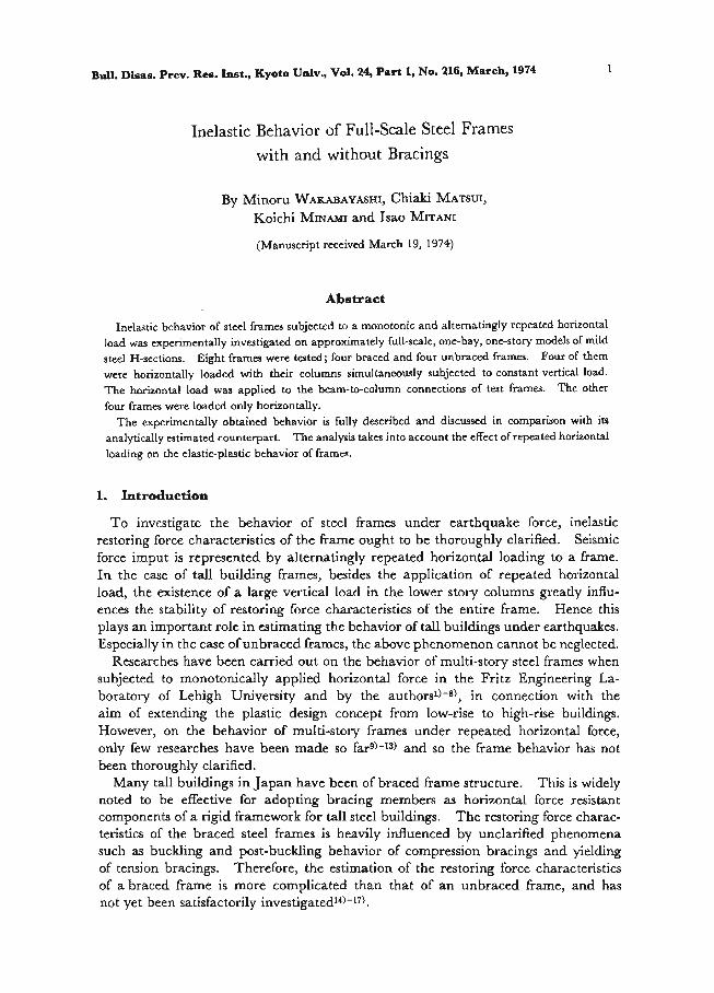
Bull. Disas. Prey. Res. Inst., Kyoto Univ., Vol. 24, Part 1, No. 216, March, 1974 1
Inelastic Behavior of Full-Scale Steel Frames
with and without Bracings
By Minoru WAKABAYASHI, Chiaki MATSUI, Koichi MINMU and Isao MrrANI
(Manuscript received March 19, 1974)
Abstract
Inelastic behavior of steel frames subjected to a monotonic and alternatingly repeated horizontal load was experimentally investigated on approximately full-scale, one-bay, one-story models of mild
steel H-sections. Eight frames were tested; four braced and four unbraced frames. Four of them were horizontally loaded with their columns simultaneously subjected to constant vertical load. The horizontal load was applied to the beam-to-column connections of test frames. The other four frames were loaded only horizontally.
The experimentally obtained behavior is fully described and discussed in comparison with its analytically estimated counterpart. The analysis takes into account the effect of repeated horizontal
loading on the elastic-plastic behavior of frames.
1. Introduction
To investigate the behavior of steel frames under earthquake force, inelastic restoring force characteristics of the frame ought to be thoroughly clarified. Seismic force imput is represented by alternatingly repeated horizontal loading to a frame. In the case of tall building frames, besides the application of repeated horizontal load, the existence of a large vertical load in the lower story columns greatly influ-ences the stability of restoring force characteristics of the entire frame. Hence this
plays an important role in estimating the behavior of tall buildings under earthquakes. Especially in the case of unbraced frames, the above phenomenon cannot be neglected.
Researches have been carried out on the behavior of multi-story steel frames when subjected to monotonically applied horizontal force in the Fritz Engineering La-boratory of Lehigh University and by the authors0-8), in connection with the aim of extending the plastic design concept from low-rise to high-rise buildings. However, on the behavior of multi-story frames under repeated horizontal force, only few researches have been made so far9)-13) and so the frame behavior has not been thoroughly clarified.
Many tall buildings in Japan have been of braced frame structure. This is widely noted to be effective for adopting bracing members as horizontal force resistant components of a rigid framework for tall steel buildings. The restoring force charac-teristics of the braced steel frames is heavily influenced by unclarified phenomena such as buckling and post-buckling behavior of compression bracings and yielding
of tension bracings. Therefore, the estimation of the restoring force characteristics of a braced frame is more complicated than that of an unbraced frame, and has
not yet been satisfactorily investigated10-17).

2 M. WAKABAY ASIA C. MATSUI, K. MINAMI and L MITANI
Experiments described in this paper were to investigate the hysteretic behavior of unbraced and braced steel frames as well as that under monotonic loading. There were four each of unbraced and braced test frames, four of which were tested under large constant vertical load on the columns in order to make it possible to know the behavior of lower stories of tall buildings.
Also presented in this paper are the results of elastic-plastic analysis of unbraced and braced steel frames. Then the analysis is compared with the test results. It was found from this study that the behavior of test frames were satisfactorily predic-table by the theoretical analysis presented.
2. Tests and Test Results
2.1 Description of Tests
Experiments were done on the large-scale model portal frames shown in Fig. 1. Their dimensions and loading conditions are given in Table 1. The story height and the span of these test frames were approximately those of actual building frames but the ratio of the story height to the radius of gyration of the column section was
chosen to be slightly larger in the test frames than reality. This modification on the large scale test frames was to clearly learn the frame instability phenmenon due to the coupled effect of the frame sway and the vertical load, P- a, effect. Horizontal
.2.40 159 4 100 ======.:
1/4-,___thEDOS25132_9_
I
cl P:11
1-315 tenni 5001=1
(A) UNBRACED FRAME
..======.
001a)
CO BRACED FRAME
Fig. I. Test Frames.

Inelastic Behavior of Full-Scale Steel Frames with and without Bracings 3
Table. 1 Dimensions and loading conditions of test frames
Specimen Prpippiph 11h,Column Beam Bracing 4 x h Loading Name (ton)'e(cm) (C111)1I (mm) (mm) (mm) x I Conditions
H-175 x 175 H-250 x 125 FM 0 0 0 260 500 34.7 0.768 Monotonic x7 .5x11 x 6x9 FM 5 70 0.489,0.12 u n 34.7 n n 0.742
FC 0 0 0 0 n n 34.5 n n 0.737 Repeated FC 5 70 0.516 0.12 n n 34.5 n I/ 0.745
H-175 x 175 H-250 x 125 H-100 x 50 BM 0 0 0 260 500 34.40.756 Monotonic x 7.5x11 X 6 x 9 x 4x6 BM 5 70 0.542 t. u 34.61 n ri n 0.736
BC 0 0 0 ri ri 35.0 n t/ n 0.741 Repeated BC 5 70 0.557 u n 34.8 n n is 0.746 it
P: column load, P6: elastic buckling load of frame, P„: yeild load of column, h: column height, /: beam length, r: radius of gyration of a column cross section, I: sectional moment of inertia, 4 x hlyex1): beam-to-column stiffness ratio.
load was monotonically applied on the four frames and alternatingly repeated on the other four; two of each with the vertical load acting constantly.
2.2 Test Frames
All the test frames were built up by welding using rolled H-shape members of SS41 steel. Beam-to-column connection panels were reinforced by diagonal stiffeners
and the column base beam was reinforced by doubler plates, as shown in Fig. 1, to
prevent the panel plates from yielding under shear prior to the yeilding of the column and/or beam members by flexure. Steel plate pieces were attached on a test frame at a total of seven locations; two at beam-to-column junctures, mid point and 1/5
points of beam and mid points of two columns. At these locations, the lateral sup-porting units, which will be refered to later in this paper, were bolted to the test frame to prevent the frame from lateral buckling.
Cross-sectional properties of frame members are tabulated in Table 2. These
Table 2. Actual section properties of frame members
Specimen Column Beam Bracing
Name A I Z Z„ A I Z14,A1I Z Z,, (cm') (cm")I(cm') (cm') (cm2) (cm') (cm°) (cm') (cm')I (cm') (cm') (cm') FM 0 48.8 2740 314 351 37.9 4050 325 367 / FM 5 50.6 2840 323 363 37.3 4050 322 363
FC 0 50.8 2880 328 366 38.3 4080 326 370
FC 5 50.2 2840 324 362 37.6 4070 325 367 / BM 0 50.5 2825 326 363 37.7 4036 322 365 10.1 I 11.4 4.57 7.41
BM 5 50.7 2868 328 366 37.9 4058 323 366 10.9 13.0 5.17 8.35
BC 0 50.7 2804 323 361 37.7 4048 322 365 10.9 13.3 5.28 8.49
BC 5 50.6 2821 324 362 37.3 4046 322 364 10.5 12.2 4.81 7.83
A: cross-sectional area I: sectional moment of inertia Z: section modulus Z,: plastic section
modulus

4 M. WAKABAYASHI, C. MATSUI, K. MINAMI and L MITANI
values were calculated from the actually measured dimensions of each member.
The mechanical properties of the frame material are shown in Table 3.
Table 3. Mechanical properties of test frame material
Sped- Column Beam Brace men
NameayIas1e„,E1E6. i 6.1suletsIE,Ea1anIad, t/cm2)(t/cm2)(%)1le"2eY",,(t/cm2)(t/cms)(%)1"I11551i(t/cm2)(t/cm2);(%)e"2asl1",,"1"',,,
FM 0 2.70 4.42 29.3 14.0 0.016 2.70 4.23 26.51 15.7 0.013 / FM 5 2.78 4.44 32.2 13.7 0.014 2.88 4.35 30.5 14.9 0.013
FC 0 2.68 4.28 34.1 15.7 0.014 2.86 4.18 25.6 12.1 0.011
FC 5 2.70 4.31 34.4 15.2 0.010 2.56 3.95 24.6 13.6 0.011/ / / BM 0 2.53 4.23 28.1 14.5 0.014 2.75 4.08 27.8 13.2 0.011 2.93 4.61 25.3 14.5 0.013
BM 5 2.55 4.16 31.8 11.2 0.012 2.85 4.25 27.0 11.5 0.012 3.28 4.75 25.6 15.2 0.011
BC 0 2.66 4.39 30.6 12.2 0.015 2.86 4.19 24.7 13.4 0.012 3.25 4.60 23.1 14.2 0.011
BC 5 2.48 4.14 30.7 14.0 0.013 3.28 4.17 27.1 12.5 0.011 2.93 4.32 26.41 16.6 10.012 a„ : yield stress, au: tensile strength, E.: maximum strain a,: strain at yield stress,
an: strain at the onset of strain hardening, E: modulus of elasticity, E,,: strain hardening modulus.
2.3 Loading System and Loading Program
The loading system is illustrated in Fig. 2 and Photo. 1. In Fig. 2, the test frame
f / 100100 ArntISO ) test frame
1
I test bed anchor block •.vertical loading frame
_
1II ®vertical loading frame 11 ® horizontal loading frame lateral supporting frame
iII ®
, ©lateralsupporting unit ®Of
!::. 01§iloal cell ="41 rollers 1
s.+ anchor bolt
-.1 I.70 04‘WPala:.77.111%,. II=
1' IMMIMINIMII= - ̂1 1101111!I111\- em(I)! t ,1lirisiTVISMartialliInitL_A^71
-® in=Iii 2176vitFir,0AmiN 0 0MEE
111:::1112=-= as! p: s lin1171010 •1" M HI MIT = 1{1'''WI0aNES •1111:11=-,IN:= ===.1n BN.inti Kl=1MO.00li Ihn!
A
Fig. 2. (a)

Inelastic Behavior of Full-Scale Steel Frames with and without Bracings 5
•
H® it 67i)CO
1
of
0 11 11'1 14)
Ha.EM.1•=• DI' 0111— 1I
1011IM Bala
01 // 0 r/ I ,/ (b) A–A section (c) B–B section
Vertical loading frame. Lateral supporting frame.
Fig. 2. Loading system
® is first placed on the column base units ® which are fixed to the test bed 0, and bolted to them with high strength bolts. Then the vertical loading frames ® are set over the column tops (Photo. 2). Oil jacks ® are placed between the test frame and the vertical loading frames. Rollers © are placed between the bottom of the vertical loading frames ® and other units ® which are fixed to the test bed (Photo. 3). When the test frame sways by the applied horizontal load, the vertical loading frame follows the test frame movement by the functioning of rollers ©, so that the vertical load remains acting vertically at the column tops throughout the test. Hori-zontal force is applied to the test frame by an oil jack, which is fixed to either the test bed or the horizontal loading frame ®. Out-of-plane displacement or torsional deformation is prevented from occurring by seven lateral supporting units ® fixed to the test frame at seven different locations (Photo. 4). With the unit the test frame is free to rotate in the plane of the frame and to sway, and is restrained against out-of-plane rotation and displacement (Fig. 3 and Photo. 5).
The loading program was as follows: For the tests with vertical load, the test frame was first vertically loaded to a prescribed magnitude at the column tops. Then

6 M. WAKARAY ASHI, C. MATSUI, K. MINAMI and L MITANI
the horizontal load was applied to the frame gradually from zerowiththevertical load kept constant throughout the application ofhorizonalload.Horizontal loading was controlled by the load magnitude in theelastic
swayelastsn inand by the column- top sway in the inelastic region. When a prescribed reached, the hori-
zontal load was taken of in several unloading steps.the case of monotonic
loading, the vertical load was then reduced tozero,and riInd the test was completed. h For the case of repeated loading, however, thehorizontal load direction was reversed
and the reversed horizontal load was applied to the frame under a constant vertical load. After having repeated this procedure to a prescribed number, the vertical load was reduced to zero, and the whole test was finished.
--^ , •
- I ' ! , t: %-sm9",4°-. ' t . I it. ,, ::44 , .- ', cl . o4 s, 4- 4•11 ' 1 f . ,/,„,: .1 s i tiol . I ,.?.-, ,...,-,,,, --,, . . 4 II 1 , ' 2 is ,i 4-t,-•,:-..,',,;2; • . .:} -.4. ,-ir.„. , i .,,,,,„.,t,,,A,
4 .;•,-, 1 ,, A • ... , - - - ' • 7-4. 4 - - it,' ... • . — . 4 , r . ,,- ®,h
' II \if7'41is' 1.04,1714„40).,*.,,,IFR„N“...7,ial'..-'1 "-''>*P]44iAtt /t's,---4,-1„Ks•,- 1,,.. ._::„...,......, _..... 1 NI i :i, a 1 ,n, mi 4 7.7 oil H I _4*z:is. i. ' 4 i., 111 ', ," ^‘ , “., Photo. 3. Rollers for frame sway
ii—11 "lil'.''\i141 ir ...4,1fo1.flit\\
,_Th t .11Li.1•:li•fC.-,,''I-fr.,,A
4CmdiliattILit— 64-,_. ..•...,-L..,..„c
it
is tit'''. • .. 1 ' -
Loading system
.***
*rs ,...
,.,,• gtt;14 , .1.stem \--J.
i ,411,.i. 7 4 . *I ii. itt ' ' t . " :1- iiL, l' : kilt* t 4. ., 1 ss" Ot It, . •
.4ic,.‘,48%.0...,*fig"_.,., , ii 1 , :iiki. • 140 ' . ' . ?' , . 'S • 4.4 f-....."' 1 .0,4,\C.i\0:('; .:.h ..4' 1..4
,.
° .\\\1 ,...... itt-..• I `P 1W
s't.:h.,4‘ . 1 ̂ \'''' '.14-:,--..L4.v ,$! ..••••••"':7 4.'.t1 ...i.N•,,-I,j,*.-I, y-'4,,.,..tr'r Viit -,, ''' '\B 'lV-1e ,
Photo. 2. Loading system Photo. 4. Lateral supporting um

Inelastic Behavior of Full-Scale Steel Frames with and without Bracings 7
r. TO:41 I
li
t
--",.--- 'en A.. - ;It ....- v ii tv + " ..1: i r pi
4,,'itlto-til
Ili
I
144.:- , ,Il )1 - 7' t Iri T OI l'a , ' 'i t; fr et
Photo. 5. Lateral supporting unit
mo.. - _1 lt: t ;:-4-,-t-:--1- 19=1 P[ 1 1 ] I 4.- I I n-t1-p- 4.._[
44, • '.....-.e"..-7.44,'Sir-Pi Fyn I,t°It's.-i- --.•
...
I..-.,.. I i i I fl- i 41-
MINMOraCKS $ OIMICANEM ,44tH;1044 - 19_11L__4e: m_14/ up 141 140 Ia447-'14
Fig. 3. Lateral supporting unit.
For the tests without the vertical load, the above procedure holds if the loading and the unloading steps with the vertical load are omitted.
2.4 Measurements
Measurements of the horizontal in-plane and out-of-plane displacements were made by theodolites at each step of the horizontal load application as shown in Fig. 4. In the monotonic loading case, the in-plane horiznotal displacement was simul-taneously measured by a dial gauge.
Working strains were measured by wire strain gauges at the locations shown in Fig. 5. Strain gauges attached to the member ends were the plastic strain gauges that could register large plastic strains.
BI ,,I scaleA : Ws C Scal. ElC P H ..2.a----aaseP L1
III 4 . 1
V
li 11
[
\A rssz. Transit A ?mail B 1180 A ltans0 B
Fig. 4. Measurement of horizontal displacement

8 M. WAKABAYASHI, C. MATSUI, K. MINAMI and I. MITANI
1250 12500 i 1250I N9I924
I----11111rrim„1- 8i
, Is i ,.T.2 ,,,,,,,,,,,,,
s
31 FOP 1111111111 0111111t-----
tto 5000 015
I 125t 175_f.i -1-
N -I" ll_)L[) ,,,2 II i L.1 ?ciEii1 -l-111
20 20 +F ).1 20 2
.0 Bract t,4- Column Beam
Fig. 5. Location of strain measurements
2.5 Experimental Behavior
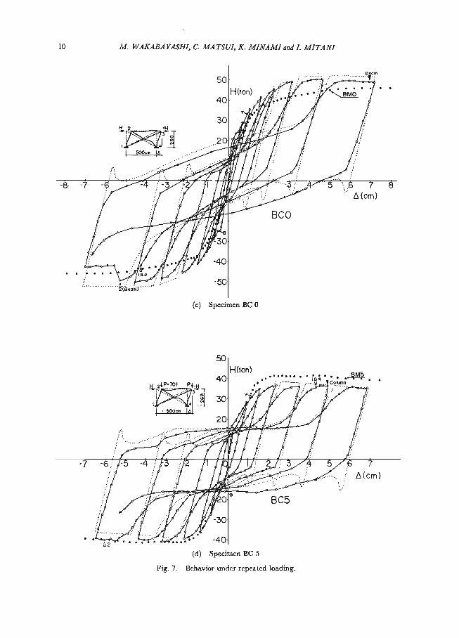
Horizontal load-horizontal displacement relationships obtained from the four tests under monotonic loading are shown in Fig. 6, and those under repeated loading in Fig. 7. In these figures, the ordinate corresponds to the horizontal loads (H) and the abscissa corresponds to the horizontal displacements measured at the column tops (a). The occurrence of buckling of the compression bracings (B), local buckl-ing of the flange plates (v ), and lateral buckling of beam or column (V), all of which were visually observed, are indicated in Figs. 6 and 7. Also indicated in the figure is the incipience of the yeilding of the tension bracing (Y) as was observed through the strain measurements.
Stated below are the frame behaviors as indicated by the experiments.
H (ton )
50 BMO
.•""8M5iPIP Hila
30 Y 40..lasegallegligin.4 • Boom -o-e-'ExPernefit01
TheOretiCal B Buckling of Brace ._ rn A
Y Yielding of Brace
20 . . Local Buckling FMOoCtoumn13- 4) y.Lateral Buckling
10 Y2v3•crn otunE3-4) la
as 0 1 2 3 4 5 6 , 7 8 9 10 11 12 13 14 15 4 (
cm)
Fig. 6. Behavior under monotonic loading

Inelastic Behavior of Full-Scale Steel Frames with and without Bracings 9
a. Unbraced Frames
a.! Monotonic Loading
It was apparent that the vertical load greatly affected the shape of the horizontal load-displacement relationship. The test frame FM 0 (without vertical load) sustained more load after the strain hardening phenomenon took place, and showed stable behavior, while the test frame FM 5 (with vertical load) showed deterioration in sustaining the horizontal load after the frame had fully yielded due to the overturn-ing moment, and the load-displacement behavior was found to be unstable.
a.2 Repeated Loading
Test frame FC 0 (without vertical load) showed stable behavior in every cycle of repeated loading. As the number of loading cycles increased, the load-displacement
--- ExP"I"L"T"Ht ..- 20H(ton)---•.. THEORETICAL"123 • • .f/eN010„tcF f
V LOCAL BUCKLING I'4 LATERAL BucKuNG 4""' 16:..6901.11-erti . . . . • , .
,
../
. . - .
. . . ,
..8 9 ••-.'"(cm)
FCC, .• . .
. . .
i2IBILOIR/-. -2* Aseam
Fig. 7. (a) Specimen FC 0
2. H(ton)
it ,P-701 13 i:.0
" • • V2
. — i . • . ..
. . • ". . • . . .
- - • - 5,,,47-3 - 2 .), I .0 pr . - • . : • ..,-.%. • A(cm)
. FC5 . . . • . . . . . • •
-20
(b). Specimen FC 5
10 M. WAKABAYASHI, C. MATSUI, K. MINAMI and L MITANI
Beam 50
H(ton).... . . ,1/4„, Bmo • • 40
30 /• 1-rFP'-'
•
-
. -. /11 _atoos‘er :: -8 -7 -, -A -3 7 -Pr..ir''...
.-i....-
_oldb ir BOO L (cm)
-
. .
. -
-50 (intom)'
(c) Specimen BC 0
50 H (ton)
40••.104a •• t.,2+ P:79, Fl:IL,
4 , 500a
'' .IS
. . • - :
. .
• . - - a
OM : •
. , .. .. 71-170 e BC5 . . . / . .Y. 30
L2
(d) Specimen BC 5
Fig. 7. Behavior under repeated loading.

Inelastic Behavior of Full-Scale Steel Frames with and without Bracings 11
relation reached a stable state. The hysteresis curve is expressed by the Masing model. Test frame FC 5 (with vertical load) showed instable behavior in every cycle of loading. The load carrying capacity was improved with the increasing number of loading cycles. This was due to, (1) residual P-a moment remaining in the frame when the horizontal load direction was reversed, and to, (2) increased moment re-sistance in the column cross section caused by strain hardening. Strain hardening
phenomenon was observed in the column section where the compressive strain was accumulated undergoing the repeated plastic bending moment under a constant ver-tical load. Figure 8 shows how the strain was accumulated in the column cross section. The hysteresis curve for the case is expressed by a negative bi-linear one which allows the horizontal load carrying capacity to increase in every cycle of loading.
11110=1.2 12 Illtoal
a
luRim 17.2— 11.202aMIA
4
=lilt NIBO EN-1.43.1310.4
P I1KiloPI 18.7.4 11-178 4 Pc5 I !I1k FOI5
(a)
HOW 12
a i2 .4 8
,L11.Po.1
4
F—I IC5
1 4
(b) Fig. 8. Accumulation of plastic strain.
b. Braced Frames
b.1 Monotonic Loading
Among the failures in the braced frame subjected to monotonic loading, the buckling of the compression bracing took place first, and the frame rigidity was decreased. However, the deterioration in horizontal-load carrying capacity did not occur. At this stage, the rigid frame members and the tension bracing were still in

12 M. WAKABAYASHI, C. MATSUI, K. MINAMI and L MITANI
the elastic range. Next was the yeilding of tension bracing, and the frame rigidity was drastically decreased, with the rigid frame members still in the elastic range and the horizontal-load still increasing. Then, yielding progressed through the frame members. Test frame BM 0 showed no deterioration in the horizontal-load carrying capacity because of the strain hardening induced in the frame component members. As for the test frame BM 5, similar to FM 5, instability was observed due to the ad-ditional over turning moment. The frame rigidity in this region was approximately equivalent to that found in the case of FM 0 frame. Braced frames, in general, were less affected by the instability phenomenon caused by the P— A effect than the unbraced counterparts, because the former had larger resistance against horizontal force provided by the bracing members than the latter had.
b.2 Repeated Loading
Hysteresis loops of the braced frames under repeatedly applied horizontal force were substantially different from those of the unbraced frames. This was because of the post buckling behavior of the compression bracing and the behavior of bent ten-sion bracing. Further, the configuration of the hysteresis loops was difficult to predict from that found in the monotonic loading case. It was less affected by the column vertical load, and the hysteresis loops for BC 0 and BC 5 were both reversed S shaped. The only slight differences observed between these two test frames was the behavior in the regions, i) where the sway was zero when both tension and compression bracings were relaxed, and, ii) where the sway was at its maximum when the both bracings were in the stable state. That is, in these regions, the behavior of the unbraced rigid frame was apparently reflected in that of the braced frame, and BC 5 showed less rigidity than BC 0 due to the effect of the vertical load.
The increase in the load carrying capacity with the increasing number of loading repetition, which was observed in FC 5, was not in the case for BC 5 which was loaded by the same magnitude of vertical load as FC 5. This was because of the fact that, in each cycle of loading, the horizontal displacement at the maximum load carrying capacity of the rigid frame did not coincide with that of the bracing.
Following are the common behaviors observed in the tests of both unbraced and braced frames.
In the load-displacement relationships, every test frame exhibited a decrease in rigidity in the earlier stage of loading program. This owed to the introduction of bending moment into the test frame during the process of fixing the test frame to the test bed. The magnitude of this introduced bending moment, as was estimated from the strain readings, at the column bottom were from 30 to 50% of the yield moment of the column cross section.
The restoring force of the entire frame did not deteriorate by the local buckling of the cross sectional component plate. Under repeated loading, however, lateral buckling took place due to the decrease in out-of-plane rigidity of the member cross section, which was further caused by the spread deformation in the local buckling
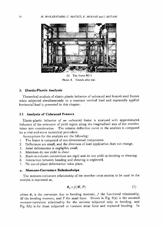
portion, hence the frame restoring force deteriorated (Photos. 6 and 7). At such a stage, difficulties appeared in the load application, and the testing was terminated for the test frames FC 5, BC 0 and BC 5. Test frames FC 5 and BC 5 after tests are shown in Photos. 8(a) and 8(b), respectively.

Inelastic BehaviorofFull-Scale Steel Frameswith and without Bracings13
. !III i r.ki *7 Artz !--;,,-.,,i;:",,
, ' _tioP iis...
I
Ilk ,,,. yi (-
r., ......._- ' I -f,t t. ,< ....‘' , '41. 44 ' 4 i: 4 '"? '. 4 1 Iii (
1(11"4le
'4444404,i-.4'''''..s'eI.*. k.,,,`...‘'rA,'.'It.1 I .' 4' ,' f, e 1/2r
t 4 :. 41 -4,1, , , 2.t., qz.-4., ,, ai , , 1 e '.' r", ,- , ,,•iorf', k of ' , s,i,, % ,:i f :="
lek I .,--,)4," g10,4 Ao _...t ki t
\ 'fr ad d , - ,4,Ha• 4k. * . , : \ - ' '' ... .
k alli Ell Pli k - " ' '
,;, Photo. 6. Local buckling (FC5)r •:':••"/ ' . ," • I '( —,i•
i, c,4' TM 1111 ‘ (- Photo. 7. Lateral buckling (FC 5)
man ,..,1 ' 1. ' Tigta-
iila lierrom ar. n.- .
t
iiiv i- , — 4.1 t.i .''---, -i. icli '
Li;etirC. l''' 1 i ri III ' 1:91- L Ft hL.,tkII ei+JO11,11_1.fF.F;!',-,..4 i—'--- F.
41k,
Photo. 8. (a) Test frame FC 5
14 M. WAKABAYASHI, C. MATSUI, K. MINAMI and I. MITANI
Y# , twi,,,,44,„„
ti i %lb SS r., ,'., IF • 1111 tic iti 'it, ., 7111111111r regret • I. it ,1
I
Sis.
1
! ::!-1 _ _ * r ItsiiN -
, i 1 4 '',1''-, 1 -,44:1 ll li I - .. --"triar Sr Mi > , 1.k.,:;-ti , 4' g , • — - t — er ' - --. _ ' -.^,- I—L-1_ _Ls. _._
(b) Test frame BC 5 Photo. 8. Frames after test.
3. Elastic-Plastic Analysis
Theoretical analysis of elastic-plastic behavior of unbraced and braced steel frames when subjected simultaneously to a constant vertical load and repeatedly applied horizontal load is presented in this chapter.
3.1 Analysis of Unbraced Frames
Elastic-plastic behavior of an unbraced frame is analysed with approximated influence of the extension of yield region along the longitudianl axis of the member taken into consideration. The column deflection curve in the analysis is computed by a trial-and-error numerical procedure.
Assumptions for the analysis are the following: 1. The frame is composed of one-dimensional components. 2. Deflections are small, and the direction of load application does not change. 3. Axial deformation is negligibly small. 4. Members do not yield in shear. 5. Beam-to-column connections are rigid and do not yield in bending or shearing. 6. Interaction between bending and shearing is neglected. 7. No out-of-plane deformation takes place.
a. Moment-Curvature Relatinohsips
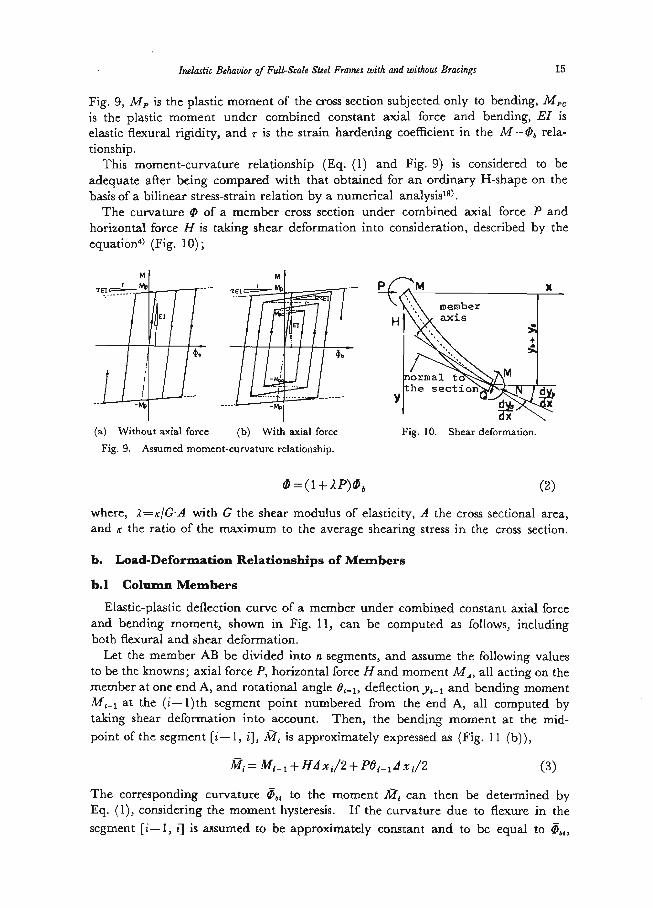
The moment-curvature relationship of the member cross section to be used in the analysis is expressed as,
(D b= f(M,P) (1)
where 0, is the curvature due to bending moment, f the functional relationship, M the bending moment, and P the axial force. Shown in Fig. 9(a) is the assumed moment-curvature relationship for the sections subjected only to bending, and Fig. 9(b) is for those subjected to constant axial force and repeated bending. In
Inelastic Behavior of Full-Scale Steel Frames with and without Bracings 15
Fig. 9, Ai, is the plastic moment of the cross section subjected only to bending, M„ is the plastic moment under combined constant axial force and bending, El is elastic flexural rigidity, and r is the strain hardening coefficient in the M-0, rela-tionship. This moment-curvature relationship (Eq. (I) and Fig. 9) is considered to be
adequate after being compared with that obtained for an ordinary H-shape on the basis of a bilinear stress-strain relation by a numerical analysis").
The curvature 0 of a member cross section under combined axial force P and horizontal force H is taking shear deformation into consideration, described by the
equation (Fig. 10);
REIN___TE/ X ------ 111 member
1111Haxis YkM he ee sctio noNIF d
-Pro •x di
(a) Without axial force (b) With axial force Fig. 10. Shear deformation. Fig. 9. Assumed moment-curvature relationship.
0 = (1+ 2P)0b (2)
where, A=KIG-A with G the shear modulus of elasticity, A the cross sectional area, and K the ratio of the maximum to the average shearing stress in the cross section.
b. Load-Deformation Relationships of Members
b.1 Column Members
Elastic-plastic deflection curve of a member under combined constant axial force and bending moment, shown in Fig. 11, can be computed as follows, including both flexural and shear deformation.
Let the member AB be divided into n segments, and assume the following values to be the knowns; axial force P, horizontal force Hand moment MA, all acting on the member at one end A, and rotational angle deflection and bending moment
M5_1 at the (i-1)th segment point numbered from the end A, all computed by taking shear deformation into account. Then, the bending moment at the mid-
point of the segment [i-1, M, is approximately expressed as (Fig. 11 (b)),
Mi_1+1141 xd2+ POi_it x i/2 (3)
The corresponding curvature 0„, to the moment M, can then be determined by Eq. (1), considering the moment hysteresis. If the curvature due to flexure in the segment [i-1, i] is assumed to be approximately constant and to be equal to ()„„

16 M. WAKABAYASHI, C. MATSUI, K . MINAMI and I. MITAN1
p MA WSWIVe, H 8.1111111
LH Meer-
YL
e„ -MU At An GI
y
Fig. II. Column subjected to end force.
the curvature in this segment with shear deformation taken into account can then be determined by Eq. (2), and the rotational angle O„ the deflection y„ and the moment M, can be obtained as,
Oi=t2i-i+Ci(1+ AP)z xt (4)
yi=x• Yz-i+2 (0i-i +0i) (5)
Mt= MA±H•xi+ P. yi (6)
where, zlx, is the length of the segment Li-1, i], and x, the distance of the segment
point i from the end A. If the above explained computation proceeds for each segment to the other end B in a similar manner, a deflection curve of the member AB can be obtained.
Next, the initial values of the rotational angle Oo and the deflection yo at the end A are computed. Let the joint rotation angle be 0, and the shear deformation angle at the member end adjacent to the joint be Os, then (Figs. 10 and 12),
A •
Fig. 12. Column deformation.
00=0,1+0,=(1-1-1P)0A+ AH (7)
and the initial deflection at the end A is

Inelastic Behavior of Full-Scale Steel Frames With and without Bracings 17
ye=a0A (8)
where a is the length of the rigid region.
b.2 Beam Members
If a beam is subjected to external load as shown in Fig. 13, shear force is constant
MA
Fig. 13. Beam subjected to end moment.
along the member length, and the curvature due to shear is zero. Therefore, only bending is considered when computing the angle of deflection slope. The cross section rotates by an uniform angle Be, so the rotational angle of the cross section at the member end A, Od can be expressed as,
OA=Oe+0, (9)
in which Oh is the angle caused by bending. And,
Os= AMA/I (10)
Therefore, if the end moment M, and the angle 0, are given, MA-0„ relationship, with shear deformation taken into account, can be obtained.
When a simply supported beam with the span length 1 is subjected to an end moment MA, as shown in Fig. 13, curvature distribution along the beam length is determined
by Eq. (1) taking the moment hysteresis into account, and the angle /9„ is obtained as,
05=5of(MA)x/1 dx (11) Considering the rigid region, the angle 0„ can be expressed as (see Fig. 14),
OA=(1— 1 )(0e+0,) (12)
C MA AIK-Crb Fig. 14. Beam deformation.

18 M. WAKABAYASNI, C. MATSUI, K. MINAMI and I. MITANI
c. Load-Deformation Relationship of a Frame
With the results described in the preceding articles. The load-deformation rela-tionship of a steel portal frame of the kind adopted in the experimental study will be obtained in this article.
The frame shown in Fig. 15 (a) can be replaced, without loosing any generality, by the one shown in Fig. 15 (b), since the anti-symmetricity of deformation is found in the frame, if change in column axial force due to beam shear is neglected. There- fore, the analysis in this article is proceeded on the simplified, knee-shaped frame.
The deformation mechanism of sucha frame under constant vertical load and horizontal load is like the one shown inFig. 15 (c).The moment-rotation relation is, in general terms, as the following, utilizing the result of the preceding aritcle.
•
2_..H 1p/13 o=-mar- ar B • 1111es war Met
,l/2
1.c
A
2
Ma IA I
A
(a) (b)(c) Fig. 15. Model frame.
08=f I (Mac) (13)
Equilibriums of joint moments and column shear give,
MBA+ MBC 0 (14)
MAB+ .1148A=Hh+PA (15)
Load-deflection relationship of the column, in general, is obtained from the perced-ing article, and is expressed as,
OA= f2(MBA, P, H2OB)= AH (16)
A =fs(Maa, P, H, On) (17)
Since there are five equations, Eqs. (13)—(17), and six unknowns, MAR, MBA, H, BB, and 4, this set of equations can be solved by a trial-and-error technique if one
of the six unknowns is assumed. The anlysis is carried out by the following procedure.
I. With the assumed value of Mao, BB and Ms, are determined, respectively, from Eq. (13) and Eq. (14)
2. H is computed, by trial-and-error technique, from Eq. (16). Using the value

Inelastic Behavior of Full-Scale Steel Frames with and without Bracing, 19
of H thus obtained, A and Ms are calculated by Eqs. (17) and (15), respectively. 3. Using the increasing or decreasing values of M, corresponding, respectively,
to the loading or unloading of horizontal force, the horizontal load-deformation relationship of a frame under repeated loading can be computed by the steps
I. and 2. In the numerical analysis of test frames, the beam-to-column connection was
considered to form one segment, and a column member was divided into 24 segments. In the analysis, r was taken to be 0.01.
3.2 Analysis of Braced Frames
Horizontal load-horizontal displacement relationship of a braced frame is obtained by summing up the horizontal force of an unbraced frame and of bracing system corresponding to the same magnitude of horizontal displacement, as illustrated in Fig. 16. Elastic-plastic analyses were separately made on the unbraced frame and on the bracing system, both on the concept of the plastic hinge method.
H. ‘P IP IP IP
11011101-4111111111IN Fig. 16. Concept of braced frame analysis
a. Analysis of Bracing System
The bracing system is analysed by taking into account the axial displacement of a bracing at the plastic hinge, which is due to axial force and bending. The analysis makes use of the plastic flow rule and is based upon the plastic hinge method16),19). The effective length of a bracing used in the analysis is equal to L/2, with L being the length of a bracing shown in Fig. 1 (b). This length was chosen on the basis of experimentally observed deformation behavior of bracing members. An example of the analytical results is illustrated in Fig. 17.
TENS. Ny
;:1:11)LOAD OF A BRACING NyN:
a
NCR : BUCKL ENG LOAD OF A BRACT N6iladild _Sar canna
at
cow.
Fig. 17. Theoretical behavior of a brace.

20 M. WAKABAYASHI, C. MATSUI, K. MINAMI and L MITANI
b. Analysis of Frame
Analysis of an unbraced rigid frame can be done by a rigorous numerical procedure described in 3.1. However, in this article, the analysis of the unbraced frame is made on the basis of the plastic hinge method, since the bracing system is analysed by it, as was described above. The slope deflection method that takes into account the exstence of axial force is used for the analysis.
Beside the assumptions 1., 2. and 3. introduced in 3.1, additional ones are made; 8. Axial deformation and shear deformation of the frame members are neglected. 9. Yielding due to flexure does not take place in the beam-to-column junctures
and in the portions where gusset plates are welded. 10. Yield criterion for the cross section is given by,
MALT.= 1.18Mp(1 — —) and Mpc 11113 (18) II. Additional axial force caused in the column by the bracing axial force is
inculded in P appearing in Eq. (18) in addition to the constantly applied included in P appearing in Eq. (18) in addition to the constantly applied vertical load. This additional axial force is computed assuming that axial force-axial
deformation relationship of a bracing is such a one as shown in Fig. 18. This relationship is a simplification of the analytical results shown in Fig. 17.
Ny i
THEORETI CAL
\S- ASSUMED 7.7
Elala1111W. at
Fig. 18. Assumed axial force of a bracing for calculating axial force of a frame member.
4. Comparison of Experimental Behavior with Theoretical Results
In Figs. 6 and 7, shown in dotted lines are the theoretically obtained behavior of
each test frame. Black spots in Fig. 7 are to show, for comparison, the frame bahevior

Inelastic Behavior of Full-Scale Steel Frames with and without Bracing' 21
under monotonic loading. In Figs. 7 (c) and 7 (d), the first several loading cycles of theoretical results are not plotted, since they almost coincide with each other and disturb the lines experimentally obtained.
4.1 Unbraced Frames
In the stage of initial loading, the decrease in the rigidity took place earlier in the experimental results than in the theoretical prediction. This was, as stated before in 2.5, due to the bending moment induced in the members prior to the application of the horizontal load. Besides the disagreement in this region, the theoretical
prediction well represented the experimental behavior of both test frames FM 0 and FM 5. As for the frames tested under repeated loading, the theoretically predicted behavior well traced the experimentally obtained characteristics. It is proved by this comparison that the moment-curvature relationships assumed in the analysis were adequate ones.
4.2 Braced Frames
In the case of monotonic loading, buckling of the bracing took place at a considerab-ly earlier stage than that theoretically predicted. It was found, judging from the the strain readings on the bracing members, that compression force was introduced in the bracing when the test frame was fixed to the test bed. The magnitude of the initially induced compression in the bracing was between 10 to 20% of the yield load of the cross section.
This initial compressive force was taken into consideration in the analysis. How-ever, the earlier buckling behavior of these test frames could not be fully explained by that. Further considerations on the point revealed the following possible reasons; that is, (1) existence of residual stresses in bracings (2) initial curvature of bracing, and (3) introduction of unexpected bending moment into the bracing caused by the
possible rotation of beam-to-column connections and column bases. These reasons were found to be acceptable on the basis that no drastic decrease was indicated in the experimentally obtained load carrying capacity when the buckling of bracing members took place. After the buckling of bracing and until the frame had fully yielded, the experimental results showed a lower rigidity than the theoretical prediction, as was the case of the test frames FM 0 and FM 5. To improve the prediction of the frame behavior in this region, more detailed experimental conditions must be included in the analysis.
In the case of repeated loading, the most notable discrepancy between the experi-mental behavior and the theoretical prediction lay in the fact that, in every cycle of loading, drastic deterioration in the horizontal load carrying capacity was predict-ed by the analysis after the buckling of compression bracing. This can be explained as follows. In the analysis, the stress-strain relation of the material was assumed to be of elastic-perfectly plastic type. Therefore, under repeated axial displacement, the bracing stretched straight when sujected to tension and buckled after compression was loaded (see Fig. 17). In the actual bracing, however, due to strain-hardening
phenomenon, the bracing was never stretched straight even when the load applica-tion was reversed and the bracing had an initially bent configuration when the load

22 M. WAKABAYASIII, C. MATSUI, K. MINAMI and I. MITANI
was reversed from tension to compression. Furthermore, as was referred to earlier in this article, bending moment tha was associated with the joint rotation was in-troduced into the bracing. With these considerations it was concluded that drastic deterioration in the load carrying capacity of the braced frames was not found in their experimental behavior.
Except in the region where buckling of bracings occurred, the analysis well predict-ed the experimental behavior of braced frames. It was proved, therefore, that the theoretical analysis presented in this paper, which was the summation of the restoring force characteristics of the two different structural systems, was practical and rea-sonable.
5. Conclusions
The following are the conclusions from the experimental and theoretical investiga-tions into the behavior of both unbraced and braced steel frames that are subjected simultaneously to constant vertical load and monotonic or repeated horizontal load. 1. The existence of vertical load greatly affected the shape of hysteresis loops of
unbraced frames; without vertical load, the shape was of the Masing type, and with a large vertical load, the maximum horizontal load was raised from cycle
to cycle and the loop never closed (negative bi-linear). 2. The hysteresis loops of the braced frames were reversed S shaped, and hardly
affected by the veritcal load. 3. Load carrying capacity of unbraced frames under combined constant vertical
load and repeated horizontal load was increased in every loading cycle. This was when in the column cross section extensive yielding occurred and was due to
the strain-hardening phenomenon caused by the accumulated compressive strain in the section. In the case of braced frames, as well as unbraced frames without
vertical load, such a phenomenon was not observed. 4. Local buckling alone did not disturb the stability of restoring force characteristics.
Under repeated horizontal load, however, lateral buckling was induced, due to the decrease in rigidity caused by excess deformation in the locally buckled
portion, and the resulting restoring force charcteristics showed deterioration. 5. Experimental behavior of unbraced frames was well predicted by the theoretical
analysis described in this paper when the moment-curvautre relationship present- ed in Fig.9 was utilized.
6. Experimental behavior of braced frames can be adequately predicted by the theoretical assessment that combined the load-displacement relationship of unbraced frame with that of bracing system, both of which were obtained on
the basis of the plastic hinge method.
References
I) Wakabayashi, M.: "The Restoring Force Characteristics of Multi-Story Frames", Bull. of Disaster Prevention Research Institute, Kyoto Univ., Vol. 14, Part 2, No. 78, Feb. 1965,
pp. 29-47. 2) Arnold, P., P. F. Adams and L. W. Lu: "Experimental and Analytical Behavior of a Hybrid
Frame", Fritz Engrg. Lab. Report 297.18, Lehigh Univ., May 1966. 3) Wakabayashi, M., T. Nonaka and C. Matsui: "An Experimental Study on the Inelastic
Inelastic Behavior of Full-Seale Steel Frames with and without Beatings 23
Behavior of Steel Frames Subjected to Vertical and Horizontal Loading", Bull. of Disaster Prevention Res. Inst., Kyoto Univ., Vol. 17, Part I, No. 119, July 1967, pp. 27-48.
4) Wakabayashi, M., T. Nonaka and C. Matsui: "An Experimental Study on the Horizontal Restoring Forces in Steel Frames under Large Vertical Load", Proc. of 4th world Conf. on
Earthquake Engrg., Santiago, Chile, Vol. I B-2, Jan. 1969, pp. 177-193. 5) Wakabayashi, M., T. Nonaka and S. Morino: "An Experimental Study on the Inelastic
Behavior of Steel Frames with a Rectangular Cross-Section Subjected to Vertical and Hori- zontal Loading", Bull. of Disaster Prevention Res. Inst., Kyoto Univ., Vol. 18, Part. 3, No.
145, Feb. 1969, pp. 65-82. 6) Wakabayashi, M. and C. Matsui: "Experimental Studies on the Elastic-Plastic Stability of
Steel Frames, (Part I) Portal Frames with Rectangular Cross Sections", Trans. of Arch. Inst. of Japan, No. 192, Feb. 1972, pp. 11-22 (in Japanese).
7) Wakabayashi, M. and C. Matsui: "Experimental Studies on the Elastic-Plastic Stability of Steel Frames, (Part 2) Portal Frames with Wide Flange Sections", Trans. of Arch. Inst. of Japan, No. 193, March 1972, pp. 17-27 (in Japanese).
8) Wakabayashi, M., C. Matsui and I. Mitani: "Experimental Studies on the Elastic-Plastic Stability of Steel Frames, (Part 3) Cruciform Frames with Wide Flange Sections", Trans. of
Arch. Inst. of Japan, No. 194, April 1972, pp. 9-19 (in Japanese). 9) Arnold, P., P. F. Adams and L. W. Lu: The Effect of the Instability on the Cyclic Behavior
of a Frame", Fritz Engrg. Lab. Report 297.24, Lehigh Univ., Sept. 1966. 10) Igarashi, S., N. Taga, S. Takada and Y. Koyanagi: "Plastic Behavior of Steel Frames under
Cyclic Loadings", Trans. of Arch. Inst. of Japan, No. 130, Dec. 1966, pp. 8-15. I I) Fujimoto, M., H. Hakura and Y. Matsumoto: "Experimental Study on Inelastic Behavior
of Steel Structures under Repeated Loading", Proc. of Annual Meeting of Arch. Inst. of Japan, Oct. 1968, pp. 931-932 (in Japanese).
12) Carpenter, L. D. and L. W. Lu: "Repeated and Reversed Load Tests on Full Scale Steel Frames", Proc. of 4th World Conf. on Earthquake Engrg,. Santiago, Chile, Vol. I, B-2, Jan. 1969, pp. 125-136.
13) Wakabayashi, M., C. Matsui and I. Mitani: "Experimental Studies on the Elastic-Plastic Stability of Steel Frames, (Part 4) Subassemblages with Wide Flange Sections Subjected to
Alternating Horizontal Force", Trans. of Arch. Inst. of Japan, No. 195, May 1972, pp. 25-37 (in Japanese).
14) Wakabayashi, M. and B. Tsuji: "Experimental Investigation on the Behavior of Frames with and without Bracing under Horizontal Loading", Bull, of Disaster Prevention Res. Inst.,
Kyoto Univ., Vol. 16, Part 2, No. 112, Jan. 1967, pp. 81-94. 15) Wakabayashi, M., C. Matsui, K. Minami and I. Mitani: "Inelastic Behavior of Full Scale
Steel Frames", Annual, Disaster Prevention Res. Inst., Kyoto Univ., No. I3A, March 1970, pp. 329-363 (in Japanese).
16) Wakabayashi, M.: "The Behavior of Steel Frames with Diagonal Bracings under Repeated Loading", Proc. of U. S.-Japan Seminar on Earthquake Engrg. with Emphasis on the Safety
of School Buildings, Sendai, Japan, 1970, pp. 328-359. 17) Fujimoto, M., T. Aoyagi, K. Ukai, A. Wada and K. Saito: "Structural Characteristics of
Eccentric K-Braced Frames", Trans. of Arch. Inst. of Japan, No. 195, May 1972. pp. 39-49 (in Japanese).
18) Igarashi, S., C. Matsui, K. Yoshimura and K. Matsumura: "Inelastic Behaviors of Struc- tural Sections under Alternative Loading" (1) Method of Analysis and Examples, Trans. of
Arch. Inst. of Japan, No. 169, March 1970, pp. 53-62, (2) Final State of Resisting Moment and Experimental Study, Trans. of Arch. Inst. of Japan, No. 170, April 1970, pp. 39-50.
19) Nonaka, T.: "An Elastic-Plastic Analysis of a Bar under Repeated Axial Loading", Int. Jour. of Solids and Structures, Vol. 9, No. 5, May 1973, pp. 569-580; with erratum in Vol. 9,
No. 10, October 1973.