Titan gas turbinegasturbine Air start engine - JET- · PDF fileaxial flow turbine stage. The...
86
Phone Fax Email (int +31) 492-545801 (int +31) 492-550379 [email protected] Heistraat 89 Helmond 5701 HJ copyright Titan gas turbine Titan gas turbine © Serial number Manual & ENGINE LOG ( V20 B) & ENGINE LOG ( V20 B) NL Air start engine Electric start engine
Transcript of Titan gas turbinegasturbine Air start engine - JET- · PDF fileaxial flow turbine stage. The...
PhoneFaxEmail
(int +31) 492-545801(int +31) [email protected]
Heistraat 89Helmond5701 HJ
copyright
Titan gas turbineTitan gas turbine
©
Serial number
Manual & ENGINE LOG ( V20 B)& ENGINE LOG ( V20 B)
N L
Air start engine
Electric start engine

Copyright 2009 by B.J.J. van de Goor AMT Netherlands all rights reserved. This manual may not be reproduced, in whole or in part, by photocopy or print or any other means, without permission from the publisher. Write for information to: AMT Netherlands b.v. Heistaat 89 5701 HJ Helmond the Netherlands Webside : Http:// www.amtjets.com E-mail : [email protected]
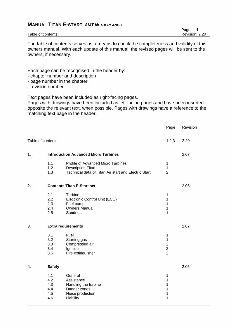
MANUAL TITAN E-START AMT NETHERLANDS Page :1 Table of contents Revision: 2.20
The table of contents serves as a means to check the completeness and validity of this owners manual. With each update of this manual, the revised pages will be sent to the owners, if necessary. Each page can be recognised in the header by: - chapter number and description - page number in the chapter - revision number Text pages have been included as right-facing pages. Pages with drawings have been included as left-facing pages and have been inserted opposite the relevant text, when possible. Pages with drawings have a reference to the matching text page in the header. Page Revision Table of contents 1,2,3 2.20 1. Introduction Advanced Micro Turbines 2.07 1.1 Profile of Advanced Micro Turbines 1 1.2 Description Titan 1 1.3 Technical data of Titan Air start and Electric Start 2 2. Contents Titan E-Start set 2.05 2.1 Turbine 1 2.2 Electronic Control Unit (ECU) 1 2.3 Fuel pump 1 2.4 Owners Manual 1 2.5 Sundries 1 3. Extra requirements 2.07 3.1 Fuel 1 3.2 Starting gas 1 3.3 Compressed air 2 3.4 Ignition 2 3.5 Fire extinguisher 2 4. Safety 2.05 4.1 General 1 4.2 Assistance 1 4.3 Handling the turbine 1 4.4 Danger zones 1 4.5 Noise production 1 4.6 Liability 1

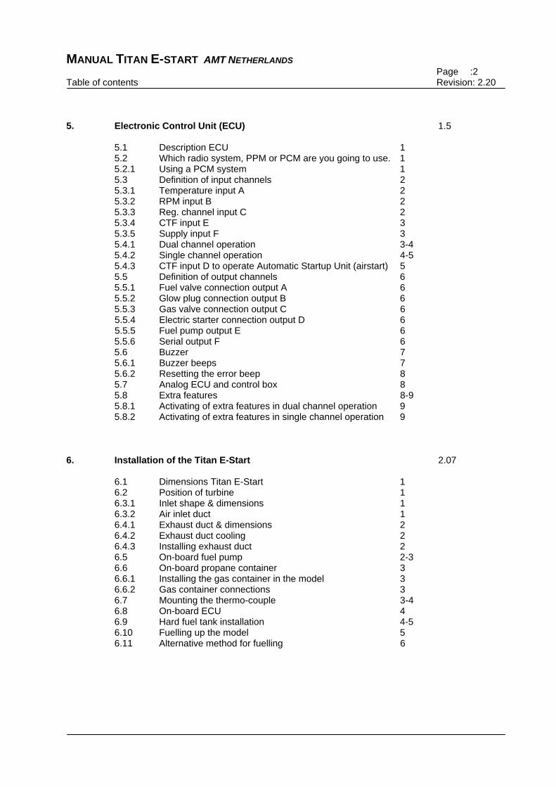
MANUAL TITAN E-START AMT NETHERLANDS Page :2 Table of contents Revision: 2.20
5. Electronic Control Unit (ECU) 1.5 5.1 Description ECU 1 5.2 Which radio system, PPM or PCM are you going to use. 1 5.2.1 Using a PCM system 1 5.3 Definition of input channels 2 5.3.1 Temperature input A 2 5.3.2 RPM input B 2 5.3.3 Reg. channel input C 2 5.3.4 CTF input E 3 5.3.5 Supply input F 3 5.4.1 Dual channel operation 3-4 5.4.2 Single channel operation 4-5 5.4.3 CTF input D to operate Automatic Startup Unit (airstart) 5 5.5 Definition of output channels 6 5.5.1 Fuel valve connection output A 6 5.5.2 Glow plug connection output B 6 5.5.3 Gas valve connection output C 6
5.5.4 Electric starter connection output D 6 5.5.5 Fuel pump output E 6
5.5.6 Serial output F 6 5.6 Buzzer 7 5.6.1 Buzzer beeps 7 5.6.2 Resetting the error beep 8 5.7 Analog ECU and control box 8 5.8 Extra features 8-9 5.8.1 Activating of extra features in dual channel operation 9 5.8.2 Activating of extra features in single channel operation 9 6. Installation of the Titan E-Start 2.07 6.1 Dimensions Titan E-Start 1 6.2 Position of turbine 1 6.3.1 Inlet shape & dimensions 1 6.3.2 Air inlet duct 1 6.4.1 Exhaust duct & dimensions 2 6.4.2 Exhaust duct cooling 2 6.4.3 Installing exhaust duct 2 6.5 On-board fuel pump 2-3 6.6 On-board propane container 3 6.6.1 Installing the gas container in the model 3 6.6.2 Gas container connections 3 6.7 Mounting the thermo-couple 3-4 6.8 On-board ECU 4 6.9 Hard fuel tank installation 4-5 6.10 Fuelling up the model 5 6.11 Alternative method for fuelling 6

MANUAL TITAN E-START AMT NETHERLANDS Page :3 Table of contents Revision: 2.20
7. Operation 2.08 7.1 Fuelling up the model 1 7.1.1 Fuelling the kerosine 1 7.1.2 Fuelling the propane 1 7.2 Powering up the system 2 7.3 Starting the Titan E-Start 2-3 7.4.1 Stopping the engine 3-4 7.4.2 Switching off in case of an emergency 4 7.5 Recommended refuelling/charging sequence 4 8. Maintenance 2.09 8.1 Preventive maintenance 1 8.1.1 Visual inspection of turbine and gear 1 8.1.2 Checking of bearings 1 8.2 Storage and Lubrication 2 8.3 Removal of front cap and prelubrication procedure 2 8.4 Returning motor for service or repair 3 8.5 P2 Pressure fitting installation 3 8.6 Looking after your gasturbine 4 9. Log Titan E-Start 2.05 9.1 How to complete the log 1 9.2 Log 1 10. Warranty conditions 2.04 10.1 Warranty conditions 1 10.2 Completing the Warranty card 1 10.3 Warranty 1 11. Engine Data Terminal 1.2 11.1 Description Engine Data Terminal 1 11.2 On Off switching 1 11.3 Charging the EDT 1 11.4 Startup screen 1 11.5 Screen 1 2 11.6 Screen 2 2 11.7 Screen 3 2 11.8 Additional Text 2,3 11.9 Error messages 3,4 Engine log 2.05

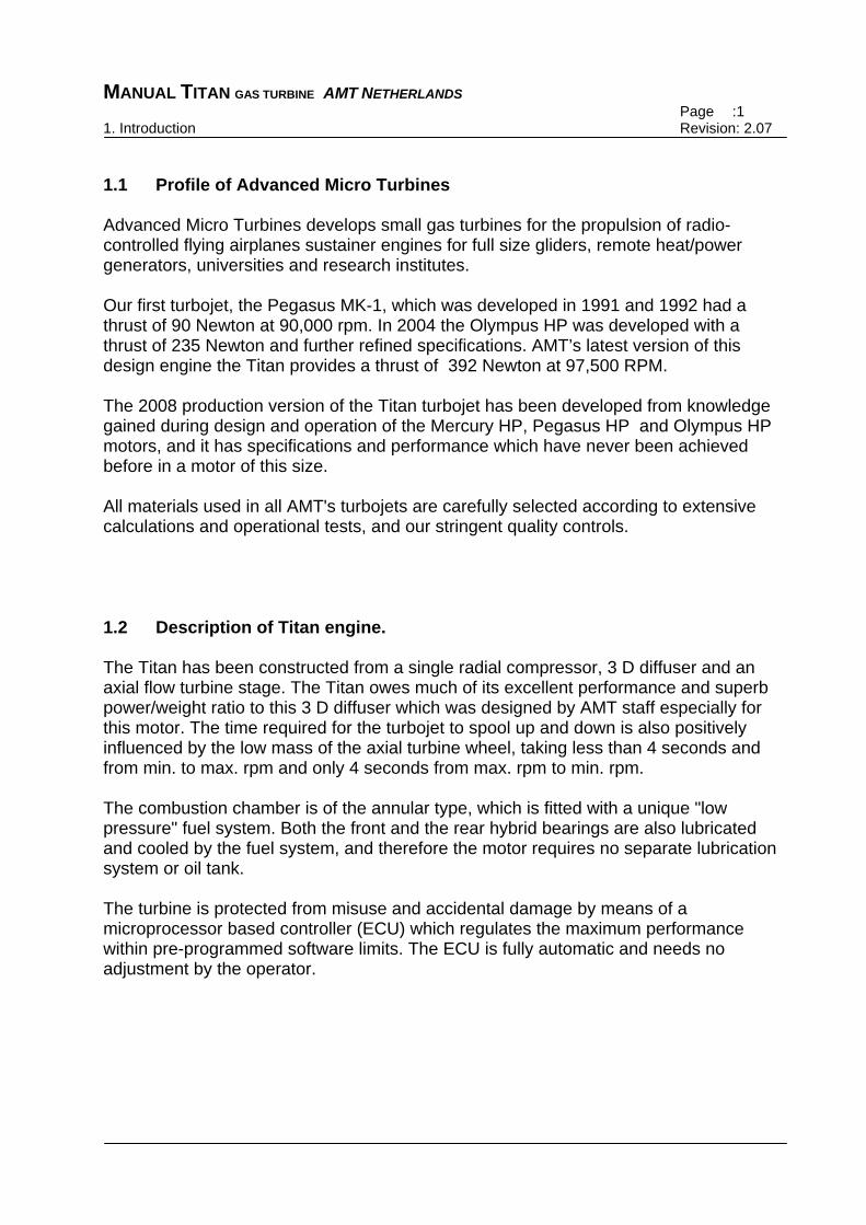
MANUAL TITAN GAS TURBINE AMT NETHERLANDS Page :1 1. Introduction Revision: 2.07
1.1 Profile of Advanced Micro Turbines Advanced Micro Turbines develops small gas turbines for the propulsion of radio-controlled flying airplanes sustainer engines for full size gliders, remote heat/power generators, universities and research institutes. Our first turbojet, the Pegasus MK-1, which was developed in 1991 and 1992 had a thrust of 90 Newton at 90,000 rpm. In 2004 the Olympus HP was developed with a thrust of 235 Newton and further refined specifications. AMT’s latest version of this design engine the Titan provides a thrust of 392 Newton at 97,500 RPM. The 2008 production version of the Titan turbojet has been developed from knowledge gained during design and operation of the Mercury HP, Pegasus HP and Olympus HP motors, and it has specifications and performance which have never been achieved before in a motor of this size. All materials used in all AMT's turbojets are carefully selected according to extensive calculations and operational tests, and our stringent quality controls. 1.2 Description of Titan engine. The Titan has been constructed from a single radial compressor, 3 D diffuser and an axial flow turbine stage. The Titan owes much of its excellent performance and superb power/weight ratio to this 3 D diffuser which was designed by AMT staff especially for this motor. The time required for the turbojet to spool up and down is also positively influenced by the low mass of the axial turbine wheel, taking less than 4 seconds and from min. to max. rpm and only 4 seconds from max. rpm to min. rpm. The combustion chamber is of the annular type, which is fitted with a unique "low pressure" fuel system. Both the front and the rear hybrid bearings are also lubricated and cooled by the fuel system, and therefore the motor requires no separate lubrication system or oil tank. The turbine is protected from misuse and accidental damage by means of a microprocessor based controller (ECU) which regulates the maximum performance within pre-programmed software limits. The ECU is fully automatic and needs no adjustment by the operator.
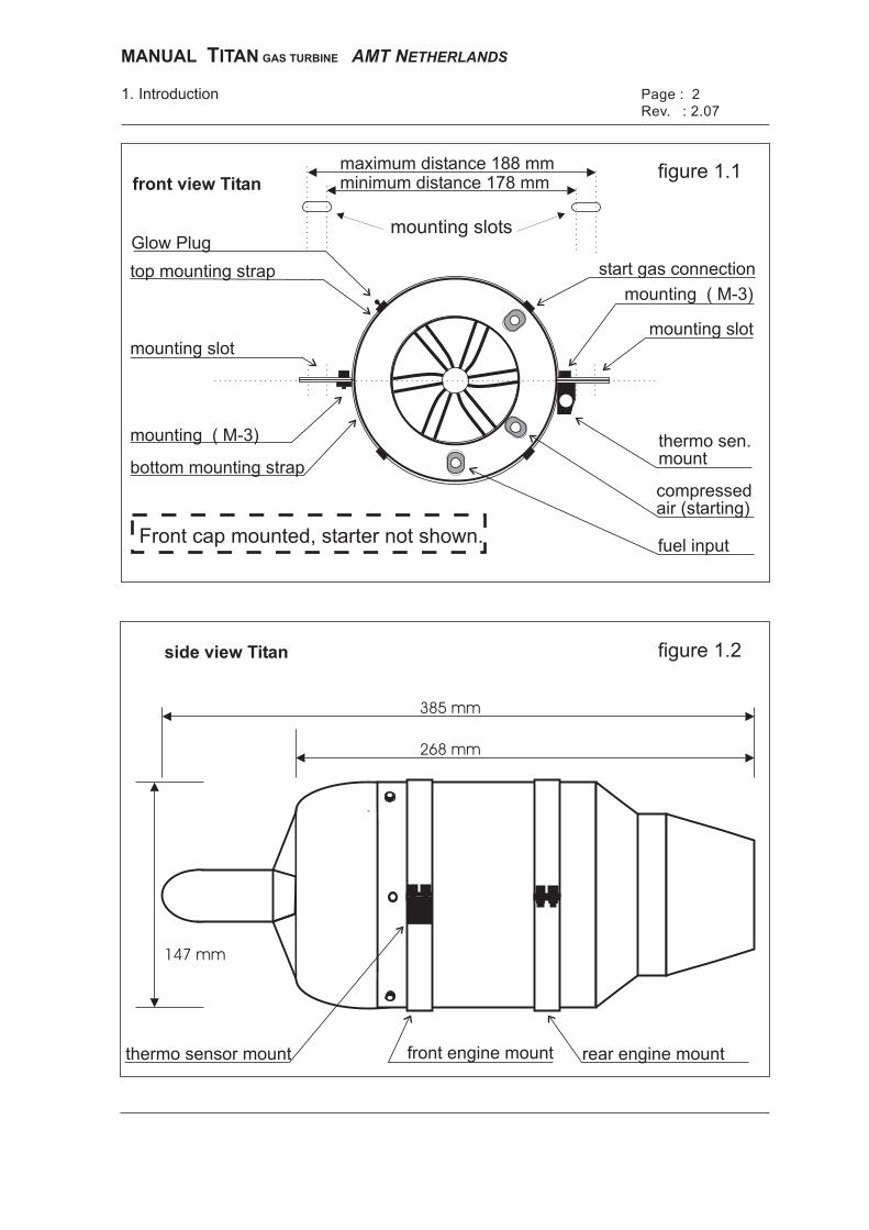
maximum distance 188 mmminimum distance 178 mmfront view Titan
figure 1.1
figure 1.2
©
1. Introduction Page : 2
Rev. : 2.07
mounting slots
MANUAL ITANT GAS TURBINE AMT NETHERLANDS
compressedair (starting)
fuel input
start gas connection
mounting ( M-3)
top mounting strap
Glow Plug
bottom mounting strap
mounting slotmounting slot
mounting ( M-3)
thermo sen.mount
Front cap mounted, starter not shown.
rear engine mountfront engine mountthermo sensor mount
385 mm
268 mm
147 mm
side view Titan
MANUAL TITAN GAS TURBINE AMT NETHERLANDS Page :2 1. Introduction Revision: 2.07
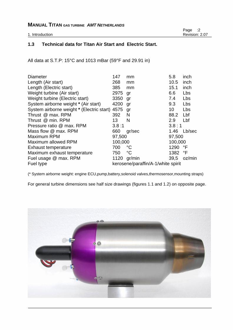
1.3 Technical data for Titan Air Start and Electric Start. All data at S.T.P: 15°C and 1013 mBar (59°F and 29.91 in) Diameter 147 mm 5.8 inch Length (Air start) 268 mm 10.5 inch Length (Electric start) 385 mm 15.1 inch Weight turbine (Air start) 2975 gr 6.6 Lbs Weight turbine (Electric start) 3350 gr 7.4 Lbs System airborne weight * (Air start) 4200 gr 9.3 Lbs System airborne weight * (Electric start) 4575 gr 10 Lbs Thrust @ max. RPM 392 N 88.2 Lbf Thrust @ min. RPM 13 N 2.9 Lbf Pressure ratio @ max. RPM 3.8 :1 3.8 : 1 Mass flow @ max. RPM 660 gr/sec 1.46 Lb/sec Maximum RPM 97,500 97,500 Maximum allowed RPM 100,000 100,000 Exhaust temperature 700 °C 1290 °F Maximum exhaust temperature 750 °C 1382 °F Fuel usage @ max. RPM 1120 gr/min 39,5 oz/min Fuel type kerosene/paraffin/A-1/white spirit (* System airborne weight: engine ECU,pump,battery,solenoid valves,thermosensor,mounting straps) For general turbine dimensions see half size drawings (figures 1.1 and 1.2) on opposite page.
Page : 1
Rev. : 2.05
2. Contents
MANUAL ITANT GAS TURBINE AMT NETHERLANDS
MANUAL TITAN GAS TURBINE AMT NETHERLANDS Page : 1 2. Contents Revision :2.05
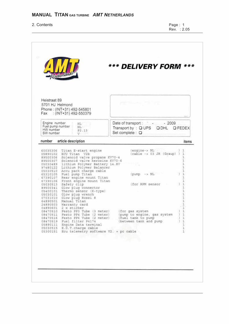
2.1 Turbine The kit consists of a turbine, manufactured with the utmost precision and care, and it is important that you, as a user, treat the motor as a precision instrument. Each new motor has undergone 3 test runs before delivery together with its own ECU and fuel pump. At each test run capacities and performance have been checked and are stored in our database. 2.2 Electronic Control Unit (ECU) The ECU is a control unit, controlled by a microprocessor, which is powered from the fuel pump battery. The control unit has two inputs which are connected to your radio control system, and also inputs for the Exhaust Gas Temperature (EGT) and the RPM of the motor which are used to make sure that the motor cannot exceed the maximum design RPM or EGT. 2.3 Fuel pump The fuel pump is a type built from two gear-wheels running in a high-precision chamber. Therefore it is very important that you use a fuel which is absolutely clean and pure, in order to prevent blockages in the fuel system. Taking the pump apart can lead to irreparable damage. 2.4 Owners Manual It is very important that you study this manual closely before installing or starting the motor, in order to understand the Titan and its systems properly. If there are updates of this manual which are important for safety or operation, then AMT will make sure these are sent to you. 2.5 Sundries The kit also contains a number of additional items such as tubes, Festo connectors, battery charging cables etc. We recommend that you only use tubing from "FESTO" to fit onto the motor and pump connectors, as this guarantees that everything fits properly. If the availability of FESTO components is a problem for you, then please contact AMT NL or your AMT dealer for supplies. The total quantity of the delivered goods is to be found in the packing list.

MANUAL TITAN GAS TURBINE AMT NETHERLANDS Page :1 3. Extra requirements Revision: 2.07
3.1 Fuel Several types of fuel can be used. However, AMT NL recommends that you stick with a fuel type once it has been chosen. It is important to get information about the local availability of your choice of fuel before making this decision. Fuel types 1: Jet A-1 This fuel type is used in commercial aviation. 2: JP-4/Kerosene This fuel type is used in the military aviation. 3: Paraffin This fuel type is mostly used in oil stoves. The Titan also uses the fuel for lubrication, so the fuel must be pre-mixed with 4,5% Aeroshell 500 turbine oil before use. This oil takes care of the lubrication during start-up and power-down sequences. When a power-down is activated the fuel flow stops and each of the above fuel types will vaporize in the hot turbine. At that moment the oil takes care of the lubrication. This remaining oil also lubricates the turbine during the next start-up sequence. Important: Be sure that you use clean fuel, and always use a fuel filter in the tube between the external fuel supply container and the fuel tanks for the motor. 3.2 Starting gas The starting gas used for the pre-heating of the motor is propane. This gas type is often used for hobby blowlamps and has a pressure of approx. 4 Bar at a temperature of 10°C. Starting using a mixture of butane/propane gas is not so reliable, especially in colder climates. The external gas bottle has to be provided with a regulator valve that needs at least three full turns to be completely open. This is necessary so that you can control the amount of gas supplied when using it for starting the motor, and also during the filling of the internal gas container. When you do not use the internal gas container, and use an external one for starting, make sure that the gas container is stable enough and cannot fall over during start-up, as the propane must be supplied to the motor in gaseous form for starting. (NB: If the external propane container falls over it will supply liquid gas, which can be dangerous.)
Page : 2
Rev. : 2.07
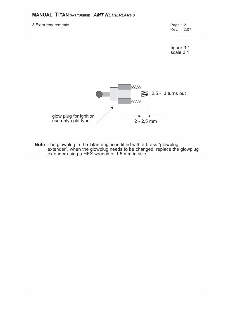
2 - 2,5 mmglow plug for ignitionuse only cold type
Note: The glowplug in the Titan engine is fitted with a brass “glowplugextender”, when the glowplug needs to be changed, replace the glowplugextender using a HEX wrench of 1.5 mm in size.
2.5 - 3 turns out
figure 3.1scale 3:1
3.Extra requrements
MANUAL ITANT GAS TURBINE AMT NETHERLANDS
MANUAL TITAN GAS TURBINE AMT NETHERLANDS Page :2 3. Extra requirements Revision: 2.07
3.3 Compressed air For the air start version of the Titan you need compressed air with a pressure of 10-12 Bar, and starting will use approx. 50 litres per 5 seconds. The simplest way is to use a high-pressure air bottle (scuba diving tank) with a capacity of 10 litres, fitted with a 1st stage regulator set to 10 – 12 Bar. Normally these bottles are filled to a pressure of 200 Bar. Therefore with a 10 litre bottle you have 2000 litres of air, which is enough for 10-15 start-ups and cool-downs. 3.4 Ignition The Titan uses a normal model glow plug (type "cold") for ignition (Rossi R8 supplied). These are available in most hobby stores and must be modified as shown in figure 3.1. The easiest way to do this is by using a piece of bent 1mm steel wire, or a pair of tweezers. These glow plugs are lit by connecting the right voltage. This is often indicated on the package, and is normally 1.5 or 2 volts. It is of the utmost importance that you are absolutely sure that the glow plug is functioning properly before you begin with the start-up procedure. With a defective glow plug you run the risk of too much gas in the motor, which might lead to a fire. When you have problems starting the engine, please check the glow plug first, it should be glowing very bright yellow. Note: From ECU software version V23 and higher you will get “no start clearance” on the EDT display when the glowplug is faulty. However, when all other conditions for start clearance are OK (ie: EGT below 88 deg C, charged pump battery, shaft rpm less than 500) the ECU will still allow you to start the engine, using an external ignition source. When you put the 3 position switch in the ‘start’ position the ECU will still try to start the motor, and proceed with the normal start-up sequence. Warning: When using an external ignition source, like a cigarette lighter, please be extremely careful of the exhaust heat at ignition. Of course, this method is not recommended by AMT Netherlands, expect in emergency cases. 3.5 Fire extinguisher Safety is of the utmost importance, so please make sure that you have a properly functioning fire extinguisher within reach, and take care that at least one of your assistants is able to handle it. A fire extinguisher filled with CO2 or Halon is preferred, because these do not leave harmful residues in the turbine.
4. Safety Page : 1
Rev. : 2.05
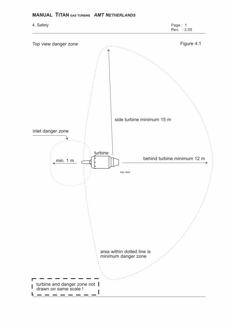
Top view danger zone Figure 4.1
turbine and danger zone notdrawn on same scale !
area within dotted line isminimum danger zone
behind turbine minimum 12 m
side turbine minimum 15 m
inlet danger zone
min. 1 m
turbine
top view
MANUAL ITANT GAS TURBINE AMT NETHERLANDS
MANUAL TITAN GAS TURBINE AMT NETHERLANDS Page :1 4. Safety Revision: 2.05
4.1 General A turbine is a type of motor that needs more safety precautions than the average propulsion system, such as a ducted-fan unit. Therefore it is of the utmost importance that the safety precautions mentioned below are taken into account. 4.2 Assistance Make sure that you have at least one assistant when starting up the turbine. This assistant has to get acquainted with the turbine, just like you. 4.3 Handling the turbine It is advisable to make a test stand to learn about starting and handling the turbine, before installing it in a model. You should make enough test starts in a "clean" space, or better still "outside", until you can handle the turbine properly and with confidence. 4.4 Danger zones Figure 4.1 indicates which areas your assistant, and also bystanders, need to avoid. In any case, do not start the turbine if there are people in these danger zones. 4.5 Noise production A turbine mainly produces noise in the high frequencies. Often these noises are not experienced as annoying, but prolonged exposure may still harm your hearing, and especially as an operator you are intensively exposed to this noise. Therefore please wear sufficient hearing protection when running the turbine. 4.6 Liability AMT Netherlands is not liable in any way for whatever damage or injury, resulting from the use of the Titan electric start or Titan air start turbine.
5. Electronic Control Unit Page : 1
Rev. : 1.5
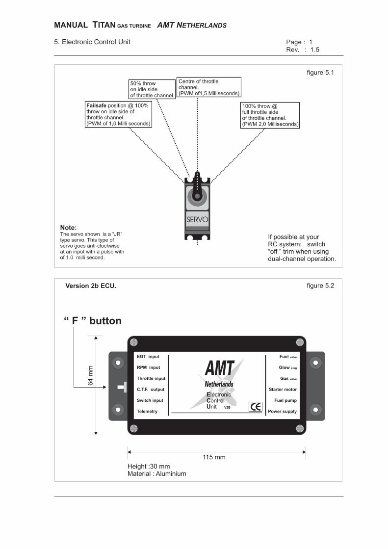
SERVO
If possible at yourRC system; switch“off ” trim when usingdual-channel operation.
figure 5.1
figure 5.2Version 2b ECU.
Switch input
RPM input
EGT input
Throttle input
C.T.F. output
Telemetry Power supply
Fuel pump
Starter motor
Gas valve
Fuel valve
Glow plug
E
C
U
lectronicontrolnit V2B
AMTNetherlands
“ F ” button
position @ 100%throw on idle side ofthrottle channel.(PWM of 1,0 Milli seconds)
Failsafe
50% throwon idle sideof throttle channel.
Centre of throttlechannel.(PWM of1,5 Milliseconds)
100% throw @full throttle sideof throttle channel.(PWM 2,0 Milliseconds)
115 mm
Height :30 mmMaterial : Aluminium
64
mm
MANUAL ITANT GAS TURBINE AMT NETHERLANDS
Note:
The servo shown is a “JR”type servo. This type ofservo goes anti-clockwiseat an input with a pulse withof 1.0 milli second.
MANUAL TITAN GAS TURBINE AMT NETHERLANDS Page :1 5. Electronic Control Unit V2 Revision: 1.5
5.1 Description of ECU The Electronic Control Unit (ECU) controls the gas turbine within the safe software limits, which are pre-set by AMT Netherlands. 5.2 Which radio control system, PPM or PCM are you going to use. In general there are 2 transmission systems available on the market, the older transmission system is called PPM, PPM stands for Pulse Position Modulation and there is a PCM, PCM stands for Pulse Code Modulation. When you decide to use a PPM system please go to chapter 5.3, as the failsafe option is not available in a PPM system. If you are going to use a PCM system you can use the failsafe option of this type of ECU. AMT advises to use a PCM system. 5.2.1 Using a PCM system When you are using a PCM system it is necessary to study the failsafe options of your radio first, best is to power up the TX, connect 2 servo’s and a battery to the receiver and get used to the radio. By doing this the operator can observe, visually, by the movement of the servos, the signals going to the ecu. Program the throw for throttle and switch channel, if you are using dual channel operation, to 100% throw on both sides of the channel. If you are going to use dual channel operation switch off the trim of the throttle channel, if this is not possible leave the trim in the middle position and do not use it during calibration or later when you are operating the turbine. Now go to the failsafe menu of your transmitter and set the failsafe function for your throttle and program the channel to go to “idle” in case of a failsafe condition. Check with a servo connected to the receivers throttle channel if the servo moves to the idle position in case of a failsafe condition. You can generate a failsafe to switch off your transmitter, at switching on the transmitter the servo should move again to the actual throttle position. After the failsafe is programmed and tested the throw of the throttle channel has to be adjusted to 50% throw on the ”idle” side of the throttle channel, the other side of the channel the “full throttle side” must remain on 100% throw. Please check the throttle channel with a servo connected to the receiver and check if the failsafe indeed goes 10-20 deg further that the idle position. Later the ECU will detect this failsafe position and will shutdown the engine after the programmed failsafe time in the ECU. As standard, this failsafe timer is set to a 2-second delay.
Switch input
RPM input
EGT input
Throttle input
C.T.F. output
Telemetry Power supply
Fuel pump
Starter motor
Gas valve
Fuel valve
Glow plug
E
C
U
lectronicontrolnit V2B
AMTNetherlands
5. Electronic Control Unit Page : 2
Power supply
from fuel tank(s)
rpm cable
glowplug lead
glowplug cap (red wire)earth (black wire) under hull bolt
starter
gas
PP6 tubing
PP3 tubing
PP4 tubing
PP6 tubing
PP3 tubing
fuel
exhaust temp. sensor
Figure 5.3
to EDTto RCorFMS
CTFinput
From gas containerfor filling
70% overflow
Use 100% propaneFill only 70 % !!
Starting gasoutput to engine
out in 70%
fuel filter
Starting gascontainer is optionalStarting gascontainer is optional
fuel pump
FG
Pro
pa
ne
SOLE
NO
IDVA
LVE
IN
OU
T
Kero
sene
SOLE
NO
IDVA
LVE
IN
OU
T
Rev. : 1.5
MANUAL ITANT GAS TURBINE AMT NETHERLANDS
MANUAL TITAN GAS TURBINE AMT NETHERLANDS Page :2 5. Electronic Control Unit V2 Revision: 1.5
5.3 Definition of input channels The ECU uses as inputs: A: Exhaust gas temperature (EGT). B: Rotation speed (RPM). C: Throttle channel (receiver / FMS*). D: CTF input and ASU control for air start engines E: Switch channel (receiver / FMS). F: Supply 12-16 volt min.10-12 Amp continues G: Function button The outputs present are: A: Fuel valve connection. B: Glow plug connection. C: Gas valve connection. D: Electric starter connection. E: Fuel pump connection. F: Telemetry, also for EDT connection. *FMS = Flight Management System. 5.3.1 Temperature input A To this input channel a type K (Ni-Cr/Ni) thermo-couple must be connected. The end of the thermo-couple has to be mounted in the appropriate place in the exhaust nozzle of the turbine. (1 - 2 mm inside the exhaust nozzle) Be careful of the polarity of the thermo-couple, the plug and socket have one wide contact and one narrow contact. 5.3.2 RPM input B To this input channel, which records the rate of shaft rotation, connect the plug from the RPM sensor. It is recommended that you use the supplied safety clip to properly fix the RPM connector. If necessary an extension cable is available. (max. 100cm) 5.3.3 Regulator channel input C This input channel is connected to the receiver channel, which is controlled by the throttle of your transmitter. This must be a PWM signal between 1-2 millisecond which repeats every 20-25 milliseconds. 1 millisecond PWM equals 0% throttle, 2 millisecond equals 100% throttle.
Page : 3
side view switch on transmitter
pos.1 pos.2 pos.3
figure 5.4
5.Electronic Control Unit
Rear view 9 pol. connector to P.C.
sub D connectorto PC (female)
Futaba servo cable
figure 5.5
Throttle to thrust relation
figure 5.6
Dual channel operation
Single channel operation
1
6 7 8 9
2 3 4 5
pin 2pin 3pin 5
pin 3pin 2pin 7
RXTXground
blackwhitered
25 pinsub D
9 pinsub D description Futaba
1.2.3.
lowmiddlehigh
1.0 Msec1.5 Msec2.0 Msec
system offpower downstart & running
pos. tone function PWM signal
1.2.3.
lowmiddlehigh
1.0 Msec1.5 Msec2.0 Msec
system offpower downstart & running
pos. tone function PWM signal
1.2.3.
0%100%
lowmiddlehighlowhigh
1.0 Msec1.1 Msec1.2 Msec1.2 Msec2.0 Msec
system offpower downstart & runningIdle RPMMax RPM
pos. tone function PWM signal
trim
0 % throttle
100 % throttle
pos.3pos.2pos.1
Side view transmitter throttle stick
min. RPM 50 % RPM max. RPM
min.50 %max.
30.00070.00097.500
< 17~160>389
NewtonNewtonNewton
Stick RPM Thrust
Switch input
RPM input
EGT input
Throttle input
C.T.F. output
Telemetry Power supply
Fuel pump
Starter motor
Gas valve
Fuel valve
Glow plug
E
C
U
lectronicontrolnit V2B
AMTNetherlands
����
����
�����
�����
�����
�����
�����
�����
�����
�����
����� ����� ����� ����� ���� ���� ����� ������
���� �
Rev. : 1.5
MANUAL ITANT GAS TURBINE AMT NETHERLANDS
MANUAL TITAN GAS TURBINE AMT NETHERLANDS Page :3 5. Electronic Control Unit V2 Revision: 1.5
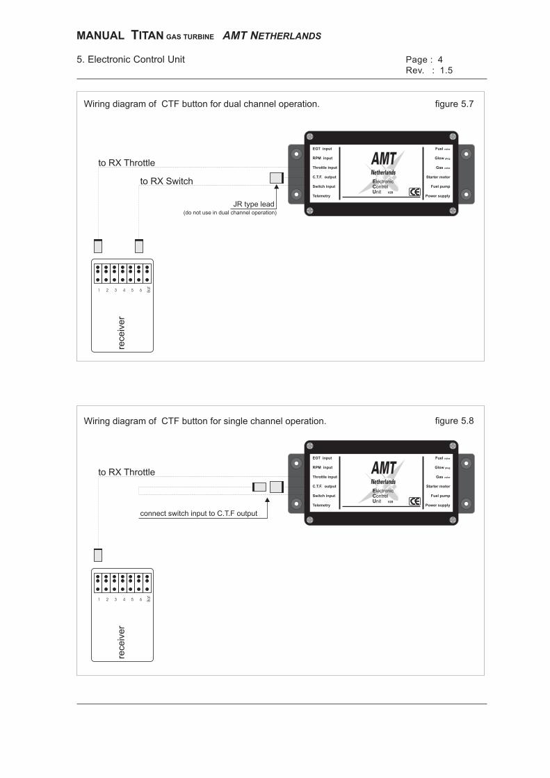
5.3.4 Switch channel input E This input channel is connected to the receiver channel, which is controlled by a 3 position switch of your transmitter or FMS. This must be a PWM signal between 1-2 millisecond which repeats every 20-25 milliseconds. 1 millisecond PWM equals emergency stop position. 1,5 millisecond equals auto power down and 2 millisecond equals the start and running position. 5.3.5 Supply input F The power supply input is designed for a 4 cell Lithium Polymer (Lipo) battery, the advised capacity of the battery pack to be used is 3000-4000 Ma/hour. The supplied pack has a rating of 3350 Ma/hour or higher. The current at full throttle will be between 5 and 6 amps depending on ambient conditions fuel system etc. Note:To have Lipo batteries working properly, they need to be “balanced” on a regular base, a Lipo balancer is included. Lipo chargers and balancing equipment are also separate available from AMT Netherlands. Low battery error at a running engine. The error message “low battery” at a running engine will be generated at 12,0 volt. (3,0 volt for each Lithium Polymer cell) With this error message the engine will go to full stop. Low battery error at a the starting sequence. At the starting sequence the supplied voltage should at least be 14,8 volt or a low battery error will be generated, and the start-up will be aborted. Address 201 for a low battery error at start-up. (error is set at 14.8 volt) Address 200 for low battery error at a running engine. (set at 12,0 Volt) When a different power supply is use used as mentioned above the battery error levels have to be changed in the appropriate way with the supplied TMC program. 5.4.1 Dual channel operation In this mode both input channels (input C & E) are used to control the ECU and therefore the engine. The function button is used to “teach” the ECU the pulse width of your radio system or FMS. To program two channel operation follow this sequence: 1 Connect the throttle lead to the correct channel on your receiver or FMS. 2 Connect the switch lead to the correct channel on your receiver or FMS. 3 Switch “on” Transmitter and receiver or FMS. 4 Push down the ECU function button, and hold it pushed down. 5 Switch “on” the ECU, after a few seconds you will hear a beep. 6 Release the function button.
5. Electronic Control Unit Page : 4
Wiring diagram of CTF button for dual channel operation.
Wiring diagram of CTF button for single channel operation.
figure 5.7
figure 5.8
Switch input
RPM input
EGT input
Throttle input
C.T.F. output
Telemetry Power supply
Fuel pump
Starter motor
Gas valve
Fuel valve
Glow plug
E
C
U
lectronicontrolnit V2B
AMTNetherlands
to RX Throttle
to RX Switch
(do not use in dual channel operation)
JR type lead
1 2 3 4 5 6 Ba
t
rece
ive
r
Switch input
RPM input
EGT input
Throttle input
C.T.F. output
Telemetry Power supply
Fuel pump
Starter motor
Gas valve
Fuel valve
Glow plug
E
C
U
lectronicontrolnit V2B
AMTNetherlands
to RX Throttle
connect switch input to C.T.F output
1 2 3 4 5 6 Ba
t
rece
ive
r
Rev. : 1.5
MANUAL ITANT GAS TURBINE AMT NETHERLANDS
MANUAL TITAN GAS TURBINE AMT NETHERLANDS Page :4 5. Electronic Control Unit V2 Revision: 1.5
7 Put the 3 pos. switch in the “Off” position and push and release the function button. (ECU will giving a beep for confirmation)
8 Put the 3 pos. switch in the “Middle” position and push and release the function button. (ECU will giving a beep for confirmation)
9 Put the 3 pos. switch in the “Start” position and push and release the function button. (ECU will giving a beep for confirmation)
10 Put the throttle in the “Idle” position and push and release the function button. (ECU will giving a beep for confirmation)
11 Put the throttle in the “Max throttle” position and push and release the function button. (ECU will giving a beep for confirmation)
Directly after program sequence no.11 the ECU will give a confirmation beep that all pulse widths are stored in the ECU. When no changes are made in the programming of throttle or switch channels in your transmitter you do not have to do this sequence again before each motor run. When you are using a RC PCM system you can check the failsafe routine by switching OFF your transmitter. When the failsafe time has passed the ECU will sound with a high/ low beep tone. This failsafe beep tone has to be reset like an engine error, see chapter 5.5.2 Note: AMT Netherlands recommends using the dual channel motor operation because it gives the best possibilities for operation of the turbine, meaning a separate switch for starting and stopping the turbine. However if you have only one channel for operating the turbine you can use the combined throttle function as described in the next paragraph. With this combined throttle function the trim lever on your throttle channel acts as the three-position switch as described above. When using the single channel function it is probably better to use a transmitter with a mechanical throttle trim rather than an electronic trim. A mechanical trim allows rapid and accurate positioning of the trim switch, important when the trim position is used to control engine functions as in single channel operation. 5.4.2 Single channel operation Note: The moment you connect the switch channel input E of the ECU into the CTF lead, the ECU operates in single channel mode. (Combined Throttle Function) To program the single channel operation follow this sequence: 1 Connect the throttle lead to the correct channel on your receiver or FMS. 2 Connect the switch lead of the ECU to the CTF lead.
Switch input
RPM input
EGT input
Throttle input
C.T.F. output
Telemetry Power supply
Fuel pump
Starter motor
Gas valve
Fuel valve
Glow plug
E
C
U
lectronicontrolnit V2B
AMTNetherlands
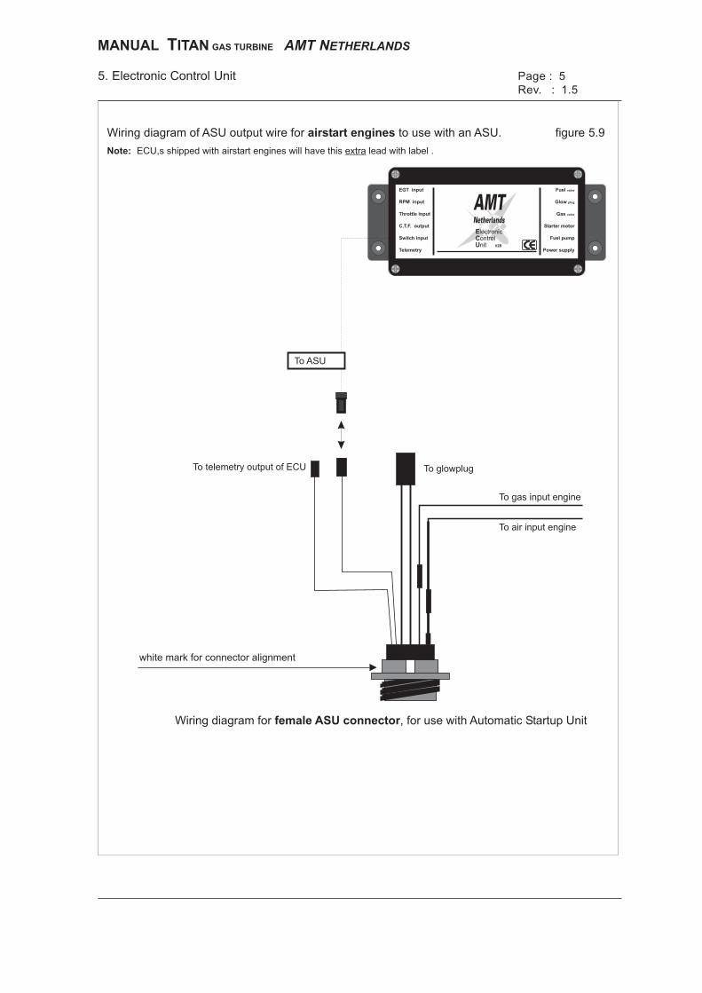
5. Electronic Control Unit Page : 5
ECU,s shipped with airstart engines will have this lead with label .extraNote:
Wiring diagram of ASU output wire for to use with an ASU.airstart engines
To glowplugTo telemetry output of ECU
To gas input engine
To air input engine
Wiring diagram for , for use with Automatic Startup Unitfemale ASU connector
white mark for connector alignment
figure 5.9
To ASU
Rev. : 1.5
MANUAL ITANT GAS TURBINE AMT NETHERLANDS
MANUAL TITAN GAS TURBINE AMT NETHERLANDS Page :5 5. Electronic Control Unit V2 Revision: 1.5
3 Switch “on” Transmitter and receiver or FMS. 4 Push down the function button, and hold it pushed down. 5 Switch “on” the ECU after a few seconds you will hear a beep. 6 Release the function button. 7 Put the throttle in the “Idle” position and put the trim of your throttle channel on
your transmitter in the “Off” position which must be in the same direction as the “idle” position of your throttle stick and push and release the function button. ECU will give a beep for confirmation.
8 Put the trim of the throttle on your transmitter in the “Middle” position and push
and release the function button. ECU will give a beep for confirmation. 9 Put the trim of your throttle on your transmitter in the “On” position which must be
in the same direction as the “full throttle” position of your throttle stick and push and release the function button. ECU will give a beep for confirmation.
10 Leave the throttle in the “Idle” position and push and release the function button. ECU will giving a beep for confirmation.
11 Put the throttle in the “Max throttle” position and push and release the function button. ECU will give a beep for confirmation.
Directly after program sequence no.11 the ECU will give a confirmation beep that all pulse widths are stored in the ECU. When no changes are made in the programming of throttle or switch channels in your transmitter you do not have to do this sequence again before each motor run. You must leave switch channel connected the CTF lead of the ECU. Note: Be sure you have enough “throw” on your throttle trim when your throttle stick is set in the “idle” and in “max” throttle positions. If you are not sure check the throw with a servo connected to your receiver throttle channel. The trim lever of your throttle channel now acts like a three position switch when your throttle stick is at the “idle” position. Best is to go to idle with your throttle stick and only then use the trim for switching purposes. When you are using a RC PCM system you can check the failsafe routine by switching OFF your transmitter. When the failsafe time has passed the ECU will sound with a high low beep tone. This failsafe beep tone has to be reset like an engine error, see chapter 5.5.2 5.4.3 CTF input D to operate Automatic Start-up Unit (air start) For operating and air start engine together with an Automatic Start-up Unit the CTF input also controls the starting sequence of the ASU unit. The instructions for wiring the ASU to the new V2 ECU will be included in the box with he with the Automatic Start-up Unit.

MANUAL ITANT GAS TURBINE AMT NETHERLANDS
MANUAL TITAN GAS TURBINE AMT NETHERLANDS Page :6 5. Electronic Control Unit V2 Revision: 1.5
5.5 Definition of output channels 5.5.1 Fuel valve connection output A This output must be connected to the (red) fuel solenoid valve. When you connect the pp3 tubes to the valve be careful of the correct flow direction, which is clearly marked on the valve with an arrow. 5.5.2 Glow plug connection output B This output must be connected to the glow plug and “earth/negative” of the engine. Only use Rossi 8 glow plugs, as the high current of the ECU internal glow driver will destroy most other glow plugs. For the “earth” connection you should use one of the eight bolts of the engine casing. 5.5.3 Gas valve connection output C This output must be connected to the (blue) propane solenoid valve. When you connect the pp3 tubes to the valve be careful of the correct flow direction, which is clearly marked on the valve with an arrow. 5.5.4 Electric starter connection output D This output must be connected to the electric starter of the engine. 5.5.5 Fuel pump output E
The fuel pump is connected to this output channel with cables of a minimum cross-section area of 2 mm2. The maximum recommended length of cable from the fuel pump to the ECU is 50 cm. 5.5.6 Serial port output F This output can be connected to the Engine Data Terminal or to the serial port of a personal computer, which allows the input data to be visible on the screen. The telemetry software is available from AMT Netherlands.
Page : 75.Electronic Control Unit
figure 5.10error beeps
1.s
tart
ing
up
se
qu
en
ce
/lo
wR
PM
err
or
1. 2. 3. 4. 5. 6.
2.s
witch
inp
ut
ch
an
ne
lfa
iled
3.(
thro
ttle
)re
gu
lato
rin
pu
tch
an
ne
lfa
iled
4.e
xh
au
st
tem
pe
ratu
ree
rro
r
5.h
igh
RP
Me
rro
r
6.p
um
pb
att
ery
em
pty
pause
figure 5.11
(software version 6.23 or higher)
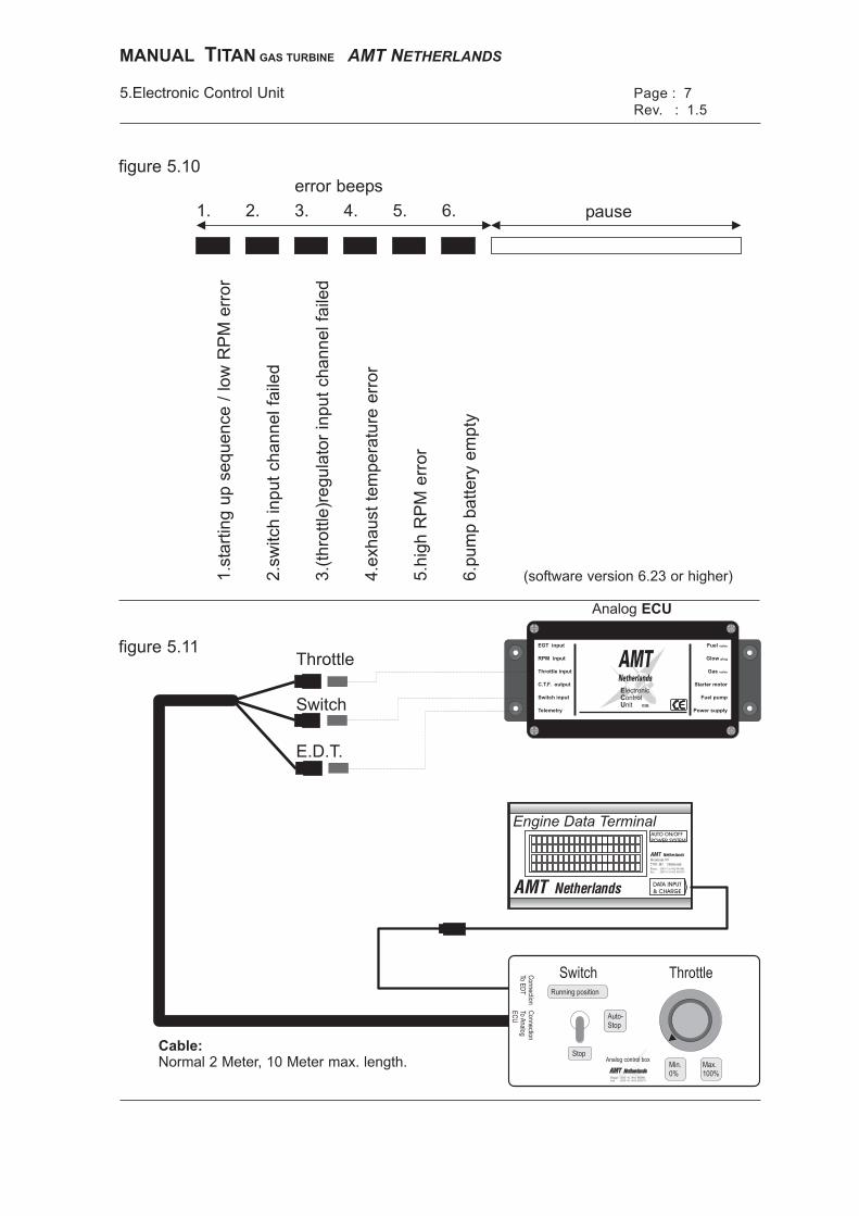
Cable:
Normal 2 Meter, 10 Meter max. length.
Switch Throttle
Min.0%
PhoneFax
(INT+31) 492-545801(INT+31) 492-550379
::
Analog control box
Running position
Auto-Stop
Stop
Connection
ToA
nalogE
CU
Connection
ToE
DT
Max.100%
PhoneFax
(INT+31) 492-545801(INT+31) 492-550379
::
Heistraat 89Helmond5701 HJ
DATA INPUT
& CHARGE
AUTO ON/OFF
POWER SYSTEM
Engine Data Terminal
E.D.T.
Switch
Throttle
Analog ECU
Switch input
RPM input
EGT input
Throttle input
C.T.F. output
Telemetry Power supply
Fuel pump
Starter motor
Gas valve
Fuel valve
Glow plug
E
C
U
lectronicontrolnit V2B
AMTNetherlands
Rev. : 1.5
MANUAL ITANT GAS TURBINE AMT NETHERLANDS
MANUAL TITAN GAS TURBINE AMT NETHERLANDS Page :7 5. Electronic Control Unit V2 Revision: 1.5
5.6 Buzzer 5.6.1 Buzzer beeps The ECU has a built in buzzer which functions as an indicator of the actual state of the system. The different kind of beeps are: OK beep: This beep is a low pitch tone, immediately followed by a high pitch tone. Starting beep: When you activate the starting sequence you will hear a series
of 5 beeps, after the fifth beep the starting sequence will take place. No radio beep: This beep is a low pitch tone with short intervals. It occurs when no switch channel is connected, or when the receiver is off (self resetting). No start-up beep: This beep is a high pitch tone with short intervals. It occurs when you attempt to start up your engine and the exhaust temperature is too high or thermo-couple is disconnected (self resetting). Failsafe beep: This beep is a high / low pitch tone. It occurs when the failsafe
condition of the ECU is active. Error beep: This beep occurs when there is a system error. It consists of six short beeps with a high or low pitched tone. The high or low pitched tone indicates a non-fault, or Fault, condition. The position of the low pitch tone in the six beeps indicates the kind of error. This beep is not self resetting! position 1: start-up sequence error or low RPM error. position 2: switch input channel failed. position 3: regulator input channel failed. position 4: exhaust temperature error. position 5: high RPM error. position 6: low supply error. When an error occurs the type of error will be displayed on the bottom line of text on the EDT. When you reset the ECU error (5.4.2) also the error message in the EDT will be removed from the bottom line.

MANUAL ITANT GAS TURBINE AMT NETHERLANDS
MANUAL TITAN GAS TURBINE AMT NETHERLANDS Page :8 5. Electronic Control Unit V2 Revision: 1.5
5.6.2 Resetting the error beep. When an error beep occurs, it must be reset before normal operation can proceed. Resetting errors for dual channel operation. To reset an error beep you must put the 3-position switch on the transmitter into the switch into the ‘off’ position (low pitch tone) and put the throttle stick into the full throttle position (high pitch tone). For a description of controls see manual section 7.2. Also switching the ECU power off will reset the error message. Resetting errors for single channel operation. To reset an error beep you must put the throttle trim on the transmitter into the ‘off’ position (low pitch tone) and put the throttle stick into the idle throttle position (low pitch tone). Now push the CTF switch for 2-3 seconds to reset the error message. For a description of controls see section 7.2 of the manual. Also switching the ECU power off will reset the error message. 5.7 Analog ECU and control box. AMT Netherlands can supply an “analog “ ECU and control box, this type of ECU is often used when the turbine engine is used stationary in for example a university. With this ECU you do not need to use an RC equipment to operate the engine, this ”analog” ECU works except for the 2 inputs, throttle and switch, the same as the “normal” ECU. For a description of controls see figure on the left. 5.8 Extra features. From software version V24 and higher this Version 2 ECU has several options which are very useful especially when you are installing the system into a jet model. As mentioned above these options are available in Version 24, probably higher versions will have more features as mentioned below. To know which version is available at this moment you can send an E-mail to [email protected], the AMT Netherlands E-mail server will send an E-mail with the current version number and its extra features in a list like below. 10% Not in use at this moment. 20% Not in use at this moment. 30% Glow plug switches on. (will switch on glow plug.) 40% Not in use at this moment. 50% Priming function. (will open fuel valve and activate fuel pump.) 60% Not in use at this moment.

MANUAL ITANT GAS TURBINE AMT NETHERLANDS
MANUAL TITAN GAS TURBINE AMT NETHERLANDS Page :9 5. Electronic Control Unit V2 Revision: 1.5
70% Not in use at this moment. 80% Activation of starter motor . (will activate electric starter.) 90% Clutch check. (will activate clutch check, on/off for 0,5 second interval.) 100% Quick cooling function. (will activate speed-cooling* function.) *At activating the quick cooling function, the E starter motor will keep the turbine shaft continuously spinning, even with released CTF button, until cool-down temperature is reached. A timeout of 1 minute will stop the E-starter in case of a damaged EGT probe. 5.8.1 Activating of extra features in dual channel operation To activate extra features dual channel mode, please handle as follows: • Switch on the TX, RX or FMS and the ECU. • Calibrate the ECU as described in chapter 5.4.1 for dual channel operation, when
ECU was already in dual channel operation you do not have to do this again. • Put the 3 position in the “off” position. • Put your throttle the desired position. (e.g. 50% for the priming function). • Now push the function switch, after 2 seconds the selected feature will be activated. • Releasing the function switch will deactivate the function. 5.8.2 Activating of extra features in single channel operation To activate extra features single channel mode, please handle as follows: • Switch on the TX, RX or FMS and the ECU. • Calibrate the ECU as described in chapter 5.4.2 for single channel operation, when
ECU was already in single channel operation you do not have to do this again. • Push down the function switch for 5 seconds until you hear a confirmation beep • Put your throttle the desired position. (e.g. 50% for the priming function). • Now push the function switch, for 3 seconds after releasing the selected feature will
be activated. • Power down of the ECU will deactivate the function. When there is a function which would be useful and not available in the above list please send us an E-mail with a description of its function.
2
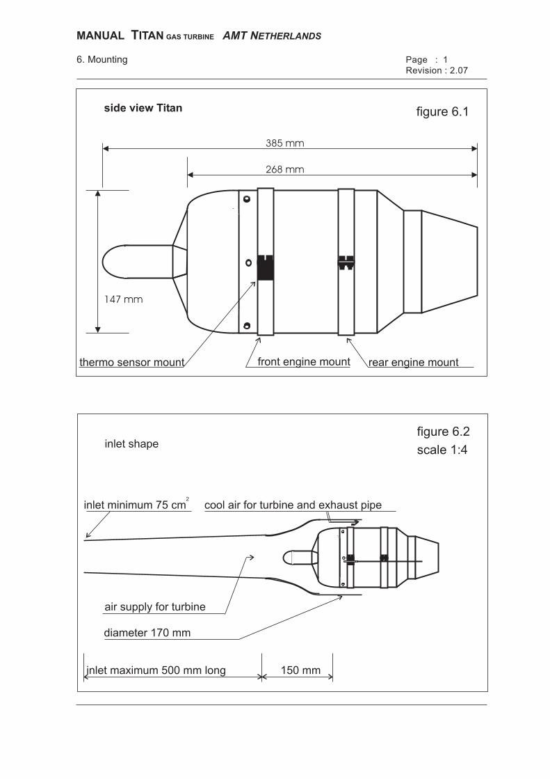
inlet minimum 75 cm
150 mminlet maximum 500 mm long
diameter 170 mm
cool air for turbine and exhaust pipe
air supply for turbine
inlet shapefigure 6.2
scale 1:4
6. Mounting Page : 1
Revision : 2.07
rear engine mountfront engine mountthermo sensor mount
385 mm
268 mm
147 mm
figure 6.1side view Titan
MANUAL ITANT GAS TURBINE AMT NETHERLANDS
MANUAL TITAN GAS TURBINE AMT NETHERLANDS Page :1 6. Installation Revision: 2.07
6.1 Dimensions of Titan E-start. Figure 6.1 shows in scale 1:2 the dimensions of the Titan E-start. Note that the 147mm dimension is the max. diameter of the casing, and does not include the mounting brackets and external connections etc. 6.2 Position of Turbine. The Titan should be mounted in such a way that the fuel connection is approximately at the bottom of the engine (see figure 1.1, chapter 1). Positioning of the turbine behind the 'Centre of Gravity' of the model is usually preferable because then the exhaust ducting does not need to be unnecessarily long. You also save space at the 'Centre of Gravity' position, which is the optimum position for the fuel tanks. You must ensure a minimum clear distance of 10mm all around the turbine casing, between it and the bypass ducting (if used) or any bulkheads or formers in the model. A continuous air stream all around the motor must be maintained for proper cooling. 6.3.1 Inlet shape and dimensions. The Titan has an inlet of 76 mm in diameter. This is equal to a surface area of 45,35 cm2. The air inlet duct of your vehicle needs a minimum area of 75 cm2 (see figure 6.2). In case the total inlet length is more than 50 cm, then it is recommended to use an inlet area of at least 90 cm2. 6.3.2 Air inlet duct. The air inlet duct to the Titan may not have sharp angles or edges, these should be smooth and aerodynamic. A bad aerodynamic shape, and/or not enough air flow, will have a negative influence on the Titan, and this will result in a higher exhaust temperature and a higher noise level on the inlet side of the engine. As material for the inlet and engine bypass duct we recommend the use of a high quality temperature-resistant epoxy resin, which is resistant to approximately 100 C° (after curing), because the front of the motor casing has a temperature of approx. 100 C° at full power. When the turbine is running the continuous air stream between the outside of the motor casing and the inside of the fiberglass ducting around the motor (which should have an inside diameter of 170mm) is being cooled properly. The moment the motor is switched off, the most critical phase for the inlet and engine ducting begins, because there is no cooling anymore. A small external electric fan (like that used for cooling inside PC’s) can be applied to the inlet duct to assist in cooling the turbine and ducting, if necessary.
6-8 mm
6-8 mm
15 mm
figure 6.3
80 mm 0 - 500 mm
exhaust pipe 7-10 mmout of fuselage
120 mm100 mm
110 mm
140 mm
model exhaustminimaal 130 mm
fuselage
exhaust pipe
air flow
inlet pipe 170 mm diameter
exhaust pipe shape
exhaust pipe
figure 6.4
6. Mounting Page: 2
Rev. : 2.07
MANUAL ITANT GAS TURBINE AMT NETHERLANDS
MANUAL TITAN GAS TURBINE AMT NETHERLANDS Page :2 6. Installation Revision: 2.07
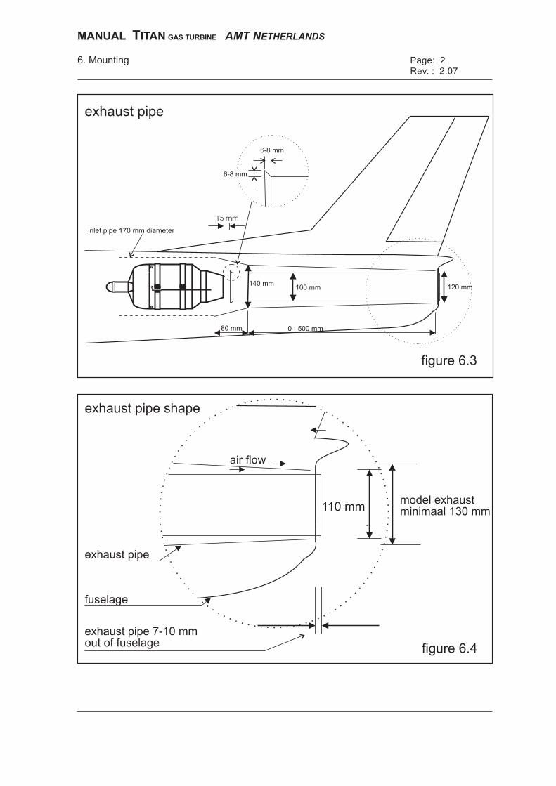
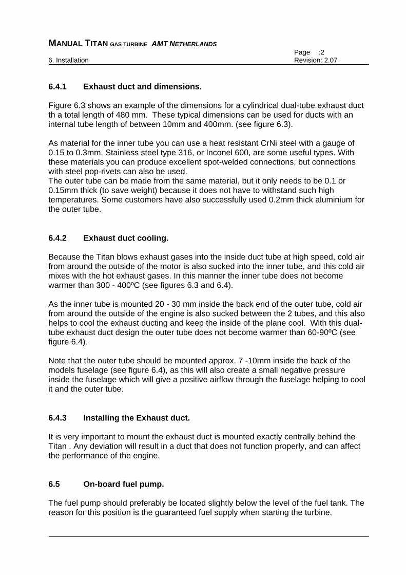
6.4.1 Exhaust duct and dimensions. Figure 6.3 shows an example of the dimensions for a cylindrical dual-tube exhaust duct th a total length of 480 mm. These typical dimensions can be used for ducts with an internal tube length of between 10mm and 400mm. (see figure 6.3). As material for the inner tube you can use a heat resistant CrNi steel with a gauge of 0.15 to 0.3mm. Stainless steel type 316, or Inconel 600, are some useful types. With these materials you can produce excellent spot-welded connections, but connections with steel pop-rivets can also be used. The outer tube can be made from the same material, but it only needs to be 0.1 or 0.15mm thick (to save weight) because it does not have to withstand such high temperatures. Some customers have also successfully used 0.2mm thick aluminium for the outer tube. 6.4.2 Exhaust duct cooling. Because the Titan blows exhaust gases into the inside duct tube at high speed, cold air from around the outside of the motor is also sucked into the inner tube, and this cold air mixes with the hot exhaust gases. In this manner the inner tube does not become warmer than 300 - 400ºC (see figures 6.3 and 6.4). As the inner tube is mounted 20 - 30 mm inside the back end of the outer tube, cold air from around the outside of the engine is also sucked between the 2 tubes, and this also helps to cool the exhaust ducting and keep the inside of the plane cool. With this dual-tube exhaust duct design the outer tube does not become warmer than 60-90ºC (see figure 6.4). Note that the outer tube should be mounted approx. 7 -10mm inside the back of the models fuselage (see figure 6.4), as this will also create a small negative pressure inside the fuselage which will give a positive airflow through the fuselage helping to cool it and the outer tube. 6.4.3 Installing the Exhaust duct. It is very important to mount the exhaust duct is mounted exactly centrally behind the Titan . Any deviation will result in a duct that does not function properly, and can affect the performance of the engine. 6.5 On-board fuel pump. The fuel pump should preferably be located slightly below the level of the fuel tank. The reason for this position is the guaranteed fuel supply when starting the turbine.
side view
top view
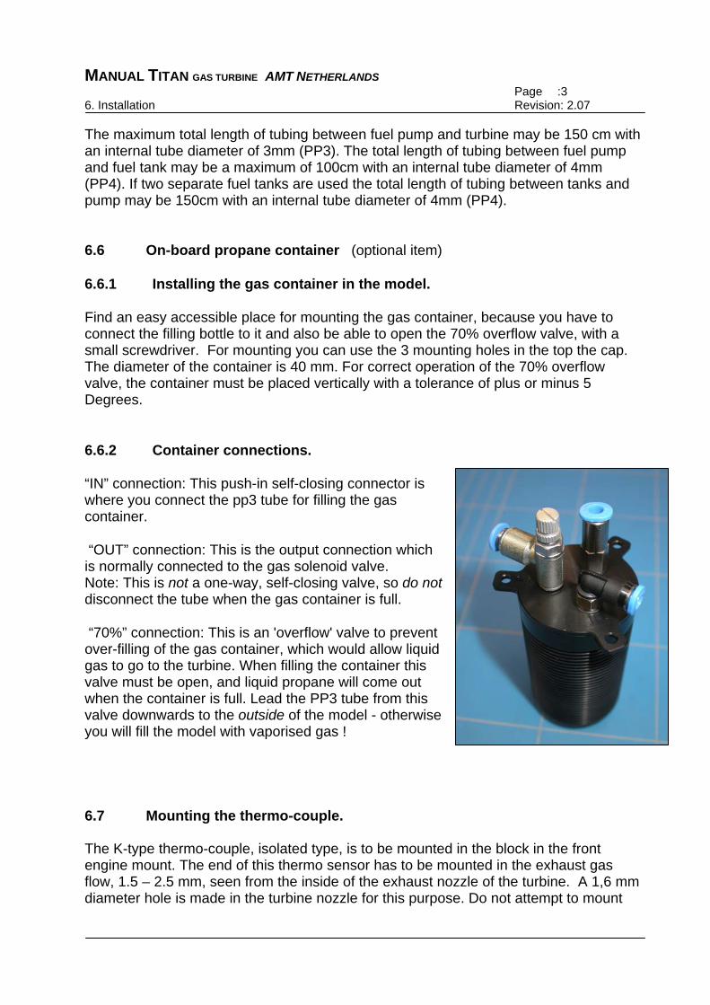
Note: put thermo couple2.5 - 3.5 mm inside exhaust.
6. Mounting Page : 3
Rev. : 2.07
fuel tank
figure 6.6
figure 6.7
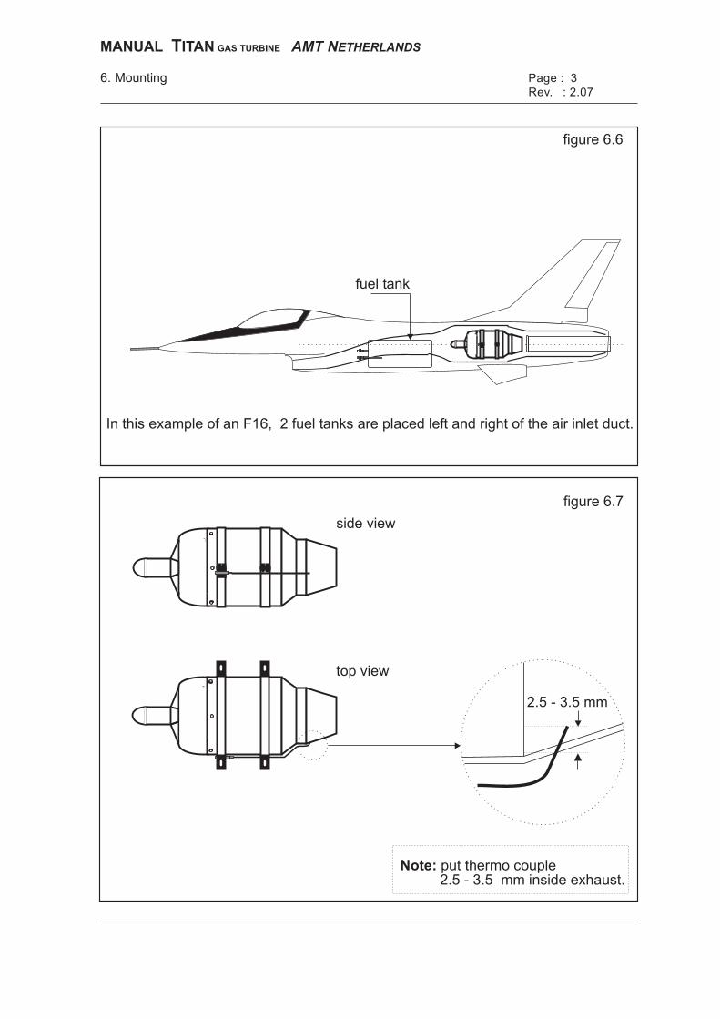
In this example of an F16, 2 fuel tanks are placed left and right of the air inlet duct.
2.5 - 3.5 mm
MANUAL ITANT GAS TURBINE AMT NETHERLANDS
MANUAL TITAN GAS TURBINE AMT NETHERLANDS Page :3 6. Installation Revision: 2.07
The maximum total length of tubing between fuel pump and turbine may be 150 cm with an internal tube diameter of 3mm (PP3). The total length of tubing between fuel pump and fuel tank may be a maximum of 100cm with an internal tube diameter of 4mm (PP4). If two separate fuel tanks are used the total length of tubing between tanks and pump may be 150cm with an internal tube diameter of 4mm (PP4). 6.6 On-board propane container (optional item) 6.6.1 Installing the gas container in the model. Find an easy accessible place for mounting the gas container, because you have to connect the filling bottle to it and also be able to open the 70% overflow valve, with a small screwdriver. For mounting you can use the 3 mounting holes in the top the cap. The diameter of the container is 40 mm. For correct operation of the 70% overflow valve, the container must be placed vertically with a tolerance of plus or minus 5 Degrees. 6.6.2 Container connections. “IN” connection: This push-in self-closing connector is where you connect the pp3 tube for filling the gas container. “OUT” connection: This is the output connection which is normally connected to the gas solenoid valve. Note: This is not a one-way, self-closing valve, so do not disconnect the tube when the gas container is full. “70%” connection: This is an 'overflow' valve to prevent over-filling of the gas container, which would allow liquid gas to go to the turbine. When filling the container this valve must be open, and liquid propane will come out when the container is full. Lead the PP3 tube from this valve downwards to the outside of the model - otherwise you will fill the model with vaporised gas ! 6.7 Mounting the thermo-couple. The K-type thermo-couple, isolated type, is to be mounted in the block in the front engine mount. The end of this thermo sensor has to be mounted in the exhaust gas flow, 1.5 – 2.5 mm, seen from the inside of the exhaust nozzle of the turbine. A 1,6 mm diameter hole is made in the turbine nozzle for this purpose. Do not attempt to mount
6. Mounting
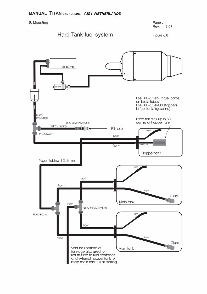
Hard Tank fuel system
Page : 4
Rev. : 2.07
Figure 6.8
Fill here
Hopper tank
Main tank
Clunk
Clunk
Main tank
FESTO valve #QH-QS-8
Fixed felt pick up in 3Dcentre of hopper tank
FESTO # FCK-3-PK6 KU
FCK-3-PK6 KU
Use DUBRO #512 fuel barbson brass tubes.Use DUBRO #400 stoppersin fuel tanks (gasoline)
Tygon tubing I.D. 6 mm
FESTOPP-6 tubing
FESTO PP-6 tubing
Tygon
Tygon
Tygon
Tygon
Tygon
Tygon
Tygon
Tygon
Tygon
Tygon
Brass tube
Tygon
Tygon
Vent thru bottom offuselage also used forreturn tube to fuel containerand external hopper tank tokeep main tank full at starting.
FCK-3-PK6 KU
fuel pump
F
MANUAL ITANT GAS TURBINE AMT NETHERLANDS
KeroseneSOLENOID VALVE
IN
OUT
MANUAL TITAN GAS TURBINE AMT NETHERLANDS Page :4 6. Installation Revision: 2.07
the thermo-couple more than 3.0 mm inside the exhaust nozzle, as this might give incorrect temperature readings and damage the thermocouple. To mount the thermo-couple it should be bent as shown in figure 6.7. The sensor has a lead of 90 cm, but it may be shortened. (watch the polarity). 6.8 On-board ECU. The ECU is made of valuable and sensitive electronic components, and therefore it should be installed using the attached mounting brackets with rubber grummets, do not over tighten the bolts which going though the centre of the rubber grommet AMT advises installation of the ECU, battery and fuel pump near to each other so that the standard length cables on all these items are long enough. A longer RPM-sensor cable can be supplied by us (JR type, max. 100cm) if desired. Please do not modify, lengthen, or change the cables, plug connectors or ECU switch on the battery, pump or ECU on your own. These high-quality parts have been specially selected for this purpose, and changing them may affect the proper operation of the turbine, or void the warranty. 6.9 Hard fuel tank installation Many modellers wish to fit hard tanks in their jet models, instead of the plasma bag type. If this is required, please follow the recommendations and hints below, and the diagram (figure 6.8) on the opposite page. • Make sure all the stoppers in all main and hopper tanks are of the type suitable for
gasoline and kerosene. The plastic stoppers normally supplied with most model fuel tanks are only suitable for Methanol based fuel and will be damaged by kerosene fuels. Replace these with stoppers designed for petrol.(e.g.: Dubro part# 400)
• All the tubing used in the fuel system must be suited to kerosene type fuels. The
yellow Tygon tubing, and Festo PP3 and PP4 tubes supplied with your AMT turbine are all suitable for use with kerosene based fuels.
• It is very important that no big air bubbles can be drawn into the fuel pump, so we
recommend that you install a Hopper tank between the main tank(s) and the pump. The feed tube inside the hopper tank, that takes fuel to the pump, should be fitted with a felt-covered fuel pickup, which helps to prevent big air bubbles in the system. This felt pick-up should be fitted in a fixed position in the 3-D centre of the tank. We recommend that it is soldered (or glued with 24 hour epoxy) onto the end of the brass feed tube. It is best if the cross-sectional shape of the hopper tank is square or circular, rather than oval, so that there is the maximum distance between the pickup and the sides of the tank, where the air bubbles are. Suitable felt pickups include the Webra pt # 1122 , available from AMT. We recommend a minimum hopper tank capacity of 400 ml (14 fl.oz) for the Titan engine.
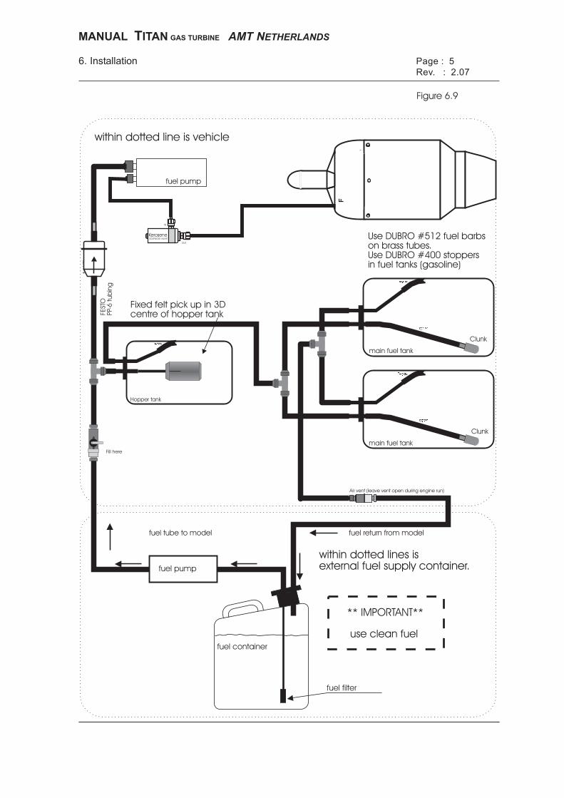
Page : 5
Rev. : 2.07
Figure 6.9
main fuel tank
main fuel tank
Clunk
Clunk
Hopper tank
�����
�����
�����
�����
�����
Fill here
Air vent (leave vent open during engine run)
fue
lfilt
er
fue
l filt
er
fue
l filt
er
** IMPORTANT**
use clean fuel
fuel tube to model fuel return from model
within dotted lines isexternal fuel supply container.
fuel container
fuel filter
fuel pump
within dotted line is vehicle
6. Installation
Fixed felt pick up in 3Dcentre of hopper tank
Use DUBRO #512 fuel barbson brass tubes.Use DUBRO #400 stoppersin fuel tanks (gasoline)
FEST
OPP-
6tu
bin
g
fuel pump
F
KeroseneSOLENOID VALVE
IN
OUT
MANUAL ITANT GAS TURBINE AMT NETHERLANDS
MANUAL TITAN GAS TURBINE AMT NETHERLANDS Page :5 6. Installation Revision: 2.07
• To prevent any possibility of fuel being forced through the pump into the turbine
during fuelling up the model (which would cause a ‘wet-start’), the Version 2 ECU controls a high flow kerosene valve which only opens when the fuel pump is running.
• If using 2, or more, main tanks that require Tee pieces, use the proper Festo Tee
(part# FCK-3-PK4 KU), not the plastic tees that are supplied with most model fuel tanks as these are not suitable for kerosene, and may also allow air into the fuel system. Make sure that the length of tubing from each tank to the Tee piece is equal, so that the same amount of fuel is sucked from each tank during operation.
It is also important that the level of both tanks in the model are equal. • Use flexible yellow Tygon tubing between the brass feed tube in the tank stopper
and the clunk weight inside the main tank(s). Make sure that the clunk weight is heavy enough to allow it to move easily during flying manoeuvres.
• The inside diameter of the tubes used for turbine installation are larger than for
normal model engines, and therefore a loose fit on the standard 1/8” (3.2mm) diameter brass tubes supplied with most model fuel tanks. To make sure that the Tygon tubing cannot come off the brass tubes, or leak any air into the system, we recommended that all brass tubes are fitted with the Dubro fuel barbs (Dubro part# 512) which are soldered onto the brass tubes. These are available from most hobby shops, or we can supply them if required.
6.10 Fuelling up Important: Before fuelling up the model, make sure that the ECU is switched ‘off’ to be sure that the solenoid fuel valve is closed and no fuel can be forced through the pump into the turbine, which would cause a ‘wet-start’. a) Connect the feed tube from the fuel pickup in the external fuel container to the tube
that goes into the hopper tank, with the felt clunk on the end of it. This can be done easily via a Festo QH-QS-6 valve, as shown in figure 6.9. AMT highly recommend that you install a good quality fuel filter in the filling tube between your external fuel container and the model.
b) Connect a return tube from the model’s fuel tank air vent tube (normally under the fuselage) back to the vent on the external fuel container.
c) Start pumping fuel into the model, and keep pumping until the hopper tank and main tank(s) are full, and no large air bubbles remain. The fuel will overflow through the return tube, back into the external fuel container.
d) Disconnect the filling tube from the tube that goes into the hopper tank, and then disconnect the return tube from the air vent under the model. Leave the vent tube open - do not block it.

MANUAL TITAN GAS TURBINE AMT NETHERLANDS Page :6 6. Installation Revision: 2.07
6.11 Alternative method for fuelling up the model If using this alternative fuelling system (below) the main fuel tank(s) in your model will remain full after you have started the turbine, until you taxi out for take-off, and this is very useful at some large model meetings where it is often necessary to wait before take-off is permitted.
• Fuel up as above following points (a) to (d) exactly.
• Reconnect the fuel feed tube from the external fuel container to the model’s fuel tank air vent tube (under the fuselage). Leave the return hole in the external fuel container open/unblocked.
• Start the turbine in the normal way. The main and hopper tanks in model will remain full, automatically sucking the extra fuel needed from external container, until you are ready for taxi and take-off. At this time just disconnect the tube from the external fuel container to the vent under the model. In this way you will always have full fuel tanks at takeoff.

MANUAL TITAN GAS TURBINE AMT NETHERLANDS Page :1 7. Operation Revision: 2.08
7.1. Fueling 7.1.1 Fueling kerosene Fuel up the model as described in chapter 6. Important note: If fuel enters the turbine by accident, empty the turbine by putting the model in a vertical position, with the exhaust nozzle and ducting downwards for at least 15 minutes to ensure that all fuel has drained out, and the remaining fuel in the motor and ducting has evaporated. 7.1.2 Fueling propane (optional gas container) When you use the internal gas container we advise you to fill it before every flight, and to take extra care of safety precautions during this operation - for example no smoking or naked lights nearby ! To fill the internal gas container follow these steps in order: 1. Connect your external propane storage container to the “in” Festo connection on the
gas container in the model with a transparent Festo pp3 tube, so that you can easily see the liquid propane going into the gascontainer in the model.
2. Connect a length of transparent pp3 tube to the “70%” overflow Festo connection on the internal gas container and run it out of the bottom of the model. (This tube can be fitted in the model permanently if you wish).
3. Fully open the valve on your external storage container. 4. Fully open the screw on the “70%” valve on the gas container in the model. 5. Put the external storage container upside down to allow a flow of liquid propane into
the gas container in the model. (observe the flow through the transparent tube) 6. The moment that liquid propane comes out of the “70%” overflow put the external
storage container into the normal upright position and close its valve immediately. 7. Fully close the valve on top of the “70%” overflow output. 8. Disconnect the external storage container from the gas container in the model. Be
careful of any surplus propane coming out of the transparent filling tube of your external storage container.
Note: In some countries or regions flying a model airplane with liquid propane on-board may be prohibited, and AMT staff personally prefer to use an external propane container for safety reasons anyway. For this it is only necessary to add a Festo quick-connect fitting in a convenient location (either inside or on the outside of your model), connected to the gas solenoid valve with pp3 tubing, and use this to connect your external propane container during starting. If using this method, please make sure that no dirt can get into the propane inlet fitting on the model, as this may be blown into the engine on future starts. Important note: Wait at least 5 minutes to give the on-board gas container the time to warm up, because low temperature gives low gas pressure and therefore low gas flow. With low gasflow the startup sequence takes more time.
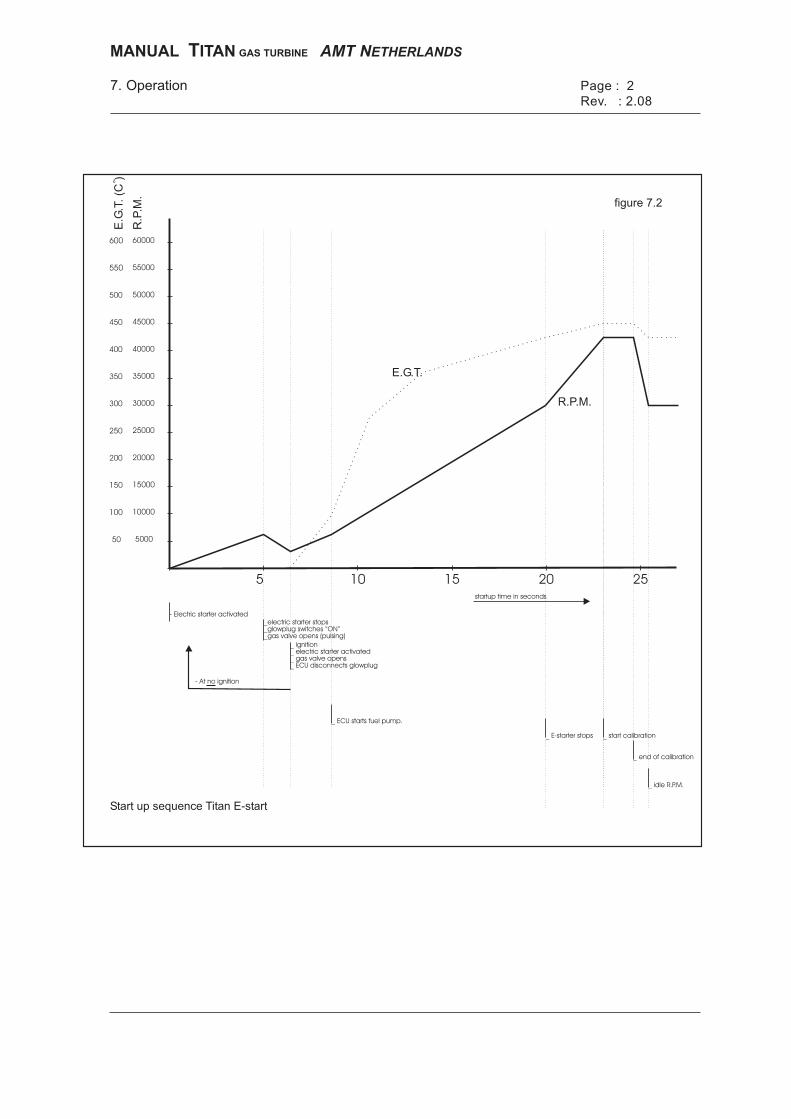
7. Operation Page : 2
Rev. : 2.08
figure 7.2
R.P.M.
E.G.T.
Start up sequence Titan E-start
- Electric starter activated_electric starter stops_glowplug switches “ON”_gas valve opens (pulsing)
_ ignition_ electric starter activated_ gas valve opens_ ECU disconnects glowplug
_ ECU starts fuel pump.
_ E-starter stops
startup time in seconds
_ end of calibration
_ start calibration
_ idle R.P.M.
5 10 15 20 25
10000
15000
20000
25000
30000
35000
40000
45000
50000
55000
60000
R.P
.M.
o
E.G
.T.(C
)
500050
100
150
200
250
300
350
400
450
500
550
600
- At no ignition
MANUAL ITANT GAS TURBINE AMT NETHERLANDS
MANUAL TITAN GAS TURBINE AMT NETHERLANDS Page :2 7. Operation Revision: 2.08
7.2 Powering up the system It is necessary to calibrate the 2 input channels before you can operate the turbine because there are a variety of radio control systems with their own pulse widths. For calibration see chapter 5.4.2.1 for dual channel operation, or 5.4.2.2 for single channel operation. Once this calibration sequence is done the pulse width is stored in the ECU and it does not need to be done again, unless the throttle or switch channel programming in your Transmitter is changed. 1 Be sure everything is properly connected to the ECU. Do not use dual rate,
exponential or logarithmic servo control, servo limiting, idle trim or trim memory to either of the 2 input (throttle and switch) channels.
2 If you use a PCM transmitter switch on your transmitter before your receiver. After this switch on the ECU. You should hear the “OK beep”. If you do not hear this beep please check your pump battery and its connections. If you hear a “no start up beep” (high pitch tone with short intervals) the thermo- couple is disconnected or broken. If you hear a “hardware error beep” (continuous low pitch tone) please contact AMT Netherlands or your AMT NL dealer. 3 If you are using dual channel operation you should get the 3 beeps (low, middle
and high) from the 3 position switch and 3 beeps from the throttle. 4 If you are using single channel operation you should get the 3 beeps (low,
middle and high) from the throttle trim, when throttle is on idle, and 3 beeps from the throttle when you move the stick from idle the max throttle. You can also monitor these positions when using the optional Engine Data Terminal (see chapter 11.5)
5 It is a good idea to check throttle and switch (or throttle and trim) operation
before every flight, by listening for the beeps as described above. 7.3 Starting the Titan E-start (ECU software version 6.14 or higher)
Note: AMT recommends that you fully charge the ECU/pump nicad battery before every flight, to be sure that you have the maximum energy possible for powering the electric starter and glowplug to ensure reliable starting.
Power up the system as described in 7.2. 1 Put the throttle in the idle position (low pitched beep). 2 Put the 3-position switch (or throttle trim lever for single channel operation) on
the transmitter in the 'off' position (low pitched beep).

MANUAL TITAN GAS TURBINE AMT NETHERLANDS Page :3 7. Operation Revision: 2.08
3 When you use an external gas tank, instead of an internal gas container, connect
this gas tank to the system and open the regulator valve fully. 4 To start the turbine put the switch (or throttle trim lever) on the transmitter in the
'start/run' position (high-pitched beep). Now you will hear 5 beeps from the ECU, and then it will begin the start sequence and the electric starter motor will turn the turbine. The glowplug will be switched off automatically as soon as the turbine has ignition. Note: If you try to start the turbine and you hear a continous high pitched tone with short intervals, the engine's exhaust temperature is to high for restarting. (Above 88°C). Leave the switch (or trim lever) in the middle position in order to cool the engine. When it has cooled down switch over to the starting position.
5 The ECU will automatically start the fuel pump and open the fuel solenoid valve
when the RPM reaches 7,000 RPM and the EGT exceeds 88 °C. If using an external gas container, keep the starting gas regulator fully open until the ECU is passing idle RPM (30,000 RPM).
6 The ECU will automatically throttle up the turbine to its calibration point at
approx. 42,000 RPM. (Now you can disconnect and remove the external gas container, if used). The ECU will keep the turbine at approx. 42,000 RPM for about 2 sec and then it will automatically throttle back down to idle RPM (30,000). Idle RPM is now calibrated.
7 You now have control over engine thrust with the throttle stick on your transmitter. Note: When you throttle up for the first time after starting, the engine power is limited to about 95% for 1 - 2 seconds for internal calibration of the ECU. Therefore when you want maximum power for take-off you should make sure that you have first throttled up to full power one time, and held the throttle stick there for at least 2-4 seconds. If you are using our optional ‘EDT’ then as soon as you see “Max RPM set” in the bottom row of text, this is confirmation that you will have maximum power the next time you throttle up. 7.4.1 Stopping the engine For the normal stopping of the engine you should use the automatic “power-down” sequence which functions as follows: - Put the nose of the model into the wind if possible. - Put the switch (or trim lever) on your transmitter to the middle position to activate the automatic power-down sequence.

MANUAL TITAN GAS TURBINE AMT NETHERLANDS Page :4 7. Operation Revision: 2.08
- The ECU now regulates the engine to 5 % throttle (approx. 40,000 RPM) for about 10 seconds and waits until the exhaust temperature stabilizes. Be careful - there is still about 4 kg of thrust at this RPM.
- After this the ECU will stop the engine. - Then the ECU will automatically switch the Electric-starter on and off several
times, until the EGT is below 88 °C. The ECU is now ready for a new start-up. 7.4.2 Switching off in case of an emergency If, in case of an emergency, the turbine needs to be switched off quickly, you can immediately switch over to position 1 “off” (low pitch tone) using the 3 position switch, or throttle trim lever if using single channel operation. The ECU will now stop the turbine immediately from any RPM or power setting. You should only use this method in emergency cases and if fail-safe programming is possible in your transmitter (PCM transmission mode). The advantage of the programmed 'power-down' sequence is that the turbine is switched off with the coldest possible motor and at a relatively low RPM, which is best for the fatigue and the wear of the ball bearings. 7.5 Recommended fueling and charging sequence From the experience of AMT staff we have found that the following sequence between flights works well. It allows the internal gas container the longest time to return to ambient temperature after filling, giving the most reliable starting because of the higher temperature and pressure in the container. 1. Fill the internal gas container in the model before every flight with liquid propane,
using the “70%” overflow valve to make sure that it is full (see 7.1.2). 2. Connect fast nicad charger to the ECU/pump battery and start charging. 3. Fill fuel tanks while charging is taking place. 4. Recharge Receiver nicad (and transmitter) if necessary. Note: AMT highly recommend recharging the ECU/pump battery before every flight, and a complete slow discharge and recharge after each day of flying. Note: When you are using the supplied Lipo batteries AMT Netherlands recommends to balance the battery at least every fith charge with the supplied balancer.

MANUAL TITAN GAS TURBINE AMT NETHERLANDS Page :1 8. Maintenance Revision: 2.09
8.1 Preventative maintenance These are maintenance checks and procedures that the enduser can do according to the time schedule shown. 8.1.1 Visual inspection of the turbine and gear Check the following things after each 1 hour of running time of the turbine: - Visually inspect the outer casing of the turbine, especially for colour changes which indicate extreme temperature rises. - Inspect the mounting brackets for possible cracks. - Look for damage to the inlet and compressor wheel. - Is the fuel pump still sealed and not leaking ? - Are the fuel tank(s) still sealed and not leaking ? - Check that turbine and compressor wheel are not dragging. - Check and if needed change the Festo fuel filter in the vehicle and in your
external fuel container at least every 200 litres of fuel. AMT NL recommends replacing the filters every 100 litres of fuel, or sooner if they are very dirty.
8.1.2 Checking of bearings If you turn the engine shaft by hand, you can judge reasonably well the condition of both ball bearings. Watch for the following things: If the turbine produces considerably more noise than before, the ball bearings are probably damaged by dirt in the fuel, or in the ingested air. It is advisable to replace the fuel (and/or filter) and make a test run in a dust-free area. If the performance of the motor during test run is normal, it is not necessary to replace the bearings. It is advisable, however, to check the bearings more often now. If one detects uneven, or rough, points when spinning the motor by hand, then one or both bearings are probably damaged. This could, for example, be caused by sand or grit particles that have been sucked in by the engine (approx. 1% of the ingested air passes through the bearings for cooling) or by dirt in the fuel (lubrication). The bearings now need to be replaced by AMT Netherlands or, if present, the AMT NL service centre in your own country.
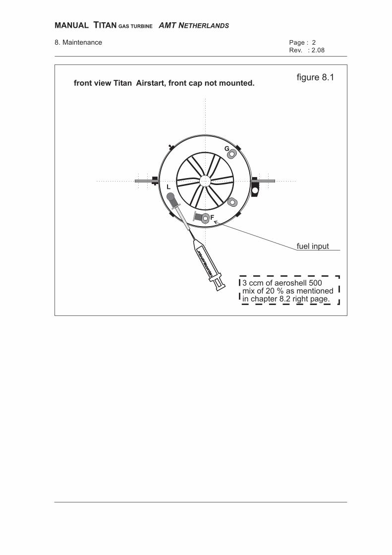
fuel input
3 ccm of aeroshell 500mix of 20 % as mentionedin chapter 8.2 right page.
front view Titan Airstart, front cap not mounted.figure 8.1
8. Maintenance Page : 2
Rev. : 2.08
L
F
G
MANUAL ITANT GAS TURBINE AMT NETHERLANDS
MANUAL TITAN GAS TURBINE AMT NETHERLANDS Page :2 8. Maintenance Revision: 2.09
8.2 Storage and lubrication If the engine will not be used for 3 months or longer we recommend that it has additional lubrication with a mixture of kerosene and 20% Aeroshell 500 oil, as in 8.1 left. This is to prevent any possible corrosion of the ball bearings, which can happen especially if the engine is stored in a humid environment. If the turbine will not be used for longer periods (6 -12 months) it is recommended that it is placed in a vertical position (compressor upward), fuel & gas input and the inlet & exhaust are covered to stop dust and other particles from entering the engine. After this storage period we recommend that you pre-lubricate the engine (as in 8.3) before starting it. 8.3 Removal of Front Cap and pre-lubrication procedure a) Remove the blue Festo Gas input quick-connector useing a 2.5mm hexagon
wrench inserted inside the fitting, the Air start connector uses a 3 mm wrench. Note: It is not possible to remove the Festo quick-connector fitting for the Fuel supply, and if you insert a hexagon wrench into this fitting you may damage it and cause a fuel leak.
b) Loosen 4 of the 5 bolts that hold the hull to the motor by a 1/2 turn. Do not loosen
the bolt that has the lead seal attached, as this may affect the warranty. c) The Front Cap should now be loose, and can be removed by inserting 2 hexagon
wrenches, or similar, in 2 of the holes used for securing it to the motor, and lifting upwards. Be careful not to damage the RPM sensor cable.
d) Remove the short pp4 tube from the Fuel elbow (marked 'F') by pushing the blue
plastic ring part towards the fitting, and pulling the tube out of the Festo fitting. Using a hypodermic syringe and a short length of pp3 tubing, inject 5 or 6 cc of kerosene and 20% Aeroshell 500 turbine oil into the tube connected to the ‘Lube’ fitting.
e) Reconnect the pp4 tube between the Fuel and Lubrication fittings, being careful not to kink or bend it, and replace the Front Cap in the reverse order of removal.
Spin the turbine for about 10 seconds to distribute the oil all around the inside of the turbine. You can do this by connecting a 4.8 or 6 volt DC supply directly to the connector plug of the electric starter. An old 4 or 5 cell receiver battery can be used for this. Do not use more than 6 volts for this process!
Alternatively, if you have compressed air available (8 -12 bar), connect it to the ’Air’ Festo quick connector with pp4 tube and give the motor 2 or 3 short blasts of air to spin the shaft, which will distribute the oil all around the inside of the motor.
Finally place the turbine in a vertical position, compressor upwards, and let any excess oil drain out for 15 minutes before sealing the exhaust with the plastic cap supplied with the turbine.

MANUAL TITAN GAS TURBINE AMT NETHERLANDS Page :3 8. Maintenance Revision: 2.09
8.4 Returning motor for service or repair If you need to return your motor to AMT NL for service or repair please only send the following items, unless other accessories or parts need checking or repair. Please do not send any unnecessary items back to us with the motor, as this will only increase the size and weight of the parcel, which may increase costs. When possible, please use the original packing when returning parts to us for service, to prevent possible damage during shipping. 1. Turbine. Important: Please make sure that the Festo Fuel and Gas input
connections are properly sealed to prevent any dirt getting inside these systems. This can be done with short pieces of tubing with the ends heated with a cigarette lighter and then squashed flat with pliers. Please fit the supplied red plastic caps to the turbine to stop anything getting inside the turbine.
2. ECU. 3. Fuel pump. 4. Either a copy of the Engine Log, showing the problem, or a detailed report on the
problem. Without a clear error description it may take more time to find and solve any problems with your motor.
Note: You may also send the ECU/pump battery back to us with your motor, and we will check that it is still serviceable and has sufficient capacity. If you are sending us an Electric-start version turbine for service, then it is recommended that you send us the battery, as this should be in good condition for proper turbine operation. 8.5 P2 Pressure fitting installation All gastturbines have ready tapped and threaded M5 in the front plate to allow the customer to fit a Festo nipple to provide pressure for a smoke system, topping up your pneumatic retract tank, or similar. If you remove the Front cap, as described in 8.3 for Pre-lubrication, you will see a small s/s grub screw inserted in the Front plate approx. between the Fuel and Air inputs. This plug can be removed with a 2.5mm hexagon wrench, and replaced with a suitable Festo nipple such as the standard CK-M5-PK-3, or a quick-connect type such as the QSM-M5-4-I fitted onto a QM-M5-A/I hexagon extension piece. All new Front Caps manufactured have a small 1mm diameter hole in them placed exactly vertically above this P2 position. Simply drill this out to 8.5mm diameter to allow access to the new P2 pressure nipple. For full details of the smoke system please look on the ‘Download’ page of our website at www.amtjets.com.

MANUAL TITAN GAS TURBINE AMT NETHERLANDS Page :4 8. Maintenance Revision: 2.09
8.6 Looking after your gasturbine These are a few tips from our staff which will help prolong the life of your turbine, and help to prevent some of the small problems that we often see when motors are returned to us for service or repair. 1. Please do not overtighten the 5 bolts that hold the outer casing onto the motor, or
the 5 bolts that retain the Front Cap. It is not necessary to use Loctite, or similar, on any of these bolts.
2. You should occasionally check the RPM sensor to make sure that it is not
touching the compressor wheel. On a Titan the clearance should be about 0.25 - 0.30 mm.
If you replace the RPM sensor because of damage, please follow the instructions we provide with the new sensor, and do not use any loctite or glue on the small M2 bolts that hold the sensor mounting block to the inlet.
3. Please make sure that all tubes and cables, especially the RPM sensor cable
and glow-pug connector cables, are properly secured in front of the motor so that they cannot be sucked into the compressor which will mean that the motor has to be returned to us for repair. This is a common occurence with new operators, who often underestimate the suction of a miniature gasturbine.
4. When connecting pp3-4 tubing into the Festo quick-connect fittings for Fuel, Gas
or Air on the front of your motor (or the internal gas tank), please make sure that the tube is cleanly cut at 90 degrees, and that there are no burrs or dirt on the end of the tube which can easily damage the sealing mechanism inside the Festo fitting. AMT Netherlands can supply customers with the proper Festo tube-cutter for doing this (an inexpensive item), which makes installation and maintenance very simple.
5. Please do not modify the cables, switch, or connectors on the ECU, fuel pump or battery pack in any way. The type and quality of items we supply have been very carefully selected to be suitable for our turbines, and to ensure the highest reliablity and longest life. Also, leaving everything in the ‘standard’ configuration as supplied by AMT NL makes replacement in the event of damage, or maintenance or repair by our staff a simple and more economical task. AMT Netherlands can supply any special extension cables that you need to complete the proper installation in your airplane. Please supply us with accurate lengths when ordering your gasturbine.

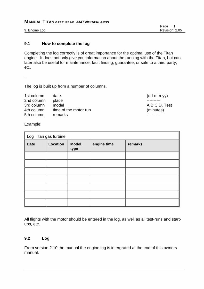
MANUAL TITAN GAS TURBINE AMT NETHERLANDS Page :1 9. Engine Log Revision: 2.05
9.1 How to complete the log Completing the log correctly is of great importance for the optimal use of the Titan engine. It does not only give you information about the running with the Titan, but can later also be useful for maintenance, fault finding, guarantee, or sale to a third party, etc. . The log is built up from a number of columns. 1st column date (dd-mm-yy) 2nd column place ---------- 3rd column model A,B,C,D, Test 4th column time of the motor run (minutes) 5th column remarks ---------- Example:
Log Titan gas turbine
Date Location Model type
engine time remarks
All flights with the motor should be entered in the log, as well as all test-runs and start-ups, etc. 9.2 Log From version 2.10 the manual the engine log is intergrated at the end of this owners manual.

MANUAL TITAN GAS TURBINE AMT NETHERLANDS Page :1 10. Guarantee Revision: 2.04
10.1 Warranty conditions If any shortcomings occur within a period of 24 months after the delivery date, due to material or fabrication defects, these will be compensated free of charge by Advanced Micro Turbines NL, or, if present, by the AMT service centre in your own country. In case of replacement, Advanced Micro Turbines NL becomes the owner of the replaced components. When AMT discovers that the Warranty seals have been broken, or that the ECU or pump or other accessories have been dissassembled or modified in any way, then every form of warranty expires and AMT is in no way responsible for any damage whatsoever. The Warranty does not apply to insufficient maintenance, overloading, natural wastage in case of sale to third-parties and other causes beyond the control of AMT, this within the discretion of AMT Netherlands. 10.2 Completing the warranty card The Warranty card should be completed by the buyer of the turbine, and should be sent by the buyer to AMT within two weeks of receipt. In case of a possible Warranty claim a detailed description of the complaint needs to be sent to AMT, as well as the turbine, ECU, fuel pump and completed Engine Log. Please use the original packaging for this. 10.3 Warranty The Warranty card is included with turbine set.
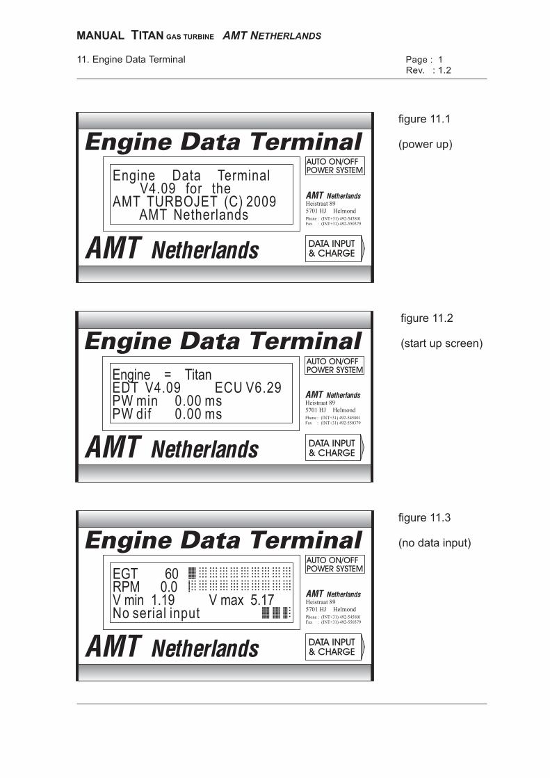
Page : 1
Rev. : 1.211. Engine Data Terminal
PhoneFax
(INT+31) 492-545801(INT+31) 492-550379
::
Heistraat 89
Helmond5701 HJ
Engine Data Terminal
Engine Data TerminalV4.09 for the
AMT TURBOJET (C) 2009AMT Netherlands
figure 11.1
(power up)
figure 11.2
(start up screen)
PhoneFax
(INT+31) 492-545801(INT+31) 492-550379
::
Heistraat 89
Helmond5701 HJ
Engine Data Terminal
EGT 60RPM 0.0V min 1.19 V max 5.17No serial input
figure 11.3
(no data input)
PhoneFax
(INT+31) 492-545801(INT+31) 492-550379
::
Heistraat 89
Helmond5701 HJ
Engine Data Terminal
Engine = TitanEDT V4.09 ECU V6.29PW min 0.00 msPW dif 0.00 ms
MANUAL ITANT GAS TURBINE AMT NETHERLANDS
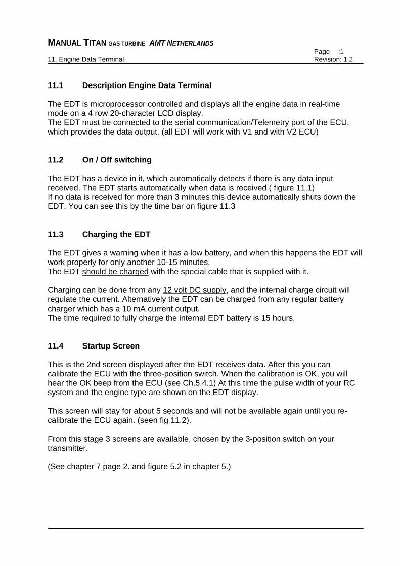
MANUAL TITAN GAS TURBINE AMT NETHERLANDS Page :1 11. Engine Data Terminal Revision: 1.2
11.1 Description Engine Data Terminal The EDT is microprocessor controlled and displays all the engine data in real-time mode on a 4 row 20-character LCD display. The EDT must be connected to the serial communication/Telemetry port of the ECU, which provides the data output. (all EDT will work with V1 and with V2 ECU) 11.2 On / Off switching The EDT has a device in it, which automatically detects if there is any data input received. The EDT starts automatically when data is received.( figure 11.1) If no data is received for more than 3 minutes this device automatically shuts down the EDT. You can see this by the time bar on figure 11.3 11.3 Charging the EDT The EDT gives a warning when it has a low battery, and when this happens the EDT will work properly for only another 10-15 minutes. The EDT should be charged with the special cable that is supplied with it. Charging can be done from any 12 volt DC supply, and the internal charge circuit will regulate the current. Alternatively the EDT can be charged from any regular battery charger which has a 10 mA current output. The time required to fully charge the internal EDT battery is 15 hours. 11.4 Startup Screen This is the 2nd screen displayed after the EDT receives data. After this you can calibrate the ECU with the three-position switch. When the calibration is OK, you will hear the OK beep from the ECU (see Ch.5.4.1) At this time the pulse width of your RC system and the engine type are shown on the EDT display. This screen will stay for about 5 seconds and will not be available again until you re-calibrate the ECU again. (seen fig 11.2). From this stage 3 screens are available, chosen by the 3-position switch on your transmitter. (See chapter 7 page 2. and figure 5.2 in chapter 5.)
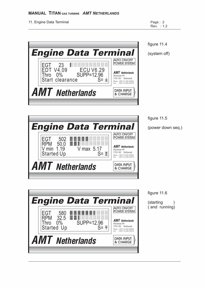
PhoneFax
PhoneFax
PhoneFax
(INT+31) 492-545801(INT+31) 492-550379
(INT+31) 492-545801(INT+31) 492-550379
(INT+31) 492-545801(INT+31) 492-550379
::
::
::
Heistraat 89
Heistraat 89
Heistraat 89
Helmond
Helmond
Helmond
5701 HJ
5701 HJ
5701 HJ
Engine Data Terminal
Engine Data Terminal
Engine Data Terminal
Page : 2
Rev. : 1.211. Engine Data Terminal
EGT 23
EGT 502
EGT 580
EDT V4.09 ECU V6.29
RPM 50.0
RPM 32.5
Thro 0% SUPP=12.96
V min 1.19 V max 5.17
Thro 0% SUPP=12.96
S=
S=
S=
Start clearance
Started Up
Started Up
figure 11.4
(system off)
figure 11.5
(power down seq.)
figure 11.6
(starting )( and running)
MANUAL ITANT GAS TURBINE AMT NETHERLANDS
MANUAL TITAN GAS TURBINE AMT NETHERLANDS Page :2 11. Engine Data Terminal Revision: 1.2
11.5 Screen 1 : "Off" This screen is displayed when the three position switch is in position 1, for "off", indicated by the low beep tone. (figure 11.4) 1st line: Exhaust Gas Temperature in °C (EGT) 2nd line: software version of ECU and software version of EDT 3rd line: throttle position and ECU supply voltage 4th line: additional text and position of the switch channel 11.6 Screen 2 : "Power Down" sequence This screen is displayed when the three-position switch is in position 2, for the "powerdown" sequence, indicated by the middle beep tone. (figure 11.5) 1st line: Exhaust Gas Temperature in °C (EGT) 2nd line: Revolutions of the shaft (RPM) 3rd line: pump voltage at idle and pump voltage at max RPM 4th line: additional text and position of the switch channel 11.7 Screen 3 : "Starting and Running" This screen is displayed when the three-position switch is in position 3, for "starting and running" the engine, indicated by the high beep tone. (figure 11.6) 1st line: Exhaust Gas Temperature in °C (EGT) 2nd line: Revolutions of shaft (RPM) and actual pump voltage (V out) 3rd line: throttle position and ECU supply voltage or additional text 4th line: additional text and position of the switch channel 11.8 Additional Information Line four of every screen gives you additional text when it is required. For example all the error messages are displayed in this line, and also additional information during engine starting. These include messages like "close air" and "close gas ". The text "starting" in line three is a very important message. The message occurs when you are starting up the engine and means that EGT is over 88 °C and RPM has reached 7.000 RPM. Then the fuelpump starts to supply fuel to the engine. When this happens line four gives you information about disconnecting the glowplug, closing the air-valve and gas-bottle. When you use the Version 2 ECU which has the fully automatic electric-start, all these things are done automatically.
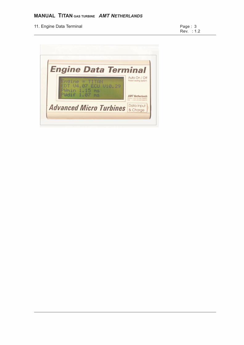
Page : 3
Rev. : 1.211. Engine Data Terminal
MANUAL ITANT GAS TURBINE AMT NETHERLANDS
MANUAL TITAN GAS TURBINE AMT NETHERLANDS Page :3 11. Engine Data Terminal Revision: 1.2
Start clearance -> Engine is ready to start up. Starting -> EGT is over 88 °C and RPM exceeds 7,000 RPM. The fuel pump starts pumping. Started Up -> ECU has successfully started up the engine. Idle RPM set -> Engine has reached idle RPM. Max RPM set -> Engine has reached maximum RPM. Close GAS
-> Engine is starting up, and the engine is running on liquid fuel. If using manual starting, you must now close the valve on the gas bottle.
Close AIR
-> Engine is starting up, the engine is above minimum RPM. If using manual starting, you must now close the air valve.
No start clearance -> Engine is too hot to start (over 88°C). You must cool down the engine before starting. (auto cool function, switch middle position) -> When you are using the the V2 fully automatic E-start ECU, this message occurs, there is no proper working glowplug connected. -> When you are using the Automatic Startup Unit and this message occurs, there is no proper working glowplug connected. 11.9 Error messages As mentioned in 11.8, line four of the EDT gives also possible error messages. These messages are very important for trouble shooting. EDT errors - EDT low battery = EDT battery voltage is below 6.3 volt. -> charge EDT. - no serial input. = ECU is sending no data to EDT. -> switch on ECU.

MANUAL ITANT GAS TURBINE AMT NETHERLANDS
MANUAL TITAN GAS TURBINE AMT NETHERLANDS Page :4 11. Engine Data Terminal Revision: 1.2
ECU errors - Supply low error = ECU battery voltage became below 12.0 volt during running. = ECU battery voltage is below 14.8 volt at startup. -> charge ECU battery. (AMT advises to charge batteries before every flight.) - Switch fail = no switch channel connected. -> Check that receiver is switched on ? -> Check that switch channel is connected ? -> Check wireing. - Throttle fail = no throttle channel connected. -> Check that receiver is switched on ? -> Check that throttle channel is connected ? -> Check wireing. Engine errors - RPM low error = engine RPM below 25,000 RPM. -> check fuel system, possible air in the system. - RPM high error = engine RPM over 101,000 RPM. -> check fuel system, possible dirt in the system. -> possible bent fuel line. -> possible fuel pump problem. - EGT error = EGT over 850 °C at startup. > check position of thermo sensor in nozzle (maybe too far in?). (fig 6.7) > possible inlet duct problem. (not enough air to motor) > possible fuel system problem. (dirt) *** Important *** When you have an engine shut off because of an error, connect the EDT to the ECU. Then the EDT gives you the error type. After you have switched off the ECU the error message is no longer available.

Engine logEngine log
copyright Advanced Micro Turbines

©
model : A model : B model : C model : D
date location model engine time remarks
- - min.
- - min.
- - min.
- - min.
- - min.
- - min.
- - min.
- - min.
- - min.
- - min.
- - min.
- - min.
- - min.
- - min.
- - min.
- - min.
- - min.
- - min.
- - min.
- - min.
- - min.
- - min.
- - min.
motor test = T
Advanced Micro Turbines
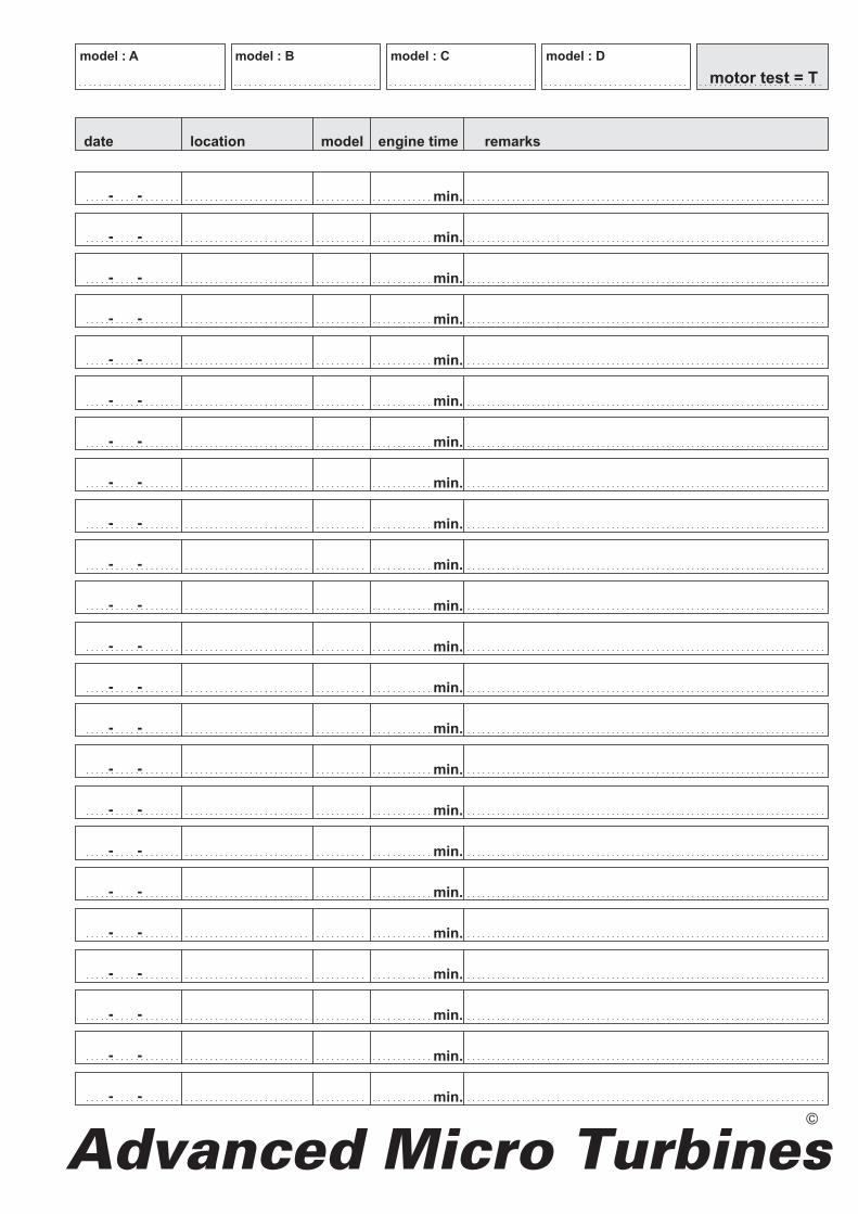
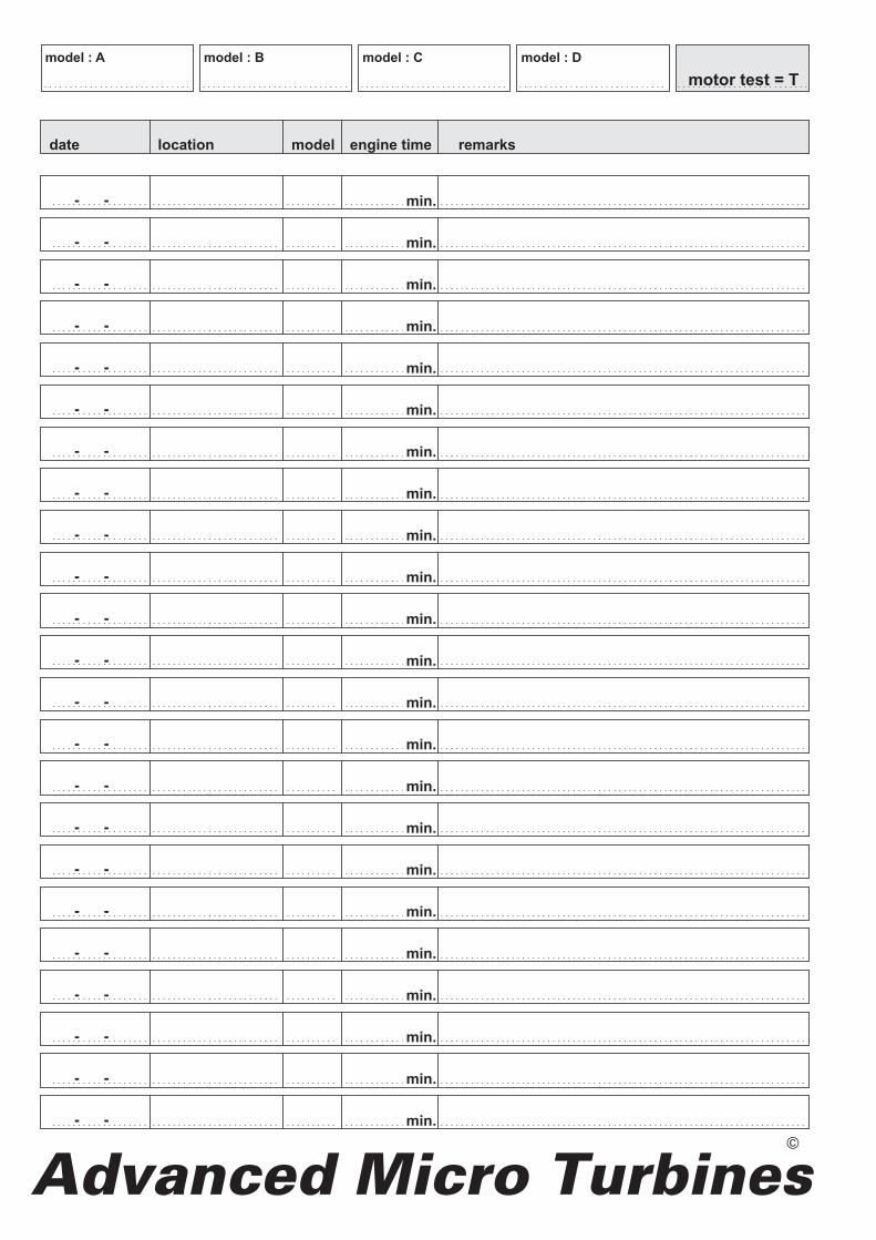

MANUAL Titan Advanced Micro Turbines