Tips for Using the EDMA with the Utopia Port
24
Application Report SPRA952 - September 2003 1 Tips for Using the EDMA With the UTOPIA Port Kimberly Daniel Digital Signal Processing Solutions ABSTRACT Typically, the EDMA services the UTOPIA interface by writing data to the slave transmit queue (UXQ) and reading data from the slave receive queue (URQ). This document discusses the proper way to configure the EDMA to interface with the UTOPIA port by: • Describing the EDMA configuration required to complete a 2D, array synchronized transfer to UTOPIA. • Giving three possible solutions to the problem of beginning an EDMA transfer to UTOPIA after linking to the null parameter set. Contents 1 Overview of UTOPIA 2 . . . . . . . . . . . . . . . . . . . . . . . . . . . . . . . . . . . . . . . . . . . . . . . . . . . . . . . . . . . . . . . . . 1.1 UTOPIA Signal Descriptions 2 . . . . . . . . . . . . . . . . . . . . . . . . . . . . . . . . . . . . . . . . . . . . . . . . . . . . . . . 1.2 UTOPIA Registers 4 . . . . . . . . . . . . . . . . . . . . . . . . . . . . . . . . . . . . . . . . . . . . . . . . . . . . . . . . . . . . . . . . 2 EDMA-UTOPIA Interface 6 . . . . . . . . . . . . . . . . . . . . . . . . . . . . . . . . . . . . . . . . . . . . . . . . . . . . . . . . . . . . . . 2.1 Basic Example 6 . . . . . . . . . . . . . . . . . . . . . . . . . . . . . . . . . . . . . . . . . . . . . . . . . . . . . . . . . . . . . . . . . . . 2.1.1 EDMA Setup for UTOPIA Transmitter 6 . . . . . . . . . . . . . . . . . . . . . . . . . . . . . . . . . . . . . . . . . 2.1.2 EDMA Setup for UTOPIA Receiver 9 . . . . . . . . . . . . . . . . . . . . . . . . . . . . . . . . . . . . . . . . . . . 2.2 Beginning an EDMA Transfer After Linking to Null 12 . . . . . . . . . . . . . . . . . . . . . . . . . . . . . . . . . . . 2.2.1 Probem Description 12 . . . . . . . . . . . . . . . . . . . . . . . . . . . . . . . . . . . . . . . . . . . . . . . . . . . . . . . 2.2.2 Solution #1: Do not LINK to NULL 12 . . . . . . . . . . . . . . . . . . . . . . . . . . . . . . . . . . . . . . . . . . . 2.2.3 Solution #2: Setting the Event Set Regsiter (ESR) 13 . . . . . . . . . . . . . . . . . . . . . . . . . . . . . 2.2.4 Solution #3: Reset UTOPIA 14 . . . . . . . . . . . . . . . . . . . . . . . . . . . . . . . . . . . . . . . . . . . . . . . . Appendix A Title 16 . . . . . . . . . . . . . . . . . . . . . . . . . . . . . . . . . . . . . . . . . . . . . . . . . . . . . . . . . . . . . . . . . . . . . . . List of Figures Figure 1 UTOPIA Block Diagram 2 . . . . . . . . . . . . . . . . . . . . . . . . . . . . . . . . . . . . . . . . . . . . . . . . . . . . . . . . Figure 2 UTOPIA Control Register (UCR) 5 . . . . . . . . . . . . . . . . . . . . . . . . . . . . . . . . . . . . . . . . . . . . . . . . Figure 3 Parameter Storage for an EDMA Event 7 . . . . . . . . . . . . . . . . . . . . . . . . . . . . . . . . . . . . . . . . . . Figure 4 Array-Synchronized 2-D to 1-D Transfer 8 . . . . . . . . . . . . . . . . . . . . . . . . . . . . . . . . . . . . . . . . . Figure 5 Array-Synchronized 1-D to 2-D transfer 11 . . . . . . . . . . . . . . . . . . . . . . . . . . . . . . . . . . . . . . . . . Figure 6 EDMA Parameters for Ping-Pong Buffering 13 . . . . . . . . . . . . . . . . . . . . . . . . . . . . . . . . . . . . . . Trademarks are the property of their respective owners.
Transcript of Tips for Using the EDMA with the Utopia Port
Application ReportSPRA952 - September 2003
1
Tips for Using the EDMA With the UTOPIA PortKimberly Daniel Digital Signal Processing Solutions
ABSTRACT
Typically, the EDMA services the UTOPIA interface by writing data to the slave transmitqueue (UXQ) and reading data from the slave receive queue (URQ). This documentdiscusses the proper way to configure the EDMA to interface with the UTOPIA port by:
• Describing the EDMA configuration required to complete a 2D, array synchronized transferto UTOPIA.
• Giving three possible solutions to the problem of beginning an EDMA transfer to UTOPIAafter linking to the null parameter set.
Contents
1 Overview of UTOPIA 2. . . . . . . . . . . . . . . . . . . . . . . . . . . . . . . . . . . . . . . . . . . . . . . . . . . . . . . . . . . . . . . . . 1.1 UTOPIA Signal Descriptions 2. . . . . . . . . . . . . . . . . . . . . . . . . . . . . . . . . . . . . . . . . . . . . . . . . . . . . . . 1.2 UTOPIA Registers 4. . . . . . . . . . . . . . . . . . . . . . . . . . . . . . . . . . . . . . . . . . . . . . . . . . . . . . . . . . . . . . . .
2 EDMA-UTOPIA Interface 6. . . . . . . . . . . . . . . . . . . . . . . . . . . . . . . . . . . . . . . . . . . . . . . . . . . . . . . . . . . . . . 2.1 Basic Example 6. . . . . . . . . . . . . . . . . . . . . . . . . . . . . . . . . . . . . . . . . . . . . . . . . . . . . . . . . . . . . . . . . . .
2.1.1 EDMA Setup for UTOPIA Transmitter 6. . . . . . . . . . . . . . . . . . . . . . . . . . . . . . . . . . . . . . . . . 2.1.2 EDMA Setup for UTOPIA Receiver 9. . . . . . . . . . . . . . . . . . . . . . . . . . . . . . . . . . . . . . . . . . .
2.2 Beginning an EDMA Transfer After Linking to Null 12. . . . . . . . . . . . . . . . . . . . . . . . . . . . . . . . . . . 2.2.1 Probem Description 12. . . . . . . . . . . . . . . . . . . . . . . . . . . . . . . . . . . . . . . . . . . . . . . . . . . . . . . 2.2.2 Solution #1: Do not LINK to NULL 12. . . . . . . . . . . . . . . . . . . . . . . . . . . . . . . . . . . . . . . . . . . 2.2.3 Solution #2: Setting the Event Set Regsiter (ESR) 13. . . . . . . . . . . . . . . . . . . . . . . . . . . . . 2.2.4 Solution #3: Reset UTOPIA 14. . . . . . . . . . . . . . . . . . . . . . . . . . . . . . . . . . . . . . . . . . . . . . . .
Appendix A Title 16. . . . . . . . . . . . . . . . . . . . . . . . . . . . . . . . . . . . . . . . . . . . . . . . . . . . . . . . . . . . . . . . . . . . . . .
List of Figures
Figure 1 UTOPIA Block Diagram 2. . . . . . . . . . . . . . . . . . . . . . . . . . . . . . . . . . . . . . . . . . . . . . . . . . . . . . . . Figure 2 UTOPIA Control Register (UCR) 5. . . . . . . . . . . . . . . . . . . . . . . . . . . . . . . . . . . . . . . . . . . . . . . . Figure 3 Parameter Storage for an EDMA Event 7. . . . . . . . . . . . . . . . . . . . . . . . . . . . . . . . . . . . . . . . . . Figure 4 Array-Synchronized 2-D to 1-D Transfer 8. . . . . . . . . . . . . . . . . . . . . . . . . . . . . . . . . . . . . . . . . Figure 5 Array-Synchronized 1-D to 2-D transfer 11. . . . . . . . . . . . . . . . . . . . . . . . . . . . . . . . . . . . . . . . . Figure 6 EDMA Parameters for Ping-Pong Buffering 13. . . . . . . . . . . . . . . . . . . . . . . . . . . . . . . . . . . . . .
Trademarks are the property of their respective owners.
SPRA952
2 Tips for Using the EDMA With the UTOPIA Port
List of Tables
Table 1 Slave UTOPIA Pin Description 3. . . . . . . . . . . . . . . . . . . . . . . . . . . . . . . . . . . . . . . . . . . . . . . . .
Table 2 UTOPIA Data Port address 4. . . . . . . . . . . . . . . . . . . . . . . . . . . . . . . . . . . . . . . . . . . . . . . . . . . . .
Table 3 UTOPIA Configuration Register 4. . . . . . . . . . . . . . . . . . . . . . . . . . . . . . . . . . . . . . . . . . . . . . . .
Table 4 UTOPIA Control Register (UCR) Bit Field Description 5. . . . . . . . . . . . . . . . . . . . . . . . . . . . .
Table 5 EDMA Synchronization Events from UTOPIA 6. . . . . . . . . . . . . . . . . . . . . . . . . . . . . . . . . . . . .
1 Overview of UTOPIA
The C64x UTOPIA peripheral is an ATM controller (ATMC) slave device that interfaces to amaster ATM controller. The UTOPIA port conforms to the ATM Forum standard specificationaf-phy-0039.000. Specifically, this interface supports the UTOPIA Level 2 interface that allows8-bit slave operation up to 50 MHz for both transmit and receive operations.
All references to the term “slave devices” are analogous to multi-PHYs (MPHYs) as referencedin the ATM Forum specification. Only cell-level handshaking is supported.
The UTOPIA peripheral supports the standard ATM cell format of 53 bytes (5-byte header +48-byte payload), as well as, a non-standard ATM cell of size 54 to 64 bytes.
1.1 UTOPIA Signal Descriptions
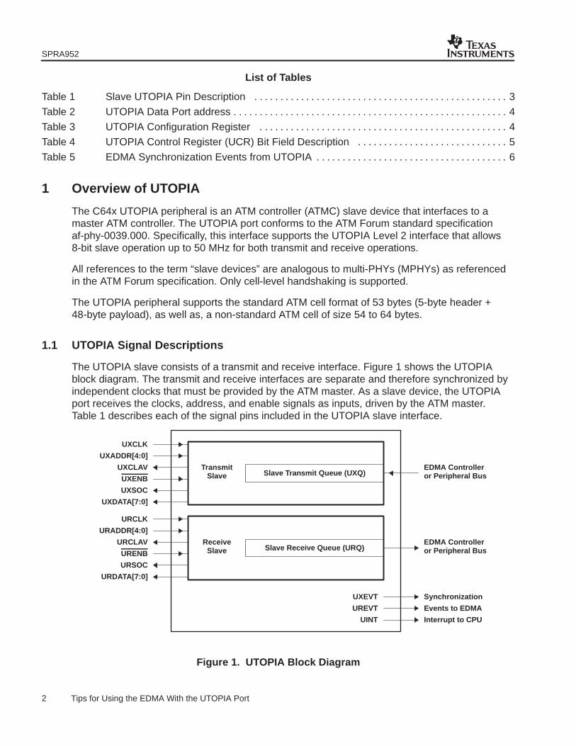
The UTOPIA slave consists of a transmit and receive interface. Figure 1 shows the UTOPIAblock diagram. The transmit and receive interfaces are separate and therefore synchronized byindependent clocks that must be provided by the ATM master. As a slave device, the UTOPIAport receives the clocks, address, and enable signals as inputs, driven by the ATM master.Table 1 describes each of the signal pins included in the UTOPIA slave interface.
Slave Transmit Queue (UXQ)Transmit
Slave
UXCLK
UXADDR[4:0]
UXCLAV
UXENB
UXSOC
UXDATA[7:0]
EDMA Controlleror Peripheral Bus
or Peripheral BusEDMA ControllerURCLAV
URDATA[7:0]
URSOC
URENB
URADDR[4:0]
URCLK
Slave Receive Queue (URQ)Receive
Slave
UXEVT
UREVT
UINT
Synchronization
Events to EDMA
Interrupt to CPU
Figure 1. UTOPIA Block Diagram
SPRA952
3 Tips for Using the EDMA With the UTOPIA Port
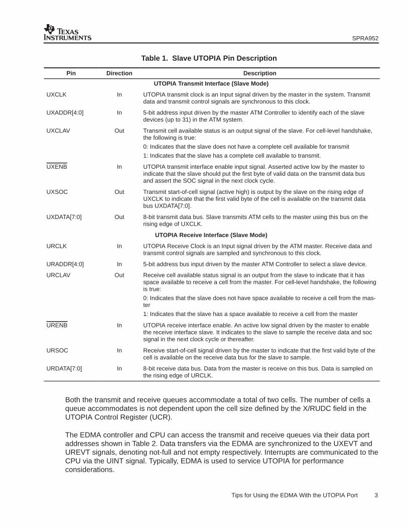
Table 1. Slave UTOPIA Pin Description
Pin Direction Description
UTOPIA Transmit Interface (Slave Mode)
UXCLK In UTOPIA transmit clock is an Input signal driven by the master in the system. Transmitdata and transmit control signals are synchronous to this clock.
UXADDR[4:0] In 5-bit address input driven by the master ATM Controller to identify each of the slavedevices (up to 31) in the ATM system.
UXCLAV Out Transmit cell available status is an output signal of the slave. For cell-level handshake,the following is true:
0: Indicates that the slave does not have a complete cell available for transmit
1: Indicates that the slave has a complete cell available to transmit.
UXENB In UTOPIA transmit interface enable input signal. Asserted active low by the master toindicate that the slave should put the first byte of valid data on the transmit data busand assert the SOC signal in the next clock cycle.
UXSOC Out Transmit start-of-cell signal (active high) is output by the slave on the rising edge ofUXCLK to indicate that the first valid byte of the cell is available on the transmit databus UXDATA[7:0].
UXDATA[7:0] Out 8-bit transmit data bus. Slave transmits ATM cells to the master using this bus on therising edge of UXCLK.
UTOPIA Receive Interface (Slave Mode)
URCLK In UTOPIA Receive Clock is an Input signal driven by the ATM master. Receive data andtransmit control signals are sampled and synchronous to this clock.
URADDR[4:0] In 5-bit address bus input driven by the master ATM Controller to select a slave device.
URCLAV Out Receive cell available status signal is an output from the slave to indicate that it hasspace available to receive a cell from the master. For cell-level handshake, the followingis true:
0: Indicates that the slave does not have space available to receive a cell from the mas-ter
1: Indicates that the slave has a space available to receive a cell from the master
URENB In UTOPIA receive interface enable. An active low signal driven by the master to enablethe receive interface slave. It indicates to the slave to sample the receive data and socsignal in the next clock cycle or thereafter.
URSOC In Receive start-of-cell signal driven by the master to indicate that the first valid byte of thecell is available on the receive data bus for the slave to sample.
URDATA[7:0] In 8-bit receive data bus. Data from the master is receive on this bus. Data is sampled onthe rising edge of URCLK.
Both the transmit and receive queues accommodate a total of two cells. The number of cells aqueue accommodates is not dependent upon the cell size defined by the X/RUDC field in theUTOPIA Control Register (UCR).
The EDMA controller and CPU can access the transmit and receive queues via their data portaddresses shown in Table 2. Data transfers via the EDMA are synchronized to the UXEVT andUREVT signals, denoting not-full and not empty respectively. Interrupts are communicated to theCPU via the UINT signal. Typically, EDMA is used to service UTOPIA for performanceconsiderations.

SPRA952
4 Tips for Using the EDMA With the UTOPIA Port
Table 2. UTOPIA Data Port address
Acronym Queue Name Address
URQ UTOPIA Receive Queue 3C00 0000h
UXQ UTOPIA Transmit Queue 3D00 0000h
1.2 UTOPIA Registers
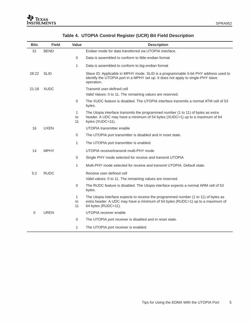
The UTOPIA port is configured via the configuration registers listed in Table 3. The UTOPIAControl Register (UCR) contains UTOPIA status control bits. The UCR is shown in Figure 2 andsummarized in Table 4. The ATM master can configure the slave’s address (SLID field) in theUCR through the HPI/PCI or McBSP interface.
Table 3. UTOPIA Configuration Register
Acronym Queue Name Address
UCR UTOPIA Control Register 01B4 0000h
− Reserved 01B4 0004h
− Reserved 01B4 0008h
UIER UTOPIA Interrupt Enable Register 01B4 000Ch
UIPR UTOPIA Interrupt Pending Register 01B4 0010h
CDR Clock Detect Register 01B4 0014h
EIER Error Interrupt Enable Register 01B4 0018h
EIPR Error Interrupt Pending Register 01B4 001Ch
31 30 29 28 24 23 22 21 18 17 16
BEND Rsvd SLID Rsvd XUDC Rsvd UXEN
RW,+0 R,+0 RW,+0 R,+0 RW,+0 R,+0 RW,+0
15 14 13 6 5 2 1 0
Rsvd MPHY Rsvd RUDC Rsvd UREN
R,+0 RW,+1 R,+0 RW,+0 R,+0 RW,+0
Figure 2. UTOPIA Control Register (UCR)
SPRA952
5 Tips for Using the EDMA With the UTOPIA Port
Table 4. UTOPIA Control Register (UCR) Bit Field Description
Bits Field Value Description
31 BEND Endian mode for data transferred via UTOPIA interface.
0 Data is assembled to conform to little-endian format
1 Data is assembled to conform to big-endian format
28:22 SLID Slave ID: Applicable in MPHY mode. SLID is a programmable 5-bit PHY address used toidentify the UTOPIA port in a MPHY set up. It does not apply to single-PHY slaveoperation.
21:18 XUDC Transmit user-defined cell
Valid Values: 0 to 11. The remaining values are reserved.
0 The XUDC feature is disabled. The UTOPIA interface transmits a normal ATM cell of 53bytes.
1to11
The Utopia interface transmits the programmed number (1 to 11) of bytes as extraheader. A UDC may have a minimum of 54 bytes (XUDC=1) up to a maximum of 64bytes (XUDC=11).
16 UXEN UTOPIA transmitter enable
0 The UTOPIA port transmitter is disabled and in reset state.
1 The UTOPIA port transmitter is enabled.
14 MPHY UTOPIA receive/transmit multi-PHY mode
0 Single PHY mode selected for receive and transmit UTOPIA
1 Multi-PHY mode selected for receive and transmit UTOPIA. Default state.
5:2 RUDC Receive user-defined cell
Valid values: 0 to 11. The remaining values are reserved.
0 The RUDC feature is disabled. The Utopia interface expects a normal ARM cell of 53bytes.
1to11
The Utopia interface expects to receive the programmed number (1 to 11) of bytes asextra header. A UDC may have a minimum of 54 bytes (RUDC=1) up to a maximum of64 bytes (RUDC=11).
0 UREN UTOPIA receiver enable
0 The UTOPIA port receiver is disabled and in reset state.
1 The UTOPIA port receiver is enabled.
SPRA952
6 Tips for Using the EDMA With the UTOPIA Port
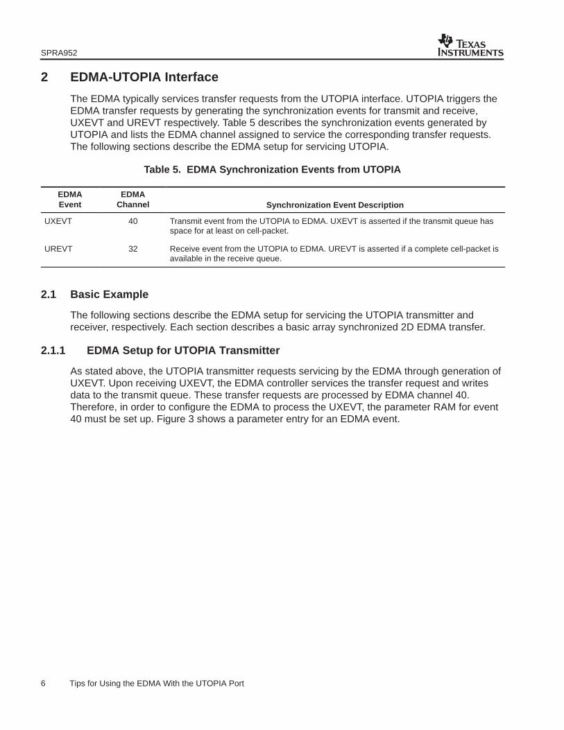
2 EDMA-UTOPIA Interface
The EDMA typically services transfer requests from the UTOPIA interface. UTOPIA triggers theEDMA transfer requests by generating the synchronization events for transmit and receive,UXEVT and UREVT respectively. Table 5 describes the synchronization events generated byUTOPIA and lists the EDMA channel assigned to service the corresponding transfer requests.The following sections describe the EDMA setup for servicing UTOPIA.
Table 5. EDMA Synchronization Events from UTOPIA
EDMAEvent
EDMAChannel Synchronization Event Description
UXEVT 40 Transmit event from the UTOPIA to EDMA. UXEVT is asserted if the transmit queue hasspace for at least on cell-packet.
UREVT 32 Receive event from the UTOPIA to EDMA. UREVT is asserted if a complete cell-packet isavailable in the receive queue.
2.1 Basic Example
The following sections describe the EDMA setup for servicing the UTOPIA transmitter andreceiver, respectively. Each section describes a basic array synchronized 2D EDMA transfer.
2.1.1 EDMA Setup for UTOPIA Transmitter
As stated above, the UTOPIA transmitter requests servicing by the EDMA through generation ofUXEVT. Upon receiving UXEVT, the EDMA controller services the transfer request and writesdata to the transmit queue. These transfer requests are processed by EDMA channel 40.Therefore, in order to configure the EDMA to process the UXEVT, the parameter RAM for event40 must be set up. Figure 3 shows a parameter entry for an EDMA event.
SPRA952
7 Tips for Using the EDMA With the UTOPIA Port
Options (OPT)
SRC Address(SRC)
Array/frame count (FRMCNT) Element count(ELECNT)
DST address(DST)
Array/frame index(FRMIDX) Element index(ELEIDX)
Element count reload(ELERLD) Link address (LINK)
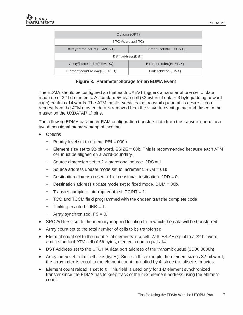
Figure 3. Parameter Storage for an EDMA Event
The EDMA should be configured so that each UXEVT triggers a transfer of one cell of data,made up of 32-bit elements. A standard 56 byte cell (53 bytes of data + 3 byte padding to wordalign) contains 14 words. The ATM master services the transmit queue at its desire. Uponrequest from the ATM master, data is removed from the slave transmit queue and driven to themaster on the UXDATA[7:0] pins.
The following EDMA parameter RAM configuration transfers data from the transmit queue to atwo dimensional memory mapped location.
• Options
− Priority level set to urgent. PRI = 000b.
− Element size set to 32-bit word. ESIZE = 00b. This is recommended because each ATMcell must be aligned on a word-boundary.
− Source dimension set to 2-dimensional source. 2DS = 1.
− Source address update mode set to increment. SUM = 01b.
− Destination dimension set to 1-dimensional destination. 2DD = 0.
− Destination address update mode set to fixed mode. DUM = 00b.
− Transfer complete interrupt enabled. TCINT = 1.
− TCC and TCCM field programmed with the chosen transfer complete code.
− Linking enabled. LINK = 1.
− Array synchronized. FS = 0.
• SRC Address set to the memory mapped location from which the data will be transferred.
• Array count set to the total number of cells to be transferred.
• Element count set to the number of elements in a cell. With ESIZE equal to a 32-bit wordand a standard ATM cell of 56 bytes, element count equals 14.
• DST Address set to the UTOPIA data port address of the transmit queue (3D00 0000h).
• Array index set to the cell size (bytes). Since in this example the element size is 32-bit word,the array index is equal to the element count multiplied by 4, since the offset is in bytes.
• Element count reload is set to 0. This field is used only for 1-D element synchronizedtransfer since the EDMA has to keep track of the next element address using the elementcount.
SPRA952
8 Tips for Using the EDMA With the UTOPIA Port
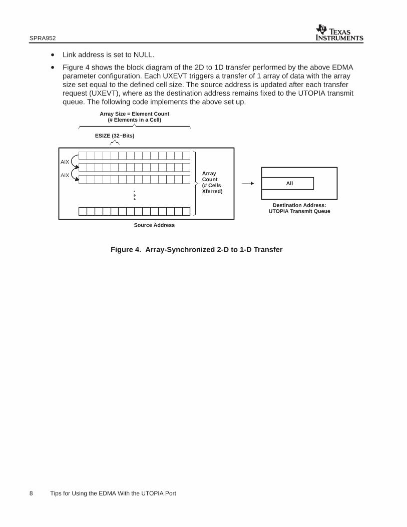
• Link address is set to NULL.
• Figure 4 shows the block diagram of the 2D to 1D transfer performed by the above EDMAparameter configuration. Each UXEVT triggers a transfer of 1 array of data with the arraysize set equal to the defined cell size. The source address is updated after each transferrequest (UXEVT), where as the destination address remains fixed to the UTOPIA transmitqueue. The following code implements the above set up.
ESIZE (32−Bits)
Array Size = Element Count(# Elements in a Cell)
ArrayCount(# CellsXferred)
All
Source Address
Destination Address:UTOPIA Transmit Queue
AIX
AIX
Figure 4. Array-Synchronized 2-D to 1-D Transfer
SPRA952
9 Tips for Using the EDMA With the UTOPIA Port
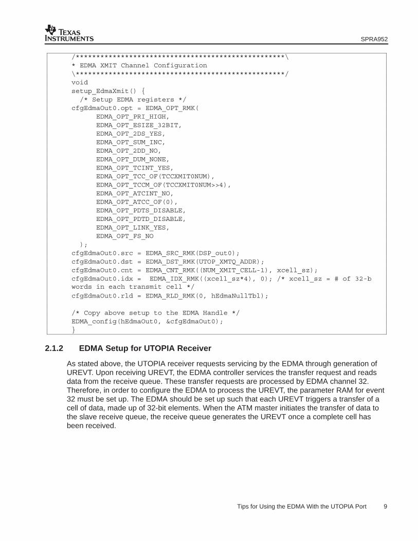
/***************************************************\* EDMA XMIT Channel Configuration\***************************************************/voidsetup_EdmaXmit() { /* Setup EDMA registers */cfgEdmaOut0.opt = EDMA_OPT_RMK(
EDMA_OPT_PRI_HIGH,EDMA_OPT_ESIZE_32BIT,EDMA_OPT_2DS_YES,EDMA_OPT_SUM_INC,EDMA_OPT_2DD_NO,EDMA_OPT_DUM_NONE,EDMA_OPT_TCINT_YES,EDMA_OPT_TCC_OF(TCCXMIT0NUM),EDMA_OPT_TCCM_OF(TCCXMIT0NUM>>4),EDMA_OPT_ATCINT_NO,EDMA_OPT_ATCC_OF(0),EDMA_OPT_PDTS_DISABLE,EDMA_OPT_PDTD_DISABLE,EDMA_OPT_LINK_YES,EDMA_OPT_FS_NO
);cfgEdmaOut0.src = EDMA_SRC_RMK(DSP_out0);cfgEdmaOut0.dst = EDMA_DST_RMK(UTOP_XMTQ_ADDR);cfgEdmaOut0.cnt = EDMA_CNT_RMK((NUM_XMIT_CELL-1), xcell_sz);cfgEdmaOut0.idx = EDMA_IDX_RMK((xcell_sz*4), 0); /* xcell_sz = # of 32-bwords in each transmit cell */
cfgEdmaOut0.rld = EDMA_RLD_RMK(0, hEdmaNullTbl);
/* Copy above setup to the EDMA Handle */EDMA_config(hEdmaOut0, &cfgEdmaOut0);}
2.1.2 EDMA Setup for UTOPIA Receiver
As stated above, the UTOPIA receiver requests servicing by the EDMA through generation ofUREVT. Upon receiving UREVT, the EDMA controller services the transfer request and readsdata from the receive queue. These transfer requests are processed by EDMA channel 32.Therefore, in order to configure the EDMA to process the UREVT, the parameter RAM for event32 must be set up. The EDMA should be set up such that each UREVT triggers a transfer of acell of data, made up of 32-bit elements. When the ATM master initiates the transfer of data tothe slave receive queue, the receive queue generates the UREVT once a complete cell hasbeen received.
SPRA952
10 Tips for Using the EDMA With the UTOPIA Port
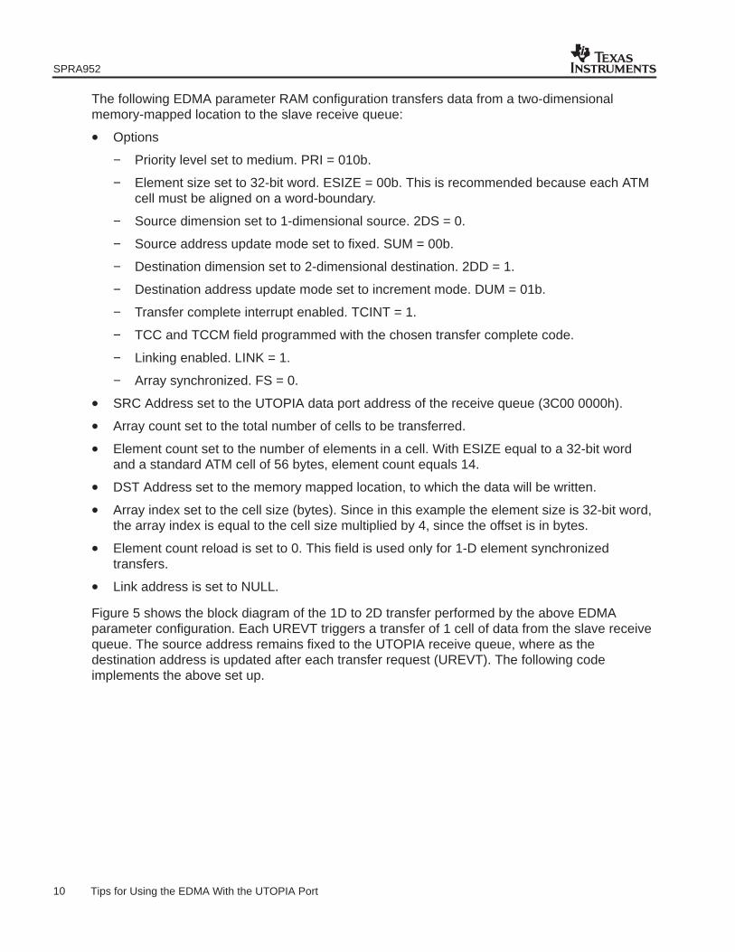
The following EDMA parameter RAM configuration transfers data from a two-dimensionalmemory-mapped location to the slave receive queue:
• Options
− Priority level set to medium. PRI = 010b.
− Element size set to 32-bit word. ESIZE = 00b. This is recommended because each ATMcell must be aligned on a word-boundary.
− Source dimension set to 1-dimensional source. 2DS = 0.
− Source address update mode set to fixed. SUM = 00b.
− Destination dimension set to 2-dimensional destination. 2DD = 1.
− Destination address update mode set to increment mode. DUM = 01b.
− Transfer complete interrupt enabled. TCINT = 1.
− TCC and TCCM field programmed with the chosen transfer complete code.
− Linking enabled. LINK = 1.
− Array synchronized. FS = 0.
• SRC Address set to the UTOPIA data port address of the receive queue (3C00 0000h).
• Array count set to the total number of cells to be transferred.
• Element count set to the number of elements in a cell. With ESIZE equal to a 32-bit wordand a standard ATM cell of 56 bytes, element count equals 14.
• DST Address set to the memory mapped location, to which the data will be written.
• Array index set to the cell size (bytes). Since in this example the element size is 32-bit word,the array index is equal to the cell size multiplied by 4, since the offset is in bytes.
• Element count reload is set to 0. This field is used only for 1-D element synchronizedtransfers.
• Link address is set to NULL.
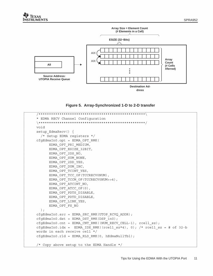
Figure 5 shows the block diagram of the 1D to 2D transfer performed by the above EDMAparameter configuration. Each UREVT triggers a transfer of 1 cell of data from the slave receivequeue. The source address remains fixed to the UTOPIA receive queue, where as thedestination address is updated after each transfer request (UREVT). The following codeimplements the above set up.
SPRA952
11 Tips for Using the EDMA With the UTOPIA Port
ESIZE (32−Bits)
Array Size = Element Count(# Elements in a Cell)
ArrayCount(# CellsXferred)
All
Destination Ad-dress
Source Address:UTOPIA Receive Queue
AIX
AIX
Figure 5. Array-Synchronized 1-D to 2-D transfer
/***************************************************\* EDMA RECV Channel Configuration\***************************************************/voidsetup_EdmaRecv() { /* Setup EDMA registers */cfgEdmaIn0.opt = EDMA_OPT_RMK(
EDMA_OPT_PRI_MEDIUM,EDMA_OPT_ESIZE_32BIT,EDMA_OPT_2DS_NO,EDMA_OPT_SUM_NONE,EDMA_OPT_2DD_YES,EDMA_OPT_DUM_INC,EDMA_OPT_TCINT_YES,EDMA_OPT_TCC_OF(TCCRECV0NUM),EDMA_OPT_TCCM_OF(TCCRECV0NUM>>4),EDMA_OPT_ATCINT_NO,EDMA_OPT_ATCC_OF(0),EDMA_OPT_PDTS_DISABLE,EDMA_OPT_PDTD_DISABLE,EDMA_OPT_LINK_YES,EDMA_OPT_FS_NO
);cfgEdmaIn0.src = EDMA_SRC_RMK(UTOP_RCVQ_ADDR);cfgEdmaIn0.dst = EDMA_DST_RMK(DSP_in0);cfgEdmaIn0.cnt = EDMA_CNT_RMK((NUM_RECV_CELL-1), rcell_sz);cfgEdmaIn0.idx = EDMA_IDX_RMK((rcell_sz*4), 0); /* rcell_sz = # of 32-bwords in each receive cell */
cfgEdmaIn0.rld = EDMA_RLD_RMK(0, hEdmaNullTbl); /* Copy above setup to the EDMA Handle */
SPRA952
12 Tips for Using the EDMA With the UTOPIA Port
EDMA_config(hEdmaIn0, &cfgEdmaIn0);}
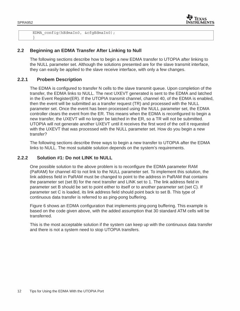
2.2 Beginning an EDMA Transfer After Linking to Null
The following sections describe how to begin a new EDMA transfer to UTOPIA after linking tothe NULL parameter set. Although the solutions presented are for the slave transmit interface,they can easily be applied to the slave receive interface, with only a few changes.
2.2.1 Probem Description
The EDMA is configured to transfer N cells to the slave transmit queue. Upon completion of thetransfer, the EDMA links to NULL. The next UXEVT generated is sent to the EDMA and latchedin the Event Register(ER). If the UTOPIA transmit channel, channel 40, of the EDMA is enabled,then the event will be submitted as a transfer request (TR) and processed with the NULLparameter set. Once the event has been processed using the NULL parameter set, the EDMAcontroller clears the event from the ER. This means when the EDMA is reconfigured to begin anew transfer, the UXEVT will no longer be latched in the ER, so a TR will not be submitted.UTOPIA will not generate another UXEVT until it receives the first word of the cell it requestedwith the UXEVT that was processed with the NULL parameter set. How do you begin a newtransfer?
The following sections describe three ways to begin a new transfer to UTOPIA after the EDMAlinks to NULL. The most suitable solution depends on the system’s requirements.
2.2.2 Solution #1: Do not LINK to NULL
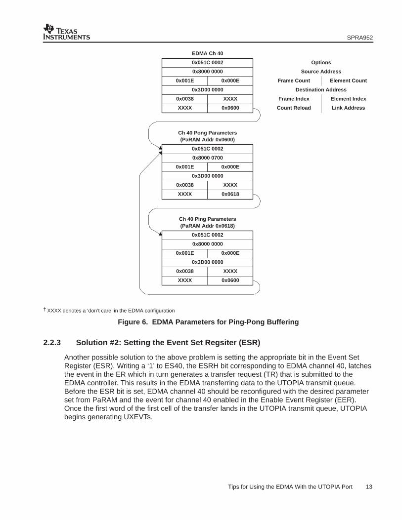
One possible solution to the above problem is to reconfigure the EDMA parameter RAM(PaRAM) for channel 40 to not link to the NULL parameter set. To implement this solution, thelink address field in PaRAM must be changed to point to the address in PaRAM that containsthe parameter set (set B) for the next transfer and LINK set to 1. The link address field inparameter set B should be set to point either to itself or to another parameter set (set C). Ifparameter set C is loaded, its link address field should point back to set B. This type ofcontinuous data transfer is referred to as ping-pong buffering.
Figure 6 shows an EDMA configuration that implements ping-pong buffering. This example isbased on the code given above, with the added assumption that 30 standard ATM cells will betransferred.
This is the most acceptable solution if the system can keep up with the continuous data transferand there is not a system need to stop UTOPIA transfers.
SPRA952
13 Tips for Using the EDMA With the UTOPIA Port
0x001E 0x000E
0x8000 0000
0x051C 0002
0x3D00 0000
0x0038 XXXX
XXXX 0x0600
EDMA Ch 40
XXXX
0x0038
0x001E
XXXX
0x0618
0x3D00 0000
0x8000 0700
0x000E
Ch 40 Pong Parameters
0x051C 0002
(PaRAM Addr 0x0600)
0x3D00 0000
XXXX
0x0600
Ch 40 Ping Parameters(PaRAM Addr 0x0618)
0x8000 0000
0x051C 0002
0x000E0x001E
0x0038
XXXX
Options
Source Address
Destination Address
Frame Count Element Count
Frame Index
Count Reload
Element Index
Link Address
† XXXX denotes a ‘don’t care’ in the EDMA configuration
Figure 6. EDMA Parameters for Ping-Pong Buffering
2.2.3 Solution #2: Setting the Event Set Regsiter (ESR)
Another possible solution to the above problem is setting the appropriate bit in the Event SetRegister (ESR). Writing a ‘1’ to ES40, the ESRH bit corresponding to EDMA channel 40, latchesthe event in the ER which in turn generates a transfer request (TR) that is submitted to theEDMA controller. This results in the EDMA transferring data to the UTOPIA transmit queue.Before the ESR bit is set, EDMA channel 40 should be reconfigured with the desired parameterset from PaRAM and the event for channel 40 enabled in the Enable Event Register (EER).Once the first word of the first cell of the transfer lands in the UTOPIA transmit queue, UTOPIAbegins generating UXEVTs.
SPRA952
14 Tips for Using the EDMA With the UTOPIA Port
Restarting transfers between the EDMA and UTOPIA transmit queue by setting the ESR bit hasthe potential to cause stalls on the EDMA priority queue the transfer was assigned to. The threatof potential stalls is a concern because it is not possible to verify whether or not UTOPIA haspreviously requested data by generating a UXEVT. This means that once the ESR bit is set, theEDMA could be transferring data to a full transmit queue. If this is the case, data in the transmitqueue will not be overwritten, but the EDMA stalls that priority queue. Over time, it may bepossible to back up that priority queue if the UTOPIA Tx throughput is not high enough.
The following procedure describes a sequence of events that guarantees UTOPIA is ready forthe next transfer and an EDMA stall will not occur when the ESR bit is set initiating a newtransfer.
1. Configure UTOPIA registers.
2. Configure EDMA channel 40 for the UTOPIA transfer of N cells. Do not enable theinterrupt.
3. Configure a dummy transfer of a single 32-bit element. Enable the interrupt.
4. Link to the EDMA transfer in step 2 to the dummy transfer described in step 3.
5. Link the dummy transfer in step 3 to the null parameter set.
6. Enable the EDMA channel configured in step 2. Do not enable the dummy transferconfigured in step 3.
7. Enable UTOPIA transmit interface.
8. Wait for completion of the dummy transfer.
9. Reconfigure the EDMA to transmit the next N cells. It is not necessary to reconfigure thedummy transfer.
10. Link the EDMA transfer reconfigured in step 9 to the dummy transfer in step 3.
11. Manually start the transfer by writing to the ES40 in the ESRH.
12. Wait for completion of the dummy transfer.
13. Repeat step 9.
Since the dummy transfer is triggered by the UTOPIA Tx event (UXEVT), its completion ensuresthere is space in the UTOPIA transmit queue for at least one cell. This means the completion ofthe dummy transfer is a reliable indicator of when to set the ESR bit to initiate a new EDMA toUTOPIA transfer without creating a stall. The code in Appendix A implements the aboveprocedure.
2.2.4 Solution #3: Reset UTOPIA
The final solution is to reset the UTOPIA transmit interface. The UTOPIA interface is in the resetstate during device reset. The UTOPIA transmit interface can also be reset through software byprogramming the UXEN bit in the UTOPIA Control Register when the device is out of reset.Programming UXEN to 0 places the transmit interface in reset. Resetting the UTOPIA transmitinterface restarts the data transfer when UTOPIA reinitializes.
After resetting the UTOPIA transmit interface, the following procedure should be followed toinitialize the interface:

SPRA952
15 Tips for Using the EDMA With the UTOPIA Port
• The UTOPIA master device in the system provides the clock input to UXCLK. The UTOPIAport can not be initialized without this clock.
• Ensure the DSP/chip is out of reset.
• Program the EDMA channel 40 for data transmission to the UTOPIA transmit interface.
• Set up the UTOPIA configuration registers as required.
• Either the DSP or external ATM master can write the address of this slave/PHY in the UCR.The external ATM master can write to the UCR via the HPI/PCI or McBSP interface.
• Take the interface out of reset by setting the UXEN bit to 1 to enable the transmit interface.Once out of reset, the UXEVT is generated, triggering an EDMA transfer to the slavetransmit port.
A disadvantage of this solution is that there is a possibility of data loss when the reset operationclears the transmit queue because the completion of pending transfers within UTOPIA can notbe confirmed.

SPRA952
16 Tips for Using the EDMA With the UTOPIA Port
Appendix A Title/******************************************************************************\* Copyright (C) 2003 Texas Instruments Incorporated.* All Rights Reserved*−−−−−−−−−−−−−−−−−−−−−−−−−−−−−−−−−−−−−−−−−−−−−−−−−−−−−−−−−−−−−−−−−−−−−−−−−−−−−−* FILENAME...... COBALT_txevt_fix.c*−−−−−−−−−−−−−−−−−−−−−−−−−−−−−−−−−−−−−−−−−−−−−−−−−−−−−−−−−−−−−−−−−−−−−−−−−−−−−−* Test program to receive UTOPIA cell transfers from ATM Master Controler and* transmit the cells back out to the master.** This program addresses an issue with the UTOPIA Tx interface when reprogramming* the EDMA on the fly (while UTOPIA transmitter is enabled).** The code receives 50 cells from the ATM master all at once and transmits the* cells back one at a time reprogramming the EDMA for each transfer. This method* using a dummy EDMA transfer creates 0 stalls since the code ensures that the* UXQ has room for a complete cell before re-programming the EDMA and starting a* new transfer.** The setup is:* EDMA services UTOPIA port for Tx and Rx:* SLID=2, PHY mode, Little endian, 50-cell (53B) transfer* EDMA transfers 1 cell per event. EDMA does a 2D, none frame sync xfer.* Slave enabled first before UTOPIA Master enabled\******************************************************************************/#include <csl_utop.h>#include ”cobalt_common.h”
#define NUM_XMIT_CELL 50 /* Total Bytes Xmit=NUM_XMIT_CELL*53 */#define NUM_RECV_CELL 50 /* Total Bytes Recv=NUM_RECV_CELL*53 */#define SLAVE_ID 2#define UTOP_ENDIAN UTOP_UCR_BEND_LITTLE#define MPHY_MODE UTOP_UCR_MPHY_MULTI
/* Create a buffer. We want to align the buffers to be cache friendly *//* by aligning them on an L2 cache line boundary.*//* The buffer size assumes that NUM_XMIT_CELL <= NUM_RECV_CELL. */#pragma DATA_SECTION(UTOPIA_buf, ”UTOPIA_BUF”)#pragma DATA_ALIGN(UTOPIA_buf, 128)int UTOPIA_buf[NUM_RECV_CELL*STD_WORD];
/* Variable for dummy transfer */int dummy_xfer_dst;
/* Initialize counters */int UREVT_COUNT = 0;int UXEVT_COUNT = 0;int UXSTALL_COUNT = 0;int URSTALL_COUNT = 0;int UTOPINT_COUNT = 0;
SPRA952
17 Tips for Using the EDMA With the UTOPIA Port
int EDMAINT_COUNT = 0;
/******************************************************************************\* BEGIN main()\******************************************************************************/void main(){
int i=0; /* initialize the CSL library */ CSL_init(); /* Fill the UTOPIA buffer with known data */ init_rsrc(); /* Enable NMI and GIE */ CHIP_CRSET(IER, 0x00000002); IRQ_globalRestore(1);
/* First configure the interrupt vectors and INTSEL */ IRQ_setVecs(vectors); IRQ_map(IRQ_EVT_EDMAINT, 8); IRQ_map(IRQ_EVT_UINT, 10);
/* Let’s disable/clear related interrupts just in case they are pending */ /* from a previous run of the program. */ IRQ_reset(IRQ_EVT_UINT); IRQ_reset(IRQ_EVT_EDMAINT); EDMA_intReset(TCCXMIT0NUM); EDMA_intReset(TCCRECV0NUM); UTOP_errReset(UTOP_ERR_XQS); UTOP_errReset(UTOP_ERR_RQS); UTOP_intReset(UTOP_INT_XQ); UTOP_intReset(UTOP_INT_RQ);
/* Although not required, let’s clear all of the EDMA parameter RAM. */ /* This makes it easier to view the RAM and see the changes as we */ /* configure it. */ EDMA_clearPram(0x00000000);
/* Lets open up the EDMA channel associated with UXQ and URQ */ /* EDMA_OPEN_RESET resets the channel, its interrupt is disabled & cleared */ hEdmaOut0 = EDMA_open(EDMA_CHA_UXEVT, EDMA_OPEN_RESET); hEdmaIn0 = EDMA_open(EDMA_CHA_UREVT, EDMA_OPEN_RESET); /* Allocate any free reload PARAM table for dummy transfer */ hEdmaDummy0 = EDMA_allocTable(−1);
SPRA952
18 Tips for Using the EDMA With the UTOPIA Port
/* Terminate transfer by linking to Null Parameter Set */ hEdmaNullTbl = EDMA_allocTable(8); EDMA_configArgs(hEdmaNullTbl, 0,0,0,0,0,0);
/* Let’s also configure the reload parameter tables in the EDMA PRAM */ /* with the values in the configuration structures. */
EDMA_config(hEdmaOut0, &cfgEdmaOut0);EDMA_link(hEdmaOut0, hEdmaDummy0); /* UTOPIA Tx −−> UTOPIA Dummy Tx */EDMA_config(hEdmaDummy0, &cfgEdmaDummy0);EDMA_link(hEdmaDummy0, hEdmaNullTbl); /* UTOPIA Dummy Tx −−> NULL */EDMA_config(hEdmaIn0, &cfgEdmaIn0);EDMA_link(hEdmaIn0, hEdmaNullTbl); /* UTOPIA Rx −−> NULL */
/* Configure UTOPIA */ UTOP_config(&cfgUtopia); /* Enable EDMA−CPU interrupt tied to UTOPIA */ IRQ_enable(IRQ_EVT_EDMAINT); /* Enable UTOPIA−CPU interrupt to count UTOPIA events and stalls */
IRQ_enable(IRQ_EVT_UINT);UTOP_errEnable(UTOP_ERR_XQS);UTOP_errEnable(UTOP_ERR_RQS);UTOP_intEnable(UTOP_INT_XQ);UTOP_intEnable(UTOP_INT_RQ);
/* Enable EDMA XMIT and RECV Channel interrupt to CPU */ EDMA_intEnable(TCCXMIT0NUM); EDMA_intEnable(TCCRECV0NUM);
/* Enable EDMA XMIT and RECV Channel */ EDMA_enableChannel(hEdmaIn0); EDMA_enableChannel(hEdmaOut0);
/* Enable DSP_UTOPIA Recv followed by TB_UTOPIA Xmit */ UTOP_enableRcv(); /* Wait for receive to complete */ /* A single EDMA transfer receives all cells */ while (!recv0_done);
/* Enable TB_UTOPIA Recv followed by DSP_UTOPIA Xmit */ UTOP_enableXmt(); /* Wait for transmit to complete and for the dummy */ /* transfer to signal that there is room for another */ /* cell in the UTOPIA Transmit FIFO. */ /* Only the first cell will be transferred */ while (!xmit0_done);
SPRA952
19 Tips for Using the EDMA With the UTOPIA Port
/* Reset transmit flag */ xmit0_done = FALSE; /* Transmit the remaining cells, one at a time */ for(i=1;i<NUM_XMIT_CELL;i++) { /* Reconfigure the EDMA */ EDMA_configArgs( hEdmaOut0, EDMA_OPT_RMK(
EDMA_OPT_PRI_LOW, /* Low priority queue */EDMA_OPT_ESIZE_32BIT, /* 32-bit element size */EDMA_OPT_2DS_YES, /* 2D Source */EDMA_OPT_SUM_INC, /* Source Auto-increment mode */EDMA_OPT_2DD_NO, /* 1D Destination */EDMA_OPT_DUM_NONE, /* Destination Fixed Addressing mode */EDMA_OPT_TCINT_NO, /* Do not generate a CPU interrupt. */
/* Use dummy channel interrupt */EDMA_OPT_TCC_OF(0),EDMA_OPT_TCCM_OF(0),EDMA_OPT_ATCINT_NO,EDMA_OPT_ATCC_OF(0),EDMA_OPT_PDTS_DISABLE,EDMA_OPT_PDTD_DISABLE,EDMA_OPT_LINK_YES, /* Link to another EDMA channel */EDMA_OPT_FS_NO
),EDMA_SRC_OF(&(UTOPIA_buf[i*STD_WORD])), /* Source address − L2 */EDMA_CNT_RMK(0,STD_WORD), /* Transfer 1 cell */EDMA_DST_OF(UTOP_XMTQ_ADDR), /* Destination address − UXQ */EDMA_IDX_OF(0x00380000), /* Frame index = 1 cell */EDMA_RLD_OF(0x00000000)); /* Reload done later */
EDMA_link(hEdmaOut0, hEdmaDummy0); /* UTOPIA Tx −−> Dummy Tx */
EDMA_setChannel(hEdmaOut0); /* Manually start transfer */
/* Wait for transmit to complete and for the dummy */ /* transfer to signal that there is room for another */ /* cell in the UTOPIA Transmit FIFO. */ /* Only the first cell will be transferred */ while (!xmit0_done); /* Reset Transmit Flag */ xmit0_done = FALSE; } /* Disable all channels and interrupts */ EDMA_disableChannel(hEdmaOut0);
SPRA952
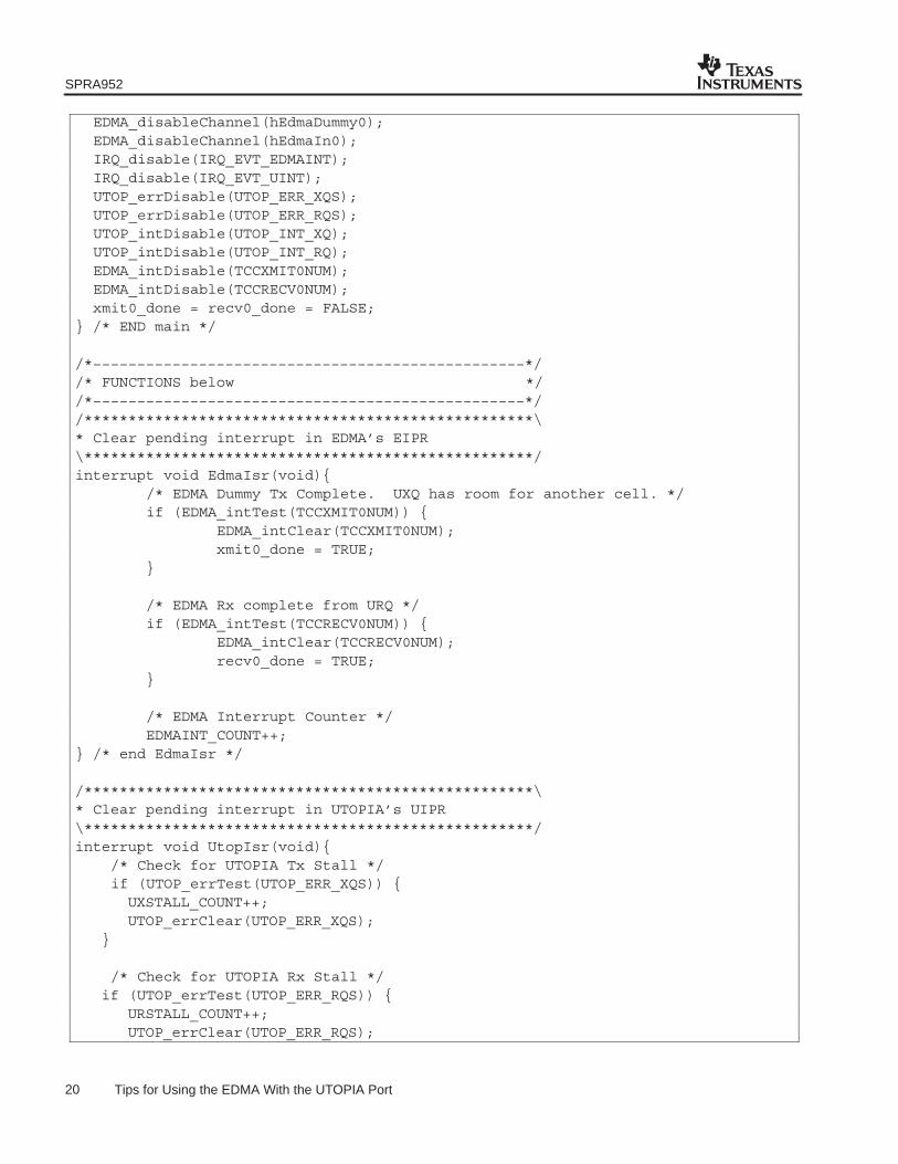
20 Tips for Using the EDMA With the UTOPIA Port
EDMA_disableChannel(hEdmaDummy0); EDMA_disableChannel(hEdmaIn0); IRQ_disable(IRQ_EVT_EDMAINT); IRQ_disable(IRQ_EVT_UINT); UTOP_errDisable(UTOP_ERR_XQS); UTOP_errDisable(UTOP_ERR_RQS); UTOP_intDisable(UTOP_INT_XQ); UTOP_intDisable(UTOP_INT_RQ); EDMA_intDisable(TCCXMIT0NUM); EDMA_intDisable(TCCRECV0NUM); xmit0_done = recv0_done = FALSE;} /* END main */
/*−−−−−−−−−−−−−−−−−−−−−−−−−−−−−−−−−−−−−−−−−−−−−−−−−*//* FUNCTIONS below *//*−−−−−−−−−−−−−−−−−−−−−−−−−−−−−−−−−−−−−−−−−−−−−−−−−*//***************************************************\* Clear pending interrupt in EDMA’s EIPR\***************************************************/interrupt void EdmaIsr(void){ /* EDMA Dummy Tx Complete. UXQ has room for another cell. */ if (EDMA_intTest(TCCXMIT0NUM)) { EDMA_intClear(TCCXMIT0NUM); xmit0_done = TRUE; } /* EDMA Rx complete from URQ */ if (EDMA_intTest(TCCRECV0NUM)) { EDMA_intClear(TCCRECV0NUM); recv0_done = TRUE; }
/* EDMA Interrupt Counter */ EDMAINT_COUNT++;} /* end EdmaIsr */
/***************************************************\* Clear pending interrupt in UTOPIA’s UIPR\***************************************************/interrupt void UtopIsr(void){ /* Check for UTOPIA Tx Stall */ if (UTOP_errTest(UTOP_ERR_XQS)) {
UXSTALL_COUNT++;UTOP_errClear(UTOP_ERR_XQS);
}
/* Check for UTOPIA Rx Stall */if (UTOP_errTest(UTOP_ERR_RQS)) {
URSTALL_COUNT++;UTOP_errClear(UTOP_ERR_RQS);
SPRA952
21 Tips for Using the EDMA With the UTOPIA Port
}
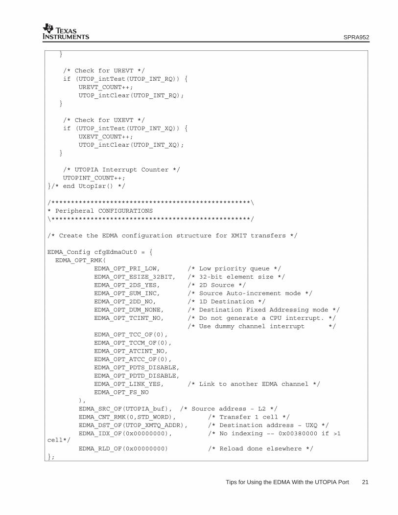
/* Check for UREVT */ if (UTOP_intTest(UTOP_INT_RQ)) { UREVT_COUNT++; UTOP_intClear(UTOP_INT_RQ);
}
/* Check for UXEVT */ if (UTOP_intTest(UTOP_INT_XQ)) { UXEVT_COUNT++; UTOP_intClear(UTOP_INT_XQ);
}
/* UTOPIA Interrupt Counter */ UTOPINT_COUNT++;}/* end UtopIsr() */
/***************************************************\* Peripheral CONFIGURATIONS\***************************************************/
/* Create the EDMA configuration structure for XMIT transfers */
EDMA_Config cfgEdmaOut0 = { EDMA_OPT_RMK(
EDMA_OPT_PRI_LOW, /* Low priority queue */EDMA_OPT_ESIZE_32BIT, /* 32-bit element size */EDMA_OPT_2DS_YES, /* 2D Source */EDMA_OPT_SUM_INC, /* Source Auto-increment mode */EDMA_OPT_2DD_NO, /* 1D Destination */EDMA_OPT_DUM_NONE, /* Destination Fixed Addressing mode */EDMA_OPT_TCINT_NO, /* Do not generate a CPU interrupt. */
/* Use dummy channel interrupt */EDMA_OPT_TCC_OF(0),EDMA_OPT_TCCM_OF(0),EDMA_OPT_ATCINT_NO,EDMA_OPT_ATCC_OF(0),EDMA_OPT_PDTS_DISABLE,EDMA_OPT_PDTD_DISABLE,EDMA_OPT_LINK_YES, /* Link to another EDMA channel */EDMA_OPT_FS_NO
), EDMA_SRC_OF(UTOPIA_buf), /* Source address − L2 */ EDMA_CNT_RMK(0,STD_WORD), /* Transfer 1 cell */ EDMA_DST_OF(UTOP_XMTQ_ADDR), /* Destination address − UXQ */ EDMA_IDX_OF(0x00000000), /* No indexing −− 0x00380000 if >1cell*/
EDMA_RLD_OF(0x00000000) /* Reload done elsewhere */};
SPRA952
22 Tips for Using the EDMA With the UTOPIA Port
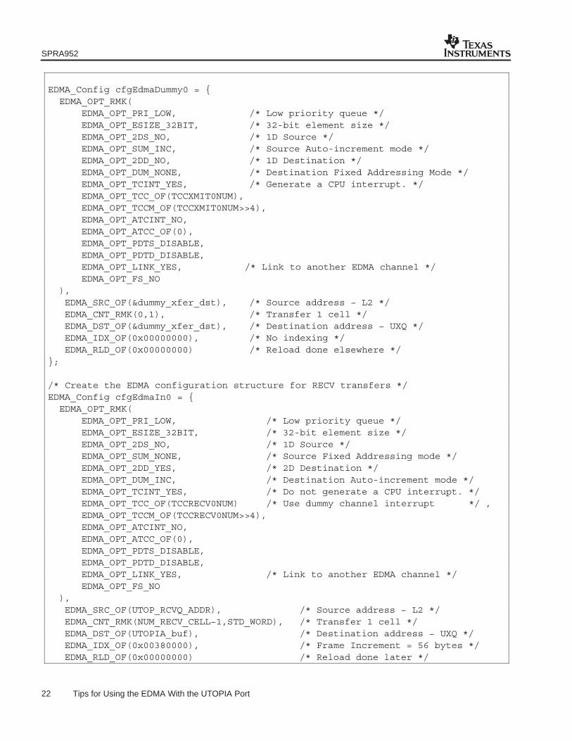
EDMA_Config cfgEdmaDummy0 = { EDMA_OPT_RMK(
EDMA_OPT_PRI_LOW, /* Low priority queue */EDMA_OPT_ESIZE_32BIT, /* 32-bit element size */EDMA_OPT_2DS_NO, /* 1D Source */EDMA_OPT_SUM_INC, /* Source Auto-increment mode */EDMA_OPT_2DD_NO, /* 1D Destination */EDMA_OPT_DUM_NONE, /* Destination Fixed Addressing Mode */EDMA_OPT_TCINT_YES, /* Generate a CPU interrupt. */EDMA_OPT_TCC_OF(TCCXMIT0NUM),EDMA_OPT_TCCM_OF(TCCXMIT0NUM>>4),EDMA_OPT_ATCINT_NO,EDMA_OPT_ATCC_OF(0),EDMA_OPT_PDTS_DISABLE,EDMA_OPT_PDTD_DISABLE,EDMA_OPT_LINK_YES, /* Link to another EDMA channel */EDMA_OPT_FS_NO
),EDMA_SRC_OF(&dummy_xfer_dst), /* Source address − L2 */EDMA_CNT_RMK(0,1), /* Transfer 1 cell */EDMA_DST_OF(&dummy_xfer_dst), /* Destination address − UXQ */EDMA_IDX_OF(0x00000000), /* No indexing */EDMA_RLD_OF(0x00000000) /* Reload done elsewhere */
};
/* Create the EDMA configuration structure for RECV transfers */EDMA_Config cfgEdmaIn0 = { EDMA_OPT_RMK(
EDMA_OPT_PRI_LOW, /* Low priority queue */EDMA_OPT_ESIZE_32BIT, /* 32-bit element size */EDMA_OPT_2DS_NO, /* 1D Source */EDMA_OPT_SUM_NONE, /* Source Fixed Addressing mode */EDMA_OPT_2DD_YES, /* 2D Destination */EDMA_OPT_DUM_INC, /* Destination Auto-increment mode */EDMA_OPT_TCINT_YES, /* Do not generate a CPU interrupt. */EDMA_OPT_TCC_OF(TCCRECV0NUM) /* Use dummy channel interrupt */ ,EDMA_OPT_TCCM_OF(TCCRECV0NUM>>4),EDMA_OPT_ATCINT_NO,EDMA_OPT_ATCC_OF(0),EDMA_OPT_PDTS_DISABLE,EDMA_OPT_PDTD_DISABLE,EDMA_OPT_LINK_YES, /* Link to another EDMA channel */EDMA_OPT_FS_NO
),EDMA_SRC_OF(UTOP_RCVQ_ADDR), /* Source address − L2 */EDMA_CNT_RMK(NUM_RECV_CELL−1,STD_WORD), /* Transfer 1 cell */EDMA_DST_OF(UTOPIA_buf), /* Destination address − UXQ */EDMA_IDX_OF(0x00380000), /* Frame Increment = 56 bytes */EDMA_RLD_OF(0x00000000) /* Reload done later */

SPRA952
23 Tips for Using the EDMA With the UTOPIA Port
};
/* Create the UTOPIA configuration structure */UTOP_Config cfgUtopia = {UTOP_UCR_RMK(
UTOP_ENDIAN, /* Little Endian */UTOP_UCR_SLID_OF(SLAVE_ID), /* SLID = 2 */UTOP_UCR_XUDC_DEFAULT, /* XUDC = 0 (Standard Cell) */UTOP_UCR_UXEN_DEFAULT, /* UXEN = 0 (Tx Disabled) */MPHY_MODE, /* MPHY = 1 (Multi−PHY Mode) */UTOP_UCR_RUDC_DEFAULT, /* RUDC = 0 (Standard Cell) */UTOP_UCR_UREN_DEFAULT /* UREN = 0 (Rx Disabled) */
), UTOP_CDR_RMK(
UTOP_CDR_XCCNT_DEFAULT, /* XCCNT = 255 */UTOP_CDR_RCCNT_DEFAULT /* RCCNT = 255 */
)};
/***************************************************\* Initialize data for recv src in testbench\***************************************************/voidinit_rsrc(void){
/* Fill buffer with incrementing numbers */ unsigned char *val; unsigned char j = 0; unsigned int i = 0;
val = (unsigned char *)UTOPIA_buf;
/* Set up transfer data */ for (i = 0; i < (STD_WORD*4*NUM_RECV_CELL); i++){ *val++ = j; j++; } /* end for */} /* end init_rsrc */
IMPORTANT NOTICE
Texas Instruments Incorporated and its subsidiaries (TI) reserve the right to make corrections, modifications,enhancements, improvements, and other changes to its products and services at any time and to discontinueany product or service without notice. Customers should obtain the latest relevant information before placingorders and should verify that such information is current and complete. All products are sold subject to TI’s termsand conditions of sale supplied at the time of order acknowledgment.
TI warrants performance of its hardware products to the specifications applicable at the time of sale inaccordance with TI’s standard warranty. Testing and other quality control techniques are used to the extent TIdeems necessary to support this warranty. Except where mandated by government requirements, testing of allparameters of each product is not necessarily performed.
TI assumes no liability for applications assistance or customer product design. Customers are responsible fortheir products and applications using TI components. To minimize the risks associated with customer productsand applications, customers should provide adequate design and operating safeguards.
TI does not warrant or represent that any license, either express or implied, is granted under any TI patent right,copyright, mask work right, or other TI intellectual property right relating to any combination, machine, or processin which TI products or services are used. Information published by TI regarding third-party products or servicesdoes not constitute a license from TI to use such products or services or a warranty or endorsement thereof.Use of such information may require a license from a third party under the patents or other intellectual propertyof the third party, or a license from TI under the patents or other intellectual property of TI.
Reproduction of information in TI data books or data sheets is permissible only if reproduction is withoutalteration and is accompanied by all associated warranties, conditions, limitations, and notices. Reproductionof this information with alteration is an unfair and deceptive business practice. TI is not responsible or liable forsuch altered documentation.
Resale of TI products or services with statements different from or beyond the parameters stated by TI for thatproduct or service voids all express and any implied warranties for the associated TI product or service andis an unfair and deceptive business practice. TI is not responsible or liable for any such statements.
Following are URLs where you can obtain information on other Texas Instruments products and applicationsolutions:
Products Applications
Amplifiers amplifier.ti.com Audio www.ti.com/audio
Data Converters dataconverter.ti.com Automotive www.ti.com/automotive
DSP dsp.ti.com Broadband www.ti.com/broadband
Interface interface.ti.com Digital Control www.ti.com/digitalcontrol
Logic logic.ti.com Military www.ti.com/military
Power Mgmt power.ti.com Optical Networking www.ti.com/opticalnetwork
Microcontrollers microcontroller.ti.com Security www.ti.com/security
Telephony www.ti.com/telephony
Video & Imaging www.ti.com/video
Wireless www.ti.com/wireless
Mailing Address: Texas Instruments
Post Office Box 655303 Dallas, Texas 75265
Copyright 2003, Texas Instruments Incorporated