Tipes Manual for Professional System
29
1
-
Upload
javier-bejar -
Category
Documents
-
view
43 -
download
3
Transcript of Tipes Manual for Professional System

1

2
Congratulations ! You now own one of the most sophisticated and experienced pigeon identification and racing real time systems on the market. TIPES is a simple-to-use system that allows precise and automatic measurement of pigeon racing performance. Naturally, you can’t wait to get this state of the art equipment running, but before you start, it’s worthwhile taking the time to read through this manual. Once you know about the features of TIPES, trouble-free operation is guaranteed. Please check if your TIPES is complete while you are unpacking the cardboard boxes. Make sure that no items are left inside the boxes. You should keep the TIPES cardboard boxes for future transportation or storage purposes. This manual is applicable to TIPES Professional and TIPES Junior as well, differences between Junior and Professional are indicated.
Contents 1 Introduction .............................................................................................................. 4
1.1 Safety instructions and precautions .................................................................. 4 1.2 The components of the TIPES system ........................................................... 5
1.2.1 The TIPES ring ......................................................................................... 5 1.2.2 The electronic trap...................................................................................... 5 1.2.3 The reading unit.......................................................................................... 5 1.2.4 The control unit........................................................................................... 7
2 Let’s get TIPES running ........................................................................................ 8 2.1 Installation of the electronic trap ....................................................................... 8 2.2 How to wire up TIPES ?................................................................................... 8
3 TIPES in action .................................................................................................... 10 3.1 Registration ..................................................................................................... 10 3.2 Allocation......................................................................................................... 12 3.3 Basketing ........................................................................................................ 13 3.4 Deletion ........................................................................................................... 16 3.5 Print................................................................................................................. 17
3.5.1 The race competition print out .................................................................. 19 3.6 Nomination ...................................................................................................... 20 3.7 PC-Communication ......................................................................................... 21
3.7.1 Transfer of breeders data ......................................................................... 21 3.7.2 Transfer of allocation table ....................................................................... 22 3.7.3 Transfer and deletion of liberation points ................................................. 22 3.7.4 Change of PIN-Code ................................................................................ 23 3.7.5 Programming of summer-/wintertime changing and time shift .................. 23
3.8 Selftest ............................................................................................................ 24 4 Ask Dr. TIPES before you call an engineer............................................................ 25
4.1 Checking and changing of fuses ..................................................................... 26 5 Technical data ....................................................................................................... 27

3
6 Guarantee Conditions............................................................................................ 28 7 Index ...................................................................................................................... 29
4
1 Introduction TIPES is based on modern radio and computer technology developments and offers a variety of advantages for you as well as for your club. TIPES offers: • automatic pigeon identification for up to 445 birds • automatic basketing and clocking capability for up to 350 birds • up to 30 liberation points programmable • print out of race entry form and clock roll on serial printer (TIPES Professional
users: printout at home possible) • automatic satellite based clock setting at the club and automatic time adjustment
for your local time • 12-volt-backup supply input with automatic switch-over in case of mains power
interruption (not TIPES Junior )
1.1 Safety instructions and precautions
The manufacturer cannot be held responsible for any damage which is incurred by not using TIPES in compliance with the following safety instructions. • First check if your supply voltage is the same as that written on the type plate on
the bottom of your TIPES reading unit. • TIPES does not contain any parts that can be repaired by the user. Any attempt
to open one of the TIPES units is made visible as the units are sealed. Please note that destroyed seals make all stored race data invalid. The units may only be opened by authorized TIPES service personnel.
• For system setup refer to this manual and to the mounting instructions for the electronic trap. For setup of the race office please refer to the master unit manual.
To switch off TIPES completely you must disconnect the reading unit from the mains.
• Ensure that air can circulate freely through the openings on top and bottom of the reading unit. Protect the reading unit and the control unit as well as all connectors from rain and moisture.
• Make sure that the electronic trap is not placed in a puddle during rain. The trap installation should provide proper draining of water.
• Do not place the reading unit or the control unit close to sources of heat such as radiators etc.
• The reading unit and the control unit should only be used inside a building. Do not use these units immediately after moving them from a cold to a warm location. Before powering, on allow at least 60 minutes to acclimatize.
• Any change or modification of the TIPES system or a component of this system requires explicit written approval of the manufacturer. Unauthorized modification does abolish the general operation agreement.

5
1.2 The components of the TIPES system
Let’s have a closer look at the TIPES components now. A short overview will give you information concerning the purpose of each individual unit so that you can easily understand the way the system works.
1.2.1 The TIPES ring In addition to the usual association ring each pigeon that shall be detected and identified by TIPES needs to wear a TIPES ring. This very light plastic ring carries an electronic identification circuit that transmits its electronic ring number to the electronic trap. This electronic ring number enables the TIPES system to identify each individual pigeon passing the trap. The manufacturer guarantees that each electronic ring has a unique number, worldwide. In addition the black TIPES ring (type 400 or 500) features a special anti-deception circuit. Before each race when the pigeons are basketed with the master unit (race office unit) the ring electronics will generate a random number which is rechecked when the arriving pigeon is detected by the electronic trap.
1.2.2 The electronic trap The electronic trap offers automatic detection capability for TIPES rings. The trap is powered from the reading unit automatically. Your pigeons will get used to the trap quickly. They will accept entering the loft through this entrance when they learn that they are no longer caught after racing. Please refer to the trap mounting instructions for proper setup and installation.
1.2.3 The reading unit The reading unit (Professional) contains a switch mode power supply and generates all supply voltages necessary to power the trap(s) as well as the control unit. The reading unit (Junior) has an external power supply that provides all supply voltages necessary to power the trap(s) as well as the control unit. The electronic ring numbers detected by the trap are transferred to the reading unit via the trap cable that is connected to the trap inputs on the rear of the reading unit. This data is immediately sent to the control unit which must be connected to the matching connector on the front of the reading unit. Note:
If you want to connect more than three traps to your reading unit, then you are in need of a TIPES-SUPRA that enables you to connect up to five traps to your reading unit. With additional TIPES-SUPRAs you can increase the number of traps up to 18 ! Please contact your distributor for more information.
The connector for the radio clock located on the rear of the reading unit is only used in Germany, Austria, Switzerland and Denmark. The internal clock of your TIPES control unit will be adjusted by the master unit whenever pigeons are basketed.

6
Front of reading unit
Note: The TIPES Junior reading unit only provides the connector to the control unit on it’s front.
T3.5AL250V T700mAL250V
Rear of reading unit
Note: The TIPES Junior reading unit does not provide a mains power input
connector on the rear. The external power supply has to be connected to the 12-volt connector.
Main power switch
connectors for up to 3
electronic traps
power indicators, red light indicates power from mains, yellow light indicates power from 12-volt-battery or accumulator
connector for 12-volt-battery or accumulator
connector to serial printer or personal computer (RS 232 interface)
fuse holder for 12-volt-supply from
battery or accumulator
connector to control unit
mains connector with integrated
fuse holder
connector for radio clock
- not used -

7
1.2.4 The control unit The control unit contains a special computer board designed to process and store pigeon data and arrival times, to generate ranking lists and to provide communication capability to a personal computer (via reading unit or master unit). Furthermore the control unit is the input terminal for pigeon nominations.
Front of control unit
It is possible to use the control unit without a reading unit. In this case you need a 12 volt power supply with standard circular connector.
Use only with a UL listed, Canadian certified class 2 power supply rated 12 volts dc, 500 mA.
display
connector for interconnection cable to
reading unit
numeric input keys
up and down keys for cursor
movement
display illumination on/off
ENTER key
ESCAPE key
SHIFT key
connector for 12 volt power supply
INFO key
NOMINATION key
TIME SETTING key

8
2 Let’s get TIPES running
This chapter will help you to install TIPES and to set up the system properly.
2.1 Installation of the electronic trap
Please refer to the mounting instructions when assembling the 4-field trap. Correct assembly of the pigeon stopper and the partitions is required for best detection performance.
Every metal material (not small items like screws or nails) within a range of 20 centimeters below the bottom of the trap will cause a negative impact on the detection quality.
TIPES traps are available with various cable lengths. Nevertheless, whenever you need an extension cable please contact your TIPES distributor. He can order any special model. Please notice that cable length to the traps, extensions included, is limited to 25 meters due to power loss on long cables. To comply with the FCC regulations the minimum distance between two installed traps has to be at least 3 meters.
2.2 How to wire up TIPES ?
It is necessary to plug in all cables before turning on the reading unit.
• Plug the trap cable(s) into the matching connector(s) (trap symbol) on the rear of the reading unit. You can connect up to three traps.
• If you want to use a 12-volt accumulator attach the matching black cable to the (square) 12-volt input connector on the rear of the reading unit. If you are going to use the 110 to 240-volt main supply, plug the black main power cable into the matching connector on the rear of the reading unit.
Note: The Junior system can only be powered by external 12-volt power supply or 12-volts accumulator.
If you use a 12-volt source as well as the 110 to 240-volt mains then TIPES will run on 110 to 240-volt unless it is forced to switch to the 12-volt supply in case of mains power interruption.
• Now it’s time to connect the control unit to the reading unit. Therefore plug the smaller connector of the gray interconnection cable into the right plug (control unit symbol) on the front of the reading unit. The plug on the other end fits into the control unit connector.
9
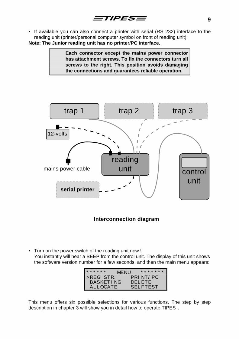
• If available you can also connect a printer with serial (RS 232) interface to the reading unit (printer/personal computer symbol on front of reading unit).
Note: The Junior reading unit has no printer/PC interface.
Each connector except the mains power connector has attachment screws. To fix the connectors turn all screws to the right. This position avoids damaging the connections and guarantees reliable operation.
Interconnection diagram
trap 1 trap 2 trap 3
readingunit control
unit
mains power cable
12-volts
serial printer
II
• Turn on the power switch of the reading unit now !
You instantly will hear a BEEP from the control unit. The display of this unit shows the software version number for a few seconds, and then the main menu appears:
This menu offers six possible selections for various functions. The step by step description in chapter 3 will show you in detail how to operate TIPES.
****** MENU ******* >REGISTR. PRINT/PC BASKETING DELETE ALLOCATE SELFTEST

10
3 TIPES in action
This chapter will show you how TIPES supports your activities before, during and after pigeon races. Whenever you don’t know how to leave a certain input position just switch off the reading unit. After power on you will automatically get to the main menu where all step by step descriptions start. Your stored data is saved even when you turn off the reading unit. Note: If you use the Junior system then disconnect the power supply from the
mains when the following description says „turn off the reading unit“.
3.1 Registration
Let’s start with the main menu:
1 ****** MENU ******* >REGISTR. PRINT/PC BASKETING DELETE ALLOCATE SELFTEST
• Move the arrow to REGISTR. with the ? ? (up/down) keys
• Press the (enter) key
2 *** REGISTRATING *** 08/22/1995 13:34:22 PRESS o FOR MANUAL TIME SETTING
The actual date and time is shown + Press the ¢ (cirle) key within 5
seconds if you want to adjust the internal clock.
3 *** REGISTRATING *** Date : __/__/__ Time : __:__ - Input date/time -
• Input date and time, use the ? ? (up/down) keys to move the cursor
• Press the (enter) key
This manual time adjustment is not selectable if basketed pigeons are in the memory so that this feature can only be used for training purposes. The internal clock of the control unit will be adjusted automatically during basketing for official races. 4 *** REGISTRATING ***
08/22/1995 13:34:22 READY!
TIPES is ready for registration now
- *** REGISTRATING *** !!! ERROR !!!
NO OR WRONG TRAP!
+ Make sure that at least one electronic trap is connected to the reading unit, or registration will not be possible.

11
After a pigeon has been detected the display will show the arrival time and date:
date ð
counter for ð timed in pigeons
*** REGISTRATING *** 08/22/1995 13:34:22 PL002 B95.1234567 Sidney 22/13:34:10
ñ liberation point ñarrival day/time
ï actual time ï pigeon association number
If a registered pigeon has not been previously allocated, then the control unit doesn’t know the proper association number and will just display the electronic number of the TIPES ring; for example: EL39A52C01. See chapter 3.2 for allocation.
During an ongoing race you can recall the number of pigeons that have yet been registered: perform steps 5 to 7 5 *** REGISTRATING ***
08/22/1995 13:34:22 PL 016 B95.1234567 Sidney
• Press the * (star) key
6 * INFO REGISTRATING ** Sidney 039/004 Paris 012/012 New York 055/000
Race from Sidney: 4 pigeons yet registered, 39 pigeons are basketed Race from Paris: All 12 pigeons are registered Race from New York: 55 basketed pigeons, 0 have arrived.
7 * INFO REGISTRATING ** New York 055/000 UNKNOWN 000/002
--- END ---
• Use the ? ? (up/down) keys to scroll this table
• Press # (escape) to leave this view or wait 15 seconds
The line UNKNOWN shows the number of registered pigeons that were not basketed. If you make a training flight during an ongoing race then these training pigeons will be registered as UNKNOWN.
You can leave the mode „registrating“ only by turning off the reading unit (for your safety).

12
3.2 Allocation
The control unit needs to know the electronic number of each TIPES ring that is attached to your pigeons. The control unit can store a cross reference table with all your pigeons association numbers and the matching electronic numbers of the TIPES rings. This table enables your TIPES to always display the association numbers you are familiar with. Now let’s see how your control unit „learns“ all those numbers:
Use the master unit for allocation !
• Make sure that the master unit is connected to the club personal computer via the PC interface. Refer to the master unit (race office unit) manual for detailed setup instructions.
• The administration software has to run and the allocation mode has to be selected. Please refer to the administration software manual.
• Connect your control unit to the master unit . 8 ****** MENU *******
REGISTR. PRINT/PC BASKETING DELETE >ALLOCATE SELFTEST
• Move the arrow to ALLOCATE with the ? ? (up/down) keys
• Press the (enter) key
9 ***** ALLOCATE ******
READY!
• The master unit is now active. The „READY“ message will disappear after a few seconds.
- ***** ALLOCATE ****** ERROR : USE MASTER UNIT FOR ALLOCATION!
+ Make sure that a master unit is connected to your control unit.
Every registered pigeon will now be displayed with the electronic number: 10 ***** ALLOCATE ******
EL 3904ABC9
+ This number instantly disappears from the display to the personal computer when the „Allocate“ command is entered. There it is matched in the cross reference table to the association (metal ring) number preselected by the PC operator.
• When all your pigeons have been allocated disconnect your control unit from the
master unit. The cross reference table now has to be copied into the control unit. • Reconnect your control unit and see chapter 3.7 for data transfer.

13
3.3 Basketing
This chapter describes how you get your pigeons registered with the master unit. During the basketing procedure the internal clock of your control unit is automatically adjusted by the master unit. The time signal is sent from the satellites of the global positioning system (GPS) which works in every area of the world.
Use the master unit for basketing !
• Make sure that the (GPS) time receiver is connected to the master unit. • Connect your control unit to the master unit. 11 ****** MENU *******
REGISTR. PRINT/PC >BASKETING DELETE ALLOCATE SELFTEST
• Move the arrow to BASKETING with the ? ? (up/down) keys
• Press the (enter) key
12 **** BASKETING ***** TIME SIGNAL
DETECTION QUALITY LEVEL (2)
Satellite search takes a few minutes. Best performance is guaranteed in open air. Concrete walls and buildings diminish the radio signal strength.
• TIPES is now searching for the satellite signals.
+ The GPS requires signals from 4 satellites. Move the time receiver antenna if the number of detected satellites does not reach this value.
This time adjustment will start automatically if the internal clock of the master unit has not been adjusted within the last 24 hours. Normally the first control unit connected to the master unit will start the GPS satellite search when the basketing mode is selected.
The internal clock of all following control units will then be adjusted from the master unit clock automatically. Satellite search may be skipped in case the GPS has been connected to the master unit several minutes before the first control unit is connected for basketing. Satellite search may have already completed.
- **** BASKETING *****
ERROR: NO ANSWER FROM
TIME RECEIVER
+ Make sure that a time receiver (radio clock or GPS) is connected to the master unit. Turn off master unit and start

14
with step 11 again.
15
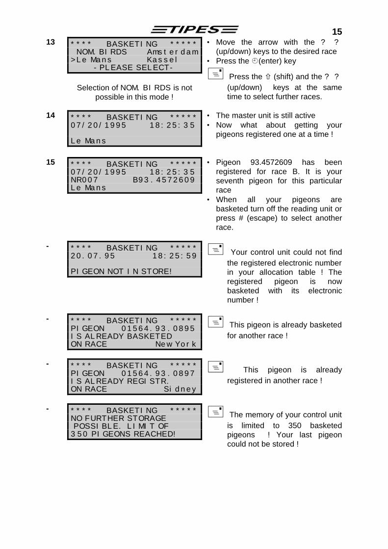
13 **** BASKETING ***** NOM.BIRDS Amsterdam >Le Mans Kassel
-PLEASE SELECT-
Selection of NOM.BIRDS is not
possible in this mode !
• Move the arrow with the ? ? (up/down) keys to the desired race
• Press the ¿(enter) key
+ Press the ñ (shift) and the ? ? (up/down) keys at the same time to select further races.
14 **** BASKETING *****
07/20/1995 18:25:35 Le Mans
• The master unit is still active • Now what about getting your
pigeons registered one at a time !
15 **** BASKETING ***** 07/20/1995 18:25:35 NR007 B93.4572609 Le Mans
• Pigeon 93.4572609 has been registered for race B. It is your seventh pigeon for this particular race
• When all your pigeons are basketed turn off the reading unit or press # (escape) to select another race.
- **** BASKETING *****
20.07.95 18:25:59 PIGEON NOT IN STORE!
+ Your control unit could not find the registered electronic number in your allocation table ! The registered pigeon is now basketed with its electronic number !
- **** BASKETING *****
PIGEON 01564.93.0895 IS ALREADY BASKETED ON RACE New York
+ This pigeon is already basketed for another race !
- **** BASKETING ***** PIGEON 01564.93.0897 IS ALREADY REGISTR. ON RACE Sidney
+ This pigeon is already registered in another race !
- **** BASKETING ***** NO FURTHER STORAGE POSSIBLE. LIMIT OF 350 PIGEONS REACHED!
+ The memory of your control unit is limited to 350 basketed pigeons ! Your last pigeon could not be stored !

16
Deletion
Every pigeon can only be registered one time. If you want this pigeon to participate in the next race you first have to delete the race data. Look how it works: 16 ****** MENU *******
REGISTR. PRINT/PC BASKETING >DELETE ALLOCATE SELFTEST
• Move the arrow to DELETE with the ? ? (up/down) keys
• Press the (enter) key
17 ***** DELETION ***** INPUT PIN-CODE:
_ _ _ _ _ _
• Enter your PIN-Code.
+ The PIN-Code preset from the manufacturer is: 123456 ! If you want to change your PIN-Code refer to step 43.
- ***** DELETION ***** INPUT PIN-CODE:
***_ _ _ WRONG NUMBER!
• Every correct number is indicated by a *.
+ If you enter a wrong number then you have to start again !
18 ***** DELETION ***** START OF DELETION IN 10 SECONDS
STOP WITH KEY!
• Press any key if you want to abort the deletion procedure !
19 ***** DELETION *****
ALL RACES ARE DELETED
• Race data is deleted.
The control unit is going to switch back to the main menu within a few seconds.
17
3.4 Print
TIPES can generate printouts of basketed pigeons after basketing or of registered pigeons after a training flight or a race.
Use the master unit for the printing of „official“ clockrolls! A printout can also be made via a usual reading unit (not TIPES Junior) but the starting and closing knockoffs will not be printed due to the lack of a valid time signal.
• Make sure that a time receiver is connected to the master unit . • Connect your control unit to the master unit. • A serial printer (RS 232 interface) has to be connected to the printer connector of
the master unit. The printer has to be on line; please refer to the printer manual. Presettings for the printer are:
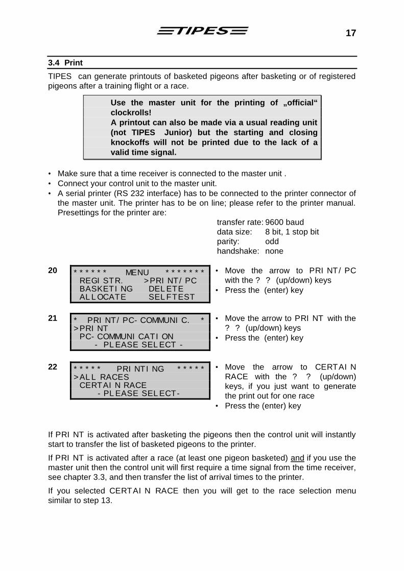
transfer rate: 9600 baud data size: 8 bit, 1 stop bit parity: odd handshake: none 20 ****** MENU *******
REGISTR. >PRINT/PC BASKETING DELETE ALLOCATE SELFTEST
• Move the arrow to PRINT/PC with the ? ? (up/down) keys
• Press the (enter) key
21 * PRINT/PC-COMMUNIC. * >PRINT PC-COMMUNICATION
- PLEASE SELECT -
• Move the arrow to PRINT with the ? ? (up/down) keys
• Press the (enter) key
22 ***** PRINTING ***** >ALL RACES CERTAIN RACE
-PLEASE SELECT-
• Move the arrow to CERTAIN RACE with the ? ? (up/down) keys, if you just want to generate the print out for one race
• Press the (enter) key
If PRINT is activated after basketing the pigeons then the control unit will instantly start to transfer the list of basketed pigeons to the printer.
If PRINT is activated after a race (at least one pigeon basketed) and if you use the master unit then the control unit will first require a time signal from the time receiver, see chapter 3.3, and then transfer the list of arrival times to the printer.
If you selected CERTAIN RACE then you will get to the race selection menu similar to step 13.

18
23 ***** PRINTING *****
PRINTING RACE Paris
The control unit now transfers data of race Paris to the printer.
- ***** PRINTING ***** NO PIGEONS BASKETED FOR THIS RACE!
There are no pigeons basketed for the selected race. This message will be printed.
You can leave the printing mode and return to the main menu with the # (escape) key.

19
3.4.1 The race competition print out The following print out example gives you information about the all details that you can find on the race entry form / race competition print out. TIPES Race Competition Overview Date: 06/27/1995 Time: 19:05:02 Race entry form/Timetape Address: Jones, Tommy Lee Personal ID: 01010202007 18, Valley drive Club : 05425 45621 Brunswick Serialnr. : 03018283 -------------------------- Race: Le Mans No. As.-ringno. d. Timein El. Ring. Nom. Birds S ------------------------------------------------------------ 001 B.93.1234567w 27 185001 3904AABB 00000000 0 0 * 002 B.91.4567892 27 185232 390C45E1 00000000 0 0 * 003 B.92.9874321 27 185500 391A6189 00000000 0 0 * Additional basketed pigeons: ------------------------------------------------------------ Number of entry pigeons: 003 Number of timed in pigeons: 000 ============================================================ Master unit-Protocol: 18:49:01 06/27/1995 Le Mans ------------- ------------- ------------ Fancier Race office Race office Race: Paris No. As.-Ringno. d. Timein El. Ring. Nom. Birds S ------------------------------------------------------------ 001 B.95.9892321 27 103620 39017418 00000000 0 0 ! 002 B.95.1874202 27 104205 391B62A0 00000000 0 0 ! B.95.1293567 26 185001 3904826B 00000000 0 0 * B.95.1567392 26 185232 390E62E1 00000000 0 0 * Additional basketed pigeons: ------------------------------------------------------------ Number of entry pigeons: 004 Number of timed in pigeons: 002 ============================================================ Master unit-protocol: 18:49:01 06/27/1995 Paris Time Synchronization -protocol: knockoff time: 06/26/1995 18:49:58 06/26/1995 18:50:00 G closing knockoff:06/27/1995 20:25:02 06/27/1995 20:25:00 G Time difference to UTC: 002 : 000 Wintertime/summertime : 09/23 02:00 Summertime/wintertime : 03/23 02:00
fancier address
Serial number of control unit
Race name
Date and Time of print out
Ranking No.
association ring number (w = female)
S = status: Q basketed ! timed in
arrival date
arrival time, i.e. 10:36:20 for No. 003
electronic number of TIPES ring
date and time of master unit connection, i.e. time of basketing
No. 001 and 002 timed in
internal clock time
corrected time based on time signal from time receiver

20
3.5 Nomination
Prior to the basketing of your pigeons you can store nominations for each pigeon into your TIPES control unit.
You can only nominate allocated pigeons.
24 ******* MENU ******** >REGISTR. PRINT/PC BASKETING DELETE ALLOCATE SELFTEST
• Press the ð (square) key for nomination
25 SELECT PIGEON: 678 B.93.00000001 1 2 3 4 5 6 7 8 A B
• Input up to 4 figures of the pigeon number and press the ↵ (enter) key or scroll through the allocation table using the ? ? (up/down) keys
• Press the ð (square) key again if the desired pigeon is selected
If there are already nominations stored for a certain pigeon then these will be displayed when this pigeon is selected. Nominations can be changed as long as the selected pigeon is not basketed.
+ Pigeons that are not allocated are marked with a „#“, pigeons that had been selected for nomination already are marked with a „$“.
26 NOMINATE PIGEON: B.93.12345678 1 2 3 4 5 6 7 8 A B 1 0 0 1 0 0 0 0 5 0
• Use the ? ? (up/down) keys to move the cursor to the desired nomination.
• Change the nomination value with numeric inputs: nominations 1 ... 8 with values 0 or 1, nominations A or B with values 0 ... 9
• Press the ↵ (enter) key for confirmation and storage or press the # key to abort and to return to the main menu.
+ If a selected pigeon has already been basketed (or registered) then a „*“ will be displayed in front of the pigeon number. In this case you can’t change the nominations!
Go to step 22 (chapter 3.5) and select CERTAIN RACE/NOM.BIRDS if you want to print out all nominated/not basketed birds. Note that nominated birds that are basketed will be printed under the corresponding race/liberation point.

21
3.6 PC-Communication
Your TIPES is able to exchange data with an IBM standard PC (at least 386). Data transfer is required to − store an allocation table into the control unit − store breeders identification data into the control unit − transfer and delete liberation points − change the PIN secret code (see chapter 3.4 Deletion) − read arrival data from the control unit. • Connect your control unit to the master unit. • The personal computer has to be connected to the PC connector on the rear of
the master unit. 27 ****** MENU *******
REGISTR. >PRINT/PC BASKETING DELETE ALLOCATE SELFTEST
• Move the arrow to PRINT/PC with the ? ? (up/down) keys
• Press the (enter) key
28 * PRINT/PC-COMMUNIC. * PRINT >PC-COMMUNICATION
- PLEASE SELECT -
• Move the arrow to PC-COMMUNICATION with the ? ? (up/down) keys
• Press the (enter) key
29 ** PC-COMMUNICATION **
READY!
• Make the administration software start the race data transfer, refer to the administration software manual.
You can leave the PC-communication mode by pressing the # (escape) key.
3.6.1 Transfer of breeders data Steps 14 to 19 are only required if fancier and club data are not yet stored in the control unit. Refer to administration software manual for further information. 30 ** PC-COMMUNICATION **
READY!
• Make the administration software transfer your breeder identification to your control unit.
31 PROGRAMMING NAME OF FANCIER!
The administration software will now transfer your identification data to the control unit.
32 PROGRAMMING ID-CODE OF FANCIER!
The data transfer is pretty fast so that you perhaps can’t read the messages on the display as fast as they appear.

22
33 PROGRAMMING ADDRESS
OF FANCIER!
34 PROGRAMMING CLUB NUMBER!
35 PROGRAMMING SERIAL NUMBER!
• Return to step 29
3.6.2 Transfer of allocation table
A new allocation table can only be stored into your control unit when all race data is deleted ! See chapter 3.4.
36 ** PC-COMMUNICATION **
READY!
• Make the administration software transfer the allocation table to your control unit.
- ** PC-COMMUNICATION ** TO RECEIVE ALLOCA- TION-TABLE RACE DATA HAS TO BE DELETED!
+ Race data has not been deleted
• Press # (escape) to return to the main menu and perform steps 16 to 19 before starting with step 36 again
37 ** PC-COMMUNICATION **
RECEIVING NEW ALLOCATION-TABLE!
• The new allocation table is stored into the control unit memory.
38 ** PC-COMMUNICATION **
READY!
• Now your control unit is „loaded“ with your pigeon numbers
• Press # (escape) to return to the main menu and go on with step 39.
3.6.3 Transfer and deletion of liberation points As your control unit is connected to the personal computer via the reading unit you can also take the opportunity to program new or additional liberation points into your control unit.

23
39 ** PC-COMMUNICATION **
READY!
• Make the administration software transfer the selected liberation points to your control unit
40 ** PC-COMMUNICATION **
PROGRAMMING LIBERATION POINTS!
• Return to step 29
You can store up to 30 liberation points in your control unit. Whenever you transfer liberation points to the control unit they will be added to the ones already stored in the control unit’s memory. If the sum of those already stored plus those transferred exceeds the number of 30 then the control unit will first require deletion of the ones already in memory. 41 ** PC-COMMUNICATION **
READY!
• Make the administration software delete the liberation points in your control unit
42 ** PC-COMMUNICATION ** DELETING LIBERATION POINTS!
• Return to step 29 or go on with step 43
3.6.4 Change of PIN-Code The PIN code may be changed any time. 43 ** PC-COMMUNICATION **
READY!
• Make the administration software transfer your new PIN-Code to your control unit.
44 ** PC-COMMUNICATION ** PROGRAMMING PIN-CODE OF FANCIER!
• Return to step 29 or go on with step 45
3.6.5 Programming of summer-/wintertime changing and time shift The internal clock of of your control unit will be adjusted by the master unit automatically during the basketing of pigeons. The master unit gets its time signal from the GPS time receiver. These satellite time signals represent UTC time which might be different from your local time. The time shift to UTC time can be programmed into your control unit so that the control unit automatically calculates the local time. Use the administration software to program the time shift and the summer-/wintertime changes: 45 ** PC-COMMUNICATION ** • Make the administration software

24
READY!
transfer the time shift information to your control unit.
+ Race data has not to be deleted before starting this step !
3.7 Selftest
TIPES offers selftest capability. You can start the selftest procedure whenever you suspect a problem. 46 ****** MENU *******
REGISTR. PRINT/PC BASKETING DELETE ALLOCATE >SELFTEST
• Move the arrow to SELFTEST with the ? ? (up/down) keys
• Press the (enter) key
47 ***** SELFTEST ***** RAM :OK RTC :OK EPROM:OK EEPR.:OK RU :OK .
It will take a few seconds until the selftest result is displayed. RU means reading unit; each dot after RU represents one connected trap.
48 ***** SELFTEST *****
--- OK --- SWITCH SYSTEM OFF!
• Turn off the reading unit when the selftest result is displayed.

25
4 Ask Dr. TIPES before you call for support
TIPES is a very reliable system but nevertheless it is possible that TIPES does not work the way it should. With Dr. TIPES you are able to solve most problems within a few minutes. If you are not successful then contact your distributor for support.
Problem Possible cause Several pigeons are not registered
• The pigeons were registered before and the control unit has not been deleted since then. Each pigeon can only be registered one time after deletion.
• Cable between Control and reading unit might be damaged. Check connector for proper pin positions.
• One or more entrances of the electronic trap(s) might have failed.
• If your TIPES runs on battery power the battery perhaps is weak. Never charge a connected battery while operating with TIPES !
• Check for metal construction under the antenna. Any metal material within 30 centimeters below the trap can cause detection problems (not nails or screws).
Time receiver does not receive time signal.
• The time receiver requires proper radio signals from at least four satellites. Signals may be disturbed by big buildings and concrete walls. Make sure that the time receiver antenna is placed in open air. If necessary use an extension cable.
Your print out shows gaps • Your printer is too slow so that the printer buffer can´t keep all data. Select „DRAFT“ mode on printer. This mode is much faster than „LETTER QUALITY“ (LQ) and „NEAR LETTER QUALITY“ (NLQ).
Your print out produces blank pages
• Turn „AUTO FORM FEED“ to the off position on the printer. The form feed command is generated by the control unit automatically.
• Check the printer preselections for the correct paper format.
No printout possible • Your printer cable might have wrong interconnections. The proper pin setting is: RxD-signal - pin 2, TxD-signal - pin 3, GND - pin 5 (reading unit connector).
• Contact your ditributor for further information.
Mains or accumulator are connected but the power indicator does not indicate power after turning the unit on.
• Check the fuses (chapter 4.1)

26
4.1 Checking and changing of fuses
If power, (mains or battery), is connected to the reading and the corresponding indicator on the front does not indicate such, then you should check the fuses. The mains fuse is located in the black connector housing on the rear of the reading unit.
Make sure that the mains power cable is disconnected from your mains plug and from the reading unit.
Note: The Junior reading unit has no indicator for the supply voltage.
Use a small screwdriver to tear the small fuse holder from the connector housing. You can remove the fuse. If the wire is visible in the glass tube then the fuse is OK. If there is no wire visible then you have to replace the fuse.
For continued protection against risk of fire, replace only with the same type and rating of the fuse. Correct type is: T700mAL250V.
Note: The Junior reading unit has no 110 - 240-volt input connector.
Place the working or new fuse into the fuse holder and push it back into the connector housing.
T3.5AL250V T700mAL250V
Fuse holder location
The fuse for the 12-volt DC input is located in the circular fuse holder under the 12 volt connector on the rear of the reading unit. Use a screwdriver to push the cap in and turn it left. Then the fuse is released. If the wire is visible in the glass tube then the fuse is OK. If there is no wire visible then you have to replace the fuse.
For continued protection against risk of fire, replace only with the same type and rating of the fuse . Correct type is: T3.5AL250V or T4AL250V.
Place the working or new fuse into the fuse cap and push it back into the fuse holder.
fuse holder for 12 volt input fuse
fuse holder for mains input fuse
27
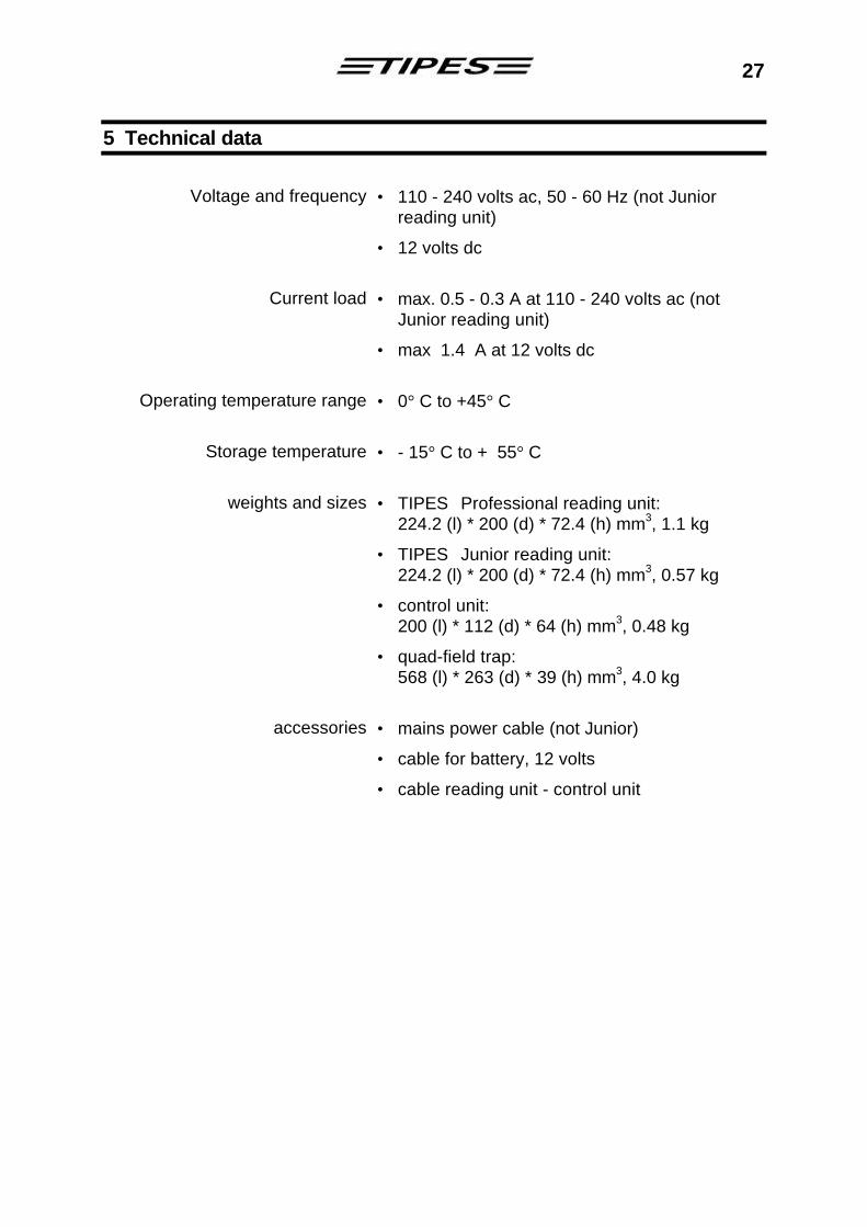
5 Technical data
Voltage and frequency • 110 - 240 volts ac, 50 - 60 Hz (not Junior
reading unit)
• 12 volts dc
Current load • max. 0.5 - 0.3 A at 110 - 240 volts ac (not Junior reading unit)
• max 1.4 A at 12 volts dc
Operating temperature range • 0° C to +45° C
Storage temperature • - 15° C to + 55° C
weights and sizes • TIPES Professional reading unit: 224.2 (l) * 200 (d) * 72.4 (h) mm3, 1.1 kg
• TIPES Junior reading unit: 224.2 (l) * 200 (d) * 72.4 (h) mm3, 0.57 kg
• control unit: 200 (l) * 112 (d) * 64 (h) mm3, 0.48 kg
• quad-field trap: 568 (l) * 263 (d) * 39 (h) mm3, 4.0 kg
accessories • mains power cable (not Junior)
• cable for battery, 12 volts
• cable reading unit - control unit

28
6 Guarantee Conditions
The manufacturer, DIEHL Ident Germany, offers the following guarantee to the first purchaser of TIPES components:
1. The guarantee is valid for 12 months commencing when the unit is handed over to the purchaser which must be verified by purchaser invoice or similar documentation.
2. The guarantee covers all parts or components which fail due to faulty workmanship or faulty material. The guarantee does not cover TIPES components where defects or poor performance are due to misuse, faults in the building wire, accidental damage, neglect, faulty installation, unauthorized modification or attempted repair or failure to use the unit in accordance with the operating instructions.
3. Should guarantee repairs be necessary the purchaser must inform the nearest customer service (distributor or authorized service partner).
4. The guarantee or free replacement includes both labor and materials.
5. Repairs carried out under guarantee do not extend the guarantee period. Parts removed during guarantee repairs become the property of DIEHL Ident.

29
7 Index
—1— 12-volt accumulator 8
—A— accessories 27 administration software 12 Allocation 12 allocation table 22 arrival times 7 association numbers 12 automatic detection 5 automatic pigeon identification 4
—B— Basketing 13 BEEP 9
—C— changing of fuses 26 club antenna 12, 13, 17 components of the TIPES system 5 control unit 7 Current load 27
—D— Deletion 16 detection quality 8
—E— electronic number 11 electronic number: 12 electronic ring 5 electronic trap 5
—F— fuse holder 26 fuses 25
—G— global positioning system 13 guarantee 28
—I— Installation of the electronic trap 8
—L— liberation point 11 liberation points 21, 23
—M— main menu 9, 10 manual time adjustment 10 metal material 8 moisture 4
—N— Nomination 20
—O— Operating temperatur 27
—P— PC-Communication 21 PIN-Code 16, 23 power interruption 8 power loss on long cables 8 power supply 5 Presettings for the printer 17 Print 17 print out 25 printer with serial (RS 232) interface 9
—R— race competition print out 19 reading unit 5, 9, 12 Registration 10
—S— safety 4 Safety 4 Selftest 24 summer-/wintertime 24
—T— time receiver 13 Time receiver 25 time shift 24 TIPES ring 5 TIPES-SUPRA 5
—U— UTC time 24
—W— weights and sizes 27