TIP LEAKAGE FLOWS IN TURBINES
38
TASK QUARTERLY 10 No 2, 139–175 TIP LEAKAGE FLOWS IN TURBINES PIOTR LAMPART Institute of Fluid-Flow Machinery, Polish Academy of Sciences, Fiszera 14, 80-952 Gdansk, Poland [email protected] (Received 7 February 2006; revised manuscript received 12 March 2006) Abstract: Mechanisms of formation of the tip leakage over shrouded and unshrouded rotor blades are described in the paper. The loss diagrams for these two types of leakage in a wide range of cascade inlet and outlet flow angles are also plotted. They are obtained in a theoretical way from a model of stream mixing with the help of simplifying assumptions concerning the load of the rotor profile. Results of numerical investigations based on a 3D RANS solver FlowER are also presented in the paper. They extend on the effects of geometrical and flow parameters of the cascade (stage or stage group) on the development of flow losses in the leakage-dominated region as well as on the interaction of tip leakage flow with secondary flows. The tip clearance size, the level of flow turning in the cascade, incidence angle and the effect of relative motion of the blades and endwall are considered here in the case of unshrouded free-tip blades. In the case of shrouded rotor blades the tip leakage mass flow rate and its direction on the re-entry to the blade-to-blade passage. Since the tip leakage non-uniformities are hardly dissipated within the blade row where they originate, the interaction of the tip leakage with the flow in the downstream stator is considered. Some investigations also take into account the effect of relative motion of the stator and rotor blades. Keywords: axial flow turbine, shrouded/unshrouded blades, tip leakage, CFD 1. Introduction Side flows are inherent to turbomachinery as they result from the presence of technological clearances between the fixed and rotating parts of machinery. Among different types of side flows are leakage flows over the rotor and stator blade tips of unshrouded blades, labyrinth flows over shrouded rotor blades and through stator root seals, windage flows at the rotor disc and discharge flows through the rotor disc discharge holes. A sample diagram of distribution of flow into the blade-to-blade passages and leakage flow clearances for a group of high-pressure (HP) stages of an impulse steam turbine with shrouded rotor blades is presented in Figure 1. Leakage streams bypass the blade-to-blade passage and do not yield work to the rotor. Therefore, they are sources of power loss in turbines. In this paper the attention is focused on the main form of leakage flow, that is the tip leakage over the rotating rotor blade. The tip leakage is characterised by parameters different than those of the main stream, which is documented by tq210r-e/139 11 I 2007 BOP s.c., http://www.bop.com.pl
Transcript of TIP LEAKAGE FLOWS IN TURBINES

TASK QUARTERLY 10 No 2, 139–175
TIP LEAKAGE FLOWS IN TURBINES
PIOTR LAMPART
Institute of Fluid-Flow Machinery,
Polish Academy of Sciences,
Fiszera 14, 80-952 Gdansk, Poland
(Received 7 February 2006; revised manuscript received 12 March 2006)
Abstract: Mechanisms of formation of the tip leakage over shrouded and unshrouded rotor bladesare described in the paper. The loss diagrams for these two types of leakage in a wide range ofcascade inlet and outlet flow angles are also plotted. They are obtained in a theoretical way froma model of stream mixing with the help of simplifying assumptions concerning the load of the rotorprofile. Results of numerical investigations based on a 3D RANS solver FlowER are also presentedin the paper. They extend on the effects of geometrical and flow parameters of the cascade (stageor stage group) on the development of flow losses in the leakage-dominated region as well as on theinteraction of tip leakage flow with secondary flows. The tip clearance size, the level of flow turning inthe cascade, incidence angle and the effect of relative motion of the blades and endwall are consideredhere in the case of unshrouded free-tip blades. In the case of shrouded rotor blades the tip leakagemass flow rate and its direction on the re-entry to the blade-to-blade passage. Since the tip leakagenon-uniformities are hardly dissipated within the blade row where they originate, the interaction ofthe tip leakage with the flow in the downstream stator is considered. Some investigations also takeinto account the effect of relative motion of the stator and rotor blades.
Keywords: axial flow turbine, shrouded/unshrouded blades, tip leakage, CFD
1. Introduction
Side flows are inherent to turbomachinery as they result from the presence oftechnological clearances between the fixed and rotating parts of machinery. Amongdifferent types of side flows are leakage flows over the rotor and stator blade tips ofunshrouded blades, labyrinth flows over shrouded rotor blades and through statorroot seals, windage flows at the rotor disc and discharge flows through the rotor discdischarge holes. A sample diagram of distribution of flow into the blade-to-bladepassages and leakage flow clearances for a group of high-pressure (HP) stages of animpulse steam turbine with shrouded rotor blades is presented in Figure 1. Leakagestreams bypass the blade-to-blade passage and do not yield work to the rotor.Therefore, they are sources of power loss in turbines.
In this paper the attention is focused on the main form of leakage flow, thatis the tip leakage over the rotating rotor blade. The tip leakage is characterisedby parameters different than those of the main stream, which is documented by
tq210r-e/139 11I2007 BOP s.c., http://www.bop.com.pl

140 P. Lampart
Figure 1. Impulse turbine geometry; G1, G2 – mass flow rates of the main flowin the blade-to-blade passage of the stator and rotor, GT , GR – flow rates of leakagesat the rotor blade tip and stator root, GW , GW ′ – windage flow rates at the rotor disc,
GH – flow rate at the rotor disc discharge holes
measurements on large-scale turbines, e.g. [1] or [2]. Particularly important is thedifference between the magnitudes and directions of the leakage flow and main streamvelocities, which gives rise to mixing losses on the re-entry of the leakage stream to theblade-to-blade passage. It is also important to note that the mechanism of formationof the tip leakage over unshrouded free-tip blades is different than that of leakageover shrouded blades, [3]. Therefore, these two types of leakage need to be consideredseparately.
2. Formation of tip leakage over unshrouded rotor blades
The mechanism of formation of the tip leakage in the gap over unshroudedrotor blades and its further development in the blade-to-blade passage is illustratedin Figure 2. The driving force for this type of leakage is the pressure difference that isformed over the blade tip between the pressure and suction surface of the blade. Due toa usually significant pressure gradient, the leakage stream is largely accelerated in thetip gap. In the transonic cascades, the tip leakage stream reaches supersonic velocitiesthat can be compared to those at the blade suction surface in the blade-to-bladepassage. At the entrance to the tip gap, the tip leakage typically separates from thesharp edge of the blade tip. The tip leakage is contracted into a narrow stream betweenthe separation region and endwall. Here, the leakage stream becomes turbulent andmixes with the shear layer separating it from the stagnation area. Downstream, theleakage jet fills the entire tip gap and further mixing takes place to equalise flownon-uniformities in the leakage stream. Downstream of the gap the tip leakage facesthe adverse pressure gradient in the channel and separates from the endwall forminga vortex structure that is convected downstream, [4–6]. A detailed investigation of
tq210r-e/140 11I2007 BOP s.c., http://www.bop.com.pl

Tip Leakage Flows in Turbines 141
the leakage stream in the tip gap is the subject of the paper [7]. The tip leakageflow is not turned in the blade-to-blade passage in a way the main stream is. Thetip leakage follows the pressure gradient across the tip gap, so its direction on there-entry to the blade-to-blade passage usually forms an oblique angle with the mainstream direction.
In [8], some effects are identified of the tip gap flow on the distribution ofstatic pressure at the endwall, which largely remains similar to that formed in theblade-to-blade passage, except for the gap region over the blade tip. This refers bothto the situation of fixed (non-rotating) blades and endwall as well as to the case ofrelative motion between the blade tip and endwall1. The main difference is a region ofdecreased pressure over the blade tip edge. This is a relatively small pressure decreaseabove the pressure surface and a more considerable pressure decrease above the suctionsurface, that is at the entry from the tip gap. This redistribution of pressure aroundthe blade tip results in a change of load of the blade tip. Typically, there is a minorchange in circumferential force that gives the rotational moment. More significant arechanges in axial force, where typically an increase of about 5–10% depending on thecascade geometry and tip gap size is observed, as compared to the cascade withouta tip clearance. These effects were documented by [6, 9–11].
Figure 2. Scheme of the tip leakage over unshrouded rotor blades
The presence of the tip gap over the blade usually eliminates the stagnation atthe endwall, which typically occurs in the corner between the endwall and bladeleading edge in the no tip gap configuration. Therefore, a horseshoe vortex doesnot feature at the tip endwall unless the tip gap is very small. The flow at the tipendwall approaching the tip region above the leading edge of the blade is dividedinto two streams aiming towards low pressure regions above the suction surfaces ofthe neighbouring blades – a main stream of the tip leakage flow going through thetip gap over the blade and a stream of cross-flow going across the blade-to-bladepassage [12]. The tip leakage flow leaving the tip gap separates from the endwall
1. Over the years, knowledge of the physics of tip leakage flow has mainly been acquiredfrom results of experimental investigations of model cascades with a tip clearance. Most of theseinvestigations were made on stationary cascades, only some investigations taking into account therelative motion of blade tips and endwalls. Investigations in a fully stationary environment enableddetailed measurements and thorough tracing of flow patterns, wheras taking into account the relativemotion assures the relevance of the experiment to real turbomachinery situations.
tq210r-e/141 11I2007 BOP s.c., http://www.bop.com.pl

142 P. Lampart
Figure 3. Tip leakage vortex and passage vortex at the tip endwall
under conditions of adverse pressure gradient and forms the tip leakage vortex. Thecross-flow blocked by the development of the tip leakage vortex also separates fromthe endwall and rolls up into a passage vortex. The stream dividing line betweenthe tip leakage and cross-passage flow lies at the pressure side of the blade tip, [13].The described situation is illustrated in Figure 3. The tip leakage vortex and passagevortex are characterised by the opposite sense of rotation. It follows from [14–16] thata dominant structure is the tip leakage vortex. The relations between the circulationand size of the two structures depend on many factors including the tip gap size, flowturning angle, blade load and incidence angle. For a typical low-load rotor cascadesfor the nominal inflow and typical tip gap size ranging between 1–3%, the circulationof the tip leakage vortex is several times larger than that of the passage vortex.
Interaction of the tip leakage vortex and passage vortex is a complex process. Inhigh-turning turbine cascades investigated in [17–19], as a result of shear interactionwith the larger tip leakage vortex, the passage vortex is moved towards mid-spansections, its structure elongated and circulation reduced. The circulation of thepassage vortex changes with the incidence at the blade and is largely decreasedwhen the incidence is moved towards the suction side, that is when the flow turningin the cascade is reduced. At the same time the circulation of the tip leakagevortex practically remains unchanged with the changing incidence angle, however,exhibits significant changes with the increasing tip gap width. The investigations ofa low-turning cascade presented in [20] show that the weaker passage vortex is quicklydissipated. The remains of vorticity of the sense of rotation the same as that of thepassage vortex are observed at the endwall/pressure surface corner near the separationof cross-flow from the endwall.
The tip leakage region is characterised by a high level of flow turbulence.Production of turbulent kinetic energy and its dissipation is a significant source of flowlosses. The results of detailed measurements presented in [21] indicate the turbulenceintensity of 30% (with respect to the inlet velocity) in the region of separation of thetip leakage flow from the endwall, in the tip leakage vortex and passage vortex as wellas in the region of high stress resulting from interaction of the two vortex structures.The turbulence intensity of the leakage stream in the tip gap exceeds locally 26%(with respect to the outlet velocity), [22].
tq210r-e/142 11I2007 BOP s.c., http://www.bop.com.pl
Tip Leakage Flows in Turbines 143
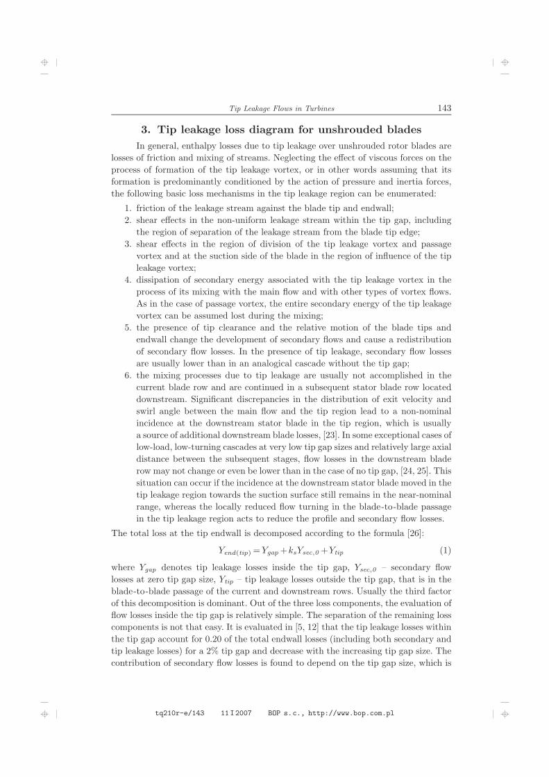
3. Tip leakage loss diagram for unshrouded blades
In general, enthalpy losses due to tip leakage over unshrouded rotor blades arelosses of friction and mixing of streams. Neglecting the effect of viscous forces on theprocess of formation of the tip leakage vortex, or in other words assuming that itsformation is predominantly conditioned by the action of pressure and inertia forces,the following basic loss mechanisms in the tip leakage region can be enumerated:
1. friction of the leakage stream against the blade tip and endwall;2. shear effects in the non-uniform leakage stream within the tip gap, includingthe region of separation of the leakage stream from the blade tip edge;
3. shear effects in the region of division of the tip leakage vortex and passagevortex and at the suction side of the blade in the region of influence of the tipleakage vortex;
4. dissipation of secondary energy associated with the tip leakage vortex in theprocess of its mixing with the main flow and with other types of vortex flows.As in the case of passage vortex, the entire secondary energy of the tip leakagevortex can be assumed lost during the mixing;
5. the presence of tip clearance and the relative motion of the blade tips andendwall change the development of secondary flows and cause a redistributionof secondary flow losses. In the presence of tip leakage, secondary flow lossesare usually lower than in an analogical cascade without the tip gap;
6. the mixing processes due to tip leakage are usually not accomplished in thecurrent blade row and are continued in a subsequent stator blade row locateddownstream. Significant discrepancies in the distribution of exit velocity andswirl angle between the main flow and the tip region lead to a non-nominalincidence at the downstream stator blade in the tip region, which is usuallya source of additional downstream blade losses, [23]. In some exceptional cases oflow-load, low-turning cascades at very low tip gap sizes and relatively large axialdistance between the subsequent stages, flow losses in the downstream bladerow may not change or even be lower than in the case of no tip gap, [24, 25]. Thissituation can occur if the incidence at the downstream stator blade moved in thetip leakage region towards the suction surface still remains in the near-nominalrange, whereas the locally reduced flow turning in the blade-to-blade passagein the tip leakage region acts to reduce the profile and secondary flow losses.
The total loss at the tip endwall is decomposed according to the formula [26]:
Yend(tip)=Ygap+ksYsec,0 +Ytip (1)
where Ygap denotes tip leakage losses inside the tip gap, Ysec,0 – secondary flowlosses at zero tip gap size, Ytip – tip leakage losses outside the tip gap, that is in theblade-to-blade passage of the current and downstream rows. Usually the third factorof this decomposition is dominant. Out of the three loss components, the evaluation offlow losses inside the tip gap is relatively simple. The separation of the remaining losscomponents is not that easy. It is evaluated in [5, 12] that the tip leakage losses withinthe tip gap account for 0.20 of the total endwall losses (including both secondary andtip leakage losses) for a 2% tip gap and decrease with the increasing tip gap size. Thecontribution of secondary flow losses is found to depend on the tip gap size, which is
tq210r-e/143 11I2007 BOP s.c., http://www.bop.com.pl

144 P. Lampart
accounted for in the form of the coefficient ks in Equation (1), ranging between zeroand unity and decreasing with the increasing tip gap size. The decomposition of thetotal endwall loss is tentatively illustrated in Figure 4 borrowed from experimentalinvestigations presented in [26]. The diagram was made for the case of a cascade withthe tip clearance but without taking into account the effect of relative motion of theblade tips and endwall. With the relative motion, one can expect a certain increase ofthe loss component within the tip gap due to increased stresses between the leakagestream and endwall in the relative motion.
Figure 4. Tentative diagram of contribution of loss components in the total endwall loss [26]
The size of the tip gap (relative to the channel height) is of primary importancefor the level of tip leakage losses, which is accounted for in all experimental andtheoretical tip leakage loss correlations, e.g. [26–29]. A linear relationship is usuallyassumed, which is supported by the results of experimental investigations presentedin [5, 26]. The correlations also take into account the effects of flow turning in thecascade and its density (pitch-to-chord ratio).
Enthalpy losses due to the tip leakage over unshrouded rotor blades can beestimated following the procedure described in [3] based on a model of mixing ofnon-parallel streams or a model of lost kinetic energy of the tip leakage flow relativeto the main flow, and making use of some simplified assumptions concerning the bladeload. The obtained final results may vary depending on the assumed model of mixingand blade load simplifications. Denton neglects the mixing within the tip gap andassumes that the mixing takes places at the suction surface of the blade, at a constantvolume and pressure. The main stream is the flow at the suction surface of velocityV1=Vs, Figure 5. Assuming that the static pressure of the tip leakage is the same asthat of the main stream at the suction surface, that is pj = p1 = ps, and neglectingany total pressure losses of the tip leakage and main stream until the area of mixing,one can obtain that the leakage stream velocity is equal to that of the main stream,Vj =V1=Vs. Denton also assumes that the streamwise velocity component of the tipleakage is equal to the main flow velocity at the pressure surface Vp, from where thetip leakage flow originates, and that further acceleration of the tip leakage in the tipgap takes place in the direction normal to the flow. This enables the determination ofvelocity components of the main flow and tip leakage as the entry conditions for the
tq210r-e/144 11I2007 BOP s.c., http://www.bop.com.pl

Tip Leakage Flows in Turbines 145
mixing process in the coordinate system along the streamwise, cross-flow and radialdirection, respectively:
V1= [Vs,0,0], Vj =[
Vp,√
V 2s −V 2p ,0]
. (2)
Figure 5. Model of mixing in the region of tip leakage over an unshrouded rotor blade [3]
The loss coefficient due to mixing of the tip leakage with the main stream,found from the condition of lost kinetic energy of the relative flow of the tip leakagecan be evaluated as follows:
ξ=∫
C
dmjm2
erele2=∫
C
dmjm2
V 2relV 22≈∫
C
dmjm1
V 2relV 21
=∫
C
dmjm1
(Vs−Vp)2+(
V 2s −V 2p)
V 2s=∫
C
dmjm12(
1−VpVs
)
,
(3)
with the integral along the profile chord C. The symbol m denotes the mass flow rate,e is the kinetic energy. Subscripts 1, j, 2 stand for the main stream, leakage streamand mixed-out stream, respectively. Subscripts s, p denote the suction and pressureside. It is assumed that the mass flow rate of the leakage stream is small with respectto that of the main or mixed-out stream (mj <<m1).
The mass flow rate of the main stream in Equation (3) can be found from theformula:
m1= ρhpVx, (4)
whereas the elementary mass flow rate of the leakage stream can be described as:
dmj = ρVjnCδδdC = ρ√
V 2s −V 2p CδδdC, (5)
where h is the blade height, p – cascade pitch, dC – the profile chord element, δ –tip gap size, Cδ – contraction coefficient for the tip leakage stream that expresses theeffect of partial blockage of the tip gap by the separation from the blade tip edgeand by the endwall boundary layer. Vx denotes the axial component of the main flowvelocity, Vjn is the velocity component of the leakage flow normal to the main flow.Thus, the loss coefficient takes the form:
ξ=Y =2Cδδh
C
p
1∫
0
Vs−VpVx
√
1−V 2pV 2sdx, (6)
which can further be transformed with the help of simplifying assumptions about thechordwise distribution of the profile load. Let us assume the model of a thin profilewith a constant load (constant suction and pressure surface velocity difference) alongthe chord, Vs−Vp = 2∆V = const, with the mean surface velocity V = (Vs+Vp)/2
tq210r-e/145 11I2007 BOP s.c., http://www.bop.com.pl

146 P. Lampart
linked to the axial velocity by the formula V cosα= Vx, where α is the current flowangle changing between the inlet and exit angle α0, α12, respectively. The surfacevelocity difference can be linked to the pitch-to-chord ratio p/C, whose reverse appearsin Equation (6), using the conservation equation for the circumferential componentof the momentum in blade-to-blade passage (neglecting the boundary layer losses):
1∫
0
ρC
(
V 2s2−V 2p2
)
cosαdx= ρpV 2x (tgα1−tgα0), ⇒ p/C =2∆V
Vx(tgα1−tgα0), (7)
which turns Equation (6) into
ξ=Y =2Cδδh(tgα1−tgα0)
1∫
0
√
1−V 2pV 2sdx
=2Cδδh(tgα1−tgα0)
1∫
0
√
1−(−∆V/Vx+1/cosα)
2
(∆V/Vx+1/cosα)2 dx.
(8)
A further assumption can be made that tgα changes linearly with x. An expressionfor the optimum value of the pitch-to-chord ratio or ∆V/Vx corresponding to thecase of minimum loss coefficient for the blade boundary layer can also be utilised. Asshown in [27], the minimum profile boundary layer loss for the assumed blade loaddistribution occurs at ∆V/Vx =
√
c1/3c2, yielding the following formula for the tipleakage loss coefficient:
ξ=2Cδδh
tgα1∫
tgα0
√
√
√
√
√
√
1−
(
−√
c1/3c2+√1+x2
)2
(
√
c1/3c2+√1+x2
)2 dx, (9)
where
c1=14
(
tgα1cos3α1
−tgα0cos3α0
+3c2
)
,
c2=12
(
tgα1cosα1
−tgα0cosα0
+lntgα1+ 1
cosα1
tgα0+ 1cosα0
)
.
(10)
Equation (9) can be integrated numerically for given pairs of cascade inlet and exitangles.
The contraction coefficient Cδ varies typically between 0.6 and 0.8 in the caseof no relative motion of the blade tips and endwall, [3, 30, 31]. For the case of relativemotion corresponding to the nominal rotational speed of the rotor blade, the value ofthe contraction coefficient obtained in [32] is decreased to 0.45. In [3], it is suggestedthat the contraction coefficient for the case of relative motion the blade tips andendwall should be reduced twice as compared to that of no relative motion. In [33],the basic value of the contraction coefficient for the case of relative motion is assumedas 0.3, however this value is corrected on non-nominal operating conditions accordingto the method presented in [34].
2. The circumferential (swirl) angle is measured here from the projection of the turbine axis inthe blade-to-blade plane.
tq210r-e/146 11I2007 BOP s.c., http://www.bop.com.pl

Tip Leakage Flows in Turbines 147
The diagram of the tip leakage loss coefficient for unshrouded blades asa function of cascade inlet and exit angles α0, α1 is presented in Figure 6. The diagramwas plotted based on Equation (9) for the 1% tip gap size, assuming the contractioncoefficient as Cδ =0.4. The tip leakage losses can change in a wide range depending onthe cascade inlet and exit angles. For a combination of inlet and exit angles typical forthe rotor cascade of the reaction stage α0=(−20̊ , 20̊ ), α1=(70̊ , 75̊ ), the calculatedloss coefficient ranges between 1.9–3.3%. In the case of a typical impulse stage, thatis α0 = (−65̊ , −60̊ ), α1 = (65̊ , 75̊ ), the calculated loss coefficient changes within2.9–4.9% for every 1% tip gap size relative to the channel height.
Figure 6. Tip leakage loss coefficient for unshrouded blades calculated from Equation (9)as a function of cascade inlet and exit angles α0, α1; δ=0.01h, Cδ =0.4
The presented results can be considered a first approximation of the phenomenathat accompany the tip leakage flow. This approximation does not take into accountthe effects of compressibility, usually very important in the case of LP turbine stageswith long unshrouded blades. Validation of the presented results on experimentaldata is not that easy since it is not easy to separate the tip leakage loss from othercomponents of endwall loss. Also most of detailed experimental investigations donot take into account the effect of relative motion of the blade tips and endwalls.Anyway it can be shown that the presented theoretical results are in agreement withthe experimental data. For example, in the case of a cascade investigated in [31]with the inlet angle −45̊ , exit angle 64̊ , without a relative motion, the measuredloss coefficient is equal to 8.7% for the tip gap size of 2.1% (this coefficient wasmeasured as a difference in the total loss for the tip gap cascade of that gap size andthe cascade with no tip gap). For the given combination of cascade angles, the losscoefficient predicted from the diagram 6 is equal to 2.3% (for the 1% tip gap size).Multiplying this value by the tip gap size and changing the contraction coefficientfrom 0.4 to 0.7 (corresponding to the case of no relative motion of blade tips andendwall) one can obtain the value of 8.5% (2.3%×2.1×0.7/0.4 = 8.5%), which fallsvery close to the measured value. For another cascade presented in [34] (inlet angle
tq210r-e/147 11I2007 BOP s.c., http://www.bop.com.pl

148 P. Lampart
32̊ , exit angle 76̊ ), also without a relative motion, the difference in measured valuesof total loss coefficient (related to the inlet velocity) for two tip gap sizes of 2.8% and1.7% (related this time to the profile chord) amounts to 7.5%. After recalculation ofthe loss coefficient into a value related to the exit velocity (U1 =1.7U0) and makingthe tip gap size non-dimensional with respect to the channel height (for this cascadethe blade height-to-chord ratio h/C = 2.11), it can be found that the measured tipleakage losses are equal to 4.9% for every 1% tip gap size (referred to the channelheight). For the given combination of cascade angles, the diagram 6 gives a value ofloss coefficient 2.7%. Changing the contraction coefficient from 0.4 to 0.7 yields finally4.7%, which again is very close to the measured value. A similar comparison can bemade for the cascade investigated in [18] (though the loss values are measured therein the section located a short distance downstream of the cascade trailing edge andrequire further recalculation to obtain mixed out values of the loss coefficient) as wellas for the cascade presented in [26]. However, this comparison will not be documentedhere for the sake of brevity.
Increased possibilities of investigating turbine flow phenomena, including tipleakage flow can be attributed to numerical modelling and development of flowsolvers based on the RANS approach. Using numerical methods enables e.g. tracingthe formation of the tip leakage vortex, its interaction with the main flow, passagevortex and other vortical flows. For this paper, a series of computations were madewith the help of a flow solver FlowER (3D RANS, perfect gas equation, k-ω SSTturbulence model, finite volume method, upwind differencing, ENO scheme), [35–37].The calculations converging to a steady-state were made in a one blade-to-bladepassage of the stator and rotor cascades on an H-type grid refined near the bladewalls and endwalls (y+ = 1−2), leading and trailing edges of the blades. Typically,there are 12–16 grid cells in each boundary layer. The number of cells in one blade rowreaches 500000 (92 axially, 76 radially, 72 pitchwise). The calculation region extendsalso on the clearance over the rotor blades.
Numerical investigations were carried out on an impulse stage of an intermedi-ate pressure (IP) turbine and a single rotor cascade of a high pressure (HP) turbine.The investigated IP stage has straight stator blades of height 100mm with the stan-dard profile N3 and straight unshrouded rotor blades with the profile R2. The charac-teristic dimensions of the stage cascades are: blade height-to-chord ratio h/C =0.97(stator) and 2.88 (rotor), pitch-to-chord ratio p/C = 0.68 (stator) and 0.79 (rotor).The exit-to-inlet pressure ratio is 0.70 (pressure drop from 4.3 to 3.0bar), inlet tem-perature 152̊ C. The Mach number downstream of the stator is then 0.7, downstreamof the rotor – 0.5. The investigations were made for a range of tip gap size from 1% to3% of the channel height taking into account the relative motion between the bladetips and endwall. The investigated single HP rotor cascade has straight unshroudedblades of height 60mm and profile R2. The basic geometric dimensions of the cascadeare: blade height-to-chord ratio – 2.00, pitch-to-chord ratio – 0.75. The calculationsof this cascade were made in a wide range of stagger angle, inlet angle and operatingconditions typical for HP turbine stages changed by varying the exit pressure. TheMach number ranged between 0.2–0.6. These investigations were also made for dif-ferent values of tip gap size, both with and without the effect of relative motion ofthe blade tips and endwall.
tq210r-e/148 11I2007 BOP s.c., http://www.bop.com.pl

Tip Leakage Flows in Turbines 149
Figure 7. Spanwise distribution of enthalpy losses in the rotor and stage of an IP turbinecalculated 40% axial chord downstream of the rotor trailing edge for three values of tip gap size
Figure 8. Spanwise distribution of exit velocity (top) and exit swirl angle (bottom) in the IPturbine stage in the rotating (left) and absolute (right) reference frame calculated 40% axial chord
downstream of the rotor trailing edge for three values of tip gap size
Figure 7 illustrates spanwise distributions of enthalpy losses in the rotor andstage of the IP turbine calculated using the flow solver FlowER for three values oftip gap size at a section located 40% of the axial chord downstream of the rotortrailing edge. Expressions used to calculate stator, rotor and stage losses are enclosedin Appendix. The region of accumulation of the tip leakage loss is located near thetip endwall. The maximum value of the area distribution of loss falls within the tipleakage vortex and coincides with the place where the highest stresses occur. A typicalspanwise distribution of loss contains a high peak near the tip endwall. Dissipation ofthis peak is usually not possible before the entry to the subsequent downstream stage.The tip leakage leads to non-uniformities in the spanwise distributions of the exitvelocity and exit angle presented in Figure 8. These distributions were calculated in
tq210r-e/149 11I2007 BOP s.c., http://www.bop.com.pl

150 P. Lampart
the rotating and absolute reference frames also 40% of the axial chord downstream ofthe rotor trailing edge. In the rotating frame of reference, the velocity in the region ofinfluence of the tip leakage vortex is typically lower than the velocity of the expandingmain stream. In the absolute reference frame, the velocity in the tip leakage region istypically much larger than that of the main stream, exceeding it by over 100m/s in theillustrated section. Since the leakage flow is deflected in another direction comparedto the main flow, there is a large discrepancy between the exit swirl angle in theregion of leakage and in the main stream. In the illustrated section, this discrepancyreaches 60̊ .
The form of the presented spanwise distributions depends on the location ofthe control section and evolves downstream as a result of dissipative processes takingplace in the flow. The effect of tip leakage non-uniformities on the subsequent bladelosses will be discussed later in this paper – in connection with leakage over shroudedblades in Section 7, over unshrouded blades in Section 8.
4. Effects of geometric and flow parameters
on the tip leakage over unshrouded blades
4.1. Tip gap size
Figure 9 illustrates secondary flow vectors in a section located 25% of the axialchord downstream of the IP rotor trailing edge, which clearly exhibit the presence oftwo vortex structures – tip leakage vortex and passage vortex. The relation betweenthe size of the tip leakage vortex and passage vortex depends on the tip gap size. In theinvestigated range of tip gap size the passage vortex remains closer to the tip endwall,whereas the centre of the tip leakage vortex is moved towards mid-span sections, itssize considerably larger than that of the passage vortex. The total pressure contoursat the trailing edge and downstream presented in Figure 10 also exhibit an increase insize of the tip leakage vortex and reduction in size of the tip passage vortex with theincreasing tip gap size. The smaller intensity of the tip passage vortex as comparedto that of the hub passage vortex can be due to the fact that part of the tip boundarylayer is rolled up into the tip leakage vortex (for the case of a small gap size) and (for
Figure 9. Secondary flow vectors in the IP rotor 25% axial chord downstreamof the trailing edge for three values of tip gap size. Warning! Velocity vectorsare not arrows but dots with a stretch showing the vector direction
tq210r-e/150 11I2007 BOP s.c., http://www.bop.com.pl

Tip Leakage Flows in Turbines 151
Figure 10. Total pressure contours in the IP rotor at the trailing edge section (left) and 25%axial chord downstream of the trailing edge (right) for three values of tip gap size
larger tip gaps) takes part in rotation with the endwall over the tip leakage flow (ina reference frame connected with the blade tip).
4.2. Flow turning in the cascade
Besides the tip gap size, the picture of interaction of the tip leakage vortex andpassage vortex depends on the flow turning in the cascade. In the case of a relativelylower flow turning and lower load of an investigated HP cascade (profile staggerangle −13̊ , inlet angle 63̊ , exit angle −63̊ , Ma = 0.2), a quick disintegration ofthe tip passage vortex as a result of interaction with a more intensive structure ofthe tip leakage vortex and the moving endwall is observed in Figure 11, showingsecondary flow vectors and total pressure contours in subsequent sections upstreamand downstream of the trailing edge. The passage vortex can be distinguished asa counter-rotating structure within the blade-to-blade passage, but it is alreadydissipated at the trailing edge and further downstream. In the exit section the largestlosses appear top and right from the centre of the tip leakage vortex, that is in theregion where the tip passage vortex was dissipated.
The interaction of the tip leakage vortex and passage vortex looks quite differentin the case of a larger flow turning and larger load of the cascade (profile stagger angle−18̊ , inlet angle 75̊ , exit angle −72̊ , Ma=0.4) illustrated in Figure 12. In this case
Figure 11. Secondary flow vectors and total pressure contours in the HP rotor cascade in selectedsections located 15% axial chord upstream of the trailing edge, at the trailing edge and 15% axial
chord downstream of it; tip gap size – 2%, Ma=0.2, α0=63̊ , α1=−63̊
tq210r-e/151 11I2007 BOP s.c., http://www.bop.com.pl

152 P. Lampart
Figure 12. Secondary flow vectors and total pressure contours in the HP rotor cascade in selectedsections located 60% and 15% axial chord upstream of the trailing edge and at the trailing edge;
tip gap size – 2%, Ma=0.4, α0=75̊ , α1=−72̊
the role of the cross-flow in the endwall region is increased. The passage vortex isformed before the tip leakage flow leaves the tip gap. The tip leakage pushes thepassage vortex towards mid-span sections, rolls up into a tip leakage vortex blockingfurther cross-flow that is formed near the trailing edge. This cross-flow can possiblybe rolled up again at the pressure surface above the tip leakage vortex. If this happensthe new passage vortex is quickly dissipated by the interaction with the stronger tipleakage vortex.
4.3. Inlet angle
The comparison of total pressure contours at the trailing edge of the HP rotorcascade for the incidence angle changing between 44̊ and 74̊ is presented in Figure 13.The calculations were made taking into account the relative motion of the blade tipsand endwall, assuming the constant static pressure drop across the cascade. There aresome changes in the exit Mach number and exit angle from 0.15 and α1=−62.5̊ forα0 = 74̊ to 0.2 and α1 =−63.5̊ for α0 = 44̊ , respectively. Figure 13 shows that thearea picture of tip leakage loss does not considerably alter with the changing incidenceangle, whereas the size of the passage vortex at the opposite endwall depends verymuch on the incidence angle.
4.4. Relative motion of the blade tips and endwall
The relative motion of the blade tips and endwall takes an important part in theprocess of formation of tip leakage flow. This problem was scrutinised in [30, 34]; the
tq210r-e/152 11I2007 BOP s.c., http://www.bop.com.pl

Tip Leakage Flows in Turbines 153
Figure 13. Total pressure contours in the HP rotor cascade at the trailing edge;tip gap size – 2%, 0.15≤Ma≤ 0.2, −63.5̊ ≤α1≤−62.5̊
effect of rotating endwall in the range of rotational speed from 0 do 100% EES (engineequivalent speed) was investigated, where 100% EES corresponds to the nominalrotation velocity of the blade in the endwall section. The investigations show thatthe increase of the rotational speed decreases the mass flow rate of the tip leakageand the intensity of the tip leakage vortex. There are two mechanisms responsible forthis tendency – first, due to the increased stresses between the leakage stream andthe moving endwall rotating in the opposite direction, second, due to the increasedstatic pressure at the exit from the tip gap, which leads to a reduction of the pressuredrop across the tip gap.
The latter effect can be viewed in Figure 14 that illustrates the results of thisauthor’s investigations of static pressure in the mid-gap section of the HP rotor cascade(at 99% of the channel height) without the relative motion (when the endwall rotatestogether with the blades) and with the relative motion (when the blade rotates atits nominal speed and the endwall remains static) for 2% tip gap size. For reference,the static pressure contours in the blade-to-blade passage located 80% of the channelheight from the hub are also shown in this picture. The region above the rear part ofthe blade is characterised by the decreased pressure quantitatively different from thepressure decrease at the suction surface in the blade-to-blade passage. The pressuredrop across the tip gap in the case of relative motion is by more than 20% larger thanin the case of no relative motion of the blade tips and endwall.
The case of no relative motion does not have a practical meaning, however in-vestigations of this case are important from the cognitive point of view. They enablerealisation of the fact that the relative motion is a factor that causes considerable re-duction of the tip leakage losses. Figure 15 illustrates the comparison of total pressurecontours upstream and at the trailing edge of the investigated HP rotor cascade cal-culated without and with the relative motion. The relative motion decreases the flowrate through the tip gap. Both vortex structures (tip leakage vortex and tip passagevortex) are pushed towards the suction surface of the blade tip. The exit from thetip gap is partly blocked by the intensified cross-flow leading to the increased staticpressure at the tip gap exit. As a final effect, the intensity of the tip leakage vortex issignificantly reduced. The effect of endwall rotation on the passage vortex is not thatclear. The intensified cross-flow may appear first at the suction surface of the blade
tq210r-e/153 11I2007 BOP s.c., http://www.bop.com.pl

154 P. Lampart
Figure 14. Static pressure field in the blade-to-blade passage located 80% channel height fromthe hub (top) and in the mid-gap section of the HP rotor cascade calculated without relative
motion (bottom-left) and with relative motion (bottom-right); tip gap size – 2%
Figure 15. Total pressure contours 15% axial chord upstream of the trailing edge and at thetrailing edge of the HP rotor cascade calculated without relative motion (left) and with
relative motion (right); tip gap size – 2%
tq210r-e/154 11I2007 BOP s.c., http://www.bop.com.pl

Tip Leakage Flows in Turbines 155
and roll up there before the tip leakage vortex is formed. Traces of this roll-up can befound at the suction surface below the passage vortex. On the other hand, a smallerarea occupied by the passage vortex top and right from the tip leakage vortex may bedue to the fact that at a sufficient tip gap size much of the cross-flow does not roll-upinto the structure of the passage vortex and takes part in rotation with the endwallover the tip leakage. It follows from [26] that the relative motion of the blade tipsand endwalls typically leads to a decrease of the tip leakage losses even by as muchas a half, as compared to the case of no relative motion.
5. Formation of leakage over shrouded rotor blades
The driving force of the leakage flow over shrouded rotor blades is the pressuredifference in the blade-to-blade passage between the leading and trailing edges of theblades. In the case of reaction turbine stages this difference is typically comparable tothe mean pressure difference between the pressure and suction side of the blade. In thecase of impulse stages, the pressure difference between the leading and trailing edgeis much lower. The geometry of the region where the leakage over shrouded blades isformed is usually more complex than that of the tip leakage over unshrouded bladesand assumes the shape of a labyrinth. A simplified model of leakage flow over theshroud with a single seal that can be used for the purpose of estimation of leakageloss, [3], is presented in Figure 16. The model picture of the leakage is in somesense similar to that of the tip leakage over unshrouded blades. The leakage flowforms a narrow stream between the seal and endwall. The leakage stream separatesfrom sharp edges of the shroud and seals, which is accompanied by formation ofrecirculation zones in labyrinth seal chambers. At the exit from the labyrinth theleakage stream is subject to mixing with the main stream in the blade-to-bladepassage. This process takes place downstream of the blade trailing edges, usuallyunder positive pressure gradient conditions. Thus, unlike in the case of tip leakageover unshrouded blades, the leakage flow over the shroud does not roll-up into a vortexstructure but forms an axisymmetric (in first approximation) mixing zone.
Figure 16. Scheme of the leakage flow over shrouded turbine blades with a one-seal labyrinth, [3]
The pressure difference between the inlet and exit section of the labyrinthseal as well as its geometry are the main factors that determine the mass flow rateof the leakage flow. The leakage stream experiences some entropy rise on its waythrough the labyrinth due to friction against the endwall, shroud and seal elementsand due to mixing of the leakage stream with vortex layers separating it from the
tq210r-e/155 11I2007 BOP s.c., http://www.bop.com.pl

156 P. Lampart
recirculation zones. On the re-entry to the blade-to-blade passage the leakage streamcarries high-energy fluid and is characterised by parameters different than those of themain flow, giving rise to mixing of the streams. Typically, most of entropy creation dueto leakage flow takes place not in the labyrinth seal region but in the blade-to-bladepassage downstream of the leakage jet re-entry slot, [3].
6. Leakage loss diagram for shrouded blades
The main loss mechanisms in the region of leakage flow over the shroud are inmajor part analogical to those of the tip leakage over unshrouded rotor blades. Theyare:
1. friction of the leakage stream against the endwall, shroud and labyrinth sealelements;
2. shear effects within the labyrinth seals in the non-uniform leakage stream andin the recirculation zones (especially at the borders of recirculation zones);
3. dissipation of secondary kinetic energy of the leakage stream during its mixingwith the main flow downstream of the rotor blade trailing edges. The entiresecondary kinetic energy of the leakage stream with respect to the main streamcan be assumed lost during this mixing process;
4. reduction of the tip secondary flows caused by the outflow of the low-energyboundary layer fluid into the leakage slot;
5. at a close distance to the next stage stator blade, the mixing processes due tothe leakage stream are hardly accomplished in the current blade row and arecontinued in the subsequent stator. The main source of subsequent blade lossesare non-nominal inflow conditions resulting from the discrepancy between thevelocity directions of the leakage and main stream.
Assuming that the leakage flow in the labyrinth seal is subject to a pressure dropanalogical to that of the main stream in the blade-to-blade passage, that is from p1 top2, the leakage losses in the labyrinth region over the shroud can be determined usinga simplified enthalpy-entropy (h-s) diagram presented in Figure 17, either in terms ofentropy rise due to dissipative processes taking place in the labyrinth chamber, thatis s2′−s1, or in terms of lost part of the theoretical enthalpy drop corresponding to
s
hP1
P2
Pn
1 2′
2s
ns n′s
Figure 17. Diagram of expansion of the leakage flow over shrouded blades
tq210r-e/156 11I2007 BOP s.c., http://www.bop.com.pl

Tip Leakage Flows in Turbines 157
the isentropic expansion conditions, that is hn′s−hns. Leakage losses in the regionover the shroud are often referred to as “by-pass” losses, e.g. [38]. At the exit fromthe labyrinth seals the leakage stream is theoretically capable of performing work inthe subsequent stage. However, it is also subject to mixing with the main stream.
Mixing losses in the blade-to-blade passage due to leakage over shrouded rotorblades can be estimated from the model of lost kinetic energy of the leakage streamrelative to that of the main stream. It is assumed in [3] that the mixing takes placeat the downstream pressure in the blade-to-blade passage p1, that is pj = p1, andthat there is no total pressure loss in the main stream nor in the leakage stream onits way through the labyrinth seal, that is pjT = p0T = p1T . Assuming that the swirlvelocity of the leakage stream does not change through the labyrinth seal and remainsthe same as the main stream velocity at the entrance to the rotor, the total pressurebalance for a labyrinth seal section (the Bernoulli equation) yields:
12ρ(
V 2jx+V2x tg
2α0)
+pj =12ρ(
V 2x +V2x tg
2α0)
+p0, (11)
where Vjx denotes the axial component of the leakage stream in the labyrinth, Vxis the axial component of the main stream velocity, Vx tgα is the swirl velocity inthe blade-to-blade passage (the radial velocity is assumed equal to zero). From theequality p0T = p1T one can obtain:
12ρ(
V 2x +V2x tg
2α0)
+p0=12ρ(
V 2x +V2x tg
2α1)
+p1. (12)
Making use of the assumption that pj = p1 gives:
V 2jx=V2x
(
1+tg2α1−tg2α0)
, (13)
from which the mass flow of the leakage stream can be found as:
mj = ρCδδpVx√
1+tg2α1−tg2α0, (14)
where δ is the clearance above the shroud, Cδ denotes the contraction coefficient for asingle-seal geometry, which remains a function of the sealing geometry. In the presentcalculations the value of the contraction coefficient is assumed the same as for thecase of unshrouded blades, that is 0.4, and the main stream mass flow rate is definedby Equation (4). Assuming that at the exit from the labyrinth the leakage jet loses itsaxial velocity and turns radial into the blade-to-blade passage, its components canbe defined as:
Vj = [0, Vx tgα0, −Vjx]. (15)
The velocity of the main flow can be written as:
V1= [Vx, Vx tgα1, 0]. (16)
Thus the loss coefficient due to mixing of the leakage flow with the main streamcalculated from the condition of lost relative kinetic energy of the leakage can befound in the form (mj <<m1), [3]:
ξ=mjm2
erele2=mjm2
V 2relV 22≈mjm1
V 2relV 21=mjm1
V 2x +V2x (tgα1−tgα0)
2+V 2jxV 2x +V 2x tg
2α1
=2mjm1
(
1−tgα0tgα1sin2α1
)
.
(17)
tq210r-e/157 11I2007 BOP s.c., http://www.bop.com.pl

158 P. Lampart
Changes of the shroud leakage loss coefficient calculated from Equation (17)as a function of cascade inlet and exit angles α0, α1 for a 1% clearance assumingthat Cδ = 0.4 are illustrated in Figure 18. Flow losses due to the leakage overshrouded blades change in a wide range depending on the combination of inletand exit angles. For typical inlet/exit angles of reaction cascades the leakage losscoefficient for shrouded blades is comparable with that of unshrouded blades (at thesame effective clearance δCδ). More significant differences are for combinations ofinlet/exit angles typical for impulse cascades. For α0 = (−65̊ , −60̊ ), α1 = (65̊ , 75̊ ),the loss coefficient varies between 1.5–4.0% for every 1% clearance and is lower thanfor the case of unshrouded blades. It is assumed that these results remain valid fora single-seal configuration. Increasing the number of seals leads to a reduction of theleakage stream flow rate, which refers both to the reaction and impulse cascades. Fora labyrinth configuration with several seals, the loss coefficient can be calculated fromEquation (17) assuming the effective clearance size as Cδδ/
√N (N – number of seals),
which means that for 4 seals the loss coefficient is reduced twice compared to the caseof a single seal. Detailed empirical correlations to determine the intensity of leakageflows and the resulting flow losses for different types of labyrinth seals can be founde.g. in [39]. The relation (17) should be considered approximate. In HP turbine stageswith short-height blading particularly important is interaction of the leakage streamwith secondary flows of the current and subsequent blade row, as shown in [40–42].
Figure 18. Leakage loss coefficient for shrouded blades calculated from Equation (17) asa function of cascade inlet and exit angles α0, α1; δ=0.01h, Cδ =0.4
7. Leakage/main flow interactions
In this section the interaction of leakage flows with the main stream isinvestigated numerically with the help of flow solver FlowER. In addition to theboundary conditions typical for turbomachinery codes, source/sink-type boundary
tq210r-e/158 11I2007 BOP s.c., http://www.bop.com.pl

Tip Leakage Flows in Turbines 159
conditions are used at places at the endwalls referring to design locations of injectionof leakage and windage flows into, or their extraction from, the blade-to-blade passage,see Figure 19. For extractions (sinks), one boundary condition is needed – mass flowrate. For injections (sources), there are four boundary conditions – mass flow rate,total temperature, meridional and swirl angle. The source/sink gaps belong to therotor domain, so the source/sink terms are resolved in the rotating reference frame.The mass flow rate condition is formulated to be satisfied integrally through eachslot, and is allowed to vary from node to node of the slot. The distribution of massflow rate in the slot is affected by the stream-wise and pitch-wise gradients of staticpressure in the rotor near the endwalls. The velocity components at the source slotare calculated based on the constant total pressure, input flow angles and size of theslot. The presented method enables computation of interaction of the leakage flowswith the main stream, secondary flows, separations and other phenomena, [40].
Figure 19. Computational domain with source/sink-type permeable boundaries to simulate theeffect of leakage over the shroud and windage flows in impulse turbines; S – stator, R – rotor
The computed group of two HP impulse stages comes from a 200MW steamturbine. The short-height straight blades have profiles of type PŁK (stators) and R2(rotors). The characteristic stage dimensions are: span/chord – 0.75 (stators) and 2.0(rotors), pitch/chord – 0.75 (stators and rotors), span/diameter – 0.08. The stagegroup operates at the pressure drop from 88 to 70bar, inlet temperature – 760K, flowrate – 170kg/s, average stage reaction – 0.15. Prior to CFD computations, the stagegroup was scrutinised with the aid of a 1D code TUR-96 [43, 44] to evaluate the massflow rate of the main flow in the blade-to-blade passage of the stator and rotor G1,G2 as well as the mass flow rates of the tip and root leakages GT , GR, and windageflows GW , GW ′ based on the given pressure drops and geometry of labyrinth sealsand passages. The results obtained from the 1D approach necessary for further 3Dcomputations are as follows: GT =2.7%G1, GW =GW ′ =1.2%G1.
First, 3D RANS computations were made for a single turbine stage making useof the Baldwin-Lomax turbulence model in three variants: (1) without side flows withsource/sink slots closed, (2) with only tip leakage slots open, (3) with both tip leakageand windage flow slots open. In source/sink computations, it was assumed by wayof example that the fluid is injected through the source slots in the radial direction(no axial and swirl velocity). These investigations, in parallel with the problem ofleakage over shrouded blades, also treat the problem of windage flows that can havea consequence for flow efficiency at the hub sections in the blade-to-blade passage.Windage flow losses are boundary layer losses at stationary and rotating discs aswell as mixing losses in the blade-to-blade passage after returning of the windageflow to the main flow. The loss of power due to friction of the medium against thedisc surface was evaluated in [3]. Typically its value is a negligible component of the
tq210r-e/159 11I2007 BOP s.c., http://www.bop.com.pl

160 P. Lampart
overall loss. It can be expected that the mixing losses of the windage flow returning tothe blade-to-blade passages with the main flow form a more contributing loss factor.Typically, mixing losses due to windage flows are 2–5 times lower than those of theleakage over the shroud.
Second, 3D RANS computations were made for the two-stage group with thehelp of the Menter k-ω SST turbulence model, taking into account only the leakageflow over the shrouded blades, with hub leakages neglected. In these investigations,the swirl angle of the tip leakage jet was assumed equal to 80̊ , which correspondsto the swirl angle of the main flow downstream of the stator cascade (measuredclockwise from the projection of the turbine axis in the blade-to-blade plane). Themeridional angle of the tip leakage jet was assumed –90̊ (measured clockwise of theturbine axis in the meridional plane, meaning no axial velocity at the re-entry to theblade-to-blade passage). Also in order to determine the effect of leakage mass flowrate and leakage jet direction at the re-entry to the blade-to-blade passage on theflow efficiency, additional investigations were carried out where the tip leakage massflow rate was varied from 1% up to 4% of the flow rate in the stator cascade, the swirlangle of the leakage jet at the re-entry varied from 0̊ to 80̊ , the meridional angle ofthe tip leakage jet changed from −90̊ to −30̊ .
Leakage flows (both at the tip and root) leaving the main flow region help toremove the boundary layer fluid from the blade-to-blade passage upstream of the rotorinto the leakage slot, which retards the development of secondary flows. This effectcan be observed from the comparison of velocity vectors at the blade suction surfaceof the first rotor for the three investigated variants of flow presented in Figure 20.Sucking out the high-entropy boundary-layer fluid into the sink slot prior to the rotorbrings a considerable reduction in the span-wise extension of the secondary flow zoneand reduction of secondary flow losses as compared to non-source/sink computations.This is particularly clear at the tip endwall, perhaps less clear at the root sections,where an interference of the secondary flow zone with a separation zone is observed.
Figure 20. Velocity vectors in the rotor at the suction surface – computed without sourcesand sinks (left), computed with tip leakage (centre), computed with tip leakage
and windage flows (right)
On the other hand, leakage flows act as a mass deficit for the blade-to-bladepassage. The mean axial velocity is reduced, which may locally increase the incidenceangle. This effect can be observed in Figure 21 showing entropy function contours and
tq210r-e/160 11I2007 BOP s.c., http://www.bop.com.pl

Tip Leakage Flows in Turbines 161
Figure 21. Entropy function contours and velocity vectors in the rotor at 9% blade span fromthe root – computed without sources and sinks (top-left), computed with tip leakage (top-right),
computed with tip leakage and windage flows (bottom)
Figure 22. Entropy function contours in the rotor 50% axial chord from the leading edge,at the trailing edge and 45% axial chord from the trailing edge – computed without sourcesand sinks (top-left), computed with tip leakage (top-right), computed with tip leakage
and windage flows (bottom)
tq210r-e/161 11I2007 BOP s.c., http://www.bop.com.pl

162 P. Lampart
Figure 23. Span-wise distribution of axial and circumferential velocities (left) and swirl angle(right) at the inlet to stage 2
velocity vectors in the first rotor in a section located 9% of the blade height from thehub for the three investigated variants of flow. Due to the increased incidence at therotor in computations taking into account leakage effects, the size of the separationzone that occurs up to 35–40% of the blade span from the hub increases, as comparedto non-source/sink computations. This also refers to the situation where only tipleakage flow is considered, which means that the effect of tip leakage flow does notonly have a local character restricted to the tip region, but it can also change flowpatterns at the opposite endwall. Further outflow of the medium into the windageflow slot further increases the size of the separation zone and separation losses, whichcan also be observed from the entropy function contours in subsequent sections of therotor (inside the blade-to-blade passage, at the trailing edge and downstream in thewake) illustrated in Figure 22. Downstream of the leakage jet re-entry, source/sinkcomputations exhibit the zones of mixing of the leakage streams with the main flow,where major part of leakage losses is concentrated.
Similar to the case of leakage over unshrouded rotor blades, leakage over theshroud leads to non-uniformity in the exit velocity as shown in Figure 23. Downstreamof the rotor in the region of influence of the tip leakage typically reaching 10% ofthe blade height from the tip a reduction of the axial velocity and increase of thecircumferential velocity and swirl angle in the absolute reference frame is observed.In the section located 45% of the axial chord from the rotor trailing edge, the axialvelocity in the leakage region is lower by 50m/s than in the main flow region, theswirl velocity is higher by 80m/s, swirl angle higher by 60̊ . In contrary to the vortexstructure of the leakage over free-tip blades, the leakage over the shroud is moreuniform along the circumference. This feature can be observed in Figure 24 showingthe comparison of total pressure contours in the axial gap between stages 1 and 2 of theIP turbine with unshrouded blades and HP turbine with shrouded blades. This figureis also thought to be an illustration of consequences of circumferential averaging offlow parameters in the assumed computational method (where only non-uniformitiesin the axial direction can be transmitted between the blade rows). The figure showsthe area distribution of total pressure in the rotating reference frame of the rotordomain (at a section located 40% of the gap width) as well as after the averaging andtransformation to the non-rotating reference frame of the next stage stator (at 90%gap width). It follows from the comparison that the effect of this averaging techniqueon the flow in the downstream stage is less important for the case of leakage over the
tq210r-e/162 11I2007 BOP s.c., http://www.bop.com.pl

Tip Leakage Flows in Turbines 163
Figure 24. Total pressure contours in the axial gap between stages 1 and 2 of the IP turbinewith unshrouded blades (top) and HP turbine with shrouded blades (bottom) in the relative frameof the upstream rotor at 40% axial gap width and after pitch averaging in the absolute frame
of the downstream stator at 90% gap width
Figure 25. Velocity vectors in the second stator at the hub at 0.5% blade height, at the mid-spanand in the tip leakage region 5% and 0.5% blade height from the tip
shroud. Therefore, this technique can be used to investigate downstream effects of thetip leakage over the shroud, whereas in the case of leakage over free-tip blades fullyunsteady technique with exact transmission of flow parameters between the statorsand rotors needs to be employed. It is also important to note here that the tip leakageregion at the inlet to the next stator is a zone of high total pressure (in the absolutereference frame).
Figure 25 illustrates velocity vectors in the second stator in different blade-to-blade sections along the span. In the tip leakage region the incidence at the blade
tq210r-e/163 11I2007 BOP s.c., http://www.bop.com.pl

164 P. Lampart
Figure 26. Static pressure contours and velocity vectors at the suction surface of the stator bladein the second stator; LE – leading edge, TE – trailing edge
Figure 27. Secondary flow vectors in the second stator 65% and 25% axial chord upstreamof the trailing edge; SS – suction surface
moves onto the suction surface where the stagnation point is situated. Besides thetypical cross-flow from the pressure to the suction surface intensified by the non-nominal incidence, a reverse cross-flow from the suction surface is also observed atthe front part of the blade, pushing the suction side leg of the horseshoe vortex awayfrom the suction surface. Due to the relocation of the stagnation point in the tipleakage region, another important factor that defines the flow patterns are strongspan-wise pressure gradients at the blade surfaces in the tip endwall region. Figure 26illustrates static pressure contours and velocity vectors at the suction surface of thesecond stator blade. The downward pressure gradient at the suction surface in frontpart of the passage induces the motion of fluid elements in this direction. The oppositepressure gradient towards the tip endwall can be found at the pressure surface, givingrise to a strong recirculating flow, being a source of a large passage vortex that can beobserved in Figure 27, showing secondary flow vectors in subsequent sections of thesecond stator. This recirculating flow induced by the local pressure gradients is muchmore intensive than that at the hub endwall and contains not only the boundary layerfluid but also the tip leakage fluid. Thus, the high-energy mixing zone of tip leakageflow is rolled up together with the endwall boundary layer into a strong structure ofthe passage vortex. Downstream the centre of the passage vortex moves towards themid-span sections. In front part of the blade-to-blade passage, a thin layer of blocked
tq210r-e/164 11I2007 BOP s.c., http://www.bop.com.pl

Tip Leakage Flows in Turbines 165
Figure 28. Total pressure contours in the second stator in subsequent sections located90%, 75% and 25% axial chord upstream of the trailing edge and 15% axial chord
downstream of the trailing edge
reverse cross-flow is observed in the endwall/suction surface corner, being a source ofvorticity of the sense of rotation opposite to that of the passage vortex. Downstream,this corner is filled with a corner vortex coming from separation of the main passagevortex from the tip endwall.
The development of area loss distribution in the second stator can be observedin Figures 28 and 29 showing the total pressure contours and entropy function inthe second stator in subsequent sections between the leading and trailing edge andfurther downstream. Figure 28 illustrates the process of a gradual decrease of the totalpressure in the leakage-dominated region along the second stator passage surplus.Although the highest total pressure in the exit section is still observed in the upperpart of the channel, most of the total pressure surplus is lost in the second stator. Theloss centre due to the tip leakage from the upstream rotor moves together with therecirculating flow towards the suction surface and deep towards mid-span sections,Figure 29. Distinct places of the decreased total pressure and increased entropyfunction at the tip endwall corners are: at the front part of the pressure surface– the region of separation due to the non-nominal incidence, and near the suctionsurface – the region of blocked reverse cross-flow followed by the corner vortex fromthe separation of the recirculating main flow. For a comparison, Figure 29 shows alsoa picture of entropy function downstream of the second stator trailing edge calculatedwithout taking into account the effect of tip leakage. As shown in Figure 30 illustrating
tq210r-e/165 11I2007 BOP s.c., http://www.bop.com.pl

166 P. Lampart
Figure 29. Entropy function contours in the second stator in subsequent sectionslocated 75%, 50% and 25% axial chord upstream of the trailing edge (L).Also entropy function contours behind the second stator computed
without leakage (NL)
the span-wise distribution of the exit swirl angle downstream of stator 1 and 2, thenon-uniformities at the exit from the second stator increase to above 3̊ , which turnsinto 6–7̊ non-uniformities at the inlet to the second rotor after transformation tothe rotating reference frame. It is worthwhile to note that the increase in size andintensity of the tip passage vortex in the next stator due to the influence of the tipleakage flow was also observed in experimental works [45, 43].
Figure 30. Span-wise distribution of the exit swirl angle downstream of stators 1 and 2;calculated with the leakage over the shroud
tq210r-e/166 11I2007 BOP s.c., http://www.bop.com.pl

Tip Leakage Flows in Turbines 167
Figure 31. Stage 1 and 2: Span-wise distribution of enthalpy losses in the stator, rotor and stage;computed without (NL) and with tip leakage (L)
Table 1. Loss increase in the HP stage group (loss coefficients referred to the enthalpy dropin the group)
Loss increase alongturbine
Calculated withoutleakage
Calculated withleakage
Difference
Downstream of stator 1 1.6% 1.6% –
Downstream of rotor 1 3.8% 5.0% +1.2%
Downstream of stator 2 5.6% 7.4% +1.8%
Downstream of rotor 2 8.8% 12.0% +3.2%
The comparison of spanwise distribution of enthalpy losses in subsequent bladerows and stages calculated without and with the tip leakage is presented in Figure 31.The stage loss coefficient does not take into account the leaving energy loss. Statorlosses are calculated in the middle of the axial gaps, whereas the rotor and stage lossesare calculated 45% of the axial chord downstream of the trailing edge. Expressionsused to calculate stator, rotor and stage losses are enclosed in Appendix. The regionof accumulation of leakage losses is located near the endwall. The comparison of losscurves clearly shows that the tip leakage over the shroud reduces the tip passagevortex in the rotor but intensifies secondary flows in the downstream stator. The levelof losses in stage 2 is higher than in that in stage 1 due to non-uniformities of flowparameters at the exit from stage 1 – this refers both to the calculations without andwith the leakage flow. The flow losses in subsequent blade rows are accrued in Table 1,where the loss coefficients are related to the enthalpy drop in the entire two stagegroup. In the presented configuration (leakage flow rate 2.7%, leakage jet swirl angleat re-entry 80̊ ), the calculated loss increase due to the tip leakage amounts to 1.2%in the first rotor, 0.6% in the second stator and 1.4% in the second rotor. Assumingsimilar pressure drops in each stage, the calculated loss increase due to the tip leakagecan be estimated at about 4%, out of which 7/10 falls on the rotor region and 3/10on the downstream stator region. These values can be considered characteristic forthe investigated configuration and are subject to change with the changing leakageconfiguration. A detailed determination of loss components due to leakage throughlabyrinth seals in an LP turbine with diverging endwalls can be found in a numericalwork [38]. For a typical labyrinth seal geometry used in these investigations 19% ofthe total loss due to the tip leakage falls on the labyrinth region, 47.5% on the mixingregion downstream of the rotor trailing edge, 12.5% on the downstream blade row,
tq210r-e/167 11I2007 BOP s.c., http://www.bop.com.pl

168 P. Lampart
Figure 32. Entropy function contours in the blade-to-blade plane of the first rotor 10% bladeheight from the hub (top) and at the rotor trailing edge (bottom)
for leakage mass flow rate 1% (top) and 3% (bottom)
whereas 19% are step losses, and the remaining losses are due to friction against theshroud. Reducing the clearance size (and leakage flow rate) decreases mixing losses,increasing the contribution of other components of the overall leakage loss.
Tip leakage has an effect on flow in the rotor where it is originated (first rotor),as well as in subsequent blade rows. Changes in the first rotor and in the downstreamblade rows depend on the leakage flow rate and its direction at the re-entry to theblade-to-blade passage. Besides changes in the downstream mixing losses, also changesin the development of secondary flows and separation zone can be expected. Theseeffects can be observed from Figure 32 showing entropy function contours in the firstrotor 10% of the blade height from the hub and at the rotor trailing edge for twoleakage flow rates 1% and 3% (of the stator mass flow rate). Due to the reduction ofthe mean axial velocity in the blade-to-blade passage and locally increased incidenceat the rotor blade, the size of the separation zone increases with the increasing leakageflow rate, thus increasing separation losses. As the tip leakage flow helps to removethe tip boundary layer fluid from the blade-to-blade passage upstream of the rotor,the development of secondary flows at the tip is retarded, as a result of which theextension of secondary flow zone is reduced and secondary flow losses are decreasedat the tip with the increasing leakage flow rate.
Figure 33 shows the comparison of entropy function contours downstream ofthe second stator, first comparing the results for two tip leakage jet flow rates 1% and3% (at the tip leakage jet swirl angle 0̊ ), and then for three leakage jet swirl angles
tq210r-e/168 11I2007 BOP s.c., http://www.bop.com.pl

Tip Leakage Flows in Turbines 169
Figure 33. Entropy function contours in the normal plane downstream of the second stator: tipleakage jet flow rate 1% and 3%; swirl angle 0̊ , meridional angle −90̊ (top); tip leakage jet flow
rate 3%; swirl angle 40̊ , 60̊ and 80̊ , meridional angle −90̊ (bottom)
40̊ , 60̊ and 80̊ (at a 3% tip leakage mass flow rate). The recirculating flow in thetip region of the downstream stator is intensified with the increasing leakage jet flowrate and swirl angle. The loss centre moves towards the mid-span and the losses inthe downstream stator are increased. Reduction of leakage jet direction is a methodof decreasing shroud leakage losses and raising the efficiency of turbine stages, [46].
8. Unsteady interactions in the region of tip leakage over
unshrouded blades
Unsteady interactions were investigated using the solver FlowER. The calcula-tions were made in a single passage of each blade row of the investigated stage groupwith the help of time-space periodicity conditions described in [47, 48]. A three-rowgroup of stator-rotor-second stator of the Aachen model air turbine with short-heightblading and reaction profiles, [49], was selected as an object of investigations. Innominal conditions this system operates at the inlet overpressure of 1.54bar, inlettemperature 309.2K, mass flow rate 6.8kg/s, rotor rotational speed 3500rev/min.The characteristic dimensions of the cascades are: blade span/chord – 0.89 (stators),0.92 (rotor), pitch/chord – 0.86 (stators), 0.76 (rotor). The calculations were carriedout for tip clearances above unshrouded rotor blades of size 0.4 and 1.0mm, on anH-type grid of 76×72×100 elements in each blade row with the turbulence modelof k-ω SST.
Figure 34 illustrates the transport of a stator wake through the mid-span of therotor cascade, showing the entropy function contours at four instants of unsteady flow.
tq210r-e/169 11I2007 BOP s.c., http://www.bop.com.pl

170 P. Lampart
Figure 34. Instantaneous entropy function contours in the rotor at the mid-span in unsteady flow
Figure 35. Instantaneous velocity vectors at the rotor trailing edge in unsteady flow coloured byMach number
Figure 36. Instantaneous total pressure contours at the rotor trailing edge in unsteady flow
The effects of transport of two-dimensional wakes through the downstream cascade,including the effect of negative jet, periodic increase of turbulent fluctuations andchanges in location of the laminar-turbulent transition are explained in [48, 50–54]where the wake transport along the separation zone and through the secondary flowzone was investigated. Due to the fact that the passing wakes move the incidence atthe rotor blade towards the suction side, periodic reduction of intensity of the passagevortices and suction side separation was observed.
Velocity vectors and total pressure contours at the rotor trailing edge atsubsequent instants within the period of unsteady flow are presented in Figures 35and 36. It follows from the comparison of the pictures that periodic changes in sizeof the tip leakage vortex are less significant that those of the passage vortices bothat the tip and hub endwall. This confirms earlier numerical results (Figure 13) thatlocal changes of incidence angle are more important for the development of passagevortices. In the course of interaction of the stator wake the intensity of the passagevortices is reduced and the loss centre of the tip passage vortex remains closer to theendwall and pressure side of the blade. This tendency is in a qualitative agreementwith the experimental results from the same model turbine presented in [55].
tq210r-e/170 11I2007 BOP s.c., http://www.bop.com.pl
Tip Leakage Flows in Turbines 171
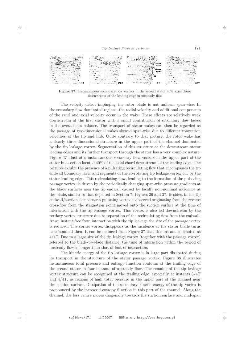
Figure 37. Instantaneous secondary flow vectors in the second stator 40% axial chorddownstream of the leading edge in unsteady flow
The velocity defect impinging the rotor blade is not uniform span-wise. Inthe secondary flow dominated regions, the radial velocity and additional componentsof the swirl and axial velocity occur in the wake. These effects are relatively weekdownstream of the first stator with a small contribution of secondary flow lossesin the overall loss balance. The transport of stator wakes can then be regarded asthe passage of two-dimensional wakes skewed span-wise due to different convectionvelocities at the tip and hub. Quite contrary to that picture, the rotor wake hasa clearly three-dimensional structure in the upper part of the channel dominatedby the tip leakage vortex. Segmentation of this structure at the downstream statorleading edges and its further transport through the stator has a very complex nature.Figure 37 illustrates instantaneous secondary flow vectors in the upper part of thestator in a section located 40% of the axial chord downstream of the leading edge. Thepictures exhibit the presence of a pulsating recirculating flow that encompasses the tipendwall boundary layer and segments of the co-rotating tip leakage vortex cut by thestator leading edge. This recirculating flow, leading to the formation of the pulsatingpassage vortex, is driven by the periodically changing span-wise pressure gradients atthe blade surfaces near the tip endwall caused by locally non-nominal incidence atthe blade, similar to that depicted in Section 7, Figures 26 and 27. Besides, in the tipendwall/suction side corner a pulsating vortex is observed originating from the reversecross-flow from the stagnation point moved onto the suction surface at the time ofinteraction with the tip leakage vortex. This vortex is also fed downstream by thetertiary vortex structure due to separation of the recirculating flow from the endwall.At an instant free from interaction with the tip leakage the size of the passage vortexis reduced. The corner vortex disappears as the incidence at the stator blade turnsnear-nominal then. It can be deduced from Figure 37 that this instant is denoted as4/4T. Due to a large size of the tip leakage vortex (together with the passage vortex)referred to the blade-to-blade distance, the time of interaction within the period ofunsteady flow is longer than that of lack of interaction.
The kinetic energy of the tip leakage vortex is in large part dissipated duringits transport in the structure of the stator passage vortex. Figure 38 illustratesinstantaneous total pressure and entropy function contours at the trailing edge ofthe second stator in four instants of unsteady flow. The remains of the tip leakagevortex structure can be recognised at the trailing edge, especially at instants 3/4Tand 4/4T, as regions of high total pressure in the upper part of the channel nearthe suction surface. Dissipation of the secondary kinetic energy of the tip vortex ispronounced by the increased entropy function in this part of the channel. Along thechannel, the loss centre moves diagonally towards the suction surface and mid-span
tq210r-e/171 11I2007 BOP s.c., http://www.bop.com.pl

172 P. Lampart
Figure 38. Instantaneous total pressure and entropy function contours at the second statortrailing edge in unsteady flow
sections as shown in [56]. The area distributions of total pressure and entropy functionare subject to considerable changes within the period of unsteady flow. Oscillationsdue to interaction of the rotor wake in the lower part of the channel are smaller, butcan also be recognised, especially in the region of hub secondary flow.
Only general tendencies in the process of unsteady interaction of three-dimensional wakes are pointed out in this paper. More detailed analysis will be possi-ble after further developments of the flow solver, particularly concerning the adaptivegrid generation.
9. Conclusions
The sources of flow losses in connection with the tip leakage over shrouded andunshrouded rotor blades were investigated. The theoretical analysis of dissipativeprocess enables the evaluation of leakage losses and determination of parametersthat have an effect on the level of loss. Making use of a number of simplifyingassumptions and a model of lost secondary kinetic energy, leakage loss correlationswere obtained. Validation on experimental cascades shows that these correlations candescribe relatively well the leakage losses.
The effects of geometrical and flow parameters on the development of flowlosses in the leakage-dominated region as well as on the interaction of tip leakage flowwith secondary flows were also investigated using a 3D RANS solver. In the case ofunshrouded free-tip blades, an increase of the tip gap size was found to increase theintensity and size of the tip leakage vortex, decrease the size of the tip passage vortex.The intensity of the passage vortex however increases with the increased flow turningin the cascade and when the incidence at the rotor blade is moved onto the pressuresurface – both in the case of tip and hub vortices. The relative motion of the bladetips and endwall acts to considerably reduce the tip leakage and tip passage vortex.
Main properties of interaction of the shroud leakage with the main flow andsecondary flows were presented. The shroud leakage helps to remove the low-energy
tq210r-e/172 11I2007 BOP s.c., http://www.bop.com.pl

Tip Leakage Flows in Turbines 173
endwall boundary layer into the leakage slots, which retards the development ofsecondary flows in the current blade row. As compared to the case of no leakagecalculations, the leakage flow may locally change the incidence at the blade onto thepressure side and increase the extension of the suction side separation zone. Unlike theleakage over unshrouded blades, the shroud leakage does not form a vortex structureon the re-entry to the blade-to-blade passage, but an axisymmetric mixing zone.The mixing processes are hardly accomplished in the rotor region. The inflow of theleakage stream onto the suction side of the downstream stator and local span-wisepressure gradients at the stator blades induce a strong recirculating flow in the stator.This recirculating flow rolls up both the low-energy endwall boundary layer fluid andhigh-energy mixing zone of the shroud leakage and gives rise to the formation of anintensive tip passage vortex in the stator. Large part of the total pressure surplus inthe leakage region is dissipated in the stator channels. However, the remains of theleakage can still be recognised in the exit section as regions of increased total pressure.
An additional source of loss is unsteady transport of wakes through thedownstream blade row. Transport of a two-dimensional stator wake leads to significantoscillations in size of the secondary flow zones and suction side separation, which canbe explained by local changes of the inlet angle during the time of interaction withthe passing wakes. Oscillations of flow parameters in the tip leakage region are lessimportant. Particularly complex is downstream transport of three-dimensional rotorwakes, which include the tip leakage vortex. The structure of the tip leakage vortexsegmented by the leading edges of the downstream stator is found within the pulsatingrecirculating flow, from which a pulsating passage vortex is formed in the stator. In thetip endwall/suction side corner another pulsating counter-rotating vortex is observedoriginating from the endwall cross-flow from the stagnation point moved onto thesuction side. Large part, but not all of the secondary kinetic energy of the tip leakagevortex is dissipated in the stator channels.
Appendix
In this appendix, enthalpy losses in the stator, rotor and stage are defined.The definitions are gathered in Table A1 and are easily explained with the help ofFigure A1 showing an enthalpy-entropy diagram of the expansion process in a turbinestage.
Table A1. Enthalpy losses in the stator, rotor and stage
Stator loss ξ1=(h1−h1s)/(h0T −h1s)
Rotor loss ξ2=(h2−h2s)/(h1T −h2s)
Stage loss (without exit energy =stator + rotor loss)
ξ12=(h2−h2s′ )/(h0T −h2s′ )
Stage loss (with exit energy =stator + rotor loss + exit energy)
ξ12c=(h2T −h2s′ )/(h0T −h2s′ )
References
[1] Gardzilewicz A and Marcinkowski S 1995 ASME PWR 28 (3) 349[2] Marcinkowski S 1998 Rep. Inst. Fluid Flow Machinery, Gdansk 292 98 (in Polish)
tq210r-e/173 11I2007 BOP s.c., http://www.bop.com.pl

174 P. Lampart
Figure A1. Enthalpy-entropy diagram for a turbine stage
[3] Denton J D 1993 Trans. ASME J. Turbomachinery 115 621
[4] Bindon J P 1987 I. Mech. E. Paper C273 87
[5] Bindon J P 1989 Trans. ASME J. Turbomachinery 111 257
[6] Sjolander S A and Amrud K K 1987 Trans. ASME J. Turbomachinery 109 237
[7] Sjolander S A and Cao D 1995 Trans. ASME J. Turbomachinery 117 578
[8] Yaras M I, Zhu Y and Sjolander S A 1989 Trans. ASME J. Turbomachinery 111 276
[9] Graham J A H 1986 Trans. ASME J. Engng Gas Turbines Power 108 38
[10] Xiao X, McCarter A A and Lakshminarayana B 2000 ASME Pap. 2000-GT-0476
[11] Xiao X, McCarter A A and Lakshminarayana B 2000 ASME Pap. 2000-GT-0477
[12] Sjolander S A 1997 VKI LS 1997-01
[13] Moore J and Tilton J S 1988 Trans. ASME J. Turbomachinery 110 18
[14] Yaras M I and Sjolander S A 1990 Trans. ASME J. Turbomachinery 112 609
[15] Tallman J and Lakshminarayana B 2000 ASME Pap. 2000-GT-0514
[16] Tallman J and Lakshminarayana B 2000 ASME Pap. 2000-GT-0516
[17] Yamamoto A 1988 Trans. ASME J. Turbomachinery 110 329
[18] Yamamoto A 1989 Trans. ASME J. Turbomachinery 111 264
[19] Yamamoto A, Matsyunuma T and Outa E 2001 Three-dimensional Flows and Losses in anUltra-highly Loaded Turbine, Rep. National Aerospace Lab., Tokyo, Japan
[20] Chan J K K, Yaras M I and Sjolander S A 1994 ASME Pap. 94-GT-250
[21] Moore J G, Schorn S A and Moore J 1996 Trans. ASME J. Turbomachinery 118 622
[22] Heyes F J G, Hodson H P and Dailey G M 1992 Trans. ASME J. Turbomachinery 114 643
[23] Lampart P, Gardzilewicz A, Szymaniak M, Kurant B, Banaszkiewicz M and Malec A 2003Trans. IFFM 114 19
[24] Boletis E and Sieverding C H 1991 Trans. ASME J. Turbomachinery 113 1
[25] Morphis G and Bindon J P 1994 ASME Pap. 94-GT-481
[26] Yaras M I and Sjolander S A 1992 Trans. ASME J. Turbomachinery 114 204
[27] Ainley D G and Mathieson G C R 1951 ARC R&M Rep. 2891
[28] Dunham J and Came P M 1970 Trans ASME, J. Eng. Power 92 (3) 252
[29] Kacker S C and Okapuu U 1982 Trans. ASME J. Engng Power 104 111
[30] Yaras M I and Sjolander S A 1992 Trans. ASME J. Turbomachinery 114 652
tq210r-e/174 11I2007 BOP s.c., http://www.bop.com.pl

Tip Leakage Flows in Turbines 175
[31] Dishart P T and Moore J 1990 Trans. ASME J. Turbomachinery 112 599[32] Kim B N and Chung M K 1997 Trans. ASME J. Turbomachinery 119 399[33] Heyes F J G and Hodson H P 1993 Trans. ASME J. Turbomachinery 115 373[34] Yaras M I, Sjolander S A and King R J 1992 Trans. ASME J. Turbomachinery 114 660[35] Yershov S and Rusanov A 1997 The Application Package FlowER for the Calculation of 3DViscous Flows Through Multi-stage Machinery, Certificate of Registration of Copyright,Ukrainian State Agency of Copyright and Related Rights, Kiev
[36] Yershov S, Rusanov A, Gardzilewicz A, Lampart P and Świrydczuk J 1998 TASK Quart. 2(2) 319
[37] Lampart P, Świrydczuk J and Gardzilewicz A 2001 TASK Quart. 5 (2) 191[38] Gier J, Stubert B, Brouillet B and de Vito L 2003 ASME Pap. GT2003-38025[39] Kosowski K 1995 The Optimum Values of the Main Design Parameters of Turbine Stages.The Generalised Design Method of Turbine Stages, Zeszyty Naukowe Politechniki Gdańskiej,Budownictwo Okrętowe LXII, No. 528 (in Polish)
[40] Lampart P, Gardzilewicz A, Yershov S and Rusanov A 2000 ASME Pap. IJPGC2000-15004[41] Lampart P, Gardzilewicz A, Yershov S and Rusanov A 2001 J. Thermal Science 10 (3) 198[42] Lampart P, Yershov S, Rusanov A and Szymaniak M 2004 ASME Pap. GT2004-53882[43] Gibboni A, Menter J R, Peters P, Wolter K, Pfost H and Breisig V 2003 ASME Pap.
GT2003-38722[44] Błażko E and Lidke M 1996 TUR-96 – Computer Programme for Heat-and-Flow Calculationsof Turbine Blading Systems of Given Geometry, Opr. Diagnostyka Maszyn sp. z o.o., Gdansk,No. 21/96 (in Polish)
[45] Peters P, Breisig V, Giboni A, Lerner C and Pfost H 2000 ASME Pap. 2000-GT-478[46] Wallis A M, Denton J D and Demargne A A J 2000 ASME Pap. 2000-GT-475[47] Rusanov A V and Yershov S V 1977 Proc. Int. Conf. Modelling and Design in Fluid-FlowMachinery, Gdansk, Poland, pp. 153–160
[48] Lampart P, Rusanov A, Yershov S, Świrydczuk J and Gardzilewicz A 1999 Cieplne MaszynyPrzepływowe 115 285
[49] Walraevens R and Gallus H E 1999 Rep. Institute of Jet Propulsion and Turbomachinery,RWTH Aachen
[50] Kerrebrock J L and Mikolajczak A A 1970 Trans. ASME J. Engng Power 92 359[51] Mayle R E and Dullenkopf K 1989 Trans. ASME J. Turbomachinery 111 188[52] Wierciński Z 1999 Wake Induced Laminar-turbulent Transition in the Boundary Layer,Zeszyty Naukowe IMP PAN, No. 499/1450/99 (in Polish)
[53] Elsner W, Vilmin S, Drobniak S and Piotrowski W 2004 ASME Pap. GT2004-53757[54] Lampart P 2006 Numerical Investigations of Aerodynamics of Turbine Blading Systems,Zeszyty Naukowe IMP PAN (in print; in Polish)
[55] Stephan B, Gallus H and Niehuis R 2000 ASME Pap. 2000-GT-613[56] Lampart P, Rusanov A, Yershov S, Gardzilewicz A and Badur J 1999 Proc. VI ERCOFTACSeminar and Workshop on 3D Turbomachinery Flow Prediction, Aussois, France
tq210r-e/175 11I2007 BOP s.c., http://www.bop.com.pl

176 TASK QUARTERLY 10 No 2
tq210r-e/176 11I2007 BOP s.c., http://www.bop.com.pl