
Opioid receptor desensitization: mechanisms and its link ...
CC-63
TIP DESENSITIZATION OF AN AXIAL TURBINE ROTOR
USING PARTIAL SQUEALER RIMS
Debashis Dey1, Levent Kavurmacioglu2 & Cengiz Camci3
Department of Aerospace Engineering Turbomachinery Heat Transfer Laboratory
The Pennsylvania State University University Park, PA 16802
[email protected] http://www.personal.psu.edu/cxc11/
Abstract
This paper deals with an experimental investigation of aerodynamic characteristics of full and partial-length squealer rims in a turbine stage. Full and partial-length squealer rims are investigated separately on the pressure side and on the suction side in the “Axial Flow Turbine Research Facility” (AFTRF) of the Pennsylvania State University. The streamwise length of these “partial squealer tips” and their chordwise position are varied to find an optimal aerodynamic tip configuration. The optimal configuration in this cold turbine study is defined as the one that is minimizing the stage exit total pressure defect in the tip vortex dominated zone. A new “channel arrangement” diverting some of the leakage flow into the trailing edge zone is also studied. Current results indicate that the use of “partial squealer rims” in axial flow turbines can positively affect the local aerodynamic field by weakening the tip leakage vortex. Results also show that the suction side partial squealers are aerodynamically superior to the pressure side squealers and the channel arrangement. The suction side partial squealers are capable of reducing the stage exit total pressure defect associated with the tip leakage flow to a significant degree.
INTRODUCTION The gap required between the tips of rotating blades and the stationary casing of an axial flow turbine is a significant source of inefficiency. The leakage flow mainly induced by the pressure differential between the pressure side and suction side of a rotor tip usually rolls into a streamwise vortical structure. Total pressure losses of this flow structure measured at the exit of a turbine stage are directly proportional with the tip gap height. The leakage flow mixing with the rotor passage flow causes total pressure loss and significantly reduces turbine stage efficiency. Tip leakage related losses might account for as much as a third of the aerodynamic losses in a stage. Early tip leakage flow visualization experiments in water led to the observation of the typical separation bubble near the entrance section of the gap. These studies concluded that viscous flow contributions could probably be ignored because of the magnitude of Reynolds number in the tip gap. Additional visualizations showed that the casing boundary layers changed the pressure field in the gap so much that rotational effects
_________________________________________________________________________________ 1 Research Assistant, currently at GE Global Research Center, Schenectady, New York 2 Visiting Professor, currently at Istanbul Technical University, Mech.Eng.Dept., Turkey 3 Professor of Aerospace Engineering, Pennsylvania State University
CC-64
could not be ignored for an accurate determination of leakage losses. The rotation does have a very significant impact on the aerodynamic structure of tip clearance flows in turbomachinery systems. The acceleration of the flow into the entrance region of the tip gap near the pressure side results in the re-laminarization of an otherwise turbulent tip surface boundary layer. A number of investigators measured heat transfer coefficients on the tip surface by using a moving outer casing. They claimed that different rotational speeds imposed significant shear layer variations only near the outer casing. Flow features controlling the local tip heat transfer were not influenced from the rotation dependent shear layer near the outer casing. Heyes and Hodson [1] reported an iterative two-dimensional method of solving the mass flow through the tip gap. Their experimentally confirmed results showed that the chordwise pressure gradients had a significant influence on the separation zone and the mass flow rate through the gap region. Another set of experiments from Sjolander and Cao in [2] supported Heyes and Hodson tip gap flow model, emphasizing the importance of having realistic chordwise pressure gradients. Their model was characterized by a vena-contracta forming a uniform isentropic jet along the endwall and a wake-mixing region along the blade tip surface downstream of the separation bubble. The main flow near the vena-contracta suffered very little loss. High losses were generated in the shear flow zone near the surface of the separation bubble. Morphis and Bindon [3] performed an annular cascade experiment with a rotating outer casing. They found that the width of the separation bubble was directly controlled by the tip gap height. They experimentally confirmed that motion of the outer casing in the opposite direction to the tip gap flow reduced the leakage mass flow rate and momentum. The size of the separation bubble was reduced when the outer casing motion was imposed. The effect of tip gap size and turbulence intensity on heat transfer distribution was investigated in a five bladed linear cascade by Azad, Han, Teng and Boyle [4]. They measured relatively high heat transfer near the entrance section of the gap near the pressure side because of the flow entrance effect. A larger tip gap generally resulted in a higher overall heat transfer coefficient because of the increase in the magnitude of the tip leakage flow. A 15-20 % increase in heat transfer level along the leakage flow path resulted when the free stream turbulence intensity level was increased from 6.1 % to 9.7 %.
A new tip desensitization method based on a pressure side tip extension was discussed in Dey and Camci [5]. Phase-averaged total pressure maps downstream of the rotor showed the tip vortex leakage related local flow modifications. The rotating turbine study indicated that the momentum defect in the tip vortex of an untreated turbine blade tip could be effectively reduced by a suggested “pressure side tip platform extension”. Squealer Tips: The function of a conventional squealer tip design is three fold. The squealer tip provides an effective reduction in tip gap flow. The specific approach also protects the blade tip from the full impact of high temperature leakage gases. A third function of this design approach is its protective ability against incidental rubs. A conventional full squealar approach forms an enclosed cavity over the blade tip as shown by Anderson [6]. This is actually a simple labyrinth seal configuration between the turbine casing and rotating blade tip. Azad, Han and Boyle [7] also investigated heat transfer and flow characteristics on the squealer tip of a gas turbine blade representative of E3 design. They found a higher heat transfer coefficient on the rim surface because of the entrance and exit effects. The measured heat transfer coefficient is much lower in the mid-chord toward the pressure side and downstream end of the cavity when compared to the flat tip case. The heat transfer coefficient in a squealer tip is higher near the central upstream end of the cavity and the trailing edge region. They concluded that the squealer tip provides an overall lower heat transfer coefficient when compared to the flat tip case.
Heyes, Hodson and Daily [8] studied two squealer tip configurations in a cascade configuration and compared these to a flat baseline tip configuration. They showed the potential of squealer tip geometry
CC-65
to reduce tip clearance loss convincingly. Suction side squealer configuration provided the greatest gains in terms of eliminating leakage flow losses.
Variations of known squealer tip configurations may provide an effective aerodynamic seal in the turbine tip gap region. The implementation of chordwise sealing strips on a turbine tip was presented by Bunker and Bailey [9]. A numerical heat transfer investigation of a turbine tip section with a mean camber-line strip was investigated by Ameri [10] for a large power-generating turbine. A radiused-edge tip and a sharp-edge tip were investigated with a mean camber-line strip on the tip surface. The favorable conditions created by using a sharp edge tip were shown. Effects of a squealer tip covering the complete perimeter on rotor heat transfer and efficiency was presented in a numerical study by Ameri, Steinthorsson and Rigby [11].
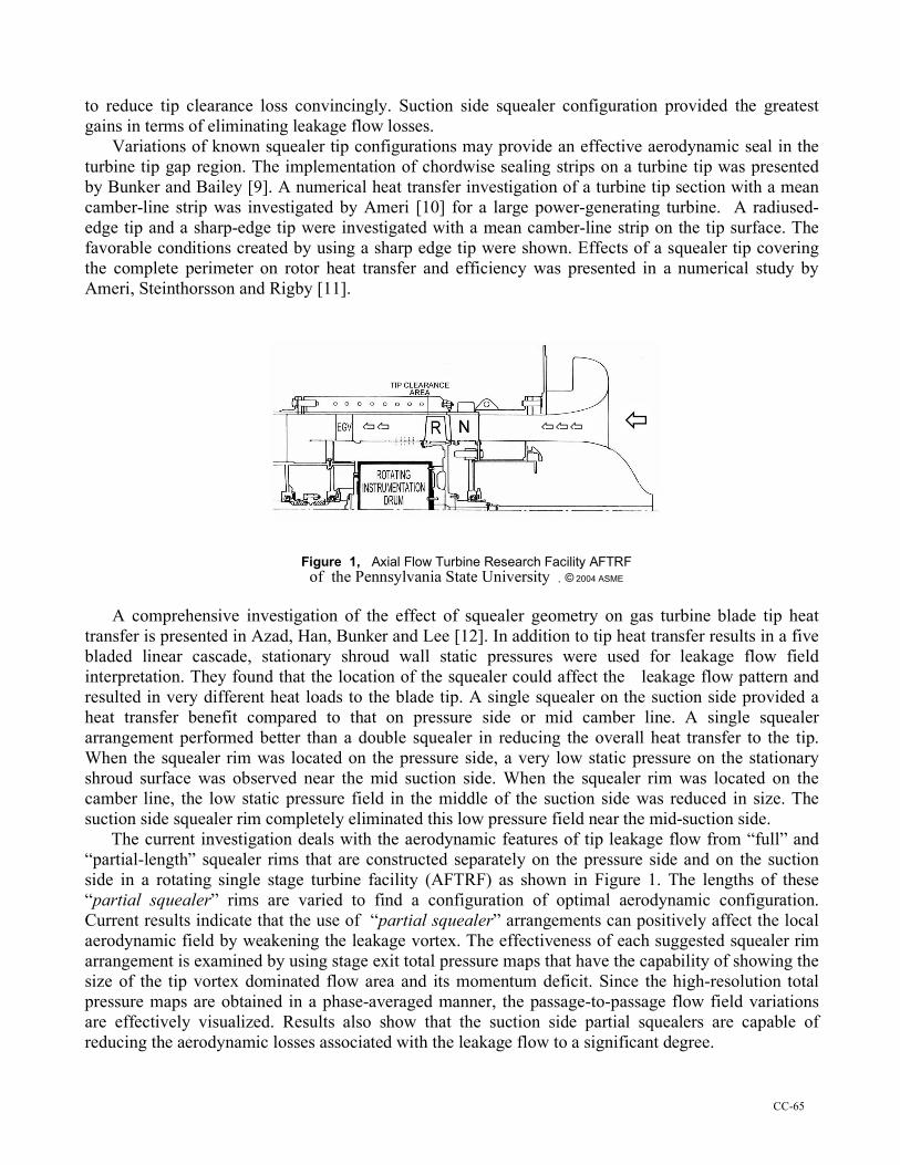
Figure 1, Axial Flow Turbine Research Facility AFTRF
of the Pennsylvania State University , © 2004 ASME A comprehensive investigation of the effect of squealer geometry on gas turbine blade tip heat
transfer is presented in Azad, Han, Bunker and Lee [12]. In addition to tip heat transfer results in a five bladed linear cascade, stationary shroud wall static pressures were used for leakage flow field interpretation. They found that the location of the squealer could affect the leakage flow pattern and resulted in very different heat loads to the blade tip. A single squealer on the suction side provided a heat transfer benefit compared to that on pressure side or mid camber line. A single squealer arrangement performed better than a double squealer in reducing the overall heat transfer to the tip. When the squealer rim was located on the pressure side, a very low static pressure on the stationary shroud surface was observed near the mid suction side. When the squealer rim was located on the camber line, the low static pressure field in the middle of the suction side was reduced in size. The suction side squealer rim completely eliminated this low pressure field near the mid-suction side. The current investigation deals with the aerodynamic features of tip leakage flow from “full” and “partial-length” squealer rims that are constructed separately on the pressure side and on the suction side in a rotating single stage turbine facility (AFTRF) as shown in Figure 1. The lengths of these “partial squealer” rims are varied to find a configuration of optimal aerodynamic configuration. Current results indicate that the use of “partial squealer” arrangements can positively affect the local aerodynamic field by weakening the leakage vortex. The effectiveness of each suggested squealer rim arrangement is examined by using stage exit total pressure maps that have the capability of showing the size of the tip vortex dominated flow area and its momentum deficit. Since the high-resolution total pressure maps are obtained in a phase-averaged manner, the passage-to-passage flow field variations are effectively visualized. Results also show that the suction side partial squealers are capable of reducing the aerodynamic losses associated with the leakage flow to a significant degree.
CC-66
APPARATUS Turbine Research Facility: The Penn State Axial Flow Turbine Research Facility, shown in Figure 1 is an open circuit rotating facility with a bell-mouth inlet of 1.1 m diameter which smoothly contracts the flow to a test section of 0.916 m (36 inch) diameter. The test section consists of a constant diameter outer casing, housing a single turbine stage with 23 nozzle guide vanes and 29 rotor blades. The flow passage height between the cylindrical hub surface and the outer casing is about 0.123 m. The rotor has an axial chord c=0.129 m at the tip. The total-to-total efficiency of the baseline turbine is 0.893. The nozzle efficiency is 0.994 and the rotor efficiency is 0.882. The stage inlet to exit total pressure ratio is 1.0778 at a mass flow rate of 10.53 kg/sec. The nominal rotational speed of the turbine rotor is 1320 rpm. Details about the stage, velocity triangles, blade design, as well as the turbine facility, are given in Lakshminarayana, Camci, Halliwell and Zaccaria [13]. Aerodynamic Instrumentation: Aerodynamic instrumentation available to the facil ity for steady state measurements includes sensors for the measurement of inlet temperature, total and static pressures, flow velocity and flow direction. The facility has provisions to perform aerodynamic shear stress, hot wire, hot film and dynamic pressure measurements in the stage. A probe traverse mechanism (radial and circumferential) is mounted inside the rotating instrumentation drum for the measurements to be performed in the rotating frame of reference. Time Accurate Total Pressure Measurements: The present study uses a fast response, temperature compensated dynamic pressure transducer, XCS-062, made by Kulite Semiconductors . The transducer having a 150 kHz response time is flush mounted at the tip of the probe holder in order to eliminate the time response canceling effects of a cavity with finite volume. The diameter of the dynamic pressure transducer is 1.59 mm (0.063 inch). The transducer is housed in a probe tip section having a diameter of 2.4 mm. The total pressure probe is mounted on the outer casing in the stationary frame. The reference port of the differential transducer is open to atmospheric pressure in the lab. A mapping of the rotor including all twenty nine rotor passages, at the 30 % chord (downstream) location is possible by using a phase averaged total pressure measurements. A turbine shaft encoder triggers the data acquisition system. A total of 2000 samples, at an acquisition rate of 40 kHz, is collected once a trigger pulse is received. Hence, there are 62 data points in each blade passage. Slightly more than one revolution of the rotor is covered in a 2000 sample long data acquisition file. These data constitute an ensemble. Two hundred of such ensembles are averaged at a given radius, and radial position of the probe is changed by a computer-controlled system once the ensemble-averaged data are recorded. Other details of the time accurate total presure probe and the data acquisition system is given in Dey [14] Measurement Grid: The measurement grid extends from 0.17h to 0.96h in steps of 0.013h (0.0016 m). The data acquisition board controls a stepper motor that actuates the probe traverse mechanism in the radial direction. There is no need for a circumferential traverse because the probe in a stationary frame sees each one of the 29 tip vortices in each passage approximately 22 times a second. Signal conditioning is provided by a high-speed amplifier followed by an anti-aliasing filter which is set at about 15 times the blade passing frequency. A complete high-resolution mapping of the total pressure field requires only 30 minutes of turbine run time. Tip Clearance: Although the turbine rotor tips are machined on a precision lathe there is a slight variation of tip clearance from one blade to another. The maximum measured tip gap size is 1.12 mm (t/h=0.91%) and the minimum gap size is 0.81 mm (t/h=0.66%). The nominal tip clearance of the rotor blades defined as the arithmetic average of 29 values from each blade is 0.98 mm (t/h=0.80%). A typical radius of the blade tip corners in AFTRF is about 0.10 millimeter. Since the current tip desensitization study requires many tip region modifications, a special “test blade” was machined down to a relatively large tip gap of 1.65 mm (t/h=1.34%). Since the
CC-67
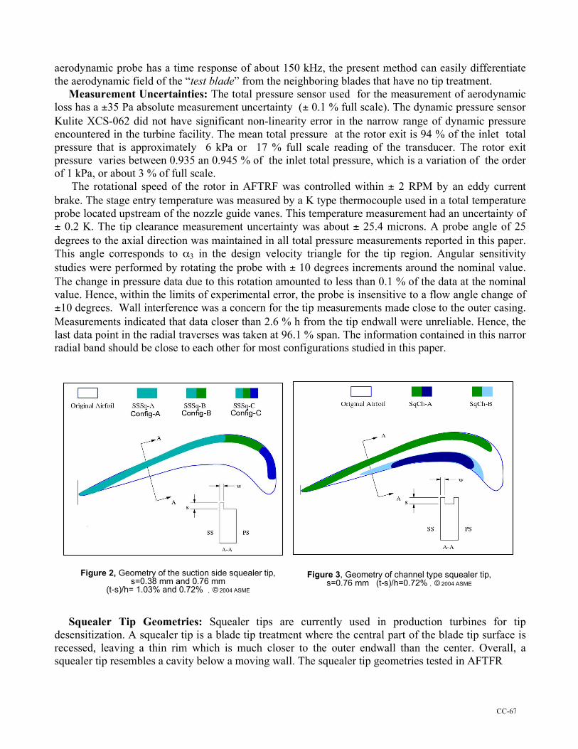
aerodynamic probe has a time response of about 150 kHz, the present method can easily differentiate the aerodynamic field of the “test blade” from the neighboring blades that have no tip treatment. Measurement Uncertainties: The total pressure sensor used for the measurement of aerodynamic loss has a ±35 Pa absolute measurement uncertainty (± 0.1 % full scale). The dynamic pressure sensor Kulite XCS-062 did not have significant non-linearity error in the narrow range of dynamic pressure encountered in the turbine facility. The mean total pressure at the rotor exit is 94 % of the inlet total pressure that is approximately 6 kPa or 17 % full scale reading of the transducer. The rotor exit pressure varies between 0.935 an 0.945 % of the inlet total pressure, which is a variation of the order of 1 kPa, or about 3 % of full scale. The rotational speed of the rotor in AFTRF was controlled within ± 2 RPM by an eddy current brake. The stage entry temperature was measured by a K type thermocouple used in a total temperature probe located upstream of the nozzle guide vanes. This temperature measurement had an uncertainty of ± 0.2 K. The tip clearance measurement uncertainty was about ± 25.4 microns. A probe angle of 25 degrees to the axial direction was maintained in all total pressure measurements reported in this paper. This angle corresponds to α3 in the design velocity triangle for the tip region. Angular sensitivity studies were performed by rotating the probe with ± 10 degrees increments around the nominal value. The change in pressure data due to this rotation amounted to less than 0.1 % of the data at the nominal value. Hence, within the limits of experimental error, the probe is insensitive to a flow angle change of ±10 degrees. Wall interference was a concern for the tip measurements made close to the outer casing. Measurements indicated that data closer than 2.6 % h from the tip endwall were unreliable. Hence, the last data point in the radial traverses was taken at 96.1 % span. The information contained in this narror radial band should be close to each other for most configurations studied in this paper. Squealer Tip Geometries: Squealer tips are currently used in production turbines for tip desensitization. A squealer tip is a blade tip treatment where the central part of the blade tip surface is recessed, leaving a thin rim which is much closer to the outer endwall than the center. Overall, a squealer tip resembles a cavity below a moving wall. The squealer tip geometries tested in AFTFR
Figure 2, Geometry of the suction side squealer tip,
s=0.38 mm and 0.76 mm (t-s)/h= 1.03% and 0.72% , © 2004 ASME
Figure 3, Geometry of channel type squealer tip, s=0.76 mm (t-s)/h=0.72% , © 2004 ASME
CC-68
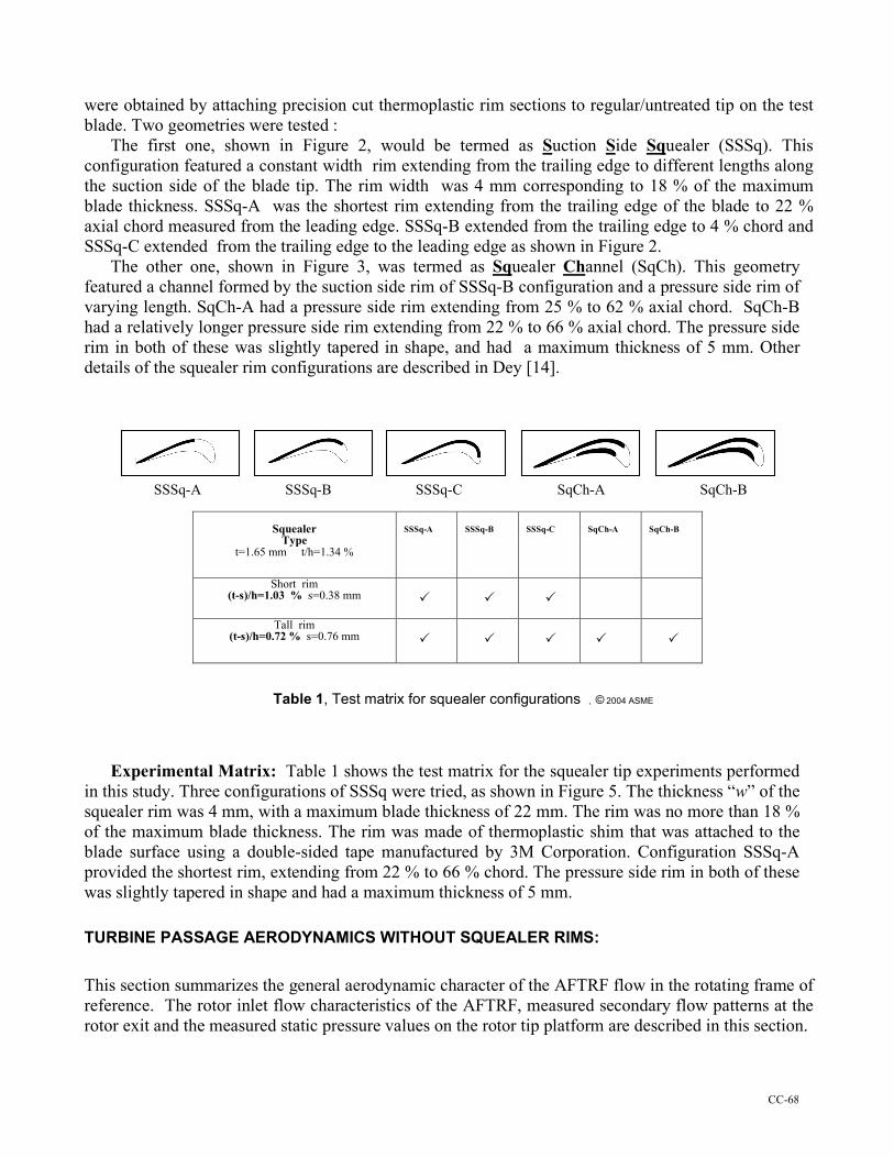
were obtained by attaching precision cut thermoplastic rim sections to regular/untreated tip on the test blade. Two geometries were tested : The first one, shown in Figure 2, would be termed as Suction Side Squealer (SSSq). This configuration featured a constant width rim extending from the trailing edge to different lengths along the suction side of the blade tip. The rim width was 4 mm corresponding to 18 % of the maximum blade thickness. SSSq-A was the shortest rim extending from the trailing edge of the blade to 22 % axial chord measured from the leading edge. SSSq-B extended from the trailing edge to 4 % chord and SSSq-C extended from the trailing edge to the leading edge as shown in Figure 2. The other one, shown in Figure 3, was termed as Squealer Channel (SqCh). This geometry featured a channel formed by the suction side rim of SSSq-B configuration and a pressure side rim of varying length. SqCh-A had a pressure side rim extending from 25 % to 62 % axial chord. SqCh-B had a relatively longer pressure side rim extending from 22 % to 66 % axial chord. The pressure side rim in both of these was slightly tapered in shape, and had a maximum thickness of 5 mm. Other details of the squealer rim configurations are described in Dey [14]. SSSq-A SSSq-B SSSq-C SqCh-A SqCh-B
Squealer
Type t=1.65 mm t/h=1.34 %
SSSq-A
SSSq-B
SSSq-C
SqCh-A
SqCh-B
Short rim (t-s)/h=1.03 % s=0.38 mm
Tall rim (t-s)/h=0.72 % s=0.76 mm
Table 1, Test matrix for squealer configurations , © 2004 ASME Experimental Matrix: Table 1 shows the test matrix for the squealer tip experiments performed in this study. Three configurations of SSSq were tried, as shown in Figure 5. The thickness “w” of the squealer rim was 4 mm, with a maximum blade thickness of 22 mm. The rim was no more than 18 % of the maximum blade thickness. The rim was made of thermoplastic shim that was attached to the blade surface using a double-sided tape manufactured by 3M Corporation. Configuration SSSq-A provided the shortest rim, extending from 22 % to 66 % chord. The pressure side rim in both of these was slightly tapered in shape and had a maximum thickness of 5 mm. TURBINE PASSAGE AERODYNAMICS WITHOUT SQUEALER RIMS: This section summarizes the general aerodynamic character of the AFTRF flow in the rotating frame of reference. The rotor inlet flow characteristics of the AFTRF, measured secondary flow patterns at the rotor exit and the measured static pressure values on the rotor tip platform are described in this section.
CC-69
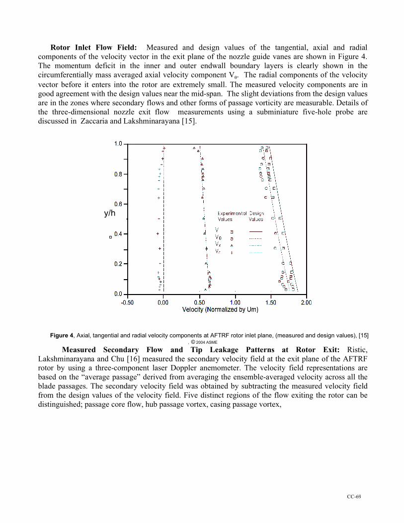
Rotor Inlet Flow Field: Measured and design values of the tangential, axial and radial components of the velocity vector in the exit plane of the nozzle guide vanes are shown in Figure 4. The momentum deficit in the inner and outer endwall boundary layers is clearly shown in the circumferentially mass averaged axial velocity component Vθ. The radial components of the velocity vector before it enters into the rotor are extremely small. The measured velocity components are in good agreement with the design values near the mid-span. The slight deviations from the design values are in the zones where secondary flows and other forms of passage vorticity are measurable. Details of the three-dimensional nozzle exit flow measurements using a subminiature five-hole probe are discussed in Zaccaria and Lakshminarayana [15].
Figure 4, Axial, tangential and radial velocity components at AFTRF rotor inlet plane, (measured and design values), [15] , © 2004 ASME
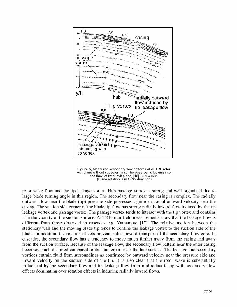
Measured Secondary Flow and Tip Leakage Patterns at Rotor Exit: Ristic, Lakshminarayana and Chu [16] measured the secondary velocity field at the exit plane of the AFTRF rotor by using a three-component laser Doppler anemometer. The velocity field representations are based on the “average passage” derived from averaging the ensemble-averaged velocity across all the blade passages. The secondary velocity field was obtained by subtracting the measured velocity field from the design values of the velocity field. Five distinct regions of the flow exiting the rotor can be distinguished; passage core flow, hub passage vortex, casing passage vortex,
y/h
CC-70
rotor wake flow and the tip leakage vortex. Hub passage vortex is strong and well organized due to large blade turning angle in this region. The secondary flow near the casing is complex. The radially outward flow near the blade (tip) pressure side possesses significant radial outward velocity near the casing. The suction side corner of the blade tip flow has strong radially inward flow induced by the tip leakage vortex and passage vortex. The passage vortex tends to interact with the tip vortex and contains it in the vicinity of the suction surface. AFTRF rotor field measurements show that the leakage flow is different from those observed in cascades e.g. Yamamoto [17]. The relative motion between the stationary wall and the moving blade tip tends to confine the leakage vortex to the suction side of the blade. In addition, the rotation effects prevent radial inward transport of the secondary flow core. In cascades, the secondary flow has a tendency to move much further away from the casing and away from the suction surface. Because of the leakage flow, the secondary flow pattern near the outer casing becomes much distorted compared to its counterpart near the hub surface. The leakage and secondary vortices entrain fluid from surroundings as confirmed by outward velocity near the pressure side and inward velocity on the suction side of the tip. It is also clear that the rotor wake is substantially influenced by the secondary flow and tip leakage flow from mid-radius to tip with secondary flow effects dominating over rotation effects in inducing radially inward flows.
Figure 5, Measured secondary flow patterns at AFTRF rotor exit plane without squealer rims. The observer is looking into
the flow at rotor exit plane, [16] , © 2004 ASME (Blade rotation is in CCW direction)
CC-71
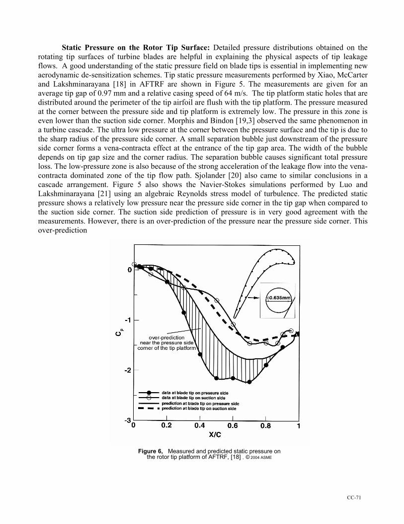
Static Pressure on the Rotor Tip Surface: Detailed pressure distributions obtained on the rotating tip surfaces of turbine blades are helpful in explaining the physical aspects of tip leakage flows. A good understanding of the static pressure field on blade tips is essential in implementing new aerodynamic de-sensitization schemes. Tip static pressure measurements performed by Xiao, McCarter and Lakshminarayana [18] in AFTRF are shown in Figure 5. The measurements are given for an average tip gap of 0.97 mm and a relative casing speed of 64 m/s. The tip platform static holes that are distributed around the perimeter of the tip airfoil are flush with the tip platform. The pressure measured at the corner between the pressure side and tip platform is extremely low. The pressure in this zone is even lower than the suction side corner. Morphis and Bindon [19,3] observed the same phenomenon in a turbine cascade. The ultra low pressure at the corner between the pressure surface and the tip is due to the sharp radius of the pressure side corner. A small separation bubble just downstream of the pressure side corner forms a vena-contracta effect at the entrance of the tip gap area. The width of the bubble depends on tip gap size and the corner radius. The separation bubble causes significant total pressure loss. The low-pressure zone is also because of the strong acceleration of the leakage flow into the vena-contracta dominated zone of the tip flow path. Sjolander [20] also came to similar conclusions in a cascade arrangement. Figure 5 also shows the Navier-Stokes simulations performed by Luo and Lakshminarayana [21] using an algebraic Reynolds stress model of turbulence. The predicted static pressure shows a relatively low pressure near the pressure side corner in the tip gap when compared to the suction side corner. The suction side prediction of pressure is in very good agreement with the measurements. However, there is an over-prediction of the pressure near the pressure side corner. This over-prediction
Figure 6, Measured and predicted static pressure on the rotor tip platform of AFTRF, [18] , © 2004 ASME
CC-72
may be attributed to the relatively complex tip gap inlet velocity with radially outward components. The existence of a separation bubble near the pressure side corner complicates this highly three dimensional leakage flow pattern. The predictions match the measurements of tip platform pressure well in the last 20 percent axial chord of the blade where pressure side and suction side corner pressures are close to each other. EXPERIMENTAL RESULTS WITH PARTIAL SQUEALER RIM ARRANGEMENTS AND DISCUSSION:
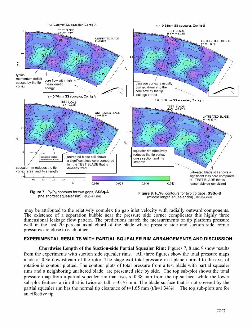
Chordwise Length of the Suction-side Partial Squealer Rim: Figures 7, 8 and 9 show results from the experiments with suction side squealer rims. All three figures show the total pressure maps made at 0.3c downstream of the rotor. The stage exit total pressure in a plane normal to the axis of rotation is contour plotted. The contour plots of total pressure from a test blade with partial squealer rims and a neighboring unaltered blade are presented side by side. The top sub-plot shows the total pressure map from a partial squealer rim that rises s=0.38 mm from the tip surface, while the lower sub-plot features a rim that is twice as tall, s=0.76 mm. The blade surface that is not covered by the partial squealer rim has the normal tip clearance of t=1.65 mm (t/h=1.34%). The top sub-plots are for an effective tip
typical momentum deficit caused by the tip vortex
core flow with high mean kinetic energy
squealer rim reduces the tip vortex area and its strength
passage vortex near the hub wall
passage vortex is usually pushed down into the core flow by the tip leakage vortex
squealer rim effectively reduces the tip vortex cross section and its strength
untreated blade still shows a significant loss core compared to TEST BLADE that is reasonably de-sensitized
untreated blade still shows a significant loss core compared to the TEST BLADE that is de-sensitized
Figure 8, Po/Pin contours for two tip gaps, SSSq-B (middle length squealer rim) , © 2004 ASME
Figure 7, Po/Pin contours for two gaps, SSSq-A (the shortest squealer rim) , © 2004 ASME
CC-73
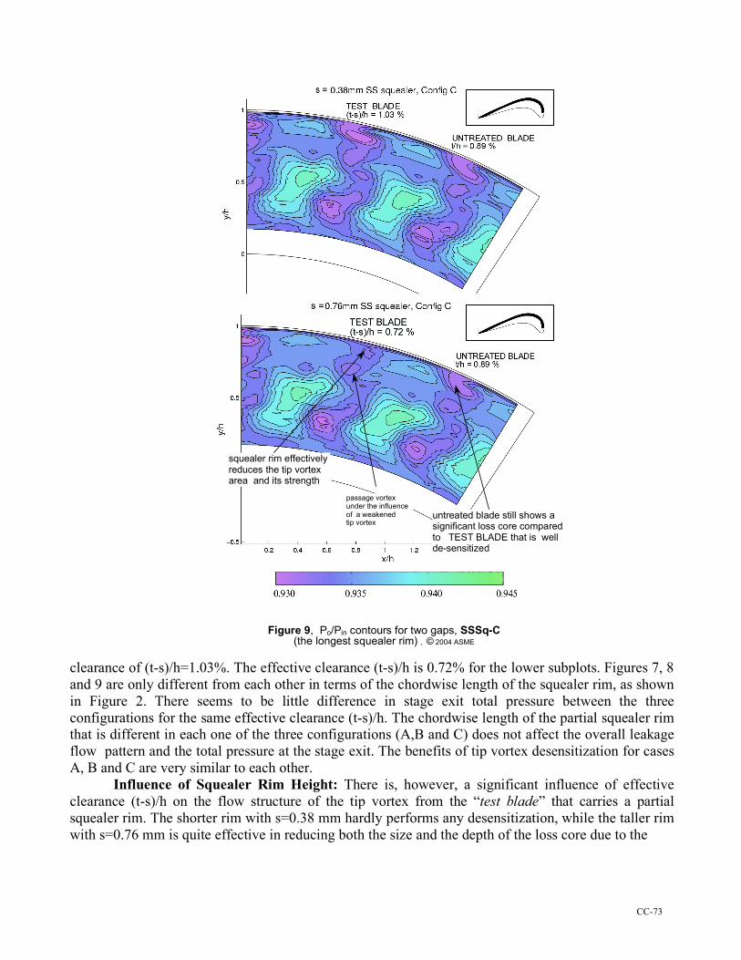
Figure 9, Po/Pin contours for two gaps, SSSq-C (the longest squealer rim) , © 2004 ASME
clearance of (t-s)/h=1.03%. The effective clearance (t-s)/h is 0.72% for the lower subplots. Figures 7, 8 and 9 are only different from each other in terms of the chordwise length of the squealer rim, as shown in Figure 2. There seems to be little difference in stage exit total pressure between the three configurations for the same effective clearance (t-s)/h. The chordwise length of the partial squealer rim that is different in each one of the three configurations (A,B and C) does not affect the overall leakage flow pattern and the total pressure at the stage exit. The benefits of tip vortex desensitization for cases A, B and C are very similar to each other.
Influence of Squealer Rim Height: There is, however, a significant influence of effective clearance (t-s)/h on the flow structure of the tip vortex from the “test blade” that carries a partial squealer rim. The shorter rim with s=0.38 mm hardly performs any desensitization, while the taller rim with s=0.76 mm is quite effective in reducing both the size and the depth of the loss core due to the
squealer rim effectively reduces the tip vortex area and its strength
passage vortex under the influence of a weakened tip vortex
untreated blade still shows a significant loss core compared to TEST BLADE that is well de-sensitized
CC-74
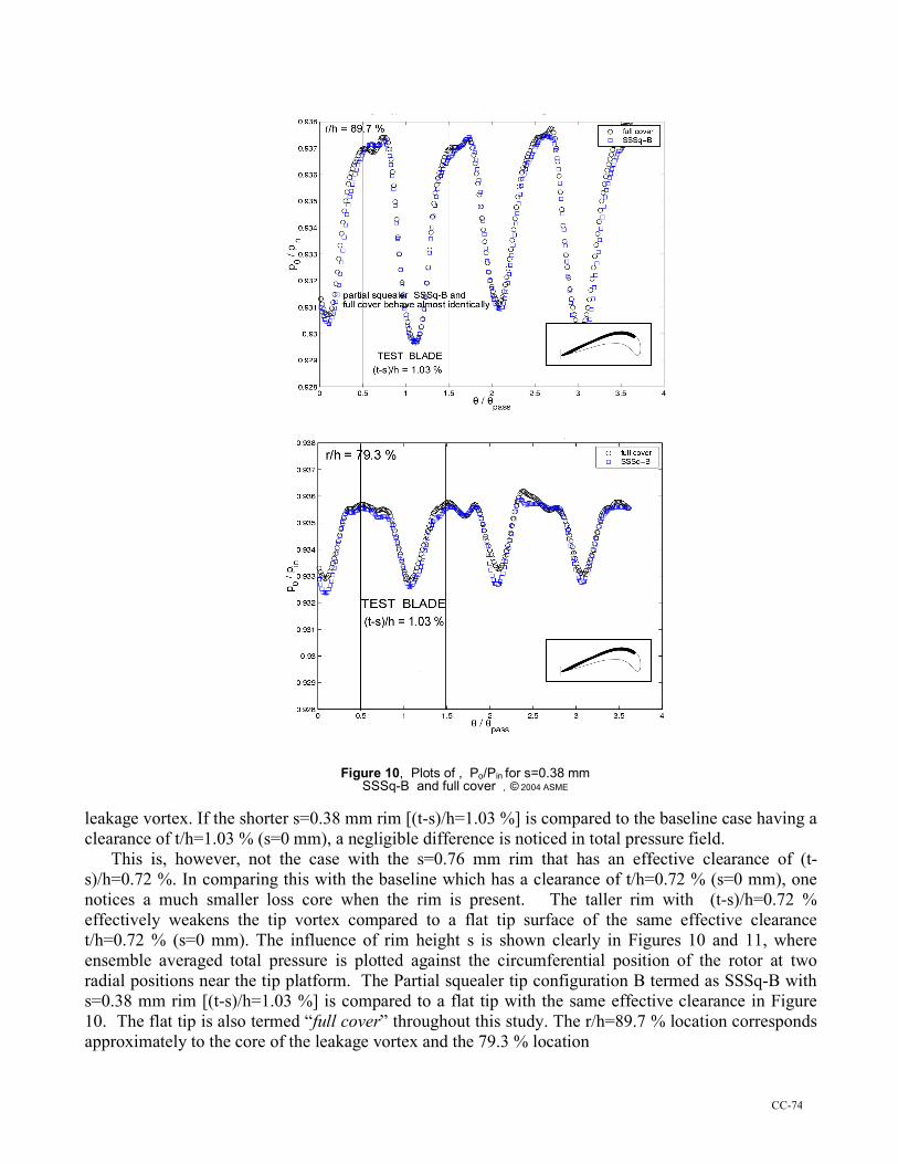
Figure 10, Plots of , Po/Pin for s=0.38 mm SSSq-B and full cover , © 2004 ASME
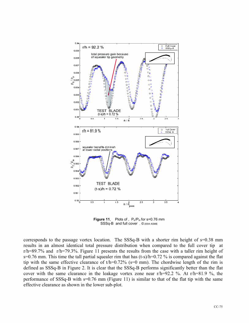
leakage vortex. If the shorter s=0.38 mm rim [(t-s)/h=1.03 %] is compared to the baseline case having a clearance of t/h=1.03 % (s=0 mm), a negligible difference is noticed in total pressure field. This is, however, not the case with the s=0.76 mm rim that has an effective clearance of (t-s)/h=0.72 %. In comparing this with the baseline which has a clearance of t/h=0.72 % (s=0 mm), one notices a much smaller loss core when the rim is present. The taller rim with (t-s)/h=0.72 % effectively weakens the tip vortex compared to a flat tip surface of the same effective clearance t/h=0.72 % (s=0 mm). The influence of rim height s is shown clearly in Figures 10 and 11, where ensemble averaged total pressure is plotted against the circumferential position of the rotor at two radial positions near the tip platform. The Partial squealer tip configuration B termed as SSSq-B with s=0.38 mm rim [(t-s)/h=1.03 %] is compared to a flat tip with the same effective clearance in Figure 10. The flat tip is also termed “full cover” throughout this study. The r/h=89.7 % location corresponds approximately to the core of the leakage vortex and the 79.3 % location
CC-75
Figure 11, Plots of , Po/Pin for s=0.76 mm SSSq-B and full cover , © 2004 ASME
corresponds to the passage vortex location. The SSSq-B with a shorter rim height of s=0.38 mm results in an almost identical total pressure distribution when compared to the full cover tip at r/h=89.7% and r/h=79.3%. Figure 11 presents the results from the case with a taller rim height of s=0.76 mm. This time the tall partial squealer rim that has (t-s)/h=0.72 % is compared against the flat tip with the same effective clearance of t/h=0.72% (s=0 mm). The chordwise length of the rim is defined as SSSq-B in Figure 2. It is clear that the SSSq-B performs significantly better than the flat cover with the same clearance in the leakage vortex zone near r/h=92.2 %. At r/h=81.9 %, the performance of SSSq-B with s=0.76 mm (Figure 11) is similar to that of the flat tip with the same effective clearance as shown in the lower sub-plot.
CC-76
The partial squealer rim attached to the suction side of the tip platform is effective only when the rim is relatively high. Figure 11 shows that the taller s=0.76 mm rim desensitizes much better than does the 0.38 mm rim. The shaded area in Figure 11 represents the total pressure gain because of the leakage reducing influence of the partial squealer rim SSSq-B.
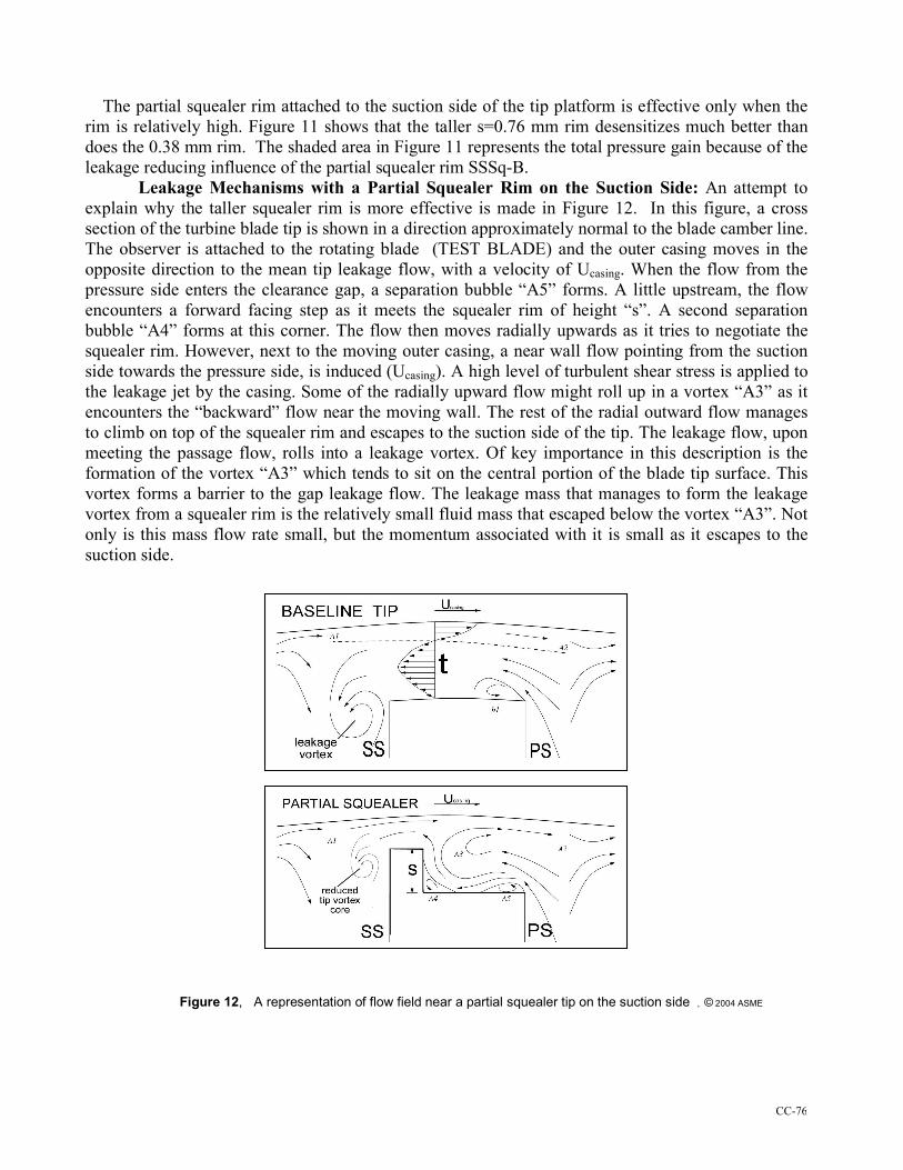
Leakage Mechanisms with a Partial Squealer Rim on the Suction Side: An attempt to explain why the taller squealer rim is more effective is made in Figure 12. In this figure, a cross section of the turbine blade tip is shown in a direction approximately normal to the blade camber line. The observer is attached to the rotating blade (TEST BLADE) and the outer casing moves in the opposite direction to the mean tip leakage flow, with a velocity of Ucasing. When the flow from the pressure side enters the clearance gap, a separation bubble “A5” forms. A little upstream, the flow encounters a forward facing step as it meets the squealer rim of height “s”. A second separation bubble “A4” forms at this corner. The flow then moves radially upwards as it tries to negotiate the squealer rim. However, next to the moving outer casing, a near wall flow pointing from the suction side towards the pressure side, is induced (Ucasing). A high level of turbulent shear stress is applied to the leakage jet by the casing. Some of the radially upward flow might roll up in a vortex “A3” as it encounters the “backward” flow near the moving wall. The rest of the radial outward flow manages to climb on top of the squealer rim and escapes to the suction side of the tip. The leakage flow, upon meeting the passage flow, rolls into a leakage vortex. Of key importance in this description is the formation of the vortex “A3” which tends to sit on the central portion of the blade tip surface. This vortex forms a barrier to the gap leakage flow. The leakage mass that manages to form the leakage vortex from a squealer rim is the relatively small fluid mass that escaped below the vortex “A3”. Not only is this mass flow rate small, but the momentum associated with it is small as it escapes to the suction side.
Figure 12, A representation of flow field near a partial squealer tip on the suction side , © 2004 ASME
CC-77
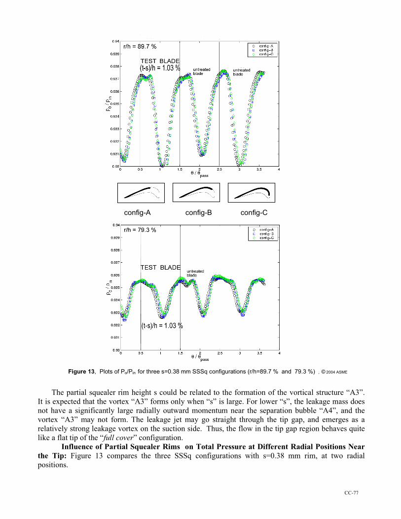
Figure 13, Plots of Po/Pin for three s=0.38 mm SSSq configurations (r/h=89.7 % and 79.3 %) , © 2004 ASME The partial squealer rim height s could be related to the formation of the vortical structure “A3”. It is expected that the vortex “A3” forms only when “s” is large. For lower “s”, the leakage mass does not have a significantly large radially outward momentum near the separation bubble “A4”, and the vortex “A3” may not form. The leakage jet may go straight through the tip gap, and emerges as a relatively strong leakage vortex on the suction side. Thus, the flow in the tip gap region behaves quite like a flat tip of the “full cover” configuration.
Influence of Partial Squealer Rims on Total Pressure at Different Radial Positions Near the Tip: Figure 13 compares the three SSSq configurations with s=0.38 mm rim, at two radial positions.
config-B config-A config-C
CC-78
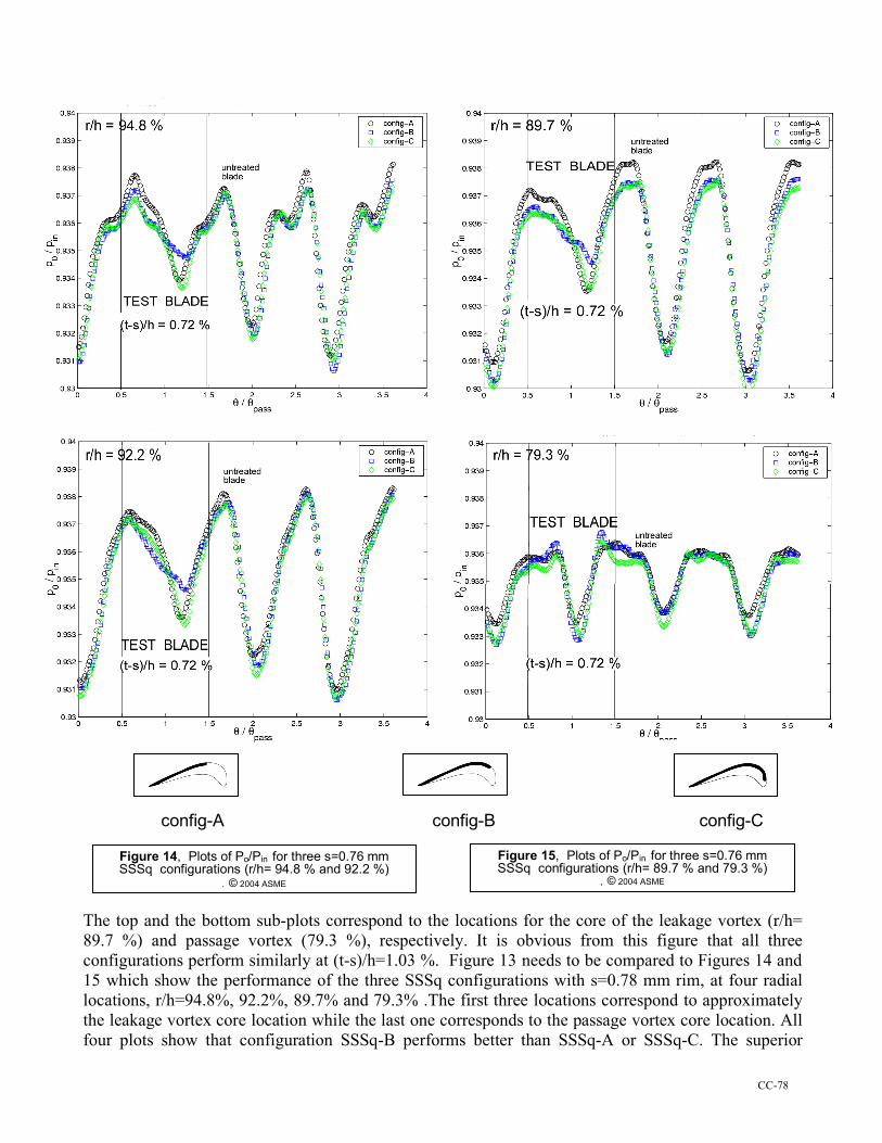
config-A config-B config-C The top and the bottom sub-plots correspond to the locations for the core of the leakage vortex (r/h= 89.7 %) and passage vortex (79.3 %), respectively. It is obvious from this figure that all three configurations perform similarly at (t-s)/h=1.03 %. Figure 13 needs to be compared to Figures 14 and 15 which show the performance of the three SSSq configurations with s=0.78 mm rim, at four radial locations, r/h=94.8%, 92.2%, 89.7% and 79.3% .The first three locations correspond to approximately the leakage vortex core location while the last one corresponds to the passage vortex core location. All four plots show that configuration SSSq-B performs better than SSSq-A or SSSq-C. The superior
Figure 14, Plots of Po/Pin for three s=0.76 mm SSSq configurations (r/h= 94.8 % and 92.2 %)
, © 2004 ASME
Figure 15, Plots of Po/Pin for three s=0.76 mm SSSq configurations (r/h= 89.7 % and 79.3 %)
, © 2004 ASME
CC-79
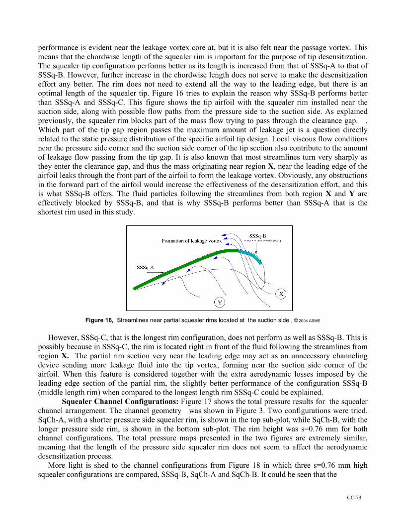
performance is evident near the leakage vortex core at, but it is also felt near the passage vortex. This means that the chordwise length of the squealer rim is important for the purpose of tip desensitization. The squealer tip configuration performs better as its length is increased from that of SSSq-A to that of SSSq-B. However, further increase in the chordwise length does not serve to make the desensitization effort any better. The rim does not need to extend all the way to the leading edge, but there is an optimal length of the squealer tip. Figure 16 tries to explain the reason why SSSq-B performs better than SSSq-A and SSSq-C. This figure shows the tip airfoil with the squealer rim installed near the suction side, along with possible flow paths from the pressure side to the suction side. As explained previously, the squealer rim blocks part of the mass flow trying to pass through the clearance gap. . Which part of the tip gap region passes the maximum amount of leakage jet is a question directly related to the static pressure distribution of the specific airfoil tip design. Local viscous flow conditions near the pressure side corner and the suction side corner of the tip section also contribute to the amount of leakage flow passing from the tip gap. It is also known that most streamlines turn very sharply as they enter the clearance gap, and thus the mass originating near region X, near the leading edge of the airfoil leaks through the front part of the airfoil to form the leakage vortex. Obviously, any obstructions in the forward part of the airfoil would increase the effectiveness of the desensitization effort, and this is what SSSq-B offers. The fluid particles following the streamlines from both region X and Y are effectively blocked by SSSq-B, and that is why SSSq-B performs better than SSSq-A that is the shortest rim used in this study.
Figure 16, Streamlines near partial squealer rims located at the suction side , © 2004 ASME However, SSSq-C, that is the longest rim configuration, does not perform as well as SSSq-B. This is possibly because in SSSq-C, the rim is located right in front of the fluid following the streamlines from region X. The partial rim section very near the leading edge may act as an unnecessary channeling device sending more leakage fluid into the tip vortex, forming near the suction side corner of the airfoil. When this feature is considered together with the extra aerodynamic losses imposed by the leading edge section of the partial rim, the slightly better performance of the configuration SSSq-B (middle length rim) when compared to the longest length rim SSSq-C could be explained.
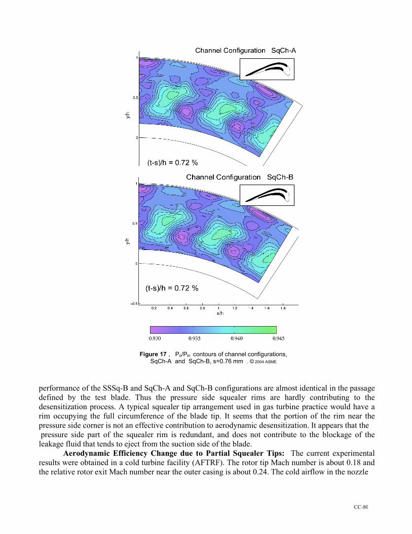
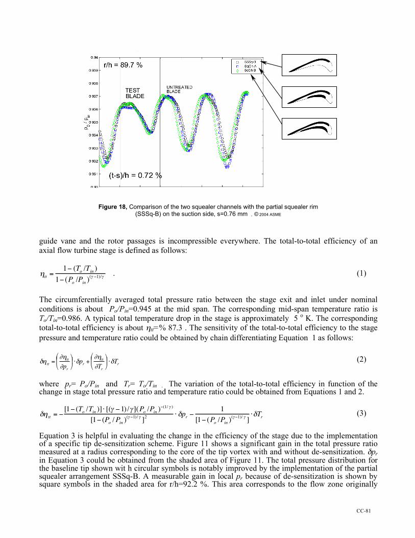
Squealer Channel Configurations: Figure 17 shows the total pressure results for the squealer channel arrangement. The channel geometry was shown in Figure 3. Two configurations were tried. SqCh-A, with a shorter pressure side squealer rim, is shown in the top sub-plot, while SqCh-B, with the longer pressure side rim, is shown in the bottom sub-plot. The rim height was s=0.76 mm for both channel configurations. The total pressure maps presented in the two figures are extremely similar, meaning that the length of the pressure side squealer rim does not seem to affect the aerodynamic desensitization process. More light is shed to the channel configurations from Figure 18 in which three s=0.76 mm high squealer configurations are compared, SSSq-B, SqCh-A and SqCh-B. It could be seen that the
CC-80
Figure 17 , Po/Pin contours of channel configurations, SqCh-A and SqCh-B, s=0.76 mm , © 2004 ASME
performance of the SSSq-B and SqCh-A and SqCh-B configurations are almost identical in the passage defined by the test blade. Thus the pressure side squealer rims are hardly contributing to the desensitization process. A typical squealer tip arrangement used in gas turbine practice would have a rim occupying the full circumference of the blade tip. It seems that the portion of the rim near the pressure side corner is not an effective contribution to aerodynamic desensitization. It appears that the pressure side part of the squealer rim is redundant, and does not contribute to the blockage of the leakage fluid that tends to eject from the suction side of the blade.
Aerodynamic Efficiency Change due to Partial Squealer Tips: The current experimental results were obtained in a cold turbine facility (AFTRF). The rotor tip Mach number is about 0.18 and the relative rotor exit Mach number near the outer casing is about 0.24. The cold airflow in the nozzle
CC-81
Figure 18, Comparison of the two squealer channels with the partial squealer rim (SSSq-B) on the suction side, s=0.76 mm , © 2004 ASME
guide vane and the rotor passages is incompressible everywhere. The total-to-total efficiency of an axial flow turbine stage is defined as follows:
!
"tt
=1# (T
o/T
in)
1# (Po/P
in)($ #1)/$
. (1)
The circumferentially averaged total pressure ratio between the stage exit and inlet under nominal conditions is about Po/Pin=0.945 at the mid span. The corresponding mid-span temperature ratio is To/Tin=0.986. A typical total temperature drop in the stage is approximately 5 o K. The corresponding total-to-total efficiency is about ηtt=% 87.3 . The sensitivity of the total-to-total efficiency to the stage pressure and temperature ratio could be obtained by chain differentiating Equation 1 as follows:
!
"# tt =$#tt$pr
%
& ' (
) * +"pr +
$#tt$Tr
%
& ' (
) * +"Tr (2)
where pr= Po/Pin and Tr= To/Tin . The variation of the total-to-total efficiency in function of the change in stage total pressure ratio and temperature ratio could be obtained from Equations 1 and 2.
!
"# tt = $[1$ (To /Tin )] % [(& $1)/&](Po /Pin )
$(1/ & )
[1$ (Po /Pin )(& $1)/ &
]2
% "pr $1
[1$ (Po /Pin )(&$1)/ &
]%"Tr (3)
Equation 3 is helpful in evaluating the change in the efficiency of the stage due to the implementation of a specific tip de-sensitization scheme. Figure 11 shows a significant gain in the total pressure ratio measured at a radius corresponding to the core of the tip vortex with and without de-sensitization. δpr in Equation 3 could be obtained from the shaded area of Figure 11. The total pressure distribution for the baseline tip shown wit h circular symbols is notably improved by the implementation of the partial squealer arrangement SSSq-B. A measurable gain in local pr because of de-sensitization is shown by square symbols in the shaded area for r/h=92.2 %. This area corresponds to the flow zone originally
CC-82
occupied by a tip vortex that had a significant amount of secondary kinetic energy and total pressure loss. The leakage reduction and the subsequent elimination of strong streamwise vorticity because of the squealer tip SSSq-B could be quantified from Equation 3. By assuming that “the local temperature change δTr due to squealer tip implementation is not significant in this cold turbine rig”, one could use the first term of Equation 3 for the calculation of efficiency improvement δηtt. The temperature change δTr is with respect to the case where no tip treatment is applied. The measurement of the time accurate total temperature at the exit of the turbine is not currently possible at a temporal resolution that is compatible with that of the current dynamic pressure measurements. Although the temperature change with respect to the baseline case (full cover/flat tip) is not available from the current experiments, it is expected that the turbine passage flow generates more work in this zone (r/h=92.2 %). This is because of the significant improvements in local total pressure distribution in the tip vortex dominated arera. Although small in magnitude in AFTRF, the second term in Equation 3 always adds to δηtt when δTr is negative which is the case for a successful aerodynamic de-sensitization attempt. If the maximum measured total pressure gain δpr (as shown in the shaded area of Figure 11) is used in Equation 3, a local maximum ηtt improvement of δηtt=+5.01 % is obtained for r/h=92.2 % . When ηtt improvements are area averaged in the shaded area, the overall de-sensitization improvement for the specific passage is about δηtt=+3.2 %. The current dynamic total pressure measurements at stage exit show that the favorable improvements in total-to-total efficiency are clearly observable from r/h=79 % to 94 % blade height. CONCLUSIONS The aerodynamic characteristics of partial squealer rims of varying lengths and heights were studied in a single stage cold turbine research facility. Two different channel arrangements were also examined. A 150 Khz dynamic pressure transducer in a total pressure probe arrangement can be used in the phase-averaged mapping of total pressure at the exit of a turbine stage. A complete high-resolution mapping of all blade passages at the rotor exit plane is an effective way of determining the aerodynamic impact of tip leakage vortices. In this approach, subsequent modifications made in the tip area can be visualized with respect to a baseline clearance in the rotor assembly. Experimental results indicate that partial squealer configurations seal the tip effectively. The chordwise length of a partial squealer rim near the suction side is an important parameter in defining the sealing effectiveness of the rim. The shortest rim (Config-A) and the longest rim (Config-C) were less effective than the mid-size (Config-B) in reducing the leakage flow. The suction side squealer is by itself capable of significant aerodynamic tip desensitization. The squealer rims extending from the trailing edge to about 6 % axial chord location near the leading edge perform best amongst suction side squealers of different chordwise lengths. Two different channel arrangements that have partial squealers both near the suction side corner and pressure side corner were investigated. “SqCh-A” with a shorter pressure side rim produced a desensitization performance very similar to “SqCh-B” with a longer rim on the pressure side. A comparison of the two channel arrangements with (Config-B) indicated that the sealing performance of the partial rim on the suction side is even better than the channel arrangements. The portion of the rim near the pressure side corner of the channel arrangement did not contribute to the sealing action. The influence of the tip vortex area total pressure ratio on the total-to-total efficiency of the turbine stage was evaluated for cold turbine flow conditions. If the maximum measured total pressure gain δpr is used, a “local maximum” ηtt improvement of δηtt=+5.01 % is obtained in the tip vortex dominated zone. When ηtt improvements are “area averaged” in the circumferential direction, the overall de-sensitization improvement is about δηtt=+3.2 % at r/h= 92.2 %.
CC-83
Although the current experiments demonstrate the aerodynamic gains obtained from partial squealer tips, a much detailed understanding of the leakage flow in the gap is needed. A numerical visualization effort in the tip gap area using a 3D, steady, viscous and turbulent flow system based on Reynolds-averaged Navier-Stokes equations is under progress with and without the relative motion of the outer casing. Acknowledgments:
Our research subcontract was sponsored by the U.S. Department of Energy “National Energy Technology Laboratory” NETL through a cooperative agreement with the South Carolina Institute for Energy Studies at Clemson University. The authors are thankful to Drs.Wenglarz and Golan at SCIES/HEET for their support. The authors are also indebted to late Prof. Lakshminarayana for his continuous criticism and suggestions over the years the AFTRF was developed into a fully operational turbine research facility. Nomenclature c Rotor axial chord length at tip = 0.129 m Cp Pressure coefficient
!
(p " pl) /(0.5#Um
2)
(t-s)/h Effective clearance height between squealer rim top plane and outer casing h Rotor blade height = 0.123 m p,patm Static pressure, atmospheric pressure Po/Pin Total pressure (stage exit to inlet) ratio
!
pl Passage averaged local mean pressure at the rotor inlet r/h Non-dimensional radial position measured from hub surface (also y/h in contour plots) r,θ,z Radial, tangential and axial coordinates s Height of the squealer rim measured from the base of the untreated tip section, (see Figures 2 , 3 and 12) SSSq-A The shortest partial squealer tip on the suction side SSSq-B The most optimal partial squealer tip on the suction side (mid-sized) SSSq-C The longest partial squealer tip on the suction side SqCh-A Channel type squealer tip-A (or B), (see Figure 3) t Rotor tip clearance height without a squealer rim To/Tin Total temperature (stage exit to inlet) ratio Um Mean wheel speed at rotor mid-span Vsec Secondary velocity (Vdesign-Vmeasured) x,y,z Coordinates, (x is also axial direction)
References [1] Heyes, F.J.G. and Hodson, H.P., 1993, “Measurement and Prediction of Tip Clearance Flow In Linear Turbine Cascades,” ASME Journal of Turbomachinery” , Vol.115, pp.376-382. [2] Sjolander, S.A. and Cao, D., 1994, “Measurements of the Flow in an Idealized Turbine Gap,” ASME paper 94 -GT-74. [3] Morphis, G. and Bindon, J.P., 1988, “The Effects of Relative Motion, Blade Edge Radius and Gap Size on the Blade Tip Distribution in an Annular Turbine Cascade with Tip Clearance,” ASME paper 88-GT-256. [4] Azad, Gm. S., Han, J.C., Teng, S., Boyle, R.J, 2000, “Heat Transfer and Pressure Distributions on a Gas Turbine Blade Tip,” ASME paper 2000-GT-194. [5] Dey, D. and Camci, C., 2001 “Aerodynamic Tip De-sensitization of an Axial Turbine Rotor Using Tip Platform Extensions,” ASME paper 2001-GT-484. [6] Anderson, R.H., 1979, “Tip Cooling for Turbine Blades,” U.S.Patent # 4,142,824, March 6, 1979. [7] Azad, Gm. S., Han, J.C., Boyle, R.J., 2000, “Heat Transfer and Flow on the Squealer Tip of a Gas Turbine Blade,” ASME paper 2000-GT-195.
CC-84
[8] Heyes, F.J.G. and Hodson, H.P., Dailey, G.M, 1992, “The Effect of Blade Tip Geometry on the Tip Leakage Flow in Axial Turbine Cascades,” ASME Journal of Turbomachinery, Vol.114, pp.643-651. [9] Bunker, R.S. and Bailey, J.C., 2000, “ Blade Tip Heat Transfer and Flow with Chordwise Sealing Strips,” International Symposium on Transport Phenomena and Dynamics of Rotating Machinery (ISROMAC), Honolulu, Hawaii, pp.548-555. [10] Ameri, A.A., 2001, “Heat Transfer and Flow on the Blade Tip of a Gas Turbine Equipped with a Mean Camber-line Strip,” ASME Journal of Turbomachinery, Vol.123, pp.704-708. [11] Ameri, A.A., Steinthorsson, E., Rigby, L.D., “Effects of Squealer Tip on Rotor Heat Transfer and Efficiency,” ASME paper 1997-GT-128. [12] Azad, Gm. S., Han, J.C., Bunker, R.S.,Lee,C.P., 2001, “Effect of Squealer Geometry Arrangement on Gas Turbine Blade Tip Heat Transfer,” ASME/IMECE 2001/HTD-24314, HTD-Vol.369-5, pp. 297-305. [13] Lakshminarayana, B., Camci, C., Halliwell, I., and Zaccaria, M., 1992, “Investigation of Three Dimensional Flow Field in a Turbine Including Rotor/Stator Interaction. Part I: Design Development and Performance of the Research Facility,” AIAA paper 92-3326, presented at the ASME-AIAA Joint Prop. Conf., Nashville, Tennessee. [14] Dey, D.. 2001, “Aerodynamic Tip Desensitization in Axial Flow Turbines,” Ph.D. Thesis, 2001d, The Pennsylvania State University. [15] Zaccaria, M. and Lakshminarayana, B., 1995, “Investigation of Three Dimensional Flow Field at the Exit of a Turbine Nozzle,” AIAA Journal of Propulsion and Power, Vol.11, No.1, pp.55-63. [16] Ristic, D., Lakshminarayana, B., Chu, S., 1998, “Three-dimensional Flow Field Downstream of an Axial Flow Turbine Rotor,” AIAA paper 98-3572, presented at the 34th AIAA/ASME/SAE/ASEE Joint Propulsion Conference and Exhibit, Cleveland, Ohio. [17] Yamamoto, A., 1989, “Endwall Flow/loss mechanisms in a Linear Turbine Cascade with Blade Tip Clearance,” ASME Journal of Turbomachinery, Vol.111, pp.264-275. [18] Xiao, X., McCarter, A.A., Lakshminarayana, B., 2000, “Tip Clearance Effects in a Turbine Rotor, Part I: Pressure Field and Loss,” ASME paper 2000-GT-476. [19] Bindon, J.P., 1987, “Pressure Distribution in the Tip Clearance Region of an Unshrouded Axial Turbine, as Affecting the Problem of Tip Burnout,” ASME paper 87-GT-230. [20] Sjolander, S.A., 1997, “Overview of Tip Clearance Effects in Axial Turbines,” VKI Lect. Series, “Sec. and Tip Cl. Flows in Axial Turbines, dir. by C.Sieverding, C.H., the Von Karman Institute for Fluid Dynamics, Belgium. [21] Luo, J., Lakshminarayana, B., 1997, “3D Navier-Stokes Analysis of Turbine Rotor and Tip Leakage Flow-field,” ASME paper 97-GT-421.