TIP-450 Operator’s Manual - Fluke...
59
TIP-450 Operator’s Manual Wallboard Temperature Imaging and Profiling System www.raytek.com for up-to-the-minute features Rev B 1/03 57900-1
Transcript of TIP-450 Operator’s Manual - Fluke...

TIP-450 Operator’s Manual
Wallboard Temperature Imaging and Profiling System
www.raytek.comfor up-to-the-minute features
Rev B1/03
57900-1

Internet Address: www.raytek.com
Raytek and Thermalert are registered trademarks and MP40 and MP50 are trademarks of Raytek Corp. All other
brands or products are trademarks of their respective owners.
© 2002 Raytek Corporation
Worldwide HeadquartersRaytek Corporation1201 Shaffer Rd. PO Box 1820Santa Cruz, CA 95061-1820 USATel: 1 800 227 80741 831 458 1110Fax: 1 831 458 [email protected]
Raytek de Mexico, S.A. de C.V.13 Poniente #2313-2 Col. La Piedad Puebla, Pue. CP 72160 MexicoTel: 52-222 230 4380Fax: 52-222 230 [email protected]
Raytek China Company Yeqing Plaza, No.9 Wangjing Beilu Chaoyang DistrictBeijing, China 100102Tel: (8610) 64392255Fax: (8610) [email protected]
Raytek Japan, Inc. Okajima Building 1-2-14 Nishihonmachi, Nishi-kuOsaka 550-0005, JapanTel: 81 6 4390 5015Fax: 81 6 4390 [email protected]
South American HeadquartersRaytek do BrasilRua Francisco Prestes Maia, 75Sorocaba, SP BrasilCEP 18040-650Tel: 55 15 233 6338Fax: 55 15 233 [email protected]
European HeadquartersRaytek GmbHBlankenburger Staße 135D-13127 Berlin, GermanyTel: 49 30 4 78 00 84 00 Fax: 49 30 4 71 02 [email protected]
Raytek United KingdomPO Box 120 Milton KeynesBuckinghamshire MK1 1ZUUnited KingdomTel: 44 1908 630800Fax: 44 1908 [email protected]
Raytek France5 Avenue du 1 MaiZae de Glaises91120 Palaiseau, FranceTel: 33 1 64 53 1540Fax: 33 1 64 53 [email protected]

WARRANTYRaytek warrants this instrument to be free from defects in material and workmanship under nor-mal use and service for the period of one year from date of purchase. This warranty extends onlyto the original purchaser. This warranty shall not apply to fuses, batteries, or any product whichhas been subject to misuse, neglect, accident, or abnormal conditions of operation.
In the event of failure of a product covered by this warranty, Raytek will repair the instrumentwhen it is returned to an authorized Service Facility within one year of the original purchase, pro-vided the warrantor’s examination discloses to its satisfaction that the product was defective. Thewarrantor may, at its option, replace the product in lieu of repair. With regard to any instrumentreturned within one year of the original purchase, said repairs or replacement will be made with-out charge. If the failure has been caused by misuse, neglect, accident, or abnormal conditions ofoperation, repairs will be billed at nominal cost. In such cases, an estimate will be submitted beforework is started, if requested.
THE FOREGOING WARRANTY IS IN LIEU OF ALL OTHER WARRANTIES, EXPRESSEDOR IMPLIED, INCLUDING BUT NOT LIMITED TO ANY IMPLIED WARRANTY OF MER-CHANTIBILITY, FITNESS, OR ADEQUACY FOR ANY PARTICULAR PURPOSE OR USE.RAYTEK SHALL NOT BE LIABLE FOR ANY SPECIAL, INCIDENTAL OR CONSEQUEN-TIAL DAMAGES, WHETHER IN CONTRACT, TORT, OR OTHERWISE.
SOFTWARE WARRANTYRaytek warrants that the program disk is free from defects in material and workmanship, assum-ing normal use, for a period of one year. Except for this warranty, Raytek makes no warranty orrepresentation, either expressed or implied, with respect to this software or documentation,including its quality, performance, merchantability, or fitness for a particular purpose. As a result,this software and documentation are licensed “as is,” and the licensee (i.e., the User) assumes theentire risk as to its quality and performance.
The liability of Raytek under this warranty shall be limited to the amount paid by the User. In noevent shall Raytek be liable for any costs including but not limited to those incurred as a result oflost profits or revenue, loss of use of the computer software, loss of data, the cost of substitute soft-ware, claims by third parties, or for other similar costs.
Raytek software and documentation are copyrighted with all rights reserved. It is illegal to makecopies for another person.


Introduction Software Installation
Operation System Access Buttons . . . . . . . . . . . . . . . . . . . . . . . . . . . . . . . . . . . . . . . . . . . . . . . .1
Scanner Initialization . . . . . . . . . . . . . . . . . . . . . . . . . . . . . . . . . . . . . . . . . . . . . . . . . . .2
Real Time Board Thermal Map . . . . . . . . . . . . . . . . . . . . . . . . . . . . . . . . . . . . . . . . . . .2Deck . . . . . . . . . . . . . . . . . . . . . . . . . . . . . . . . . . . . . . . . . . . . . . . . . . . . . . . . . . . . . . . . . . . .2Lines Scanned . . . . . . . . . . . . . . . . . . . . . . . . . . . . . . . . . . . . . . . . . . . . . . . . . . . . . . . . . . . . . .2Background Temp. . . . . . . . . . . . . . . . . . . . . . . . . . . . . . . . . . . . . . . . . . . . . . . . . . . . . . . . . . .2Process Temp . . . . . . . . . . . . . . . . . . . . . . . . . . . . . . . . . . . . . . . . . . . . . . . . . . . . . . . . . . . . . .2Deck Temp . . . . . . . . . . . . . . . . . . . . . . . . . . . . . . . . . . . . . . . . . . . . . . . . . . . . . . . . . . . . . . . .2Press to Hold . . . . . . . . . . . . . . . . . . . . . . . . . . . . . . . . . . . . . . . . . . . . . . . . . . . . . . . . . . . . . . .2
Dry End Profile - Real Time . . . . . . . . . . . . . . . . . . . . . . . . . . . . . . . . . . . . . . . . . . . . . . .3Historical . . . . . . . . . . . . . . . . . . . . . . . . . . . . . . . . . . . . . . . . . . . . . . . . . . . . . . . . . . . . . . . . . .3Process Temp . . . . . . . . . . . . . . . . . . . . . . . . . . . . . . . . . . . . . . . . . . . . . . . . . . . . . . . . . . . . . .3Board Sample . . . . . . . . . . . . . . . . . . . . . . . . . . . . . . . . . . . . . . . . . . . . . . . . . . . . . . . . . . . . . .3
Dry End Profile - Historical . . . . . . . . . . . . . . . . . . . . . . . . . . . . . . . . . . . . . . . . . . . . . . .3Go to Real Time . . . . . . . . . . . . . . . . . . . . . . . . . . . . . . . . . . . . . . . . . . . . . . . . . . . . . . . . . . . . .3Historical . . . . . . . . . . . . . . . . . . . . . . . . . . . . . . . . . . . . . . . . . . . . . . . . . . . . . . . . . . . . . . . . . .3
Trend Chart - Real Time . . . . . . . . . . . . . . . . . . . . . . . . . . . . . . . . . . . . . . . . . . . . . . . . .4Chart Span Time . . . . . . . . . . . . . . . . . . . . . . . . . . . . . . . . . . . . . . . . . . . . . . . . . . . . . . . . . . . .4
Historical Trend Chart . . . . . . . . . . . . . . . . . . . . . . . . . . . . . . . . . . . . . . . . . . . . . . . . . . .4Chart Span Time . . . . . . . . . . . . . . . . . . . . . . . . . . . . . . . . . . . . . . . . . . . . . . . . . . . . . . . . . . . .4Chart Shift . . . . . . . . . . . . . . . . . . . . . . . . . . . . . . . . . . . . . . . . . . . . . . . . . . . . . . . . . . . . . . . . .4Reset to Real Time . . . . . . . . . . . . . . . . . . . . . . . . . . . . . . . . . . . . . . . . . . . . . . . . . . . . . . . . . . .4
Maintenance Operator Level About TIP450 . . . . . . . . . . . . . . . . . . . . . . . . . . . . . . . . . . . . . . . . . . . . . . . . . . . . . . . . .5
Graphics/Trend Charts . . . . . . . . . . . . . . . . . . . . . . . . . . . . . . . . . . . . . . . . . . . . . . . . . .5Setpoint Display . . . . . . . . . . . . . . . . . . . . . . . . . . . . . . . . . . . . . . . . . . . . . . . . . . . . . . . . . . . .5
Scanner Comms Reset . . . . . . . . . . . . . . . . . . . . . . . . . . . . . . . . . . . . . . . . . . . . . . . . .6
Reset Scanner Trigger . . . . . . . . . . . . . . . . . . . . . . . . . . . . . . . . . . . . . . . . . . . . . . . . . .7Scans Required . . . . . . . . . . . . . . . . . . . . . . . . . . . . . . . . . . . . . . . . . . . . . . . . . . . . . . . . . . . .7Scans Completed . . . . . . . . . . . . . . . . . . . . . . . . . . . . . . . . . . . . . . . . . . . . . . . . . . . . . . . . . . .7Background Average Temperature and Background Maximum Temperature . . . . . . . . . . . . . . .7Trigger Temp . . . . . . . . . . . . . . . . . . . . . . . . . . . . . . . . . . . . . . . . . . . . . . . . . . . . . . . . . . . . . . .7
Software Configuration and System Setup Maintenance system Access . . . . . . . . . . . . . . . . . . . . . . . . . . . . . . . . . . . . . . . . . . . . .9
Operator . . . . . . . . . . . . . . . . . . . . . . . . . . . . . . . . . . . . . . . . . . . . . . . . . . . . . . . . . . . . .9
Supervisor . . . . . . . . . . . . . . . . . . . . . . . . . . . . . . . . . . . . . . . . . . . . . . . . . . . . . . . . . . .9
Administrator . . . . . . . . . . . . . . . . . . . . . . . . . . . . . . . . . . . . . . . . . . . . . . . . . . . . . . . . .9
TIP-450 Operator’s Manual Table of Contents
Contents

Table of Contents TIP-450 Operator’s Manual
Maintenance Administrator Level General Configuration . . . . . . . . . . . . . . . . . . . . . . . . . . . . . . . . . . . . . . . . . . . . . . . . . .10
Temp Units . . . . . . . . . . . . . . . . . . . . . . . . . . . . . . . . . . . . . . . . . . . . . . . . . . . . . . . . . . . . . . .10Length Units . . . . . . . . . . . . . . . . . . . . . . . . . . . . . . . . . . . . . . . . . . . . . . . . . . . . . . . . . . . . . . .10Time Display . . . . . . . . . . . . . . . . . . . . . . . . . . . . . . . . . . . . . . . . . . . . . . . . . . . . . . . . . . . . . . .10Printer Available . . . . . . . . . . . . . . . . . . . . . . . . . . . . . . . . . . . . . . . . . . . . . . . . . . . . . . . . . . . .10Deck Numbering . . . . . . . . . . . . . . . . . . . . . . . . . . . . . . . . . . . . . . . . . . . . . . . . . . . . . . . . . . .10Max. Board Length . . . . . . . . . . . . . . . . . . . . . . . . . . . . . . . . . . . . . . . . . . . . . . . . . . . . . . . . .10Outfeed . . . . . . . . . . . . . . . . . . . . . . . . . . . . . . . . . . . . . . . . . . . . . . . . . . . . . . . . . . . . . . . . . .10Board Arrival Tracking . . . . . . . . . . . . . . . . . . . . . . . . . . . . . . . . . . . . . . . . . . . . . . . . . . . . . . .10
Scanner Configuraton . . . . . . . . . . . . . . . . . . . . . . . . . . . . . . . . . . . . . . . . . . . . . . . . . .11Scanner Temperature Range . . . . . . . . . . . . . . . . . . . . . . . . . . . . . . . . . . . . . . . . . . . . . . . . . .11Baud Rate . . . . . . . . . . . . . . . . . . . . . . . . . . . . . . . . . . . . . . . . . . . . . . . . . . . . . . . . . . . . . . . .11Data Points/Scan . . . . . . . . . . . . . . . . . . . . . . . . . . . . . . . . . . . . . . . . . . . . . . . . . . . . . . . . . . .11Field of View . . . . . . . . . . . . . . . . . . . . . . . . . . . . . . . . . . . . . . . . . . . . . . . . . . . . . . . . . . . . . . .11Trigger Temperature Delta . . . . . . . . . . . . . . . . . . . . . . . . . . . . . . . . . . . . . . . . . . . . . . . . . . . .11Drop-out Temperature Delta . . . . . . . . . . . . . . . . . . . . . . . . . . . . . . . . . . . . . . . . . . . . . . . . . . .12MP Scan Rate . . . . . . . . . . . . . . . . . . . . . . . . . . . . . . . . . . . . . . . . . . . . . . . . . . . . . . . . . . . . .12Scanner Shut-Down . . . . . . . . . . . . . . . . . . . . . . . . . . . . . . . . . . . . . . . . . . . . . . . . . . . . . . . . .12Rearm Status . . . . . . . . . . . . . . . . . . . . . . . . . . . . . . . . . . . . . . . . . . . . . . . . . . . . . . . . . . . . . .12Scanner Data . . . . . . . . . . . . . . . . . . . . . . . . . . . . . . . . . . . . . . . . . . . . . . . . . . . . . . . . . . . . . .12
Scanner Comms Reset . . . . . . . . . . . . . . . . . . . . . . . . . . . . . . . . . . . . . . . . . . . . . . . . .13
Graphics/Trend Charts . . . . . . . . . . . . . . . . . . . . . . . . . . . . . . . . . . . . . . . . . . . . . . . . .14 Setpoint Display . . . . . . . . . . . . . . . . . . . . . . . . . . . . . . . . . . . . . . . . . . . . . . . . . . . . . . . . . . . .14Temperature Setpoint . . . . . . . . . . . . . . . . . . . . . . . . . . . . . . . . . . . . . . . . . . . . . . . . . . . . . . . .14Temperature Band . . . . . . . . . . . . . . . . . . . . . . . . . . . . . . . . . . . . . . . . . . . . . . . . . . . . . . . . . .14Trend Chart Configuration . . . . . . . . . . . . . . . . . . . . . . . . . . . . . . . . . . . . . . . . . . . . . . . . . . . .14Trend Chart Minimum Temperature . . . . . . . . . . . . . . . . . . . . . . . . . . . . . . . . . . . . . . . . . . . . .14Number or Major Divisions . . . . . . . . . . . . . . . . . . . . . . . . . . . . . . . . . . . . . . . . . . . . . . . . . . . .14Map Display . . . . . . . . . . . . . . . . . . . . . . . . . . . . . . . . . . . . . . . . . . . . . . . . . . . . . . . . . . . . . . .15Map Display Maximum Temperature . . . . . . . . . . . . . . . . . . . . . . . . . . . . . . . . . . . . . . . . . . . .15Map Display Minimum Temperature . . . . . . . . . . . . . . . . . . . . . . . . . . . . . . . . . . . . . . . . . . . . .15Map Temperature Span . . . . . . . . . . . . . . . . . . . . . . . . . . . . . . . . . . . . . . . . . . . . . . . . . . . . . .15End Profile Configuration . . . . . . . . . . . . . . . . . . . . . . . . . . . . . . . . . . . . . . . . . . . . . . . . . . . . .15End Profile Maximum Temperature . . . . . . . . . . . . . . . . . . . . . . . . . . . . . . . . . . . . . . . . . . . . . .15End Profile Minimum Temperature . . . . . . . . . . . . . . . . . . . . . . . . . . . . . . . . . . . . . . . . . . . . . .15End Profile Temperature Span . . . . . . . . . . . . . . . . . . . . . . . . . . . . . . . . . . . . . . . . . . . . . . . . .15Board/Deck Average . . . . . . . . . . . . . . . . . . . . . . . . . . . . . . . . . . . . . . . . . . . . . . . . . . . . . . . .15Show/Hide Average . . . . . . . . . . . . . . . . . . . . . . . . . . . . . . . . . . . . . . . . . . . . . . . . . . . . . . . . .15Temperature Location . . . . . . . . . . . . . . . . . . . . . . . . . . . . . . . . . . . . . . . . . . . . . . . . . . . . . . .16Scanner Location . . . . . . . . . . . . . . . . . . . . . . . . . . . . . . . . . . . . . . . . . . . . . . . . . . . . . . . . . . .16Dryer Discharge . . . . . . . . . . . . . . . . . . . . . . . . . . . . . . . . . . . . . . . . . . . . . . . . . . . . . . . . . . . .16Drive Chain Location . . . . . . . . . . . . . . . . . . . . . . . . . . . . . . . . . . . . . . . . . . . . . . . . . . . . . . . .16Board Flow Direction . . . . . . . . . . . . . . . . . . . . . . . . . . . . . . . . . . . . . . . . . . . . . . . . . . . . . . . .16
Change Access Codes . . . . . . . . . . . . . . . . . . . . . . . . . . . . . . . . . . . . . . . . . . . . . . . . .18
Filter Change . . . . . . . . . . . . . . . . . . . . . . . . . . . . . . . . . . . . . . . . . . . . . . . . . . . . . . . .19Filter Change Status . . . . . . . . . . . . . . . . . . . . . . . . . . . . . . . . . . . . . . . . . . . . . . . . . . . . . . . . .19Filter Interval Set . . . . . . . . . . . . . . . . . . . . . . . . . . . . . . . . . . . . . . . . . . . . . . . . . . . . . . . . . . . .19

TIP-450 Operator’s Manual Table of Contents
Fixed IR Sensor Setup Introduction . . . . . . . . . . . . . . . . . . . . . . . . . . . . . . . . . . . . . . . . . . . . . . . . . . . . . . . . .20
Installation Warning . . . . . . . . . . . . . . . . . . . . . . . . . . . . . . . . . . . . . . . . . . . . . . . . . . . .20
Fixed IR Configure and Test . . . . . . . . . . . . . . . . . . . . . . . . . . . . . . . . . . . . . . . . . . . . .21Fixed Hits . . . . . . . . . . . . . . . . . . . . . . . . . . . . . . . . . . . . . . . . . . . . . . . . . . . . . . . . . . . . . . . . .21Fixed Yint . . . . . . . . . . . . . . . . . . . . . . . . . . . . . . . . . . . . . . . . . . . . . . . . . . . . . . . . . . . . . . . . .21Fixed Slope . . . . . . . . . . . . . . . . . . . . . . . . . . . . . . . . . . . . . . . . . . . . . . . . . . . . . . . . . . . . . . .21Scanner Yint . . . . . . . . . . . . . . . . . . . . . . . . . . . . . . . . . . . . . . . . . . . . . . . . . . . . . . . . . . . . . . .21Scanner Slope . . . . . . . . . . . . . . . . . . . . . . . . . . . . . . . . . . . . . . . . . . . . . . . . . . . . . . . . . . . . .21
Sensor Configuration . . . . . . . . . . . . . . . . . . . . . . . . . . . . . . . . . . . . . . . . . . . . . . . . . .22Measured Temperature . . . . . . . . . . . . . . . . . . . . . . . . . . . . . . . . . . . . . . . . . . . . . . . . . . . . . .22Trigger Status . . . . . . . . . . . . . . . . . . . . . . . . . . . . . . . . . . . . . . . . . . . . . . . . . . . . . . . . . . . . . .22Trigger Temperature Setpoint . . . . . . . . . . . . . . . . . . . . . . . . . . . . . . . . . . . . . . . . . . . . . . . . . .22Fixed Sensor Deck # . . . . . . . . . . . . . . . . . . . . . . . . . . . . . . . . . . . . . . . . . . . . . . . . . . . . . . . .22Align Fixed Sensor . . . . . . . . . . . . . . . . . . . . . . . . . . . . . . . . . . . . . . . . . . . . . . . . . . . . . . . . . .22
Analog Inputs . . . . . . . . . . . . . . . . . . . . . . . . . . . . . . . . . . . . . . . . . . . . . . . . . . . . . . . .24Channel . . . . . . . . . . . . . . . . . . . . . . . . . . . . . . . . . . . . . . . . . . . . . . . . . . . . . . . . . . . . . . . . . .24Zero Offset (ma) . . . . . . . . . . . . . . . . . . . . . . . . . . . . . . . . . . . . . . . . . . . . . . . . . . . . . . . . . . . .24Span (Engineering Units) . . . . . . . . . . . . . . . . . . . . . . . . . . . . . . . . . . . . . . . . . . . . . . . . . . . . .24Damping Seconds . . . . . . . . . . . . . . . . . . . . . . . . . . . . . . . . . . . . . . . . . . . . . . . . . . . . . . . . . .24Raw Data (ma) . . . . . . . . . . . . . . . . . . . . . . . . . . . . . . . . . . . . . . . . . . . . . . . . . . . . . . . . . . . . .24PV (Engrg. Units) . . . . . . . . . . . . . . . . . . . . . . . . . . . . . . . . . . . . . . . . . . . . . . . . . . . . . . . . . . .24Multiplier . . . . . . . . . . . . . . . . . . . . . . . . . . . . . . . . . . . . . . . . . . . . . . . . . . . . . . . . . . . . . . . . . .24Analog Inputs . . . . . . . . . . . . . . . . . . . . . . . . . . . . . . . . . . . . . . . . . . . . . . . . . . . . . . . . . . . . . .24
Digital I/O . . . . . . . . . . . . . . . . . . . . . . . . . . . . . . . . . . . . . . . . . . . . . . . . . . . . . . . . . . .25
Routine Maintenance Filter Changes . . . . . . . . . . . . . . . . . . . . . . . . . . . . . . . . . . . . . . . . . . . . . . . . . . . . . . . .26
Scanner Window . . . . . . . . . . . . . . . . . . . . . . . . . . . . . . . . . . . . . . . . . . . . . . . . . . . . .26Appendix A: CBCOMM Communications Utility
About the CBCOM Utility . . . . . . . . . . . . . . . . . . . . . . . . . . . . . . . . . . . . . . . . . . . . . . .27
Running CBCOM . . . . . . . . . . . . . . . . . . . . . . . . . . . . . . . . . . . . . . . . . . . . . . . . . . . . .27
General Notes for Module Configuration . . . . . . . . . . . . . . . . . . . . . . . . . . . . . . . . . . . .28
Module Details - RIO-01 (7041 - 14*D) . . . . . . . . . . . . . . . . . . . . . . . . . . . . . . . . . . . . .29
Module Details - RIO-02 (7050 / 8*DO) . . . . . . . . . . . . . . . . . . . . . . . . . . . . . . . . . . . . .30
Module Details - RIO-03 (7017 - 8*AI . . . . . . . . . . . . . . . . . . . . . . . . . . . . . . . . . . . . . .31Appendix B: Special Configuration of Windows NT 4.0
User Configuration . . . . . . . . . . . . . . . . . . . . . . . . . . . . . . . . . . . . . . . . . . . . . . . . . . . .33
Notes regarding the AutoLogon feature . . . . . . . . . . . . . . . . . . . . . . . . . . . . . . . . . . . .33Appendix C: Program and Data Files & General Information
The Operating Program . . . . . . . . . . . . . . . . . . . . . . . . . . . . . . . . . . . . . . . . . . . . . . . .35
Configuration Data Files . . . . . . . . . . . . . . . . . . . . . . . . . . . . . . . . . . . . . . . . . . . . . . . .35
Operation and Maintenance Manuals . . . . . . . . . . . . . . . . . . . . . . . . . . . . . . . . . . . . . .35Appendix D: Startup QuickStart Guide
QuickStart Procedues . . . . . . . . . . . . . . . . . . . . . . . . . . . . . . . . . . . . . . . . . . . . . . . . . .37
QuickStart Reference Drawings . . . . . . . . . . . . . . . . . . . . . . . . . . . . . . . . . . . . . . . . . .40

Table of Contents TIP-450 Operator’s Manual

TIP-450 Operator’s Manual Introduction
The TIP-450 system is a linescanner and software solution for drying uniformity of gypsum wallboard, created for
convenient, reliable monitoring, control and analysis of temperature data.
The TIP-450 package includes the following:
• Air purge Assembly
• Thermalert® MP50™ Thermal Imager
• PC and touch-screen monitor
• Data acquisition hardware
• Rittal NEMA-12 enclosures
• CD-ROM
• Drop Gate Relay Assembly
• Fixed IR sensor and target assemblies
• Schematic and installation drawings
• Operator’s and Maintenance Manual
A Raytek Application Specialist will set up your TIP-450 Wallboard Temperature Imaging and Profile System. All
software and configurations will be completed for you and the Raytek Application Specialist will create a CD for you
with your particular system setup. If you need to reinstall the software program due to a computer failure or install it
on a new computer, use the following directions as a guide. Please note that the computer must be running at least
Windows NT 4.0 (Service Pack 4). This program is not compatible with Windows 95 or 98.
ImportantExit all Windows applications, and disable any virus programs and screen savers, beforeinstalling the TIP-450 software.
View the README.TXT file, if included on your CD, for last minute system compatibilityand troubleshooting information.
Complete the following steps to install your TIP-450 software:
1. Insert the TIP-450 Software CD created by the Raytek Application Specialist into the CD-ROM drive.
2. Create a new directory. Name it TIP-450.
3. Copy the contents of the CD to the TIP-450 directory.
Introduction
Software Installation

Introduction TIP-450 Operator’s Manual

TIP-450 Operator’s Manual 1
The TIP-450 software program follows standard Windows conventions. The following sections were written with the
assumption that you are familiar with the Windows NT/2000 operating environment. If you need help using
Windows, refer to the manual that came with your Windows software. When you turn on the computer, the TIP-450
software program automatically starts.
The following sections describe and explain the use of the screens, menus, and buttons.
System Access ButtonsAccess all functions through common buttons located at the top of the screen (see example below).
• Board Map displays the real-time thermal image for each board set.
• Dry End Profile displays the dryer discharge average temperatures across each deck.
• Trend Chart displays the real time and historical trend charts.
• Maint. displays the maintenance access menu.
Operation
Access Buttons when printing is not allowed.
Access Buttons when printing is allowed.
Access Buttons to confirm printing operation. Once printing is selected you must select either thePrint Yes or Print No button.

2 TIP-450 Operator’s Manual
Scanner InitializationThe MP50 linescanner is initialized when the TIP-450 program loads or when Scanner Comms Reset is selected
from the Maintenance screen.
The screen at right shows the status of the scanner
commands and the responses. A response of
OK to most commands indicates successful
configuration and communications. The Scanner
I.D. and Software (S.W.) Rev. fields return the
scanner hardware ID number and current version
of the scanner firmware. And the Deck Input,
Misc. Input, and Analog Input Modules return
the values.
Note: A failure in the RIO system will result inblank responses.
Real Time Board Thermal MapThe real time screen displays the board sets as they exit the dryer. As the data from a new board set is received, it over-
writes the display from the previous set.
Deck - Indicates the deck from which the currently displayed board arrived.
Lines Scanned - Indicates the total number ofscanner passes for the current board set.
Back Ground Temp - The ambient temperature below the scanning area is the back-ground temperature. The scanner uses the temper-ature difference of the background and the passingwallboard to sense when a Board Map should bedisplayed, see page 7 for more information.
Process Temp - Displays the average tempera-
ture of all board sets coming from the dryer.
Deck Temp - Displays the average temperature of allboards coming from an individual deck.
Press to Hold - To pause the display, press the Press to Hold button, then to continue scanning press the buttonagain.
Reference Color/Temperature Bar
5 122 72.8 155.8
147
153
158
151
154
150
162
161
155
167
TIP-450 Operator’s Manual 3
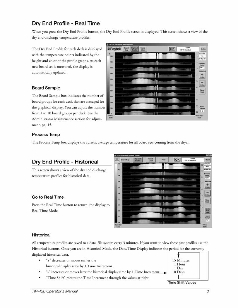
Dry End Profile - Real TimeWhen you press the Dry End Profile button, the Dry End Profile screen is displayed. This screen shows a view of the
dry end discharge temperature profiles.
The Dry End Profile for each deck is displayed
with the temperature points indicated by the
height and color of the profile graphs. As each
new board set is measured, the display is
automatically updated.
Board Sample
The Board Sample box indicates the number of
board groups for each deck that are averaged for
the graphical display. You can adjust the number
from 1 to 10 board groups per deck. See the
Administrator Maintenance section for adjust-
ment, pg. 15.
Process Temp
The Process Temp box displays the current average temperature for all board sets coming from the dryer.
Dry End Profile - HistoricalThis screen shows a view of the dry end discharge
temperature profiles for historical data.
Go to Real Time
Press the Real Time button to return the display to
Real Time Mode.
Historical
All temperature profiles are saved to a data file system every 3 minutes. If you want to view these past profiles use the
Historical buttons. Once you are in Historical Mode, the Date/Time Display indicates the period for the currently
displayed historical data.
• “+” decreases or moves earlier the
historical display time by 1 Time Increment.
• “-” increases or moves later the historical display time by 1 Time Increment.
• “Time Shift” rotates the Time Increment through the values at right.
15 Minutes1 Hour1 Day
10 Days
Time Shift Values
136.6

Trend Chart - Real TimeThe Trend Chart-Real Time screen displays the
average temperature of all board sets along the
chart span time axis.
Chart Span Time
The span of the displayed data from 2 through 24
hours is changed by touching the appropriate
option button.
The Arrow Buttons and Chart Shift area are for
the Historical Trend Chart display and are
described on the following below.
Trend Chart - HistoricalThis screen shows Historical trend chart data.
Chart Span Time
The span of the displayed data from 8 through 24hours is changed by touching the appropriateoption button. The Date/Time of the selected datais displayed. For Historical Data, 2 and 4 hour resolution is notavailable.
Press this button to shift the chart displayEARLIER by 1 time division, see the vertical-division lines on the chart area.
Press this button to shift the chart displayEARLIER by chart 1 width. Example: 8hours if Chart Span Time is selected for 8hours.
Press this button to shift the chart display LATER by 1 time division as displayed by the vertical-division lines on the chart area.
Press this button to shift the chart display LATER by 1 chart width. Example: 8 hours if Chart Span Time is selected for 8 hours.
Chart Shift
Press this button to shift the displayed time EARLIER by 1 Day, 1 Week, or 1 Month.
Press this button to shift the displayed time LATER by 1 Day, 1 Week, or 1 Month.
Reset To Real Time- After reviewing historical data, the Trend Chart can be reset to current data by pressingthis button.Some Maintenance features are available for use during normal production while others are only availablefor system configuration and setup.
4 TIP-450 Operator’s Manual

TIP-450 Operator’s Manual 5
About TIP-450About Tip-450 dispalys information about the
Software version as well as copyright notices.
Graphics / Trend ChartsThis screen adjusts the setpoint display as shown
on the TREND CHART screens.
To change numeric values, do the following:
• Touch the appropriate Text Box to change
to a white background
•Increase or Decrease the value with the
UP and DOWN arrow buttons. The Single
Arrow changes the value by 1 digit. The
Double Arrow changes the value by 10
digits.
SetPoint Display
Temperature Setpoint: The Temperature Setpoint is the optimum process temperature on the trend chart and is the
center of both the alarm and setpoint corridors.
Temperature Band: With the Temperature Setpoint are the Temperature Band, and the Band +/- data fields. The
Temperature Band will determine the temperature span of the setpoint corridor. The Band+/- is software generated
and will divide the Temperature Band evenly above and below the temperature setpoint. For example, if the Setpoint
is at 140 degrees and the Band is at 5 degrees, the software will generate a green line on the Trend Chart at 142.5 and
137.5 degrees.
Operator Level Maintenance

6 TIP-450 Operator’s Manual
Scanner Comms ResetThe SCANNER continuously reads the temperatures in the field of view. As soon as boards are detected, the
scanner begins to send data. When the end of the board is recognized by the COMPUTER, a message is sent to the
SCANNER to stop sending data.
If the communications sequence is interrupted due to a power surge or some other external force, it is possible for the
operator to RESET the communications by selecting this button.
If boards are passing under the scanner head and no data is being transmitted to the computer as seen on the Board
Map Screen, press the Scanner Comms Reset button. The Scanner Comms Status screen will appear (See Page 13).
All applicable text items should show “OK” to indicate communications have been reestablished. After 10 seconds the
system will switch to Real Time Board Map and resume normal operation.
If it is necessary to use the Scanner Comms Reset often, there is a problem with one of the configuration settings.
Contact your supervisor or System Administrator.
Operator Level Maintenance Screen

TIP-450 Operator’s Manual 7
Reset Scanner TriggerThe Trigger Temperature previously described may require adjustment from time to time due to changes in board or
conveyor equipment temperatures as the plant temperature changes. Pressing the Reset Scanner Trigger Temperature
will activate a system where the scanner will read temperature data continuously for at least 1.5 time normal board
passage time. The system then analyzes this data and established a new Trigger Temperature level. The screen pictured
below shows the progress of the reset process, which will take a few seconds. Once complete the OK button appears.
Pressing the OK button resets the scanner communications and returns the system to normal operation.
The following information is displayed:
Scans Required
The Scan Required box displays the number of lines
the scanner will execute to assure a full view of
passing boards and the background. This is
calculated on the basis of the conveyor speed and
maximum board length.
Scans Completed
The Scans completed box shows the status as the
process is executed. The horizontal bar shows the
same information.
Background Average Temperature and Background Maximum Temperature
These are data calculated from the accumulated data. This is shown as a potential aid in assisting troubleshooting.
Trigger Temp
The Trigger Temp boxes display the actual trigger temperature used by the scanner in both Celcius and Farenheit. It
is automatically computed on the basis of the data gathered by the Trigger Reset process and setup parameters
established within the Maintenance system.
Notes on Resetting the Scanner Trigger:
• When boards are passing under the scanner and are not being detected, a Trigger Reset isprobably necessary. This is typically caused by large shifts in background temperaturedue to daily or seasonal weather changes.
• Unusually cold board coming from the dryer may not be detected. This is usually due tonon-standard drying conditions. If the board temperatures are very low resetting the trig-ger temperature may not have an effect.
• Frequently resetting the Scanner Trigger Temperature does no harm but is not neces-sary. If you think a reset is required then perform the procedure.

8 TIP-450 Operator’s Manual

TIP-450 Operator’s Manual 9
The following pages describe software configuration and system setup as well as routine maintenance procedures.
Maintenance System AccessSome Maintenance features are available for use during normal production while others are only available for system
configuration and setup.
Access to the various Maintenance functions is controlled via this screen. Depending on the code entered, various
levels of access to the maintenance functions are allowed.
Operator
For normal operations access, no code entry is required. When Operator access is enabled, it is possible to access the
following:
• About TIP-450
• Graphics/Trend Charts
• Scanner Comms Reset
• Scanner Trigger Reset
Supervisor
The Supervisor code allows access to the
following:
• About TIP-450
• Graphics/Trend Charts (Has access to
Temperature Setpoint, Map Display and
End Profile Configuration values).
• Scanner Comms Reset
• Scanner Trigger Reset
• Change Access Codes (Supervisor Level Code only)
Administrator
The Administrator code allows access to all areas.
To gain access to the Supervisor or Administrator levels enter the 4-digit access code using the touch screen keypad.
Access codes can be changed as described on page 18. The access will return to Operator level after 5 minutes.
Pressing the “Reset Access” button immediately returns access to the Operator level.
Software Configuration and System Setup
Administrator Maintenance Screen

10 TIP-450 Operator’s Manual
General ConfigurationTo change the numeric values:
• Touch the appropriate Text Box to change toa white background
• Increase or Decrease the value with the UPand DOWN arrow buttons.
Temp Units
Select Fahrenheit or Celsius
Length Units
Select Imperial (Ft) or Metric (Meters)
Time Display - Select 12 or 24 hour format forTrend Chart and Current time displays. This onlyeffects the display method.
Printer Available - The printer option has been designed to be connected to a network. If a network printer isinstalled, select Yes, otherwise select No. This option makes the Print Command Buttons available to the operator if aprinter has been selected.
Deck Numbering - Enter the number of decks in the dryer using the UP and DOWN arrow buttons. Select the#1 Top Deck or #1 Bottom Deck Options depending on the designation used in your plant. If either the numberof decks or numbering convention is changed press the Maint. button in the upper right of the screen and selectGeneral Setup to reload the screen.
Max. Board Length - Enter the maximum length of all boards produced here. It is used for general scaling andto establish the number of scans required for a Scanner Trigger Reset described in other sections.
Outfeed
Speed Data Source: Most outfeed systems run at a constant speed. If this is the case for your installation, select the
Screen Input option. If the outfeed speed varies, select External Signal. The Exteral Signal is an analog 4-20mA signal.
(See Appendix A and System Wiring Diagrams for more information.) Outfeed Speed (Feet/Minute): The outfeed speed is adjusted with the UP and Down Arrows and is also used to drivethe arrival timer. Use a stopwatch and measure the time it takes for wallboards to travel from the drop gate to thescanner on all decks. Subtract 2 seconds from the fastest deck for the arrival time. Adjust the Outfeed Speed and mon-itor the grey box below Board Arrival Tracking, in the upper right hand screen, to set the arrival timer. An accuratetimer setting can be verified when the Deck numbers on the Board Map screen match the actual wallboard deck num-bers under the scanner.Outfeed Length: Enter the length of the outfeed from the unloader drop gates to the IR Scanner location.
Scanner Height: Enter the height of the scanner above the surface of the conveyor using the UP and DOWN arrows.
Board Arrival Tracking
The board status is tracked by a series of timers as it travels from the unloader drop gates to the scanner. As the board
progresses toward the scanner, the status of each deck is displayed. The column of numbers shows the seconds
remaining until the board arrives near the scanner area. The timer should reach 0.0 about 2 seconds before the board
actually arrives under the scanner sweep area. The Current Deck, Next Deck Due and Travel Time are displayed.
This information is not configurable but is presented as a trouble-shooting tool.
Maintenance Administrator Level
TIP-450 Operator’s Manual Page 11
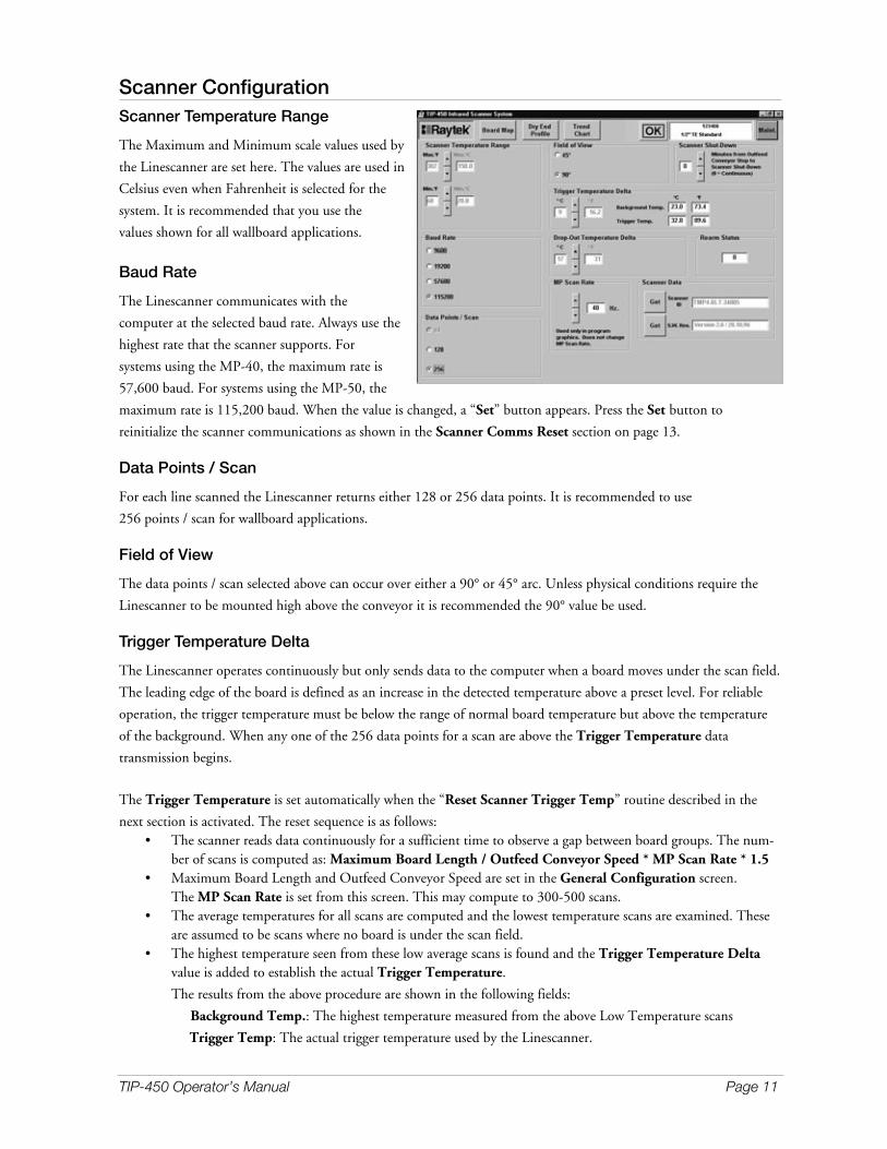
Scanner ConfigurationScanner Temperature Range
The Maximum and Minimum scale values used by
the Linescanner are set here. The values are used in
Celsius even when Fahrenheit is selected for the
system. It is recommended that you use the
values shown for all wallboard applications.
Baud Rate
The Linescanner communicates with the
computer at the selected baud rate. Always use the
highest rate that the scanner supports. For
systems using the MP-40, the maximum rate is
57,600 baud. For systems using the MP-50, the
maximum rate is 115,200 baud. When the value is changed, a “Set” button appears. Press the Set button to
reinitialize the scanner communications as shown in the Scanner Comms Reset section on page 13.
Data Points / Scan
For each line scanned the Linescanner returns either 128 or 256 data points. It is recommended to use
256 points / scan for wallboard applications.
Field of View
The data points / scan selected above can occur over either a 90° or 45° arc. Unless physical conditions require the
Linescanner to be mounted high above the conveyor it is recommended the 90° value be used.
Trigger Temperature Delta
The Linescanner operates continuously but only sends data to the computer when a board moves under the scan field.
The leading edge of the board is defined as an increase in the detected temperature above a preset level. For reliable
operation, the trigger temperature must be below the range of normal board temperature but above the temperature
of the background. When any one of the 256 data points for a scan are above the Trigger Temperature data
transmission begins.
The Trigger Temperature is set automatically when the “Reset Scanner Trigger Temp” routine described in the
next section is activated. The reset sequence is as follows:• The scanner reads data continuously for a sufficient time to observe a gap between board groups. The num-
ber of scans is computed as: Maximum Board Length / Outfeed Conveyor Speed * MP Scan Rate * 1.5• Maximum Board Length and Outfeed Conveyor Speed are set in the General Configuration screen.
The MP Scan Rate is set from this screen. This may compute to 300-500 scans.• The average temperatures for all scans are computed and the lowest temperature scans are examined. These
are assumed to be scans where no board is under the scan field.• The highest temperature seen from these low average scans is found and the Trigger Temperature Delta
value is added to establish the actual Trigger Temperature.
The results from the above procedure are shown in the following fields:
Background Temp.: The highest temperature measured from the above Low Temperature scans
Trigger Temp: The actual trigger temperature used by the Linescanner.

12 TIP-450 Operator’s Manual
Drop-Out Temperature Delta
When the trailing end of the board group leaves the scanner field of view, the computer commands the Linescanner to
stop sending data and rearm itself for the next board arrival. When the average scan line temperature falls below the
Background Temp. + Drop-Out Temperature Delta the conditions for “End of Board” are met.
MP Scan Rate
The scan rate of the Linescanner depends on the model scanner used. The MP40 scans at 20 / second. The MP50
scans at 48 / second. This settable field does not effect the operation of the Linescanner but is used in the above
computation and also for various graphics functions within the program.
Scanner Shut-Down
The Linescanner can shut down when the dryer is not operating. Set the number of minutes from the time the dryer
outfeed conveyor shuts down until the power to the Linescanner is turned off. The Linescanner will automatically
restart when the conveyor is restarted.
Note: Set this value high enough to avoid nuisance shut-downs such as a temporary lock-out to clear board jams, etc. If the
value is set to “0” the conver running input is ignored and the scanner runs continuously.
Rearm Status
It is possible that the communications link between the computer and the Linescanner can be disrupted. If the
outfeed gates are firing and board data is received from the Linescanner, the Linescanner is automatically rearmed.
The rearm procedure occurs in the background without an indication on the screen. This field shows the number
of times the Rearm routine acted. It is intended as a trouble-shooting tool to indicate when there may be problem
with the Trigger and Drop-Out temperature settings. Up to 10 rearm events in a 24 hour period is not considered
excessive.
Scanner Data
Pressing the “Get” buttons will return the Scanner ID and Software Revision. These are trouble-shooting tools only.
TIP-450 Operator’s Manual 13
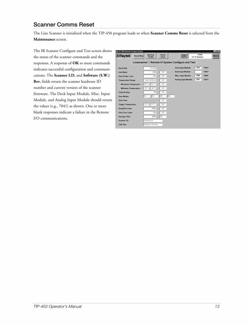
Scanner Comms ResetThe Line Scanner is initialized when the TIP-450 program loads or when Scanner Comms Reset is selected from the
Maintenance screen.
The IR Scanner Configure and Test screen shows
the status of the scanner commands and the
responses. A response of OK to most commands
indicates successful configuration and communi-
cations. The Scanner I.D. and Software (S.W.)
Rev. fields return the scanner hardware ID
number and current version of the scanner
firmware. The Deck Input Module, Misc. Input
Module, and Analog Input Module should return
the values (e.g., 7041) as shown. One or more
blank responses indicate a failure in the Remote
I/O communications.

14 TIP-450 Operator’s Manual
To change numeric values, do the following:
• Press the appropriate Text Box to
change to a white background
• Increase or Decrease the value with
the UP and DOWN arrow buttons.
The Single Arrow changes the value
by 1 digit. The Double Arrow
changes the value by 10 digits.
SetPoint DisplayTemperature Setpoint
Set the temperature Setpoint as displayed on
the Real Time Trend Chart.
Temperature Band
The allowable operating range is displayed on the Real Time Trend Chart. This value represents the width of the
allowable band. For example, if the Band is set to 10°, the range is ± 5°.
Trend Chart ConfigurationTrend Chart Maximum Temperature: the top range of the Trend Chart display.
This value is computed and automatically up-dated based on the values entered for Trend Chart Minimum Temp,
Number of Major Divisions and Degrees/Major Division. It cannot be changed using the arrow buttons.
Trend Chart Minimum Temperature
The minimum value of the Trend Chart display.
Use the UP and DOWN arrows to set the value. The Trend Chart background is set up on a grid with Major and
Minor Divisions. For example, if the number of Major Divisions is set to 8, and the Degrees / Major Division is set to
5, the Range of the chart is 40 degrees. (8*5 = 40). Each Major Division is labeled with a numeric value while the
Minor Divisions are unlabeled lines spaced between the Major Lines.
Number of Major Divisions - Degrees/Major Division
Use the UP and DOWN arrow buttons to select values that provide the Trend Chart span and resolution desired.
Graphics/Trend Charts

TIP-450 Operator’s Manual 15
Map DisplayMap Display Maximum Temperature
The top range of the Real Time Map display.
This value is computed and automatically up-dated based on the values entered for Map Display Minimum Temp
and Map Temperature Span. It cannot be changed using the arrow buttons.
Map Display Minimum Temperature
The minimum value of the Real Time Map display temperature spectrum.
Use the UP and DOWN arrows to set this value.
Map Temperature Span
The Span of the Real Time Map display temperature spectrum.
Use the UP and DOWN arrows to set this value.
End Profile ConfigurationEstablishes the parameters used for the Dry End Profile display.
End Profile Maximum Temperature
The top range of the Dry End Profile display. This value is computed and automatically up-dated based on the
values entered for End Profile Minimum Temp and End Profile Temperature Span. It cannot be changed using
the arrow buttons.
End Profile Minimum Temperature
The minimum value of the Dry End Profile display temperature spectrum. Use the UP and DOWN arrows to set
this value.
End Profile Temperature Span
The Span of the Dry End Profile display temperature spectrum. Use the UP and DOWN arrows to set this value
Board/Deck Average
The response of the Dry End Profile display data from a number of boards can be averaged presenting a time-damped
value. This value represents the number of boards that are used for averaging purposes. Permissible values are from
1 to 10. Use the UP and DOWN arrows to set this value.
Show/Hide Average
A dashed line representing the average temperature for all decks can be displayed on the Dry End Profile. This is
useful in showing those decks or areas that are above and below the overall average. This display can be toggled On
and Off by pressing the display status button. The status is shown by either ”Showing” or “Hidden” on the button.

16 TIP-450 Operator’s Manual
Temperature LocationThe board temperatures are measured at the scanner location which is downstream from the dryer discharge. Changes
in ambient temperature, board thickness, board weight, and the length of time that the boards have been out of
the dryer, are all combined to result in a net surface temperature drop that occurs before the boards actually reach
the sensor.
A single, fixed infrared sensor is located on the middle deck at the dryer discharge. This sensor continuously reads a
narrow band of temperature down the length of the board. When that individual board reaches the main scanner the
same band of board is compared to the data from the fixed sensor and a compensation profile is generated. This
compensation is applied to all boards, correcting all board temperatures to what they were at the dryer discharge.
Scanner Location
Select this option to read TRUE (uncompensated) temperatures as seen at the scanner location.
Dryer Discharge
Select this option to read COMPENSATED temperatures as seen at the dryer discharge.
Drive Chain LocationThe Real Time Map and Dry End Profile displays show the relationship of the boards to the dryer drive
configuration. Press this Icon to toggle the location of the drive chains as viewed from the dry end of the dryer.
Board Flow DirectionDepending on the location of the console in relationship to the dryer discharge conveyor, the leading edge of the
boards should be either on the left or right side of the screen. Select the appropriate option button depending on
whether the operator sees the board streams flowing from Left to Right or Right to Left.

TIP-450 Operator’s Manual 17

18 TIP-450 Operator’s Manual
Change Access CodesTo gain access to the maintenance areas of the system, a 4-digit code is required. You can change codes at any time
once access has been gained by entering the existing codes. The figure below shows the system when Administrator
access has been entered. With Administrator access, it is possible to change either the Supervisor or Administrator
access codes. If only Supervisor access has been previously obtained, a similar screen is shown with only the
Supervisor options visible. The procedures are the same for both access levels.
When this screen opens, a single entry field is
shown. Enter a new 4-digit code using the touch
screen keypad. When 4 digits are entered, a second
entry field appears. Reenter the same code. If the 2
codes match, the advisory screen appears as shown
above. Pressing OK accepts the new code and
saves them to a data file.
If the codes do not match, a message to that effect
is displayed along with an Exit button. The origi-
nal codes are retained. Pressing the Maintenance
Main Menu Change Access Codes button will
restore this screen shown at right for another try.
The system is shipped with the following default access codes:
Supervisor 1111
Administrator 2222
It is recommended that you change these default codes once the original system installation is complete. If the codes
are misplaced it is possible to restore the defaults. The access codes are stored in a file — sk.dat. Also included in the
program directory is a backup file sk.bak.
To restore the defaults:
1. Exit the TIP-450 program
2. Using Windows Explorer
• Delete the file sk.dat
• Create a copy of sk.bak by using the Edit/Copy and Edit/Paste functions of Explorer. A new file, Copy of
sk.bak, is created.
• Rename this file sk.dat.
• Restart the TIP-450 program. The original default codes shown above are loaded from the newly created
sk.dat file.

TIP-450 Operator’s Manual 19
Filter ChangeAir filters are installed on the Linescanner Cabinet and Main Console to provide clean air to the system. The
Linescanner lens must remain clean to function properly. The cabinet is pressurized with clean air that flows out the
slot in the bottom of the cabinet, preventing dust from reaching the Linescanner lens. It is important that the filters
not become plugged allowing the lens to become covered with dust.
The system provides a filter change reminder. When the filter change is due, the message box appears on the normal
operating screen. To close the message box press OK. Note: Until the filter change is acknowledged the message box reappears every 60 minutes.
Filter Change StatusThis area shows the number of days until a filter change is due. When a new filter is installed, press the New Filter
Installed button to reset the day counter.
Filter Interval Set
Set the number of days between filter changes required. Under normal operating conditions 30 to 60 days is the
expected life of the filter. When a new interval is set, you can reset the counter by pressing the New Filter Installed
button. For replacement of air filter media, please contact Raytek.

20 TIP-450 Operator’s Manual
As a section of the board leaves the dryer, the surface temperature begins to drop. This is due to the loss of heat from
the board surface to the surrounding air as well as transfer of the heat from the surface regions to the board core which
lags behind the surface temperature rise as drying progresses. Changes in ambient air temperature with the seasons as
well as the thickness and density of the board effect the rate at which this surface temperature drop occurs.
A single, fixed-head Infrared sensor is installed on one of the middle dryer decks to continuously measure the
temperature of a narrow band near the center of one of the boards. This temperature data is compared to the data
from the same band of the boards as measured by the MP50 Linescanner when it arrives at the Linescanner location.
This data is used to compensate the temperature readings from all decks, correcting for the variations that result from
differences in board thickness, density and ambient temperature.
For the system to work properly, the Fixed Head Sensor and Linescanner must compare the temperatures from the
same narrow band of wallboard. Once the Fixed Head Sensor is located at the dryer discharge, the alignment is
accomplished by marking the sensor location and setting the Linescanner data to match.
A thermal mark is made on the board at the dryer discharge by making a water streak on the board at the dryer
discharge that matches the sensor location. This will result in a clearly defined strip of low temperature as viewed with
the Real Time Map screen. With this information, the proper location for the compared board strip can be defined
from the Board Map screen.
Installation Warning1. The Fixed IR Sensor has an operating range up to 185 degrees Fahrenheit. To
avoid damaging the Fixed Sensor, do not install near the exhausted heat streamof the end seals at the output of the dryer. The typical operating temperature ofthe Fixed IR Sensor is 165F.
2. The Fixed IR Sensor assembly is air purged to prevent gypsum dust build-up onthe internal lens and mirror. Adjust the flow rate of the TIP450 Airpurge Assemblyto 30 SCFH on the rotameter.
3. See Drawing 97901-1, page 41 for further information.
The following pages show the procedure for aligning the scanner data with the fixed head sensor.
Fixed IR Sensor Setup

TIP-450 Operator’s Manual 21
Fixed IR Configure and Test This screen area shows the status and resultant calculations for the temperature compensation system. None of the
values can be set by the operator but are presented for maintenance and troubleshooting purposes.
Fixed Hits
The data from the fixed sensor is acquired several times per second. This field shows the number of valid data points
read for the current board.
Fixed Yint
The Y axis intercept of the linear line that describes the temperature profile of the board after it has completed it’s pas-
sage under the fixed sensor. This value is in °C.
Fixed Slope
The numeric slope of the linear line that describes the temperature profile of the board after it has completed it’s pas-
sage under the fixed sensor. A dimensionless number.
Scanner Yint
The Y axis intercept of the linear line that describes the temperature profile of the board after it has completed it’s pas-
sage under the scanner. This value is in °C.
Scanner Slope
The numeric slope of the linear line that describes the temperature profile of the board after it has completed it’s pas-
sage under the scanner. A dimensionless number.
The above data is used to establish leading and trailing edge temperatures for the tested region. This data is used to
automatically apply temperature correction for all boards leaving the dryer.

22 TIP-450 Operator’s Manual
Sensor ConfigurationUse this screen to set parameters that control the operation of the fixed sensor alignment and fixed sensor operation.
Measured Temperature
Real time data showing the temperature read by the fixed sensor.
Trigger Status
Data from the fixed sensor is acquired and analyzed only when a board is detected under the sensor. ON indicates
that a board is under the sensor while OFF indicates a gap between boards.
Trigger Temperature Setpoint
The temperature above which the sensor will consider a board being present. When there is no board under the sen-
sor, it reads the temperature of the passive metal target installed immediately below the sensor. Establish this value by
observing the Measured Temperature during normal operation. To adjust manually, set the Trigger Temperature
Setpoint midway between the lower target temperature and higher board temperature. The setpoint is adjusted by
touching the text box to highlight it and using the “+” and “-” keys. To enable the TIP450 software to control the set-
point, select the enabled box within the Auto Trigger Setpoint section.
Fixed Sensor Deck #
The physical deck location of the fixed sensor. This data is used to identify the correct boards for use in data
comparison. The Deck # is adjusted by touching the text box to highlight it and using the “+” and “-” keys.
ImportantThe following alignment procedure normally, is only required once during original commissioning of the system. If the position of the Fixed IR Sensor changes at any time it is necessary to repeat the procedure.
Align Fixed Sensor
An ON/OFF toggle control to enable the system administrator to properly align the data from the scanner with the
fixed sensor. Turn this feature ON during the alignment process.
Complete the Alignment Procedure:
1. Turn on the alignment system by toggling the Align Fixed Sensor button ON.
2. While a board is passing under the fixed sensor, draw a heavy line with a dark wax crayon immediately under thesensor location. This dark line will show up on the Board Map screen due to the higher emissivity of the line.
3. After the board is marked go immediately to the display screen for the system. Call the Board Map screen. TheBoard Map screen will have changed to include an Align area at the right of the screen as shown on the next page.If the top button on the Align area is green and indicates “Holding Push to Run,” touch the button so it is lightgray and reads “Waiting for Board.”
4. When a marked board is completely scanned, the Board Map display freezes and a double dotted line appears.
5. Use the UP and DOWN arrow systems to center the double dotted lines around the dark streaks that result fromthe line on the board. The numeric value between the UP and DOWN arrow buttons indicates the thermal datapixel location of the selected path.

TIP-450 Operator’s Manual 23
6. The procedure can be repeated if necessary, but normally a single alignment is all that is necessary.
7. Return to the Fixed IR Sensor Setup screen and turn the Align Fixed Sensor button OFF.
The Board Map Screen below shows the Fixer IR Sensor Alignment system activated.
5 123 74.4 143

24 TIP-450 Operator’s Manual
Analog InputsThree analog input channels are provided with the system. They are hardware configured to receive 4-20mA signals.
The Fixed IR Temperature has been described earlier. The Outfeed Conveyor Speed input is provided in the event
that the speed of the outfeed conveyor is changed as the production line speed varies. The third channel is a spare.
This screen provides scaling and configuration capabilities
Channel
The hardware input channel to the CBNet
module for each channel. See the system
diagrams for hardware assignments. Adjust the
channel value shown here to match the hardware
configuration.
Zero Offset (ma)
The 4-20mA analog signal is converted by the
hardware to a numeric value. At 0 transmitter
output, a 4 mA signal is generated. Set this value
to match the ma signal with 0 transmitter output.
Span (Engineering Units)
Set this value to provide the correct span reading depending on the type of transmitter used. For example: if the
Conveyor speed transmitter provides 20 mA at 300 ft. per minute, enter a value of 300.0.
Damping Seconds
The actual analog signals can present “noise” to the system, either due to small but rapid changes to the measured
signal or due to electrical interference to the signal. The Damping Seconds refers to the damping time constant (in
seconds) applied to the signal. Damping is accomplished by applying first order math to the input signal. The
equation for response to a step change input is:
mv = (1-e)(-t/T)
Where: e = difference between indicated and measured signal
t = elapsed time since step change
T = Damping Seconds
For most inputs used with the TIP-450 system, a Damping Seconds = 0 is acceptable.
Raw Data (ma)
This field displays the actual measured signal in milliamps. This field is read only and cannot be changed.
PV (Engrg. Units)
This field displays the computed measured value displayed in actual engineering units such as °F. Offsets, scaling and
damping (if used) are applied. This field is read only and cannot be changed.
9.84

TIP-450 Operator’s Manual 25
Multiplier
Change the numeric values by touching the appropriate text box to highlight the values. Select a multiplier with the
Multiplier option buttons. Each successive touch the the UP and DOWN arrows will change the value accordingly.
Analog Inputs
The small square to the right of the Analog Inputs label flashes each time the inputs are read. This is an indication
that the analog system is working properly.
Digital I/OA Digital I/O system provides information regarding the status of the drop gates, other inputs and outputs for alarm
signal devices and signals to the take off system PLC (if utilized). This screen shows the real time status of the various
digital I/O signals and allows their status to be forced.
The status for each dedicated inputs as well as spares is indicated by the status text box. During normal operation the
signals are read or controlled by the system.
It is possible to force the status of any input or
output by touching the OFF or ON option
button for each signal. Once forced to a condition
it will remain in that state until:
• This screen is removed from view.
• The “Clear All Forces” button is pressed.
• The individual bit option “READ” is
selected.
While a Force is active, the status area at the right
of the screen is visible. If there are no forces
currently in effect it remains hidden.
The Force feature can be used to test alarm signal
circuitry and the inertia to the take-off system.

26 TIP-450 Operator’s Manual
Filter ChangesChange the air filters on the Scanner Enclosure and Computer Enclosure as scheduled. Failure to change the filters
when required will result in dust accumulation on the scanner lens window and a loss of data accuracy. Usually the fil-
ters will only require cleaning and not replacement.
Scanner WindowWhen changing the Scanner Enclosure filter, check the scanner lens window for dust. Shining a flashlight on the lens
from below will clearly show if the window is clean.
The scanner window must be kept as clean as possible. Any foreign matter on the window will affect the accuracy of
the measurements. Be sure to take care when cleaning the scanning window; it can easily be scratched. Please observe
the following:
1. Lightly blow off lose particles.
2. Gently brush off remaining particles with a soft camel hair brush.
3. Clean remaining dirt using a soft cotton cloth dampened in distilled water. DO NOT RUB.
4. To remove finger prints or other grease, gently wipe with a soft cloth dampened in a mild soap or distilled watersolution.
5. Do not use any cleaners that are destructive to plastic materials like Teflon or Polyamide. Moreover, you shouldavoid getting any liquid in areas surrounding the window film.
If the Scanner Window is scratched or damaged it can be replaced following the procedures in the Maintenance
section of the Raytek OPERATOR’S MANUAL. Use the procedure for Film Type B. The Optional Air Purge Collar
may or may not be installed on your scanner.
WarningWhen replacing the Scanner Window do not touch the 1” diameter mirror that may be visi-ble on the rotating scanner element. The optical coating is easily damaged.
Replacement scanner windows are available from Raytek.
Routine Maintenance

TIP-450 Operator’s Manual 27
The remote Digital and Analog I/O are acquired and manipulated via an RS-422 network of individual I/O modules.
The normal control and communications of the network is imbedded in the main TIP-450 software. A separate
program called Cbcom is used in the event of module replacement or for system troubleshooting.
Running CBComTo run CBCOM, complete the following:
1. Terminate the TIP-450 program. Failure to doso will result in improper communicationssince the TIP-450 routinely uses the same com-munications ports.
2. From the Windows NT Taskbar select“Cbcom”
3. After a brief Intro Screen the window on theright will appear:
The normal system default communications
values are:
COM Port: COM 2
Baud Rate: 9600 bps
Address: 255[dec] FF[hex]
If the settings in CBCom do not match these values, there will be no details on each remote IO system module (exam-
ple: 7041...). Click on the COM Port menu item at the top of the window. The window below will display.
Select settings to match the display on the left.
Click the “OK” button to close the window and return to the
previous display.
It is necessary to select the Search menu item to reinitialize the
network search.
7041 1[1] 9600 14*DI 7050 2[2] 9600 7*DI / 8*DO 7017 17[11] 9600 +/ -5V
Double-click description
Appendix A: CBComm Communications Utility
Double-click description

28 TIP-450 Operator’s Manual
General Notes for Module Configuration
The RIO system modules RIO-01, RIO-02 and RIO-03 share a parallel data bus arrange-ment. Each module is identified by it’s unique address. The CBNet modules are suppliedwith a default address of 01. If a replacement module is installed, it is necessary to set theaddress before it can properly communicate with the system.
The assigned addresses for each module are:
Name Type Description Address
dec[hex]
RIO-01 CB-7041 Drop Gate Status 01[01]
RIO-02 CB-7050 Misc. Digital IO 02[02]
RIO-03 CB-7017 Analog Input 17[11]
The address and other configuration settings are performed using CBCom.
To avoid address conflicts when setting up a new module, disconnect the green connector topins 1 through 10 from the other 2 modules in the system. This prevents those modules fromcommunicating with the system. The connectors can be removed and replaced with power tothe system.

TIP-450 Operator’s Manual 29
Module Details - RIO-01 (7041 - 14*D)The following screen shows the status of the RIO-01 module that detects the status of the unloader drop gates.
Status Indicators
The Digital Input Indicators 0-13 show the ON-OFF status of the 14 available inputs.
Inputs 14 & 15 as well as Digital Outputs 0-15 are not valid.
“Running!” Indicators
When the display indicates “Running!”, the module is sending valid data to the PC. If the modules is not sending data
the display indicates “Stopping!”.
Configuration Setting
The UP and DOWN buttons are used to set the Address for the individual module. The Checksum and Baudrate
items are selected from the available list. If the configuration is changed, it is necessary to press the “Setting” button
to write the new configuration to the module EEPROM and to reinitialize the system by selecting “Search” from the
Main Menu (See Fig. 1).
Note: The Address is displayed in Decimal (not Hex) format.

30 TIP-450 Operator’s Manual
Module Details - RIO-02 (7050 / 8*DO)The following screen shows the status of the RIO-02 module that detects the status miscellaneous inputs and controls
the outputs.
Status Indicators
The Digital Input Indicators 0-6 show the ON-OFF status of the 7 available inputs. Inputs 7 to 15 are not valid.
The Digital Output Indicators 0-7 show the ON-OFF status of the 8 available outputs. Outputs 8 & 15 are not valid.
“Running!” Indicators
When the display indicates “Running!”, the module is sending valid data to the PC. If the modules is not sending data
the display indicates “Stopping!”.
Configuration Setting
The UP and DOWN buttons are used to set the Address for the individual module. The Checksum and Baudrate
items are selected from the available list. If the configuration is changed, it is necessary to press the “Setting” button
to write the new configuration to the module EEPROM and to reinitialize the system by selecting “Search” from the
Main Menu (See Fig. 1).
Note: The Address is displayed in Decimal (not Hex) format.

TIP-450 Operator’s Manual 31
MODULE DETAILS - RIO-03 (7017 - 8* AI)The following screen shows the status of the RIO-03 module that reads the analog inputs.
Channel Enable / Disable Setting
Click the check box to disable or enable each channel. It is recommended to “Select All”.
“Running!” Indicator
When the display indicates “Running!”, the module is sending valid data to the PC. If the modules is not sending data
the display indicates “Stopping!”.
Configuration Setting
The UP and DOWN buttons are used to set the Address for the individual module. The Checksum and Baudrate
items are selected from the available list. If the configuration is changed, it is necessary to press the “Setting” button
to write the new configuration to the module EEPROM and to reinitialize the system by selecting “Search” from the
Main Menu.
Note: The Address is displayed in Decimal (not Hex) format.
The Input Range, Data Format, Baudrate, and Checksum should be set to the values shown above.

32 TIP-450 Operator’s Manual

TIP-450 Operator’s Manual 33
The NT system has been modified to allow the TIP-450 system to automatically load when the computer system
starts. This bypasses the normal Logon procedure for NT.
User Configuration
Username: TIP
Password: tip
Group: Users
To permit the system to automatically boot, the NT Initialization has been modified as follows:
• Launch REGEDIT.EXE from the Run dialog.
• Expand the branches in this order:
HOTKEY_LOCAL_MACHINE\Software\Microsoft\WindowsNT\CurrentVersion\WinLogon
• With WinLogon selected, see an entry called DefaultUserName in the right pane. Double-click on it and
enter the name of the user account you want the system to automatically log on as TIP.
• From the Edit menu, select New|String Value and enter AutoAdminLogon. Double-Click and set value=1
• Go back to Edit menu and create a second string value called DefaultPassword. Double-Click on it and
make its value the password for the account you'd like to use. In this case the DefaultPassword = tip
• Close the Registry and reboot the system.
This causes NT to go directly to the Desktop without requiring a log-on.
To log on as another user when this auto log-on has been implemented:
Either hold down the Shift key during boot-up.
Or
From the Shut-down menu click "Close all programs and log on as a different user" while holding down the
Shift Key.
Notes regarding the AutoLogon feature
• If the Override system is used to log on as Administrator, the system will reboot to Administrator. It is
necessary to use the Override again and change to TIP as the user. Subsequent boot-up will employ the
Autologon feature to the TIP450 system.
• The system as supplied has a null Administrator password. Your I.S. manager may want to change this
configuration.
Appendix B: Special Configuration of Windows NT 4.0

34 TIP-450 Operator’s Manual

TIP-450 Operator’s Manual 35
The required data and program files are as follows:
The Operating ProgramTIP450.exe
Configuration Data Filesaidata.dat fielddemo.dat scanCfg.dat
alarmdat.dat genlCfg.dat sk.bak
aodata.dat grafcfg.dat sk.dat
commport.dat grafcfgc.dat tempComp.dat
Historical Data File Systems<DIR> Profile
PHnnnnnn.dat - Numerous files with sequential numbers. Each file contains profile history data for a 6 day period.
<DIR> Trend
YY-MM.dat - Numerous files. A separate file for each month.
The files are automatically installed as part of the Windows Setup installation. The Historical files are created as
required by the system while in operation.
The default setup is to install the system to the following directory structure:
• <drive>\program files\tip450
tip450.exe + realtime.dat
• <drive>\program files\tip450\profile
historical profile data - PHnnnnnn.dat
• <drive>\program files\tip450\trend
trend history monthly files - yy-mm.dat
• <drive>\program files\tip450\cfgdat\*.dat
configuration data files as listed above
Operations and Maintenance ManualsIn addition to the hard copy manual, the Operator’s Manual is included on the distribution CDROM in PDF
format. Viewing the manual files requires Adobe Acrobat Reader. The Acrobat Reader system is provided in the
<drive>\Acrobat directory on the CDROM. Install Acrobat Reader by running <drive>\Acrobat\setup.exe.
Appendix C: Program and Data Files & General Information

36 TIP-450 Operator’s Manual

TIP-450 Operator’s Manual 37
Add Text here about the start up procedures -
1. Scanner–Using drawing 97901-2b as a reference, examine the scanner mounting arrangement:a. No obstacles in the viewing area.b. Correct height from boards.c. Downstream of Cascade Section.d. No inspection lights in scan area.e. No excessive vibrations or movement.f . No stress on cables.g. Check wiring with drawing 27901-2.h. Fan running – when powered up.
2. Fixed IR–Using drawing 97901-1 as a reference, examine the Fixed IR mounting arrangement:a. Mounted on the center deck.b. Check wiring with drawing 27901-7.c. Ensure the distance in from the board edges is > 12 inches.d. Ensure that boards have at least a six-inch gap at the sensor location.e. Ensure the air purge is providing sufficient airflow to purge the lens (30 on the rotameter).
3. Remote I/O–Using drawings 27901-6 and 27901-3 as a reference, examine the 7041 drop gate I/O moduleand ensure that wiring and jumpers are correct.a. Ensure the jumper from VS+ to Init Com and both jumper bars are on relay modules.b. Ensure the signals are not from unsourced triac output PLC card because these opto relays will not provide
enough impedance to work off of unloaded triac outputs.c. Input signals should be electrically shared with the drop gate outputs from the process.
4. Main Cabinet–Using drawing 27901-7 as a reference, ensure power inputs and all other field wiring are cor-rectly landed in the main console.a. L1–Hot on CB1b. L2–neutral on #5
5. Ensure PC cables are connected properly:a. The scanner serial cable on Comm1.b. RS-485 to RS-232 converter 7520 blue module cable on Comm 2.
6. Power Up–Power the following components:■ The main console with the circuit breaker (CB1) switch:
a. 24VDC power should show on blue module lights.b. Fans should start up.
■ The PC and the monitor:a. If the monitor does not power up automatically with the PC, push the button on the back of the
monitor for “power on.”b. PC should boot up to Windows 2000 password screen.c. Push enter to get to the main operating screen.
7. 7000Util software–Start the software. Scan on Comm2 and ensure all three blue modules appear.a. 7041=1, 7050=2, 7017=Hex11/Dec17. *(7041=3 for 16 deck dryers)
Double click on the 7401 module to see the digital inputs.b. If no signal changes, go to 7041 drop gate I/O module location and look for relay lights to show the active drop
gates.c. If no lights appear check the signals with a DVM to check for proper input voltages.
Double click on the 7017 module and confirm it is set to Hex11/Dec17 and +/-5V.d. Voltage should be between 1 and 2.5 volts on CH1. (1V=0˚C, 5v=200˚C)e. All other channels are unused.f . Close 7000 UTIL Software
8. DataTemp MP software–Start the software, Scantalk Utility, and set the following parameters:a. Comm1
Appendix D: QuickStart Startup Procedures

38 TIP-450 Operator’s Manual
b. Select 115,200 Baud Rate and press OK.c. In the command prompt, type TR2 and press Enter to set the scanner for “sub-range” temperatures.d. Then PS and press Enter. (parameter store)e. Then FI066 and press Enter.f . Then PS and press Enter. (parameter store)g. Close DataTEMP MP Software.
9. TIP-450 software–Start the software. The scanner comms should show OK on screen and the I/O modulesshould show up on the top right of the initializing screen.If no scanner comms, ensure the following:a. Under Maint/Digital I/O: if necessary Force the scanner power relay, then go back to Read. Then look at relay
PHOE2 on TB1 in Main Cabinet for light (scanner power relay).b. Under Maint/ Scanner Configuration: ensure the baud rate is set at 115,200, the Datapoints are at 256, and the
View Angle is at 90˚.c. Under Maint/Set Comm Ports, ensure Scanner is on Comm1 and I/O on Comm 2.d. Reset Scanner Comms.e. If there are still no scanner communications, check wiring and signals at scanner location and main cabinets.
10. Drop Gate Signals–Check the following:a. On the Maint/Digital I/O screen check for drop gate signal display.b. If no signal, refer to step 7.c. Ensure the observed drop gate signals correlate to the proper deck.
11. Outfeed Length:a. Determine the distance from the drop gate section to the linescanner. b. In the General Setup screen input the value into the Outfeed Length space.
12. Timer Value:a. Time the drop gate event until the lead edge of that board arrives under the scanner (ensure this time is roughly
the same for all decks). b. Subtract 2 to 3 seconds from the shortest deck timec. This is your timer value in General Setup. d. Adjust your timer value by setting the Outfeed Speed until the timer is correct.
13. Deck Tracking–Ensure tracking is correct:a. Observe countdown timers on the General Setup screen.b. The times should go to 0 two to three seconds before the deck’s board arrives at the scanner.
14. Confirm that deck 1 is on top or bottom. If needed, change in General Setup.15. Confirm drive chain location on dryer.
a. Change the drive chain location by clicking on the dryer drawing in the General Setup Screen.b. Confirm on End Profile screen.
16. Confirm and set the following settings on the General Setup screen.a. F/C e. Maximum Board Lengthb. Feet/Meters f . Dryer Location = compensated c. 12/24 Hour g. Scanner Location = uncompensatedd. Board Flow Direction h. Printer hooked up?
17. Analog I/O screena. Check for Fixed IR reading in C.b. Confirm reasonable accuracy with hand-held sensor.c. Adjust S potentiometer on sensor assembly transmitter if significantly off. d. If no reading, use DVM to troubleshoot with drawing #27901-4.
18. Maintenance Digital I/O screena. Check for signal input from outfeed conveyor run portion of the screen.
19. Scanner Configuration screen–Confirm the following settings.a. Temp Range: 20–100˚ C e. Baud Rate: 115,200b. Trigger Temp: 9˚ C f. Datapoints: 256c. Drop Out Temp: 12˚C g. Field of View: 90d. If Conveyor running signal is provided:
5 minutes (otherwise leave at 0)

TIP-450 Operator’s Manual 39
20. Maintenance Screena. Click reset Scanner Trigger Temp. to set the background temp.b. When finished scanning click OK.
21. If boards are not completely scanned:a. Reset Scanner Trigger Temp.
■ If the problem persists do the following:b. If lead edge board is missing: adjust the Trigger Temperature Delta in Scanner Setup screen.
■ 9 is the average setting ■ A lower value makes the system more sensitive to the presence of the board■ A higher value eliminates false triggers on belts
c. If trailing edge of board is missing: adjust the Dropout temperature Delta in the Scanner Setup Screen.■ 12 is the average setting■ A lower value makes the system less sensitive to trailing edge board dropout.■ A high value makes it more sensitive.
22. Adjust settings on the Graphic/Trend Charts screen: Go to Graphics/Trend Charts.a. Adjust Minimum Temperatures and then Spans to maximize the screen resolutions for all three operating
screens. Repeat as necessary while observing operating screens.23. Fixed IR Sensor Setup:
a. Establish distance of Fixed IR Sensor location inside of board edge.b. In the Fixed Sensor Setup screen, set fixed deck to Sensor Deck location.c. Set Align Fixed Sensor to ON.d. Go to Board Map screen and wait for boards from the Fixed IR deck to run through; screen
automatically freezes.e. Use up/down arrows on right side of display to align dotted lines over approximated
measurement band. f . Set Press to Run and return to fixed IR Sensor Setup, set Align Fixed Sensor back to OFF.
24. Scanner Orientation: a. Have someone use their hand or an object ot indentify right board from left board to ensure scanner orienta-
tion is correct.b. If orientation is backwards, go to the scanner cabinet, remove scanner cables, remove 4 allen screws, turn scan-
ner 180˚, reinstall scanner and cables.25. Product Recipe Database: Go to Graphics/ Trend Charts
a. Delete all non-pertinent recipes.b. Use Add New Product to install recipes into database.
26. Setup the Start Menu Program to reboot into the TIP450 software: a. Move the cursor over the Taskbar at the bottom of the screen and right-click the mouse button.b. Select Properties, then click Start Menu Programs, and select Advanced.c. Under the Exploring/Start Menu find:
■ C:\Program Files\Raytek\Tip450\Tip450.exe (this displays a red and yellow icon)■ Right-click the mouse on the file, and select Create Shortcut.■ Right-click the mouse again on the new shortcut to TIP450 file and select Copy.
d. Under the “Exploring/Start Menu window, find:■ C:\Winnt\Profiles\...\Start menu\Programs\Startup.■ Right-click the mouse and paste the Shortcut to TIP450 file.
e. Reboot the PC. Following the password screen, it will auto-start into the TIP450 program.27. Create a desktop shortcut to TIP450:
a. Open Windows Explorer and go to C:\Program Files\Raytek\TIP450\Shortcut to TIP450.b. Copy and Paste that icon to the center of the desktop for easy touchscreen startup.
28. Set Power Save to Nevera. Go to Start, and scroll to Control Panelb. Click on monitor and set Power Save to Never.

40 TIP-450 Operator’s Manual
TIP-450 Overview Drawing

TIP-450 Operator’s Manual 41
TIP-450 Fixed IR Installation
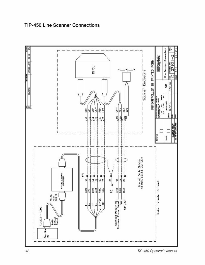
42 TIP-450 Operator’s Manual
TIP-450 Line Scanner Connections

TIP-450 Operator’s Manual 43
TIP-450 Scanner Installation

44 TIP-450 Operator’s Manual
TIP-450 Drop Gate/Clutch Impulse

TIP-450 Operator’s Manual 45
TIP-450 Remote I/O Wiring Drawing

46 TIP-450 Operator’s Manual
TIP-450 ain Panel TB1 Connections

TIP-450 Operator’s Manual 47
TIP-450 Phoenix Contact Modules

48 TIP-450 Operator’s Manual
TIP-450 16 Dwk RIO Module Wiring

TIP-450 Operator’s Manual 49


![[XLS] · Web view450. 90. 450. 900. 900. 225. 450. 450. 900. 450. 225. 270. 4.5. 450. 450. 450. 450. 450. 450. 450. 450. 450. 900. 450. 450. 450. 112.5. 900. 900. 450. 112.5. 450.](https://static.fdocuments.in/doc/165x107/5b3c17127f8b9a213f8d0b42/xls-web-view450-90-450-900-900-225-450-450-900-450-225-270-45.jpg)