Tinytag Radio Data Loggers - Gemini DataLoggers
32
Tinytag Radio Data Loggers Technical Manual
Transcript of Tinytag Radio Data Loggers - Gemini DataLoggers

Tiny
tag
Radi
o D
ata
Logg
ers
Tech
nica
l Man
ual
1 Tinytag Radio Data Logger Technical Manual
01
1.1 About this Document
This document describes the Tinytag radio data logger system.
This document also describes characteristics of the Tinytag Explorer and the Radio Gateway Service that is installed alongside this software used with radio loggers. All users are encouraged to upgrade to the latest version and only version 4.7 is described in detail.
2 Table of Contents
02
1 Tinytag Radio Data Logger Technical Manual 1
1.1 About this Document 1
2 Table of Contents 2
3 Radio Gateway Service Computer Requirements 3
4 Radio System Component Overview 4
4.1 Tinytag Explorer 4
4.2 Radio Gateway Server 5
4.3 Receiver 6
4.4 Radio Logger 6
4.5 Repeater 6
4.6 Receiver Cables 6
4.7 Mesh Network 7
5 Point-to-Point Radio 8
6 Receiver Confi gurations 9
6.1 Direct 9
6.2 Multiple Receivers 9
6.3 Multiple Computers Running the Radio Gateway Service 9
Receiver Confi guration (Continued) 10
Receiver Confi guration (Continued) 11
6.4 Repeater 12
6.5 Back-to-Back Receivers 12
7 Mesh Network Behaviour 13
7.1 Switching On a Device 13
7.2 Moving a Device 13
7.3 Starting the Radio Gateway Service 13
7.4 Switching On the Receiver 13
7.5 Redundant Routing 13
Mesh Network Behaviour (Continued) 14
Mesh Network Behaviour (Continued) 15
Mesh Network Behaviour (Continued) 16
7.6 Radio Confi guration 17
7.6.1 Adjusting the Radio Range 17
7.6.2 Receive Sensitivity 17
7.6.3 Transmit Power 17
7.7 Very slow logging intervals 17
7.8 Very fast logging intervals 18
7.9 Data organisation 18
7.10 Alarms 18
8 Buttons and Lights 19
9 Rapid Installation 20
9.1 Introduction 20
9.2 Receiver First 20
9.3 Nearby Loggers Next 20
9.4 Distance Order 20
9.5 Don’t Rush It 20
9.6 Transplanting the Network to a New Location 20
10 Troubleshooting 21
10.1 Tinytag Explorer Status Bar Indicator Flashes Red 21
10.2 Firewall Confi guration 21
11 Data Logging 22
11.1 No stopping 22
11.2 Time zones 22
11.3 Current Readings 22
12 Other Radio Gateway Functions 23
12.1 Modbus 23
12.2 Data Export 23
12.3 Proprietary Radio Gateway Service Protocol 24
13 Modbus 25
13.1 Properties and Registers 25
13.2 Devices 25
13.3 Expected Values 25
13.4 Unit Identifi ers 25
13.5 Function Codes 25
13.6 32-bit Values 25
13.7 Freshness 25
13.8 Device Connection 25
13.9 Missing Properties 26
13.10 Concurrent Connections 26
13.11 Modsak 26
14 Power 27
14.1 Batteries 27
14.2 Low Power Warnings 27
14.3 The Eff ect of the Mesh Network 27
15 Regulatory Compliance 28
Notes 29
3 Radio Gateway Service Computer Requirements
03
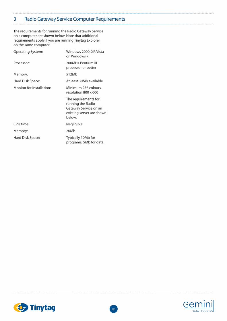
The requirements for running the Radio Gateway Service on a computer are shown below. Note that additional requirements apply if you are running Tinytag Explorer on the same computer.
Operating System: Windows 2000, XP, Vista or Windows 7.
Processor: 200MHz Pentium III processor or better
Memory: 512Mb
Hard Disk Space: At least 30Mb available
Monitor for installation: Minimum 256 colours, resolution 800 x 600
The requirements for running the Radio Gateway Service on an existing server are shown below.
CPU time: Negligible
Memory: 20Mb
Hard Disk Space: Typically 10Mb for programs, 5Mb for data.
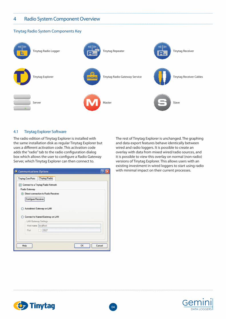
4.1 Tinytag Explorer Software
The radio edition of Tinytag Explorer is installed with the same installation disk as regular Tinytag Explorer but uses a diff erent activation code. This activation code adds the “radio” tab to the radio confi guration dialog box which allows the user to confi gure a Radio Gateway Server, which Tinytag Explorer can then connect to.
The rest of Tinytag Explorer is unchanged. The graphing and data export features behave identically between wired and radio loggers. It is possible to create an overlay with data from mixed wired/radio sources, and it is possible to view this overlay on normal (non-radio) versions of Tinytag Explorer. This allows users with an existing investment in wired loggers to start using radio with minimal impact on their current processes.
4 Radio System Component Overview
Tinytag Radio System Components Key
Tinytag Radio Logger
Tinytag Explorer
Server
Tinytag Repeater
Tinytag Radio Gateway Service
Master
Tinytag Receiver
Tinytag Receiver Cables
Slave
04
4 Radio System Component Overview (Continued)
05
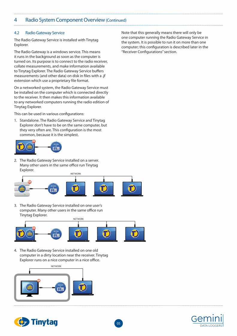
4.2 Radio Gateway Service
The Radio Gateway Service is installed with Tinytag Explorer.
The Radio Gateway is a windows service. This means it runs in the background as soon as the computer is turned on. Its purpose is to connect to the radio receiver, collate measurements, and make information available to Tinytag Explorer. The Radio Gateway Service buff ers measurements (and other data) on disk in fi les with a .jf extension which use a proprietary fi le format.
On a networked system, the Radio Gateway Service must be installed on the computer which is connected directly to the receiver. It then makes this information available to any networked computers running the radio edition of Tinytag Explorer.
This can be used in various confi gurations:
Note that this generally means there will only be one computer running the Radio Gateway Service in the system. It is possible to run it on more than one computer; this confi guration is described later in the “Receiver Confi gurations” section.
NETWORK
NETWORK
2. The Radio Gateway Service installed on a server. Many other users in the same offi ce run Tinytag Explorer.
3. The Radio Gateway Service installed on one user’s computer. Many other users in the same offi ce run Tinytag Explorer.
4. The Radio Gateway Service installed on one old computer in a dirty location near the receiver. Tinytag Explorer runs on a nice computer in a nice offi ce.
1. Standalone. The Radio Gateway Service and Tinytag Explorer don’t have to be on the same computer, but they very often are. This confi guration is the most common, because it is the simplest.
NETWORK
4 Radio System Component Overview (Continued)
Ideally the Radio Gateway Service would be left running 24/7 to allow it to collate all data. No measurements will be lost if the computer is shut down for up to 2 weeks (at a 10 minute measurement interval), however this will aff ect battery life and there may be a delay in displaying new measurements due to the need to retransmit cached measurements. If the Radio Gateway Service is shut down, it will detect any measurements that weren’t collated on their fi rst transmission and arrange retransmission. This ensures that no data is permanently lost.
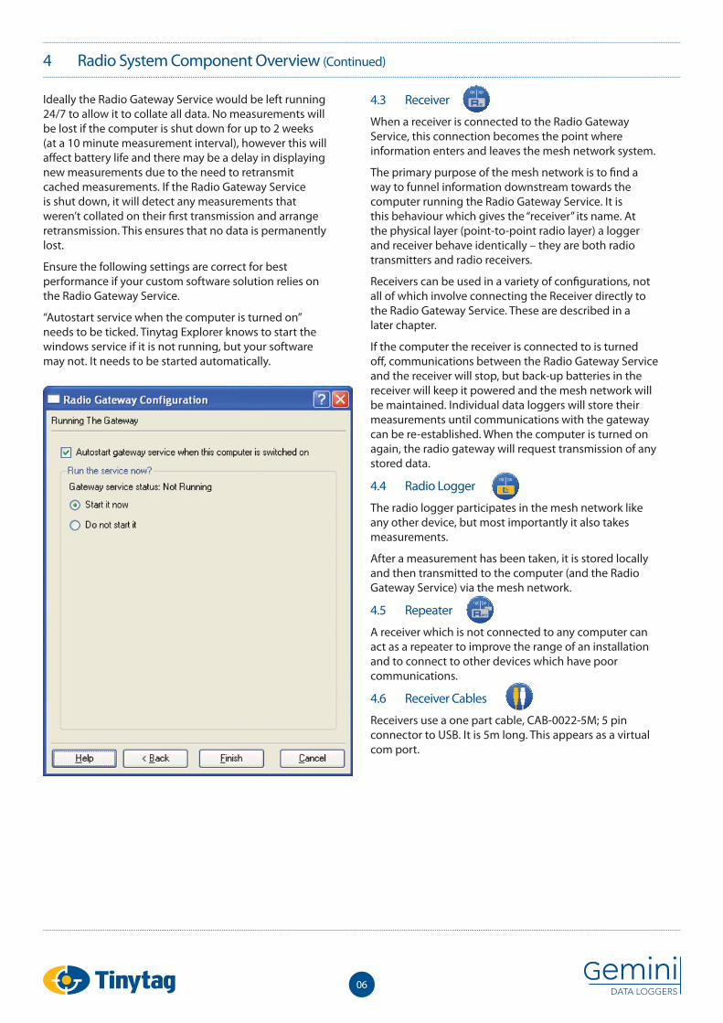
Ensure the following settings are correct for best performance if your custom software solution relies on the Radio Gateway Service.
“Autostart service when the computer is turned on” needs to be ticked. Tinytag Explorer knows to start the windows service if it is not running, but your software may not. It needs to be started automatically.
4.3 Receiver
When a receiver is connected to the Radio Gateway Service, this connection becomes the point where information enters and leaves the mesh network system.
The primary purpose of the mesh network is to fi nd a way to funnel information downstream towards the computer running the Radio Gateway Service. It is this behaviour which gives the “receiver” its name. At the physical layer (point-to-point radio layer) a logger and receiver behave identically – they are both radio transmitters and radio receivers.
Receivers can be used in a variety of confi gurations, not all of which involve connecting the Receiver directly to the Radio Gateway Service. These are described in a later chapter.
If the computer the receiver is connected to is turned off , communications between the Radio Gateway Service and the receiver will stop, but back-up batteries in the receiver will keep it powered and the mesh network will be maintained. Individual data loggers will store their measurements until communications with the gateway can be re-established. When the computer is turned on again, the radio gateway will request transmission of any stored data.
4.4 Radio Logger
The radio logger participates in the mesh network like any other device, but most importantly it also takes measurements.
After a measurement has been taken, it is stored locally and then transmitted to the computer (and the Radio Gateway Service) via the mesh network.
4.5 Repeater
A receiver which is not connected to any computer can act as a repeater to improve the range of an installation and to connect to other devices which have poor communications.
4.6 Receiver Cables
Receivers use a one part cable, CAB-0022-5M; 5 pin connector to USB. It is 5m long. This appears as a virtual com port.
06
4 Radio System Component Overview (Continued)
07
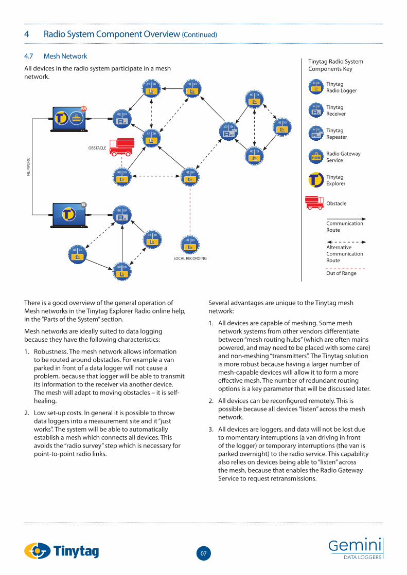
4.7 Mesh Network
All devices in the radio system participate in a mesh network.
Tinytag Radio System Components Key
There is a good overview of the general operation of Mesh networks in the Tinytag Explorer Radio online help, in the “Parts of the System” section.
Mesh networks are ideally suited to data logging because they have the following characteristics:
1. Robustness. The mesh network allows information to be routed around obstacles. For example a van parked in front of a data logger will not cause a problem, because that logger will be able to transmit its information to the receiver via another device. The mesh will adapt to moving obstacles – it is self-healing.
2. Low set-up costs. In general it is possible to throw data loggers into a measurement site and it “just works”. The system will be able to automatically establish a mesh which connects all devices. This avoids the “radio survey” step which is necessary for point-to-point radio links.
Several advantages are unique to the Tinytag mesh network:
1. All devices are capable of meshing. Some mesh network systems from other vendors diff erentiate between “mesh routing hubs” (which are often mains powered, and may need to be placed with some care) and non-meshing “transmitters”. The Tinytag solution is more robust because having a larger number of mesh-capable devices will allow it to form a more eff ective mesh. The number of redundant routing options is a key parameter that will be discussed later.
2. All devices can be reconfi gured remotely. This is possible because all devices “listen” across the mesh network.
3. All devices are loggers, and data will not be lost due to momentary interruptions (a van driving in front of the logger) or temporary interruptions (the van is parked overnight) to the radio service. This capability also relies on devices being able to “listen” across the mesh, because that enables the Radio Gateway Service to request retransmissions.
LOCAL RECORDING
NET
WO
RK
OBSTACLE
TinytagRadio Logger
TinytagReceiver
TinytagRepeater
Radio Gateway Service
TinytagExplorer
Obstacle
Communication Route
AlternativeCommunication Route
Out of Range
5 Point-to-Point Radio
08
Diff erent radio frequencies are used for diff erent countries.
869.8MHz Used in the EU. Devices using this frequency can be identifi ed by their part number ending –A. Older part numbers which do not have a single letter part number suffi x also use this frequency.
917.8MHz Used in Australia. Devices using this frequency can be identifi ed by their part number ending -B.
917.8MHz Used in USA, Canada. Devices using this frequency can be identifi ed by their part number ending -C.
Naturally, parts using diff erent frequencies can not interoperate.
The radio uses FSK modulation, with +/-32 kHz deviation.
The transmission power is <3mW in EU & Australia & <0.75mW in USA & Canada.
In free space the range is approximately 200m (75m for -C products).
These frequencies will easily penetrate most internal or external walls; however the range may be reduced.
Indoors the range is quite variable. It is usually reduced to between 30% and 80% of full range. However it will sometimes be increased, maybe up to double the nominal range, due to “lucky” refl ections off other buildings, steel roofs, etc. This variability works to the advantage of the mesh network because the unlucky majority will be able to relay their information via the lucky one with the extra-long range.
The radio system works well indoors and out. The frequencies will usually penetrate steel-walled rooms, through door seals, windows, ventilation etc. Even though the radio waves cannot penetrate a metal wall (whether a fridge, or corrugated iron shed), the signal will probably still get through gaps around door seals and other openings.
These frequencies are very slightly absorbed by water. Wet walls are not a problem, but the signal will not get through a room fi lled with shelves full of fruit, for example.
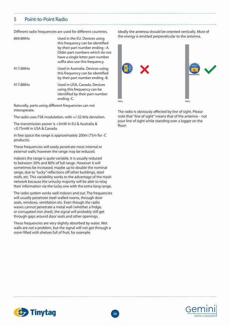
Ideally the antenna should be oriented vertically. Most of the energy is emitted perpendicular to the antenna.
The radio is obviously aff ected by line of sight. Please note that “line of sight” means that of the antenna – not your line of sight while standing over a logger on the fl oor!
WALL WALL
6 Receiver Confi gurations
09
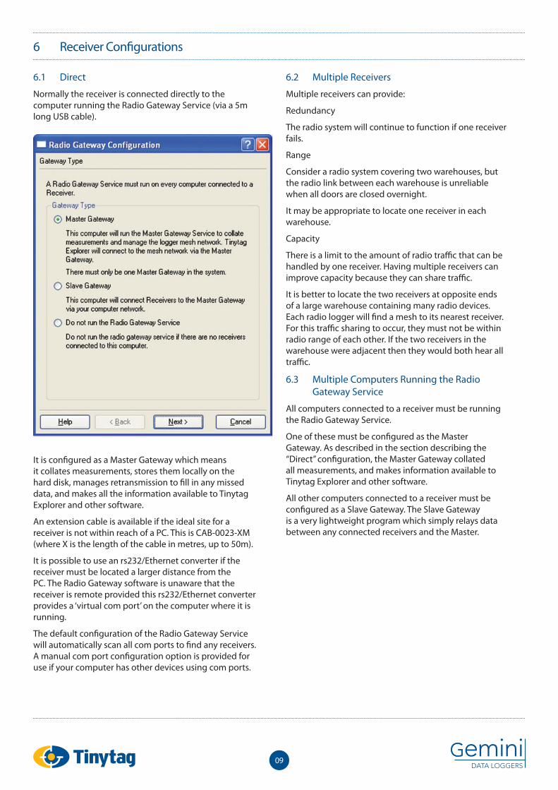
6.1 Direct
Normally the receiver is connected directly to the computer running the Radio Gateway Service (via a 5m long USB cable).
It is confi gured as a Master Gateway which means it collates measurements, stores them locally on the hard disk, manages retransmission to fi ll in any missed data, and makes all the information available to Tinytag Explorer and other software.
An extension cable is available if the ideal site for a receiver is not within reach of a PC. This is CAB-0023-XM (where X is the length of the cable in metres, up to 50m).
It is possible to use an rs232/Ethernet converter if the receiver must be located a larger distance from the PC. The Radio Gateway software is unaware that the receiver is remote provided this rs232/Ethernet converter provides a ‘virtual com port’ on the computer where it is running.
The default confi guration of the Radio Gateway Service will automatically scan all com ports to fi nd any receivers. A manual com port confi guration option is provided for use if your computer has other devices using com ports.
6.2 Multiple Receivers
Multiple receivers can provide:
Redundancy
The radio system will continue to function if one receiver fails.
Range
Consider a radio system covering two warehouses, but the radio link between each warehouse is unreliable when all doors are closed overnight.
It may be appropriate to locate one receiver in each warehouse.
Capacity
There is a limit to the amount of radio traffi c that can be handled by one receiver. Having multiple receivers can improve capacity because they can share traffi c.
It is better to locate the two receivers at opposite ends of a large warehouse containing many radio devices. Each radio logger will fi nd a mesh to its nearest receiver. For this traffi c sharing to occur, they must not be within radio range of each other. If the two receivers in the warehouse were adjacent then they would both hear all traffi c.
6.3 Multiple Computers Running the Radio Gateway Service
All computers connected to a receiver must be running the Radio Gateway Service.
One of these must be confi gured as the Master Gateway. As described in the section describing the “Direct” confi guration, the Master Gateway collated all measurements, and makes information available to Tinytag Explorer and other software.
All other computers connected to a receiver must be confi gured as a Slave Gateway. The Slave Gateway is a very lightweight program which simply relays data between any connected receivers and the Master.
6 Receiver Confi gurations (Continued)
10
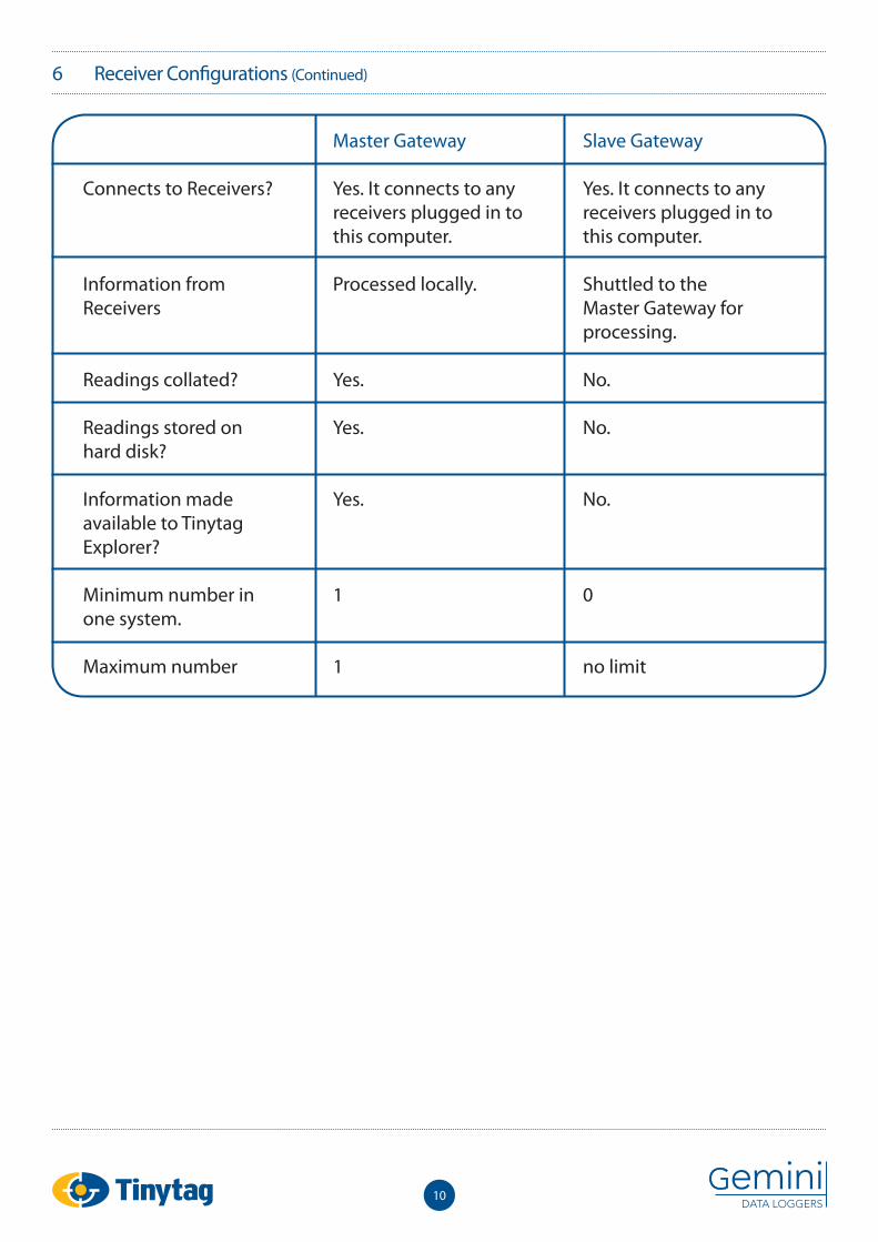
Connects to Receivers?
Information from Receivers
Readings collated?
Readings stored on hard disk?
Information made available to Tinytag Explorer?
Minimum number in one system.
Maximum number
Master Gateway
Yes. It connects to any receivers plugged in to this computer.
Processed locally.
Yes.
Yes.
Yes.
1
1
Slave Gateway
Yes. It connects to any receivers plugged in to this computer.
Shuttled to the Master Gateway for processing.
No.
No.
No.
0
no limit
11
6 Receiver Confi gurations (Continued)
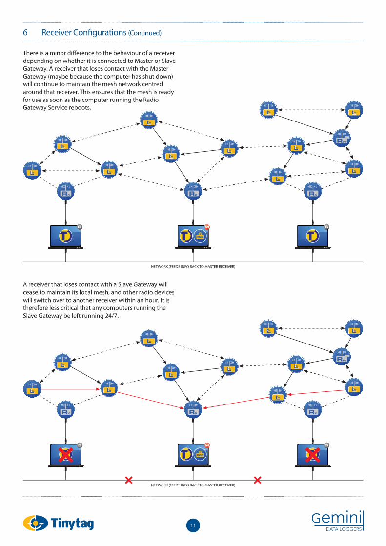
There is a minor diff erence to the behaviour of a receiver depending on whether it is connected to Master or Slave Gateway. A receiver that loses contact with the Master Gateway (maybe because the computer has shut down) will continue to maintain the mesh network centred around that receiver. This ensures that the mesh is ready for use as soon as the computer running the Radio Gateway Service reboots.
A receiver that loses contact with a Slave Gateway will cease to maintain its local mesh, and other radio devices will switch over to another receiver within an hour. It is therefore less critical that any computers running the Slave Gateway be left running 24/7.
NETWORK (FEEDS INFO BACK TO MASTER RECEIVER)
NETWORK (FEEDS INFO BACK TO MASTER RECEIVER)
6 Receiver Confi gurations (Continued)
6.4 Repeater
A receiver which is not connected to any computer will, like every radio device, continue to participate in the mesh network. It can act as a repeater for other devices which have poor contact with other devices in the mesh, or to improve the range of an installation.
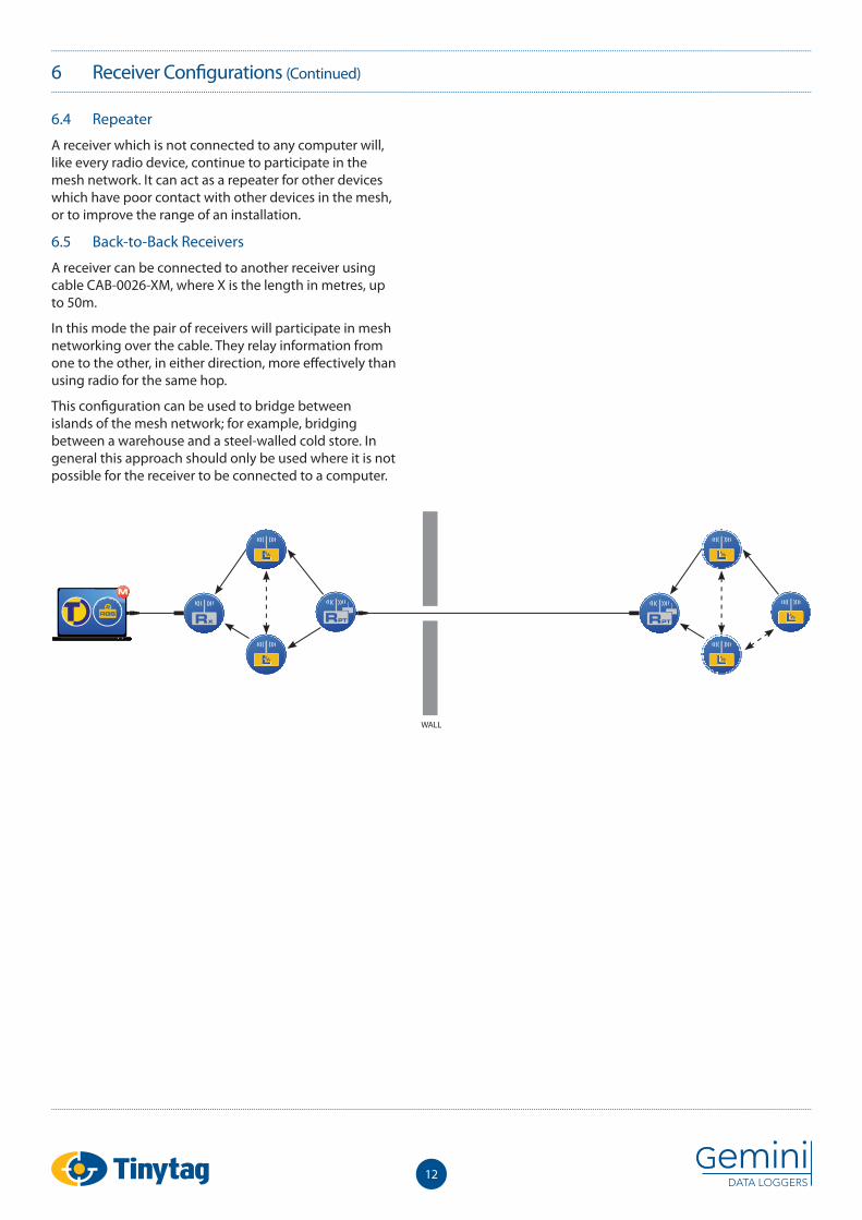
6.5 Back-to-Back Receivers
A receiver can be connected to another receiver using cable CAB-0026-XM, where X is the length in metres, up to 50m.
In this mode the pair of receivers will participate in mesh networking over the cable. They relay information from one to the other, in either direction, more eff ectively than using radio for the same hop.
This confi guration can be used to bridge between islands of the mesh network; for example, bridging between a warehouse and a steel-walled cold store. In general this approach should only be used where it is not possible for the receiver to be connected to a computer.
12
WALL
13
7 Mesh Network Behaviour
7.1 Switching On a Device
When a device is fi rst switched on it will send new measurements downstream as soon as it has any radio contact with another device. If there is a mesh established this should happen within a few minutes.
When the Radio Gateway Service sees the fi rst of these measurements it knows that the new logger exists. At this point it should quickly determine the identity of the logger, and begin collating measurements and requesting retransmissions if any measurements are lost.
7.2 Moving a Device
When a device is moved from one place in the mesh to another it may take between 30 and 60 minutes to work out its new place in the mesh.
This meshing process works on a 30 minute cycle. After being moved the logger may not fully adapt until after one whole cycle.
7.3 Starting the Radio Gateway Service
When the Radio Gateway Service is fi rst started it needs to wait for a packet to arrive from each logger before it knows which loggers are present in the mesh. This is another process which will take up to one logging interval for each logger.
An exception is loggers which had previously established a direct connection to the receiver (that is, not via any mesh repeaters) within the last 4 days. It will probe these loggers immediately to see if they still exist within direct range.
This again assumes that there is a well established mesh; in particular, that the receiver is not just being switched on at the same time.
7.4 Switching On the Receiver
Receivers need to fi nd their place in the mesh exactly like a logger. This adds an extra 30 minutes on to the “Starting the Radio Gateway Service” scenario.
If the Radio Gateway Service is being shut down, possibly over night, it is desirable to avoid this delay by leaving the receiver running. For receivers which rely on external USB power it is possible to leave the receiver powered from USB hub while the computer is switched off . This solution does rely on retaining power for the USB hub.
7.5 Redundant Routing
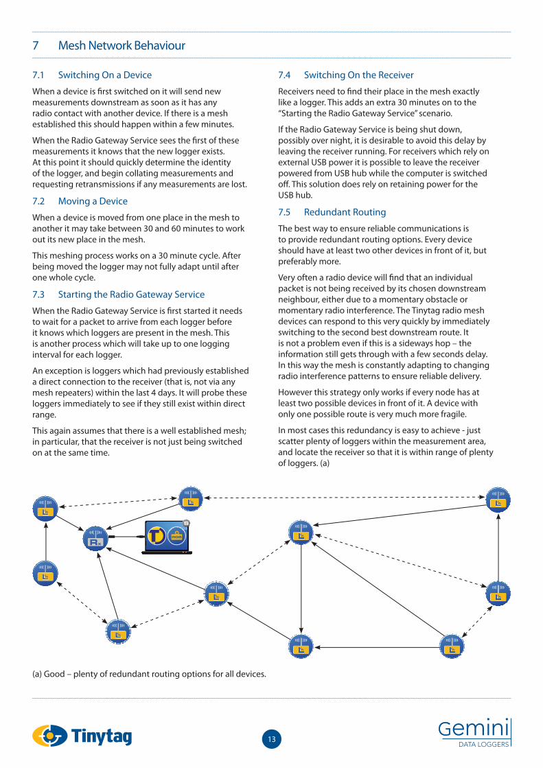
The best way to ensure reliable communications is to provide redundant routing options. Every device should have at least two other devices in front of it, but preferably more.
Very often a radio device will fi nd that an individual packet is not being received by its chosen downstream neighbour, either due to a momentary obstacle or momentary radio interference. The Tinytag radio mesh devices can respond to this very quickly by immediately switching to the second best downstream route. It is not a problem even if this is a sideways hop – the information still gets through with a few seconds delay. In this way the mesh is constantly adapting to changing radio interference patterns to ensure reliable delivery.
However this strategy only works if every node has at least two possible devices in front of it. A device with only one possible route is very much more fragile.
In most cases this redundancy is easy to achieve - just scatter plenty of loggers within the measurement area, and locate the receiver so that it is within range of plenty of loggers. (a)
(a) Good – plenty of redundant routing options for all devices.
7 Mesh Network Behaviour (Continued)
14
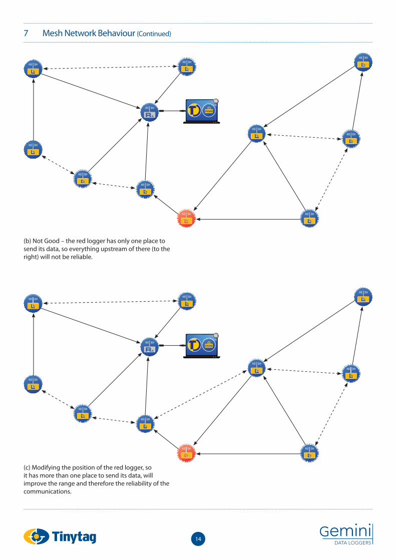
(b) Not Good – the red logger has only one place to send its data, so everything upstream of there (to the right) will not be reliable.
(c) Modifying the position of the red logger, so it has more than one place to send its data, will improve the range and therefore the reliability of the communications.
15
7 Mesh Network Behaviour (Continued)
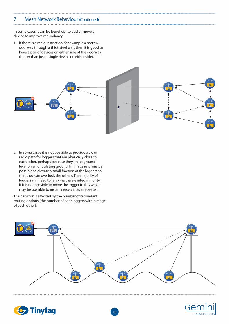
In some cases it can be benefi cial to add or move a device to improve redundancy:
1. If there is a radio restriction, for example a narrow doorway through a thick steel wall, then it is good to have a pair of devices on either side of the doorway (better than just a single device on either side).
2. In some cases it is not possible to provide a clean radio path for loggers that are physically close to each other, perhaps because they are at ground level on an undulating ground. In this case it may be possible to elevate a small fraction of the loggers so that they can overlook the others. The majority of loggers will need to relay via the elevated minority. If it is not possible to move the logger in this way, it may be possible to install a receiver as a repeater.
The network is aff ected by the number of redundant routing options (the number of peer loggers within range of each other):
16
7 Mesh Network Behaviour (Continued)
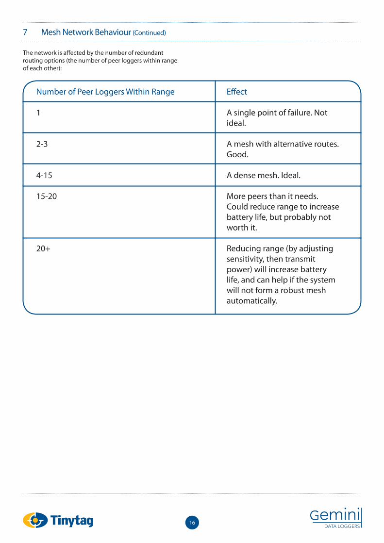
The network is aff ected by the number of redundant routing options (the number of peer loggers within range of each other):
Number of Peer Loggers Within Range
1
2-3
4-15
15-20
20+
Eff ect
A single point of failure. Not ideal.
A mesh with alternative routes. Good.
A dense mesh. Ideal.
More peers than it needs. Could reduce range to increase battery life, but probably not worth it.
Reducing range (by adjusting sensitivity, then transmit power) will increase battery life, and can help if the system will not form a robust mesh automatically.
17
7 Mesh Network Behaviour (Continued)
7.6 Radio Confi guration
7.6.1 Adjusting the Radio Range
This section details how the Radio Range can be adjusted for each logger in the mesh network by changing the values of the parameters in the Radio Confi guration program. Reducing the radio range can be benefi cial when there are 20 or more loggers within range of each other, as this situation can make the mesh network less robust.
In most cases these parameters do not need to be adjusted, and incorrect confi guration may adversely aff ect the performance of your radio network. We therefore advise that you only use this feature following the advice of Tinytag Technical Support.
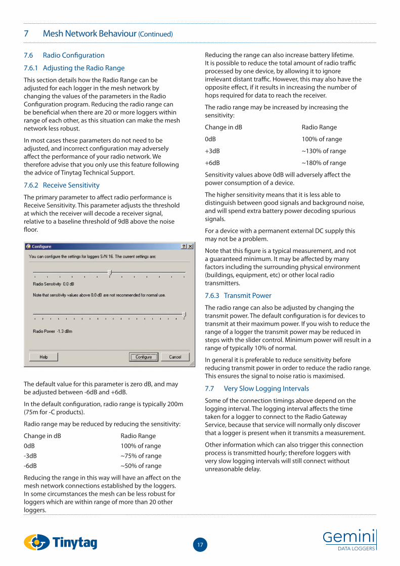
7.6.2 Receive Sensitivity
The primary parameter to aff ect radio performance is Receive Sensitivity. This parameter adjusts the threshold at which the receiver will decode a receiver signal, relative to a baseline threshold of 9dB above the noise fl oor.
The default value for this parameter is zero dB, and may be adjusted between -6dB and +6dB.
In the default confi guration, radio range is typically 200m (75m for -C products).
Radio range may be reduced by reducing the sensitivity:
Change in dB Radio Range0dB 100% of range-3dB ~75% of range-6dB ~50% of range
Reducing the range in this way will have an aff ect on the mesh network connections established by the loggers. In some circumstances the mesh can be less robust for loggers which are within range of more than 20 other loggers.
Reducing the range can also increase battery lifetime. It is possible to reduce the total amount of radio traffi c processed by one device, by allowing it to ignore irrelevant distant traffi c. However, this may also have the opposite eff ect, if it results in increasing the number of hops required for data to reach the receiver.
The radio range may be increased by increasing the sensitivity:
Change in dB Radio Range
0dB 100% of range
+3dB ~130% of range
+6dB ~180% of range
Sensitivity values above 0dB will adversely aff ect the power consumption of a device.
The higher sensitivity means that it is less able to distinguish between good signals and background noise, and will spend extra battery power decoding spurious signals.
For a device with a permanent external DC supply this may not be a problem.
Note that this fi gure is a typical measurement, and not a guaranteed minimum. It may be aff ected by many factors including the surrounding physical environment (buildings, equipment, etc) or other local radio transmitters.
7.6.3 Transmit Power
The radio range can also be adjusted by changing the transmit power. The default confi guration is for devices to transmit at their maximum power. If you wish to reduce the range of a logger the transmit power may be reduced in steps with the slider control. Minimum power will result in a range of typically 10% of normal.
In general it is preferable to reduce sensitivity before reducing transmit power in order to reduce the radio range. This ensures the signal to noise ratio is maximised.
7.7 Very Slow Logging Intervals
Some of the connection timings above depend on the logging interval. The logging interval aff ects the time taken for a logger to connect to the Radio Gateway Service, because that service will normally only discover that a logger is present when it transmits a measurement.
Other information which can also trigger this connection process is transmitted hourly; therefore loggers with very slow logging intervals will still connect without unreasonable delay.
18
7 Mesh Network Behaviour (Continued)
7.8 Very Fast Logging Intervals
Normally loggers will transmit every measurement as it is taken. If the logging interval is faster than 2 minutes then multiple measurements are sent in a burst. This batching process avoids radio congestion, and maximises capacity.
The Replication Timebase Parameter can be changed to adjust the interval between measurement transmissions. A data logger will not transmit measurements more frequently than between one and two multiples of the Replication Timebase.
The default value for this parameter is one minute.
Note that this parameter is diff erent from the Measurement Interval, which can be controlled using Tinytag Explorer and is typically set to 10 minutes. Under normal circumstances, measurements are transmitted as soon as they are taken, and arrive on the computer system almost immediately.
The Replication Timebase Parameter may be increased to save battery power, at the expense of less frequent measurement updates onto the computer system.
For example, if the Measurement Interval is 10 minutes, and the Replication Timebase is 30 minutes, the radio data logger will record between three and six measurements (30 to 60 minutes) before transmitting them all back to the computer system.
This saves battery power due to reduced transmission overheads.
7.9 Data Organisation
Every measurement is written to memory and transmitted downstream as soon as it is taken. Every measurement transmission carries the logger serial number and a measurement sequence number, therefore it is impossible for measurements to be mixed up between devices or recorded in the wrong order.
The Radio Gateway Service uses these sequence numbers to control retransmissions. If the sequence numbers are not consecutive then it requests a retransmission to cover the gap.
If the Radio Gateway Service is aware of a gap when a logger is downloaded into Tinytag Explorer then it will ask the user whether they want to see the data so far, or wait until the gap has been fi lled in.
Data is transferred at approximately 6k per minute.
Data can be transferred from multiple loggers simultaneously. It will prioritise loggers that Tinytag Explorer is waiting for, and loggers that are nearly complete.
If the data gap can not be fi lled in because too much time has passed (approximately two weeks in the default confi guration) and the logger has overwritten its memory then Tinytag Explorer will leave a gap on the graph.
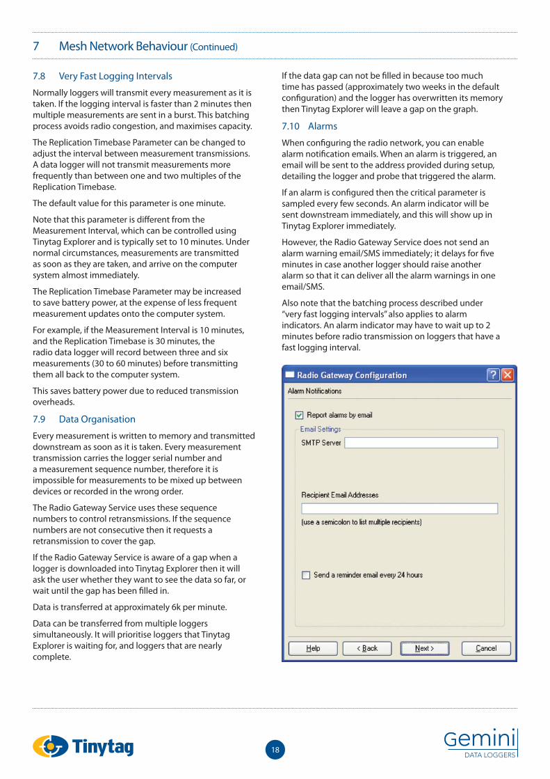
7.10 Alarms
When confi guring the radio network, you can enable alarm notifi cation emails. When an alarm is triggered, an email will be sent to the address provided during setup, detailing the logger and probe that triggered the alarm.
If an alarm is confi gured then the critical parameter is sampled every few seconds. An alarm indicator will be sent downstream immediately, and this will show up in Tinytag Explorer immediately.
However, the Radio Gateway Service does not send an alarm warning email/SMS immediately; it delays for fi ve minutes in case another logger should raise another alarm so that it can deliver all the alarm warnings in one email/SMS.
Also note that the batching process described under “very fast logging intervals” also applies to alarm indicators. An alarm indicator may have to wait up to 2 minutes before radio transmission on loggers that have a fast logging interval.
19
8 Buttons and Lights
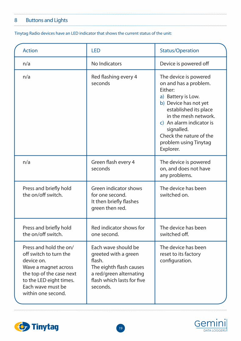
Tinytag Radio devices have an LED indicator that shows the current status of the unit:
Action
n/a
n/a
n/a
Press and briefl y hold the on/off switch.
Press and briefl y hold the on/off switch.
Press and hold the on/off switch to turn the device on.Wave a magnet across the top of the case next to the LED eight times. Each wave must be within one second.
LED
No Indicators
Red fl ashing every 4 seconds
Green fl ash every 4 seconds
Green indicator shows for one second.It then briefl y fl ashes green then red.
Red indicator shows for one second.
Each wave should be greeted with a green fl ash.The eighth fl ash causes a red/green alternating fl ash which lasts for fi ve seconds.
Status/Operation
Device is powered off
The device is powered on and has a problem. Either:a) Battery is Low. b) Device has not yet
established its place in the mesh network.
c) An alarm indicator is signalled.
Check the nature of the problem using Tinytag Explorer.
The device is powered on, and does not have any problems.
The device has been switched on.
The device has been switched off .
The device has been reset to its factory confi guration.
20
9 Rapid Installation
9.1 Introduction
This section describes best practices for installing a system to minimise the time necessary to prove that the mesh network is working as expected.
Note that deviating from this process will not cause any signifi cant problem; at worst it may take an extra hour before all the devices show up.
9.2 Receiver First
The fi rst step in setting up a demonstration system should be placing the receiver. It should be in a location where it will be within range of plenty of the data loggers. An elevated position may help.
Confi gure and start the Radio Gateway Service.
Check using Tinytag Explorer that:
1. Tinytag Explorer has been able to connect to the Gateway Service, and
2. The Gateway Service has been able to connect to the receiver.
This should only take a few seconds. Do all of this before powering up any loggers.
9.3 Nearby Loggers Next
The fi rst loggers to be switched on should be those nearest to the receiver.
These loggers should be within direct range of the receiver, they should connect at full performance within a few minutes.
Do not hold the logger with your hand around the antenna. A logger sends its fi rst transmission within a few seconds of switching on, and this should prompt the Radio Gateway Service to start its connection process. If your hand is around the antenna then this fi rst transmission may be lost. In this case (or if the receiver does not catch this fi rst transmission for some other reason) the Radio Gateway Service will start connecting on the next logging interval.
9.4 Distance Order
Power up the remaining loggers, starting with those closest to the receiver – this order will minimise the time necessary for them all to connect.
In most cases these loggers should establish a preliminary place in the mesh and connect within a few minutes, otherwise the full meshing process will allow them to connect after 30 minutes.
9.5 Don’t Rush It
If one logger is not working it may be tempting to move it a little. Then move it again. Then reboot it. And it is still not working so maybe you move it again.
Then you give up and go for lunch, and fi nd it is working when you return.
It does take time to establish the mesh network, and moving its location may increase the time taken for the meshing to stabilise. Some patience is necessary.
9.6 Transplanting the Network to a New Location
Some additional steps are appropriate if you are moving an entire mesh network system to a new location to minimise your setup time.
Set the logging interval on all loggers to 2 minutes. Fast enough to prompt them to connect quickly, but not so quick that any delay in connecting will cause them to fi ll up their memory with data which would then need to be downloaded.
Clear the logger’s memory. Note that this will erase any readings already taken. This ensures that the Radio Gateway Service will not need to transfer all historic data during the installation at the new location.
21
10 Troubleshooting
10.1 Tinytag Explorer Status Bar Indicator Flashes Red
The connection between Tinytag Explorer and the Radio Gateway Service has been broken. Click on the Status Bar and press the Connect button. This may be either a computer network connection or a software connection within the same computer.
If it cannot connect, then the Radio Gateway Service has a problem. If the Gateway Service is running on a diff erent computer then maybe that computer is turned off . If it is running on the same computer then maybe the service has not started.
Note that this indicator shows Connected as soon as Tinytag Explorer has connected to the Radio Gateway Service. This does not indicate that the Gateway Service has connected to its receiver (via USB) or any loggers (via radio).
10.2 Firewall Confi guration
Tinytag Explorer needs to be able to communicate with the Radio Gateway Server. They connect using TCP and UDP which allows them to run on diff erent computers.
This connection will be under the control of any fi rewall running on these computers.
The Tinytag Explorer installer automatically confi gures the windows fi rewall to allow this connection, so most likely no action is necessary.
Any third party fi rewall will need to be confi gured to permit the following connections:
UDP port 3927: For autodetection
TCP port 3927: For all other communications
22
11 Data Logging
11.1 No stopping
Tinytag radio data loggers will start logging as soon as they are switched on. They do not need to be ‘launched’. It is possible to adjust any confi guration option (logging interval, channels, etc) without stopping the logging process.
11.2 Time zones
Radio data loggers store a timestamp with every measurement. This timestamp is traceable to GMT.
Note that Tinytag Explorer will display this timestamp in your local time zone. This means that timestamps displayed on the graph or readings view will be diff erent for users in diff erent time zones, or will change when users move in and out of daylight savings time.
Timestamps are not aff ected in any way by the time zone of the user who installed or confi gured the data logger.
11.3 Current Readings
Current Readings are updated every few seconds. The update interval will be extended when viewing current readings from multiple devices (or if multiple users are viewing current readings simultaneously). Note that extensive use of this feature may aff ect battery life due to the extra radio activity.
23
12 Other Radio Gateway Functions
12.1 Modbus
The Radio Gateway Service is a windows service which runs 24/7 to collate data from radio loggers.
This data is made available to other software – primarily to Tinytag Explorer, but also to other software through various protocols.
The Radio Gateway Service provides a standard modbus-over-TCP interface, providing read-only access to data logger confi guration and instantaneous measurements (instantaneous measurement means the last received logged measurement).
Modbus may be a convenient option for software which uses Tinytag data loggers as part of an industrial process control or SCADA system.
For more details about Modbus, see Section 13.
12.2 Data Export
Radio Loggers transmit measurements and other information to a single Radio Receiver device using radio. The Receiver relays this information over a USB cable where it is collected by the Radio Gateway Service.
The Radio Gateway Service provides access to historic logged measurements for third party software by downloading CSV fi les over http. There is one CSV fi le per logger. The URLs are listed on the Radio Gateway Server’s pages.
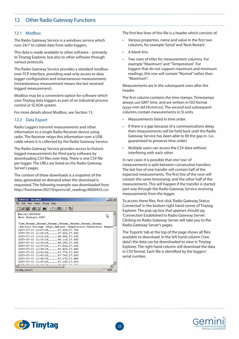
The content of these downloads is a snapshot of the data, generated on demand when the download is requested. The following example was downloaded from http://hostname:3927/Exports/all_readings/8000455.csv
The fi rst few lines of this fi le is a header which consists of:
• Various properties, name and value in the fi rst two columns, for example ‘Serial’ and ‘Next Restart’.
• A blank line.
• Two rows of titles for measurement columns. For example “Maximum” and “Temperature”. For loggers that do not support maximum and minimum readings, this row will contain “Normal” rather than “Maximum”.
Measurements are in the subsequent rows after the header.
The fi rst column contains the time stamps. Timestamps always use GMT time, and are written in ISO format (yyyy-mm-dd hh:mm:ss). The second and subsequent columns contain measurements in SI units.
• Measurements listed in time order.
• If there is a gap because of a communications delay then measurements will be held back until the Radio Gateway Service has been able to fi ll the gap in. (i.e. guaranteed to preserve time order)
• Multiple users can access the CSV data without interfering with each other.
In rare cases it is possible that one ‘row’ of measurements is split between consecutive transfers. The last line of one transfer will contain half of the expected measurements. The fi rst line of the next will contain the same timestamp, and the other half of the measurements. This will happen if the transfer is started part way through the Radio Gateway Service receiving measurements from the logger.
To access these fi les, fi rst click ‘Radio Gateway Status: Connected’ in the bottom right hand corner of Tinytag Explorer. The pop-up box that appears should say ‘Connection Established to Radio Gateway Server’. Clicking on Radio Gateway Server will take you to the Radio Gateway Server’s pages.
The ‘Exports’ tab at the top of the page shows all fi les available to download. In the left hand column (‘raw data’) the data can be downloaded to view in Tinytag Explorer. The right hand column will download the data in CSV format. Each fi le is identifi ed by the loggers’ serial number.
24
12 Other Radio Gateway Functions (Continued)
The CSV fi les linked from the Exports page will always download every measurement, which is ineffi cient and cumbersome for systems which need to keep up to date by tracking new measurements as they arrive. In order to download only new measurements it is necessary for a custom software solution to keep track of the Next Restart value from its previous download, and add this to the URL which is downloaded. For example, the measurements received after the snapshot shown above can be downloaded from http://hostname:3927/Exports/all_readings/8000455.csv?restart=1993
Note that this URL – ending in ?restart=1993 – does not appear anywhere in the Radio Gateway Service web pages. It must be generated by the software solution which wants to perform incremental transfers.
12.3 Proprietary Radio Gateway Service Protocol
The Radio Gateway Service supports a simple text-based proprietary network protocol which provides read-write access to logger confi guration. This is the protocol used by Tinytag Explorer to access the Radio Gateway Service.
25
13 Modbus
13.1 Properties and Registers
The modbus protocol provides read/write access to numbered 16-bit registers. The radio loggers natively use numbered properties which are somewhat similar to modbus registers.
The Radio Gateway Service automatically translates between these two systems. The translation primarily involves changing data types. Modbus registers are always 16-bit integers, while radio logger properties have high-level data types. For example, the logger description is a length limited string. Logging interval is a 32-bit integer.
This property-to-register mapping is generated automatically. Diff erent types of device have diff erent properties; therefore they may have diff erent registers too.
13.2 Devices
The web view in the Radio Gateway Service site includes a Devices tab which contains an index of all devices currently or recently connected to the Radio Gateway Service, with links to a page showing detail for each individual device. Near the top of these device detail pages is a link labelled Modbus Registers which links to a page showing:
• Which logger properties are exposed as Modbus registers
• Which Modbus address is used for each property
• How many Modbus registers are used for each property. For example, 32-bit properties will be spread over two 16-bit registers.
13.3 Expected Values
The Modbus tab on the Radio Gateway Service web view shows the current value of every register on every device.
The Properties tab shows the equivalent in high-level data types.
13.4 Unit Identifi ers
The Modbus protocol supports up to 254 devices, identifi ed by a unit identifi er. Unit identifi ers are automatically assigned to device serial numbers.
The unit identifi er of each device is shown on the Modbus tab page of the Radio Gateway Service web view. These values are stored under the Tinytag Explorer program fi les, in json format, in the fi le:
\Program Files\Tinytag\Tinytag Explorer\var\storage\units.db
It is possible to manually adjust the assignment of unit identifi ers to serial numbers by stopping the Radio Gateway Service, editing this fi le, and restarting.
It is also possible to clear the current assignments by stopping the Radio Gateway Service, deleting this fi le, and restarting. This may be necessary at sites where more than 254 devices have been used and decommissioned, because the unit identifi ers will remain reserved for the decommissioned devices.
13.5 Function Codes
The Radio Gateway Service supports only Modbus function code 0x03: Read Holding Registers.
13.6 32-bit Values
All values wider than 16 bits are mapped onto multiple 16 bit registers.
The request packet for function code 0x03 (Read Holding Registers) includes a byte containing the “quantity of registers” to be read. This is interpreted as the number of 16-bit words which should be transferred.
For example, when requesting the 32-bit value starting at address 50688, this “quantity of registers” byte should contain the value 2. The response will contain the content of two registers: four bytes.
13.7 Freshness
Most registers have a corresponding register containing the number of seconds since the property was refreshed from the device. Some properties are refreshed daily, others are never refreshed. Properties containing ‘current measurements’ are updated every time a measurement is received from the device.
These registers will contain the value 0xFFFF if some error occurred in processing that property. The maximum normal value (for example, if the property was refreshed more than 65535 seconds ago) is 0xFFFE.
13.8 Device Connection
No Modbus interaction is possible until a device is fully connected. That is, when the device leaves the Connecting group in Tinytag Explorer’s Radio Navigator pane, and the device detail page in the Radio Gateway Service site shows its state as HAPPY.
It is not possible to read any registers from a device which is not yet fully connected. The Radio Gateway Service will return an Illegal Data Address error code.
At this point, the Current Readings registers may not yet have been refreshed, and will all contain 0xFFFF. For the fl oating point registers, this corresponds to NaN. These registers will be refreshed when the fi rst measurement is received, at the next logging interval.
26
13 Modbus (Continued)
13.9 Missing Properties
The Radio Gateway Service will return an Illegal Data Address error code if the requested property has not been fetched, or is missing from the device. This should not happen under normal circumstances, but may occur if:
• Requesting a register corresponding to a diagnostic/debugging property, and the Radio Gateway Service is not in a diagnostic mode.
• The device does not contain an expected property. The device’s characteristics are inconsistent with its driver in the Radio Gateway Service. This may happen if using prototype devices, or a pre-release version of the Radio Gateway Service.
• The device detail page can be used to confi rm exactly which properties have been received by the Radio Gateway Service.
13.10 Concurrent Connections
The Radio Gateway Service enforces a limit of no more than 4 concurrent modbus TCP connections.
There is no additional limit to concurrent modbus transactions.
TCP connections are closed after being idle for 10 seconds.
13.11 Modsak
Modsak is a third party modbus diagnostic tool, available at: http://www.wingpath.co.uk/modbus/modsak.php. Gemini Data Loggers is a user of Modsak, but does not endorse or support this product.
The device detail page in the Radio Gateway Service site contains a download link for a Modsak confi guration fi le. When opened, this confi gures Modsak to show most registers from that device, and, when you press the Start button, it continuously polls for new values.
Note that Modsak can not format modbus registers as text strings; therefore these registers are omitted from the download Modsak confi guration line.
Also note that Modsak does not distinguish signed and unsigned values: all numbers are formatted as signed in Modsak, which may or may not be correct.
27
14.1 Batteries
Radio Loggers and Receivers are provided with alkaline batteries unless lithium batteries are requested.
Lithium batteries cannot be provided to overseas customers due to transportation regulations.
Although lithium batteries provide a longer battery life, and increase the temperature measurement range of the logger, replacement batteries are very hard to fi nd and are very expensive. Alkaline batteries are cheap and can be found very easily.
Loggers and Receivers using alkaline batteries require two batteries. Devices using lithium batteries require one battery.
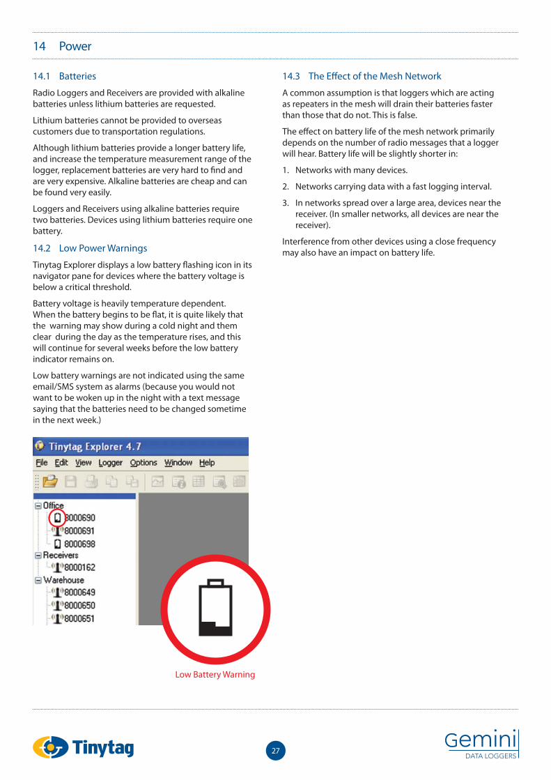
14.2 Low Power Warnings
Tinytag Explorer displays a low battery fl ashing icon in its navigator pane for devices where the battery voltage is below a critical threshold.
Battery voltage is heavily temperature dependent. When the battery begins to be fl at, it is quite likely that the warning may show during a cold night and them clear during the day as the temperature rises, and this will continue for several weeks before the low battery indicator remains on.
Low battery warnings are not indicated using the same email/SMS system as alarms (because you would not want to be woken up in the night with a text message saying that the batteries need to be changed sometime in the next week.)
14.3 The Eff ect of the Mesh Network
A common assumption is that loggers which are acting as repeaters in the mesh will drain their batteries faster than those that do not. This is false.
The eff ect on battery life of the mesh network primarily depends on the number of radio messages that a logger will hear. Battery life will be slightly shorter in:
1. Networks with many devices.
2. Networks carrying data with a fast logging interval.
3. In networks spread over a large area, devices near the receiver. (In smaller networks, all devices are near the receiver).
Interference from other devices using a close frequency may also have an impact on battery life.
14 Power
Low Battery Warning
28
15 Regulatory Compliance
This equipment meets the applicable technical requirements of EN 300 220-1 and EN 300 220-3 for a power Class 7a transmitter & a Class 2 receiver.
It is compliant with the applicable technical EMC requirements of EN 301 489-1 and EN 301 489-3.
It is compliant with the essential requirements of EC Directive 99/5/EC (the R&TTE Directive).
Note for users under FCC authority:
This equipment has been tested and found to comply with the limits for a Class A digital device, pursuant to Part 15 of the FCC Rules. These limits are designed to provide reasonable protection against harmful interference when the equipment is operated in a commercial environment. This equipment generates, uses, and can radiate radio frequency energy and, if not installed and used in accordance with the instruction manual, may cause harmful interference to radio communications. Operation of this equipment in a residential area is likely to cause harmful interference in which case the user will be required to correct the interference at their expense.
Changes or modifi cations not expressly approved by the manufacturer could void the user’s authority to operate the equipment.

29
Notes


Gemini Data Loggers (UK) Ltd.Scientifi c House, Terminus Road,Chichester, West Sussex,PO19 8UJ England.www.tinytag.info
t: +44 (0)1243 813000f: +44 (0)1243 531948e: [email protected]
9800
-003
7: IS
SUE 3
(13T
H JU
LY 2
012)