Timing is a Safety Issue - INCHRON€¦ · Timing is a Safety Issue! ... ISO26262 is defining...
12
Presented on embedded world conference 2011 March 1 st -3 rd in Nuremberg, Germany 1 Timing is a Safety Issue! Functional Safety requires predictable reactions in real-time Dipl.-Ing. Jürgen Belz PROMETO GmbH, Elsener Str. 92-94, 33102 Paderborn, Germany +49 5251 14851-60, [email protected] Dipl.-Ing. Tapio Kramer INCHRON GmbH, Lichtenbergstr. 8, 85748 Garching b. M., Germany +49 89 5484-2960, [email protected] Dr. Ralf Münzenberger INCHRON GmbH, August-Bebel-Str. 88, 14482 Potsdam, Germany +49 331 97992-232, [email protected] Abstract Functional Safety, as defined basically in IEC 61508 and in ISO 26262 for automotive systems, clearly describes actions to take, methods to perform to develop a safe system. Safe means actually the presence of faults and bugs. That implies the detection of malfunctions and taking proper actions, before any harm is done. So it‟s all about timing: Before a hazard occurs, the system has to get itself in time into a safe state involving automated mechanisms and the driver. Precisely defining the safety requirements, including time spans the system has to respond to faults, is mandatory. And it is crucial for project success to evaluate early in the development process if these requirements are met. We will introduce the reader to the timing aspects of functional safety. A model based methodology based on a matured tool suite will be described to help design embedded systems having the correct dynamic behavior and showing robustness to changes and unexpected system states. 1. Motivation During validation the manufacturer of the system has to prove the combined properties and functions of the system comprised of mechanical, electrical and electronic components controlled by software and the user are able to avoid the hazards in time. “Absence of unacceptable risk due to hazards caused by mal-functional behavior of E/E systems”, as stated in the ISO 26262 [1]. Many functional aspects like voltage levels or mechanical robustness are quite static and can be designed with sufficient safety margins. The dynamic behavior and reaction times on the contrary are very dependent on the interactions and interferences with all system components. Predicting and ensuring them to fulfill the timing requirements by design requires a good specification and proper design of the dynamic behavior starting in early design phases.
Transcript of Timing is a Safety Issue - INCHRON€¦ · Timing is a Safety Issue! ... ISO26262 is defining...
Presented on embedded world conference 2011 March 1st-3
rd in Nuremberg, Germany 1
Timing is a Safety Issue! Functional Safety requires predictable reactions in real-time
Dipl.-Ing. Jürgen Belz PROMETO GmbH, Elsener Str. 92-94, 33102 Paderborn, Germany
+49 5251 14851-60, [email protected]
Dipl.-Ing. Tapio Kramer INCHRON GmbH, Lichtenbergstr. 8, 85748 Garching b. M., Germany
+49 89 5484-2960, [email protected]
Dr. Ralf Münzenberger INCHRON GmbH, August-Bebel-Str. 88, 14482 Potsdam, Germany
+49 331 97992-232, [email protected]
Abstract
Functional Safety, as defined basically in IEC 61508 and in ISO 26262 for automotive systems, clearly describes actions to take, methods to perform to develop a safe system. Safe means actually the presence of faults and bugs. That implies the detection of malfunctions and taking proper actions, before any harm is done. So it‟s all about timing: Before a hazard occurs, the system has to get itself in time into a safe state involving automated mechanisms and the driver.
Precisely defining the safety requirements, including time spans the system has to respond to faults, is mandatory. And it is crucial for project success to evaluate early in the development process if these requirements are met. We will introduce the reader to the timing aspects of functional safety. A model based methodology based on a matured tool suite will be described to help design embedded systems having the correct dynamic behavior and showing robustness to changes and unexpected system states.
1. Motivation
During validation the manufacturer of the system has to prove the combined properties and functions of the system comprised of mechanical, electrical and electronic components controlled by software and the user are able to avoid the hazards in time. “Absence of unacceptable risk due to hazards caused by mal-functional behavior of E/E systems”, as stated in the ISO 26262 [1].
Many functional aspects like voltage levels or mechanical robustness are quite static and can be designed with sufficient safety margins. The dynamic behavior and reaction times on the contrary are very dependent on the interactions and interferences with all system components. Predicting and ensuring them to fulfill the timing requirements by design requires a good specification and proper design of the dynamic behavior starting in early design phases.

Presented on embedded world conference 2011 March 1st-3
rd in Nuremberg, Germany 2
Modeling the real-time behavior of embedded systems enables engineering to describe the timing properties and interactions of software and hardware. By simulating and validating the model, the reaction, performance and timing of the system can be analyzed and tested against the timing requirements it has from the functional safety – starting already in early design phases.
How well do the current development projects do? Only one third of all development projects are within the planned functionality, quality, effort and time according to the Standish Group‟s CHAOS Report [2]. Speculating how this maps to automotive E/E systems, one would tend to claim a better quota, but would also have a rather tight and stressful project progress in mind. An orderly project beginning and advance is very often followed by a project final with huge last minute efforts for implementing late requirements and debugging complex errors. In the end the project team made it before the project crashed, but all involved parties had to sacrifice some planned features, time lines, quality measures or profits – causing quite some frustration.
The growing complexity of automotive E/E systems and functional safety requirements demand not only incremental but substantial changes in development methods and processes. There is help. A lot good, proven processes and methods are available. CMMI, automotive SPICE and last but not least ISO26262 not only demand higher quality, they provide proven recipes to address the challenges.
One important factor in succeeding to manage the complexity is how the project is able to handle timing within the E/E system. In the distributed, heterogeneous computer system, what a current automotive E/E system actually is, application functions are performed by multiple microcontrollers and communication busses. Sensor signals are acquired, transformed and transferred as digital data that is processed by software functions. These asynchronous actions have to result in predictable system reactions at a defined time and performance. In the course of this paper the details and implications will be further elaborated.
2. Functional Safety – avoidance of harm
ISO26262 is defining functional safety as absence of unacceptable risks. The design of E/E-Systems includes several measures to achieve this goal. Functional safety means to deal with malfunctioned behavior so that harm is avoided. Among others timing aspects are stated explicitly.
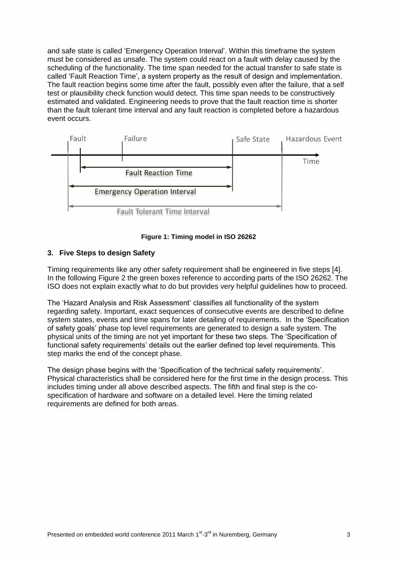
The timing model in ISO 26262 is illustrated in Figure 1. The first spot on the timeline is a fault, which is defined as an event. It could be e.g. a short circuit due to a damaged insulation of a cable. This fault may lead to a failure (2nd spot on the timeline) in that an ECU stops working correctly.
The system must react on any safety critical failure. The most common approach is the transfer to a safe state (3rd spot on the timeline) which mostly means to switch off the system. But in some cases a functionality cannot be abandoned so that a switch-off is not feasible. One example is the breaking system which requires high availability. The ABS functionality may be switched off in case of a failure while the breaks themselves still have to remain fully functional. Nevertheless the transition to a safe state must be completed before a hazardous event occurs (4th spot on the timeline). This is defined as the starting point where harm can occur.
The time span between a fault and the hazardous event is called „Fault Tolerant Time Interval‟ and is used to define the worst case reaction time of the system to be functional safe. Any countermeasure must be finished within this interval. The time span between fault
Presented on embedded world conference 2011 March 1st-3
rd in Nuremberg, Germany 3
and safe state is called „Emergency Operation Interval‟. Within this timeframe the system must be considered as unsafe. The system could react on a fault with delay caused by the scheduling of the functionality. The time span needed for the actual transfer to safe state is called „Fault Reaction Time‟, a system property as the result of design and implementation. The fault reaction begins some time after the fault, possibly even after the failure, that a self test or plausibility check function would detect. This time span needs to be constructively estimated and validated. Engineering needs to prove that the fault reaction time is shorter than the fault tolerant time interval and any fault reaction is completed before a hazardous event occurs.
Figure 1: Timing model in ISO 26262
3. Five Steps to design Safety
Timing requirements like any other safety requirement shall be engineered in five steps [4]. In the following Figure 2 the green boxes reference to according parts of the ISO 26262. The ISO does not explain exactly what to do but provides very helpful guidelines how to proceed.
The „Hazard Analysis and Risk Assessment‟ classifies all functionality of the system regarding safety. Important, exact sequences of consecutive events are described to define system states, events and time spans for later detailing of requirements. In the „Specification of safety goals‟ phase top level requirements are generated to design a safe system. The physical units of the timing are not yet important for these two steps. The „Specification of functional safety requirements‟ details out the earlier defined top level requirements. This step marks the end of the concept phase.
The design phase begins with the „Specification of the technical safety requirements‟. Physical characteristics shall be considered here for the first time in the design process. This includes timing under all above described aspects. The fifth and final step is the co-specification of hardware and software on a detailed level. Here the timing related requirements are defined for both areas.

Presented on embedded world conference 2011 March 1st-3
rd in Nuremberg, Germany 4
Figure 2: Five steps from ISO 26262 to design safety
You may have the impression functional safety is only an engineering issue. The timeframe called safety lifecycle actually starts with a concept phase but ends with decommissioning. There are many activities included on the management side as well as on engineering and production. Among others you have to consider configuration management but also verification tests in production. It is obvious that the engineering of any safety related system is based on architectural decisions that are made before the safety lifecycle starts. The architecture consists of several components that are linked to each other and therefore have to be considered in conjunction. The following abstract will elaborate the safety lifecycle steps using a real world example.
4. Safety design of a memory seat
Memory seats belong to the popular comfort functions in modern vehicle designs. An electric motor adjusts the position of the seat and its backrest. The basic models only have buttons to perform the movement. Advanced models have position controllers with a few presets. High end versions are combined with the personalized remote key of the car. As soon as a person unlocks the car the seat is moving into the position most comfortable for the driver. We have chosen this example because it is easy to understand and does not require deep knowledge in a specific vehicle domain.
The safety lifecycle starts when vehicle development is already running. A specification and the raw system design are at least the preconditions required for the hazard analysis and risk assessment. ISO 26262 requires the definition of the item. In this example the item is defined as the memory seat on the driver‟s side.
3-7 Hazard Analysis and Risk Assessment
The major risk is an unexpected movement while driving. First there is the aspect of shock. Secondly an undersized person may not be able to control the car when the seat moves

Presented on embedded world conference 2011 March 1st-3
rd in Nuremberg, Germany 5
backwards and the driver gets out of reach to the pedals and steering wheel. On the opposite a tall and corpulent person may have difficulties to control the car when the seat is moving too near to the front. All these considerations will be scored in automotive safety integrity levels (ASIL) during the hazard analysis and risk assessment.
3-7 Specification of Safety Goals
Safety goals are the top level safety requirements. “Any unexpected movement of the seat must be detected and immediately stopped” is the safety goal for this example. Whilst „immediately‟ is a definition of a very short time span, there is neither a detailed amount of microseconds, nor a defined start and end of the time span defined in this early phase.
3-8 Specification of Functional Safety Requirements
Safety goals need to be refined. What does “unexpected movement” actually mean? A broken switch is the same as a pressed switch from the system point of view. So, the system cannot differentiate whether the driver or a short circuit causes a movement of the seat. For this case an appropriate functional safety requirement would be: “the driver can interrupt a movement by pressing the switch that leads to a movement in the opposite direction”. In addition we just permit smaller adjustments for the memory seat while driving. Therefore the ECU needs information about vehicle speed to detect driving and has a CAN interface. With his step the concept phase ends.
Figure 3: Fault tree analysis for unexpected moving seat
One main document used in this phase is called fault tree analysis (Figure 3). For our example the failure “seat moves unexpected” has two root causes (either a broken switch or the malfunctioning ECU). Any ECU failure has three possible root causes (power stage, elecronic, software).
4-6 Specification of Technical Safety Requirements
The design phase starts. Physical parameters like timing come into place. A detailled analysis of the kinematics showed that the fault tolerant time interval is 3 seconds long for our memory seat. ISO 26262 reqires to prove there is no violation of this timeframe possible. That leads to time budgets for each hardware and software component. We have to regard also that the memory seat control functionality is integrated into a body computer and not

Presented on embedded world conference 2011 March 1st-3
rd in Nuremberg, Germany 6
running stand alone. Therefore there are running seat tasks as well as other tasks to be concidered in the safety analysis.
5-5 and 5-6 Hardware and Software Engineering
We actually have all information needed:
fault tolerant time interval: 3 seconds
moment of shock: 1 second
time to react (find and press button for opposite movement): 1 second
functionality is integrated on a large body computer
speed and position information is mesured
speed information is received via CAN
switches are connected via digital IO
plausibility checks are performed
We have seen in Figure 1 that there is a time gap between fault (event) and failure (functional reaction). For this example we consider 100 - 300 ms between broken switch and the situation where the ECU interpretes “move”, the failure occurs. This is the time constant of the imput stage of the ECU and is scheduler dependend. We also consider 2.5 s as maximum emergency operation interval.
The memory seat consists of hardware and software components that all have to be considered when designing and calculating the fault reaction:
switches: belong to the user interface. Pressing a switch leads to movement until the seat reaches one of its end positions. Releasing a switch stopps any movement. For this example this switch shall be connected to the digital-input-output stage, even though this is not practice.The I/O ports will be read any 500 µs. Any port with a switch requires filtering which is a up-down counter in the same timeframe.
current sensor: is connected to the analog-digital converter and provides information about the motor current. It is part of the anti-pinch function and requires reading all 400 µs.
speed sensor: is the second part of the anti-pinch function. In principle it counts two pulses per revolution of the motor and is connected to the compare-capture unit of the microcontroller. The assosiated timer will be read all 400 µs
anti-pinch function: is a software that detects entrapment. In this case the seat moves a bit in the opposit direction. The function also runs with 400 µs period and is part of the application. The application does not have dirct access to the hardware. An abstraction is implmented.
CAN: during driving only small corrections of the positions are allowed. Therefore the system requires speed information that is provided every 20 ms. The jitter in the message timing needs to be considered. A message is lost when it is not received within 50 ms.
Power stage: in principle it is an digital output in the IO-layer of the software.
Power drive protection interrupt: in case of a short circuit or open load condition of the power stage an interrupt shall lock the memory seat function.
Memory seat controller: is a state machine that takes care of all actions required. It uses all sensors and messages and drives the power stage.
Presented on embedded world conference 2011 March 1st-3
rd in Nuremberg, Germany 7
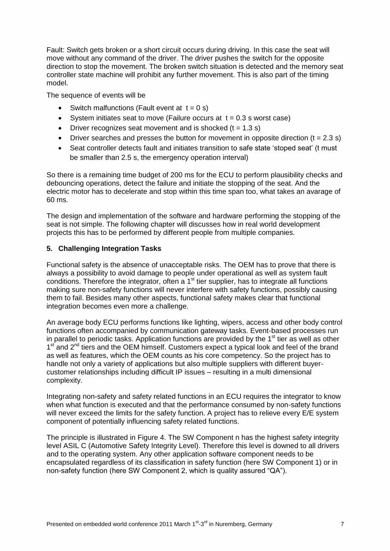
Fault: Switch gets broken or a short circuit occurs during driving. In this case the seat will move without any command of the driver. The driver pushes the switch for the opposite direction to stop the movement. The broken switch situation is detected and the memory seat controller state machine will prohibit any further movement. This is also part of the timing model.
The sequence of events will be
Switch malfunctions (Fault event at t = 0 s)
System initiates seat to move (Failure occurs at t = 0.3 s worst case)
Driver recognizes seat movement and is shocked (t = 1.3 s)
Driver searches and presses the button for movement in opposite direction (t = 2.3 s)
Seat controller detects fault and initiates transition to safe state „stoped seat‟ (t must
be smaller than 2.5 s, the emergency operation interval)
So there is a remaining time budget of 200 ms for the ECU to perform plausibility checks and debouncing operations, detect the failure and initiate the stopping of the seat. And the electric motor has to decelerate and stop within this time span too, what takes an avarage of 60 ms.
The design and implementation of the software and hardware performing the stopping of the seat is not simple. The following chapter will discusses how in real world development projects this has to be performed by different people from multiple companies.
5. Challenging Integration Tasks
Functional safety is the absence of unacceptable risks. The OEM has to prove that there is always a possibility to avoid damage to people under operational as well as system fault conditions. Therefore the integrator, often a 1st tier supplier, has to integrate all functions making sure non-safety functions will never interfere with safety functions, possibly causing them to fail. Besides many other aspects, functional safety makes clear that functional integration becomes even more a challenge.
An average body ECU performs functions like lighting, wipers, access and other body control functions often accompanied by communication gateway tasks. Event-based processes run in parallel to periodic tasks. Application functions are provided by the 1st tier as well as other 1st and 2nd tiers and the OEM himself. Customers expect a typical look and feel of the brand as well as features, which the OEM counts as his core competency. So the project has to handle not only a variety of applications but also multiple suppliers with different buyer-customer relationships including difficult IP issues – resulting in a multi dimensional complexity.
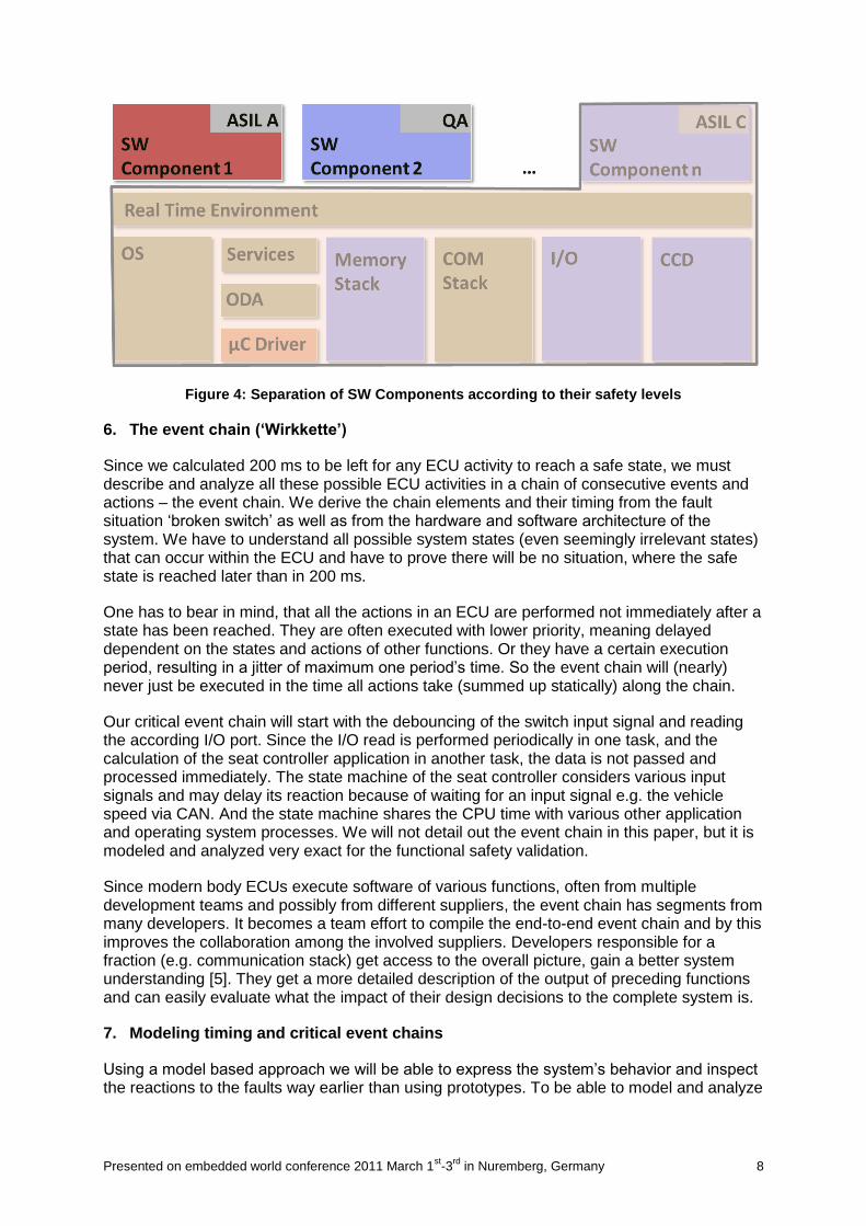
Integrating non-safety and safety related functions in an ECU requires the integrator to know when what function is executed and that the performance consumed by non-safety functions will never exceed the limits for the safety function. A project has to relieve every E/E system component of potentially influencing safety related functions.
The principle is illustrated in Figure 4. The SW Component n has the highest safety integrity level ASIL C (Automotive Safety Integrity Level). Therefore this level is downed to all drivers and to the operating system. Any other application software component needs to be encapsulated regardless of its classification in safety function (here SW Component 1) or in non-safety function (here SW Component 2, which is quality assured “QA”).
Presented on embedded world conference 2011 March 1st-3
rd in Nuremberg, Germany 8
Figure 4: Separation of SW Components according to their safety levels
6. The event chain (‘Wirkkette’)
Since we calculated 200 ms to be left for any ECU activity to reach a safe state, we must describe and analyze all these possible ECU activities in a chain of consecutive events and actions – the event chain. We derive the chain elements and their timing from the fault situation „broken switch‟ as well as from the hardware and software architecture of the system. We have to understand all possible system states (even seemingly irrelevant states) that can occur within the ECU and have to prove there will be no situation, where the safe state is reached later than in 200 ms.
One has to bear in mind, that all the actions in an ECU are performed not immediately after a state has been reached. They are often executed with lower priority, meaning delayed dependent on the states and actions of other functions. Or they have a certain execution period, resulting in a jitter of maximum one period‟s time. So the event chain will (nearly) never just be executed in the time all actions take (summed up statically) along the chain.
Our critical event chain will start with the debouncing of the switch input signal and reading the according I/O port. Since the I/O read is performed periodically in one task, and the calculation of the seat controller application in another task, the data is not passed and processed immediately. The state machine of the seat controller considers various input signals and may delay its reaction because of waiting for an input signal e.g. the vehicle speed via CAN. And the state machine shares the CPU time with various other application and operating system processes. We will not detail out the event chain in this paper, but it is modeled and analyzed very exact for the functional safety validation.
Since modern body ECUs execute software of various functions, often from multiple development teams and possibly from different suppliers, the event chain has segments from many developers. It becomes a team effort to compile the end-to-end event chain and by this improves the collaboration among the involved suppliers. Developers responsible for a fraction (e.g. communication stack) get access to the overall picture, gain a better system understanding [5]. They get a more detailed description of the output of preceding functions and can easily evaluate what the impact of their design decisions to the complete system is.
7. Modeling timing and critical event chains
Using a model based approach we will be able to express the system‟s behavior and inspect the reactions to the faults way earlier than using prototypes. To be able to model and analyze
Presented on embedded world conference 2011 March 1st-3
rd in Nuremberg, Germany 9
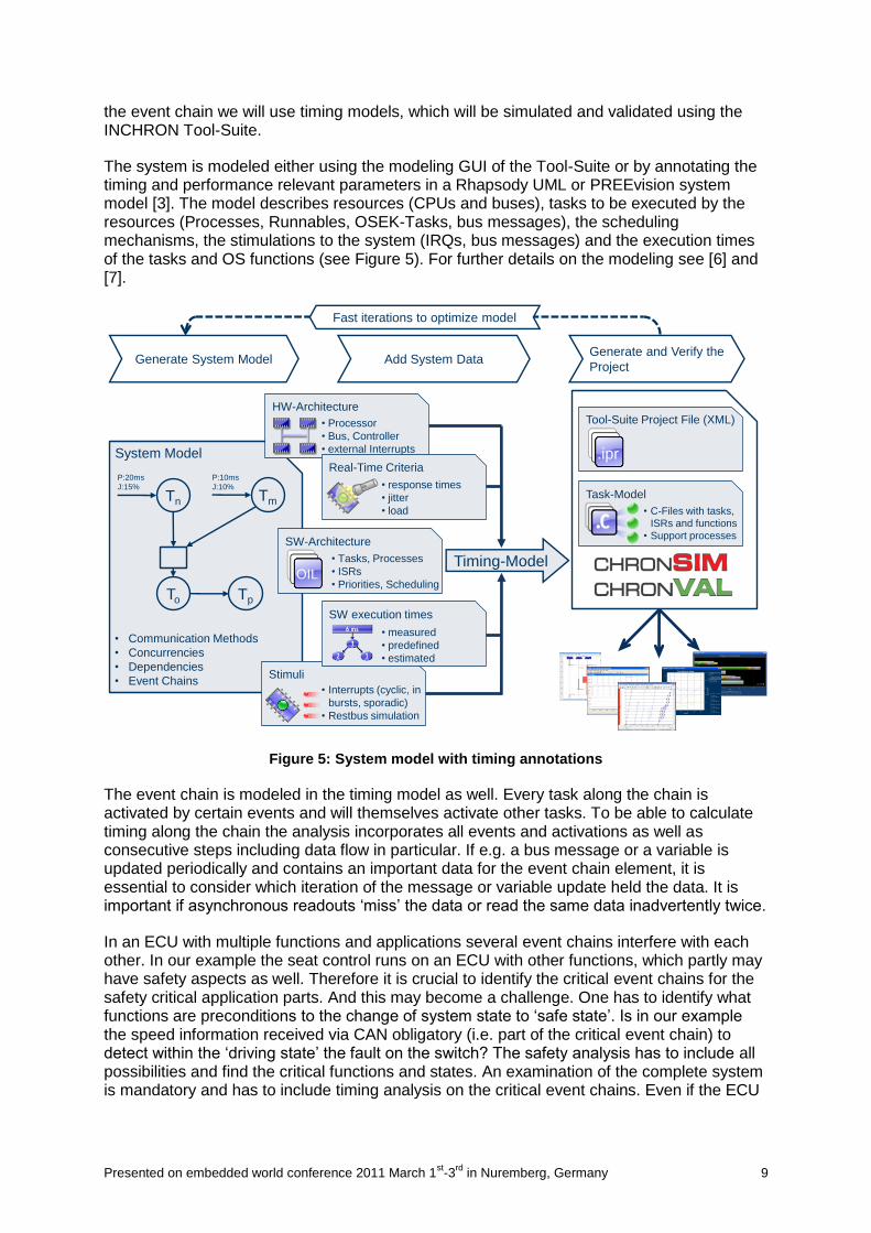
the event chain we will use timing models, which will be simulated and validated using the INCHRON Tool-Suite.
The system is modeled either using the modeling GUI of the Tool-Suite or by annotating the timing and performance relevant parameters in a Rhapsody UML or PREEvision system model [3]. The model describes resources (CPUs and buses), tasks to be executed by the resources (Processes, Runnables, OSEK-Tasks, bus messages), the scheduling mechanisms, the stimulations to the system (IRQs, bus messages) and the execution times of the tasks and OS functions (see Figure 5). For further details on the modeling see [6] and [7].
Figure 5: System model with timing annotations
The event chain is modeled in the timing model as well. Every task along the chain is activated by certain events and will themselves activate other tasks. To be able to calculate timing along the chain the analysis incorporates all events and activations as well as consecutive steps including data flow in particular. If e.g. a bus message or a variable is updated periodically and contains an important data for the event chain element, it is essential to consider which iteration of the message or variable update held the data. It is important if asynchronous readouts „miss‟ the data or read the same data inadvertently twice.
In an ECU with multiple functions and applications several event chains interfere with each other. In our example the seat control runs on an ECU with other functions, which partly may have safety aspects as well. Therefore it is crucial to identify the critical event chains for the safety critical application parts. And this may become a challenge. One has to identify what functions are preconditions to the change of system state to „safe state‟. Is in our example the speed information received via CAN obligatory (i.e. part of the critical event chain) to detect within the „driving state‟ the fault on the switch? The safety analysis has to include all possibilities and find the critical functions and states. An examination of the complete system is mandatory and has to include timing analysis on the critical event chains. Even if the ECU
Generate System Model Add System DataGenerate and Verify the
Project
Tool-Suite Project File (XML)
.ipr
Task-Model
• C-Files with tasks,
ISRs and functions
• Support processes
• Communication Methods
• Concurrencies
• Dependencies
• Event Chains
Tn Tm
To Tp
P:20ms
J:15%
P:10ms
J:10%
System Model
Stimuli
• Interrupts (cyclic, in
bursts, sporadic)
• Restbus simulation
SW execution times
• measured
• predefined
• estimated
HW-Architecture
• Processor
• Bus, Controller
• external Interrupts
Real-Time Criteria
• response times
• jitter
• load
SW-Architecture
• Tasks, Processes
• ISRs
• Priorities, SchedulingOIL
Timing-Model
Fast iterations to optimize model

Presented on embedded world conference 2011 March 1st-3
rd in Nuremberg, Germany 10
is „fast‟ compared to human reactions and mechanic parts – it has to be proven, that it‟s always fast enough.
Figure 6: Asynchronous processing leads to real-time violations
The Figure 6 shows a configuration of functions in principle. If the processing of the function blocks takes place in asynchronous, periodic tasks, drifting clocks with have the effect, that the identical event chain is executed sometimes fast enough, sometimes not. Data misses it‟s periodically receiving function and will wait an iteration to be processed further. Other reasons for Jitter and sometimes even lost data or activations are bursts of interrupts e.g. from bus communication or when higher priority tasks preempt or lower priority tasks block the execution of the critical functions along the event chain. The latter priority inversion may happen when the low priority task is not preemptable or if a semaphore is not released properly in time.
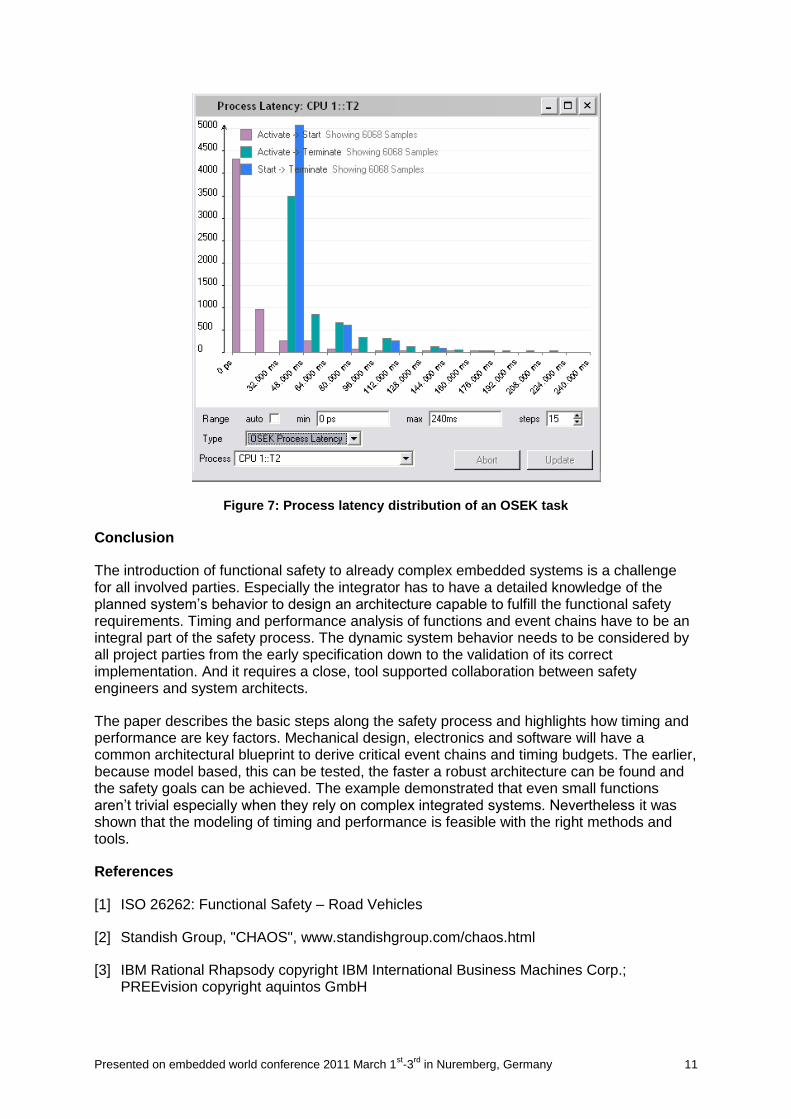
An analysis of task and event chain timing will reveal how the system performs the scheduling of functions and how critical data is processed. A validation finds the best and worst case timings and system reactions. Simulation reveals individual system behavior and allows statistical analysis (Figure 7) as well as understanding the detailed system behavior. The INCHRON Tool-Suite is offers both, simulation and mathematical validation together with a variety of diagrams and reports representing different views on the systems behavior.
Comfort
Functions
Motor-2Switch-2Motion
Control-2
Seat Ctrl.
Logic
Switch-1Motion
Control-1
Fault
DetectionMotor-1
Max. Reaction Time Real-Time
Violation!
Max. Reaction Time
Presented on embedded world conference 2011 March 1st-3
rd in Nuremberg, Germany 11
Figure 7: Process latency distribution of an OSEK task
Conclusion
The introduction of functional safety to already complex embedded systems is a challenge for all involved parties. Especially the integrator has to have a detailed knowledge of the planned system‟s behavior to design an architecture capable to fulfill the functional safety requirements. Timing and performance analysis of functions and event chains have to be an integral part of the safety process. The dynamic system behavior needs to be considered by all project parties from the early specification down to the validation of its correct implementation. And it requires a close, tool supported collaboration between safety engineers and system architects.
The paper describes the basic steps along the safety process and highlights how timing and performance are key factors. Mechanical design, electronics and software will have a common architectural blueprint to derive critical event chains and timing budgets. The earlier, because model based, this can be tested, the faster a robust architecture can be found and the safety goals can be achieved. The example demonstrated that even small functions aren‟t trivial especially when they rely on complex integrated systems. Nevertheless it was shown that the modeling of timing and performance is feasible with the right methods and tools.
References
[1] ISO 26262: Functional Safety – Road Vehicles
[2] Standish Group, "CHAOS", www.standishgroup.com/chaos.html
[3] IBM Rational Rhapsody copyright IBM International Business Machines Corp.; PREEvision copyright aquintos GmbH
Presented on embedded world conference 2011 March 1st-3
rd in Nuremberg, Germany 12
[4] Fernlehrgang ISO 26262; J. Belz, Prof. M. Broy, Dr. G. Glöe, C. Jung, S. Kovacevic, M. Maihöfer, J. Philipps, A. Reuter; www.car-training-institute.com∕iso26262
[5] B. Augustin, Audi AG; Integration of previously independent control units and functions – challenges of a collaboration project; 2. Fachkongress Echtzeitentwicklung 2010; www.echtzeitkongress.de
[6] T. Kramer, R. Münzenberger; New Functions, New Sensors, New Architectures – How to Cope with the Real-Time Requirements; In proceedings of Advanced Microsystems for Automotive Applications 2009, Berlin; www.amaa.de; ISBN 978-3-642-00744-6
[7] A. Wolfram and M. Makarov Continental AG, T.Kramer, W. Ramisch, R. Münzenberger; Design of Robust System Architectures for Automotive ECUs; In proceedings of Conquest 2009, Nuremberg; www.isqi.org/konferenzen/conquest/2009/