


Timing for DAQ - Indico€¦ · Timing for DAQ ISOTDAQ 2019 –Royal Holloway, University of London...
71
Transcript of Timing for DAQ - Indico€¦ · Timing for DAQ ISOTDAQ 2019 –Royal Holloway, University of London...

Timing for DAQISOTDAQ 2019 – Royal Holloway, University of London

Outline
• A bit of Vocabulary
• Timing in the LHC
• Timing for Front End Detectors
• Timing for Trigger & DAQ
• What is a good timing distribution system for LHC detectors?
• Current timing distributions systems
• New Challenges for Timing distribution in HL-LHC
08/04/2019 ISOTDAQ 2019 - RHUL - [email protected] 2

Time
• the indefinite continued progress of existence and events in the past, present and future regarded as a whole (Oxford Dictionary)
• the measured or measurable period during which an action, process or condition exists or continues (Webster’s Collegiate Dictionary)
…and also…• what prevents everything from happening at once (physicist John Wheeler and others)
• a linear continuum of instants (philosopher Adolf Grünbaum)
• a continuum that lacks spatial dimensions (Encyclopaedia Britannica)
• what clocks measure (attr. to physicists Albert Einstein, Donald Ivey, and others)
08/04/2019 ISOTDAQ 2019 - RHUL - [email protected] 3

Clock
…a physical mechanism that counts the passage of time
• Calendar based on Sun, Moon and Stars, Sundials, water clocks
• 1656 Christiaan Huygens: Pendulum
• 1920 Quartz oscillators
• 1950 atomic clocks
• 1967 definition of SI standard 1 sec based on Caesium atom
• Currently: Optical atomic clocks
08/04/2019 ISOTDAQ 2019 - RHUL - [email protected] 4
A strontium-ion optical clock, Nature

Time Standards
Two widely used time standards:
1. GMT/UT - Based on earth rotation• not uniform due to periodic changes and long term drifts• Varies by ~1 sec/year (order < 10-8)
• UT1 - Universal Time (UT1) is a measure of the actual rotation of the earth, independent of observing location. Formerly called Greenwich Mean Time (GMT).
2. TAI/UTC - Based on atomic oscillations (cesium 133)• Currently the closest approximation to a uniform time• Varies ~1 us/year (order < 10-14)
• TAI - International Atomic Time - the primary time standard in the world today. It is the combined input of many clocks around the world
• UTC - Coordinated Universal Time - is the time broadcast by WWW and other services by technologies such as the GPS satellites and Network Time Protocol (NTP).
http://www.cv.nrao.edu/~rfisher/Ephemerides/times.html
08/04/2019 ISOTDAQ 2019 - RHUL - [email protected] 5

Aligning the time standards
• By definition, UTC and TAI have the same rate, but UTC stays close to Mean Solar Time by adding integer numbers of seconds, called leap seconds, from time to time to keep UT1-UTC <0.9 s (today, UTC – TAI = 37 seconds)
• The difference, DUT1 = UT1 - UTC is monitored by the International Earth Rotation Service and published weekly in IERS Bulletin A along with predictions for a number of months into the future.
http://www.leapsecond.com/java/gpsclock.htm
This is a tentative of ‘synchronization’ of UTC versus UT1.Two different clock sources, as precise as they might be, drift one from each other.
08/04/2019 ISOTDAQ 2019 - RHUL - [email protected] 6

Synchronization
• the coordination of events to operate a system in unison
aesthetic consequences
The Sopwith Camel
…or dramatic ones
08/04/2019 ISOTDAQ 2019 - RHUL - [email protected] 7

LHC’s “atomic clock”: the RF
9
RF cavities in LHC (4 modules@point4, Echenevex)
LHCbATLAS
CMS
CMS
08/04/2019 ISOTDAQ 2019 - RHUL - [email protected]
RF= Radio Frequency

Pb ions
protons The Radio Frequency is not fixed:• it is a function of particle type and
energy• It is ramping up at the beginning of each
fill
• it is modulated by beam characteristics and RF parameters
• It is however extremely stable during flat top (ie during collision time).
The LHC RF
10
• The Radio Frequency is not always the same
08/04/2019 ISOTDAQ 2019 - RHUL - [email protected]
400.788860 MHz -> 400.789715 MHz (protons)
400.784216 MHz -> 400.789639 MHz (ions)

Low Levelloops
processor
BeamPhase
(Bunch/RF Phase and Vt/RF Phase)
VCXO400.79MHz
LHC Control RoomBeam
parameter
÷10
÷3564
BeamRadial
Position
40MHz
11kHz
11kHz
400MHz
CavitiesController
Beammonitoring
system
The LHC RF Modulation Scheme (simplified)
1108/04/2019 ISOTDAQ 2019 - RHUL - [email protected]
EXPERIMENTS
Frequency program

LHC RF~400.8MHz
1 2 3 4 5 6 7 8 9 10 11 12 13Buckets
BeamBunch
The Bunch Clock is the frequency at which an observer sitting close to the ring could ‘see’ particles passing
The LHC RF & the Particle Bunches
12
LHC Bunch Clock~40.08MHz
08/04/2019 ISOTDAQ 2019 - RHUL - [email protected]

The LHC Bunch Clock
1308/04/2019 ISOTDAQ 2019 - RHUL - [email protected]
BC frequency ~40.079 MHzOrbit (Revolution Frequency) ~11.2 kHz

The BC: the heart beat of the LHC detectors
In LHC detectors, everything is happening synchronously to the Bunch Clock:
• Collisions
• Signal sampling for Analogue to Digital conversion………………………………………………….
• Event stamping
• Sorting event data (coincidences)
• Trigger generation
• Particles identification• Measuring the time of flight between two points to obtain the velocity
• Combining with momentum information to derive the mass
• Track reconstruction
• Vertex reconstruction (between 20 and 60 piled up events per collision at LHC)
• Event reconstruction
15
Individual need of each front end sensor
System need (Trigger, Event reconstruction)
08/04/2019 ISOTDAQ 2019 - RHUL - [email protected]

The Bunch Clock (40.079MHz) has to be delivered
• EVERYWHERE, • ANYTIME, • and with an excellent STABILITY & QUALITY
The Orbit signal (a.k.a. revolution frequency) (11.24kHz) is also needed
08/04/2019 ISOTDAQ 2019 - RHUL - [email protected] 16

Timing for …Detector front end electronics
Trigger & DAQ
08/04/2019 ISOTDAQ 2019 - RHUL - [email protected] 17

Detector front-ends: single sample
• The sensor signal is usually amplified and shaped
• A comparator generates a digital pulse
• The threshold crossing time is captured and digitized by a TDC
• TDC measures the passing time of the pulse/particle• uses the Bunch Clock as a start event• a high speed clock counts the elapsed time– a multiple of the Bunch Clock
08/04/2019 ISOTDAQ 2019 - RHUL - [email protected] 18
Time to Digital Converter
BC nBC
Detector front-ends: multiple samples
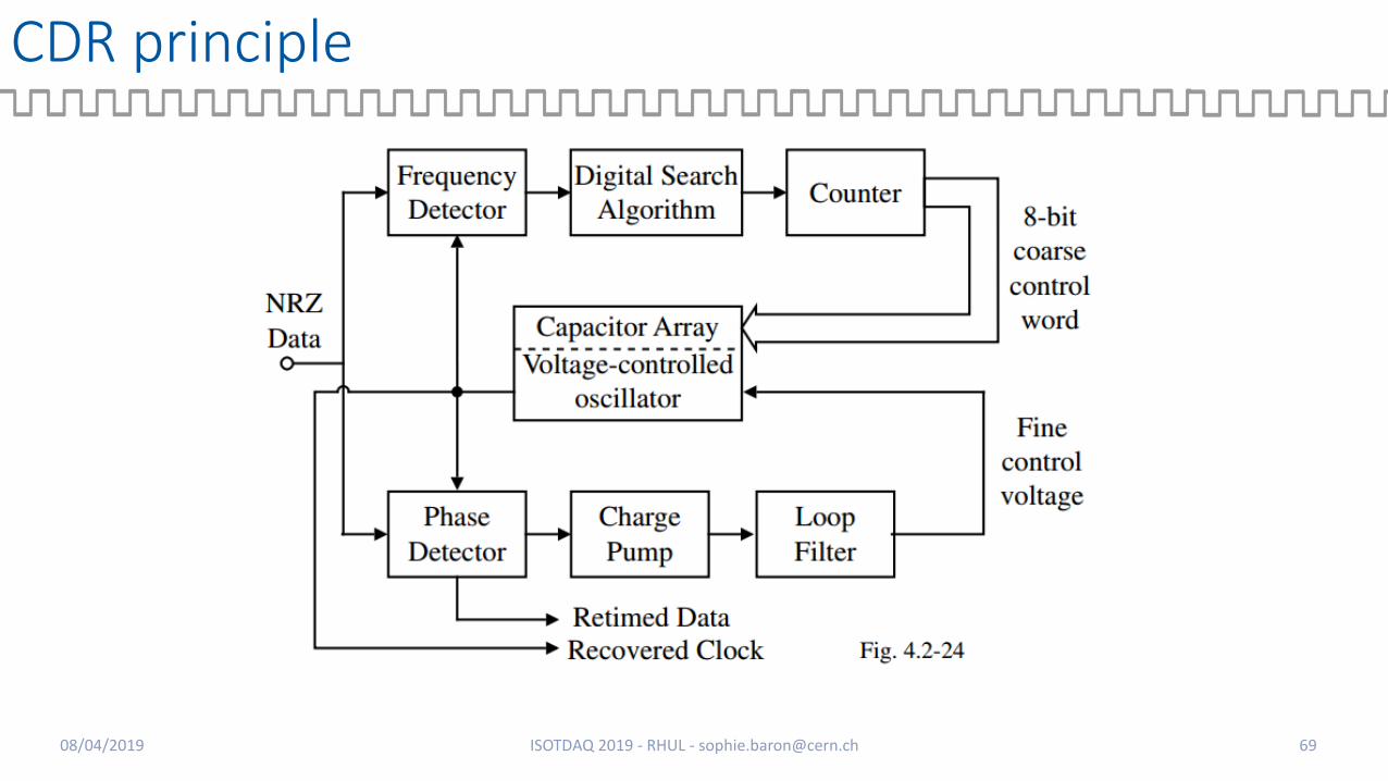
• The sensor signal is usually amplified and shaped
• The full waveform is sampled and digitized at high speed (a multiple of the Bunch Clock) by an ADC
• Information on shape, amplitude, passing time is extracted with DSP algorithms from the digitized waveform samples
08/04/2019 ISOTDAQ 2019 - RHUL - [email protected] 19

Timing Accuracy for Detectors Front-Ends
• Several factors challenge the accuracy of these systems:
• Random noise internal to the front-end electronics
• Signal integrity (substrate noise, etc..)
• Pulse amplitude variations
• Pulse shape variations
• Random & deterministic noise from the clock distribution system• Irregular sampling clock distorts the signal or gives a wrong passing time information
• Multiplying a dirty clock makes things even worse
08/04/2019 ISOTDAQ 2019 - RHUL - [email protected] 20

Timestamping for Trigger & DAQ
2108/04/2019 ISOTDAQ 2019 - RHUL - [email protected]
…crucial for event reconstruction!

Timestamping for Trigger & DAQ
• Every single bunch crossing is timestamped in each Front End module using a local counter incrementing at the collision rate (BC – 40.079MHz)
• This counter is usually reset at every turn by Orbit/Revolution frequency (11.24kHz) , which is every 3564 BC periods
• Note that all the timestamps don’t necessarily carry a collision (bunch structure) … but that each bunch crossing carries up to 60 collisions (pile up)
08/04/2019 ISOTDAQ 2019 - RHUL - [email protected] 22

Timing distribution …
• Timing distribution systems in LHC experiments are in charge of
• Distributing the Bunch Clock signal to each node of the detectors• With accurate and stable frequency – for accurate signal shaping
• With a fixed phase with respect to the beam/collisions – for proper timestamping
• Broadcasting time critical signals to each node of the detectors• Orbit
• Trigger
• And some other time critical signals
…with a low, fixed and deterministic latency
08/04/2019 ISOTDAQ 2019 - RHUL - [email protected] 23

What is a good timing distribution?Distribution systems ..
Assessing distribution quality …
Good clock for …
08/04/2019 ISOTDAQ 2019 - RHUL - [email protected] 24

The LHC Timing Distribution System
Master Clock
Slave Clock
Slave Clock
Slave Clock
Slave Clock
Slave Clock
Slave Clock
Slave Clock
Slave Clock
Slave Clock
Slave Clock
Slave Clock
Slave Clock
Slave Clock
Slave Clock
LHC RF
DETECTORSMAIN CLOCK(4)
SUB DETECTORSMAIN CLOCK(~10/detector)
FRONT-ENDMODULESCLOCKS (o(10k)/detector)
CHALLENGE:100k slaves fully
Synchronized in frequency AND in phase
08/04/2019 ISOTDAQ 2019 - RHUL - [email protected] 25

The LHC Timing Distribution System
Master Clock
Slave Clock
Slave Clock
Slave Clock
Slave Clock
Slave Clock
Slave Clock
Slave Clock
Slave Clock
Slave Clock
Slave Clock
Slave Clock
Slave Clock
Slave Clock
Slave Clock
LHC RF
DETECTORSMAIN CLOCK(4)
SUB DETECTORSMAIN CLOCK(~10/detector)
FRONT-ENDMODULESCLOCKS (o(10k)/detector)
08/04/2019 ISOTDAQ 2019 - RHUL - [email protected] 26

Timing Distribution System in a detector
DETECTORMAIN CLOCK
PARTITIONMAIN CLOCK(~10/detector)
FRONT-ENDMODULESCLOCKS (o(10k)/detector)
Master Clock
Slave Clock
Slave Clock
Slave Clock
Slave Clock
Slave Clock
Slave Clock
08/04/2019 ISOTDAQ 2019 - RHUL - [email protected] 27
Sister clocks

Timing Distribution System in a detector
Master Clock
Slave Clock
Slave Clock
Slave Clock
Slave Clock
Slave Clock
Slave Clock
DETECTORMAIN CLOCK
PARTITIONMAIN CLOCK(~10/detector)
FRONT-ENDMODULESCLOCKS (o(10k)/detector)
ABSOLUTESENSOR CLOCKSTABILITY
OR
BIT
, TR
IGG
ER L
ATEN
CY,
FR
EQU
ENC
Y &
PH
ASE
STA
BIL
ITY
CHANNEL to CHANNELPHASE STABILITY
PARTITION to PARTITIONPHASE STABILITY
08/04/2019 ISOTDAQ 2019 - RHUL - [email protected] 28

Jitter & Phase Noise
How to assess the quality of a clock?• Jitter (in the time domain)• Phase Noise (in the frequency domain)
08/04/2019 ISOTDAQ 2019 - RHUL - [email protected] 29

Jitter
• Time domain measurement
• Various Jitter types (Cycle-to-cycle, period, ..)
• TIE jitter (Time Interval Error or accumulated/phase Jitter):• Actual deviation from the ideal clock period over all clock periods
• The « Ideal Clock » can be an absolutely perfect reference, the master of a distribution system or a sister clock (skew jitter)
• Measured with real time oscilloscopes• Histogramming its Probability Density Function gives interesting information on jitter
sources. • Spectrally rich type of jitter
S(n-1)=T(n-1)-T0(n-1)
S(n)=T(n)-T0(n)
S(n+1)=T(n+1)-T0(n+1)
S(n+2)=T(n+2)-T0(n+2)
σ= std deviation = rms jitter
pkpk jitter
Random jitter:Gaussian shape
DeterministicJitter
08/04/2019 ISOTDAQ 2019 - RHUL - [email protected] 30

Phase Noise
𝑎𝑑𝑖𝑔𝑖𝑡𝑎𝑙 𝑡 = 𝐴 sin 2π𝑓𝑐 𝑡 + 𝜑(𝑡)
𝑎𝑖𝑑𝑒𝑎𝑙 𝑡 = 𝐴 sin(2π𝑓𝑐𝑡)
𝑎𝑟𝑒𝑎𝑙 𝑡 = 𝐴(1 + 𝛼(𝑡)) sin(2π𝑓𝑐 𝑡 + 𝜑(𝑡)
Foffset = Offset Frequency from the signal carrier frequencyPhase Noise=
Spectral power density at foffsettotal power of the carrier signal
08/04/2019 ISOTDAQ 2019 - RHUL - [email protected] 31

Frequency & Time Domains relationship
𝜎 =1
2𝜋𝑓𝑐√න
𝐹1
𝐹2
𝑆𝜑 𝑓 𝑑𝑓
[dBc/Hz]
TIE jitter (rms) is close to
[F1;F2] = integration range
08/04/2019 ISOTDAQ 2019 - RHUL - [email protected] 32
= Phase Noise & Jitter relationship

Phase Noise interpretation
Clock generatorCrystal Oscillator
Wander Jitter
08/04/2019 ISOTDAQ 2019 - RHUL - [email protected] 33
Phase Noise extracted jitter (ps rms)
Clock generator
Crystal Oscillator
Integrated over 1Hz-10Hz (wander) 1.78 ps rms 30.5 ps rms
Integrated over 10Hz-1MHz 2.39 ps rms 0.97 ps rms
Integrated over full range 2.98 ps rms 30.5 ps rms

A good clock for individual sensors…
• Sensors are very sensitive to timing errors as they directly convert into sampling errors
• Unregular sampling edges can distort of the shape of digitized pulses.
=> remove the high frequency jitter
…use PLLs – Phase Lock Loops
08/04/2019 ISOTDAQ 2019 - RHUL - [email protected] 34

A good clock for a (sub) detector/system…
• Track, virtex or event reconstruction• 1000s of Bunch Clock destinations spread all over the
detectors• Beware of sister clocks drifting one from each other
• stable phase between Bunch Clock and Beam
Reduce WANDER due to environment variations
• limit temperature variations• measure and compensate propagation time
08/04/2019 ISOTDAQ 2019 - RHUL - [email protected] 35

Orders of Magnitude for LHC experiments
*A posteriori requirements for LHC detectors. Specific run conditions of 2017-2018 were challenging these values.
(1): the Bunch Clock at the RF is close to a perfect clock <1ps rms
(2): maximum channel-to-channel skew jitter between 2 nodes in the detector
TIEBC ≈ 50 ps rms(1)*TIECh-Ch≈ 1 ns rms(2)*
08/04/2019 ISOTDAQ 2019 - RHUL - [email protected] 36

Current clock distribution systems for LHC experimentsMethods
Legacy systems – RF Backbone, TTC
Systems for LS2 – GBT, TTC-PON
08/04/2019 ISOTDAQ 2019 - RHUL - [email protected] 37

Synchronization methods
• Source synchronous systems• a copy of the clock is sent along with the
data (trigger for example)
• The output of the forwarded clock is adjusted so that the clock transitions in the middle of the data cell. (clock domain crossing)
+-
Clock goes straight and is really clean
2 links, data/clock retiming at Rx
08/04/2019 ISOTDAQ 2019 - RHUL - [email protected] 38
Data
Clock

Synchronization methods
• Self-synchronous systems• the data stream contains both the data
and the clock.
+-
No retiming at Rx, 1 link
Clock recovery not simple at Rx
08/04/2019 ISOTDAQ 2019 - RHUL - [email protected] 39
Data
(the Clock is embedded in the data transitions)

Self synchronous systems
Data Layer Data LayerPhysical Layer
DATA
SEREncoder TX RX DES
DATA
Decoder
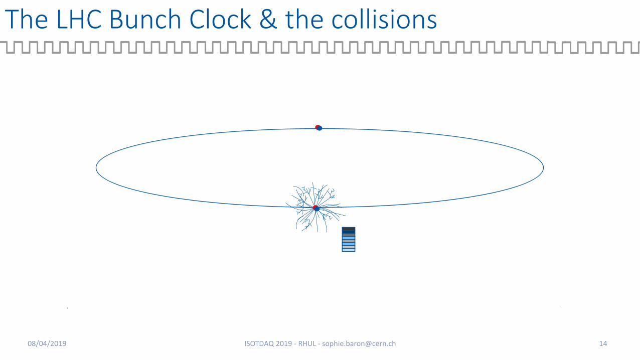
• Physical Interface (LVDS, CML..)• Modulation Schemes (NRZ, PAM4 …)• Clock and Data Recovery (CDR)• Signal Integrity Considerations, • Pre-Emphasis, Equalization
• Encoding/Scrambling• Frame Alignment• Comma Detection• Error Correction schemes• Clock Domain Crossing
Tx Rx
08/04/2019 ISOTDAQ 2019 - RHUL - [email protected] 40

Self synchronous systems
Phase Locked Loops & Clock and Data Recovery…THE keys of self-synchronous systems
08/04/2019 ISOTDAQ 2019 - RHUL - [email protected] 41
(aka PLL) (aka CDR)

From the LHC-RF to the experiments
• The “RF Backbone”
• Source synchronous for a purer clock quality & compatibility with RF needs
P4P5
P8
P2 CCR
• 2 Bunch Clocks (beam 1 & 2)• 2 Orbit signals (beam 1 & 2) = ‘data’
…sent over 4 parallel optical fibers10 km
4 km
5 km
• Excellent BC quality at Rx (~2ps rms)• Huge wander (up to 8ns seasonal drift)
• Phase adjusted wrt beam at experiments• Orbits need to be resynchronized at Rx
CMS
ATLAS
ALICE
LHCb
08/04/2019 ISOTDAQ 2019 - RHUL - [email protected] 42

And in the experiments…mostly self-synchronous
08/04/2019 ISOTDAQ 2019 - RHUL - [email protected] 43
…so far
Self Synchronous systems:Clock and data are embedded in a serial stream
Some examples …

TTC
• 1997-2007• Self Synchronous• Optical, Unidirectional• Carrier Clock: LHC BC
(40.079MHz)• Data:
• Fixed latency:• level-1 trigger
• Low latency• Orbit• bunch and event
numbers• test signals
• broadcast commands• Receiver in radiation area
• Specific ASICs for CDR• TTCrx• QPLL08/04/2019 ISOTDAQ 2019 - RHUL - [email protected] 44
Timing Trigger & Control

TTC
• Physical layer:• Time Domain Multiplexing of A & B channels• Bi-phase Mark encoding• 160Mbps line rate
• Data Layer - Protocol:• A Channel (40Mbps):
• Broadcasting ONLY L1a Trigger (1 bit signal)• Low & fixed latency (1 bit per BC period)• Not protected
• B Channel• Framed & formatted commands and data • Redundancy for error correction & detection• Hamming code (1 bit error correction, 2 bits error detection)
+ Good Clock jitter ~ 10 ps rms- Narrow locking range (sometimes unlocks during ramp)- Strong wander due to temperature variations- Jitter sensitive to data payload
08/04/2019 ISOTDAQ 2019 - RHUL - [email protected] 45
TDM Encoder
40MHz Clock
Channel B (data)
Channel A (trigger)
A B A B A B A B A B
1 0 0 1
1 1 0 0
BPM Encoder
1=0=

GBT & TTC-PON (commissioning LS2)
TTC-PON
GBT
08/04/2019 ISOTDAQ 2019 - RHUL - [email protected] 46
2.4Gbps 9.6Gbps
4.8Gbps 4.8Gbps
Replacing TTC

GBT & TTC-PON (commissioning LS2)
TTC-PON
GBT
08/04/2019 ISOTDAQ 2019 - RHUL - [email protected] 47
2.4Gbps 9.6Gbps
4.8Gbps 4.8Gbps
Replacing TTC

TTC-PON
• PON: Passive Optical Network• FTTH: Fiber To The Home• Single fiber
08/04/2019 ISOTDAQ 2019 - RHUL - [email protected] 48

TTC-PON
• PON: Passive Optical Network• FTTH: Fiber To The Home• Single fiber• 2 directions• 2 wavelengths (1/direction)• Downstream direction (OLTONUs)
• High bandwidth (9.6Gbps)• Self-synchronous
08/04/2019 ISOTDAQ 2019 - RHUL - [email protected] 49

TTC-PON
• Upstream direction(ONUsOLT)• 2.4Gbps• TDMA, round robin• Shared bandwidth• Synchronized to Bunch Clock
• PON: Passive Optical Network• FTTH: Fiber To The Home• Single fiber• 2 directions• 2 wavelengths (1/direction)• Downstream direction (OLTONUs)
• High bandwidth (9.6Gbps)• Self-synchronous
08/04/2019 ISOTDAQ 2019 - RHUL - [email protected] 50
Fullycustomizedprotocols

TTC-PON
• Deliverables:• XG-PON optical modules (COTS)
• Python based control software • Control field reserved in the PON frame
• Sophisticated VHDL IP blocks• Implementing PON protocol and system calibration/monitoring tools
• Providing fixed and deterministic phase and latency• Both for clock and data
• Interfacing easily to GBT
• Hardware reference design• Using the Si5344/45 PLL family to clean recovered clock out of the FPGA
• Extremely good and fixed phase!
+ Super low clock jitter ~ 2 ps rms+ Insensitive to payload+ limited wander / to temperature variation
08/04/2019 ISOTDAQ 2019 - RHUL - [email protected] 51

GBT & TTC-PON (commissioning LS2)
TTC-PON
GBT
2.4Gbps 9.6Gbps
4.8Gbps 4.8Gbps
08/04/2019 ISOTDAQ 2019 - RHUL - [email protected] 52

GBT
Chipset produced in 2015-2017
• Self-synchronous• 4.48 Gb/s optical links, synchronized to Bunch Clock• Timing and Trigger downstream, Data Acquisition (DAQ) upstream + Slow Control • Point-to-point, optical, bidirectional (two fibres), constant latency
• Back-end: HDL IP core implementing specific GBT protocol (GBT-FPGA)• Front-end: custom designed Rad-hard chipset (GBTx, GBT-SCA, LpGBT, GBTIA…) – 50 MRad
08/04/2019 ISOTDAQ 2019 - RHUL - [email protected] 53
DAQ
TIMING & TRIGGER
Versatile link

GBT
• GBT protocol• Strong Forward Error Correction (FEC)
• 32 bits of redundancy for 84 bits of payload data (total of 120 bits per frame @ 40.079MHz)
• Correction of up to 16 wrong consecutive bits
• 3.32 Gb/s user payload downstream
• FEC can be disabled upstream to increase bandwidth (widebus mode)
• Fixed and Low latency• Clock & data recovered at fixed phase/latency
• Very specific requirement
• Not common in commercial world
08/04/2019 ISOTDAQ 2019 - RHUL - [email protected] 54
BC (40 MHz)
GBT protocol - 4.8 Gbps
+ Clock jitter ~ 15 ps rms+ independent from payload+ limited wander / temperature variation
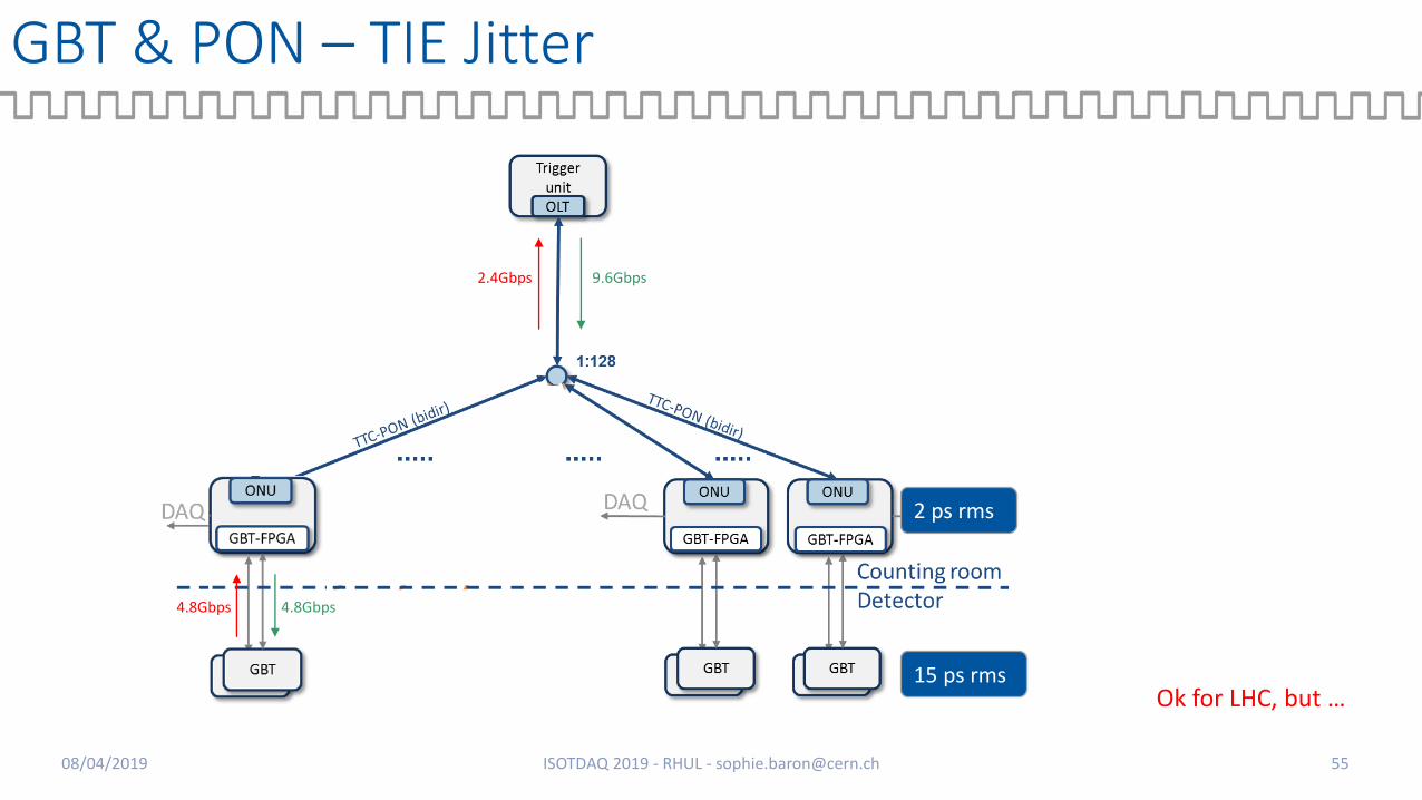
GBT & PON – TIE Jitter
2 ps rms
15 ps rms
2.4Gbps 9.6Gbps
4.8Gbps 4.8Gbps
08/04/2019 ISOTDAQ 2019 - RHUL - [email protected] 55
Ok for LHC, but …

New needs for HL-LHC
Ultimate HL-LHC luminosity target is now 7.5x1034 Hz/cm2 = 200 Pile Up events
CMS 200PU HL-LHC Event:
Courtesy Lindsey Gray, FNAL
08/04/2019 ISOTDAQ 2019 - RHUL - [email protected] 57

High Precision Timing to fight Pile Up
• High Precision Timing allows time separation of Interaction vertices
Courtesy Lindsey Gray, FNAL
08/04/2019 ISOTDAQ 2019 - RHUL - [email protected] 58

Get prepared for new requirements…
LHC
Initial needs
• TIEBC ≈ 50 ps rms
• TIECh-Ch≈ 1 ns rms
HL-LHC
requirements
• TIEBC ≈ 10 ps rms
• TIECh-Ch≈ 30 ps rms
• And more radiations…
• And more bandwidth…
(and more troubles)
08/04/2019 ISOTDAQ 2019 - RHUL - [email protected] 59

Backbone…towards a new paradigm: white Rabbit
• Don’t distribute the Bunch Clock itself anymore…
• But distribute • The information to reconstruct it at each end node
• Frequency and phase variation
• With a fixed & controlled latency
08/04/2019 ISOTDAQ 2019 - RHUL - [email protected] 60

Backbone…towards a new paradigm
• Innovative concept• Self synchronous Standard Ethernet network• Future part of PTP standard
• IEEE1588-2018 (High Accuracy)
• High accuracy synchronisation to the GPS time• Precise GPS distribution• Precise round trip measurement &
compensation• Wander ~0, even over 10km
• Bounded and low-latency Control Data
+ specific hardware modules to recreate the Bunch clock
08/04/2019 ISOTDAQ 2019 - RHUL - [email protected] 61
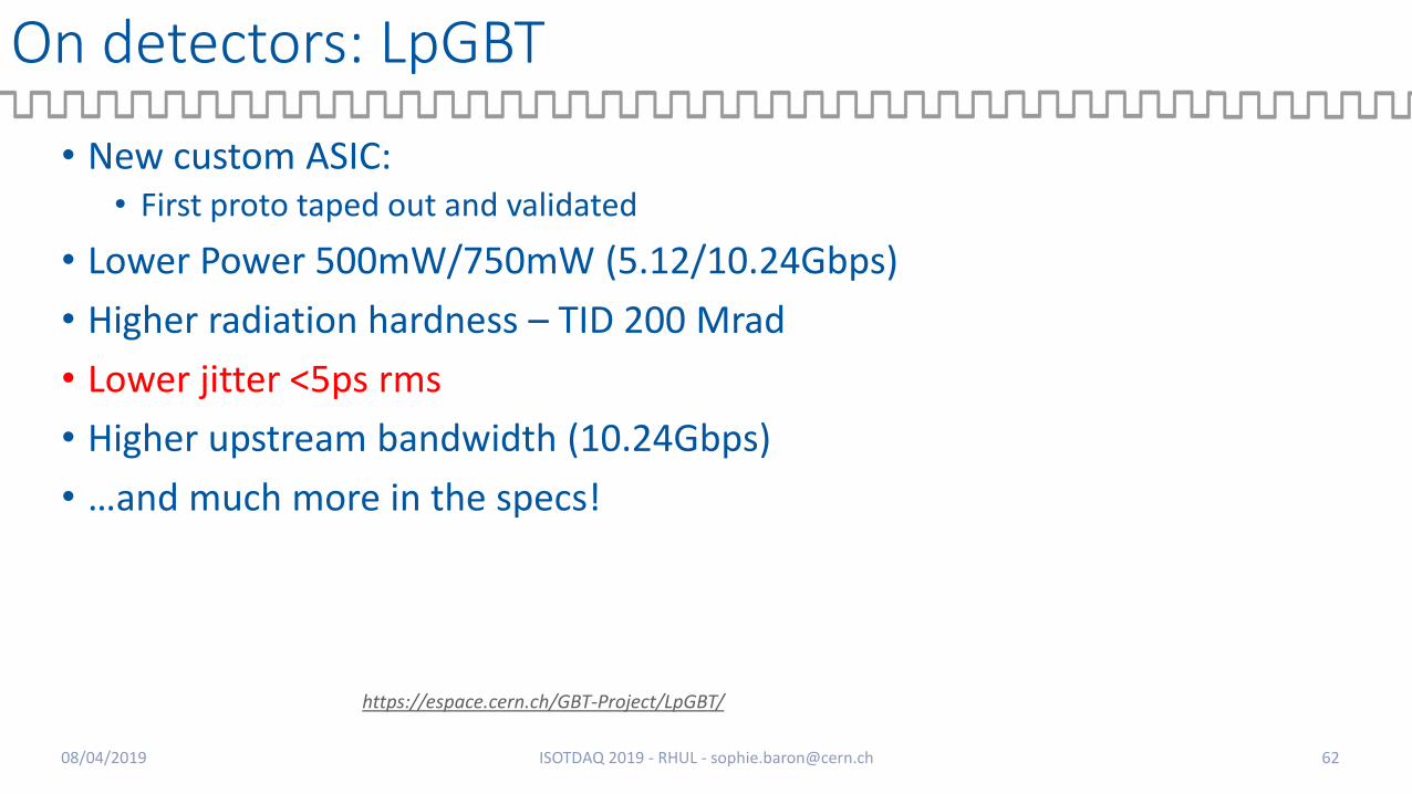
On detectors: LpGBT
• New custom ASIC: • First proto taped out and validated
• Lower Power 500mW/750mW (5.12/10.24Gbps)
• Higher radiation hardness – TID 200 Mrad
• Lower jitter <5ps rms
• Higher upstream bandwidth (10.24Gbps)
• …and much more in the specs!
https://espace.cern.ch/GBT-Project/LpGBT/
08/04/2019 ISOTDAQ 2019 - RHUL - [email protected] 62

…and High Precision Timing
08/04/2019 ISOTDAQ 2019 - RHUL - [email protected] 63
Self-synchronous? Source Synchronous?
Ensuring low jitter and low wander between master-slave and slave-slave is a challenge for each layer• Extreme care on link design• Precise round trip measurement and/or compensation
All experiments are collaborating on this challenging topic…

08/04/2019 ISOTDAQ 2019 - RHUL - [email protected] 64
https://espace.cern.ch/HighPrecisionTiming
Join our interest group if you want to know more About the challenges we are facing!

Phase Noise measurement
08/04/2019 ISOTDAQ 2019 - RHUL - [email protected] 67
E5052B SSA Signal Source Analyzer

PLL principle
08/04/2019 ISOTDAQ 2019 - RHUL - [email protected] 68
https://www.electronics-notes.com/articles/radio/pll-phase-locked-loop/tutorial-primer-basics.php

Bunch Clock over White Rabbit
• Phase and frequency information of the RF/Bunch Clock could be transmitted with a fixed propagation time guaranteed by the White Rabbit Network allowing to reconstruct the RF/Bunch clock at the node
• If the DDS synthesizer is precise enough, the reconstructed RF/Bunch Clock could potentially benefit from the best of bothworlds:• Excellent quality• Fixed phase wrt the RF/BC source
=> Requires specific and careful design, handled by the White Rabbit Team
Distributed Direct Digital Synthesis
08/04/2019 ISOTDAQ 2019 - RHUL - [email protected] 71