Time is money - EAS change...
68
www.EASchangesystems.com Quick die change solutions Time is money UK
Transcript of Time is money - EAS change...

www.EASchangesystems.com
Quick die change solutions
Time is money
UK

IDEAS EASCOME FROM
Your benefits
Complete QDC, SMED and JIT solut ions from one global source.
EAS Quick Die & Quick Mold Change systems reduce manufacturing cost. Quick Die & Mold Change systems (QDC & QMC) lower YOUR manufacturing cost by reducing the change over time, the unproductive time of your presses. Frequent die changes allow inventory to be reduced and give faster response to customer requirements. QDC & QMC systems will not only reduce your manufacturing cost at a quick return of investment, it will make you more competitive and it is also safer and easier for your employees.
Resulting in a lower manufacturingcost for YOU…. as time is money.
EAS DOES THE SAME.Your ideal production can be realised
with the seven components of EAS:
consulting and engineering
clamping systems
die lifters and pre rollers
mono and multi coupler solutions
die handling solutions
die maintenance and die storage
project co-ordination and installation.
The ancient Chinese knew already that the most complicated problems
can be solved through inventive combinations.
ASK EAS...
for the best solution for your
SMED (Single Minute Exchange
of Dies) application. For your
turn key project supplier and
for…
- machine productivity increase,
- labour cost reduction,
- inventory reduction,
- flexibility increase,
- faster response,
- improve safety for your
employees.
333
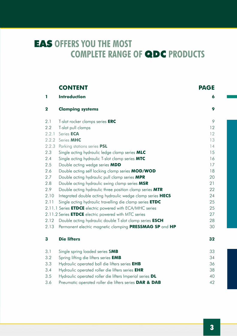
1 Introduction 6
2 Clamping systems 9 2.1 T-slot rocker clamps series ERC 92.2 T-slot pull clamps 12 2.2.1 Series ECA 12 2.2.2 Series MHC 13 2.2.3 Parking stations series PSL 142.3 Single acting hydraulic ledge clamp series MLC 15 2.4 Single acting hydraulic T-slot clamp series MTC 16 2.5 Double acting wedge series MDD 172.6 Double acting self locking clamp series MOD/WOD 182.7 Double acting hydraulic pull clamp series MPR 202.8 Double acting hydraulic swing clamp series MSR 212.9 Double acting hydraulic three position clamp series MTR 222.10 Integrated double acting hydraulic wedge clamp series HECS 242.11 Single acting hydraulic travelling die clamp series ETDC 252.11.1 Series ETDCE electric powered with ECA/MHC series 252.11.2 Series ETDCE electric powered with MTC series 272.12 Double acting hydraulic double T-slot clamp series ESCH 282.13 Permanent electric magnetic clamping PRESSMAG SP and HP 30
3 Die lifters 32
3.1 Single spring loaded series SMB 333.2 Spring lifting die lifters series EMB 343.3 Hydraulic operated ball die lifters series EHB 363.4 Hydraulic operated roller die lifters series EHR 383.5 Hydraulic operated roller die lifters Imperial series DL 403.6 Pneumatic operated roller die lifters series DAR & DAB 42
CONTENT PAGE
EAS OFFERS YOU THE MOST COMPLETE RANGE OF QDC PRODUCTS

IDEAS EASCOME FROM
Complete QDC/SMED solut ions from one single source, EAS
Hydraulic clamping and multi
coupler solutions Hydraulic clamping, die lifting, pump unit with controls and pre roller solution
Hydraulic clamping, die handling, pump unit and controls as well as automatic multi coupler solutions
Die handling solutions
Clamping, pre rollers and die lifter solutions
Pneumatic innovative die lifters

5
4 Pump units and control 44
4.1 Manual operated series P-141 44 4.2 Air hydraulic pump series PATG 3102PB 44 4.3 Air hydraulic pump units series EPA 45 4.4 Double hydraulic check valve EDCV-1 46 4.5 Electric hydraulic pump units series EPE 47
5 Die handling systems 49 5.1 Pre rollers series PR 50 5.2 Die change cars 52 5.2.1 Manual die change cars 52 5.2.2 Electric powered die change cars 53 5.2.3 Rail guided die change cars 54 5.2.4 Air floating die change cars 57 5.3 Die change tables 57 5.4 Inspection units 58 5.5 Die splitters 59 5.6 Die tilting units 60 5.7 Die storage systems 61
6 Couplers 62
6.1 Mono couplers 626.2 Manual multi couplers 62 6.3 Automatic multi couplers 63
7 How to select the right clamp 65
PAGE

QD
C
6
Time is money
INTRODUCTION OF THE QUICK DIE CHANGE (QDC) CONCEPT
1 INTRODUCTION
THE QUICK DIE CHANGE / SMED PROGRAM The adoption of a QDC program is usually the result of a switch to a useful Just-In-Time(JIT) manufacturing system. The lean production method. JIT is the production of precisely the necessary quantity at the right time, with the objective of achieving exact performance to schedule. With JIT, there are no inventory buffers as with traditional inventory systems. The ideal lot size is one piece. Long lasting die changes are there for a waste of time and SMED (Single Minute Exchange of Dies) such as the EAS QDC solutions reduce the unproductive change over time of dies to minutes instead of hours.
YOUR BENEFITS:- Increased machine productivity- Reduced labour cost- Inventory reduction- Increased flexability- Faster response- Improved safety
STANDARDIZE CLAMPING HEIGHT AND SHUT HEIGHT Standardization of the clamping height will speed up die changes, avoid confusion and lead to safer set-ups. If one standard clamping height cannot be arrived at, it is imperative that the number of clamping heights are at least be minimized.If possible hydraulic clamping locations may be standardized to allow the use of fixed clamps. If that is not possible EAS offers magnetic clamping systems as the solution.
RETURN OF INVESTMENT CALCULATIONS (ROI)To make QDC work in your factory, you must have a clear understanding of the goals and a complete commitment of all parties involved. EAS offers you a detailed consultancy helping you which solution will bring the best R.O.I. for you. This to lower your manufacturing cost to a more competitive level. The following simplified formula will determine the capi-tal investment you can make with the payback period you want.
CI = (T x DC x M x TS)/14,4 or T= (CI x 14,4)/(DC x M x TS)
CI= capital investmentT = Payback time in monthsDC= Die changes per weekM = hourly cost machineTS= Time saved in minutes by QDC
Example:The total capital investment (CI)for a press is € 12.750,- for a set of clamps, die lifters , a pump unit and pre rollers.DC = 20 changes a weekM = € 75,- per hourTS = 20 minutes saving per die change
The payback time in months T= (12750x14,4)/( 20x75x20) = 6.0 months
Not included is possible labor savings, reduction of inventory, increased safety and improved working conditions.
Unproductive change over hours are reduced to only a few minutes.

QD
C
7
DEVELOPING A QDC SYSTEM
DETERMINE YOUR QDC REQUIREMENTSQuick Die Change systems can take literally hundreds of forms: developing the right system for YOUR needs may like an overwhelming task, but it is actually quite simple.As the following sample demonstrates, you need to select in the case of a hydraulic clamping system, the cylinders, die lifters, pre rollers and a power unit. Of course EAS is always around to support you with your selection.
Typical example with following press specifications:Press size 100 tonnesUpper die weight 0,65 tonnes Lower die weight 0,85 tonnesTotal die weight 1,5 tonnesMax press speed 50 strokes/minuteBolster depth or T-slot length is 900 mmDie depth is 500 mmSize of the T-slot is 22 mm DIN
CYLINDER SELECTION (see also page 65): The cylinder capacity is a function of the stripping force - that is the force required to separate the two die halves. If you do not know the press’s stripping force, simply multi ply the press size by 15% till 20% for the slide half and 5% for the bolster half to determine the required clamping force for each die half.In our example we will need a max stripping force of 20% of 100 ton makes 20 tonnes.
For presses that have an upper die half that weighs more than 2% of the press size and or the speed is more than 100 strokes/min., you will have to add about 10% more to compensate for the inertia force. Neither of these conditions applies in our example.
To determine the capacity needed for the slide and the bolster cylinders, divide the stripping force by the number of cylinders of which you need at least four.
20 tonnes: 4 = 5 tonnes per cylinder
Type MHC-70 or ECA 60 pull cylinders or the ERC 60 rocker clamp or the MOD 510 wedge cylinder can be chosen to pro-vide the right clamping force (see selection chart of different cylinders)
DIE LIFTER SELECTION:To determine what die lifter you need, you take the depth of the die = 500 mm and you look into the selection chart of the for example hydraulic operated die lifters for a 22 mm T-slot.As the bolster length is 900 mm, you might select the EHR-22-21 with a length of 880 mm and with a capacity of 19,9 kN. This means that if the die is rolling on two of these die lifters, you will have 3980 kg lifting capacity, enough for a die of 1500 kg (1,5 tonnes).
T-slot dimensions in mm according DIN 650
A Fmin
Fmax
B C H min
Hmax
N max
18H8 16 24 30-32 12-14 30 36 1,6
22H8 20 29 37-39 16-18 38 45 1,6
28H8 26 36 46-50 20-22 48 56 1,6
36H8 32 46 56-60 25-28 60 71 2,5

IDEAS EASCOME FROM
Pull cylinders on a large slide with parking stations
Pull cylinders on bolster with parking stations
Large press with MHC clamps, multi couplers, die lifters and pre rollers
Wedge clamps for pressbed clamping
Pneumatic operated die lifters. Easy to install, easy to remove
Rocker clamp with automatic movement by air cylinder

ERC
2 CLAMPING SYSTEMS
2.1 T-SLOT ROCKER CLAMPS SERIES ERC Single acting and 350 bar
Capacity: 20, 40, 60, 100, 160 and 250 kNWorking pressure: 350 barSingle acting spring returnTemperature range: 5°C till 200°C with Viton sealsFits in any T-slot according DIN 650Adjustable T-slot mounting for DIN 650 T-slot heights DESCRIPTIONThese single acting manual positioned rocker clamps are widely used on many QDC applications. Available with clamping forces from 20 kN till 250 kN and with 6 mm effective clamping stroke.Features:- Standard series of clamps for simple ordering and fast availability.- Now available with unique height adjustable pin to overcome large tolerances of standard T-slots.- Easy to set to the correct T-slot height.- Easy to switch to different machines/presses.- Lower risk of damaging the T-slot.
These clamping cylinders can easily be operated by the air operated hydraulic pumps from EASchangesystems.
On request also available as flange mounted version.
Also available with a 200 mm stroke air cylinder for auto-matic retraction from the die as well as automatic approach to the die instead of manual operation. Furthermore the cylinders can be equiped with a inductive sensor to switch of the air moving cylinder if the clamp reaches the die. For extra safety a pilot operatde check valve can be mounted into the circuit to avoid the loss of clamping force in case of leakage in hose, pipe or valve. Options M for movable, P for inductive sensor and V for check valve
9
ERC T nut version

10
Step
1: c
lam
ping
forc
e
How to fill in ordering code
20 = 20 kN 40 = 40 kN 60 = 60 kN
100 = 100 kN 160 = 160 kN 250 = 250 kN
Step
3: c
lam
phei
ght
3 mm
-6 mm
ERC2025 (RANGE 20-25 mm)30 (RANGE 25-30 mm)35 (RANGE 30-35 mm)40 (RANGE 35-40 mm)
ERC4030 (RANGE 25-30 mm)35 (RANGE 30-35 mm)40 (RANGE 35-40 mm)45 (RANGE 40-45 mm)50 (RANGE 45-50 mm)
ERC6040 (RANGE 35-40 mm)45 (RANGE 40-45 mm)50 (RANGE 45-50 mm)55 (RANGE 50-55 mm)60 (RANGE 55-60 mm)
ERC10040 (RANGE 35-40 mm)45 (RANGE 40-45 mm)50 (RANGE 45-50 mm)55 (RANGE 50-55 mm)60 (RANGE 55-60 mm)
ERC16050 (RANGE 45-50 mm)55 (RANGE 50-55 mm)60 (RANGE 55-60 mm)65 (RANGE 60-65 mm)70 (RANGE 65-70 mm)
ERC25060 (RANGE 55-60 mm)65 (RANGE 60-65 mm)70 (RANGE 65-70 mm)75 (RANGE 70-75 mm)80 (RANGE 75-80 mm)
Step
2: T
-slo
t size
ERC20
1822
ERC40
1822
ERC60
2228
ERC100
2228
ERC160
2836
ERC250
2836
18 H8
22 H8
28 H8
36 H8
T-SLOTACC. TO DIN650

11
• Single acting cylinder• Availiable in 20, 40, 60, 100, 160 and 250 kN• Fits in any T-slot according to DIN 650
• Adjustable T-slot pin to fit your machine• Max. working pressure 350 bar• Temperature range 5 °C - 200 °C
Step
6: o
ptio
nal
chec
k va
lve
Fill in ‘V’ VCV-1
Step
5: o
ptio
nal
indu
ctiv
e se
nsor
Fill in ‘P’
PSM12NO
Step
4: o
ptio
nal
air m
ovab
le
Fill in ‘M’(Available on the 20, 40, 60 & 100 models)
MAC-200
ERCCLAMPING FORCE T-SLOT CLAMPHEIGHT AIR MOVABLE PROX. SWITCH CHECK VALVE
... T.. ... . . . For example: ERC60T2250
MANDATORY OPTIONALORDER SEPERATELY
ERCEAS TYPE Clamping Operating Cylinder Oil Dimensions in [mm] EAS TYPE
Force Pressure Weight Volume [kn] [bar] [kg] [cm3] (T) (H) G1 G2 R S J K L M O P a b Y (T-slot size) (backplate) (max.) ERC 20 20 350 2,7 5,7 18 or 22 25 to 40 T+43 T+60 55 62 22 15 95 40 30 G1/4” 6 3 4 ERC 20ERC 40 40 350 4,5 10,6 18 or 22 30 to 50 T+48 T+66 70 77 22 15 110 40 30 G1/4” 6 3 4 ERC 40ERC 60 60 350 7,4 17,0 22 or 28 40 to 60 T+58 T+80 80 87 22 15 130 40 30 G1/4” 6 3 4 ERC 60ERC 100 100 350 12,2 27,1 22 or 28 40 to 60 T+73 T+92 90 97 25 18 160 50 40 G1/4” 6 3 4 ERC 100ERC 160 160 350 21,5 42,4 28 or 36 50 to 70 T+93 T+110 110 120 25 18 192,5 50 40 G1/4” 6 3 4 ERC 160ERC 250 250 350 39,7 66,3 28 or 36 60 to 80 T+118 T+136 130 140 30 22 242,5 70 40 G1/4” 6 3 4 ERC 250
SELECTION CHART

ECA
12
2.2 T-SLOT PULL CLAMPS SERIES ECA AND MHC
DESCRIPTIONThese single acting manual positioned hollow pull cylinders are widely used on many QDC applications. Available with clamping force from 40 till 250 kN and with 8 mm stroke they fit many applications.
Ordering code: ECA –A/B/C/S
A= clamping capacity in kN, being 40, 60, 100, 160 and 250B= T-slot dimension ‘A” in mm, being 22, 28 or 36C= distance H +F in mm. (H= backplate height)S = only if equipped with air operated cylinder with max 200 stroke (others on request)
Capacity: 40, 60, 100, 160 and 250 kN at 350 barWorking pressure: 350 barSingle actingTemperature range: 5ºC till 200ºCViton seals
Single acting
EAS has two product lines of the T-slot pull cylinders, the ECA series suitable for normal QDC applications and the high quality MHC series for heavy duty QDC applications.
2.2.1 ECA SERIES
2 CLAMPING SYSTEMS
Order Code Example: ECA 40-22-70 is a 40 kN clamp with the distance H+F of 70 mm and for a 22 mm DIN T-slot. ECA 40-22-70-150 is the same cylinder but in addition to that an air cylinder to move the clamp into the T-slot with a stroke of 150 mm.
Single acting, 350 bar
SELECTION CHART
EAS Model Number Clamping force in
(kN)
Operatingpressure
(bar)
Stroke
(mm)
Oilcapicity(cm3)
MaxH+F(mm)
Dimensions in mm
A. B C D E F G I Lmax
ECA 40/18/.. 40 350 8 8,5 90 18 37 16 65 58 * G 1/4” 25 18
ECA 40/22/.. 40 350 8 8,5 90 22 37 16 65 58 * G 1/4” 25 18
ECA 60/18/.. 60 350 8 13,5 100 18 46 20 72 65 * G 1/4” 25 18
ECA 60/22/.. 60 350 8 13,5 100 22 46 20 72 65 * G 1/4” 25 18
ECA 100/22/.. 100 350 8 23 110 22 46 20 82 71 * G 1/4” 28 20
ECA 100/28/.. 100 350 8 23 110 28 46 20 82 71 * G 1/4” 28 20
ECA 160/28/.. 160 350 8 38 120 28 56 25 106 82 * G 1/4” 40 25
ECA 160/36/.. 160 350 8 38 120 36 56 25 106 82 * G 1/4” 40 25
ECA 250/36/.. 250 350 8 57 140 36 56 25 127 100 * G 1/4” 50 25
MH
C
13
2.2.2 MHC SERIES
SELECTION CHART
EAS Model Number
Clamping force (kN)
Operatingpressure
(bar)
Stroke
(mm)
Oil capacity
(cm3)
Max h+ d(mm)
Dimensions in mm
A. B C F D E G I Lmax
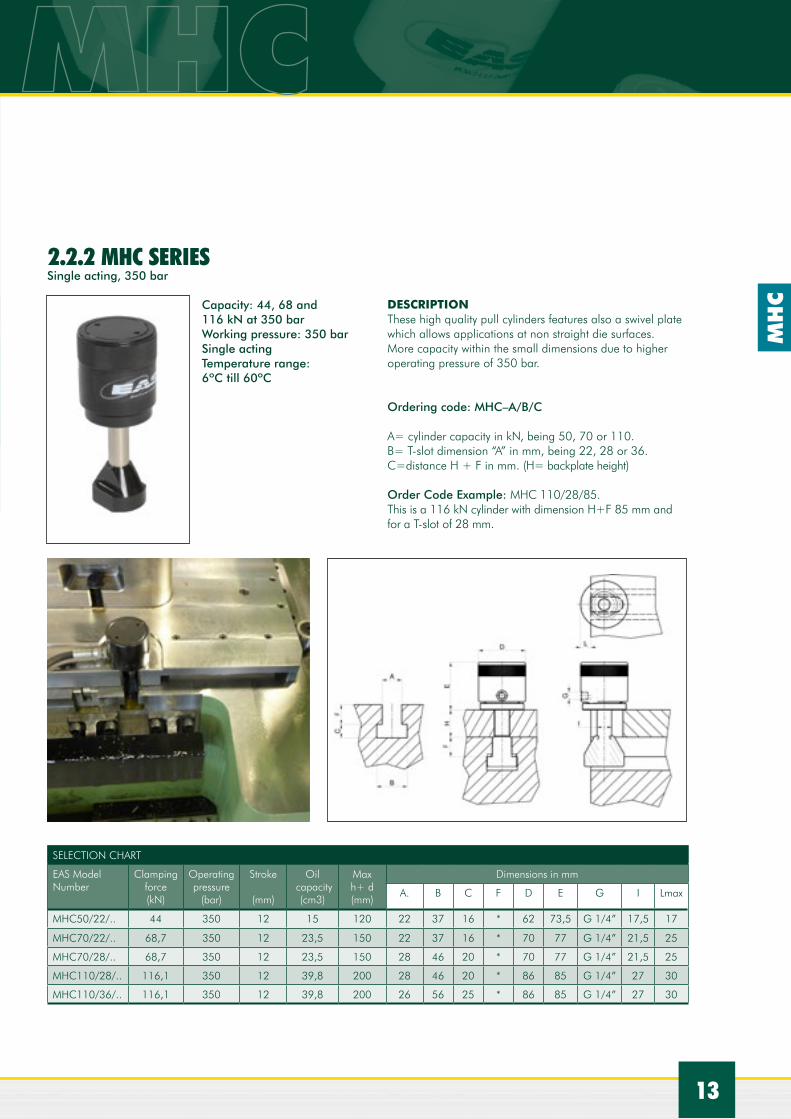
MHC50/22/.. 44 350 12 15 120 22 37 16 * 62 73,5 G 1/4” 17,5 17
MHC70/22/.. 68,7 350 12 23,5 150 22 37 16 * 70 77 G 1/4” 21,5 25
MHC70/28/.. 68,7 350 12 23,5 150 28 46 20 * 70 77 G 1/4” 21,5 25
MHC110/28/.. 116,1 350 12 39,8 200 28 46 20 * 86 85 G 1/4” 27 30
MHC110/36/.. 116,1 350 12 39,8 200 26 56 25 * 86 85 G 1/4” 27 30
DESCRIPTIONThese high quality pull cylinders features also a swivel plate which allows applications at non straight die surfaces.More capacity within the small dimensions due to higher operating pressure of 350 bar.
Ordering code: MHC–A/B/C
A= cylinder capacity in kN, being 50, 70 or 110.B= T-slot dimension “A” in mm, being 22, 28 or 36.C=distance H + F in mm. (H= backplate height)
Order Code Example: MHC 110/28/85.This is a 116 kN cylinder with dimension H+F 85 mm and for a T-slot of 28 mm.
Capacity: 44, 68 and 116 kN at 350 bar Working pressure: 350 barSingle actingTemperature range: 6ºC till 60ºC
Single acting, 350 bar

MH
C
14
Ordering code: PSL-T-AT= T-slot size being 18, 22, 28 of 36A= Distance H+F in mm of the pull cylinder
Order code exaple: PSL-28-60This is a Parking Station for a ECA cylinder for a T-slot 28 mm with distance H + F = 60 mm With a Connection Block. Please order a extra model number CB-1.
In case a connecting block with pilot operated check valve is required order extra CBCV-1.
2 CLAMPING SYSTEMS
DESCRIPTIONDuring a die change it s very convenient to ”park” the cylinder connected to the hose on to the press. This will avoid that the cylinders are being damaged when laying on the floor.EAS offers just very simple parking stations PSL in which the cylinders with their T stone are being parked as well as parking stations combined with a Connecting Block for connecting pipes and hoses, type CB-1 with 3 G 1/4’ oil connections.If furthermore for extra safety a pilot operated check valve in the connecting block is required type CBCV-1 is available.Dimensions on request.
2.2.3 PARKING STATIONS FOR T-SLOT ECA AND MHC PULL CYLINDERS
SERIES PSL
SELECTION CHART
EAS Model Number
Dimensions in mm
B C
PSL 18 .. 50 76
PSL 22 .. 53 83
PSL 28 .. 70 91
PSL 36 .. 78 110

15
MLC
DESCRIPTIONThis clamping manifold includes 4, 6 or 8 modular single acting spring return cylinders. The manifolds (2) are mounted at the side of the table, which enables the die to be loaded from the operating side towards a fixed stop. With a different support block heights can be adapted to the die clamping height. In case of mounting at the top this solution also avoid the die half from falling.
Ordering code: MLC-604/S
S = the height S in mm of the in between block. This has to be the die clamping height + 3 mm in view of the 8 mm stroke of the cylinders. In case only the hydraulic clamping bar is needed, please order just MLC604, MLC906 or MLC1208.
Single acting and 350 bar
Capacity: 63, 95 and 127 kNWorking pressure: 350 barSingle actingTemperature range: 5ºC till 60ºC
2.3 LEDGE CLAMPS, SERIES MLC
SELECTION CHART (FOLLOW UP)
EAS Model Number
Dimensions in mm
A B C D E F G H I K L M N O P R S T
MLC 604/.. 215 80 40 60 14 12 G 1/4” 20 13 17 30 17,5 40 30 45 8 * 42
MLC 906/.. 305 80 40 60 14 12 G 1/4” 20 13 17 30 17,5 40 30 45 8 * 42
MLC 1208/.. 395 80 40 60 14 12 G 1/4” 20 13 17 30 17,5 40 30 45 8 * 42
* to be specified per application
SELECTION CHART
EAS Model Number
Clamping force (kN)
Operatingpressure
(bar)
Stroke
(mm)
Oil capacity
(cm3)
MLC 604 63,4 350 8 14,5
MLC 906 95,1 350 8 21,7
MLC 1208 126,8 350 8 28,9

MTC
16
DESCRIPTIONBecause of their compact sizes the MTC clamps are very suitable to place them manually into the T-slots and slide them against the die. As these clamps can be moved into the T-slots, they are very suitable for different sizes of dies. Also because of their large stroke range, different die heights can be easily clamped. A set screw in the back can be used to lock the clamp in the T-slot if required.
Ordering code; MTC A-B-C
A= clamping force in kN , being 15, 30, 45 or 70.B= dimensions of the T-slot, being 22, 28 or 36.C= clamping height H being 25 or 30mm, others on request.
Ordering Code Example: MTC 15/22/25 is a 15 kN clamp with X height between 20 and 25 mm and for 22 mm T-slot.
In case only the hydraulic clamping cylinder is needed (without T stone part) please order just MTC15, MTC30, MTC45 or MTC70.
Please specify your T-nut dimensions
Single acting and 350 bar
Capacity: 16, 28, 44 and 68 kNWorking pressure: 350 barSingle actingTemperature range: 5ºC till 200ºC, with viton seals
2.4 T-SLOT CLAMPS SERIES MTC
SELECTION CHART
EAS Model Number
Clamping force (kN)
Operatingpressure
(bar)
Stroke
(mm)
Oil capacity
(cm3)
Dimensions in mm
A B C E G L O P Q R
MTC 15/18/25 16,8 350 8 3,9 95 65 40 24 G 1/4” 77 63 100 34 28
MTC 15/22/25 16,8 350 8 3,9 95 65 40 24 G 1/4” 77 63 100 34 35
MTC 15/28/25 16,8 350 8 3,9 95 65 40 24 G 1/4” 77 63 110 44 44
MTC 15/28/30 16,8 350 8 3,9 95 65 40 24 G 1/4” 77 63 110 44 44
MTC 15/36/30 16,8 350 8 3,9 95 65 40 24 G 1/4” 77 63 110 56 54
MTC 30/18/25 28 350 8 6,5 104 65 47 32 G 1/4” 81 63 100 34 28
MTC 30/22/25 28 350 8 6,5 104 65 47 32 G 1/4” 81 63 100 34 35
MTC 30/28/25 28 350 8 6,5 104 65 47 32 G 1/4” 81 63 110 44 44
MTC 30/20/30 28 350 8 6,5 104 65 47 32 G 1/4” 81 63 110 44 44
MTC 30/36/30 28 350 8 6,5 104 65 47 32 G 1/4” 81 63 110 56 54
MTC 45/18/25 43,7 350 8 10,1 111 65 50 40 G 1/4” 85 63 100 34 28
MTC 45/22/25 43,7 350 8 10,1 111 65 50 40 G 1/4” 85 63 100 34 35
MTC 45/28/25 43,7 350 8 10,1 111 65 50 40 G 1/4” 85 63 110 44 44
MTC 45/28/30 43,7 350 8 10,1 111 65 50 40 G 1/4” 85 63 110 44 44
MTC 45/36/30 43,7 350 8 10,1 111 65 50 40 G 1/4” 85 63 110 56 54
MTC 70/28/30 68,2 350 12 23,5 132 80 75 50 G 1/4” 99 72 130 44 44
MTC 70/36/30 68,2 350 12 23,5 132 80 75 50 G 1/4” 99 72 130 56 54
2 CLAMPING SYSTEMS

17
MD
D
Double acting , max 200 bar
Capacity: 60, 110, 200 and 400kN Plunger with 20° angleWorking pressure: 200 bar (other on request)Double acting Temperature range: 5°C till 60°C
2.5 WEDGE CLAMP SERIES MDD WITH 20° PLUNGER END
DESCRIPTIONThese double acting clamps feature a 20 degree angle at the end of the clamping plunger which require a 20 degree angle on the to be clamped tool. If the tool does not have the 20 degree angle the MOD series of the next page need to be selected.
Ordering code: MDD -A-B-C-D-M (see also page 19)
A = means the different sizes of clamps being 610, 1010, 2010 or 4010B = nominal backplate height x 0,1 mmC = mounting position of the bolts x 0,1 mmD = mounting position of dowel pins x 0,1 mmM = metric bolt size
Ordering Code Example: MDD-610-350-200-400-M20M = metric MDD series, 610 means the 60 kN model, 350 means a backplate height of 35,0 mm, 200 means C = 20 mm, 400 means D = 40 mm and M20 means a mounting bolt of M20.
Cylinders come with mounting brackets for inductive sensors to determine the clamped and unclamped position. Inductive sensor need to be ordered extra under model num-ber PSM12NO.
Cables: SCS5 straight connector 5 m length SCS15 straight connector 15 m length SCEL5 elbow connector 5 m length SCEL15 elbow connector 15 m length
Dimension on request

MO
D/W
OD
18
2 CLAMPING SYSTEMS
Double acting, max 200 bar
Capacity: 15, 30, 60, 110, 200, 400 and 1200 kNWorking pressure: 70 bar, retracting pressure 200 barDouble actingTemperature range: 5ºC till 60ºC
2.6 SELF LOCKING WEDGE CLAMP SERIES MOD
DESCRIPTIONIdeal clamp for fully automated QDC systems. A typical clamping systems consists of 4 double acting cylinders mounted on the lower bed. Due to the 5 degree wedge angle, these cylinders are self locking even without hydraulic pressure, which is an important safety feature. For additional safety at QDC applications, continuous hydraulic pressure is recommended. On each clamp two inductive sensors can be installed to indicate the clamped and retracted position of the plunger. To be ordered as extra. Metric versions are available under the MOD series and Imperial versions with SAE oil connections are available under the series WOD.
SELECTION CHART
EAS Model Number
Clamping force (kN)
Operatingpressure
(bar)
Stroke
(mm)
Retract pressure
(bar)
Max flow
(l/min.)
Back plateheight H
(mm)
MOD 150 15 70 15 200 2 17-27
MOD 250 30 70 30 200 4 17-27
MOD 510 60 70 35 200 6 25-40
MOD 1010 110 70 35 200 10 32-40
MOD 2010 200 70 35 200 10 36-40
MOD 4010 400 70 40 200 16 50-*
MOD 12030 1200 70 80 200 34 80-*
SELECTION CHART (FOLLOW UP)
EAS Model Number
Dimensions in mm
A A1 B C D F G H I K M P R R2 R3 U
MOD 150 125 57 141 118 72 17,4 G1/4” 86 58 M12 12,5-35 13 X+41 X+35 X+50 35
MOD 250 157 65 187 147 105 25,4 G1/4” 123 79 M16 15,0-55 25 X+62 X+50 X+69 70
MOD 510 206 66 241 194 120 34,9 G1/4” 162 108 16-M20 20-70 30 X+78 X+65 X+89 70
MOD 1010 235 65 270 221 160 47,6 G3/8” 178 125 16-M24 20-90 30 X+104 X+92 X+114 105
MOD 2010 237 63 272 222 190 56 G3/8” 178 125 M24 25-80 30 X+110 X+92 X+123 140
MOD 4010 308 68 353 284 210 79,5 G3/8” 230 158 27-M36 30-85 40 X+158 X+136 X+172 140
MOD 12030 on request
*Please indicate your backplate height; higher backplate heights are possible wih an extra filling plate.
*Please indicate your backplate height; higher backplate heights are possible wih an extra filling plate.

MO
D/W
OD
19
SELECTION CHART INDUCTIVE SENSORS AND CABLES
EAS Model Number
Thread Specs Detectiondistance
PSM12NO Normally open
M12x1 10-30V, DC150mA
3 mm
SCEL5SCEL15SCSL5SCSL15
90 degree elbow with 5 meter cable90 degree elbow with 15 meter cableStraight connector with 5 meter cableStraight connector with 15 meter cable
Ordering code:As these cylinders can be ordered for several backplate heights and the mounting screws at different locations the following ordering code is valid:
MOD-A-B-C-D-M-VM for metric version and W for the imperial version of the cylinder.A = means the different sizes of clamps, being 150, 250, 510, 1010, 2010, 4010 or 12030.B = nominal backplate height x 0,1 mmC = mounting position M of the bolts x 0,1 mmD = mounting position of dowel pins x 0,1 mmM = metric bolt sizeV = Viton seals
Ordering Code Example: MOD -510-250-200-400-M20M= metric MOD series , 510 means the 60 kN model, 250 means a back plate height of 25,0 mm, 200 means dimension C = 20,0 mm, 400 means dimension D = 40,0 mm and the M20 means a mounting bolt M20 and without inductive sensors.

MP
R
20
2 CLAMPING SYSTEMS
Double acting, max 350 bar
Capacity: 56, 91 and 143 kNWorking pressure: 350 barDouble actingTemperature range: 5ºC till 60ºC
2.7 PULL CYLINDERS SERIES MPR
DESCRIPTIONThe EAS pull cylinders are very suitable to clamp dies on press beds. In that case it is necessary to have T-slots on the dies. The die should be moved over the pullarm of the cylinder and also in the same direction of the clamps (see application drawing).
For Viton seals (max 200ºC) add V behind the modelnumber, like for example MPR 51-V
In case 2 sensors are required to determine the extended in the clamped position add suffix “P” behind the modelnumber and order the sensors (5 m cable included).
SELECTION CHART
EAS Model Number
Clamping force (kN)
Operatingpressure
(bar)
Stroke
(mm)
Oil capacity
(cm3)
Oil retractcapacity(cm3)
Maxflow
(l/min)
MPR 51 56 350 10 16 23 2,5
MPR 91 91 350 10 26 38 8,6
MPR 141 143 350 10 41 61 15
SELECTION CHART (FOLLOW UP)
EAS Model Number
Dimensions in mm
A B D D1 E F G H H1 H2 K1) K1 K2 L Q S U V W
MPR 51 137,5 85 82 128 54 30 G 1/4” 54 36 58 17 52,5 53 20 M20X1,5 51S*=26,5-34,5 104 13 13
MPR 91 169 100 104 160 70 40 G 3/8” 76 48 82 24 69 70 28 M30X1,5 91S*=36-44 130 17,5 17
MPR 141 201 115 126 192 90 50 G 3/8” 86 58 92 30 86 87 35 M36X1,5 141S*=47-55 156 21 21
SELECTION CHART INDUCTIVE SENSORS
EAS Model Number
Thread Specs Detectiondistance
PSM8NOCNormally open
M8x1 10-36V, DC100mA
2 mm

MSR
21
Double acting, max 350 bar
Capacity: 56, 91 and 143 kNWorking pressure: 350 barDouble actingTemperature range: 5ºC till 60ºC
2.8 SWING CLAMP CYLINDERS SERIES MSRDESCRIPTIONThe EAS swing clamp arm swings 90 degrees and then clamps vertically. Ideal for mounting beneath the surface bed or bolster surface to allow unobstructed part or die loading and unloading. For the clamping arm it is required to mount flanges on the dies or to have T-slot openings.
In case two sensors are required to determine the extended and the clamped position add suffix ‘P” behind the model number and order the inductive sensors and cables. For example MSR 51 P. These sensors are mounted at the bottom of the cylinders. Dimensions on request. For Viton seals (max 200ºC) add V behind the model number like for example MSR-51-V. For flange mounted oil connections order model number with F. For example MSR-91-F.For F series dimensions on request.
SELECTION CHART (FOLLOW UP)
EAS Model Number
Dimensions in mm
A B D D1 E F G H H1 H2 K K1 K2 L Q S U V W Z H3 H4 N
MSR 51 157 105 82 128 54 30 G1/4” 33 37 70 17 52 53 20 M20X1,5 51S*=16-21 104 13 13 6 65 70 15
MSR 91 178 115 104 160 70 40 G3/8” 40 46 86 24 63 66 28 M30X1,5 91S*=20-25 130 18 17 6 80 86 8
MSR 141 224 140 126 192 90 50 G3/8” 50 58 103 30 84 87 35 M36X1,5 141S*=25-30 156 21,5 21 8 95 103 10
SELECTION CHART
EAS Model Number
Clamping force (kN)
Operatingpressure
(bar)
Stroke*total(mm)
Strokeclamp(mm)
Oil capacity
(cm3)
Oil retractcapacity(cm3)
Maxflow
(l/min)
MSR 51 56 350 20 5 32 46 1,5
MSR 91 91 350 20 5 52 76 1,5
MSR 141 143 350 30 5 123 183 2,5
SELECTION CHART INDUCTIVE SENSOR AND CABLES
EAS Model Number
Thread Specs Detectiondistance
PSM8NONormally open
M8X1 10-30V, DC150mA
3 mm
SCEL5SCEL15SCSL5SCSL15
90 degree elbow with 5 meter cable90 degree elbow with 15 meter cableStraight connector with 5 meter cableStraight connector with 15 meter cable

MTR
22
2 CLAMPING SYSTEMS
Four oil connections, 350 bar
Capacity: 56, 91 and 143 kNWorking pressure: 350 barFour oil connectionsTemperature range: 5ºC till 60ºCHorizontal 90 degrees rotation in extended clamping arm position.
2.9 THREE – POSITION SWING CYLINDERS SERIES MTR
DESCRIPTIONDouble acting three position cylinders are designed to be integrated on machine tables and on moving bolsters.Due to the fact that the clamping arm is retracted completely and disappearing under the working table, the die load or unload surface becomes totally free.
Three position swing cylinders are particularry recommended when the application requires an integrated clamping solution on machine tables or when there is a narrow space and limited access.
Piston rotation is obtained through a mechanical device activated by two independent lines (ports C and D) while the straight action of the piston is provided by two other lines(ports A and B).
The clamping arm’s position( clamped /unclamped) can be controleed by two proximity switches (to be ordered extra) while the straight stroke can be controlled by pressure switches. This cylinder guarantees a correct rotation of the arm avoiding inconveniences like jamming and cycle dephasing that would normally happen with similar products when the clamping arm bumps against the die.
For Viton seals (max 200ºC) add V behind the model number.For exmaple MTR-141-V .

MTR
23
SELECTION CHART INDUCTIVE SENSOR AND CABLES
EAS Model Number
Thread Specs Detectiondistance
PSM12NCNormally closed
M12x1 10-30V, DC150mA
3 mm
SCEL5SCEL15SCSL5SCSL15
90 degree elbow with 5 meter cable90 degree elbow with 15 meter cableStraight connector with 5 meter cableStraight connector with 15 meter cable
SELECTION CHART
EAS Model Number
Clamping force (kN)
Operatingpressure
(bar)
Stroke
(mm)
Fclamp
(kN)
Qretr
(cm3)
Qext
(cm3)
Maxflow
(l/min)
Dimensions in mm
A B C D D1 E F
MTR 51 56 350 43 55,4 68,6 98 2 246 204 43 82 128 54 30
MTR 91 91 350 56 90,7 145,1 211 2 305 250 56 104 160 70 40
MTR 141 154 350 67 153,9 294,7 426 2 356 290 67 126 192 90 50
FLANGES FOR DIE MOUNTING For cylinders MTR and MSR
SELECTION CHART
EAS Model Number
Dimensions in mm
A B C D Emin Emax F G H I L
MAD 3.50 128 104 70 37 19 22 13 20 13 - -
MAD 3.90 160 130 86 46 25 28 18 26 17 - -
MAD 3.140 192 156 103 58 30 33 22 33 21 - -
MAD 4.50 128 104 - - 19 22 13 20 13 70 43
MAD 4.90 160 130 - - 25 28 18 26 17 86 56
MAD 4.140 192 156 - - 30 33 22 33 21 103 67
SELECTION CHART (FOLLOW UP)
EAS Model Number
Dimensions in mm
G1 G2 H H1 H2 H3 K K1 K2 L N Q S U V W Z
MTR 51 G 1/4” G 1/8” 33 37 65 70 17 42 43 50 55 M20X1,5 19-22 104 13 13 6
MTR 91 G 3/8” G 1/8” 40 46 80 86 24 55 56 61 55 M30X1,5 25-28 130 17,5 17 8
MTR 141 G 3/8” G 1/4” 50 58 95 103 30 66 67 72 55 M36X1,5 30-33 156 22 21 8

HEC
S
24
SELECTION CHART
EAS Model Number
Clamping force (kN)
Opperating pressure
(bar)
Outside diameter
(mm)
Cylinder length (mm)
Related bolt
number
Bolt diameter
(mm)
HECS 40 75 140 88 108 EEB 40/41 40
HECS 70 150 140 120 145 EEB 70/71 70
HECS 95 225 140 165 233 EEB 95 95
HECS 120 300 140 210 245 EEB 120 120
HECS 135 400 140 210 245 EEB 135 135
2 CLAMPING SYSTEMS
2.10 INTEGRATED DOUBLE ACTING WEDGE CLAMP SERIES HECS
DESCRIPTIONThis integrated hydraulic clamping system is mounted on the side of the press upper and lower bed, leaving the platen face completely free of obstructions. Depending on the press size the die is usually clamped using 2 or 4 clamps per platen. Each die would have the corresponding number of EEB clamping bolts mounted on each side of the die. While these bolts are sticking out these systems are usually only used at the upper bed side of the press. Clamping is achieved when the cylinder moves the wedge on the end of the plunger into the matching wedge shaped slot in the clamping bolt.This system can only be applied on new presses where the platens can be easily modified to accept the system.Information about mounting holes is available from your EAS source.
For more detailed information ask EAS.
Double acting and 140 bar
Capacity: 75, 150, 225, 300 and 400 kNWorking pressure: 140 barDouble actingTemperature range: -20ºC till + 80 ºC
For more detailed information ask EAS.

ETD
CE
+ E
CA
25
2.11 SINGLE ACTING HYDRAULIC TRAVELLING DIE CLAMP
2.11.1 ELECTRIC POWERED ETDCE WITH ECA/MHC CYLINDERSingle acting hydraulic clamping cylinder, electric powered into the T-slot. Hydraulic pressures 350 bar
Available with ECA or MCH hollow ram pull cylinders Clamping capacity range 40, 60 or 100 kN Travel distance: 400 towards 1200 mmTravel speed: 100-150 mm/secTemperature range: 5°C till 60°C
DESCRIPTIONTravelling die clamps are used for automatic clamping applications on the upper bed of mainly large presses.The single acting hydraulic clamping cylinder is mounted to a chain which travels into the T-slot of the press upper bed. This chain is in this case driven by an electric motor.The hydraulic clamp is normally retracted in the so called park position and is controlled by a sensor. When the cylinder travels into the T-slot and reaches the to be clamped die, another sensor will indicate that the clamp has reached his position and the travel drive switches off. Hydraulic hose and sensor cable are travelling inside the chain with the cylinder in the T-slot.No standardization of the back plate die required.The rigid construction is to withstand vibrations and shocks from the press operation.
Ordering code example: ETDCE 10-50-600-36
ETDCE = EAS Travelling Die Clamp Electric1 = clamping force 4 = 40 kN, 6 = 60 kN and 10 is 100 kN2 = clamping height H in mm3 = travelling stroke in mm4 = T-slot size
Ordering code example: ETDCE 10-50-600-36, this is an electric powered traveling die clamp with a 100 kN hollow clamp cylinder type ECA 100 with 50 mm clamping height and a 600 mm travelling stroke for a 36 mm DIN 650 T-slot.
ETDCE with MHC hollow ram cylinder

ECA
26
2 CLAMPING SYSTEMS
SELECTION CHART
EAS Model Number
Air pressure
(bar)
Hydraulic pressure
(bar)
Moving speed
(mm/sec)
Dimensions in mm
A B C D E F G H I J K L
ETDCE-4 4 250 100-150 195 187 85 94,5 59 73 25 * 130 145 140 S/2+435
ETDCE-6 4 250 100-150 195 187 85 94,5 49 88 30 * 130 145 140 S/2+435
ETDCE-10 4 250 100-150 195 187 85 94,5 42 108 40 * 130 145 140 S/2+435
For more detailed information ask EAS.”
ETD
CE
+ M
TC
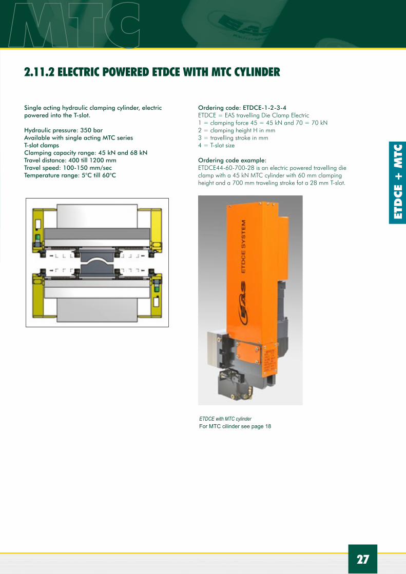
2.11.2 ELECTRIC POWERED ETDCE SERIES MTC
Ordering code: ETDCE-1-2-3-4ETDCE = EAS travelling Die Clamp Electric1 = clamping force 45 = 45 kN and 70 = 70 kN2 = clamping height H in mm3 = travelling stroke in mm4 = T-slot size
Ordering code example: ETDCE44-60-700-28 is an electric powered travelling die clamp with a 45 kN MTC cylinder with 60 mm clamping height and a 700 mm traveling stroke fot a 28 mm T-slot.
Single acting hydraulic clamping cylinder, electric powered into the T-slot.
Hydraulic pressure: 350 barAvailable with single acting MTC series T-slot clampsClamping capacity range: 45 kN and 68 kN Travel distance: 400 till 1200 mmTravel speed: 100-150 mm/secTemperature range: 5°C till 60°C
ETDCE with MTC cylinder For MTC cilinder see page 18
27
2.11.2 ELECTRIC POWERED ETDCE WITH MTC CYLINDER

ESCH
28
2 CLAMPING SYSTEMS
2.12 DOUBLE ACTING HYDRAULIC DOUBLE T-SLOT CLAMP, SERIES ESCH
DESCRIPTIONDouble acting T-slot clamps are used on the press table to lift, roll and clamp the die on the bolster table. These products are mounted easily into the standard T-slot of the bolster and on the die they also fit T-slots. By actuating the lifting port the upper roller part lifts the die from the bolster table and the die can roll over the rollers in and out the press. By actuating the upper port the plungers go down and the bar clamps the die onto the bolster table. The first rollers are specially hardened and protected against the first ‘contact “ with the die. Available in different length as the products can be connected to each other and this product is available for 2 DIN 650 T-slots sizes, 22 and 28 mm. For only clamping the die against the slide with a similar double T-slot clamps ask your EAS contact as these are also available on special request.
Ordering code: ESCH-A-BA= the T-slot size: 22 and 28B = length of the clamp
RemarkThe double T-slot clamp is a very interesting combination of clam-ping and die lifting combined in one product.Due to the applications of this product EASchangesystems does not deliver this product as a standard component but wants to discuss and review first with you your application.The usage of this product without consulting EASchangesystems may result in damage of the first rollers due to misalignments. If smaller dies are used then the length of this product other issues may appear. In case of scrap holes please also request us for the right solutions.
Double acting, 350 bar
For T-slot DIN 650, size 22 and size 28Lifting capacity: 12,5 kN till 60,3 kNWorking pressure: 350 barTemperature range: 5°C till 60°CSpecial hardened first roller with protection

IDEAS EASCOME FROM
Swivel pre rollers which are also movable along the press bed.
Stamping press equiped with mova-ble pre rollers, double T-slot clamps on bolster and slide and chain push/pull device.
The T-slot on the slide are equiped with double T-slot clamps without rollers.
Our application engineers found the right solution together with the customer.
2929

SP
30
Bolster plate with side guiding die stop and air die lifters. Pressmag SP100 system with resin sealing.
2 CLAMPING SYSTEMS
2.13 PERMANENT ELECTRIC MAGNETIC CLAMPING SYSTEMS SERIES PRESSMAG SP AND HP
The primary advantage of magnetic clamping is that it avoids the need for standardized back plates.
Our Pressmag systems are EASy to install and EASy to operate. No modifications to the press are required as the system is mounted with bolts to existing T-slots or tapped holes. One operator can operate the die clamping in a safe way, standing outside the press.
EAS Pressmags are safe as the magnetic force stays on, even when an electrical break down takes place. After magnetizing the plates the clamping force stays always in place until the moment of demagnetizing. EAS Pressmags do not magnetize the entire die as the magnetic flux penetrates the die only 20 mm. There for the die face and the to be stamped part will not be magnetized, allowing also scap removal.EAS offers two different systems the Pressmag SP 100 MM and the Pressmag HP.
The Pressmag SP system is based on 47x 47 mm square invertible ALNICo magnets, surrounded by an isolated coil. On top is a round pole while each square is surrounded by not invertible permanent rare earth magnets.Clamping of the die is done for an unlimited time and without electrical energy nor generating heat. Another electric pulse will demagnetize the system, releasing the die.
Pressmag SP 100MM features: - Small square/round poles, resulting in high forces within limited areas.- Stainless steel mesh metal to metal seal for cleaner and longer life.- Standard for 100°C ( 212° F)- Plate thickness 38 mm, with T-slots it will be more.- Force per pole 2,2kN.
PRESSMAG SP100MM
MAGNETIZED DEMAGNETIZEDMagnetic Line Magnetic Line
Mold Mold
Stainless steel mesh
Clamp Plate
Adapter Plate
Coil
Electromagnetic Coil
Alnico Magnet
Rare Earth Permanent Magnet
Pressmag SP100MM slide plate with optional T-slots for mechanical locking devices.
Bolster plate with optional T-slots.

SP
31
The Pressmag HP system is a compensated system, meaning that NOT each pole is acting like a north or a south pole as the SP system but the long poles are acting as the north poles and the frame plate as the south pole.
To magnetize, the electric current in the coils reverse the polarity of the magnets. The magnetic fields generated by the magnets are oriented to the polar face of the chuck, which becomes active and the die is clamped.
A new electric current reverse the polarity of the magnets and turns off the system and demag is completed and the die is released.
Large Pressmag HP application
Slide plate with Pressmag SP100MM groups. Group of presses equipped with Pressmag SP100 as well as guiding, air operated die lifters and pre rollers from one source, EASchangesystems.
PRESSMAG HPThe long poles generate higher clamping forces while the magnetic flux is also working if only a part of the pole is covered by the die.
These systems are recommended for larger dies and higher forces.
Pressmag HP features:- Long poles with high flux concentration, even if poles are partly covered.- Standard up to 100°C - Plate thickness 55 mm- Force per pole 25 kN

MB
32
INTRODUCTIONFor a simple and quick movement of the dies on the press bed, EAS offers a comprehensive product portfolio of so called die lifters. When dies are weighing more than 500 kg the conventional way of changing dies becomes heavy, protracted and often dangerous. Long downtimes result in unproductive manufacturing. Die lifters make a die change easier and above all quick which increases the productivity.
These die lifters are spring, hydraulic or air operated lifting bars. On these bars are either balls or rollers mounted over which the die can be simply moved into its position or outside the press. These die lifters are fitting the standard DIN 650
metric T-slot dimensions as well as rectangular U shape slots and for the inch sizes of T-slot EAS offers the DL series.Normally the die lifters are just below the press bed surface and the die cannot be moved but after be activated by either a spring , by hydraulic pressure or by air pressure the die lifter is “lifted “ a few mm above the press bed surface, clearing the die from the bed, which makes it then easy and simple to move the die.
3 DIE LIFTERS

SM
B
33
3.1 SINGLE SPRING LOADED DIE LIFTER SERIES SMB
Simple spring loaded die lifers are very suitable for small and mid size dies. They do not require any power source. By closing and clamping the die the clamping elements overcome the spring force and clamp the die onto the press table. When the die clamps are released, the spring loaded balls lift the die back into its original position where it can be moved. The MB series can be mounted individual.
Available from 20kg till 100kg lifting capacity
SELECTION CHART
EAS Model Number
Lifting
(kg)
Capacity
(kN)
Dimensions in mm
Dia. Height Stroke
SMB 18 20 0,2 20 28,5 2,5
SMB 22 40 0,4 24 36 3
SMB 28 60 0,6 30 47 4
SMB 36 100 1 36 59 4,5
D
H
SELECTION CHART
EAS Model Number
Dimensions in mm
D H
SMB 18 20 Hg 28,5
SMB 22 24 Hg 36
SMB 28 30 Hg 47
SMB 36 40 Hg 59
To build in SMB series please manufacture holes arcording following dimensions:
34
EMB
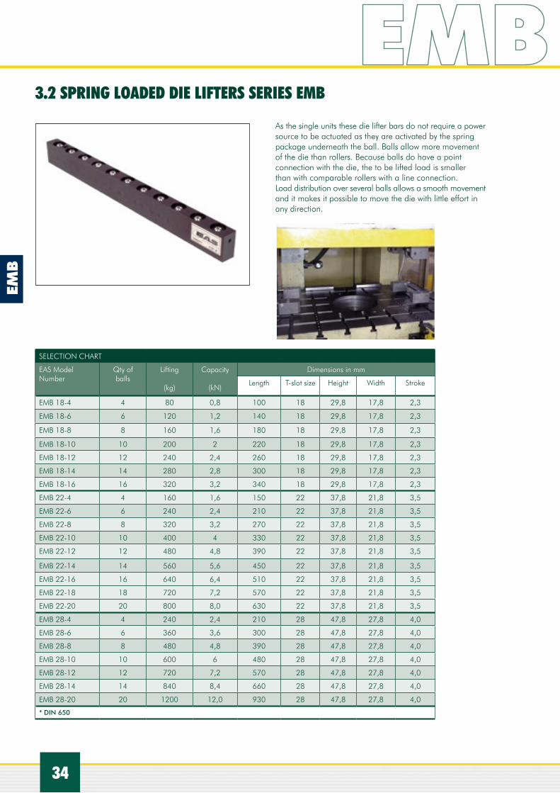
3.2 SPRING LOADED DIE LIFTERS SERIES EMB
As the single units these die lifter bars do not require a power source to be actuated as they are activated by the spring package underneath the ball. Balls allow more movement of the die than rollers. Because balls do have a point connection with the die, the to be lifted load is smaller than with comparable rollers with a line connection.Load distribution over several balls allows a smooth movement and it makes it possible to move the die with little effort in any direction.
SELECTION CHART
EAS Model Number
Qty ofballs
Lifting
(kg)
Capacity
(kN)
Dimensions in mm
Length T-slot size Height Width Stroke
EMB 18-4 4 80 0,8 100 18 29,8 17,8 2,3
EMB 18-6 6 120 1,2 140 18 29,8 17,8 2,3
EMB 18-8 8 160 1,6 180 18 29,8 17,8 2,3
EMB 18-10 10 200 2 220 18 29,8 17,8 2,3
EMB 18-12 12 240 2,4 260 18 29,8 17,8 2,3
EMB 18-14 14 280 2,8 300 18 29,8 17,8 2,3
EMB 18-16 16 320 3,2 340 18 29,8 17,8 2,3
EMB 22-4 4 160 1,6 150 22 37,8 21,8 3,5
EMB 22-6 6 240 2,4 210 22 37,8 21,8 3,5
EMB 22-8 8 320 3,2 270 22 37,8 21,8 3,5
EMB 22-10 10 400 4 330 22 37,8 21,8 3,5
EMB 22-12 12 480 4,8 390 22 37,8 21,8 3,5
EMB 22-14 14 560 5,6 450 22 37,8 21,8 3,5
EMB 22-16 16 640 6,4 510 22 37,8 21,8 3,5
EMB 22-18 18 720 7,2 570 22 37,8 21,8 3,5
EMB 22-20 20 800 8,0 630 22 37,8 21,8 3,5
EMB 28-4 4 240 2,4 210 28 47,8 27,8 4,0
EMB 28-6 6 360 3,6 300 28 47,8 27,8 4,0
EMB 28-8 8 480 4,8 390 28 47,8 27,8 4,0
EMB 28-10 10 600 6 480 28 47,8 27,8 4,0
EMB 28-12 12 720 7,2 570 28 47,8 27,8 4,0
EMB 28-14 14 840 8,4 660 28 47,8 27,8 4,0
EMB 28-20 20 1200 12,0 930 28 47,8 27,8 4,0
* DIN 650

ESCH
35
IDEAS EASCOME FROM
35
Die change car equipped with air operated die lifters with rollers and side guidings.
Magnetic clamping system in combi-nation with air operated die lifters with rollers and guidings on the side.
Bolster equipped with die lifters, pre rollers , MTC clamping cylinders and parking stations.
Moving bolster equipped with clamping cylinders, parking stations and hydraulic die lifters.
Bolster with air operated die lifters, pre rollers, ECA cylinders and parking stations.

3 DIE LIFTERS
G L
Stroke
H
H1
M
C
A
B
EHB
36
3.3 HYDRAULIC OPERATED BALL DIE LIFTERS, SERIES EHB
DESCRIPTIONHydraulic die lifters are used for heavy dies. The EAS hydraulic operated die lifters are available with balls( EHB series) and with rollers(EHR series).
With the hydraulic ball is each ball working as a hydraulic piston. When the balls are pressurized the balls make contact with the die and lift the die above the table. When the die is in position the balls are depressurized to allow the lowering of the die on the bolster table.
Balls have the advantage that the die can be positioned in all directions while a roller only allow this in one direction.
Available for T-slots or U size openings for 22 and 28 mm.Lifting stroke is 2 mm for size 22 and 3 mm for size 28.Length up to 1080 mm are made out of one piece. Longer die lifters are connected with each other. For Imperial T-slots size 1 inch, the EHB-1 series is available which is the same as the EHB 22 series but with an oil connection of # 4 SAE. For example EHB 1-5 has a lifting capacity of 4,7 kN and a length of 240 mm = 9.45 inch.
Max. hydraulic pressure is 150 bar
3 DIE LIFTERS
SELECTION CHART
EAS Model Number
Dimensions in mm Lifting strokemm
A B C G H H1 M
EHB 22 40 21,8 46 G 1/4” 37,8 22 M5x 12 2
EHB 28 45 27,8 50 G 1/4” 47,8 39 M6x 12 3

EHB
37
SELECTION CHART
EAS Model Number
Amount of balls
lifting
kg
capacity
kN
length L
mm
EHB 22-4 4 380 3,8 200
EHB 22-5 5 470 4,7 240
EHB 22-6 6 570 5,7 280
EHB 22-7 7 660 6,6 320
EHB 22-8 8 760 7,6 360
EHB 22-9 9 840 8,5 400
EHB 22-10 10 940 9,4 440
EHB 22-11 11 1040 10,4 480
EHB 22-12 12 1140 11,4 520
EHB 22-13 13 1230 12,3 560
EHB 22-14 14 1320 13,2 600
EHB 22-15 15 1410 14,1 640
EHB 22-16 16 1500 15,0 680
EHB 22-17 17 1600 16,0 720
EHB 22-18 18 1700 17,0 760
EHB 22-19 19 1790 17,9 800
EHB 22-20 20 1880 18,8 840
EHB 22-21 21 1980 19,8 880
EHB 22-22 22 2080 20,8 920
EHB 22-23 23 2170 21,7 960
EHB 22-25 25 2370 23,7 1040
EHB 22-27 27 2560 25,6 1123
EHB 22-32 32 3040 30,4 1323
Available from EHB 22-4 till EHB 22-52
SELECTION CHART
EAS Model Number
Amount of balls
lifting
kg
capacity
kN
length L
mm
EHB 28-4 4 530 5,3 220
EHB 28-5 5 660 6,6 265
EHB 28-6 6 790 7,9 310
EHB 28-7 7 950 9,2 355
EHB 28-8 8 1060 10,6 400
EHB 28-9 9 1170 11,7 445
EHB 28-10 10 1320 13,2 490
EHB 28-11 11 1450 14,5 535
EHB 28-12 12 1580 15,8 580
EHB 28-13 13 1710 17,1 625
EHB 28-14 14 1840 18,4 670
EHB 28-15 15 1980 19,8 715
EHB 28-16 16 2120 21,2 760
EHB 28-17 17 2240 22,4 805
EHB 28-18 18 2370 23,7 850
EHB 28-19 19 2490 24,9 895
EHB 28-20 20 2630 26,3 940
EHB 28-21 21 2770 27,7 985
EHB 28-22 22 2900 29,0 1030
EHB 28-27 27 3120 21,2 1258
EHB 28-30 30 3510 35,1 1393
Available from EHB 28-4 till EHB 28-48

3 DIE LIFTERS
38
3 DIE LIFTERS
EHR
Ordering code: EHR A-BEHR = EAS Hydraulic rollerA= size of the T-slot dimensions 22=22 mm, 28=28 mm and 35=36 mmB= amount of rollers
Ordering code example: EHR 36-5This is a hydraulic roller die lifter for 36 mm T-slot with 5 rollers. From the selection chart you can see that the length is 480 mm and the lifting capacity 21,2 kN.The total lifting capacity can be calculated with the amount of die lifters, for example 3 rows of lifter with a length of 480 mm be able to lift 3 x 21,2 = 63,6 kN or 6360 kg.
3.4 HYDRAULIC OPERATED ROLLER DIE LIFTERS, SERIES EHR
Max. hydraulic pressure is 150 bar. Temperature 5º-60ºC
DESCRIPTIONWith the die lifters equipped with rollers one can lift more weight as the rollers can carry more weight than a ball. With these rollers one can only move the die in the direction of the die lifter and not, as with balls, in all directions.
The total die lifter bar is being hydraulically lifted by hydraulic pistons under the bar.
Available for T-slots and U shape openings for 22, 28 and 36 mm as well as for ¾” and 1” Length up till 1060 mm are made out of one bar and if a longer die lifter is required the bars are connected with each other.
L
B
A
D
L1
H
Stroke
G
SELECTION CHART
EAS Model Number
Dimensions in mm Lifting strokemm
A B D G H L1
EHR 22 40 21,8 ø10x8 G 1/8” 37,7 40 3,8
EHR 28 50 27,8 ø10x8 G 1/4” 47,7 50 4,3
EHR 36 90 35,8 ø14x11 G 1/4” 60,7 90 4,3
EHR 22 is available from EHR 22-4 till EHR 22-52 (2102 mm)EHR 28 is available from EHR 28-4 till EHR 28-42 (2130 mm)EHR 36 is available from EHR 36-4 till EHR 36-24 (2190 mm)

39
SELECTION CHART
EAS Model Number
Amount of rollers
lifting
kg
capacity
kN
length L
mm
EHR 22-4 4 760 7,6 182
EHR 22-5 5 950 9,5 222
EHR 22-6 6 1140 11,4 262
EHR 22-7 7 1330 13,3 302
EHR 22-8 8 1520 12,2 342
EHR 22-9 9 1710 17,1 382
EHR 22-10 10 1900 19,0 422
EHR 22-11 11 2090 20,9 462
EHR 22-12 12 2280 22,8 502
EHR 22-13 13 2470 24,7 542
EHR 22-14 14 2660 26,6 582
EHR 22-15 15 2850 28,5 622
EHR 22-16 16 3040 30,4 662
EHR 22-17 17 3230 32,3 702
EHR 22-18 18 3420 34,2 742
EHR 22-19 19 3610 36,1 782
EHR 22-20 20 3800 38,0 822
EHR 22-21 21 3990 39,9 862
EHR 22-22 22 4180 41,8 902
EHR 22-23 23 4370 43,7 942
EHR 22-24 24 4560 45,6 982
EHR 22-25 25 4750 47,5 1022
EHR 22-26 26 4940 49,4 1062
EHR 22-32 32 6080 60,8 1302
EHR 28-4 4 1056 10,5 230
EHR 28-5 5 1320 13,2 280
EHR 28-6 6 1584 15,8 330
EHR 28-7 7 1848 18,5 380
EHR 28-8 8 2112 21,1 430
EHR 28-9 9 2376 23,7 480
EHR 28-10 10 2640 26,4 530
EHR 28-11 11 2904 29,4 580
EHR 28-12 12 3168 31,7 630
EHR 28-13 13 3432 34,3 680
EHR 28-14 14 3696 36,9 730
EHR 28-15 15 3960 39,6 780
EHR 28-16 16 4224 42,2 830
EHR 28-17 17 4488 44,9 880
EHR 28-18 18 4752 47,5 930
EHR 28-19 19 5016 50,2 980
EHR 28-20 20 5280 52,8 1030
EHR 28-21 21 5544 55,4 1080
EHR 28-24 24 6360 63,6 1230
EHR 28-27 27 7160 71,6 1380
SELECTION CHART
EAS Model Number
Amount of rollers
lifting
kg
capacity
kN
length L
mm
EHR 36-4 4 1700 17,0 390
EHR 36-5 5 2125 21,2 480
EHR 36-6 6 2550 25,5 570
EHR 36-7 7 2975 29,7 660
EHR 36-8 8 3400 34,0 750
EHR 36-9 9 3825 38,2 840
EHR 36-10 10 4250 42,5 930
EHR 36-11 11 4675 46,7 1020
EHR 36-12 12 5100 51,0 1110
EHR 36-14 14 5950 59,5 1290
EHR 36-16 16 6800 68,0 1470
EHR 36-18 18 7650 76,5 1650

3.5 HYDRAULIC OPERATED ROLLER DIE LIFTER, IMPERIAL SIZES, SERIES DL
SELECTION CHART
EAS Model Number
Lifting capacity
LBS
Length L
inches
Oil volume
in3
Dimensions in inches
A B C D E F G H I J
DL-6 1100 6” 0,25 2,25” 2,0” 0,06” 1,63” 0,38” 0,44” SAE 4.437-20UNF 1,5” 1,63” 1,0”
DL-12 2800 12” 0,55 2,25” 2,0” 0,06” 1,63” 0,38” 0,44” SAE 4.437-20UNF 1,5” 1,63” 1,0”
DL-18 3900 18” 0,8 2,25” 2,0” 0,06” 1,63” 0,38” 0,44” SAE 4.437-20UNF 1,5” 1,63” 1,0”
DL-24 5600 24” 1,1 2,25” 2,0” 0,06” 1,63” 0,38” 0,44” SAE 4.437-20UNF 1,5” 1,63” 1,0”
DL-30 6700 30” 1,3 2,25” 2,0” 0,06” 1,63” 0,38” 0,44” SAE 4.437-20UNF 1,5” 1,63” 1,0”
You can extend the length with 6”and 12” increments.
Features:• T – shape design, enables die lifter to fit is a standard 1 inch /JIC slot• Steel rollers to minimize wear to the die and enables easier die movement• Includes die lifter retainer latches the die lifter into the T-slot for more safety• Die lifters stroke is .44 inches or 11 mm
Specifications:• Operating pressure is 5000 psi or 350 bar• Seal material is Urethen and optional is Viton.
Die lifters have a T shaped body, equipped with rollers on the top and a series of hydraulic cylinders along the bottom.When pressure is to the lifters, plungers extend to raise the unit so that the rollers make contact with the die above it. The die can then freely roll along the length of the die lifter. When the die is in position, the die lifter is de pressurized to allow the unit to lower the die. and then clear the dies bottom surface.
DL
40

ESCH
IDEAS EASCOME FROM
Die lifters, MHC cylinders with parking stations
Complete retrovitted press with pre rollers, die lifters, ECA cylinders and parking stations.
Air operated die lifters mounted in the alu housing are in this application used as a simple die change table.
After tool is positioned with the help of die lifters the die lifters are removed and replaced in the same T-slot by MTC clamping cylinders.
41
DA
R
42
DAH 28
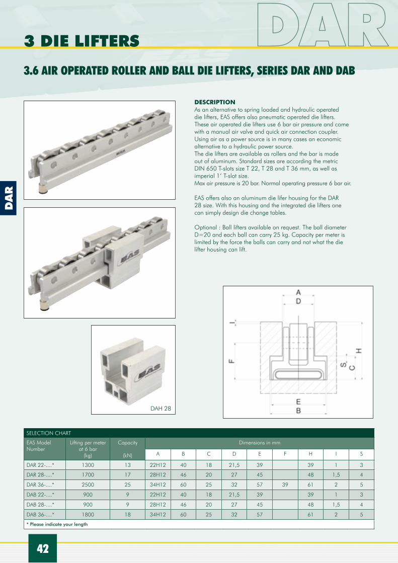
SELECTION CHART
EAS Model Number
Lifting per meterat 6 bar
(kg)
Capacity
(kN)
Dimensions in mm
A B C D E F H I S
DAR 22-....* 1300 13 22H12 40 18 21,5 39 39 1 3
DAR 28-....* 1700 17 28H12 46 20 27 45 48 1,5 4
DAR 36-....* 2500 25 34H12 60 25 32 57 39 61 2 5
DAB 22-....* 900 9 22H12 40 18 21,5 39 39 1 3
DAB 28-....* 900 9 28H12 46 20 27 45 48 1,5 4
DAB 36-....* 1800 18 34H12 60 25 32 57 61 2 5
* Please indicate your length
DESCRIPTIONAs an alternative to spring loaded and hydraulic operated die lifters, EAS offers also pneumatic operated die lifters. These air operated die lifters use 6 bar air pressure and come with a manual air valve and quick air connection coupler.Using air as a power source is in many cases an economic alternative to a hydraulic power source.The die lifters are available as rollers and the bar is made out of aluminum. Standard sizes are according the metric DIN 650 T-slots size T 22, T 28 and T 36 mm, as well as imperial 1’ T-slot size. Max air pressure is 20 bar. Normal operating pressure 6 bar air.
EAS offers also an aluminum die lifer housing for the DAR 28 size. With this housing and the integrated die lifters one can simply design die change tables.
Optional : Ball lifters available on request. The ball diameter D=20 and each ball can carry 25 kg. Capacity per meter is limited by the force the balls can carry and not what the die lifter housing can lift.
3.6 AIR OPERATED ROLLER AND BALL DIE LIFTERS, SERIES DAR AND DAB
3 DIE LIFTERS

DA
R +
DA
B
43
DAH 28
Ordering code die lifters: DAR A-B / DAB A-B
DAR = Die lifter Air with RollersDAB = Die lifter Air with BallsA = T-slot size 22, 28 or 36 for the metric sizes and 1 for 1” imperial sizeB = length of the die lifter in mm
Example DAR 28-600 is a die lifter for T-slot size 28 mm and with length of 600 mm. Lifting capacity is 0,6 x 1700 kg = 1020 kg or 10,2 kN
Ordering code housing (die lifter not included and need to be ordered separately).
Ordering Code Example: DAH 28-1200 is the housing for the DAR 28 or DAB 28 die lifter with a length of 1200 mm.

P141/P
ATG
44
4.1 MANUAL OPERATED, THE P141
4 PUMP UNITS AND CONTROLS
This hand pump can be used to pressurize single acting hydraulic cylinders but is mostly used for hydraulic die lifters in case these are use as only QDC item without any cylinders.The max. hydraulic pressure can be adjusted and set at the right operating pressure. The oil volume per stroke is 0,9 cm3 and the reservoir is 327 cm3.
4.2 AIR OPERATED PUMP UNIT, THE PATG 3102PB
This compact, lightweight air driven power source is very suitable for hydraulic die lifters only as it can be activated by foot or manually.Operates at 1,7 till 8,7 bar air pressure and delivers 3,0 l/min hydraulic flow till 350 bar and at 7 bar air pressure.
Selected or designed specifically for Quick Die Change applications EAS offers different kind of power packages.Depending on what kind of application and cylinders, double acting or single acting you have selected and if hydraulic die lifters are part or no part of your system, you can select different types of pump units.EAS offers a simple hand operated pump, air operated pumps as well as electric operated pump units complete with controls and valve packages.
Air hydraulic pump unit for max 250 bar hydraulic pressure for usage with die lifters . Model number EAHP-1
EPA
45
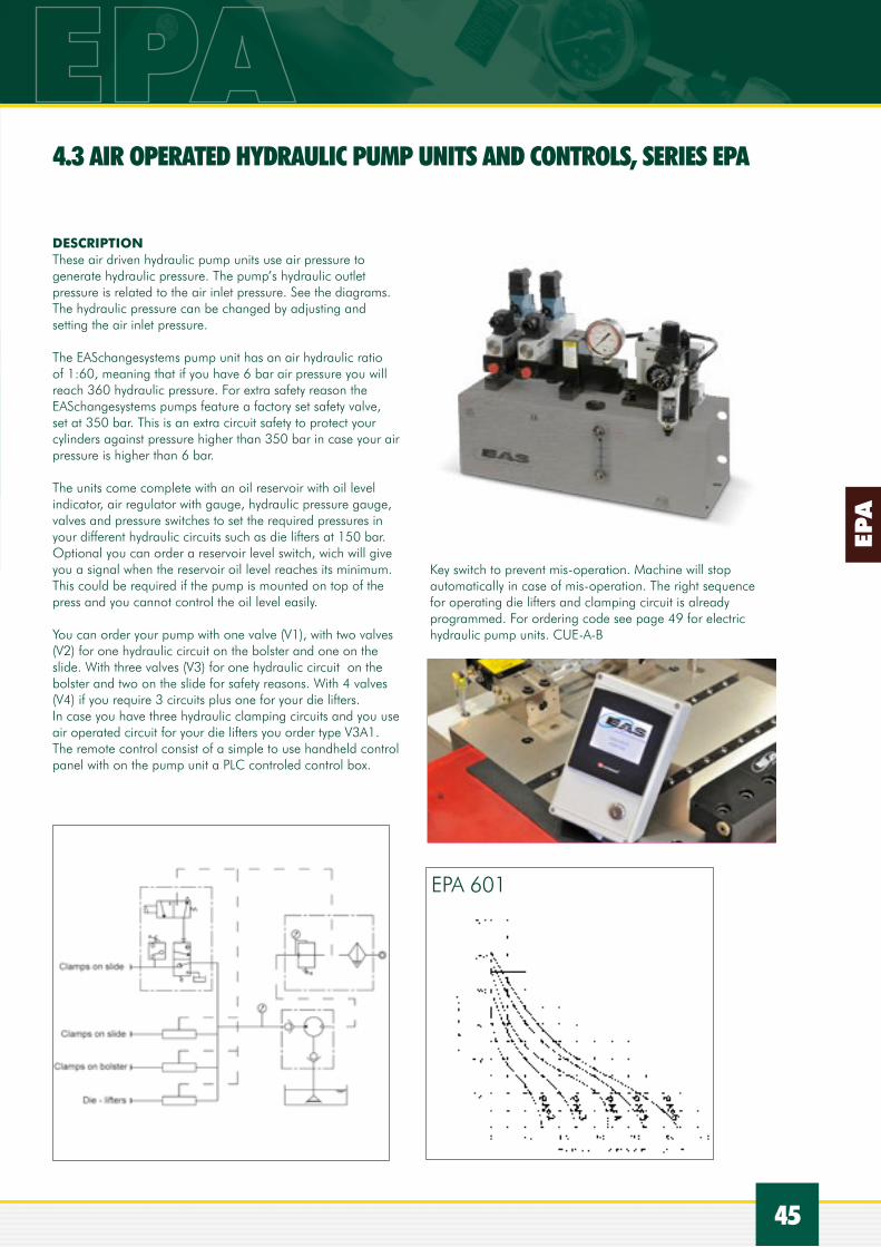
Key switch to prevent mis-operation. Machine will stop automatically in case of mis-operation. The right sequence for operating die lifters and clamping circuit is already programmed. For ordering code see page 49 for electric hydraulic pump units. CUE-A-B
EPA 601
DESCRIPTIONThese air driven hydraulic pump units use air pressure to generate hydraulic pressure. The pump’s hydraulic outlet pressure is related to the air inlet pressure. See the diagrams.The hydraulic pressure can be changed by adjusting and setting the air inlet pressure.
The EASchangesystems pump unit has an air hydraulic ratio of 1:60, meaning that if you have 6 bar air pressure you will reach 360 hydraulic pressure. For extra safety reason the EASchangesystems pumps feature a factory set safety valve, set at 350 bar. This is an extra circuit safety to protect your cylinders against pressure higher than 350 bar in case your air pressure is higher than 6 bar.
The units come complete with an oil reservoir with oil level indicator, air regulator with gauge, hydraulic pressure gauge, valves and pressure switches to set the required pressures in your different hydraulic circuits such as die lifters at 150 bar.Optional you can order a reservoir level switch, wich will give you a signal when the reservoir oil level reaches its minimum. This could be required if the pump is mounted on top of the press and you cannot control the oil level easily.
You can order your pump with one valve (V1), with two valves (V2) for one hydraulic circuit on the bolster and one on the slide. With three valves (V3) for one hydraulic circuit on the bolster and two on the slide for safety reasons. With 4 valves (V4) if you require 3 circuits plus one for your die lifters.In case you have three hydraulic clamping circuits and you use air operated circuit for your die lifters you order type V3A1.The remote control consist of a simple to use handheld control panel with on the pump unit a PLC controled control box.
4.3 AIR OPERATED HYDRAULIC PUMP UNITS AND CONTROLS, SERIES EPA

ECU
46
SELECTION CHART
EAS Model Number
Max hydraulic pressure(bar*)
Flow
(l/min)
Reservoirsize(L)
Qauntityvalves
Dimensions in mm
L1 L2 H H1 H2 D1 D2
EPA 601 V1 350 1,2 10 1 590 563 380 150 80 12 150
* at 6 bar air pressure
4 PUMP UNITS AND CONTROLS
OPERATIONAL PANEL TYPE CUE-A-B (SEE PAGE 49)
SYSTEM SETUP EXAMPLES
T-slot mounted single acting rocker clamps ERC, hollow rams ECA or MHC or T-slot clamps MTC with split safety circuit on the upper bed and one circuit on the lower press bed and one circuit for the single acting die lifters.
For usage on single acting cylinders and to protect the system against hose leackage and still keep the cylinders under pressure EAS offers a double hydraulic check valve type EDCV-1 to which 2 single acting hydraulic circuits can be connected.Ask EAS for dimensions and details.
4.4 DOUBLE HYDRAULIC CHECK VALVE TYPE EDCV-1
Ordering code: EPA 601-V1-A1-0
V1 = with 1 valve, V2= 2 valves, V3=3 valves, V4=4 valvesA1 = +1 adiotionel air valves for air operated die lifters0 =voltage solanoid with 0=DC 24V, 1=110V, 2=230VOrdering code example: EPA 601-V3-0 is an EAS Air Pump with 60:1 ratio with 3 valves and 24V DC for the valves.

EPE
47
Standard range can be selected with the following ordering code.
Ordering code: EPE-A-B-C-D
EPE = EAS Pump ElectricA: is for the flow range: 2 = 2 l/min , 4 = 4l/min.B: is for the pressure range 25 = 250 bar max. hydraulic pressure, 35 = 350 bar max hydraulic pressureC: is the amount of valves 2 = 2 valves, 3 = 3 valvesD: voltage 1 = 110V , 2 = 220V, 4 = 400V
The suitable control unit can be ordered with the following
ordering code CUE-A-B
CUE = Control Unit EASA = is the amount of circuits requires;20 = for 2 double acting cylinder circuits 21 = for 2 double acting circuits and 1 die lifter circuit.30 = 2 single acting circuits on the upper bed and 1 on the lower bed for single acting cylinders31 = 2 single acting circuits on the upper bed and 1 on the lower bed for single acting cylinders and 1 die lifter circuit.40 = special on requestB = for which area:E = EuropeU = USAA = Asia
4.5 ELECTRIC HYDRAULIC PUMP UNITS SERIES EPE AND CONTROLS
Hydraulic scheme for 2 circuits of double acting MOD cylinders with pressure switches. For example EPE 2-25-3-4 is an electric pump unit with 2 l/min at 250 bar max., with 3 valves and for 400 Volt.

EPE
48
4 PUMP UNITS AND CONTROLS
Hydraulic scheme for 2 circuits of double acting MOD cylinders with pressure switches as well as a set of die lifters with also a pressure switch. Pressure switches will switch off the pump if the required pressure is set. Controls are designed in such a way that in case die lifters are used the lower bed clamps can not be pressurized before the die lifters are released.
Hydraulic scheme for 2 circuits of single acting cylinders.
Hydraulic scheme for 2 circuits of single acting cylinders and a circuit for die lifters.

49
Complete die change systems are much more than only clamping and die lifters solutions. These improve the securing of the dies. However it does little to the overall die change over time. Comprehensive die change systems do not only reduce down time drastically but are also safer, give more control over the die movements and reduce labor cost.The advantages are many.The right chose is however very important. Factors which must be considered choosing the right die changing system are:
• Available budget and wanted results• Frequency of die changes• Amount, size and weight of dies involved• Number of presses and press type• Degree of automation• Floor space and floor conditions• Press shut height• Die storage location• Crane or forklift availability• Safety aspects
Each system offers different advantages.On the next pages you will find different solutions, from a simple pre roller system towards a almost full automatic factory with advanced die change systems.EAS offers you the expertise, the different solutions for YOUR needs, with experienced people all over the world.
EAS offers the following wide range of die carts:• Manual for small dies up to 1 Ton( 10 kN)• Electric driven carts up to 40 Ton (400 kN)• Rail guided carts up 100 Ton (1000 kN)• Air floating carts up to 125 Ton (1250 kN)
Either suitable for 1 or 2 dies, fixed or adjustable height, die movement towards one or both sides of the cart and manual, semi automatic or full automatic operation.
5 DIE HANDLING SYSTEMS

50
PR
DESCRIPTIONThe pre rollers make it very simple to pull out or to push in a die.It also allows the use of a fork lift truck or crane to remove and load the die. Die stoppers at the end of the pre roller will prevent the die from rolling off, but also allows easy loading of the die on the pre rollers. The mounted hook allows the pre roller to be removed from the press if necessary. It also allows the usage of one set of pre rollers for several presses by applying several sets of hooks.
Swivel models type PRS are fixed mounted pre rollers which can be turned away and stored along the press bed. Long pre rollers do feature a roller support in order to carry safely the load over the required distance. On request EAS provide powered rollers as well and other options. Mounting instructions are available from your EAS source.
5.1 PRE ROLLERS, THE EAS DIE LOADING ARMS SERIES PR AND PR….S
5 DIE HANDLING SYSTEMS

51
PR
Mounting information: ask EASchangesystems
SELECTION CHART
EAS Model Numberincluding 2 pre rollers and 2 mounting blocks
Individual EAS Model Number
of 2 mounting
blocks
Caryingper 2 set pre rollers
Capacity
Length
mm
Height
kg kN
Type PR
mm
Type PR..S
mm
PR 5-500 PRMB 500 500 5 500 200 200
PR 5-800 PRMB 500 500 5 800 200 200
PR 5-1000 PRMB 500 500 5 1000 200 200
PR 10-500 PRMB 1000 1000 10 500 200 200
PR 10-800 PRMB 1000 1000 10 800 200 200
PR 10-1000 PRMB 1000 1000 10 1000 200 200
PR 20-800 PRMB 2000 2000 20 800 250 320
PR 20-1000 PRMB 2000 2000 20 1000 250 320
PR 20-1250 PRMB 2000 2000 20 1250 250 320
PR 30-1000 PRMB 3000 3000 30 1000 400 420
PR 30-1250 PRMB 3000 3000 30 1250 400 420
PR 40-1000 PRMB 4000 4000 40 1000 400 420
PR 40-1250 PRMB 4000 4000 40 1250 400 420
PR 60-1300 PRMB 6000 6000 60 1300 on req. n.a.
PR 60-1600 PRMB 6000 6000 60 1600 on req. n.a.
PR 60-2000 PRMB 6000 6000 60 2000 on req. n.a.
PR 70-1450 PRMB 7000 7000 70 1450 on req. n.a.
PR 80-1200 PRMB 8000 8000 80 1200 on req. n.a.
PR 80-1600 PRMB 8000 8000 80 1600 on req. n.a.
PR 80-2000 PRMB 8000 8000 80 2000 on req. n.a.
PR 100-2000 PRMB 10000 10000 100 2000 on req. n.a.
Other capacity and length on request.
Double switch versions on request
PR
PR...S

52
5 DIE HANDLING SYSTEMS
Transfering the die into the press can be done manually or must be powered depending on the weight of the die. When the die is light enough, manual transfer is practical and economic. EAS offers the following solutions
A manual car is used to transport the dies from the storage area directly to the presses.
The adjustable height feature uses a hydraulic foot pump and cylinder to raise and lower the bed. The car can accommodate one 0,8 ton or two 0,5 ton dies. When the car arrives at the press it is positioned to allow the existing die to be manually pulled out of the press. To support the die between the cart and the press a set of bridge rollers can be added .Once the die has been removed the car is then positioned to allow the new die to be manually pushed into the press. The bridge rollers are then raised up out of the way and the die is transported back to the storage area.
EAS can offer different solutions depending on the die size and space limitations. Carts can be configured for side load or end load operation depending on the plant layout.Both configurations speed up the die change process.
5.2 DIE CHANGE CARS
5.2.1 MANUAL DIE CHANGE CARS

53
5.2.2 ELECTRIC DRIVEN DIE CHANGE CARS
When the dies are too heavy to be transported manually, a battery powered car with hand controls can be the solution. These carts can be equipped with variable height roller decks to accommodate different size of presses and storage systems levels.
Manual or powered push-pull mechanisms are available to transfer the dies in and out of the machine or storage systems. These powered transfer mechanism can be operated electrically or with air.
Die locks keep the die from moving on the roller deck when the car is in motion. These cars handle one or two dies with a combined weight of 40 ton and come equipped with a battery charging system.
A two station die change car can complete a die change in less than 5 minutes when used in combination of the EAS die lifters and clamps.
For smaller die sizes and weight the EAS TUGunit might be a cost effective solution. These Tugunits are used for transport purposes as shown on picture but can also be used to transport and position a die change car or table. Available in three sizes with different power drives and they can be equipped with a hydraulic unit to lift as well the car or table.
Electric driven car for a 10 ton die with chain driven push pull device.
Tag unit

54
5 DIE HANDLING SYSTEMS
A further step towards automation is the installation of a rail car system to serve one or more presses or a complete stamping line of presses.
This usually means a complete reorganization of the plant and is most often done in new plants. The die change car transports the dies to and from the storage. The car can be battery powered or by a cable trolley in the floor or by an overhead power rail; in most cases the option is determined by the rail length and the frequency of die change over.The cars are equipped with positioning devices for exact positioning in front of the press or at the storage rack.Economy versions are equipped with a spindle push/pull device while the more advanced cars are equipped with telescopic push pull devices with automatic grippers.
For safety purposes, each die roller bed is equipped with a die lock, which holds the die on the car during transport along the presses. Safety bumpers, acoustic or light signals can be part of the car. They can be operated manually, semi automatic or completely automatic.The operator can either walk along with the car or drive on the car on an operator platform.Loading and unloading of the dies can be done by an overhead crane.
5.2.3 RAIL GUIDED DIE CHANGE CARS
1 x 18 ton die change car on rails.

55
This rail guided car carries two dies each 10 ton weight and changes the dies with a telescopic push pull device which travels underneath the die. The angle shaped guides on the car are for loading the dies with an overhead crane. Large safety bumper on each side of the car and rails in the floor with a power cable with trolley also in the floor. In this way a fork lift truck can drive over the rails as well. Clamping system in the press is a double T-slot clamp system with rollers and in the upper bed are the EAS MTR cylinders built in.
Another example of a two stage die car with 2 x 10 ton dies, safety bumpers and telescopic push pull device to one side of the car.
56
5 DIE HANDLING SYSTEMS
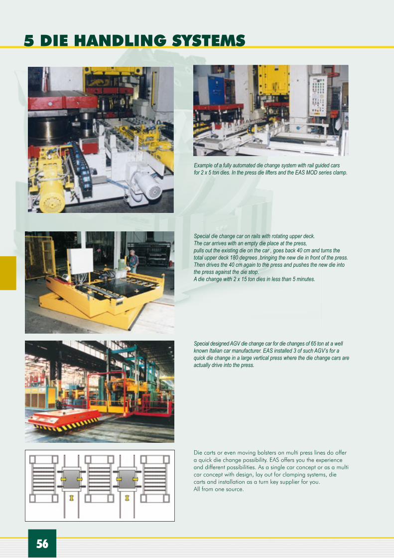
Special die change car on rails with rotating upper deck. The car arrives with an empty die place at the press, pulls out the existing die on the car , goes back 40 cm and turns the total upper deck 180 degrees ,bringing the new die in front of the press. Then drives the 40 cm again to the press and pushes the new die into the press against the die stop.A die change with 2 x 15 ton dies in less than 5 minutes.
Special designed AGV die change car for die changes of 65 ton at a well known Italian car manufacturer. EAS installed 3 of such AGV’s for a quick die change in a large vertical press where the die change cars are actually drive into the press.
Die carts or even moving bolsters on multi press lines do offer a quick die change possibility. EAS offers you the experience and different possibilities. As a single car concept or as a multi car concept with design, lay out for clamping systems, die carts and installation as a turn key supplier for you. All from one source.
Example of a fully automated die change system with rail guided cars for 2 x 5 ton dies. In the press die lifters and the EAS MOD series clamp.

57
5.3 DIE CHANGE TABLESSingle or double station die change tables are dedicated to one press. These tables can use manual or powered transfer mechanism depending on the mould weight to load and unload the press. The powered transfer can be equipped with an automatic push button control.
When using a single station die change table you must first pull the die from the press and remove it from the table by overhead crane or fork lift truck. The new die is then positioned on the table roller deck. The new die is then pushed into the press. These tables are used in conjunction with clamp and die lifter systems in the press.
The picture shows a simple manual two station die change table. On the frame we have mounted our aluminum housing DAH 28 with the air operated die lifters DAR 28. The middle section can be moved a side in order to allow the operator to push the die into the press and to have access to the press.Left or right is space to have the new die already waiting to be brought in. Another idea from EAS as IdEAS come from EAS.
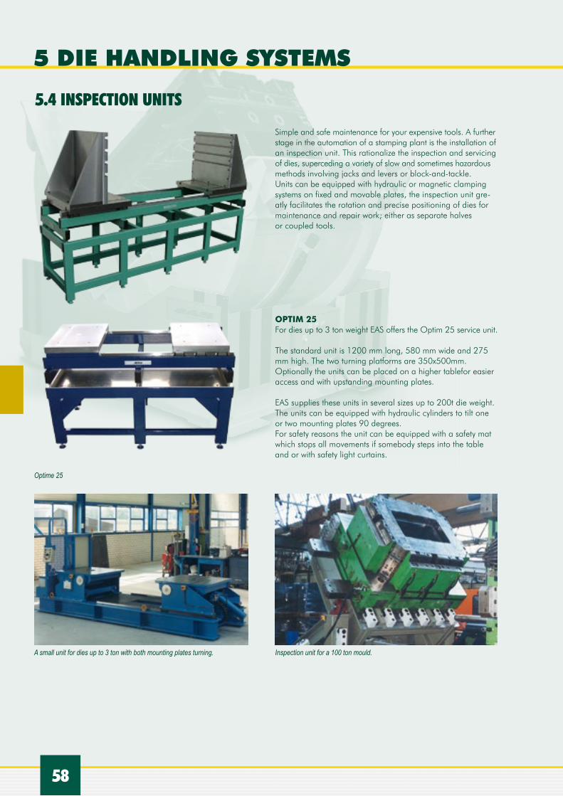
Die inspection and transportation unit for the maintenance department equipped with simple magnetic clamping system to clamp the die.
5.2.4 AIR FLOATING DIE CHANGE CARS
Air float cars actually float on a thin air film like a hovercraft, which provides great mobility in restricted areas. They can also carry very heavy loads without special floor reinforcement.
It can be an interesting alternative to rail guided die change cars. However the floor must be horizontal, cracks filled, be sealed to perform in the best way. Many press shops do not feature such floor conditions.Air powered drive wheels control the speed and direction of the cart while the cart is moving.
Ask EAS for the possibilities in your factory.
58
5 DIE HANDLING SYSTEMS
Simple and safe maintenance for your expensive tools. A further stage in the automation of a stamping plant is the installation of an inspection unit. This rationalize the inspection and servicing of dies, superceding a variety of slow and sometimes hazardous methods involving jacks and levers or block-and-tackle. Units can be equipped with hydraulic or magnetic clamping systems on fixed and movable plates, the inspection unit gre-atly facilitates the rotation and precise positioning of dies for maintenance and repair work; either as separate halves or coupled tools.
OPTIM 25For dies up to 3 ton weight EAS offers the Optim 25 service unit.
The standard unit is 1200 mm long, 580 mm wide and 275 mm high. The two turning platforms are 350x500mm. Optionally the units can be placed on a higher tablefor easier access and with upstanding mounting plates.
EAS supplies these units in several sizes up to 200t die weight. The units can be equipped with hydraulic cylinders to tilt one or two mounting plates 90 degrees.For safety reasons the unit can be equipped with a safety mat which stops all movements if somebody steps into the table and or with safety light curtains.
5.4 INSPECTION UNITS
A small unit for dies up to 3 ton with both mounting plates turning. Inspection unit for a 100 ton mould.
Optime 25

59
The die splitters or die separator makes it possible to split and open the die, turn one die half and bring the turned die half again on the table. One person can there for split and service a die set in a safe, controlled and repeatable way. EAS delivers these die splitters from a die weight of 2 ton up till 60 ton.
5.5 DIE SPLITTER, DIE SEPARATOR
Another example of a die splitter.
A 15 ton die can be easily splitted.
The upper half is lowered and moved outside for easy access and maintenance.

60
5 DIE HANDLING SYSTEMS
5.6 DIE TILTING UNITS, DIE ROTATORS
SELECTION CHART
EAS Model Number
Max. weight(ton)
Time/90º
(sec)
Motor
(kW)
Dimensions in mm Machine Weight
(kg)A B C D E F G
EMS 30 3 24 0.75 900 900 516 1416 1250 900 350 780
EMS 50 5 20 1.5 1050 1050 564 1614 1550 1050 481 1160
EMS 80 8 26 1.5 1300 1050 631 1931 1700 1050 481 1400
EMS 100 10 26 2.2 1300 1300 631 1931 1700 1300 481 1550
EMS 150 15 35 3.7 1550 1550 848 2398 2350 1550 560 3250
EMS 200 20 40 3.7 1800 1800 915 2715 2500 1800 600 5100
EMS 300 30 43 5.5 2000 2000 919 2919 3460 2000 850 6900
EMS 400 40 54 3.7 x 1 2200 2200 1178 3378 3500 2200 850 10000
EMS 500 50 54 5.5 x 2 2400 2400 1232 3632 4100 2350 900 13000
EAS die rotator type EMSDespite their high value, the turning and opening of expensive dies and moulds is still often done by means of an overhead crane. This is dangerous work for the operator and the risk of damaging the expensive tools is high. Using the EAS die rotators one operator can easily and safely rotate the die on his own.Two models are available, a floor standing model type EMS and one that is on level floor type EFT, which takes up less space and allows, for example, fork lift trucks to drive over the unit if not in use.
For more information please consult your EAS partner. Available for 3 ton dies up to 50 ton dies.

61
5.7 DIE STORAGE SYSTEMSThis electric driven die change car for a large vertical press can bring the dies far away from the press to a special die storage area. The dies can be stored left and right of the electric driven car. The driver has a camera and a monitor for exact positioning the car into the press. Changing and store dies between 10 and 20 ton is in this way simple, fast and safe.

62
6 COUPLERS
For hydraulic connections EAS deliver the following range of couplers:
< EIRF/M series Quick release, non spill, flat face hydraulic manual coupler, suitable for 210 till 300 bar (3000 till 4200 psi) pressure (depends on the model) and suitable for 30 l/min. till 1000 l/min. flow. Available in 7 different sizes from size 7 mm until size 30 mm.
6.1 MONO COUPLERS
With manual multi couplers one can connect several fluid circuits, such as hydraulic, air and electric circuits fast and without making mistakes of wrong connections.A simple parking station is provided to ‘park’ the press side multi coupler during a die change, avoiding coupler damage or dirt entering the circuits.
EAS Quick Connect Manual Multi Couplers greatly reduce set-up times. Available with different amount of couplers and coupler sizes for air, water and hydraulic connections. Ask for our EAS coupler catalogue for all the different possibilities or ask your EAS contact.
6.2 MANUAL MULTI COUPLERS
QUICK RELEASE FLAT FACE HUDRAULIC COUPLER
EAS Model Number
Max. flowl/min
DIN
mm
Max. workpressure
(bar)
Burst press. coupled
(bar)
Dimensions in mm
B D L L2 L1 SW1 SW2
EIR F/M 14 30 7 300 1200 28 1/4” 85,5 48,0 48,0 22 22
EIR F/M 38 50 9 210 1000 32 3/8” 108,5 60,0 64,5 27 24
EIR F/M 12 50 9 210 1000 32 1/2” 116,5 95,0 62,5 27 27
EIR F/M 34 200 15 210 1000 42 3/4” 132,0 78,0 79,0 36 36
EIR F/M 100 250 17 210 850 48 1” 154,0 82,5 92,5 45 45
EIR F/M 114 350 21 210 850 55 11/4” 173,0 90,0 105,5 55 55
EIR F/M 112 1000 30 200 700 80 11/2” 215,0 111,0 152,5 65 70

63
6.3 AUTOMATIC MULTI COUPLERS
The EAS self-locking and swimming multi coupler design can be used in a wide range of industrial application to connect water, air, gas, steam, hydraulic and electric connections in a simple and quick way. Application fields are for example automotive, test benches, machine building, plastic injection moulding industry, die-casting and off shore applications. In order to design and apply the right solution we need to discuss with you the following:• what fluid or gas need to be connected• pressure range• temperature• flow requirements• open or closed couplers• leak-proof or not• connecting threads• how many connections• voltage and amperage for electric connections-amount of cycles and cycle time• environment conditions• size limitations.
With all this, most applications require a special multi coupler, which can be very small up to very large with many mono couplers or for a long stroke.
With the EAS automatic multi couplers you achieve thefollowing advantages:
• Time saving, while you connect in the same time in a few seconds all fluid and electric connections.• Safety increase. No wrong connections can be made any more as the multi couplers can only be connected in one way, connection and disconnecting is automatic, cleanbreak connections to avoid spillage of fluid also at higher temperature.• High quality products with minor maintenance, resulting in a long trouble free life.• Long experience in the coupler technology with on going research and development.• Productivity increase while long lasting down times will be reduced to a few seconds to connect all your utility connections automatically.

IDEAS EASCOME FROM
EASchangesystems supplies automatic multi couplers on movable bolsters for connecting electricity, pneumatic and hydraulic connections
64
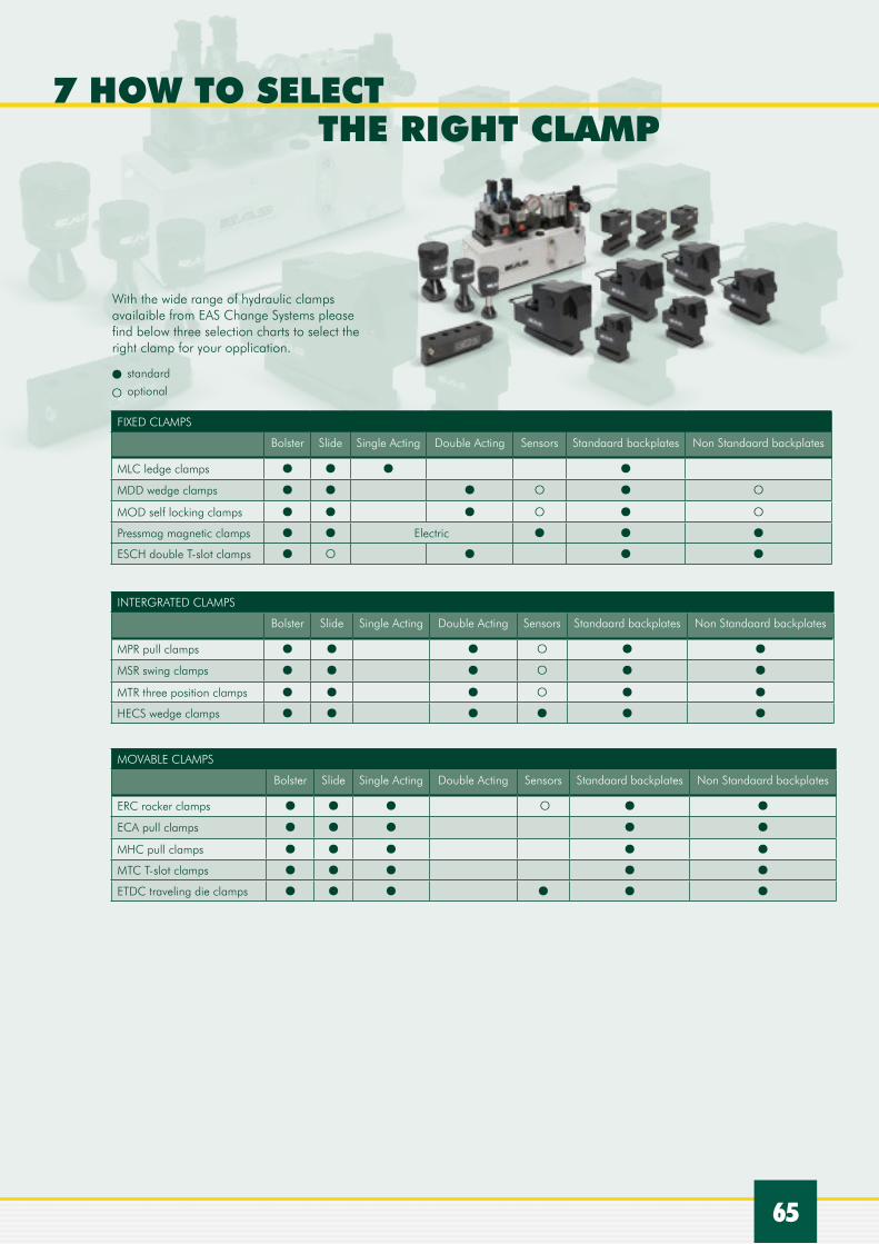
65
With the wide range of hydraulic clamps availaible from EAS Change Systems please find below three selection charts to select the right clamp for your opplication.
7 HOW TO SELECT THE RIGHT CLAMP
FIXED CLAMPS
Bolster Slide Single Acting Double Acting Sensors Standaard backplates Non Standaard backplates
MLC ledge clamps
MDD wedge clamps
MOD self locking clamps
Pressmag magnetic clamps Electric
ESCH double T-slot clamps
INTERGRATED CLAMPS
Bolster Slide Single Acting Double Acting Sensors Standaard backplates Non Standaard backplates
MPR pull clamps
MSR swing clamps
MTR three position clamps
HECS wedge clamps
MOVABLE CLAMPS
Bolster Slide Single Acting Double Acting Sensors Standaard backplates Non Standaard backplates
ERC rocker clamps
ECA pull clamps
MHC pull clamps
MTC T-slot clamps
ETDC traveling die clamps
standard
optional

UK
www.EASchangesystems.com
No change, no progress
Quick mold change solutions
66
UK
www.EASchangesystems.com
Time is money
Magnetic clamping solutions
Time is money
8 OTHER EAS PRODUCTS AND SOLUTIONS
EAS Quick Mould Change systems (QMC)
EAS offers a wide product portfolio for a quick mould change on injection moulding machines and blow moulding machines.This QMC product line offers mechanical, hydraulic and magnetic clamping solutions for machines up to 6000 ton, ejector couplers, couplers systems for all utility connections, mould handling and maintenance equipment.From a simple mono coupler towards a complete automated factory, all solutions from one international source.
EAS magnetic clamping solutions (MCS)
EAS also offers permanent magnetic clamping solutions for the fast and reliable clamping of moulds, dies and tools on injection moulding machines, die casting machines and stamping presses.

IDEAS EASCOME FROM
67
ALL SOLUTIONS FOR THEAUTOMOTIVE INDUSTRYAnother example of a total solution project was for an Italian automotive supplier for a complete automated system for one of their factories in Spain. For two large 2700 t Italtech injection moulding machines, EAS designed, manufactured, co-ordinated and installed the following complete QMC system.The injection moulding machines were equipped with a hydraulic clamping system and rollers for horizontal loading of the 50 t moulds, as well as with automatic multi coupler systems for a quick and leakproof connection of all utility connections.
A rail-guided mould change car carrying 2 moulds of max. 50 t was installed, as well as the rails for this car and the power supply. Nine mould storage systems are installed on the other side of the guide car rails, including an automatic preheating station to automatically preheat the mould that is going into the machine. This also saves hours by doing this outside the machine instead of when the mould is on the machine.
The rail-guided mould change car for two moulds of max 50 t. This car can be operated by means of a remote control unit and is equipped with steps for easy access to the top of the car, as well as safety bumpers.
On the other side of the rail guide car are 9 mould storage systems, on which the moulds are stored using the mould change car.
Each mould has standardized backplates and is equipped with standard automatic multi coupler plates on which water, hydraulic and electrical connections are gathered.
The storage systems also include a preheating station, which is shown here during the installation period.
Each machine is equipped with self-locking adaptive hydraulic clamping and rollers for quick and easy horizontal loading and clamping of the moulds.

EASE1518
06/U
K-QDCc
atUK2
015
UK51
02Q
DC
Europe/The NetherlandsEAS Europe B.V.De Hooge Hoek 19A / 3927 GG Renswoudephone: +31 318 477 010 / The [email protected]
USAEAS Mold & Die Change System, Inc.N50 W13740 Overview Dr Suite F / Menomonee Falls, WI 53051PO Box 1614 / Milwaukee WI 53201 phone: +1 262 783 7955 / United States of [email protected]
FranceEAS France S.A.R.L.604, Voie Galilée / ZI Alpespace73800 Sainte Hélène-du-Lacphone: +33 4 79 65 04 10 / [email protected]
ChinaSuzhou EAS Mold & Die Change Systems Co. Ltd.No.1188 Pangjin Road / Wujiang City / 215200phone: +86 51 26 30 91 / PR [email protected]
ItalyEAS MED S.r.L.Via J. F. Kennedy, 19/C2 / 20871 Vimercate (MB) phone: +39 039 608 3816 / [email protected]
www.EASchangesystems.com