TIME HISTORY ANALYSIS OF INTZE WATER TANK ... practice in the design of Overhead Intze water tank....
6
International Research Journal of Engineering and Technology (IRJET) e-ISSN: 2395-0056 Volume: 04 Issue: 08 | Aug -2017 www.irjet.net p-ISSN: 2395-0072 © 2017, IRJET | Impact Factor value: 5.181 | ISO 9001:2008 Certified Journal | Page 1595 TIME HISTORY ANALYSIS OF INTZE WATER TANK THROUGH AN USER FRIENDLY PROGRAM DEVELOPED BY VISUAL BASIC AND BY SAP Manohar B 1 , Kashinath B Rugi 2 1 PG student, Dept. of Civil Engineering, Government Engineering College, Haveri, Karnataka, India 2 Asst.Prof. Dept. of Civil Engineering, Government Engineering College, Haveri, Karnataka, India ---------------------------------------------------------------------***--------------------------------------------------------------------- Abstract – This project presents a critical review of the current practice in the design of Overhead Intze water tank. 0The design is based on IS: 3370-1965 design code for water retaining structures. The program is written by employing powerful window complaint Visual Basic 6.0 programming language. User friendly program is developed for the design of water tank which will have provision for the user to choose tank capacity, grade of concrete and steel, unit weight of material etc. The tank is designed to resist stresses as per IS: 3370(Part II) - 1965, seismic design as per IS: 1893-2002. The program will provide default values like height of staging, bracing interval, diameter of cylindrical tank etc. Due to fluid structure interactions, the seismic behaviour of elevated tanks has characteristics of complex phenomena. The main aim of the study is to understand the behaviour of the supporting system with SAP software. Here two different supporting system with such as radial bracing and cross bracing are compared with basic supporting system for various fluid conditions and for different capacity. Tank responses including base shear, overturning moment, bending moment at bottom of column and story displacement has been observed, and then the results have been compared. Key Words: Intze water tank, visual basic, Radial bracing, cross bracing, Base shear, bending moment, displacement, Acceleration. Shear stress, normal stress, Time history. 1. INTRODUCTION The water tower will be essential structure supporting of a water tank constructed at an elevation suitable to drive of a water source system for a supply of potable water and to provide an emergency storage of fire protection. The word standpipe is used for exchangeable and it refers to a water tower, one with tall and another with narrow proportions especially in some places. 1.1 INTZE TANK The Intze guideline is a German word: Intze– Prinzip, these name provided to build different standards named after water powered engineer “Otto Intze (1843-1904)”, in one case the Intze standard identifies water tower and other case is requesting dam. The basic preference for this kind of tank is the inward radial thrust of the conical base to balance an outward radial thrust of the spherical lowest components. This can be discovered to store considerable amount of water for a raised spherical tank to provide flat floor slab expectations work out to a uneconomical configuration. The main principle of these floor slab turns into excessively thick to more tanks of diameter, it suits to best for Intze tank under this condition. An Intze tank basically made of top dome (roof), floor slab and the cylindrical shaped wall which may be a consolidation for base spherical dome and conical dome. Subjected to regulate compression, the thickness of conical floor slab considerably meet expectations and a chance to prove another economical flat slab floor. The proportions of base dome and conical dome are arranged to outward thrust with bottom domed and floor only balances the internal thrust because of conical dome. The diameter of lowest components of dome is preferably about 65 to 70% of the diameter of the tank. Incline of conical dome is in between 50 to 55 degree level according to consideration. The tank needs to support one staging that comprises an amount of columns to be spaced uniformly along the perimeter of base ring beam through these columns. Fig-1 Different components of Intze tank.
-
Upload
truongkien -
Category
Documents
-
view
240 -
download
2
Transcript of TIME HISTORY ANALYSIS OF INTZE WATER TANK ... practice in the design of Overhead Intze water tank....
International Research Journal of Engineering and Technology (IRJET) e-ISSN: 2395-0056
Volume: 04 Issue: 08 | Aug -2017 www.irjet.net p-ISSN: 2395-0072
© 2017, IRJET | Impact Factor value: 5.181 | ISO 9001:2008 Certified Journal | Page 1595
TIME HISTORY ANALYSIS OF INTZE WATER TANK THROUGH AN USER FRIENDLY PROGRAM DEVELOPED BY VISUAL BASIC AND BY SAP
Manohar B1, Kashinath B Rugi2
1PG student, Dept. of Civil Engineering, Government Engineering College, Haveri, Karnataka, India 2Asst.Prof. Dept. of Civil Engineering, Government Engineering College, Haveri, Karnataka, India
---------------------------------------------------------------------***---------------------------------------------------------------------Abstract – This project presents a critical review of the current practice in the design of Overhead Intze water tank. 0The design is based on IS: 3370-1965 design code for water retaining structures. The program is written by employing powerful window complaint Visual Basic 6.0 programming language. User friendly program is developed for the design of water tank which will have provision for the user to choose tank capacity, grade of concrete and steel, unit weight of material etc. The tank is designed to resist stresses as per IS: 3370(Part II) - 1965, seismic design as per IS: 1893-2002. The program will provide default values like height of staging, bracing interval, diameter of cylindrical tank etc. Due to fluid structure interactions, the seismic behaviour of elevated tanks has characteristics of complex phenomena. The main aim of the study is to understand the behaviour of the supporting system with SAP software. Here two different supporting system with such as radial bracing and cross bracing are compared with basic supporting system for various fluid conditions and for different capacity. Tank responses including base shear, overturning moment, bending moment at bottom of column and story displacement has been observed, and then the results have been compared.
Key Words: Intze water tank, visual basic, Radial bracing, cross bracing, Base shear, bending moment, displacement, Acceleration. Shear stress, normal stress, Time history. 1. INTRODUCTION
The water tower will be essential structure supporting
of a water tank constructed at an elevation suitable to drive of a water source system for a supply of potable water and to provide an emergency storage of fire protection. The word standpipe is used for exchangeable and it refers to a water tower, one with tall and another with narrow proportions especially in some places.
1.1 INTZE TANK The Intze guideline is a German word: Intze– Prinzip, these name provided to build different standards named after water powered engineer “Otto Intze (1843-1904)”, in one case the Intze standard identifies water tower and other case is requesting dam. The basic preference for this kind of tank is the inward radial thrust of the conical base to balance an
outward radial thrust of the spherical lowest components. This can be discovered to store considerable amount of water for a raised spherical tank to provide flat floor slab expectations work out to a uneconomical configuration. The main principle of these floor slab turns into excessively thick to more tanks of diameter, it suits to best for Intze tank under this condition. An Intze tank basically made of top dome (roof), floor slab and the cylindrical shaped wall which may be a consolidation for base spherical dome and conical dome. Subjected to regulate compression, the thickness of conical floor slab considerably meet expectations and a chance to prove another economical flat slab floor. The proportions of base dome and conical dome are arranged to outward thrust with bottom domed and floor only balances the internal thrust because of conical dome. The diameter of lowest components of dome is preferably about 65 to 70% of the diameter of the tank. Incline of conical dome is in between 50 to 55 degree level according to consideration. The tank needs to support one staging that comprises an amount of columns to be spaced uniformly along the perimeter of base ring beam through these columns.
Fig-1 Different components of Intze tank.

International Research Journal of Engineering and Technology (IRJET) e-ISSN: 2395-0056
Volume: 04 Issue: 08 | Aug -2017 www.irjet.net p-ISSN: 2395-0072
© 2017, IRJET | Impact Factor value: 5.181 | ISO 9001:2008 Certified Journal | Page 1596
1.2 Design procedure of Intze tank
Outline for top dome and top ring beam. Design of cylindrical wall. Design of ring beam at the intersection of cylindrical
shaped wall to conical dome. Design of conical dome and bottom spherical dome, Design of bottom ring beam. About staging i.e. the design of supporting structure, About foundation design. It is discovered that for storage of more capacity of water an elevated circular tank provide floor slab works out to an uneconomical design. It is mainly on account of the fact that the floor slab becomes too thick for large diameters tanks. Intze tank is best suitable under such circumstances. An Intze tank essentially consist of a top dome (roof), the cylindrical wall and the floor slab, which is a combination of conical dome and bottom spherical dome. Being subjected to direct compression the thickness of the domical floor, works out to be much less and hence it proves to be economical alternative to flat slab floor. The proportion of the conical dome and the bottom dome are so arranged that the outward thrust from the bottom domed part of the floor balances the inward thrust due to the conical domed part of the floor. The diameter of the bottom dome should preferably be about 65 to 70% of the diameter of the tank. From considerations of economy, the inclination of the conical dome should be between 50 to 55° with the horizontal.
1.3 INTRODUCTION TO VISUAL BASIC Fundamental VISUAL is a large amount of modifying programming language starting with the advanced earlier version of DOS form known as BASIC. BASIC means Beginners universally symbolic typical direction book code. It may be a generally not to take difficult modifying programming language. The code takes a look to considerable measure in English programming language. Various software organizations has been changed the typical forms for BASIC such as Microsoft’s QBASIC, QUICKBASIC, GWBASIC, IBM BASIC and so on. However, today individuals want to utilize fundamentals of Microsoft Visual Basic, similarly as it may be a great form of modifying programming language to support resources to help all around. Now, there exists plenty of VB forms exists in the market. The most prominent majority is still utilizes various VB programmers none other than VISUAL BASIC 6. Similarly likewise we need VB.NET, Visual Fundamental 2005, Visual Basic 2008 and the recent version is Visual Basic 2010. Both VB 2008 and VB 2010 are fully turned into object oriented programming language.
1.4 Need for the present study
The water tanks are visually simple but the analysis and design are difficult.
Generally there are shell type structures. These structure’s methods are involved in complicated analysis and design.
The membrane theory is employed for design of the elements of water tank. The membrane action will be occur in joints with the ring beams this may cause in local bending and this condition is more rigorous, which necessitates in the elaborate analysis, detail and design. An elevated water tanks involves considerable amount of water mass at the top a slender staging which are most critical respect for disappointment of tank through seismic activity.
The conventional design for liquid tank is mostly based on loading conditions; loading will be axi-symmetric load by wind and seismic loads. Most of the designs are based on it, it is more complicated to do hand computations.
2. OBJECTIVES
The main objective of the system is to develop a user friendly computer program for the design of water tank using Visual basic and SAP 2000. This system will have the provision to choose namely Tank capacity, Grade of concrete and steel, bearing capacity of soil, Unit weight of the material etc.
The tank dimensions obtained using Visual Basic Programming are taken in SAP and the model is analyzed for 3 different capacities like 500m3, 1000m3 and 1500m3 each capacity comprises of different loading cases.
Code from requesting act to concrete structures for those capacity for fluids IS 3370(part 3) shaft or staging variations, the tank dimensions obtained using Visual Basic Programming are taken in SAP and the model is analyzed for 3 different capacitieslike 500m3, 1000m3 and 1500m3 each capacity comprises of different loading cases such as:
Tank empty condition (Time -history analysis)., Tank full condition (Time-history analysis).,Tank half condition (Time-history analysis).,Zone 4.,Zone 5.,Simple bracing., Cross bracing., Radial bracing
Comparison of results for different models in terms of base shear, displacement, Acceleration. Shear stress, normal stress.
3. DESCRIPTION OF THE MODEL For consideration purpose, 3d Intze RCC overhead tank with typical capacities is taken. This design is taken for every analysis methods to join with Indian Standard Codes for practice. The water tank dome can be planned by working
International Research Journal of Engineering and Technology (IRJET) e-ISSN: 2395-0056
Volume: 04 Issue: 08 | Aug -2017 www.irjet.net p-ISSN: 2395-0072
© 2017, IRJET | Impact Factor value: 5.181 | ISO 9001:2008 Certified Journal | Page 1597
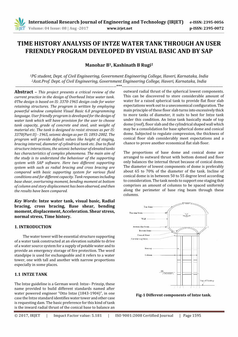
stress method, supporting columns and braces via limit state method
Table-1 Details of the specimen used for study of
structural behavior of Intze water tank.
3.1 Loads considered
Dead load (Floor finish) 1.0 kN/m2.
Imposed load 1.5 kN/m2
Zone factor (Z) 0.36 (Zone-5)
Importance factor (I) 1.0
Response reduction factor 5
Wind speed 33 m/s
Terrain category 2
Structural class B
Risk coefficient 1
3.2 Load combinations In addition load combinations are illustrated in IS 875- 1987(Part 5- Special loads and combinations) with title as “Code about act to design loads with buildings and structures”. Here, the factors are need to consider are,
1.5 (DL + IL) (DL +IL ± WL or EL) 1.5 (DL ± WL or EL)
Fig-2 Screen shot showing dimensions of the Intze Water Tank in VISUAL Basic
Fig-3 Intze water tank model with Radial bracing in SAP
GEOMETRY OF THE TANK AS PER VISUAL BASIC PROGRAM
Capacity of the Tank 500mᶟ 1000mᶟ 1500mᶟ
Unit Weight of Concrete 25kN/mᶟ 25kN/mᶟ 25kN/mᶟ
Thickness of Top Dome 0.1m 0.1m 0.1m
Rise of Top Dome 2m 2m 2m
Size of Top ring Beam 0.2m*0.2m 0.25m*0.52
m 0.25m*0.25
m
Diameter of Tank 10m 12m 16m
Height of Cylindrical wall
6m 8m 10m
Thickness of Cylindrical wall
0.25m 0.3m 0.4m
Rise of Conical Dome 2m 2.4m 3.2m
Thickness of Conical shell
0.2m 0.25m 0.3m
Rise of Bottom dome 1.25m 1.5m 2m
Thickness of Bottom dome shell
0.3m 0.4m 0.5m
Number of Columns 8 10 12
Number of Bracing level 3 3 4
Size of Bottom ring Beam
0.3m*0.2m 0.4m*0.6m 0.4m*0.6m
Distance between Intermediate bracing
3m 5m 4m
Height of staging above Foundation
12m 16m 20m
Diameter of Columns 0.5m 0.7m 0.8m
Size of Bracing 0.35m*0.35m 0.45m*0.45
m 0.5m*0.5m
International Research Journal of Engineering and Technology (IRJET) e-ISSN: 2395-0056
Volume: 04 Issue: 08 | Aug -2017 www.irjet.net p-ISSN: 2395-0072
© 2017, IRJET | Impact Factor value: 5.181 | ISO 9001:2008 Certified Journal | Page 1598
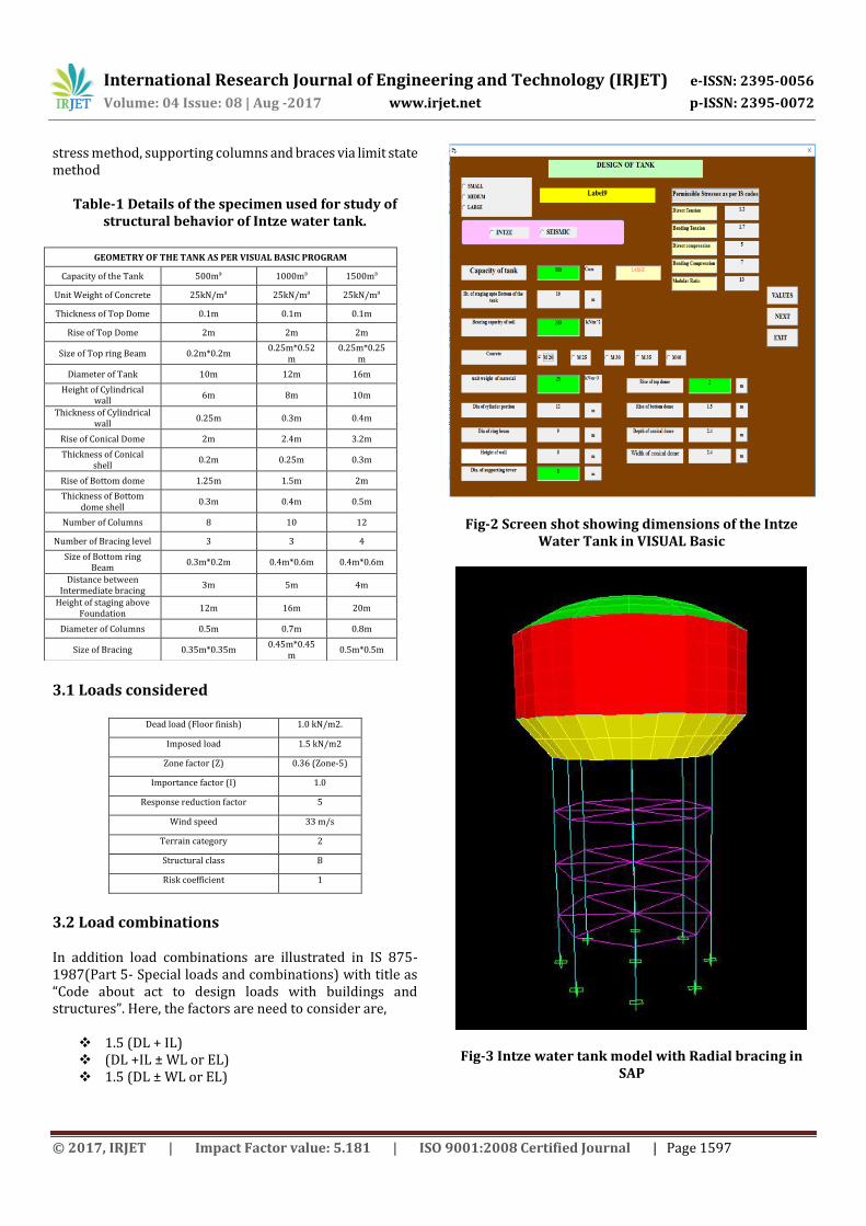
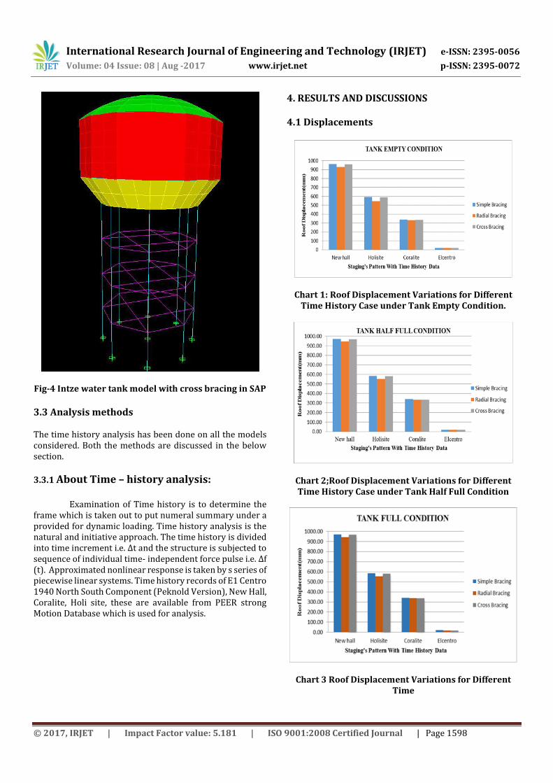
Fig-4 Intze water tank model with cross bracing in SAP
3.3 Analysis methods The time history analysis has been done on all the models considered. Both the methods are discussed in the below section.
3.3.1 About Time – history analysis: Examination of Time history is to determine the
frame which is taken out to put numeral summary under a provided for dynamic loading. Time history analysis is the natural and initiative approach. The time history is divided into time increment i.e. ∆t and the structure is subjected to sequence of individual time- independent force pulse i.e. ∆f (t). Approximated nonlinear response is taken by s series of piecewise linear systems. Time history records of E1 Centro 1940 North South Component (Peknold Version), New Hall, Coralite, Holi site, these are available from PEER strong Motion Database which is used for analysis.
4. RESULTS AND DISCUSSIONS 4.1 Displacements
Chart 1: Roof Displacement Variations for Different Time History Case under Tank Empty Condition.
Chart 2;Roof Displacement Variations for Different Time History Case under Tank Half Full Condition
Chart 3 Roof Displacement Variations for Different Time
International Research Journal of Engineering and Technology (IRJET) e-ISSN: 2395-0056
Volume: 04 Issue: 08 | Aug -2017 www.irjet.net p-ISSN: 2395-0072
© 2017, IRJET | Impact Factor value: 5.181 | ISO 9001:2008 Certified Journal | Page 1599
History Case under Tank Full Condition. Displacement is directly proportional to stiffness of the structure, displacements are practically rise to as seen in the chart 1, 2 and 3. The critical reaction happens in the case that of full tank Also now and then for void tank. This result might be expected to, the hydrodynamic pressure of container previously, half -full case as compared for the full filling case may be higher.
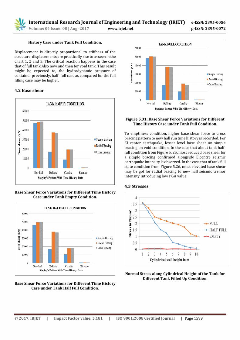
4.2 Base shear
Base Shear Force Variations for Different Time History Case under Tank Empty Condition.
Base Shear Force Variations for Different Time History Case under Tank Half Full Condition.
Figure 5.31: Base Shear Force Variations for Different Time History Case under Tank Full Condition.
To emptiness condition, higher base shear force to cross bracing pattern to new hall run time history is recorded. For EI center earthquake, lesser level base shear on simple bracing on void condition. In the case that about tank half-full condition from Figure 5. 25, most reduced base shear for a simple bracing confirmed alongside Elcentre seismic earthquake intensity is observed. In the case that of tank full state condition from Figure 5.26, most elevated base shear may be got for radial bracing to new hall seismic tremor intensity Introducing low PGA value.
4.3 Stresses
Normal Stress along Cylindrical Height of the Tank for Different Tank Filled Up Condition.

International Research Journal of Engineering and Technology (IRJET) e-ISSN: 2395-0056
Volume: 04 Issue: 08 | Aug -2017 www.irjet.net p-ISSN: 2395-0072
© 2017, IRJET | Impact Factor value: 5.181 | ISO 9001:2008 Certified Journal | Page 1600
Shear Stress along Cylindrical Height of the Tank for Different Tank Filled Up Condition.
From the above Figure s (Figure 5.32 and 5.3 it can be observed that, the stresses are within permissible limits of 5 N/mm2 in case of side wall, bottom dome and conical dome as per IS 456:2000. Normal Stress distribution along cylindrical wall is linear as seen from the Figure 5.27 above for tank full condition and half full condition and for empty condition the magnitude of stress is zero is recorded. For half full condition as we move towards top the magnitude of stress approaches to minimum value as compared to full.
5. CONCLUSIONS On the basis of the results obtained from time history analysis of tank with different staging configurations, following conclusion can be drawn. The major system replies as base shear and
displacement are highly scattered. This shows that the system is vastly influenced by the earthquake characteristics and particularly frequency content of earthquake records.
Radial type of bracing configuration attracts more seismic forces in tank full condition and results in higher base shear and less story displacements compared to other bracing pattern.
The performance of Radial type bracing pattern is better than other two type of bracing configurations.
References 1. George W. Housner (1963) “The dynamic behaviour of water tanks” Bulletin of the Seismological Society of America. Vol.53, No. 2, pp. 381-387. 2. Sajjad Sameer U and Sudhir K. Jain (1994) “Lateral-Load Analysis of Frame Staging’s for Elevated Water Tanks”
American Society of Civil Engineers, Journal of Structural Eng. 120, pp.1375-1394. 3. S. C. Dutta, S. K. Jain, C. V. R. Murty (2000) “Assessing The Seismic Torsional Vulnerability Of Elevated Tanks With Rc Frame-Type Staging” Soil Dynamics And Earthquake Engineering 19, pp. 183–197. 4. S. C. Dutta, S. K. Jain, C.V.R. Murty (2001) “Inelastic Seismic Torsional Behaviour of Elevated Tanks” Journal of Sound and Vibration 242(1), pp. 151-167. 5. M.K.Shrimali and R.S.Jangid (2003) “The Seismic Response Of elevated Liquid Storage Tanks Isolated By Lead Rubber Bearings” Bulletin of the Newzealand Society for Earthquake Engineering, Vol. 36, No.3.
6. Sudhir K Jain and O. R. Jaiswal (2005) “Modified proposed provisions for aseismic design of liquid storage tanks” Journal of Structural Engineering No. 32-18 Vol. 32, No.3, pp. 195–206. 7. R. Livaoglu and A. Dogangun (2005) “Seismic evaluation of fluid-elevated tank-foundation/soil systems in frequency domain” Structural Engineering and Mechanics, Vol. 21, No. 1
BIOGRAHY:
Manohar B pursuing his M.Tech. in Civil Strutures from government Engineering College, Haveri & obtained B.E. Civil from R R I T chikkabanavar Bangalore..Kashinath B Rugi presently working as Assistant Professor in Government Engineering College, Haveri. He has obtained his, M.Tech from NITK Suratkal & obtained B.E. Civil from S I T College of Engineering and Technology, Tumkur.