Tilted Fiber Bragg Gratings: Principle and Sensing ... · PDF fileXiaoyi DONG et al.: Tilted...
25
Photonic Sensors (2011) Vol. 1, No. 1: 6-30 DOI: 10.1007/s13320-010-0016-x Photonic Sensors Review Tilted Fiber Bragg Gratings: Principle and Sensing Applications Xiaoyi DONG 1 , Hao ZHANG 1 , Bo LIU 1 , and Yinping MIAO 2 1 Key Laboratory of Opto-Electronic Information and Technology, Ministry of Education, Institute of Modern Optics, Nankai University, Tianjin, 300071, China 2 Tianjin Key Laboratory of Film Electronic and Communication Device, School of Electronics Information Engineering, Tianjin University of Technology, Tianjin, 300384, China *Corresponding author: Hao ZHANG E-mail: [email protected] Abstract: In this paper, the mode coupling mechanism of tilted fiber Bragg gratings (TFBGs) is briefly introduced at first. And a general review on the fabrication, theoretical and experimental research development of TFBGs is presented from a worldwide perspective, followed by an introduction of our current research work on TFBGs at the Institute of Modern Optics, Nankai University (IMONK), including TFBG sensors for single-parameter measurements, temperature cross sensitivity of TFBG sensors, and TFBG-based interrogation technique. Finally, we would make a summary of the related key techniques and a remark on prospects of the research and applications of TFBGs. Keywords: Fiber sensor, tilted fiber Bragg grating (TFBG), mode coupling, temperature cross sensitivity, biochemical sensing, interrogation Received: 28 September 2010 / Revised version: 22 October 2010 © The Authors(s) 2010.This article is published with open access at Springerlink.com 1. Introduction With the rapid development of fiber-optic component fabrication technique, fiber gratings have become typical and promising passive optical components that have been widely applied in the field of optical communications and optical sensing technology. Just like the motion of electrons confined by nano-structures of semiconductor materials, the motion behavior of photons could be manipulated through fiber structure design on a nanometer scale. The milestone work to fabricate the first fiber Bragg grating (FBG) by K.O. Hill et al. in the latter half of 1970s greatly impels the success of optical fiber technology on a global scale [1]. Due to their several distinguished advantages such as electro-magnetic immunity, longevity, stability, and high sensitivities, FBG-based-sensors have found their various applications in the measurement of numerous physical parameters, including temperature [2], strain [3-4], pressure [5], vibration [6], etc. Due to the limitation of fiber photosensitivity and fiber fabrication technique, early studies on fiber gratings were focused on fiber Bragg gratings until 1990, when Meltz et al. firstly presented the mode coupling model of tilted fiber Bragg grating (TFBG) and preliminarily discussed about its radiation modes at an Optical Fiber Communication (OFC) conference [7]. It was found that the mode coupling in phase gratings could be enhanced to some degree by introducing some tilt angle between the wave vector and fiber axis. To meet the increasing demands for multi-functionalities, tilted fiber Bragg gratings (TFBGs), one type of
Transcript of Tilted Fiber Bragg Gratings: Principle and Sensing ... · PDF fileXiaoyi DONG et al.: Tilted...

Photonic Sensors (2011) Vol. 1, No. 1: 6-30
DOI: 10.1007/s13320-010-0016-x Photonic Sensors
Review
Tilted Fiber Bragg Gratings: Principle and Sensing Applications
Xiaoyi DONG1, Hao ZHANG1, Bo LIU1, and Yinping MIAO2 1Key Laboratory of Opto-Electronic Information and Technology, Ministry of Education, Institute of Modern Optics, Nankai University, Tianjin, 300071, China 2Tianjin Key Laboratory of Film Electronic and Communication Device, School of Electronics Information Engineering, Tianjin University of Technology, Tianjin, 300384, China
*Corresponding author: Hao ZHANG E-mail: [email protected]
Abstract: In this paper, the mode coupling mechanism of tilted fiber Bragg gratings (TFBGs) is briefly introduced at first. And a general review on the fabrication, theoretical and experimental research development of TFBGs is presented from a worldwide perspective, followed by an introduction of our current research work on TFBGs at the Institute of Modern Optics, Nankai University (IMONK), including TFBG sensors for single-parameter measurements, temperature cross sensitivity of TFBG sensors, and TFBG-based interrogation technique. Finally, we would make a summary of the related key techniques and a remark on prospects of the research and applications of TFBGs. Keywords: Fiber sensor, tilted fiber Bragg grating (TFBG), mode coupling, temperature cross sensitivity, biochemical sensing, interrogation
Received: 28 September 2010 / Revised version: 22 October 2010 © The Authors(s) 2010.This article is published with open access at Springerlink.com
1. Introduction
With the rapid development of fiber-optic component fabrication technique, fiber gratings have become typical and promising passive optical components that have been widely applied in the field of optical communications and optical sensing technology. Just like the motion of electrons confined by nano-structures of semiconductor materials, the motion behavior of photons could be manipulated through fiber structure design on a nanometer scale. The milestone work to fabricate the first fiber Bragg grating (FBG) by K.O. Hill et al. in the latter half of 1970s greatly impels the success of optical fiber technology on a global scale [1]. Due to their several distinguished advantages such as electro-magnetic immunity, longevity, stability, and
high sensitivities, FBG-based-sensors have found their various applications in the measurement of numerous physical parameters, including temperature [2], strain [3-4], pressure [5], vibration [6], etc. Due to the limitation of fiber photosensitivity and fiber fabrication technique, early studies on fiber gratings were focused on fiber Bragg gratings until 1990, when Meltz et al. firstly presented the mode coupling model of tilted fiber Bragg grating (TFBG) and preliminarily discussed about its radiation modes at an Optical Fiber Communication (OFC) conference [7]. It was found that the mode coupling in phase gratings could be enhanced to some degree by introducing some tilt angle between the wave vector and fiber axis. To meet the increasing demands for multi-functionalities, tilted fiber Bragg gratings (TFBGs), one type of

Xiaoyi DONG et al.: Tilted Fiber Bragg Gratings: Principle and Sensing Applications
7
important multi-functional fiber gratings with novel structure and new characteristics have attracted considerable research interest in the past few decades. Compared with conventional FBG-based photonic components, TFBGs with quasi-three dimensional structure promise a good variety of interactions between photons. Different from FBGs, the wave vector of TFBG has a certain angle with respect to the fiber axis, and therefore, the grating has different structural geometry along radial, azimuth, and axial orientations, making TFBG a good candidate for multi-functional fiber-optic component with new characteristics. Hence, TFBG has become subject of numerous studies since its birth about 20 years ago.
In this paper, a general review on the research development of TFBGs is presented. The mode coupling mechanism of TFBGs is briefly introduced firstly, followed by a comprehensive review on the worldwide development of the related fabrication, theoretical and experimental research. Moreover, we would give a general introduction of our current research work on TFBGs at the Institute of Modern Optics, Nankai University (IMONK), and finally we would make a summary of the related key techniques and a prospect of the research and applications of TFBGs.
2. Mode coupling mechanism in TFBGs
Like common FBGs, TFBGs also possess a periodic refractive index modulation along the fiber axis, but different from FBGs, in TFBGs there is a certain tilt angle between grating plane and fiber cross section, leading to the occurrence of more complex mode coupling, as shown in Figs. 1 and 2.
λcoupling, i Λg Cladding
Core
Transmission Light
Cladding
Incident Light
λBragg
Λ
ξ
Fig. 1 Structure diagram of a TFBG. Λ is the grating
period and ξ represents the tilt angle.
Fig. 2 Illustration of wave vectors for mode coupling in
TFBG.
Owing to the existence of tilt angle, besides the mode coupling between forward propagating and counter-propagating core modes, as the primary mode coupling in common FBGs, core and cladding mode coupling may also occur in TFBGs, including the mode coupling between forward propagating core mode and counter-propagating cladding mode, and the mode coupling between forward propagating core mode and radiation mode as the fiber diameter is assumed to be infinite. Accordingly, the transmission spectrum of TFBG possesses many resonance peaks. For TFBGs exposed in the air, besides the resonance peaks corresponding to core mode coupling, a series of discrete resonance peaks corresponding to core-cladding mode coupling also exist in the short wavelength range. And for TFBGs with small tilt angles, the ghost mode resulting from the mode coupling between core mode and some low cladding mode may also turn up, as shown in Fig. 3. Since the tilt angle and refractive index modulation determine coupling efficiency and the bandwidth of cladding mode resonance peak, the transmission characteristics of TFBGs provide a great amount of information related to the fiber and grating structures.
Fig. 3 Transmission spectrum of TFBG with tilt angle of less
than 5 degrees.

Photonic Sensors
8
To quantify the transmission characteristics of TFBGs, it is necessary to acquire the expression of cladding mode resonance wavelength. The resonance wavelength dependent on grating parameters in a TFBG could be acquired by solving the coupled mode equations, however, it would be more convenient to deal with this issue through analogy of resonance conditions between FBGs and TFBGs. For common FBGs, the resonance wavelength satisfying Bragg condition could be described as
Bragg eff ,core eff ,core( ) gn n Λλ = + (1)
where neff,core is refractive index of the fiber core and Λg represents the grating period along the fiber axis. Above Bragg resonance condition is governed by mode coupling between the forward propagating core mode and counter-propagating core mode. And for TFBGs, due to the tilt angle of grating plane with respect to the fiber axis, the grating period along fiber axis could be modified as
cosgΛΛ
ξ= . (2)
By substituting (1) with (2), Bragg resonance condition for TFBG could be expressed as
co coBragg eff eff( )
cosgn n
Λλ
ξ= + . (3)
Due to the existence of tilt angle, part of the forward propagating core mode light will be coupled into counter-propagating cladding mode, and the resonance wavelength of cladding mode is determined by
co clCl, eff eff ,( )
cosg
i in nΛ
λξ
= + (4)
where Cl,
effi
n is the effective refractive index of ith cladding mode.
The similarity between the resonance conditions of FBGs and TFBGs determines that the core mode of TFBGs has similar sensing characteristics, including temperature, strain, etc. For common FBGs, however, the cladding mode resonance wavelength is also influenced by effective refractive index of cladding modes, which is sensitive to temperature, strain, and fiber cross section. From
Fig. 3, it could be seen that due to the co-existence of core mode and cladding mode in TFBGs, besides Bragg wavelength, many other resonance peaks turn up in the transmission spectrum of TFBG, including a series of cladding mode resonance peaks located in the short wavelength range and the ghost mode resonance peak close to Bragg wavelength. The complex mode coupling taking place in TFBGs determines their distinguished characteristics compared with common FBGs, which could be employed to develop novel photonic components for optical communications and optical sensing applications.
3. Development of TFBG fabrication technique
The mainstream TFBG fabrication approaches include phase mask method, scanning technique, and point by point writing technique, etc. Phase mask method combined with the scanning technique was adopted in most studies. The merit of phase mask method is that the grating period of TFBG is independent on tilt angle, and hence fiber gratings could be fabricated more flexibly. Some researchers also presented holographic method, by which performances of fiber gratings could be improved to a large extend although the grating period is normally dependent on tilt angle. In 2006, M. C. P. Huy et al. fabricated the TFBG in photonic crystal fiber (PCF) by using the interference method based on Lloyd mirror [8]. Other scholars also developed some novel schemes to fabricate TFBGs. In 1999, by writing TFBG in the cladding region of photosensitive fiber through ultraviolet (UV) exposure method, L. Brilland et al. compared its spectral characteristics with TFBG written in standard step-index fiber and analyzed the dependence of grating reflectivity on tilt angle [9]. As to the fabrication of TFBGs with large tilt angle, in 2002 J. M. Battiato et al. successfully fabricated the TFBG with tilt angle equal to or larger than 45 degrees, the polarization characteristics of which

Xiaoyi DONG et al.: Tilted Fiber Bragg Gratings: Principle and Sensing Applications
9
were earlier experimentally investigated by P. S. Westbrook et al. in 2000 [10-11].
4. Theoretical progress of TFBG research
Besides the mode coupling and side radiation, much effort has been put on theoretical aspect to discover other distinguished characteristics of TFBG. Fundamental approaches to analyze the spectral characteristics of TFBGs involve the coupled mode theory and volume current method.
As early as before the birth of fiber gratings, people had employed the coupled mode theory to investigate planar waveguide gratings, several methods and conclusions of which could be imported and modified to deal with TFBGs. In 1996, T. Erdogan and J. E. Sipe used the coupled mode theory to preliminarily study the spectral characteristics and mode coupling between guided mode, cladding mode, and radiation mode of the TFBG [12]. Their theoretical calculation is in good agreement with experimental results, and the coupled mode theory is also applicable to deal with long period gratings (LPGs) and some special gratings. The expressions of resonance wavelength, bandwidth, coupling coefficients, and propagation constant as well as their dependence on grating period and effective refractive index were obtained. Thereafter, some other researchers further developed the coupled mode theory [13]. Based on three-layer-medium model and fiber geometry, Erdogan’s research group developed multi coupled mode theory, providing a universal theoretical basis for mode coupling analysis [14-16].
Based on the well established coupled mode theory, in 2001 Y. Li et al. analyzed the phase matching condition, wavelength dependence, angular distribution, and polarization dependence of TFBG in detail by using volume current method in a cylindrical coordinate system [17]. Experimental results validate its applicability to analyze the external coupling of the fiber gratings with uniform
refractive index modulation, and under appropriate approximation volume current method is equivalent to coupled mode theory. By using volume current method, in 2005 R. B. Walker et al. theoretically investigated the physical relationship between the grating structure and shape of radiation field [18]. In the meantime, Holmes et al. successfully explained a few spectral characteristics of TFBG using the antenna theory, which is unfortunately based on the far field approximation and could not be directly used to calculate the radiation field around fiber. To overcome this disadvantage, in 2003 C. Jáuregui et al. presented a near field model of cladding modes [19]. Furthermore, in 2006 Y. Li et al. employed the coupled mode theory to prove that the radiation mode is orientation dependent and the relationship between tilt angle and slipping off direction was also acquired [20].
5. Sensing applications of TFBG research
As one type of important photonic components, their unique structure and mode coupling characteristics promise the great application potential of TFBGs in the field of optical fiber communications, fiber sensing technology, and other related areas.
Major applications of TFBGs in optical fiber communications include gain flattening filters for erbium-doped fiber amplifiers (EDFAs) [21-23], filters & wavelength division multiplexing (WDM) channel monitor [24-30], and polarization independent components [11, 31-35], etc. Considering the topic of this review, our discussion is limited to sensing applications of TFBGs in the following part. We recommend the readers interested in the applications of TFBGs in optical fiber communications refer to the related references listed above.
As mentioned above, due to the existence of tilt angle, part of the forward propagating core mode light will be coupled into counter-propagating

Photonic Sensors
10
cladding mode and radiation mode for finite and infinite fiber cladding geometry, respectively. Since different modes have their respective response to various measurands, TFBGs could find great application potential in the field of fiber sensing technology.
5.1 Basic sensing applications of TFBG sensors
Since the birth of TFBGs, their unique mode coupling characteristics compared with common FBGs have been exploited for basic sensing applications. Based on mode coupling characteristics of TFBG, temperature and strain responses of core mode and cladding modes were firstly investigated, and C. Chen et al. later analyzed strain sensing characteristics of cladding modes for different fiber cladding diameters, which was experimentally proved to have no influence on the strain sensitivity [36-37]. Based on the mode coupling analysis, by employing mode recoupling, J. Albert et al. proposed a vibration sensor and experimentally studied its basic sensing characteristics [38-39]. As bending has also an impact on the mode coupling characteristics of TFBGs, in 2000 R. Parker et al. found that part of cladding mode power will change when bending is applied onto TFBG, which was later analyzed based on the mode coupling theory. In 2002 S. Baek et al. classified the transmission spectra corresponding to different bending orientations, and through power monitoring of LP11 mode, a micro-bending sensor was realized [40]. Moreover, C. Caucheteur achieved simultaneous measurement of bending and temperature through monitoring the bending-induced envelope variation, which provides a solution to avoid the temperature cross sensitivity of TFBG sensors for practical applications [41].
5.2 Refractometer and concentration sensors
Due to the dependence of cladding effective refractive index on ambient refractive index, the resonance wavelength of cladding modes and mode
coupling are highly sensitive to the environmental refractive index. Thus, TFBG-based refractometer and concentration sensors have been investigated for biochemical applications.
In 2001 G. Laffont et al. firstly applied the TFBG in refractive index sensing. They studied the influence of ambient refractive index on spectral characteristics of TFBG, and environmental refractive index could be measured by calculating the integral area of normalized cladding mode spectrum [42]. In 2006, C. Zhao et al. achieved simultaneous measurement of refractive index and temperature based on different sensitivity of core and cladding modes in a TFBG with 3-degree tilt angle [43]. In the mean time, K. Zhou et al. found TFBG with large tilt angle could be highly sensitive to refractive index but rather insensitive to temperature [44]. Besides the refractive index sensing characteristics, interrogation technique was also investigated for TFBG refractometer [45]. As an extension, X. Chen et al. proposed a chemical sensor using the etched TFBG written in multimode fiber [46]. And moreover, C. Caucheteur et al. achieved temperature-insensitive quasi-distributed TFBG refractometer based on optical time domain reflectometry (OTDR) [47].
5.3 All-fiber interrogation technique of TFBG sensors
Based on the investigations of transmission and reflection charateristics of TFBG, the research on TFBG has developed into a new stage since 2003, and the photonic research group at Aston University has been playing an important role. In 2003, K. Zhou et al. of this group experimentally proved that when TFBG is immersed into the solution with refractive index close to the effective refractive index of the fiber cladding, cladding modes no longer propagate in the fiber and will be coupled into radiation mode [48], and since then the radiation mode of TFBG has attracted considerable research interest. In 2004, K. Zhou et al. further
Xiaoyi DONG et al.: Tilted Fiber Bragg Gratings: Principle and Sensing Applications
11
found that radiation mode of TFBG propagates along different directions for different wavelengths, which could be exploited to achieve TFBG-based wavelength interrogation through side radiation [49]. This interrogation technique is a breakthrough over conventional wavelength interrogation approaches based on optical spectrum imaging method. Based on the above interrogation technique, some schemes were also presented to employ TFBGs as optical spectrometers [50-52].
5.4 Extended applications of TFBG sensors using new materials
Owing to the good refractive index sensitivity of TFBGs, TFBG sensors based on surface processing and new materials have been investigated for a good variety of applications. In 2006 M. C. P. Huy et al. proposed a TFBG refractive index sensor written in PCF, which has better performances in comparison with the FBG sensor written in PCF because of the optimized mode coupling between core mode and high order cladding modes [53]. At the 18th Optical Sensor Conference, E. Chechura et al. reported the influence of surface-deposited nano-structure film on cladding mode resonance of TFBG [54]. And in 2008, S. Maguis et al. achieved a label-free biosensor by depositing bio-functional materials on TFBG, showing its application potential for antibody and antigen sensing [55]. Besides film deposition, plasmonic resonance was also investigated as a novel mechanism that could be exploited to achieve TFBG-based biosensors. In 2007 Y. Yanina et al. firstly investigated the surface plasmon resonances phenomenon of gold-coated TFBG sensor [56], and in 2008 T. Allsop et al. reported the infrared surface plasmon resonances of TFBG [57]. By measuring the resonance wavelength shift induced by the change of ambient refractive index, detection of DNA and virus molecules could be achieved with high sensitivity. Through depositing bio-sensitive films, including enzyme, antigen, antibody, nucleic acid, cell, and microbe, etc., a great amount of biochemical processes such as molecular
interactions, concentration, and dynamic behavior could be further investigated by using TFBG sensors.
6. Current research activities on TFBG sensors at IMONK
Considering several distinguished characteristics of TFBGs in comparison with conventional FBGs, TFBG-based sensing is amongst the important research areas being carried out in our research group at IMONK. Our research work on TFBGs has been focused on single-parameter measurement and solutions of temperature cross sensitivity issue, and as an important aspect that should be considered for practical applications, TFBG-based interrogation technique has been investigated as well.
6.1 TFBG sensors for single-parameter measurement
From the discussion in Section 2, it is clear that the mode coupling between forward propagating core mode, counter-propagating core mode, and cladding mode may co-exist in a TFBG with finite diameter. According to (4) the cladding mode resonance wavelength is determined by the effective refractive index of the fiber core and a certain cladding mode, and as the ambient refractive index varies, the cladding mode effective refractive index will change accordingly, promising the application of TFBG sensors in refractive index measurement. Based on above mode coupling principle, TFBGs could be applied in the measurement of refractive index and other related parameters.
6.1.1 TFBG sensor for refractive index measurement [58]
Figure 4 shows the experimental setup of the proposed refractive index sensing system. A 1.2 cm TFBG with a tilt angle of 6 degrees is immersed in different solutions within a refractive index range of 1.3723 - 1.4532. A C-band SLED is employed as the light source and an optical analyzer with resolution of 0.01 nm is used for spectral monitoring.

Photonic Sensors
12
To economize the interrogation cost, a photoelectric diode is also utilized in our experiment for transmission power detection.
BBS OSA
Holder BFBG
Solution
Fig. 4 Schematic diagram of TFBG refractive index sensing
system.
As ambient refractive index changes from 1.3723 to 1.4532 at room temperature, the evolution of transmission spectra is shown in Fig. 5. The cladding mode resonance should theoretically cut off from higher order to lower order in turn, leading to gradual shrinking of cladding mode resonance peaks.
n=1.3723 n=1.3811 n=1.3902
n=1.3977 n=1.4096 n=1.4200
n=1.4370 n=1.4418 n=1.4532
Wavelength
WavelengthWavelength
Wavelength Wavelength
Wavelength
WavelengthWavelength Wavelength
Pow
er
Pow
er
Pow
er
Pow
er
Pow
er
Pow
er
Pow
er
Pow
er
Pow
er
Fig. 5 Transmission spectra of TFBG immersed in different
refractive index environments.
From Fig. 5, it could be seen that effective area of cladding mode envelope in the transmission spectrum gradually decreases. It should be noted that other than the mode coupling between forward propagating core mode and counter-propagating cladding mode, some high order cladding modes will also be coupled into the radiation mode leaking into the environment, and therefore, the extinction of cladding mode resonance peaks will decrease from short wavelength range to longer wavelength range in turn. When ambient refractive index is close to
the cladding refractive index, more cladding mode power will be coupled to the environment. Furthermore, when the refractive index increases to larger than the cladding refractive index, cladding modes will no longer exist, and the transmission spectrum turns into a smooth loss envelope.
Figure 6 shows the first order fitting of transmission power as function of ambient refractive index. It could be seen that the transmission power decreases as ambient refractive index increases, and the coefficient of determination reaches 0.9906. The relationship between P (transmission power) and n (ambient refractive index) could be approximately formulated as
1.913 3.239P n= − + . (5)
Fig. 6 First order fitting of transmission power curve.
If the third order fitting is taken, the coefficient of determination could be improved to 0.99955, and the relationship between transmission power and ambient refractive index could be described as
3 2457.910 1933.687 +2719.392 1273.065P n n n= − − . (6)
From above experimental results, it can been seen that as ambient refractive index increases, more cladding modes will leak into ambient environment, causing a decrease of TFBG transmission power. Therefore, if appropriate approaches are taken to increase the number of cladding modes located in short wavelength range and enhance the cladding mode resonance, the sensing range and sensitivity of TFBGs could be further improved.
6.1.2 HF-etched TFBG refractometer with enhanced sensitivity [59]
Since the cladding mode resonance is

Xiaoyi DONG et al.: Tilted Fiber Bragg Gratings: Principle and Sensing Applications
13
determined by effective refractive indices of the core mode and cladding modes, the refractive index sensitivity could be further improved by reducing fiber thickness to enhance the interaction between fiber cladding and ambient environment. Based on this principle, a TFBG refractometer with enhanced sensitivity was proposed and experimentally demonstrated. A 1.3 cm TFBG with a tilt angle of 8 degrees and the same experimental setup as shown in Fig. 4 were employed in our experiment. By using hydrofluoric (HF) acid to etch the fiber cladding of TFBG for different time, TFBGs with diameters of 125 μm, 90 μm, and 50 μm were experimentally obtained.
(
d=125μm
(
d=90μm
Fig. 7 Transmission spectra of TFBGs with different
cladding diameters.
Figure 7 shows the transmission spectra of TFBGs with different cladding diameters. It could be seen that most of the light energy is confined in the core region, and therefore the core mode resonance peak is insensitive to the ambient environment. However, cladding mode resonance is more sensitive to ambient refractive index. As the etching time elapses, the fiber cladding diameter decreases accordingly, leading to enhancement of cladding mode leakage into the ambient environment. And in practical applications, it would be more convenient to select cladding mode with higher coupling efficiency for improved sensitivity.
(a)
(b)
Fig. 8 Temperature responses of core mode and cladding
modes before and after etching.
We have also investigated the temperature responses of core mode and cladding modes before and after etching, as shown in Fig. 8. Experimental results indicate that the temperature characteristics of core and cladding modes do not make a distinguishable change before and after etching, and the wavelength interval between core mode and
Photonic Sensors
14
cladding mode resonance wavelengths is temperature-insensitive. Thus, by monitoring the variation of this wavelength interval, it is possible to eliminate temperature cross sensitivity.
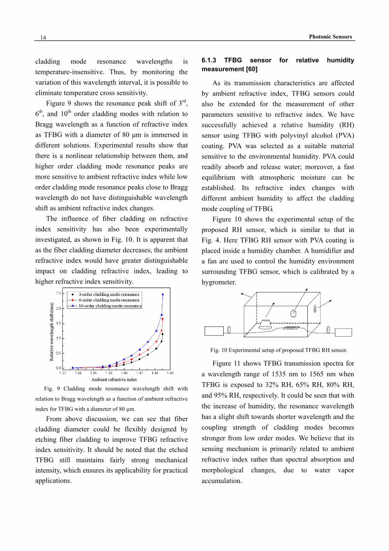
Figure 9 shows the resonance peak shift of 3rd, 6th, and 10th order cladding modes with relation to Bragg wavelength as a function of refractive index as TFBG with a diameter of 80 μm is immersed in different solutions. Experimental results show that there is a nonlinear relationship between them, and higher order cladding mode resonance peaks are more sensitive to ambient refractive index while low order cladding mode resonance peaks close to Bragg wavelength do not have distinguishable wavelength shift as ambient refractive index changes.
The influence of fiber cladding on refractive index sensitivity has also been experimentally investigated, as shown in Fig. 10. It is apparent that as the fiber cladding diameter decreases, the ambient refractive index would have greater distinguishable impact on cladding refractive index, leading to higher refractive index sensitivity.
Fig. 9 Cladding mode resonance wavelength shift with
relation to Bragg wavelength as a function of ambient refractive
index for TFBG with a diameter of 80 μm.
From above discussion, we can see that fiber cladding diameter could be flexibly designed by etching fiber cladding to improve TFBG refractive index sensitivity. It should be noted that the etched TFBG still maintains fairly strong mechanical intensity, which ensures its applicability for practical applications.
6.1.3 TFBG sensor for relative humidity measurement [60]
As its transmission characteristics are affected by ambient refractive index, TFBG sensors could also be extended for the measurement of other parameters sensitive to refractive index. We have successfully achieved a relative humidity (RH) sensor using TFBG with polyvinyl alcohol (PVA) coating. PVA was selected as a suitable material sensitive to the environmental humidity. PVA could readily absorb and release water; moreover, a fast equilibrium with atmospheric moisture can be established. Its refractive index changes with different ambient humidity to affect the cladding mode coupling of TFBG.
Figure 10 shows the experimental setup of the proposed RH sensor, which is similar to that in Fig. 4. Here TFBG RH sensor with PVA coating is placed inside a humidity chamber. A humidifier and a fan are used to control the humidity environment surrounding TFBG sensor, which is calibrated by a hygrometer.
Fig. 10 Experimental setup of proposed TFBG RH sensor.
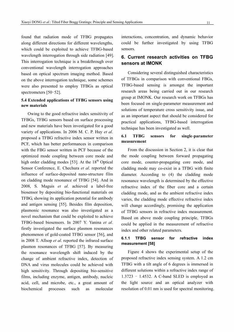
Figure 11 shows TFBG transmission spectra for a wavelength range of 1535 nm to 1565 nm when TFBG is exposed to 32% RH, 65% RH, 80% RH, and 95% RH, respectively. It could be seen that with the increase of humidity, the resonance wavelength has a slight shift towards shorter wavelength and the coupling strength of cladding modes becomes stronger from low order modes. We believe that its sensing mechanism is primarily related to ambient refractive index rather than spectral absorption and morphological changes, due to water vapor accumulation.
Xiaoyi DONG et al.: Tilted Fiber Bragg Gratings: Principle and Sensing Applications
15
1540 1545 1550 1555 1560-60
-55
-50
-45
-40
Wavelength (nm)
Tran
smiss
ion
loss
(dB)
-60
-55
-50
-45
-40
32%RH
65%RH
95%RH
-70-65-60-55-50-45-40-35-30
80%RH
-70-65-60-55-50-45-40-35-30
Fig. 11 Evolution of TFBG transmission spectrum under
different relative humidity.
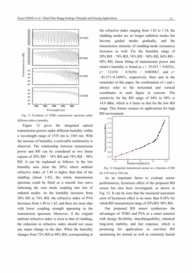
Figure 12 gives the integrated optical transmission powers under different humidity within a wavelength range of 1535 nm to 1565 nm. With the increase of humidity, a noticeable nonlinearity is observed. The relationship between transmission power and RH can be considered as two linear regions of 20% RH - 74% RH and 74% RH - 98% RH. It can be explained as follows: in the low humidity area (near the 20%) where ambient refractive index of 1.49 is higher than that of the cladding (about 1.45), the whole transmission spectrum could be fitted as a smooth loss curve indicating the core mode coupling into lots of radiated modes. As the humidity increases from 20% RH to 74% RH, the refractive index of PVA decreases from 1.49 to 1.42, and there are more dips with lower coupling strength appearing in the transmission spectrum. Moreover, if the original ambient refractive index is close to that of cladding, the reduction in refractive index should not cause any major change in the dips. When the humidity changes from 72% RH to 98% RH, corresponding to
the refractive index ranging from 1.42 to 1.34, the cladding modes are no longer radiation modes but become guided modes gradually, and the transmission intensity of cladding-mode resonances increases as well. For the humidity range of 20% RH - 74% RH, 74% RH - 98% RH, 84% RH - 98% RH, linear fitting of transmission power and relative humidity is found as y = 35.015 + 0.0252x, y= -12.674 - 0.5639x + 0.00388x2, and y= -45.371+0.14947x, respectively. Here and in the remainder of this paper, the combination of x and y always refer to the horizontal and vertical coordinates in each figure in concern. The sensitivity for the RH range of 84% to 98% is 14.9 dBm, which is 6 times as that for the low RH range. This feature ensures its applications for high RH environment.
Fig. 12 Integrated transmission power as a function of RH
for 1535 nm to 1565 nm.
As an important factor to evaluate sensor performances, hysteresis effect of the proposed RH sensor has also been investigated, as shown in Fig. 13. It can be seen that the measured maximum error of hysteresis effect is no more than 0.56% for whole RH measurement range of 20% RH-98% RH.
Our proposed RH sensor synthesizes the advantages of TFBG and PVA as a smart material with design flexibility, interchangeability, chemical long-term stability, and fast response, which is promising for applications in real-time RH monitoring for normal as well as extremely humid

Photonic Sensors
16
environment.
Fig. 13 Hysteresis curve of PVA-coated TFBG RH sensor
for a humidity range of 20% RH - 98% RH.
6.1.4 Bending and directional characteristics of TFBG [61]
For many structural monitoring and engineering measurement applications, it is very important to evaluate the structural bending with orientation information. Some studies have shown that a few special modes of TFBG are sensitive to bending [62]. As bending takes place, fiber turns into bending waveguide, and the cross section of TFBG would experience further bending or compression. And when the angle between bending direction and grating plane varies, the effective tilt angle will change accordingly. Therefore it is necessary to investigate the influence of bending direction on the mode coupling of TFBG.
As fiber bending takes place, the refractive index distribution over fiber cross section will change due to the photoelastic effect [63]:
2 2 2eff 0 eff2 2 2 2
0 0
1 2 1( ) ( ) ( )4 4
N x n x n xk R R k R
= + + − (7)
where 0 2 /k π λ= , R is bending radius, 0 ( )n x represents the initial refractive index distribution over fiber cross section, neff is the effective refractive index of mode in concern, and x refers to the radial coordinate in fiber cross section.
Opposite refractive index variation on both sides of fiber axis leads to the decrease of mode field overlap between core mode and cladding modes. Moreover, the change of effective index induced by fiber bending is related to the normalized frequency and mode order other than fiber curvature [64].
Figure 14 illustrates the experimental setup of bending and directional sensitivity test system. A 1.5 cm TFBG with 4-degree tilt angle is inserted into a capillary (its inner and outer diameters are 320 μm and 500 μm, respectively), both ends of which are fixed onto two moving stages. The fiber curvature could be controlled by moving the stages, and the fiber curvature could be described as
2 2
2dCd L
=+
(8)
where d is the vertical deviation of grating center and L refers to half of the distance between two stages. Two scaled round plate are employed to adjust bending direction.
Moving
OSA
Rotation
BBS
2L Fig. 14 Experimental setup of bending and directional
sensitivity test system.
Figure 15 shows TFBG evolution of transmission spectrum as fiber curvature increases for 0-degree angle between bending direction and grating plane. It can be seen that for a curvature range of 0 - 25 m−1, the resonance peaks of LP0n
cladding modes almost do not make any change, and no new cladding mode turns up. However, those of LP1n cladding modes obviously chirp, and the coupling strength decreases due to the reduction of mode field overlap between core mode and cladding modes.
Curvatureincrease
Tran
smis
sion
loss
(dB
)
1545 1550 1555 Wavelength(nm)
LP0n
LP1n
Fig. 15 Evolution of TFBG transmission spectrum as fiber
curvature increases for 0-degree angle between bending
direction and grating plane.

Xiaoyi DONG et al.: Tilted Fiber Bragg Gratings: Principle and Sensing Applications
17
To investigate the chirping characteristics induced by mode coupling between core mode and cladding modes in bending fiber, a 3-layer medium (fiber core, fiber cladding, and environment) waveguide model is utilized. The refractive index distribution over fiber cross section is illustrated in Fig. 16. As bending takes place, a gradient strain distribution along bending radius is established. The axial strain located in the neutral plane around fiber core is zero with cladding region above the neutral plane stretched and cladding region below the neutral plane compressed. Strain (ε) of different layers is determined by the distance x between bending radius R and the neutral plane:
xR
ε = . (9)
Fig. 16 Illustration of gradient strain distribution over fiber
cross section when fiber bending takes place.
Due to photoelastic effect, this strain will cause the refractive index change corresponding to x- and y-polarization modes [65]:
( )32
12 11( ) 1stn n p p Rν νΔ = − ⎡ − − ⎤⎣ ⎦ (10)
where ν is Poisson ratio, ijp represents the photoelastic coefficient, and n is effective refractive index. Considering the non-uniform strain distribution over cladding area, the resonance peaks of LP1n modes will chirp and the coupling strength will decrease accordingly. Assuming that efractive index modulation over fiber core is uniform, the resonance peak will experience uniform broadening, and the chirp bandwidth could be described by
( )1 eDpR
λΔ = − (11)
where 0.22ep = is effective photoelastic coefficient and D refers to fiber diameter. However, due to the change of tilt angle induced by fiber bending, the
transmission spectrum turns out more complex characteristics.
Figure 17 shows TFBG evolution of transmission spectrum as fiber curvature increases for 90-degree angle between bending direction and grating plane. From this figure, it could be seen that all of the cladding mode resonance peaks do not chirp or split. The coupling strength of LP0n modes considerably decreases while that of LP1n modes increases greatly. As a result, the coupling strength of LP1n modes is much higher than that of LP0n modes. According to coupled mode theory, the coupling strength of TFBG resonance peaks is determined by coupling coefficient of core mode and cladding modes, which could be described as
12cl co
0 1
2( ) cl co* cl co*
1 01 20 0
( ) ( )a
w n zr rz d rdr E E E E
πε σ
ν φ φκ φ−
− = +∫ ∫
(12) where co ( , )E r φ and cl ( , )E r φ represent the transverse electric fields of core mode and cladding modes, respectively.
Curvatureincrease
Tran
smis
sion
loss
(dB
)
1545 1550 1555 Wavelength(nm)
LP0n LP1n
Fig. 17 Evolution of TFBG transmission spectrum as fiber
curvature increases for 90-degree angle between bending
direction and grating plane.
The coupling coefficient is determined by refractive index modulation and the overlap integral of two coupled modes located in the refractive index modulated region. As UV-induced refractive index modulation is normally assumed to be uniform over fiber cross section, the coupling coefficient is primarily determined by the overlap between core
Photonic Sensors
18
mode and cladding modes. When fiber bending takes place, much of the core mode power will be coupled to fiber cladding, leading to the increase of overlap integral between core mode and LP1n
cladding modes, and due to energy conservation, the LP0n resonance peaks turn out an opposite trend.
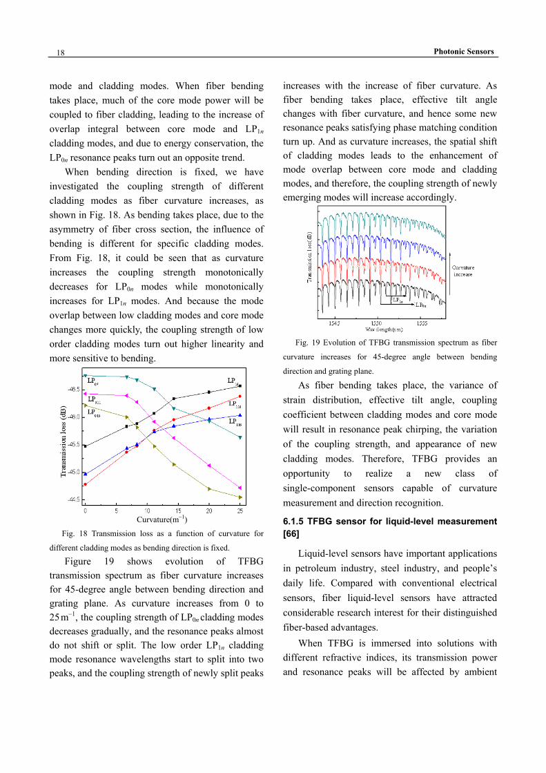
When bending direction is fixed, we have investigated the coupling strength of different cladding modes as fiber curvature increases, as shown in Fig. 18. As bending takes place, due to the asymmetry of fiber cross section, the influence of bending is different for specific cladding modes. From Fig. 18, it could be seen that as curvature increases the coupling strength monotonically decreases for LP0n modes while monotonically increases for LP1n modes. And because the mode overlap between low cladding modes and core mode changes more quickly, the coupling strength of low order cladding modes turn out higher linearity and more sensitive to bending.
Curvature(m−1) Fig. 18 Transmission loss as a function of curvature for
different cladding modes as bending direction is fixed.
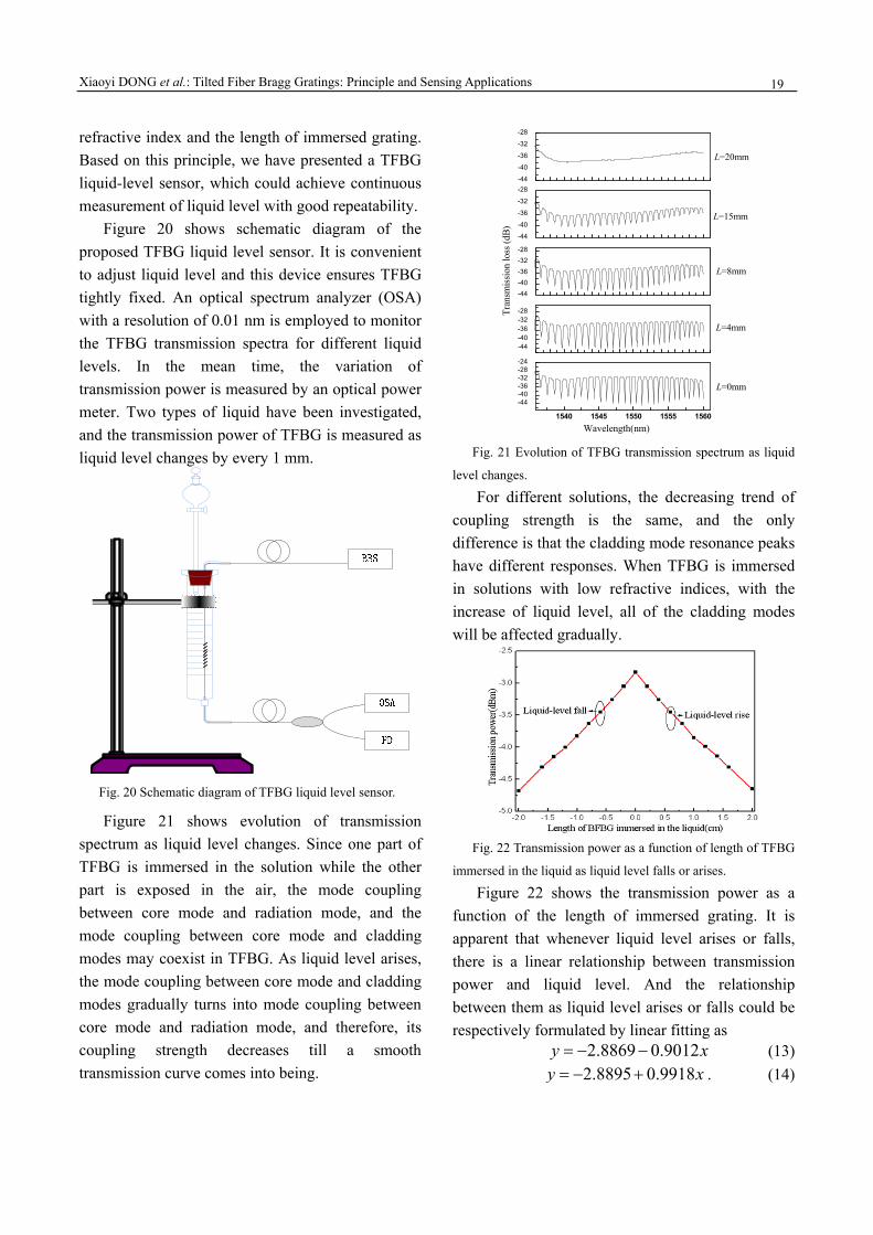
Figure 19 shows evolution of TFBG transmission spectrum as fiber curvature increases for 45-degree angle between bending direction and grating plane. As curvature increases from 0 to 25 m−1, the coupling strength of LP0n cladding modes decreases gradually, and the resonance peaks almost do not shift or split. The low order LP1n cladding mode resonance wavelengths start to split into two peaks, and the coupling strength of newly split peaks
increases with the increase of fiber curvature. As fiber bending takes place, effective tilt angle changes with fiber curvature, and hence some new resonance peaks satisfying phase matching condition turn up. And as curvature increases, the spatial shift of cladding modes leads to the enhancement of mode overlap between core mode and cladding modes, and therefore, the coupling strength of newly emerging modes will increase accordingly.
Fig. 19 Evolution of TFBG transmission spectrum as fiber
curvature increases for 45-degree angle between bending
direction and grating plane.
As fiber bending takes place, the variance of strain distribution, effective tilt angle, coupling coefficient between cladding modes and core mode will result in resonance peak chirping, the variation of the coupling strength, and appearance of new cladding modes. Therefore, TFBG provides an opportunity to realize a new class of single-component sensors capable of curvature measurement and direction recognition.
6.1.5 TFBG sensor for liquid-level measurement [66]
Liquid-level sensors have important applications in petroleum industry, steel industry, and people’s daily life. Compared with conventional electrical sensors, fiber liquid-level sensors have attracted considerable research interest for their distinguished fiber-based advantages.
When TFBG is immersed into solutions with different refractive indices, its transmission power and resonance peaks will be affected by ambient
Xiaoyi DONG et al.: Tilted Fiber Bragg Gratings: Principle and Sensing Applications
19
refractive index and the length of immersed grating. Based on this principle, we have presented a TFBG liquid-level sensor, which could achieve continuous measurement of liquid level with good repeatability.
Figure 20 shows schematic diagram of the proposed TFBG liquid level sensor. It is convenient to adjust liquid level and this device ensures TFBG tightly fixed. An optical spectrum analyzer (OSA) with a resolution of 0.01 nm is employed to monitor the TFBG transmission spectra for different liquid levels. In the mean time, the variation of transmission power is measured by an optical power meter. Two types of liquid have been investigated, and the transmission power of TFBG is measured as liquid level changes by every 1 mm.
Fig. 20 Schematic diagram of TFBG liquid level sensor.
Figure 21 shows evolution of transmission spectrum as liquid level changes. Since one part of TFBG is immersed in the solution while the other part is exposed in the air, the mode coupling between core mode and radiation mode, and the mode coupling between core mode and cladding modes may coexist in TFBG. As liquid level arises, the mode coupling between core mode and cladding modes gradually turns into mode coupling between core mode and radiation mode, and therefore, its coupling strength decreases till a smooth transmission curve comes into being.
1540 1545 1550 1555 1560
-44-40-36-32-28-24
L=20mm
L=15mm
L=4mm
Wavelength(nm)
L=0mm
L=8mm
-44-40-36-32-28
-44-40-36-32-28
-44
-40
-36
-32
-28
Tran
smiss
ion
loss
(dB)
-44
-40
-36
-32
-28
L=20mm
L=15mm
L=8mm
L=4mm
L=0mm
Fig. 21 Evolution of TFBG transmission spectrum as liquid
level changes.
For different solutions, the decreasing trend of coupling strength is the same, and the only difference is that the cladding mode resonance peaks have different responses. When TFBG is immersed in solutions with low refractive indices, with the increase of liquid level, all of the cladding modes will be affected gradually.
Fig. 22 Transmission power as a function of length of TFBG
immersed in the liquid as liquid level falls or arises.
Figure 22 shows the transmission power as a function of the length of immersed grating. It is apparent that whenever liquid level arises or falls, there is a linear relationship between transmission power and liquid level. And the relationship between them as liquid level arises or falls could be respectively formulated by linear fitting as
2.8869 0.9012y x= − − (13) 2.8895 0.9918y x= − + . (14)

Photonic Sensors
20
The corresponding coefficients of determination reach 0.9982 and 0.9989, respectively.
Owing to power interrogation through photoelectric detector, the proposed liquid level sensor has several advantages such as simple interrogation method, low cost, and ease of construction.
6.2 Temperature cross sensitivity of TFBG sensors
In many occasions, temperature is an important factor that has impact on sensor performances, but unfortunately, like common FBGs, the transmission characteristics of TFBGs are temperature sensitive, and hence how to eliminate temperature cross senility is an issue that has to be considered for practical applications of TFBG sensors.
6.2.1 TFBG sensor for simultaneous measurement of strain and temperature [67]
The transmission characteristics of TFBG are sensitive to both temperature and strain, and experimental results indicate that like common the FBG, core mode and cladding modes of TFBG possess the same temperature sensitivity but different strain sensitivity. By exploiting these characteristics, we have proposed and experimentally demonstrated a TFBG sensor for simultaneous measurement of temperature and strain.
The resonance wavelength shift of core mode and cladding modes induced by the variation of temperature and strain could be expressed as
eff eff
eff eff
Bragg, Bragg,
1 1 1 1g gB
B g g
T
n nTn T T n
K T K ε
Λ Λλ ελ Λ Λ ε ε
ε
⎛ ⎞ ⎛ ⎞∂ ∂∂ ∂Δ= + Δ + + Δ⎜ ⎟ ⎜ ⎟⎜ ⎟ ⎜ ⎟∂ ∂ ∂ ∂⎝ ⎠ ⎝ ⎠= Δ + Δ
(15)
eff ,core eff ,cladclad
clad eff ,core eff ,clad
eff ,core eff ,clad
eff ,core eff ,clad
clad, clad,
( )1 1
( )1 1
i iig
i i ig
i ig
i ig
T
n nT
n n T T
n nn n
K T K ε
Λλλ Λ
Λε
Λ ε ε
ε
⎧ ⎫∂∂ +Δ ⎪ ⎪= + Δ⎨ ⎬+ ∂ ∂⎪ ⎪⎩ ⎭⎧ ⎫∂ ∂ +⎪ ⎪+ + Δ⎨ ⎬∂ + ∂⎪ ⎪⎩ ⎭
= Δ + Δ
(16)
where KBragg,T and Kclad,T represent thermal expansion coefficient and thermo-optic constant of fiber
respectively, KBragg,ε and Kclad,ε refer to the constants related to fiber Poisson ratio, photoelastic coefficient, and the effective refractive indices of fiber core and fiber cladding respectively.
Thus the variation of temperature and strain could be simultaneously determined by solving the sensing matrix:
Bragg, Bragg,Bragg
clad, clad,clad
T
T
K K TK K
ε
ε
λελ
Δ ⎛ ⎞⎛ ⎞ Δ⎛ ⎞= ⎜ ⎟⎜ ⎟ ⎜ ⎟⎜ ⎟ ΔΔ ⎝ ⎠⎝ ⎠ ⎝ ⎠
(17)
where ΔλBragg and Δλclad represent the resonance wavelength shift of core mode and cladding modes respectively, εΔ and TΔ refer to the variation of strain and temperature respectively. Therefore, by experimentally measuring KBragg,T, Kclad,T, KBragg,ε, and Kclad,ε, the variation of temperature and strain could be calculated through the following matrix:
1Bragg, Bragg, Bragg
clad, clad, clad
T
T
K KTK K
ε
ε
λε λ
−Δ⎛ ⎞ ⎛ ⎞Δ⎛ ⎞
= ⎜ ⎟ ⎜ ⎟⎜ ⎟ ⎜ ⎟Δ Δ⎝ ⎠ ⎝ ⎠⎝ ⎠. (18)
In our experiment, the thermal characteristics of core mode and cladding modes were studied by placing TFBG in a temperature-controlled chamber with resolution of 0.18 ℃. And the strain characteristics of TFBG have been also studied by attaching TFBG close to the fixed end of a cantilever beam. Transmission spectra of TFBG were monitored by using an optical spectrum analyzer with resolution of 0.01 nm.
The temperature-induced resonance wavelength shifts of core mode and a certain cladding mode are shown in Fig. 23. As temperature increases, the resonance peaks of core mode and cladding mode linearly shift toward longer wavelength with the same temperature sensitivity of 0.011 nm/℃, and their corresponding coefficients of determination reach 0.9994 and 0.9995, respectively.
We have also experimentally investigated the strain-induced resonance wavelength shifts of core mode and cladding mode, as shown in Fig. 24. It could be seen that as strain increases, both of the resonance wavelengths of core mode and cladding

Xiaoyi DONG et al.: Tilted Fiber Bragg Gratings: Principle and Sensing Applications
21
mode linearly increase as well, but they have different strain sensitivity. Their corresponding coefficients of determination reach 0.9966 and 0.998, respectively.
λ ,nm
λ ,nm
Temperature,℃
Fig. 23 Temperature responses of core mode and cladding
mode resonance wavelengths.
From above experimental results, four coefficients KBragg,T, KBragg,ε, Kclad,T, and Kclad,ε are found to be 11.1 pm/℃, 0.657 pm/με, 11.1 pm/℃, and 0.766 pm/με, respectively. And thus variation of temperature and strain could be calculated simultaneously according to (18).
λ ,nm
λ ,nm
Strain, u Fig. 24 Strain responses of core mode and cladding mode
resonance wavelengths.
6.2.2 TFBG sensor for simultaneous discrimination of bending and temperature [68]
For structure monitoring applications, it is important to solve temperature cross sensitivity issue with simple system structure and low cost interrogation approach. Based on different bending and temperature characteristics of core mode and cladding modes of TFBG, we have presented a TFBG sensor for simultaneous discrimination of bending and temperature, which has good potential in practical structure monitoring applications.
To investigate the bending characteristics of TFBG, in our experiment a 1.3 cm TFBG with 2-degree tilt angle is placed along a series of V-grooved half circles with different radii, as shown in Fig. 25. An OSA with resolution of 0.01 nm and a power meter are utilized to monitor the transmission spectrum and transmission power, respectively. And to study its temperature characteristics, TFBG is placed in a temperature-controlled chamber.
BBS OSA Fig. 25 Experimental setup of bending/temperature
characteristics test system.
Figure 26 shows evolution of TFBG transmission spectrum for constant temperature environment as fiber curvature increases. It is apparent that due to the change of effective tilt angle, the cladding mode and core mode resonance peaks turn out different trends as fiber curvature increases. For cladding modes, the transmission power gradually decreases from lower orders. As the bending radius increases from 2.5 cm to 13.55 cm, the transmission loss of low order cladding modes almost linearly decreases, while the high order cladding modes are not influenced.
ρ=40
ρ=30.77
ρ=23.53
ρ=17.7
ρ=14.39
ρ=11.90
ρ=8.70
ρ=7.38
ρ=0 ρ:m−1
Fig. 26 Evolution of TFBG transmission spectrum for
constant temperature environment as fiber curvature increases.
From Fig. 26, we could also find that as fiber curvature increases from 0 to 40 m−1, the transmission loss of core mode does not make any

Photonic Sensors
22
distinguishable change, while the ghost mode and the cladding modes close to it are affected to some degree. But the variation of fiber curvature does not have an influence on the resonance wavelengths of cladding mode, ghost mode, and core mode.
Temperature and curvature characteristics of TFBG sensor for a temperature range of 15 ℃ - 60 ℃ with a fixed fiber curvature of 23.53 m−1 are shown in Figs. 27 and 28, respectively. As temperature increases the cladding mode resonance wavelength would shift toward longer wavelength, and because thermal expansion coefficient of silica-based fiber and temperature coefficients of core mode and cladding modes are normally negligible, all of the cladding mode resonance peaks approximately possess the same temperature sensitivity.
T=60T=55
T=50
T=45T=40
T=35T=25
T=15
T:℃
Fig. 27 Evolution of TFBG transmission spectrum for fixed
fiber curvature as temperature increases.
Fig. 28 Transmission power of cladding modes as a function
of temperature.
From above discussion, it could be summarized that as fiber curvature is fixed, the resonance
wavelengths of cladding modes and core mode increase with the increase of temperature, however, their transmission loss is temperature-independent.
Figure 29 shows transmission power of cladding mode as a function of fiber curvature. It could be seen that transmission power linearly decreases as fiber curvature increases, and the relationship between them could be formulated through linear fitting as
2.6249 0.0027y x= − . (19) The temperature responses of core mode and
cladding mode resonance peaks are shown in Fig. 30. There also exists linear relationship between the resonance peak shift and temperature, which could be respectively expressed as
1566.16 0.01076coy x= + (20) 1556.98 0.01085cly x= + . (21)
Fig. 29 Transmission power of cladding mode as a function
of fiber curvature.
Fig. 30 Resonance wavelength shift of core mode and low
order cladding mode as functions of temperature.
From above experimental results, it could be seen that the resonance peaks of core mode and high order cladding modes are insensitive to fiber

Xiaoyi DONG et al.: Tilted Fiber Bragg Gratings: Principle and Sensing Applications
23
bending, but the transmission power of cladding modes are bending-dependent. Moreover, the resonance wavelengths of core mode and cladding mode are sensitive to temperature, but their transmission power is temperature-independent. Based on these unique characteristics of TFBG, we could achieve simultaneous discrimination of bending and temperature. Our proposed sensor has several advantages such as low cost, compact size, ease of construction, and availability of being embedded into smart materials.
6.3 TFBG-based interrogation technique
The interrogation technique of fiber grating sensors has been a subject of extensive studies for a long time. Typical interrogation approaches include inference method and filtering method, the applications of which are seriously limited by many factors such as system cost, multiplexing capability, measurement range, and system resolution. Based on the flexibility of TFBG spectrum envelope and temperature characteristics of TFBG similar to common FBGs, we have investigated the TFBG-based all-fiber interrogation technique with low cost, design flexibility, and applicability for practical applications.
6.3.1 TFBG-based edge filtering interrogation technique [69]
From the discussion in Section 6.1, we could see that as TFBG is exposed in the air, its transmission spectrum consists of a series of discrete resonance peaks resulting from the mode coupling between core mode and cladding modes. And when TFBG is immersed in solutions with refractive index close to its cladding refractive index, cladding mode will be coupled into radiation mode and a smooth transmission spectrum forms accordingly, which may be utilized for edge filtering interrogation.
Figure 31 shows the transmission spectrum of TFBG immersed in index matching gel. It is clear that there are two linear edge regions around 1505 nm - 1540 nm and 1540 nm - 1565 nm,
respectively. As the transmission loss changes monotonically within above wavelength range, it is possible to realize linear edge filtering interrogation using a single TFBG. We have investigated the edge filtering characteristics of the rise edge. A tunable laser operating from 1530 nm to 1610 nm is employed as light source.
Fig. 31 Transmission spectrum of TFBG immersed in index
matching gel.
Figure 32 shows the experimental setup of TFBG-based edge filtering interrogation system. TFBG is immersed in index matching gel (IMG) to obtain a smooth transmission spectrum profile. And in order to eliminate the influence of source power fluctuation on system performances, a 3dB coupler is employed to separate input light into two portions. The output light is guided to an OSA and a photoelectric detector for spectral and power monitoring via an optical switch.
Tunable Laser
TFBG Index
Matching Gel
OpticalSwitch OSA
Reference Branch Branch 1
Branch 2
3dB
Fig. 32 Experimental setup of TFBG-based edge filtering
interrogation system.
For our proposed interrogation system, the normalized transmission function ( )H λ could be described as
2 1( ) ( ) / ( )H I Iλ λ λ= (22) where 2 ( )I λ and 1( )I λ refer to the transmission power of TFGB and the optical power of reference

Photonic Sensors
24
branch, respectively. Figure 33 shows the transmission power of
TFBG for different laser wavelengths. It could be seen that the laser intensity for different wavelengths has similar profile to rise edge of TFBG transmission spectrum.
By measuring the light power of two branches in Fig. 32, we have experimentally studied the normalized transmissivity as a function of wavelength, as shown in Fig. 34. And through linear fitting, ( )H λ could be described as
2 1( ) = ( ) / ( ) 0.014 22.078 H I Iλ λ λ λ= − . (23)
Fig. 33 Transmission power of TFBG for different laser
wavelengths.
H(λ
)
Fig. 34 Normalized transmissivity as a function of
wavelength.
Above expression indicates that by measuring the power ratio of TFBG branch and reference branch in Fig. 32, the laser wavelength can be calculated. Thus wavelength interrogation could be achieved by using TFBG immersed in solutions with refractive index close to that of fiber cladding. It should be also noted that the transmission profile of TFBG could be flexibly controlled by adjusting tilt
angle and exposure time, which ensures the flexibility of TFBG-based interrogation method for practical applications.
6.3.2 TFBG-based dynamic temperature compensation interrogation technique for strain sensors [70]
For engineering applications, strain is an important parameter related to the structure health information. However, conventional FBG strain sensors are seriously affected by temperature cross sensitivity, which degrades the sensing system performances and sometimes leads to error judgment of the interrogation system. In previous section, we have experimentally demonstrated a TFBG-based edge filtering interrogation system. Since the transmission spectrum envelope of cladding modes has the same temperature sensitivity with Bragg wavelength of FBG, the temperature effect on Bragg wavelength of FBG strain sensors could be possibly compensated.
Figure 35 shows our proposed TFBG-based dynamic temperature interrogation system for strain sensors. A TFBG with 8-degree tilt angle is utilized as temperature compensation component. Its rise edge and fall edge are located within 1550 nm - 1562 nm and 1530 nm - 1550 nm, respectively. An FBG with Bragg wavelength of 1539.3 nm is pasted onto a uniform cantilever beam to work as strain sensor. A 3dB coupler is employed to separate the light reflected by FBG sensor into signal branch and reference branch to eliminate the influence of source power fluctuation on system performances. Two photoelectric detectors are utilized to measure the TFBG transmission power and the light power of reference branch.
Fig. 35 Schematic diagram of TFBG-based dynamic
temperature interrogation system for strain sensors.

Xiaoyi DONG et al.: Tilted Fiber Bragg Gratings: Principle and Sensing Applications
25
Figure 36 shows temperature responses of TFBG core mode and cladding mode resonance peaks. It is apparent that both of the core mode and cladding mode resonance wavelengths linearly shift toward longer wavelength as temperature increases, and their corresponding coefficients of determination reach 0.999 and 0.998, respectively. Experimental results show that the core mode and cladding mode have similar temperature sensitivity of about 10.7 pm/℃, which is very close to temperature sensitivity of common FBGs. This feature could be exploited for dynamic temperature compensation of strain interrogation system.
Fig. 36 Temperature responses of core mode and cladding
mode resonance wavelengths.
We have measured the power ratio of D2 and D1 in Fig. 36 at 25℃ for different strains, as shown in Fig. 37. There is a linear relationship between them and the coefficient of determination reaches 0.9993. The linear wavelength interrogation range is 6 nm with a strain sensing resolution of 2.5532×10⁻⁶/με. From Fig. 37, it could also be seen that the power ratio of D2 and D1 has almost the same strain sensitivity at different temperatures, and the slope as a function of temperature is shown in Fig. 38. Therefore, the proposed interrogation system could be utilized for the elimination of temperature effect on strain sensor performances.
From above analysis, we can see that as temperature changes, TFBG could be employed as a temperature compensation component to realize dynamic interrogation of FBG strain sensors.
Compared with other interrogation components, TFBG has several advantages such as simple structure, low cost, and high reliability, which paves a new way for interrogation of distributed FBG sensor networks.
Fig. 37 Ratio of optical intensity as functions of strain at
different temperatures.
Slop
e of
I/μ
Fig. 38 Relationship between temperature and slope.
7. Brief summary on the key techniques of TFBG sensors
The uprising of TFBG-based sensing technology paves a new way for the development of multi-dimensional photonic devices. Fiber gratings with quasi two-dimensional structures have greatly expanded the functionality of one-dimensional fiber components. By controlling tilted angle and refractive index modulation, TFBGs with multi-dimensional pitches could be achieved, allowing for more versatile interaction between photons. Therefore, TFBGs have provided a brand new approach for experimental and theoretical investigations of multi-dimensional photonic devices.

Photonic Sensors
26
As an important member of the big photonic sensor family, much effort has been put on developing novel TFBG-based sensors, the key techniques of which generally involves:
1)Single-/multiple-parameter measurement technique
Besides the measurement of single physical parameter, owing to the existence of cladding mode resonance peaks, multiple-parameter measurement could be achieved with a single TFBG as well.
2)High resolution sensing technique Since the coupling modes of TFBGs have
narrower bandwidth and better temperature stability, compared with LPGs, TFBG sensors would be more suitable for high resolution sensing applications.
3)TFBGs based on new materials By depositing sensitive materials, e.g. polymer
film and metal medium with controllable thickness, through appropriate approaches, novel TFBG sensors could be developed for applications in many interdisciplinary areas.
4)TFBG-based interrogation technique Due to the special structure of TFBGs, light with
different wavelengths will be spatially dispersed through side radiation, which could be employed for all-fiber interrogation incomparable with conventional electrical-assisted interrogation approaches.
5)TFBG-based polarization control technique The polarization-dependent characteristics of
TFBG make it a good candidate for applications in polarization controlling and high power polarized lasers.
In a word, the optical characteristics of TFBGs are determined by many factors, including tilted angle, refractive index modulation, exposure time, grating pitch, and geometry of the grating structure, etc. Therefore, their spectral characteristics could be flexibly tailored through fabrication technique modification and grating structure design, which ensures the versatility and expandability of TFBG sensors.
8. Prospects of research and applications of TFBGs
As a newly emerging photonic component with distinguished features, TFBG deserves further investigations on its characteristics and applications. In our opinion, with the development of fiber fabrication technique, the research and applications of TFBGs are expected to make breakthrough in the following aspects:
1)Fabrication technique and grating structure a)Optimization and further explorations of
fabrication technique. b)Fabrication and study on TFBGs with special
structures such as large tilted, spiral, and non-uniform TFBGs.
c)Fabrication and study on superstructure fiber gratings with different tilt angles.
d)TFBGs written in large mode area fibers. 2)Research on TFBG sensors a)Construction of distributed sensor networks by
using appropriate TFBG-based interrogation approach.
b)Further investigations of mode coupling between core mode and cladding modes, e.g. when TFBG is immersed in solutions with refractive indices higher than cladding refractive index.
c)Biochemical sensing applications of TFBGs based on their good refractive index response, e. g. TFBG-based surface plasmonic resonance sensors.
3)Research on TFBGs in the field of optical communications
a)Investigation of dispersion, polarization characteristics of TFBGs.
b)Study on single-polarization and high power single-polarization fiber lasers.
4)Novel fiber gratings with new structures and materials
a)Fibers with different photosensitivity. b)Microstructured fibers. c)Polymer fibers.

Xiaoyi DONG et al.: Tilted Fiber Bragg Gratings: Principle and Sensing Applications
27
9. Conclusions
In summary, an overview on theoretical progress and research development of TFBG sensors from a worldwide perspective is presented followed by an introduction to current research work on TFBG sensors at IMONK. Due to their distinguished characteristics compared with common FBGs, TFBG sensors have attracted considerable research interest in the past few decades and will be an active research area for a long period. However, the current research and development of TFBG sensors are still far from meeting engineering demands, and there are still many issues awaiting further investigations. And as a novel photonic component with several unique features, TFBG could find it a subject of extensive studies from fiber sensing technology to biochemical applications.
Acknowledgment
This work was jointly supported by the National Key Natural Science Foundation of China under Grant No. 60736039, the National Natural Science Foundation of China under Grant No. 10904075, the National Natural Science Foundation of China under Grant No. 11004110, the Fundamental Research Funds for the Central Universities, the National Key Basic Research and Development Program of China under Grant No. 2010CB327605, and the National Natural Science Foundation of China under Grant No. 50802044.
References
[1] K. O. Hill, Y. Fujii, D. C. Johnson, and B. S. Kawasaki, “Photosensitivity in optical fiber waveguides: Application to reflection fiber fabrication,” Appl. Phys. Lett., vol. 32, no. 10, pp. 647-649, 1978.
[2] J. Jung, H. Nam, B. Lee, J. O. Byun, and N. S. Kim, “Fiber Bragg grating temperature sensor with controllable sensitivity,” Appl. Opt., vol. 38, no. 13, pp. 2752-2754, 1999.
[3] Z. C. Zhuo and B. S. Ham, “A temperature-insentive strain sensor using a fiber Bragg grating,” Opt. Fiber Technol., vol. 15, no. 5-6, pp. 442-444, 2009.
[4] P. K. C. Chan, W. Jin, K. T. Lau, L. M. Zhou, and M. S. Demokan, “Multi-point strain measurement of composite-bonded concrete materials with a RF-band FMCW multiplexed FBG sensor array,” Sens. Actuators A: Phys., vol. 87, no. 1-2, pp. 19-25, 2000.
[5] H. Ahmad, W. Y. Chong, K. Thambiratnam, M. Z. Zulklifi, P. Poopalan, M. M. M. Thant, and S. W. Harun, “High sensitivity fiber Bragg grating pressure sensor using thin metal diaphragm,” IEEE Sens. J., vol. 9. no. 12, pp. 1654-1659, 2009.
[6] X. Zeng and Y. Rao, “Simultaneous static strain, temperature and vibration measurement using an integrated FBG/EFPI sensor,” Chin. Phys. Lett., vol. 18, no. 12, pp. 1617-1619, 2001.
[7] G. Meltz, W. W. Morey, and W. H. Glenn, “In-fibre Bragg grating tap,” presented at Optical fiber Communication Conference, OFC’90, San Francisco, CA, 1990.
[8] M. C. P. Huy, G. Laffont, V. Dewynter, P. Ferdinand, L. Labonte, D. Pagnoux, P. Roy, W. Blanc, and B. Dussardier, “Tilted fiber Bragg grating photowritten in microstructured optical fiber for improved refractive index measurement,” Opt. Express, vol. 14, no. 22, pp. 10359-10370, 2006.
[9] L. Brilland, D. Pureur, J. F. Bayron, and E. Delevaque, “Slanted gratings UV-written in photosensitive cladding fibre,” Electron. Lett., vol. 35, no. 3, pp. 234-236, 1999.
[10] J. M. Battiato and R. K. Kostuk, “45°slanted fibre Bragg grating design with prism coupled holographic exposure,” Electron. Lett., vol. 38, no. 22, pp. 1323-1324, 2002.
[11] P. S. Westbrook, T. A. Strasser, and T. Erdogan, “In-line polarimeter using blazed fiber gratings,” IEEE Photon. Technol. Lett., vol. 12, no. 10, pp. 1352-1354, 2000.
[12] T. Ergodan and J. E. Sipe, “Tilted fiber phase gratings,” J. Opt. Soc. Am. A, vol. 13, no. 2, pp. 296-313, 1996.
[13] A. Bouzid and M. A. G. Abushagur, “Scattering analysis of slanted fiber gratings,” Appl. Opt., vol. 36, no. 3, pp. 558-562, 1997.
[14] T. Erdogan, “Cladding-mode resonances in short- and long period fiber grating filters,” J. Opt. Soc. Am. A, vol. 14, no. 8, pp. 1760-1773, 1997.
[15] K. S. Lee and T. Erdogan, “Transmissive tilted gratings for LP01-to-LP11 mode coupling,” IEEE Photon. Technol. Lett., vol. 11, no. 10, pp.1286-1288, 1999.
[16] T. Erdogan and J. E. Sipe, “Radiation-mode coupling loss in tilted fiber phase gratings,” Opt. Lett., vol. 20, no. 18, pp.1838-1840, 1995.

Photonic Sensors
28
[17] Y. Li, M. Froggatt and T. Erdogan, “Volume current method for analysis of tilted fiber gratings,” IEEE J. Lightwave Technol., vol. 19, no. 10, pp. 1580-1591, 2001.
[18] R. B. Walker, S. J. Mihailov, P. Lu, and D. Grobnic, “Shaping the radiation field of tilted fiber Bragg gratings,” J. Opt. Soc. Am. B, vol. 22, no. 5, pp. 962-975, 2005.
[19] C. Jáuregui and J. M. Lo’pez-Higuera, “Near-field theoretical model of radiation from a uniform-tilted fiber Bragg grating,” Microw. Opt. Technol Lett., vol. 37, no. 2, pp. 124-127, 2003.
[20] Y. Li and T. G. Brown, “Radiation modes and tilted fiber gratings,” J. Opt. Soc. Am. B, vol. 23, no. 8, pp. 1544-1555, 2006.
[21] R. Kashyap, R. Wyatt, and R. J. Campbell, “Wideband gain flattened erbium fiber amplifier using a photosensitive fiber blazed grating,” Electron. Lett., vol. 29, no. 2, pp. 154-156, 1993.
[22] R. Kashyap, R. Wyatt, and P. F. Mckee, “Wavelength flattened saturated erbium amplifier using multiple side-tip Bragg gratings,” Electron. Lett., vol. 29, no. 11, pp. 1025-1026, 1993.
[23] E. Kerrinckx, A. Hidayat, P. Niay, Y. Quiquempois, M. Douay, I. Riant, and C. D. Barros, “Suppression of discrete cladding mode resonances in fiber slanted Bragg gratings for gain equalisation,” Opt. Express, vol. 14, no. 4, pp. 1388-1394, 2006.
[24] C. W. Haggans, H. Singh, W. F. Varner, Y. Li, and M. Zippin, “Narrow-band rejection filters with negligible back reflection using tilted photoinduced gratings in single-mode fibers,” IEEE Photon. Technol. Lett., vol. 10, no. 5, pp. 690-692, 1998.
[25] Y. Liu, L. Zhang, and I. Bennion, “Fabricating fibre edge filters with arbitrary spectral response based on tilted chirped grating structures,” Meas. Sci. Technol., vol. 10, no. 1, pp. L1-L3, 1999.
[26] G. Nemova, J. Chauve, and R. Kashyap, “Design of sidetap fiber Bragg grating filters,” Opt. Commun., vol. 259, no. 2, pp. 649-654, 2006.
[27] R. S. Westbrook, K. S. Feder, P. I. Reyes, P. Steinvurzel, B. J. Eggleton, R. G. Ernst, L. A. Reith, and D. M. Gill, “Application of fibre Bragg grating filter/tap module to a wavelength-locked low-chirp directly-modulated 10 GB/s RZ transmitter,” presented at Optical Fiber Communication Conference, Anaheim, CA, March 17-22, 2002.
[28] H. S. Park, S. H. Yun, I. K. Hwang, S. B. Lee, and B. Y. Kim, “All-fibre add-drop wavelength-division multiplexer based on intermodal coupling,” IEEE Photon. Technol. Lett., vol. 13, no. 5, pp. 460-462,
2001. [29] K. W. Gaff, F. Ladouceur, and J. D. Love,
“Two-wavelength planar add/drop WDM filter employing a three-mode coupling Bragg grating,” Electron. Lett., vol. 36, no. 13, pp. 1142-1144, 2000.
[30] E. Marin, R. Ghosh, J. P. Meunier, X. Daxhelet, and S. Lacoix, “Bragg gratings in 2×2 symmetric fused fibre couplers: influence of the tilt on the wavelength response,” IEEE Photon. Technol. Lett., vol. 11, no. 11, pp. 1434-1436, 1999.
[31] K. Zhou, X. Chen, A. G. Simpson, L. Zhang, and I. Bennion, “High extinction ratio in-fiber polarizer based on 45°tilted fiber Bragg gratings,” Opt. Lett., vol. 30, no. 11, pp. 1285-1287, 2005.
[32] S. J. Mihailov, R. B. Walker, T. J. Stocki, and D. C. Johnson, “Fabrication of tilted fiber-grating polarisation-dependent loss equaliser,” Electron. Lett., vol. 37, no. 5, pp. 284-286, 2001.
[33] P. I. D. C. Reyes and P. S. Westbrook, “Tunable PDL of twisted-tilted fiber gratings,” IEEE Photon. Technol. Lett., vol. 15, no. 6, pp. 828-830, 2003.
[34] R. Suo, X. Chen, K. Zhou, L. Zhang, and I. Bennion, “In-fibre directional transverse loading sensor based on excessively tilted fibre Bragg gratings,” Meas. Sci. Technol., vol. 20, no. 3, pp. 034015, 2009.
[35] C. Caucheteur, S. Bette, C. Chen, M. Wuilpart, P. Megret, and J. Albert, “Tilted fiber Bragg grating refractometer using polarization-dependent loss measurement,” IEEE Photon. Technol. Lett., vol. 20, no. 24, pp. 2153-2155, 2008.
[36] C. Caucheteur, C. Chen, J. Albert, and P. Mégret, “Use of weakly tilted fiber Bragg gratings for sensing purpose,” presented at Optical Sensors 2008, Strasbourg, France, Apr. 7-10, 2008.
[37] C. Chen, C. Caucheteur, P. Mégret, and J. Albert, “The sensitivity characteristics of tilted fiber Bragg grating sensors with different cladding thickness,” Meas. Sci. Technol., vol. 18, no. 10, pp. 3117-3122, 2007.
[38] T. Guo, A. Ivanov, C. Chen, and J. Albert, “Temperature-independent tilted fiber grating vibration sensor based on cladding-core recoupling,” Opt. Lett., vol. 33, no. 9, pp. 1004-1006, 2008.
[39] C. Chen and J. Albert, “Strain-optic coefficients of individual cladding modes of single mode fiber: theory and experiment,” Electron. Lett., vol. 42, no. 18, pp. 1027-1028, 2006.
[40] S. Baek, Y. Jeong, and B. Lee, “Characteristics of short-period blazed fibre Bragg gratings for use as macro-bending sensors,” Appl. Opt., vol. 41, no. 4, pp. 631-636, 2002.
[41] C. Caucheteur, K. Chah, F. Lhommé, M. Blondel,
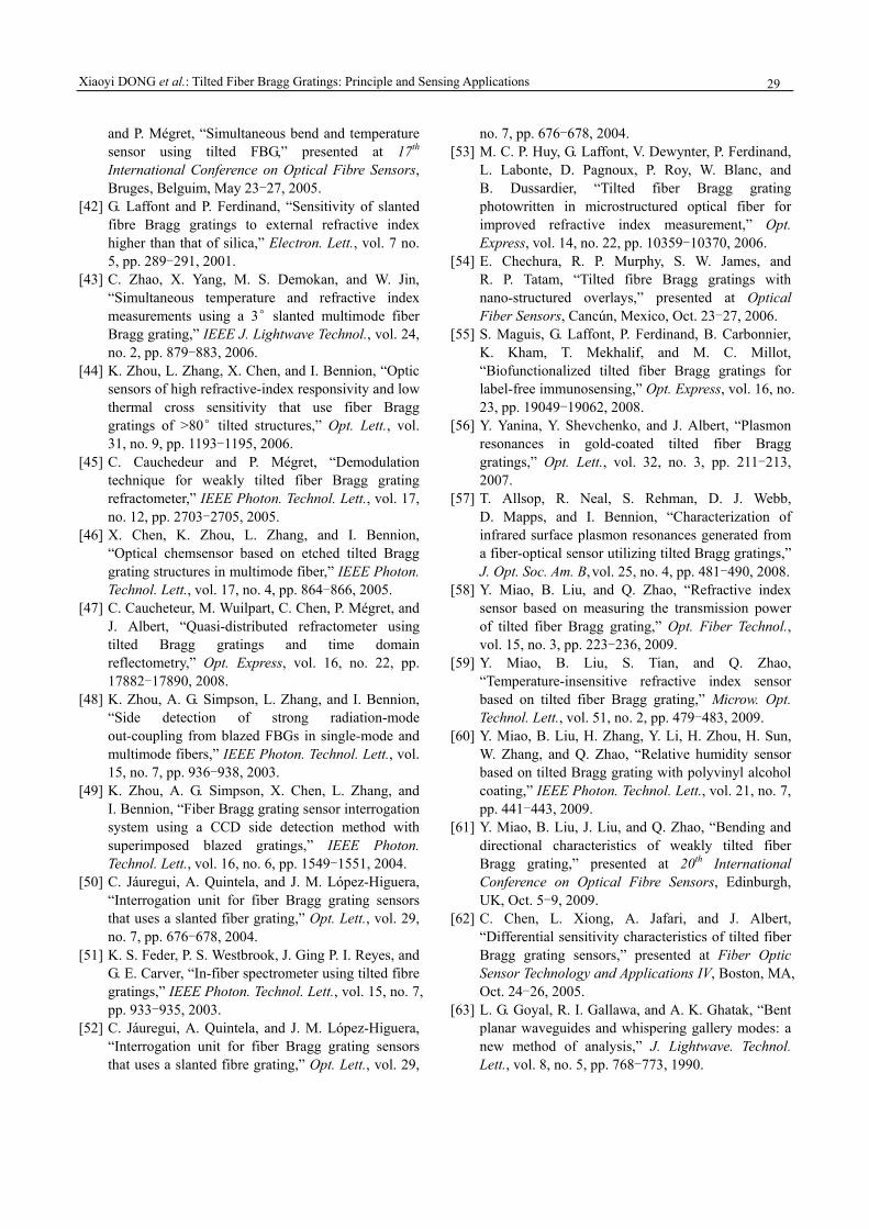
Xiaoyi DONG et al.: Tilted Fiber Bragg Gratings: Principle and Sensing Applications
29
and P. Mégret, “Simultaneous bend and temperature sensor using tilted FBG,” presented at 17th International Conference on Optical Fibre Sensors, Bruges, Belguim, May 23-27, 2005.
[42] G. Laffont and P. Ferdinand, “Sensitivity of slanted fibre Bragg gratings to external refractive index higher than that of silica,” Electron. Lett., vol. 7 no. 5, pp. 289-291, 2001.
[43] C. Zhao, X. Yang, M. S. Demokan, and W. Jin, “Simultaneous temperature and refractive index measurements using a 3°slanted multimode fiber Bragg grating,” IEEE J. Lightwave Technol., vol. 24, no. 2, pp. 879-883, 2006.
[44] K. Zhou, L. Zhang, X. Chen, and I. Bennion, “Optic sensors of high refractive-index responsivity and low thermal cross sensitivity that use fiber Bragg gratings of >80°tilted structures,” Opt. Lett., vol. 31, no. 9, pp. 1193-1195, 2006.
[45] C. Cauchedeur and P. Mégret, “Demodulation technique for weakly tilted fiber Bragg grating refractometer,” IEEE Photon. Technol. Lett., vol. 17, no. 12, pp. 2703-2705, 2005.
[46] X. Chen, K. Zhou, L. Zhang, and I. Bennion, “Optical chemsensor based on etched tilted Bragg grating structures in multimode fiber,” IEEE Photon. Technol. Lett., vol. 17, no. 4, pp. 864-866, 2005.
[47] C. Caucheteur, M. Wuilpart, C. Chen, P. Mégret, and J. Albert, “Quasi-distributed refractometer using tilted Bragg gratings and time domain reflectometry,” Opt. Express, vol. 16, no. 22, pp. 17882-17890, 2008.
[48] K. Zhou, A. G. Simpson, L. Zhang, and I. Bennion, “Side detection of strong radiation-mode out-coupling from blazed FBGs in single-mode and multimode fibers,” IEEE Photon. Technol. Lett., vol. 15, no. 7, pp. 936-938, 2003.
[49] K. Zhou, A. G. Simpson, X. Chen, L. Zhang, and I. Bennion, “Fiber Bragg grating sensor interrogation system using a CCD side detection method with superimposed blazed gratings,” IEEE Photon. Technol. Lett., vol. 16, no. 6, pp. 1549-1551, 2004.
[50] C. Jáuregui, A. Quintela, and J. M. López-Higuera, “Interrogation unit for fiber Bragg grating sensors that uses a slanted fiber grating,” Opt. Lett., vol. 29, no. 7, pp. 676-678, 2004.
[51] K. S. Feder, P. S. Westbrook, J. Ging P. I. Reyes, and G. E. Carver, “In-fiber spectrometer using tilted fibre gratings,” IEEE Photon. Technol. Lett., vol. 15, no. 7, pp. 933-935, 2003.
[52] C. Jáuregui, A. Quintela, and J. M. López-Higuera, “Interrogation unit for fiber Bragg grating sensors that uses a slanted fibre grating,” Opt. Lett., vol. 29,
no. 7, pp. 676-678, 2004. [53] M. C. P. Huy, G. Laffont, V. Dewynter, P. Ferdinand,
L. Labonte, D. Pagnoux, P. Roy, W. Blanc, and B. Dussardier, “Tilted fiber Bragg grating photowritten in microstructured optical fiber for improved refractive index measurement,” Opt. Express, vol. 14, no. 22, pp. 10359-10370, 2006.
[54] E. Chechura, R. P. Murphy, S. W. James, and R. P. Tatam, “Tilted fibre Bragg gratings with nano-structured overlays,” presented at Optical Fiber Sensors, Cancún, Mexico, Oct. 23-27, 2006.
[55] S. Maguis, G. Laffont, P. Ferdinand, B. Carbonnier, K. Kham, T. Mekhalif, and M. C. Millot, “Biofunctionalized tilted fiber Bragg gratings for label-free immunosensing,” Opt. Express, vol. 16, no. 23, pp. 19049-19062, 2008.
[56] Y. Yanina, Y. Shevchenko, and J. Albert, “Plasmon resonances in gold-coated tilted fiber Bragg gratings,” Opt. Lett., vol. 32, no. 3, pp. 211-213, 2007.
[57] T. Allsop, R. Neal, S. Rehman, D. J. Webb, D. Mapps, and I. Bennion, “Characterization of infrared surface plasmon resonances generated from a fiber-optical sensor utilizing tilted Bragg gratings,” J. Opt. Soc. Am. B, vol. 25, no. 4, pp. 481-490, 2008.
[58] Y. Miao, B. Liu, and Q. Zhao, “Refractive index sensor based on measuring the transmission power of tilted fiber Bragg grating,” Opt. Fiber Technol., vol. 15, no. 3, pp. 223-236, 2009.
[59] Y. Miao, B. Liu, S. Tian, and Q. Zhao, “Temperature-insensitive refractive index sensor based on tilted fiber Bragg grating,” Microw. Opt. Technol. Lett., vol. 51, no. 2, pp. 479-483, 2009.
[60] Y. Miao, B. Liu, H. Zhang, Y. Li, H. Zhou, H. Sun, W. Zhang, and Q. Zhao, “Relative humidity sensor based on tilted Bragg grating with polyvinyl alcohol coating,” IEEE Photon. Technol. Lett., vol. 21, no. 7, pp. 441-443, 2009.
[61] Y. Miao, B. Liu, J. Liu, and Q. Zhao, “Bending and directional characteristics of weakly tilted fiber Bragg grating,” presented at 20th International Conference on Optical Fibre Sensors, Edinburgh, UK, Oct. 5-9, 2009.
[62] C. Chen, L. Xiong, A. Jafari, and J. Albert, “Differential sensitivity characteristics of tilted fiber Bragg grating sensors,” presented at Fiber Optic Sensor Technology and Applications IV, Boston, MA, Oct. 24-26, 2005.
[63] L. G. Goyal, R. I. Gallawa, and A. K. Ghatak, “Bent planar waveguides and whispering gallery modes: a new method of analysis,” J. Lightwave. Technol. Lett., vol. 8, no. 5, pp. 768-773, 1990.

Photonic Sensors
30
[64] A. Kumar, R. L. Galawa, and I. G. Goyal, “Modal characteristics of bent dual mode planar optical waveguides,” J. Lightwave Technol., vol. 12, no. 4, pp. 621-624, 1994.
[65] U. L. Block, V. Dangui, M. J. F. Digonnet, and M. M. Fejer, “Origin of apparent resonances mode splitting in bent long-period fiber gratings,” J. Lightwave Technol., vol. 24, no. 2, pp. 1027-1034, 2006.
[66] B. Liu, Y. Miao, J. Liu, H. Sun, and H. Zhang, “Temperature-independent liquid level sensor based on tilted fiber Bragg grating,” presented at 2010 3rd Asia-Pacific Optical Fiber Sensors Conference, Guangzhou, China, Jun. 28-30, 2010.
[67] Y. Miao, B. Liu, and Q. Zhao, “Simultaneously measurement of strain and temperature using single tilted fibre Bragg grating,” Electron. Lett., vol. 44,
no. 21, pp. 1242-1243, 2008. [68] Y. Miao, B. Liu, Q. Zhao, S. Tian, and H. Sun,
“Simultaneous measurement of bending-curvature and temperature using single tilted fiber Bragg grating,” Chin. J. Lasers, vol. 36, no. 9, pp. 2388-2392, 2009(in Chinese).
[69] Y. Miao, B. Liu, W. Zhang, and Q. Zhao, “Research on fiber sensor demodulation technique using tilted fiber Bragg gratings,” presented at Proceeding of SPIE, Hangzhou, China, Oct. 27-30, 2008.
[70] Y. Miao, B. Liu, W. Zhang, B. Dong, H. Zhou, and Q. Zhao, “Dynamic temperature compensating interrogation technique for strain sensors with tilted fiber Bragg gratings,” IEEE Photon. Technol. Lett., vol. 20, no. 16, pp. 1393-1395, 2008.