TILT COMPENSATED ECOMPASS - DAAAM...
6
26TH DAAAM INTERNATIONAL SYMPOSIUM ON INTELLIGENT MANUFACTURING AND AUTOMATION TILT COMPENSATED ECOMPASS Martin Sysel Faculty of Applied Informatics, Tomas Bata University in Zlín, Nad Stráněmi 4511, 760 05 Zlín, Czech Republic Abstract This paper describes implementation of a tilt compensated electronic compass and calibration method of the used sensors. Firstly describes used hardware and then focus on the method of sensor calibration parameters. The eCompass uses a three-axis accelerometer and three-axis magnetometer. The compass heading is a function of all three accelerometer readings and all three magnetometer readings. The accelerometer measures the components of the earth gravity and provide pitch and roll angle information which is used to correct the magnetometer data. The magnetometer measures the components of earth’s magnetic field to determine the heading angle to the magnetic north. Keywords: eCompass; MEMS; Accelerometer; Magnetometer; Calibration This Publication has to be referred as: Sysel, M[artin] (2016). Tilt Compensated eComp, Proceedings of the 26th DAAAM International Symposium, pp.0056-0061, B. Katalinic (Ed.), Published by DAAAM International, ISBN 978- 3-902734-07-5, ISSN 1726-9679, Vienna, Austria DOI:10.2507/26th.daaam.proceedings.008 - 0056 -
Transcript of TILT COMPENSATED ECOMPASS - DAAAM...

26TH DAAAM INTERNATIONAL SYMPOSIUM ON INTELLIGENT MANUFACTURING AND AUTOMATION
TILT COMPENSATED ECOMPASS
Martin Sysel
Faculty of Applied Informatics, Tomas Bata University in Zlín, Nad Stráněmi 4511, 760 05 Zlín, Czech Republic
Abstract
This paper describes implementation of a tilt compensated electronic compass and calibration method of the used
sensors. Firstly describes used hardware and then focus on the method of sensor calibration parameters. The
eCompass uses a three-axis accelerometer and three-axis magnetometer. The compass heading is a function of all
three accelerometer readings and all three magnetometer readings. The accelerometer measures the components of
the earth gravity and provide pitch and roll angle information which is used to correct the magnetometer data. The
magnetometer measures the components of earth’s magnetic field to determine the heading angle to the magnetic
north.
Keywords: eCompass; MEMS; Accelerometer; Magnetometer; Calibration
This Publication has to be referred as: Sysel, M[artin] (2016). Tilt Compensated eComp, Proceedings of the 26th
DAAAM International Symposium, pp.0056-0061, B. Katalinic (Ed.), Published by DAAAM International, ISBN 978-
3-902734-07-5, ISSN 1726-9679, Vienna, Austria
DOI:10.2507/26th.daaam.proceedings.008
- 0056 -

26TH DAAAM INTERNATIONAL SYMPOSIUM ON INTELLIGENT MANUFACTURING AND AUTOMATION
1. Introduction
The first compass was probably a magnetized stone, that when suspended, would always point the same way.
Todays all non-electronics compasses use a magnetized steel needle, supported in the middle. The important points of a
compass are North, East, South and West; always read clockwise around the circle. North is found at 0° (which is also
360°). [1]
The compass points to the magnetic north, not true geographic North Pole. The compass therefore points a
little to the side of the geographic North Pole, and this varies depending on where you are on Earth, and also with time.
In fact, the magnetic pole migrate over time, it moves about 55 km a year, and the movement has speeded up recently
[2].
The Earth acts like a large spherical magnet: it is surrounded by a magnetic field. That changes with time and
location. At any point and time, the Earth's magnetic field is characterized by a direction and intensity which can be
measured.
The intensity of the magnetic field is about 0.25 to 0.65 gauss (25000 - 65000 nT) and has a component
parallel to the earth surface that always points toward the magnetic North Pole. In the northern hemisphere this field
point down. At the equator it points horizontally and in the southern hemisphere it points up. This angle between the
earth’s magnetic field and horizontal plane is defined as an inclination angle. Another angle between the earth’s
magnetic north and geographic north is defined as a declination angle in the range of ±20° depending on geographic
location [3], see Fig. 1 [8]. A magnetic compass needle tries to align itself with the magnetic field lines. However, near
the magnetic poles, the fields are vertically converging. The strength and direction tend to "tilt" the compass needle up
or down into the Earth.
Fig. 1. Magnetic field declination [8]
A tilt compensated electronics compass system uses a three-axis accelerometer sensor and three-axis magnetic
sensor. The accelerometer is used to measure the tilt angles of pitch and roll for compensation. The magnetic sensor is
used to measure the earth’s magnetic field. Then it is possible to calculate the compass heading angle (yaw) with
respect to the magnetic north. The declination angle at the current geographic location should be used for compensation
of the heading to obtain true geographic North Pole. The Fig. 2 shows coordinate system which uses the industry
standard “NED” (North, East, Down) to label axes on the device [3]. The XD axis of the device is the eCompass
pointing direction, the YD axis points to the right and ZD axis points downward. Positive yaw angle is defined to be a
clockwise rotation about the positive ZD axis.
- 0057 -
26TH DAAAM INTERNATIONAL SYMPOSIUM ON INTELLIGENT MANUFACTURING AND AUTOMATION
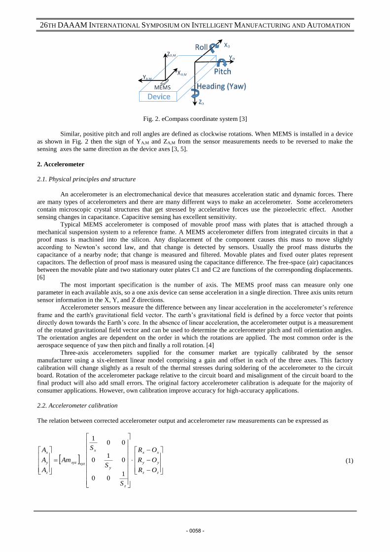
Fig. 2. eCompass coordinate system [3]
Similar, positive pitch and roll angles are defined as clockwise rotations. When MEMS is installed in a device
as shown in Fig. 2 then the sign of YA,M and ZA,M from the sensor measurements needs to be reversed to make the
sensing axes the same direction as the device axes [3, 5].
2. Accelerometer
2.1. Physical principles and structure
An accelerometer is an electromechanical device that measures acceleration static and dynamic forces. There
are many types of accelerometers and there are many different ways to make an accelerometer. Some accelerometers
contain microscopic crystal structures that get stressed by accelerative forces use the piezoelectric effect. Another
sensing changes in capacitance. Capacitive sensing has excellent sensitivity.
Typical MEMS accelerometer is composed of movable proof mass with plates that is attached through a
mechanical suspension system to a reference frame. A MEMS accelerometer differs from integrated circuits in that a
proof mass is machined into the silicon. Any displacement of the component causes this mass to move slightly
according to Newton’s second law, and that change is detected by sensors. Usually the proof mass disturbs the
capacitance of a nearby node; that change is measured and filtered. Movable plates and fixed outer plates represent
capacitors. The deflection of proof mass is measured using the capacitance difference. The free-space (air) capacitances
between the movable plate and two stationary outer plates C1 and C2 are functions of the corresponding displacements.
[6]
The most important specification is the number of axis. The MEMS proof mass can measure only one
parameter in each available axis, so a one axis device can sense acceleration in a single direction. Three axis units return
sensor information in the X, Y, and Z directions.
Accelerometer sensors measure the difference between any linear acceleration in the accelerometer’s reference
frame and the earth's gravitational field vector. The earth’s gravitational field is defined by a force vector that points
directly down towards the Earth’s core. In the absence of linear acceleration, the accelerometer output is a measurement
of the rotated gravitational field vector and can be used to determine the accelerometer pitch and roll orientation angles.
The orientation angles are dependent on the order in which the rotations are applied. The most common order is the
aerospace sequence of yaw then pitch and finally a roll rotation. [4]
Three-axis accelerometers supplied for the consumer market are typically calibrated by the sensor
manufacturer using a six-element linear model comprising a gain and offset in each of the three axes. This factory
calibration will change slightly as a result of the thermal stresses during soldering of the accelerometer to the circuit
board. Rotation of the accelerometer package relative to the circuit board and misalignment of the circuit board to the
final product will also add small errors. The original factory accelerometer calibration is adequate for the majority of
consumer applications. However, own calibration improve accuracy for high-accuracy applications.
2.2. Accelerometer calibration
The relation between corrected accelerometer output and accelerometer raw measurements can be expressed as
zz
yy
xx
z
y
x
xyzxyz
z
y
x
OR
OR
OR
S
S
S
Am
A
A
A
100
01
0
001
(1)
- 0058 -

26TH DAAAM INTERNATIONAL SYMPOSIUM ON INTELLIGENT MANUFACTURING AND AUTOMATION
Where:
A is the corrected reading in X, Y and Z axes.
Am is the 3x3 misalignment matrix between sensor axes and device axes.
S is the sensitivity of each channel.
R is the raw data from the accelerometer.
O is the accelerometer’s zero-g level.
The sensitivities and offsets are constants, so the matrix can be simplified to:
30
20
10
333231
232221
131211
C
C
C
R
R
R
CCC
CCC
CCC
A
A
A
z
y
x
z
y
x
(2)
It is possible rewrite (2) as
(3)
The main goal of accelerometer calibration is to determine 12 parameters [10] from C10 to C33. This is typically
done using the least squares method [3, 4, 5].
The original 6-parameter (gain and offset in each channel) factory calibration can be recomputed to correct for
thermal stresses introduced in the soldering process. Used 12 parameter linear calibration model can correct for
accelerometer package rotation on the circuit board and for cross-axis interference between the accelerometer’s x, y and
z channels [7, 10, 11]. It is possible substitute (3) as
XwY (4)
Where:
Matrix X is calibration parameters. Matrix w is raw data from the accelerometer collected at 6 stationary positions
(when device lays on each side of the device and normalized gravity vector is zero in two axis). For better accuracy is
possible add more stationary positions. Matrix Y is the known normalized gravity vector.
Finally, calculation of 12 calibration parameters by least squares method can be written as
YwwwX TT 1
(5)
3. Magnetometer
A magnetometer is a type of sensor that measures the strength and direction of the local magnetic field. The
magnetic field measured is a combination of both the earth's magnetic field and any magnetic field created by nearby
objects. The accuracy is highly dependent on the calculation and subtraction in software of stray magnetic fields both
within, and in the vicinity of, the magnetometer on the PCB (Printed Circuit Board). By convention, these fields are
divided into those that are fixed (termed Hard-Iron effects) and those that influence or distort geomagnetic field (termed
Soft-Iron effects).
Hard-iron interference magnetic field is normally generated by ferromagnetic materials with permanent
magnetic fields. These materials could be permanent magnets or magnetized iron or steel, for example the metal chassis
or frame of the device, any actual magnets attached such as speakers etc. This interference pattern is unique to the
device and is constant (time invariant). The unwanted magnetic fields are superimposed on the output of the magnetic
sensor measurements of the earth's magnetic field. The effect of this superposition is to bias the magnetic sensor
outputs. If we consider the magnetic data circle (the magnetic field strength in one horizontal direction), hard iron
interference shift the entire circle away from the origin by some amount [9]. The amount is dependent on different
factors and can greatly exceed the geomagnetic field.
A soft-iron interference magnetic field is generated by the items inside the device. They could be current
carrying traces on the PCB or magnetically soft materials. They generate a time varying magnetic field that is
superimposed on the magnetic sensor output in response to the earth's magnetic field. The effect of the soft-iron
distortion is to make a full round rotation circle become a tilted ellipse. The distortion in this case depends on the
direction that the compass is facing. Because of this the distortion cannot be calibrated out with a simple offset. Devices
302010
332313
322212
312111
1
CCC
CCC
CCC
CCC
RRRAAA zyxzyx
- 0059 -

26TH DAAAM INTERNATIONAL SYMPOSIUM ON INTELLIGENT MANUFACTURING AND AUTOMATION
without strong soft-iron interference can simplify calculation, by comprising only the hard-iron offsets and the
geomagnetic field strength.
The relationship between the normalized vector and the magnetic sensor raw data can be expressed as [3]:
zz
yy
xx
cxyz
z
y
x
xxyz
z
y
x
OR
OR
OR
Ms
S
S
S
Mm
M
M
M
3333
100
01
0
001
(6)
Where:
M is the corrected reading in X, Y and Z axes.
Mm is the 3 x 3 misalignment matrix between sensor axes and device axes.
S is the sensitivity of each channel.
R is the raw data from the magnetometer.
Ms is the 3x3 matrix caused by soft iron distortion.
O is the offset caused by hard iron distortion.
The main goal of the magnetometer sensor calibration is to determine parameters to the normalized values could be
obtained at any measurement position [3, 4, 7].
4. eCompass heading calculation
The accelerometer readings provide pitch and roll angle information which is used to correct the magnetometer
data. This allow accurate calculation of the compass heading (yaw) when the device is not held flat. The pitch and roll
angles are computed on assumption that the accelerometer readings result entirely from the compass orientation in the
earth’s gravitational filed. . Fast acceleration (or low-g conditions) influence pitch and roll calculation, so the accuracy
of an electronic compass means static accuracy when the device is without high acceleration. If the PCB remains flat,
then the compass heading could be computed from the arctangent of the ratio of the two horizontal magnetic field
components. In general, the PCB has an arbitrary orientation, the compass heading is a function of all three
accelerometer readings and all three magnetometer readings [5].
Pitch and roll can be calculated by equations [3, 5]:
xAPitch arcsin (7)
cosarcsin
yARoll (8)
Pitch is defined as the angle between the XD axis and the horizontal plane. Roll is defined as the angle between
YD axis and the horizontal plane. The acrsin function has good linearity between about -45° to +45°, so accuracy
degrades when pitch or roll angles exceed this range [3]. All accelerometers are completely insensitive to rotations
about the gravitational field vector and cannot be used to determine such a rotation. The unknown yaw angle represents
the device rotation from magnetic north. Its determination requires a magnetometer sensor.
For he heading calculation, magnetometer measurements need to be normalized by applying calibration
parameters and then by tilt compensation. Tilt compensated magnetic sensor measurements can be obtained as [3, 5]:
sincos 112 zxx MMM (9)
cossincossinsin 1112 zyxy MMMM (10)
Where Mx1 and My1 are normalized magnetic sensor measurements with applied calibration correction. This components can be used for heading angle calculation (yaw angle) [3, 5]:
2
2arctan
x
y
M
MHeading (11)
- 0060 -

26TH DAAAM INTERNATIONAL SYMPOSIUM ON INTELLIGENT MANUFACTURING AND AUTOMATION
Equation (11) is valid for positive values of Mx2 and My2. When Mx2 is positive and My2 component is negative then a negative result is summed with 360°. For the negative value of Mx2 need to be add 180° to heading. Zero value of the Mx2 means that device points to East (90° - My2 is negative value) or West (270° - My2 is positive value). Finally, value should be corrected by declination which is valid at the current location, see Fig. 1.
5. Conclusion
The objective of this work has been to describe an implementation of a tilt compensated eCompass using
accelerometer and magnetometer. The accelerometer sensor output is used by the tilt compensated eCompass
algorithms to compute the roll and pitch angles. These allow tilt correction of the magnetometer data. The
magnetometer readings must be corrected for hard-iron and soft-iron effects.
Although, all MEMS are factory calibrated for common using, it is recommended to perform own calibration to reach a
better accuracy. In future, techniques of calibration can be extended to include temperature dependence by performing
the recalibration at several temperatures and interpolating the fitted calibration parameters to the actual temperature
[11].
6. References
[1] Scouts New Zealand, Compass Basics, New Zealand, 2012.
[2] NOAA, Wandering of the Geomagnetic poles, National Oceanic And Atmospheric Administration, Accessed from: http://www.ngdc.noaa.gov/geomag/GeomagneticPoles.shtml .
[3] STMicroelectronics, AN3192 Application note: Using LSM303DLH for a tilt compensated electronicc compass, 2010: 34p., Accessed from: https://www.pololu.com/file/0J434/LSM303DLH-compass-app-note.pdf
[4] M. Pedley, AN3461 Application note: Tilt Sensing Using a Three-Axis Accelerometer, 2013. Accessed from: http://www.freescale.com/files/sensors/doc/app_note/AN3461.pdf
[5] T. Ozyagcilar, AN4248 Application note: Implementing a Tilt-Compensated eCompass using Accelerometer and Magnetometer Sensors, 2013. Accessed from: http://cache.freescale.com/files/sensors/doc/app_note/AN4248.pdf
[6] F. Cacchione, Mechanical Characterisation and simulation of fracture processes in polysilicon MEMS, PhD Thesis. Politecnicio di Milano, 2007 Accessed from: st.com/web/en/resource/technical/document/white_paper/phd_thesis.pdf.
[7] M. Pedley, AN4399 Application note: High Precision Calibration of a Three-Axis Accelerometer, 2013. Accessed from: http://cache.freescale.com/files/sensors/doc/app_note/AN4399.pdf
[8] D. Willemsen, Compass navigation, 2014, Accessed from: http://www.sailingissues.com/navcourse3.html
[9] D. Skula, New Method for Magnetometer Offset Compensation, Annals of DAAAM for 2010 & procedings, Zadar, 2010, ISBN 978-3-901509-73-5.
[10] S. Stančin, S. Tomažič, Time-and Computation-Efficient Calibration of MEMS 3D Accelerometers and Gyroscopes. Sensors, 2014, 14.8: 14885-14915. Accessed from: http://www.mdpi.com/1424-8220/14/8/14885/pdf.
[11] B. Fang, W. Chou, L. Ding, An optimal calibration method for a MEMS inertial measurement unit. Int. J. Adv. Robot. Syst, 2014, 11.14: 57516. Accessed from: http://cdn.intechopen.com/pdfs-wm/46177.pdf.
- 0061 -