
The indicative Versus The indicative The subjunctive Versus.

TIGER® Diagnostic Report
Diagnostic Analysis Report for
GE Frame 7 Gas Turbine at
Power Plant
Turbine Services Limited Venture Building, Kelvin Campus
West of Scotland Science Park Glasgow, G20 0SP, UK
Tel: +44 (0) 141 945 7000
Email: [email protected]
Web: http://www.turbineserviceslimited.com/
TIGER is a registered trademark of Turbine Services Limited

Table of Contents
EXECUTIVE SUMMARY ................................................................................................................................ 1
INTRODUCTION ............................................................................................................................................ 1
TURBINE PROBLEMS .................................................................................................................................. 2
VIBRATION TRANSDUCER # 3 SENSOR FAULT .................................................................................... 2
HIGH BEARING VIBRATIONS ................................................................................................................... 3
BEARING METAL TEMPERATURE - FAILED THERMOCOUPLES ......................................................... 5
BEARING METAL TEMPERATURE – OVER TEMPERATURE ALARMS ................................................ 6
HYDRAULIC PRESSURE ALARMS .......................................................................................................... 8
FLAME DETECTOR 2 FAULT .................................................................................................................... 9
COMPRESSOR DISCHARGE TEMPERATURE THERMOCOUPLES 1 & 2 .......................................... 10
WHEELSPACE THERMOCOUPLE FAULT ............................................................................................. 11
WHEELSPACE THERMOCOUPLE PROBLEMS .................................................................................... 12
EXHAUST THERMOCOUPLES 1 & 10 - PROBLEMS ............................................................................. 14
EXHAUST TEMPERATURE SPREAD - ADJACENT TC'S ...................................................................... 17
LUBE OIL TEMPERATURE PROBLEMS ................................................................................................ 19
CONTROLLER T VOTING STATUS ALARM ........................................................................................... 21
UNUSUAL SPIKES IN GENERATOR FREQUENCY ............................................................................... 22
TURBINE OSCILLATIONS ....................................................................................................................... 23
ALARMS DUE TO CONTROLLER MAINTENANCE ................................................................................ 28
ALARMS DUE TO R, S & T PROCESSOR DROP-OUTS ........................................................................ 29
EXHAUST THERMOCOUPLE 17 FAILURE ............................................................................................ 31
EXHAUST TEMPERATURE SPREAD TRIP ............................................................................................ 33
EXHAUST SPREAD PROBLEMS ON STARTUP .................................................................................... 36
EXHAUST OVER TEMPERATURE STARTUP TRIP............................................................................... 38
LIQUID FUEL PROBLEMS DURING FUEL TRANSFER ......................................................................... 41
TRIP ON COMPRESSOR BLEED VALVE 2 TROUBLE .......................................................................... 44
TRIP DUE TO LOW GAS PRESSURE AND NO LIQUID FUEL FLOW .................................................... 45
BAD SIGNAL ON BEARING TRANSDUCER 3 ........................................................................................ 50
LIQUID FUEL CONTROL FAULT ............................................................................................................. 51
HIGH WHEEL SPACE TEMPERATURE ALARMS .................................................................................. 53
GAS FUEL P2 PRESSURE INSTABILITY ............................................................................................... 55
CONTROLLER COMPARTMENT HIGH TEMPERATURE ALARMS ...................................................... 57
GENERATOR EXCITER RECTIFIER COOLING FAN ALARMS ............................................................. 59
GENERATOR AND GRID - FREQUENCY AND VOLTAGE DROPOUTS ............................................... 60
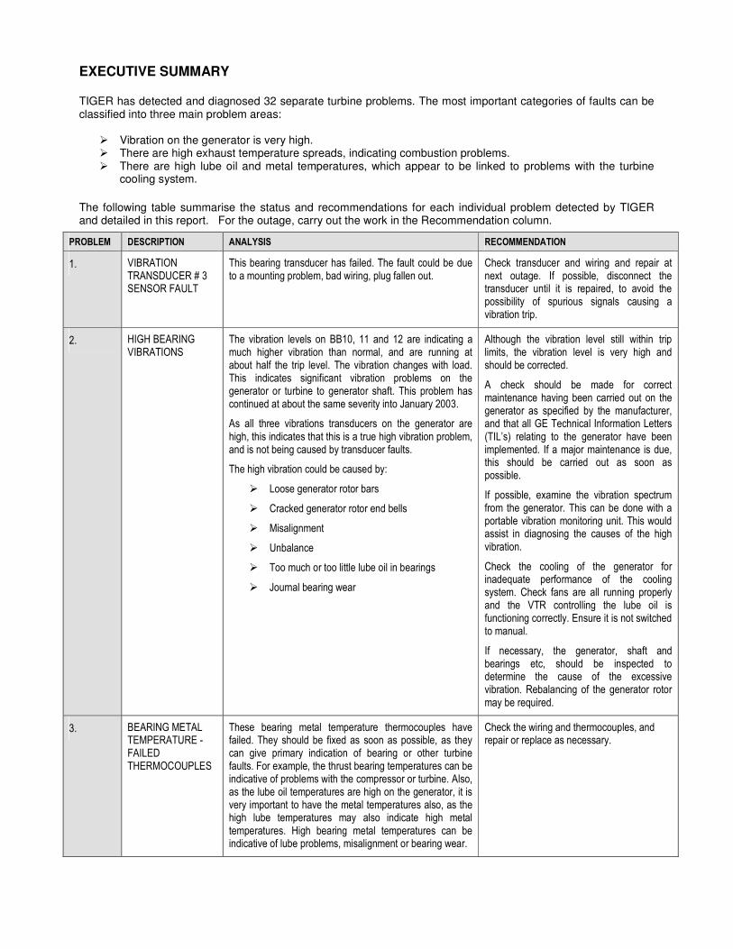
EXECUTIVE SUMMARY
TIGER has detected and diagnosed 32 separate turbine problems. The most important categories of faults can be classified into three main problem areas:
� Vibration on the generator is very high. � There are high exhaust temperature spreads, indicating combustion problems. � There are high lube oil and metal temperatures, which appear to be linked to problems with the turbine
cooling system.
The following table summarise the status and recommendations for each individual problem detected by TIGER and detailed in this report. For the outage, carry out the work in the Recommendation column.
PROBLEM DESCRIPTION ANALYSIS RECOMMENDATION
1. VIBRATION TRANSDUCER # 3 SENSOR FAULT
This bearing transducer has failed. The fault could be due to a mounting problem, bad wiring, plug fallen out.
Check transducer and wiring and repair at next outage. If possible, disconnect the transducer until it is repaired, to avoid the possibility of spurious signals causing a vibration trip.
2. HIGH BEARING VIBRATIONS
The vibration levels on BB10, 11 and 12 are indicating a much higher vibration than normal, and are running at about half the trip level. The vibration changes with load. This indicates significant vibration problems on the generator or turbine to generator shaft. This problem has continued at about the same severity into January 2003.
As all three vibrations transducers on the generator are high, this indicates that this is a true high vibration problem, and is not being caused by transducer faults.
The high vibration could be caused by:
� Loose generator rotor bars
� Cracked generator rotor end bells
� Misalignment
� Unbalance
� Too much or too little lube oil in bearings
� Journal bearing wear
Although the vibration level still within trip limits, the vibration level is very high and should be corrected.
A check should be made for correct maintenance having been carried out on the generator as specified by the manufacturer, and that all GE Technical Information Letters (TIL’s) relating to the generator have been implemented. If a major maintenance is due, this should be carried out as soon as possible.
If possible, examine the vibration spectrum from the generator. This can be done with a portable vibration monitoring unit. This would assist in diagnosing the causes of the high vibration.
Check the cooling of the generator for inadequate performance of the cooling system. Check fans are all running properly and the VTR controlling the lube oil is functioning correctly. Ensure it is not switched to manual.
If necessary, the generator, shaft and bearings etc, should be inspected to determine the cause of the excessive vibration. Rebalancing of the generator rotor may be required.
3. BEARING METAL TEMPERATURE - FAILED THERMOCOUPLES
These bearing metal temperature thermocouples have failed. They should be fixed as soon as possible, as they can give primary indication of bearing or other turbine faults. For example, the thrust bearing temperatures can be indicative of problems with the compressor or turbine. Also, as the lube oil temperatures are high on the generator, it is very important to have the metal temperatures also, as the high lube temperatures may also indicate high metal temperatures. High bearing metal temperatures can be indicative of lube problems, misalignment or bearing wear.
Check the wiring and thermocouples, and repair or replace as necessary.

4. BEARING METAL TEMPERATURE – OVER TEMPERATURE ALARMS
This thermocouple was reading very high. This could have been due to thermocouple, bearing or lube problems. As the other thermocouple in the pair has failed the reading of thermocouple 1 cannot be checked against the other reading. The lube drain temperatures for bearings 1, 2 & 3 are all very similar in levels and behaviour, so this may also indicate that the bearing metal temperature thermocouple reading is inaccurate. The vibration levels on bearing 3 (BB4 & BB5) are also higher than bearing 1 (BB1 & BB2), but still fairly low. This would also tend to indicate that there are no significant bearing problems occurring. The failure of the thermocouple on the 4th November would also tend to support this view. This also indicates the importance of having all thermocouples working, in order to be sure if temperature problems are real, or simply due to inaccurate thermocouple readings.
The most likely cause is therefore a faulty thermocouple. This could be due to a short circuit in the thermocouple tube (which is a metal filled tube filled with mineral insulation), or the thermocouple tube is contacting other hot metal parts. It is probably detecting a hot air temperature inside the turbine, and not the actual metal temperature.
Check thermocouples 1 and 2 and wiring, and repair as required. If thermocouples 1 and 2 still indicate high temperatures. If they do, check the no 3 bearing and the associated lube system.
5. HYDRAULIC PRESSURE ALARMS
These messages indicate that the hydraulic oil pressure is low. Information from site has indicated that the cause of the low pressure alarms is not known. If they do indicate pressure problems, this could significantly affect the operation of the turbine, causing control problems or even a turbine trip. The most likely cause is due to a faulty pressure sensor. This could be due to bad calibration, or sticky pressure bellows. Could also be due to incorrect pressure regulator adjustment on the hydraulic supply pump.
Check for a faulty hydraulic pressure sensor. This could be due to bad calibration, or sticky pressure bellows. Check the pressure regulator adjustment on the hydraulic supply pump. Adjust and/or repair as required.
6. FLAME DETECTOR 2 FAULT
This flame detector was continuously flickering. This continued up to the outage in November, but worked correctly after this. This was probably due to a faulty detector.
The detector should be cleaned up and tested. If faulty, it should be replaced.
7. COMPRESSOR DISCHARGE TEMPERATURE THERMOCOUPLES 1 & 2
There is a higher than normal temperature difference between these thermocouples. The two compressor discharge thermocouples differ considerably at one stage by around 30 Deg C, particularly as the GT increases power to base load. The temperature difference is generally less at around 20 Deg C, and has persisted into January 2003. This probably indicates a thermocouple problem.
This could be caused by:
� Bad thermocouple insertion.
� Bad calibration.
� Other thermocouple faults – cold junction or short circuit.
As the temperature offsets are not seen in the exhaust temperatures, this is more likely to be a thermocouple problem. Also, one thermocouple (CTDA1) does not change as much as the other, and this also indicates a problem with this thermocouple, possibly a cold junction offset effect.
Remove and check both thermocouples and wiring, and repair or re-calibrate as required. If the problems persist, check the diffusers on the last stage of the compressor.
8. WHEELSPACE THERMOCOUPLE FAULT
This wheelspace temperature thermocouple has failed.
Check thermocouple and wiring and repair as required. Should be replaced when convenient.
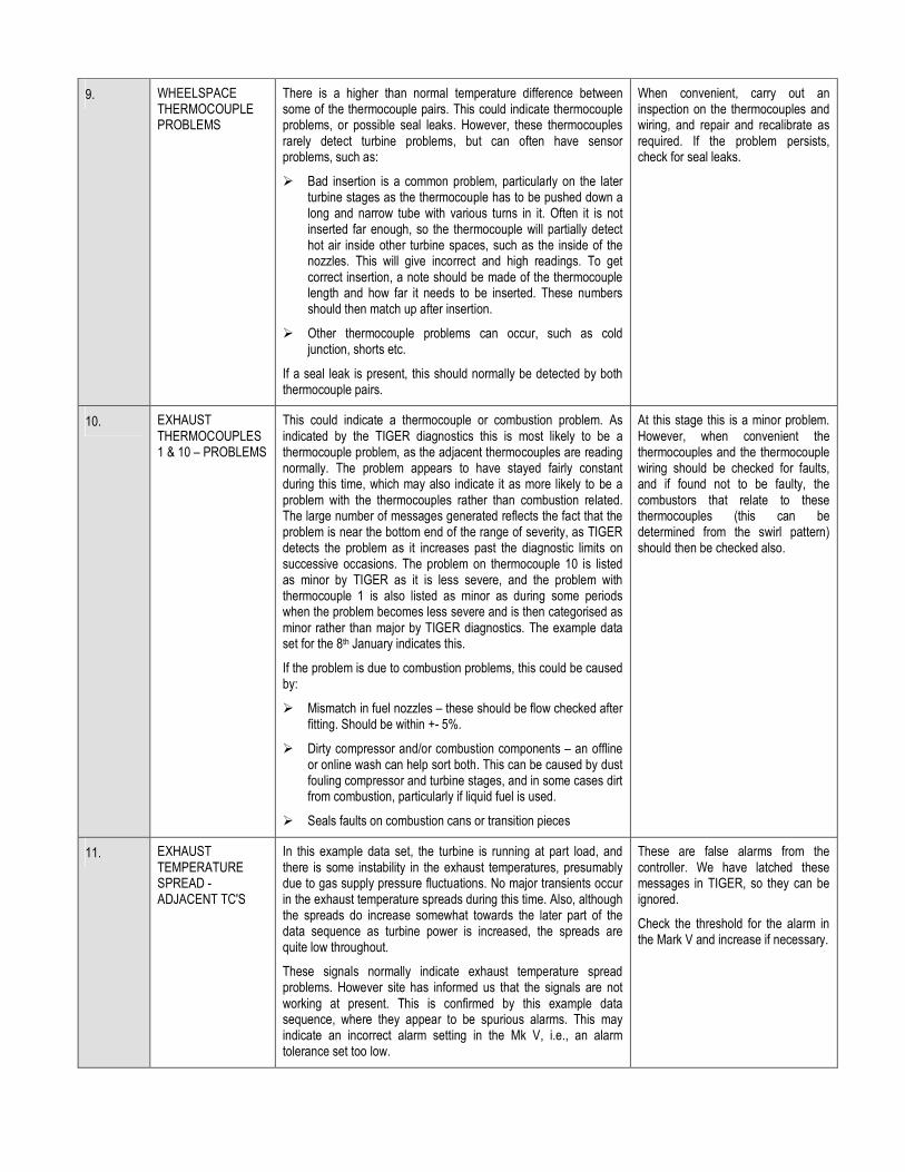
9. WHEELSPACE THERMOCOUPLE PROBLEMS
There is a higher than normal temperature difference between some of the thermocouple pairs. This could indicate thermocouple problems, or possible seal leaks. However, these thermocouples rarely detect turbine problems, but can often have sensor problems, such as:
� Bad insertion is a common problem, particularly on the later turbine stages as the thermocouple has to be pushed down a long and narrow tube with various turns in it. Often it is not inserted far enough, so the thermocouple will partially detect hot air inside other turbine spaces, such as the inside of the nozzles. This will give incorrect and high readings. To get correct insertion, a note should be made of the thermocouple length and how far it needs to be inserted. These numbers should then match up after insertion.
� Other thermocouple problems can occur, such as cold junction, shorts etc.
If a seal leak is present, this should normally be detected by both thermocouple pairs.
When convenient, carry out an inspection on the thermocouples and wiring, and repair and recalibrate as required. If the problem persists, check for seal leaks.
10. EXHAUST THERMOCOUPLES 1 & 10 – PROBLEMS
This could indicate a thermocouple or combustion problem. As indicated by the TIGER diagnostics this is most likely to be a thermocouple problem, as the adjacent thermocouples are reading normally. The problem appears to have stayed fairly constant during this time, which may also indicate it as more likely to be a problem with the thermocouples rather than combustion related. The large number of messages generated reflects the fact that the problem is near the bottom end of the range of severity, as TIGER detects the problem as it increases past the diagnostic limits on successive occasions. The problem on thermocouple 10 is listed as minor by TIGER as it is less severe, and the problem with thermocouple 1 is also listed as minor as during some periods when the problem becomes less severe and is then categorised as minor rather than major by TIGER diagnostics. The example data set for the 8th January indicates this.
If the problem is due to combustion problems, this could be caused by:
� Mismatch in fuel nozzles – these should be flow checked after fitting. Should be within +- 5%.
� Dirty compressor and/or combustion components – an offline or online wash can help sort both. This can be caused by dust fouling compressor and turbine stages, and in some cases dirt from combustion, particularly if liquid fuel is used.
� Seals faults on combustion cans or transition pieces
At this stage this is a minor problem. However, when convenient the thermocouples and the thermocouple wiring should be checked for faults, and if found not to be faulty, the combustors that relate to these thermocouples (this can be determined from the swirl pattern) should then be checked also.
11. EXHAUST TEMPERATURE SPREAD - ADJACENT TC'S
In this example data set, the turbine is running at part load, and there is some instability in the exhaust temperatures, presumably due to gas supply pressure fluctuations. No major transients occur in the exhaust temperature spreads during this time. Also, although the spreads do increase somewhat towards the later part of the data sequence as turbine power is increased, the spreads are quite low throughout.
These signals normally indicate exhaust temperature spread problems. However site has informed us that the signals are not working at present. This is confirmed by this example data sequence, where they appear to be spurious alarms. This may indicate an incorrect alarm setting in the Mk V, i.e., an alarm tolerance set too low.
These are false alarms from the controller. We have latched these messages in TIGER, so they can be ignored.
Check the threshold for the alarm in the Mark V and increase if necessary.

12. LUBE OIL TEMPERATURE PROBLEMS
The problem with the lube oil header temperature was first indicated by TIGER warning messages on the 21st October, and this problem also causes controller alarms to occur, as the temperature rises. On the 30th October, first TIGER generates warning messages as the temperature rises above the TIGER limit of 58 Deg C with the ambient temperature increase, and then controller alarms occur. The controller alarm clears when the turbine is shutdown. These high temperatures could also be related to the high vibration levels on the generator. There is also the possibility that this thermocouple is not reading accurately.
The controller alarm (L30LOA) has not occurred since 22nd November 2002. Examination of the monthly trend graph for November indicates that this is probably to the falling ambient temperatures during the month.
This is a significant problem. Lube oil temps should be in the range 54 – 70 Deg C (lube oil header temperature), but they are higher than this and vary with ambient temperatures rather than staying constant. If turbine is too hot, this can cause problems with the bearings including problems with misalignment, particularly at the generator end of the turbine, where the support legs can get too hot and distort.
The high lube temperatures may be caused by cooling system problems. This could be caused by clogging of radiators (e.g, sand) or cooling fan problems. There is also a low water cooling level alarm present. It could also be caused by water leakage at the three way water control valve. Alternatively a manual lock may have been applied to the valve so it is not controlling water flow as ambient temperatures change. Or, temperature control of the cooling system is not working for some other reason.
Check the lube oil system and lube oil water cooling system, as a further increase in lube temperatures could lead to a trip, and possibly extra wear on the turbine. Check the water cooling system for:
� clogging of radiators (i.e. sand)
� cooling fan problems
� cooling water reservoir level
� water leakage at the three way water control valve
� possible manual lock on the control valve
� malfunction of the temperature control of the cooling water system
13. CONTROLLER T VOTING STATUS ALARM
This alarm (L3VOTE-T) has continued to occur regularly. The alarm should be monitored, as an increase in frequency of occurrence may indicate controller problems. Could be due to bad connections in the controller or cables, or dust inside the controller.
Check relevant controller cards and connections and clean the controller boards and housing with compressed air.
14. UNUSUAL SPIKES IN GENERATOR FREQUENCY
These small spikes in the generator frequency continue to occur periodically. This is may be due instrumentation noise, or possibly to grid frequency instability which may occur faster than the TIGER sample time of 1 second. It could also indicate generator problems. At this stage this is a minor problem, either due to electrical noise or grid instability.
No immediate action, but monitor the incidence and severity of grid voltage and frequency changes. If these become severe, checks should also be carried out on the generator.
15. TURBINE OSCILLATIONS
Although these oscillations are relatively small, they are abnormal. The thermal cycling caused by the oscillations will cause increased wear and tear to the hot gas path and other components and reduce component life. These oscillations will also reduce turbine performance.
It was possible that these turbine oscillations may be caused by grid voltage oscillations. However, since this happens at FSNL it is more likely to be caused by another internal problem, such as fuel control or gas fuel pressure problems.
These oscillations are a significant problem, and are most likely due to fuel control problems. This could be due to controller tuning, hydraulics problems or gas fuel valve component wear. Worn valves are often the cause of this, and even if they are still within the manufacturers tolerance limits, worn valves can cause this type of poor fuel control to occur.
When convenient, try auto tuning the controller and fuel valve system. If this fails, a manual controller and fuel valve tuning could be tried. If this fails, then check the operation of the gas fuel system and the pressure stability of the gas fuel supply. Overhaul and/or replace any worn or faulty fuel valve components as required.

16. ALARMS DUE TO CONTROLLER MAINTENANCE
This occurred when the turbine was stopped. The likely cause of these alarms was maintenance actions being carried out on the turbine controller, and if this is the case they can be ignored.
Check the maintenance log for the controller, to determine if these faults were false alarms due to maintenance activities. Note, the controller should be powered off before any maintenance is carried out on it.
17. ALARMS DUE TO R, S & T PROCESSOR DROP-OUTS
TIGER diagnostics has detected drop outs of the R, S & T turbine controller processors by detecting the signal loss values of the three interleaved sets of exhaust thermocouples. These drop outs could be due to bad connections within the controller. This may indicate that the controller is becoming more unreliable. There were over 1000 of these incidents recorded during 1st two weeks of January 2003. This is a serious problem as this could cause a turbine trip, or prevent a startup. The drop-outs could be caused by bad connections in the controller or cables, or faults in the controller electronics.
Check the relevant controller cards and connections and clean the controller boards and housing with compressed air. If necessary, replace any faulty controller processor components.
18. EXHAUST THERMOCOUPLE 17 FAILURE
Thermocouple 17 starts failing at around 22:21:06. This causes the high spread value. It finally fails completely about five minutes later at around 22:25:09. This could be caused by a short circuit in the thermocouple, giving a spurious low reading. There could also be a short circuit in the termination box or in the wiring connections to the controller.
Check the wiring and thermocouple. Check for a short circuit in the thermocouple or in the termination box or in the wiring connections to the controller. Repair or replace as necessary.
19. EXHAUST TEMPERATURE SPREAD TRIP
Initially exhaust thermocouple 17 is reading low and there is a high spread. Eventually, 15 and 16 also become low, and this causes the trip. As there is no change in power levels, this is probably due to a thermocouple problem. However, three thermocouples reading low simultaneously is normally indicative of combustion problems. During this time, there is significant instability in the gas fuel control valves, with all major parameters such as power, exhaust temperature and P2 pressure oscillating. It is possible that these problems could also be linked to the cause of the trip, although it is more likely that that the problem is related to the incidents on the 10th and 13th of November where thermocouple 17 was reading cold and also failed (on the 10th). This could be caused by a short circuit in the thermocouples, giving a spurious low reading. There could also be a short circuits in the termination box or in the wiring connections to the controller.
Check the wiring and thermocouple. Check for a short circuit in the thermocouple or in the termination box or in the wiring connections to the controller. Repair or replace as necessary. The termination is the most likely location.
20. EXHAUST SPREAD PROBLEMS ON STARTUP
This could have been due to a bad thermocouple or combustion problem. This incident was probably related to the previous one on the 10th November where thermocouple 17 failed, so as indicated by TIGER diagnostics it appeared to be due to a thermocouple problem. This could be caused by a short circuit in the thermocouple, giving a spurious low reading. There could also be a short circuit in the termination box or in the wiring connections to the controller.
Check the wiring and thermocouple. Check for a short circuit in the thermocouple or in the termination box or in the wiring connections to the controller. Repair or replace as necessary.
21. EXHAUST OVER TEMPERATURE STARTUP TRIP
TIGER detects over temperature problems, and the turbine trips on over temperature. TIGER also indicates spread problems, which also become very severe. There are also indications of poor flame or loss of flame on some combustors, as one flame detector is either low or has transient drop outs. This would confirm that combustion is poorly established or unstable on one or more combustors, causing the bad spread. All this indicates a serious combustion problem occurred.
Check that all igniters are functioning correctly.
If the problem happens again, do this: Fire on liquid and then do a partial transfer to gas, running on mixed fuel with around 5% gas and 95% liquid. This should then ensure any spurious distillates in the gas fuel get burnt of

It appears that the turbine is not cross–firing at some points, and this indicates one or more igniters could be faulty.
There was very uneven combustion followed by delayed flame out after the gas fuel was shutdown. This is a very serious problem, and could be caused by liquid distillate fuel being present in the gas fuel during startup. Possible causes are:
� Poor gas quality.
� Failure of gas scrubbers (if any are being used).
� Gas fuel not being heated to the correct temperature (check gas fuel heaters).
� Build up over time of distillates in the gas fuel lines.
� Faulty fuel nozzles.
� Faulty combustion cans or transition pieces.
A temperature of greater than 600 Degrees C in the exhaust (in this case 900 Deg C was seen) probably indicates a fire in the exhaust plenum, due to condensate gas being forced through the turbine stage and then falling down into the plenum and igniting.
It is possible that the turbine may have been damaged by these 7 repeated bad startups detected by TIGER diagnostics.
in a harmless and controlled manner.
If the problem persists, check for faults in the fuel nozzles, or failed seals in the combustion cans and/or transition pieces.
22. LIQUID FUEL PROBLEMS DURING FUEL TRANSFER
There is a major spike in the flow, followed by smaller transients. These are not in response to fuel demand. This may indicate problems in the liquid fuel system. The subsequent fuel transfer is successful, however as can be seen from the spread screen, the combustion on liquid fuel is poor, with an increase in spreads and a flame out indicated on one can. Based on this, It is possible that a liquid fuel startup or prolonged liquid fuel operation would fail
Check and overhaul the liquid fuel system as needed.
23. TRIP ON COMPRESSOR BLEED VALVE 2 TROUBLE
This is a minor problem, and occurs as one of the compressor bleed valves has too long delay in opening after the controller open command. This may indicate that the bleed valve is sticking.
The compressor bleed valves should be exercised to remove any unwanted friction in the valves. The air operated pistons should be checked, and new seals fitted to these if required
24. TRIP DUE TO LOW GAS PRESSURE AND NO LIQUID FUEL FLOW
During the fuel transfer there are problems with low and unstable gas fuel pressure. However, critically there is no liquid fuel supply, so the turbine eventually trips on flame out as the gas fuel is reduced but no liquid fuel is supplied to replace it. This was an operational problem, as it appears the manual stop valve for the liquid fuel was off when a fuel transfer was attempted. Hence it failed.
Ensure that all liquid fuel isolation valves are open before attempting a liquid fuel start or gas to liquid fuel transfer.
25. BAD SIGNAL ON BEARING TRANSDUCER 3
There is a very large jump in the BB3 overall vibration level after the trip during the run down. BB3 is not working (see previous incident on this), but during the run down it appears to go from an invalid value to a very large valid value. This is consistent with a transducer malfunction, but if this occurred during normal running, this could cause a spurious turbine trip as a large valid value may be above the vibration trip limit and could activate a high vibration protection trip. This may have been caused by a loose transducer, which was disturbed during the turbine shutdown, generating a spurious signal. Could also be due to loose wiring.
The mounting and wiring for bearing transducer 3 should be checked and repaired as required. If this is not possible, the transducer should be wired out to avoid the possibility of a spurious vibration trip occurring.
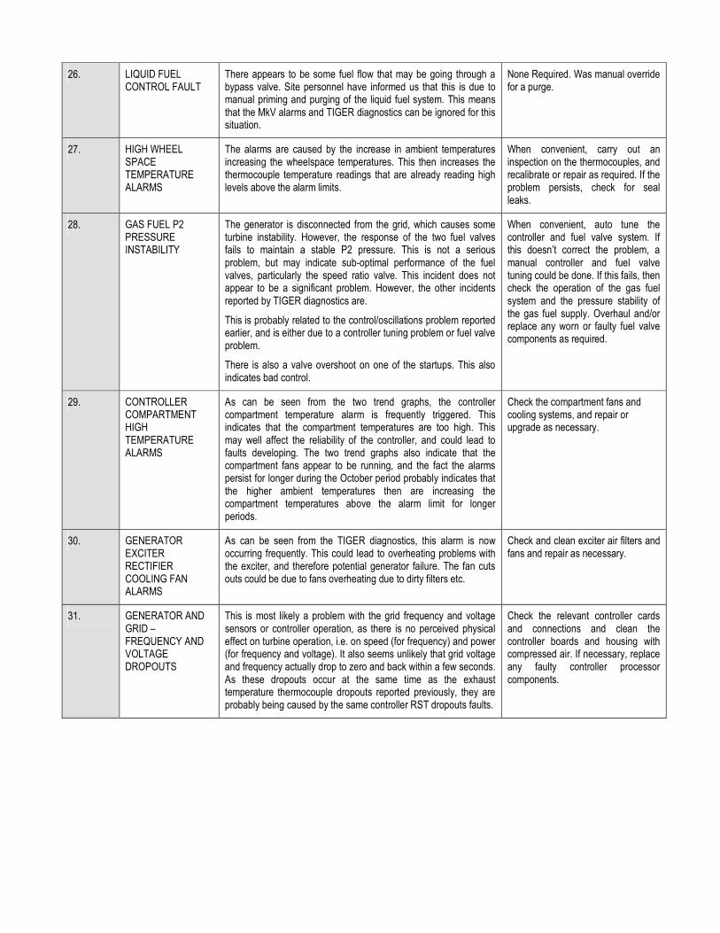
26. LIQUID FUEL CONTROL FAULT
There appears to be some fuel flow that may be going through a bypass valve. Site personnel have informed us that this is due to manual priming and purging of the liquid fuel system. This means that the MkV alarms and TIGER diagnostics can be ignored for this situation.
None Required. Was manual override for a purge.
27. HIGH WHEEL SPACE TEMPERATURE ALARMS
The alarms are caused by the increase in ambient temperatures increasing the wheelspace temperatures. This then increases the thermocouple temperature readings that are already reading high levels above the alarm limits.
When convenient, carry out an inspection on the thermocouples, and recalibrate or repair as required. If the problem persists, check for seal leaks.
28. GAS FUEL P2 PRESSURE INSTABILITY
The generator is disconnected from the grid, which causes some turbine instability. However, the response of the two fuel valves fails to maintain a stable P2 pressure. This is not a serious problem, but may indicate sub-optimal performance of the fuel valves, particularly the speed ratio valve. This incident does not appear to be a significant problem. However, the other incidents reported by TIGER diagnostics are.
This is probably related to the control/oscillations problem reported earlier, and is either due to a controller tuning problem or fuel valve problem.
There is also a valve overshoot on one of the startups. This also indicates bad control.
When convenient, auto tune the controller and fuel valve system. If this doesn’t correct the problem, a manual controller and fuel valve tuning could be done. If this fails, then check the operation of the gas fuel system and the pressure stability of the gas fuel supply. Overhaul and/or replace any worn or faulty fuel valve components as required.
29. CONTROLLER COMPARTMENT HIGH TEMPERATURE ALARMS
As can be seen from the two trend graphs, the controller compartment temperature alarm is frequently triggered. This indicates that the compartment temperatures are too high. This may well affect the reliability of the controller, and could lead to faults developing. The two trend graphs also indicate that the compartment fans appear to be running, and the fact the alarms persist for longer during the October period probably indicates that the higher ambient temperatures then are increasing the compartment temperatures above the alarm limit for longer periods.
Check the compartment fans and cooling systems, and repair or upgrade as necessary.
30. GENERATOR EXCITER RECTIFIER COOLING FAN ALARMS
As can be seen from the TIGER diagnostics, this alarm is now occurring frequently. This could lead to overheating problems with the exciter, and therefore potential generator failure. The fan cuts outs could be due to fans overheating due to dirty filters etc.
Check and clean exciter air filters and fans and repair as necessary.
31. GENERATOR AND GRID – FREQUENCY AND VOLTAGE DROPOUTS
This is most likely a problem with the grid frequency and voltage sensors or controller operation, as there is no perceived physical effect on turbine operation, i.e. on speed (for frequency) and power (for frequency and voltage). It also seems unlikely that grid voltage and frequency actually drop to zero and back within a few seconds. As these dropouts occur at the same time as the exhaust temperature thermocouple dropouts reported previously, they are probably being caused by the same controller RST dropouts faults.
Check the relevant controller cards and connections and clean the controller boards and housing with compressed air. If necessary, replace any faulty controller processor components.

Diagnostics Analysis Report for Power Plant Unit 1
-1-
INTRODUCTION
These are findings based on the analysis of results from data sets processed by TIGER for the period 26th
October 2002 – 8th
January 2003. This includes all the findings from the previous two reports, plus additional findings based on the latest data available. The findings from the previous two reports incorporated here have also been updated in the light of the latest information available. TIGER diagnostic messages are included where appropriate, in the original colour code format. Graphs and screen dumps are also included in some cases. In cases where problems and faults have multiple occurrences, we typically select one or maybe two examples for the report. More analysis of some of the incidents reported may be required, and there may be a requirement for maintenance action in some cases. For each incident, an analysis and recommendation is made. In some cases, faults have been fixed since this report was initially compiled. This is indicated where this has occurred.

Diagnostics Analysis Report for Power Plant Unit 1
-2-
TURBINE PROBLEMS
1. VIBRATION TRANSDUCER # 3 SENSOR FAULT This bearing vibration transducer has been faulty through out the sample data set period. Bearing screen with failed bearing vibration transducer 3 (BB3) indicated.
TIGER Diagnostic Messages 05:58:50 08/01/2003 § Vibration transducer # 3 sensor problem. Limit -1.00 05:58:50 08/01/2003 § Vibration fault - transducer input #3 [L39VF-3] not in expected state [actual 1 expected 0]
Analysis This bearing transducer has failed. The fault could be due to a mounting problem, bad wiring, plug fallen out etc. Recommendation Check transducer and wiring and repair at next outage. If possible, disconnect the transducer until it is repaired, to avoid the possibility of spurious signals causing a vibration trip.

Diagnostics Analysis Report for Power Plant Unit 1
-3-
2. HIGH BEARING VIBRATIONS The vibration screen indicates that the generator bearings BB10, 11 and 12 are indicating a high vibration level.
TIGER Diagnostic Messages 16:35:44 21/10/2002 § Vibration transducer # 10 [BB10] too high. Limit 5.00 mm/s 16:35:44 21/10/2002 § Vibration transducer # 11 [BB11] too high. Limit 5.00 mm/s 16:35:44 21/10/2002 § Vibration transducer # 12 [BB12] too high. Limit 5.00 mm/s
Analysis The vibration levels on BB10, 11 and 12 are indicating a much higher vibration than normal, and are running at about half the trip level. This indicates significant vibration problems on the generator or turbine to generator shaft. This problem has continued at about the same severity into January 2003. As all three vibrations transducers on the generator are high, this indicates that this is a real high vibration problem, and is not being caused by transducer faults. The high vibration could be caused by:
� Loose generator rotor bars � Cracked generator rotor end bells � Misalignment � Unbalance � Too much or too little lube oil in bearings � Journal bearing wear
Diagnostics Analysis Report for Power Plant Unit 1
-4-
Recommendation Although the vibration level still within trip limits, the vibration level is very high and should be corrected. A check should be made for correct maintenance having been carried out on the generator as specified by the manufacturer, and that all GE Technical Information Letters (TIL’s) relating to the generator have been implemented. If a major maintenance is due, this should be carried out as soon as possible. If possible, examine the vibration spectrum from the generator. This can be done with a portable vibration monitoring unit. This would assist in diagnosing the causes of the high vibration. Check the cooling of the generator and for inadequate performance of the cooling system. Check fans are all running properly and the variable temperature regulator (VTR) controlling the lube oil is functioning correctly. If necessary, the generator, shaft and bearings etc, should be inspected to determine the cause of the excessive vibration. Rebalancing of the generator rotor may be required.

Diagnostics Analysis Report for Power Plant Unit 1
-5-
3. BEARING METAL TEMPERATURE - FAILED THERMOCOUPLES These thermocouples have been faulty throughout the sample data set period. Bearing screen with failed thermocouples indicated.
TIGER Diagnostic Messages 14:02:00 08/01/2003 § Bearing metal temperature turbine journal #1 tc 1 sensor problem. Limit 0.00 14:02:00 08/01/2003 § Bearing metal temperature turbine journal #1 tc 2 sensor problem. Limit 0.00 14:02:00 08/01/2003 § Bearing metal temperature turbine journal #2 tc 1 sensor problem. Limit 0.00 14:02:00 08/01/2003 § Bearing metal temperature turbine journal #2 tc 2 sensor problem. Limit 0.00 14:02:00 08/01/2003 Bearing metal temperature turbine journal #3 tc 1 sensor problem. Limit 0.00 14:02:00 08/01/2003 Bearing metal temperature turbine journal #3 tc 2 sensor problem. Limit 0.00 14:02:00 08/01/2003 § Bearing metal thermocouple #1 sensor problem. Limit 0.00 14:02:00 08/01/2003 § Bearing metal thermocouple #2 sensor problem. Limit 0.00 14:02:00 08/01/2003 § Bearing metal thermocouple #1 sensor problem. Limit 0.00
Analysis These bearing metal temperature thermocouples have failed. They should be fixed as soon as possible, as they can give primary indication of bearing or other turbine faults. For example, the thrust bearing temperatures can be indicative of problems with the compressor or turbine. Also, as the lube oil temperatures are high on the generator, it is very important to have the metal temperatures also, as the high lube temperatures may also indicate high metal temperatures. High bearing metal temperatures can be indicative of lube problems, misalignment or bearing wear. Recommendation Check the wiring and thermocouples, and repair or replace as necessary.

Diagnostics Analysis Report for Power Plant Unit 1
-6-
4. BEARING METAL TEMPERATURE – OVER TEMPERATURE ALARMS This controller alarm is occurring frequently. TIGER diagnostics also detects high temperatures on this thermocouple. The problem appears to be triggered by the high temperatures on turbine journal bearing 3. This is indicated by the trend graph for the 29
th October 2002 and a data graph for around 10:40 below.
Daily trend graph showing overtemperature alarm and bearing 3 metal temperature.
Daily trend graph showing turbine bearings lube drain temperatures.
Daily trend graph showing turbine bearing 3 vibration.
Graph showing onset of over temperature alarm and bearing 3 metal temperature.

Diagnostics Analysis Report for Power Plant Unit 1
-7-
TIGER Diagnostic Messages 10:43:27 29/10/2002 Bearing metal temperature. turbine journal #3 TC1 [BTJ3-1] too high. Limit 100.00 degC 10:43:47 29/10/2002 § Bearing metal OVERTEMP alarm [L30BTA] change from 0 to 1 10:43:51 29/10/2002 § Bearing metal OVERTEMP alarm [L30BTA] change from 0 to 1 10:43:54 29/10/2002 § Bearing metal OVERTEMP alarm [L30BTA] change from 0 to 1 10:44:01 29/10/2002 § Bearing metal OVERTEMP alarm [L30BTA] change from 0 to 1 10:44:12 29/10/2002 § Bearing metal OVERTEMP alarm [L30BTA] change from 0 to 1 10:44:15 29/10/2002 § Bearing metal OVERTEMP alarm [L30BTA] change from 0 to 1 10:44:22 29/10/2002 § Bearing metal OVERTEMP alarm [L30BTA] change from 0 to 1 10:44:53 29/10/2002 § Bearing metal OVERTEMP alarm [L30BTA] change from 0 to 1 10:44:59 29/10/2002 § Bearing metal OVERTEMP alarm [L30BTA] change from 0 to 1
This thermocouple failed on the 4
th November, as can be seen from the daily trend.
Daily trend graph showing bearing 3 metal temperature.
Analysis This thermocouple was reading very high. This could have been due to thermocouple, bearing or lube problems. As the other thermocouple in the pair has failed the reading of thermocouple 1 cannot be checked against the other reading. The lube drain temperatures for bearings 1, 2 & 3 are all very similar in levels and behaviour, so this may also indicate that the bearing metal temperature thermocouple reading is inaccurate. The vibration levels on bearing 3 (BB4 & BB5) are also higher than bearing 1 (BB1 & BB2), but still fairly low. This would also tend to indicate that there are no significant bearing problems occurring. The failure of the thermocouple on the 4
th November would also tend to support this view. This also indicates
the importance of having all thermocouples working, in order to be sure if temperature problems are real, or simply due to inaccurate thermocouple readings. The most likely cause is therefore a faulty thermocouple. This could be due to a short circuit in the thermocouple tube (which is a metal filled tube filled with mineral insulation), or the thermocouple tube is contacting other hot metal parts. It is probably detecting a hot air temperature inside the turbine, and not the actual metal temperature. Recommendation Check thermocouples 1 and 2 and wiring and repair as required. If thermocouples 1 and 2 still indicate high temperatures, then check the no 3 bearing and the associated lube system.

Diagnostics Analysis Report for Power Plant Unit 1
-8-
5. HYDRAULIC PRESSURE ALARMS TIGER Diagnostic Messages 16:35:44 21/10/2002 § Hydraulic oil pressure is not ok 16:35:44 21/10/2002 § Inlet guide vanes - hydraulic supply pressure too low 16:35:44 21/10/2002 § AUX hydraulic oil pump motor running [L52HQ-ALM] not in expected state [actual 1 expected 0] 16:35:44 21/10/2002 § Hydraulic supply pressure low [L63HQ1L-ALM] not in expected state [actual 1 expected 0]
Analysis These messages indicate that the hydraulic oil pressure is low. Information from site has indicated that the cause of the low pressure alarms is not known. If they do indicate pressure problems, this could significantly affect the operation of the turbine, causing control problems or even a turbine trip. The most likely cause is due to a faulty pressure sensor. This could be due to bad calibration, or sticky pressure bellows. Could also be due to incorrect pressure regulator adjustment on the hydraulic supply pump. Recommendation Check for a faulty hydraulic pressure sensor. This could be due to bad calibration, or sticky pressure bellows. Check the pressure regulator adjustment on the hydraulic supply pump. Adjust and/or repair as required.
Diagnostics Analysis Report for Power Plant Unit 1
-9-
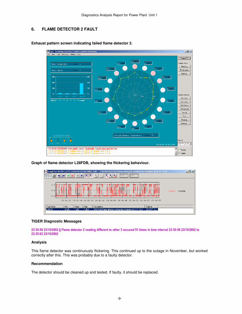
6. FLAME DETECTOR 2 FAULT
Exhaust pattern screen indicating failed flame detector 2.
Graph of flame detector L28FDB, showing the flickering behaviour.
TIGER Diagnostic Messages 23:30:56 23/10/2002 § Flame detector 2 reading different to other 3 occured 51 times in time interval 23:30:56 23/10/2002 to 23:35:02 23/10/2002
Analysis This flame detector was continuously flickering. This continued up to the outage in November, but worked correctly after this. This was probably due to a faulty detector. Recommendation The detector should be cleaned up and tested. If faulty, it should be replaced.

Diagnostics Analysis Report for Power Plant Unit 1
-10-
7. COMPRESSOR DISCHARGE TEMPERATURE THERMOCOUPLES 1 & 2 TIGER Diagnostic Messages 16:35:45 21/10/2002 § Compressor discharge temperature 1 and 2 diverged for 1 seconds by more than 10.00
Analysis There is a higher than normal temperature difference between these thermocouples. The two compressor discharge thermocouples differ considerably at one stage by around 30 Deg C, particularly as the GT increases power to base load. The temperature difference is generally less at around 20 Deg C, and has persisted into January 2003. This probably indicates a thermocouple problem. This could be caused by:
� Bad thermocouple insertion. � Bad calibration. � Other thermocouple faults – cold junction or short circuit.
As the temperature offsets are not seen in the exhaust temperatures, this is more likely to be a thermocouple problem. Also, one thermocouple (CTDA1) does not change as much as the other, and this also indicates a problem with this thermocouple, possibly a cold junction offset effect. Recommendation Remove and check both thermocouples and wiring, and repair or re-calibrate as required. If the problems persist, check the diffusers on the last stage of the compressor. This can cause temperature differences if these are worn or broken, due to different air flows around the compressor.

Diagnostics Analysis Report for Power Plant Unit 1
-11-
8. WHEELSPACE THERMOCOUPLE FAULT The wheelspace temperature screen indicates a failure on Turbine wheelspace temperature 2nd stage forward outer thermocouple. Wheelspace screen a faulty thermocouple.
TIGER Diagnostic Messages
05:58:50 08/01/2003 § Turbine wheelspace temperature 2nd stage forward outer sensor problem. Limit 0.00 05:58:50 08/01/2003 § Wheelspace temperature differential high [L30WSA1] not in expected state [actual 1 expected 0]
Analysis This wheelspace temperature thermocouple has failed. Recommendation Check thermocouple and wiring and repair as required. Should be replaced when convenient.

Diagnostics Analysis Report for Power Plant Unit 1
-12-
9. WHEELSPACE THERMOCOUPLE PROBLEMS TIGER diagnostics has detected several problems with the wheelspace thermocouples throughout the sample data set from October 2002 to January 2003. TIGER Diagnostic Messages 05:58:50 08/01/2003 § Wheelspace temperature differential high [L30WSA1] not in expected state [actual 1 expected 0] 05:58:50 08/01/2003 § Turbine wheelspace temperature 2nd STG aft outer [TTWS2AO2] too high. Limit 465.00 degC 05:58:50 08/01/2003 § Turbine wheelspace temperature 2nd STG FWD outer [TTWS2FO1] too low. Limit 180.00 degC 05:58:50 08/01/2003 § Turbine wheelspace temperature 3rd STG FWD outer [TTWS3FO1] too high. Limit 480.00 degC 16:35:45 21/10/2002 § Wheelspace thermocouple stage 1 aft outer 1 and 2 diverged for 1 seconds by more than 15.00 05:58:51 08/01/2003 § Wheelspace thermocouple stage 2 aft outer 1 and 2 diverged for 1 seconds by more than 20.00 05:58:51 08/01/2003 § Wheelspace thermocouple stage 3 forward outer 1 and 2 diverged for 1 seconds by more than 20.00 05:58:51 08/01/2003 § Wheelspace thermocouple stage 3 aft outer 1 and 2 diverged for 1 seconds by more than 20.00
The wheelspace temperature screen indicates that two wheel space thermocouples are too high, and four pairs of thermocouples are reading significantly different temperatures. Wheelspace screen indicating high and disparate thermocouple temperatures.
Analysis There is a higher than normal temperature difference between some of the thermocouple pairs. This could indicate thermocouple problems, or possible seal leaks. However, these thermocouples rarely detect turbine problems, but can often have sensor problems, such as: � Bad insertion is a common problem, particularly on the later turbine stages as the thermocouple has to
be pushed down a long and narrow tube with various turns in it. Often it is not inserted far enough, so the thermocouple will partially detect hot air inside other turbine spaces, such as the inside of the nozzles. This will give incorrect and high readings. To get correct insertion, a note should be made of the thermocouple length and how far it needs to be inserted. These numbers should then match up after insertion.
� Other thermocouple problems can occur, such as cold junction, shorts etc. If a seal leak is present, this should normally be detected by both thermocouple pairs.

Diagnostics Analysis Report for Power Plant Unit 1
-13-
Recommendation When convenient, carry out an inspection on the thermocouples and wiring, and repair and recalibrate as required. If the problem persists, check for seal leaks.
Diagnostics Analysis Report for Power Plant Unit 1
-14-
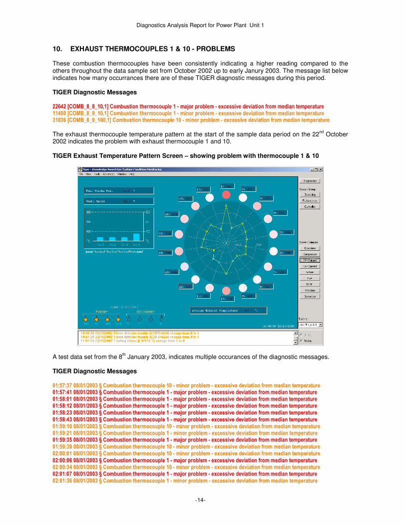
10. EXHAUST THERMOCOUPLES 1 & 10 - PROBLEMS These combustion thermocouples have been consistently indicating a higher reading compared to the others throughout the data sample set from October 2002 up to early Janury 2003. The message list below indicates how many occurrances there are of these TIGER diagnostic messages during this period. TIGER Diagnostic Messages 22642 [COMB_8_8_10,1] Combustion thermocouple 1 - major problem - excessive deviation from median temperature 11450 [COMB_8_9_10,1] Combustion thermocouple 1 - minor problem - excessive deviation from median temperature 31836 [COMB_8_9_100,1] Combustion thermocouple 10 - minor problem - excessive deviation from median temperature
The exhaust thermocouple temperature pattern at the start of the sample data period on the 22
nd October
2002 indicates the problem with exhaust thermocouple 1 and 10. TIGER Exhaust Temperature Pattern Screen – showing problem with thermocouple 1 & 10
A test data set from the 8
th January 2003, indicates multiple occurances of the diagnostic messages.
TIGER Diagnostic Messages 01:57:37 08/01/2003 § Combustion thermocouple 10 - minor problem - excessive deviation from median temperature 01:57:41 08/01/2003 § Combustion thermocouple 1 - major problem - excessive deviation from median temperature 01:58:01 08/01/2003 § Combustion thermocouple 1 - major problem - excessive deviation from median temperature 01:58:12 08/01/2003 § Combustion thermocouple 1 - major problem - excessive deviation from median temperature 01:58:23 08/01/2003 § Combustion thermocouple 1 - major problem - excessive deviation from median temperature 01:58:43 08/01/2003 § Combustion thermocouple 1 - major problem - excessive deviation from median temperature 01:59:10 08/01/2003 § Combustion thermocouple 10 - minor problem - excessive deviation from median temperature 01:59:21 08/01/2003 § Combustion thermocouple 1 - minor problem - excessive deviation from median temperature 01:59:35 08/01/2003 § Combustion thermocouple 1 - major problem - excessive deviation from median temperature 01:59:39 08/01/2003 § Combustion thermocouple 10 - minor problem - excessive deviation from median temperature 02:00:01 08/01/2003 § Combustion thermocouple 10 - minor problem - excessive deviation from median temperature 02:00:06 08/01/2003 § Combustion thermocouple 1 - major problem - excessive deviation from median temperature 02:00:34 08/01/2003 § Combustion thermocouple 10 - minor problem - excessive deviation from median temperature 02:01:07 08/01/2003 § Combustion thermocouple 1 - major problem - excessive deviation from median temperature 02:01:36 08/01/2003 § Combustion thermocouple 1 - minor problem - excessive deviation from median temperature

Diagnostics Analysis Report for Power Plant Unit 1
-15-
02:01:36 08/01/2003 § Combustion thermocouple 10 - minor problem - excessive deviation from median temperature 02:01:50 08/01/2003 § Combustion thermocouple 1 - major problem - excessive deviation from median temperature 02:01:59 08/01/2003 § Combustion thermocouple 1 - major problem - excessive deviation from median temperature 02:03:49 08/01/2003 § Combustion thermocouple 1 - minor problem - excessive deviation from median temperature 02:03:58 08/01/2003 § Combustion thermocouple 10 - minor problem - excessive deviation from median temperature 02:04:52 08/01/2003 § Combustion thermocouple 1 - minor problem - excessive deviation from median temperature 02:05:00 08/01/2003 § Combustion thermocouple 1 - minor problem - excessive deviation from median temperature 02:05:00 08/01/2003 § Combustion thermocouple 10 - minor problem - excessive deviation from median temperature 02:05:09 08/01/2003 § Combustion thermocouple 1 - minor problem - excessive deviation from median temperature 02:05:21 08/01/2003 § Combustion thermocouple 1 - minor problem - excessive deviation from median temperature 02:05:23 08/01/2003 § Combustion thermocouple 1 - minor problem - excessive deviation from median temperature 02:05:31 08/01/2003 § Combustion thermocouple 1 - minor problem - excessive deviation from median temperature 02:13:00 08/01/2003 § Combustion thermocouple 1 - major problem - excessive deviation from median temperature occured 25 times in time interval 01:57:41 08/01/2003 to 02:12:31 08/01/2003 02:13:00 08/01/2003 § Combustion thermocouple 10 - minor problem - excessive deviation from median temperature occured 28 times in time interval 01:57:33 08/01/2003 to 02:13:00 08/01/2003 02:13:00 08/01/2003 § Combustion thermocouple 1 - minor problem - excessive deviation from median temperature occured 25 times in time interval 01:57:33 08/01/2003 to 02:12:50 08/01/2003
The data graphs of the thermocouples for this period also illustrate the probems. Adjacent exhaust thermocouples 18, 1,2 and average exhaust temperature.
Adjacent exhaust thermocouples 9, 10, 11 and average exhaust temperature.

Diagnostics Analysis Report for Power Plant Unit 1
-16-
The exhaust thermocouple temperature pattern on 8th January 2003 indicates a similar problem with
thermocouples 1 and 10 to that in October 2002. TIGER Exhaust Temperature Pattern Screen – showing problem with thermocouple 1 & 10
Analysis This could indicate a thermocouple or combustion problem. As indicated by the TIGER diagnostics this is most likely to be a thermocouple problem, as the adjacent thermocouples are reading normally. The problem appears to have stayed fairly constant during this time, which may also indicate it as more likely to be a problem with the thermocouples rather than combustion related. The large number of messages generated reflects the fact that the problem is near the bottom end of the range of severity, as TIGER detects the problem as it increases past the diagnostic limits on successive occasions. The problem on thermocouple 10 is listed as minor by TIGER as it is less severe, and the problem with thermocouple 1 is also listed as minor as during some periods when the problem becomes less severe and is then categorised as minor rather than major by TIGER diagnostics. The example data set for the 8
th January
indicates this. If the problem is due to combustion problems, this could be caused by: � Mismatch in fuel nozzles – these should be flow checked after fitting. Should be within +- 5%. � Dirty compressor and/or combustion components – an offline or online wash can help sort both. This
can be caused by dust fouling compressor and turbine stages, and in some cases dirt from combustion, particularly if liquid fuel is used.
� Seals faults on combustion cans or transition pieces Recommendation At this stage this a minor problem. However, when convenient the thermocouples and the thermocouple wiring should be checked for faults, and if found not to be faulty, the combustors that relate to these thermocouples (this can be determined from the swirl pattern) should then be checked also.

Diagnostics Analysis Report for Power Plant Unit 1
-17-
11. EXHAUST TEMPERATURE SPREAD - ADJACENT TC'S
TIGER detects frequent occurrences of alarms L60SP5 (Exhaust temperature spread - adjacent TC'S) & L60SP6 (Exhaust temperature spread - adjacent TC'S). However, it is not clear what is generating these. They occur even though the exhaust temperature spread is low. An example of this occurs at 17:30 on 02/12/2002. Exhaust temperatures
Exhaust temperature spreads and limit
TIGER exhaust temperature pattern screen – showing spread is ok

Diagnostics Analysis Report for Power Plant Unit 1
-18-
Analysis In this example data set, the turbine is running at part load, and there is some instability in the exhaust temperatures, presumably due to gas supply pressure fluctuations. No major transients occur in the exhaust temperature spreads during this time. Also, although the spreads do increase somewhat towards the later part of the data sequence as turbine power is increased, the spreads are quite low throughout. These signals normally indicate exhaust temperature spread problems. However site has informed us that the signals are not working at present. This is confirmed by this example data sequence, where they appear to be spurious alarms. This may indicate an incorrect alarm setting in the Mk V, i.e., an alarm tolerance set too low. Recommendation These are false alarms from the controller. We have latched these messages in TIGER, so they can be ignored.

Diagnostics Analysis Report for Power Plant Unit 1
-19-
12. LUBE OIL TEMPERATURE PROBLEMS This daily trend graph indicates how lube oil temperatures increases with ambient temperatures, and rises above the alarm limit. Lube oil header and ambient temperature, lube oil high temperature alarm.
Turbine power and speed.
The trend graph for five days in November indicates how lube oil temperatures vary with ambient temperatures, and rise above the alarm limit, causing alarms The turbine is running throughout this period. Lube oil header and ambient temperature, lube oil high temperature alarm.

Diagnostics Analysis Report for Power Plant Unit 1
-20-
The monthly trend graph for November indicates how lube oil temperatures vary with ambient temperatures during the month, generally declining. Speed is included to indicate when the turbine is running or stopped. Lube oil header and ambient temperature, and speed.
TIGER Diagnostic Messages 08:50:45 30/10/2002 § Lube temperature turbine header, GT/GG [LTTH1] too high. Limit 58.00 degC occured 557 times in time interval 08:50:45 30/10/2002 to 10:37:03 30/10/2002 11:01:28 30/10/2002 § Lube oil temperature alarm [L30LOA] change from 0 to 1 occured 37 times in time interval 11:01:28 30/10/2002 to 11:16:26 30/10/2002
Analysis The problem with the lube oil header temperature was first indicated by TIGER warning messages on the 21
st October, and this problem also causes controller alarms to occur, as the temperature rises. On the 30
th
October, as shown above, first TIGER generates warning messages as the temperature rises above the TIGER limit of 58 Deg C with the ambient temperature increase, and then controller alarms occur. The controller alarm clears when the turbine is shutdown. These high temperatures could also be related to the high vibration levels on the generator. There is also the possibility that this thermocouple is not reading accurately. The controller alarm (L30LOA) has not occurred since 22
nd November 2002. Examination of the monthly
trend graph for November (shown above) indicates that this is probably to the falling ambient temperatures during the month. This a significant problem. Lube oil temps should be in the range 54 – 70 Deg C (lube oil header temperature), but they are higher than this and vary with ambient temperatures rather than staying constant. If turbine is too hot, this can cause problems with the bearings including problems with misalignment, particularly at the generator end of the turbine, where the support legs can get too hot and distort. The high lube temperatures may be caused by cooling system problems. This could be caused by clogging of radiators (i.e. sand) or cooling fan problems. There is also a low water cooling level alarm present. It could also be caused by water leakage at the three way water control valve. Alternatively a manual lock may have been applied to the valve so it is not controlling water flow as ambient temperatures change. Or, temperature control of the cooling system is not working for some other reason. Recommendation Check the lube oil system and lube oil water cooling system, as a further increases in lube temperatures could lead to a trip, and possibly extra wear on the turbine. Check the water cooling system for:
� clogging of radiators (i.e. sand) � cooling fan problems � cooling water reservoir level � water leakage at the three way water control valve � possible manual lock on the control valve � malfunction of the temperature control of the cooling water system

Diagnostics Analysis Report for Power Plant Unit 1
-21-
13. CONTROLLER T VOTING STATUS ALARM Analysis This alarm (L3VOTE-T) has continued to occur regularly. The alarm should be monitored, as an increase in frequency of occurrence may indicate controller problems. Could be due to bad connections in the controller or cables, or dust inside the controller. Recommendation Check relevant controller cards and connections and clean the controller boards and housing with compressed air.
Diagnostics Analysis Report for Power Plant Unit 1
-22-
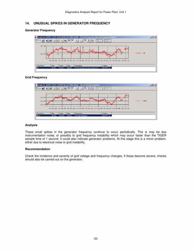
14. UNUSUAL SPIKES IN GENERATOR FREQUENCY Generator Frequency
Grid Frequency
Analysis These small spikes in the generator frequency continue to occur periodically. This is may be due instrumentation noise, or possibly to grid frequency instability which may occur faster than the TIGER sample time of 1 second. It could also indicate generator problems. At this stage this is a minor problem, either due to electrical noise or grid instability. Recommendation Check the incidence and severity of grid voltage and frequency changes. If these become severe, checks should also be carried out on the generator.
Diagnostics Analysis Report for Power Plant Unit 1
-23-
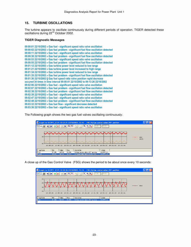
15. TURBINE OSCILLATIONS The turbine appears to oscillate continuously during different periods of operation. TIGER detected these oscillations during 22
nd October 2002.
TIGER Diagnostic Messages 09:00:01 22/10/2002 » Gas fuel - significant speed ratio valve oscillation 09:00:02 22/10/2002 » Gas fuel problem - significant fuel flow oscillation detected 09:00:11 22/10/2002 » Gas fuel - significant speed ratio valve oscillation 09:00:38 22/10/2002 » Gas fuel problem - significant fuel flow oscillation detected 09:00:53 22/10/2002 » Gas fuel - significant speed ratio valve oscillation 09:00:55 22/10/2002 » Gas fuel problem - significant fuel flow oscillation detected 09:01:12 22/10/2002 » Gas turbine power level reduced to low range 09:01:21 22/10/2002 » Gas turbine power level increased to high range 09:01:34 22/10/2002 » Gas turbine power level reduced to low range 09:01:35 22/10/2002 » Gas fuel problem - significant fuel flow oscillation detected 09:01:36 22/10/2002 § Gas fuel speed ratio valve position rapid decrease occured 34 times in time interval 09:00:01 22/10/2002 to 09:13:26 22/10/2002 09:02:06 22/10/2002 » Gas fuel - significant speed ratio valve oscillation 09:02:07 22/10/2002 » Gas fuel problem - significant fuel flow oscillation detected 09:02:38 22/10/2002 » Gas fuel problem - significant fuel flow oscillation detected 09:02:38 22/10/2002 » Gas fuel - significant speed ratio valve oscillation 09:02:47 22/10/2002 » Gas fuel - significant speed ratio valve oscillation 09:02:48 22/10/2002 » Gas fuel problem - significant fuel flow oscillation detected 09:03:32 22/10/2002 » Gas fuel flow - significant decrease detected 09:03:36 22/10/2002 » Gas fuel - significant speed ratio valve oscillation
The Following graph shows the two gas fuel valves oscillating continuously:
A close up of the Gas Control Valve (FSG) shows the period to be about once every 10 seconds:

Diagnostics Analysis Report for Power Plant Unit 1
-24-
The Speed Ratio Valve (FSGR) is following the FSG Valve as seen in this zoomed image:
This causes oscillations in the P2 Pressure:
And the fuel flow:
Most importantly, this leads to a constant oscillation of the power output in Megawatts:

Diagnostics Analysis Report for Power Plant Unit 1
-25-
The graph of the medium exhaust gas temperature shows the oscillation in temperature.
TIGER’s calculated mean exhaust temperature also shows this well:
Another example of these turbine oscillations was detected by TIGER during 2
nd December 2002.
TIGER Diagnostic Messages 06:00:10 02/12/2002 » Gas fuel - significant speed ratio valve oscillation 06:00:11 02/12/2002 » Gas fuel problem - significant fuel flow oscillation detected 06:00:20 02/12/2002 » Gas fuel - significant speed ratio valve oscillation 06:00:26 02/12/2002 » Gas fuel problem - significant fuel flow oscillation detected 06:00:30 02/12/2002 » Gas fuel - significant speed ratio valve oscillation 06:00:40 02/12/2002 » Gas fuel - significant speed ratio valve oscillation 06:00:41 02/12/2002 » Gas fuel problem - significant fuel flow oscillation detected 06:00:50 02/12/2002 » Gas fuel - significant speed ratio valve oscillation 06:00:51 02/12/2002 » Gas fuel problem - significant fuel flow oscillation detected 06:01:00 02/12/2002 » Gas fuel - significant speed ratio valve oscillation 06:01:01 02/12/2002 » Gas fuel problem - significant fuel flow oscillation detected 06:01:10 02/12/2002 » Gas fuel - significant speed ratio valve oscillation 06:01:11 02/12/2002 » Gas fuel problem - significant fuel flow oscillation detected 06:01:20 02/12/2002 » Gas fuel - significant speed ratio valve oscillation 06:01:21 02/12/2002 » Gas fuel problem - significant fuel flow oscillation detected 06:01:30 02/12/2002 » Gas fuel problem - significant fuel flow oscillation detected 06:01:30 02/12/2002 » Gas fuel - significant speed ratio valve oscillation
An example of this occurs at 06:00 on 02/12/2002, and is shown graphically below.

Diagnostics Analysis Report for Power Plant Unit 1
-26-
Fuel Control Valve Oscillations
Fuel Speed Ratio Valve Oscillations
Exhaust Temperature Oscillations
Power Oscillations

Diagnostics Analysis Report for Power Plant Unit 1
-27-
Grid Voltage Instability
Analysis Although these oscillations are relatively small, they are abnormal. The thermal cycling caused by the oscillations will cause increased wear and tear to the hot gas path and other components and reduce component life. These oscillations will also reduce turbine performance. It is possible that these turbine oscillations may be caused by grid voltage oscillations. However, as can be seen from the graphs above, the correlation is not very high, so it is more likely to be caused by another internal problem, such as fuel control or gas fuel pressure problems. These oscillations are a significant problem, and are most likely due to fuel control problems. This could be due to controller tuning, hydraulics problems or gas fuel valve component wear. Worn valves are often the cause of this, and even if they are still within the manufacturers tolerance limits, worn valves can cause this type of poor fuel control to occur. Recommendation When convenient, try auto tuning the controller and fuel valve system. If this fails, a manual controller and fuel valve tuning could be tried. If this fails, then check the operation of the gas fuel system and the pressure stability of the gas fuel supply. Overhaul and/or replace any worn or faulty fuel valve components as required.
Diagnostics Analysis Report for Power Plant Unit 1
-28-
16. ALARMS DUE TO CONTROLLER MAINTENANCE A series of alarms occurred indicating controller problems. TIGER Diagnostic Messages 08:52:59 27/11/2002 » Controller trip signal to protective module 08:52:59 27/11/2002 » Trip relay 1 08:52:59 27/11/2002 » Trip relay 2 08:54:13 27/11/2002 » Turbine trip detected 08:54:13 27/11/2002 » Compressor discharge temperature sensor 1 fault 08:54:13 27/11/2002 » Controller fault - Cable W74 Failed 08:54:13 27/11/2002 » Controller fault - Cable W73 Failed 08:54:13 27/11/2002 » Controller fault - Processor R Failed 08:54:13 27/11/2002 » Controller fault - Processor S Failed 08:54:13 27/11/2002 » Controller fault - Processor T Failed 08:54:23 27/11/2002 » Controller trip signal to protective module 08:54:23 27/11/2002 § T.d. loss of master protective [L4Y] change from 0 to 1 08:54:23 27/11/2002 » Generator breaker trip 08:54:23 27/11/2002 » Gas fuel hydraulic trip pressure low
Analysis This occurred when the turbine was stopped. The likely cause of these alarms was maintenance actions being carried out on the turbine controller, and if this is the case they can be ignored. Recommendation Check the maintenance log for the controller, to determine if these faults were false alarms due to maintenance activities. Note, the controller should be powered off before any maintenance is carried out on it.

Diagnostics Analysis Report for Power Plant Unit 1
-29-
17. ALARMS DUE TO R, S & T PROCESSOR DROP-OUTS TIGER diagnostics has detected controller processor drop outs fairly frequently. This has continued throughout the sample data set into January 2003 and has occurred mainly when the turbine was running. TIGER Diagnostic Messages 22:25:10 02/12/2002 » Controller S Processor dropout 22:25:10 02/12/2002 » Controller T Processor dropout
In this example, the drop out of the processors is indicated by the three seperate exhaust thermocouple groupings losing signal and dropping to –18 Deg C, which indicates signal loss. This is shown graphically below. Drop out of exhaust thermcouples due to s&t processor drop-out
Tiger exhaust temperature pattern screen – shows thermocouple drop outs

Diagnostics Analysis Report for Power Plant Unit 1
-30-
Note: This problem has occurred many times i.e. during December 2002.: TIGER Diagnostic Messages 23 Controller R Processor dropout 112 Controller S Processor dropout 1149 Controller T Processor dropout
Analysis TIGER diagnostics has detected drop outs of the R,S & T turbine controller processors by detecting the signal loss values of the three interleaved sets of exhaust thermocouples. These drop outs could be due to bad connections within the controller. This may indicate that the controller is becoming more unreliable. There were over 1000 of these incidents recorded during 1
st two weeks of January 2003. This is a serious
problem as this could cause a turbine trip, or prevent a startup. The drop-outs could be caused by bad connections in the controller or cables, or faults in the controller electronics. Recommendation Check the relevant controller cards and connections and clean the controller boards and housing with compressed air. If necessary, replace any faulty controller processor components.
Diagnostics Analysis Report for Power Plant Unit 1
-31-
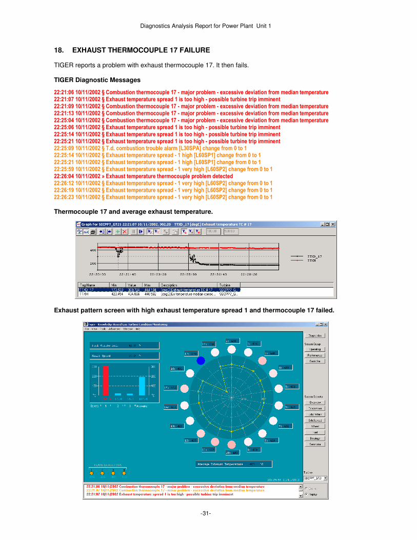
18. EXHAUST THERMOCOUPLE 17 FAILURE TIGER reports a problem with exhaust thermocouple 17. It then fails. TIGER Diagnostic Messages
22:21:06 10/11/2002 § Combustion thermocouple 17 - major problem - excessive deviation from median temperature 22:21:07 10/11/2002 § Exhaust temperature spread 1 is too high - possible turbine trip imminent 22:21:09 10/11/2002 § Combustion thermocouple 17 - major problem - excessive deviation from median temperature 22:21:13 10/11/2002 § Combustion thermocouple 17 - major problem - excessive deviation from median temperature 22:25:04 10/11/2002 § Combustion thermocouple 17 - major problem - excessive deviation from median temperature 22:25:06 10/11/2002 § Exhaust temperature spread 1 is too high - possible turbine trip imminent 22:25:14 10/11/2002 § Exhaust temperature spread 1 is too high - possible turbine trip imminent 22:25:21 10/11/2002 § Exhaust temperature spread 1 is too high - possible turbine trip imminent 22:25:09 10/11/2002 § T.d. combustion trouble alarm [L30SPA] change from 0 to 1 22:25:14 10/11/2002 § Exhaust temperature spread - 1 high [L60SP1] change from 0 to 1 22:25:21 10/11/2002 § Exhaust temperature spread - 1 high [L60SP1] change from 0 to 1 22:25:59 10/11/2002 § Exhaust temperature spread - 1 very high [L60SP2] change from 0 to 1 22:26:04 10/11/2002 » Exhaust temperature thermocouple problem detected 22:26:12 10/11/2002 § Exhaust temperature spread - 1 very high [L60SP2] change from 0 to 1 22:26:19 10/11/2002 § Exhaust temperature spread - 1 very high [L60SP2] change from 0 to 1 22:26:23 10/11/2002 § Exhaust temperature spread - 1 very high [L60SP2] change from 0 to 1
Thermocouple 17 and average exhaust temperature.
Exhaust pattern screen with high exhaust temperature spread 1 and thermocouple 17 failed.

Diagnostics Analysis Report for Power Plant Unit 1
-32-
Analysis Thermocouple 17 starts failing at around 22:21:06. This causes the high spread value. It finally fails completely about five minutes later at around 22:25:09. This could be caused by a short circuit in the thermocouple, giving a spurious low reading. There could also be a short circuit in the termination box or in the wiring connections to the controller. Recommendation Check the wiring and thermocouple. Check for a short circuit in the thermocouple or in the termination box or in the wiring connections to the controller. Repair or replace as necessary.

Diagnostics Analysis Report for Power Plant Unit 1
-33-
19. EXHAUST TEMPERATURE SPREAD TRIP The gas turbine is running in a stable state at about 65 Mw, and then trips on exhaust over temperature. TIGER Exhaust Temperature Pattern Screen - just prior to trip
Exhaust Temperature Spreads and Limit
Exhaust Temperatures

Diagnostics Analysis Report for Power Plant Unit 1
-34-
Exhaust Temperature and Power
Gas Fuel P2 Pressure
TIGER Diagnostic Messages
17:00:00 12/11/2002 § Combustion thermocouple 17 - major problem - excessive deviation from median temperature 17:00:00 12/11/2002 § Exhaust temperature spread 1 is too high - possible turbine trip imminent 17:01:22 12/11/2002 » Gas fuel - significant speed ratio valve oscillation 17:01:24 12/11/2002 » Gas fuel problem - significant fuel flow oscillation detected 17:01:34 12/11/2002 » Gas fuel - significant speed ratio valve oscillation 17:01:39 12/11/2002 » Gas fuel problem - significant fuel flow oscillation detected 17:01:44 12/11/2002 § Gas fuel flow significant increase occured 46 times in time interval 17:00:02 12/11/2002 to 17:07:42 12/11/2002 17:01:49 12/11/2002 » Gas fuel flow - significant decrease detected 17:02:47 12/11/2002 § Combustion thermocouple 15 - major problem - excessive deviation from median temperature 17:02:47 12/11/2002 § Exhaust temperature spread 2 is too high - possible turbine trip imminent 17:05:50 12/11/2002 § Combustion thermocouple 1 - major problem - excessive deviation from median temperature 17:07:36 12/11/2002 » Exhaust temperature - major problems - excessive deviation of thermocouples from median temperature 17:07:39 12/11/2002 § Exhaust temperature spread 3 is too high - possible turbine trip imminent 17:07:42 12/11/2002 » Exhaust temperature - rapid increase 17:07:44 12/11/2002 § Gas turbine is not running in high load operating range 17:07:44 12/11/2002 § Gas turbine is not running in high load range using gas fuel 17:07:45 12/11/2002 § Gas turbine trip 17:07:45 12/11/2002 » Turbine trip due excessive exhaust temperature spread
Analysis
Initially exhaust thermocouple 17 is reading low and there is a high spread. Eventually, 15 and 16 also become low, and this causes the trip. As there is no change in power levels, this is probably due to a thermocouple problem. However, three thermocouples reading low simultaneously is normally indicative of combustion problems. During this time, there is significant instability in the gas fuel control valves, with all major parameters such as power, exhaust temperature and P2 pressure oscillating. It is possible that these problems could also be linked to the cause of the trip, although it is more likely that that the problem is related to the incidents on the 10
th and 13
th of November where thermocouple 17 was reading cold and
also failed (on the 10th). This could be caused by a short circuit in the thermocouples, giving a spurious low
reading. There could also be a short circuits in the termination box or in the wiring connections to the controller.

Diagnostics Analysis Report for Power Plant Unit 1
-35-
Recommendation Check the wiring and thermocouple. Check for a short circuit in the thermocouple or in the termination box or in the wiring connections to the controller. Repair or replace as necessary.
Diagnostics Analysis Report for Power Plant Unit 1
-36-
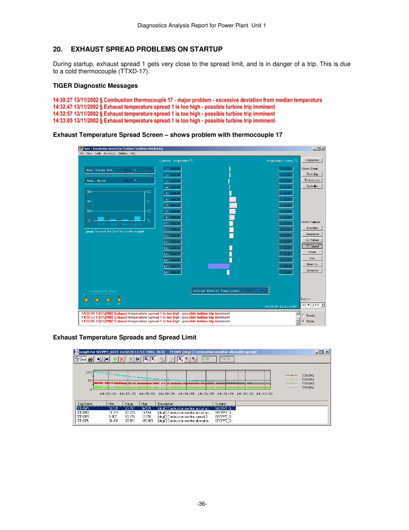
20. EXHAUST SPREAD PROBLEMS ON STARTUP During startup, exhaust spread 1 gets very close to the spread limit, and is in danger of a trip. This is due to a cold thermocouple (TTXD-17). TIGER Diagnostic Messages 14:30:27 13/11/2002 § Combustion thermocouple 17 - major problem - excessive deviation from median temperature 14:32:47 13/11/2002 § Exhaust temperature spread 1 is too high - possible turbine trip imminent 14:32:57 13/11/2002 § Exhaust temperature spread 1 is too high - possible turbine trip imminent 14:33:05 13/11/2002 § Exhaust temperature spread 1 is too high - possible turbine trip imminent
Exhaust Temperature Spread Screen – shows problem with thermocouple 17
Exhaust Temperature Spreads and Spread Limit

Diagnostics Analysis Report for Power Plant Unit 1
-37-
Exhaust Temperatures
There have been spread 1 problems occuring quite frequently, up to this time, most likely due to the low readings on thermocouple 17. TIGER Diagnostic Messages 10:04:22 28/10/2002 [COMB_9_7_10,1] Exhaust temperature spread 1 is too high - possible turbine trip imminent 10:16:53 28/10/2002 [COMB_9_7_10,1] Exhaust temperature spread 1 is too high - possible turbine trip imminent 10:29:28 28/10/2002 [COMB_9_7_10,1] Exhaust temperature spread 1 is too high - possible turbine trip imminent 04:32:09 29/10/2002 [COMB_9_7_10,1] Exhaust temperature spread 1 is too high - possible turbine trip imminent 11:59:59 29/10/2002 [COMB_9_7_10,1] Exhaust temperature spread 1 is too high - possible turbine trip imminent 23:59:59 29/10/2002 [COMB_9_7_10,1] Exhaust temperature spread 1 is too high - possible turbine trip imminent 10:45:48 03/11/2002 [COMB_9_7_10,1] Exhaust temperature spread 1 is too high - possible turbine trip imminent 22:21:07 10/11/2002 [COMB_9_7_10,1] Exhaust temperature spread 1 is too high - possible turbine trip imminent 22:25:06 10/11/2002 [COMB_9_7_10,1] Exhaust temperature spread 1 is too high - possible turbine trip imminent 22:25:14 10/11/2002 [COMB_9_7_10,1] Exhaust temperature spread 1 is too high - possible turbine trip imminent 22:25:21 10/11/2002 [COMB_9_7_10,1] Exhaust temperature spread 1 is too high - possible turbine trip imminent 10:52:16 11/11/2002 [COMB_9_7_10,1] Exhaust temperature spread 1 is too high - possible turbine trip imminent 13:32:54 11/11/2002 [COMB_9_7_10,1] Exhaust temperature spread 1 is too high - possible turbine trip imminent 16:46:26 11/11/2002 [COMB_9_7_10,1] Exhaust temperature spread 1 is too high - possible turbine trip imminent 05:00:45 12/11/2002 [COMB_9_7_10,1] Exhaust temperature spread 1 is too high - possible turbine trip imminent
Analysis This could have been due to a bad thermocouple or combustion problem. This incident was probably related to the previous one on the 10
th November where thermocouple 17 failed, so as indicated by TIGER
diagnostics it appeared to be due to a thermocouple problem. This could be caused by a short circuit in the thermocouple, giving a spurious low reading. There could also be a short circuit in the termination box or in the wiring connections to the controller. Recommendation Check the wiring and thermocouple. Check for a short circuit in the thermocouple or in the termination box or in the wiring connections to the controller. Repair or replace as necessary.
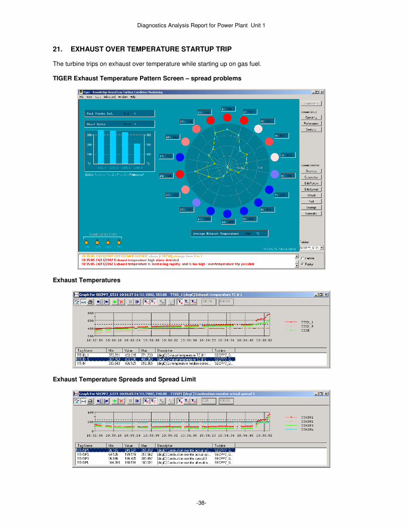
Diagnostics Analysis Report for Power Plant Unit 1
-38-
21. EXHAUST OVER TEMPERATURE STARTUP TRIP The turbine trips on exhaust over temperature while starting up on gas fuel. TIGER Exhaust Temperature Pattern Screen – spread problems
Exhaust Temperatures
Exhaust Temperature Spreads and Spread Limit
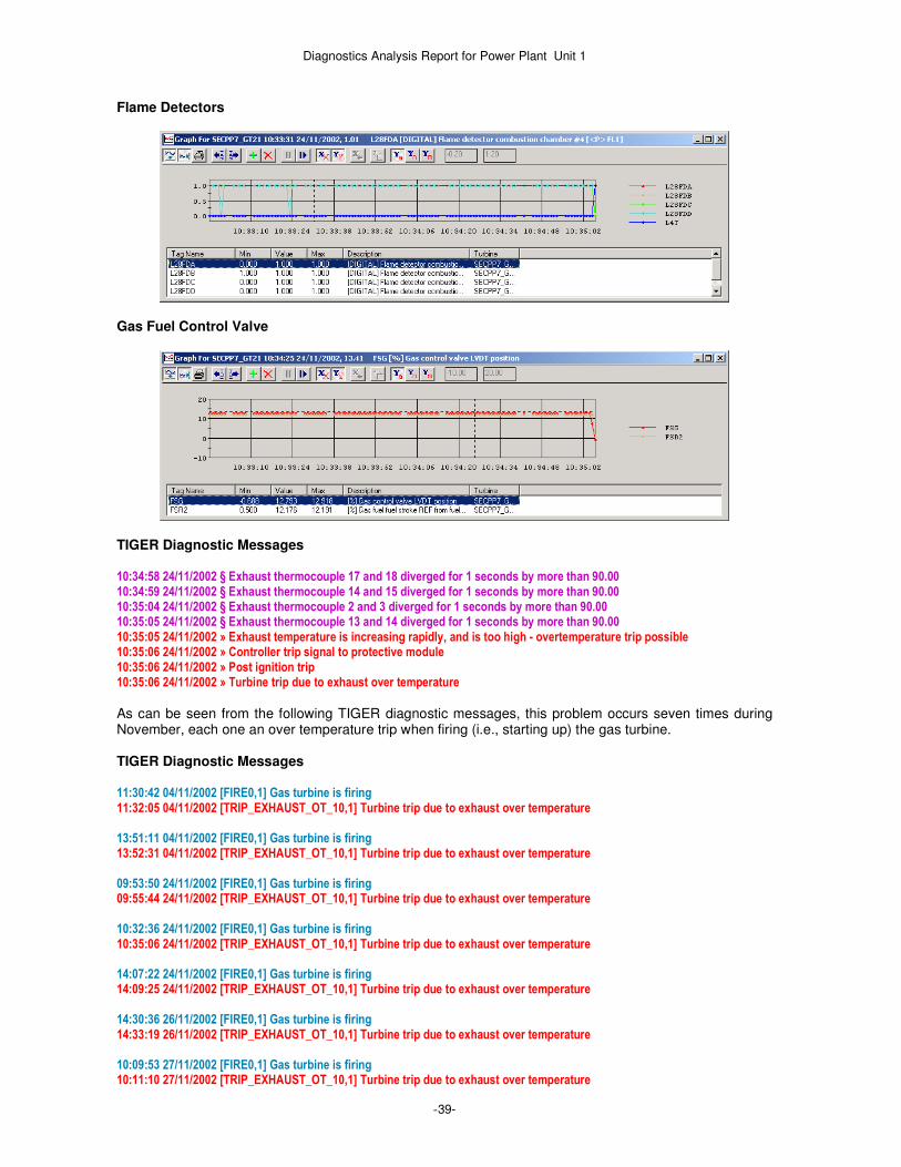
Diagnostics Analysis Report for Power Plant Unit 1
-39-
Flame Detectors
Gas Fuel Control Valve
TIGER Diagnostic Messages 10:34:58 24/11/2002 § Exhaust thermocouple 17 and 18 diverged for 1 seconds by more than 90.00 10:34:59 24/11/2002 § Exhaust thermocouple 14 and 15 diverged for 1 seconds by more than 90.00 10:35:04 24/11/2002 § Exhaust thermocouple 2 and 3 diverged for 1 seconds by more than 90.00 10:35:05 24/11/2002 § Exhaust thermocouple 13 and 14 diverged for 1 seconds by more than 90.00 10:35:05 24/11/2002 » Exhaust temperature is increasing rapidly, and is too high - overtemperature trip possible 10:35:06 24/11/2002 » Controller trip signal to protective module 10:35:06 24/11/2002 » Post ignition trip 10:35:06 24/11/2002 » Turbine trip due to exhaust over temperature
As can be seen from the following TIGER diagnostic messages, this problem occurs seven times during November, each one an over temperature trip when firing (i.e., starting up) the gas turbine. TIGER Diagnostic Messages 11:30:42 04/11/2002 [FIRE0,1] Gas turbine is firing 11:32:05 04/11/2002 [TRIP_EXHAUST_OT_10,1] Turbine trip due to exhaust over temperature 13:51:11 04/11/2002 [FIRE0,1] Gas turbine is firing 13:52:31 04/11/2002 [TRIP_EXHAUST_OT_10,1] Turbine trip due to exhaust over temperature 09:53:50 24/11/2002 [FIRE0,1] Gas turbine is firing 09:55:44 24/11/2002 [TRIP_EXHAUST_OT_10,1] Turbine trip due to exhaust over temperature 10:32:36 24/11/2002 [FIRE0,1] Gas turbine is firing 10:35:06 24/11/2002 [TRIP_EXHAUST_OT_10,1] Turbine trip due to exhaust over temperature 14:07:22 24/11/2002 [FIRE0,1] Gas turbine is firing 14:09:25 24/11/2002 [TRIP_EXHAUST_OT_10,1] Turbine trip due to exhaust over temperature 14:30:36 26/11/2002 [FIRE0,1] Gas turbine is firing 14:33:19 26/11/2002 [TRIP_EXHAUST_OT_10,1] Turbine trip due to exhaust over temperature 10:09:53 27/11/2002 [FIRE0,1] Gas turbine is firing 10:11:10 27/11/2002 [TRIP_EXHAUST_OT_10,1] Turbine trip due to exhaust over temperature

Diagnostics Analysis Report for Power Plant Unit 1
-40-
Analysis TIGER detects over temperature problems, and the Turbine trips on over temperature. TIGER also indicates spread problems, which also become very severe. There are also indications of poor flame or loss of flame on some combustors, as one flame detector is either low or has transient drop outs. This would confirm that combustion is poorly established or unstable on one or more combustors, causing the bad spread. All this indicates a serious combustion problem occurred. It appears that the turbine is not cross–firing at some points, and this indicates one or more igniters could be faulty. There was very uneven combustion followed by delayed flame out after the gas fuel was shutdown. This is a very serious problem, and could be caused by liquid distillate fuel being present in the gas fuel during startup. Possible causes are:
� Poor gas quality. � Failure of gas scrubbers (if any are being used). � Gas fuel not being heated to the correct temperature (check gas fuel heaters). � Build up over time of distillates in the gas fuel lines. � Faulty fuel nozzles. � Faulty combustion cans or transition pieces.
A temperature of greater than 600 Degrees C in the exhaust (in this case 900 Deg C was seen) probably indicates a fire in the exhaust plenum, due to distillate fuel being forced through the turbine stage and then falling down into the plenum and igniting. It is possible that the turbine may have been damaged by these 7 repeated bad startups detected by TIGER diagnostics. Recommendation Check that all igniters are functioning correctly. Fire on liquid and then do a partial transfer to gas, running on mixed fuel with around 10-20% gas and 80-90% liquid. This should then ensure any spurious distillates in the gas fuel get burnt of in a harmless and controlled manner. If the problem persists, check for faults in the fuel nozzles, or failed seals in the combustion cans and/or transition pieces.
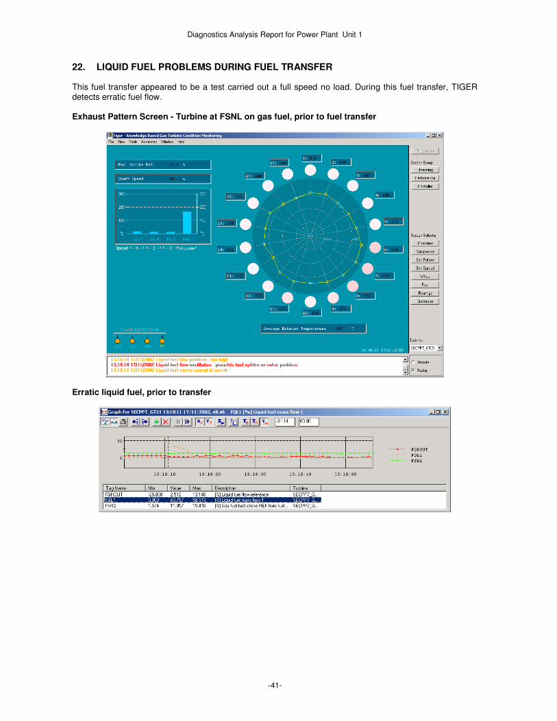
Diagnostics Analysis Report for Power Plant Unit 1
-41-
22. LIQUID FUEL PROBLEMS DURING FUEL TRANSFER This fuel transfer appeared to be a test carried out a full speed no load. During this fuel transfer, TIGER detects erratic fuel flow. Exhaust Pattern Screen - Turbine at FSNL on gas fuel, prior to fuel transfer
Erratic liquid fuel, prior to transfer

Diagnostics Analysis Report for Power Plant Unit 1
-42-
Exhaust Pattern Screen - Turbine at FSNL on liquid fuel, during fuel transfer
Fuel setpoints during fuel transfer.
Erratic flame detector 2 during fuel transfers.

Diagnostics Analysis Report for Power Plant Unit 1
-43-
TIGER Diagnostic Messages 13:18:10 17/11/2002 » Liquid fuel flow oscillation - possible fuel splitter or valve problem 13:18:17 17/11/2002 » Liquid fuel flow problem - too low 13:18:19 17/11/2002 » Liquid fuel flow unstable - possible fuel splitter or valve problem 13:18:25 17/11/2002 » Liquid fuel flow unstable - possible fuel splitter or valve problem 13:18:45 17/11/2002 » Liquid fuel flow unstable - possible fuel splitter or valve problem 13:18:51 17/11/2002 » Liquid fuel flow unstable - possible fuel splitter or valve problem 13:19:27 17/11/2002 § Flame detector 2 [FD-INTENS-2] too low. Limit 100.00 CNT15 13:20:11 17/11/2002 § Flame detector 1 and 2 different for 1 seconds by more than 0.00 13:20:11 17/11/2002 § Flame detector 2 and 3 different for 1 seconds by more than 0.00 13:20:26 17/11/2002 § Flame detector 1 and 2 different for 1 seconds by more than 0.00 13:20:26 17/11/2002 § Flame detector 2 and 3 different for 1 seconds by more than 0.00 13:22:00 17/11/2002 § Flame detector 2 [FD-INTENS-2] too low. Limit 100.00 CNT15 13:22:06 17/11/2002 § Flame detector 2 [FD-INTENS-2] too low. Limit 100.00 CNT15 13:22:40 17/11/2002 § Flame detector 2 [FD-INTENS-2] too low. Limit 100.00 CNT15 13:22:48 17/11/2002 § Flame detector 2 [FD-INTENS-2] too low. Limit 100.00 CNT15 13:23:01 17/11/2002 § Flame detector 1 and 2 different for 1 seconds by more than 0.00 13:23:01 17/11/2002 § Flame detector 2 and 3 different for 1 seconds by more than 0.00 13:23:06 17/11/2002 § Flame detector 1 and 2 different for 1 seconds by more than 0.00 13:23:06 17/11/2002 § Flame detector 2 and 3 different for 1 seconds by more than 0.00 13:23:10 17/11/2002 § Flame detector 1 and 2 different for 1 seconds by more than 0.00 13:23:10 17/11/2002 § Flame detector 2 and 3 different for 1 seconds by more than 0.00 13:23:13 17/11/2002 § Exhaust thermocouple 14 and 15 diverged for 1 seconds by more than 30.00 13:23:15 17/11/2002 § Flame detector 4 [FD-INTENS-4] too low. Limit 100.00 CNT15
Analysis There is a major spike in the flow, followed by smaller transients. These are not in response to fuel demand. This may indicate problems in the liquid fuel system. The subsequent fuel transfer is successful, however as can be seen from the spread screen, the combustion on liquid fuel is poor, with an increase in spreads and a flame out indicated on one can. Based on this, It is possible that a liquid fuel startup or prolonged liquid fuel operation would fail Recommendation Check and overhaul the liquid fuel system.

Diagnostics Analysis Report for Power Plant Unit 1
-44-
23. TRIP ON COMPRESSOR BLEED VALVE 2 TROUBLE A normal fired shutdown is initiated, the turbine then trips with a compressor bleed valve position trouble trip. TIGER Diagnostic Messages 15:15:30 13/11/2002 » Turbine trip - compressor bleed valve failed to open
Compressor Bleed Valves
Trip and Shutdown Signals
Turbine Speed
Analysis This is a minor problem, and occurs as one of the compressor bleed valves has too long delay in opening after the controller open command. This may indicate that the bleed valve is sticking. Recommendation The compressor bleed valves should be exercised to remove any unwanted stiction in the valves. The air operated pistons should be checked, and new seals fitted to these if required.
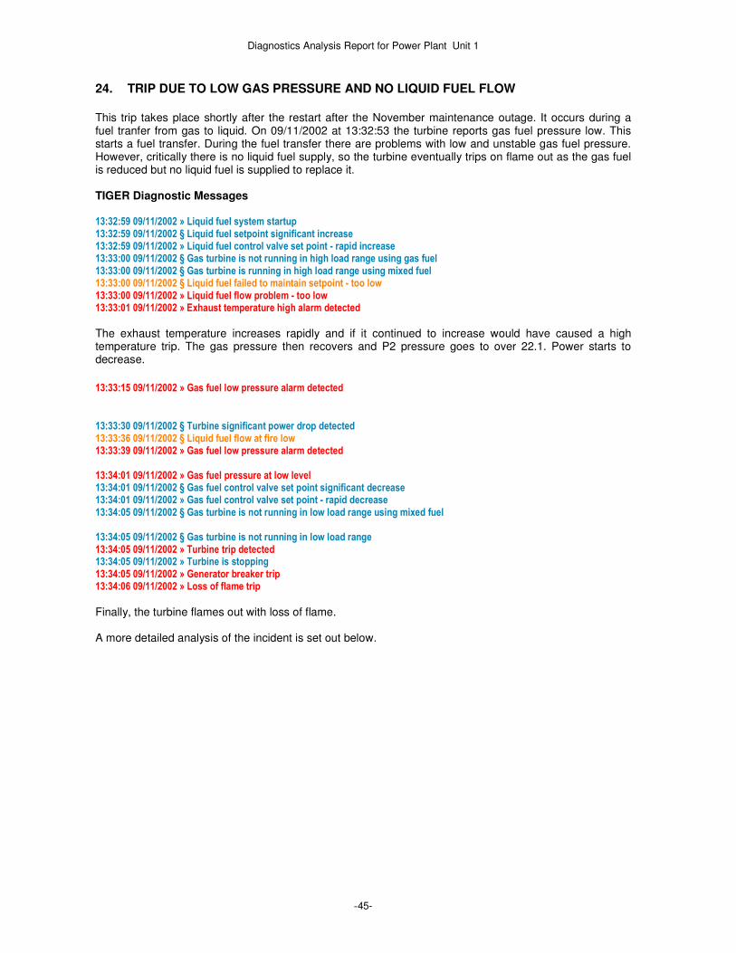
Diagnostics Analysis Report for Power Plant Unit 1
-45-
24. TRIP DUE TO LOW GAS PRESSURE AND NO LIQUID FUEL FLOW
This trip takes place shortly after the restart after the November maintenance outage. It occurs during a fuel tranfer from gas to liquid. On 09/11/2002 at 13:32:53 the turbine reports gas fuel pressure low. This starts a fuel transfer. During the fuel transfer there are problems with low and unstable gas fuel pressure. However, critically there is no liquid fuel supply, so the turbine eventually trips on flame out as the gas fuel is reduced but no liquid fuel is supplied to replace it. TIGER Diagnostic Messages 13:32:59 09/11/2002 » Liquid fuel system startup 13:32:59 09/11/2002 § Liquid fuel setpoint significant increase 13:32:59 09/11/2002 » Liquid fuel control valve set point - rapid increase 13:33:00 09/11/2002 § Gas turbine is not running in high load range using gas fuel 13:33:00 09/11/2002 § Gas turbine is running in high load range using mixed fuel 13:33:00 09/11/2002 § Liquid fuel failed to maintain setpoint - too low 13:33:00 09/11/2002 » Liquid fuel flow problem - too low 13:33:01 09/11/2002 » Exhaust temperature high alarm detected
The exhaust temperature increases rapidly and if it continued to increase would have caused a high temperature trip. The gas pressure then recovers and P2 pressure goes to over 22.1. Power starts to decrease.
13:33:15 09/11/2002 » Gas fuel low pressure alarm detected
13:33:30 09/11/2002 § Turbine significant power drop detected 13:33:36 09/11/2002 § Liquid fuel flow at fire low 13:33:39 09/11/2002 » Gas fuel low pressure alarm detected 13:34:01 09/11/2002 » Gas fuel pressure at low level 13:34:01 09/11/2002 § Gas fuel control valve set point significant decrease 13:34:01 09/11/2002 » Gas fuel control valve set point - rapid decrease 13:34:05 09/11/2002 § Gas turbine is not running in low load range using mixed fuel 13:34:05 09/11/2002 § Gas turbine is not running in low load range 13:34:05 09/11/2002 » Turbine trip detected 13:34:05 09/11/2002 » Turbine is stopping 13:34:05 09/11/2002 » Generator breaker trip 13:34:06 09/11/2002 » Loss of flame trip
Finally, the turbine flames out with loss of flame. A more detailed analysis of the incident is set out below.

Diagnostics Analysis Report for Power Plant Unit 1
-46-
Initial gas fuel low pressure alarm occurs
TIGER Diagnostic Messages 13:32:54 09/11/2002 » Gas fuel low pressure alarm detected 13:33:00 09/11/2002 » Liquid fuel flow problem - too low 13:33:01 09/11/2002 » Exhaust temperature high alarm detected 13:33:15 09/11/2002 » Gas fuel low pressure alarm detected 13:33:39 09/11/2002 » Gas fuel low pressure alarm detected 13:34:01 09/11/2002 » Gas fuel pressure at low level 13:34:06 09/11/2002 » Loss of flame trip
13:33:30 onwards, the Gas Control Valve keeps opening to maintain gas fuel pressure. The Inlet guide vanes are also moving, but TTXM keeps dropping. Gas fuel control and speed ratio valves
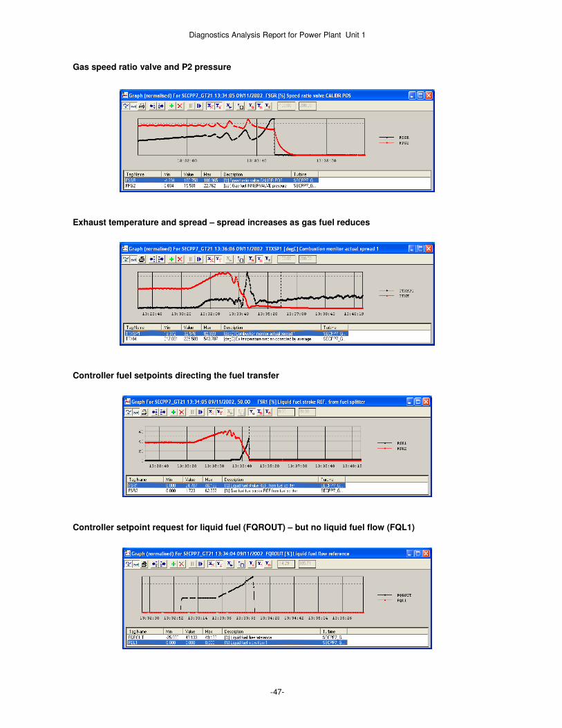
Diagnostics Analysis Report for Power Plant Unit 1
-47-
Gas speed ratio valve and P2 pressure
Exhaust temperature and spread – spread increases as gas fuel reduces
Controller fuel setpoints directing the fuel transfer
Controller setpoint request for liquid fuel (FQROUT) – but no liquid fuel flow (FQL1)

Diagnostics Analysis Report for Power Plant Unit 1
-48-
Flame lost on one flame detector
Finally, the gas control valve is nearly closed, and speed ratio valve is fully open. This indicates low gas pressure, and low gas supply to the turbine. There is still no liquid fuel supply. Hence, flame is then lost at flame detector 4, then flame detector 2 one second later, followed by a complete flame out trip. Flame lost on two flame detectors

Diagnostics Analysis Report for Power Plant Unit 1
-49-
Analysis During the fuel transfer there are problems with low and unstable gas fuel pressure. However, critically there is no liquid fuel supply, so the turbine eventually trips on flame out as the gas fuel is reduced but no liquid fuel is supplied to replace it. This was an operational problem, as it appears the manual stop valve for the liquid fuel was off when a fuel transfer was attempted. Hence it failed. Recommendations Ensure that all liquid fuel isolation valves are open before attempting a liquid fuel start or gas to liquid fuel transfer.
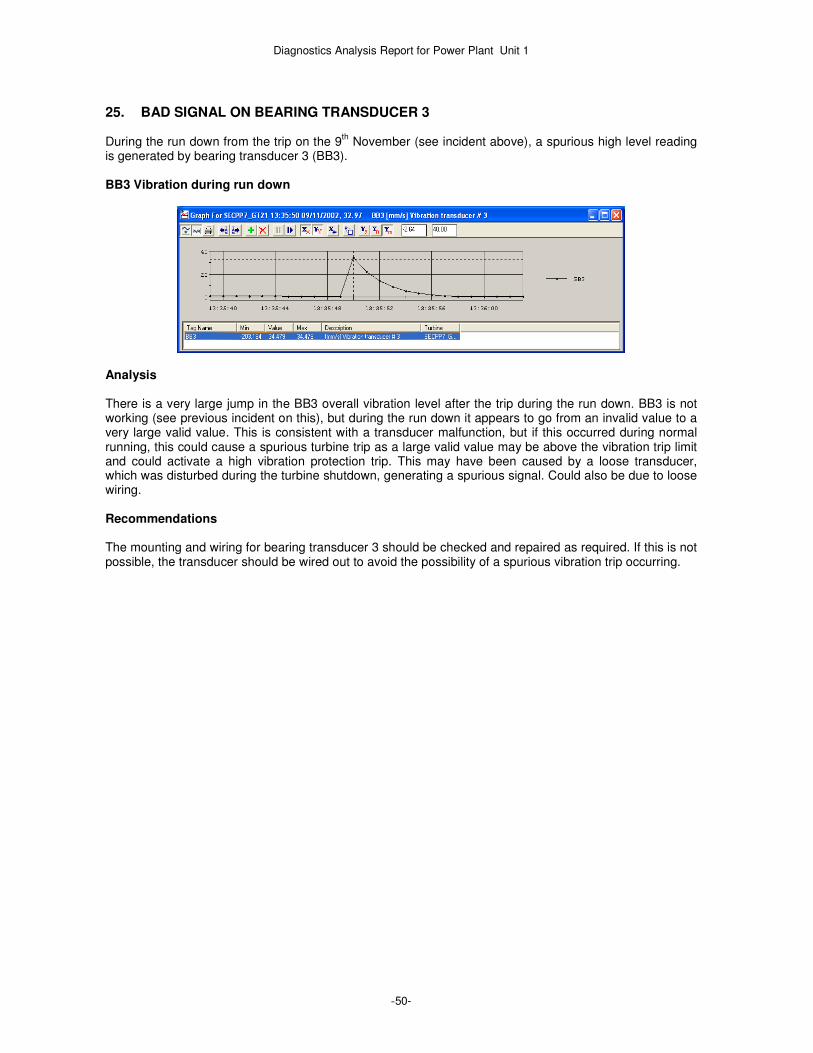
Diagnostics Analysis Report for Power Plant Unit 1
-50-
25. BAD SIGNAL ON BEARING TRANSDUCER 3 During the run down from the trip on the 9
th November (see incident above), a spurious high level reading
is generated by bearing transducer 3 (BB3). BB3 Vibration during run down
Analysis There is a very large jump in the BB3 overall vibration level after the trip during the run down. BB3 is not working (see previous incident on this), but during the run down it appears to go from an invalid value to a very large valid value. This is consistent with a transducer malfunction, but if this occurred during normal running, this could cause a spurious turbine trip as a large valid value may be above the vibration trip limit and could activate a high vibration protection trip. This may have been caused by a loose transducer, which was disturbed during the turbine shutdown, generating a spurious signal. Could also be due to loose wiring. Recommendations The mounting and wiring for bearing transducer 3 should be checked and repaired as required. If this is not possible, the transducer should be wired out to avoid the possibility of a spurious vibration trip occurring.

Diagnostics Analysis Report for Power Plant Unit 1
-51-
26. LIQUID FUEL CONTROL FAULT
TIGER detects several controller alarms relating to liquid fuel. However, the turbine is stopped and no liquid fuel has been requested. TIGER Diagnostic Messages 08:25:36 23/11/2002 § Liquid fuel flow high [L60FFLH] change from 0 to 1 08:25:37 23/11/2002 § Liquid fuel flow high [L60FFLH] change from 1 to 0 08:25:45 23/11/2002 § Liquid fuel bypass valve flow detected trouble alarm [L3LFBSQ] change from 0 to 1 08:25:45 23/11/2002 § Liquid fuel control fault [L3LFLT] change from 0 to 1
TIGER again detects several controller alarms relating to liquid fuel. However, the turbine is stopped and no liquid fuel has been requested. There appears to be some fuel flow that may be going through a bypass valve. It does appear that a liquid fuel start was attempted, but was locked out due to hydraulic pressure problems or due to high startup fuel flow. TIGER Diagnostic Messages 15:04:06 23/11/2002 § Liquid fuel stop valve closed [L33FL1C] change from 1 to 0 15:04:06 23/11/2002 » Liquid fuel system startup 15:04:06 23/11/2002 § Hydraulic protective trouble [L86HD] change from 0 to 1 15:04:07 23/11/2002 § Master protective startup lockout [L86MP] change from 0 to 1 15:04:15 23/11/2002 § Liquid fuel flow high [L60FFLH] change from 0 to 1 15:04:17 23/11/2002 » Startup fuel flow excessive trip 15:04:17 23/11/2002 § Liquid fuel control fault [L3LFLT] change from 0 to 1 15:04:18 23/11/2002 § Liquid fuel bypass valve flow detected trouble alarm [L3LFBSQ] change from 0 to 1 15:04:24 23/11/2002 § Liquid fuel stop valve closed [L33FL1C] change from 0 to 1 15:04:24 23/11/2002 » Liquid fuel system shutdown
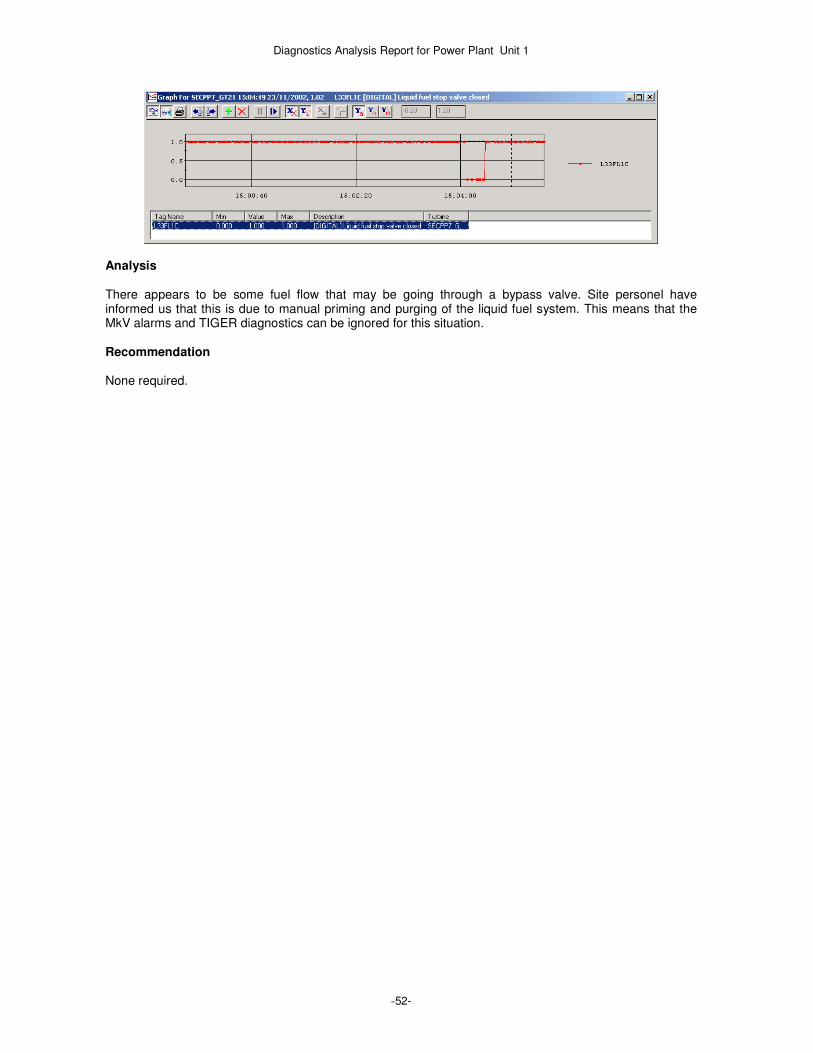
Diagnostics Analysis Report for Power Plant Unit 1
-52-
Analysis There appears to be some fuel flow that may be going through a bypass valve. Site personel have informed us that this is due to manual priming and purging of the liquid fuel system. This means that the MkV alarms and TIGER diagnostics can be ignored for this situation. Recommendation None required.

Diagnostics Analysis Report for Power Plant Unit 1
-53-
27. HIGH WHEEL SPACE TEMPERATURE ALARMS
TIGER detects several controller alarms relating to high wheelspace temperatures. These alarms are related to the TIGER diagnostic warnings on the wheelspace thermocouples, reported in the previous sections of this report. These warnings occur frequently, normally occurring when turbine load is high, and ambient temperatures are also high. TIGER Wheelspace Screen – example of high temperatures
Wheelspace and exhaust temperatures increasing and triggering alarm
TIGER Diagnostic Messages 01:57:03 24/10/2002 [WHEELSPACE_HI_TEMP0,1] Wheelspace temperature too high 02:33:01 24/10/2002 [WHEELSPACE_HI_TEMP0,1] Wheelspace temperature too high 22:46:34 24/10/2002 [WHEELSPACE_HI_TEMP0,1] Wheelspace temperature too high 02:38:07 26/10/2002 [WHEELSPACE_HI_TEMP0,1] Wheelspace temperature too high 02:56:31 26/10/2002 [WHEELSPACE_HI_TEMP0,1] Wheelspace temperature too high 07:00:51 26/10/2002 [WHEELSPACE_HI_TEMP0,1] Wheelspace temperature too high 07:31:08 26/10/2002 [WHEELSPACE_HI_TEMP0,1] Wheelspace temperature too high 07:39:12 26/10/2002 [WHEELSPACE_HI_TEMP0,1] Wheelspace temperature too high 08:08:47 26/10/2002 [WHEELSPACE_HI_TEMP0,1] Wheelspace temperature too high 08:52:28 26/10/2002 [WHEELSPACE_HI_TEMP0,1] Wheelspace temperature too high 14:44:57 26/10/2002 [WHEELSPACE_HI_TEMP0,1] Wheelspace temperature too high
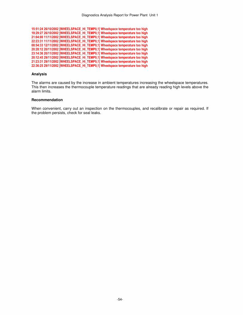
Diagnostics Analysis Report for Power Plant Unit 1
-54-
15:51:24 26/10/2002 [WHEELSPACE_HI_TEMP0,1] Wheelspace temperature too high 19:29:27 26/10/2002 [WHEELSPACE_HI_TEMP0,1] Wheelspace temperature too high 21:04:00 11/11/2002 [WHEELSPACE_HI_TEMP0,1] Wheelspace temperature too high 22:23:31 11/11/2002 [WHEELSPACE_HI_TEMP0,1] Wheelspace temperature too high 08:54:33 12/11/2002 [WHEELSPACE_HI_TEMP0,1] Wheelspace temperature too high 20:28:12 20/11/2002 [WHEELSPACE_HI_TEMP0,1] Wheelspace temperature too high 23:14:36 20/11/2002 [WHEELSPACE_HI_TEMP0,1] Wheelspace temperature too high 20:12:45 29/11/2002 [WHEELSPACE_HI_TEMP0,1] Wheelspace temperature too high 21:23:31 29/11/2002 [WHEELSPACE_HI_TEMP0,1] Wheelspace temperature too high 22:36:25 29/11/2002 [WHEELSPACE_HI_TEMP0,1] Wheelspace temperature too high
Analysis The alarms are caused by the increase in ambient temperatures increasing the wheelspace temperatures. This then increases the thermocouple temperature readings that are already reading high levels above the alarm limits. Recommendation When convenient, carry out an inspection on the thermocouples, and recalibrate or repair as required. If the problem persists, check for seal leaks.

Diagnostics Analysis Report for Power Plant Unit 1
-55-
28. GAS FUEL P2 PRESSURE INSTABILITY
TIGER detects these pressure instablities several times during the selected period. TIGER Diagnostic Messages
18:42:54 30/10/2002 [GFS_IVP_OSC0,1] Gas fuel - significant intervalve pressure oscillation 10:43:23 03/11/2002 [GFS_IVP_OSC0,1] Gas fuel - significant intervalve pressure oscillation 10:43:39 03/11/2002 [GFS_IVP_OSC0,1] Gas fuel - significant intervalve pressure oscillation 10:44:04 03/11/2002 [GFS_IVP_OSC0,1] Gas fuel - significant intervalve pressure oscillation 11:47:11 04/11/2002 [GFS_IVP_OSC0,1] Gas fuel - significant intervalve pressure oscillation 11:47:27 04/11/2002 [GFS_IVP_OSC0,1] Gas fuel - significant intervalve pressure oscillation 11:40:50 09/11/2002 [GFS_IVP_OSC0,1] Gas fuel - significant intervalve pressure oscillation 11:41:09 09/11/2002 [GFS_IVP_OSC0,1] Gas fuel - significant intervalve pressure oscillation 14:24:19 13/11/2002 [GFS_IVP_OSC0,1] Gas fuel - significant intervalve pressure oscillation 13:07:28 17/11/2002 [GFS_IVP_OSC0,1] Gas fuel - significant intervalve pressure oscillation 01:45:25 23/11/2002 [GFS_IVP_OSC0,1] Gas fuel - significant intervalve pressure oscillation 09:53:51 24/11/2002 [GFS_IVP_OSC0,1] Gas fuel - significant intervalve pressure oscillation
An example of the P2 pressure instability. TIGER Diagnostic Messages
01:45:23 23/11/2002 » Generator breaker trip 01:45:23 23/11/2002 § Generator breaker closure [L52GX] change from 1 to 0 01:45:23 23/11/2002 » Generator disconnected from grid - circuit breaker opened 01:45:24 23/11/2002 § Turbine significant speed increase detected 01:45:24 23/11/2002 § Exhaust temperature significant increase 01:45:24 23/11/2002 » Exhaust temperature - rapid increase 01:45:24 23/11/2002 » Exhaust temperature - significant oscillation detected 01:45:25 23/11/2002 § Gas fuel control valve set point significant decrease 01:45:25 23/11/2002 § Gas fuel flow significant decrease 01:45:25 23/11/2002 § Gas fuel intervalve pressure significant increase 01:45:25 23/11/2002 » Gas fuel - significant intervalve pressure oscillation 01:45:25 23/11/2002 § Gas fuel control valve position significant decrease
Generator Breaker and Speed
Gas fuel P2 pressure and P2 pressure setpoint
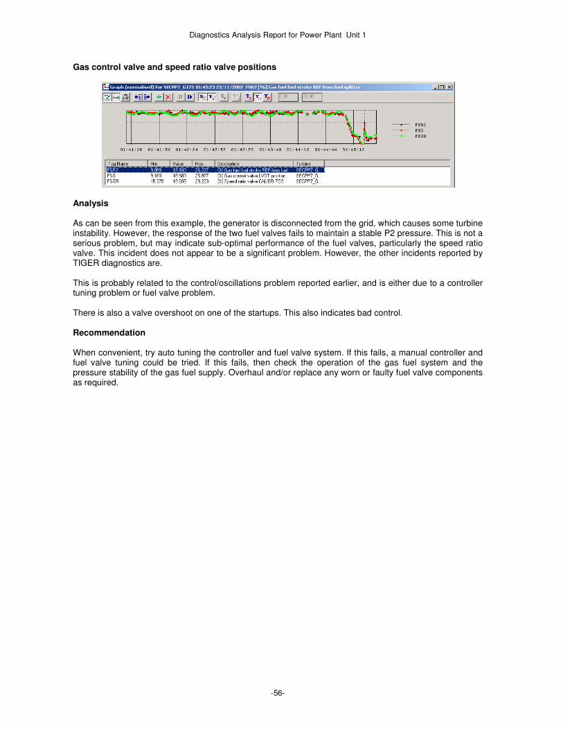
Diagnostics Analysis Report for Power Plant Unit 1
-56-
Gas control valve and speed ratio valve positions
Analysis As can be seen from this example, the generator is disconnected from the grid, which causes some turbine instability. However, the response of the two fuel valves fails to maintain a stable P2 pressure. This is not a serious problem, but may indicate sub-optimal performance of the fuel valves, particularly the speed ratio valve. This incident does not appear to be a significant problem. However, the other incidents reported by TIGER diagnostics are. This is probably related to the control/oscillations problem reported earlier, and is either due to a controller tuning problem or fuel valve problem. There is also a valve overshoot on one of the startups. This also indicates bad control. Recommendation When convenient, try auto tuning the controller and fuel valve system. If this fails, a manual controller and fuel valve tuning could be tried. If this fails, then check the operation of the gas fuel system and the pressure stability of the gas fuel supply. Overhaul and/or replace any worn or faulty fuel valve components as required.

Diagnostics Analysis Report for Power Plant Unit 1
-57-
29. CONTROLLER COMPARTMENT HIGH TEMPERATURE ALARMS
TIGER detects these high temperature alarms continuously. An example sequence from the 29th
November is shown below. TIGER Diagnostic Messages 00:18:17 29/11/2002 § Control panel temperature high [L26CTH-ALM] change from 0 to 1 00:50:43 29/11/2002 § Control panel temperature high [L26CTH-ALM] change from 0 to 1 01:17:29 29/11/2002 § Control compartment temperature - high [L26CTH] change from 0 to 1 01:25:11 29/11/2002 § Control compartment temperature - high [L26CTH] change from 0 to 1 01:43:24 29/11/2002 § Control panel temperature high [L26CTH-ALM] change from 0 to 1 01:49:12 29/11/2002 § Control compartment temperature - high [L26CTH] change from 0 to 1 02:05:19 29/11/2002 § Control panel temperature high [L26CTH-ALM] change from 0 to 1 02:06:16 29/11/2002 § Control compartment temperature - high [L26CTH] change from 0 to 1 02:41:34 29/11/2002 § Control panel temperature high [L26CTH-ALM] change from 0 to 1 02:42:49 29/11/2002 § Control panel temperature high [L26CTH-ALM] change from 0 to 1 02:45:29 29/11/2002 § Control panel temperature high [L26CTH-ALM] change from 0 to 1 03:00:59 29/11/2002 § Control compartment temperature - high [L26CTH] change from 0 to 1 04:11:56 29/11/2002 § Control panel temperature high [L26CTH-ALM] change from 0 to 1 04:22:18 29/11/2002 § Control compartment temperature - high [L26CTH] change from 0 to 1
The monthly trend graph for November indicates how the controller compartment temperature alarms are frequently triggered. Speed is included to indicate when the turbine is running or stopped. Turbine compartment cooling fan, controller compartment high temperature alarms and speed.
The monthly trend graph for October indicates how the controller compartment temperature alarms are triggered for extended periods. Speed is included to indicate when the turbine is running or stopped. Turbine compartment cooling fan, controller compartment high temperature alarms and speed.

Diagnostics Analysis Report for Power Plant Unit 1
-58-
Analysis As can be seen from the two trend graphs, the controller compartment temperature alarm is frequently triggered. This indicates that the compartment temperatures are too high. This may well affect the reliability of the controller, and could lead to faults developing. The two trend graphs also indicate that the compartment fans appear to be running, and the fact the alarms persist for longer during the October period probably indicates that the higher ambient temperatures then are increasing the compartment temperatures above the alarm limit for longer periods. Recommendation Check the compartment fans and cooling systems, and repair or upgrade as necessary.

Diagnostics Analysis Report for Power Plant Unit 1
-59-
30. GENERATOR EXCITER RECTIFIER COOLING FAN ALARMS This alarm is currently occurring frequently, as indicated from the data for the 7
th January.
TIGER Diagnostic Messages 08:21:11 07/01/2003 [L30EK-ALM0,1] Exciter RECT cooling fan trouble ALM (L30EK-ALM) change from 0 to 1 10:37:14 07/01/2003 [L30EK-ALM0,1] Exciter RECT cooling fan trouble ALM (L30EK-ALM) change from 0 to 1 10:51:24 07/01/2003 [L30EK-ALM0,1] Exciter RECT cooling fan trouble ALM (L30EK-ALM) change from 0 to 1 10:57:27 07/01/2003 [L30EK-ALM0,1] Exciter RECT cooling fan trouble ALM (L30EK-ALM) change from 0 to 1 15:51:21 07/01/2003 [L30EK-ALM0,1] Exciter RECT cooling fan trouble ALM (L30EK-ALM) change from 0 to 1 16:57:59 07/01/2003 [L30EK-ALM0,1] Exciter RECT cooling fan trouble ALM (L30EK-ALM) change from 0 to 1 16:58:03 07/01/2003 [L30EK-ALM0,1] Exciter RECT cooling fan trouble ALM (L30EK-ALM) change from 0 to 1 16:58:05 07/01/2003 [L30EK-ALM0,1] Exciter RECT cooling fan trouble ALM (L30EK-ALM) change from 0 to 1 16:58:23 07/01/2003 [L30EK-ALM0,1] Exciter RECT cooling fan trouble ALM (L30EK-ALM) change from 0 to 1 16:58:34 07/01/2003 [L30EK-ALM0,1] Exciter RECT cooling fan trouble ALM (L30EK-ALM) change from 0 to 1 16:59:12 07/01/2003 [L30EK-ALM0,1] Exciter RECT cooling fan trouble ALM (L30EK-ALM) change from 0 to 1 18:06:54 07/01/2003 [L30EK-ALM0,1] Exciter RECT cooling fan trouble ALM (L30EK-ALM) change from 0 to 1 19:24:29 07/01/2003 [L30EK-ALM0,1] Exciter RECT cooling fan trouble ALM (L30EK-ALM) change from 0 to 1
Analysis As can be seen from the TIGER diagnostics, this alarm is now occurring frequently. This could lead to overheating problems with the exciter, and therefore potential generator failure. The fan cuts outs could be due to fans overheating due to dirty filters etc. Recommendation Check and clean exciter air filters and fans and repair as necessary.

Diagnostics Analysis Report for Power Plant Unit 1
-60-
31. GENERATOR AND GRID - FREQUENCY AND VOLTAGE DROPOUTS These drop outs are currently occurring frequently, as indicated from the data for the 7
th January 2003. The
daily trend graph for this day shows the dropouts on the grid voltage and frequency during the day. These dropouts also occur on the generator voltage, but do not occur on the generator frequency, turbine speed or power. Daily trend - grid voltage.
Daily trend - grid frequency.
Selecting a particular dropout at around 14:00, we can see that it is detected by the various TIGER diagnostics. However, as can be seen from the graphs below, there is no effect on speed or power. TIGER diagnostics also detect a discrepancy between generator and grid voltage and generator and grid frequency. TIGER Diagnostic Messages 14:05:46 08/01/2003 § Grid frequency significant drop detected 14:05:46 08/01/2003 § Grid voltage significant drop detected 14:05:46 08/01/2003 § BUS_PT FREQ [SFL2] too low. Limit 59.40 Hz 14:05:46 08/01/2003 » Grid frequency too low 14:05:46 08/01/2003 § System line voltage [SVL] too low. Limit 12.40 KV 14:05:46 08/01/2003 » Grid voltage too low 14:05:46 08/01/2003 § Generator line volts [DV] too low. Limit 12.40 KV 14:05:47 08/01/2003 § Generator frequency and grid reference diverged for 1 seconds by more than 0.40 14:05:47 08/01/2003 § Generator voltage and line voltage diverged for 1 seconds by more than 1.00 14:05:48 08/01/2003 § Grid frequency significant rise detected 14:05:48 08/01/2003 » Grid - significant frequency oscillation 14:05:48 08/01/2003 » Grid spike - significant voltage drop 14:05:48 08/01/2003 § Grid voltage significant rise detected 14:05:48 08/01/2003 » Grid spike - significant voltage increase 14:05:48 08/01/2003 » Grid voltage spike oscillation 14:05:48 08/01/2003 » Grid voltage disturbance detected

Diagnostics Analysis Report for Power Plant Unit 1
-61-
Grid and generator voltage.
Grid and generator frequency.
On a normalised scale, both turbine speed and power just show noise with no transients related to the grid electrical disturbances indicated by the various electrical sensor data graphed above. Turbine speed and power (normalised scale).
Analysis This is most likely a problem with the grid frequency and voltage sensors or controller operation, as there is no perceived physical effect on turbine operation, i.e. on speed (for frequency) and power (for frequency and voltage). It also seems unlikely that grid voltage and frequency actually drop to zero and back within a few seconds. As these dropouts occur at the same time as the exhaust temperature thermocouple dropouts reported previously, they are probably being caused by the same controller RST dropouts faults. Recommendation Check the relevant controller cards and connections and clean the controller boards and housing with compressed air. If necessary, replace any faulty controller processor components.