
Tig 150i Tig 200i - esab.com · ESAB AB, Welding Equipment, SE--695 81 Laxå, Sweden, gives its...
28
GB Valid for serial no. 620--xxx--xxxx 0459 264 201 GB 060523 Tig 150i Tig 200i Caddyt TA34 Instruction manual
Transcript of Tig 150i Tig 200i - esab.com · ESAB AB, Welding Equipment, SE--695 81 Laxå, Sweden, gives its...

GB
Valid for serial no. 620--xxx--xxxx0459 264 201 GB 060523
Tig 150iTig 200iCaddyt TA34
Instruction manual

-- 2 --TOCe
Rights reserved to alter specifications without notice.
1 DIRECTIVE 3. . . . . . . . . . . . . . . . . . . . . . . . . . . . . . . . . . . . . . . . . . . . . . . . . . . . . . . .2 SAFETY 3. . . . . . . . . . . . . . . . . . . . . . . . . . . . . . . . . . . . . . . . . . . . . . . . . . . . . . . . . . .3 INTRODUCTION 5. . . . . . . . . . . . . . . . . . . . . . . . . . . . . . . . . . . . . . . . . . . . . . . . . . .
3.1 Equipment 5. . . . . . . . . . . . . . . . . . . . . . . . . . . . . . . . . . . . . . . . . . . . . . . . . . . . . . . . . . . . . . . .
4 TECHNICAL DATA 5. . . . . . . . . . . . . . . . . . . . . . . . . . . . . . . . . . . . . . . . . . . . . . . . .4.1 Settings 6. . . . . . . . . . . . . . . . . . . . . . . . . . . . . . . . . . . . . . . . . . . . . . . . . . . . . . . . . . . . . . . . . .
5 INSTALLATION 7. . . . . . . . . . . . . . . . . . . . . . . . . . . . . . . . . . . . . . . . . . . . . . . . . . . .5.1 Placing 7. . . . . . . . . . . . . . . . . . . . . . . . . . . . . . . . . . . . . . . . . . . . . . . . . . . . . . . . . . . . . . . . . . .5.2 Rating plate 7. . . . . . . . . . . . . . . . . . . . . . . . . . . . . . . . . . . . . . . . . . . . . . . . . . . . . . . . . . . . . . .5.3 Mains power supply 7. . . . . . . . . . . . . . . . . . . . . . . . . . . . . . . . . . . . . . . . . . . . . . . . . . . . . . . .5.4 Connections and control devices 8. . . . . . . . . . . . . . . . . . . . . . . . . . . . . . . . . . . . . . . . . . . .
6 OPERATION 9. . . . . . . . . . . . . . . . . . . . . . . . . . . . . . . . . . . . . . . . . . . . . . . . . . . . . . .6.1 Control panel TA 34 9. . . . . . . . . . . . . . . . . . . . . . . . . . . . . . . . . . . . . . . . . . . . . . . . . . . . . . . .6.2 Overheating protection 10. . . . . . . . . . . . . . . . . . . . . . . . . . . . . . . . . . . . . . . . . . . . . . . . . . . . .6.3 Hidden functions 10. . . . . . . . . . . . . . . . . . . . . . . . . . . . . . . . . . . . . . . . . . . . . . . . . . . . . . . . . .
7 WELDING 11. . . . . . . . . . . . . . . . . . . . . . . . . . . . . . . . . . . . . . . . . . . . . . . . . . . . . . . . .7.1 TIG welding 11. . . . . . . . . . . . . . . . . . . . . . . . . . . . . . . . . . . . . . . . . . . . . . . . . . . . . . . . . . . . . . .7.2 MMA welding 15. . . . . . . . . . . . . . . . . . . . . . . . . . . . . . . . . . . . . . . . . . . . . . . . . . . . . . . . . . . . .
8 WELDING DATA MEMORY 16. . . . . . . . . . . . . . . . . . . . . . . . . . . . . . . . . . . . . . . . . .9 MAINTENANCE 16. . . . . . . . . . . . . . . . . . . . . . . . . . . . . . . . . . . . . . . . . . . . . . . . . . . .
9.1 Cleaning the dust filter 16. . . . . . . . . . . . . . . . . . . . . . . . . . . . . . . . . . . . . . . . . . . . . . . . . . . . .
10 FAULT TRACING 17. . . . . . . . . . . . . . . . . . . . . . . . . . . . . . . . . . . . . . . . . . . . . . . . . . .10.1 Fault codes 17. . . . . . . . . . . . . . . . . . . . . . . . . . . . . . . . . . . . . . . . . . . . . . . . . . . . . . . . . . . . . . .
11 ORDERING SPARE PARTS 18. . . . . . . . . . . . . . . . . . . . . . . . . . . . . . . . . . . . . . . . . .DIAGRAM 20. . . . . . . . . . . . . . . . . . . . . . . . . . . . . . . . . . . . . . . . . . . . . . . . . . . . . . . . . . . .ORDERING NUMBER 24. . . . . . . . . . . . . . . . . . . . . . . . . . . . . . . . . . . . . . . . . . . . . . . . .SPARE PARTS LIST 25. . . . . . . . . . . . . . . . . . . . . . . . . . . . . . . . . . . . . . . . . . . . . . . . . . .ACCESSORIES 26. . . . . . . . . . . . . . . . . . . . . . . . . . . . . . . . . . . . . . . . . . . . . . . . . . . . . . .
-- 3 --bt27d2e
1 DIRECTIVE
DECLARATION OF CONFORMITYESAB AB, Welding Equipment, SE--695 81 Laxå, Sweden, gives its unreserved guarantee that weld-ing power source Tig 150i / Tig 200i from serial number 620 complies with standard IEC/EN 60974--1/--3, in accordance with the requirements of directive (73/23/EEC) and addendum (93/68/EEC) andwith standard IEC/EN 60974--10 in accordance with the requirements of directive (89/336/EEC) andaddendum (93/68/EEC).--------------------------------------------------------------------------------------------------------------------------------------
Kent EimbrodtGlobal Director Equipment and AutomationESAB AB695 81 LAXÅSWEDEN Tel: + 46 584 81000 Fax: + 46 584 411924
Laxå 2006--05--22
2 SAFETY
Users of ESAB welding equipment have the ultimate responsibility for ensuring that anyone whoworks on or near the equipment observes all the relevant safety precautions. Safety precautionsmust meet the requirements that apply to this type of welding equipment. The following recommen-dations should be observed in addition to the standard regulations that apply to the workplace.
All work must be carried out by trained personnel well--acquainted with the operation of the weldingequipment. Incorrect operation of the equipment may lead to hazardous situations which can resultin injury to the operator and damage to the equipment.
1. Anyone who uses the welding equipment must be familiar with:S its operationS location of emergency stopsS its functionS relevant safety precautionsS welding
2. The operator must ensure that:S no unauthorised person is stationed within the working area of the equipment when it is
started up.S no--one is unprotected when the arc is struck
3. The workplace must:S be suitable for the purposeS be free from draughts
4. Personal safety equipmentS Always wear recommended personal safety equipment, such as safety glasses, flame--proof
clothing, safety gloves.S Do not wear loose--fitting items, such as scarves, bracelets, rings, etc., which could become
trapped or cause burns.
5. General precautionsS Make sure the return cable is connected securely.S Work on high voltage equipment may only be carried out by a qualified electrician.S Appropriate fire extinquishing equipment must be clearly marked and close at hand.
GB

-- 4 --bt27d2e
WARNING
READ AND UNDERSTAND THE INSTRUCTION MANUAL BEFORE INSTALLING OR OPERATING.
ARC WELDING AND CUTTING CAN BE INJURIOUS TO YOURSELF AND OTHERS. TAKE PRECAU-TIONS WHEN WELDING. ASK FOR YOUR EMPLOYER’S SAFETY PRACTICES WHICH SHOULD BEBASED ON MANUFACTURERS’ HAZARD DATA.
ELECTRIC SHOCK -- Can killS Install and earth the welding unit in accordance with applicable standards.S Do not touch live electrical parts or electrodes with bare skin, wet gloves or wet clothing.S Insulate yourself from earth and the workpiece.S Ensure your working stance is safe.
FUMES AND GASES -- Can be dangerous to healthS Keep your head out of the fumes.S Use ventilation, extraction at the arc, or both, to take fumes and gases away from your breathing zone
and the general area.
ARC RAYS -- Can injure eyes and burn skin.S Protect your eyes and body. Use the correct welding screen and filter lens and wear protective
clothing.S Protect bystanders with suitable screens or curtains.
FIRE HAZARDS Sparks (spatter) can cause fire. Make sure therefore that there are no inflammable materials nearby.
NOISE -- Excessive noise can damage hearingS Protect your ears. Use earmuffs or other hearing protection.S Warn bystanders of the risk.
MALFUNCTION -- Call for expert assistance in the event of malfunction.
PROTECT YOURSELF AND OTHERS!
ESAB can provide you with all necessary welding protection and accessories.
WARNING!Read and understand the instruction manual before installingor operating.
Do not use the power source for thawing frozen pipes.
WARNING!
This product is solely intended for arc welding.
Do not dispose of electrical equipment together with normal waste!In observance of European Directive 2002/96/EC on Waste Electrical and ElectronicEquipment and its implementation in accordance with national law, electrical equipmentthat has reached the end of its life must be collected separately and returned to anenvironmentally compatible recycling facility. As the owner of the equipment, you shouldget information on approved collection systems from our local representative.By applying this European Directive you will improve the environment and human health!
GB

-- 5 --bt27d2e
3 INTRODUCTIONThe Tig 150i/Tig 200i is a welding current power source based on the staticconverter technology intended TIG welding and welding with coated electrodes(MMA). The static converter technology contributes to low energy consumption, lowweight and small dimensions. Advanced electronics with microcomputer controlproduces e.g. rapid regulation and top--class welding properties.
3.1 EquipmentThe Tig 150i/Tig 200i is supplied with 3 m of mains cable and an instruction manual.ESAB’s accessories for the product can be found on page 26.
4 TECHNICAL DATA
Tig 150i Tig 200iMains voltage 230V, 1∼ 50/60 Hz 230V, 1∼ 50/60 HzFuse (delayed--action) 16 A 16 APrimary current Imax 36 A 36 APrimary current Ieff 21 A 21 AVoltage/current range(TIG)(MMA)
3 A / 10 V --150 A / 16 V4 A / 20 V --150 A / 26 V
3 A / 10 V -- 200 A / 18 V4 A / 20 V -- 150 A / 26 V
Maximum permissible load at TIG25% duty cycle35% duty cycle60% duty cycle100% duty cycle
150 A / 16 V120 A / 15 V95 A / 14 V
200 A / 18 V180 A / 17 V140 A / 15,5 V110 A / 14,5 V
Maximum permissible load at MMA25% duty cycle35% duty cycle60% duty cycle100% duty cycle
150 A / 26 V140 A / 25,5 V110 A / 24,5 V90 A / 23,5 V
150 A / 26 V140 A / 25,5V110 A / 24,5V90 A / 23,5V
Power factor at maximum current 0,62 0,62Efficiency at maximum current 77 % 79 %Open--circuit voltage 71 -- 78 V 71 -- 78 VOperating temperature --10˚C -- + 40˚C --10˚C -- + 40˚CConstant A--weighed soundpressure
<70 db <70 db
Dimensions, l x b x h 394 x 267 x 274 mm 394 x 267 x 274 mmWeight 10 kg 10 kgEnclosure class IP 23C IP 23CApplication class
Duty cycleThe duty cycle refers to the time as a percentage of a ten--minute period that you can weld at a cer-tain load without overloading.
Enclosure classThe IP code indicates the enclosure class, i. e. the degree of protection against penetration by solidobjects or water. Equipment marked IP23 is designed for indoor and outdoor use.
Application class
The symbol indicates that the power source is designed for use in areas with increasedelectrical hazard.
GB

-- 6 --bt27d2e
4.1 Settings
4.1.1 TIG welding without pulsing
Settings Setting range In steps of: Default value
Welding method TIG, TIG pulse or MMA -- TIG
2/4 stroke * 2 stroke or 4 stroke -- 2 stroke
HF / LiftArct * HF or Liftarct -- LiftArct
Gas pre--flow 0 -- 5 s 0.1 s 0.5 s
Slope up time 0 --10 s 0.1 s 0.0 s
Slope down time 0 --10 s 0.1 s 1.0 s
Gas post--flow 0 -- 25 s 0.1 s 2.0 s
Current Tig 150i 3 --150 A 1 A 60 A
Current Tig 200i 3 --200 A 1 A 60 A
4.1.2 TIG welding with pulsing
Settings Setting range In steps of: Default value
Welding method * TIG, TIG pulse or MMA -- TIG
2/4 stroke * 2 stroke or 4 stroke -- 2 stroke
HF / LiftArct * HF or Liftarct -- LiftArct
Gas pre--flow 0 -- 5 s 0.1 s 0.5 s
Slope up time 0 -- 10 s 0.1 s 0.0 s
Slope down time 0 -- 10 s 0.1 s 1.0 s
Gas post--flow 0 -- 25 s 0.1 s 2.0 s
Pulse time
Micro pulse**
0.1 -- 2.5 s
0.001 -- 0.250 s
0.01 s
0.001 s
1.0 s
Background time
Micro pulse**
0.1 -- 2.5 s
0.001 -- 0.250 s
0.01 s
0.001 s
1.0 s
Pulse current Tig 150i 3 -- 150 A 1 A 60 A
Background current Tig 150i 3 -- 150 A 1 A 20 A
Pulse current Tig 200i 3 -- 200 A 1 A 60 A
Background current Tig 200i 3 -- 200 A 1 A 20 A
4.1.3 MMA settings
Settings Setting range In steps of: Default value
Welding method TIG / MMA -- TIG
Arc Force 0 -- 99% 1% 5%
Drop welding I / 0 -- 0
Regulator type ArcPlust I / 0 -- I
Hot start 0 -- 99% 1% 0%
Current Tig 150i 4 -- 150 A 2 A 100 A
Current Tig 200i 4 -- 150 A 2 A 100 A
*) These functions cannot be changed while welding is in progress.
**) Gas pre--flow time and micro pulse are hidden functions, see page 10 .
GB

-- 7 --bt27d2e
5 INSTALLATION
The installation must be executed by a professional.
WARNING!This product is intended for industrial use. In a domestic environment this product may cause radiointerference. It is the user’s responsibility to take adequate precautions.
Note!Connect the power source to the electricity mains with a network impedance of 0.210 ohm or lower. If thenetwork impedance is higher, there is a risk of flicker in the illuminators.
5.1 Placing
Place the power source so that its cooling air inlets and outlets are not obstructed.
5.2 Rating plate
The rating plate is located on the underside of the power source.
5.3 Mains power supply
Make sure that the welding power source is connected to the correct supply voltageand that it is protected by the correct fuse rating. The standards for the country inquestion must be complied with as regards the mains cable area. A protective earthconnection must be made in accordance with regulations.
5.3.1 Recommended fuse sizes and minimum cable areas
Tig 150i Tig 200i
Mains voltage 230 V ¦10 %, 1--phase 230 V ¦10 %, 1--phase
Mains frequency 50--60 Hz 50--60 Hz
Fuse (delayed--action)85A 35% duty cycle MMA
120A 20% duty cycle MMA
150A 25% duty cycle MMA
10 A
16 A
20 A*)
10 A
16 A
20 A
Mains cable, area 3 x 2.5 mm2 3 x 2.5 mm2
Welding cable, area MMA 16 mm2 16 mm2
Welding cable, area TIG 16 mm2 25 mm2
*) NOTE! The mains plug is approved for maximum 16A.North American version: The mains cable is approved for maximun 18 A.
Note!The cable area and fuse rating above comply with Swedish regulations. Use the welding power sourcein accordance with the relevant national regulations.
GB

-- 8 --bt27d2e
5.4 Connections and control devices
1 Control panel, 6 Gas hose connection to the TIG torch
2 TIG: Return cable connection (+)MMA: Welding cable connection (--)
7 Connection for the TIG torch switch
3 Remote control unit connection 8 Gas bottle connection
4 MMA: Return cable connection (--) 9 Mains cable
5 TIG torch connection (--) 10 Mains power supply switch
2 and 4 are used for welding current supply and return cable connection during MMA welding
GB

-- 9 --bt27d2e
6 OPERATION
General safety regulations for the handling of the equipment can be found onpage 3. Read through before you start using the equipment!
6.1 Control panel TA 34
On the upper side of the power source there is a control panel for choosing functionsand setting parameters. This comprises a display, setting knob, LEDs andpushbuttons. Using the pushbuttons, it is possible to move between the variousfunctions. The selected function is indicated by the relevant LED lighting up.
The power source checks the LEDs and all segments in the display when mainswitch is turned on. The machine type and program version are alsodisplayed.
A Ampere/Volt B LED (green) mains voltage
C Remote control D LED (yellow) overheating
E Data display F Knob for setting data.Increase (+) or Decrease (--) selected bythe function pushbuttons
6.1.1 Function symbols in the control panel
TIG Direct current TIG HF 2 stroke
MMA Pulse LiftArc 4 stroke
Slope up Slope down Gas post--flow
GB

-- 10 --bt27d2e
6.2 Overheating protection
The welding power source has a thermal overload trip which operates if thetemperature becomes too high, interrupting the welding current and lighting ayellow indicating lamp on the front of the power source. The thermal overload tripresets automatically when the temperature has fallen.
6.3 Hidden functions
The Tig 150i/Tig 200i is supplied with ArcPlus, a new type of control that, duringMMA welding, produces a more intensive, more concentrated and calmer arc. Itrecovers more quickly after a drop short--circuit, which reduces the risk of theelectrode becoming caught.
The machine is also equipped with Arc Force, which means that the power source’sdynamics can be adjusted, softer or harder depending on the type of electrode andaccording to preference. However, the Arc Plust regulator’s good properties meanthat there is only reason to alter the Arc Force setting in exceptional cases.
The Tig 150i/Tig 200i includes additional setting options that are obtained by pres-
sing and simultaneously for 1 second.
Access to the setting options (A --H) are displayed by pressing or .Set the values or function by turning the knob.
Hidden functions TIG welding
For TIG, the following options under the double press function can be found underthe letters:
A = setting gas pre--flow time in secondsb = setting micropulse (TIG pulse Off= 0 or On=1
The following welding data setting options for MMA can be found under the letters:
Hidden functions MMA welding
C = setting ArcForce value in percentD = setting Drop welding Off=0 or On =1F = setting regulator ArcPlust Off=1 or On =0H = setting Hot Start value in percent
Reset additional settings by pressing and simultaneously for1 second.
GB

-- 11 --bt27d2e
7 WELDING
7.1 TIG welding
During TIG welding, the return cable must be connected to (+) and the TIG torch to(--). If they are connected in reverse, the tungsten electrode will melt.
Pulsing is used for improved control of the weld pool and the solidification process. Thepulse frequency is set so slow that the weld pool has time to solidify at least partially be-tween each pulse. In order to set pulsing, four parameters are required: pulse time,background time, pulse current and background current.
7.1.1 2 stroke
Gas pre--flow Slopeup
Slope down Gas post--flow
Functions when using 2 stroke control of the welding torch.
In the 2 stroke control mode, pressing the trigger switch starts gas pre--flow (if used)and strikes the arc (1). The current rises to the set value (as controlled by the slopeup function, if in operation). Releasing the trigger switch (2) reduces the current (orstarts slope down if in operation) and extinguishes the arc. Gas post--flow follows if itis in operation.
7.1.2 4 stroke
Gas pre--flow Slopeup
Slope down Gas post--flow
Functions when using 4 stroke control of the welding torch.
In the 4 stroke control mode, pressing the trigger switch starts gas pre--flow (if used)(1). At the end of the gas pre--flow time, the current rises to the pilot level (a fewampere), and the arc is struck. Releasing the trigger switch (2) increases the currentto the set value (with slope up, if in use). At the end of welding, the welder pressesthe trigger switch again (3), which reduces the current to pilot level again (with slopedown, if in use). Releasing the switch again (4) extinguishes the arc and starts gaspost--flow.
GB
-- 12 --bt27d2e
7.1.3 HF
The HF function strikes the arc by means of a spark from the electrode to theworkpiece as the electrode is brought closer to the workpiece.
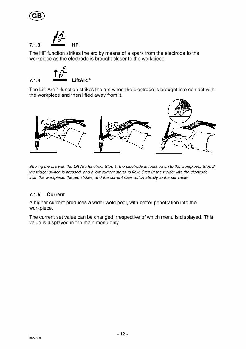
7.1.4 LiftArct
The Lift Arct function strikes the arc when the electrode is brought into contact withthe workpiece and then lifted away from it.
Striking the arc with the Lift Arc function. Step 1: the electrode is touched on to the workpiece. Step 2:the trigger switch is pressed, and a low current starts to flow. Step 3: the welder lifts the electrodefrom the workpiece: the arc strikes, and the current rises automatically to the set value.
7.1.5 Current
A higher current produces a wider weld pool, with better penetration into theworkpiece.
The current set value can be changed irrespective of which menu is displayed. Thisvalue is displayed in the main menu only.
GB
-- 13 --bt27d2e
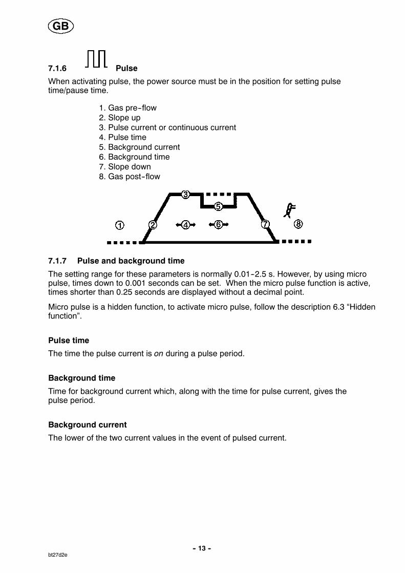
7.1.6 Pulse
When activating pulse, the power source must be in the position for setting pulsetime/pause time.
1. Gas pre--flow2. Slope up3. Pulse current or continuous current4. Pulse time5. Background current6. Background time7. Slope down8. Gas post--flow
7.1.7 Pulse and background time
The setting range for these parameters is normally 0.01--2.5 s. However, by using micropulse, times down to 0.001 seconds can be set. When the micro pulse function is active,times shorter than 0.25 seconds are displayed without a decimal point.
Micro pulse is a hidden function, to activate micro pulse, follow the description 6.3 “Hiddenfunction”.
Pulse time
The time the pulse current is on during a pulse period.
Background time
Time for background current which, along with the time for pulse current, gives thepulse period.
Background current
The lower of the two current values in the event of pulsed current.
GB

-- 14 --bt27d2e
Pulse currentA higher current produces a wider weld pool, with better penetration into theworkpiece.
The current set value can be changed irrespective of which menu is displayed. Thisvalue is displayed in the main menu only.
Current
Backgroundtime
Pulse current
Backgroundcurrent
Pulse time
Time
TIG welding with pulsing.
7.1.8 Remote control unitUsing the remote control unit socket on the machine, the current can be controlled remotelyfor both TIG and MMA.If pulsed current is chosen in TIG mode, it is the pulse current that is remotely controlled.The value set from the remote control unit is shown on the display by browsing to theposition where the current would have been set without the remote control unit.This is confirmed by the green LED lighting up.
7.1.9 Gas pre--flow
This controls the time during which shielding gas flows before the arc is struck.
7.1.10 Slope up
The slope up function means that, when the TIG arc strikes, the current rises slowlyto the set value. This provides ‘gentler’ heating of the electrode, and gives the weldera chance to position the electrode properly before the full current value is reached.
7.1.11 Slope down
TIG welding uses slope down, by which the current falls ’slowly’ over a controlledtime, to avoid craters and/or cracks when a weld is finished.
7.1.12 Gas post--flow
This controls the time during which shielding gas flows after the arc is extinguished.
GB

cmha2p11
cmha2p10
-- 15 --bt27d2e
7.2 MMA welding
The Tig 150i/Tig 200i gives direct current, and you can weld most metals to alloy andnon--alloy steel, stainless steel and cast iron.The Tig 150i allows you to weld most coated electrodes from ∅ 1.6 to ∅ 3.25.The Tig 200i allows you to weld most coated electrodes from ∅ 1.6 to ∅ 4.0.
If, when striking the arc, the tip of the electrode is pressed against the metal, it im-mediately melts and sticks to the metal, rendering continued welding impossible.Therefore, the arc has to be struck in the same way that you would light a match.
Quickly strike the electrode against the metal, then raise it soas to give an appropriate arc length (approx. 2 mm). If the arcis too long, it will crackle and spit before finally going out com-pletely.
If you are working on a welding bench, check before attemptingto strike the arc that residual waste metal, pieces of electrodeor other objects on the bench do not insulate the part to bewelded.
Once the arc has been struck, move the electrode from left toright. The electrode must be at an angle of 60˚ to the metal inrelation to the direction of welding.
When you want to weld wide beads, or when you want the weldto be so thick that you have to weld in a number of layers, how-ever, you have to use lateral movements.
7.2.1 Setting regulator -- ArcPlust
The Tig 150i/Tig 200i is supplied with ArcPlust, a new type of control that, duringMMA welding, produces a more intensive, more concentrated and calmer arc. Itrecovers more quickly after a drop short--circuit, which reduces the risk of theelectrode becoming stuck.
7.2.2 Arc Force
The Arc Force setting alters the machine’s dynamics. A softer/harder arc can be obtained.The arc force is important in determining how the current changes in response to a changein the arc length. A lower value gives a calmer arc with less spatter.
7.2.3 Drop welding
Drop welding can be used when welding with stainless electrodes.This technique involves alternately striking and extinguishing the arc in order to achievebetter control of the supply of heat. The electrode needs only to be raised slightly toextinguish the arc.
7.2.4 Hot Start
Hot start increases the weld current for an adjustable time at the start of welding,thus reducing the risk of poor fusion at the beginning of the joint.
GB
-- 16 --bt27d2e
8 WELDING DATA MEMORYThe Tig 150i/Tig 200i can store 4 different welding data setups in the machine’smemory, divided between 2 in TIG mode and 2 in MMA mode.The following can be stored:
In TIG mode all settings can be stored.In MMA mode only welding current can be stored.
For setting gas pre--flow, TIG MicroPulse, ArcForce and drop welding:
Press button or for 5 seconds to store the data in the memory. At the be-ginning the green LED shines constantly, and then starts flashing when the data hasbeen saved.
To switch between the predefined settings, use button or
Change settings with the torch trigger by pressing .Press the torch trigger quickly (within 0,3 seconds) to switch between the stored settings.The Tig 150i/Tig 200i has a back--up battery so that the settings remain even if themachine has been switched off or disconnected from the mains.
9 MAINTENANCERegular maintenance is important for safe, reliable operation.
Note!All guarantee undertakings from the supplier cease to apply if the customer himselfattempts any work in the product during the guarantee period in order to rectify anyfaults.The Tig 150i/Tig 200i requires little maintenance. In normal cases, it is sufficient toblow it clean using dry compressed air once a year, but this should be done moreoften if it is set up in a dusty, dirty area.
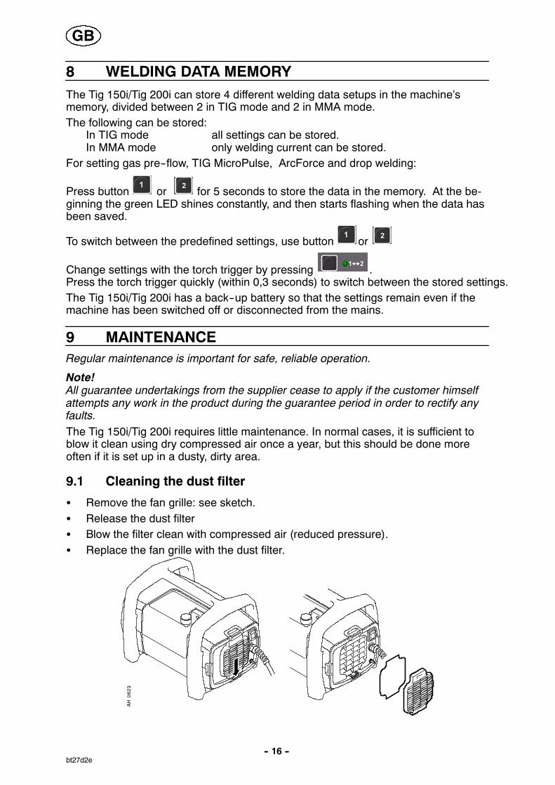
9.1 Cleaning the dust filter
S Remove the fan grille: see sketch.S Release the dust filterS Blow the filter clean with compressed air (reduced pressure).S Replace the fan grille with the dust filter.
GB

-- 17 --bt27d2e
10 FAULT TRACINGTry these recommended checks and inspections before sending for an authorisedservice technician.
Type of fault Action
No arc. S Check that the mains power supply switch is turned on.S Check that the welding current supply and return cables are
correctly connected.S Check that the correct current value is set.
The welding current is interrup-ted during welding.
S Check whether the thermal overload trips have operated(indicated by the yellow lamp on the front panel).
S Check the main power supply fuses.
The thermal overload trip opera-tes frequently.
S Make sure that you are not exceeding the rated data for thewelding power source (i.e. that the unit is not beingoverloaded).
S Check that the dust filter is clean.
Poor welding performance. S Check that the welding current supply and return cables arecorrectly connected.
S Check that the correct current value is set.S Check that the correct electrodes are being used.S Check the main power supply fuses.
10.1 Fault codesThe Tig 150i/Tig 200i comes with built--in fault monitoring. If a fault occurs, a code isshown in the display.
If any of these fault codes is displayed permanently or recurs often, the machineshould be sent to an authorised ESAB service workshop for repair.
Fault Description Resetting Action
E1 Internal RAM fault Restart the machine.If the fault persists, contact aservice workshop
E2 External RAM fault Restart the machine.If the fault persists, contact aservice workshop
E3 EPROM fault Restart the machine.If the fault persists, contact aservice workshop
E4 Fault in RAM with batterybackup
Restart the machine.If the fault persists, contact aservice workshop
E5 Memory error, variable va-lue outside limits
Restart the machine.If the fault persists, contact aservice workshop
E6 Low battery voltage Reset by pressing a button If the fault persists, contact aservice workshop
E10 + 20V fault(18.5 – 21.5 V)
Automatic reset once faulthas disappeared
E11 --15V fault(--13.0 -- --16.0)
Automatic reset once faulthas disappeared
E13 High temperature Automatic reset once faulthas disappeared
GB

-- 18 --bt27d2e
Fault ActionResettingDescription
E14 Current servo fault Automatic reset once faulthas disappeared Also resetby pressing a button
E99 Bridging fault The digital control card isbridged in a non--definedcombination.
Restart the machine.If the fault persists, contact aservice workshop
11 ORDERING SPARE PARTS
Tig 150i / Tig 200i is designed and tested in accordance with the international and Eu-ropean standards IEC/EN 60974--1, 60974--3 and EN 60974--10. It is the obligation of theservice unit which has carried out the service or repair work to make sure that the pro-duct still conforms to the said standard.
Repair and electrical work should be performed by an authorized ESAB serviceman.Use only ESAB original spare and wear parts.
Spare parts may be ordered through your nearest ESAB dealer, see the last page ofthis publication.
GB

-- 19 --p

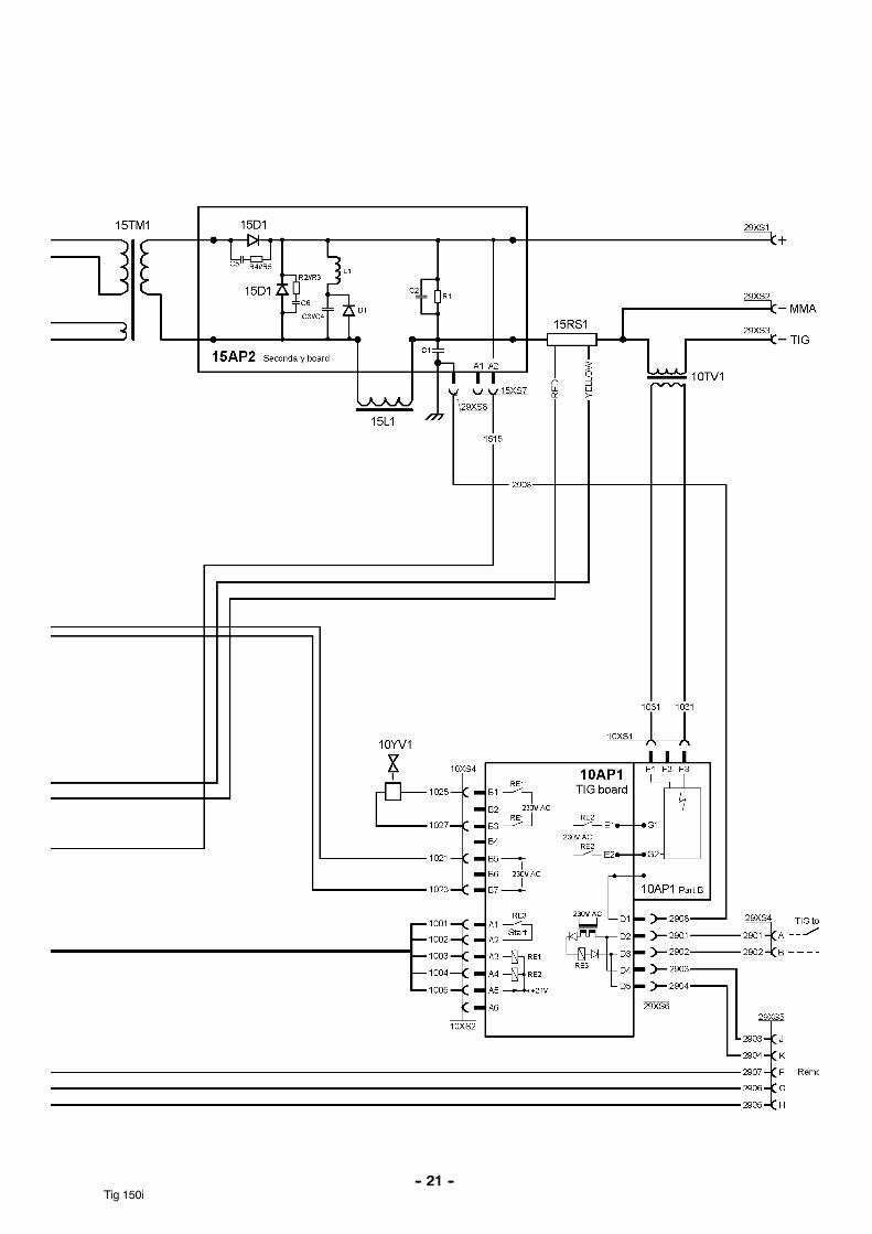
Diagram
-- 20 --Tig 150i
Tig 150i
-- 21 --Tig 150i
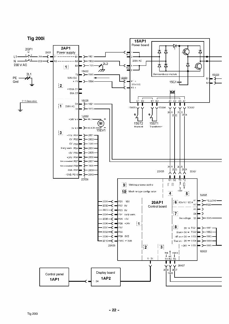
-- 22 --Tig 200i
Tig 200i

-- 23 --Tig 200i

Tig 150i, Tig 200i
Edition 060523
Ordering number
-- 24 --bt27o
Ordering no. Denomination Type Notes
0459 199 881 Welding Power source CaddytTig 150i, TA34 for230 V mains voltage
0459 199 885 Welding Power source CaddytTig 150i, TA34 for230 V mains voltage
Incl welding kit
0459 199 887 Welding Power source CaddytTig 150i, TA34 for230 V mains voltage
CSA version for the NorthAmerican market.Incl welding kit
0459 199 888 Welding Power source CaddytTig 150i, TA34 for230 V mains voltage
CSA version for the NorthAmerican market
0459 199 883 Welding Power source CaddytTig 150i, TA34 for230 V mains voltage
0459 199 889 Welding Power source CaddytTig 150i, TA34 for230 V mains voltage
Incl welding kit
0459 264 990 Spare part list CaddytTig 150i/CaddytTig 200i
English only

Tig 150i, Tig 200i
Edition 060523
Spare parts list
-- 25 --bh26s
Item Qty Ordering no. Denomination
101 1 0459 277 001 Filter

R0459 264 /E060523/P27
Tig 150i, Tig 200i
Accessories
-- 26 --bt27a
MMA welding and return cable kit . . . . . . . .(”crocodile” type holder)
0349 501 078
MMA welding and return cable kit . . . . . . . .(”screwe” type holder)
0349 501 079
Remote control MMA 1 (10 m cable) . . . . . . .
MMA and TIG: current
0349 501 024
Foot control FS002 . . . . . . . . . . . . . . . . . . . . . .
MMA and TIG: current
0349 090 886
Remote control unit AT1 . . . . . . . . . . . . . . . . .
MMA and TIG: current
0459 491 896
Remote control unit AT1 CF . . . . . . . . . . . . .
MMA and TIG: rough and fine setting ofcurrent.
0459 491 897
Remote cable 12 pole -- 8 pole5 m . . . . . . . . . . . . . . . . . . . . . . . . . . . . . . . . . . . . .10 m . . . . . . . . . . . . . . . . . . . . . . . . . . . . . . . . . . . .15 m . . . . . . . . . . . . . . . . . . . . . . . . . . . . . . . . . . . .25 m . . . . . . . . . . . . . . . . . . . . . . . . . . . . . . . . . . . .
0459 552 8800459 552 8810459 552 8820459 552 883
Shoulderstrap . . . . . . . . . . . . . . . . . . . . . . . . . . 0459 367 880

R0459 264 /E060523/P27
Tig 150i, Tig 200i
-- 27 --bt27a
Trolley small gas bottle . . . . . . . . . . . . . . . . . . 0459 366 880
TIG Torch . . . . . . . . . . . . . . . . . . . . . . . . . . . . . . .BTF 150 OKC25
0458 218 890
ESAB ABSE--695 81 LAXÅSWEDENPhone +46 584 81 000
www.esab.com
060517
ESAB subsidiaries and representative offices
EuropeAUSTRIAESAB Ges.m.b.HVienna--LiesingTel: +43 1 888 25 11Fax: +43 1 888 25 11 85
BELGIUMS.A. ESAB N.V.BrusselsTel: +32 2 745 11 00Fax: +32 2 745 11 28
THE CZECH REPUBLICESAB VAMBERK s.r.o.PragueTel: +420 2 819 40 885Fax: +420 2 819 40 120
DENMARKAktieselskabet ESABHerlevTel: +45 36 30 01 11Fax: +45 36 30 40 03
FINLANDESAB OyHelsinkiTel: +358 9 547 761Fax: +358 9 547 77 71
FRANCEESAB France S.A.Cergy PontoiseTel: +33 1 30 75 55 00Fax: +33 1 30 75 55 24
GERMANYESAB GmbHSolingenTel: +49 212 298 0Fax: +49 212 298 218
GREAT BRITAINESAB Group (UK) LtdWaltham CrossTel: +44 1992 76 85 15Fax: +44 1992 71 58 03
ESAB Automation LtdAndoverTel: +44 1264 33 22 33Fax: +44 1264 33 20 74
HUNGARYESAB KftBudapestTel: +36 1 20 44 182Fax: +36 1 20 44 186
ITALYESAB Saldatura S.p.A.Mesero (Mi)Tel: +39 02 97 96 81Fax: +39 02 97 28 91 81
THE NETHERLANDSESAB Nederland B.V.UtrechtTel: +31 30 2485 377Fax: +31 30 2485 260
NORWAYAS ESABLarvikTel: +47 33 12 10 00Fax: +47 33 11 52 03
POLANDESAB Sp.zo.o.KatowiceTel: +48 32 351 11 00Fax: +48 32 351 11 20
PORTUGALESAB LdaLisbonTel: +351 8 310 960Fax: +351 1 859 1277
SLOVAKIAESAB Slovakia s.r.o.BratislavaTel: +421 7 44 88 24 26Fax: +421 7 44 88 87 41
SPAINESAB Ibérica S.A.Alcalá de Henares (MADRID)Tel: +34 91 878 3600Fax: +34 91 802 3461
SWEDENESAB Sverige ABGothenburgTel: +46 31 50 95 00Fax: +46 31 50 92 22
ESAB international ABGothenburgTel: +46 31 50 90 00Fax: +46 31 50 93 60
SWITZERLANDESAB AGDietikonTel: +41 1 741 25 25Fax: +41 1 740 30 55
North and South AmericaARGENTINACONARCOBuenos AiresTel: +54 11 4 753 4039Fax: +54 11 4 753 6313
BRAZILESAB S.A.Contagem--MGTel: +55 31 2191 4333Fax: +55 31 2191 4440
CANADAESAB Group Canada Inc.Missisauga, OntarioTel: +1 905 670 02 20Fax: +1 905 670 48 79
MEXICOESAB Mexico S.A.MonterreyTel: +52 8 350 5959Fax: +52 8 350 7554
USAESAB Welding & Cutting ProductsFlorence, SCTel: +1 843 669 44 11Fax: +1 843 664 57 48
Asia/PacificCHINAShanghai ESAB A/PShanghaiTel: +86 21 5308 9922Fax: +86 21 6566 6622
INDIAESAB India LtdCalcuttaTel: +91 33 478 45 17Fax: +91 33 468 18 80
INDONESIAP.T. ESABindo PratamaJakartaTel: +62 21 460 0188Fax: +62 21 461 2929
JAPANESAB JapanTokyoTel: +81 3 5296 7371Fax: +81 3 5296 8080
MALAYSIAESAB (Malaysia) Snd BhdSelangorTel: +60 3 8027 9869Fax: +60 3 8027 4754
SINGAPOREESAB Asia/Pacific Pte LtdSingaporeTel: +65 6861 43 22Fax: +65 6861 31 95
SOUTH KOREAESAB SeAH CorporationKyungnamTel: +82 55 269 8170Fax: +82 55 289 8864
UNITED ARAB EMIRATESESAB Middle East FZEDubaiTel: +971 4 887 21 11Fax: +971 4 887 22 63
Representative officesBULGARIAESAB Representative OfficeSofiaTel/Fax: +359 2 974 42 88
EGYPTESAB EgyptDokki--CairoTel: +20 2 390 96 69Fax: +20 2 393 32 13
ROMANIAESAB Representative OfficeBucharestTel/Fax: +40 1 322 36 74
RUSSIALLC ESABMoscowTel: +7 095 543 9281Fax: +7 095 543 9280
LLC ESABSt PetersburgTel: +7 812 336 7080Fax: +7 812 336 7060
DistributorsFor addresses and phonenumbers to our distributors inother countries, please visit ourhome page
www.esab.com