TIENet 350 Area Velocity Sensor - Teledyne ISCO · Section 3 Setup and Programming ... 2-8 Attach...
50
TIENet™ 350 Area Velocity Sensor Installation and Operation Guide Manual Body #69-4353-024 Copyright © 2012. All rights reserved, Teledyne Isco Revision D, January 2016
Transcript of TIENet 350 Area Velocity Sensor - Teledyne ISCO · Section 3 Setup and Programming ... 2-8 Attach...

TIENet™ 350Area Velocity Sensor
Installation and Operation Guide
Manual Body #69-4353-024Copyright © 2012. All rights reserved, Teledyne IscoRevision D, January 2016

Foreword
This instruction manual is designed to help you gain a thorough understanding of the operation ofthe equipment. Teledyne Isco recommends that you read this manual completely before placing theequipment in service.
Although Teledyne Isco designs reliability into all equipment, there is always the possibility of amalfunction. This manual may help in diagnosing and repairing the malfunction.
If a problem persists, call or e-mail Teledyne Isco technical support for assistance. Simpledifficulties can often be diagnosed over the phone. For faster service, please have your serialnumber ready.
If it is necessary to return the equipment to the factory for service, please follow the shippinginstructions provided by technical support, including the use of the Return MerchandiseAuthorization (RMA) specified. Be sure to include a note describing the malfunction. This willaid in the prompt repair and return of the equipment.
Teledyne Isco welcomes suggestions that would improve the information presented in this manualor enhance the operation of the equipment itself.
Teledyne Isco is continually improving its products and reserves the right to change productspecifications, replacement parts, schematics, and instructions without notice.
Contact Information
Customer Service
Phone: (800) 228-4373 (USA, Canada, Mexico)
(402) 464-0231 (Outside North America)
Fax: (402) 465-3022
Email: [email protected]
Technical Support
Phone: Toll Free (866) 298-6174 (Samplers, Flow Meters and Multi-parameter Probes)
Toll Free (800) 775-2965 (Syringe Pumps and Liquid Chromatography)
Email: [email protected] [email protected]
Return equipment to: 4700 Superior Street, Lincoln, NE 68504-1398
Other Correspondence
Mail to: P.O. Box 82531, Lincoln, NE 68501-2531
Email: [email protected]

TIENet™ 350 Area Velocity SensorSafety
v
TIENet™ 350 Area Velocity SensorSafety
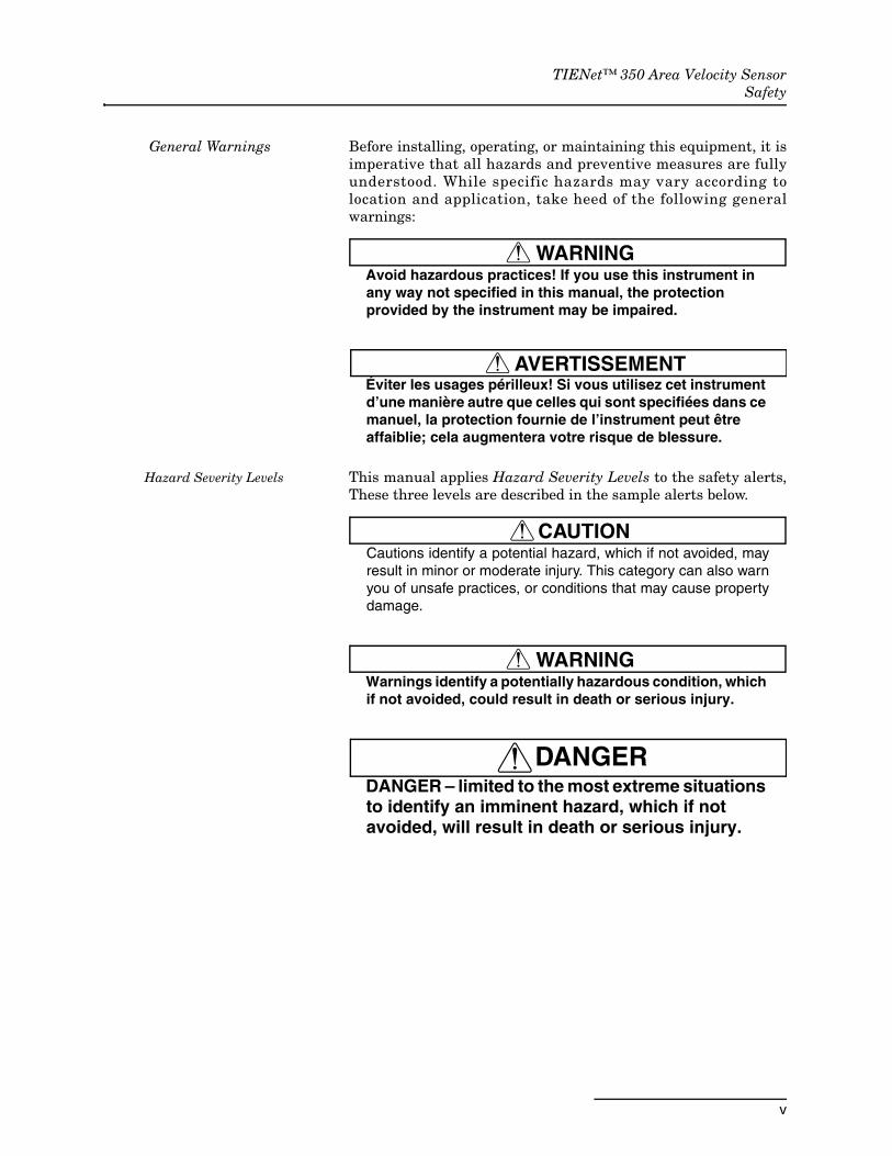
General Warnings Before installing, operating, or maintaining this equipment, it isimperative that all hazards and preventive measures are fullyunderstood. While specific hazards may vary according tolocation and application, take heed of the following generalwarnings:
WARNINGAvoid hazardous practices! If you use this instrument in any way not specified in this manual, the protection provided by the instrument may be impaired.
AVERTISSEMENTÉviter les usages périlleux! Si vous utilisez cet instrument d’une manière autre que celles qui sont specifiées dans ce manuel, la protection fournie de l’instrument peut être affaiblie; cela augmentera votre risque de blessure.
Hazard Severity Levels This manual applies Hazard Severity Levels to the safety alerts,These three levels are described in the sample alerts below.
CAUTIONCautions identify a potential hazard, which if not avoided, mayresult in minor or moderate injury. This category can also warnyou of unsafe practices, or conditions that may cause propertydamage.
WARNINGWarnings identify a potentially hazardous condition, which if not avoided, could result in death or serious injury.
DANGERDANGER – limited to the most extreme situations to identify an imminent hazard, which if not avoided, will result in death or serious injury.
TIENet™ 350 Area Velocity SensorSafety
vi
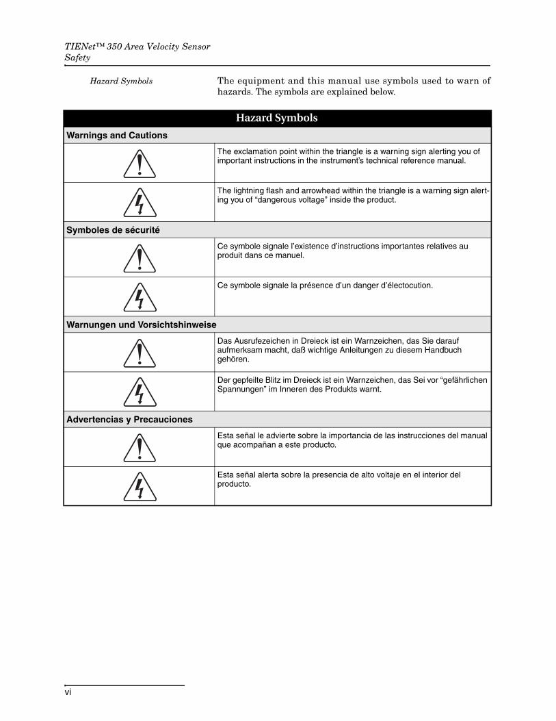
Hazard Symbols The equipment and this manual use symbols used to warn ofhazards. The symbols are explained below.
Hazard Symbols
Warnings and Cautions
The exclamation point within the triangle is a warning sign alerting you of important instructions in the instrument’s technical reference manual.
The lightning flash and arrowhead within the triangle is a warning sign alert-ing you of “dangerous voltage” inside the product.
Symboles de sécurité
Ce symbole signale l’existence d’instructions importantes relatives au produit dans ce manuel.
Ce symbole signale la présence d’un danger d’électocution.
Warnungen und Vorsichtshinweise
Das Ausrufezeichen in Dreieck ist ein Warnzeichen, das Sie darauf aufmerksam macht, daß wichtige Anleitungen zu diesem Handbuch gehören.
Der gepfeilte Blitz im Dreieck ist ein Warnzeichen, das Sei vor “gefährlichen Spannungen” im Inneren des Produkts warnt.
Advertencias y Precauciones
Esta señal le advierte sobre la importancia de las instrucciones del manual que acompañan a este producto.
Esta señal alerta sobre la presencia de alto voltaje en el interior del producto.

vii
TIENet™ Model 350 Area Velocity Sensor
Table of Contents
Section 1 Introduction
1.1 Description. . . . . . . . . . . . . . . . . . . . . . . . . . . . . . . . . . . . . . . . . . . . . . . . . . . . . . . . . 1-11.1.1 350 Velocity Operation . . . . . . . . . . . . . . . . . . . . . . . . . . . . . . . . . . . . . . . . . 1-21.1.2 350 Level Operation . . . . . . . . . . . . . . . . . . . . . . . . . . . . . . . . . . . . . . . . . . . 1-2
1.2 Technical Specifications . . . . . . . . . . . . . . . . . . . . . . . . . . . . . . . . . . . . . . . . . . . . . . 1-31.3 Optional LaserFlow Applications . . . . . . . . . . . . . . . . . . . . . . . . . . . . . . . . . . . . . . . 1-41.4 Accessories . . . . . . . . . . . . . . . . . . . . . . . . . . . . . . . . . . . . . . . . . . . . . . . . . . . . . . . . . 1-4
1.4.1 Ordering Information . . . . . . . . . . . . . . . . . . . . . . . . . . . . . . . . . . . . . . . . . . 1-51.5 Unpacking Instructions . . . . . . . . . . . . . . . . . . . . . . . . . . . . . . . . . . . . . . . . . . . . . . 1-5
Section 2 Installation
2.1 Safety . . . . . . . . . . . . . . . . . . . . . . . . . . . . . . . . . . . . . . . . . . . . . . . . . . . . . . . . . . . . . 2-12.1.1 Site Conditions . . . . . . . . . . . . . . . . . . . . . . . . . . . . . . . . . . . . . . . . . . . . . . . . 2-1
2.2 Reference Line Support. . . . . . . . . . . . . . . . . . . . . . . . . . . . . . . . . . . . . . . . . . . . . . . 2-22.3 Preparing the Signature Flow Meter . . . . . . . . . . . . . . . . . . . . . . . . . . . . . . . . . . . . 2-3
2.3.1 External Desiccator . . . . . . . . . . . . . . . . . . . . . . . . . . . . . . . . . . . . . . . . . . . . 2-32.4 Connecting the Cable . . . . . . . . . . . . . . . . . . . . . . . . . . . . . . . . . . . . . . . . . . . . . . . . 2-52.5 Installing the 350 AV Sensor . . . . . . . . . . . . . . . . . . . . . . . . . . . . . . . . . . . . . . . . . . 2-9
2.5.1 Installation Considerations . . . . . . . . . . . . . . . . . . . . . . . . . . . . . . . . . . . . . . 2-92.5.2 Mounting Rings . . . . . . . . . . . . . . . . . . . . . . . . . . . . . . . . . . . . . . . . . . . . . . 2-102.5.3 Spring Rings . . . . . . . . . . . . . . . . . . . . . . . . . . . . . . . . . . . . . . . . . . . . . . . . . 2-102.5.4 Scissors Mounting Ring . . . . . . . . . . . . . . . . . . . . . . . . . . . . . . . . . . . . . . . . 2-122.5.5 Completing the Sensor Installation . . . . . . . . . . . . . . . . . . . . . . . . . . . . . . 2-14
2.6 Street Level Installation System . . . . . . . . . . . . . . . . . . . . . . . . . . . . . . . . . . . . . . 2-142.7 Grounding Kit for Surge Protection . . . . . . . . . . . . . . . . . . . . . . . . . . . . . . . . . . . . 2-14
Section 3 Setup and Programming
3.1 Configuring the System . . . . . . . . . . . . . . . . . . . . . . . . . . . . . . . . . . . . . . . . . . . . . . 3-13.1.1 Updating the Device List . . . . . . . . . . . . . . . . . . . . . . . . . . . . . . . . . . . . . . . . 3-1
3.2 Measurement Setup . . . . . . . . . . . . . . . . . . . . . . . . . . . . . . . . . . . . . . . . . . . . . . . . . 3-43.2.1 350 Velocity . . . . . . . . . . . . . . . . . . . . . . . . . . . . . . . . . . . . . . . . . . . . . . . . . . 3-43.2.2 Advanced Settings . . . . . . . . . . . . . . . . . . . . . . . . . . . . . . . . . . . . . . . . . . . . . 3-53.2.3 Setting the 350 Level . . . . . . . . . . . . . . . . . . . . . . . . . . . . . . . . . . . . . . . . . . . 3-6
Section 4 Maintenance
4.1 Maintenance . . . . . . . . . . . . . . . . . . . . . . . . . . . . . . . . . . . . . . . . . . . . . . . . . . . . . . . 4-14.2 Firmware Updates . . . . . . . . . . . . . . . . . . . . . . . . . . . . . . . . . . . . . . . . . . . . . . . . . . 4-14.3 External Desiccator. . . . . . . . . . . . . . . . . . . . . . . . . . . . . . . . . . . . . . . . . . . . . . . . . . 4-24.4 In Pipe or Channel Sensor Cleaning . . . . . . . . . . . . . . . . . . . . . . . . . . . . . . . . . . . . 4-34.5 Cleaning. . . . . . . . . . . . . . . . . . . . . . . . . . . . . . . . . . . . . . . . . . . . . . . . . . . . . . . . . . . 4-34.6 Contact Teledyne Isco . . . . . . . . . . . . . . . . . . . . . . . . . . . . . . . . . . . . . . . . . . . . . . . . 4-4
TIENet™ Model 350 Area Velocity SensorTable of Contents
viii
Appendix A Replacement Parts List
A.1 Replacement Parts Diagrams and Listings . . . . . . . . . . . . . . . . . . . . . . . . . . . . . . A-1
Appendix B Velocity Error Codes
B.1 Introduction . . . . . . . . . . . . . . . . . . . . . . . . . . . . . . . . . . . . . . . . . . . . . . . . . . . . . . . B-1B.2 Importing Data Dump (.ddp) Files . . . . . . . . . . . . . . . . . . . . . . . . . . . . . . . . . . . . . B-1B.3 Viewing Velocity Error Codes in Flowlink . . . . . . . . . . . . . . . . . . . . . . . . . . . . . . . B-3
List of Figures1-1 Basic Signature monitoring system with 350 (mounting hardware not shown) . 1-11-2 TIENet Model 350 Area Velocity Sensor . . . . . . . . . . . . . . . . . . . . . . . . . . . . . . . . 1-22-1 Remove red caps before installing external desiccant cartridge . . . . . . . . . . . . . . 2-32-2 Installing the external desiccant cartridge . . . . . . . . . . . . . . . . . . . . . . . . . . . . . . . 2-32-3 External desiccator, installed . . . . . . . . . . . . . . . . . . . . . . . . . . . . . . . . . . . . . . . . . 2-42-4 Tubing configuration for optimal drying power . . . . . . . . . . . . . . . . . . . . . . . . . . . 2-52-5 TIENet Device terminal strips . . . . . . . . . . . . . . . . . . . . . . . . . . . . . . . . . . . . . . . . 2-62-6 Installing cable with a cord-grip fitting . . . . . . . . . . . . . . . . . . . . . . . . . . . . . . . . . 2-62-7 TIENet Device terminal connections . . . . . . . . . . . . . . . . . . . . . . . . . . . . . . . . . . . 2-72-8 Attach wired terminal strip to case board socket . . . . . . . . . . . . . . . . . . . . . . . . . . 2-72-9 Insert the cable reference tubing into the case board reference port . . . . . . . . . . 2-82-10 Position and secure the cable . . . . . . . . . . . . . . . . . . . . . . . . . . . . . . . . . . . . . . . . . 2-82-11 Sensor Installed on a Spring Ring . . . . . . . . . . . . . . . . . . . . . . . . . . . . . . . . . . . 2-112-12 Scissors Ring adjustment . . . . . . . . . . . . . . . . . . . . . . . . . . . . . . . . . . . . . . . . . . . 2-133-1 Character grid . . . . . . . . . . . . . . . . . . . . . . . . . . . . . . . . . . . . . . . . . . . . . . . . . . . . . 3-23-2 Menu Tree: 350 Configuration . . . . . . . . . . . . . . . . . . . . . . . . . . . . . . . . . . . . . . . . . 3-33-3 Configuring level and velocity measurement . . . . . . . . . . . . . . . . . . . . . . . . . . . . . 3-43-4 Measurement setup: Advanced settings for 350 AV sensor . . . . . . . . . . . . . . . . . . 3-53-5 350 Level adjustment screen . . . . . . . . . . . . . . . . . . . . . . . . . . . . . . . . . . . . . . . . . . 3-64-1 Desiccant indicating saturation . . . . . . . . . . . . . . . . . . . . . . . . . . . . . . . . . . . . . . . . 4-24-2 Removing the external desiccant cartridge . . . . . . . . . . . . . . . . . . . . . . . . . . . . . . 4-24-3 Opening the desiccant cartridge chambers . . . . . . . . . . . . . . . . . . . . . . . . . . . . . . . 4-3B-1 Signature flow data: Selecting the .ddp file(s) . . . . . . . . . . . . . . . . . . . . . . . . . . . . B-1B-2 Signature flow data: Importing the .ddp file . . . . . . . . . . . . . . . . . . . . . . . . . . . . . B-2B-3 Identifying error codes in the 360 Velocity data set . . . . . . . . . . . . . . . . . . . . . . . B-3

1-1
TIENet™ Model 350 Area Velocity Sensor
Section 1 Introduction
The Teledyne Isco TIENet 350 Area Velocity Sensor measuresflow stream average area velocity and liquid level. The Sig-nature® Flow Meter uses this information to calculate the flowrate and total flow of the stream. To operate with the 350 sensor,the Signature requires software version 1.18 or later.
1.1 Description The 350 sensor is mounted in the flow stream, normally at thebottom of the channel. It measures average velocity using con-tinuous ultrasonic sound waves to produce a Doppler effect, inwhich the frequency of a wave (such as sound) passed betweentwo bodies is relative to the motion of each. As they move nearerto each other, the frequency increases; as they move apart, thefrequency decreases.
The 350 sensor measures liquid level using an internal differ-ential pressure transducer.
Figure 1-1 Basic Signature monitoring system with 350 (mounting hardware not shown)
Signature Flow Meter
TIENet 350 AV Sensor

TIENet™ Model 350 Area Velocity SensorSection 1 Introduction
1-2
The 350 AV sensor is available with a 5m, 10m, or 23m cable. Forgreater distances, external connection via conduit, and con-nection of additional TIENet devices, the TIENet Expansion Boxis available. Bulk TIENet cable may also be used for greater dis-tances.
Figure 1-2 TIENet Model 350 Area Velocity Sensor
1.1.1 350 Velocity Operation The 350 area velocity sensor contains a pair of ultrasonic trans-ducers. One transducer transmits the ultrasonic sound wave. Asthe transmitted wave travels through the stream, particles andbubbles carried by the stream reflect the sound wave back at thesensor. The second transducer receives the reflected wave.
The sensor determines the frequency shift between the trans-mitted and received waves. An increase or decrease in the fre-quency of the reflected wave indicates forward or reverse flow.The degree of change is proportional to the velocity of the flowstream.
1.1.2 350 Level Operation The 350 sensor’s internal differential pressure transducer mea-sures the liquid level. The transducer is a small piezo-resistivechip that detects the difference of the pressures felt on the innerand outer face.
The stainless steel outer diaphragm is exposed to the flow streamthrough the ports under the sensor. The pressure felt on theouter diaphragm is transferred to the outer face of the trans-ducer. The inner face of the transducer is referenced to the atmo-sphere through the internal vent tube that runs the full length ofthe sensor cable.
The difference between the pressures exerted on the transduceris the hydrostatic pressure, which is proportional to the level ofthe stream. The analog representation of the hydrostaticpressure is digitized and sent to the Signature as an RS-485half-duplex signal.
Particles or air bubbles
Ultrasonicsound waves
Flow

TIENet™ Model 350 Area Velocity SensorSection 1 Introduction
1-3
1.2 Technical Specifications
Table 1-1 350 TIENet Sensor Specificationsa
Sensor Dimensions 1.9 3.3 15.2 cm 0.75 1.31 6.00 in
Standard Cable Length 5, 10, or 23 m 16.4, 32.8, or 75.5 ft
Cable Diameter 10.2mm ±0.254mm 0.402 in ±0.010 in
Minimum Bend Radius 15.24 cm 6 in
Maximum Cabling from Signature Flow Meter 305 m 1,000 ft
Typical Weightw/ 5 m Cablew/ 10 m Cablew/ 23 m Cable
0.88 kg 1.95 lb1.68 kg 3.70 lb3.10 kg 6.84lb
Body Materials Epoxy, PC, SST
Cable Materials UV-Rated PVC
Temperature RangeOperationStorage
0 to 70 °C 32 to 158 °F-40 to 70 °C -40 to 158 °F
Power InputVoltageSupply Current @ 12VDC Nominal
7 to 14VDCMeasurement: 100mA
Level Measurement
Technology Submerged differential linear pressure transducer with integral digital temperature compensation coefficients.
Rangeb 0.010 to 3.05 m 0.033 to 10 ft.
Pressure Rating 5 PSI
Maximum Submersible Depth 10.55 m 34.6 ft
Accuracyc ± 0.10% FS
Typical Long Term Stability ± 0.007m/yr ± 0.023 ft/yr
Compensated Temperature Range 0 to 70°C 32 to 158°F
Velocity Measurement
Technology Continuous wave Doppler ultrasonic
Frequency 500 kHz
Transmission Angle 20° from horizontal
Velocity Direction Bi-Directional (User selectable)
Typical Minimum Depth for Velocity Measurement 2.5 cm 1.0 in
Range -1.5 to +6.1 m/s -5 to +20 ft./s
Accuracyd Velocity Error
-5 to +5 ft./s: -1.5 to +1.5 m/s ±0.1 ft./s (±0.03 m/s)5 to 20 ft./s: 1.5 to 6.1 m/s ±2% of reading
a. All specifications are subject to change without notice.
b. Actual vertical distance between the area velocity sensor and the liquid surfacec. Maximum non-linearity, hysteresis, and temperature error from actual liquid leveld. Uniform velocity profile, speed of sound 1480 m/s (4850 ft/s)
TIENet™ Model 350 Area Velocity SensorSection 1 Introduction
1-4
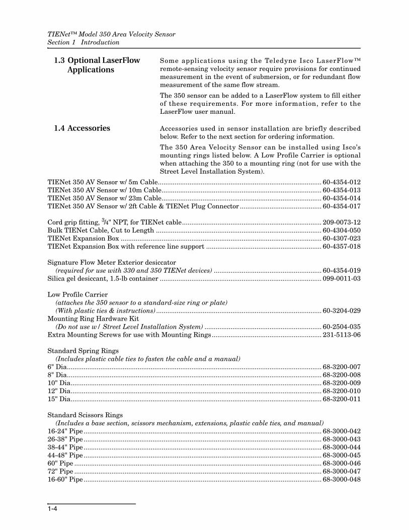
1.3 Optional LaserFlow Applications
Some applications using the Teledyne Isco LaserFlow™remote-sensing velocity sensor require provisions for continuedmeasurement in the event of submersion, or for redundant flowmeasurement of the same flow stream.
The 350 sensor can be added to a LaserFlow system to fill eitherof these requirements. For more information, refer to theLaserFlow user manual.
1.4 Accessories Accessories used in sensor installation are briefly describedbelow. Refer to the next section for ordering information.
The 350 Area Velocity Sensor can be installed using Isco’smounting rings listed below. A Low Profile Carrier is optionalwhen attaching the 350 to a mounting ring (not for use with theStreet Level Installation System).
TIENet 350 AV Sensor w/ 5m Cable........................................................................................ 60-4354-012TIENet 350 AV Sensor w/ 10m Cable...................................................................................... 60-4354-013TIENet 350 AV Sensor w/ 23m Cable...................................................................................... 60-4354-014TIENet 350 AV Sensor w/ 2ft Cable & TIENet Plug Connector ............................................ 60-4354-017
Cord grip fitting, 3/4" NPT, for TIENet cable........................................................................... 209-0073-12Bulk TIENet Cable, Cut to Length ......................................................................................... 60-4304-050TIENet Expansion Box ............................................................................................................ 60-4307-023TIENet Expansion Box with reference line support .............................................................. 60-4357-018
Signature Flow Meter Exterior desiccator(required for use with 330 and 350 TIENet devices) .......................................................... 60-4354-019
Silica gel desiccant, 1.5-lb container ....................................................................................... 099-0011-03
Low Profile Carrier(attaches the 350 sensor to a standard-size ring or plate)(With plastic ties & instructions) ......................................................................................... 60-3204-029
Mounting Ring Hardware Kit(Do not use w/ Street Level Installation System) ............................................................... 60-2504-035
Extra Mounting Screws for use with Mounting Rings........................................................... 231-5113-06
Standard Spring Rings(Includes plastic cable ties to fasten the cable and a manual)
6" Dia......................................................................................................................................... 68-3200-0078" Dia......................................................................................................................................... 68-3200-00810" Dia....................................................................................................................................... 68-3200-00912" Dia....................................................................................................................................... 68-3200-01015" Dia....................................................................................................................................... 68-3200-011
Standard Scissors Rings(Includes a base section, scissors mechanism, extensions, plastic cable ties, and manual)
16-24" Pipe ................................................................................................................................ 68-3000-04226-38" Pipe ................................................................................................................................ 68-3000-04338-44" Pipe ................................................................................................................................ 68-3000-04444-48" Pipe ................................................................................................................................ 68-3000-04560" Pipe ..................................................................................................................................... 68-3000-04672" Pipe ..................................................................................................................................... 68-3000-04716-60" Pipe ................................................................................................................................ 68-3000-048

TIENet™ Model 350 Area Velocity SensorSection 1 Introduction
1-5
Base Section (with plastic cable ties and manual) ................................................................. 60-3004-169Street Level Installation System Multi-section Pole (Includes manual. To complete your system, you
must also order a Street Level Mounting Ring) .................................................................. 60-3204-012Street Level Mounting Ring for 6" dia. pipe ........................................................................... 60-3204-014Street Level Mounting Ring for 8" dia. pipe ........................................................................... 60-3204-015Street Level Mounting Ring for 10" dia. pipe ......................................................................... 60-3204-016Street Level Mounting Ring for 12" dia. pipe ......................................................................... 60-3204-017Street Level Mounting Ring for 15" dia. pipe ......................................................................... 60-3204-018
Sensor Mounting Plate............................................................................................................. 60-3253-077Ground Lug kit ......................................................................................................................... 60-2007-476
1.4.1 Ordering Information Options and accessories can be purchased by contacting TeledyneIsco’s Customer Service Department.
Teledyne IscoCustomer Service Dept.P.O. Box 82531Lincoln, NE 68501 USA
Phone: 800 228-4373402 464-0231
FAX: 402 465-3022
E-mail:[email protected]
NoteTeledyne Isco uses FreeRTOS version 5.4.2 in its TIENetdevices. In accordance with the FreeRTOS license, FreeRTOSsource code is available on request. For more information, visitwww.FreeRTOS.org.
1.5 Unpacking Instructions
When the system arrives, inspect the outside packing for anydamage. Then carefully inspect the contents for damage. If thereis damage, contact the delivery company and Teledyne Isco (or itsagent) immediately.
WARNINGIf there is any evidence that any items may have been damaged in shipping, do not attempt to install the unit. Please contact Teledyne Isco (or its agent) for assistance.
When you unpack the system, check the items against thepacking list. If any parts are missing, contact the deliverycompany and Teledyne Isco’s Customer Service Department.When you report missing part(s), please indicate them by partnumber. In addition to the main packing list, there may be otherpacking lists for various sub-components.
It is recommended that you retain the shipping cartons as theycan be used to ship the unit in the event that it is necessary totransport the system.

TIENet™ Model 350 Area Velocity SensorSection 1 Introduction
1-6
Please complete the registration card and return it to TeledyneIsco.
2-1
TIENet™ Model 350 Area Velocity Sensor
Section 2 Installation
The Signature Flow Meter does not have to be mounted near theflow stream. You can install the flow meter itself at a convenient,protected location and route the sensor cable to the measurementpoint (maximum length of 305 meters or 1,000 feet). Properinstallation of the 350 sensor is critical for accurate mea-surement.
2.1 Safety Before installing, operating, or maintaining this equipment, it isimperative that all hazards and preventive measures are fullyunderstood.
2.1.1 Site Conditions Components are often installed in confined spaces. Someexamples of confined spaces include manholes, pipelines,digesters, and storage tanks. These spaces may become haz-ardous environments that can prove fatal for those unprepared.These spaces are governed by OSHA 1910.146 and require apermit before entering.
WARNINGThe installation and use of this product may subject you to hazardous working conditions that can cause you serious or fatal injuries. Take any necessary precautions before entering a worksite. Install and operate this product in accordance with all applicable safety and health regulations, and local ordinances.
TIENet™ Model 350 Area Velocity SensorSection 2 Installation
2-2
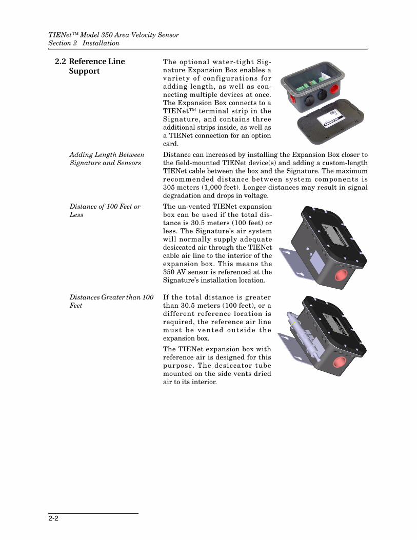
2.2 Reference Line Support
The optional water-tight Sig-nature Expansion Box enables avariety of configurations foradding length, as well as con-necting multiple devices at once.The Expansion Box connects to aTIENet™ terminal strip in theSignature, and contains threeadditional strips inside, as well asa TIENet connection for an optioncard.
Adding Length BetweenSignature and Sensors
Distance can increased by installing the Expansion Box closer tothe field-mounted TIENet device(s) and adding a custom-lengthTIENet cable between the box and the Signature. The maximumrecommended distance between system components is305 meters (1,000 feet). Longer distances may result in signaldegradation and drops in voltage.
Distance of 100 Feet or Less
The un-vented TIENet expansionbox can be used if the total dis-tance is 30.5 meters (100 feet) orless. The Signature’s air systemwill normally supply adequatedesiccated air through the TIENetcable air line to the interior of theexpansion box. This means the350 AV sensor is referenced at theSignature’s installation location.
Distances Greater than 100 Feet
If the total distance is greaterthan 30.5 meters (100 feet), or adifferent reference location isrequired, the reference air linemust be vented outs ide theexpansion box.
The TIENet expansion box withreference air is designed for thispurpose. The desiccator tubemounted on the side vents driedair to its interior.
TIENet™ Model 350 Area Velocity SensorSection 2 Installation
2-3
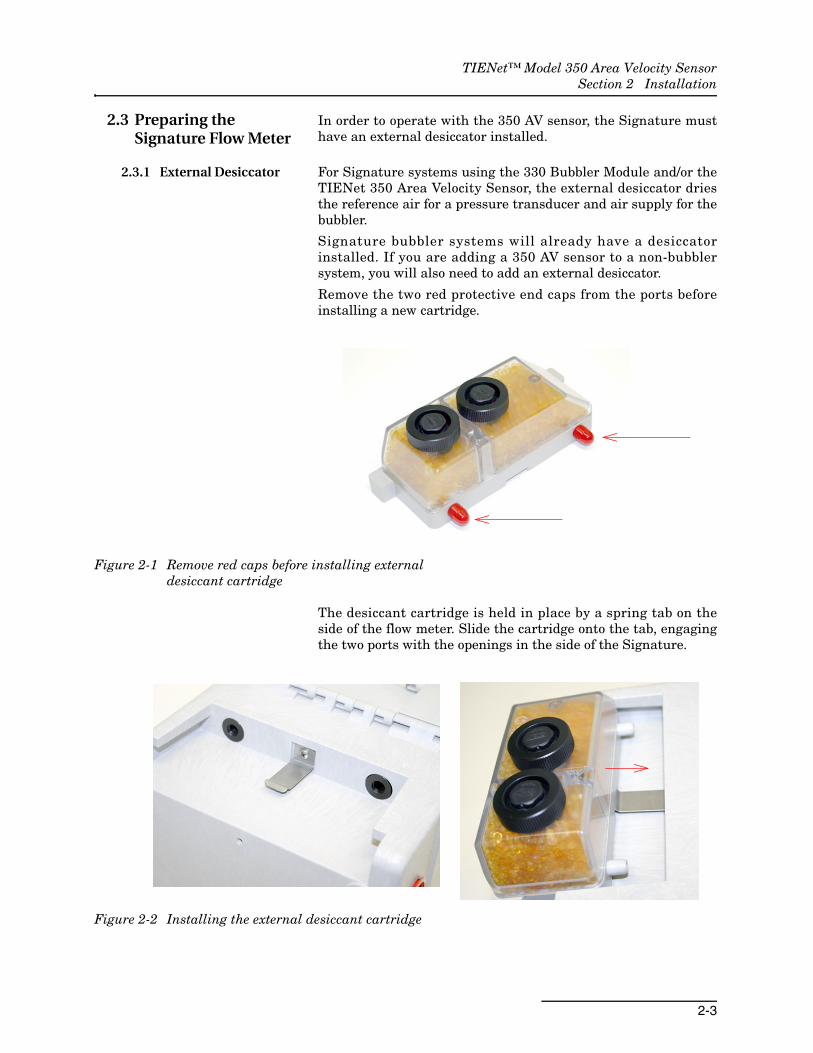
2.3 Preparing the Signature Flow Meter
In order to operate with the 350 AV sensor, the Signature musthave an external desiccator installed.
2.3.1 External Desiccator For Signature systems using the 330 Bubbler Module and/or theTIENet 350 Area Velocity Sensor, the external desiccator driesthe reference air for a pressure transducer and air supply for thebubbler.
Signature bubbler systems will already have a desiccatorinstalled. If you are adding a 350 AV sensor to a non-bubblersystem, you will also need to add an external desiccator.
Remove the two red protective end caps from the ports beforeinstalling a new cartridge.
Figure 2-1 Remove red caps before installing external desiccant cartridge
The desiccant cartridge is held in place by a spring tab on theside of the flow meter. Slide the cartridge onto the tab, engagingthe two ports with the openings in the side of the Signature.
Figure 2-2 Installing the external desiccant cartridge

TIENet™ Model 350 Area Velocity SensorSection 2 Installation
2-4
Figure 2-3 External desiccator, installed
The desiccant cartridge requires periodic maintenance. Refer toSection 4.3 External Desiccator for instructions.
Optimizing drying power Some Signature flow meters have a single piece of tubinginstalled between the reference port and the humidity connector,and a cap plug on the intake port. While a Signature with thistubing configuration will operate satisfactorily with the 350 AVsensor in most situations, you can configure the tubing to utilizeboth chambers of the external desiccator to increase dryingpower.
Items required:
• Plastic ‘Y’ Fitting (Part #209-0167-49)
• 0.25 x 0.125 silicone tubing (Part #029-1353-02: Two 2-inch pieces)
Procedure:
1. Remove the cap plug.
2. Disconnect the tubing from the humidity connector and reroute it behind the ribbon cable.
3. Connect both the reference port tubing and the intake port tubing to the ‘Y’ connector.
4. Connect the ‘Y’ connector to the humidity connector (Figure 2-4).
To air intake
To reference port

TIENet™ Model 350 Area Velocity SensorSection 2 Installation
2-5
Figure 2-4 Tubing configuration for optimal drying power
2.4 Connecting the Cable External TIENet devices such as the 350 are all electrically con-nected to the Signature flow meter in the same manner, usuallyusing conduit or cord-grip cable fittings. Multiple externalTIENet devices can be connected simultaneously.
Refer to your Signature flow meter manual for instructions onaccessing the instrument’s interior components.
WARNINGBefore proceeding, ensure that the flow meter has been disconnected from mains power.
NoteThe steps that follow include instructions for installing cord-gripfittings. Some applications will use user-supplied 3/4" ID con-duit for cable routing.
CAUTIONIf you are using conduit instead of the cord-grip fitting, the con-duit must be sealed to prevent harmful gases and moisturefrom entering the Signature enclosure. Failure to seal conduitcould reduce equipment life.
Reference port tubing
Intake porttubing
Humidity connectortubing

TIENet™ Model 350 Area Velocity SensorSection 2 Installation
2-6
1. Remove one of the 6-position plug-in terminal strip connec-tors from the case board.
Figure 2-5 TIENet Device terminal strips
2. If using a cord-grip fitting, install the cable nut in the appropriate opening on the bottom of the Signature enclo-sure, securing it to the wall with the lock nut (concave side facing wall).
3. Feed the TIENet device cable end through the sealing nut and seal, and through the cable nut. Lightly tighten the sealing nut, just enough to hold the cable in place while installing the connector.
Figure 2-6 Installing cable with a cord-grip fitting
4. Attach the wire ends to the terminal strip as shown in Figure 2-7, then press the terminal strip back down into its socket on the case board, as shown in Figure 2-8, taking
Lock Nut(concave side facing wall)
Cable NutSeal
(color may vary)
Sealing Nut
TIENet™ Model 350 Area Velocity SensorSection 2 Installation
2-7
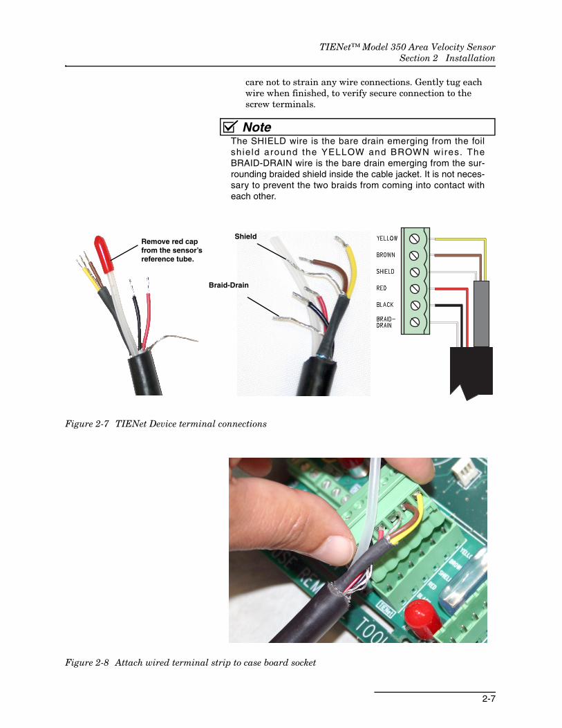
care not to strain any wire connections. Gently tug each wire when finished, to verify secure connection to the screw terminals.
NoteThe SHIELD wire is the bare drain emerging from the foilshie ld around the YELLOW and BROWN wires. TheBRAID-DRAIN wire is the bare drain emerging from the sur-rounding braided shield inside the cable jacket. It is not neces-sary to prevent the two braids from coming into contact witheach other.
Figure 2-7 TIENet Device terminal connections
Figure 2-8 Attach wired terminal strip to case board socket
Braid-Drain
ShieldRemove red capfrom the sensor’sreference tube.
TIENet™ Model 350 Area Velocity SensorSection 2 Installation
2-8
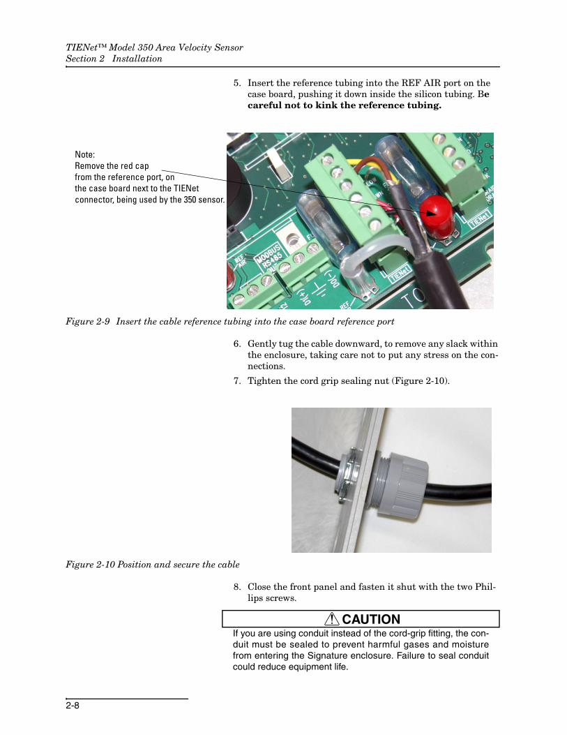
5. Insert the reference tubing into the REF AIR port on the case board, pushing it down inside the silicon tubing. Be careful not to kink the reference tubing.
Figure 2-9 Insert the cable reference tubing into the case board reference port
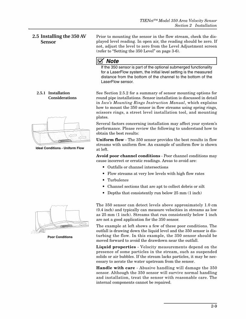
6. Gently tug the cable downward, to remove any slack within the enclosure, taking care not to put any stress on the con-nections.
7. Tighten the cord grip sealing nut (Figure 2-10).
Figure 2-10 Position and secure the cable
8. Close the front panel and fasten it shut with the two Phil-lips screws.
CAUTIONIf you are using conduit instead of the cord-grip fitting, the con-duit must be sealed to prevent harmful gases and moisturefrom entering the Signature enclosure. Failure to seal conduitcould reduce equipment life.
Note:Remove the red capfrom the reference port, onthe case board next to the TIENetconnector, being used by the 350 sensor.
TIENet™ Model 350 Area Velocity SensorSection 2 Installation
2-9
2.5 Installing the 350 AV Sensor
Prior to mounting the sensor in the flow stream, check the dis-played level reading. In open air, the reading should be zero. Ifnot, adjust the level to zero from the Level Adjustment screen(refer to “Setting the 350 Level” on page 3-6).
NoteIf the 350 sensor is part of the optional submerged functionalityfor a LaserFlow system, the initial level setting is the measureddistance from the bottom of the channel to the bottom of theLaserFlow sensor.
2.5.1 Installation Considerations
See Section 2.5.2 for a summary of sensor mounting options forround pipe installations. Sensor installation is discussed in detailin Isco’s Mounting Rings Instruction Manual, which explainshow to mount the 350 sensor in flow streams using spring rings,scissors rings, a street level installation tool, and mountingplates.
Several factors concerning installation may affect your system’sperformance. Please review the following to understand how toobtain the best results:
Uniform flow - The 350 sensor provides the best results in flowstreams with uniform flow. An example of uniform flow is shownat left.
Avoid poor channel conditions - Poor channel conditions maycause incorrect or erratic readings. Areas to avoid are:
• Outfalls or channel intersections
• Flow streams at very low levels with high flow rates
• Turbulence
• Channel sections that are apt to collect debris or silt
• Depths that consistently run below 25 mm (1 inch)
The 350 sensor can detect levels above approximately 1.0 cm(0.4 inch) and typically can measure velocities in streams as lowas 25 mm (1 inch). Streams that run consistently below 1 inchare not a good application for the 350 sensor.
The example at left shows a few of these poor conditions. Theoutfall is drawing down the liquid level and the 350 sensor is dis-turbing the flow. In this example, the 350 sensor should bemoved forward to avoid the drawdown near the outfall.
Liquid properties - Velocity measurements depend on thepresence of some particles in the stream, such as suspendedsolids or air bubbles. If the stream lacks particles, it may be nec-essary to aerate the water upstream from the sensor.
Handle with care - Abusive handling will damage the 350sensor. Although the 350 sensor will survive normal handlingand installation, treat the sensor with reasonable care. Theinternal components cannot be repaired.
Ideal Conditions - Uniform Flow
Poor Conditions
TIENet™ Model 350 Area Velocity SensorSection 2 Installation
2-10
Protect the cable - The vent tube inside the cable must remainopen. Do not kink the cable or overtighten the plastic ties whilesecuring the cable. Never allow water to enter the unterminatedend of the cable or the vent tube.
Secure the cable - Secure the cable in place. Tying off the cableprevents lost equipment if excessive flow dislodges the sensorand its mounting.
2.5.2 Mounting Rings Consult your Isco Mounting Rings Installation and Oper-ation Guide for detailed hardware information.
The following sections describe sensor installation using the twooptions available for mounting the 350 sensor in pipes orround-bottomed flow streams. For pipes up to 15" (38 cm) indiameter, stainless steel self-expanding mounting rings(Spring Rings) are available. For pipes larger than 15" indiameter, Teledyne Isco offers the Scissors Rings (UniversalMounting Rings). Area velocity sensors can also be installedusing primary measuring devices.
CAUTIONUse gloves and eye protection when assembling and installingthe rings in a pipe. Though deburred, the edges of the stain-less steel can cut if improperly handled. Please read the infor-mation in the Isco Mounting Rings Manual on how best toinstall this device.
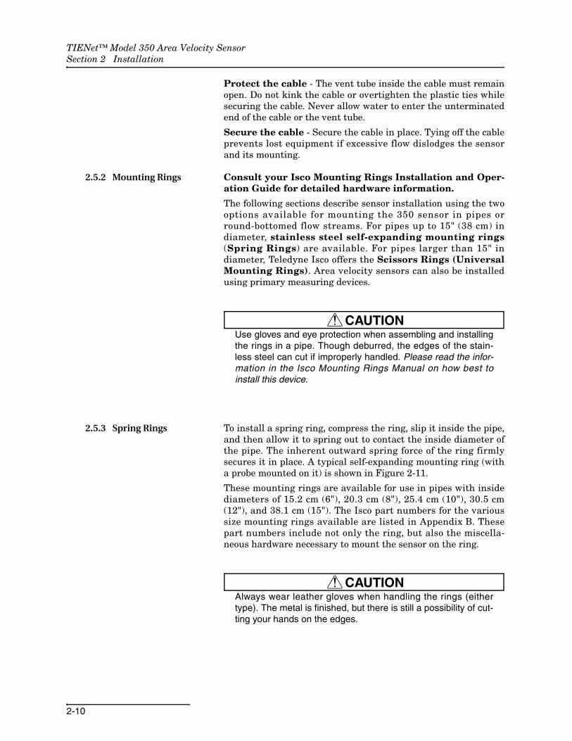
2.5.3 Spring Rings To install a spring ring, compress the ring, slip it inside the pipe,and then allow it to spring out to contact the inside diameter ofthe pipe. The inherent outward spring force of the ring firmlysecures it in place. A typical self-expanding mounting ring (witha probe mounted on it) is shown in Figure 2-11.
These mounting rings are available for use in pipes with insidediameters of 15.2 cm (6"), 20.3 cm (8"), 25.4 cm (10"), 30.5 cm(12"), and 38.1 cm (15"). The Isco part numbers for the varioussize mounting rings available are listed in Appendix B. Thesepart numbers include not only the ring, but also the miscella-neous hardware necessary to mount the sensor on the ring.
CAUTIONAlways wear leather gloves when handling the rings (eithertype). The metal is finished, but there is still a possibility of cut-ting your hands on the edges.
TIENet™ Model 350 Area Velocity SensorSection 2 Installation
2-11
Figure 2-11 Sensor Installed on a Spring Ring
Attaching the Sensor to the Ring
Attach the 350 sensor to the ring either by using two 4-40x3/8countersink screws or by snapping the optional probe carrier tothe ring. This second method of attaching the sensor allows foreasy removal in case service is needed later.
CAUTIONMake sure the slots on the sensor carrier are completelypressed into the tabs on the ring. This is particularly importantwhere there is any possibility of reverse flows, or where flowsare of high velocity. If the AV sensor is not fully pressed into themounting ring tabs, it might come loose in the stream, andcould possibly be damaged or lost.Make sure the sensor cable is securely fastened along theback (downstream) edge of the ring. Otherwise, the sensormay provide inaccurate level readings under conditions ofhigh velocity.
To complete the sensor-spring ring assembly procedure, attachthe sensor cable to the downstream edge of the ring. Follow thecable routing shown in Figure 2-11. Other routing may affectmeasurement accuracy. The cable can create a stilling well down-stream from the sensor, causing the level to read low. Use theself-locking plastic ties supplied with the ring. Install the ring inthe pipe by compressing it. Press inward on both sides and slidethe ring into the pipe.
Route the sensor cable out of the stream and secure it in positionby placing the ties through the holes in the mounting ring andthen locking them around the cable, as shown in Figure 2-11.
...outward force of ring against pipe wall holdsring in place inside pipe.
Compress ring into gap to install in pipe, then...
TIENet™ Model 350 Area Velocity SensorSection 2 Installation
2-12
CAUTIONDo not overtighten the plastic cable ties; they should be tight-ened just enough to secure the cable in place, without greatlyindenting the cable. Overtightening the plastic ties may col-lapse the reference tube in the cable, blocking it.
The spring ring may need anchoring. Under conditions of highvelocity (greater than 1.5 meters per second or 5 feet per second),the ring may not have sufficient outward spring force tomaintain a tight fit inside the pipe. The ring may start to lift offthe bottom of the pipe, or may even be carried downstream.
This problem is more prevalent in the larger diameter pipes andin pipes with smooth inside surfaces, such as plastic pipes. If anyof these conditions are present, or if movement of the mountingring is detected or suspected, you must anchor the ring in place.You can do this by setting screws through the ring into the pipe,or by other appropriate means. If there is a problem with thesmaller diameter rings, it may be sufficient to simply increasethe outward spring force of the ring by bending it into a lessround configuration.
2.5.4 Scissors Mounting Ring
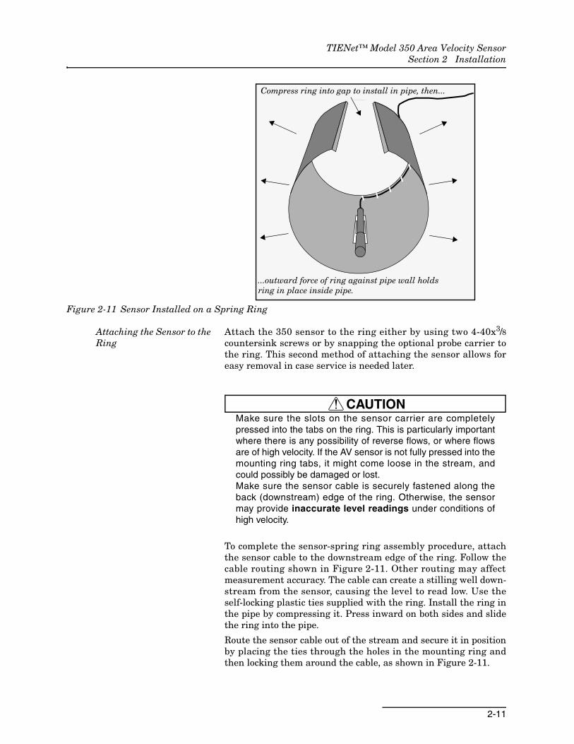
For pipes larger than 15" in diameter, Teledyne Isco offers theadjustable Scissors Ring (also known as the Universal MountingRing). This device consists of two or more metal strips that locktogether with tabs to form a single assembly. There is a basesection where the sensors are mounted, two or more extensionsections (usually), and a scissors section at the top that expandsthe entire assembly and tightens it inside the pipe. The scissorssection contains a long bolt that increases the length of thesection as it is tightened.
The assembled scissors rings fit pipe diameters from 16" to 80".Secure the unit in place by tightening the scissors mechanismwith a 5/8" socket wrench or other suitable tool. Ring sections are.040" thick half-hard 301 stainless steel sheet. All other parts arealso stainless steel, except for the plastic cable ties in thehardware kit.
Each extension, 1, 2, 3, and 4, adds 9.0", 21.5", 31.5", or 41.5",respectively, to the circumference of the ring. Used alone, thebase section fits a pipe that is approximately 16" to 19" indiameter. The 9.0" (smallest) extensions can be used to take up orremove slack, to bring the scissors mechanism into a positionwhere it can be effectively tightened.
TIENet™ Model 350 Area Velocity SensorSection 2 Installation
2-13
Figure 2-12 Scissors Ring adjustment
NoteThe hardware kit includes flat head bolts and nuts.TeledyneIsco strongly recommends bolting the assembled sectionstogether before installation, using the holes provided for thatpurpose. This can greatly increase safety and prevent theassembly from being torn apart.
Do not overtighten the mechanism. It is designed to flexsomewhat to provide a positive lock, once moderately tightened.
For installations in larger channels and/or high flow, extensions2, 3, and 4 have slots for attaching the ring to the channel wallusing appropriate anchoring hardware.
To prevent debris from catching on the probe cable, it isimportant to attach the cable to the mounting ring so it offers aslittle resistance to the flow as possible. Attach the sensor cable tothe downstream edge of the ring, using the self-locking plasticties supplied with the ring. Place the ties through the holes in themounting ring and then lock them around the cable.
CAUTIONDo not overtighten the plastic cable ties; they should be tight-ened just enough to secure the cable in place, without greatlyindenting the cable. Overtightening the plastic ties may col-lapse the reference tube in the cable, blocking it.
Scissors Assembly
Extensions
Base Section
Tighten the scissors assembly to expand the ring to press firmly against the inner pipe wall, securing the ring.
5/8" socketwrench
TIENet™ Model 350 Area Velocity SensorSection 2 Installation
2-14
2.5.5 Completing the Sensor Installation
The 350 sensor installation is finished by securing any excesssensor cable using cable clamps or other means.
The reference tube inside the cable can be restricted or blocked ifthe cable is kinked, sharply bent, coiled, or otherwise pinched.The sensor cable should be handled and mounted with care.
A damaged cable can affect the operation of the sensor, particu-larly if the reference air tube inside the cable is collapsed orblocked.
CAUTIONIf there is any distance between the point where the sensorcable leaves the mounting apparatus and the location of theflow meter, be sure to attach the cable to the flow stream wallto prevent it from moving, tangling, and trapping debris. Installthe cable so that it is not at risk of damage resulting from otheractivity taking place in the area.
2.6 Street Level Installation System
The Street Level Installation System provides a way to installIsco sensors in round pipe sewers without having to enter themanhole. The system includes an insertion tool with amulti-section pole and five differently-sized expansion rings (6",8", 10", 12", and 15") with an adjustable strap for each ring. Thesix pole extensions and the adjustable strap allow installation ofthe expansion rings in manholes as deep as 15 feet.
For more information about the Street Level Installation System,contact your Teledyne Isco representative.
2.7 Grounding Kit for Surge Protection
Added protection from lightning damage is available with thegrounding lug kit. This kit consists of a stainless steel terminalfor connecting a grounding conductor, and hardware to fasten itto a sensor mounting ring.
3-1
TIENet™ Model 350 Area Velocity Sensor
Section 3 Setup and Programming
3.1 Configuring the System
To configure the Signature flow meter for operation with the
TIENet 350 sensor, press MENU ( ) to access the top menu,and select Hardware Setup. For all TIENet devices including the350, select Smart Sensor Setup (TIENet).
3.1.1 Updating the Device List
When the 350 is physically added to the system, select PerformScan so that the flow meter detects it. When the scan is complete,the 350 appears in the list of connected devices, ready to be con-figured with the steps shown in Figure 3-2 on the following page.
NoteFrom the Hardware Setup menu, “Configure” refers to definingand selecting the parameters for each connected device.
The parameters that will appear for the 350 sensor are:
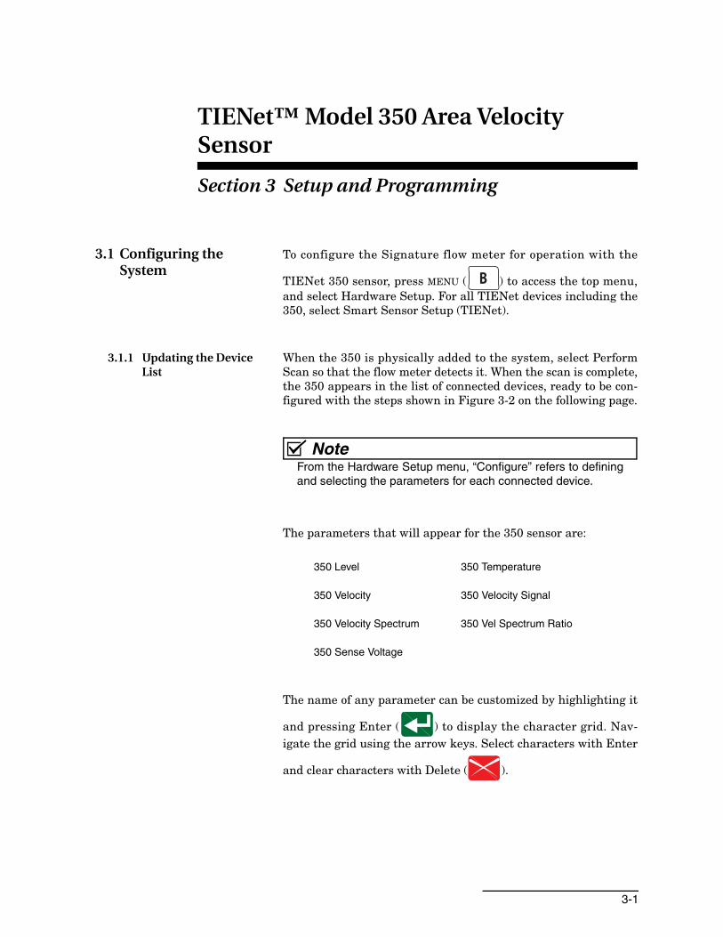
The name of any parameter can be customized by highlighting it
and pressing Enter ( ) to display the character grid. Nav-igate the grid using the arrow keys. Select characters with Enter
and clear characters with Delete ( ).
350 Level 350 Temperature
350 Velocity 350 Velocity Signal
350 Velocity Spectrum 350 Vel Spectrum Ratio
350 Sense Voltage

TIENet™ Model 350 Area Velocity SensorSection 3 Setup and Programming
3-2
Figure 3-1 Character grid
Done Cancel350 Velocity
A B C D E F G H I J K L M NbaZYXWVUTSRQPO
c d e f g h i j k l m n o p!:/zyxwvutsrq
@ # $ % ^ & * ( ) - _ + = <> ? , .

TIENet™ Model 350 Area Velocity SensorSection 3 Setup and Programming
3-3
Figure 3-2 Menu Tree: 350 Configuration
Configure Measurements
Smart Sensor Setup (TIENet)
• Perform Scan • Configure Measurements
350 Level
350 Velocity
350 Temperature
Select Operation
1. Hardware Setup
2. Configure
3. Administration
4. Home
Area Velocity Sensor
350 Velocity Signal
350 Velocity Spectrum 350 Vel Spectrum Ratio
350 Sense Voltage
Configure Measurements
Smart Sensor Configuration
The sensors are being
configured. Please wait...
Smart Sensor Setup (TIENet)
The sensors have been configured.
XXX Parameter
XXX Parameter
XXX Parameter
1 - XXX
Hardware Setup
1. Smart Sensor Setup (TIENet)
2. SDI-12 Setup
3. MODBUS Input Setup
4. MODBUS Output Setup
5. Modem Setup
Press Enter for a list ofsensors. Scroll to the 350and press Enter to select
Scroll with arrow keys tohighlight / select / deselectany displayed parameteror edit its name.
Press NEXT to confirmconfiguration. There maybe a slight delay.
With initial connection, beginby performing a hardwarescan to add the 350.
TIENet™ Model 350 Area Velocity SensorSection 3 Setup and Programming
3-4
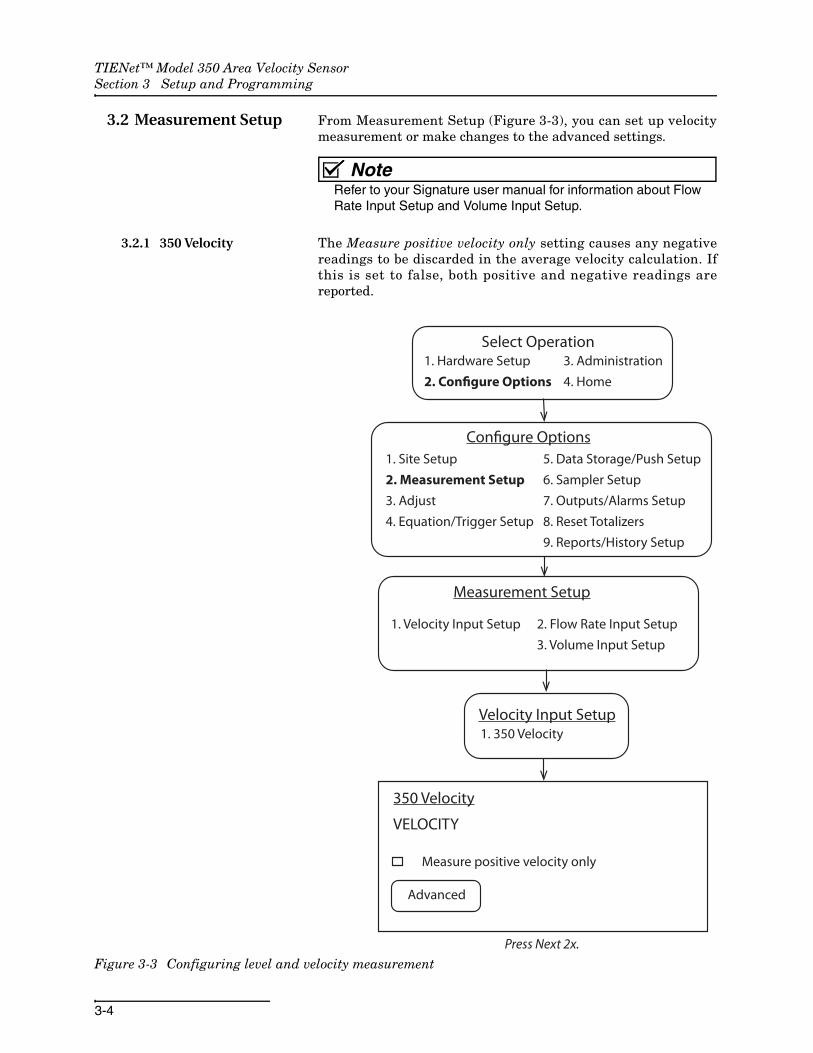
3.2 Measurement Setup From Measurement Setup (Figure 3-3), you can set up velocitymeasurement or make changes to the advanced settings.
NoteRefer to your Signature user manual for information about FlowRate Input Setup and Volume Input Setup.
3.2.1 350 Velocity The Measure positive velocity only setting causes any negativereadings to be discarded in the average velocity calculation. Ifthis is set to false, both positive and negative readings arereported.
Figure 3-3 Configuring level and velocity measurement
Configure Options
1. Velocity Input Setup 2. Flow Rate Input Setup
3. Volume Input Setup
Measurement Setup
Velocity Input Setup1. 350 Velocity
1. Site Setup
2. Measurement Setup
3. Adjust
4. Equation/Trigger Setup
5. Data Storage/Push Setup
6. Sampler Setup
7. Outputs/Alarms Setup
8. Reset Totalizers
9. Reports/History Setup
Press Next 2x.
350 Velocity
VELOCITY
Measure positive velocity only
Advanced
1. Hardware Setup
2. Configure Options
Select Operation3. Administration
4. Home

TIENet™ Model 350 Area Velocity SensorSection 3 Setup and Programming
3-5
3.2.2 Advanced Settings The sensor is pre-programmed at the factory with the AdvancedSettings for your application. Should your application requirethe addition of any correction factors, the Advanced button opensthe Advanced settings window (Figure 3-4).
Prior to making any changes to the Advanced settings, record thefactory settings in case you need to restore them later.
Input velocity coefficients can be adjusted for A, B, and C, where:
V = A (offset) + BV (slope) + CV2 (second-order parameter).
Figure 3-4 Measurement setup: Advanced settings for 350 AV sensor
Advanced
Input Velocity Coefficients
A:
B:
C:
Warning: Any changes to the
following data can adversely
affect the performance of this
Instrument!
Select BACK to cancel or NEXT to
continue.
A + (B * v) + (C * v2)
1
0
0

TIENet™ Model 350 Area Velocity SensorSection 3 Setup and Programming
3-6
3.2.3 Setting the 350 Level The Level Adjustment screen is accessed via the Shortcuts menuon the Signature. From this screen, you can also update thedisplay to show the current level of the stream.
Press SHORTCUTS ( ) and select Adjust Level.
Figure 3-5 350 Level adjustment screen
To set an initial or new level, enter the value in the field next toLevel, and select Adjust. To update the current reading, selectUpdate.
Prior to mounting the sensor in the flow stream, check the dis-played level reading. In open air, the reading should be zero. Ifnot, adjust the level to zero.
NoteIf the 350 sensor is part of the optional submerged functionalityfor a LaserFlow system, the initial level setting is the measureddistance from the bottom of the channel to the bottom of theLaserFlow sensor.
Following the 350 sensor installation in the flow stream, anothermeasurement device can be used to verify the 350 level reading.Allow the sensor to operate in the stream for approximately 30minutes prior to verifying the level.
350 Level
LEVEL ADJUSTMENT
Last reading: X.XXX ft
Time of last
adjustment: MM/DD/YYYY TT:TT:TT
Level:
Update
Adjustft
4-1
TIENet™ Model 350 Area Velocity Sensor
Section 4 Maintenance
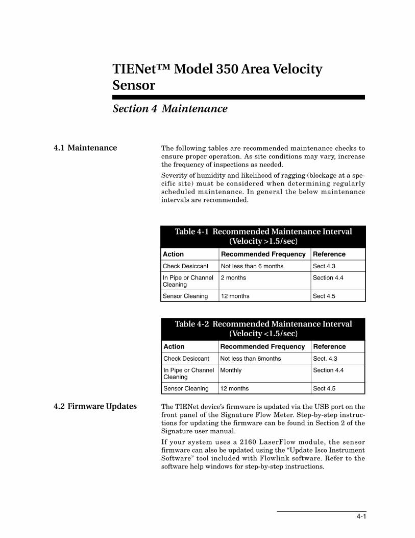
4.1 Maintenance The following tables are recommended maintenance checks toensure proper operation. As site conditions may vary, increasethe frequency of inspections as needed.
Severity of humidity and likelihood of ragging (blockage at a spe-cific site) must be considered when determining regularlyscheduled maintenance. In general the below maintenanceintervals are recommended.
4.2 Firmware Updates The TIENet device’s firmware is updated via the USB port on thefront panel of the Signature Flow Meter. Step-by-step instruc-tions for updating the firmware can be found in Section 2 of theSignature user manual.
If your system uses a 2160 LaserFlow module, the sensorfirmware can also be updated using the “Update Isco InstrumentSoftware” tool included with Flowlink software. Refer to thesoftware help windows for step-by-step instructions.
Table 4-1 Recommended Maintenance Interval (Velocity >1.5/sec)
Action Recommended Frequency Reference
Check Desiccant Not less than 6 months Sect.4.3
In Pipe or Channel Cleaning
2 months Section 4.4
Sensor Cleaning 12 months Sect 4.5
Table 4-2 Recommended Maintenance Interval (Velocity <1.5/sec)
Action Recommended Frequency Reference
Check Desiccant Not less than 6months Sect. 4.3
In Pipe or Channel Cleaning
Monthly Section 4.4
Sensor Cleaning 12 months Sect 4.5
TIENet™ Model 350 Area Velocity SensorSection 4 Maintenance
4-2
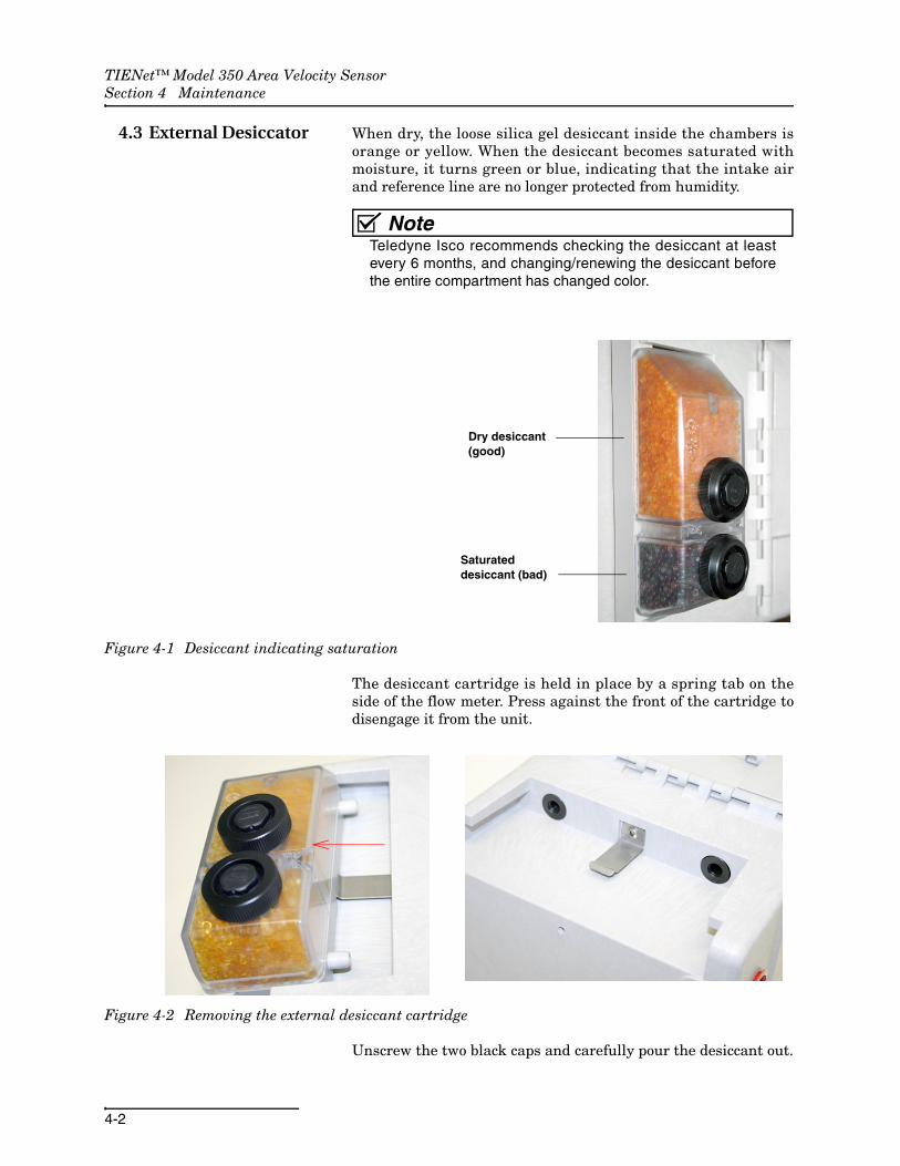
4.3 External Desiccator When dry, the loose silica gel desiccant inside the chambers isorange or yellow. When the desiccant becomes saturated withmoisture, it turns green or blue, indicating that the intake airand reference line are no longer protected from humidity.
NoteTeledyne Isco recommends checking the desiccant at leastevery 6 months, and changing/renewing the desiccant beforethe entire compartment has changed color.
Figure 4-1 Desiccant indicating saturation
The desiccant cartridge is held in place by a spring tab on theside of the flow meter. Press against the front of the cartridge todisengage it from the unit.
Figure 4-2 Removing the external desiccant cartridge
Unscrew the two black caps and carefully pour the desiccant out.
Dry desiccant(good)
Saturateddesiccant (bad)

TIENet™ Model 350 Area Velocity SensorSection 4 Maintenance
4-3
If removal is difficult, screw the caps back in and unscrew again.
Gently knock the caps and the cartridge against a hard surface tofree any small particles in the threads, as these can hinderproper sealing and cause wear.
Using a funnel, fill both chambers with dry desiccant, replace thecaps, ensuring that they are fully engaged. Press the cartridgeback into place on the side of the flow meter.
NoteIf this is a new desiccant cartridge, remove the two red protec-tive end caps from the ports before installing a new cartridge.
Figure 4-3 Opening the desiccant cartridge chambers
Renewing loose desiccant To renew the desiccant, spread it in a single layer on a flat metaltray. Place in a vented, circulating forced air, conventional ovenin a well ventilated room, and heat at 100 - 175°C (212 - 350°F)for about three hours, or until the color has returned to orange oryellow.
4.4 In Pipe or Channel Sensor Cleaning
Without removing the sensor from the flow stream, removedebris that may have collected in front of and around the sensoror has attached to the sensor. Use a stiff soft bristle brush suchas a broom or toilet bowl brush (do not use a steel brush). Attaching a stick to the brush, extending the handle, allowsaccess to hard to reach locations when cleaning the sensor. Usingthe brush, scrub in front of and around the sensor.
4.5 Cleaning The cable and outer surfaces of the 350 sensor can be cleanedwith mild detergent and warm water.
CAUTIONNever allow water to enter the unterminated end of the sensorcable or reference tube.
Use a funnel to refill the desiccator.
Remove red capsbefore installing cartridge.
TIENet™ Model 350 Area Velocity SensorSection 4 Maintenance
4-4
If the flow stream carries a great deal of debris, beware of organicmaterials that may collect beneath the 350 sensor. This materialswells as it becomes saturated with water and may exertpressure on the outer diaphragm. This can damage the trans-ducer and permanently disable the 350 sensor. Keeping the portsclean not only prevents damage, but ensures that the 350 sensorwill respond to the hydrostatic pressure above instead of thepressure created by swollen material.
If the ports become blocked:
1. Remove the sensor from its mounting ring, plate, or carrier.
2. Gently scrape any accumulated solids off the exterior of the sensor. Use a brush and flowing water.
3. Remove debris that has accumulated in the ports.
4. The outer diaphragm is behind the small metal cover on the bottom of the sensor. It should be visible through the two small openings at the center of the cover. Gently flush the cover and holes with water to remove debris.
CAUTIONNever remove the protective diaphragm cover. Avoid usingtools near the cover openings. Direct or indirect contact withthe outer diaphragm can permanently damage the 350 sensor.
4.6 Contact Teledyne Isco If you have further questions about the installation, operation,and maintenance of your TIENet device, please contact ourservice department at:
Teledyne Isco4700 Superior St.Lincoln, NE 68504
Phone: 866 298-6174 or 402 464-0231Fax: 402 465-3022E-mail: [email protected]

A-1
TIENet™ Model 350 Area Velocity Sensor
Appendix A Replacement Parts List
A.1 Replacement Parts Diagrams and Listings
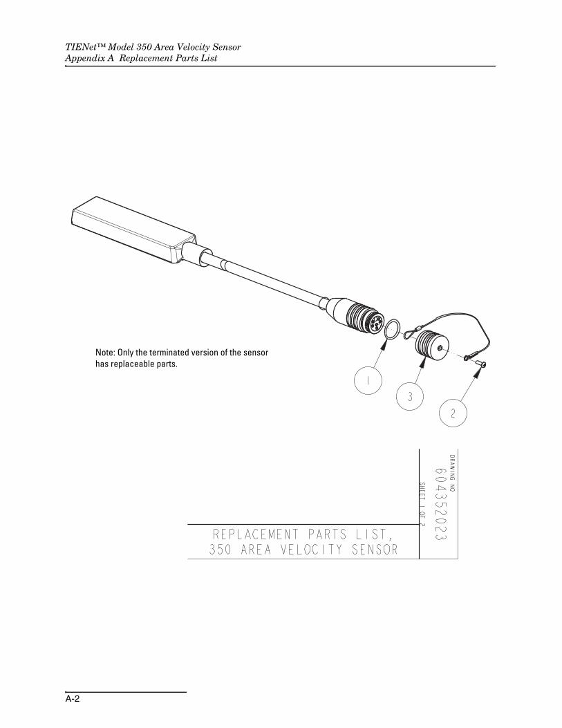
Replacement parts are called out in illustrations in this section.Reference the call-outs in the accompanying tables to determinethe part number for the item.
Replacement parts can be purchased by contacting TeledyneIsco’s Customer Service Department.
Teledyne IscoCustomer Service DepartmentP.O. Box 82531Lincoln, NE 68501 USA
Phone: (800) 228-4373(402) 464-0231FAX:(402) 465-3022
E-mail:[email protected]
TIENet™ Model 350 Area Velocity SensorAppendix A Replacement Parts List
A-2
Note: Only the terminated version of the sensorhas replaceable parts.

TIENet™ Model 350 Area Velocity SensorAppendix A Replacement Parts List
A-3

TIENet™ Model 350 Area Velocity SensorAppendix A Replacement Parts List
A-4
B-1
TIENet™ Model 350 Area Velocity Sensor
Appendix B Velocity Error Codes
B.1 Introduction Erroneous flow data can result from a number of factors. Thearea velocity system provides numbered error codes associatedwith the 350 Velocity data to assist in troubleshooting.
The error codes are viewable using Isco Flowlink® software. Def-initions of the error codes are provided in Table B-1. For furtherassistance, contact the factory.
B.2 Importing Data Dump (.ddp) Files
Flow data from the Signature Flow Meter can be downloadedonto a USB flash drive in the form of a .ddp (Data Dump) file.
To download the data:
1. Connect a flash drive to the USB port on the front panel of the Signature. From the USB Options menu, select Retrieve Data.
2. Select “All data,” or specify a start date or date range, and press NEXT. The data will be stored on the connected flash drive in a folder called “ISCO.”
3. Connect the flash drive to a computer running Flowlink.
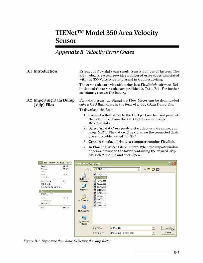
4. In Flowlink, select File > Import. When the import window appears, browse to the folder containing the desired .ddp file. Select the file and click Open.
Figure B-1 Signature flow data: Selecting the .ddp file(s)

TIENet™ Model 350 Area Velocity SensorAppendix B Velocity Error Codes
B-2
A progress window will appear, displaying the filename, sitename, device type, number of data types in the site file, andprogress of the download.
5. When the two progress bars have completed, click Done to close the window.
Figure B-2 Signature flow data: Importing the .ddp file
Upon completion, a new site file will appear in the Flowlinkworkspace.
TIENet™ Model 350 Area Velocity SensorAppendix B Velocity Error Codes
B-3
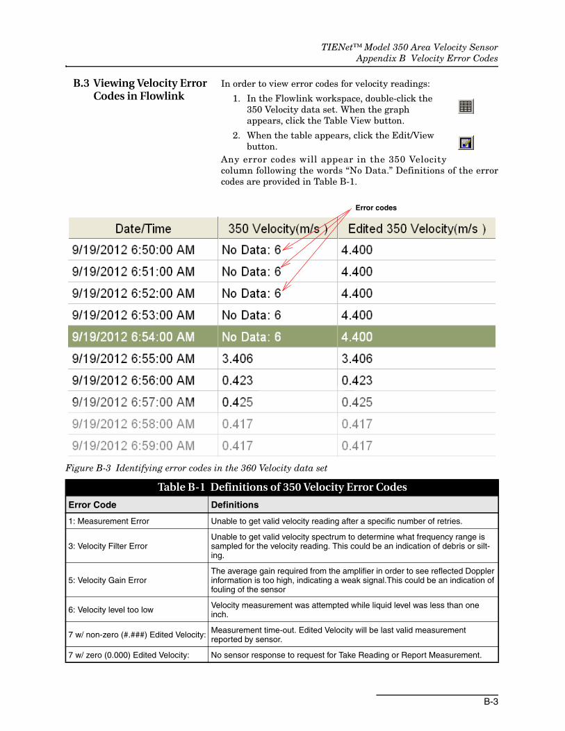
B.3 Viewing Velocity Error Codes in Flowlink
In order to view error codes for velocity readings:
1. In the Flowlink workspace, double-click the 350 Velocity data set. When the graph appears, click the Table View button.
2. When the table appears, click the Edit/View button.
Any error codes will appear in the 350 Velocitycolumn following the words “No Data.” Definitions of the errorcodes are provided in Table B-1.
Figure B-3 Identifying error codes in the 360 Velocity data set
Error codes
Table B-1 Definitions of 350 Velocity Error Codes
Error Code Definitions
1: Measurement Error Unable to get valid velocity reading after a specific number of retries.
3: Velocity Filter ErrorUnable to get valid velocity spectrum to determine what frequency range is sampled for the velocity reading. This could be an indication of debris or silt-ing.
5: Velocity Gain ErrorThe average gain required from the amplifier in order to see reflected Doppler information is too high, indicating a weak signal.This could be an indication of fouling of the sensor
6: Velocity level too low Velocity measurement was attempted while liquid level was less than one inch.
7 w/ non-zero (#.###) Edited Velocity: Measurement time-out. Edited Velocity will be last valid measurement reported by sensor.
7 w/ zero (0.000) Edited Velocity: No sensor response to request for Take Reading or Report Measurement.

TIENet™ Model 350 Area Velocity SensorAppendix B Velocity Error Codes
B-4

ROHS
Hazmat Table Signature Meter, Sensors and Accessories 60-4302-091 Rev.A
Name and amount of Hazardous Substances or Elements in the product
Component Name
Hazardous Substances or Elements
(Pb) (Hg) (Cd) (Cr(VI)) (PBB) (PBDE)
Circuit BoardsX O O O O O
DisplayX O O O O O
WiringO O O O O X
Internal CablesO O O O O X
DC MotorX O O O O X
ConnectorsO O X O O O
BatteryX X X O O O
Solenoid valveX O O O O X
Name and amount of Hazardous Substances or Elements in
the product
O: ST/
O: Represent the concentration of the hazardous substance in this component’s any homogeneous pieces is
lower than the ST/ standard limitation.
X ST/
( “X” )
X: Represent the concentration of the hazardous substance in this component’s at least one homogeneous
piece is higher than the ST/ standard limitation.
(Manufacturer may give technical reasons to the “X”marks)
The Environmentally Friendly Use Period (EFUP) was determined through experience.
(207 2007 )
A B
The date of Manufacture is in code within the serial number. The first three numbers are the year of
manufacture (207 is year 2007) followed by a letter for the month. "A" is January, "B" is February and so on.

Warranty
Teledyne Isco One Year Limited Factory Service Warranty* This warranty exclusively covers Teledyne Isco
instruments, providing a one-year limited warranty
covering parts and labor.
Any instrument that fails during the warranty period due to
faulty parts or workmanship will be repaired at the factory
at no charge to the customer. Teledyne Isco’s exclusive
liability is limited to repair or replacement of defective
instruments. Teledyne Isco is not liable for consequential
damages.
Teledyne Isco will pay surface transportation charges both
ways within the 48 contiguous United States if the
instrument proves to be defective within 30 days of
shipment. Throughout the remainder of the warranty period,
the customer will pay to return the instrument to Teledyne
Isco, and Teledyne Isco will pay surface transportation to
return the repaired instrument to the customer. Teledyne
Isco will not pay air freight or customer’s packing and
crating charges. This warranty does not cover loss, damage,
or defects resulting from transportation between the
customer’s facility and the repair facility.
The warranty for any instrument is the one in effect on date
of shipment. The warranty period begins on the shipping
date, unless Teledyne Isco agrees in writing to a different
date.
Excluded from this warranty are normal wear; expendable
items such as charts, ribbon, lamps, tubing, and glassware;
fittings and wetted parts of valves; and damage due to
corrosion, misuse, accident, or lack of proper maintenance.
This warranty does not cover products not sold under the
Teledyne Isco trademark or for which any other warranty is
specifically stated.
No item may be returned for warranty service without a
return authorization number issued by Teledyne Isco.
This warranty is expressly in lieu of all other warranties
and obligations and Teledyne Isco specifically disclaims
any warranty of merchantability or fitness for a
particular purpose.
The warrantor is Teledyne Isco, 4700 Superior, Lincoln, NE
68504, U.S.A.
* This warranty applies to the USA and countries where Teledyne Isco does not have an authorized dealer.
Customers in countries outside the USA, where Teledyne Isco has an authorized dealer, should contact their
Teledyne Isco dealer for warranty service.
Before returning any instrument for repair, please call, fax, or e-mail the Teledyne Isco Service Department for instructions. Many problems can often be diagnosed and corrected over the phone, or by e-mail, without returning the instrument to the factory. Instruments needing factory repair should be packed carefully, and shipped to the attention of the service department. Small, non-fragile items can be sent by insured parcel post. PLEASE BE SURE TO ENCLOSE A NOTE EXPLAINING THE PROBLEM.
Shipping Address: Teledyne Isco - Attention Repair Service 4700 Superior Street Lincoln, NE 68504 USA
Mailing Address: Teledyne Isco PO Box 82531 Lincoln, NE 68501 USA
Phone: Repair service: (800) 775-2965 (lab instruments) (866) 298-6174 (samplers & flow meters)
Sales & General Information: (800) 228-4373 (USA & Canada) Fax: (402) 465-3001 Email: [email protected]
February 28, 2012 P/N 60-1002-040 Rev G