TIENet 310 Ultrasonic Level Sensor - teledyneisco.com Meter... · TIENet™ 310 Ultrasonic Level...
42
TIENet® 310 Ultrasonic Level Sensor Installation and Operation Guide Ultrasonic Level Sensor Manual Body #69-4313-010 Copyright © 2012. All rights reserved, Teledyne Isco Revision C, May 2015
Transcript of TIENet 310 Ultrasonic Level Sensor - teledyneisco.com Meter... · TIENet™ 310 Ultrasonic Level...

TIENet® 310 UltrasonicLevel Sensor
Installation and Operation Guide
Ultrasonic Level Sensor
Manual Body #69-4313-010Copyright © 2012. All rights reserved, Teledyne IscoRevision C, May 2015


Foreword
This instruction manual is designed to help you gain a thorough understanding of the operation ofthe equipment. Teledyne Isco recommends that you read this manual completely before placing theequipment in service.
Although Teledyne Isco designs reliability into all equipment, there is always the possibility of amalfunction. This manual may help in diagnosing and repairing the malfunction.
If a problem persists, call or e-mail Teledyne Isco technical support for assistance. Simple difficul-ties can often be diagnosed over the phone. For faster service, please have your serial numberready.
If it is necessary to return the equipment to the factory for service, please follow the shippinginstructions provided by technical support, including the use of the Return Merchandise Authori-zation (RMA) specified. Be sure to include a note describing the malfunction. This will aid inthe prompt repair and return of the equipment.
Teledyne Isco welcomes suggestions that would improve the information presented in this manualor enhance the operation of the equipment itself.
Teledyne Isco is continually improving its products and reserves the right to change productspecifications, replacement parts, schematics, and instructions without notice.
Contact Information
Customer Service
Phone: (800) 228-4373 (USA, Canada, Mexico)
(402) 464-0231 (Outside North America)
Fax: (402) 465-3022
Email: [email protected]
Technical Support
Phone: Toll Free (866) 298-6174 (Samplers, Flow Meters and Multi-parameter Probes)
Toll Free (800) 775-2965 (Syringe Pumps and Liquid Chromatography)
Email: [email protected]
Return equipment to: 4700 Superior Street, Lincoln, NE 68504-1398
Other Correspondence
Mail to: P.O. Box 82531, Lincoln, NE 68501-2531
Email: [email protected]
Revised April 2014


TIENet™ 310 Ultrasonic Level SensorSafety
v
TIENet™ 310 Ultrasonic Level SensorSafety
General Warnings Before installing, operating, or maintaining this equipment, it isimperative that all hazards and preventive measures are fullyunderstood. While specific hazards may vary according tolocation and application, take heed of the following generalwarnings:
WARNINGAvoid hazardous practices! If you use this instrument in any way not specified in this manual, the protection provided by the instrument may be impaired.
AVERTISSEMENTÉviter les usages périlleux! Si vous utilisez cet instrument d’une manière autre que celles qui sont specifiées dans ce manuel, la protection fournie de l’instrument peut être affaiblie; cela augmentera votre risque de blessure.
Hazard Severity Levels This manual applies Hazard Severity Levels to the safety alerts,These three levels are described in the sample alerts below.
CAUTIONCautions identify a potential hazard, which if not avoided, mayresult in minor or moderate injury. This category can also warnyou of unsafe practices, or conditions that may cause propertydamage.
WARNINGWarnings identify a potentially hazardous condition, which if not avoided, could result in death or serious injury.
DANGERDANGER – limited to the most extreme situations to identify an imminent hazard, which if not avoided, will result in death or serious injury.

TIENet™ 310 Ultrasonic Level SensorSafety
vi
Hazard Symbols The equipment and this manual use symbols used to warn ofhazards. The symbols are explained below.
Hazard Symbols
Warnings and Cautions
The exclamation point within the triangle is a warning sign alerting you of important instructions in the instrument’s technical reference manual.
The lightning flash and arrowhead within the triangle is a warning sign alert-ing you of “dangerous voltage” inside the product.
Symboles de sécurité
Ce symbole signale l’existence d’instructions importantes relatives au produit dans ce manuel.
Ce symbole signale la présence d’un danger d’électocution.
Warnungen und Vorsichtshinweise
Das Ausrufezeichen in Dreieck ist ein Warnzeichen, das Sie darauf aufmerksam macht, daß wichtige Anleitungen zu diesem Handbuch gehören.
Der gepfeilte Blitz im Dreieck ist ein Warnzeichen, das Sei vor “gefährlichen Spannungen” im Inneren des Produkts warnt.
Advertencias y Precauciones
Esta señal le advierte sobre la importancia de las instrucciones del manual que acompañan a este producto.
Esta señal alerta sobre la presencia de alto voltaje en el interior del producto.

vii
TIENet™ Model 310 UltrasonicLevel Sensor
Table of Contents
Section 1 Introduction
1.1 Description. . . . . . . . . . . . . . . . . . . . . . . . . . . . . . . . . . . . . . . . . . . . . . . . . . . . . . . . . 1-11.2 310 Sensor Design . . . . . . . . . . . . . . . . . . . . . . . . . . . . . . . . . . . . . . . . . . . . . . . . . . . 1-21.3 Operation . . . . . . . . . . . . . . . . . . . . . . . . . . . . . . . . . . . . . . . . . . . . . . . . . . . . . . . . . . 1-21.4 Technical Specifications . . . . . . . . . . . . . . . . . . . . . . . . . . . . . . . . . . . . . . . . . . . . . . 1-31.5 Accessories . . . . . . . . . . . . . . . . . . . . . . . . . . . . . . . . . . . . . . . . . . . . . . . . . . . . . . . . . 1-4
1.5.1 Ordering Information . . . . . . . . . . . . . . . . . . . . . . . . . . . . . . . . . . . . . . . . . . 1-41.5.2 TIENet 310 Ultrasonic Level Sensor . . . . . . . . . . . . . . . . . . . . . . . . . . . . . . 1-5
Section 2 Installation and Setup for Signature
2.1 Sensor Installation Considerations . . . . . . . . . . . . . . . . . . . . . . . . . . . . . . . . . . . . . 2-12.1.1 Beam Angle . . . . . . . . . . . . . . . . . . . . . . . . . . . . . . . . . . . . . . . . . . . . . . . . . . 2-12.1.2 Humidity . . . . . . . . . . . . . . . . . . . . . . . . . . . . . . . . . . . . . . . . . . . . . . . . . . . . 2-12.1.3 Surface . . . . . . . . . . . . . . . . . . . . . . . . . . . . . . . . . . . . . . . . . . . . . . . . . . . . . . 2-12.1.4 Temperature . . . . . . . . . . . . . . . . . . . . . . . . . . . . . . . . . . . . . . . . . . . . . . . . . 2-12.1.5 Waves . . . . . . . . . . . . . . . . . . . . . . . . . . . . . . . . . . . . . . . . . . . . . . . . . . . . . . . 2-22.1.6 Wind . . . . . . . . . . . . . . . . . . . . . . . . . . . . . . . . . . . . . . . . . . . . . . . . . . . . . . . . 2-22.1.7 Hazardous Locations . . . . . . . . . . . . . . . . . . . . . . . . . . . . . . . . . . . . . . . . . . . 2-2
2.2 Connecting the Cable . . . . . . . . . . . . . . . . . . . . . . . . . . . . . . . . . . . . . . . . . . . . . . . . 2-22.2.1 Permanent Meters . . . . . . . . . . . . . . . . . . . . . . . . . . . . . . . . . . . . . . . . . . . . . 2-22.2.2 Connecting to Signature Portable via a TIENet Receptacle . . . . . . . . . . . . 2-5
2.3 Sensor Installation . . . . . . . . . . . . . . . . . . . . . . . . . . . . . . . . . . . . . . . . . . . . . . . . . . 2-62.3.1 Dead Band . . . . . . . . . . . . . . . . . . . . . . . . . . . . . . . . . . . . . . . . . . . . . . . . . . . 2-72.3.2 Submersion and Fouling . . . . . . . . . . . . . . . . . . . . . . . . . . . . . . . . . . . . . . . . 2-72.3.3 Mounting Options . . . . . . . . . . . . . . . . . . . . . . . . . . . . . . . . . . . . . . . . . . . . . 2-7
2.4 Installation in Hazardous Locations . . . . . . . . . . . . . . . . . . . . . . . . . . . . . . . . . . . . 2-82.4.1 Important Information Regarding “X” Marking . . . . . . . . . . . . . . . . . . . . . 2-92.4.2 Electrical Requirements . . . . . . . . . . . . . . . . . . . . . . . . . . . . . . . . . . . . . . . 2-102.4.3 Ambient Environment . . . . . . . . . . . . . . . . . . . . . . . . . . . . . . . . . . . . . . . . . 2-10
2.5 Configuring the System . . . . . . . . . . . . . . . . . . . . . . . . . . . . . . . . . . . . . . . . . . . . . 2-142.5.1 Updating the Device List . . . . . . . . . . . . . . . . . . . . . . . . . . . . . . . . . . . . . . . 2-142.5.2 Measurement Setup . . . . . . . . . . . . . . . . . . . . . . . . . . . . . . . . . . . . . . . . . . . 2-16
2.6 Level Calibration. . . . . . . . . . . . . . . . . . . . . . . . . . . . . . . . . . . . . . . . . . . . . . . . . . . 2-172.7 Firmware Updates . . . . . . . . . . . . . . . . . . . . . . . . . . . . . . . . . . . . . . . . . . . . . . . . . 2-182.8 Troubleshooting TIENet 310 USLS . . . . . . . . . . . . . . . . . . . . . . . . . . . . . . . . . . . . 2-182.9 Contact Teledyne Isco . . . . . . . . . . . . . . . . . . . . . . . . . . . . . . . . . . . . . . . . . . . . . . . 2-18A.1 Replacement Parts . . . . . . . . . . . . . . . . . . . . . . . . . . . . . . . . . . . . . . . . . . . . . . . . . . A-1
A.1.1 TIENet 310 Ultrasonic Level Sensor Replacement Parts . . . . . . . . . . . . . . A-2

TIENet™ Model 310 Ultrasonic Level SensorTable of Contents
viii
List of Figures1-1 Basic Signature monitoring system with 310
(mounting hardware not shown) . . . . . . . . . . . . . . . . . . . . . . . . . . . . . . . . . . . . . . . 1-11-2 310 Ultrasonic TIENet Sensor with unterminated leads (l) or TIENet plug (r) . 1-22-1 TIENet Device terminal strips . . . . . . . . . . . . . . . . . . . . . . . . . . . . . . . . . . . . . . . . 2-32-2 Installing cable with a cord-grip fitting . . . . . . . . . . . . . . . . . . . . . . . . . . . . . . . . . 2-32-3 TIENet Device terminal connections . . . . . . . . . . . . . . . . . . . . . . . . . . . . . . . . . . . 2-42-4 Attach wired terminal strip to case board socket . . . . . . . . . . . . . . . . . . . . . . . . . . 2-42-5 Position and secure the cable . . . . . . . . . . . . . . . . . . . . . . . . . . . . . . . . . . . . . . . . . . 2-52-6 How to connect a TIENet plug to the Signature Portable . . . . . . . . . . . . . . . . . . . 2-62-7 Sensor mounting options . . . . . . . . . . . . . . . . . . . . . . . . . . . . . . . . . . . . . . . . . . . . . 2-82-8 Sensor labeling regarding hazloc installations . . . . . . . . . . . . . . . . . . . . . . . . . . . 2-112-9 Hazardous Location Installation Control Drawing-Atex . . . . . . . . . . . . . . . . . . . 2-122-10 Hazardous Location Installation Control Drawing-CSA . . . . . . . . . . . . . . . . . . 2-132-11 Character grid . . . . . . . . . . . . . . . . . . . . . . . . . . . . . . . . . . . . . . . . . . . . . . . . . . . 2-142-12 Menu Tree: 310 Configuration . . . . . . . . . . . . . . . . . . . . . . . . . . . . . . . . . . . . . . . 2-152-13 Configuring ultrasonic level measurement . . . . . . . . . . . . . . . . . . . . . . . . . . . . . 2-162-14 Ultrasonic level adjustment and calibration . . . . . . . . . . . . . . . . . . . . . . . . . . . 2-17

1-1
TIENet® Model 310 UltrasonicLevel Sensor
Section 1 Introduction
The Signature® Flow Meter uses the TIENet 310 Device toprovide non-contact liquid level measurement. The flow meterhas built-in level-to-flow conversions that cover the majority ofopen channel flow measurement situations.
1.1 Description The ultrasonic sensor is mounted over the flow stream. The flowmeter measures the time interval between transmission of asound pulse from the sensor, and receiving its echo off the surfaceof the liquid, to determine the level of the stream.
Figure 1-1 Basic Signature monitoring system with 310(mounting hardware not shown)
Signature Flow Meter
310 TIENet Sensor

TIENet® Model 310 Ultrasonic Level SensorSection 1 Introduction
1-2
This non-contact measurement method reduces the frequency ofmaintenance, and is ideal for applications where the flow maycontain chemicals, grease, silt, or suspended solids.
1.2 310 Sensor Design The ultrasonic level sensor consists of a housing with a singletransducer that is both pulse transmitter and echo receiver. Atemperature sensor within the housing measures the ambienttemperature, and a microprocessor automatically compensatesfor speed-of-sound changes due to any changes in air temper-ature.
The 310 is available with a 10m, 23m, and special order to 150mor less cable lengths with or without connectors. For greater dis-tances, external connection via conduit, and connection of addi-tional TIENet devices, the TIENet Expansion Box is available.Bulk TIENet cable may also be used for greater distances.
Figure 1-2 310 Ultrasonic TIENet Sensor with unterminated leads (l) or TIENet plug (r)
1.3 Operation The sensor emits multiple ultrasonic pulses per second. Betweenpulses, the transducer switches from transmitter to receiver.When the transducer receives the echo from the water’s surface,the sound energy is converted into an electrical signal. Thesignal is then amplified and processed by the Signature flowmeter into an “echo-received” signal. The time between the trans-mitted pulse and the echo-received signal is proportional to thedistance between the transducer and the liquid surface. This dis-tance in turn determines the liquid level used to calculate flow.

TIENet® Model 310 Ultrasonic Level SensorSection 1 Introduction
1-3
1.4 Technical Specifications
Table 1-1 310 TIENet Device Specificationsa
Sensor Dimensions 3.63" x 4" tall (9.1cm x 10.2cm tall)
Cable Length 10 or 23 meters standard (32.8 or 75.5ft) standard
Mounting Attachment 3/4" NPT Pipe thread nipple w/ Conduit lock nut
Weight 4 lbs (1.8 kg)
Body Material PVDF
Enclosure IP68 when connected and properly sealed with cord-grip fitting.
Temperature RangeOperating (compensated)StorageHazardous Locations
-22 to 140°F (-30 to 60°C)-40 to 158°F (-40 to 70°C)-40 to 140°F (-40 to 60°C)
Measurement Range Minimum: 1 ft (0.3m) from sensor to liquid surfaceMaximum: 11 ft (3.3m) from sensor to liquid at minimum level
Measurement Accuracyat 72 °F (22 °C)
±0.02ft (0.006m) at 1ft level change or less;±0.03ft (0.009m) at greater than 1ft level change
Temperature Coefficient within compensated range
± 0.0002 x D (m) per degree C± 0.00011 x D (ft) per degree F
(Where D is the distance from the transducer to the liquid surface)
Beam Angle 10° 5° From center line
Ultrasonic Signal 50KHz
Certifications Group II, Category 1G (zone 0), T4Class I, Division 1 (and Zone 0), T4
a. All specifications are subject to change without notice.

TIENet® Model 310 Ultrasonic Level SensorSection 1 Introduction
1-4
1.5 Accessories Accessories used in sensor installation are briefly describedbelow. Refer to the next section for ordering information.
NoteOnly the Wall Mount Bracket is approved for use in classifiedhazardous locations. Other accessories must undergo a haz-ardous location evaluation in order to fulfill safe installationrequirements.
Spreader Bar – The Spreader Bar is an expandable pipe forsuspending equipment inside a manhole. Outward springpressure secures it against the manhole walls, like a showercurtain rod. Depending on your application, you can thensuspend the 310 TIENet Device, or the Signature Flow Meteritself, from the bar.
Cable Straightener – The cable straightener is designed foruse in installations where the transducer is suspended by itscable only, such as from the Spreader Bar. The straightener helpshold the transducer vertically plumb, thereby stabilizingalignment.
Cable Clamp – The cable clamp is used with the Spreader Barto secure the mounting of the sensor.
Wall Mount Bracket – This device lets you install the ultra-sonic level sensor on a convenient nearby wall over a flowstream, such as the side of a bridge, or other structure.
Floor Mount – The Ultrasonic Floor Mount is a collapsiblemetal stand attached to the floor, for extending the sensor outover a flow stream.
Ultrasonic Calibration Target – This option is designed tomake calibration of the level sensor more accurate during theinstallation process by letting you calibrate the level sensor fromoutside the manhole.
Sunshade – The ultrasonic sunshade is a white plastic cap thatfits over the top of the ultrasonic transducer. Its purpose is tokeep sunlight from heating the body of the level transducer andintroducing temperature errors to the internal temperature com-pensation.
1.5.1 Ordering Information Options and accessories can be purchased by contacting TeledyneIsco’s Customer Service Department.
Teledyne IscoCustomer Service Dept.P.O. Box 82531Lincoln, NE 68501 USAPhone: 800 228-4373
402 464-0231FAX: 402 465-3022E-mail:[email protected]

TIENet® Model 310 Ultrasonic Level SensorSection 1 Introduction
1-5
1.5.2 TIENet 310 Ultrasonic Level Sensor
310 Ultrasonic Level Sensor with Signature connection ending in unterminated leads. For use with Signature 6 position plug-in (green) terminal strip.Includes cord grip and sensor with cable. (See cable lengths below). 310 Ultrasonic sensor w/ 10m cable ........................................................................................ 60-4314-005310 Ultrasonic sensor w/ 23m cable ........................................................................................ 60-4314-006310 Ultrasonic sensor Cut-to-length ....................................................................................... 60-4314-014Cut to length cable up to 999 ft* ............................................................................................. 60-4304-050*Cable lengths can go up to 150 m with an expansion box.
310 Ultrasonic Level Sensor with Signature connection ending in TIENet plug. For use with portable Signature TIENet receptacle.Includes cord grip and sensor with cable. (See cable lengths below). 310 Ultrasonic sensor w/ connector and 10m cable ................................................................ 60-4314-009310 Ultrasonic sensor w/ connector and 23m cable ................................................................ 60-4314-011310 Ultrasonic sensor w/ connector Cut-to-length*................................................................ 60-4314-013Cable Assembly with TIENet Y w/ connector ......................................................................... 60-4304-066*Cable lengths can go up to 150 m with an expansion box. Sunshade for ultrasonic sensor ............................................................................................... 60-3004-142Spreader bar for suspension of sensor or flow meter in manhole shaft ................................ 60-3004-110Cable clamp .............................................................................................................................. 60-3004-129Sensor Mounting Bracket U/S ................................................................................................. 60-2003-615Floor mount for horizontal surfaces ........................................................................................ 60-2004-611Cable straightener for suspension over stream...................................................................... 60-4313-009Ultrasonic calibration target ................................................................................................... 60-3004-143TIENet Expansion Box ............................................................................................................ 60-4307-023
Kit includes 10ft TIENet cable
Cord grip fitting, 3/4" NPT, for TIENet cable........................................................................... 209-0073-12Barrier for Signature (SPA 2060) ............................................................................................ 60-5324-060
NoteTeledyne Isco uses FreeRTOS version 5.4.2 in its TIENetdevices. In accordance with the FreeRTOS license, FreeRTOSsource code is available on request. For more information, visitwww.FreeRTOS.org.

TIENet® Model 310 Ultrasonic Level SensorSection 1 Introduction
1-6

2-1
TIENet® Model 310 UltrasonicLevel Sensor
Section 2 Installation and Setup for Signature
The Signature Flow Meter does not have to be mounted near theflow stream. You can install the flow meter itself at a convenient,protected location and route the sensor cable to the measurementpoint. Proper installation of the 310 sensor is critical for accuratemeasurement.
2.1 Sensor Installation Considerations
Measurement accuracy can be affected by a number of sitefactors that should be taken into consideration when selectingthe location for the sensor. If the sensor cannot obtain a validreading, an asterisk (*) will appear next to the displayed level,indicating there is an error.
2.1.1 Beam Angle The 310 sensor has a 10° beam angle, forming a cone whose apexis the ultrasonic transducer. The sensor can only detect surfaceswithin this cone. Narrow channels can result in false echoes andincorrect level readings off the walls and sides of the channel. Forpreventive measures, see Section 2.5.2 Measurement Setup, andthe programming steps in Figure 2-14.
The beam becomes narrower at shorter distances, which canincrease difficulty in detecting the return echo. If the beam is toowide, the sensor may pick up signals from unwanted surfaces,such as the walls of the channel.
Sensor elevation is highly specific to the particular site.
2.1.2 Humidity Conditions of extremely high or low humidity can cause detectionto occur either earlier or later than under normal conditions. Adrop in water level, normally compensated for by the sensor’sinterval-based amplifier, may produce errors in echo detection.
Additionally, water droplet condensation on the bottom surface ofthe sensor can cause measurement errors.
2.1.3 Surface Solids, foam, oil, and turbulence can all absorb or weaken theultrasonic pulses, causing errors in detection. Foam or oil on thesurface of the stream can produce false level readings.
2.1.4 Temperature Changes in ambient temperature significantly affect the velocityof sound. If ambient temperature changes rapidly, there may be adelay before the 310’s temperature sensor can activate temper-ature compensation.
If the sensor will be installed outdoors in direct sunlight, use asunshade to prevent heating of the sensor housing.
TIENet® Model 310 Ultrasonic Level SensorSection 2 Installation and Setup for Signature
2-2
2.1.5 Waves Waves on the surface of the flow stream can deflect the ultrasonicsignal, causing erroneous readings or total loss of signal. TheSignature Flow Meter software is able to reject occasionalreadings that deviate substantially from normal.
2.1.6 Wind Strong winds can significantly reduce the strength of the returnecho. Narrow beams can result in the sound being blown away;likewise, greater distances to the flow stream surface are moresubject to distortion in strong winds.
2.1.7 Hazardous Locations Installation in classified hazardous locations must meet specificconditions in order to fulfill safety requirements. Installationmust be performed only by trained, qualified personnel. Refer toSection 2.4 Installation in Hazardous Locations for completeinformation.
2.2 Connecting the Cable External TIENet devices such as the 310 are all connected to theSignature flow meter in the same manner. These connectionsusually use conduit or cord-grip cable fittings for permanentmounted meter or with TIENet receptacle for portable meters.Multiple external TIENet devices can be connected simultane-ously.
Refer to your Signature flow meter manual for instructions onaccessing the instrument’s interior components.
NoteThe steps that follow include instructions for installing cord-gripfittings. Some applications will require cables to be routedthrough user-supplied conduit. Conduit with a minimum 3/4" IDis suggested for unterminated sensor cables and conduit withminimum 1-1/2” ID is suggested for straight runs for sensorcables with connectors.
2.2.1 Permanent Meters
NoteBefore proceeding, ensure that the flow meter has been dis-connected from mains power.

TIENet® Model 310 Ultrasonic Level SensorSection 2 Installation and Setup for Signature
2-3
1. Remove one of the 6-position plug-in terminal strip connec-tors from the case board.
Figure 2-1 TIENet Device terminal strips
2. If using a cord-grip fitting, install the cable nut in the appropriate opening on the bottom of the Signature enclo-sure, securing it to the wall with the lock nut (concave side facing wall).
3. Feed the TIENet device cable end through the sealing nut and seal, and through the cable nut. Lightly tighten the sealing nut, just enough to hold the cable in place while installing the connector.
Figure 2-2 Installing cable with a cord-grip fitting
4. Attach the wire ends to the terminal strip as shown in Figure 2-3, then press the terminal strip back down into its socket on the case board, as shown in Figure 2-4, taking care not to strain any wire connections. Gently tug each wire when finished, to verify secure connection to the screw terminals.
Lock Nut(concave side facing wall)
Cable NutSeal
(color may vary)
Sealing Nut

TIENet® Model 310 Ultrasonic Level SensorSection 2 Installation and Setup for Signature
2-4
NoteThe SHIELD wire is the bare drain emerging from the foilshie ld around the YELLOW and BROWN wires. TheBRAID-DRAIN wire is the bare drain emerging from the sur-rounding braided shield inside the cable jacket. It is not neces-sary to prevent the two braids from coming into contact witheach other.The drain wires need to be kept very short.
Figure 2-3 TIENet Device terminal connections
5. Press the terminal strip back down into its socket on the case board, as shown in Figure 2-5, taking care not to strain any wire connections. The 310 sensor cable does not include a reference air connection (Figure 2-4).
Figure 2-4 Attach wired terminal strip to case board socket
Braid-Drain
Shield

TIENet® Model 310 Ultrasonic Level SensorSection 2 Installation and Setup for Signature
2-5
6. Gently tug the cable downward, to remove any slack within the enclosure, taking care not to put any stress on the con-nection.
7. Tighten the cord grip sealing nut.
CAUTIONIf you are using conduit instead of the cord-grip fitting, the con-duit must be sealed to prevent harmful gases and moisturefrom entering the Signature enclosure. Failure to seal conduitcould reduce equipment life.
8. Close the front panel and fasten it shut with the two Phil-lips screws.
Figure 2-5 Position and secure the cable
2.2.2 Connecting to Signature Portable via a TIENet Receptacle
The optional external TIENet devices compatible with the Sig-nature Portable (and Signature) all scan into the hardware in thesame manner. A scan is required anytime a new TIENet device isadded. Multiple TIENet devices can be connected simultaneously to thesame Signature Portable Flow Meter. The following TIENetdevices will attach to the TIENet receptacle:
• Ultrasonic Level Sensor

TIENet® Model 310 Ultrasonic Level SensorSection 2 Installation and Setup for Signature
2-6
• Area Velocity Sensor
• 301 pH Interface
• LaserFlow
• 306 Sampler InterfaceConnecting a TIENet plug to the Signature Portable
To connect the TIENet plug from the sensor to the TIENet Recep-tacle:
1. Align the connectors and push together (Figure 2-6).
2. After the physical connection is made, a scan must be per-formed for the device to be recognized.
For additional TIENet connections, use the TIENet Y-cable oralternately an Expansion Box.
O-Ring and Lubrication for the TIENet receptacle
1. Coat the O-ring’s sealing surface with a silicone lubricant.
CAUTIONDo not use petroleum-based lubricants. Petroleum-basedlubricants will cause the O-ring to swell and eventually deterio-rate. Aerosol silicone lubricant sprays often use petro-leum-based propellents. If you are using an aerosol spray,allow a few minutes for the propellent to evaporate before pro-ceeding.
2. Align and insert the connector. The sensor release will “click” when the sensor connector is fully seated.
3. Connect the two caps together.
Figure 2-6 How to connect a TIENet plug to the Signature Portable
2.3 Sensor Installation The mounting location of the ultrasonic level sensor depends onthe type of primary measuring device (such as a weir or flume),and on the method of level-to-flow conversion used. Refer to theIsco Open Channel Flow Measurement Handbook included withyour Signature flow meter, or to instructions provided by themanufacturer of the primary device, for detailed informationabout locating the measuring point.

TIENet® Model 310 Ultrasonic Level SensorSection 2 Installation and Setup for Signature
2-7
If you intend to measure flow by some other means, such as agravity flow equation (Manning) or by calibrating a section of theflow channel, you must locate the measuring point based on thehydraulic characteristics of the channel, as well as thelevel-to-flow conversion method.
In most open channel installations where the level may exceedone-half of full pipe, mount the sensor as near as possible to themidpoint between the entrance and exit to measure over theleast turbulent flow.
2.3.1 Dead Band Mount the sensor as close as possible to one foot (0.3 m) abovemaximum expected level. The sensor cannot measure within thefoot of space directly below it, called the dead band.
2.3.2 Submersion and Fouling
Fouling by grease or solids can cause the sensor to malfunction.The sensor is sealed, so unless it was exposed to corrosive sub-stances, temporary accidental submersion should not harm it.Upon retrieval, ensure that the sensor’s surface is clean. Cleanthe bottom surface very gently with running water and a softcloth.
2.3.3 Mounting Options The 310 sensor can be mounted over the flow stream in variousways, depending on which method best fits the application.
Optional equipment is available from Teledyne Isco for wall,floor, suspension, and horizontal mounting (see Section 1.5Accessories). The sensor has a 3/4" NPT male pipe thread with aconduit lock nut to connect it to a mounting bracket or cablestiffener. The sensor cable can be routed through user-providedconduit back to the Signature Flow Meter.
Regardless of the mounting method you select, always place thesensor over the center of the stream, and always use a circularbubble level for vertical alignment.

TIENet® Model 310 Ultrasonic Level SensorSection 2 Installation and Setup for Signature
2-8
Figure 2-7 Sensor mounting options
2.4 Installation in Hazardous Locations
Read all labels carefully before installing the equipment!
The TIENet Model 310 device is ATEX-approved for use in poten-tially explosive atmospheres when specific conditions are met, asdescribed in this section in reference to “X” Marking.
The 310 is Group II, Category 1G equipment for use in gashazard zones 0, 1, and 2 (European standards), or Class IDivision 1 (North American standards).
The braid-drain lead depicted in Figure 2-8 Sensor labelingregarding hazloc installations is normally bonded to earththrough the Signature connector case terminals or conduit; it isalso electrically connected to the anti-static conductive housingof the 310 sensor.
Installation must be performed only by trained, qualified per-sonnel.
Wall MountApproved for classified hazardous locations.
Floor StandNot approved for classified hazardous locations.
Suspension (cable straightener recommended)Not approved for classified hazardous locations.

TIENet® Model 310 Ultrasonic Level SensorSection 2 Installation and Setup for Signature
2-9
Barriers or isolators required for certifiable safe installation arethe responsibility of the user. Refer to the control drawings pro-vided in Figures 2-9 and 2-10.
NoteThere is TIENet barrier (a weatherproof box with terminals andpower supply) available for hazardous locations (PN# 60-5324-060). Contact Teledyne Isco's SPA departmentfor more details.
NoteOnly the Wall Mount Bracket is approved for use in classifiedhazardous locations. Non-Isco hardware must undergo a haz-ardous location evaluation in order to fulfill safe installationrequirements.
WARNINGThe mounting bracket is a potential isolated charge carrier. For classified hazardous locations, your installation MUST satisfy earthing requirements. Refer to IEC 60079-14 section 12.2.4 and IEC 60079-11.
Serpentine loopWARNING
Do not coil the sensor cable; this will form an inductor and create a hazard. The cable should be kept as short as is practical. If necessary, use a serpentine loop (see figure at left) instead.
2.4.1 Important Information Regarding “X” Marking
The ATEX labeling on the serial tag of the 310 device includes anumber ending in “X.” The X marking indicates that there arespecific conditions that must be met in order for the equipment tocomply with intrinsic safety requirements. Refer to Figure 2-8 onthe following page.
These specific conditions are as follows:
• The integral cable must be terminated in a manner suitable for the zone of installation.
• No additional cable must be added to the sensor during the installation and the sensor integral cable must be connected directly to the terminals of the associated apparatus.
• The Li and Ci of the associated apparatus must be negli-gible.
• The physical spacing between the exposed ends of each insulated wire lead, and earth ground and other IS

TIENet® Model 310 Ultrasonic Level SensorSection 2 Installation and Setup for Signature
2-10
circuits, must be such that the equipment is isolated up to 500V, and to 1500V for non-IS circuitry.
• The physical spacing between the end of the wire jacketing and the terminal to which a lead is connected must be such that solid foreign objects of 12.5mm and greater shall not be able to fully penetrate.
2.4.2 Electrical Requirements
Always refer to the electrical values listed at the bottom of the310 serial tag when connecting associated apparatus (i.e., powersupply, network interface, etc.).
This labeling indicates the maximum input voltage (Ui),maximum input current (Ii), and maximum power (Pi) that canbe present at the specified terminals without invalidatingintrinsic safety.
The power supply parameter allowances must exceed maximuminternal capacitance (Ci) and either the maximum internalinductance (Li), or the maximum internal inductance-to-resis-tance ratio (Li/Ri) of the 310 device and integral cable. Theseparameters are established on the third party certification reportand are available by contacting Teledyne Isco.
2.4.3 Ambient Environment Installation in designated hazardous areas must fall within thetemperature range of -40 to +60°C, as specified on the serial taglabeling.

TIENet® Model 310 Ultrasonic Level SensorSection 2 Installation and Setup for Signature
2-11
Figure 2-8 Sensor labeling regarding hazloc installations
Ui = Maximum input voltage
Ii = Maximum input current
Pi = Maximum power
No objects of 12.5mm or greater shall penetrate gap.
Spacing between bare wires and other wiring, circuitry, and earth ground, shall enable isolation to 500V.
Temperature range
Anti-StaticGrounding Protection
Refer to Section 2.4.1 for important information about ’X’ marking.

TIENet® Model 310 Ultrasonic Level SensorSection 2 Installation and Setup for Signature
2-12
Figure 2-9 Hazardous Location Installation Control Drawing-Atex

TIENet® Model 310 Ultrasonic Level SensorSection 2 Installation and Setup for Signature
2-13
Figure 2-10 Hazardous Location Installation Control Drawing-CSA

TIENet® Model 310 Ultrasonic Level SensorSection 2 Installation and Setup for Signature
2-14
2.5 Configuring the System
To configure the Signature flow meter for operation with the
TIENet 310 device, press MENU ( ) to access the top menu,and select Hardware Setup. For all TIENet devices including the310, select Smart Sensor Setup (TIENet).
2.5.1 Updating the Device List
When the 310 is physically added to the system, select PerformScan so that the flow meter detects it. When the scan is complete,the 310 appears in the list of connected devices, ready to be con-figured with the steps shown in Figure 2-12 on the followingpage.
NoteFrom the Hardware Setup menu, “Configure” refers to definingand selecting the parameters for each connected device.
The four parameters that will appear for the 310 device are:
310 Distance – Distance between the bottom of the sensor andthe surface of the flow stream.
310 Air Temperature – Temperature of surrounding (ambient)air
310 Level – Level of the flow stream surface
310 Signal – Strength of the return echo
The name of any parameter can be customized by highlighting it
and pressing Enter ( ) to display the character grid. Nav-igate the grid using the arrow keys. Select characters with Enter
and clear characters with Delete ( ).
Figure 2-11 Character grid
Done Cancel310 Distance
A B C D E F G H I J K L M NbaZYXWVUTSRQPO
c d e f g h i j k l m n o p!:/zyxwvutsrq
@ # $ % ^ & * ( ) - _ + = <> ? , .

TIENet® Model 310 Ultrasonic Level SensorSection 2 Installation and Setup for Signature
2-15
Figure 2-12 Menu Tree: 310 Configuration
Configure Measurements
Smart Sensor Setup (TIENet)• Perform Scan • Configure Measurements
310 Distance
310 Air Temperature
310 Level
Select Operation1. Hardware Setup2. Configure3. Administration4. Home
Ultrasonic Level Sensor
310 Signal
Configure Measurements
Smart Sensor ConfigurationThe sensors are beingconfigured. Please wait...
Smart Sensor Setup (TIENet)The sensors have been configured.
XXX Parameter
XXX Parameter
XXX Parameter
1 - XXX
Hardware Setup1. Smart Sensor Setup (TIENet)2. SDI-12 Setup3. MODBUS Input Setup4. MODBUS Output Setup5. Modem Setup
Press Enter for a list ofsensors. Scroll to the 310and press Enter to select
Scroll with arrow keys tohighlight / select / deselectany displayed parameteror edit its name.
Press NEXT to confirm configuration.There may be a slight delay.
With initial connection, beginby performing a hardwarescan to add the 310.

TIENet® Model 310 Ultrasonic Level SensorSection 2 Installation and Setup for Signature
2-16
2.5.2 Measurement Setup From Measurement Setup (Figure 2-13 below), select Level InputSetup to define the measurement range.
The Minimum Blanking Distance is the shortest distancefrom the sensor face (highest expected liquid level). Because ofthe dead band, this value can never be less than one foot.Depending on the elevation of your sensor, this value may beincreased to help ensure that echoes read by the flow meter comeonly from the surface of the flow stream, and not off the walls orsides of the channel.
The Maximum Blanking Distance is the distance between thesensor face and the bottom of the channel, or zero level. You canenter a slightly larger value than calculated, if you prefer.
Figure 2-13 Configuring ultrasonic level measurement
Configure Options
Level Input Setup
Measurement Setup1. Level Input Setup2. Flow Input Setup3. Volume Input Setup
1. 310 Level
310 Level
LEVEL
ft
ft
Blanking DistanceMinimum:Blanking DistanceMaximum:
0
3
1. Site Setup2. Measurement Setup3. Adjust4. Equation/Trigger Setup
5. Data Storage/Push Setup6. Sampler Setup7. Inputs/Outputs/Alarms Setup8. Reset Totalizers9. Reports/History Setup
1.
Press Next 2x.
Distance from sensor face tomaximum expected liquidlevel
Distance from sensor face tobottom of channel
Wall MountApproved for classified hazardous locations.

TIENet® Model 310 Ultrasonic Level SensorSection 2 Installation and Setup for Signature
2-17
2.6 Level Calibration Although all other programming steps can be performed off-site,level must be set at the measurement site following installation,at ambient temperature.
Once the sensor is installed over the flow stream, measure thepresent liquid level (see figure at left) and enter this value forLevel, under Adjust Options. Then highlight “Adjust” and pressEnter to confirm.
From this screen, you can also update the display to show thecurrent level of the stream.
Figure 2-14 Ultrasonic level adjustment and calibration
D
d
h
D – d = h (level)
Configure Options
Adjust1. Level
310 LevelLEVEL ADJUSTMENT
Adjust Level1. 310 Level
Last reading: X.XXX ft
Time of lastadjustment: MM/DD/YYYY TT:TT:TT
Update
AdjustftLevel:
1. Site Setup2. Measurement Setup3. Adjust4. Equation/Trigger Setup
5. Data Storage/Push Setup6. Sampler Setup7. Inputs/Outputs/Alarms Setup8. Reset Totalizers9. Reports/History Setup
Display currentreal-time level
Reset/calibratelevel

TIENet® Model 310 Ultrasonic Level SensorSection 2 Installation and Setup for Signature
2-18
2.7 Firmware Updates The TIENet device’s firmware is updated via the USB port on thefront panel of the Signature Flow Meter. Step-by-step instruc-tions for updating the firmware can be found in Section 2 of theSignature user manual.
2.8 Troubleshooting TIENet 310 USLS
2.9 Contact Teledyne Isco If you have further questions about the installation, operation,and maintenance of your TIENet device, please contact ourservice department at:
Teledyne Isco4700 Superior St.Lincoln, NE 68504
Phone: 866 298-6174 or 402 464-0231Fax: 402 465-3022E-mail: [email protected]
Table 2-1 Troubleshooting: TIENet 310 Ultrasonic Level Sensor
Symptom Cause Action
Invalid level, display has asterisk (*) by level reading
Not scanned Perform a smart sensor scan
Not able to achieve signal lock (misalignment, loose mounting, turbulence, foam, or debris in the water)
Adjust mounting or place over a solid surface.
Level outside of the Blanking distances Adjust min/max blanking distances
Not wired correctly Check/repair wiring
Open fuseReplace fuse FU-T 3.15A and rescan.Part #411-0212-70. Refer to Figure 3-2 Item K.
Failed sensor Replace with known good sensor
No level reading on the dis-play
Parameter not selected to be displayed on Home Display
Add the parameter to the Home Dis-play. Refer to Section 2.7.1 Site Setup.
Incorrect level reading
Level not adjusted properly Readjust level
Sensor misaligned Realign sensor
Objects in the path of the signal Adjust min/max blanking distances and/or reposition sensor.
Sensor exposed to direct sunlightInstall sunshade. Refer to Appendix Appendix B Options and Accessories.

A-1
TIENet® Model 310 UltrasonicLevel Sensor
Appendix A Replacement Parts
A.1 Replacement Parts Replacement parts are called out in the following illustrations.Refer to the call-out in the adjacent table to determine the partnumber for the item.
Replacement parts can be purchased by contacting TeledyneIsco’s Customer Service Department.
Teledyne IscoCustomer Service DepartmentP.O. Box 82531Lincoln, NE 68501 USA
Phone: (800) 228-4373(402) 464-0231FAX:(402) 465-3022
E-mail:[email protected]

TIENet® Model 310 Ultrasonic Level Sensor
A-2
A.1.1 TIENet 310 Ultrasonic Level Sensor Replacement Parts
Split mounting Nut .................................................................................................................. 60-4313-007Cap Sensor Connector .............................................................................................................. 60-4314-011310 Ultrasonic sensor Cut-to-length ....................................................................................... 60-4314-014O-Ring Sensor Connector ....................................................................................................... 20-2100-669Screw Connector Cap #4-40 X1/4 ............................................................................................ 23-1014-304

TIENet® Model 310 Ultrasonic Level Sensor
A-3

TIENet® Model 310 Ultrasonic Level Sensor
A-4

Compliance Statements
CE Dec
larat
ion o
f Con
form
ity
Hazmat Table Signature Meter, Sensors and Accessories 60-4302-091 Rev.A
Name and amount of Hazardous Substances or Elements in the product
Component Name
Hazardous Substances or Elements
(Pb) (Hg) (Cd) (Cr(VI)) (PBB) (PBDE)
Circuit BoardsX O O O O O
DisplayX O O O O O
WiringO O O O O X
Internal CablesO O O O O X
DC MotorX O O O O X
ConnectorsO O X O O O
BatteryX X X O O O
Solenoid valveX O O O O X
Name and amount of Hazardous Substances or Elements in
the product
O: ST/
O: Represent the concentration of the hazardous substance in this component’s any homogeneous pieces is
lower than the ST/ standard limitation.
X ST/
( “X” )
X: Represent the concentration of the hazardous substance in this component’s at least one homogeneous
piece is higher than the ST/ standard limitation.
(Manufacturer may give technical reasons to the “X”marks)
The Environmentally Friendly Use Period (EFUP) was determined through experience.
(207 2007 )
A B
The date of Manufacture is in code within the serial number. The first three numbers are the year of
manufacture (207 is year 2007) followed by a letter for the month. "A" is January, "B" is February and so on.

CE Dec
larat
ion o
f Con
form
ity
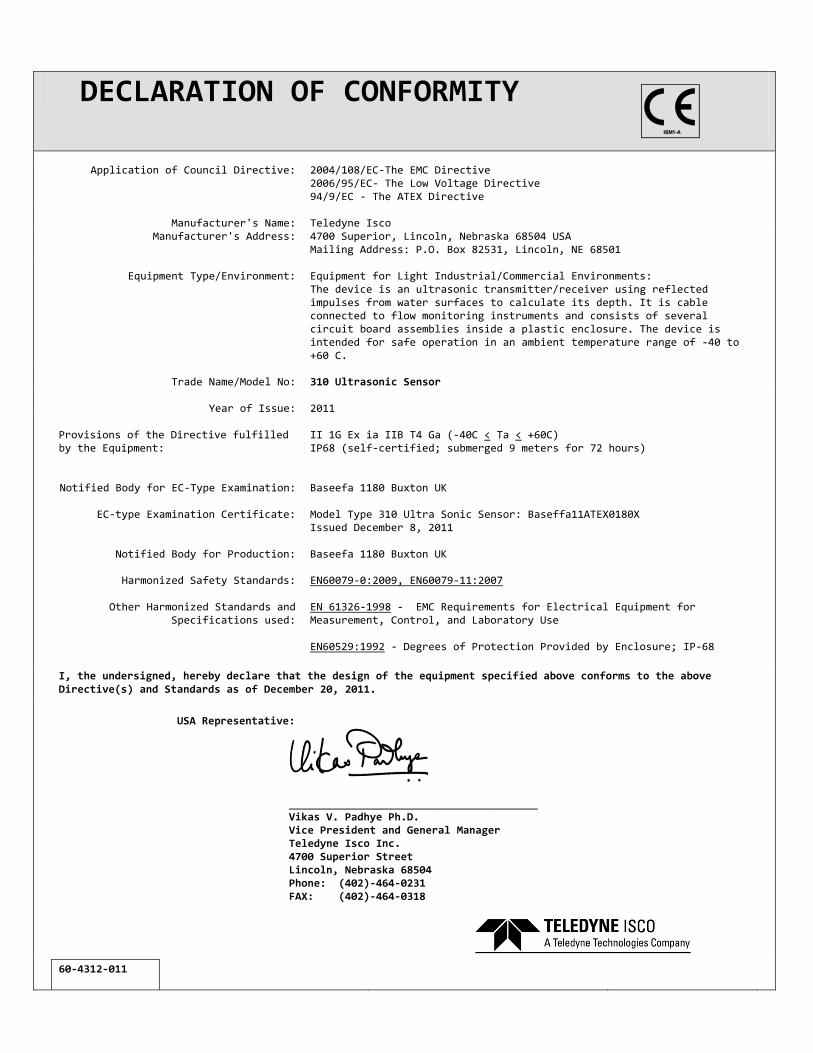
DECLARATION OF CONFORMITY
Application of Council Directive: 2004/108/EC-The EMC Directive 2006/95/EC- The Low Voltage Directive 94/9/EC - The ATEX Directive
Manufacturer's Name:
Teledyne Isco
Manufacturer's Address:
4700 Superior, Lincoln, Nebraska 68504 USA Mailing Address: P.O. Box 82531, Lincoln, NE 68501
Equipment Type/Environment:
Equipment for Light Industrial/Commercial Environments: The device is an ultrasonic transmitter/receiver using reflected impulses from water surfaces to calculate its depth. It is cable connected to flow monitoring instruments and consists of several circuit board assemblies inside a plastic enclosure. The device is intended for safe operation in an ambient temperature range of -40 to +60 C.
Trade Name/Model No:
310 Ultrasonic Sensor
Year of Issue:
2011
Provisions of the Directive fulfilled by the Equipment:
Notified Body for EC-Type Examination:
EC-type Examination Certificate:
Notified Body for Production:
Harmonized Safety Standards:
Other Harmonized Standards and Specifications used:
II 1G Ex ia IIB T4 Ga (-40C < Ta < +60C) IP68 (self-certified; submerged 9 meters for 72 hours) Baseefa 1180 Buxton UK Model Type 310 Ultra Sonic Sensor: Baseffa11ATEX0180X Issued December 8, 2011 Baseefa 1180 Buxton UK EN60079-0:2009, EN60079-11:2007 EN 61326-1998 - EMC Requirements for Electrical Equipment for Measurement, Control, and Laboratory Use EN60529:1992 - Degrees of Protection Provided by Enclosure; IP-68
I, the undersigned, hereby declare that the design of the equipment specified above conforms to the above Directive(s) and Standards as of December 20, 2011.
USA Representative:
________________________________________ Vikas V. Padhye Ph.D. Vice President and General Manager Teledyne Isco Inc. 4700 Superior Street Lincoln, Nebraska 68504 Phone: (402)-464-0231 FAX: (402)-464-0318
60-4312-011


Warranty
Before returning any instrument for repair, please call, fax, or e-mail the Teledyne Isco ServiceDepartment for instructions. Many problems can often be diagnosed and corrected over thephone, or by e-mail, without returning the instrument to the factory.Instruments needing factory repair should be packed carefully, and shipped to the attention ofthe service department. Small, non-fragile items can be sent by insured parcel post. PLEASEBE SURE TO ENCLOSE A NOTE EXPLAINING THE PROBLEM.
Shipping Address: Teledyne Isco - Attention Repair Service4700 Superior StreetLincoln, NE 68504 USA
Mailing Address: Teledyne IscoPO Box 82531Lincoln, NE 68501 USA
Phone: Repair service: (800) 775-2965 (lab instruments)(866) 298-6174 (samplers & flow meters)
Sales & General Information: (800) 228-4373 (USA & Canada)Fax: (402) 465-3001Email: [email protected]
October 11, 2013 P/N 60-1002-040 Rev H
Teledyne Isco One Year Limited Factory Service Warranty*This warranty exclusively covers Teledyne Isco
instruments, providing a one-year limited warranty
covering parts and labor.
Any instrument that fails during the warranty period due to
faulty parts or workmanship will be repaired at the factory
at no charge to the customer. Teledyne Isco�s exclusive
liability is limited to repair or replacement of defective
instruments. Teledyne Isco is not liable for consequential
damages.
Teledyne Isco will pay surface transportation charges both
ways within the 48 contiguous United States if the
instrument proves to be defective within 30 days of
shipment. Throughout the remainder of the warranty period,
the customer will pay to return the instrument to Teledyne
Isco, and Teledyne Isco will pay surface transportation to
return the repaired instrument to the customer. Teledyne
Isco will not pay air freight or customer�s packing and
crating charges. This warranty does not cover loss, damage,
or defects resulting from transportation between the
customer�s facility and the repair facility.
The warranty for any instrument is the one in effect on date
of shipment. The warranty period begins on the shipping
date, unless Teledyne Isco agrees in writing to a different
date.
Excluded from this warranty are normal wear; expendable
items such as pH sensors, charts, ribbon, lamps, tubing, and
glassware; fittings and wetted parts of valves; and damage
due to corrosion, misuse, accident, or lack of proper
maintenance. This warranty does not cover products not
sold under the Teledyne Isco trademark or for which any
other warranty is specifically stated.
No item may be returned for warranty service without a
return authorization number issued by Teledyne Isco.
This warranty is expressly in lieu of all other warranties
and obligations and Teledyne Isco specifically disclaims
any warranty of merchantability or fitness for a
particular purpose.
The warrantor is Teledyne Isco, 4700 Superior, Lincoln, NE
68504, U.S.A.
* This warranty applies to the USA and countries where Teledyne Isco does not have an authorized dealer.
Customers in countries outside the USA, where Teledyne Isco has an authorized dealer, should contact
their Teledyne Isco dealer for warranty service.