Tie-Up Wall Reconstruction Upper-Lock 3 (1)
14
Tie-up Wall Reconstruction, Upper- Lock 3 Benjamin Labrecque April 14, 2016
-
Upload
benjamin-labrecque -
Category
Documents
-
view
80 -
download
3
Transcript of Tie-Up Wall Reconstruction Upper-Lock 3 (1)
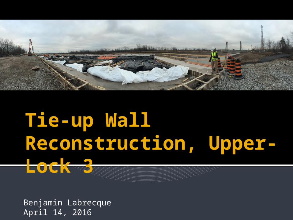
Tie-up Wall Reconstruction, Upper-Lock 3Benjamin LabrecqueApril 14, 2016
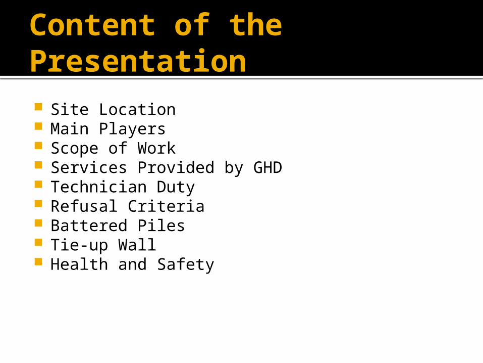
Content of the Presentation Site Location Main Players Scope of Work Services Provided by GHD Technician Duty Refusal Criteria Battered Piles Tie-up Wall Health and Safety

Site Location
Upper-Lock 3
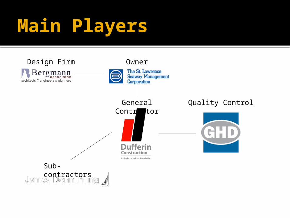
Main PlayersOwner
General Contractor
Quality Control
Sub-contractors
Design Firm
Scope of Work In 2013, SLSMC announced that $100 million will
be spent in the next four years (2013-2017) for Lock 1, 2, 3 replacement
Demolition and deconstruction of the existing tie-up walls, built in the 1960’s with timber piles
Design and construction of a new structure build with steel H-piles and concrete deck
Very restricted time period for construction Approximately a 12-week window to complete
the project before the Welland Canal was flooded back
Services Provided by GHD Quality Verification Engineer Services
Pile driving oversight Non-destructive welding inspection
Quality Control on site Reinforcing steel inspection Concrete inspection and testing Compaction quality control testing
Up to 11 inspectors were on site during piling operations and concrete pour
Technician Duty Pile driving monitoring
Record pile blow count for every foot driven in the ground
Ensure refusal criteria were achieved for every pile Hiley graphs
Concrete testing Perform slump test and air test Cast cylinders for lab cure and field cure
Welding inspection Visual inspection Ultrasonic testing

Refusal Criteria Every pile needed to
meet a design capacity of 3200 kN
PDA testing or Hiley graphs are two different ways to measure the bearing capacity of a pile
From the experience acquired in the past years, Bergmann decided to rely on Hiley graphs for approval
Refusal Criteria Graphs performed on the first 10 piles In order to facilitate and speed up piling
operations it was agreed that when a pile hit 10 Blows Per Inch (BPI) refusal was reached
To ensure that 10 BPI met the design capacity during the entire project, 1 Hiley graph was done for every 10 piles
Battered Piles Battered piles are driven with an angle (4:1) Provide a support for lateral loading Located on “F” line (closest to the wall) Design capacity of battered piles could not be
verified by a Hiley graph They had to be driven to the same depth as the
deeper of the two adjacent “D” row piles, unless 10 BPI was achieved
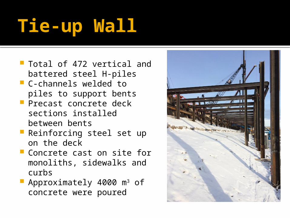
Tie-up Wall Total of 472 vertical and
battered steel H-piles C-channels welded to piles
to support bents Precast concrete deck
sections installed between bents
Reinforcing steel set up on the deck
Concrete cast on site for monoliths, sidewalks and curbs
Approximately 4000 m3 of concrete were poured
Tie-up Wall Piles driven to a wide range of depth Ground depth variating between 30 to 150 feet H-pile sections were originally 40 and 60-feet
long Splices Welding of a section onto another one could take
between 45 minutes to 2 hours
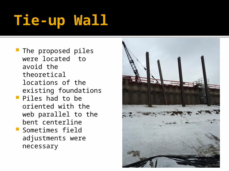
Tie-up Wall The proposed piles
were located to avoid the theoretical locations of the existing foundations
Piles had to be oriented with the web parallel to the bent centerline
Sometimes field adjustments were necessary
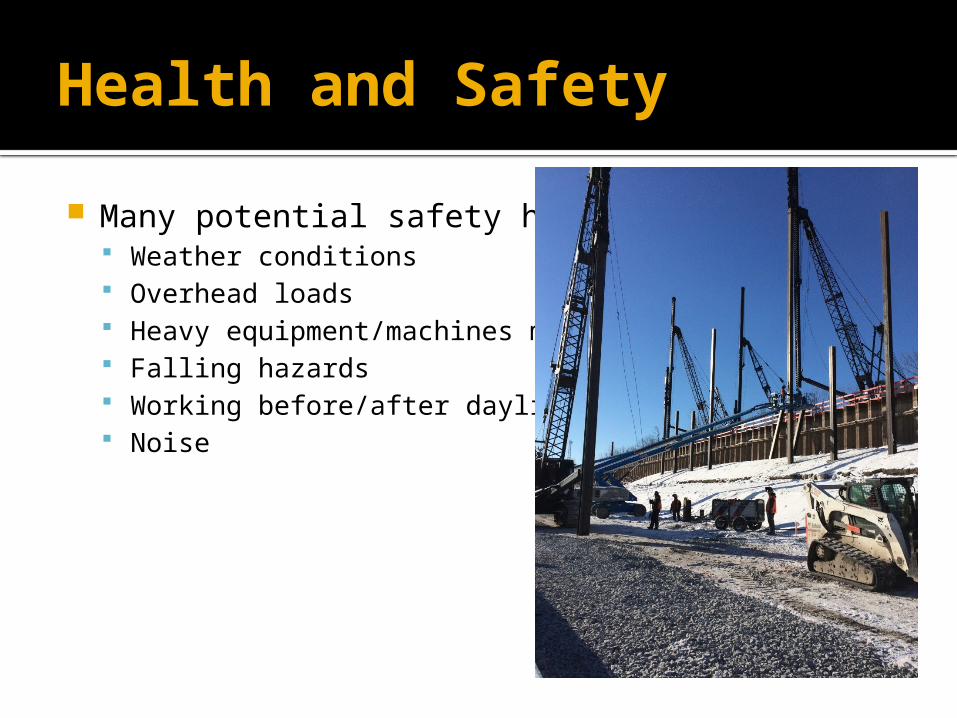
Health and Safety Many potential safety hazards
Weather conditions Overhead loads Heavy equipment/machines moving Falling hazards Working before/after daylight Noise