Tie Rod & Welded Cylinders Buyers Guide - Monarch … Piston Nut - Heavy duty, torqued, self locking...
20
Tie Rod & Welded Cylinders www.lionhydraulics.com Buyers Guide Fluid Power Products
Transcript of Tie Rod & Welded Cylinders Buyers Guide - Monarch … Piston Nut - Heavy duty, torqued, self locking...
Tie Rod & Welded Cylinders
www.lionhydraulics.com
Buyers Guide Fluid Power Products

Providing value engineered hydraulic solutions for todays demanding needs

3
Toll-Free 1-800-665-0247 | Phone (204) 786-7921 | Fax (204)889-9120
Table of Contents30 Month Warranty . . . . . . . . . . . . . . . . . . . . . . . . . . . . . . . . . . . . . . . . . . . . . . . .4
2500 TL Series Cylinders . . . . . . . . . . . . . . . . . . . . . . . . . . . . . . . . . . . . . . . . . . . .5
3000 TH Series Cylinders . . . . . . . . . . . . . . . . . . . . . . . . . . . . . . . . . . . . . . . . . . .8 3000 TP Rephasing Series . . . . . . . . . . . . . . . . . . . . . . . . . . . . . . . . . . . . . . . . .10 Hydraulic Stroke Control . . . . . . . . . . . . . . . . . . . . . . . . . . . . . . . . . . . . . . . . . .11
Dimensional Data Chart (TL, TH, TP) . . . . . . . . . . . . . . . . . . . . . . . . . . . . . . . . .12
Cylinder Sizing/Selection Information . . . . . . . . . . . . . . . . . . . . . . . . . . . . . . .13
WH Series Welded Cylinders . . . . . . . . . . . . . . . . . . . . . . . . . . . . . . . . . . . . . . .14 WX Series Welded Cylinders . . . . . . . . . . . . . . . . . . . . . . . . . . . . . . . . . . . . . . .16
Cylinder Accessories . . . . . . . . . . . . . . . . . . . . . . . . . . . . . . . . . . . . . . . . . . . . .18
Cylinder Repair Kits . . . . . . . . . . . . . . . . . . . . . . . . . . . . . . . . . . . . . . . . . . . . . .19
Toll-Free: 1-800-665-0247Phone: (204) 786-7921Fax: (204) 889-9120Fax Orders: (204) 772-9496
LION HYDRAULICS51 Burmac Road, P .O . Box 429,Winnipeg Manitoba, CanadaR3C 3E4www .lionhydraulics .com
Customer Service

4
www .lionhydraulics .com
TheFair
Exchange!
Guaranteed 30 Months*
Lion Hydraulic Cylinders are built tough enough to stand up to the roughest conditions - Tough enough that we now confidently offer this iron clad guarantee on every Lion Hydraulic Cylinder that we sell .
Should any Lion Hydraulic Cylinder fail due to quality of workmanship or materials within 30 months from the date of purchase, we will give you a new one absolutely free of charge.
* Bent, broken and rusted rods are not warrantable under this program.

5
Toll-Free 1-800-665-0247 | Phone (204) 786-7921 | Fax (204)889-9120
TL SERIES
1 Pins & Retainers - High tensile steel, zinc plated to prevent corrosion, comes with hair pin retainers .
2 Ports - Double ported NPTF for greater flexibility of assembly. Cylinders assembled with ports inline .
3 Piston Nut - Heavy duty, torqued, self locking piston nut holds piston in place under high cycle loading .
4 Piston - Ductile iron, precision machined providing a malleable bearing surface for extended cylinder life.
5 Piston Seal - 90 durometer o-ring with anti-extrusion back-up washers provide positive sealing under high load conditions .
2500 PSI Continuous Working Pressure5000 PSI Proof Pressure
6 Tie-Rods - High tensile steel to prevent failure under high pressure .
7 Cylinder Shaft - 1045 high strength steel, hard chrome plated shaft provides extended cylinder life in harsh applications .
8 Tube - Precision finished skive and burnished heavy wall steel tubing for extended seal and cylinder life.
9 Tube Seal - 90 durometer o-ring with anti-extrusion back-up washer to prevent leakage under high pressure and cycle loading .
10 Rod Seal - Polyurethane U-Cup providing long wearing, positive seal .
2 3 5 10 12 13 14
4 6 7 8 9 11
1
11 Rod Cap & Clevis Cap - Ductile iron comes with drilled oil passages, offering increased bearing surface for high shock and side load applications .
12 Rod Wiper - Heavy duty metal encased Nitrile, preventing contaminants from entering cylinder .
13 Threaded Shaft (on ASAE cylinders) - To accept optional mechanical stroke control, on 8” stroke ASAE cylinders only . NOTE: Not applicable to 5” bore cylinders .
14 Rod Clevis - Ductile iron comes with 360° thread contact area and positive set screw locking device able to withstand continuous high load without wear or fracture.
30 Month Fair Exchange Warranty
11

6
www .lionhydraulics .com
CYLINDER ORDERING INFORMATION - TL SERIES: ASAE & NON ASAE
Bore Stroke Rod Dia.
Order No. Model Pin to Pin Center Ship
Wt lbs. Pin Dia.Max. Rated PSI & Column
Load on Full ExtensionRetracted Extended PSI lbs.
ASA
E - T
L
2 .0" 8 .00 1 .13 639287 20TL08-112 ASAE 20 1/4 28 1/4 20 1” Full PSI 78542 .5" 8 .00 1 .13 639288 25TL08-112 ASAE 20 1/4 28 1/4 22 1” Full PSI 122723 .0" 8 .00 1 .25 639289 30TL08-125 ASAE 20 1/4 28 1/4 28 1” Full PSI 176723 .5" 8 .00 1 .25 639290 35TL08-125 ASAE 20 1/4 28 1/4 36 1” Full PSI 240534 .0" 8 .00 1 .25 639291 40TL08-125 ASAE 20 1/4 28 1/4 43 1” Full PSI 314165 .0" 8 .00 1 .50 639293 50TL08-150 ASAE 20 1/4 28 1/4 71 1” Full PSI 490883 .0" 16 .00 1 .50 639225 30TL16-150 ASAE 31 1/2 47 1/2 41 1 1/4” Full PSI 176723 .5" 16 .00 1 .50 639226 35TL16-150 ASAE 31 1/2 47 1/2 51 1 1/4” Full PSI 240534 .0" 16 .00 1 .75 639227 40TL16-175 ASAE 31 1/2 47 1/2 59 1 1/4” Full PSI 314165 .0" 16 .00 2 .00 639228 50TL16-200 ASAE 31 1/2 47 1/2 100 1 1/4” Full PSI 49088
ASAE - All Lion Hydraulic TL cylinders meet ASAE (American Society of Agricultural Engineers) specifications. These specifications establish common mounting i .e . (pin to pin dimensions) and clearance dimensions i .e . (clevis cap/rod clevis throat width and pin diameters) for cylinders and trailing-type agricultural implements . This criteria is only applicable to 8” and 16” stroke cylinders.
NOTE: All ASAE 2” through 4” bore cylinders with 8” stroke are designed with 20 1/4" retracted length to provide 2" additional threaded rod to accommodate a stroke control per ASAE Specifications.
NON ASAE - All Lion Hydraulics TL NON ASAE cylinders are designed per ASAE dimensional requirements, however do not include the additional 2" threaded rod length . Pin to pin dimensions are noted below .
*Cylinder Column Load: Column strength loading affects all long stroke cylinders. Affected cylinders should not be operated beyond these limits as the cylinder rod may buckle or bend causing failure. Pressure/load limitation applies to compressive (push) loading only. Ap-plications that fall outside the noted parameters, contact Lion Hydraulics directly for further assistance.
TL SERIES
Bore Stroke Rod Dia.
Order No. Model Pin to Pin Center Ship
Wt lbs. Pin Dia.Max. Rated PSI & Column
Load on Full ExtensionRetracted Extended PSI lbs.
NO
N A
SAE
- TL
2 .0"
4 .00 1 .13 639139 20TL04-112 14 1/4 18 1/4 17 1” Full PSI 78546 .00 1 .13 639140 20TL06-112 16 1/4 22 1/4 18 1” Full PSI 78548 .00 1 .13 639141 20TL08-112 18 1/4 26 1/4 19 1” Full PSI 7854
10 .00 1 .13 639142 20TL10-112 20 1/4 30 1/4 21 1” Full PSI 785412 .00 1 .13 639143 20TL12-112 22 1/4 34 1/4 22 1” Full PSI 785414 .00 1 .13 639144 20TL14-112 24 1/4 38 1/4 24 1” Full PSI 785416 .00 1 .13 639145 20TL16-112 26 1/4 42 1/4 25 1” Full PSI 785418 .00 1 .13 639146 20TL18-112 28 1/4 46 1/4 26 1” Full PSI 785420 .00 1 .13 639147 20TL20-112 30 1/4 50 1/4 28 1” Full PSI 785424 .00 1 .13 639148 20TL24-112 34 1/4 58 1/4 30 1” *2180 685030 .00 1 .13 639151 20TL30-112 40 1/4 70 1/4 34 1” *1500 470036 .00 1 .13 639152 20TL36-112 46 1/4 82 1/4 38 1” *1090 3430
2 .5"
4 .00 1 .13 639154 25TL04-112 14 1/4 18 1/4 18 1” Full PSI 122726 .00 1 .13 639155 25TL06-112 16 1/4 22 1/4 20 1” Full PSI 122728 .00 1 .13 639156 25TL08-112 18 1/4 26 1/4 21 1” Full PSI 12272
10 .00 1 .13 639157 25TL10-112 20 1/4 30 1/4 23 1” Full PSI 1227212 .00 1 .13 639158 25TL12-112 22 1/4 34 1/4 24 1” Full PSI 1227214 .00 1 .13 639159 25TL14-112 24 1/4 38 1/4 26 1” Full PSI 1227216 .00 1 .13 639160 25TL16-112 26 1/4 42 1/4 28 1” Full PSI 1227218 .00 1 .25 639161 25TL18-125 28 1/4 46 1/4 31 1” Full PSI 1227220 .00 1 .25 639162 25TL20-125 30 1/4 50 1/4 32 1” Full PSI 1227224 .00 1 .25 639163 25TL24-125 34 1/4 58 1/4 35 1” *2125 1043530 .00 1 .25 639165 25TL30-125 40 1/4 70 1/4 40 1” *1460 717536 .00 1 .25 639166 25TL36-125 46 1/4 82 1/4 45 1” *1065 5235
NOTE: * Indicates cylinder strength is affected, see notes above for details.
*1
7
Toll-Free 1-800-665-0247 | Phone (204) 786-7921 | Fax (204)889-9120
TL SERIES
Bore Stroke Rod Dia.
Order No. Model
Pin to Pin Center Retracted x Extended
Ship Wt lbs. Pin Dia.
Max. Rated PSI & Column Load on Full Extension
Retracted Extended PSI lbs.
NO
N A
SAE
- TL
3 .0"
4 .00 1 .25 639168 30TL04-125 14 1/4 18 1/4 23 1” Full PSI 176726 .00 1 .25 639169 30TL06-125 16 1/4 22 1/4 25 1” Full PSI 176728 .00 1 .25 639170 30TL08-125 18 1/4 26 1/4 27 1” Full PSI 17672
10 .00 1 .25 639171 30TL10-125 20 1/4 30 1/4 30 1” Full PSI 1767212 .00 1 .25 639172 30TL12-125 22 1/4 34 1/4 32 1” Full PSI 1767214 .00 1 .25 639173 30TL14-125 24 1/4 38 1/4 34 1” Full PSI 1767216 .00 1 .25 639174 30TL16-125 26 1/4 42 1/4 36 1” Full PSI 1767218 .00 1 .25 639175 30TL18-125 28 1/4 46 1/4 39 1” *2340 1656020 .00 1 .50 639176 30TL20-150 30 1/4 50 1/4 41 1” *1985 1402524 .00 1 .50 639177 30TL24-150 34 1/4 58 1/4 48 1” Full PSI 1767230 .00 1 .50 639179 30TL30-150 40 1/4 70 1/4 55 1” *2105 1488036 .00 1 .50 639180 30TL36-150 46 1/4 82 1/4 62 1” *1535 10855
3 .5"
4 .00 1 .25 639182 35TL04-125 14 1/4 18 1/4 30 1” Full PSI 240536 .00 1 .25 639183 35TL06-125 16 1/4 22 1/4 33 1” Full PSI 240538 .00 1 .25 639184 35TL08-125 18 1/4 26 1/4 35 1” Full PSI 24053
10 .00 1 .25 639185 35TL10-125 20 1/4 30 1/4 38 1” Full PSI 2405312 .00 1 .25 639186 35TL12-125 22 1/4 34 1/4 41 1” Full PSI 2405314 .00 1 .25 639187 35TL14-125 24 1/4 38 1/4 43 1” Full PSI 2405316 .00 1 .25 639188 35TL16-125 26 1/4 42 1/4 46 1” *2060 1984018 .00 1 .25 639189 35TL18-125 28 1/4 46 1/4 51 1” Full PSI 2405320 .00 1 .25 639190 35TL20-125 30 1/4 50 1/4 54 1” Full PSI 2405324 .00 1 .50 639191 35TL24-150 34 1/4 58 1/4 59 1” *2250 2164530 .00 1 .50 639193 35TL30-150 40 1/4 70 1/4 67 1” *1545 1488036 .00 1 .50 639194 35TL36-150 46 1/4 82 1/4 75 1” *1125 10850
4 .0"
4 .00 1 .25 639196 40TL04-125 14 1/4 18 1/4 37 1” Full PSI 314166 .00 1 .25 639197 40TL06-125 16 1/4 22 1/4 39 1” Full PSI 314168 .00 1 .25 639198 40TL08-125 18 1/4 26 1/4 42 1” Full PSI 31416
10 .00 1 .25 639199 40TL10-125 20 1/4 30 1/4 45 1” Full PSI 3141612 .00 1 .25 639201 40TL12-125 22 1/4 34 1/4 48 1” *2400 3019514 .00 1 .25 639202 40TL14-125 34 1/4 58 1/4 50 1” *1925 2421016 .00 1 .25 639203 40TL16-125 26 1/4 42 1/4 53 1” *1580 1984018 .00 1 .25 639204 40TL18-125 28 1/4 46 1/4 59 1” Full PSI 3141620 .00 1 .50 639205 40TL20-150 30 1/4 50 1/4 62 1” *2315 2908524 .00 1 .50 639206 40TL24-150 34 1/4 58 1/4 68 1” *1720 2164524 .00 1 .75 639207 40TL24-175 34 1/4 58 1/4 74 1” Full PSI 3141630 .00 2 .00 639208 40TL30-200 40 1/4 70 1/4 91 1” Full PSI 3141636 .00 2 .00 639209 40TL36-200 46 1/4 82 1/4 102 1” Full PSI 3141648 .00 2 .00 639210 40TL48-200 58 1/4 106 1/4 125 1” *1635 20560
5 .0"
10 .00 1 .50 639214 50TL10-150 22 1/4 32 1/4 75 1” Full PSI 4908812 .00 2 .00 639215 50TL12-200 24 1/4 36 1/4 87 1” Full PSI 4908814 .00 2 .00 639216 50TL14-200 26 1/4 40 1/4 92 1” Full PSI 4908816 .00 2 .00 639217 50TL16-200 28 1/4 44 1/4 96 1” Full PSI 4908818 .00 2 .00 639218 50TL18-200 30 1/4 48 1/4 101 1” Full PSI 4908820 .00 2 .00 639219 50TL20-200 32 1/4 52 1/4 106 1” Full PSI 4908824 .00 2 .00 639220 50TL24-200 36 1/4 60 1/4 116 1” Full PSI 4908830 .00 2 .00 639222 50TL30-200 42 1/4 72 1/4 131 1” *2265 4447036 .00 2 .00 639223 50TL36-200 48 1/4 84 1/4 145 1” *1665 32700
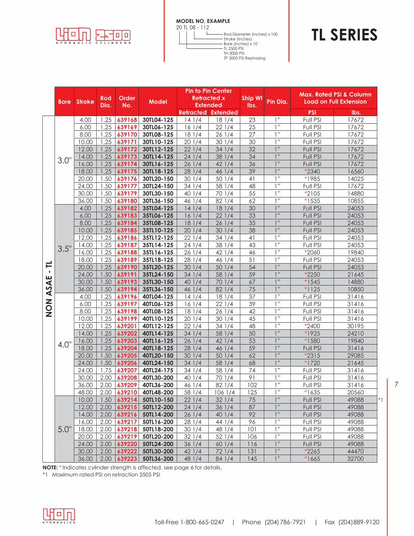
TL SERIES
NOTE: * Indicates cylinder strength is affected, see page 6 for details.
MODEL NO. EXAMPLE20 TL 08 - 112 Rod Diameter (inches) x 100 Stroke (inches) Bore (inches) x 10 TL 2500 PSI TH 3000 PSI TP 3000 PSI Rephasing
*1 Maximum rated PSI on retraction 2505 PSI
*1

8
www .lionhydraulics .com
11 Rod Seal - Polyurethane U-Cup pro-viding long wearing, positive seal .
12 Rod Cap & Clevis Cap - Ductile iron comes with drilled oil pas-sages, offering increased bear-ing surface for high shock and side load applications .
13 Rod Wiper - Heavy duty metal encased, nitrile preventing con-taminants from entering cylinder.
14 Threaded Shaft (on ASAE cyl-inders) - To accept optional mechanical stroke control
NOTE: Not applicable to ASAE 5" bore cylinders .
15 Rod Clevis - Ductile iron comes with 360° thread contact area and positive set screws locking device able to withstand con-tinuous high loads without wear or fracture.
1 Pins & Retainers - High tensile steel, zinc plated to prevent corrosion, comes with cotter pin retainers .
2 Ports - Double ported ORB for greater flexibility of assembly and positive sealing . Unless otherwise stated, cylinders assembled with ports inline .
3 Piston Nut - Heavy duty, torqued, self locking piston nut holds piston in place under high cycle loading .
4 Piston Wear Ring - 33% glass filled nylon wear ring incorporated in piston to provide side load bear-ing area, preventing scoring of cylinder tube .
5 Piston - Ductile iron, precision machined providing a malleable bearing surface for extended cylinder life.
6 Piston Seal - 15% fibre glass filled teflon piston seal comes with o-ring expander provides a positive piston seal with minimal friction, extending seal operation under high pressure applications .
7 Tie-Rods - High tensile steel to pre-vent failure under high pressure.
8 Cylinder Shaft - 1045 high strength steel, hard chrome plated shaft provides extended cylinder life in harsh applications.
9 Tube - Precision finished skive and burnished heavy wall steel tubing for extended seal and cylinder life.
10 Tube Seal - 90 durometer o-ring with anti-extrusion back-up washer to prevent leakage under high pressure and cycle loading .
1 2
3
5
12
11
12
134 6
7 8 9 10
14 15
TH SERIES 3000 PSI Continuous Working Pressure6000 PSI Proof Pressure
30 Month Fair Exchange Warranty

9
Toll-Free 1-800-665-0247 | Phone (204) 786-7921 | Fax (204)889-9120
CYLINDER ORDERING INFORMATION - TH SERIES: ASAE & NON ASAE
Bore Stroke Rod Dia.
Order No. Model Pin to Pin Center Ship
Wt lbs.
Pin Dia.
Max. Rated PSI & Column Load on Full Extension
Extended PSI lbs.A
SAE
- TH
2 .0" 8 .00 1 .13 639280 20TH08-112 ASAE 20 1/4 28 1/4 20 1” Full PSI 94252 .5" 8 .00 1 .13 639281 25TH08-112 ASAE 20 1/4 28 1/4 22 1” Full PSI 147263 .0" 8 .00 1 .25 639282 30TH08-125 ASAE 20 1/4 28 1/4 28 1” Full PSI 212063 .5" 8 .00 1 .25 639283 35TH08-125 ASAE 20 1/4 28 1/4 36 1” Full PSI 288634 .0" 8 .00 1 .37 639284 40TH08-137 ASAE 20 1/4 28 1/4 44 1” Full PSI 376995 .0" 8 .00 2 .00 639286 50TH08-200 ASAE 20 1/4 28 1/4 78 1 1/4” Full PSI 589053 .0" 16 .00 1 .50 639699 30TH16-150 ASAE 31 1/2 47 1/2 41 1 1/4” Full PSI 212063 .5" 16 .00 1 .50 639700 35TH16-150 ASAE 31 1/2 47 1/2 51 1 1/4” Full PSI 288634 .0" 16 .00 1 .75 639701 40TH16-175 ASAE 31 1/2 47 1/2 64 1 1/4” Full PSI 376995 .0" 16 .00 2 .00 639702 50TH16-200 ASAE 31 1/2 47 1/2 100 1 1/4” Full PSI 58905
NOTE: All 2" through 4" bore cylinders with 8" stroke are designed with rod threaded to accommodate a stroke control collar per ASAE specifications. (See page 6 definition)
Bore Stroke Rod Dia.
Order No. Model Pin to Pin Center Ship Wt
lbs.Pin Dia.
Max. Rated PSI & Column Load on Full Extension
Retracted Extended PSI lbs.
NO
N A
SAE
- TH
2 .0"
8 .00 1 .13 639617 20TH08-112 18 1/4 26 1/4 19 1” Full PSI 942510 .00 1 .13 639618 20TH10-112 20 1/4 30 1/4 21 1” Full PSI 942512 .00 1 .13 639619 20TH12-112 22 1/4 34 1/4 22 1” Full PSI 942514 .00 1 .13 639620 20TH14-112 24 1/4 38 1/4 24 1” Full PSI 942516 .00 1 .13 639621 20TH16-112 26 1/4 42 1/4 25 1” Full PSI 942518 .00 1 .13 639622 20TH18-112 28 1/4 46 1/4 26 1” Full PSI 942520 .00 1 .13 639623 20TH20-112 30 1/4 50 1/4 28 1” *2930 920524 .00 1 .13 639624 20TH24-112 34 1/4 58 1/4 30 1” *2180 6850
2 .5"
8 .00 1 .13 639631 25TH08-112 18 1/4 26 1/4 21 1” Full PSI 1472610 .00 1 .13 639632 25TH10-112 20 1/4 30 1/4 23 1” Full PSI 1472612 .00 1 .13 639633 25TH12-112 22 1/4 34 1/4 24 1” Full PSI 1472614 .00 1 .13 639634 25TH14-112 24 1/4 38 1/4 26 1” Full PSI 1472616 .00 1 .25 639635 25TH16-125 26 1/4 42 1/4 29 1” Full PSI 1472618 .00 1 .25 639636 25TH18-125 28 1/4 46 1/4 31 1” Full PSI 1472620 .00 1 .25 639637 25TH20-125 30 1/4 50 1/4 32 1” *2855 1402524 .00 1 .25 639638 25TH24-125 34 1/4 58 1/4 35 1” *2125 10435
3 .0"
8 .00 1 .25 639645 30TH08-125 18 1/4 26 1/4 27 1” Full PSI 2120610 .00 1 .25 639646 30TH10-125 20 1/4 30 1/4 30 1” Full PSI 2120612 .00 1 .25 639647 30TH12-125 22 1/4 34 1/4 32 1” Full PSI 2120614 .00 1 .25 639648 30TH14-125 24 1/4 38 1/4 35 1” Full PSI 2120616 .00 1 .50 639649 30TH16-150 26 1/4 42 1/4 39 1” Full PSI 2120618 .00 1 .50 639650 30TH18-150 28 1/4 46 1/4 41 1” Full PSI 2120620 .00 1 .50 639651 30TH20-150 30 1/4 50 1/4 43 1” Full PSI 2120624 .00 1 .50 639652 30TH24-150 34 1/4 58 1/4 48 1” Full PSI 21206
3 .5"
8 .00 1 .25 639659 35TH08-125 18 1/4 26 1/4 35 1” Full PSI 2886310 .00 1 .25 639660 35TH10-125 20 1/4 30 1/4 38 1” Full PSI 2886312 .00 1 .25 639661 35TH12-125 22 1/4 34 1/4 41 1” Full PSI 2886314 .00 1 .25 639662 35TH14-125 24 1/4 38 1/4 43 1” Full PSI 2886316 .00 1 .50 639663 35TH16-150 26 1/4 42 1/4 48 1” Full PSI 2886318 .00 1 .50 639664 35TH18-150 28 1/4 46 1/4 51 1” Full PSI 2886320 .00 1 .50 639665 35TH20-150 30 1/4 50 1/4 54 1” Full PSI 2886324 .00 1 .50 639666 35TH24-150 34 1/4 58 1/4 59 1” *2250 21645
4 .0"
8 .00 1 .37 639673 40TH08-137 18 1/4 26 1/4 43 1” Full PSI 3769910 .00 1 .37 639674 40TH10-137 20 1/4 30 1/4 46 1” Full PSI 3769912 .00 1 .37 639675 40TH12-137 22 1/4 34 1/4 48 1” Full PSI 3769914 .00 1 .37 639676 40TH14-137 24 1/4 38 1/4 52 1” Full PSI 3769916 .00 1 .75 639677 40TH16-175 26 1/4 42 1/4 61 1” Full PSI 3769918 .00 1 .75 639678 40TH18-175 28 1/4 46 1/4 64 1” Full PSI 3769920 .00 1 .75 639679 40TH20-175 30 1/4 50 1/4 67 1” Full PSI 3769924 .00 1 .75 639680 40TH24-175 34 1/4 58 1/4 74 1” Full PSI 37699
5 .0"
10 .00 2 .00 639688 50TH10-200 22 1/4 32 1/4 78 1 1/4” Full PSI 5890512 .00 2 .00 639689 50TH12-200 24 1/4 36 1/4 88 1 1/4” Full PSI 5890514 .00 2 .00 639690 50TH14-200 26 1/4 40 1/4 93 1 1/4” Full PSI 5890516 .00 2 .00 639691 50TH16-200 28 1/4 44 1/4 97 1 1/4” Full PSI 5890518 .00 2 .00 639692 50TH18-200 30 1/4 48 1/4 102 1 1/4” Full PSI 5890520 .00 2 .00 639693 50TH20-200 32 1/4 52 1/4 107 1 1/4” Full PSI 5890524 .00 2 .00 639694 50TH24-200 36 1/4 60 1/4 117 1 1/4” Full PSI 58905
NOTE: * Indicates cylinder strength is affected, see page 6 for details.

10
www .lionhydraulics .com
3 Push Rod - Provides positive actuation of spool valve and eliminates the need for additional hydraulic tub-ing and fittings. (NOTE: Push rod length is propor-tional to cylinder stroke).
4 Actuator - Ductile iron, allowing for infinite control of cylinder stroke by adjusting actuator position on shaft. Aluminum bushing prevents damage to cylinder shaft.
1 Pins & Retainers - High tensile steel, zinc plated to prevent corrosion, comes with cotter pin retainers .
2 Ports - Double ported ORB for greater flexibility of assembly and positive sealing .Cylinders as-sembled with ports inline .
3 Piston Nut - Heavy duty, torqued, self locking piston nut holds piston in place under high cycle loading .
4 Piston Wear Ring - 33% glass filled nylon wear ring incorporated in piston to provide side load bear-ing area, preventing scoring of cylinder tube .
5 Piston - Ductile iron, precision machined providing a mallea-ble bearing surface for extend-ed cylinder life.
6 Piston Seal - 15% fibre glass filled teflon piston seal comes with o-ring expander provides a positive
1 Valve Body - Precision machined with flexible 3/4 - 16 coupler for ease of assembly, to base end port of cylinder body .
2 Spool Valve - Stainless steel to eliminate corrosion, "nyla-tron" piston for extended life.
HYDRAULIC STROKE CONTROL ASSEMBLY
TP REPHASING SERIES
piston seal with minimal friction, extending seal operation under high pressure applications .
7 Tie-Rods - High tensile steel with rolled threads to prevent failure under high pressure .
8 Cylinder Shaft - 1045 high strength steel, hard chrome plated shaft provides extended cylinder life in harsh applications.
9 Tube - Precision finished skive and burnished heavy wall steel tubing for extended seal and cylinder life.
10 Bypass Port - Precision machined and finished bypass port to ensure positive rephasing of cylinders with minimal settleback and consistent rephasing flow.
11 Tube Seal - 90 durometer o-ring with anti-extrusion back-up wash-er to prevent leakage under high pressure and cycle loading .
NOTE: Hydraulic Stroke Control Assembly assembled to rephasing cylinder for picto-rial purposes only, it is available separately, see page 11 for order numbers.
3 127 8 9
1
2 5
10
11 134 6 14 15 16
1 2 3 4
12 Rod Seal - Polyurethane U-Cup providing long wearing, positive seal .
13 Rod Cap & Clevis Cap - Ductile iron comes with drilled oil pas-sages, offering increased bear-ing surface for high shock and side load applications .
14 Rod Wiper - Heavy duty metal encased, nitrile preventing contaminants from entering cylinder .
15 Threaded Shaft (on ASAE cylinders) To accept optional mechanical stroke control.
NOTE: Not applicable to ASAE 5" bore cylinders .
16 Rod Clevis - Ductile iron comes with 360° thread contact area and positive set screws locking device able to withstand con-tinuous high loads without wear or fracture.
30 Month Fair Exchange Warranty
3000 PSI Continuous Working Pressure6000 PSI Proof Pressure

11
Toll-Free 1-800-665-0247 | Phone (204) 786-7921 | Fax (204)889-9120
ASAE REPHASING CYLINDERS
REPHASING CYLINDER SYSTEMS (TP SERIES)
A Hydraulic Stroke Control Asembly mounted on a TP or TH Series cylinder can provide an infinitely variable stroke adjustment for that cylinder .
HYDRAULIC STROKE CONTROL ASSEMBLY
TP REPHASING SERIES
Bore Stroke Rod Dia. Order No. Model Pin to Pin Center Ship Wt
lbs.Pin Dia.
Max. Rated PSI & Column Load on Full Extension
Retracted Extemded PSI lbs.2 .5" 8 .00 1 .13 639703 25TP08-112 20 1/4 28 1/4 22 1” Full PSI 147262 .7" 8 .00 1 .13 639704 27TP08-112 20 1/4 28 1/4 25 1” Full PSI 178193 .0" 8 .00 1 .25 639705 30TP08-125 20 1/4 28 1/4 28 1” Full PSI 212063 .2" 8 .00 1 .25 639706 32TP08-125 20 1/4 28 1/4 32 1” Full PSI 248873 .5" 8 .00 1 .25 639707 35TP08-125 20 1/4 28 1/4 36 1” Full PSI 288633 .7" 8 .00 1 .37 639708 37TP08-137 20 1/4 28 1/4 42 1” Full PSI 331344 .0" 8 .00 1 .37 639709 40TP08-137 20 1/4 28 1/4 44 1” Full PSI 376994 .2" 8 .00 1 .50 639710 42TP08-150 20 1/4 28 1/4 50 1” Full PSI 425594 .5" 8 .00 1 .50 639711 45TP08-150 20 1/4 28 1/4 52 1” Full PSI 477134 .7" 8 .00 1 .50 639712 47TP08-150 20 1/4 28 1/4 70 1” Full PSI 531625 .0" 8 .00 1 .50 639713 50TP08-150 20 1/4 28 1/4 72 1” Full PSI 58905
NOTE: All 2 1/2" through 4 1/2" bore cylinders with 8" stroke are designed with the rod threaded to accomodate a stroke control collar per ASAE specifications. (See page 6 definition)*1 Maximum rated PSI on retraction 2805 PSI*2 Maximum rated PSI on retraction 2505 PSI
Synchronized operation of two or more hydraulic cylinders in unbalanced load conditions can be attained by plumbing volu-metrically matched cylinders (see specific cylinder bore and shaft diameters on accompanying TP Series chart) adjacent to each other where the displaced fluid
produces, equal, simultaneous, actuation of each cylinder in the system. As the volumes of each cylinder cannot economically, be identically matched, a bypass port is provided that upon full extension (or retraction) a metered amount of fluid bypasses the piston seal to the next adjacent cylinder in the
system. This indexes all cylinders of the system to the sames position, then upon retraction (extension) positive sealing is engaged and sychronized operation continues (to ensure optimum performance all entrapped air must be purged from these rephasing cylinder systems) .
Model No. Order No. Rod DIa. Ship Wt lbs. Used onHSC-2730 637290 1 1/8 - 1 1/4 3 .0 2 .75" - 3 .00" Bore SeriesHSC-3235 637291 1 1/4 3 .0 3 .25" - 3 .50" Bore SeriesHSC-3740 637292 1 3/8 3 .5 3 .75" - 4 .00" Bore SeriesHSC-4245 637293 1 1/2 4 .0 4 .25" - 4 .50" Bore SeriesHSC-4750 637294 1 1/2 4 .0 4 .75" - 5 .00" Bore Series
HYDRAULIC STROKE CONTROL (APPLICABLE TO TP & TH SERIES)When used in conjunction with the master cylinder of a rephas-ing system, it provides consistent positive stroke control of the entire system .
NOTE: The hydraulic stroke control assembly is designed to mount on 8" stroke ASAE cylinders. Additional modification to push rod length is required for mounting on all other cylinder sizes .
*1*2

12
www .lionhydraulics .com
NOTE: Rod Clevis Threads are UNF -- NOTE: PTl = NPTF Ports - PTH = 3/4-16 UNF ORB Ports - PTP = 3/4-16 UNF ORB Ports
DIMENSIONS FOR 2500 PSI (TL); 3000 PSI (TH); REPHASING (TP); DIMENSIONS IN INCHES
TL, TH, TP CYLINDERSDIMENSIONAL DATA
/
Bore 2.00" 2.50" 2.75" 3.00" 3.25" 3.50" 3.75" 4.00" 4.25" 4.50" 4.75" 5.00"A 10 1/4 10 1/4 10 1/4 10 1/4 10 1/4 10 1/4 10 1/4 10 1/4 10 1/4 10 1/4 12 1/4 12 1/4B 2 1/8 2 1/8 2 1/8 2 1/8 2 1/8 2 1/8 2 1/8 2 1/8 2 1/8 2 1/8 2 1/8 2 1/8B1 4 3/16 4 3/16 3 15/16 3 15/16 3 15/16 3 15/16 3 7/8 3 7/8 3 7/8 3 7/8 4 11/16 4 11/16C 2 1/16 2 1/16 2 1/16 2 1/16 2 1/16 2 1/16 2 1/16 2 1/16 2 1/16 2 1/16 2 1/4 2 1/4D 2 7/8 2 7/8 2 3/4 2 3/4 2 3/4 2 3/4 2 3/4 2 3/4 2 3/4 2 3/4 2 7/8 2 7/8E 2 3/4 3 1/8 3 3/4 3 3/4 4 1/2 4 1/2 5 1/8 5 1/8 5 1/4 5 1/4 6 6F 1 3/8 1 9/16 1 7/8 1 7/8 2 1/4 2 1/4 2 9/16 2 9/16 2 5/8 2 5/8 3 3G 1 1/8 1 1/8 1 1/8 1 1/8 1 1/8 1 1/8 1 1/8 1 1/8 1 3/16 1 3/16 1 3/16 1 3/16G1 1 1/8 1 1/8 1 1/8 1 1/8 1 1/8 1 1/8 1 1/8 1 1/8 1 1/8 1 1/8 1 5/16 1 5/16H 2 1/2 2 1/2 2 1/2 2 5/8 2 5/8 2 5/8 2 5/8 2 5/8 3 3 3 3H1 2 3/8 2 1/2 2 9/16 2 9/16 2 9/16 2 9/16 2 5/8 2 5/8 3 3 3 1/2 3 1/2J 1 1 1 1 1/8 1 1/8 1 1/8 1 1/8 1 1/8 1 5/16 1 5/16 1 5/16 1 5/16J1 1 1 1 1 1 1/8 1 1/8 1 1/8 1 1/8 1 1/8 1 1/8 1 7/16 1 7/16KTl 1 1/64 1 1/64 N/A 1 1/64 N/A 1 1/64 N/A 1 1/64 N/A 1 1/64 N/A 1 1/64KTH 1 1/64 1 1/64 N/A 1 1/64 N/A 1 1/64 N/A 1 1/64 N/A N/A N/A 1 17/64KTP 1 1/64 1 1/64 1 1/64 1 1/64 1 1/64 1 1/64 1 1/64 1 1/64 1 1/64 1 1/64 1 1/64 1 1/64
M 1 1/8- 12
1 1/8- 12
1 1/8- 12
1 1/4- 12
1 1/4- 12
1 1/4- 12
1 1/4- 12
1 1/4- 12
1 1/2- 12
1 1/2- 12
1 1/2- 12
1 1/2- 12
PTl 3/8 3/8 N/A 1/2 N/A 1/2 N/A 1/2 N/A 1/2 N/A 1/2PTH 3/4-16 3/4-16 N/A 3/4-16 N/A 3/4-16 N/A 3/4-16 N/A 3/4-16 N/A 3/4-16PTP 3/4-16 3/4-16 3/4-16 3/4-16 3/4-16 3/4-16 3/4-16 3/4-16 3/4-16 3/4-16 3/4-16 3/4-16T 3/8 3/8 1/2 1/2 5/8 5/8 5/8 5/8 5/8 5/8 3/4 3/4
ASAE CYLINDERSA ASAE-8
12 1/4 12 1/4 12 1/4 12 1/4 12 1/4 12 1/4 12 1/4 12 1/4 12 1/4 12 1/4 12 1/4 12 1/4
A ASAE-16
15 1/2 15 1/2 15 1/2 15 1/2 15 1/2 15 1/2 15 1/2 15 1/2 15 1/2 15 1/2 15 1/2 15 1/2
B1 ASAE-8
6 3/16 6 3/16 5 15/16 5 15/16 5 15/16 5 15/16 5 7/8 5 7/8 5 5/8 5 5/8 4 11/16 4 11/16
B1 ASAE-16
9 7/16 9 7/16 9 3/16 9 3/16 9 3/16 9 3/16 9 1/8 9 1/8 8 7/8 8 7/8 7 15/16 7 15/16
K ASAE-8
1 1/64 1 1/64 1 1/64 1 1/64 1 1/64 1 1/64 1 1/64 1 1/64 1 1/64 1 1/64 1 1/64 1 1/64
K ASAE-16
1 17/64 1 17/64 1 17/64 1 17/64 1 17/64 1 17/64 1 17/64 1 17/64 1 17/64 1 17/64 1 17/64 1 17/64
13
Toll-Free 1-800-665-0247 | Phone (204) 786-7921 | Fax (204)889-9120
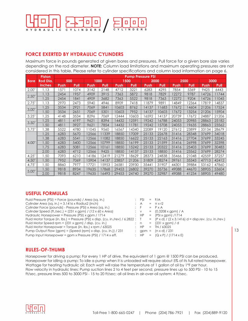
USEFUL FORMULASFluid Pressure (PSI) = Force (pounds) / Area (sq. in.) : PSI = F/ACylinder Area (sq. in.) = 3.1416 x Radius2 (inch) : A = π x r2Cylinder Force (pounds) - Pressure (PSI) x Area (sq. in.) : F = P x ACylinder Speed (ft./sec.) = (231 x gpm) / (12 x 60 x Area) : v = (0.3208 x gpm) / AHydraulic Horsepower = Pressure (PSI) x gpm / 1714 : HP = (PSI x gpm) /1714Fluid Motor Torque (in. lbs.) = Pressure (PSI) x disp . (cu . in ./rev) / 6 .2822 : T = (P x d) / (2 x 3 .1416) d = disp .rev . (cu . in ./rev .)Fluid Motor Speed rpm = (231 x gpm) / disp . (cu . in .) : n = (231 x gpm) / dFluid Motor Horsepower = Torque (in. lbs.) x rpm / 63025 : HP = TN / 63025Pump Output Flow (gpm) = (Speed (rpm) x disp . (cu . in .)) / 231 : gpm = (n x d) / 231Pump Input Horsepower = gpm x Pressure (PSI) / 1714 x eff. : HP = (Q x P) / (1714 x E)
RULES-OF-THUMBHorsepower for driving a pump: For every 1 HP of drive, the equivalent of 1 gpm @ 1500 PSI can be produced .Horsepower for idling a pump: To idle a pump when it is unloaded will require about 5% of its full rated horsepower.Wattage for heating hydraulic oil: Each watt will raise the temperature of 1 gallon of oil by 1°F per hour.Flow velocity in hydraulic lines: Pump suction lines 2 to 4 feet per second, pressure lines up to 500 PSI - 10 to 15 ft/sec, pressure lines 500 to 3000 PSI - 15 to 20 ft/sec; all oil lines in air-over-oil system: 4 ft/sec.
FORCE EXERTED BY HYDRAULIC CYLINDERSMaximum force in pounds generated at given bores and pressures. Pull force for a given bore size varies depending on the rod diameter . NOTE: Column load limitations and maximum operating pressures are not considered in this table. Please refer to cylinder specifications and column load information on page 6.
BorePiston
Rod Dia. inches
Pump Pressure PSI500 1000 1500 2000 2500 3000
Push Pull Push Pull Push Pull Push Pull Push Pull Push Pull2 .00" 1 .13 1571 1074 3142 2148 4712 3221 6283 4295 7854 5369 9425 6443
2 .50" 1 .13 2454 1957 4909 3915 7363 5872 9818 7829 12272 9787 14726 117441 .25 2454 1841 4909 3682 7363 5522 9818 7363 12272 9204 14726 11045
2 .75" 1 .13 2970 2473 5940 4946 8909 7418 11879 9891 14849 12364 17819 14837
3 .00" 1 .25 3534 2921 7069 5841 10603 8762 14137 11683 17672 14604 21206 175241 .50 3534 2651 7069 5301 10603 7952 14137 10603 17672 13254 21206 15904
3 .25" 1 .25 4148 3534 8296 7069 12444 10603 16592 14137 20739 17672 24887 21206
3 .50" 1 .25 4811 4197 9621 8394 14432 12591 19242 16788 24053 20985 28863 251821 .50 4811 3927 9621 7854 14432 11781 19242 15708 24053 19635 28863 23562
3 .75" 1 .38 5522 4780 11045 9560 16567 14340 22089 19120 27612 23899 33134 28679
4 .00"
1 .25 6283 5670 12566 11339 18850 17009 25133 22678 31416 28348 37699 340181 .38 6283 5541 12566 11082 18850 16622 25133 22163 31416 27704 37699 332451 .50 6283 5400 12566 10799 18850 16199 25133 21599 31416 26998 37699 323981 .75 6283 5081 12566 10161 18850 15242 25133 20322 31416 25403 37699 304832 .00 6283 4712 12566 9425 18850 14137 25133 18850 31416 23562 37699 28274
4 .25" 1 .50 7093 6210 14186 12419 21279 18629 28373 24838 35466 21048 42559 372574 .50" 1 .50 7952 7069 15904 14137 23857 21206 31809 28274 39761 35343 47713 424124 .75" 1 .50 8860 7977 17721 15953 26581 23930 35441 31907 44301 39884 53162 47860
5 .00" 1 .50 9818 8934 19635 17868 29453 26802 39270 35736 49088 44670 58905 536042 .00 9818 8247 19635 16493 29453 24740 39270 32987 49088 41234 58905 49480
/
14
www .lionhydraulics .com
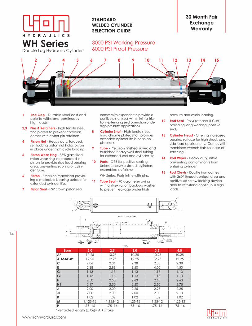
Bore 2.0 2.5 3.0 3.5 4.0A* 10 .25 10 .25 10 .25 10 .25 10 .25A ASAE-8* 12 .25 12 .25 12 .25 12 .25 12 .25C 2 .06 2 .06 2 .38 2 .38 2 .38E 2 .38 2 .88 3 .50 4 .00 4 .50G 1 .13 1 .13 1 .13 1 .13 1 .13G1 1 .13 1 .13 1 .13 1 .13 1 .13H 2 .50 2 .50 2 .63 2 .63 2 .63H1 2 .17 2 .50 2 .50 2 .50 2 .75J 2 .00 2 .00 2 .25 2 .25 2 .25J1 2 .00 2 .00 2 .00 2 .00 2 .13K 1 .02 1 .02 1 .02 1 .02 1 .02M 1 .125-12 1 .125-12 1 .25-12 1 .25-12 1 .25-12P .75 -16 .75 -16 .75 -16 .75 -16 .75 -16
*Retracted length (± .06)= A + stroke
WH Series Double Lug Hydraulic Cylinders
1 2 3 4 5 6 7 8 9 10 11 12 13 14 15
3000 PSI Working Pressure6000 PSI Proof Pressure
1 End Cap - Durable steel cast end able to withstand continuous high loads .
2,3 Pins & Retainers - High tensile steel, zinc plated to prevent corrosion, comes with cotter pin retainers .
4 Piston Nut - Heavy duty, torqued, self locking piston nut holds piston in place under high cycle loading .
5 Piston Wear Ring - 33% glass filled nylon wear ring incorporated in piston to provide side load bearing area, preventing scoring of cylin-der tube .
6 Piston - Precision machined provid-ing a malleable bearing surface for extended cylinder life.
7 Piston Seal - PSP crown piston seal
comes with expander to provide a positive piston seal with minimal fric-tion, extending seal operation under high pressure applications .
8 Cylinder Shaft - High tensile steel, hard chrome plated shaft provides extended cylinder life in harsh ap-plications .
9 Tube - Precision finished skived and burnished heavy wall steel tubing for extended seal and cylinder life.
10 Ports - ORB for positive sealing. Unless otherwise stated, cylinders assembled as follows:
WH Series: Ports inline with pins .
11 Tube Seal - 90 durometer o-ring with anti-extrusion back-up washer to prevent leakage under high
pressure and cycle loading .
12 Rod Seal - Polyurethane U-Cup providing long wearing, positive seal .
13 Cylinder Head - Offering increased bearing surface for high shock and side load applications . Comes with machined wrench flats for ease of servicing .
14 Rod Wiper - Heavy duty, nitrile preventing contaminants from entering cylinder .
15 Rod Clevis - Ductile iron comes with 360° thread contact area and positive set screw locking device able to withstand continuous high loads .
30 Month Fair Exchange Warranty
STANDARD WELDED CYLINDER SELECTION GUIDE

15
Toll-Free 1-800-665-0247 | Phone (204) 786-7921 | Fax (204)889-9120
WH Series Double Lug Hydraulic Cylinders
WH
SERI
ES
Bore Stroke Rod Dia.
Order No. Model
Pin to Pin Center Ship Wt lbs. Pin Dia
Max Rated PSI & Column Load on Full Extension
Retracted Extended PSI lbs.
2"
8 .00 1 .13 644800 20WH08-112 18 1/4 26 1/4 16 1" 3000 94258 .00 1 .13 644808 20WH08-112 ASAE 20 1/4 28 1/4 16 1" 3000 9425
10 .00 1 .13 644801 20WH10-112 20 1/4 30 1/4 17 1" 3000 942512 .00 1 .13 644802 20WH12-112 22 1/4 24 1/4 18 1" 3000 942514 .00 1 .13 644803 20WH14-112 24 1/4 38 1/4 20 1" 3000 942516 .00 1 .13 644804 20WH16-112 26 1/4 42 1/4 21 1" 3000 942518 .00 1 .13 644805 20WH18-112 28 1/4 46 1/4 22 1" 3000 942520 .00 1 .13 644806 20WH20-112 30 1/4 50 1/4 24 1" *2930 920424 .00 1 .13 644807 20WH24-112 34 1/4 58 1/4 26 1" *2180 6849
2 .5"
8 .00 1 .13 644810 25WH08-112 18 1/4 26 1/4 19 1" 3000 147268 .00 1 .13 644818 25WH08-112 ASAE 20 1/4 28 1/4 20 1" 3000 14726
10 .00 1 .13 644811 25WH10-112 20 1/4 30 1/4 21 1" 3000 1472612 .00 1 .13 644812 25WH12-112 22 1/4 34 1/4 22 1" 3000 1472614 .00 1 .13 644813 25WH14-112 24 1/4 38 1/4 24 1" 3000 1472616 .00 1 .25 644814 25WH16-125 26 1/4 42 1/4 26 1" 3000 1472618 .00 1 .25 644815 25WH18-125 28 1/4 46 1/4 28 1" 3000 1472620 .00 1 .25 644816 25WH20-125 30 1/4 50 1/4 29 1" *2855 1401424 .00 1 .25 644817 25WH24-125 34 1/4 58 1/4 33 1" *2125 10431
3"
8 .00 1 .25 644820 30WH08-125 18 1/4 26 1/4 26 1" 3000 212068 .00 1 .25 644828 30WH08-125 ASAE 20 1/4 28 1/4 27 1" 3000 21206
10 .00 1 .25 644821 30WH10-125 20 1/4 30 1/4 28 1" 3000 2120612 .00 1 .25 644822 30WH12-125 22 1/4 34 1/4 31 1" 3000 2120614 .00 1 .25 644823 30WH14-125 24 1/4 38 1/4 33 1" 3000 2120616 .00 1 .50 644824 30WH16-150 26 1/4 42 1/4 37 1" 3000 2120618 .00 1 .50 644825 30WH18-150 28 1/4 46 1/4 40 1" 3000 2120620 .00 1 .50 644826 30WH20-150 30 1/4 50 1/4 42 1" 3000 2120624 .00 1 .50 644827 30WH24-150 34 1/4 58 1/4 47 1" 3000 21206
3 .5"
8 .00 1 .25 644830 35WH08-125 18 1/4 26 1/4 30 1" 3000 288638 .00 1 .25 644838 35WH08-125 ASAE 20 1/4 28 1/4 32 1" 3000 28863
10 .00 1 .25 644831 35WH10-125 20 1/4 30 1/4 33 1" 3000 2886312 .00 1 .25 644832 35WH12-125 22 1/4 34 1/4 35 1" 3000 2886314 .00 1 .25 644833 35WH14-125 24 1/4 38 1/4 38 1" *2516 2420716 .00 1 .50 644834 35WH16-150 26 1/4 42 1/4 42 1" 3000 2886318 .00 1 .50 644835 35WH18-150 28 1/4 46 1/4 45 1" 3000 2886320 .00 1 .50 644836 35WH20-150 30 1/4 50 1/4 48 1" 3000 2886324 .00 1 .50 644837 35WH24-150 34 1/4 58 1/4 53 1" *2250 21647
4"
8 .00 1 .38 644840 40WH08-138 18 1/4 26 1/4 36 1" 3000 376998 .00 1 .38 644848 40WH08-138 ASAE 20 1/4 28 1/4 37 1" 3000 37699
10 .00 1 .38 644841 40WH10-138 20 1/4 30 1/4 38 1" 3000 3769912 .00 1 .38 644842 40WH12-138 22 1/4 34 1/4 41 1" 3000 3769914 .00 1 .38 644843 40WH14-138 24 1/4 38 1/4 44 1" *2821 3545016 .00 1 .75 644844 40WH16-175 26 1/4 42 1/4 51 1" 3000 3769918 .00 1 .75 644845 40WH18-175 28 1/4 46 1/4 54 1" 3000 3769920 .00 1 .75 644846 40WH20-175 30 1/4 50 1/4 57 1" 3000 3769924 .00 1 .75 644847 40WH24-175 34 1/4 58 1/4 64 1" 3000 37699
3 0 0 0 P S I
NOTE: * Indicates cylinder strength is affected, see page 6 for details.
16
www .lionhydraulics .com
3000 PSI Working Pressure6000 PSI Proof Pressure
STANDARD WELDED CYLINDER SELECTION GUIDE
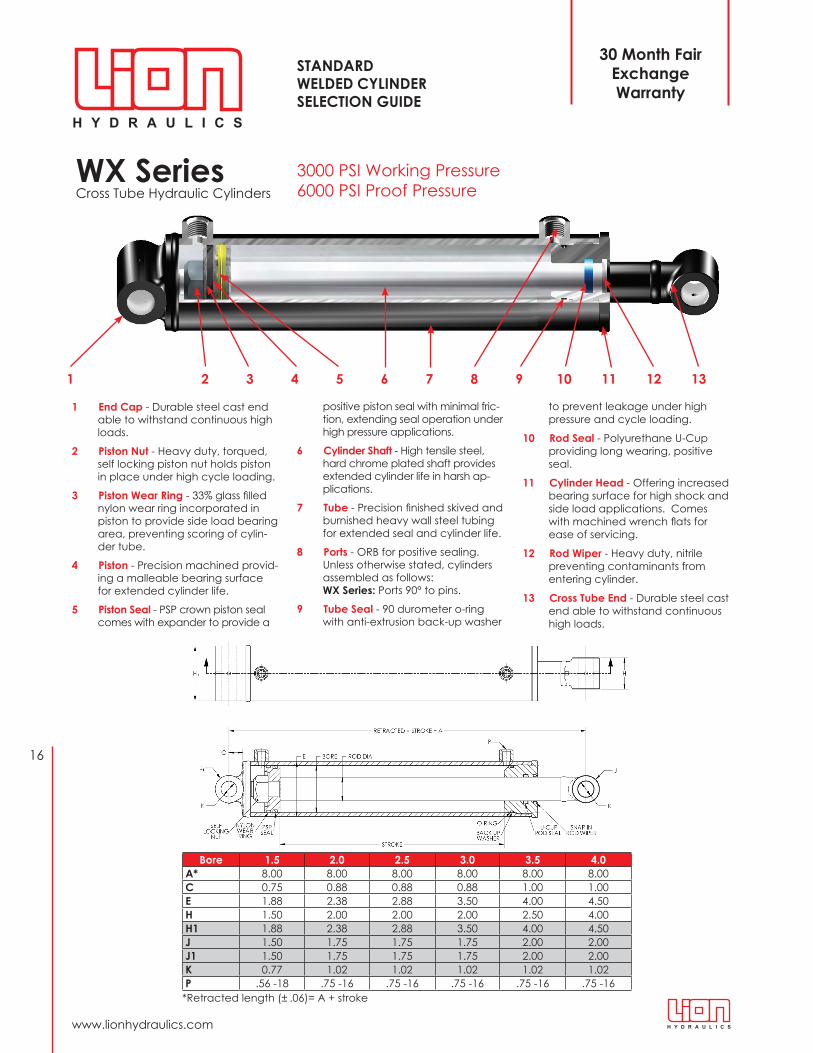
WX Series Cross Tube Hydraulic Cylinders
1 2 3 4 5 6 7 8 9 10 11 12 13
Bore 1.5 2.0 2.5 3.0 3.5 4.0A* 8 .00 8 .00 8 .00 8 .00 8 .00 8 .00C 0 .75 0 .88 0 .88 0 .88 1 .00 1 .00E 1 .88 2 .38 2 .88 3 .50 4 .00 4 .50H 1 .50 2 .00 2 .00 2 .00 2 .50 4 .00H1 1 .88 2 .38 2 .88 3 .50 4 .00 4 .50J 1 .50 1 .75 1 .75 1 .75 2 .00 2 .00J1 1 .50 1 .75 1 .75 1 .75 2 .00 2 .00K 0 .77 1 .02 1 .02 1 .02 1 .02 1 .02P .56 -18 .75 -16 .75 -16 .75 -16 .75 -16 .75 -16
*Retracted length (± .06)= A + stroke
1 End Cap - Durable steel cast end able to withstand continuous high loads .
2 Piston Nut - Heavy duty, torqued, self locking piston nut holds piston in place under high cycle loading .
3 Piston Wear Ring - 33% glass filled nylon wear ring incorporated in piston to provide side load bearing area, preventing scoring of cylin-der tube .
4 Piston - Precision machined provid-ing a malleable bearing surface for extended cylinder life.
5 Piston Seal - PSP crown piston seal comes with expander to provide a
positive piston seal with minimal fric-tion, extending seal operation under high pressure applications .
6 Cylinder Shaft - High tensile steel, hard chrome plated shaft provides extended cylinder life in harsh ap-plications .
7 Tube - Precision finished skived and burnished heavy wall steel tubing for extended seal and cylinder life.
8 Ports - ORB for positive sealing. Unless otherwise stated, cylinders assembled as follows: WX Series: Ports 90° to pins .
9 Tube Seal - 90 durometer o-ring with anti-extrusion back-up washer
to prevent leakage under high pressure and cycle loading .
10 Rod Seal - Polyurethane U-Cup providing long wearing, positive seal .
11 Cylinder Head - Offering increased bearing surface for high shock and side load applications . Comes with machined wrench flats for ease of servicing.
12 Rod Wiper - Heavy duty, nitrile preventing contaminants from entering cylinder .
13 Cross Tube End - Durable steel cast end able to withstand continuous high loads .
30 Month Fair Exchange Warranty

17
Toll-Free 1-800-665-0247 | Phone (204) 786-7921 | Fax (204)889-9120
WX Series Cross Tube Hydraulic Cylinders
WX
SERI
ES
Bore Stroke Rod Dia. Order No. Model
Pin to Pin Center Ship Wt lbs. Pin Dia
Max Rated PSI & Column Load on Full Extension
Retracted Extended PSI lbs.
1 .5"
8 .00 1 .00 644950 15WX08-100 16 24 9 3/4" 3000 530110 .00 1 .00 644951 15WX10-100 18 28 10 3/4" 3000 530112 .00 1 .00 644952 15WX12-100 20 32 11 3/4" 3000 530114 .00 1 .00 644953 15WX14-100 22 36 12 3/4" 3000 530116 .00 1 .00 644954 15WX16-100 24 40 13 3/4" 3000 530118 .00 1 .00 644955 15WX18-100 26 44 14 3/4" 3000 530120 .00 1 .00 644956 15WX20-100 28 48 15 3/4" 3000 530124 .00 1 .00 644957 15WX24-100 32 56 17 3/4" *2618 4626
2"
8 .00 1 .13 644900 20WX08-112 16 24 13 1" 3000 942510 .00 1 .13 644901 20WX10-112 18 28 14 1" 3000 942512 .00 1 .13 644902 20WX12-112 20 32 15 1" 3000 942514 .00 1 .13 644903 20WX14-112 22 36 17 1" 3000 942516 .00 1 .13 644904 20WX16-112 24 40 18 1" 3000 942518 .00 1 .13 644905 20WX18-112 26 44 19 1" 3000 942520 .00 1 .13 644906 20WX20-112 28 48 21 1" 3000 942524 .00 1 .13 644907 20WX24-112 32 56 23 1" *2359 7411
2 .5"
8 .00 1 .25 644910 25WX08-125 16 24 17 1" 3000 1472610 .00 1 .25 644911 25WX10-125 18 28 18 1" 3000 1472612 .00 1 .25 644912 25WX12-125 20 32 20 1" 3000 1472614 .00 1 .25 644913 25WX14-125 22 36 21 1" 3000 1472616 .00 1 .25 644914 25WX16-125 24 40 23 1" 3000 1472618 .00 1 .25 644915 25WX18-125 26 44 25 1" 3000 1472620 .00 1 .25 644916 25WX20-125 28 48 26 1" 3000 1472624 .00 1 .25 644917 25WX24-125 32 56 29 1" *2301 11295
3"
8 .00 1 .50 644920 30WX08-150 16 24 24 1" 3000 2120610 .00 1 .50 644921 30WX10-150 18 28 27 1" 3000 2120612 .00 1 .50 644922 30WX12-150 20 32 29 1" 3000 2120614 .00 1 .50 644923 30WX14-150 22 36 32 1" 3000 2120616 .00 1 .50 644924 30WX16-150 24 40 34 1" 3000 2120618 .00 1 .50 644925 30WX18-150 26 44 36 1" 3000 2120620 .00 1 .50 644926 30WX20-150 28 48 39 1" 3000 2120624 .00 1 .50 644927 30WX24-150 32 56 43 1" 3000 21206
3 .5"
8 .00 1 .75 644930 35WX08-175 16 24 32 1" 3000 2886310 .00 1 .75 644931 35WX10-175 18 28 35 1" 3000 2886312 .00 1 .75 644932 35WX12-175 20 32 38 1" 3000 2886314 .00 1 .75 644933 35WX14-175 22 36 41 1" 3000 2886316 .00 1 .75 644934 35WX16-175 24 40 44 1" 3000 2886318 .00 1 .75 644935 35WX18-175 26 44 47 1" 3000 2886320 .00 1 .75 644936 35WX20-175 28 48 50 1" 3000 2886324 .00 1 .75 644937 35WX24-175 32 56 57 1" 3000 28863
4"
8 .00 2 .00 644940 40WX08-200 16 24 39 1" 3000 3769910 .00 2 .00 644941 40WX10-200 18 28 43 1" 3000 3769912 .00 2 .00 644942 40WX12-200 20 32 47 1" 3000 3769914 .00 2 .00 644943 40WX14-200 22 36 50 1" 3000 3769916 .00 2 .00 644944 40WX16-200 24 40 54 1" 3000 3769918 .00 2 .00 644945 40WX18-200 26 44 58 1" 3000 3769920 .00 2 .00 644946 40WX20-200 28 48 61 1" 3000 3769924 .00 2 .00 644947 40WX24-200 32 56 69 1" 3000 37699
3 0 0 0 P S I
NOTE: * Indicates cylinder strength is affected, see page 6 for details.
18
www .lionhydraulics .com
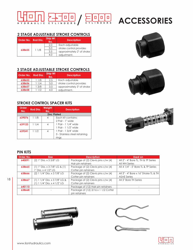
2 STAGE ADJUSTABLE STROKE CONTROLS
STROKE CONTROL SPACER KITS
PIN KITS
3 STAGE ADJUSTABLE STROKE CONTROLS
ACCESSORIES
Order No. Rod DIa. Ship Wt lbs. Description
638655 1 1/8
2 .0 Each adjustable stroke control provides approximately 2" of stroke adjustment.
3 .03 .54 .0
Order No. Rod DIa. Ship Wt lbs. Description
638653 1 1/8 2 .5 Each adjustable stroke control provides approximately 3" of stroke adjustment.
638656 1 1/4 3 .0638657 1 3/8 3 .5638658 1 1/2 4 .0
Order No. Rod DIa. Weight
lbs. Description
Zinc Plated639076 1 1/8 4 Each kit contains:
2 Pair - 1" wide1 Pair - 1 1/4" wide1 Pair - 1 1/2" wide1 Pair - 1 3/4" wide5 - Stainless steel retaining rings
639123 1 1/4 4
639241 1 1/2 4
Order No. Size Description Used on640091 (2) 1" Dia . x 3 3/8" LG Package of (2) Clevis pins c/w (4)
Hair pin retainersAll 2" - 4" Bore TL, TH & TP SeriesAll WH Series
638665 (1) 1" Dia. x 3 7/8" LG & (1) 1" Dia . x 4 1/2" LG
Package of (2) Clevis pins c/w (4) Cotter pin retainers
All 4 1/4" - 5" Bore TL & TP Series
638666 (2) 1 1/4" Dia . x 3 7/8" LG Package of (2) Clevis pins c/w (4) Cotter pin retainers
All 3" - 4" Bore x 16" Stroke TL & TH ASAE Series
638667 (1) 1 1/4" Dia. x 3 7/8" LG & (1) 1 1/4" Dia . x 4 1/2" LG
Package of (2) Clevis pins c/w (4) Cotter pin retainers
All 5" Bore TH Series
640110 - Package of (12) Hair pin retainers -638668 - Package of (12) 3/16 x 1 1/2 Cotter
pin retainers -
/

19
Toll-Free 1-800-665-0247 | Phone (204) 786-7921 | Fax (204)889-9120
2500 PSI (TL SERIES)
BREATHERS FOR SINGLE ACTING APPLICATIONS PORT ADAPTER
NOTE: TL series cylinder repair kits can be used in previous TR series cylinders with corresponding bore and shaft diameters.
CYLINDER REPAIR KITS3000 PSI (TH & TP SERIES)
Order No. Description640368 3/8 NPT640370 1/2 NPT648277 9/16 ORB648278 3/4 ORB
Order No. Description624643 3/4 - 16 ORB - 1/2 NPT
Bore Rod Dia.
Order No. Model No. Description
2 .0" 1 .125 639572 RK20L - 112 Up to 30" stroke
2 .5" 1 .125 639573 RK25L - 112 Up to 16" stroke1 .25 639574 RK25L - 125 18" stroke and up
3 .0" 1 .25 639575 RK30L - 125 Up to 20" stroke1 .50 639576 RK30L - 150 24" stroke and up
3 .5" 1 .25 639577 RK35L - 125 Up to 16" stroke1 .50 639578 RK35L - 150 18" stroke and up
4 .0"
1 .25 639579 RK40L - 125 Up to 16" stroke1 .50 639580 RK40L - 150 18" to 24" stroke1 .75 639581 RK40L - 175 24" stroke2 .00 639582 RK40L - 200 30" stroke and up
5 .0" 1 .50 639583 RK50L - 150 Up to 10" stroke2 .00 639584 RK50L - 200 12" to 36" stroke
Bore Rod Dia.
Order No. Model No. Description
2 .0" 1 .125 639542 RK20H - 112 Up to 24" stroke
2 .5" 1 .125 639555 RK25H - 112 Up to 14" stroke & Rephasing1 .25 639556 RK25H - 125 16" to 24" stroke
2 .7" 1 .125 639557 RK27H - 112 Rephasing cylinder repair kit
3 .0" 1 .25 639558 RK30H - 125 Up to 14" stroke & Rephasing1 .50 639559 RK30H - 150 16" to 24" stroke
3 .2" 1 .25 639560 RK32H - 125 Rephasing cylinder repair kit
3 .5" 1 .25 639561 RK35H - 125 Up to 14" stroke & Rephasing1 .50 639562 RK35H - 150 16" to 24" stroke
3 .7" 1 .375 639563 RK37H - 137 Rephasing cylinder repair kit
4 .0"
1 .375 639564 RK40H - 137 Up to 14" stroke & Rephasing1 .50 639565 RK40H - 150 Rephasing cylinder repair kit1 .75 639566 RK40H - 175 16" to 24" stroke2 .00 639585 RK40H - 200 30" stroke and up
4 .2" 1 .50 639567 RK42H - 150 Rephasing cylinder repair kit4 .5" 1 .50 639568 RK45H - 150 Rephasing cylinder repair kit4 .7" 1 .50 639569 RK47H - 150 Rephasing cylinder repair kit
5 .0" 1 .50 639570 RK50H - 150 Rephasing cylinder repair kit2 .00 639571 RK50H - 200 8" to 24" stroke
ACCESSORIES/
/
Bore Rod Dia.
Order No. Model No. Description
1 .5" 1 .00 644457 RK15WD - 100 Up to 24" stroke WX2 .0" 1 .13 644338 RK20WD - 112 Up to 24" stroke WH & WX
2 .5" 1 .13 644340 RK25WD - 112 Up to 14" stroke WH1 .25 644341 RK25WD - 125 16" to 24" stroke WH & all WX
3 .0" 1 .25 644343 RK30WD - 125 Up to 14" stroke WH1 .50 644345 RK30WD - 150 16" to 24" stroke WH & all WX
3 .5"1 .25 644421 RK35WD - 125 Up to 14" stroke WH1 .50 639346 RK35WD - 150 16" to 24" stroke WH & WX1 .75 639061 RK35WD - 175 Up to 24" stroke WX
4 .0"1 .38 639746 RK40WD - 138 Up to 14" stroke WH1 .75 639349 RK40WD - 175 16" to 24" stroke WH2 .00 639327 RK40WD - 200 Up to 24" Stroke WX
3000 PSI (WH & WX SERIES)

Hydraulic Cylinder Display
Distributed by:
Quality and Service Since 1935.
PRINTED IN CANADA 231827R12 0107
For placing orders or for further product information contact your local Lion Hydraulics sales representative, or contact:
U.S.A. CORPORATE OFFICE : LION HYDRAULICSP .O . Box 20476Minneapolis, Minnesota55431Telephone 204-786-7921Toll Free 1-800-665-0247Fax [email protected] Orders Only: Fax [email protected]
U.S.A WAREHOUSES:
Austell, GeorgiaDallas, Texas Fresno, California
CANADIAN CORPORATE OFFICE:
LION HYDRAULICS51 Burmac Road, P .O . Box 429 Winnipeg, Manitoba, CanadaR3C 3E4Telephone 204-786-7921Toll Free 1-800-665-0247Fax 204-889-9120 [email protected] Orders Only: Fax [email protected]
CANADIAN WAREHOUSES:
Winnipeg, ManitobaMontreal, Quebec
www.lionhydraulics.com