TicTacToe Doc
9
172 EE108 Class Notes first round. Each match in the tournament is performed using a magnitude comparator (Section 8.5). To break ties in favor of the lower number input, the magnitude comparator computes a signal c1gt0 that is true if in1 ¿ in0. If they are tied, this signal is false, indicating that in0 has won the match. A similar comparison is made between in3 and in2. To select the competitors for the second round, two 2:1 multiplexers (Sec- tion 8.2) are used. Each multiplexer selects the winner of a first round match using the comparator output as the select signal. A third magnitude comparator performs the second round match - compar- ing the two winners output by the multiplexers. The output of this second round comparator is the MSB of the priority arbiter. If this signal is true, the winner is in2 or in3; if its false, the winner is in0 or in1. To get the LSB of the priority arbiter output, we select the output of the winning first round comparator. This is accomplished with a single-bit-wide 2:1 multiplexer controlled by the output of the final comparator. 9.4 Tic-Tac-Toe In this section we develop a combinational circuit that plays the game of tic-tac- toe. Given a starting board position, it selects the square on which to play its next move. Being a combinational circuit, it can only play one move. However, it can easily be transformed into a sequential circuit (Chapter 14) that plays an entire game. Our first task is to decide how to represent the playing board. We represent the input board position as two nine-bit vectors: one xin encodes the position of the X’s and the other oin encodes the position of the O’s. We map each nine- bit vector to the board as shown in Figure 9.10(a). The upper left corner is the LSB and the bottom right corner is the MSB. For example, the board shown in Figure 9.10(b) is represented by xin = 100000001 and oin = 00011000. For a legal board position, xin and oin must be orthogonal. That is xin ∧ oin = 0. Strictly speaking, a legal board should also have N O ≥ N X ≥ N O − 1, where N O is the number of bits set in oin and N X is the number of bits set in xin. If X goes first, the input should always have equal numbers of bits set in the two inputs. If O goes first, the input will always have one more bit set in oin than in xin. Our output will also be a nine-bit vector xout that indicates which position our circuit will be playing. A legal move must be orthogonal to both input vectors. On the next turn xin will be replaced by the OR of the old xin and xout and the opponent will have added a bit to oin. Now that we have represented the board, our next step is to structure our circuit. A useful structure is as a set of ordered strategy modules that each apply a strategy to generate the next move. The highest priority module that is able to generate a move is selected. For example, a good set of strategy modules is:
-
Upload
syed-ali-raza -
Category
Documents
-
view
228 -
download
2
Transcript of TicTacToe Doc
172 EE108 Class Notes
first round.Each match in the tournament is performed using a magnitude comparator
(Section 8.5). To break ties in favor of the lower number input, the magnitudecomparator computes a signal c1gt0 that is true if in1 ¿ in0. If they are tied,this signal is false, indicating that in0 has won the match. A similar comparisonis made between in3 and in2.
To select the competitors for the second round, two 2:1 multiplexers (Sec-tion 8.2) are used. Each multiplexer selects the winner of a first round matchusing the comparator output as the select signal.
A third magnitude comparator performs the second round match - compar-ing the two winners output by the multiplexers. The output of this secondround comparator is the MSB of the priority arbiter. If this signal is true, thewinner is in2 or in3; if its false, the winner is in0 or in1.
To get the LSB of the priority arbiter output, we select the output of thewinning first round comparator. This is accomplished with a single-bit-wide 2:1multiplexer controlled by the output of the final comparator.
9.4 Tic-Tac-Toe
In this section we develop a combinational circuit that plays the game of tic-tac-toe. Given a starting board position, it selects the square on which to play itsnext move. Being a combinational circuit, it can only play one move. However,it can easily be transformed into a sequential circuit (Chapter 14) that plays anentire game.
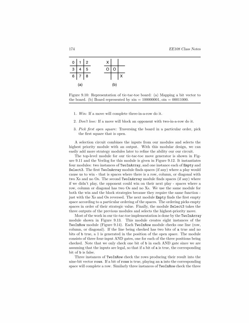
Our first task is to decide how to represent the playing board. We representthe input board position as two nine-bit vectors: one xin encodes the positionof the X’s and the other oin encodes the position of the O’s. We map each nine-bit vector to the board as shown in Figure 9.10(a). The upper left corner is theLSB and the bottom right corner is the MSB. For example, the board shown inFigure 9.10(b) is represented by xin = 100000001 and oin = 00011000. For alegal board position, xin and oin must be orthogonal. That is xin ∧ oin = 0.
Strictly speaking, a legal board should also have NO ≥ NX ≥ NO −1, whereNO is the number of bits set in oin and NX is the number of bits set in xin. IfX goes first, the input should always have equal numbers of bits set in the twoinputs. If O goes first, the input will always have one more bit set in oin thanin xin.
Our output will also be a nine-bit vector xout that indicates which positionour circuit will be playing. A legal move must be orthogonal to both inputvectors. On the next turn xin will be replaced by the OR of the old xin andxout and the opponent will have added a bit to oin.
Now that we have represented the board, our next step is to structure ourcircuit. A useful structure is as a set of ordered strategy modules that eachapply a strategy to generate the next move. The highest priority module that isable to generate a move is selected. For example, a good set of strategy modulesis:

Copyright (c) 2002-2006 by W.J Dally, all rights reserved 173
//-----------------------------------------------------------------------------// 4-input Priority Arbiter// Outputs the index of the input with the highest value// Inputs:// in0, in1, in2, in3 - n-bit binary input values// Out:// out - 2-bit index of the input with the highest value//// We pick the "winning" output via a tournament.// In the first round we compare in0 against in1 and in2 against in3// The second round compares the winners of the first round.// The MSB comes from the final round, the LSB from the selected first round.//// Ties are given to the lower numbered input.//-----------------------------------------------------------------------------module PriorityArbiter(in0, in1, in2, in3, out) ;parameter n = 8 ; // width of inputsinput [n-1:0] in0, in1, in2, in3 ;output [1:0] out ;wire [n-1:0] match0winner, match1winner ;wire [1:0] out ;
// first round of tournamentMagComp #(n) round0match0(in1, in0, c1gt0) ; // compare in0 and in1MagComp #(n) round0match1(in3, in2, c3gt2) ; // compare in2 and in3
// select first round winnersMux2 #(n) match0(in0, in1, {c1gt0, ~c1gt0}, match0winner) ;Mux2 #(n) match1(in2, in3, {c3gt2, ~c3gt2}, match1winner) ;
// compare round0 winnersMagComp #(n) round1(match1winner, match0winner, out[1]) ;
// select winning LSB indexMux2 #(1) winningLSB(c1gt0, c3gt2, {out[1], ~out[1]}, out[0]) ;
endmodule//-----------------------------------------------------------------------------
Figure 9.9: Verilog description of a four-input priority arbiter.
174 EE108 Class Notes
0 1 2
3 4 5
6 7 8
X
O
X
O
(a) (b)
Figure 9.10: Representation of tic-tac-toe board: (a) Mapping a bit vector tothe board. (b) Board represented by xin = 100000001, oin = 00011000.
1. Win: If a move will complete three-in-a-row do it.
2. Don’t lose: If a move will block an opponent with two-in-a-row do it.
3. Pick first open square: Traversing the board in a particular order, pickthe first square that is open.
A selection circuit combines the inputs from our modules and selects thehighest priority module with an output. With this modular design, we caneasily add more strategy modules later to refine the ability our our circuit.
The top-level module for our tic-tac-toe move generator is shown in Fig-ure 9.11 and the Verilog for this module is given in Figure 9.12. It instantiatesfour modules: two instances of TwoInArray, and one instance each of Empty andSelect3. The first TwoInArray module finds spaces (if any) where a play wouldcause us to win - that is spaces where there is a row, column, or diagonal withtwo Xs and no Os. The second TwoInArray module finds spaces (if any) whereif we didn’t play, the opponent could win on their next play - spaces where arow, column or diagonal has two Os and no Xs. We use the same module forboth the win and the block strategies because they require the same function -just with the Xs and Os reversed. The next module Empty finds the first emptyspace according to a particular ordering of the spaces. The ordering picks emptyspaces in order of their strategic value. Finally, the module Select3 takes thethree outputs of the previous modules and selects the highest-priority move.
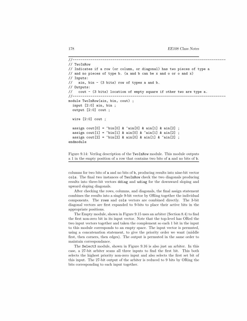
Most of the work in our tic-tac-toe implementation is done by the TwoInArraymodule shown in Figure 9.13. This module creates eight instances of theTwoInRow module (Figure 9.14). Each TwoInRow module checks one line (row,column, or diagonal). If the line being checked has two bits of a true and nobits of b true, a 1 is generated in the position of the open space. The moduleconsists of three four-input AND gates, one for each of the three positions beingchecked. Note that we only check one bit of b in each AND gate since we areassuming that the inputs are legal, so that if a bit of a is true, the correspondingbit of b is false.
Three instances of TwoInRow check the rows producing their result into thenine-bit vector rows. If a bit of rows is true, playing an a into the correspondingspace will complete a row. Similarly three instances of TwoInRow check the three

Copyright (c) 2002-2006 by W.J Dally, all rights reserved 175
Tw
oInA
rrayain
bin
cout
Tw
oInA
rrayain
bin
cout
xin
9
oin9
Sel
ect3
Em
pty
9
9
9
win
block
empty
xout9
win
don't lose
first open square
a
b
c
out
Figure 9.11: High-level design of the tic-tac-toe module. Three strategy modulesaccept the inputs, xin and oin, and compute possible moves to win, not lose,or pick an empty square. The Select3 module then picks the highest priorityof these possible moves to be the next move.

176 EE108 Class Notes
//-----------------------------------------------------------------------------// TicTacToe// Generates a move for X in the game of tic-tac-toe// Inputs:// xin, oin - (9-bit) current positions of X and O.// Out:// xout - (9-bit) one hot position of next X.//// Inputs and outputs use a board mapping of://// 0 | 1 | 2// ---+---+---// 3 | 4 | 5// ---+---+---// 6 | 7 | 8//// The top-level circuit instantiates strategy modules that each generate// a move according to their strategy and a selector module that selects// the highest-priority strategy module with a move.//// The win strategy module picks a space that will win the game if any exists.//// The block strategy module picks a space that will block the opponent// from winning.//// The empty strategy module picks the first open space - using a particular// ordering of the board.//-----------------------------------------------------------------------------module TicTacToe(xin, oin, xout) ;input [8:0] xin, oin ;output [8:0] xout ;wire [8:0] win, block, empty ;
TwoInArray winx(xin, oin, win) ; // win if we canTwoInArray blockx(oin, xin, block) ; // try to block o from winningEmpty emptyx(~(oin | xin), empty) ; // otherwise pick empty spaceSelect3 comb(win, block, empty, xout) ; // pick highest priority
endmodule
Figure 9.12: Top-level Verilog description for our tic-tac-toe move generator.
Copyright (c) 2002-2006 by W.J Dally, all rights reserved 177
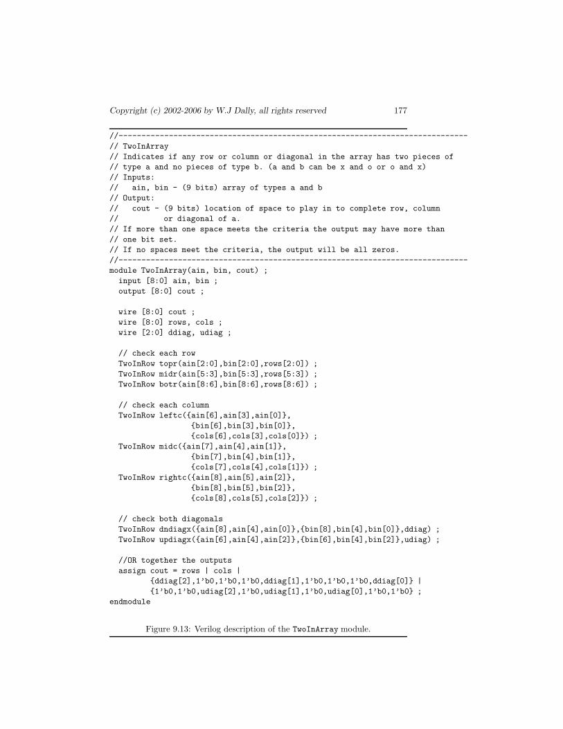
//-----------------------------------------------------------------------------// TwoInArray// Indicates if any row or column or diagonal in the array has two pieces of// type a and no pieces of type b. (a and b can be x and o or o and x)// Inputs:// ain, bin - (9 bits) array of types a and b// Output:// cout - (9 bits) location of space to play in to complete row, column// or diagonal of a.// If more than one space meets the criteria the output may have more than// one bit set.// If no spaces meet the criteria, the output will be all zeros.//-----------------------------------------------------------------------------module TwoInArray(ain, bin, cout) ;input [8:0] ain, bin ;output [8:0] cout ;
wire [8:0] cout ;wire [8:0] rows, cols ;wire [2:0] ddiag, udiag ;
// check each rowTwoInRow topr(ain[2:0],bin[2:0],rows[2:0]) ;TwoInRow midr(ain[5:3],bin[5:3],rows[5:3]) ;TwoInRow botr(ain[8:6],bin[8:6],rows[8:6]) ;
// check each columnTwoInRow leftc({ain[6],ain[3],ain[0]},
{bin[6],bin[3],bin[0]},{cols[6],cols[3],cols[0]}) ;
TwoInRow midc({ain[7],ain[4],ain[1]},{bin[7],bin[4],bin[1]},{cols[7],cols[4],cols[1]}) ;
TwoInRow rightc({ain[8],ain[5],ain[2]},{bin[8],bin[5],bin[2]},{cols[8],cols[5],cols[2]}) ;
// check both diagonalsTwoInRow dndiagx({ain[8],ain[4],ain[0]},{bin[8],bin[4],bin[0]},ddiag) ;TwoInRow updiagx({ain[6],ain[4],ain[2]},{bin[6],bin[4],bin[2]},udiag) ;
//OR together the outputsassign cout = rows | cols |
{ddiag[2],1’b0,1’b0,1’b0,ddiag[1],1’b0,1’b0,1’b0,ddiag[0]} |{1’b0,1’b0,udiag[2],1’b0,udiag[1],1’b0,udiag[0],1’b0,1’b0} ;
endmodule
Figure 9.13: Verilog description of the TwoInArray module.
178 EE108 Class Notes
//-----------------------------------------------------------------------------// TwoInRow// Indicates if a row (or column, or diagonal) has two pieces of type a// and no pieces of type b. (a and b can be x and o or o and x)// Inputs:// ain, bin - (3 bits) row of types a and b.// Outputs:// cout - (3 bits) location of empty square if other two are type a.//-----------------------------------------------------------------------------module TwoInRow(ain, bin, cout) ;input [2:0] ain, bin ;output [2:0] cout ;
wire [2:0] cout ;
assign cout[0] = ~bin[0] & ~ain[0] & ain[1] & ain[2] ;assign cout[1] = ~bin[1] & ain[0] & ~ain[1] & ain[2] ;assign cout[2] = ~bin[2] & ain[0] & ain[1] & ~ain[2] ;
endmodule
Figure 9.14: Verilog description of the TwoInRow module. This module outputsa 1 in the empty position of a row that contains two bits of a and no bits of b.
columns for two bits of a and no bits of b, producing results into nine-bit vectorcols. The final two instances of TwoInRow check the two diagonals producingresults into three-bit vectors ddiag and udiag for the downward sloping andupward sloping diagonals.
After checking the rows, columns, and diagonals, the final assign statementcombines the results into a single 9-bit vector by ORing together the individualcomponents. The rows and cols vectors are combined directly. The 3-bitdiagonal vectors are first expanded to 9-bits to place their active bits in theappropriate positions.
The Empty module, shown in Figure 9.15 uses an arbiter (Section 8.4) to findthe first non-zero bit in its input vector. Note that the top-level has ORed thetwo input vectors together and taken the complement so each 1 bit in the inputto this module corresponds to an empty space. The input vector is permuted,using a concatenation statement, to give the priority order we want (middlefirst, then corners, then edges). The output is permuted in the same order tomaintain correspondance.
The Select3 module, shown in Figure 9.16 is also just an arbiter. In thiscase, a 27-bit arbiter scans all three inputs to find the first bit. This bothselects the highest priority non-zero input and also selects the first set bit ofthis input. The 27-bit output of the arbiter is reduced to 9 bits by ORing thebits corresponding to each input together.

Copyright (c) 2002-2006 by W.J Dally, all rights reserved 179
//-----------------------------------------------------------------------------// Empty// Pick first space not in input. Permute vector so middle comes first,// then corners, then edges.// Inputs:// in - (9 bits) occupied spaces// Outputs:// out - (9 bits) first empty space//-----------------------------------------------------------------------------module Empty(in, out) ;input [8:0] in ;output [8:0] out ;
RArb #(9) ra({in[4],in[0],in[2],in[6],in[8],in[1],in[3],in[5],in[7]},{out[4],out[0],out[2],out[6],out[8],out[1],out[3],out[5],out[7]}) ;
endmodule
Figure 9.15: Verilog description of a Empty module. This module uses an arbiterto find the first empty space searching first the middle space, then the fourcorners, then the four edges.
//-----------------------------------------------------------------------------// Select3// Picks the highest priority bit from 3 9-bit vectors// Inputs:// a, b, c - (9 bits) Input vectors// Outputs:// out - (9 bits) One hot output has a bit set (if any) in the highest// position of the highest priority input.//-----------------------------------------------------------------------------module Select3(a, b, c, out) ;input [8:0] a, b, c;output [8:0] out ;wire [26:0] x ;
RArb #(27) ra({a,b,c},x) ;
wire [8:0] out = x[26:18] | x[17:9] | x[8:0] ;endmodule
Figure 9.16: Verilog description of the Select3 module. A 27-input arbiter isused to find the first set bit of the highest priority strategy module. A three-wayOR combines the arbiter outputs.

180 EE108 Class Notes
It is worth pointing out that the entire tic-tac-toe module is at the bot-tom level built entire from just two module types: TwoInRow, and RArb. Thisdemonstrates the utility of combinational building blocks.
A simple test bench for the tic-tac-toe module is shown in Figure 9.17. Thetest bench instantiates two copies of the TicTacToe module. One plays X andthe other plays O. The test bench starts by checking the module that plays X,called dut in the test bench, with some directed testing. The five vectors checkempty, win, and block strategies and check row, column, and diagonal patterns.
After the five directed patterns, the test bench plays a game of TicTacToeby ORing the outputs of each module into its input to compute the input for thenext round. The results of the game (obtained by writing a script to massagethe output of the $display statements) is shown in Figure 9.18.
The game starts with an empty board. The empty rule applies and X playsto the center - our highest priority empty space. The empty rule applies for thenext two turns as well and O and X take the top two corners. At this point Xhas two in a row, so the block rule applies and O plays to the bottom left corner(position 6) completing the first row of the figure.
The second row of the figure starts with the block rule causing X to play onthe left edge (position 3). O then blocks X in the middle row. At this pointempty cause X to take the remaining corner. In the last two moves empty causesO and X to fill the two remaining open spaces. The game ends in a draw.
The verification performed by this test bench is by no means adequate to ver-ify proper module operation. Many combinations of inputs have not been tried.To thoroughly verify the module a checker is required. This would typically beimplemented in a high-level programming language (like “C”) and interfacedto the simulator. Proper operation would then be verified by comparing thesimulation results to the high-level language model. One hopes that the samemistake would not be made in both models.
Once a checker is in place, we still need to pick the test vectors. After abit more directed testing (e.g., win, block, near-win, and near-block on all eightlines) we could take two approaches. We could exhaustively test the module.There are 218 input cases. Depending on how fast our simulator runs we mayhave time to try them all. Alternatively, if we don’t have time for exhaustivetesting, we could apply random testing, randomly generating input patterns andchecking the resulting outputs.
9.5 Exercises
9–1 Multiple of 5 circuit. Using an approach similar to the multiple-of-3 circuitof Section 9.1, design a multiple-of-5 circuit that outputs true iff its 8-bit input is a multiple of 5. (Optional, code your design in Verilog andexhaustively verify it with a test bench.)
9–2 Calendar circuit. Recode the NextDayOfWeek module so it will work witharbitrary definitions of the constants ‘SUNDAY, ‘MONDAY, ..., ‘SATURDAY.