TIBCO LogLogic?? Log Management Intelligence (LMI) · PDF file · 2017-09-26BUT NOT...
425
TIBCO LogLogic ® Log Management Intelligence (LMI) Administration Guide Software Release 6.1.1 July 2017 Two-Second Advantage ®
Transcript of TIBCO LogLogic?? Log Management Intelligence (LMI) · PDF file · 2017-09-26BUT NOT...

Two-Second Adv
TIBCO LogLogic® Log Management Intelligence (LMI)
Administration GuideSoftware Release 6.1.1July 2017
antage®

Important Information
SOME TIBCO SOFTWARE EMBEDS OR BUNDLES OTHER TIBCO SOFTWARE. USE OF SUCH EMBEDDED OR BUNDLED TIBCO SOFTWARE IS SOLELY TO ENABLE THE FUNCTIONALITY (OR PROVIDE LIMITED ADD-ON FUNCTIONALITY) OF THE LICENSED TIBCO SOFTWARE. THE EMBEDDED OR BUNDLED SOFTWARE IS NOT LICENSED TO BE USED OR ACCESSED BY ANY OTHER TIBCO SOFTWARE OR FOR ANY OTHER PURPOSE.USE OF TIBCO SOFTWARE AND THIS DOCUMENT IS SUBJECT TO THE TERMS AND CONDITIONS OF A LICENSE AGREEMENT FOUND IN EITHER A SEPARATELY EXECUTED SOFTWARE LICENSE AGREEMENT, OR, IF THERE IS NO SUCH SEPARATE AGREEMENT, THE CLICKWRAP END USER LICENSE AGREEMENT WHICH IS DISPLAYED DURING DOWNLOAD OR INSTALLATION OF THE SOFTWARE (AND WHICH IS DUPLICATED IN THE LICENSE FILE) OR IF THERE IS NO SUCH SOFTWARE LICENSE AGREEMENT OR CLICKWRAP END USER LICENSE AGREEMENT, THE LICENSE(S) LOCATED IN THE “LICENSE” FILE(S) OF THE SOFTWARE. USE OF THIS DOCUMENT IS SUBJECT TO THOSE TERMS AND CONDITIONS, AND YOUR USE HEREOF SHALL CONSTITUTE ACCEPTANCE OF AND AN AGREEMENT TO BE BOUND BY THE SAME.This document contains confidential information that is subject to U.S. and international copyright laws and treaties. No part of this document may be reproduced in any form without the written authorization of TIBCO Software Inc.TIBCO, Two-Second Advantage, and LogLogic are either registered trademarks or trademarks of TIBCO Software Inc. in the United States and/or other countries.All other product and company names and marks mentioned in this document are the property of their respective owners and are mentioned for identification purposes only.THIS SOFTWARE MAY BE AVAILABLE ON MULTIPLE OPERATING SYSTEMS. HOWEVER, NOT ALL OPERATING SYSTEM PLATFORMS FOR A SPECIFIC SOFTWARE VERSION ARE RELEASED AT THE SAME TIME. SEE THE README FILE FOR THE AVAILABILITY OF THIS SOFTWARE VERSION ON A SPECIFIC OPERATING SYSTEM PLATFORM.THIS DOCUMENT IS PROVIDED “AS IS” WITHOUT WARRANTY OF ANY KIND, EITHER EXPRESS OR IMPLIED, INCLUDING, BUT NOT LIMITED TO, THE IMPLIED WARRANTIES OF MERCHANTABILITY, FITNESS FOR A PARTICULAR PURPOSE, OR NON-INFRINGEMENT.THIS DOCUMENT COULD INCLUDE TECHNICAL INACCURACIES OR TYPOGRAPHICAL ERRORS. CHANGES ARE PERIODICALLY ADDED TO THE INFORMATION HEREIN; THESE CHANGES WILL BE INCORPORATED IN NEW EDITIONS OF THIS DOCUMENT. TIBCO SOFTWARE INC. MAY MAKE IMPROVEMENTS AND/OR CHANGES IN THE PRODUCT(S) AND/OR THE PROGRAM(S) DESCRIBED IN THIS DOCUMENT AT ANY TIME.THE CONTENTS OF THIS DOCUMENT MAY BE MODIFIED AND/OR QUALIFIED, DIRECTLY OR INDIRECTLY, BY OTHER DOCUMENTATION WHICH ACCOMPANIES THIS SOFTWARE, INCLUDING BUT NOT LIMITED TO ANY RELEASE NOTES AND "READ ME" FILES.Copyright © 2002-2017 TIBCO Software Inc. All rights reserved.
TIBCO Software Inc. Confidential Information

| iii
Contents
Preface . . . . . . . . . . . . . . . . . . . . . . . . . . . . . . . . . . . . . . . . . . . . . . . . . . . . . . . . . . . . . . . . . . . . . . . xiii
Related Documents . . . . . . . . . . . . . . . . . . . . . . . . . . . . . . . . . . . . . . . . . . . . . . . . . . . . . . . . . . . . . . . . . . . . . . . .xiv
Typographical Conventions . . . . . . . . . . . . . . . . . . . . . . . . . . . . . . . . . . . . . . . . . . . . . . . . . . . . . . . . . . . . . . . . . .xvi
Connecting with TIBCO Resources . . . . . . . . . . . . . . . . . . . . . . . . . . . . . . . . . . . . . . . . . . . . . . . . . . . . . . . . . . . xviiiHow to Join TIBCO Community . . . . . . . . . . . . . . . . . . . . . . . . . . . . . . . . . . . . . . . . . . . . . . . . . . . . . . . . . . xviiiHow to Access TIBCO Documentation. . . . . . . . . . . . . . . . . . . . . . . . . . . . . . . . . . . . . . . . . . . . . . . . . . . . . xviiiHow to Contact TIBCO Support . . . . . . . . . . . . . . . . . . . . . . . . . . . . . . . . . . . . . . . . . . . . . . . . . . . . . . . . . . xviii
Chapter 1 TIBCO LogLogic® Appliances Overview . . . . . . . . . . . . . . . . . . . . . . . . . . . . . . . . . . . .1
LogLogic Appliance Overview . . . . . . . . . . . . . . . . . . . . . . . . . . . . . . . . . . . . . . . . . . . . . . . . . . . . . . . . . . . . . . . . . 2
Appliance Administrator Functions . . . . . . . . . . . . . . . . . . . . . . . . . . . . . . . . . . . . . . . . . . . . . . . . . . . . . . . . . . . . . 3
LogLogic Product Families. . . . . . . . . . . . . . . . . . . . . . . . . . . . . . . . . . . . . . . . . . . . . . . . . . . . . . . . . . . . . . . . . . . . 5LogLogic LX Product Family. . . . . . . . . . . . . . . . . . . . . . . . . . . . . . . . . . . . . . . . . . . . . . . . . . . . . . . . . . . . . . . 5LogLogic MX Product Family . . . . . . . . . . . . . . . . . . . . . . . . . . . . . . . . . . . . . . . . . . . . . . . . . . . . . . . . . . . . . . 6LogLogic ST Product Family. . . . . . . . . . . . . . . . . . . . . . . . . . . . . . . . . . . . . . . . . . . . . . . . . . . . . . . . . . . . . . . 6LogLogic EVA . . . . . . . . . . . . . . . . . . . . . . . . . . . . . . . . . . . . . . . . . . . . . . . . . . . . . . . . . . . . . . . . . . . . . . . . . . 7Scalable Infrastructure . . . . . . . . . . . . . . . . . . . . . . . . . . . . . . . . . . . . . . . . . . . . . . . . . . . . . . . . . . . . . . . . . . . 8
Chapter 2 Managing Appliances with Management Station . . . . . . . . . . . . . . . . . . . . . . . . . . . . .9
Introduction to Management Station . . . . . . . . . . . . . . . . . . . . . . . . . . . . . . . . . . . . . . . . . . . . . . . . . . . . . . . . . . . 10Management Station Clusters . . . . . . . . . . . . . . . . . . . . . . . . . . . . . . . . . . . . . . . . . . . . . . . . . . . . . . . . . . . . 10
Creating a Management Station Cluster . . . . . . . . . . . . . . . . . . . . . . . . . . . . . . . . . . . . . . . . . . . . . . . . . . . . . . . . 12
Adding Appliances to a Management Station Cluster . . . . . . . . . . . . . . . . . . . . . . . . . . . . . . . . . . . . . . . . . . . . . . 14
Managing Appliances from a Management Station . . . . . . . . . . . . . . . . . . . . . . . . . . . . . . . . . . . . . . . . . . . . . . . . 15Designating the Current Management Station Appliance. . . . . . . . . . . . . . . . . . . . . . . . . . . . . . . . . . . . . . . . 16Monitoring the Status of Managed Appliances . . . . . . . . . . . . . . . . . . . . . . . . . . . . . . . . . . . . . . . . . . . . . . . . 16Management Station and Regular Appliance Features . . . . . . . . . . . . . . . . . . . . . . . . . . . . . . . . . . . . . . . . . 18
Chapter 3 Managing Log Sources . . . . . . . . . . . . . . . . . . . . . . . . . . . . . . . . . . . . . . . . . . . . . . . . .21
Managing Devices . . . . . . . . . . . . . . . . . . . . . . . . . . . . . . . . . . . . . . . . . . . . . . . . . . . . . . . . . . . . . . . . . . . . . . . . . 22View Devices . . . . . . . . . . . . . . . . . . . . . . . . . . . . . . . . . . . . . . . . . . . . . . . . . . . . . . . . . . . . . . . . . . . . . . . . . 23Adding or Modifying Devices . . . . . . . . . . . . . . . . . . . . . . . . . . . . . . . . . . . . . . . . . . . . . . . . . . . . . . . . . . . . . 27Copying a Device . . . . . . . . . . . . . . . . . . . . . . . . . . . . . . . . . . . . . . . . . . . . . . . . . . . . . . . . . . . . . . . . . . . . . . 29Updating a Device’s Type . . . . . . . . . . . . . . . . . . . . . . . . . . . . . . . . . . . . . . . . . . . . . . . . . . . . . . . . . . . . . . . . 29Updating Device Name Resolution. . . . . . . . . . . . . . . . . . . . . . . . . . . . . . . . . . . . . . . . . . . . . . . . . . . . . . . . . 30
TIBCO LogLogic® Log Management Intelligence (LMI) Administration Guide

iv | Contents
Removing Devices . . . . . . . . . . . . . . . . . . . . . . . . . . . . . . . . . . . . . . . . . . . . . . . . . . . . . . . . . . . . . . . . . . . . . 30
Managing File Transfer Rules . . . . . . . . . . . . . . . . . . . . . . . . . . . . . . . . . . . . . . . . . . . . . . . . . . . . . . . . . . . . . . . . 31File Transfer Protocols . . . . . . . . . . . . . . . . . . . . . . . . . . . . . . . . . . . . . . . . . . . . . . . . . . . . . . . . . . . . . . . . . . 31Compressed Files Collection . . . . . . . . . . . . . . . . . . . . . . . . . . . . . . . . . . . . . . . . . . . . . . . . . . . . . . . . . . . . . 32Adding File Transfer . . . . . . . . . . . . . . . . . . . . . . . . . . . . . . . . . . . . . . . . . . . . . . . . . . . . . . . . . . . . . . . . . . . . 32Adding or Modifying File Transfer Rules . . . . . . . . . . . . . . . . . . . . . . . . . . . . . . . . . . . . . . . . . . . . . . . . . . . . 33Removing File Transfer Rules . . . . . . . . . . . . . . . . . . . . . . . . . . . . . . . . . . . . . . . . . . . . . . . . . . . . . . . . . . . . 36Configuring File Collection Parallelism . . . . . . . . . . . . . . . . . . . . . . . . . . . . . . . . . . . . . . . . . . . . . . . . . . . . . 36Configuring Parallel File Processing and Parallel File-Forwarding . . . . . . . . . . . . . . . . . . . . . . . . . . . . . . . . 37File Collection Merging . . . . . . . . . . . . . . . . . . . . . . . . . . . . . . . . . . . . . . . . . . . . . . . . . . . . . . . . . . . . . . . . . 38
Managing Device Groups . . . . . . . . . . . . . . . . . . . . . . . . . . . . . . . . . . . . . . . . . . . . . . . . . . . . . . . . . . . . . . . . . . . 41Adding or Modifying a Device Group . . . . . . . . . . . . . . . . . . . . . . . . . . . . . . . . . . . . . . . . . . . . . . . . . . . . . . . 41Removing Device Groups . . . . . . . . . . . . . . . . . . . . . . . . . . . . . . . . . . . . . . . . . . . . . . . . . . . . . . . . . . . . . . . 44
Chapter 4 Managing Device Types . . . . . . . . . . . . . . . . . . . . . . . . . . . . . . . . . . . . . . . . . . . . . . . 45
Viewing Device Types . . . . . . . . . . . . . . . . . . . . . . . . . . . . . . . . . . . . . . . . . . . . . . . . . . . . . . . . . . . . . . . . . . . . . . 46
Adding a New Device Type . . . . . . . . . . . . . . . . . . . . . . . . . . . . . . . . . . . . . . . . . . . . . . . . . . . . . . . . . . . . . . . . . . 47
Editing or Removing Device Types . . . . . . . . . . . . . . . . . . . . . . . . . . . . . . . . . . . . . . . . . . . . . . . . . . . . . . . . . . . . 48
Importing Device Types. . . . . . . . . . . . . . . . . . . . . . . . . . . . . . . . . . . . . . . . . . . . . . . . . . . . . . . . . . . . . . . . . . . . . 49
Exporting Device Types. . . . . . . . . . . . . . . . . . . . . . . . . . . . . . . . . . . . . . . . . . . . . . . . . . . . . . . . . . . . . . . . . . . . . 50
Chapter 5 Managing Check Point Log Sources . . . . . . . . . . . . . . . . . . . . . . . . . . . . . . . . . . . . . 51
Managing Check Point Log Sources . . . . . . . . . . . . . . . . . . . . . . . . . . . . . . . . . . . . . . . . . . . . . . . . . . . . . . . . . . . 52LEA Server Definition Propagation . . . . . . . . . . . . . . . . . . . . . . . . . . . . . . . . . . . . . . . . . . . . . . . . . . . . . . . . 53
Adding an LEA Server . . . . . . . . . . . . . . . . . . . . . . . . . . . . . . . . . . . . . . . . . . . . . . . . . . . . . . . . . . . . . . . . . . . . . 54
Adding a Separate LEA Firewall . . . . . . . . . . . . . . . . . . . . . . . . . . . . . . . . . . . . . . . . . . . . . . . . . . . . . . . . . . . . . . 56
Adding a Separate LEA Interface . . . . . . . . . . . . . . . . . . . . . . . . . . . . . . . . . . . . . . . . . . . . . . . . . . . . . . . . . . . . . 57
Chapter 6 Creating Message Signatures . . . . . . . . . . . . . . . . . . . . . . . . . . . . . . . . . . . . . . . . . . . 59
Creating Message Signatures. . . . . . . . . . . . . . . . . . . . . . . . . . . . . . . . . . . . . . . . . . . . . . . . . . . . . . . . . . . . . . . . 60
Exporting Message Signatures . . . . . . . . . . . . . . . . . . . . . . . . . . . . . . . . . . . . . . . . . . . . . . . . . . . . . . . . . . . . . . . 67
Importing Message Signatures . . . . . . . . . . . . . . . . . . . . . . . . . . . . . . . . . . . . . . . . . . . . . . . . . . . . . . . . . . . . . . . 68
Chapter 7 Managing Tag Catalog. . . . . . . . . . . . . . . . . . . . . . . . . . . . . . . . . . . . . . . . . . . . . . . . . 69
Field Tags . . . . . . . . . . . . . . . . . . . . . . . . . . . . . . . . . . . . . . . . . . . . . . . . . . . . . . . . . . . . . . . . . . . . . . . . . . . . . . . 70
Event Types. . . . . . . . . . . . . . . . . . . . . . . . . . . . . . . . . . . . . . . . . . . . . . . . . . . . . . . . . . . . . . . . . . . . . . . . . . . . . . 71
Chapter 8 Using Column Manager. . . . . . . . . . . . . . . . . . . . . . . . . . . . . . . . . . . . . . . . . . . . . . . . 73
Accessing the Column Manager . . . . . . . . . . . . . . . . . . . . . . . . . . . . . . . . . . . . . . . . . . . . . . . . . . . . . . . . . . . . . . 74
TIBCO LogLogic® Log Management Intelligence (LMI) Administration Guide

Contents | v
Hiding Columns . . . . . . . . . . . . . . . . . . . . . . . . . . . . . . . . . . . . . . . . . . . . . . . . . . . . . . . . . . . . . . . . . . . . . . . . . . . 75
Showing Columns . . . . . . . . . . . . . . . . . . . . . . . . . . . . . . . . . . . . . . . . . . . . . . . . . . . . . . . . . . . . . . . . . . . . . . . . . 76
Exporting a Configuration File . . . . . . . . . . . . . . . . . . . . . . . . . . . . . . . . . . . . . . . . . . . . . . . . . . . . . . . . . . . . . . . . 77
Importing a Configuration File . . . . . . . . . . . . . . . . . . . . . . . . . . . . . . . . . . . . . . . . . . . . . . . . . . . . . . . . . . . . . . . . 78
Generating a Reports Summary . . . . . . . . . . . . . . . . . . . . . . . . . . . . . . . . . . . . . . . . . . . . . . . . . . . . . . . . . . . . . . 79
Chapter 9 Managing PIX/ASA Message Codes (LX, MX Only). . . . . . . . . . . . . . . . . . . . . . . . . . .81
Enabling Cisco PIX/ASA Message Codes . . . . . . . . . . . . . . . . . . . . . . . . . . . . . . . . . . . . . . . . . . . . . . . . . . . . . . . 82
Mapping Cisco Log Source Names to IP Addresses . . . . . . . . . . . . . . . . . . . . . . . . . . . . . . . . . . . . . . . . . . . . . . . 84
Chapter 10 Managing Port Descriptions (LX, MX Only) . . . . . . . . . . . . . . . . . . . . . . . . . . . . . . .85
Adding Ports . . . . . . . . . . . . . . . . . . . . . . . . . . . . . . . . . . . . . . . . . . . . . . . . . . . . . . . . . . . . . . . . . . . . . . . . . . . . . 86
Modifying Ports . . . . . . . . . . . . . . . . . . . . . . . . . . . . . . . . . . . . . . . . . . . . . . . . . . . . . . . . . . . . . . . . . . . . . . . . . . . 87
Removing Ports . . . . . . . . . . . . . . . . . . . . . . . . . . . . . . . . . . . . . . . . . . . . . . . . . . . . . . . . . . . . . . . . . . . . . . . . . . . 88
Chapter 11 Using File Transfer History. . . . . . . . . . . . . . . . . . . . . . . . . . . . . . . . . . . . . . . . . . . . .89
About File Transfer History. . . . . . . . . . . . . . . . . . . . . . . . . . . . . . . . . . . . . . . . . . . . . . . . . . . . . . . . . . . . . . . . . . . 90
File Transfer Date and Time Formats. . . . . . . . . . . . . . . . . . . . . . . . . . . . . . . . . . . . . . . . . . . . . . . . . . . . . . . . . . . 91Blue Coat ProxySG. . . . . . . . . . . . . . . . . . . . . . . . . . . . . . . . . . . . . . . . . . . . . . . . . . . . . . . . . . . . . . . . . . . . . 91Cisco ACS . . . . . . . . . . . . . . . . . . . . . . . . . . . . . . . . . . . . . . . . . . . . . . . . . . . . . . . . . . . . . . . . . . . . . . . . . . . 92Generic W3C . . . . . . . . . . . . . . . . . . . . . . . . . . . . . . . . . . . . . . . . . . . . . . . . . . . . . . . . . . . . . . . . . . . . . . . . . 92Microsoft IAS . . . . . . . . . . . . . . . . . . . . . . . . . . . . . . . . . . . . . . . . . . . . . . . . . . . . . . . . . . . . . . . . . . . . . . . . . 93Microsoft ISA . . . . . . . . . . . . . . . . . . . . . . . . . . . . . . . . . . . . . . . . . . . . . . . . . . . . . . . . . . . . . . . . . . . . . . . . . 93NetApp NetCache. . . . . . . . . . . . . . . . . . . . . . . . . . . . . . . . . . . . . . . . . . . . . . . . . . . . . . . . . . . . . . . . . . . . . . 93Other File Devices . . . . . . . . . . . . . . . . . . . . . . . . . . . . . . . . . . . . . . . . . . . . . . . . . . . . . . . . . . . . . . . . . . . . . 94RSA ACE Server . . . . . . . . . . . . . . . . . . . . . . . . . . . . . . . . . . . . . . . . . . . . . . . . . . . . . . . . . . . . . . . . . . . . . . 95Squid . . . . . . . . . . . . . . . . . . . . . . . . . . . . . . . . . . . . . . . . . . . . . . . . . . . . . . . . . . . . . . . . . . . . . . . . . . . . . . . 95
Chapter 12 Forwarding Logs to Other Appliances (Routing) . . . . . . . . . . . . . . . . . . . . . . . . . . .97
Message Routing Overview. . . . . . . . . . . . . . . . . . . . . . . . . . . . . . . . . . . . . . . . . . . . . . . . . . . . . . . . . . . . . . . . . . 98
About Outbound Routing Rules . . . . . . . . . . . . . . . . . . . . . . . . . . . . . . . . . . . . . . . . . . . . . . . . . . . . . . . . . . . . . . . 99All Sources Rule . . . . . . . . . . . . . . . . . . . . . . . . . . . . . . . . . . . . . . . . . . . . . . . . . . . . . . . . . . . . . . . . . . . . . . 100Creating a New Outbound Routing Rule . . . . . . . . . . . . . . . . . . . . . . . . . . . . . . . . . . . . . . . . . . . . . . . . . . . 104Editing Routing Rules . . . . . . . . . . . . . . . . . . . . . . . . . . . . . . . . . . . . . . . . . . . . . . . . . . . . . . . . . . . . . . . . . . 110Removing Routing Rules or Destinations . . . . . . . . . . . . . . . . . . . . . . . . . . . . . . . . . . . . . . . . . . . . . . . . . . . 111
Chapter 13 Replaying Archived Data . . . . . . . . . . . . . . . . . . . . . . . . . . . . . . . . . . . . . . . . . . . . . .113
How Replay Works. . . . . . . . . . . . . . . . . . . . . . . . . . . . . . . . . . . . . . . . . . . . . . . . . . . . . . . . . . . . . . . . . . . . . . . . 114Replay Environment Configuration . . . . . . . . . . . . . . . . . . . . . . . . . . . . . . . . . . . . . . . . . . . . . . . . . . . . . . . 115Data Retention . . . . . . . . . . . . . . . . . . . . . . . . . . . . . . . . . . . . . . . . . . . . . . . . . . . . . . . . . . . . . . . . . . . . . . . 116
TIBCO LogLogic® Log Management Intelligence (LMI) Administration Guide

vi | Contents
Authentication . . . . . . . . . . . . . . . . . . . . . . . . . . . . . . . . . . . . . . . . . . . . . . . . . . . . . . . . . . . . . . . . . . . . . . . 116
Configuring Appliances to Replay Archived Data . . . . . . . . . . . . . . . . . . . . . . . . . . . . . . . . . . . . . . . . . . . . . . . 118Configuring the LX Appliance . . . . . . . . . . . . . . . . . . . . . . . . . . . . . . . . . . . . . . . . . . . . . . . . . . . . . . . . . . . 118Configuring the ST Appliance . . . . . . . . . . . . . . . . . . . . . . . . . . . . . . . . . . . . . . . . . . . . . . . . . . . . . . . . . . . 119
Replaying Archived Data. . . . . . . . . . . . . . . . . . . . . . . . . . . . . . . . . . . . . . . . . . . . . . . . . . . . . . . . . . . . . . . . . . . 122Scheduling a Replay Session . . . . . . . . . . . . . . . . . . . . . . . . . . . . . . . . . . . . . . . . . . . . . . . . . . . . . . . . . . . 122Viewing Replay Progress . . . . . . . . . . . . . . . . . . . . . . . . . . . . . . . . . . . . . . . . . . . . . . . . . . . . . . . . . . . . . . 123
Chapter 14 Backup and Restore . . . . . . . . . . . . . . . . . . . . . . . . . . . . . . . . . . . . . . . . . . . . . . . . 127
Backup/Restore Architecture . . . . . . . . . . . . . . . . . . . . . . . . . . . . . . . . . . . . . . . . . . . . . . . . . . . . . . . . . . . . . . . 128Backup Methods (SCP, NFS, and SAN ) . . . . . . . . . . . . . . . . . . . . . . . . . . . . . . . . . . . . . . . . . . . . . . . . . . . 128Backup Interfaces . . . . . . . . . . . . . . . . . . . . . . . . . . . . . . . . . . . . . . . . . . . . . . . . . . . . . . . . . . . . . . . . . . . . 129What is Backed Up . . . . . . . . . . . . . . . . . . . . . . . . . . . . . . . . . . . . . . . . . . . . . . . . . . . . . . . . . . . . . . . . . . . 130How Backup/Restore Works . . . . . . . . . . . . . . . . . . . . . . . . . . . . . . . . . . . . . . . . . . . . . . . . . . . . . . . . . . . . 131Backup Storage . . . . . . . . . . . . . . . . . . . . . . . . . . . . . . . . . . . . . . . . . . . . . . . . . . . . . . . . . . . . . . . . . . . . . . 133
Backup/Restore Scenarios . . . . . . . . . . . . . . . . . . . . . . . . . . . . . . . . . . . . . . . . . . . . . . . . . . . . . . . . . . . . . . . . . 134Single System Backup . . . . . . . . . . . . . . . . . . . . . . . . . . . . . . . . . . . . . . . . . . . . . . . . . . . . . . . . . . . . . . . . . 134Single System Restore . . . . . . . . . . . . . . . . . . . . . . . . . . . . . . . . . . . . . . . . . . . . . . . . . . . . . . . . . . . . . . . . 134High Availability Backup. . . . . . . . . . . . . . . . . . . . . . . . . . . . . . . . . . . . . . . . . . . . . . . . . . . . . . . . . . . . . . . . 135Disaster Recovery Backup. . . . . . . . . . . . . . . . . . . . . . . . . . . . . . . . . . . . . . . . . . . . . . . . . . . . . . . . . . . . . . 135
Backup Recommendations . . . . . . . . . . . . . . . . . . . . . . . . . . . . . . . . . . . . . . . . . . . . . . . . . . . . . . . . . . . . . . . . . 137
SCP Backup Procedure . . . . . . . . . . . . . . . . . . . . . . . . . . . . . . . . . . . . . . . . . . . . . . . . . . . . . . . . . . . . . . . . . . . 138Initial Setup for SCP Backup . . . . . . . . . . . . . . . . . . . . . . . . . . . . . . . . . . . . . . . . . . . . . . . . . . . . . . . . . . . . 138Running Scheduled or Immediate SCP Backups . . . . . . . . . . . . . . . . . . . . . . . . . . . . . . . . . . . . . . . . . . . . 140
NFS Backup Procedure . . . . . . . . . . . . . . . . . . . . . . . . . . . . . . . . . . . . . . . . . . . . . . . . . . . . . . . . . . . . . . . . . . . 142Running Scheduled or Immediate NFS Backups. . . . . . . . . . . . . . . . . . . . . . . . . . . . . . . . . . . . . . . . . . . . . 142
SAN Backup Procedure . . . . . . . . . . . . . . . . . . . . . . . . . . . . . . . . . . . . . . . . . . . . . . . . . . . . . . . . . . . . . . . . . . . 144Running Scheduled or Immediate SAN Backups . . . . . . . . . . . . . . . . . . . . . . . . . . . . . . . . . . . . . . . . . . . . 144
Monitoring Backup Status . . . . . . . . . . . . . . . . . . . . . . . . . . . . . . . . . . . . . . . . . . . . . . . . . . . . . . . . . . . . . . . . . . 147Backup Errors . . . . . . . . . . . . . . . . . . . . . . . . . . . . . . . . . . . . . . . . . . . . . . . . . . . . . . . . . . . . . . . . . . . . . . . 149
Restoring an Appliance. . . . . . . . . . . . . . . . . . . . . . . . . . . . . . . . . . . . . . . . . . . . . . . . . . . . . . . . . . . . . . . . . . . . 150
Backup and Restore in an HA Pair . . . . . . . . . . . . . . . . . . . . . . . . . . . . . . . . . . . . . . . . . . . . . . . . . . . . . . . . . . . 152Restoring an HA Pair . . . . . . . . . . . . . . . . . . . . . . . . . . . . . . . . . . . . . . . . . . . . . . . . . . . . . . . . . . . . . . . . . . 152
Chapter 15 Viewing Archived Data . . . . . . . . . . . . . . . . . . . . . . . . . . . . . . . . . . . . . . . . . . . . . . 153
Viewing Archived Data . . . . . . . . . . . . . . . . . . . . . . . . . . . . . . . . . . . . . . . . . . . . . . . . . . . . . . . . . . . . . . . . . . . . 154Viewing Archived Data Files . . . . . . . . . . . . . . . . . . . . . . . . . . . . . . . . . . . . . . . . . . . . . . . . . . . . . . . . . . . . 154Verifying the SHA Digest on Data Files . . . . . . . . . . . . . . . . . . . . . . . . . . . . . . . . . . . . . . . . . . . . . . . . . . . . 154Listing Archived Passive (Non-Parseable) Files . . . . . . . . . . . . . . . . . . . . . . . . . . . . . . . . . . . . . . . . . . . . . 155
TIBCO LogLogic® Log Management Intelligence (LMI) Administration Guide

Contents | vii
Chapter 16 Archiving Log Data (ST and EVA Only) . . . . . . . . . . . . . . . . . . . . . . . . . . . . . . . . . .157
How Archive Storage Works . . . . . . . . . . . . . . . . . . . . . . . . . . . . . . . . . . . . . . . . . . . . . . . . . . . . . . . . . . . . . . . . 158Index Archiving . . . . . . . . . . . . . . . . . . . . . . . . . . . . . . . . . . . . . . . . . . . . . . . . . . . . . . . . . . . . . . . . . . . . . . . 159Storage Volume Watermarks . . . . . . . . . . . . . . . . . . . . . . . . . . . . . . . . . . . . . . . . . . . . . . . . . . . . . . . . . . . . 160NAS SnapLock Protection . . . . . . . . . . . . . . . . . . . . . . . . . . . . . . . . . . . . . . . . . . . . . . . . . . . . . . . . . . . . . . 162External Storage in an HA Pair. . . . . . . . . . . . . . . . . . . . . . . . . . . . . . . . . . . . . . . . . . . . . . . . . . . . . . . . . . . 162
Configuring NAS Server Storage. . . . . . . . . . . . . . . . . . . . . . . . . . . . . . . . . . . . . . . . . . . . . . . . . . . . . . . . . . . . . 164
Configuring SAN Archive Storage . . . . . . . . . . . . . . . . . . . . . . . . . . . . . . . . . . . . . . . . . . . . . . . . . . . . . . . . . . . . 166Supported Cable Distances . . . . . . . . . . . . . . . . . . . . . . . . . . . . . . . . . . . . . . . . . . . . . . . . . . . . . . . . . . . . . 167
Configuring EMC Centera Storage . . . . . . . . . . . . . . . . . . . . . . . . . . . . . . . . . . . . . . . . . . . . . . . . . . . . . . . . . . . 168
Chapter 17 Managing Data Retention Rules . . . . . . . . . . . . . . . . . . . . . . . . . . . . . . . . . . . . . . . .171
Data Retention Overview . . . . . . . . . . . . . . . . . . . . . . . . . . . . . . . . . . . . . . . . . . . . . . . . . . . . . . . . . . . . . . . . . . . 172
Viewing Retention Rule Details . . . . . . . . . . . . . . . . . . . . . . . . . . . . . . . . . . . . . . . . . . . . . . . . . . . . . . . . . . . . . . 173
Creating a New Retention Rule . . . . . . . . . . . . . . . . . . . . . . . . . . . . . . . . . . . . . . . . . . . . . . . . . . . . . . . . . . . . . . 174
Modifying Rule Settings . . . . . . . . . . . . . . . . . . . . . . . . . . . . . . . . . . . . . . . . . . . . . . . . . . . . . . . . . . . . . . . . . . . . 175Assigning Log Sources to a Data Retention Rule. . . . . . . . . . . . . . . . . . . . . . . . . . . . . . . . . . . . . . . . . . . . . 175Prioritizing the Custom Rules . . . . . . . . . . . . . . . . . . . . . . . . . . . . . . . . . . . . . . . . . . . . . . . . . . . . . . . . . . . . 176
Deleting a Custom Rule. . . . . . . . . . . . . . . . . . . . . . . . . . . . . . . . . . . . . . . . . . . . . . . . . . . . . . . . . . . . . . . . . . . . 178
Chapter 18 Working with Suites . . . . . . . . . . . . . . . . . . . . . . . . . . . . . . . . . . . . . . . . . . . . . . . . . .179
Managing Suites . . . . . . . . . . . . . . . . . . . . . . . . . . . . . . . . . . . . . . . . . . . . . . . . . . . . . . . . . . . . . . . . . . . . . . . . . 180
Creating a Suite . . . . . . . . . . . . . . . . . . . . . . . . . . . . . . . . . . . . . . . . . . . . . . . . . . . . . . . . . . . . . . . . . . . . . . . . . . 182
Modifying a Suite . . . . . . . . . . . . . . . . . . . . . . . . . . . . . . . . . . . . . . . . . . . . . . . . . . . . . . . . . . . . . . . . . . . . . . . . . 184Updating Details of a Suite . . . . . . . . . . . . . . . . . . . . . . . . . . . . . . . . . . . . . . . . . . . . . . . . . . . . . . . . . . . . . . 184Removing Components from a Suite . . . . . . . . . . . . . . . . . . . . . . . . . . . . . . . . . . . . . . . . . . . . . . . . . . . . . . 184Deleting a Suite . . . . . . . . . . . . . . . . . . . . . . . . . . . . . . . . . . . . . . . . . . . . . . . . . . . . . . . . . . . . . . . . . . . . . . 185
Chapter 19 Import/Export Entities Between Appliances . . . . . . . . . . . . . . . . . . . . . . . . . . . . . .187
Importing Entities using the User Interface . . . . . . . . . . . . . . . . . . . . . . . . . . . . . . . . . . . . . . . . . . . . . . . . . . . . . 188
Exporting Entities to XML using the User Interface . . . . . . . . . . . . . . . . . . . . . . . . . . . . . . . . . . . . . . . . . . . . . . . 189
Exporting and Importing Configurations using the CLI . . . . . . . . . . . . . . . . . . . . . . . . . . . . . . . . . . . . . . . . . . . . 191Exporting Configurations . . . . . . . . . . . . . . . . . . . . . . . . . . . . . . . . . . . . . . . . . . . . . . . . . . . . . . . . . . . . . . . 191Importing Configurations . . . . . . . . . . . . . . . . . . . . . . . . . . . . . . . . . . . . . . . . . . . . . . . . . . . . . . . . . . . . . . . 192
Chapter 20 Managing Alert Receivers. . . . . . . . . . . . . . . . . . . . . . . . . . . . . . . . . . . . . . . . . . . . .195
About Alert Receivers . . . . . . . . . . . . . . . . . . . . . . . . . . . . . . . . . . . . . . . . . . . . . . . . . . . . . . . . . . . . . . . . . . . . . 196
Adding a New Alert Receiver . . . . . . . . . . . . . . . . . . . . . . . . . . . . . . . . . . . . . . . . . . . . . . . . . . . . . . . . . . . . . . . . 197
Modifying an Alert Receiver. . . . . . . . . . . . . . . . . . . . . . . . . . . . . . . . . . . . . . . . . . . . . . . . . . . . . . . . . . . . . . . . . 198
TIBCO LogLogic® Log Management Intelligence (LMI) Administration Guide

viii | Contents
Removing Alert Receivers. . . . . . . . . . . . . . . . . . . . . . . . . . . . . . . . . . . . . . . . . . . . . . . . . . . . . . . . . . . . . . . . . . 199
Chapter 21 Managing System Settings . . . . . . . . . . . . . . . . . . . . . . . . . . . . . . . . . . . . . . . . . . . 201
General Settings . . . . . . . . . . . . . . . . . . . . . . . . . . . . . . . . . . . . . . . . . . . . . . . . . . . . . . . . . . . . . . . . . . . . . . . . . 202Maximum Number of Widgets in My Dashboard . . . . . . . . . . . . . . . . . . . . . . . . . . . . . . . . . . . . . . . . . . . . 206Multi Line Log Delimiter . . . . . . . . . . . . . . . . . . . . . . . . . . . . . . . . . . . . . . . . . . . . . . . . . . . . . . . . . . . . . . . . 206Data Privacy Options . . . . . . . . . . . . . . . . . . . . . . . . . . . . . . . . . . . . . . . . . . . . . . . . . . . . . . . . . . . . . . . . . . 207Index Search Options . . . . . . . . . . . . . . . . . . . . . . . . . . . . . . . . . . . . . . . . . . . . . . . . . . . . . . . . . . . . . . . . . 209Retention Settings . . . . . . . . . . . . . . . . . . . . . . . . . . . . . . . . . . . . . . . . . . . . . . . . . . . . . . . . . . . . . . . . . . . . 210Scheduled Report Settings . . . . . . . . . . . . . . . . . . . . . . . . . . . . . . . . . . . . . . . . . . . . . . . . . . . . . . . . . . . . . 211SNMP Trap Sink. . . . . . . . . . . . . . . . . . . . . . . . . . . . . . . . . . . . . . . . . . . . . . . . . . . . . . . . . . . . . . . . . . . . . . 211System Performance Settings . . . . . . . . . . . . . . . . . . . . . . . . . . . . . . . . . . . . . . . . . . . . . . . . . . . . . . . . . . . 211Custom Logo Upload . . . . . . . . . . . . . . . . . . . . . . . . . . . . . . . . . . . . . . . . . . . . . . . . . . . . . . . . . . . . . . . . . . 213Build Details . . . . . . . . . . . . . . . . . . . . . . . . . . . . . . . . . . . . . . . . . . . . . . . . . . . . . . . . . . . . . . . . . . . . . . . . . 214
Remote Servers . . . . . . . . . . . . . . . . . . . . . . . . . . . . . . . . . . . . . . . . . . . . . . . . . . . . . . . . . . . . . . . . . . . . . . . . . 215SMTP. . . . . . . . . . . . . . . . . . . . . . . . . . . . . . . . . . . . . . . . . . . . . . . . . . . . . . . . . . . . . . . . . . . . . . . . . . . . . . 215Remote Authentication Server . . . . . . . . . . . . . . . . . . . . . . . . . . . . . . . . . . . . . . . . . . . . . . . . . . . . . . . . . . . 216
Data Retention (LX, MX Only). . . . . . . . . . . . . . . . . . . . . . . . . . . . . . . . . . . . . . . . . . . . . . . . . . . . . . . . . . . . . . . 219Database Purge Threshold . . . . . . . . . . . . . . . . . . . . . . . . . . . . . . . . . . . . . . . . . . . . . . . . . . . . . . . . . . . . . 220
Time Settings . . . . . . . . . . . . . . . . . . . . . . . . . . . . . . . . . . . . . . . . . . . . . . . . . . . . . . . . . . . . . . . . . . . . . . . . . . . 221
Login Page . . . . . . . . . . . . . . . . . . . . . . . . . . . . . . . . . . . . . . . . . . . . . . . . . . . . . . . . . . . . . . . . . . . . . . . . . . . . . 222
Password Control . . . . . . . . . . . . . . . . . . . . . . . . . . . . . . . . . . . . . . . . . . . . . . . . . . . . . . . . . . . . . . . . . . . . . . . . 223
Archive Mapping (ST Only) . . . . . . . . . . . . . . . . . . . . . . . . . . . . . . . . . . . . . . . . . . . . . . . . . . . . . . . . . . . . . . . . . 224
Smart Lists for Advanced Search . . . . . . . . . . . . . . . . . . . . . . . . . . . . . . . . . . . . . . . . . . . . . . . . . . . . . . . . . . . . 225Creating a Smart List . . . . . . . . . . . . . . . . . . . . . . . . . . . . . . . . . . . . . . . . . . . . . . . . . . . . . . . . . . . . . . . . . . 225Editing a Smart List . . . . . . . . . . . . . . . . . . . . . . . . . . . . . . . . . . . . . . . . . . . . . . . . . . . . . . . . . . . . . . . . . . . 226
Chapter 22 Managing Users . . . . . . . . . . . . . . . . . . . . . . . . . . . . . . . . . . . . . . . . . . . . . . . . . . . . 227
Managing Users . . . . . . . . . . . . . . . . . . . . . . . . . . . . . . . . . . . . . . . . . . . . . . . . . . . . . . . . . . . . . . . . . . . . . . . . . 228Users Tab. . . . . . . . . . . . . . . . . . . . . . . . . . . . . . . . . . . . . . . . . . . . . . . . . . . . . . . . . . . . . . . . . . . . . . . . . . . 228User Devices/Privileges Report Tab . . . . . . . . . . . . . . . . . . . . . . . . . . . . . . . . . . . . . . . . . . . . . . . . . . . . . . 229User Sessions Tab. . . . . . . . . . . . . . . . . . . . . . . . . . . . . . . . . . . . . . . . . . . . . . . . . . . . . . . . . . . . . . . . . . . . 229
Adding or Modifying a User. . . . . . . . . . . . . . . . . . . . . . . . . . . . . . . . . . . . . . . . . . . . . . . . . . . . . . . . . . . . . . . . . 230General User Settings . . . . . . . . . . . . . . . . . . . . . . . . . . . . . . . . . . . . . . . . . . . . . . . . . . . . . . . . . . . . . . . . . 231Setting User Privileges . . . . . . . . . . . . . . . . . . . . . . . . . . . . . . . . . . . . . . . . . . . . . . . . . . . . . . . . . . . . . . . . 232Associating Users with Log Sources . . . . . . . . . . . . . . . . . . . . . . . . . . . . . . . . . . . . . . . . . . . . . . . . . . . . . . 235
Removing a User . . . . . . . . . . . . . . . . . . . . . . . . . . . . . . . . . . . . . . . . . . . . . . . . . . . . . . . . . . . . . . . . . . . . . . . . 237
Adding or Modifying Users on Managed Appliances . . . . . . . . . . . . . . . . . . . . . . . . . . . . . . . . . . . . . . . . . . . . . 238
Replicating Users on Managed Appliances . . . . . . . . . . . . . . . . . . . . . . . . . . . . . . . . . . . . . . . . . . . . . . . . . . . . 239
Managing Roles . . . . . . . . . . . . . . . . . . . . . . . . . . . . . . . . . . . . . . . . . . . . . . . . . . . . . . . . . . . . . . . . . . . . . . . . . 240
TIBCO LogLogic® Log Management Intelligence (LMI) Administration Guide

Contents | ix
Adding or Modifying a Role . . . . . . . . . . . . . . . . . . . . . . . . . . . . . . . . . . . . . . . . . . . . . . . . . . . . . . . . . . . . . . . . . 241General Role Settings. . . . . . . . . . . . . . . . . . . . . . . . . . . . . . . . . . . . . . . . . . . . . . . . . . . . . . . . . . . . . . . . . . 241Setting Role Privileges . . . . . . . . . . . . . . . . . . . . . . . . . . . . . . . . . . . . . . . . . . . . . . . . . . . . . . . . . . . . . . . . . 242
Removing a Role . . . . . . . . . . . . . . . . . . . . . . . . . . . . . . . . . . . . . . . . . . . . . . . . . . . . . . . . . . . . . . . . . . . . . . . . . 245
Chapter 23 Configuring Network Settings. . . . . . . . . . . . . . . . . . . . . . . . . . . . . . . . . . . . . . . . . .247
Network Settings Screen Descriptions . . . . . . . . . . . . . . . . . . . . . . . . . . . . . . . . . . . . . . . . . . . . . . . . . . . . . . . . 248Configuration Tab Descriptions. . . . . . . . . . . . . . . . . . . . . . . . . . . . . . . . . . . . . . . . . . . . . . . . . . . . . . . . . . . 248Static Routes Tab Descriptions. . . . . . . . . . . . . . . . . . . . . . . . . . . . . . . . . . . . . . . . . . . . . . . . . . . . . . . . . . . 249
Configuring your Network Settings . . . . . . . . . . . . . . . . . . . . . . . . . . . . . . . . . . . . . . . . . . . . . . . . . . . . . . . . . . . 251Configuring for a Multi-homed Network . . . . . . . . . . . . . . . . . . . . . . . . . . . . . . . . . . . . . . . . . . . . . . . . . . . . 252
Viewing Static Routes . . . . . . . . . . . . . . . . . . . . . . . . . . . . . . . . . . . . . . . . . . . . . . . . . . . . . . . . . . . . . . . . . . . . . 254IPv4 Static Routes . . . . . . . . . . . . . . . . . . . . . . . . . . . . . . . . . . . . . . . . . . . . . . . . . . . . . . . . . . . . . . . . . . . . 254IPv6 Static Routes . . . . . . . . . . . . . . . . . . . . . . . . . . . . . . . . . . . . . . . . . . . . . . . . . . . . . . . . . . . . . . . . . . . . 254Removing Static Routes . . . . . . . . . . . . . . . . . . . . . . . . . . . . . . . . . . . . . . . . . . . . . . . . . . . . . . . . . . . . . . . . 255
Chapter 24 Controlling Network Access to the Appliance . . . . . . . . . . . . . . . . . . . . . . . . . . . .257
Using the Firewall Settings . . . . . . . . . . . . . . . . . . . . . . . . . . . . . . . . . . . . . . . . . . . . . . . . . . . . . . . . . . . . . . . . . 258
Adding an Input Rule . . . . . . . . . . . . . . . . . . . . . . . . . . . . . . . . . . . . . . . . . . . . . . . . . . . . . . . . . . . . . . . . . . . . . . 259
Deleting an Input Rule . . . . . . . . . . . . . . . . . . . . . . . . . . . . . . . . . . . . . . . . . . . . . . . . . . . . . . . . . . . . . . . . . . . . . 263
Chapter 25 Managing SSL Certificates . . . . . . . . . . . . . . . . . . . . . . . . . . . . . . . . . . . . . . . . . . . .267
LogLogic Signed Certificate. . . . . . . . . . . . . . . . . . . . . . . . . . . . . . . . . . . . . . . . . . . . . . . . . . . . . . . . . . . . . . . . . 268
Signing the Certificate Using a CA . . . . . . . . . . . . . . . . . . . . . . . . . . . . . . . . . . . . . . . . . . . . . . . . . . . . . . . . . . . 269
Importing Certificates and a Private Key . . . . . . . . . . . . . . . . . . . . . . . . . . . . . . . . . . . . . . . . . . . . . . . . . . . . . . . 272
Trusted Certificate . . . . . . . . . . . . . . . . . . . . . . . . . . . . . . . . . . . . . . . . . . . . . . . . . . . . . . . . . . . . . . . . . . . . . . . . 273
Chapter 26 Failover . . . . . . . . . . . . . . . . . . . . . . . . . . . . . . . . . . . . . . . . . . . . . . . . . . . . . . . . . . . .275
Failover Architecture . . . . . . . . . . . . . . . . . . . . . . . . . . . . . . . . . . . . . . . . . . . . . . . . . . . . . . . . . . . . . . . . . . . . . . 276Public/Private IP Addresses . . . . . . . . . . . . . . . . . . . . . . . . . . . . . . . . . . . . . . . . . . . . . . . . . . . . . . . . . . . . . 276Failover and External Storage . . . . . . . . . . . . . . . . . . . . . . . . . . . . . . . . . . . . . . . . . . . . . . . . . . . . . . . . . . . 277Failover and Backup/Restore . . . . . . . . . . . . . . . . . . . . . . . . . . . . . . . . . . . . . . . . . . . . . . . . . . . . . . . . . . . . 278Failover Software Layers . . . . . . . . . . . . . . . . . . . . . . . . . . . . . . . . . . . . . . . . . . . . . . . . . . . . . . . . . . . . . . . 278
Failover Recommendations . . . . . . . . . . . . . . . . . . . . . . . . . . . . . . . . . . . . . . . . . . . . . . . . . . . . . . . . . . . . . . . . . 281Failover Performance . . . . . . . . . . . . . . . . . . . . . . . . . . . . . . . . . . . . . . . . . . . . . . . . . . . . . . . . . . . . . . . . . . 281Failover Limitations . . . . . . . . . . . . . . . . . . . . . . . . . . . . . . . . . . . . . . . . . . . . . . . . . . . . . . . . . . . . . . . . . . . . 281
Installation and Configuration . . . . . . . . . . . . . . . . . . . . . . . . . . . . . . . . . . . . . . . . . . . . . . . . . . . . . . . . . . . . . . . 284Hardware Installation . . . . . . . . . . . . . . . . . . . . . . . . . . . . . . . . . . . . . . . . . . . . . . . . . . . . . . . . . . . . . . . . . . 284Software Setup (New HA Pair) . . . . . . . . . . . . . . . . . . . . . . . . . . . . . . . . . . . . . . . . . . . . . . . . . . . . . . . . . . . 285Software Setup (Replacing a Single Node) . . . . . . . . . . . . . . . . . . . . . . . . . . . . . . . . . . . . . . . . . . . . . . . . . 288
TIBCO LogLogic® Log Management Intelligence (LMI) Administration Guide

x | Contents
Software Setup (Replacing an HA Pair). . . . . . . . . . . . . . . . . . . . . . . . . . . . . . . . . . . . . . . . . . . . . . . . . . . . 289
Failover Management . . . . . . . . . . . . . . . . . . . . . . . . . . . . . . . . . . . . . . . . . . . . . . . . . . . . . . . . . . . . . . . . . . . . . 292Failover Warnings . . . . . . . . . . . . . . . . . . . . . . . . . . . . . . . . . . . . . . . . . . . . . . . . . . . . . . . . . . . . . . . . . . . . 293HA Software Upgrade . . . . . . . . . . . . . . . . . . . . . . . . . . . . . . . . . . . . . . . . . . . . . . . . . . . . . . . . . . . . . . . . . 294
Node Failure and Recovery. . . . . . . . . . . . . . . . . . . . . . . . . . . . . . . . . . . . . . . . . . . . . . . . . . . . . . . . . . . . . . . . . 295Node Failure . . . . . . . . . . . . . . . . . . . . . . . . . . . . . . . . . . . . . . . . . . . . . . . . . . . . . . . . . . . . . . . . . . . . . . . . 295Failure and Recovery of the Active or Standby Node . . . . . . . . . . . . . . . . . . . . . . . . . . . . . . . . . . . . . . . . . 295Double Failure . . . . . . . . . . . . . . . . . . . . . . . . . . . . . . . . . . . . . . . . . . . . . . . . . . . . . . . . . . . . . . . . . . . . . . . 296
Chapter 27 Migrating Data Between Appliances . . . . . . . . . . . . . . . . . . . . . . . . . . . . . . . . . . . . 299
When to Migrate Data . . . . . . . . . . . . . . . . . . . . . . . . . . . . . . . . . . . . . . . . . . . . . . . . . . . . . . . . . . . . . . . . . . . . . 300Data Migration on High Availability Appliances . . . . . . . . . . . . . . . . . . . . . . . . . . . . . . . . . . . . . . . . . . . . . . 301
Migrating Data From One Appliance to Another . . . . . . . . . . . . . . . . . . . . . . . . . . . . . . . . . . . . . . . . . . . . . . . . . 302Configuring the Appliances . . . . . . . . . . . . . . . . . . . . . . . . . . . . . . . . . . . . . . . . . . . . . . . . . . . . . . . . . . . . . 302Monitoring the Migration . . . . . . . . . . . . . . . . . . . . . . . . . . . . . . . . . . . . . . . . . . . . . . . . . . . . . . . . . . . . . . . 304Finishing the Migration. . . . . . . . . . . . . . . . . . . . . . . . . . . . . . . . . . . . . . . . . . . . . . . . . . . . . . . . . . . . . . . . . 305Recovering from Failed Migration . . . . . . . . . . . . . . . . . . . . . . . . . . . . . . . . . . . . . . . . . . . . . . . . . . . . . . . . 306
Chapter 28 Updating Software and Using Diagnostics . . . . . . . . . . . . . . . . . . . . . . . . . . . . . . 307
Updating Appliance Software . . . . . . . . . . . . . . . . . . . . . . . . . . . . . . . . . . . . . . . . . . . . . . . . . . . . . . . . . . . . . . . 308Using File Update . . . . . . . . . . . . . . . . . . . . . . . . . . . . . . . . . . . . . . . . . . . . . . . . . . . . . . . . . . . . . . . . . . . . 308
RAID Status . . . . . . . . . . . . . . . . . . . . . . . . . . . . . . . . . . . . . . . . . . . . . . . . . . . . . . . . . . . . . . . . . . . . . . . . . . . . 309
System Summary for Diagnostics . . . . . . . . . . . . . . . . . . . . . . . . . . . . . . . . . . . . . . . . . . . . . . . . . . . . . . . . . . . . 311Process List . . . . . . . . . . . . . . . . . . . . . . . . . . . . . . . . . . . . . . . . . . . . . . . . . . . . . . . . . . . . . . . . . . . . . . . . . 311Network . . . . . . . . . . . . . . . . . . . . . . . . . . . . . . . . . . . . . . . . . . . . . . . . . . . . . . . . . . . . . . . . . . . . . . . . . . . . 311SAN . . . . . . . . . . . . . . . . . . . . . . . . . . . . . . . . . . . . . . . . . . . . . . . . . . . . . . . . . . . . . . . . . . . . . . . . . . . . . . . 312DB Table Status . . . . . . . . . . . . . . . . . . . . . . . . . . . . . . . . . . . . . . . . . . . . . . . . . . . . . . . . . . . . . . . . . . . . . . 312Centera Status (ST Only). . . . . . . . . . . . . . . . . . . . . . . . . . . . . . . . . . . . . . . . . . . . . . . . . . . . . . . . . . . . . . . 312Kernel Ring Buf . . . . . . . . . . . . . . . . . . . . . . . . . . . . . . . . . . . . . . . . . . . . . . . . . . . . . . . . . . . . . . . . . . . . . . 312Restart/Reboot/Shutdown . . . . . . . . . . . . . . . . . . . . . . . . . . . . . . . . . . . . . . . . . . . . . . . . . . . . . . . . . . . . . . 312
Clearing Appliance Log Data . . . . . . . . . . . . . . . . . . . . . . . . . . . . . . . . . . . . . . . . . . . . . . . . . . . . . . . . . . . . . . . 314
Chapter 29 Forwarding Data to TIBCO LogLogic® Unity. . . . . . . . . . . . . . . . . . . . . . . . . . . . . 315
Forwarding Data to TIBCO LogLogic® Unity. . . . . . . . . . . . . . . . . . . . . . . . . . . . . . . . . . . . . . . . . . . . . . . . . . . . 316Creating a New Outbound Routing Rule . . . . . . . . . . . . . . . . . . . . . . . . . . . . . . . . . . . . . . . . . . . . . . . . . . . 316Adding Destinations to All Sources Rule . . . . . . . . . . . . . . . . . . . . . . . . . . . . . . . . . . . . . . . . . . . . . . . . . . . 317
Chapter 30 IPv6 Support. . . . . . . . . . . . . . . . . . . . . . . . . . . . . . . . . . . . . . . . . . . . . . . . . . . . . . . 319
About IPv6 . . . . . . . . . . . . . . . . . . . . . . . . . . . . . . . . . . . . . . . . . . . . . . . . . . . . . . . . . . . . . . . . . . . . . . . . . . . . . 320IPv6 Address Formats . . . . . . . . . . . . . . . . . . . . . . . . . . . . . . . . . . . . . . . . . . . . . . . . . . . . . . . . . . . . . . . . . 320LogLogic Support for IPv6 . . . . . . . . . . . . . . . . . . . . . . . . . . . . . . . . . . . . . . . . . . . . . . . . . . . . . . . . . . . . . . 321
TIBCO LogLogic® Log Management Intelligence (LMI) Administration Guide

Contents | xi
IPv6 Support Matrix . . . . . . . . . . . . . . . . . . . . . . . . . . . . . . . . . . . . . . . . . . . . . . . . . . . . . . . . . . . . . . . . . . . 323
Configuring Oracle JDBC Driver for IPv6 Support . . . . . . . . . . . . . . . . . . . . . . . . . . . . . . . . . . . . . . . . . . . . . . . . 324
Appendix A Command Line Interface (CLI) . . . . . . . . . . . . . . . . . . . . . . . . . . . . . . . . . . . . . . . .325
Connecting to the Appliance . . . . . . . . . . . . . . . . . . . . . . . . . . . . . . . . . . . . . . . . . . . . . . . . . . . . . . . . . . . . . . . . 326
exit Command . . . . . . . . . . . . . . . . . . . . . . . . . . . . . . . . . . . . . . . . . . . . . . . . . . . . . . . . . . . . . . . . . . . . . . . . . . 327Example . . . . . . . . . . . . . . . . . . . . . . . . . . . . . . . . . . . . . . . . . . . . . . . . . . . . . . . . . . . . . . . . . . . . . . . . . . . . 327
network Command . . . . . . . . . . . . . . . . . . . . . . . . . . . . . . . . . . . . . . . . . . . . . . . . . . . . . . . . . . . . . . . . . . . . . . 328Examples . . . . . . . . . . . . . . . . . . . . . . . . . . . . . . . . . . . . . . . . . . . . . . . . . . . . . . . . . . . . . . . . . . . . . . . . . . . 328
raid Command . . . . . . . . . . . . . . . . . . . . . . . . . . . . . . . . . . . . . . . . . . . . . . . . . . . . . . . . . . . . . . . . . . . . . . . . . 330
plugin Command . . . . . . . . . . . . . . . . . . . . . . . . . . . . . . . . . . . . . . . . . . . . . . . . . . . . . . . . . . . . . . . . . . . . . . . . 331
save Command . . . . . . . . . . . . . . . . . . . . . . . . . . . . . . . . . . . . . . . . . . . . . . . . . . . . . . . . . . . . . . . . . . . . . . . . . 332Example . . . . . . . . . . . . . . . . . . . . . . . . . . . . . . . . . . . . . . . . . . . . . . . . . . . . . . . . . . . . . . . . . . . . . . . . . . . . 332
set Command . . . . . . . . . . . . . . . . . . . . . . . . . . . . . . . . . . . . . . . . . . . . . . . . . . . . . . . . . . . . . . . . . . . . . . . . . . 333Examples . . . . . . . . . . . . . . . . . . . . . . . . . . . . . . . . . . . . . . . . . . . . . . . . . . . . . . . . . . . . . . . . . . . . . . . . . . . 336
show Command . . . . . . . . . . . . . . . . . . . . . . . . . . . . . . . . . . . . . . . . . . . . . . . . . . . . . . . . . . . . . . . . . . . . . . . . 338Examples . . . . . . . . . . . . . . . . . . . . . . . . . . . . . . . . . . . . . . . . . . . . . . . . . . . . . . . . . . . . . . . . . . . . . . . . . . . 338
swraid Command . . . . . . . . . . . . . . . . . . . . . . . . . . . . . . . . . . . . . . . . . . . . . . . . . . . . . . . . . . . . . . . . . . . . . . . 340Examples . . . . . . . . . . . . . . . . . . . . . . . . . . . . . . . . . . . . . . . . . . . . . . . . . . . . . . . . . . . . . . . . . . . . . . . . . . . 340
system Command . . . . . . . . . . . . . . . . . . . . . . . . . . . . . . . . . . . . . . . . . . . . . . . . . . . . . . . . . . . . . . . . . . . . . . . 341Examples . . . . . . . . . . . . . . . . . . . . . . . . . . . . . . . . . . . . . . . . . . . . . . . . . . . . . . . . . . . . . . . . . . . . . . . . . . . 344
unset Command . . . . . . . . . . . . . . . . . . . . . . . . . . . . . . . . . . . . . . . . . . . . . . . . . . . . . . . . . . . . . . . . . . . . . . . . 347Example . . . . . . . . . . . . . . . . . . . . . . . . . . . . . . . . . . . . . . . . . . . . . . . . . . . . . . . . . . . . . . . . . . . . . . . . . . . . 347
watch Command . . . . . . . . . . . . . . . . . . . . . . . . . . . . . . . . . . . . . . . . . . . . . . . . . . . . . . . . . . . . . . . . . . . . . . . . 348Example . . . . . . . . . . . . . . . . . . . . . . . . . . . . . . . . . . . . . . . . . . . . . . . . . . . . . . . . . . . . . . . . . . . . . . . . . . . . 348
lmiedc Command . . . . . . . . . . . . . . . . . . . . . . . . . . . . . . . . . . . . . . . . . . . . . . . . . . . . . . . . . . . . . . . . . . . . . . . 349Example:. . . . . . . . . . . . . . . . . . . . . . . . . . . . . . . . . . . . . . . . . . . . . . . . . . . . . . . . . . . . . . . . . . . . . . . . . . . . 349
Appendix B SNMP . . . . . . . . . . . . . . . . . . . . . . . . . . . . . . . . . . . . . . . . . . . . . . . . . . . . . . . . . . . .351
Overview: Simple Network Management Protocol. . . . . . . . . . . . . . . . . . . . . . . . . . . . . . . . . . . . . . . . . . . . . . . . 352
Enabling SNMP . . . . . . . . . . . . . . . . . . . . . . . . . . . . . . . . . . . . . . . . . . . . . . . . . . . . . . . . . . . . . . . . . . . . . . . . . . 353
Management Information Base . . . . . . . . . . . . . . . . . . . . . . . . . . . . . . . . . . . . . . . . . . . . . . . . . . . . . . . . . . . . . . 354
Sample Object IDs. . . . . . . . . . . . . . . . . . . . . . . . . . . . . . . . . . . . . . . . . . . . . . . . . . . . . . . . . . . . . . . . . . . . . . . . 355
Supported Object IDs . . . . . . . . . . . . . . . . . . . . . . . . . . . . . . . . . . . . . . . . . . . . . . . . . . . . . . . . . . . . . . . . . . . . . 362
Available Traps. . . . . . . . . . . . . . . . . . . . . . . . . . . . . . . . . . . . . . . . . . . . . . . . . . . . . . . . . . . . . . . . . . . . . . . . . . . 370Other Traps . . . . . . . . . . . . . . . . . . . . . . . . . . . . . . . . . . . . . . . . . . . . . . . . . . . . . . . . . . . . . . . . . . . . . . . . . . 374LX or MX Trap Attributes. . . . . . . . . . . . . . . . . . . . . . . . . . . . . . . . . . . . . . . . . . . . . . . . . . . . . . . . . . . . . . . . 375ST Trap Attributes . . . . . . . . . . . . . . . . . . . . . . . . . . . . . . . . . . . . . . . . . . . . . . . . . . . . . . . . . . . . . . . . . . . . . 375
TIBCO LogLogic® Log Management Intelligence (LMI) Administration Guide

xii | Contents
Appendix C Configuration Rule File Definition . . . . . . . . . . . . . . . . . . . . . . . . . . . . . . . . . . . . 379
About Configuration Rule File . . . . . . . . . . . . . . . . . . . . . . . . . . . . . . . . . . . . . . . . . . . . . . . . . . . . . . . . . . . . . . . 380
Configuration Rule File Options . . . . . . . . . . . . . . . . . . . . . . . . . . . . . . . . . . . . . . . . . . . . . . . . . . . . . . . . . . . . . 382
Examples of Configuration Rules . . . . . . . . . . . . . . . . . . . . . . . . . . . . . . . . . . . . . . . . . . . . . . . . . . . . . . . . . . . . 383
Define Configuration Rule File . . . . . . . . . . . . . . . . . . . . . . . . . . . . . . . . . . . . . . . . . . . . . . . . . . . . . . . . . . . . . . 385
Appendix D LogLogic iDRAC Configuration . . . . . . . . . . . . . . . . . . . . . . . . . . . . . . . . . . . . . . . 387
Setting up iDRAC IP Using iDRAC Settings Utility . . . . . . . . . . . . . . . . . . . . . . . . . . . . . . . . . . . . . . . . . . . . . . . 388
Disabling iDRAC remote connectivity . . . . . . . . . . . . . . . . . . . . . . . . . . . . . . . . . . . . . . . . . . . . . . . . . . . . . . . . . 389
Logging in to the iDRAC console . . . . . . . . . . . . . . . . . . . . . . . . . . . . . . . . . . . . . . . . . . . . . . . . . . . . . . . . . . . . 390
Appendix E LMI Ports . . . . . . . . . . . . . . . . . . . . . . . . . . . . . . . . . . . . . . . . . . . . . . . . . . . . . . . . . 393
LMI Ports. . . . . . . . . . . . . . . . . . . . . . . . . . . . . . . . . . . . . . . . . . . . . . . . . . . . . . . . . . . . . . . . . . . . . . . . . . . . . . . 394
TIBCO LogLogic® Log Management Intelligence (LMI) Administration Guide

| xiii
Preface
This guide is a management guide for the LogLogic appliances. It covers topics related to running and maintaining the appliance itself so it can most effectively be used to capture and manage log data from all types of sources in your enterprise.
This guide is intended for customer-side system administrators responsible for running and maintaining LogLogic appliances. As the administrator, you install and administer appliances, back up and restore appliances, upgrade their software, and manage day-to-day operation of the Appliance.
This guide contains documentation for all topics found below that line. Unless otherwise noted, each function is available on all LogLogic appliances.
Topics
• Related Documents on page xiv
• Typographical Conventions on page xvi
• Connecting with TIBCO Resources on page xviii
TIBCO LogLogic® Log Management Intelligence (LMI) Administration Guide

xiv | Preface
Related Documents
The TIBCO LogLogic® documentation is available on the TIBCO LogLogic® documentation page.
The following documents contain information about the LogLogic appliances:
• TIBCO LogLogic® Log Management Intelligence (LMI) Release Notes — Provides information specific to the release including product information, new features and functionality, resolved issues, and known issues. Check the TIBCO Product Support site for notifications and product information that was not available at release time.
• TIBCO LogLogic® Log Management Intelligence (LMI) Hardware Installation Guide — Describes how to get started with your LogLogic Appliance. In addition, the guide includes details about the Appliance hardware for all models.
• TIBCO LogLogic® Log Management Intelligence (LMI) Configuration and Upgrade Guide — Describes how to install and upgrade the LogLogic Appliance software.
• TIBCO LogLogic® Log Management Intelligence (LMI) User Guide — Describes how to use the LogLogic solution, viewing dashboard, managing reports, managing alerts, and performing searches.
• TIBCO LogLogic® Log Management Intelligence (LMI) Administration Guide — Describes how to administer the LogLogic solution including all Management and Administration menu options.
• TIBCO LogLogic® Log Source Packages Configuration Guides — Describe how to support log data from various log sources. There is a separate manual for each supported log source. These documents include documentation on LogLogic Collectors as well as documentation on how to configure log sources to work with the LogLogic solution.
• TIBCO LogLogic® Log Source Packages Collector Guides — Describe how to implement support for using a LogLogic Collector for specific log sources such as IBM i5/OS and ISS Site Protector.
• TIBCO LogLogic® Log Management Intelligence (LMI) Web Services API Implementation Guide — Describes how to implement the LogLogic Web Services APIs to manage reports, manage alerts, perform searches, and administrate the system.
• TIBCO LogLogic® Log Management Intelligence (LMI) Syslog Alert Message Format Quick Reference Guide — Describes the LogLogic Syslog alert message format.
TIBCO LogLogic® Log Management Intelligence (LMI) Administration Guide

Related Documents | xv
• TIBCO LogLogic® Log Management Intelligence (LMI) Enterprise Virtual Appliance Quick Start Guide— Provides instructions on how to quickly set up the TIBCO Enterprise Virtual Appliance.
• TIBCO LogLogic® Log Management Intelligence (LMI) Log Source Report Mapping Guide — Provides a set of tables listing Log Source Reports by Device Type, sorted by UI Category.
• TIBCO LogLogic® Log Management Intelligence (LMI) XML Import/Export Entities Reference Guide—Describes how to manually import, export, and edit XML files into and from the appliance when not using the appliance UI.
TIBCO LogLogic® Log Management Intelligence (LMI) Administration Guide

xvi | Preface
Typographical Conventions
The following typographical conventions are used in this manual.
Table 1 General Typographical Conventions
Convention Use
code font Code font identifies commands, code examples, filenames, pathnames, and output displayed in a command window. For example:
Use MyCommand to start the foo process.
bold code
font Bold code font is used in the following ways:
• In procedures, to indicate what a user types. For example: Type admin.
• In large code samples, to indicate the parts of the sample that are of particular interest.
• In command syntax, to indicate the default parameter for a command. For example, if no parameter is specified, MyCommand is enabled: MyCommand [enable | disable]
italic font Italic font is used in the following ways:
• To indicate a document title. For example: See TIBCO ActiveMatrix BusinessWorks Concepts.
• To introduce new terms For example: A portal page may contain several portlets. Portlets are mini-applications that run in a portal.
• To indicate a variable in a command or code syntax that you must replace. For example: MyCommand PathName
Key combinations
Key name separated by a plus sign indicate keys pressed simultaneously. For example: Ctrl+C.
Key names separated by a comma and space indicate keys pressed one after the other. For example: Esc, Ctrl+Q.
The note icon indicates information that is of special interest or importance, for example, an additional action required only in certain circumstances.
The tip icon indicates an idea that could be useful, for example, a way to apply the information provided in the current section to achieve a specific result.
TIBCO LogLogic® Log Management Intelligence (LMI) Administration Guide

Typographical Conventions | xvii
The warning icon indicates the potential for a damaging situation, for example, data loss or corruption if certain steps are taken or not taken.
Table 1 General Typographical Conventions (Cont’d)
Convention Use
TIBCO LogLogic® Log Management Intelligence (LMI) Administration Guide

xviii | Preface
Connecting with TIBCO Resources
How to Join TIBCO CommunityTIBCO Community is an online destination for TIBCO customers, partners, and resident experts. It is a place to share and access the collective experience of the TIBCO Community. TIBCO Community offers forums, blogs, and access to a variety of resources. To register, go to the following web address:
https://community.tibco.com
How to Access TIBCO DocumentationThe latest documentation for all TIBCO products is available on the TIBCO Documentation site (https://docs.tibco.com), which is updated more frequently than any documentation that might be included with the product.
Documentation for TIBCO LogLogic® products is available on the TIBCO LogLogic documentation page.
How to Contact TIBCO SupportFor comments or problems with this manual or the software it addresses, contact TIBCO Support as follows:
• For an overview of TIBCO Support, and information about getting started with TIBCO Support, visit this site:
http://www.tibco.com/services/support
• If you already have a valid maintenance or support contract, visit this site:
https://support.tibco.com
Entry to this site requires a user name and password. If you do not have a user name, you can request one.
TIBCO LogLogic® Log Management Intelligence (LMI) Administration Guide

| 1
Chapter 1 TIBCO LogLogic® Appliances Overview
Topics
• LogLogic Appliance Overview on page 2
• Appliance Administrator Functions on page 3
• LogLogic Product Families on page 5
TIBCO LogLogic® Log Management Intelligence (LMI) Administration Guide

2 | Chapter 1 TIBCO LogLogic® Appliances Overview
LogLogic Appliance Overview
Log data can comprise up to 25 percent of all enterprise data. Log data also contains critical information that can improve security, compliance and availability. Until now most companies have relied on ineffective and inefficient homegrown solutions and manual processes to manage this data.
LogLogic provides the industry's first enterprise class, end-to-end log management solution. Using LogLogic log management solutions, IT organizations can analyze and archive network log data for the purpose of compliance and legal protection, decision support for network security remediation, and increased network performance and improved availability.
LogLogic log management appliances simplify, automate, and reduce the cost of log data aggregation and retention, eliminating the need for servers, tape libraries, and archival administrators. If the network grows, simply rack and stack additional appliances as needed.
TIBCO LogLogic® Log Management Intelligence (LMI) Administration Guide

Appliance Administrator Functions | 3
Appliance Administrator Functions
There are two primary user types on a LogLogic appliance:
• Administrator – configures and maintains the appliance itself, including managing log sources, user accounts, appliance configurations, running backups, and more
• User – monitors appliance operations, runs searches, manages alerts, and creates and runs reports based on collected data
The appliance GUI provides access to all Administrator and User functions. Administrators can perform all functions on the appliance, while Users are limited to functions that have been assigned to them by the System Administrator. This guide describes Administrator tasks and functions. For User tasks, see the TIBCO LogLogic® Log Management Intelligence (LMI) User Guide.
Reports, Search, and Alert functions can be opened by clicking their respective icons on the Home page or by clicking their buttons on the top menu on the Home page. Dashboard, Management, and Administration functions for the appliance are opened by clicking their buttons on the top menu on the Home page.
Online Help can be opened by clicking the Help icon on any page. Brief video Tutorials provide tips and guidance by example for many new LogLogic features. The tutorials are accessible from the Home page and from certain application pages.
Figure 1 LogLogic Appliance Home Page
TIBCO LogLogic® Log Management Intelligence (LMI) Administration Guide

4 | Chapter 1 TIBCO LogLogic® Appliances Overview
1. The functions in the navigation menu vary depending on the appliance product family. For example, an ST appliance displays fewer options than the LX appliance because certain features are not available on ST appliances. In addition, Reports may show different entries, depending on the TIBCO LogLogic® Log Source Packages (LSPs) installed.
2. For all text fields throughout the UI, null is not a valid entry.
TIBCO LogLogic® Log Management Intelligence (LMI) Administration Guide

LogLogic Product Families | 5
LogLogic Product Families
LogLogic offers four families of products to provide better, faster and smarter log management, database security, and regulatory compliance solutions to corporations:
• LogLogic LX appliances are purpose-built appliances for real-time log data collection and analysis. These appliances slash response times to network security and utilization incidents, boost IT productivity, and reduce the corporate cost of security and performance event remediation.
• LogLogic MX appliances perform real-time log data collection and analysis ideal for mid-size and large companies. These appliances slash response times to network security and utilization incidents, boost IT productivity, and are optimized to provide for log data needs in a non-enterprise environment.
• LogLogic ST appliances automate the entire log data archival process, minimizing administration costs while providing more secure log data capture and retention.
• TIBCO LogLogic® Log Management Intelligence (LMI) Enterprise Virtual Appliance (EVA) provides an all-in-one software solution for log management.
LogLogic appliances provide the highest log collection and analysis performance amongst all log management vendors. Log events are received and indexed in real-time. The LogLogic appliances have clearly stated metrics that cannot be matched.
LogLogic LX Product FamilyThese appliances centralize log data collection and retention by simultaneously processing raw log data and metalog data at high volume. Distributed real-time reporting and targeted queries let administrators take immediate action on network issues from a centralized management console.
These appliances help enterprises harness the power of log data for a safer, more reliable network, while reducing corporate IT costs and providing rapid return on investment.
LX Benefits
LX product family appliances offer the following benefits:
• Real-time reports, ad-hoc queries, and fast drill downs to speed up identification, isolation and repair of security and network incidents
TIBCO LogLogic® Log Management Intelligence (LMI) Administration Guide

6 | Chapter 1 TIBCO LogLogic® Appliances Overview
• Non-disruptive installation and plug-and-play operation: no changes to network configurations; no dependencies on other systems; no training required; available in minutes
• Self-maintaining, embedded database technology eliminates the need for DB administration
To view photographs of the LX appliance layout, see the TIBCO LogLogic® Log Management Intelligence (LMI) Hardware Installation Guide.
LogLogic MX Product FamilyThe appliances centralize log data collection and retention by simultaneously processing raw log data and metalog data at any volume. Designed specifically for mid-size and large companies, MX appliances provide the disk space and processing power required for most non-enterprise environments.
MX appliance features are focused on those needed to harness the power of log data for a safer, more reliable network, while reducing corporate IT costs and providing rapid return on investment. MX appliances are designed for installations where data must be retained longer than LX appliances provide, but where enterprise features such as failover and managing other log appliances are not required.
MX Benefits
MX product family appliances offer the following benefits:
• Real-time reports, ad-hoc queries and fast drill downs to speed up identification, isolation and repair of security and network incidents
• Features and specifications targeted specifically to mid-size and large companies
• Self-maintaining, embedded database technology eliminates the need for DB administration
To view photographs of the MX appliance layout, see the TIBCO LogLogic® Log Management Intelligence (LMI) Hardware Installation Guide.
LogLogic ST Product FamilyAvailable in compact, rack-mountable systems with up to 8 terabytes of storage and interfaces to NAS devices, the ST appliances archive up to 10 years of log data while eliminating the need for servers, tape libraries, and archive administrators.
The ST SAN (Storage Area Network) appliances offers virtually unlimited archive storage.
TIBCO LogLogic® Log Management Intelligence (LMI) Administration Guide

LogLogic Product Families | 7
When used with LogLogic's LX appliances, ST appliances guarantee complete and accurate transmission of network equipment logs from anywhere on the enterprise WAN or LAN. ST appliances feature an n-Tier architecture controlled by a management console that centralizes long-term log data archival while allowing for distributed log analysis and broader data accessibility.
ST Benefits
ST product family appliances offer the following benefits:
• High volume log data aggregation from centralized and remote log data sources
• Long-term retention of unaltered, complete, raw log messages at a secure, central location to make archives unimpeachable
• Distributed architecture of remote collection and central storage make log data collection and retention infinitely scalable
• Self-maintaining, embedded database technology eliminates the need for DB administration
To view photographs of the ST appliance layout, see the TIBCO LogLogic® Log Management Intelligence (LMI) Hardware Installation Guide.
LogLogic EVAThe LogLogic EVA is optimized for VMware server and Amazon Web Services (AWS) environments, and provides an all-in-one software solution for log management. It helps you derive actionable information by capturing, indexing, and compressing log files and flow data.
EVA Benefits
LogLogic EVAs offer the following benefits:
• Provides all the alerting, searching, and reporting you need for both near- term activity and archived data.
• Real-Time Monitoring, lets you alert as needed and monitor system behavior such as VPN session tracking, application distribution, port monitoring, hardware health, and security stance
• Better IT Operations Leads to reduced time-to-resolution, simplified and improved security, improved IT efficiency, and best-practice implementations.
• Provides easy scalability.
TIBCO LogLogic® Log Management Intelligence (LMI) Administration Guide

8 | Chapter 1 TIBCO LogLogic® Appliances Overview
Scalable InfrastructureThe scalable LogLogic network infrastructure significantly accelerates response time to data center security and availability events, while providing complete log data archives for compliance and legal protection. LogLogic appliances make log data in enterprise networks truly useful for the first time, improving corporate security, compliance and network availability, while reducing IT costs and costly network downtime and improving corporations' return on IT investment.
TIBCO LogLogic® Log Management Intelligence (LMI) Administration Guide

| 9
Chapter 2 Managing Appliances with Management Station
A Management Station is a single LogLogic appliance configured to perform log management and appliance administration tasks on other remote LogLogic appliances.
It is easier to manage multiple appliances by using the Management Station feature than by configuring and controlling appliances individually.
Any LogLogic appliance can be a Management Station except the MX family models. Any LX or ST Management Station can access any LX, MX, or ST appliance within your network to perform administration or reporting functions.
Topics
• Introduction to Management Station on page 10
• Creating a Management Station Cluster on page 12
• Adding Appliances to a Management Station Cluster on page 14
• Managing Appliances from a Management Station on page 15
TIBCO LogLogic® Log Management Intelligence (LMI) Administration Guide

10 | Chapter 2 Managing Appliances with Management Station
Introduction to Management Station
Once you configure a LogLogic appliance as a Management Station, you can use that appliance to:
• View and use the user interface on any managed appliance from within the Management Station appliance.
• Perform any appliance management function and initiate any report directly on any managed appliance.
• Aggregate report results from managed appliances to view a single report containing results from log sources spanning those multiple appliances.
• Push the user database of an appliance out to as many appliances as you need.
Management Station ClustersA Management Station cluster consists of a Management Station appliance and all the appliances that you manage from it.
To create a cluster on one appliance, add another appliance under the Management Station (see Creating a Management Station Cluster, page 12). This automatically converts the first appliance into a Management Station that now manages the second appliance, plus any other appliances you later add to the cluster.
Once added to a cluster, you can manage an appliance individually from the Management Station by setting the appliance as the current appliance. See Designating the Current Management Station Appliance, page 16.
Only the admin user has access to the Management Station menu.
Only the admin user can add remote appliances to a cluster.
TIBCO LogLogic® Log Management Intelligence (LMI) Administration Guide

Introduction to Management Station | 11
Starting with Release 5.3, all users, including 'admin', must explicitly be given access to each of the remote Appliances for users to have access to the data on the remote Appliances. Access to Appliances is done using the Appliances tab of the User Edit page. The Appliances tab is displayed only when an Appliance is a Management Station. After upgrade, if a report is not showing the same data as before it means the user does not have access to the Appliance(s) the report refers to. There will be no indication (in the GUI or reports) that data from inaccessible Appliances is missing.
TIBCO LogLogic® Log Management Intelligence (LMI) Administration Guide

12 | Chapter 2 Managing Appliances with Management Station
Creating a Management Station Cluster
Any LogLogic appliance except the MX family of appliances, can be used as a Management Station. From the MX family, only MXVirtual can be used as a Management Station. On any such appliance, once you add another appliance via the Management Station feature, the appliance becomes a Management Station. You can then add more appliances to the cluster at any time.
All appliances in a Management Station cluster must be running exactly the same LSP and software release.
For information on upgrading the Appliances in a Management Station cluster, keeping them on the exact same software release, see the TIBCO LogLogic® Log Source Packages Configuration Guides.
To create a Management Station cluster, or add Appliances to a cluster:
1. In the UI of the Management Station Appliance, go to Management > Management Station.
The Appliance tab displays a list of appliances, if any.
2. To add a new appliance, click the Add New Appliance icon.
3. On the General tab:
a. Enter the IP address or DNS name of the Appliance to add to the cluster.
b. (Optional) Enter a name for the Appliance. This unique name distinguishes it from the other Appliances in the cluster.
c. Select the type of Appliance that you are adding to the cluster: LX, ST, or MX. If the remote Appliance is available, the Appliance type from the remote Appliance is used.
4. Click Save.
The Appliance is added to the cluster.
Once you add at least one other Appliance to the cluster, the system automatically adds your Appliance as IP address 127.0.0.1 to the cluster and converts it to a Management Station. The Management Station Dashboard appears in the navigation menu.
It is not necessary for them to be running the same LMI hotfix.
TIBCO LogLogic® Log Management Intelligence (LMI) Administration Guide
Creating a Management Station Cluster | 13
The Appliances tab displays all Appliances in the cluster. If you remove all the Appliances from the cluster, the Management Station reverts back to being a single LX or ST Appliance.
Use the Selection tab to select the current managed Appliance. This option is available only if you have configured at least one remote Appliance. All Appliance features perform the corresponding functionality on the selected remote Appliance.
TIBCO LogLogic® Log Management Intelligence (LMI) Administration Guide

14 | Chapter 2 Managing Appliances with Management Station
Adding Appliances to a Management Station Cluster
To add Appliances to a Management Station cluster at any time, use the Configuration tab procedure in Creating a Management Station Cluster on page 12.
When adding an Appliance to a Management Station cluster, the Appliances use two-way SSL to verify each other’s certificates. If a time gap exists between the Appliances, such as different time zones, the earlier Appliance could interpret the later Appliance’s certificate as being in the future and not accept its certificate as valid. To avoid this issue, either ensure both Appliances have similar time settings or wait until both Appliance certificate’s creation times are in the past according to both time zones.
TIBCO LogLogic® Log Management Intelligence (LMI) Administration Guide

Managing Appliances from a Management Station | 15
Managing Appliances from a Management Station
From a Management Station, you can:
• Perform almost any task on a remote managed Appliance
• Monitor all managed Appliances at once
• Perform administrative and user tasks using managed Appliance log data
To perform tasks on a remote managed Appliance:
To perform tasks as if you were directly logged into the managed Appliance itself:
1. Make the managed Appliance the current Appliance, as described in Designating the Current Management Station Appliance on page 16.
2. The UI switches to showing the dashboard for the selected managed Appliance. The Current Appliance in the top left lists the managed Appliance.
3. Perform the task on the managed Appliance.
To monitor all managed Appliances at once:
To see the status of your entire Management Station cluster together:
1. Open the Management Station dashboard.
2. View the individual statistics for each managed Appliance, as well as aggregate counts of all new alerts and overall message rate counts across all managed Appliances.
For more details, see Monitoring the Status of Managed Appliances on page 16.
To perform tasks using managed Appliance log data:
You can perform various administrative and user tasks affecting one or all managed Appliances. For details, see Management Station and Regular Appliance Features on page 18.
To modify LSP-based log sources on a managed Appliance, you must install the LSP on the Management Station Appliance as well as the managed Appliance. Otherwise, if you add LSP-based log sources to a managed Appliance and from the Management Station try to modify one, an error is returned.
TIBCO LogLogic® Log Management Intelligence (LMI) Administration Guide

16 | Chapter 2 Managing Appliances with Management Station
Designating the Current Management Station ApplianceTo perform tasks on a managed Appliance, you must designate it as the current Appliance. To select a managed Appliance to be the current Appliance on the Management Station, you can:
• Use the Management > Management Station > Appliances tab:
— A list of all managed appliances is displayed
— Select the appliance and click the chain icon to set it as the current appliance.
• Use the Dashboards > Management Station Status tab — this option is available only if you have at least one remote appliance. All appliance features perform the corresponding functionality on the selected remote appliance.
Monitoring the Status of Managed AppliancesOnce you configure an Appliance as a Management Station and add Appliances to its cluster, Dashboards > Management Station Status displays:
• Real-time, condensed status of each managed Appliance in the cluster
• Message rate for the default managed Appliance
• Aggregate new alerts and message counters across all managed Appliances
The color square by each managed Appliance indicates the health of the communication to the managed Appliance:
• Green square—managed Appliance status received
• Red square—failed SSL tunnel between the nodes due to incorrectly configured certificates
• Clear square—managed Appliance status is queried but not yet received
The Management Station dashboard displays the following information:
• Managed Appliances list—Displays message statistics for each managed Appliance:
— Total, Processed, Dropped, Unapproved, Skipped—Displays the number of messages processes on each managed Appliance for each message
The navigation menu always shows features specific to the current Appliance. For example, if the current remote Appliance is an ST, only ST features are shown. If the current remote Appliance is an LX, only LX features are shown.
TIBCO LogLogic® Log Management Intelligence (LMI) Administration Guide

Managing Appliances from a Management Station | 17
category. Clicking a number in these columns toggles the displayed values between exact numbers and rounded numbers.
— Message Rate/Sec—Displays the message rate per second for the managed Appliance by 1, 5, and 15 minutes. Clicking a message rate value for a managed Appliance switches the Message Rate graph to 4, 12, and 24 hour timescales, respectively, for that Appliance.
— Time Skew—Displays the time difference, in seconds, between the Management Station Appliance and the managed Appliance. Clicking a number in this column toggles the displayed values between exact numbers and rounded numbers.
• Message Rate—Graphically displays message traffic over 5, 10, or 15 minute segments for the current Appliance. By default, message traffic for the Management Station's Appliances is updated every 60 seconds.
— Pink line—the average number of messages per time segment
— Blue line—the real time incoming message rate for the Appliance
— Red line—the message rate is at the maximum for the Appliance (appears only when the maximum is reached, as a flat line at the maximum level)
• New Alerts—Lists the number of alerts on all managed Appliances in the last hour, 6 hours, and 12 hours. Alerts are displayed based on severity (high, medium, low). To view the alerts, click on the displayed number.
• Message Counters—Provides statistics for all managed Appliances on each message category, as separately listed above for each managed Appliance. This is useful in calculating Data Retention Settings and maximum syslog message rates.
The message categories are:
— Total Received—Total number of incoming messages for all categories for all Appliances.
— Processed—Total number of messages received and parsed into the database.
— Skipped—Total number of messages ignored by the Appliance because the associated log source is disabled.
— Unapproved—Messages received from a log source that is not in the Manage Devices table. These messages are discarded. The most recent 100
TIBCO LogLogic® Log Management Intelligence (LMI) Administration Guide

18 | Chapter 2 Managing Appliances with Management Station
messages are accessible from the Log Source Status screen. (If auto-identify is on, all messages are auto-identified and no messages are unapproved.)
— Dropped—Total number of messages recognized but not processed due to network congestion.
Management Station and Regular Appliance FeaturesIn addition to Management Stations having access to run all features on managed Appliances, several regular Appliance features are expanded to provide greater functionality in the Management Station configuration.
Use of the expanded Management Station components of these features is documented in more detail in the referenced locations.
Managed Appliance Administration
The following administrative tasks affecting managed Appliances can be performed from a Management Station:
• Use multiple log sources across multiple Appliances together by creating and managing Global Groups (see Managing Device Groups on page 41)
• For user management:
— Add or modify users on selected managed Appliances (see Adding or Modifying Users on Managed Appliances on page 238)
— Copy user accounts and their configurations from a Management Station onto managed Appliances (see Replicating Users on Managed Appliances on page 239)
— Specify whether a user has permission to access the Management Station (see Setting User Privileges on page 232)
• Proliferate login page customizations to managed Appliances (see Login Page on page 222)
Managed Appliance Configuration
The following appliance configuration tasks involve managed appliances in a Management Station cluster:
It is difficult to troubleshoot why messages are dropped because these messages are not dropped by the application. Though the OS is responsible for tracking and dropping messages, as such there isn’t any way to determine why the messages were dropped or where they came from as the OS does not record this information.
TIBCO LogLogic® Log Management Intelligence (LMI) Administration Guide

Managing Appliances from a Management Station | 19
• Use the Management Station as an NTP server if the Appliances cannot access an Internet-based NTP server (see Time Settings on page 221)
• Use caution when making Management Station cluster changes involving an Appliance in a High Availability (HA) pair (see Failover on page 275)
Managed Appliance Log Data Usage
The following user tasks involving managed Appliances can be performed from a Management Station:
• View the status of all managed Appliances in the System Status dashboard
• For Index and Regular Expression searches:
— Search log data from a single managed Appliance or all managed Appliances
— Select a Global group of log sources on which to perform the search
• Monitor alerts in Alert Viewer for any managed Appliance or aggregated for all Appliances in a single list
• For report generation:
— Use the log data from a single managed Appliance or all managed Appliances
— Aggregate reports run against all Appliances into a single large report or generate them at once in separate reports for each Appliance
— Select a Global group of log sources on which to generate the report
All these user tasks are documented in the TIBCO LogLogic® Log Management Intelligence (LMI) User Guide.
TIBCO LogLogic® Log Management Intelligence (LMI) Administration Guide

20 | Chapter 2 Managing Appliances with Management Station
TIBCO LogLogic® Log Management Intelligence (LMI) Administration Guide

| 21
Chapter 3 Managing Log Sources
Topics
• Managing Devices on page 22
• Managing File Transfer Rules on page 31
• Managing Device Groups on page 41
TIBCO LogLogic® Log Management Intelligence (LMI) Administration Guide

22 | Chapter 3 Managing Log Sources
Managing Devices
Use the Management > Devices tab to configure devices (log sources) associated with the appliance. You can manage log sources to specify:
• Log sources allowed to send log messages to the appliance
• Log sources from which appliances retrieve logs via file transfer
• Log sources from which appliances receive SNMP traps
• Log source groupings that enhance and simplify reporting, routing, searching, alerting, etc.
Use the Devices tab to view log sources that have been added to the appliance.
If the appliance does not determine the log source type, it is assigned as a General Syslog log source type. It is good practice to manually change the log source type by selecting a log source from the Devices tab, which opens the Modify Device tab. Manually changing the device type does not guarantee making the logs for that source parseable. Moreover, by changing the device type of a known source, the deep parsing for reporting purposes might fail, because the rules do not match.
To add a new log source to the Appliance, click the Add New button.
To modify an existing log source, click the log source’s Device Name.
To modify multiple log sources together, you can:
• Update the device type for multiple log sources, by clicking their checkboxes, selecting from the Device Type drop-down menu, and clicking Update.
• Enable or disable device name resolution for multiple log sources, by clicking their checkboxes, selecting from the DNS Resolving drop-down menu, and clicking Update.
To remove a log source from the Appliance, check the log source’s checkbox and then click Remove button.
If you have over 4000 log sources, from the Administration > System Settings > General tab, enable the Optimize Device Selection List > Show Only Device Groups option.
This overrides the System Settings > DNS Resolve All Device Names setting. This update occurs asynchronously and is the only way to immediately update a log source name, via a reverse DNS refresh, without waiting for the daily update.
TIBCO LogLogic® Log Management Intelligence (LMI) Administration Guide

Managing Devices | 23
Collector Domain
Using the Collector Domain feature users can provide custom identification for different domains throughout their environment, when used in conjunction with TIBCO LogLogic® Universal Collector (UC). Having this capability allows for unique identification of distinct log sources that use duplicate IP addresses across multiple domains within the same organization. For example, a large organization with multiple satellite locations may re-use the 192.168.0.0/16 IP range throughout its environment. Without the Collector Domain identification introduced by the TIBCO LogLogic® Universal Collector, the log sources sharing the same IP would all be logged under one combined log source in LMI.
Users can configure a ULDP collector to support a domain identifier from a UC Agent. Log data can be sent from different domains that share the same IP addresses. On the LMI these will be listed as separate devices. LMI supports both devices added on a UC and devices added on the LMI. If a device is auto-discovered that has a Collector Domain, the domain ID is prefixed to the device name.
Auto-discovery supports the naming convention domain ID_IP address_device type,
for example: 1_10.5.20.1_pix
If during auto-discovery a device has the same name as an existing device a random number is appended to the source IP for the newly discovered device.
To add a device via the LMI with a Collector Domain ID follow the steps in Adding or Modifying Devices, page 27.
View DevicesView: All Devices - The default setting; shows a list of all available devices on an Appliance. (Click drop-down arrow to see other View options.) Click the List link from the Groups column to view the group membership information.
The device creation described here concerns when a collector domain is specified.
TIBCO LogLogic® Log Management Intelligence (LMI) Administration Guide

24 | Chapter 3 Managing Log Sources
Figure 2 Manage Devices – View All Devices
• View: Shared IP Devices - Reveals multiple device entries created for a single physical device. The Appliance records different log entries from the same physical device when the log messages are of a different type. This results in same device appearing multiple times. The user may want to examine the details of the duplicated devices, and possibly remove selected ones. Click the List link from the Groups column to view the group membership information.
• View: Stale Devices (0 logs) - Reveals devices that have no incoming log messages. The user can view details of the inactive devices, save the list, and remove selected devices. Note: “Stale Devices” tend to be localhost or dummy test devices, no longer in use. Or they could be old devices that are not active or have been replaced. Devices with associated logs will not appear on this list. Click the List link from the Groups column to view the group membership information.
TIBCO LogLogic® Log Management Intelligence (LMI) Administration Guide

Managing Devices | 25
For Appliances with many log sources, you can create customized views of the Devices tab that filter the log source information:
1. Under Advanced Options, select the columns you want to display and any filter expressions for what’s included in those columns.
2. Click Filter. The Devices tab refreshes based on the advanced options selected.
3. Under Save Custom View, enter a name and description for this customized view, and indicate whether to share the view with other users.
4. Click Save View. The View drop-down menu now includes this view.
Days of Inactivity is visible only when Stale Devices (0 Logs) is selected from the Devices > View > drop-down menu. 30 days is the default setting; can be set for 1 to 90 days that the selected device has not produced any logs; after which it will be considered “stale” by the Appliance. The Display box and Days of Inactivity radio button will be grayed out because Days of Inactivity is not a displayable field, and hence not sortable.
TIBCO LogLogic® Log Management Intelligence (LMI) Administration Guide

26 | Chapter 3 Managing Log Sources
Figure 3 Manage Devices – View Advanced Options and Save Custom View
TIBCO LogLogic® Log Management Intelligence (LMI) Administration Guide

Managing Devices | 27
Adding or Modifying DevicesTo add a new syslog log source, navigate to the Management > Devices > Devices tab and click .
To modify an existing syslog log source, select the Management > Devices > Devices tab and click an existing syslog log source name from the list.
The options on both tabs are the same.
To add a Log Source Profile:
1. Type the name of the log source. The length of the log source name should not exceed 63 characters.
2. Type a description of the log source.
3. From the Device Type drop-down menu, select the type of log source you are adding. This cannot be changed once the device profile is added.
4. In the Host IP field, enter the IP address of the log source.
5. In the Collector Domain field, enter an identification name that will be used to identify each message sent from this device. This field can be empty. If defined, it must be an unique name with a maximum of 256 characters. Do not include special characters, for example, \| / " ? * : %. This field is also case sensitive.
6. Under Enable Data Collection, select the Yes radio button to accept logs from this log source.
7. Select Refresh Device Name through the DNS Lookups to have the Name field automatically updated with one obtained via a reverse DNS lookup on the configured refresh interval. Configure the refresh interval in the Administration > System Settings > General tab Refresh Auto-Identified Device Interval field. The DNS name overrides any manual name you assign in the Name field.
8. To specify settings that are specific to a certain type of log source:
— (For Oracle Database only) In the Polling Interval field, enter the number of minutes between polls to retrieve log data from the Oracle database. The polling interval applies to all Oracle database instances configured for the
The File Transfer Rule tab displays only if you select a device type that supports file transfer rules. Otherwise, the tab does not display.
TIBCO LogLogic® Log Management Intelligence (LMI) Administration Guide

28 | Chapter 3 Managing Log Sources
log source. For example, to poll the Oracle database once every hour, enter 60.
— (For Blue Coat Proxy SG only) Select the Use SSL checkbox to use SSL to communicate from the Appliance to the Blue Coat machine for file transfer.
— (For Blue Coat Proxy SG only) Select the Use User Authentication checkbox to authenticate the user name and password for file transfer from the Blue Coat machine to the Appliance. The user name and password should match one of the users listed in the User tab.
— (For Blue Coat Proxy SG only) In the SSL Certificate box, copy this automatically-generated certificate to the Blue Coat machine. You cannot use SSL without copying the SSL Certificate to your Blue Coat machine. For example, you must copy this certificate on to your Blue Coat machine to enable encryption while transferring files.
— (For Blue Coat Proxy SG only) For Blue Coat devices using SSL, uncheck the Verify peer" checkbox.
9. (For Mircosoft SQL Server only) Under the MS SQL Server Collector Configuration section, type in the following information:
— Use DBCC TRACEON (optional) — Select this checkbox to use SQL query “DBCC TRACEON (1903)” before collection of log data.
— Use XP Cmd Shell (optional) - Select this checkbox to use xp_cmdshell
— Authentication—Select SQL Authentication or Windows Authentication.
— Domain Name —If you have selected Windows Authentication provide the corresponding domain name of the user.
— Database Name—Microsoft SQL Server database instance name
— Server Port—Port number for Microsoft SQL Server
— UserID—User name for the Microsoft SQL Server sysadmin user or Windows Authentication
— domain user based on the selection of the Authentication type.
— Password/Confirm Password—Password for the corresponding user authentication type.
— Rows per Collection—Max number of rows per collection polling interval.
— No. of Collections—Max number of polling intervals per collection run.
— Trace Files Path—Audit log file name for Microsoft SQL Server. The pathname must be the absolute path to the trace (.trc) file. The LogLogic
TIBCO LogLogic® Log Management Intelligence (LMI) Administration Guide
Managing Devices | 29
Appliances need to be able to read new trace files that are created after server restart.
— Start Collection From Date—Date and time that the LogLogic Appliance will begin to collect log data.
10. Click Add or Update to save your changes.
Adding or Modifying Databases in a Device
Copying a DeviceTo copy an existing device, go to Management > Devices tab.
1. Click the name of the device you want to copy.
The Modify Device page opens.
2. Change any fields of the device, as required.
3. Click Copy Device to make a copy of the device.
The new device is listed in the device list on the Devices tab..
Updating a Device’s TypeTo update the device type for an existing device:
1. In the devices table, check the device's checkbox.
2. Under Update Device Type, from the Device Type drop-down menu select the device type to use.
3. Click Update.
User can collect data from trace files at multiple locations, to specify different location use “Add Row” button and input data for trace file path and start time.
• The name of the new device is appended with (copy).
• As a rule, devices cannot have the same host IP, device type, and collector domain. Therefore, in step 2, you must change at least one of these fields.
On occasion a file forwarded from the UC may have an empty Device Type field. In this case, use this procedure to enter the Device Type.
TIBCO LogLogic® Log Management Intelligence (LMI) Administration Guide

30 | Chapter 3 Managing Log Sources
Updating Device Name ResolutionTo update the device name resolution for an existing device
1. In the devices table, check the device's checkbox.
2. Under Update Device Name Resolution, from the DNS Resolving drop-down menu select Enable.
3. Click Update.
To update the device name resolution for all devices, check the Apply this update to all devices, not just to those on this page checkbox and then click Update.
Removing DevicesTo remove a device:
1. Select the checkbox next to the device, and click Remove. The Remove Devices tab appears. The Remove Devices tab lets you confirm the removal of the selected log sources from the Appliance.
2. Click Confirm Remove.
3. To cancel the removal of the listed log sources, leaving them on the Appliance, click Cancel.
This overrides any option you have defined in the Administration > System Settings > General > DNS Resolve All Device Names radio button. This update occurs asynchronously and is the only way to immediately update a device name, via a reverse DNS refresh, without waiting for the daily update.
TIBCO LogLogic® Log Management Intelligence (LMI) Administration Guide

Managing File Transfer Rules | 31
Managing File Transfer Rules
The File Transfer feature lets you transfer and process log files from a supported log source or application. Configure the remote log source or application that generates/sends logs as a File Transfer device using the Management > Devices > Devices tab in the Appliance. Specify a set of policies or rules for the file transfer using the Management > Devices > File Transfer Rules tab.
The Management > Devices > Devices tab and Management > Devices > File Transfer Rules together provide the File Transfer feature.
File Transfer ProtocolsFile-based logs can be retrieved using the following protocols:
Once the logs are retrieved, they are parsed accordingly.
A command line argument can be used to enable the file collector to ignore files below a certain size (bytes). Please contact TIBCO Support for further details.
Protocol Public Key Copy Required Supported Search Methods
SFTP yes wildcard, CSV (for example, “File1, File2, File3, etc.)
SCP yes wildcard, CSV (for example, “File1, File2, File3, etc.)
HTTP no wildcard, CSV (for example, “File1, File2, File3, etc.)
HTTPS no wildcard, CSV (for example, “File1, File2, File3, etc.)
FTP no wildcard, CSV (for example, “File1, File2, File3, etc.)
FTPS no wildcard, CSV (for example, “File1, File2, File3, etc.)
CIFS no wildcard, CSV (for example, “File1, File2, File3, etc.)
TIBCO LogLogic® Log Management Intelligence (LMI) Administration Guide

32 | Chapter 3 Managing Log Sources
Compressed Files CollectionTo shorten the list of files to transfer, the Appliance supports collection of many compressed file formats including:
No compressed directories or files are allowed in the compressed file (just one flat level). The type of compression is determined by the compressed filename extension.
Compressed .gz files created on a 64-bit Appliance can be received and extracted on the LogLogic Appliance.
Adding File Transfer You must use the Add File Transfer tab to add a remote log source from which you intend to transfer files. Once you have added all the remote log sources, you can specify rules using the File Transfer Rules feature.
To add File Transfer:
1. On the Management > Devices > Devices tab, click Add New.
2. In the Name field, type a name for the log source.
3. Type an optional description for the remote log source.
4. From the Device Type drop-down menu, select the type of log source or application generating the logs to be transferred.
5. In the Collector Domain field, enter an identification name that will be used to identify each message sent from this device. This field can be empty. If defined, it must be an unique name with a maximum of 256 characters. Do not include special characters, for example, \| / " ? * : %. This field is also case sensitive.
6. In the Host IP field, type the IP address of the log source from which you want to transfer files.
7. Select the radio button to indicate whether to retrieve log files from this log source.
8. Select Refresh Device Name through the DNS Lookups to have the Name field automatically updated with one obtained via a reverse DNS lookup on the configured refresh interval. Configure the refresh interval in the Administration > System Settings > General tab Refresh Auto-Identified
.tar.bz2 .tar.gz .tar.Z .tar.z
.tgz .taz .tar .gz
.z .Z .zip .ZIP
TIBCO LogLogic® Log Management Intelligence (LMI) Administration Guide

Managing File Transfer Rules | 33
Device Interval field. The DNS name overrides any manual name you assign in the Name field.
9. If you selected a log source that uses SSL or user authentication:
— Select the Use SSL checkbox to use SSL to communicate from your Appliance to the log source for file transfer.
— Select the Use User Authentication checkbox to authenticate the user name and password for file transfer from the log source to your Appliance.The user name and password should match a user listed in the Management > Users > Users tab.
— Copy the auto-generated SSL Certificate on to the log source to enable encryption while transferring files. You cannot use SSL without copying the SSL Certificate to the log source.
10. Click Add to add the log source.
Adding or Modifying File Transfer RulesUse the Add File Transfer Rule tab to specify the policy for transferring one or more files from a File Transfer log source.
The Appliance computes the checksum for each file and stores it in the database. Both SHA256 and MD5 are supported. The Appliance uses the checksum to determine if a log file has been modified since it was last transferred. If the checksum remains the same, the file has not been changed, and therefore is not processed by the Appliance.
Some file transfer protocols require the file to be collected by LMI before the checksum can be computed.
You can add and modify the existing File transfer rules from the Management > Devices> File Transfer Rules tab. The options on both tabs are the same.
To add File Transfer Rules:
1. If the new file transfer rule uses the SFTP or SCP protocol, perform a keycopy to the specified server for the specified user. See the system Command, page 341.
2. On the Management > Devices > File Transfer Rules tab, select Device Type and Device, and then click Add Rule.
To include transferred files in the daily summary reports, make sure you are transferring files from the same day that the messages are generated. Also, make sure the time is accurate on the log source from which you are downloading files.
TIBCO LogLogic® Log Management Intelligence (LMI) Administration Guide

34 | Chapter 3 Managing Log Sources
3. In the Rule Name field, specify a name for the rule.
4. From the Protocol drop-down menu, select the protocol type to use to transfer files. The supported protocols include:
For details about protocols, see File Transfer Protocols on page 31.
5. In the User ID field, type the ID to use when accessing the File Transfer log source.
6. If you selected FTP, FTPS, HTTP, HTTPS, or CIFS in step 4 as a protocol, type the Password and verify the password associated with the User ID.
7. If you selected CIFS:
a. You can specify the Domain or workgroup associated with the directory.
b. Specify the Share Name for the folder containing the files you want to transfer. To find the share name, view the properties of the shared folder.
8. In the Files field, type the absolute path of the file you want to transfer. For example, type /root/user/LogLogic/IIS/ms_iis_ex030131.txt. Multiple files can be specified using a comma (,) or semicolon (;) as the delimiter for all protocols. For additional information, see the table in File Transfer Protocols, page 31.
9. From the File Format drop-down menu, select the format of the files to be transferred.
SFTP HTTP FTP CIFS
SCP HTTPS FTPS
If you specify a wildcard in the file transfer rules for the SCP protocol, make sure the list of files (list of file names only and not the file sizes), does not exceed 32KB. If the list of files exceeds 32KB, consider combining the files to reduce the size of the list to a single file or fewer files. Depending on the number of files you have, you may want to combine the files into an hourly, daily, or weekly file. For example, if you have a large number of .aud files in your specified file transfer directory, you can run “tar jcf today.tar.bz2 *.aud” to create a single file containing all of the .aud files in the directory. Make sure you configure your SCP file transfer rule to pick up the combined file; in this example today.tar.bz2.
Files with .xml extensions are not supported for File Transfer Rules using SFTP.
TIBCO LogLogic® Log Management Intelligence (LMI) Administration Guide

Managing File Transfer Rules | 35
10. Click the Test button to check if the connection parameters can be used to successfully retrieve the file without ingesting the data. The File Transfer Test Status window appears. Click Cancel to cancel the running test.
11. In the Collection Time section, specify the time interval or schedule on which files should be transferred.
— Every – Select the number of minutes (in five minute increments) to wait between intervals.
— Every – Select the number of hours to wait between intervals.
— Daily at – Select the hour at which files should be transferred every day.
— Weekly on – Select the day and time at which files should be transferred every week.
12. For Use Advanced Data Duplication Detection, click the Yes radio button for the Appliance to try to detect partial duplication of the newly transferred file, or No for the Appliance not to detect partial duplication.
By default, the Appliance automatically detects exact duplicates among transferred files. Advanced detection analyzes potential duplicate data between transferred files, even if the files aren’t identical. (For example, a partial file at the end of a transfer that’s repeated in whole at the start of the next transfer.)
With or without Advanced Data Duplication Detection, the old file is always replaced with the newly transferred file. However, when duplication (complete or partial) is detected, only the non-duplicated portion of the file is processed.
13. Click the Yes radio button to Enable the transfer rule or No to disable this rule.
14. Click Add to add the rule.
You should run only one test at a time. Initiating a new test will abort the progressing test, even though it is initiated by different user. It is good practice to test the smaller size file since the entire file is downloaded.
The View button used to view the history is disabled when you are adding the file transfer rule.
By default file transfer history is not displayed on ST Appliances. To change this execute a db query. Contact TIBCO Support for more information about the query.
TIBCO LogLogic® Log Management Intelligence (LMI) Administration Guide

36 | Chapter 3 Managing Log Sources
Once you verify the rule displays in the Management > Devices > File Transfer Rules tab, you can click Dashboards > Log Source Status to view the transfer as it occurs. This might take several minutes.
15. If the protocol you select from the Management > Devices > File Transfer Rules > Add Rule > Add File Transfer Rule tab requires a public key copy, register your public key on the server from which you transfer files.
Removing File Transfer RulesTo remove a File Transfer Rule:
1. Select the checkbox next to the rule, and click Remove. The Remove File Transfer Rule page appears. The Remove File Transfer Rule page lets you confirm the removal of the selected file transfer rules from the Appliance.
2. Click Confirm Remove.
3. To cancel the removal of the listed log sources, leaving them on the Appliance, click Cancel.
Configuring File Collection ParallelismFile Parallelism allows you to configure the degree of parallelism in the file collector. Up to 100 concurrent file collections and processing at the rule level can be configured.
File Parallelism is configured through command-line options that pass to the File Collector when it is launched. These options are specified in /loglogic/conf/node_config.xml.
The degree of parallelism is specified by the command-line option “-p x” (where “x” is the degree of parallelism). The maximum degree of parallelism is 100, and the default is 1 (when the command-line option is absent).
To change the degree of parallelism:
1. Using the following command stop all engines:
$ mtask stop
2. Open the /loglogic/conf/node_config.xml file.
3. Add the following line to the file collector, as shown in the following example.
Using mtask causes the GUI, log collecting, searching, reporting, and all other LMI functions to stop until mtask is restarted.
TIBCO LogLogic® Log Management Intelligence (LMI) Administration Guide

Managing File Transfer Rules | 37
er
er
The following example for an ST Appliance sets the degree of parallelism to 50:<node type="ST_SERVICES">
<service
group="BACKEND"
start_cmd="/loglogic/bin/engine_filecollector"
args="-p 50"
heartbeat_timeout="180"
escalation="GROUP_RESTART,DISABLE"
runlevel="8"/>
</node>
4. Use the following command to start all engines:$ mtask start
The appliance will be fully functional after a few minutes.
Configuring Parallel File Processing and Parallel File-ForwardingUsing the following configuration, you can enable and configure the number of parallel file processing and file forwarding threads in the file collector and event forwarding process.
To configure parallel file processing and file forwarding processing:
1. In the backend of LMI, run the command: mtask stop.
Filename Keyword Description
/loglogic/conf/fc.conf
NumParallelFwdProcs Indicates the number of processes that will forwardfiles in parallel.
The maximum value of this parameter is the numbof cores on LMI.
Example: NumParallelFwdProcs=3
NumParallelParserProcs Indicates the number of processes for parallel file processing.
The maximum value for this parameter is the numbof cores on LMI.
Example: NumParallelParserProcs=10
TIBCO LogLogic® Log Management Intelligence (LMI) Administration Guide

38 | Chapter 3 Managing Log Sources
e
t
2. Create the file /loglogic/conf/fc.conf and add the following lines in the file:NumParallelFwdProcs=3
NumParallelParserProcs=10
3. In the file /loglogic/conf/node_config.xml, add the following line to the engine_filecollector section of corresponding node type:args="-p 4"
4. Run the command: mtask start.
File Collection MergingFile merging is used for log sources that produce a large number of log files. The file merging process concatenates multiple files into a single log file, thereby increasing the efficiency of file processing. File merging does not work for files pulled by TIBCO LogLogic® Universal Collector (UC) and sent to LMI.
File merging can be used:
• for any file-pull rule
• when a rule execution results in many files
Filename Keyword Description
/loglogic/conf/node_config.xml
args="-p x" -p <NumberOfRules> is used to configure the number of rules defined to actively pull files at thesame time.
The maximum value for this parameter should be thnumber of cores on LMI.
Note: It is recommended to configure less than 8 rules for parallel processing.
Example:<service
group="BACKEND"
start_cmd="/loglogic/bin/engine_filecollecor"
heartbeat_timeout="120"
args="-p 4"
escalation="GROUP_RESTART,DISABLE"
runlevel="8"/>
TIBCO LogLogic® Log Management Intelligence (LMI) Administration Guide

Managing File Transfer Rules | 39
• for a pull of a single archive file such as .tgz.
All supported archive types can be specified for merging, for example, .tgz, .zip, .tar, or .bz2. When unpacked, the archive creates multiple small files in LMI.
To optimize file processing, the merged file should contain logs sorted on the log time stamp. It is assumed that each small file is already sorted by time. While concatenating files during merging, file merging sorts the files by file name.
The following file merging configuration parameters are specified in the fc.conf file. Whitespace is not allowed within the parameters.
Keyword Description Example
Merge=<FileNamePattern>
Specifies file name prefix for the small files so that files that match the prefix pattern are merged. The value of this parameter must be a literal string.
Merge=filedata_
Selects files such as filedata_1.txt and filedata_2.txt for merging
Merge=* The wildcard * indicates that all files should be merged
Rule=<RuleName> Optional. Limits the merge operation to a specific file pull rule.
Note:
• If Rule= is not present, the merge applies to all pull rules on LMI.
• Only one rule can be specified. If more than one rule should use the same merging, the Merge=/ Rule=/SearchKey= config block should be duplicated in the configuration file for each file-pull rule.
• Whitespace characters are not allowed in the rule name.
Rule=ruleA
TIBCO LogLogic® Log Management Intelligence (LMI) Administration Guide

40 | Chapter 3 Managing Log Sources
The SearchKey parameter specifies rules for finding a sortable portion of the file name. The most obvious one is a time stamp embedded into the file name. If at the beginning of the file name, SearchKey is not needed. If in the middle of the file name, SearchKey specifies a printable character that precedes the timestamp. If several instances of this character precede the timestamp, specify a number immediately after the character. For example, for the file name file_A_B_12345678.txt, the timestamp 12345678 is preceded by an underscore. As three underscores are found before the timestamp, SearchKey=_3 makes sure the timestamp is extracted after the last underscore.
Usually, the user has no control over names of the small files. Whenever possible, the timestamp should appear at the beginning of the file name.
Sorting is performed on the portion of the file name that begins with the fragment; not the entire file name. Sorting is not mandatory; it helps to optimize log processing. After being sorted, the merged files generate a single file in which the logs are sorted. This makes file processing more efficient and the parsed data better aggregated.
To configure file collection merging:
1. In the backend of LMI, run the command: mtask stop.
2. Create the file /loglogic/conf/fc.conf and add the following line in the file:Merge=* Rule=RuleName SearchKey=_3
3. Run the command: mtask start.
SearchKey=<SortableFieldSearchPattern>
Optional.
Specifies rules to find a sortable portion of the file name to be used for sorting all text files in the /loglogic/data/filecollector/archi
ver folder, which are unpacked from the .tar file. Doing so helps simplify the processing of the merged file.
If the archiver file is 19_192.168.1.10_29309_
1461094448_7.txt, then SearchKey=_3 skips the underscore character three times to find the timestamp 1461094448 in the filename.
Keyword Description Example
File merge works even if logs are not sorted.
TIBCO LogLogic® Log Management Intelligence (LMI) Administration Guide

Managing Device Groups | 41
Managing Device Groups
Use the Management > Devices > Device Groups tab to group log sources into a single virtual log source. A log source must be part of the Available Devices list before it can be included in a group.
Device Groups are updated dynamically. For example, if you create a device group for all routers, and later add a new router to the Appliance, the new router will be automatically added to your router device group. Click the List link from the Devices column to view the group membership information.
• To add a new device group, click the Add New button. The Add Device Group tab appears.
• To modify an existing device group, click the device group’s Name (on Devices tab). The Modify Device Group tab appears. Enter your changes and click the Update Device button.
• To remove a group from the Appliance, check the group’s checkbox and then click the Remove button.
• Click the List link from the Groups column to view the group membership information.
If you are running a Management Station, you can multi-select and group log sources across Appliances. These global groups are accessible only from the Management Station on which the global group is created. To view global groups in a search or report screen, you must select All Appliances for Appliance.
When a Management Station is reverted back to being a regular Appliance, its global groups are still visible but can only be deleted. When the Appliance becomes a Management Station again the global groups can be used and modified as before.
Adding or Modifying a Device GroupTo add or modify a group, use the Add Device Group tab to arrange your log sources into bundles and categories. You can create a group using log sources of the same type or of different types (for example, Cisco PIX/ASA and Juniper Firewall). The options on both tabs are the same.
To add a Log Source Group:
Non-hyperlinked names are system-generated groups for all log sources of a specific type. For example, “All Cisco PIX/ASA.” You cannot modify or delete these groups.
TIBCO LogLogic® Log Management Intelligence (LMI) Administration Guide

42 | Chapter 3 Managing Log Sources
1. From Management > Devices > Device Groups, click Add New. The Add Device Group tab appears.
2. Type a unique Group Name to identify the log sources you are grouping.
3. Select the appropriate Enable radio button to indicate whether the Group device is activated for your Appliances. The default is Yes.
4. Select whether this group is a Local or Global group. Once you set the Group type, you cannot change it.
— Local - The group contains log sources on the current Appliance only.
— Global - The group contains log sources on multiple Appliances. (Global groups can be created and accessed on Management Station only.)
5. Select Static (default) or Dynamic if you want the new device group to be updated automatically as new devices are added to the Appliance.
6. In the Description field, type an optional description for the Group device.
7. Use the Device Filter fields to search for log sources connected to your Appliance that you want to group together. To perform multi searches, search on more than one field.
8. Under Available Devices, find the devices available that are available to add to the group. You can use one or any combination of the following fields:
a. In the Name Pattern field, type a name of a log source to search for and add to your group. You can use regex wildcards for this search.
b. In the IP Pattern field, type an IP address of a log source to search for and add to your group. You can use wildcards for this search. Regex wildcards are not supported.
c. From the Device Type drop-down menu, select a log source to add to your group. A group can contain log sources of one type or multiple types.
d. In the Desc Pattern field, type a description of a log source to search for and add to your group. You can use regex wildcards for this search. The descriptions that you define in the Add Syslog Device or Add File
Global groups cannot contain another global group as a member.
Global groups are marked with an asterisk (*) in the Groups tab.
If a match is found for your search, the results display in the Available Device section.
TIBCO LogLogic® Log Management Intelligence (LMI) Administration Guide

Managing Device Groups | 43
Transfer Device screens are the fields that are searched using the Desc Pattern search.
e. (Management Station and Global Group Types only) From the Appliance drop-down menu, select an Appliance on which to search for log sources.
9. Click Filter to search for log sources on your Appliance with the specified search criteria.
The Available Device table, lists all devices matching the criteria. The Available Device list contains the following information:
— Appliance—IP address of the Appliance which contains the log source (Management Station only).
— Name—Log source name.
— IP Address—IP address for the log source.
— Type—Log source type.
— Enabled—Indicates whether the log source is enabled or not.
— Description—Lists the log source description.
10. (For Static Groups Only) In the Available Device list, select the checkbox next to the log source name and click Add to add the log source to the Current Devices in Group list.
11. The Current Devices in Group table lists the log sources you added from the Available Device table. You must add at least one log source to this list before you can save your group.
12. (Optional) From the Current Devices in Group list, check the log source name and click Remove to move the selected log source to the Available Device list.
• All devices that appear in the Available Devices list when the Filter button is clicked will be added automatically to the Dynamic Group. It is actually not necessary to click the Filter button for this to occur. New devices auto-discovered or manually added to the system will be added automatically to the Dynamic Group if the device matches the pattern.
• Dynamic Groups cannot contain Static Groups as members. However, Static Groups can contain Dynamic Groups as members.
TIBCO LogLogic® Log Management Intelligence (LMI) Administration Guide

44 | Chapter 3 Managing Log Sources
13. Click Save to add the group of log sources to the Groups tab.
Removing Device GroupsTo remove a Device Group:
1. Select the checkbox next to the group name, and click Remove. The Remove Groups tab appears. The Remove Groups tab lets you confirm the removal of the selected log source group from the Appliance.
2. Click Confirm Remove.
3. To cancel the removal of the listed groups, leaving them on the Appliance, click Cancel.
• A user must have “all device access” to create or update a Dynamic Group.
• A user can be given explicit permission on the Dynamic Group, but if they do not have “all device access”, they can see and use the Group, but cannot edit it.
TIBCO LogLogic® Log Management Intelligence (LMI) Administration Guide
| 45
Chapter 4 Managing Device Types
Use the Management > Device Types tab to view most common device types that have been added to the Appliance.
Topics
• Viewing Device Types on page 46
• Adding a New Device Type on page 47
• Editing or Removing Device Types on page 48
• Importing Device Types on page 49
• Exporting Device Types on page 50
TIBCO LogLogic® Log Management Intelligence (LMI) Administration Guide

46 | Chapter 4 Managing Device Types
Viewing Device Types
When you create a new Device Type, a unique device type ID is automatically associated with that device type. Since the Appliance uses this unique ID to identify and categorize messages, the device type/ID mapping association is enforced in the Management Station environment. This restriction is enforced when importing a new device type into a system. Therefore, two device types with the same device type ID are not allowed to exist in the system. For example, if an imported device type has an ID that is already being used in the system to map to a different device type, then a device type conflict is reported and the import is aborted. To avoid this scenario, it is good practice that device types be created and distributed from a single node (the Management Station) only, and imported into other nodes that are being managed.
The maximum number of device types that can be created is 1500.
To view existing device types:
1. From Management menu, select Device Types. A list of All Device Types is displayed.
2. To filter the list of Device Types, type a keyword in the Name field and press Enter. Device types matching only the keyword will appear. Clear the entry in the Name field and press Enter to display the entire list of Device Types again.
3. Click the Show User Defined checkbox. The new user-defined Device Type appears below that shows the Status is Active.
4. To remove the user defined device types, select the row and click Remove selected.
5. To confirm the new user-defined Device Type, click Dashboards > Log Source Status.
You can only remove the user defined device types. You cannot remove the Appliance stored device types.
TIBCO LogLogic® Log Management Intelligence (LMI) Administration Guide

Adding a New Device Type | 47
Adding a New Device Type
To create a new device type:
1. Click Management > Device Types from the home page.
2. Click Create. The Add New Device Type window appears.
3. To see Sample Messages over the last 5 minutes, click the Reload button, or click the calendar icon to open the Date and Time Range Picker, select the desired timeframe, and click the Reload button.
4. Limit the sample messages (10, 100, 1000) by clicking the drop-down arrow on the Limit To button.
5. Limit the log source by entering a specific IP Address.
6. In the Device Type Attributes area, enter a Name and a Description for the new Device Type.
7. In the Regular Expression field enter a regular expression for the new Device Type, or click the Reload button to see Sample Messages displaying the Device Type token that you can use for the regular expression.
8. The Transport Type is defaulted to the Network radio button. You can change to File Transfer if appropriate.
9. Click Enabled to enable the pattern. Click Save. The new Device Type name and description appears in the list of all Device Types.
TIBCO LogLogic® Log Management Intelligence (LMI) Administration Guide

48 | Chapter 4 Managing Device Types
Editing or Removing Device Types
To edit existing Device Types:
1. To edit the device type, click the Edit icon next to the Device Type Name. The Edit Device Types window appears.
2. Make the necessary changes and click Save.
To remove User Defined Device Types:
1. Select one or more tag name and click Remove selected.
2. Click Yes to confirm removal of the selected device type.
TIBCO LogLogic® Log Management Intelligence (LMI) Administration Guide

Importing Device Types | 49
Importing Device Types
You can import the device types file using the Import feature. This must be a valid XML file that has been exported using the Device Types > Export feature (see Exporting Device Types on page 50). Once uploaded, the file is validated to check for any conflicts before importing the Device types.
The maximum number of device types that can be created is 1500.
To import Device Types
1. To import a Device Type, click Management > Device Types, and click the Import button. The Import Device Types wizard appears.
2. Click Next to continue. Follow the instructions displayed in the wizard.
3. Click Browse to locate and import a Device Types File. This file must be a valid XML file.
4. Click Next to continue. The Pre-Import Summary window appears. This window displays the summary of imported Device Types.
a. If there are no conflicts detected for the imported Device Types, click Import to add the imported Device Types to the Appliance.
b. If there are any Message Patterns, the Validate Message Patterns window appears. Review the message patterns for device types that you have selected and resolve any name conflicts that may have been detected by changing the Name. Double-click the row that you want to modify in Name column, the field becomes editable. Alternatively, you can click the >> button (located next to the conflicted row) to use the locally defined tag, and the << button to revert to the imported (but you may need to change the name) tag. Make the necessary changes. Make sure to use a unique name to avoid message pattern conflicts.
TIBCO LogLogic® Log Management Intelligence (LMI) Administration Guide

50 | Chapter 4 Managing Device Types
Exporting Device Types
To export Device Types:
1. To export a Device Type, click Management > Device Types, and click the Export button. The Export Device Types window appears.
2. Select a device type from the Available Device Type list and click the Select >> button to move entries from the Available Device Types pane to the Selected Device Types pane.
3. Remove any selected Device Types by clicking the Device Types name from the Selected Device Types pane and then click Remove.
4. Click the Include associated message signatures checkbox to include associated message signatures.
5. Click Export to export the Device Types and save the file on your desktop.
TIBCO LogLogic® Log Management Intelligence (LMI) Administration Guide

| 51
Chapter 5 Managing Check Point Log Sources
To collect log data from Check Point devices, you must set up LEA servers to foster log collection under Management > Check Point Configuration.
Log Export API (LEA) is used to retrieve and export VPN-1/ FireWall-1 Log data. Check Point Management Interface (CPMI) is used to provide a secure interface to the Check Point management server's databases.
For more information about:
• LogLogic support of Check Point, see the TIBCO LogLogic® Log Source Packages Log Configuration Guide for Check Point Management Station.
• Check Point LEA servers and CPMI protocols, see your Check Point documentation.
Topics
• Managing Check Point Log Sources on page 52
• Adding an LEA Server on page 54
• Adding a Separate LEA Firewall on page 56
• Adding a Separate LEA Interface on page 57
TIBCO LogLogic® Log Management Intelligence (LMI) Administration Guide

52 | Chapter 5 Managing Check Point Log Sources
Managing Check Point Log Sources
You define the LEA server and CPMI protocols using the LEA Servers tab. If the firewall or interface for the LEA server is on a different Check Point log source than the LEA server, you must specify it using the Firewalls or Interfaces tabs. The Firewalls and Interfaces tabs are accessible only after you add at least one LEA server to the Appliance.
The LEA Servers tab lists the LEA servers defined on the Appliance. Using this tab you can:
• Add new LEA servers
• Modify existing LEA servers
• Delete existing LEA servers
• View LEA, CPMI, and LEA server status
• Start or stop LEA servers
• Manually propagate LEA server definitions downstream (all new and updated LEA servers are automatically propagated after their properties are set)
The Firewalls and Interfaces tabs similarly let you add, modify, delete, and view firewalls and interfaces.
When modifying an LEA server, firewall, or interface, you have access to the same parameters and options. Using this tab, you can perform the following:
• To add a new LEA server to the Appliance, click Add New. The Add LEA Server tab appears. For more information, see Adding an LEA Server on page 54.
• To modify an existing LEA server on the Appliance, click the server's Name. Make the necessary changes using the Modify LEA Server screen and click Update.
• To remove an LEA server from the Appliance, check the server's checkbox and then click Remove.
• To start an LEA server, in its row click .
• To stop a running LEA server, in its row click .
• To refresh the LEA Servers tab, click Refresh.
• To manually propagate LEA server definitions to downstream syslog receivers, click .
TIBCO LogLogic® Log Management Intelligence (LMI) Administration Guide

Managing Check Point Log Sources | 53
LEA Server Definition PropagationDefinitions are automatically propagated whenever you add or update an LEA server. For example, you can propagate information from ST to LX, LX to LX, or LX to ST Appliances. This icon appears only if you add at least one LEA server.
Before you can enable this feature, you must perform the following tasks:
• Allow access to TCP port 5514. Use Administration > Firewall Settings to configure your ports.
• Verify at least one Appliance in the Administration > Message Routing tab exists on your Appliance(s).
TIBCO LogLogic® Log Management Intelligence (LMI) Administration Guide

54 | Chapter 5 Managing Check Point Log Sources
Adding an LEA Server
You can define an LEA Server on the Appliance from Management > Check Point > LEA Servers. This lets you collect log data from that Check Point log source.
If the firewall or interface for this LEA server is on a separate Check Point log source, use the Firewalls or Interfaces tabs instead of the Add Firewalls & Interfaces section in step 7.
To Add an LEA Server:
1. Type the Name for the LEA server.
2. Select an Agent Mode to define how the LEA server starts. The default is Automatic, to ensure that the Check Point connection is established during system boot up.
3. Make sure that Enable Data Collection is set to Yes.
4. (Optional) Type a Description for the LEA server.
5. Establish Secure Internal Communication (SIC):
a. Check the Establish Secure Internal Communication checkbox.
b. Enter the Check Point server SIC IP address.
c. Enter the Activation Key for the OPSEC Application on the Check Point log source.
d. Enter the OPSEC Application Name for the application on the Check Point log source.
e. Set up the SSL connection to the LEA server:
f. Check the SSL Connection to LEA Server checkbox to enable it.
g. Type the LEA IP address for the LEA server.
h. Type the LEA Port number for the LEA server.
i. Type the LEA Server DN (domain name).
6. If the firewall and interface are on the same Check Point log source as the LEA server, configure them.
TIBCO LogLogic® Log Management Intelligence (LMI) Administration Guide

Adding an LEA Server | 55
If they are on separate Check Point log sources, after adding this LEA server, use the Firewalls and Interfaces tabs instead.
a. Select the appropriate Add Firewalls & Interfaces radio button:
— CPMI Auto Discovery - Automatically detects any Check Point Management Interface (CPMI) log sources connected to your system.
— Manual Input - Lets you manually input each CPMI log source.
b. Type the CPMI IP address.
c. Type the CPMI Port number.
d. Type the Check Point User Name. You must create an Administrator account in your Check Point application before you can use that ID for the Check Point User Name field on the LogLogic Appliance.
e. Type the Check Point User Password. You must create an Administrator account in your Check Point application before you can use that password for the Check Point User Password field on the LogLogic Appliance.
f. Select SSL Connection to CPMI Server to enable the SSL connection to your CPMI server.
g. Type the CPMI Server DN (domain name).
7. Click Add to add the LEA server. The new server definition is automatically propagated to the downstream syslog receivers.
TIBCO LogLogic® Log Management Intelligence (LMI) Administration Guide

56 | Chapter 5 Managing Check Point Log Sources
Adding a Separate LEA Firewall
The Add LEA Firewall tab lets you define a firewall to associate with an LEA server defined on the Appliance. This lets you collect firewall log data from that Check Point log source.
If the firewall is on a separate Check Point log source from the LEA server, use the Add LEA Firewall tab. If the firewall is on the same Check Point log source as the LEA server, you would have defined the firewall in the Add Firewalls & Interfaces section while adding the LEA server.
• To add a new LEA Firewall to the Appliance, click Add New. The Add LEA Firewall tab appears. For more information, see Adding an LEA Server on page 54 on page 63.
• To modify an existing LEA Firewall on the Appliance, click the firewall's Name. Make the necessary changes using the Modify LEA Firewall screen and click Update.
• To remove Firewalls from the Appliance, check the firewall name's checkbox and then click Remove.
To Add a Firewall to the LEA Server:
1. Select an LEA Server from the drop-down menu to associate with the firewall.
2. Type a Name for the firewall.
3. Type a Description for the firewall.
4. Select the Yes radio button to Enable Data Collection.
5. Click Add to add the firewall.
TIBCO LogLogic® Log Management Intelligence (LMI) Administration Guide

Adding a Separate LEA Interface | 57
Adding a Separate LEA Interface
The Add LEA Interface tab lets you define an interface for an LEA server defined on the Appliance. This interface is the actual log source for the Check Point system, and the interface IP address appears as the origin in LEA messages.
Complete the configuration options listed below. If the interface is on a separate Check Point log source from the LEA server, use this Add LEA Interface tab. If the interface is on the same Check Point log source as the LEA server, you would have defined the interface in the Add Firewalls & Interfaces section while adding the LEA server.
• To add a new LEA Interface to the Appliance, click Add New. The Add LEA Interface tab appears.
• To modify an existing LEA Interface on the Appliance, click the firewall's Name. Make the necessary changes using the Modify LEA Interface screen and click Update.
• To remove Interfaces from the Appliance, check the interface’s checkbox and then click Remove.
To add an Interface to the LEA Server:
1. Select an LEA Server to associate with the interface.
2. Select a firewall to associate with the interface.
3. Type a Name for the interface.
4. Type the Interface IP address.
5. Type the Interface IP mask.
6. For Enable, indicate whether to activate the interface. The default is Yes.
7. For Trusted, indicate whether to flag the interface as secure. The default is No.
8. For Log Origin, indicate whether the interface is the origin of the log message. The default is No. Typically the origin is the interface that is connected to the Check Point Management Station.
9. (Optional) Type a Description for the interface.
10. Click Add to add the interface.
TIBCO LogLogic® Log Management Intelligence (LMI) Administration Guide

58 | Chapter 5 Managing Check Point Log Sources
TIBCO LogLogic® Log Management Intelligence (LMI) Administration Guide

Creating Message Signatures | 59
Chapter 6 Creating Message Signatures
Message Signatures is a powerful capability that allows Appliance users to distinguish, process, and manipulate all unique log source messages, including those of type “general syslog.”
Topics
• Creating Message Signatures on page 60
• Exporting Message Signatures on page 67
• Importing Message Signatures on page 68
TIBCO LogLogic® Log Management Intelligence (LMI) Administration Guide

60 | Chapter 6 Creating Message Signatures
Creating Message Signatures
To create a Message Signature:
1. Access Management > Message Signatures from the navigation menu.
2. Click the arrow next to the Patterns For field drop-down box and select a device type for which you wish to create a Message Signature.
3. Click Create. The Message Pattern Editor opens.
TIBCO LogLogic® Log Management Intelligence (LMI) Administration Guide

Creating Message Signatures | 61
Figure 4 Message Pattern Editor
4. On the General tab, highlight a message in the lower pane and click it. Your selection will appear in the Sample Message pane.
TIBCO LogLogic® Log Management Intelligence (LMI) Administration Guide

62 | Chapter 6 Creating Message Signatures
Figure 5 Sample Message Selected
5. Enter a Pattern Name and Description (optional). Enable the pattern.
6. Click the Field Tags tab.
7. Highlight a portion of the Sample Message you want to use as a Field Tag and click Define Field. The portion selected will appear grayed-out. The application will recognize your selection as one of 15 common tags in the Tag Library. Further identifying information will appear in the Tag Attributes section. You can edit these entries or select different choices from the Tag name: and Extract as: drop-down menus.
You do not need to specify the Tag name and description. If <undefined> is specified, the selected tag will only be used to recognize the message but will not be extracted from the message.
TIBCO LogLogic® Log Management Intelligence (LMI) Administration Guide

Creating Message Signatures | 63
Figure 6 Define Field in Selected Message
8. Click the Auto-Identify Tags button to automatically identify the available tags for the selected message. Click the Auto-Identify Tags drop-down arrow to specify how to separate the fields. The options are: Comma separated, Tab separated, Semi-colon separated, and Pipe separated fields.
9. To edit your grayed-out selection, click on it and click Remove or Remove All. (This does not remove the data, only the grayed-out condition.)
10. If you click the Literal checkbox, the pattern matcher will search for that exact substring in the messages. Your selection will appear in bold face type.
Figure 7 Select Literal Attribute
11. To create additional tags from your selected message, highlight another portion and click Define Field again. Your second tag candidate will appear grayed-out. Again you may accept or edit the default Name, Description, and Type.
TIBCO LogLogic® Log Management Intelligence (LMI) Administration Guide

64 | Chapter 6 Creating Message Signatures
12. In the Tag Name field, choose an existing field tag or create a new tag or leave it as <undefined>.
13. To create a new tag, click the button to open Create Field Tag window. Enter the Name and Description fields. Click OK.
14. Provide a Tag description (optional).
15. Select the value in the Extract as field from the drop-down menu. For existing fields the value appears automatically.
16. If you choose the Regular Expression option in the Extract as field, you must enter an expression in the Regex extract field.
LogLogic supports the following Regular Expression Meta Characters:
Table 2 LogLogic Supported Regular Expression Meta characters
Characters Description
\a Matches ASCII character code 0x07
\d Matches character in the set “0123456789”.
\D Matches any byte not in the set “0123456789”.
\e Matches ASCII character code 0x1b.
\f Matches ASCII character code 0x0c
\n Matches ASCII character code 0x0a.
\r Matches ASCII character code 0x0d.
\s Matches white space – \t \n 0x0b \f or \r.
\S Matches any byte not in \s.
\t Matches any byte not in 0x09.
\w Matches any ASCII character in the set underscore, digits, or upper or lower case letter.
\W Matches any bytes not in\w.
\xHH Matches a byte specified by the hex code HH. There must be exactly two characters after the \x.
TIBCO LogLogic® Log Management Intelligence (LMI) Administration Guide

Creating Message Signatures | 65
17. Click Event Type tab.
18. Click the down arrow for Event name and select one from the drop-down menu or create a new event type. Accept the Event description, or edit it.
\Q Starts a quoted region. All meta characters lose their meaning until \E. A \\ can be used to put a backlash into the region.
\anytime else
Matches the next character.
[] Specifies a character class – match anything inside the brackets. A leading ^ negates the sense of the class – match anything not inside the brackets. Negated character classes are computed from the set of code in the range 0.....127 – in other words no bytes with the high bit set.
Within a character class the following backslash characters mean the same thing as outside the character class: \a, \d, \D, \e, \f, \n, \r, \s, \S, \t, \w, \W, and \xHH.
{num} or {num:num}
Specifies a repetition count for the previous regular expression. Num must be less than 16. {num} is equivalent to {0:num}.
. Matches any byte: 0x00 – 0xFF.
+ Specifies that the previous regular expression is repeated 1 or more times.
* Specifies that the previous regular expression is repeated zero or more times.
( ) or (?:) Specifies capturing or non capturing groups.
| Specifies alternation.
? Specifies that the previous regular expression is repeated zero or one time.
anything else
Any other character matches itself.
Table 2 LogLogic Supported Regular Expression Meta characters
Characters Description
TIBCO LogLogic® Log Management Intelligence (LMI) Administration Guide

66 | Chapter 6 Creating Message Signatures
19. To create a new event type, click the button to open Create Event Type window. Enter the Name, and Description fields. Click OK.
20. Click Validation tab, and then click the Validate button.
Figure 8 Validation Tab - Click Validate
If the Show Only Matching Messages checkbox is selected, the messages with the Tag Name is highlighted in color, and the Tag value extracted appears on the right. If the Show Only Matching Messages checkbox is not selected, all messages appear strike-out for the non-matching message patterns.
21. Click Save. After a few moments the new Message Signature appears.
The green bullet in the Status column indicates the system is ready to use the new pattern and extract the values in the log data.
TIBCO LogLogic® Log Management Intelligence (LMI) Administration Guide
Exporting Message Signatures | 67
Exporting Message Signatures
To export Message Signatures:
1. To export a Message Signature, click Management > Message Signatures, and click the Export button. The Export Message Signatures window appears.
2. Select a message signature from the Available Message Signatures list and click the Select >> button to move entries from the Available Message Signatures pane to the Selected Message Signatures pane.
3. Remove any selected Message Signatures by clicking the Message Signatures from the Selected Message Signatures pane and then click Remove.
4. Click Export to export the Message Signatures and save the file on your desktop.
TIBCO LogLogic® Log Management Intelligence (LMI) Administration Guide

68 | Chapter 6 Creating Message Signatures
Importing Message Signatures
To import Message Signatures:
1. To import a Message Signature, click Management > Message Signatures, and click the Import button. The Import Message Pattern window appears.
2. Click Next to continue. Follow the instructions displayed in the wizard.
3. Click Browse to locate and import a Message Pattern File. This file must be a valid XML file.
4. Click Next to continue. The Pre-Import Summary window appears. This window displays the summary of imported Message Signatures.
a. If there are no conflicts detected for the imported Device Types, click Import to add the imported Message Patterns to the Appliance.
b. If there are any Message Patterns, the Validate Message Patterns window appears. Review the message patterns for device types that you have selected and resolve any name conflicts that may have been detected by changing the Name. Double-click the row that you want to modify in Name column, the field becomes editable. Alternatively, you can click the >> button (located next to the conflicted row) to use the locally defined tag, and the << button to revert to the imported (but you may need to change the name) tag. Make the necessary changes. Make sure to use a unique name to avoid message pattern conflicts.
TIBCO LogLogic® Log Management Intelligence (LMI) Administration Guide

Managing Tag Catalog | 69
Chapter 7 Managing Tag Catalog
LogLogic provides a set of useful field Tags and Event Types out of the box. You can create new Tags or Event Types, and edit the existing catalog.
Topics
• Field Tags on page 70
• Event Types on page 71
TIBCO LogLogic® Log Management Intelligence (LMI) Administration Guide

70 | Chapter 7 Managing Tag Catalog
Field Tags
To add a new user-defined field Tag
1. Click Management > Tag Catalog from the home page. The Tag Catalog opens, showing the existing Field Tags and Event Types in the system.
2. Click Create Field Tag to open the Create Field Tag window.
3. In the Tag Attributes area, enter a Name and a Description for the new field Tag. Select the Redact checkbox if you want to mask sensitive data in the presentation layer after a search is performed. (If Redact is checked, a search on the field Name will return stored results, but with **** in place of actual data.) Click OK when finished.
The new field Tag will appear in the Actions column, and a checkmark will appear in the User Defined column.
4. To filter tags by name, type one or more letters in the Name field and press Enter. Corresponding named Tags will appear in the Tag Catalog list. To restore the entire list of field Tags, clear the entry in the Name field and press Enter.
5. Place a checkmark in the Show Active checkbox to show only the active field Tags. Clear the checkbox to show all recorded field Tags.
To edit or remove an existing field Tag
1. To edit field Tag properties, click the Edit icon next to the Tag Name in the Actions column. The Edit Field Tag window appears.
2. You can change the following Tag Attributes: Name, Description, and Redact condition. When finished click OK.
3. To remove a field Tag from the Tag Catalog, select one or more tag name and click Remove selected. Click Yes to confirm removal of the selected field Tag.
TIBCO LogLogic® Log Management Intelligence (LMI) Administration Guide

Event Types | 71
Event Types
You can create a new Event Type, edit, or remove existing Event Types.
To add a new user-defined Event Type
1. Click Management > Tag Catalog from the home page.
2. From the Event Types section, click Create Event Type to open the Create Event Type window.
3. In the Event Type Attributes area, enter a Name and a Description for the new event type and click OK. The new Event Type will appear in the Actions column.
4. To filter Event Types by name, type one or more letters in the Name field and press Enter. Corresponding named types will appear in the Event Types Catalog list. To restore the entire list of Event Types, clear the entry in the Name field and press Enter.
5. Place a checkmark in the Show Active checkbox to show only the active Event Types. Clear the checkbox to show all recorded field Tags.
To edit or remove an existing Event Type
1. To edit Event Type Attributes, click the Edit icon next to the Event Types Name in the Actions column. The Edit Event Type window appears.
2. You can change the following Event Type Attributes: Name, and Description. When finished click OK.
3. To remove an Event Type from the Event Type Catalog, highlight one or more Event Types and click Remove selected. Click Yes to confirm deletion of the selected Event Type.
TIBCO LogLogic® Log Management Intelligence (LMI) Administration Guide

72 | Chapter 7 Managing Tag Catalog
TIBCO LogLogic® Log Management Intelligence (LMI) Administration Guide

Using Column Manager | 73
Chapter 8 Using Column Manager
Using the Column Manager menu you can define which columns to hide from the Searches and Reports when the Data Privacy mode is enabled. To enable the Data Privacy Mode, select the Administration > System Settings > General tab > Data Privacy Options > On radio button. For more information, see Data Privacy Options on page 207.
Topics
• Accessing the Column Manager on page 74
• Hiding Columns on page 75
• Showing Columns on page 76
• Exporting a Configuration File on page 77
• Importing a Configuration File on page 78
• Generating a Reports Summary on page 79
TIBCO LogLogic® Log Management Intelligence (LMI) Administration Guide
74 | Chapter 8 Using Column Manager
Accessing the Column Manager
You can define which columns to hide from the Searches and Reports, when the Data Privacy Mode is enabled,.
To access the Column Manager:
1. Access Management > Column Manager from the navigation menu.
The Column Manager window appears. By default, it does not display any information. You can filter the column list by entering the column name in the Find field, and press Enter. The filtered column list containing the search term will be displayed.
2. Click on the down arrow next to the Filters field, to display advanced filtering options. Select a filter from the drop-down menu. You can filter based on:
— Feature
— Reports Category
— Report Name
— Device Type
The following information is displayed:
— Column Name—Name of the column
— Hidden in Data Privacy Mode—Displays for the hidden columns
TIBCO LogLogic® Log Management Intelligence (LMI) Administration Guide

Hiding Columns | 75
Hiding Columns
You can define which columns to hide from the Searches and Reports when the Data Privacy Mode is enabled.
To hide Columns:
1. Access Management > Column Manager from the navigation menu.
2. The Column Manager window appears.
3. Click the Column Name checkbox next to the column name that you want to select. You can select multiple columns at a time.
4. Click the Hide button to hide the selected columns. The icon will appear in the Hidden in Data Privacy Mode column and those columns will be hidden from the Search or Report.
TIBCO LogLogic® Log Management Intelligence (LMI) Administration Guide

76 | Chapter 8 Using Column Manager
Showing Columns
You can define which columns to display in the Searches and Reports when the Data Privacy Mode is enabled.
To show Columns:
1. Access Management > Column Manager from the navigation menu.
2. The Column Manager window appears.
3. Click the Column Name checkbox next to the column name that you want to select. You can select multiple columns at a time.
4. Click the Show button to display the selected columns. The icon will be removed from the Hidden in Data Privacy Mode column and those columns will be displayed in the Search or Report.
TIBCO LogLogic® Log Management Intelligence (LMI) Administration Guide

Exporting a Configuration File | 77
Exporting a Configuration File
When using Management Station, you can export the Column Manager settings that you configured on one Appliance and import them for use on another Appliance. This saves you from configuring the settings again on the other Appliance.
Use the Export feature to export the Column Manager settings into an XML file format that can be used for another Appliance.
To export to a file:
1. Access Management > Column Manager from the navigation menu.
2. The Column Manager window appears.
3. Click the Export button to export the configuration file.
The File Download dialog box that appears lets you specify where in your file structure the downloaded file is saved. The Exported files are in XML format.
TIBCO LogLogic® Log Management Intelligence (LMI) Administration Guide

78 | Chapter 8 Using Column Manager
Importing a Configuration File
When using Management Station, you can export the Column Manager settings that you configured on one Appliance and import them for use on another Appliance. This saves you from configuring the settings again on the other Appliance.
Use the Import feature to import the Column Manager settings from one Appliance to another.
To select a file to import:
1. Access Management > Column Manager from the navigation menu.
2. The Column Manager window appears.
3. Click the Import button. The Import Column Manger Configuration window appears.
4. Click the Browse button.
5. Click the file name to specify a file. The selected file appears in the File Name field. Click Open.
6. Click Import to import the Column Manger settings from the exported file.
The Column Manger window appears showing the exported file settings. You can change the settings at any time as explained in Hiding Columns or Showing Columns.
The files must be in valid XML format. Attempting to import other formats results in an error message.
TIBCO LogLogic® Log Management Intelligence (LMI) Administration Guide
Generating a Reports Summary | 79
Generating a Reports Summary
Use the Generate Reports Summary feature to generate a summary report. This report summarizes the reports that can be generated in the system based on the user selected filters. Reports that have different definitions for different device types will be shown separately with its applicable device types.
To generate a reports summary:
1. Access Management > Column Manager from the navigation menu.
2. The Column Manager window appears.
3. Click the Generate Reports Summary button to create a summary report.
The dialog box that appears lets you open or save a report file.
TIBCO LogLogic® Log Management Intelligence (LMI) Administration Guide

80 | Chapter 8 Using Column Manager
TIBCO LogLogic® Log Management Intelligence (LMI) Administration Guide

| 81
Chapter 9 Managing PIX/ASA Message Codes (LX, MX Only)
Use the PIX/ASA Message Codes tab to categorize each incoming message based on the PIX/ASA severity and message code combination. For example, each incoming message of severity 2 with a 106006 message code is by default stored in the deny table. You can use the PIX/ASA Message Codes tab to change the category for the message.
Messages marked as Off on PIX/ASA Messages Codes tab are inserted into RawSyslog and stored. Disabled radio buttons indicate that the category is not applicable for the particular message type.
Topics
• Enabling Cisco PIX/ASA Message Codes on page 82
• Mapping Cisco Log Source Names to IP Addresses on page 84
The PIX/ASA Messages feature is available only on LX and MX Appliances. Only those Appliances parse each PIX or ASA message.
TIBCO LogLogic® Log Management Intelligence (LMI) Administration Guide

82 | Chapter 9 Managing PIX/ASA Message Codes (LX, MX Only)
Enabling Cisco PIX/ASA Message Codes
Each Cisco message has a corresponding Cisco PIX/ASA message code. Your Appliance uses this message code to help determine the message type for an incoming message.
The first number in the message code is the PIX/ASA severity level and the second number is the message code. For example, 1-101002, means the severity level is 1 and the message code is 101002.
The categories to define each PIX/ASA message include:
• Off – Ignores the message.
• System – Categorizes the message in the System table.
• Security – Categorizes the message in the Security table.
• Parsed – Categorizes the message in the Parsed table.
Each supported message code is listed in the Message Code column on the Administration > PIX/ASA Messages Condes tab.
To view the definition for each message code, click the hyperlinked message code. Use the Reset button for resetting the codes to default installation settings.
The Appliance automatically sets the message code to the default setting. However, you can click any active radio button to change the setting. .
The following codes are disabled (off) by default because they are redundant, though you can enable any of them if you want:
Changing default message code settings can result in a large amount of disk space consumption that can shorten your log retention cycles.
7-109014 7-109021 7-111009 7-199009 7-304005
7-701001 7-701002 7-702301 7-702303 7-703001
7-703002 7-709001 7-709002 7-710006 6-305001
6-305002 6-305003 6-305004 6-305009 6-305010
6-305011 6-305012 6-611301 6-611302 6-611303
6-611304 6-611305 6-611306 6-611307 6-611308
6-611309 6-611312 6-611314 6-611315 6-611316
6-611317 6-611318 6-611319 6-611320 6-611321
6-611322 6-611323 6-613002 6-614001 6-614002
3-106014 3-305005 3-305006
TIBCO LogLogic® Log Management Intelligence (LMI) Administration Guide

Enabling Cisco PIX/ASA Message Codes | 83
To enable a PIX/ASA Message Code:
1. Select Administration > PIX/ASA Messages Codes.
2. The PIX/ASA Messages Codes tab displays.
3. Select All from the PIX/ASA Severity drop-down menu.
4. Scroll down the Message Code column until you see the specific message code.
5. Select the radio button for a different category for your specific message code.
6. Click Update to save your change(s).
TIBCO LogLogic® Log Management Intelligence (LMI) Administration Guide

84 | Chapter 9 Managing PIX/ASA Message Codes (LX, MX Only)
Mapping Cisco Log Source Names to IP Addresses
The LogLogic Appliance identifies log sources by their IP addresses. Some Cisco logs do not contain an explicit IP address but a DNS-type name instead. If you set up a special configuration file, the Appliance can recognize these names and replace them with IP addresses. The effects of this can be seen in a variety of places throughout the UI including, for example, the Source IP and Destination IP columns in Active FW Connections reports.
The Appliance gets its name recognition information from a configuration file that you need to configure and upload to the Appliance.
1. On the Cisco log source, locate the generated Cisco IP mapping.
2. Every Cisco system can generate such a mapping file. For more information, see your Cisco documentation.
3. In that file, search for a large number of entries of the form: name 10.20.50.51 remote.lan
name 10.0.25.51 async.wan
name 10.19.50.10 nemesis-ss1-vs
name 10.19.83.1 pwddbl0c-9
4. Copy and paste all the entries into a text file called pix_name_ip_map.txt.
5. Copy the file (using SCP) onto the LogLogic Appliance, to the directory /loglogic/conf.
After placing this file on the LogLogic Appliance, all report results containing log data from Cisco log sources which originally did not have the correct IP addresses (because they could not recognize the names) now have them.
TIBCO LogLogic® Log Management Intelligence (LMI) Administration Guide

| 85
Chapter 10 Managing Port Descriptions (LX, MX Only)
Use the Port Description tab to view information about the ports on the Appliance.
Different ports are used depending on the application. LX and MX Appliances let you add a description of these ports for display in reports. For various Real-Time reports, the Appliance lets a description display with Source (SRC) or Destination Port fields. This provides more detail information about the specific Real-Time reports, because you can have custom applications for different ports. The industry standard definitions are included by default.
You can access the Port Descriptions tab from Administration > Port Descriptions on any LX or MX Appliance.
Topics
• Adding Ports on page 86
• Modifying Ports on page 87
• Removing Ports on page 88
The Port Description feature is available only on LX and MX Appliances. Real-Time reports are available only on those Appliances.
TIBCO LogLogic® Log Management Intelligence (LMI) Administration Guide

86 | Chapter 10 Managing Port Descriptions (LX, MX Only)
Adding Ports
The Add Port Description tab adds a port description to the Appliance port registry.
To add a Port
1. Select the Administration > Port Descriptions from the navigation menu.
2. Click Add New.
3. In the Port field, enter a port number for the source application.
4. In the Protocol drop-down menu, choose the protocol for the source application.
5. In the Description field, enter a description for the source port.
6. Click Add to add the new port.
Do not use the < > & “ ' characters in the Description field.
TIBCO LogLogic® Log Management Intelligence (LMI) Administration Guide

Modifying Ports | 87
Modifying Ports
The Modify Port Description tab modifies a port description in the Appliance port registry.
To modify a Port:
1. In the Administration > Port Descriptions > Port column, click the hyperlinked port number of the port you want to modify.
2. The Modify Port Description tab displays.
3. In the Port field, enter a port number for the source application.
4. In the Protocol drop-down menu, choose the protocol for the source application.
5. In the Description field, enter a description for the source port.
6. Click Update to save your changes.
Do not use the < > & “' characters in the Description field.
TIBCO LogLogic® Log Management Intelligence (LMI) Administration Guide

88 | Chapter 10 Managing Port Descriptions (LX, MX Only)
Removing Ports
The Remove Port Description tab deletes a port description from the Appliance port registry.
To delete Ports:
1. In the Administration > Port Descriptions > Port column, select the checkboxes next to the hyperlinked port numbers of the ports you want to delete.
2. The Remove Port Description tab displays.
3. Click Confirm Remove to delete the ports.
TIBCO LogLogic® Log Management Intelligence (LMI) Administration Guide

| 89
Chapter 11 Using File Transfer History
Topics
• About File Transfer History on page 90
• File Transfer Date and Time Formats on page 91
TIBCO LogLogic® Log Management Intelligence (LMI) Administration Guide

90 | Chapter 11 Using File Transfer History
About File Transfer History
The File Transfer History displays the transfer status for File Transfer Devices in your system. View the status for individual devices/rules from Administration > File Transfer History tab.
The File Transfer History button appears in the following locations:
• Management > Devices tab, click a Device-Name > Modify Device tab
• Management > Devices > File Transfer Rules > click a Rule-Name > Modify File Transfer Rule tab
You can use it to view the file transfer history. To view a history, you must add at least one rule.
The Appliance computes the checksum for each file and stores it in the database. Both SHA256 and MD5 are supported. The Appliance uses the checksum to determine if a log file has been modified since it was last transferred. If the checksum remains the same, the file has not been changed, and therefore will not be processed by the Appliance.
Table 3 File Transfer Table Descriptions
Column Description
Retrieval Date Date on which the file was transferred.
Filename Name of the file transferred.
Log Source IP address of the device from which the file was transferred.
Protocol Protocol used to transfer the file(s).
Format Format of the file.
Size Shows file size.
MD5 MD5 of the file. This column is visible only when File digest is set to MD5.
SHA256 Digest SHA256 digest of the file. This column is only visible when File digest is set to SHA256.
TIBCO LogLogic® Log Management Intelligence (LMI) Administration Guide

File Transfer Date and Time Formats | 91
File Transfer Date and Time Formats
When a data file is transferred, each message or event contains a timestamp that consists of a date and time. The timestamp refers to the file creation date and time for a particular message in the file. When the file is received and the Appliance cannot determine a date and time stamp, the date and time of retrieval is used. The files are then parsed and stored.
LogLogic supports the following file types, and date and time formats:
• Blue Coat ProxySG on page 91
• Cisco ACS on page 92
• Generic W3C on page 92
• Microsoft IAS on page 93
• Microsoft ISA on page 93
• NetApp NetCache on page 93
• Other File Devices on page 94
• RSA ACE Server on page 95
• Squid on page 95
Blue Coat ProxySGThe date and time formats for Blue Coat ProxySG are:
• YYYY-MM-DD hh:mm:ss
• DD/MM/YYYY:hh:mm:ss
• epoch.optional_millisecs
Example: Date/Time Format172.20.56.78 anonymous Mozilla/4.0 (compatible; MSIE 6.0; Windows NT 5.0) 2009-03-25 00:00:00 CO-NET-002 - - - - - 857 - - GET http://ff.company_name.com/selector/image?client=Bet365&placement=Livescore_Soccer_ROW_120x60_GIF - 12209
TIBCO LogLogic® Log Management Intelligence (LMI) Administration Guide

92 | Chapter 11 Using File Transfer History
Cisco ACSThe date and time format for Cisco ACS is: DD/MM/YYYY,hh:mm:ss.
Example: Date/Time Format03/11/2009,12:23:34,,,,NAS Reset,0,,,,,,,,,123.234.23.34,
The first part is the date and the second part is the time.
Generic W3CThe date and time format for Generic W3C is: YYYY-MM-DD hh:mm:ss.
Example: Date/Time Format
For this date and time format, there is usually a header which indicates the date and time column.
#Software: Microsoft(R) Internet Security and Acceleration Server 2000
#Version: 1.0
#Date: 2009-03-25 00:00:00
#Fields: c-ip cs-username c-agent date time s-computername cs-referred r-host r-ip r-port time-taken cs-bytes sc-bytes cs-protocol s-operation cs-uri s-object-source sc-status 172.20.56.78 anonymous Mozilla/4.0 (compatible; MSIE 6.0; Windows NT 5.0) 2009-03-25 00:00:00 CO-NET-002 - - - -- 857 - - GET http://ff.connextra.com/selector/image? client=Bet365&placement=Livescore_Soccer_ROW_120x60_GIF - 12209
In this example, the date is 2009-03-25 and the time is 00:00:00. The date and time column can be in different places, so parse the header row to find the location.
It can also be x-timestamp, for example:
#Software: NetCache NetApp/5.5R6D18
#Version: 1.0
#Start-Date: 2009-03-15 06:24:09
#Remark: http
#Fields: x-timestamp time-taken c-ip x-transaction bytes cs-method cs-uri x-username x-hiercode rs(Content-Type) x-note 1237075200.157 0.001 192.168.64.61 TCP_HIT/200 0 GET http://www.movievoyager.com/ - - "text/html" -
TIBCO LogLogic® Log Management Intelligence (LMI) Administration Guide

File Transfer Date and Time Formats | 93
In this example, x-timestamp is in the epoch time and milliseconds format. The millisecond is optional so it might not appear.
Microsoft IASThe date and time formats for Microsoft IAS are:
• DM/DM/YYYY,hh:mm:ss
• DM-DM-YYYY,hh:mm:ss (-DM, the date or month is automatically detected; the default is to use the USA date format)
Example: Date/Time Format
"CLIENTCOMP","IAS",03/17/2009,13:04:
33,1,"client",,,,,,,,,9,"10.10.10.10","iasclient",,,,,,,1,,0,,,,,,,,,,,,,,,,,,,,,,,,,,,,,,,,,
Microsoft ISAThe date and time formats for Microsoft ISA are:
• YYYY-MM-DD,hh:mm:ss
172.20.56.78 anonymous Mozilla/4.0 (compatible; MSIE 6.0; Windows NT 5.0)2009-03-25 00:00:00 CO-NET-002 - - - - - 857 - -GET http://ff.company_name.com/selector/image?client=Bet365&placement=Livescore_Soccer_ROW_120x60_GIF - 12209
• YYYY-MM-DD,hh:mm:ss
172.20.56.78 anonymous Mozilla/4.0 (compatible; MSIE 6.0; Windows NT 5.0)2009/03/25 00:00:00 CO-NET-002 - - - - - 857 - -GET http://ff.company_name.com/selector/image?client=Bet365&placement=Livescore_Soccer_ROW_120x60_GIF - 12209
NetApp NetCacheThe date and time formats for NetApp NetCache are:
• epoch.optional_millisecs
• DD/Mmm/YYYY:hh:mm:ss
TIBCO LogLogic® Log Management Intelligence (LMI) Administration Guide

94 | Chapter 11 Using File Transfer History
Example: Date/Time Format
#Software: NetCache NetApp/5.5R6D18
#Version: 1.0
#Start-Date: 2009-03-15 06:24:09
#Remark: http
#Fields: x-timestamp time-taken c-ip x-transaction bytes cs-method cs-uri x-username x-hiercode rs(Content-Type) x-note 1237075200.157 0.001 192.168.64.61 TCP_HIT/200 0 GET http://www.movievoyager.com/ - - "text/html" -
Other File DevicesThe date and time formats for Other File Devices are:
• YYYY-MM-DD hh:mm:ss[.ms|,ms] (ms is milliseconds)
2009-03-31 00:00:00 128.206.230.55 - 216.106.89.10 80 GET /fireworks_files/index_navbar/index_navbar_r12_c3.gif2009-03-25 00:00:00 CO-NET-002 - - - - - 857 - -
• Mmm DD hh:mm:ss
Mar 11 10:36:21 hq-ace.net.com ACESERVER: [ID 302638 user.warning] (1) AUTHENTICATION : ACCESS DENIED, syntax error (Login:'binhn'; User Name:''; Token:'---->'; Group:''; Site:'
• YYYY-MM-DDThh:mm:ss[.ms] (ms is milliseconds)
2009-03-25T01:02:03 CO-NET-002 - - - - - 857 - -GET http://ff.company_name.com/selector/image?client=Bet365&placement=Livescore_Soccer_ROW_120x60_GIF - 12209
• MM/DM/YYYY hh:mm:ss[.ms] (ms is milliseconds)
"CLIENTCOMP","IAS",03/17/200913:04:33,2,,"iasclientdc/Users/client",,,,,,,,9,"10.10.10.10",
• DD-Mmm-YYYY hh:mm:ss|Mmm-DD-YYYY hh:mm:ss
209.36.37.147 - - [03-Mar-2009 01:00:02 +0000] "GET http://dopzatphv.company_name.com/fraser/needam.gif HTTP/1.0" 304 83 209.36.37.147 - - [Mar-03-2009 01:00:02 +0000] "GET http://dopzatphv.company_name.com/fraser/needam.gif HTTP/1.0" 304 83
• DD/Mmm/YYYY:hh:mm:ss
209.36.37.147 - - [03/Mar/2009:01:00:02 +0000] "GET http://dopzatphv.company_name.com/fraser/needam.gif HTTP/1.0" 304 83
TIBCO LogLogic® Log Management Intelligence (LMI) Administration Guide

File Transfer Date and Time Formats | 95
• YYYYMMDD hh:mm:ss
* 20090310 23:00:15 435ED4D70103125C DELIVER VOLUME=12246 [email protected]* 20090310 23:00:15 435ED4D70103125C DELIVER From=<[email protected]> Size=1881* 20090310 23:00:15 435ED4D70103125C DELIVER Recipient=<[email protected]>* 20090310 23:00:15 435ED4D70103125C DELIVER Message-ID=<[email protected]>
RSA ACE ServerThe date and time format for RSA ACE Server is: Mmm DD hh:mm:ss.
Example: Date/Time Format
Mar 11 10:36:21 hq-ace.net.com ACESERVER: [ID 302638 user.warning] (1) AUTHENTICATION : ACCESS DENIED, syntax error (Login:'binhn'; User Na$me:''; Token:'---->'; Group:''; Site:''; Agent Host:'taz.net.com'; Server:'hq-ace.net.com')
SquidThe date and time format for Squid is: epoch.optional_milli_secs.
Example: Date/Time Format
1237075200.240 2 172.16.6.39 TCP_NC_MISS/200 3058 GET
http://172.16.6.202:8082/Secure/Local/console/bcsstyle.css -
DIRECT/172.16.6.202 text/html content_filter_not_applied
The Squid time and date format is similar to the NetCache NetApp format. In this example, the time is always the first column, epoch seconds plus milliseconds.
TIBCO LogLogic® Log Management Intelligence (LMI) Administration Guide

96 | Chapter 11 Using File Transfer History
TIBCO LogLogic® Log Management Intelligence (LMI) Administration Guide

| 97
Chapter 12 Forwarding Logs to Other Appliances (Routing)
Message routing lets you forward a copy of all incoming log messages to one or more destinations by creating an appropriate routing rule. For example, an ST Appliance receiving messages from multiple sources can be configured to forward some or all of the messages to an Appliance based on one or more rules. The destination of the routing rule can be a host other than an LMI appliance.
Topics
• Message Routing Overview on page 98
• About Outbound Routing Rules on page 99
TIBCO LogLogic® Log Management Intelligence (LMI) Administration Guide

98 | Chapter 12 Forwarding Logs to Other Appliances (Routing)
Message Routing Overview
To successfully forward messages:
1. (Optional) Define Search Filters.
2. (Optional) Define Device Groups to be used as the routing rule source.
3. For the LogLogic TCP protocol, enable TCP port 5514 access on destination Appliances for syslog sources and TCP port 4433 for file-based sources. See Chapter 24: Controlling Network Access to the Appliance on page 257.
When forwarding logs via TCP syslog, the log source is only correctly discovered on the downstream LMI if syslog priority <N> is present at the beginning of the log. If syslog priority is not present, the log source is considered to be the upstream appliance. When forwarding is done through a secure tunnel, the downstream appliance considers logs to be sent by 127.0.0.1. Such logs will be automatically assigned type of LogLogic appliance.
LogLogic supports the following forwarding protocols per log type:
• Real-time logs can be forwarded using all except SNMP protocols
• File-based logs, including database collection (such as MSSQL or Oracle), can be forwarded using all except SNMP protocols. If you use a protocol other than LogLogic TCP, the source type of the logs are detected as general syslog source on the downstream appliance. If the downstream appliance is an LX or MX model, the file-based logs sent using a protocol other than LogLogic TCP are not parsed. LogLogic TCP cannot be used for sending to a non-LMI host.
• SNMP can only be forwarded using SNMP protocol. (In addition, SNMP logs are translated to ASCII format and internally routed to the Syslog port. These translated SNMP logs are just like real-time logs, and can be forwarded using “All Sources” forwarding rules.)
LMI does not support sending duplicate logs to the same destination when the same protocol is selected even with different ports. If you want to send the same set of data twice to the same destination, you must use different protocols.
TIBCO LogLogic® Log Management Intelligence (LMI) Administration Guide

About Outbound Routing Rules | 99
About Outbound Routing Rules
You can create a new routing rule to specify the source device (or device group) this rule applies to, the destinations to forward to, and the details of the communication pathway to the destination.
Data can be forward to a TIBCO LogLogic® Unity platform based on one or more rules. For more information refer to Chapter 29, Forwarding Data to TIBCO LogLogic® Unity, on page 315.
It is good practice to use the following for your Syslog-NG configuration to correctly collect logs:
template(“<$PRI>$R_DATE $SOURCEIP $MSG\n”) template_escape(no)
You can create up to 200 routing rules for each Appliance. However, you must account for several factors which can affect the number of rules your Appliance can manage:
• message rate
• filter (use of regular expressions)
• tunneling
• authentication (authentication is a one time occurrence)
• compression
The LogLogic Appliances forward logs through UDP and TCP syslog and SNMP protocols to other destinations. The logs forwarded include syslog messages, file-pulled logs, and SNMP traps. For file-pulled logs, the user can set the forwarding speed. The user can turn headers On or Off on a per-routing-rule basis for file-pulled logs and SNMP traps, and can set the forwarding speed for file-pulled logs.
When using LogLogic TCP, the source and destination appliances must be of the same release and hotfix.
If you enable the Administration > System Settings > Auto-identify Log Sources option and you have several thousand log sources configured that need to be auto-identified, routing rules and alerts can slow the auto-identify process.
TIBCO LogLogic® Log Management Intelligence (LMI) Administration Guide

100 | Chapter 12 Forwarding Logs to Other Appliances (Routing)
• TCP transport
LogLogic TCP should be used only when required, for example, over unreliable or slow WAN links or when file-based data must be kept in file format.
• number of searches or reports being executed on the appliance
• number of file-base transfer rules (which are not included in the inbound messager rate)
• number of alerts (especially those with regular expressions)
• Whether HA is enabled
All Sources RuleThe All Sources routing rule (All Sources) forwards a copy of all incoming log messages to multiple destinations. For example, an ST Appliance receiving messages from multiple firewalls can be configured to forward all of the messages to one or more destinations as per the All Sources rule.
If you add a new log source, it will be automatically added to this rule. You can add more destinations to the All Sources rule by using the Add Destination link. You can edit or remove the added destinations.
Adding Destinations to All Sources Rule
To add a Destination to All Sources Rule:
1. Click the Add Destination link.
The Add Destination window appears. By default, LogLogic Forwarding Settings, and Other Settings options are disabled. When you specify the Destination Type and/or Protocol, some of these options are enabled.
2. In the Destination IP field, type the IP address of the destination to which you want to forward messages. This can be another LogLogic appliance, or a LogLogic appliance, or another machine (with correct port configuration). This is a mandatory field.
3. In the Destination Port field, type the port number to which you want to forward messages.
The log sources specified in each rule have an impact on performance. For example, 10,000 sources in 3 routing rules having their aggregate data set sent to 3 hosts has an additional overhead as compared to 100 log sources having their aggregate data sent to 3 hosts.
TIBCO LogLogic® Log Management Intelligence (LMI) Administration Guide

About Outbound Routing Rules | 101
4. From the Destination Type drop-down menu, select LogLogic LMI Appliance, LogLogic SEM Appliance, LogLogic Unity or Other Destination to which you want to forward messages.
5. From the Protocol drop-down menu, select the protocol to use for forwarding messages:
— UDP Syslog - Traditional syslog using the UDP protocol.
— TCP Syslog - Traditional syslog using the TCP protocol. Also known as Syslog-NG.
New-line (\n) characters are used to break logs in the TCP stream during message forwarding. If a message contains \n, the message breaks up with only the first portion of the message being delivered to the downstream Appliance. It is good practice to select a different forwarding protocol if you know your log messages contain characters of this type.
LogLogic TCP - LogLogic's buffered syslog. Uses a proprietary TCP-based protocol and uploads logs in batches every minute..
6. Select the Enable checkbox to activate message forwarding.
7. Using the Format Settings:
Compared to the UDP protocol, the TCP protocol uses significantly more CPU processing power and hence decreases the maximum message rate the Appliance supports.
If you select LogLogic TCP protocol, you can specify the Other Settings options.
The Insert Syslog Header option is disabled for All Sources rule.
TIBCO LogLogic® Log Management Intelligence (LMI) Administration Guide

102 | Chapter 12 Forwarding Logs to Other Appliances (Routing)
• Select the Destination Parsing radio button (Yes/No) to enable or disable destination parsing. When enabled, the system automatically generates default rules for each protocol for all destinations.
• Optionally, specify the Format Rule Definition configuration rule file to format messages prior to forwarding. All messages that match the forwarding rule will be formatted.
For detailed description about defining the configuration rule file and how messages are formatted, see Appendix C: Configuration Rule File Definition on page 379.
1. The Destination Parsing option is enabled when you select LogLogic LMl Appliance as the Destination Type. When you enable this option, and click Add, three rules are added, one for each protocol type. Based on its log source type, a message will be forwarded using one of the three routing rules. All syslog logs will be forwarded using TCP protocol. All file-pulled logs will be forwarded using LogLogic TCP protocol, and all SNMP trap messages will be forwarded using SNMP protocol.
2. If you do not enable the Destination Parsing option, only the specified rule for the selected protocol is added. In this case, messages from some of the log source type may not be forwarded if the selected protocol is not compatible with the log source type. For example, syslog source type cannot be forwarded using SNMP protocol.
3. If the Destination Parsing option is enabled, the Format Rule Definition option to format messages prior to forwarding is disabled. However, when the Destination Parsing option is disabled, the Format Rule Definition option to format messages prior to forwarding is enabled.
4. When three rules are added (after enabling the Destination Parsing option), you can go back to Edit Destination window to select the configuration rule file for the rules which are using the LogLogic TCP and TCP syslog protocols. The Format Rule Definition field is disabled for the rule using SNMP protocol.
TIBCO LogLogic® Log Management Intelligence (LMI) Administration Guide

About Outbound Routing Rules | 103
Figure 9 Message Routing – Newly Added Destination with Three rules
8. Using the LogLogic Forwarding Settings:
You cannot specify any options. The options are disabled for All Sources Rule.
9. Using the Other Settings:
— Select a Compression radio button (Yes/No) to activate or deactivate compression for message routing. For LX or MX Appliances using LogLogic TCP, It is good practice to select Yes. The default is No.
Compression is available only when using LogLogic TCP.
• Select an Enable Authentication and Encryption radio button (Yes/No) to activate or deactivate authentication and encryption for additional security.
You can enable compression or authentication and encryption in the following steps only when the routing destination is another LogLogic Appliance.
Setting Compression to Yes or enabling Authentication and Encryption for any single source/protocol/destination configuration causes all subsequent traffic from the same source sent with the same protocol to the same destination to be either compressed or authenticated and encrypted. The system does not allow for both encrypted and clear traffic to go to the same IP via the same protocol when sent from the same source. Likewise, all traffic must be either compressed or non-compressed, but not both types.
TIBCO LogLogic® Log Management Intelligence (LMI) Administration Guide

104 | Chapter 12 Forwarding Logs to Other Appliances (Routing)
Using authentication ensures that the data is received by the correct LogLogic Appliance.
10. Click Add to add the destination to the All Source rule.
The Message Routing screen appears showing the newly added Destination to the existing All Source rule.
Figure 10 Message Routing – Newly Added Destination
You can enable, disable, or delete the rules, you can also edit, add or remove destinations to the rules. For more information on how to edit destinations, refer to Editing Destinations on page 110. For more information on how to edit filters, refer to Editing Filters on page 111. For more information on how to delete destinations, refer to Removing Destinations on page 112.
Creating a New Outbound Routing Rule
To create a New Outbound Routing Rule:
1. Access Administration > Message Routing from the navigation menu.
2. Click the Create New Rule button to create a new routing rule.
1.Authentication and Encryption cannot be selected separately.2.The Authentication and Encryption option is not available when forwarding messages with the UDP protocol.3. When you select the Enable Authentication and Encryption option, the authentication is performed using the SSH protocol. The toor user of the upstream appliance must be authorized to login via SSH to the downstream appliance without entering a password. To configure, type the CLI command system keycopy on the upstream appliance and follow the instructions displayed on screen to add the public key of the upstream appliance to the downstream appliance.
TIBCO LogLogic® Log Management Intelligence (LMI) Administration Guide

About Outbound Routing Rules | 105
3. In the Rule Name field, enter a name for the routing rule and click Next.
4. In the Add Log Sources section, click the down arrow next to Select and pick a log source filter (Name, Collector Domain, IP Address, Group or Type).
a. If you picked “Name”, enter a Source Name, a specific Source Name or a Name Mask. Wild cards are accepted in this field.
b. If you picked "Collector Domain", enter the name of the Collector Domain.
c. If you picked “IP Address”, enter a Source IP Address, a specific IP Address or an IP Address Mask. Wild cards are accepted in this field.
d. If you picked “Group”, enter a Group Name, or click the down arrow to the right of the text field and select “All” or one of the other Group names displayed in the drop-down box.
e. If you picked “Type”, enter a Source Type (a specific device type), or click the down arrow to the right of the text field and select “All” or one of the other Device Types displayed in the drop-down box.
— If desired, add a second filter by clicking the + sign and repeating step 4 as often as you like.
— To delete a filter, click the - sign to remove the last selection made (repeat if needed).
5. Select a log source by clicking its name. You can select multiple rows.
6. Click <<Add selected log sources to move the selected log sources to the left.
7. Click Next.
8. In the Destination IP field, type the IP address of the destination to which you want to forward messages. This can be another LogLogic appliance, or a LogLogic Security Event Management (SEM) Appliance, or another machine (with correct port configuration). This is a mandatory field.
1. If you select mixed log types from a user-defined Group, the available options such as Protocols and Settings can be different compared to a rule that contains only a single log type.
2. When adding a large number of devices of the same log type, use the system-defined Group option. Select one or more Groups as long as they are of the same log type, and then click the << Add selected log sources button.
From the Administration > System Settings > General tab, if you have selected Optimize Device Selection List > Show Only Device Groups option, Available Devices lists only Device Groups.
TIBCO LogLogic® Log Management Intelligence (LMI) Administration Guide

106 | Chapter 12 Forwarding Logs to Other Appliances (Routing)
9. In the Destination Port field, type the port number to which you want to forward messages.
10. From the Destination Type drop-down menu, select LogLogic LMI Appliance, LogLogic SEM Appliance, LogLogic Unity, or Other Destination to which you want to forward messages.
If you choose a file-based log source such as Blue Coat ProxySG from the Source Device drop-down menu, and Other Destination from Destinations Type, then Insert Syslog Header Yes/No radio buttons will appear. Yes will add “<109>” at the beginning of the message. The prefix “<109>” at the beginning of the message is the syslog priority for audit information events. It is included to prevent triggering of intrusion detection systems and firewalls that detect syslog without a proper header.
11. From the Protocol drop-down menu, select the protocol to use for forwarding messages:
— UDP Syslog - Traditional syslog using the UDP protocol.
— TCP Syslog - Traditional syslog using the TCP protocol. Also known as Syslog-NG.
New-line (\n) characters are used to break logs in the TCP stream during message forwarding. If a message contains \n, the message breaks up with only the first portion of the message being delivered to the downstream Appliance. It is good practice to select a different forwarding protocol if you know your log messages contain characters of this type.
— SNMP - Forwards incoming SNMP traps to another SNMP trap receiver. This option is available only for log sources configured as an SNMP trap source.
— LogLogic TCP - LogLogic's buffered syslog. This option is only available when you select Destination Type as LogLogic LMI Appliance. Uses TCP as the protocol and uploads logs once a minute.
12. Select the Enable checkbox to activate message routing.
Compared to the UDP protocol, the TCP protocol uses significantly more CPU processing power and hence decreases the maximum message rate the Appliance supports.
Depending on the selected Destination Type and Protocol values, some of the Format Settings, LogLogic Forwarding Settings and Other Settings options may be available.
TIBCO LogLogic® Log Management Intelligence (LMI) Administration Guide

About Outbound Routing Rules | 107
13. Using the Format Settings:
— Select the Insert Syslog Header radio button (Yes/No) to activate or deactivate Syslog headers.
— Optionally, specify the Format Rule Definition configuration rule file to format messages prior to forwarding. All messages that match the forwarding rule will be formatted.
For detailed description about defining the configuration rule file and how messages are formatted, see Appendix C: Configuration Rule File Definition on page 379.
14. Using the LogLogic Forwarding Settings:
— From the Forwarding Type drop-down menu, select whether real-time log files are transferred Daily or Continuously.
Selecting daily minimizes the timeframe for performance impact on the network and related systems. However, continuous forwarding allows more immediate use of the log data on the Appliance.
If you select daily forwarding, set:
— Start Time—Time that daily real-time log file transport starts.
— End Time—Time that daily real-time log file transport ends.
Any log files not transported by the end time are the first transferred the next day.
— Max Bytes/Sec—The maximum transfer rate allowed for log file transport. 0 means unlimited. The acceptable range is 0 through 125000000.
The Insert Syslog Header option is only enabled for File-based log messages.
This setting is available only when forwarding real-time logs to a LogLogic Appliance using LogLogic TCP protocol.
TIBCO LogLogic® Log Management Intelligence (LMI) Administration Guide

108 | Chapter 12 Forwarding Logs to Other Appliances (Routing)
15. Using the Other Settings:
— Select a Compression radio button (Yes/No) to activate or deactivate compression for message routing. For LX or MX Appliances using LogLogic TCP, It is good practice to select Yes. The default is No.
Compression option is available only when you select the LogLogic TCP Protocol.
— Select an Enable Authentication and Encryption radio button (Yes/No) to activate or deactivate authentication and encryption for additional security.
Using authentication ensures that the data is received by the correct LogLogic Appliance.
You can enable compression or authentication and encryption in the following steps only when the routing destination is another LogLogic Appliance.
Setting Compression to Yes or enabling Authentication and Encryption for any single source/protocol/destination configuration causes all subsequent traffic from the same source sent with the same protocol to the same destination to be either compressed, or authenticated and encrypted. The system does not allow for both encrypted and clear traffic to go to the same IP via the same protocol when sent from the same source. Likewise, all traffic must be either compressed or non-compressed, but not both types.
1.Authentication and Encryption cannot be selected separately.2.The Authentication and Encryption option is not available when forwarding messages with the UDP protocol.3. When you select the Enable Authentication and Encryption option, the authentication is performed using the SSH protocol. The toor user of the upstream appliance must be authorized to login via SSH to the downstream appliance without entering a password. To configure, type the CLI command system keycopy on the upstream appliance and follow the instructions displayed on screen to add the public key of the upstream appliance to the downstream appliance.
TIBCO LogLogic® Log Management Intelligence (LMI) Administration Guide

About Outbound Routing Rules | 109
16. Click Next to define the message Filters including Severity, and Facility or click Finish to accept the default message filters. In this case, skip the following steps and go to step 20.
17. Select the existing search filter from the Search Filter drop-down menu.
18. Click the Forward all except filter matches checkbox to forward those messages that do not match the defined search filter.
19. Select the Message Severity and Facility filters that you wish to select or Select All if you want everything forwarded.
By default, all checkboxes are selected for syslog-based log sources. For complete details about your Message Severity and Facility options, see your firewall documentation.
For file-based log sources, select the desired filter you created earlier from the Search Filter drop-down menu. Boolean searches are not supported for file transfer sources; only three kinds of search filters are supported: “Use Words”, “Use Exact Phrase”, and “Regular Expression”.
If you want to add a new search filter, use the Search > All Search Filters menu. For more information, see “Adding a Search Filter” section in the <1_Emphasis>LogLogic User Guide.
Table 4 Message Severity - Standard Descriptions
Type Description
Emergency System is unusable
Alert An alert condition exists
Critical The system is in critical condition
Error An error condition exists
Warning A warning condition exists
Notice A normal but significant condition
Informational Information message without any serious conditions that exist
Debug Messages generated to debug the application
TIBCO LogLogic® Log Management Intelligence (LMI) Administration Guide

110 | Chapter 12 Forwarding Logs to Other Appliances (Routing)
The facility specifies the subsystem that produced the message. For example, all mail programs log with the mail facility (LOG_MAIL) if they log using syslog.
20. Click Finish. The Message Routing screen appears showing the newly added Routing Rule.
Adding Destinations to the Existing Routing Rule
You can add a destination to the existing routing rule.
Once the destination is added, the Message Routing window appears showing the newly added destination under the existing rule.
Editing Routing Rules
Editing Destinations
You can modify the existing destinations for the routing rule.
1. Click the destination IP address that you wish to update from the Destination list.
To find out how each vendor uses severity values with respect to their messages, see your vendor documentation.
Filtering criteria here applies only to syslog forwarding, not file transfer sources. For details about file transfer, see Adding File Transfer on page 32.
You cannot add the same destination IP address and protocol type twice in the same rule.
If you have enabled the Destination Parsing option while adding the destination for All Sources rule, some options will be disabled from the Edit Destination window.
TIBCO LogLogic® Log Management Intelligence (LMI) Administration Guide

About Outbound Routing Rules | 111
2. Make the necessary changes. For more information about the fields, see Adding Destinations to the Existing Routing Rule on page 110.
3. Click Save. The Message Routing screen displays the updated information.
Editing Filters
You can modify the existing filters for the routing rule.
1. Click the Filter name that you wish to update under the Search Filter column.
2. The Edit Filter window appears.
3. Make the necessary changes. You can update the filter, Message Severity, and Facility information.
4. Click Save. The Message Routing screen displays the updated information.
Editing Log Sources
You can modify the existing log sources for the routing rule.
1. Click the Devices link to open the Edit Source window.
2. Make the necessary changes.
3. Click Save. The Message Routing screen displays the updated information.
Removing Routing Rules or DestinationsYou can delete the existing routing rule. You can also delete any destination from the existing rule. However, you cannot delete the All Sources rule.
Removing Routing Rules
To remove the existing Routing Rule:
1. Click the button next to the Rule to delete that rule and all of its destination as shown below.
If you have selected SNMP in the Protocol field, and the Destination Type is LogLogic LMI Appliance, then do NOT change the Destination Port. Keep the default Destination Port 162. Otherwise, you can not receive the forwarded messages in the Destination Appliance.
If you delete the last added destination from the All Sources rule, the All Sources rule still remains in the system. However, if you delete the last added destination from any Outbound data rule, that Outbound rule will be deleted.
TIBCO LogLogic® Log Management Intelligence (LMI) Administration Guide

112 | Chapter 12 Forwarding Logs to Other Appliances (Routing)
Figure 11 Remove Message Routing Rule
2. Click Yes in the confirmation window to delete the rule.
Removing Destinations
To remove a Destination:
1. Click the button in the Action column for each destination you want to remove from the rule.
Figure 12 Remove the selected Destination
2. Click Yes in the confirmation window to delete the destination.
TIBCO LogLogic® Log Management Intelligence (LMI) Administration Guide

| 113
Chapter 13 Replaying Archived Data
Replay lets you re-analyze archived log data by processing it from its archived location on an ST Appliance with an LX Appliance as its remote appliance. The LX Appliance treats the data as if it were new data, and sends it through the parsing process again.
Because you are replaying archived data, the original timestamps on the log data are kept, so you need to run reports and searches with this in mind. The archived data can then be made available to custom reports and searches.
Replay is particularly useful if you recently added support for new log sources, reports, or TIBCO LogLogic® Compliance Suites.
Topics
• How Replay Works on page 114
• Configuring Appliances to Replay Archived Data on page 118
• Replaying Archived Data on page 122
• Replay is not supported on MX Appliances.
• Replay only works with IPv4 addresses.
TIBCO LogLogic® Log Management Intelligence (LMI) Administration Guide
114 | Chapter 13 Replaying Archived Data
How Replay Works
Replay requires a source ST Appliance and a destination LX Appliance to be configured in a Management Station relationship. The ST Appliance must be a Management Station that manages the LX Appliance. The Management Station relationship ensures that you manage Replay sessions correctly.
The source ST Appliance and destination LX Appliance manage the progress of each Replay session. Therefore, if at any point a Replay session is interrupted (for example, the network goes down or the appliance service is not available):
1. The source ST appliance keeps trying to replay data infinitely until a connection is re-established.
2. Once the connection is re-established, the data transfer resumes where it left off. After the replay is completed, the Replay Status is updated to completed on the Replay Status tab.
How a Replay session works:
1. The scheduled Replay session starts.
2. Replay gathers the appropriate archived data on the source ST Appliance based on the Replay rules specified in the Replay session. The source ST Appliance notifies the destination LX Appliance how many files it is transferring.
3. The source ST Appliance transfers the appropriate archived log data to the destination LX Appliance. Authentication and encryption are used only if configured for the Replay session.
4. All log data is received by the destination LX Appliance, so the LX Appliances begins processing the data as new data. Log data is received by LLTCP-HTTP.
When using Replay, the LX Appliance must not be set up as a Management Station. If the configuration is not correct, Replay will not work.
Archived real-time files on the source ST Appliance are always rediscovered during a Replay session whether or not a search filter is used. Rediscovering real-time files lets additional devices be recognized that were not known during the initial capture by the LX or ST Appliance. However, file-based logs are not rediscovered at this time.
Pulled files are always replayed as a whole file. However, real-time logs can be subjected to filtering.
TIBCO LogLogic® Log Management Intelligence (LMI) Administration Guide

How Replay Works | 115
5. After all log data is processed by the destination LX Appliance, it notifies the source ST Appliance that the Replay session is completed.
6. The source ST Appliances ends the Replay session and updates the status to completed.
Replay Environment Configuration It is good practice to set up a dedicated destination LX Appliance to handle Replay sessions. Dedicating an Appliance lets you focus on only the data you want to re-analyze and does not affect the production environment hard drive space and message handling.
LogLogic lets you configure your Replay environment to support the following source to destination relationship:
• One to one
Figure 13 Single source ST Appliance using a single destination LX Appliance
Data RetentionIf the destination LX appliance becomes full during a Replay session, standard data retention rules for the appliance apply. That is, the oldest files are purged to make room for the new messages coming in from the Replay session. It is good practice to configure data retention for the LX appliance you are using to handle Replay sessions.
The maximum replay number is 16. Canceled and completed replays are not included in the total number.
The user must have Search Archived Data privileges on the ST Appliance to replay the archived data. For more information on user privileges, see Setting User Privileges on page 232.
If you do not use a dedicated LX Appliance for Replay sessions, you risk having duplicate data. Reports and searches intended to be done on “production” data can also pick up Replayed data, giving you inaccurate results.
DestinationAppliance
Source Appliance
ST LX
TIBCO LogLogic® Log Management Intelligence (LMI) Administration Guide

116 | Chapter 13 Replaying Archived Data
The retention time is counted from the time the log data was generated by the original log source.
If everything is set to the same expiration policy (say, 1 year), then the oldest file is purged. However, when an appliance is configured with multiple different retention policies, files with the earliest expiration date are purged first. For example, files that are set to expire in one week are deleted under emergency purging circumstances before files that expire after one year and 10 months.
Authentication If a Replay session is configured to use authentication, the source ST appliance must present an authentication key to the destination LX appliance. The LX appliance asks for authentication only if the ST appliance is configured as an upstream device with an authentication key. If the LX appliance is configured without authentication, any upstream device can connect without requiring an authentication key. However, the LX appliance does not need to send an authentication key to the ST appliance.
To configure the Replay session to use authentication:
1. Run system keycopy. See system Command, page 341.
2. When you schedule a replay session, select the Authentication Required check box. See Scheduling a Replay Session, page 122.
Auto-Identify Turned On in the LX Appliance
If auto-identify is turned on in the destination LX Appliance, any forwarding Appliance (source ST Appliance) can connect without sending an authentication key. However, if the upstream device is configured on the destination LX Appliance with an authentication key, the key must match the key from the source ST Appliance.
Auto-Identify Turned Off in the LX Appliance
If auto-identify is turned off in the destination LX Appliance, only configured upstream devices can connect to the LX Appliance. If the LX Appliance also is configured to use an authentication key, the key must match the key from the source ST Appliance.
If a key mismatch with an authenticated channel prevents the ST appliance from connecting to the LX appliance, an error message is captured in the sys.log file for both appliances.
TIBCO LogLogic® Log Management Intelligence (LMI) Administration Guide

Configuring Appliances to Replay Archived Data | 117
Configuring Appliances to Replay Archived Data
To configure Appliances to replay archived log data from an ST Appliance to an LX Appliance you must configure the LX Appliance and then the ST Appliance:
• Configuring the LX Appliance on page 118
• Configuring the ST Appliance on page 119
Configuring the LX Appliance To configure an LX Appliance to process archived log data from an ST Appliance, you must complete:
• Configuring the LX Appliance to Analyze Data on page 118
• Clearing All Log Data from the LX Appliance on page 119
Configuring the LX Appliance to Analyze Data
It is good practice to set up the LX Appliance that replays archived data as you would a production Appliance. Specifically, to obtain the maximum benefit of replaying archived log data, ensure that you have all of the appropriate components and system settings configured in your Replay Appliance.
Consider configuring at least the following:
• Alerts—Configure alerts to send SNMP events or email notification of specific occurrences found in the data in the replay session.
• Reports—Configure reports to analyze the data in the replay session.
• Search Filters—Configure search filters to run reports and searches on specific log data.
• Devices—Ensure that you have all applicable devices configured.
• Full Text Indexing—Consider turning on full-text indexing on all data (parsed and unparsed; unparsed data is log data that is not associated with a supported log source).
• PIX/ASA Messages—Enable if the archived data contains PIX/ASA messages (if you enable PIX/ASA Messages and you do not have PIX/ASA messages in the replay session, it does not impact the Appliance).
System Alerts (Message Volume and Ratio-Based) might produce skewed results because the data is being sent all at once rather than over the time period which it was originally sent. It is good practice to use message-based alerts instead.
TIBCO LogLogic® Log Management Intelligence (LMI) Administration Guide

118 | Chapter 13 Replaying Archived Data
• Message Routing—Enable only if you need to forward log data to another device.
• Data Retention—Configure how long to retain the data from the replay session on the destination LX Appliance (retention time is counted from the time the log data was generated by the original log source).
To speed up the setup process, use the Import/Export tool. For example, you can import components such as search filters and reports from any LX Appliance. You must manually set system settings such as data retention and full-text indexing. For more information on importing and exporting components from one Appliance to another, see Import/Export Entities Between Appliances on page 187.
Clearing All Log Data from the LX Appliance
Before sending archived log data to an LX Appliance configured for replay, consider clearing the Appliance of all log data. A clean Appliance lets you run reports and searches on only the archived data you are replaying.
If you want to combine log data from multiple replay sessions, do not clear the log data.
To clear all log data on the destination LX Appliance
When logged in directly to the destination LX Appliance, or when managing the LX Appliance from the ST Management Station:
1. In the navigation menu click Administration > Clear Log Data.
2. The Clear Log Data tab appears.
Configuring the ST Appliance To configure an ST Appliance to process archived log data to a destination LX Appliance, you must complete:
• Setting Up a Management Station Relationship on page 120
• Adding and Modifying Replay Rules on page 120
The clean-up process removes all log data on the LogLogic Appliance. It does not remove configuration data (such as system settings) or reports, search filters, etc.
The clear log data operation can not be done in a HA environment. To clear log data from a node, the node has to be removed from the HA environment first.
TIBCO LogLogic® Log Management Intelligence (LMI) Administration Guide

Configuring Appliances to Replay Archived Data | 119
Setting Up a Management Station Relationship
You must set up the source ST Appliance as a Management Station with the destination LX Appliance as an Appliance in the Management Station cluster:
1. On the ST Appliance, in the navigation menu click Management > Management Station.
2. The Configuration tab appears. See Managing Appliances with Management Station on page 9.
3. For the LX Appliance to be used the destination for the archived data to be replayed, enter its:
— Appliance IP or DNS Name
— Appliance Name
— Appliance Type
4. Click Add.
The LX Appliance appears as an Appliance in the Management Station cluster.
Adding and Modifying Replay Rules
Replay rules let you define specific data to include in a Replay session. Each Replay rule identifies data from the specific device and timeframe, so you can specify to push data associated only with certain devices or from all devices.
For example, you can create a rule that pushes data for your Blue Coat Proxy SG log sources from 03/11/09 at 00:00:00 to 03/12/09 at 23:59:59. You can also define a rule to push data for a specific Cisco PIX/ASA log source by specifying the device type as Cisco PIX/ASA and the Source Devices as the specific log sources.
To add a Replay Rule
1. From the navigation menu of the destination ST Appliance, click Administration > Replay.
2. Click the Replay Rules tab.
3. The Replay Rules tab appears listing all existing Replay rules in the Appliance.
4. Click the Add Rule button.
5. The Add Replay Rule tab appears.
TIBCO LogLogic® Log Management Intelligence (LMI) Administration Guide

120 | Chapter 13 Replaying Archived Data
6. Enter the following information:
— Rule Name—Name of the rule.
— Device Type—Select the device or application generating the logs to be transferred.
— Source Device—IP address of the device from which you want to transfer files.
— Search Filter—Select the Pre-Defined search filter to use to filter the archived log data.
— Time Interval—Time interval for the archived data you want to process.
7. Click Save to save the Replay rule.
Once you add your Replay rule you can schedule a Replay session that uses your Replay rules.
To modify a Replay Rule
1. From the navigation menu of the destination ST Appliance, click Administration > Replay.
2. Click the Replay Rules tab.
3. The Replay Rules tab appears listing all existing Replay rules in the Appliance.
4. Mouse over the name of an existing Replay rule and left-click. The Modify Replay Rule tab appears.
5. Enter the following information:
— Rule Name—Name of the rule.
— Device Type—Select the device or application generating the logs to be transferred.
— Source Device—IP address of the device from which you want to transfer files.
— Search Filter—Pre-defined search filter to use to filter the archived log data.
— Time Interval—Time interval for the archived data you want to process.
6. Click Save to modify the Replay rule (or Cancel to discard modifications).
Once you modify your Replay rule you can schedule a Replay session that uses your Replay rules.
TIBCO LogLogic® Log Management Intelligence (LMI) Administration Guide

Replaying Archived Data | 121
Replaying Archived Data
After you configure the LX and ST Appliances and set up Replay rules, you can schedule a replay session.
• Scheduling a Replay Session on page 122
• Viewing Replay Progress on page 123
Scheduling a Replay Session You can schedule a Replay session to run immediately or at a scheduled time in the future.
You can schedule multiple Replay sessions to run from the same source ST Appliance, but the destination LX Appliance must be different. Replay sessions are serialized and start in sequence.
To schedule a Replay session
1. From the navigation menu of the ST Appliance, click Administration > Replay.
The Replay Status tab appears listing all existing Replay sessions in your system.
If no Replay session has been scheduled yet, the Replay Status tab will display “No match found in database” even though you may have added
If you run a report in the destination Appliance on newly replayed data, you might see only a portion of the data since the Appliance needs time for aggregation. Specifically, if you run a report, the count (number of entries) might not match the actual detailed data that you see when you drill down on the count. Try modifying the search interval or run the report later.
When scheduling a replay, if you select Authentication and Encryption options, type the CLI command system keycopy on the ST Appliance and follow the instructions displayed on the screen to add the public key to the LX Appliance.
The real-time logs can be replayed multiple times. Duplicate logs will not be rejected by LX. However, file-based logs are accepted only once and duplicate logs will be rejected by LX. Pulled files are always replayed as a whole file. However, real-time logs can be subjected to filtering.
TIBCO LogLogic® Log Management Intelligence (LMI) Administration Guide

122 | Chapter 13 Replaying Archived Data
a Replay rule (or modified an existing one) and configured the Time Interval—you still must schedule the Replay rule to run in a Replay session.
2. To schedule a Replay session, click the Schedule Replay button.
The Schedule Replay tab appears.
3. In the Schedule Replay tab, enter the following information:
— Destination—IP address of the destination LX Appliance used for the Replay session.
— Replay Rules—Select the appropriate Replay rule (to add additional rules, click Add Rule).
— Authentication Required—Select the checkbox to enable authentication between the source ST Appliance and the destination LX Appliance.
— Encryption Required—Select the checkbox to require encryption of the data sent from the source ST Appliance to the destination LX Appliance.
— Schedule replay to run immediately—Select the checkbox to schedule the Replay session to run immediately upon clicking the Save button.
— Start Time—Start date and time to run the Replay session.
4. Click the Save button.
The Replay Status tab appears with the new scheduled replay session. If you scheduled the Replay session to occur in the future, the State appears as pending.
All completed Replay sessions remain in the Replay Status page showing their state. You can remove a Replay session.
Viewing Replay Progress When using Replay, you can view the progress of the log data as it is gathered and sent from the source ST Appliance, as well as the progress of incoming log data to the destination LX Appliance.
Viewing Replay Progress in the Source ST Appliance
The ST Appliance lets you view the progress of a running Replay session as well as the status of all schedule Replay sessions.
To view the progress of a Replay session in the ST Appliance, use the Replay Status tab. To access the Replay Status tab, from the navigation menu click Administration > Replay.
To view the status of a Replay session on an ST Appliance
TIBCO LogLogic® Log Management Intelligence (LMI) Administration Guide

Replaying Archived Data | 123
1. From the navigation menu of the destination ST Appliance, click Administration > Replay.
2. The Replay Status tab appears listing all existing Replay sessions in your system.
3. Navigate to the appropriate Replay session in the Replay Status table and view the State and Status tabs.
The State column lists the current state of the Replay session:
• canceled—Replay session was canceled by a user
• completed—Replay session is complete
• in progress—Replay session is currently running
• pending—Replay session is scheduled to run
The Status column lists the status of the Replay session:
• Messages—total messages to process
• retrieved—total messages to be sent to the destination LX Appliance
• sent—total messages sent to the destination LX Appliance
Viewing Progress in the Destination LX Appliance
From the destination LX Appliance, to view the progress of incoming log data for a replay session, you can use the dashboard tools as well as the Real-Time Viewer:
• To view the dashboard tools, in the navigation menu click Dashboards > System Status. From here you can also access the Message Rate, and CPU Usage tabs.
• To view the Real-Time Viewer, in the navigation menu click Real-Time Viewer. Real-Time Viewer lets you view all incoming log data or specify filters to view only specific log data.
Canceling a Replay Session
You can cancel any Replay session that is in progress or that is scheduled to run.
Depending on the state of the replay session, you might need to do further clean-up of the Appliance. Specifically, you might want to clear the log data in the destination LX Appliance if the log data in the replay session was being parsed.
If you cancel a Replay session that is in progress, the Replay session finishes the file it is currently processing before stopping.
TIBCO LogLogic® Log Management Intelligence (LMI) Administration Guide

124 | Chapter 13 Replaying Archived Data
To cancel a replay session:
1. From the navigation menu of the ST Appliance, click Administration > Replay.
The Replay Status tab appears listing all existing Replay sessions in the Appliance.
2. Select the appropriate Replay sessions, and then click Cancel.
3. Confirm that you want to cancel the Replay session.
The Replay Status tab appears with your Replay session showing a state of cancelled.
TIBCO LogLogic® Log Management Intelligence (LMI) Administration Guide

| 127
Chapter 14 Backup and Restore
Backup and restore is intended for use in securing important data if an appliance failure occurs or old data is needed for other reasons.
You can restore the backup only to an appliance that has identical LSP settings.
Backup and restore is not a solution for migrating data from one system to another; use the LogLogic data migration solution instead. For more information, see Chapter 27, Migrating Data Between Appliances.
It is good practice to:
• Maintain regular backups in the event of Appliance failure or other needs to recover old data
• Back up the Appliance before upgrading it to a newer LogLogic software release
Topics
• Backup/Restore Architecture on page 128
• Backup/Restore Scenarios on page 134
• Backup Recommendations on page 137
• SCP Backup Procedure on page 138
• NFS Backup Procedure on page 142
• SAN Backup Procedure on page 144
• Monitoring Backup Status on page 147
• Restoring an Appliance on page 150
• Backup and Restore in an HA Pair on page 152
TIBCO LogLogic® Log Management Intelligence (LMI) Administration Guide
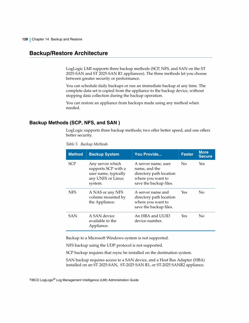
128 | Chapter 14 Backup and Restore
Backup/Restore Architecture
LogLogic LMI supports three backup methods (SCP, NFS, and SAN on the ST 2025-SAN and ST 2025-SAN R1 appliances). The three methods let you choose between greater security or performance.
You can schedule daily backups or run an immediate backup at any time. The complete data set is copied from the appliance to the backup device, without stopping data collection during the backup operation.
You can restore an appliance from backups made using any method when needed.
Backup Methods (SCP, NFS, and SAN )LogLogic supports three backup methods; two offer better speed, and one offers better security.
Backup to a Microsoft Windows system is not supported.
NFS backup using the UDP protocol is not supported.
SCP backup requires that rsync be installed on the destination system.
SAN backup requires access to a SAN device, and a Host Bus Adapter (HBA) installed on an ST 2025-SAN, ST-2025 SAN R1, or ST-2025 SANR2 appliance.
Table 5 Backup Methods
Method Backup System You Provide... Faster More Secure
SCP Any server which supports SCP with a user name, typically any UNIX or Linux system.
A server name, user name, and the directory path location where you want to save the backup files.
No Yes
NFS A NAS or any NFS volume mounted by the Appliance.
A server name and directory path location where you want to save the backup files.
Yes No
SAN A SAN device available to the Appliance.
An HBA and UUID device number.
Yes No
TIBCO LogLogic® Log Management Intelligence (LMI) Administration Guide

Backup/Restore Architecture | 129
Backup InterfacesBackup and restore are both controlled entirely through the LogLogic Appliance user interface. The only exception is that before running an SCP backup for the first time you must configure SCP via the Appliance CLI.
The Backup Configuration tab is accessible via the UI — Administration > Backup Configuration on LX, MX, and ST Appliances.
Use the Backup Configuration tab to specify settings for saving a backup copy of your Appliance log and configuration data. The default settings for backup method are None and Optimize.
Select SCP to back up any server which supports SCP with a user name, typically any UNIX or Linux system.
Select SAN to backup any volume on the Appliance to a Storage Area Network (SAN) device available to the Appliance. SAN backup is available only on a ST 2025-SAN and ST-2025 SAN R1 appliance.
A checkmark in the Optimize checkbox (the default setting) tells the Appliance to perform incremental backups instead of a full backup each time. An incremental backup copies only data that has changed since the previous backup, as opposed to a full backup which copies everything each time. These optimized backups save a lot of time for each backup, but still provide full restore capability if needed.
Bypass disk space checking — Because the LogLogic application is very conservative, and because the total space required for backing up logs is difficult to accurately predict, the system may state that not enough storage space is available for backing up your log files when in fact you know that sufficient space is available. The default condition for this checkbox is unchecked, meaning the Appliance will calculate (and possibly overestimate) the amount of backup space required. LogLogic estimates the space required based on the number of backups specified to be retained. For example, if 3 backups are specified, LogLogic estimates the disk space required for 4 backups. This is because the first (oldest) backup is deleted only after the fourth one is complete.
Placing a checkmark in the Bypass disk space checking checkbox on the Backup Configuration pane prevents the Appliance from possibly overestimating the amount of storage space necessary for a full backup of your log data.
Your backup location must support hard links.
The initial backup for the Appliance is always a full backup.
TIBCO LogLogic® Log Management Intelligence (LMI) Administration Guide

130 | Chapter 14 Backup and Restore
Placing a checkmark in Config only checkbox backs up only the configuration data on the Appliance.
You can schedule regular backups to run at a specific time regularly on any days of the week, or to run daily at that time.
What is Backed UpThe LogLogic backup process copies the configuration and real time databases, and all raw log data from the Appliance, as follows:
Table 6 Backed up Databases and Files
Backed Up Data Description
Configuration Database
A full SQL configuration database dump, created every time at the scheduled time.
Raw Log Files The general raw syslog files, representing all logs collected from the Appliance’s log sources, and stored in the Appliance's local file system.
If an Appliance is configured with a supported archiving method, for example NAS, the appliance pushes its older data such as raw syslog files, file-based log data, and indexed log data (if enabled) to the NAS volume. In this case, the backup does not copy files from your NAS server. You must copy files from your NAS server manually by evaluating your business needs and creating a plan.
LEA Certificate files
Log Export API certificates specific to the Check Point Management Interface for the Appliance.
Real Time Database
The Real Time data assembled by the Appliance based on its collected logs.
The Real Time database is much larger for LX and MX Appliances than for ST Appliances. The ST database consists of only a few tables.
TIBCO LogLogic® Log Management Intelligence (LMI) Administration Guide

Backup/Restore Architecture | 131
LogLogic backs up files on the Appliance up to the midnight before when the backup is run. That is, if you start a backup at 10 a.m. the backup captures data through the midnight ten hours prior.
The only exception is that the backup collects only through 6 hours prior. That is, if you start the backup between midnight and 6 a.m. the backup copies data through midnight the previous day, not the most recent midnight.
How Backup/Restore WorksLogLogic backup copies a complete snapshot of Appliance data to a different system, and updates that snapshot incrementally to minimize time and resource requirements for recurring backup processing.
Backup/Restore Processing
Appliance backup uses a system utility such as rsync to copy Appliance data as a complete snapshot (the image of your data at the time of backup). The utility determines the difference between the data on the Appliance and the previous backup data on the remote backup device before the data transfer.
• First backup - all data is copied
• Subsequent backups - only the difference since the previous backup is copied. This saves Appliance resources and network bandwidth. The snapshot on the backup system is updated to include the differences copied in the latest incremental backup.
Data collection continues during backup processing.
The backup system creates a directory named for the IP address of the backed-up Appliance and stores its backup data there. This allows multiple Appliances to be backed up to a backup system large enough to hold their cumulative data, as long as each Appliance has a unique IP address.
System Configuration files
• Text files related to the Appliance
• LogLogic application configuration on it
• Configuration files related to Advanced Features (Bloks, Advanced Data Model, Advanced Dashboard, and Advanced Search)
Table 6 Backed up Databases and Files
Backed Up Data Description
TIBCO LogLogic® Log Management Intelligence (LMI) Administration Guide

132 | Chapter 14 Backup and Restore
After each backup completes, both data sets (the original Appliance and the backup server data set) are identical.
• The backup program copies Appliance data to the same backup destination whenever it runs, as long as the destination device does not change. This saves space on the remote backup device by not having multiple backup copies.
• When restoring an Appliance, the backed up information is copied back to the Appliance. Processing does not continue during a restore process.
Failure Situations & Workarounds
If the Appliance crashes during a backup, the data in previous successful backups is protected. Each backup, including incremental backups, is written to a new location so no overwriting of existing backup data occurs.
LX/ST/MX Appliance Backup Differences
The backup feature functions similarly on all LogLogic Appliance product families. The only significant difference comes in the amount of disk space taken by different types of backed up data:
Performance Metric
The following equation calculates the minimum time required for a backup or restore:
data-size / network-speed = minimum-time
data-size is the total size (in MB) to backup or restore
network-speed is the network speed (in MB/second)
minimum-time is the least possible time the process takes (in seconds)
For example, the minimum time needed to back up or restore 10,000 MB (10 GB) data through a 100 Mb (12.5 MB/sec) network is:
10,000 / 12.5 = 800 sec = 13 min 20 sec
Table 7 Backup Appliance Comparison
Appliance Product Family
Configuration Database
Real Time Database
Raw Log Files
LX, MX Similar Larger Small
ST Similar Very small Very large
TIBCO LogLogic® Log Management Intelligence (LMI) Administration Guide
Backup/Restore Architecture | 133
Performance beyond this minimum time depends on many factors, including network bandwidth, and processor speed and availability.
It is good practice to use a 1 Gb interface to provide a higher network bandwidth.
Backup StorageBackups of an Appliance are typically sent to a remote backup server. For exceptionally large amounts of data, NAS external storage is attached to hold the backup data.
Solution outline with NAS external storage
Both SCP and NFS backup methods support using NAS external storage systems for storing large amounts of backup data. Adding NAS external storage to the backup system requires mounting the NAS system on the appliance to be backed up, and configuring the NAS system as instructed in that system’s documentation.
TIBCO LogLogic® Log Management Intelligence (LMI) Administration Guide

134 | Chapter 14 Backup and Restore
Backup/Restore Scenarios
There are three primary backup/restore scenarios that LogLogic LMI supports described in this section:
• Single system
• High Availability
• Disaster Recovery
These descriptions are cumulative. That is, the High Availability description details how to expand upon the single system backup/restore setup to set up High Availability backup/restore.
Single System BackupIt is good practice to schedule daily backups via the UI, at a time when network bandwidth and CPU usage are typically at a minimum. This ensures regular, complete backups that can most easily be restored from at any time if necessary.
You can backup multiple Appliances to the same backup system, as long as the backup system has sufficient space and each Appliance has a unique IP address.
Single System RestoreYou can restore a backup to the original backed-up Appliance, or to a replacement Appliance as long as the replacement Appliance has the same hardware, IP address, and software release (including maintenance releases and hotfixes) as the backed up Appliance.
For more information, see:
• SCP Backup Procedure on page 138
• NFS Backup Procedure on page 142
• SAN Backup Procedure on page 144
You can only restore a backup to an LMI appliance for which a backup configuration is already defined, and for which the backup configuration is identical to that on the backed-up appliance. For example, if the backup location was /home/john/lmi-backup and options such as Optimize or Bypass disk space checking were used on the backed-up appliance, the same location and options must be used while configuring backup on the replacement appliance.
TIBCO LogLogic® Log Management Intelligence (LMI) Administration Guide

Backup/Restore Scenarios | 135
High Availability BackupBackup and restore function similarly in a High Availability pair as they do for a single Appliance. The differences primarily involve the dynamic of having the second Appliance involved.
When a High Availability pair is initially configured, the standby Appliance automatically has backup disabled. The Master Appliance is the one that gets backed up as specified in the UI.
High Availability Restore
Restoring data to the Active Appliance is similar to a single Appliance restore. Before restoring the Active Appliance, you must disable or shutdown the Standby Appliance. Once the restore is complete, re-configure the Standby Appliance to join the HA. It should not be necessary to perform a restore to the Standby; the restored data should mirror from the Active to the Standby as part of normal High Availability mirroring.
If the Standby becomes the active appliance and you need to restore data to this new Active appliance, it should perform as a normal restore would as long as the normal restore requirements (same IP address, Appliance model, and software release) are met.
In case of an HA pair, the IP address checked is the virtual IP. Therefore, as long as the Standby appliance being used is the one from the same HA pair, it can be used to restore the backup captured originally by its peer node.
For more information, see Backup and Restore in an HA Pair on page 152.
Disaster Recovery BackupThe backup and restore features function similarly for a disaster recovery scenario as they do for either a single Appliance or High Availability Appliance pair. The differences primarily involve the placement of the backup system, the method used, and the use of tape copies.
For disaster recovery, you typically set up the backup system at a remote location separate from the Appliance being backed up. It is good practice to use the SCP backup method for disaster recovery situations because it is the more secure backup method. You must ensure that your network’s security allows access to the remote location for successful connection between the Appliance and backup system.
For optimal disaster recovery protection, copy the backup snapshot daily to magnetic tape, and secure the tapes in a separate location from the backup system.
TIBCO LogLogic® Log Management Intelligence (LMI) Administration Guide

136 | Chapter 14 Backup and Restore
Disaster Recovery Restore
Restore in a disaster recovery scenario functions similarly to restore for a single Appliance or High Availability scenario. For more information, see the preceding sections on restore the relevant scenario.
TIBCO LogLogic® Log Management Intelligence (LMI) Administration Guide

Backup Recommendations | 137
Backup Recommendations
The following are additional best practices to get the best protection for appliance data:
• Run daily backups, scheduled for a time when network bandwidth and appliance CPU usage are both at their lowest.
• When configuring backup for a disaster recovery installation, backing up to a remote location, use SCP due to its better security.
• Move a copy of the backup snapshot daily to another, more reliable location such as magnetic tape. For optimal disaster recovery protection, send the copy offsite to a secure data center.
• The following are recommended storage platforms for use with LogLogic backup:
The rsync version on the backup server must be higher or equal to the version running on the appliance, otherwise the backup process will fail. To check the rsync version run the command: rsync --version.
Table 8 Recommended Storage Platforms
NAS SCP/SSH
CentOS release 6.6 OpenSSH_5.3p1, OpenSSL 1.0.1e-fips
Do not perform backup or restore operations when data migration is in progress.
TIBCO LogLogic® Log Management Intelligence (LMI) Administration Guide

138 | Chapter 14 Backup and Restore
SCP Backup Procedure
With SCP, you can:
• Schedule regular backups to run weekly on specified days, or daily
• Designate backups as full or incremental (optimized) backups
• Run an immediate full or incremental backup
Before you can run an SCP backup, there is a one-time CLI setup you must perform.
Initial Setup for SCP BackupBefore you can use SCP backup for the first time, you must set up the SSH key using the CLI keycopy option. For details, see the system Command, page 341.
Setting up and testing the key is required for SCP backup using the UI.
In failover configurations, perform the test on both nodes.
4. In the Appliance CLI, copy the Appliance's public SSH key to the SCP server:
a. Run the system keycopy command:> system keycopy
The Appliance asks whether to test or copy the key.
b. Enter C to copy the key.
The Appliance copies the key to the SCP server and displays its pathname.
c. Note the displayed SCP server path where the key is copied. You later need to append this file to ~/.ssh/authorized_keys on the SCP server for the user’s SCP account (this must be identical to the user in step e).
The Appliance asks for the SCP server IP address.
The rsync version on the backup server must be higher or equal to the version running on the appliance, otherwise the backup process will fail. To check the rsync version run the command: rsync --version.
The actual directory that ~ maps to is different for each user, because the shell maps it to the user’s home directory based on the username that is logged in.
TIBCO LogLogic® Log Management Intelligence (LMI) Administration Guide

SCP Backup Procedure | 139
d. Enter the SCP server IP address (provided by your Administrator).
The Appliance asks for the SCP user name.
e. Enter the SCP user name (provided by your Administrator).
The Appliance asks for confirmation of the displayed host IP address and RSA key fingerprint.
f. Enter the password.
The Appliance prompts you to configure the SCP server with the Appliance’s key, appending it to -/.ssh/authorized_keys on the server.
g. Log in to the SCP server and enter the Appliance’s key in the appropriate location, for example:
SCP Server: IP-addresslogin as: scpdata=============================================================Machine Name: sqalinuxOwner: SQA AdministratorGroups: RE/SQA/DocumentationLast Update: Mar 25, 2009=============================================================SCP_server:~> ls -l /tmp/LOGLOGICPUBKEY-rw-r--r-- 1 scpdata users 611 2009-03-08 18:07 LOGLOGICPUBKEYSCP_server:~> cat /tmp/LOGLOGICPUBKEY >> ~/.ssh/authorized_keys
SCP setup is complete.
5. Verify the SCP setup.
a. Run the system keycopy command:> system keycopy
The Appliance asks whether to test or copy the key.
b. Enter T to test the key.
The Appliance asks for the SCP server IP address.
c. Enter the SCP server IP address (provided by your Administrator).
The Appliance asks for the SCP user name.
d. Enter the SCP user name (provided by your Administrator).
The Appliance copies a test file (scptestfile) to the SCP server and then copies it back to the LogLogic Appliance.
The Appliance displays when the test copies complete successfully.
6. Make sure the rsync, df, and awk utilities are installed on the SCP server. Without them, backup works but free space on the remote server is not reported.
TIBCO LogLogic® Log Management Intelligence (LMI) Administration Guide

140 | Chapter 14 Backup and Restore
Running Scheduled or Immediate SCP Backups
1. In the Appliance UI, go to Administration > Backup Configuration.
2. Select the SCP radio button.
3. (Optional) Select to Optimize the backups so only incremental backups are run instead of a full backup each time.
4. (Optional) When the Bypass disk space checking checkbox is empty (Default), the system will check for available backup space prior to backing up your log files.
5. Enter the SCP user name for User.
6. Enter the SCP server IP address for Server.
7. Set the SCP backup to automatically run on a schedule or to run immediately:
— Select the recurring Backup Schedule days and time.
Select the day(s) of the week on which you want automatic backups to occur, or select Everyday.
Set the time for the automatic backups to begin on the selected days.
— Select Start Backup Immediately.
8. Click Update to save the SCP backup configuration.
The backup process creates an additional folder using the Appliance IP address to avoid an accidental overwrite by another Appliance.
The rsync version on the backup server must be higher or equal to the version running on the appliance, otherwise the backup process will fail. To check the rsync version run the command: rsync --version.
Because the LogLogic application is very conservative, and because the total space required for backing up logs is difficult to accurately predict, the system may state that not enough storage space is available for backing up your log files when in fact you know that sufficient space is available. The default condition for this checkbox is unchecked, meaning the Appliance will calculate (and possibly overestimate) the amount of backup space required.
Placing a check in the Bypass disk space checking checkbox on the Backup Configuration pane prevents the Appliance from possibly overestimating the amount of storage space necessary for a full backup of your log data.
TIBCO LogLogic® Log Management Intelligence (LMI) Administration Guide

SCP Backup Procedure | 141
The interface displays, “Backup configuration update completed.” Appliance data is backed up daily at the beginning of the scheduled hour.
9. To optionally verify the creation of a backup directory on the SCP server for the LogLogic Appliance:
a. Log in to the SCP server.
b. In the host directory, open the backup directory (ll_bkup_ip-address) for the selected Appliance.
All backup sessions for that Appliance are contained in that backup directory. For example:
$ ls -l
total 24
drwxr-xr-x 7 root root 4096 Mar 30 11:10 .
drwxr-xr-x 3 root root 4096 Mar 27 17:11 ..
drwxr-xr-x 14 root root 4096 Mar 27 19:12 ll_bkup_session_1214586678_1238181143
drwxr-xr-x 14 root root 4096 Mar 27 21:27 ll_bkup_session_1238188349_1238189277
drwxr-xr-x 14 root root 4096 Mar 28 11:10 ll_bkup_session_1236038400_1238238608
drwxr-xr-x 14 root root 4096 Mar 29 11:09 ll_bkup_session_1238324400_1238324960
drwxr-xr-x 14 root root 4096 Mar 30 11:10 ll_bkup_session_1238410800_1238411403
TIBCO LogLogic® Log Management Intelligence (LMI) Administration Guide

142 | Chapter 14 Backup and Restore
NFS Backup Procedure
When using NFS to back up log data to a NAS or any NFS volume mounted by the Appliance, you can:
• Schedule regular backups to run weekly on specified days, or daily
• Designate backups as full or incremental (optimized) backups
• Run an immediate full or incremental backup
Running Scheduled or Immediate NFS Backups1. In the Appliance UI, go to Administration > Backup Configuration.
2. Select the NFS radio button.
3. (Optional) Select to Optimize the backups so only incremental backups are run instead of a full backup each time.
4. (Optional) When the Bypass disk space checking checkbox is empty (Default), the system will check for available backup space prior to backing up your log files.
5. Enter the NFS Server IP address.
6. Set the NFS backup to automatically run on a schedule or to run immediately:
— Select the recurring Backup Schedule days and time.
Select the day(s) of the week on which you want automatic backups to occur, or select Everyday.
Set the time for the automatic backups to begin on the selected days.
— Select Start Backup Immediately.
7. Select the number of Backups To Retain that can be available for restore, up to 30.
Because the LogLogic application is very conservative, and because the total space required for backing up logs is difficult to accurately predict, the system may state that not enough storage space is available for backing up your log files when in fact you know that sufficient space is available. The default condition for this checkbox is unchecked, meaning the Appliance will calculate (and possibly overestimate) the amount of backup space required. Placing a check in the Bypass disk space checking checkbox on the Backup Configuration pane prevents the Appliance from possibly overestimating the amount of storage space necessary for a full backup of your log data.
TIBCO LogLogic® Log Management Intelligence (LMI) Administration Guide

NFS Backup Procedure | 143
8. Click Update to save the new backup configuration.
The backup process creates an additional folder using the Appliance IP address to avoid an accidental overwrite by another Appliance.
The interface displays, “Backup configuration update completed.” Appliance data is backed up daily at the beginning of the scheduled hour.
TIBCO LogLogic® Log Management Intelligence (LMI) Administration Guide

144 | Chapter 14 Backup and Restore
SAN Backup Procedure
SAN backup is available only on ST 2025-SAN, ST 2025-SAN R1, and ST2025-SAN R2 appliances. When using SAN to back up log data to a SAN device available to the Appliance, you can:
• Schedule regular backups to run weekly on specified days, or daily
• Designate backups as full or incremental (optimized) backups
• Run an immediate full or incremental backup
Running Scheduled or Immediate SAN Backups1. In the Appliance UI, go to Administration > Backup Configuration.
2. Select the SAN radio button.
3. The SAN backup options appear.
4. (Optional) Check the Optimize checkbox to perform incremental backups instead of a full backup each time. An incremental backup copies only data that changed since the previous backup, while providing full restore capability if needed. This saves a lot of processing time for each backup after the initial backup for the Appliance.
5. (Optional) When the Bypass disk space checking checkbox is empty (Default), the system will check for available backup space prior to backing up your log files.
Because the LogLogic application is very conservative, and because the total space required for backing up logs is difficult to accurately predict, the system may state that not enough storage space is available for backing up your log files when in fact you know that sufficient space is available. The default condition for this checkbox is unchecked, meaning the Appliance will calculate (and possibly overestimate) the amount of backup space required.
Placing a check in the Bypass disk space checking checkbox on the Backup Configuration pane prevents the Appliance from possibly overestimating the amount of storage space necessary for a full backup of your log data.
TIBCO LogLogic® Log Management Intelligence (LMI) Administration Guide

SAN Backup Procedure | 145
6. In the Device pane, view the Host Bus Adapters (HBAs) and World Wide Port Number (WWPNs).
— Rollover the HBA to reveal the local port number assigned to it.
— Click + to reveal the disks attached to the HBA. Rollover disk numbers to see attached labels.
— Click a disk to display (in the Information pane) its operational Status, Size, and Linux Device mapped to it. (The UUID and Label fields are not used.)
— Click + again to reveal the disk partitions and sizes. Rollover partitions to see attached labels.
— Click a disk partition to display (in the Information pane) its operational Status, Universally Unique Identifier (UUID), Label, Size, and Linux Device mapped to it. The partition is what the user will choose to back up to, not the actual disks themselves.
— The Current Configuration window shows the target Disk and Partition selected for backing up to. If the window is blank, no Disk and Partition have been selected yet.
— To select or change the target Disk and Partition, click a partition in the Device window and roll your mouse over it to reveal the presence of a label. If no label appears, check the partition size in the Information window.
— If the partition size is adequate for backing up your log data, click the Label icon above the Device window, and enter a label for your backup. Click OK to close the window, or Cancel.
— Click the Update button at the bottom of the page. The message: Backup configuration update completed will appear at the top of the Backup Configuration page, just below the tab.
However, if you see: SAN Config: The selected device can't be used for SAN... or... SAN Config: The selected device conflicts with an existing backup/restore configuration select another partition and try again.
TIBCO LogLogic® Log Management Intelligence (LMI) Administration Guide

146 | Chapter 14 Backup and Restore
7. Set the SAN backup to automatically run on a schedule or to run immediately:
— Select the recurring Backup Schedule days and time.
— Select the day(s) of the week on which you want automatic backups to occur, or select Everyday.
— Set the Backup Time for the automatic backups to begin on the selected days.
— Select Start Backup Immediately under Backup Now.
8. Select the number of Backups To Retain that can be available for restore, from 1 to 30.
9. Click Update to save the new SAN backup configuration.
The backup process creates an additional folder using the Appliance IP address to avoid an accidental overwrite by another Appliance.
The interface displays, “Backup configuration update completed.” Appliance data is backed up daily at the beginning of the scheduled hour.
To disable backup on this Appliance, under Backup Method select None.
If the user’s SAN backup system goes offline for more than 60 seconds, it will be necessary to reboot the LogLogic Appliance after the SAN backup system is restored.
TIBCO LogLogic® Log Management Intelligence (LMI) Administration Guide

Monitoring Backup Status | 147
Monitoring Backup Status
To monitor the progress of a current backup, or review a recent backup, use Administration > Backup Configuration > Backup Status.
The Backup Status tab displays the latest backup processes and their details. The status of a backup in progress is updated every 20 seconds.
Figure 14 Backup Status
The Details column indicates the phases of the backup process as they progress. These are high-level process phases, similar to the comment fields that appear in the backup log.
To view the step-by-step detailed log of a listed backup process, including one currently processing, click its Start Time End Time entry. The complete log of the selected process appears.
Sometimes you might see a message, CAN NOT FIND EXACT MATCH MIDNIGHT DIRECTORY, in the Details column. This message is harmless and can be ignored.
TIBCO LogLogic® Log Management Intelligence (LMI) Administration Guide

148 | Chapter 14 Backup and Restore
Figure 15 Backup Status Detail Example
When the backup is completed, the end of the status details includes entries similar to:Tue Jan 17 02:02:11 2017: INFO: ###################################
Tue Jan 17 02:02:11 2017: INFO: # Trim excess backup on remote host
Tue Jan 17 02:02:11 2017: INFO: ###################################
Tue Jan 17 02:02:11 2017: INFO: Executing command "/usr/bin/ssh -p 22 [email protected] '\ls -1 /loglogic/backup/ll_bkup_::ffff:192.168.1.252' 2>&1"
Tue Jan 17 02:02:11 2017: INFO: Executing command "/usr/bin/ssh -p 22 [email protected] 'mv /loglogic/backup/ll_bkup_::ffff:192.168.1.252/ll_bkup_session_6.1.0_1484618400_0 /loglogic/backup/ll_bkup_::ffff:192.168.1.252/ll_bkup_session_6.1.0_1484618400_1484618531' &> /dev/null"
Tue Jan 17 02:02:12 2017: INFO: ###################################
Tue Jan 17 02:02:12 2017: INFO: # Backup Completed
Tue Jan 17 02:02:12 2017: INFO: ###################################
Tue Jan 17 02:02:12 2017: INFO: Executing command "rm -rf /loglogic/backup_prep/staging &> /dev/null"
TIBCO LogLogic® Log Management Intelligence (LMI) Administration Guide

Monitoring Backup Status | 149
Backup ErrorsBecause the backup is live, data is modified while the backup is running. This might cause some system utility errors which are reported in the backup status.
Whenever the backup process encounters an error, the backup process stops; it does not retry the action that caused the error. If the Appliance repeatedly reports errors during backup, run the backup at a different time when the CPU and network bandwidth are less busy.
The system utility error “Partial transfer due to vanished sources files” is expected because source files are archived or purged due to retention, often as part of Appliance maintenance. If the backup runs during the regular Appliance maintenance cycle, it encounters this error.
TIBCO LogLogic® Log Management Intelligence (LMI) Administration Guide

150 | Chapter 14 Backup and Restore
Restoring an Appliance
To restore an available backup to the Appliance, use the Restore Configuration tab.
For more information, see:
• SCP Backup Procedure on page 138
• NFS Backup Procedure on page 142
• SAN Backup Procedure on page 144
Performing a restore overwrites the current log and configuration data on the Appliance with the data stored in the backup. Data is automatically restored using the method (NFS or SCP) in which it was backed up.
Data can be restored to any Appliance, including the Appliance from which it was backed up. However, if your intention is to move data between Appliances, It is good practice to use the data migration feature and not backup and restore. For more information, see Chapter 27, Migrating Data Between Appliances, on page 299.
You can only restore a backup to an LMI appliance for which a backup configuration is already defined, and for which the backup configuration is identical to that on the backed-up appliance. For example, if the backup location was /home/john/lmi-backup and options such as Optimize or Bypass disk space checking were used on the backed-up appliance, the same location and options must be used while configuring backup on the replacement appliance.
Restoring from a backup, which was taken with an older version of LMI than the current version, is not supported.
When restoring to a new Appliance, it must have the same IP address of the Appliance from which you originally ran the backup.
The rsync version on the backup server must be higher or equal to the version running on the appliance, otherwise the backup process will fail. To check the rsync version run the command: rsync --version.
TIBCO LogLogic® Log Management Intelligence (LMI) Administration Guide

Restoring an Appliance | 151
The Restore Configuration tab Source drop-down menu lists all available backups from which a restore can be performed. If no backups are available, the only menu entry is NULL.
Figure 16 Restore Configuration
1. Go to the Administration > Backup Configuration > Restore Configuration tab.
2. In the Source drop-down menu, select the backup from which you want to restore Appliance data.
3. Click the Restore button.
4. A confirmation dialogue appears.
5. Click the Confirm button.
If you check the Config only checkbox on the Backup Configuration tab, the Source list displays “config only backups”. If the Config only checkbox is not selected, this list displays full backups.
TIBCO LogLogic® Log Management Intelligence (LMI) Administration Guide

152 | Chapter 14 Backup and Restore
Backup and Restore in an HA Pair
Backing up an HA pair is similar to backing up a single appliance. Configure the backup to use the public IP address.
Restoring an HA PairTo restore a backup to both Appliances in a high availability (HA) pair, you must use a different restore procedure:
1. From the CLI, use the set failover disable command on the Standby Appliance in the HA pair to remove it from the pair.
2. Using HA pair’s virtual IP, restore from the backup as described in , Restoring an Appliance, on page 150.
3. Use the set failover configure command on Standby Appliance to configure the Standby Appliance to rejoin the HA pair.
When prompted This appliance shall be the destination of the initial data migration, enter:
Y
Once failover is configured and the migration completes, the HA pair is available with the restored data on both Appliances.
TIBCO LogLogic® Log Management Intelligence (LMI) Administration Guide

| 153
Chapter 15 Viewing Archived Data
Topics
• Viewing Archived Data Files on page 154
• Verifying the SHA Digest on Data Files on page 154
• Listing Archived Passive (Non-Parseable) Files on page 155
TIBCO LogLogic® Log Management Intelligence (LMI) Administration Guide

154 | Chapter 15 Viewing Archived Data
Viewing Archived Data
Administration > Data Files lets you view all archived data files.
Because data files are compressed, you must save them to a local machine and decompress them for viewing. When you click a Data File Name, the Appliance initiates a file download to your local system.
Viewing Archived Data FilesThe Data Files page lists all archived data files. The Appliance archives data on an ongoing, hourly basis. To download and view a data file, click its file name.
To view a Data File
1. To limit the list of data files by time, select the year, month, day, and time to view.
2. Click on the Data File Name for the file you want to view.
3. The Appliance downloads the data file to your local machine.
4. Unzip the downloaded file.
5. Open the downloaded file in a text editor.
For information about for each data file on the Data Files page, see the online Help.
Verifying the SHA Digest on Data FilesLogLogic lets you verify the integrity of your data files by verifying that the SHA Digest has not changed since the LogLogic Appliance captured the data. Use the Data Files page to verify the SHA Digest. (See the CLI section for information on setting the Appliance Digest.)
To verify the SHA Digest on data files
1. In the navigation menu, click Administration > Data Files.
2. The Data Files page appears.
To further ensure the integrity of data on an ST Appliance, consider using a WORM (write once read many) storage server such as Network Appliance’s SnapLock.
TIBCO LogLogic® Log Management Intelligence (LMI) Administration Guide

Viewing Archived Data | 155
3. Click the checkbox to the left of each data file to verify.
4. Click Verify to start the verification process.
When verification completes, a flag appears in the Digest Verified column:
— A green flag indicates successful verification of the data files’s Digest. The timestamp next to the green flag identifies the date and time the verification succeeded.
— A red flag indicates failed verification. Mouse over the failure message for more information on the reason. A failure can mean:
The file was modified. Mouse over the failure to view the new Digest.
The file is no longer accessible. The file might be inaccessible for various reasons such as the location of the file has changed or the network connection is down and your file is on a storage server such as a NAS or Centera.
Listing Archived Passive (Non-Parseable) FilesThe Data Files page lists all archived data files. The Appliance archives data on an ongoing, hourly basis. To download and view a data file, click its file name.
To view a Data File
1. To limit the list of data files by time, select the year, month, day, and time to view.
2. Click on the Data File Name for the file you want to view.
3. The Appliance downloads the data file to your local machine.
4. Open the downloaded file in a text editor.
The verification process has a low priority in the Appliance. If the system is busy processing log data, the verification process might take longer than expected.
TIBCO LogLogic® Log Management Intelligence (LMI) Administration Guide

156 | Chapter 15 Viewing Archived Data
TIBCO LogLogic® Log Management Intelligence (LMI) Administration Guide

| 157
Chapter 16 Archiving Log Data (ST and EVA Only)
To extend the storage capacity of an ST or EVA Appliance, you can enable archiving by attaching a NAS or EMC Centera storage server to the ST or EVA appliance, or set up a SAN device for the ST 2025-SAN, ST 2025-SAN R1,or ST 2025-SAN R2 appliances. This lets you archive log data to a remote storage device to free up local storage space on the appliance to use for incoming log data.
When configured with an ST or EVA appliance, a NAS server acts as a data storage extension where log data can be accessed as if it were still on the appliance. Therefore, the same access to reporting, indexing, searching, and alerting exists on the storage server as on the appliance itself.
Centera, on the other hand, does not use a mount point and does not accept indexes. The appliance does not report alerts for Centera volumes. You can only run regex searches when connected to the Centera servers, because LMI pulls each individual BFQ data file over to examine what the search is configured for, until it has fulfilled the timespan and then displays the results.
You can add a NAS or Centera server to an ST or EVA appliance from the Administration > Archive Configuration menu.
Topics
• How Archive Storage Works on page 158
• Configuring NAS Server Storage on page 164
• Configuring SAN Archive Storage on page 166
• Configuring EMC Centera Storage on page 168
TIBCO LogLogic® Log Management Intelligence (LMI) Administration Guide

158 | Chapter 16 Archiving Log Data (ST and EVA Only)
How Archive Storage Works
The archive process copies the files to the SAN, NAS, or Centera server and updates the database.
Archiving to NAS server
If the DAS capacity reaches the maximum threshold or if the files reach their retention time limit, the files are deleted. Using SnapLock for your NAS server, all archived raw data files are protected and cannot be purged from the NAS server.
By default, the node ID is not used in the file system path for archiving. You must enable it if required. See Enabling a node ID in the archive path.
Archiving to Centera server
Centera is not affected by the local DAS size. It archives immediately and the BFQ file exists on both machines for a small period of time, after which LMI removes it from the appliance based on settings such as local retention policy and disk space usage.
Archive Preference
Until LMI 6.1.0, the archiver archived the oldest data files first, by default. Starting LMI 6.1.1, the user can choose between archiving the oldest files first, the largest files first, or a combination of the two.
An archiving pass involves moving some data files followed by moving some index folders, and then cycling back to data files. Considering larger files as part of archiving can have the effect of freeing up disk space more quickly.
In case of NAS server, LMI owns the contents of the archival top directory, if one archive volume is: 1.2.3.4:/Volume_1/my_archive/
Every file under my_archive/ comes from the archival process.
For a given set of files, this configuration does not change the overall time to move all the files. It only frees up the most disk space earlier in the process due to moving the largest files earlier in the process.
TIBCO LogLogic® Log Management Intelligence (LMI) Administration Guide

How Archive Storage Works | 159
The following parameters must be configured for this feature:
Examples
• Setting numFilesPerArchiveIter=10, numFilesBySizePerArchiveIter=10
will archive the 10 oldest files, followed by the 10 largest files per archiving pass.
• Setting numFilesPerArchiveIter=10, numFilesBySizePerArchiveIter=0
will archive only the 10 oldest files per archiving pass.
• Setting numFilesPerArchiveIter=0, numFilesBySizePerArchiveIter=10
will archive only the 10 largest files per archiving pass.
To change the archive settings:
1. Open the /loglogic/conf/archiver.conf file. Create the file if it does not exist.
2. Add or change the lines as in the following example:numFilesPerArchiveIter=5
numFilesBySizePerArchiveIter=5
Index ArchivingBy default, both raw data and indexed data is archived. Under some circumstances, an appliance would archive all indexed data to remote storage.
If you want to optimize index searches and you have archiving enabled, you can disable index archiving to ensure that indexed data remains on local storage.
Property Default Value Description
numFilesPerArchiveIter 5 The number of files to archive per archiving pass, based on time - the oldest files are archived first
numFilesBySizePerArchiveIter 5 The number of files to archive per archiving pass, based on size - the largest files are archived first.
The = sign must immediately follow the property name. No additional space should be entered.
TIBCO LogLogic® Log Management Intelligence (LMI) Administration Guide

160 | Chapter 16 Archiving Log Data (ST and EVA Only)
To disable index archiving:
1. Create the /loglogic/conf/archiver.conf file, if it does not exist.
2. Add the following line in the file:numIndexFilesPerArchiveIter=0
3. Save the file.
4. Restart the engine_archive, or stop and start mtask.
Storage Volume WatermarksPertaining to NAS/SAN storage and LogLogic local disk storage (DAS), three watermark thresholds in the /loglogic/conf/archive_config file determine how log storage is treated on these devices.
These three watermark thresholds are described as follows.
1. The localVolHighWatermark watermark pertains to the Appliance local volume (DAS). If the percentage of used local disk space (on the /loglogic partition) exceeds the specified watermark threshold, the Appliance starts incrementally deleting the files with the earliest expiration date from the DAS to accommodate new data.
If everything is set to the same expiration policy (for example, 1 year), then the oldest file is purged. However, when an appliance is configured with multiple different retention policies, files with the earliest expiration date are purged first. For example, files that are set to expire in one week are deleted under emergency purging circumstances before files that expire after one year and 10 months.
Typically, this threshold should not be reached when connected to a NAS/SAN, because another watermark, localVolHighArchiveWatermark, , triggers the engine_archive to begin archiving files off the DAS and over to the NAS/SAN server, thus keeping the local DAS disk space relatively free.
However, if the NAS/SAN is not configured properly or if the network is not available, it is possible that the local logs will not be archived (moved) and the local /loglogic partition can become full. Therefore this localVolHighWatermark watermark prevents an undesirable full partition by beginning the file deletion process once the watermark is reached.
This watermark value can be adjusted from 0% to 99%.
These thresholds are not applicable to Centera. For information on Centera, see Configuring EMC Centera Storage, page 168.
TIBCO LogLogic® Log Management Intelligence (LMI) Administration Guide

How Archive Storage Works | 161
2. The localVolHighArchiveWatermark watermark is the other watermark threshold pertaining to the appliance local volume DAS. If the percentage of used local disk space on the /loglogic partition exceeds this specified threshold, the appliance starts incrementally archiving the oldest files to the specified NAS/SAN server. This archiving process effectively performs a move operation. Although files are copied temporarily, they ultimately only exist on archive storage after all operations are performed for a given file, thus freeing up space on the DAS. This is considered an effective move operation because a copy operation is used to transfer data to the archive storage, followed by a delete operation to remove the local copies of the file. This ensures a safer data transfer than using a formal move command..
This watermark value can be adjusted from 2% to 94% with a default level of 75%.
3. The nasVolLowWatermark watermark pertains to the NAS/SAN volume storage. If the available disk space on the NAS/SAN device goes below this specified threshold, the appliance starts incrementally deleting the files with the earliest expiration date on the NAS/SAN volume to accommodate new data.
This NAS/SAN Volume Low Watermark value can be adjusted from 10 GB to 1024 GB with a default level of 20 GB x the number of mounting points set (up to 32). It is specified in gigabytes instead of a percentage, because a percentage on a NAS/SAN can vary greatly in actual disk space. For example, if the user
Immediate Archiving: Setting this watermark to a very low value (localVolHighArchiveWatermark=2) triggers immediate archiving when the NAS/SAN volume is successfully mounted. On a new appliance the disk usage of 1% or 2% is not low enough to trigger immediate archiving, but after the appliance has collected more data, immediate archiving is triggered.
Setting the archiving threshold to a value below 5% might increase the chance of interference between the indexer and the archiver processes, and FileNotFoundException messages in indexer.log might be displayed. This is because, as soon as files are collected in the LogLogic LMI appliance, the archiving process starts moving files while the indexer is trying to access them. The lower the archiving threshold, the greater is the chance of interference.
TIBCO LogLogic® Log Management Intelligence (LMI) Administration Guide

162 | Chapter 16 Archiving Log Data (ST and EVA Only)
has two mounting points for NAS, the NAS Volume Low Watermark value will be changed to 2x20 GB=40 GB instead of only 20 GB.
NAS SnapLock ProtectionFor additional protection, LogLogic lets you configure the Appliance to use Network Appliance’s SnapLock™ software. If you enable SnapLock for your Network Appliance NAS Server, all archived raw data is protected and cannot be modified for the time period defined by your data retention settings. Index files are not locked. If SnapLock is enabled, you cannot purge protected files from the NAS server, so make sure you have a enough available space to handle the archiving from the appliance.
External Storage in an HA PairExternal storage for ST and EVA appliances is not replicated as part of the failover configuration. When an appliance fails over, its external storage is automatically switched over to the standby appliance as it becomes active.
Enabling a node ID in the archive path
1. Create the archive configuration file archive_config under the /loglogic/conf directory.
2. Add the following line to the file:
archivedPathWithId=1
Up to 256TB of aggregate archive space is supported across up to 32 mount points. If you have already connected the appliance to a SAN or a NAS server and then want to change the threshold or the mount directory, you will no longer have access to your stored data.
By reverting the configuration to the old archive storage information, you can access the data again.
On the NAS server, you must create a directory as a file share for the appliance to mount, with rw, no_root_squash access permission.
If you reduce or extend the data retention settings for your archived data, the new retention time applies only to the new files that are SnapLock enabled. All archived data files on the NAS prior to the change in retention time retain their existing retention time settings.
TIBCO LogLogic® Log Management Intelligence (LMI) Administration Guide

How Archive Storage Works | 163
3. Restart the engine_archive.
For more information and instructions on configuring external storage for an ST or EVA appliance in an HA pair, see , Failover and External Storage, on page 277.
This setting is not persisted on upgrades if enabled through LMI 5.6.2HF3 or later, or 5.7.0.
Starting LMI 6.1.0, archiving with and without the node ID is supported. However, the setting is disabled for new installations and after an upgrade. Hence, if you have been using this feature in prior versions, you must create the archive_config file before upgrading to LMI 6.1.0 or later.
If you were not using this feature in prior versions and want to use it after the upgrade, you must re-enable the setting after the upgrade is complete.
TIBCO LogLogic® Log Management Intelligence (LMI) Administration Guide

164 | Chapter 16 Archiving Log Data (ST and EVA Only)
Configuring NAS Server Storage
You can use a NAS server in conjunction with a LogLogic ST or EVA appliance as a dedicated storage system for raw data files. See NAS SnapLock Protection, page 162.
To enable a NAS Server as dedicated storage:
1. In the navigation menu on the appliance, select Administration > Archive Configuration.
2. Select the Enable NAS radio button to activate the NAS server you specify.
3. In the NAS Configuration field, click Add and enter the NAS server IP address and mount directory.
You must create the directory on the NAS server before you can mount the machine. The Appliance can be connected to up to 32 mount points.
For example, the format for the IP address and mount directory is:
xxx.yyy.zzz.ddd:/volume_N
where
xxx.yyy.zzz.ddd is the IP address for the NAS server
volume_N is the mount directory
Archive Threshold relates to local storage capacity of the Appliance. The user can change the default setting (75% of max) at which point the oldest files stored on the Appliance will begin moving to the external archive storage device (until the Archive Threshold value is met again).
Setting the archiving threshold to a value below 5% might increase the chance of interference between the indexer and the archiver processes, and FileNotFoundException messages in indexer.log might be displayed. This is because, as soon as files are collected in the LogLogic LMI appliance, the archiving process starts moving files while the indexer is trying to access them. The lower the archiving threshold, the greater is the chance of interference.
The NAS Server field is case sensitive and format specific. If the same file name and path exists, the data is overwritten. If you designate a partition and change it later, you might not be able to access the files you saved on the old partition. In addition, if this is the first time you are specifying an archive server, make sure the mount directory is empty.
TIBCO LogLogic® Log Management Intelligence (LMI) Administration Guide

Configuring NAS Server Storage | 165
4. Select the Enable SnapLock checkbox to let the Appliance archive data to a Network Appliance Server with SnapLock.
5. Click Update to save your settings.
TIBCO LogLogic® Log Management Intelligence (LMI) Administration Guide

166 | Chapter 16 Archiving Log Data (ST and EVA Only)
Configuring SAN Archive Storage
A Storage Area Network (SAN) device can be attached to the appliance as a dedicated and secure storage system for your log data files, providing a suitable Host Bus Adapter is fitted to your appliance.
When using the archive feature in a HA configuration ensure that SCSI reservations have been enabled on your SAN Appliance.
To enable a SAN archive device
1. In the navigation menu on the appliance, select Administration > Archive Configuration.
2. Select the Enable SAN radio button.
3. In the Device pane, view the Host Bus Adapters (HBAs) and World Wide Port Number (WWPNs).
— Rollover the HBA to reveal the local port number assigned to it.
— Click + to reveal the disks attached to the HBA. Rollover disk numbers to see attached labels.
— Click a disk to display (in the Information pane) its operational Status, Size, and Linux Device mapped to it. (The UUID and Label fields are not used.)
— Click + again to reveal the disk partitions and sizes. Rollover partitions to see attached labels.
— Click a disk partition to display (in the Information pane) its operational Status, Universally Unique Identifier (UUID), Label, Size, and Linux Device mapped to it. The partition is what the user will choose to back up to, not the actual disks themselves.
— The Current Configuration window shows the target Disk and Partition selected for backing up to. If the window is blank, no Disk and Partition have been selected yet.
— To select or change the target Disk and Partition, click a partition in the Device window and roll your mouse over it to reveal the presence of a
If the SAN administrator who published the LUN for you did not partition it, the + is not displayed. To partition it, see the Knowledge Base article #000029103
TIBCO LogLogic® Log Management Intelligence (LMI) Administration Guide
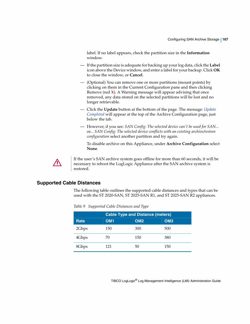
Configuring SAN Archive Storage | 167
label. If no label appears, check the partition size in the Information window.
— If the partition size is adequate for backing up your log data, click the Label icon above the Device window, and enter a label for your backup. Click OK to close the window, or Cancel.
— (Optional) You can remove one or more partitions (mount points) by clicking on them in the Current Configuration pane and then clicking Remove (red X). A Warning message will appear advising that once removed, any data stored on the selected partitions will be lost and no longer retrievable.
— Click the Update button at the bottom of the page. The message: Update Completed will appear at the top of the Archive Configuration page, just below the tab.
— However, if you see: SAN Config: The selected device can't be used for SAN... or... SAN Config: The selected device conflicts with an existing archive/restore configuration select another partition and try again.
To disable archive on this Appliance, under Archive Configuration select None.
Supported Cable DistancesThe following table outlines the supported cable distances and types that can be used with the ST 2020-SAN, ST 2025-SAN R1, and ST 2025-SAN R2 appliances.
If the user’s SAN archive system goes offline for more than 60 seconds, it will be necessary to reboot the LogLogic Appliance after the SAN archive system is restored.
Table 9 Supported Cable Distances and Type
Cable Type and Distance (meters)
Rate OM1 OM2 OM3
2Gbps 150 300 500
4Gbps 70 150 380
8Gbps 121 50 150
TIBCO LogLogic® Log Management Intelligence (LMI) Administration Guide

168 | Chapter 16 Archiving Log Data (ST and EVA Only)
Configuring EMC Centera Storage
EMC Centera can be used in conjunction with a LogLogic ST or EVA appliance as a dedicated and secure storage system for raw data files.
To enable an EMC Centera Server:
1. In the navigation menu on an ST or EVA appliance, select Administration > Archive Configuration > Centera Configuration.
2. Select the Enable Centera check box to enable communication between the LogLogic Appliance and the Centera storage device.
3. Designate at least one Centera storage device IP address to enable your Centera connection.
4. Pool IPs are the IP address(es) of the Centera storage device(s) to which you back up data. You must designate at least one Centera storage device IP address to enable the Centera connection. You can designate up to 18 IP addresses. You can specify an IP address for each port. The default port is 3218.
5. Select the Retention method to use.
This option lets you specify either a Centera defined Retention Class, or an Appliance specified retention period.
Options include:
— Class - Enter a Centera Class defined by your Centera administrator.
— Period - Specify a length of time you want to store your data on the Centera storage device. You can specify a period from one month to 10 years and 11 months. Period is the default option.
6. Select your Authentication method.
This lets you specify alternate methods for authenticating the Appliance to the Centera device. Options include:
— None - Do not use any authentication method to back up your data.
— Username and Password - Designate a user name and password for authentication. Your system administrator creates the user name and password.
— File - Designate a specific path to back up your data on the Centera storage device. The path must be the full path on your LogLogic Appliance. Your system administrator provides the .pea file for this option. Cut and paste the file in the provided text box.
TIBCO LogLogic® Log Management Intelligence (LMI) Administration Guide

Configuring EMC Centera Storage | 169
7. Click Update.
This option saves and updates the information on the Centera Configuration page. Clicking this button automatically saves and updates your data on Centera. If the update is successful, a confirmation appears at the top of this page.
8. Click Status to view the Centera Status page.
If you click Update and then Status, you can view your changes on the Centera Status page.
TIBCO LogLogic® Log Management Intelligence (LMI) Administration Guide

170 | Chapter 16 Archiving Log Data (ST and EVA Only)
TIBCO LogLogic® Log Management Intelligence (LMI) Administration Guide

| 171
Chapter 17 Managing Data Retention Rules
This feature allows administrator to manage the time duration for which data will be retained on the Appliance. Multiple Data Retention rules can be defined for managing the data.
Topics
• Data Retention Overview on page 172
• Viewing Retention Rule Details on page 173
• Creating a New Retention Rule on page 174
• Modifying Rule Settings on page 175
• Deleting a Custom Rule on page 178
TIBCO LogLogic® Log Management Intelligence (LMI) Administration Guide
172 | Chapter 17 Managing Data Retention Rules
Data Retention Overview
The Raw data retention time is the duration for which the data will be retained on the Appliance. The Indexed data retention time is the duration for which the raw data will be indexed for searching.
Use the Administration > Data Retention tab to define Data Retention rules. For each rule, you can specify the retention time period for raw and indexed data. The maximum value of indexed data retention can be 10 years. Log sources should be assigned to a specific Retention rule.
During installation, some pre-defined Retention rules (1 Default and multiple Custom rules) are created. The number of pre-defined Custom rules may vary depending on each Appliance model. You can create new Custom Retention rules. The Custom rules are prioritized in the order as they appear (from highest on the top) in the Custom rules list. You can change the priority by moving them up/down in the Custom Rules list, see , Prioritizing the Custom Rules, on page 176.
• View All Rules—Lists all log sources and their effective rules. You can view the effective rule for a particular log source. For details, see , Viewing Retention Rule Details, on page 173.
• Custom Retention Rules—Specifies the raw and indexed data retention time for log sources assigned to the custom rule. For details on how to assign log sources to the rule, see Assigning Log Sources to a Data Retention Rule on page 175.
• Default Retention Rule—Specifies the raw and indexed data retention time for log sources that have not been assigned to any custom rule. If any log source is not assigned to Custom Retention rule, it will automatically be assigned to the Default Retention rule. You can modify the time period, however, you cannot delete this rule. For details, see Viewing Retention Rule Details on page 173.
You must have the System Configuration privileges and the Access all devices in the appliance checkbox enabled to manage Data Retention rules for any Appliance.
• During installation, the default Raw data retention period is set to 90 days for LX; 365 days for MX; 365 days for ST Appliance. The Indexed data retention period may vary.
• Similarly, all log sources will be pre-assigned to the Default Retention rule.
TIBCO LogLogic® Log Management Intelligence (LMI) Administration Guide

Viewing Retention Rule Details | 173
Viewing Retention Rule Details
The Custom rule specifies the raw and indexed data retention time for log sources assigned to the custom rule. You can create, modify, or delete custom rules.
The Default rule applies to all log sources that are not assigned to any custom rules. You can modify the time period, however, you cannot delete this rule.
To view Retention Rule Details
1. Navigate to Administration > Data Retention. The Data Retention window appears.
The left pane of the screen displays all rules including the default rule, and pre-defined custom rules. Once you select a rule, the right pane displays the rule details.
2. To view all rules, click View All Rules in the left pane. You can view every log source and it’s effective rule in the right pane.
3. From the left pane, select a rule. The right pane displays the rule description, and a list of all log sources assigned to the selected rule.
You can filter the device list by Groups and devices or Only groups. You can also filter the list by entering text in the Find field, and press Enter. The filtered list containing the search term is displayed.
4. Clear the search term in the Find field and press Enter to see all log sources.
You may resize and move the columns to the positions you prefer by clicking on them and dragging. To sort the column in descending or ascending order, click the column header.
TIBCO LogLogic® Log Management Intelligence (LMI) Administration Guide

174 | Chapter 17 Managing Data Retention Rules
Creating a New Retention Rule
You can create new retention rules to specify the retention time period for specified log sources. Once you create a new retention rule, to assign log sources to this rule, see , Assigning Log Sources to a Data Retention Rule, on page 175.
To Create a New Retention Rule
1. Access Administration > Data Retention from the navigation menu.
2. Click the Create New button from the left pane, to create a new retention rule. The New Retention Rule window appears.
3. Enter the Name, and Description of the rule.
4. In the Raw Data Retention time section, select the time period for the raw data from the months, and days drop-down menus.
5. To enable indexing, click the Index the data (for searching) checkbox.
6. When you select the Index the data (for searching) checkbox, the Indexed Data Retention time section is displayed. Select the time period for retaining the indexed data.
7. Click Save to save the rule settings. The new rule is now listed in the Custom Rules list in the left pane.
8. Click the Commit Changes button to commit the latest changes. Click the Revert Changes button to revert to the last committed changes.
The maximum raw data retention period for all appliance models is 10 years.
You must select the Data Retention time period from the drop-down menu. The Indexed Data Retention time period cannot be more than Raw Data Retention time period.
Once you make all changes, click the Commit Changes button to commit to all changes. Once you click the Commit Changes button, the new data will be stored as per the new rule.
TIBCO LogLogic® Log Management Intelligence (LMI) Administration Guide

Modifying Rule Settings | 175
Modifying Rule Settings
To Edit Rule Settings
1. Click the icon to edit the retention rule. The Edit Retention Rule window appears.
2. Make the appropriate changes.
3. Click the Save button to save the new settings.
4. Click the Commit Changes button to commit the latest changes. Click the Revert Changes button to revert to the last committed changes.
Assigning Log Sources to a Data Retention RuleYou can assign log sources to a Data Retention rule at any time. Once you assign a log source to a particular Retention rule, the log source will acquire the Retention time settings of the rule.
To Assign Log Sources to a Data Retention Rule
1. Select a rule from the rule list or click the View All Rules button. Make sure that the desired log source is listed on the right pane.
2. Select the log source from the list and drag it to a different rule in the left pane. Press the Shift or Ctrl key to select multiple log sources from the list. The confirmation window appears.
3. Click Yes in the confirmation window to change the data retention rule for the specified log source.
The maximum raw data retention period for all appliance models is 10 years.
Once you make all changes, click the Commit Changes button to commit to all changes. Once you click the Commit Changes button, the new data will be stored as per the new rule.
TIBCO LogLogic® Log Management Intelligence (LMI) Administration Guide

176 | Chapter 17 Managing Data Retention Rules
4. Click the Commit Changes button to commit the latest changes. The new data retention time will be applied to the selected log source. Click the Revert Changes button to revert to the last committed changes.
Prioritizing the Custom RulesThe Custom Rules are prioritized in the order as they are displayed (from highest on the top) in the Custom Rules list. The priority of rule determines the Retention rule that is applied to which log source. You can change the priority of custom rules by moving them up/down in the Custom Rules list.
To view the Retention rule that is applied to a device or group, click the View All Rules button. The screen displays the Effective Rule for every device and device group. The Effective Rule Name column displays the Rule that is in effect after considering rule prioritization.
An Example of Prioritizing Retention Rules
1. We created two Custom Retention Rules named RR1Week and RR3Months that have Raw Data Retention period of 1 Week and 3 Months respectively.
2. Then the device group named Windows Machines is assigned to the RR1Week retention rule.
3. Similarly, a log source named FrontDesk1 is assigned to the RR3Months retention rule. Note that the FrontDesk1 is also part of the device group Windows Machines.
4. Since FrontDesk1 is assigned to the RR3Months retention rule with a retention time of 3 Months and is also a part of the group Windows Machines with a retention time of 1 Week, to decide the Effective Retention Rule (i.e. the retention time applicable to the data received from FrontDesk1) the system will use the data retention rule priorities. If the rule RR1Week is prioritized higher, then the Effective rule for FrontDesk1 will be RR1Week.
5. However, if the rule RR3Months is prioritized higher, then the Effective rule for FrontDesk1 will be RR3Months.
Once you make all changes, click the Commit Changes button to commit to all changes. Once you click the Commit Changes button, the new data will be stored as per the new rule. The retention policy of data already stored on the appliance for the log source does not change.
TIBCO LogLogic® Log Management Intelligence (LMI) Administration Guide

Modifying Rule Settings | 177
To Prioritize the Custom Rule
1. From the left pane, select the Custom rule from the custom rule list. Using the drag-drop method, re-arrange the custom Rules in the priority order. The Change the Priority confirmation window appears.
2. Click Yes in the confirmation window to change the priority of the selected rule. The Rules will be prioritized in the order they are displayed (highest on the top).
3. Click the Commit Changes button to commit the latest changes. Click the Revert Changes button to revert to the last committed changes.
Once you make all changes, click the Commit Changes button to commit to all changes. Once you click the Commit Changes button, the new data will be stored as per the new rule.
TIBCO LogLogic® Log Management Intelligence (LMI) Administration Guide

178 | Chapter 17 Managing Data Retention Rules
Deleting a Custom Rule
To Delete an Existing Custom Rule
1. Click the icon to delete the retention rule. The Delete Rule confirmation window appears.
2. Click Yes in the confirmation window to delete the selected rule. All log sources under this rule will be automatically moved to the Default Retention Rule.
3. Click the Commit Changes button to commit the latest changes. Click the Revert Changes button to revert the last committed changes.
Once you make all changes, click the Commit Changes button to commit to all changes. Once you click the Commit Changes button, the new data will be stored as per the new rule.
TIBCO LogLogic® Log Management Intelligence (LMI) Administration Guide
| 179
Chapter 18 Working with Suites
Suites let you group alert rules, custom reports, and search filters together. This lets you:
• Import and export all the components together between Appliances in a single “suite”
• Access all Suite components from a single location in the user interface
For example, if you are using one of the TIBCO LogLogic® Compliance Suites such as the Sarbanes-Oxley Edition, you can manage or use all its pre-Suited components from inside Suites.
A Suite can consist of alerts, custom reports, search filters, or any combination of these components.
Suites also help to copy or move groups of components to other Appliances using the import and export functionality. For more information on importing and exporting Suites, see Chapter 19, Import/Export Entities Between Appliances, on page 187.
Topics
• Managing Suites on page 180
• Creating a Suite on page 182
• Modifying a Suite on page 184
You have the same manageability of components when accessed in a Suite as you do when accessing them as standalone entities.
TIBCO LogLogic® Log Management Intelligence (LMI) Administration Guide

180 | Chapter 18 Working with Suites
Managing Suites
The main Suites page lists all Suites in the LogLogic Appliance as well as the number of alerts, reports, and search filters in each Suite. You can access all Suites and their corresponding components from this view.
You can choose to list the reports in a Suite in the Reports/Search navigation menus. When viewing the reports in a Suite from the Reports/Search view, you can run each report ad-hoc or update the report. When you update the report, the changes affect all Suites containing the report. For more information on how to list reports under the Reports/Search navigation menus, see Creating a Suite on page 182.
To add a new Suite to the Appliance, click Add New. The Suites page appears.
To modify the details for an existing Suite on the Appliance, such as the name, description, sharing, and listing under Reports/Search menus, click the Suite Name.
To remove a Suite from the Appliance, check the Suite’s checkbox and then click Remove.
The Suite tab also displays whether each Suite is checkmarked as Shared (Share with Other Users), and whether the Suite is checkmarked as Listed (List under Reports/Search) in the navigation menus.
When you install a TIBCO LogLogic® Log Source Package (LSP), you can also import the Suite of alert rules, custom reports, and search filters if one comes with the LSP. However, Management > Suites cannot be used for installing the LSP itself. You must follow the installation procedure in the TIBCO LogLogic® Log Source Packages (LSP) Release Notes.
To access or modify Click the number in...
Alerts in the Suite the Alerts column
Custom Reports in the Suite the Reports column
Search filters in the Suite the Search Filters column
TIBCO LogLogic® Log Management Intelligence (LMI) Administration Guide

Managing Suites | 181
To view existing Suites
1. In the navigation menu, click Management > Suites.
The Suites page appears. The page displays the details about the existing Suites including the number of associated alerts, reports, and search filters, a description, the owner, and if the reports are listed under Reports/Search menus as a Suite.
2. To view details about the Suite such as the alerts, reports, or search filters, click the number in the appropriate column for the Suite you want to view.
You can also click on a Suite name, and then click the appropriate tab for Alerts, Reports, or Search Filters.
To view existing reports listed as a Suite in the Navigation Menu
1. In the navigation menu, click Reports.
2. The menu expands, listing all Report types and Report sub-categories.
3. Click on a Report sub-category (for example: Reports > Access Control > User Access) to view all Saved Reports that have been checkmarked Share with Other Users.
4. In the Actions column, you can Run or Edit the saved report.
TIBCO LogLogic® Log Management Intelligence (LMI) Administration Guide

182 | Chapter 18 Working with Suites
Creating a Suite
To create a Suite, you specify a Suite’s details and then add components to the Suite. A Suite does not have to contain all three components—alerts, reports, and search filters. For example, you can create a Suite containing alerts only, reports only, or alerts, reports, and search filters.
To create a Suite
1. In the navigation menu, click Management > Suites.
2. Click the Add New button, to create a new Suite.
3. Provide the following information:
— Name—Name of the Suite
— Description—Description of the Suite
— Share with Other Users—Identifies whether the Suite will be accessible by other users
— List under Reports/Search Menu—Identifies whether the reports in the Suite are listed as a suite under Reports/Search navigation menus.
4. Click the Add Suite button.
5. The main Suites page appears with the new suite listed in the table.
You can also click the Alerts, Reports, or Search Filters tabs to automatically create the Suite and to go directly to adding components to your Suite. You do not have to click the Add Suites button.
To add components to a Suite
1. From the main Suites page, click the Suite name to which you want to add components.
The Suite tab appears, with the Name and Description fields filled in. Checkboxes for Share with Other Users and List under Reports/Search Menu will also appear, with checkmarks if you have so designated when the Suite was created. You can edit the settings before proceeding.
2. Click the appropriate tab (Alerts, Reports, or Search Filters) corresponding to the component you want to add to your Suite.
You must define components in the LogLogic Appliance before you can add them to a Suite.
TIBCO LogLogic® Log Management Intelligence (LMI) Administration Guide

Creating a Suite | 183
Any components you already added appear in the accompanying table.
3. Click the Add New button, to add a component.
The Add component-name tab appears, where component-name is either Alerts, Reports, or Search Filters.
4. Select the entities to add to the Suite. Use the checkbox to the left of the component name.
5. Click the Add button, to add the components.
The component-name tab appears with the added components.
TIBCO LogLogic® Log Management Intelligence (LMI) Administration Guide

184 | Chapter 18 Working with Suites
Modifying a Suite
You can modify existing Suites to update the Suite’s details, add or remove components in the Suite, or delete the Suite and all its components from the Appliance.
Updating Details of a Suite You can update the details of an existing Suite at any time. The Suites page lets you update the Suite name, description of the Suite (if the Suite is listed), and whether the Suite is shared with other users.
To update the details of a Suite
1. From the main Suites page, click the Suite name to modify the Suite’s general properties.
2. On the Suite tab, update the appropriate information.
3. Click the Update button.
The Suite is now updated with your changes.
Removing Components from a Suite If needed, you can modify an existing Suite to remove existing components, such as Alerts, Reports, or Search Filters.
To remove components from a Suite
1. Go to Management > Suites and click the Suite name you want to remove.
2. Select the appropriate tab containing the component you want to remove.
— Alerts tab — enables you to remove the associated Alerts
— Reports tab — enables you to remove the associated Reports
— Search Filters tab — enables you to remove the associated Search Filters
3. Select the individual component (tab) that you want to remove.
4. Place a checkmark in the box next to the items you want to remove.
5. Click the Remove button.
6. To proceed with removal of the items for that component, click OK.
TIBCO LogLogic® Log Management Intelligence (LMI) Administration Guide

Modifying a Suite | 185
Deleting a Suite If you no longer need a specific Suite, you can completely remove it and all its components from the Appliance.
To maintain the Suite as a reference point, consider renaming the Suite, removing it as a listed item in the navigation menu, and removing shared access for other users. For more information on modifying the details of a Suite, see , Updating Details of a Suite, on page 184.
To delete a Suite
1. In the Navigation menu, click Management > Suites.
2. In the Suite Name column, select the checkbox next to the Suite you want to delete. You can select a single Suite or multiple Suites for deletion.
3. Click the Remove button.
4. To proceed with removal of the items for that component, click OK.
The Suite is now deleted from the Appliance.
Once you delete a Suite, you cannot retrieve it. All content is lost.
TIBCO LogLogic® Log Management Intelligence (LMI) Administration Guide

186 | Chapter 18 Working with Suites
TIBCO LogLogic® Log Management Intelligence (LMI) Administration Guide

| 187
Chapter 19 Import/Export Entities Between Appliances
To share certain configured information from one Appliance to another, you can import or export the information as entities. Entities that you can import and export through the LMI user interface include:
• Alerts
• Custom Reports
• Devices and Device Groups
• Suites
• Search Filters
• Users
• Alert Templates
The following entities must be imported or exported through the command line interface, and only when the Advanced Features are enabled in the General Settings:
• Advanced Data Models
• Bloks
• Smartlists
• Advanced Dashboard
You can export any of these entities that you configure on one appliance and import them for use on another appliance. This saves you from configuring the entities again on the other appliance.
Topics
• Importing Entities using the User Interface on page 188
• Exporting Entities to XML using the User Interface on page 189
• Exporting and Importing Configurations using the CLI on page 191
TIBCO LogLogic® Log Management Intelligence (LMI) Administration Guide
188 | Chapter 19 Import/Export Entities Between Appliances
Importing Entities using the User Interface
Use the Import feature to import configured entities that are exported from another appliance.
Selecting a file to import
1. Click the Browse button.
2. Click the file name to specify a file. The selected file appears in the File Name field.
3. Click Load to make the file an available entity for import.
The entities available for import appear in the Available Entities list.
Importing Entities
1. Click an entity or hold the shift key while clicking to highlight more than one entity. Use the arrow buttons to select the entity or to select multiple entities.
The selected entities appear in the text area on the right side of the Import tab.
2. Click Display Info to display the information for selected entities in XML format in the lower text area.
3. Click Import to import the selected entities onto the Appliance.
The imported entity is now listed under Management > Suites, where you can access and manage its contents.
Files must be in valid XML format. Attempting to import other formats results in an error message.
TIBCO LogLogic® Log Management Intelligence (LMI) Administration Guide

Exporting Entities to XML using the User Interface | 189
Exporting Entities to XML using the User Interface
Use the Export feature to export configured entities into an XML file format.
To select entities to export
1. Select Administration > Import/Export, and then select the Export tab.
2. The Export tab is displayed.
3. Select an entity from the Entities drop-down menu. The available options are:
— Alerts
— Users
— Search Filters
— Custom Reports
— Devices
— Suites
— Alert Templates
4. Select the Export Mode. This controls how exported entities are handled when imported on another Appliance.
— Insert — If the entity exists in the target appliance, the entity is rejected on import.
— InsertOrUpdate — If the entity exists in the target appliance, the entity is updated on import; otherwise a new entity is inserted.
— Delete — If the entity exists in the target appliance, the entity is deleted on import.
5. Select an entity to export from the Available Entities section.
The entities available for export appear in the text area in the Available Entities area.
Check Point interfaces can be exported and imported. Check Point firewalls and Check Point servers cannot be exported or imported.
The InsertOrUpdate option does not work on devices with a Collector Domain ID. For these devices, only the description will be updated.
TIBCO LogLogic® Log Management Intelligence (LMI) Administration Guide

190 | Chapter 19 Import/Export Entities Between Appliances
To export to a file
1. Click an entity or hold the Ctrl key while clicking to highlight more than one entity. Use the arrow buttons to select the entity or to select multiple entities.
The selected entities appear in the text area on the right side under the Selected Entities area.
2. Click the Export button to export the selected entities.
The File Download dialog box that appears lets you specify where in your file structure the downloaded file is saved. The Exported files are in XML format.
TIBCO LogLogic® Log Management Intelligence (LMI) Administration Guide

Exporting and Importing Configurations using the CLI | 191
Exporting and Importing Configurations using the CLI
You can export or import some configurations from one LogLogic system to another. Only Advanced Data Models, Bloks, Smartlist, and Dashboard configurations can be exported or imported using the command line interface.
Exporting ConfigurationsUse the following commands when exporting configurations.
Create a symlink in /loglogic/bin/. to the llconf file if it already exists, otherwise create a new file:
/loglogic/logu/configurator/bin/llconf
This feature is available only if the Advanced Features option is enabled in the System Settings. For more information on enabling advanced features, see General Settings.
Make sure that the LogLogic system is running before you import or export any configurations.
To do this Run this command Result
export all configurations ./llconf export the default loguconfig.json file is automatically created in the same directory
export configurations into a different file
./llconf export -f <path_to_file> the file is saved at the defined location
export configuration into yaml format
./llconf export -y the default loguconfig.yml file is automatically created in the same directory
export configuration into a zip file
./llconf export -z the default loguconfig.zip file is automatically created in the same directory
TIBCO LogLogic® Log Management Intelligence (LMI) Administration Guide

192 | Chapter 19 Import/Export Entities Between Appliances
Importing ConfigurationsUse the following commands when importing configurations.
export the selective configuration from the LogLogic system
./llconf export --configlist <path_tofile>
The following expressions can be used in the configlist file:{
"sources" : [ "abc", "xyz" ], // This will export Data Models configuration named "abc" and "xyz" only
"bloks" : ["blok*"], // Export all Blok configurations with name starting "blok"
"smartlists" : ["*"] // Export all Smartlist configurations
"dashboards" : ["*"] // Export all Dashboard configurations
}
// To skip all Advanced Data Model Configurations "source": []
Note: If you are using the above sample, make sure to remove the comments (shown by //) at the end of the line
To do this Run this command Result
To do this Run this command Result
import all configurations, ./llconf import the system imports configurations from the default configuration file loguconfig.json or loguconfig.yaml or loguconfig.zip
import configurations from a specific file
./llconf import -f <path_to_file>
overwrite the existing configurations into the LogLogic system
./llconf import -o
TIBCO LogLogic® Log Management Intelligence (LMI) Administration Guide

| 195
Chapter 20 Managing Alert Receivers
Use the Administration > Alert Receivers tab to define your SNMP Traps or Syslog receivers; for example, a network monitoring and ticketing system. After you set up a trap or syslog receiver, you can define an alert in the Alerts > Manage Alerts tab.
Topics
• About Alert Receivers on page 196
• Adding a New Alert Receiver on page 197
• Modifying an Alert Receiver on page 198
• Removing Alert Receivers on page 199
TIBCO LogLogic® Log Management Intelligence (LMI) Administration Guide

196 | Chapter 20 Managing Alert Receivers
About Alert Receivers
You can define your SNMP Traps or Syslog receivers. Using this tab you can:
• Add a new Alert Receiver in the system, see Adding a New Alert Receiver on page 197.
• Modify an existing Alert Receiver from the system, see Modifying an Alert Receiver on page 198.
• Remove existing Alert Receivers from the system, see Removing Alert Receivers on page 199 .
To view existing Alert Receivers
From Administration menu, select Alert Receivers. A list of All Alert Receivers appear. The Alert Receivers page displays the following details:.
To view existing Alert Receivers, you must have access to all devices in the appliance. Make sure, that the Manage Users > Devices tab > Access all devices in appliance checkbox is enabled to view all Alert Receivers.
Table 10 Alert Receivers Details
Element Description
Name Name of the SNMP Trap or syslog you designate.
IP Address IP address for the SNMP Trap or syslog.
Type The alert receiver type.
Enabled Indicates whether the SNMP Trap or syslog is activated for your Appliances.
Description Description of the SNMP Trap or syslog.
TIBCO LogLogic® Log Management Intelligence (LMI) Administration Guide

Adding a New Alert Receiver | 197
Adding a New Alert Receiver
The Add Alert Receiver tab lets you add a new alert receiver.
To add a new alert receiver
1. Click Administration > Alert Receivers from the home page.
2. Click Add New.
3. In the Name field, enter the name for the alert receiver.
4. In the IP Address field, enter the IP address for the alert receiver.
5. Under Enable, select the Yes radio button to enable the receiver after you complete this tab.
6. Under Receiver Type, select the radio button to indicate whether this is an SNMP Trap or Syslog receiver.
7. (Syslog only) In the Port field, enter the port number for the syslog receiver.
8. (SNMP trap only) In the Community String field, enter the community string used between the SNMP manager and SNMP proxy to identify the sender.
9. The SNMP receiver is configured with a community string, which is like a password, obtained from the SNMP receiver system administrator. All Appliances sending traps to a single receiver must use the same string. Appliances sending traps to that receiver with any other string are ignored.
10. (SNMP trap only) In the Optional Text field, enter a description to appear in your trap message. For example, use this field to distinguish between two machines on the same trap server that sends messages. This optional text string is included in every SNMP trap.
11. In the Description field, enter a description for the alert receiver.
12. Click Add to add the alert receiver to the Appliance.
13. The Appliance returns you to the Alert Receivers tab, which now includes the new alert receiver.
TIBCO LogLogic® Log Management Intelligence (LMI) Administration Guide

198 | Chapter 20 Managing Alert Receivers
Modifying an Alert Receiver
From the Modify Alert Receiver tab you can edit an existing alert receiver.
To modify an Alert Receiver
1. Click Administration > Alert Receivers from the home page.
2. Click on the Name of the existing Alert Receiver.
3. Make the appropriate changes.
4. Click Update to update the alert receiver on the Appliance.
The Appliance returns you to the Alert Receivers page.
TIBCO LogLogic® Log Management Intelligence (LMI) Administration Guide

Removing Alert Receivers | 199
Removing Alert Receivers
You can remove existing Alert Receivers at any time.
To remove an Alert Receiver
1. Click Administration > Alert Receivers from the home page.
2. Click in the Alert Receiver name’s checkbox to select.
3. Click Remove to remove the selected alert receiver from the system.
4. From the Remove Alert Receivers tab, confirm the removal of the selected alert receivers from the system, click Confirm Remove.
TIBCO LogLogic® Log Management Intelligence (LMI) Administration Guide

200 | Chapter 20 Managing Alert Receivers
TIBCO LogLogic® Log Management Intelligence (LMI) Administration Guide

| 201
Chapter 21 Managing System Settings
The Administration > System Settings tabs let you manage the overall system configuration of a LogLogic Appliance.
Topics
• General Settings on page 202
• Remote Servers on page 215
• Data Retention (LX, MX Only) on page 219
• Time Settings on page 221
• Login Page on page 222
• Password Control on page 223
• Archive Mapping (ST Only) on page 224
• Smart Lists for Advanced Search on page 225
TIBCO LogLogic® Log Management Intelligence (LMI) Administration Guide

202 | Chapter 21 Managing System Settings
General Settings
Use the Administration > System Settings > General tab to configure system-wide settings. The system settings automatically take effect after you click Update.
Table 11, General Settings Options lists the general settings (upper section) of the General tab, and the following sections explain the lower General tab areas:
• Maximum Number of Widgets in My Dashboard on page 206
• Multi Line Log Delimiter on page 206
• Data Privacy Options on page 207
• Index Search Options on page 209
• Scheduled Report Settings on page 211
• SNMP Trap Sink on page 211
• System Performance Settings on page 211
• Custom Logo Upload on page 213
• Build Details on page 214
Changes to certain settings may prompt a reboot of the appliance.
Not all options are available for ST Appliances. ST-only options are noted as such.
Table 11 General Settings Options
Option Description
Syslog UDP Port The syslog UDP port used for incoming messages. The default is 514. If you choose to use non-default ports and the firewall is enabled, then these ports must be added to the list of allowed ports in the Administration > Firewall Settings tab. To accept traffic on multiple ports, you must separate each port with a space only. A maximum of 32 syslog UDP listening ports can be set.
Originating Email The email address that the appliance uses for the return address email notifications in alerts and scheduled reports.
TIBCO LogLogic® Log Management Intelligence (LMI) Administration Guide

General Settings | 203
SNMP Community String
Type a private or customized community string for your Appliance. The default is public. This is a read-only community.
Enable Advanced Features
The default is No.
Select Yes to enable the following advanced features:
• Advanced Search
• Bloks
• Advanced Dashboards
• Advanced Data Models
• REST API support for Advanced Search
• Exporting and Importing Configurations
• Smart Lists for Advanced Search
Note:
• After enabling the advanced features, all sessions to the WebUI are disconnected for the period when the Tomcat engine restarts, after which users can login again.
• The advanced features are not supported on 825/1025/3025 models. Use caution when enabling advanced features on LX1025R1 models, as the memory requirements of these features when in use may cause performance issues.
For information about enabling advanced features using the Command Line Interface (CLI), see system Syntax Parameters on page 341.
Enable Monthly Index
Enables or disables the monthly index feature. The default is No.
This feature can be enabled only if the Advanced Features option is enabled. For more information, see Enable Advanced Features.
For information about enabling monthly index using the Command Line Interface (CLI), see system Syntax Parameters on page 341.
Enable SNMP Daemon
By default, the SNMP Daemon is disabled to maintain system security. This option must be enabled if the Appliance uses an SNMP Trap Sink. Select Yes to enable this option when you reboot the Appliance.
Table 11 General Settings Options (Cont’d)
Option Description
TIBCO LogLogic® Log Management Intelligence (LMI) Administration Guide

204 | Chapter 21 Managing System Settings
Enable SSH Daemon at Startup
The SSH Daemon provides access to the Appliance's Command Line Interface (CLI) from SSH clients.
By default the SSH Daemon is turned on in the appliance. Select No to disable the SSH Daemon when you reboot the appliance. For details about the Command Line Interface (CLI), see Command Line Interface (CLI) on page 325.
Auto-identify Log Sources
Automatically detects any syslog log sources connected to the appliance. This includes:
• Multiple log sources sharing the same IP address.
LMI considers multiple sources using the same IP address as a single host, because LMI uses the IP address to uniquely identify them.
• Log sources whose log data is converted to syslog during collection
To view all identified log sources, use Management > Devices. If you do not enable this option, you must manually add all log sources as given below.
Note: If the Auto-identify Log Sources option detects a log source but does not recognize the exact type, the Appliance adds it to the Management > Devices list as a general syslog log source.
To Manually Change a General Syslog Log Source Type:
1. In the Management > Devices tab, click the log source name.
2. From the Device Type drop-down menu, select the specific device type.
3. Click Update. The Type column displays the device type you associated with the auto-identified log source.
If you enable Auto-identify Log Sources and you have several thousand devices configured that need to be auto-identified, routing rules and alerts can slow the auto-identify process down.
Table 11 General Settings Options (Cont’d)
Option Description
TIBCO LogLogic® Log Management Intelligence (LMI) Administration Guide

General Settings | 205
Enable Full Text Indexing
Allows indexing of data. You can set this for your Appliances independently. If enabled, all data is indexed.
Note: Indexing uses additional storage.
To retain the index data, configure rules on the Administration > Data Retention page.
To use message signatures and tags, you must enable indexing from Search > Index Search.
For more details, see the online help topics.
DNS Resolve All Device Names
Updates the DNS Resolve Flag for multiple devices.
Note: If you select No, the Management > Devices > Apply this update to all devices, not just to those on this page check box overrides your General settings No option.
Enable Parsing Enable or disables parsing in LMI, so that no content is added to the Real Time database-driven reports.
The default value is Yes.
This feature is only available on EVA and LX, MX models, and in effect makes them similar to an ST model.
Enable Manage Device
Enables or disables the ability for users to configure or add devices under Home > Management > Devices.
Enable UI Verbose Logging
Enables or disables logging detailed error messages on the user interface. The default value is Yes.
If you select No, detailed logging is disabled, and a generic message is displayed instead of error or exception details. You can view the detailed information in log files by accessing the machine via SSH.
Enable Accept Detail
Allows drill down for the Real Time and Summary detail reports.
Note: You must enable this option to view Reports > Network Activity > Accepted Connections, and Network Activity> Application Distribution detail reports. This may require additional time and storage in downloading these reports.
Table 11 General Settings Options (Cont’d)
Option Description
TIBCO LogLogic® Log Management Intelligence (LMI) Administration Guide

206 | Chapter 21 Managing System Settings
Maximum Number of Widgets in My Dashboard The system admin can specify the maximum number of widgets that can be displayed on the Dashboard.
Multi Line Log DelimiterSets character string to be used as line delimiter. To turn multiline display on or off, click the user icon on the navigation menu bar. On the Your LogApp Account page, select or clear the Enable Multiline View check box.
Enable Secure ULDP
Default is No. If you select Yes, you must enter the Secure ULDP Port number.
Note: To import an SSL certificate in order for the secure communication to work, you must execute the system secureuldp command.
Concurrent Login Sessions
Indicates the maximum number of concurrent login sessions allowed for an LMI user. If the user sessions exceed this number, a message is displayed to the user on the next attempted login.The message indicates that the limit has been reached, and requests the user to close one of the active sessions.
The default number of concurrent login sessions allowed per user is 100.
Note:
• A full application restart is required for the changes to take effect. Follow the system prompts shown on the screen.
• The limit on concurrent sessions is not applicable to the REST API used for Advanced Features.
• After reaching the maximum number of concurrent login sessions, or when users abruptly end their login session, you can remove a user session from the Management > User Sessions Tab.
Table 11 General Settings Options (Cont’d)
Option Description
It is possible to exceed the recommended number of widgets (10) on your My Dashboard. However, graphical errors may result in the data displayed. Similarly, if you set the amount of data to be displayed inside each widget beyond the recommended value of 10, graphical errors may result.
TIBCO LogLogic® Log Management Intelligence (LMI) Administration Guide

General Settings | 207
Data Privacy OptionsThe data privacy is to share data while protecting identifiable personal information from searches and reports. Data Privacy concerns exist wherever identifiable personal information is collected and stored in digital form. The legal protection for the right of data privacy varies around different regions/continents.
This section describes how the data can be hidden for data privacy using the LogLogic Appliance.
To Enable Data Privacy Mode
1. Determine which data to hide from Searches, Reports and Alerts; for example, user name, social security number, host or domain name, etc. Verify with the authorized legal representative about maintaining the data privacy compliance laws for your region.
2. Use the Management > Column Manager menu to define which columns to hide in the Data Privacy Mode. For more information on how to define columns, see Using Column Manager, page 73.
3. Ensure that two representatives are available to lock or unlock the Data Privacy Mode.
4. Navigate to Administration > System Settings.
5. On the General tab, under Data Privacy Options, click the On radio button to enable the Data Privacy Mode to hide the columns from Index Search results and Reports menus.
When using Data Privacy in Management Station, make sure that:
• All appliances are configured to use Certificate authentication. This ensures that all queries and connections are authenticated and secured. This prevents an unauthorized Management Station from connecting to the appliance.
• All appliances have the Data Privacy configuration as explained below:
— The Data Privacy mode must be enabled on all Management Stations as well as the remote appliances that are connected to Management Station.
— You must export the Column Manager settings that you configured on one Appliance and import them for use on another Appliance. This saves you from configuring the settings again on the other Appliance.
By default, some columns are hidden when Data Privacy mode is enabled. However, you can choose to hide more columns.
TIBCO LogLogic® Log Management Intelligence (LMI) Administration Guide

208 | Chapter 21 Managing System Settings
6. Each representative must enter a Security Key and Email address, and click Apply.
When the Data Privacy Mode is enabled, the lock icon is displayed on the upper right side of the screen, and some columns and menus get disabled. The disabled menus are listed below.
• Search menu: Regular Expression Search and Real Time Viewer
• Management menu: Device Types, Message Signatures, Tag Catalog, and Column Manager
• Administration menu: Message Routing and Data Files
To Disable the Data Privacy Mode
• To disable the Data Privacy Mode permanently: From the Administration > System Settings > General tab, under the Data Privacy Options, click the Off radio button to disable the Data Privacy Mode.
• To disable the Data Privacy mode for the current user session.: Click the lock icon on the upper right-hand corner of the screen. The Authenticate
Disabling of Data Privacy Mode window appears. Both representatives must enter their Security Keys, and click Apply. When disabled for the current user session, the unlock icon is displayed on the upper right-hand corner of the screen.
To Reset the Security Key
• Reset Security Key—Click the Reset Security Key link to reset the security key of the representative that was set for the Data Privacy Mode. Enter the Old Security Key, New Security Key, and Retype New Security Key fields. These are mandatory fields. Click Apply to use the new security key.
The key length must be between 6 and 64 characters.
When the Data Privacy mode is enabled, these types of alerts will not be displayed on Show Triggered Alerts page: VPN Connection Alert, VPN Statistic Alert, VPN Message Alert, Pre-defined Search Filter Alert, Cisco PIX/ASA Messages Alert, and Network Policy Alert.
When the Data Privacy mode is enabled, the Reset Security Key link is displayed on the General tab next to the Data Privacy Mode buttons. The key length must be between 6 and 64 characters.
TIBCO LogLogic® Log Management Intelligence (LMI) Administration Guide

General Settings | 209
• Forgot Security Key—Click the Forgot Security Key button if the representative has forgotten the security key for the Data Privacy Mode. A new password is generated and emailed to the requesting authenticating user. The confirmation window appears. Click Yes to receive an email for the newly generated password.
Index Search Options• Enable Tag Search—The default is Yes. Allows user to select keywords within
log messages and to use the Tag Search feature.
• Message Encoding—The default is Windows-1252. Allows user to choose different message encoding formats. The options are: Windows-1252, ISO-8859-1, ISO-8859-15, ISO-8859-2, and UTF-8. Select UTF-8 to process logs from Japanese Windows 2008 R2, Windows 2008, or Windows 2003.
• Timeout—The default is 10 minutes(600 seconds), allows user to set the timeout limit to retrieve Index Search results. Traditionally, this value was kept in a configuration file (/loglogic/tomcat/webapps/logapp20/WEB-INF/web.xml), now users can update this value from the GUI via Admininistation > System Settings page. The value as seen on the GUI takes precedence over the web.xml file. Changing timeout values via the GUI requires no further action by the user, all necessary engines get the new values.
• Multithreading Parameters—Index search is multithreaded, the behavior of multithreading is governed by the following configuration file; /loglogic/tomcat/webapps/logapp20/WEB-INF/spring/index-search.p
roperties.
Independent to the number of threads, each thread works on a one-hour data bucket. The bucket size in terms of 60 minutes cannot be changed by the user.
If any value is changed in the index-search.properties file, restart mtask by running the commands:
mtask stop
mtask start
To receive an email with a new password, you must enter an email address in the Originating Email field; otherwise an error message appears.
You should not change the encoding to UTF-8 if you wish to parse non-UTF-8 logs.
TIBCO LogLogic® Log Management Intelligence (LMI) Administration Guide

210 | Chapter 21 Managing System Settings
To take advantage of multithreading users must specify the search range that is equal or greater than the index.search.parallel.minHours value (the default for this setting is 6 hours).
Default values are listed below:
— Enable/disable multithreaded index search; possible values: { true | false }
index.search.parallel.enabled=true
— Minimum search time range in hours to trigger a multithreaded search.
Applicable only when index.search.parallel.enabled=true
index.search.parallel.minHours=6
— Number of threads allocated for counting in a multithreaded search.
Used in search to quickly navigate to the beginning offset of the page
Applicable only when index.search.parallel.enabled=true
index.search.parallel.numCountThreads=3
— Number of threads allocated for searching in a multithreaded search.
# Applicable only when index.search.parallel.enabled=true
index.search.parallel.numSearchThreads=3
Retention SettingsSpecify the global data retention time for raw data and indexes. The default settings are:
• Raw data: 10 years 0 months
• Indexes: 3650 days
These settings are global to the appliance, whereas the default retention rule values under the Administration > Data Retention > Default Data Retention Rule section apply to all rules except custom rules.
Changing the values in this section and clicking Update to save the changes immediately updates the default retention rule values under the Administration > Data Retention > Default Data Retention Rule section.
However, the reverse does not happen - changing the default retention rule values under Administration > Data Retention > Default Data Retention Rule does not affect the values under Administration > System Settings > Retention Settings.
TIBCO LogLogic® Log Management Intelligence (LMI) Administration Guide

General Settings | 211
Scheduled Report Settings• Bundle Report Emails—Allows concatenation of multiple emails into a
“bundle” to reduce the number and frequency of email messages sent to Administrators and other users.
• Compress Attachments—Permits compressing of large email attachments when they exceed a predetermined file size in KB.
SNMP Trap SinkThe SNMP agent generates start up and shutdown traps to help monitor the Appliance. These two traps are sent to the SNMP manager configured in the SNMP Trap Sink.
The options include:
• IP—Type the IP address of your SNMP trap receiver
• Community String—Type the SNMP trap receiver community string (public/private).
This feature is active only if you set Enable SNMP Daemon to Yes.
System Performance SettingsThe options include:
• Remove PIX Active IP Connections—Select the duration of time the Appliances retains messages for IP connections. Connections that do not terminate properly are stored in the database until the expiration time is reached. This relates to the Real-Time, Active Connections report. To free more space on the Appliance, set this threshold low.
• Concurrent Regular Expression Searches— (applies only to Appliance models above the 1000 series) Select the number of concurrent searches to
TIBCO LogLogic® Log Management Intelligence (LMI) Administration Guide

212 | Chapter 21 Managing System Settings
perform. The default and maximum number of concurrent searches possible are specified in the following table.
• System Maintenance Start Time—Select the time to start system maintenance. The default is 2:00 AM. This activity is logged in the General Syslog.
• Refresh Auto-Identified Device Interval—Select the refresh time, in days, that the Appliance checks for new auto-identified log sources that you add.
• Enable Daily AD User Cleanup Task—Select this check box and specify the time when the daily task of cleaning up Active Directory (AD) users must run. When an AD user account is used to login to LMI, a corresponding user is
Model Name Default Searches
Maximum Searches
H4 Models LX825 1 2
LX1025 1 2
LX4025 1 6
MX3025 1 6
MX4025 1 6
ST1025 1 2
ST2025-SAN 1 6
ST4025 1 6
MXVirtual(EVA) 1 2
H4 R1 Models LX4025 R1 12 12
ST4025 R1 12 12
ST2025-SAN R1 12 12
H4 R2 Models LX1025 R2 1 2
LX4025 R2 1 2
ST2025-SAN R2 1 6
ST4025 R2 1 2
TIBCO LogLogic® Log Management Intelligence (LMI) Administration Guide

General Settings | 213
created in LMI. The task runs if this check box is selected and if the user credentials are specified under the Administration > System Settings > Remote Servers tab > Active Directory section, and deletes these corresponding LMI users from the Management > Users tab in any of the following scenarios:
— the AD user is disabled or deleted on the AD server
— the AD user is removed from all associated roles or groups on the AD server
• Optimize Device Selection List—If the Appliance has more than 4000 devices, selecting Show Only Device Groups improves display performance on many UI pages. Show all Source Devices is the default. Show Only Device Groups limits device selection lists to device groups; individual devices do not appear in the device selection lists. This selection affects:
— All LX or MX Real-Time and Summary report filter pages
— Search Archived Data, Real-Time and Scheduled Search tabs
— Devices tab for Alerts
— Devices tab for Manage Users
— Message Routing
— Import/Export
Custom Logo Upload• Login Screen Logo—Specify the image to use as your login screen image for
this appliance. The logo you select appears on the login page, and on the change password page that is displayed when the user is forced to change the password.
• Screen Logo—Specify the image to use as your screen logo for this appliance. The logo you select appears in the upper left corner of this appliance.
• Report Logo—Specify the image to use as your report logo for this appliance. The logo you select appears in the upper right corner of the report after you save it.
No logo is displayed on the popup window that appears when the user voluntarily chooses to change the password.
TIBCO LogLogic® Log Management Intelligence (LMI) Administration Guide

214 | Chapter 21 Managing System Settings
Build Details• Build Number—Displays the currently running build number for the
Appliance software.
• Log Source Package (LSP)—Displays version information of the LSP that is installed.
TIBCO LogLogic® Log Management Intelligence (LMI) Administration Guide

Remote Servers | 215
Remote Servers
Use the Remote Servers tab to identify and define the SMTP and Remote Authentication servers you wish to use with your Appliance. Settings automatically take effect after you click Update. A message displays on your screen when you successfully set up your remote server.
SMTPThe SMTP settings are used to specify an outgoing email server for the Appliance. Each Appliance typically has one email server used to send alert notifications and scheduled reports. If you do not define a server, the Appliance cannot send email.
To Configure a Mail Server
1. Select Administration > System Settings > Remote Servers.
2. In the Server text field, enter the IP address for the mail server.
3. In the Port text field, enter the SMTP port for the mail server. The default port is 25.
4. In the User ID text field, enter the username for the mail server if it requires one.
5. In the Password text field, enter the password for the mail server if it requires one.
6. In the Verify Password text field, enter the password for the mail server again to confirm the password.
7. Click Update to save your entries or changes.
Certain settings changes might require a reboot to take effect. The Appliance prompts you when a reboot is required.
TIBCO LogLogic® Log Management Intelligence (LMI) Administration Guide

216 | Chapter 21 Managing System Settings
Remote Authentication ServerThe Remote Authentication Server settings let the LogLogic Appliance participate in a centralized login authentication implementation. TACACS, RADIUS, or Active Directory, can be used by the Appliance as authentication servers to verify users' login and password. Active Directory also allows defining roles for groups of users, to which you can assign specific user privileges and access to specific log sources. You can define up to eight remote authentication servers.
Prerequisites
• Add the LogLogic Appliance IP address(es) to your remote authentication server.
• If you have a failover configuration, you must add the private IP addresses from both Appliances to the remote authentication server. For details, see Failover on page 275.
• Add the appropriate users to the remote authentication server or ensure that their logins already exist.
Setting up a Remote Authentication Server
1. Select Administration > System Settings > Remote Servers.
2. Select the appropriate radio button for the Remote Authentication Servers:
— RADIUS—indicates to configure a remote server using the RADIUS protocol. RADIUS is used for access control only, not RADIUS accounting. The default port is 1812.
— TACACS—indicates to configure a remote server using the TACACS+ protocol. The default port is 49.
— Active Directory—indicates to configure a remote Active Directory server. The Appliance roles associated with groups on the AD server are used for controlling Appliance authentication, user privileges, and access to log sources. The default port is 389.
Continue with the procedure below for the selected remote authentication server option.
If you have multiple authentication servers configured, then the Appliance attempts to authenticate a user using Remote Authentication Server 1. If the authentication attempt fails (for example, the user does not have an account on Remote Authentication Server 1), then the Appliance attempts to authenticate the user on Remote Authentication Server 2, and if necessary and applicable, Remote Authentication Server 3 and 4, and so on.
TIBCO LogLogic® Log Management Intelligence (LMI) Administration Guide

Remote Servers | 217
For TACACS or RADIUS
1. In the Server Name text field, enter the name of the remote authentication server.
2. Check the Enable checkbox to enable this remote authentication server for the Appliance after you click Update.
3. In the Server IP text field, enter the IP address for the remote authentication server.
4. In the Port text field, enter the port number for the remote authentication server, unless you want to use the listed default.
5. In the Secret text field, enter the associated password for the remote authentication server.
6. In the Verify Secret text field, enter the associated password again for the remote authentication server.
7. In the Timeout text field, enter the amount of time (in seconds) the Appliance waits for a reply from the authentication server.
8. From the Method radio buttons, select an authentication method.
The selections vary depending on your original selection for the Remote Authentication Server. For the RADIUS and TACACS authentication methods, options include:
— PAP
— CHAP
— MSCHAP
— MSCHAP2 (RADIUS only)
9. Click Update to save your entries or changes.
For Active Directory
1. In the Server Name text field, enter the name of the remote authentication server.
2. Select the Enable checkbox to enable this remote authentication server for the appliance after you click Update.
3. In the Server IP text field, enter the IP address for the remote authentication server.
4. In the Port text field, enter the port number for the remote authentication server, unless you want to use the listed default.
TIBCO LogLogic® Log Management Intelligence (LMI) Administration Guide

218 | Chapter 21 Managing System Settings
5. Select the Enable SSL checkbox to establish the secure connection on the AD server.
a. Make sure you have the location of the certificate file.
b. Enter the following command:
keytool -import -alias of -file /<location of certificate
file> -keystore /loglogic/tomcat/conf/truststore
For example: keytool -import -alias 2008R2a /tmp/certificate.cer -keystore
/loglogic/tomcat/conf/truststore
c. Restart tomcat.
d. Check if the connection is established by clicking the Test button (as explained in step 10).
6. For Auth Type, select the type of authentication for the Active Directory server to perform: Kerberos or Simple Authentication (username/password).
7. In the Realm text field, enter the realm for the remote authentication server.
For example: realm - SQA2008R2a.lab
8. (Simple Authentication only) In the NT Domain text field, enter the domain name for the remote authentication server. This field is displayed only if you select Simple Authentication as the Auth Type.
For example: NT Domain - SQA2008Ra
9. In the User and Password fields, enter the credentials of any user who has access to the Active Directory server. This is required so that when the daily AD user cleanup task runs, if the users with remote authentication are removed from all associated roles or groups, or are disabled or deleted from the AD server, the corresponding users are removed from the Management > Users tab.
10. Click the Test button to test the connection to the specified Active Directory server.
a. A pop-up prompts you for a login name and password for the server.
b. Enter a login name and password of any user for the server and click Test Connection.
c. The pop-up remains open to display the status of the test. If the connection test times out (after fifteen seconds), a time out message appears in the Connection Status box on the pop-up.
11. Click Update to save your entries or changes.
TIBCO LogLogic® Log Management Intelligence (LMI) Administration Guide

Data Retention (LX, MX Only) | 219
Data Retention (LX, MX Only)
Use the Data Retention tab to configure the length of time the Appliance stores database contents before purging. For the setting of retention time of raw logs and index data, see Chapter 17: Managing Data Retention Rules on page 171. You can select the number of days, or disable retention, for:
• File Transfer History Settings
• Database contents, by table category (indexed Alert, Report, and Statistic Tables)
The available numbers of days to select varies for different table categories. Settings made in this tab override the default settings for this appliance model.
Disabling retention settings immediately purges the data collected for that file or database category.
To set Data Retention time period for any Appliance (LX, MX, and ST), see Creating a New Retention Rule on page 174.
It is good practice to simplify retention settings by using consistent retention durations throughout to avoid confusion. However, you can use data retention settings to ensure the data you need most is retained longer than data you don't need as much. For example, if you need Authentication data and don't need SEC Deny IP data, set Authentication to a higher duration and SEC Deny IP to a lower duration.
For archival purposes, confirm that the appliances are receiving log data. For details, see Forwarding Logs to Other Appliances (Routing) on page 97 and Managing Log Sources on page 21.
For each table category, the Data Retention tab displays the Table Category, Duration in number of days, and the number of Database Entries and Data Size for each category.
To deactivate data or file retention, instead of letting the appliance purge files as disk space fills up, you may select Disabled from the Duration drop-down menu for that file or database table category.
Click Update to save your changes.
Selecting Disabled sets the file retention period to zero, and the data is immediately purged from the appliance for that file or database category.
TIBCO LogLogic® Log Management Intelligence (LMI) Administration Guide
220 | Chapter 21 Managing System Settings
Database Purge ThresholdYou can set or change the threshold when data in the database tables is purged.
1. Login to the command-line interface.
2. Create a file /loglogic/conf/sched.conf if it does not exist already.
3. Add the following line in the file /loglogic/conf/sched.conf:LxDiskUsagePercent=X
The valid range for X is 0 ~ 100.
4. Restart engine_lx_scheduler by running the following command:mtask -s engine_lx_scheduler restart
TIBCO LogLogic® Log Management Intelligence (LMI) Administration Guide

Time Settings | 221
Time Settings
The Time tab modifies the time for the appliance or configures a Network Time Protocol (NTP) server. Changing any time settings requires an appliance reboot.
It is good practice to use the same NTP server used by the entire data center.
To set the Time Zone
1. Select Administration > System Settings > Time.
2. Select a time zone for your network from the Time Zone drop-down menu.
3. Select Update Time to define how to synchronize your local time.
4. Select how to update the appliance time:
— (Recommended) Select NTP Server to enter a Hostname or IP address for your NTP server. This is the time server by which you want to synchronize your local time.
If you have multiple Appliances connected together, you must set up a common NTP server for all Appliances to ensure that the time on all Appliances is synchronized. Ideally, this is the same NTP server used by the entire data center.
If you have no access to a common NTP server, you can use the Appliance running as a Management Station as the common NTP server. All Appliances must have their time settings in sync.
It is important to have an NTP server set up for a single Appliance as well.
— Select Specify Time and manually define the system time (MMDDhhmmYY.ss).
5. Click Update to save your changes.
The Appliance prompts you that an immediate reboot is required.
6. Click OK to let the Appliance reboot for changes to take effect.
TIBCO LogLogic® Log Management Intelligence (LMI) Administration Guide

222 | Chapter 21 Managing System Settings
Login Page
Use Login Page to customize text, enable, disable, or preview the look of the Appliance's login page. Login customizations also appear in the CLI login.
Customizations made on this page can be populated to other Appliances in a Management Station cluster.
To customize the Login Page
1. Select Administration > System Settings > Login Page.
2. Select a radio button to Enable Login Page Content allowing users from viewing the login content on your login page. The default is No, disable.
3. In the Login Page Title text field, enter a title for the login page. The maximum number of characters and spaces is 255.
4. In the Login Page Content text box, enter the text users view when logging in to the Appliance. The maximum number of characters and spaces is 3000.
5. The tab displays the number of characters remaining as you type. The counter might not accurately reflect the word count if you copy and paste text into the field.
6. Click Preview to view the login page with your changes, before updating the page.
7. Click Update to update and save the Appliance login page.
If the Appliance is in a Management Station cluster, clicking Update All updates all Appliances in the cluster with the changes.
TIBCO LogLogic® Log Management Intelligence (LMI) Administration Guide

Password Control | 223
Password Control
Use Password Control to enable or disable the requirement of strong passwords for users who log in to the UI of this Appliance. Strong passwords for CLI accounts are controlled via the show strong_passwd command on page 338.
Strong passwords provide greater security for Appliance access by requiring more complicated passwords and imposing time constraints on them.
You can choose from several password controls to require of users. The more password controls you enable, the stronger the password security is on the Appliance.
With strong passwords enabled, you can specify requirements for any or all of the following:
• Enable Password Control—Selecting this checkbox require all user passwords to use strong passwords
• Enforce Password Length Rules—The minimum and maximum number of characters required and allowed in a password (default is15). This is not strictly enforced if the length field is NULL.
• Enforce Password Character Rules—The minimum number of characters required in a password for different character types: uppercase letters, lowercase letters, digits, and non-alphanumeric characters (default and minimum for each = 1)
• Enforce Password Expiration Rules—The number of days after which a password expires (1 through 99999)
• Enforce Password Management Rules—The number (3 to 100) of a user’s previous passwords that a new password cannot match. Three previous passwords is the default value.
• Enforce Account Lockout Rules—The number of failed login attempts, after which the user’s account is locked, and the duration of the lockout time interval (default = 1440 minutes, i.e. 1 day)
Locked out accounts are automatically available again after the time interval expires. To unlock an account sooner, reset this value to a low setting. The account is unlocked after this lower setting expires. After that time, reset this value back to its original higher setting.
When you enable strong passwords on the Appliance, each existing user is prompted for a password change upon their next login if the existing password is not a strong password.
TIBCO LogLogic® Log Management Intelligence (LMI) Administration Guide

224 | Chapter 21 Managing System Settings
Archive Mapping (ST Only)
The Archive Mapping tab on the Systems Settings page appears only when the user configures SAN or NAS on an ST Model Appliance.
The purpose of archive mapping is to allow the user to manually migrate archived data to a larger disk, and then replace the existing disk with the larger one. For example, the user would do this when all of the possible 32 mounts points are used up, but more space is still needed. However, this is a feature for advanced users only, since it requires a lot of manual work.
For more information, see Online Help.
TIBCO LogLogic® Log Management Intelligence (LMI) Administration Guide

Smart Lists for Advanced Search | 225
Smart Lists for Advanced Search
Running searches is often a very static experience. Users search for key words or phrases that they know in order to return specific results.
Sometimes the data they want to see is more dynamic by nature and changes often. For example, an admininstrator may need to review log messages that are sourced or destined for any IP that is part of the international blacklist. Since this list is changing and not known by most administrators, it is difficult to create a query that would collect the right information. Using a dynamic list, the administrator can reference this changing list in any saved query to accurately achieve results.
Creating a Smart ListCreate a smartlist configuration file that includes a list of IP addresses that are a part of your blacklist.
To create a Smart List:
1. Create a smartlist configuration file. A sample file is provided below:{
"configurations": [
{"smartListConfig": {
"name": "ipBlackList",
"valueType": "string",
"mappings": {
"10.97.170.168": "blacklist",
"10.92.102.114": "blacklist",
"10.40.223.175": "blacklist"
}
}
}
]
}
2. Save your file using the following naming convention:<filename>.conf
This feature is available only if the Advanced Features option is enabled in the System Settings. For more information on enabling advanced features, see General Settings.
TIBCO LogLogic® Log Management Intelligence (LMI) Administration Guide

226 | Chapter 21 Managing System Settings
3. To insert the blacklist, run the command:llconf -f <filename>.conf
Editing a Smart List
To modify an existing Smart List:
1. Open your pre-configured Smart List .
2. Edit the IP addresses as needed and save your updates.
3. Re-insert the black list using the following command:llconf -f <filename>.conf
Your Smart List will be updated.
TIBCO LogLogic® Log Management Intelligence (LMI) Administration Guide

| 227
Chapter 22 Managing Users
Administration of a TIBCO LogLogic appliance includes creating, modifying, and deleting user accounts. User accounts are configured with specific appliance privileges, and users can be associated with specific log sources attached to the appliance.
From a Management Station, you can manage users on remote LogLogic Appliances. You can also replicate users and roles to remote appliances, so the user accounts and role configurations on the Management Station are automatically configured on the remote appliances as well.
If you use an Active Directory server for remote authentication, you need to configure roles on the appliance. These roles map to Active Directory (AD) groups, and you can allow AD groups and users access to the appliance and control their privileges and log source access like any Appliance user.
Topics
• Managing Users on page 228
• Adding or Modifying a User on page 230
• Removing a User on page 237
• Adding or Modifying Users on Managed Appliances on page 238
• Replicating Users on Managed Appliances on page 239
• Managing Roles on page 240
• Adding or Modifying a Role on page 241
• Removing a Role on page 245
User privilege on the remote Appliance or Product is required in order for the user to remotely control the Appliance or Product. See Adding or Modifying a User on page 230.
TIBCO LogLogic® Log Management Intelligence (LMI) Administration Guide

228 | Chapter 22 Managing Users
Managing Users
Users TabThe Users tab lists all the user accounts on the Appliance. You can access the Users tab from Management > Users.
If users are listed but not selectable, they are Active Directory (AD) users who have logged on to the appliance before. AD users have access only if AD servers are configured as remote authentication servers for the appliance and roles are defined on the appliance.
AD users are controlled on the AD server. From the appliance UI you cannot add, modify, or remove users from the AD server itself. Once an AD user logs in to the Appliance, that AD user automatically appears in the Users tab.
• To add a new user to the Appliance, click Add New button. The General tab of the Edit User page opens.
• To modify an existing user on the Appliance, click the required User ID.
• To remove a user from this list, select the user’s checkbox and then click the delete button .
However, when a user with remote authentication is removed from all associated roles and groups, or is disabled or deleted on the AD server, it is removed from the appliance users list on the Users tab, if both the following conditions are true:
— the user name and password of a user who has access to the AD server are configured in the Administration > System Settings > Remote Servers tab > Active Directory section
— the daily AD user cleanup task is scheduled to run
After the user is deleted, an entry is logged in the sys.log file.
Removing a user with remote authentication from the Users tab removes the user entry only from the appliance users list, and not from the AD server itself.
TIBCO LogLogic® Log Management Intelligence (LMI) Administration Guide

Managing Users | 229
User Devices/Privileges Report TabThe User Devices/Privileges Report tab allows the LogLogic admin to see the privileges assigned to all users of the Appliance. All Appliance users are listed by default on this page. Users without User Admin privilege cannot access the User Devices/Privileges Report tab.
Advanced Options provide a way to report on a selected set of users and privileges. The Advanced Options function on the User Devices/Privileges Report tab opens four select boxes; the left two contain all Available Users and all Available Privileges, and the right two are for Selected Users and Selected Privileges. Arrows provide a means to move a single entry (single arrow) or all entries (double arrows) between the left and right select boxes.
After selecting the required items, click the Run button to see the Privileges Report. As with other reports, the Privileges Report can be saved in CSV, HTML, or PDF format.
User Sessions TabFrom the User Sessions tab, the LogLogic administrator can view the currently active user sessions. The user ID and time of last request is displayed in a table.
Users without User Admin privilege cannot not access this tab.
In the following situations, the LogLogic administrator might need to remove active user sessions by clicking :
• The number of concurrent login sessions for a specific user has reached the maximum number configured in the Concurrent Login Sessions field.
• A users who abruptly ended the login session and has reached the maximum concurrent session limit is unable to login again.
TIBCO LogLogic® Log Management Intelligence (LMI) Administration Guide

230 | Chapter 22 Managing Users
Adding or Modifying a User
To add or modify a user, use the Management > Users > Users tab.
• To add a new user, click the Add New User icon.
• To modify an existing user, click the user name in the User ID column.
When adding a new user, the tabs must be accessed and completed in sequence. When modifying a user, you can access any tab because they are already populated from when the user was added.
Start the process of adding or modifying a user by clicking the General tab and completing or editing the fields. Next, click the Privileges tab, where you can select or edit user privileges for the new or existing user. You can assign any or all privileges visible on the tab to a user, including that of top level Administrator.
After selecting or changing the User Privileges in the Privileges tab, click the Devices tab and select the desired devices and device types to be monitored by the user. By default, Device Type is set to “All” on the Devices tab.
Click the down arrow and scroll through the list of Available Devices to select the desired device and device type for monitoring. Alternately, hold down the Shift key or the Control key to select multiple devices and types from inside the Available Devices pane.
Move the highlighted devices and types to the Selected Devices pane by clicking the single right-pointing arrow (>). All highlighted devices and types will move to the right as a group. Clicking the double arrows (> >) causes all available devices and types to move to the Selected Devices pane.
When filling out the tabs, you can switch between the tabs without clicking Add or Update. Your entries are retained until you click Add, Update, or Cancel on one of the tabs. For example, when adding a user:
1. Complete the General tab.
2. Complete the Privileges tab.
3. Complete the Devices tab.
4. Click Add on any of these tabs.
The Users tab appears, displaying the new user in the list.
TIBCO LogLogic® Log Management Intelligence (LMI) Administration Guide

Adding or Modifying a User | 231
General User SettingsUse the General tab to define or update the user on the Appliance.
1. In the User ID field, enter a user name. (“null” is not a valid value for this field.)
2. In the First Name field, enter the first name of the user.
3. In the Last Name field, enter the last name of the user.
4. In the Email field, enter the contact email of the user.
5. In the Phone field, enter the contact phone number of user.
6. Select the appropriate Authentication radio button to choose local or remote authentication. The default is local. If you select remote, the Password fields disappear and you can proceed to step 9.
A remote user is authenticated from a server such as a TACACS or RADIUS server. Information related to authentication, such as passwords, is stored on the remote server, not on the local Appliance.
7. In the Password field, enter a password used for user login.
8. In the Verify field, enter the password again to confirm the password.
9. In the Enable field, select whether to enable the user’s account to provide Appliance access.If you disable a user account, the account information remains on the Appliance but the user has no access.
10. Select the checkbox to Allow this user account to connect to the Appliance via Web Services.
11. Click Save after you have completed all Users tabs. (Your settings are retained as you move between these tabs while adding or modifying a user.) To cancel adding or modifying the user and return to the Users tab, click Cancel. Changes made on any Users tabs for this user are not retained.
• Users without administrator privileges can change their passwords from the top navigation bar by navigating to > Change Password dialog.
• By default, the password must be at least six characters, containing at least one non-alphabetic character, and cannot be the same as the User ID. The password requirements might differ if the password policy has been enabled in LMI.
TIBCO LogLogic® Log Management Intelligence (LMI) Administration Guide

232 | Chapter 22 Managing Users
Setting User PrivilegesUse the Privileges tab to grant various privileges to users when adding or modifying them. User privileges control access to different parts of the Appliance. Navigation menu items display according to the level of privileges granted to a specific user.
When adding a user, the User tabs are dependent on each other. You must complete the General tab before accessing the Privileges tab. Once you complete the required fields in the Privileges tab, you can continue to the Devices tab.
When modifying a user, you can access any tab because they are all populated from when the user was added.
Who Can Grant Which Privileges
When creating a user on the Appliance, you can grant privileges only less than or equivalent to the privileges you have. For example:
• An Administrator can grant any privileges to other users.
• Only user 'admin' can access Management > Management Station menu to configure cluster. Any other users with Administrator privilege cannot view this menu.
• Granting the Administrator privileges requires you to have the Manage Administrators privilege.
• Granting all the User Admin privileges requires you to have both the Manage User and Manage Administrators privileges.
• Granting the Manage User privilege requires you to have either the Manage Administrators or Manage User privilege.
• Granting the Manage Administrators privilege requires you to have the Manage Administrators privilege.
• Granting the Replicate User privilege requires you to have the Replicate User privilege.
Depending on your Appliance selection, you might see only a subset of these options in the navigation menu of your Appliance.
TIBCO LogLogic® Log Management Intelligence (LMI) Administration Guide

Adding or Modifying a User | 233
To set user privileges:
Select the checkboxes to grant specific privileges under each category, or deselect to remove privileges:
• Administrator—Administrator privileges for all categories
• User Admin—Only User Admin privileges:
• Report Admin—Only Report Admin privileges:
All Appliance options are listed below. However, depending on the Appliance selection, you might see only a subset of these options in the navigation menu for your Appliance.
Privilege Option Description
Manage User Lets users create, modify, and remove users or roles on the Appliance.
Manage Administrators Lets users create, modify, remove user accounts with administrator privileges.
Replicate User Lets users replicate user accounts on the Management Station Appliance to attached remote Appliances.
Privilege Option Description
Real-Time Reports Lets users create, modify, remove, and run Real-Time reports.
Real-Time Viewer Lets users view, and create filters for viewing, Real-Time or Custom Reports in the Real-Time Viewer.
Search Archived Data Lets users search log data captured by the Appliance. Also, allows users to Replay archived data from its archived location.
Access Custom Reports Lets users access Custom Reports. This option controls the Add/Modify/Delete Custom Reports and the Run/Schedule Custom Reports menus. If you enable/disable this privilege, both Add/Modify/Delete Custom Reports and the Run/Schedule Custom Reports options will be automatically enabled/disabled.
Note: For any user to view Search > All Saved Searches, All Index Reports, and All Search Filters menus, this privilege must be enabled.
TIBCO LogLogic® Log Management Intelligence (LMI) Administration Guide

234 | Chapter 22 Managing Users
• Config Admin—Only Config Admin privileges:
Add/Modify/Delete Custom Reports
Lets users add, modify, and delete Custom Reports.
Run/Schedule Custom Reports
Lets users run and schedule Custom Reports.
Privilege Option Description
Manage Devices Lets users add, modify, and remove devices and device groups.
Port Configuration (LX, MX only) Lets users add, modify, and remove the port definitions on the Appliance.
Message Routing Configuration
Lets users manage the Appliance message routing configuration. Users can add, modify, and remove upstream devices and routing filters.Note: User with “Access all devices” privilege should be given the Message Routing Configuration privilege.
Manage Alerts Lets users add, modify, and remove alerts.
Manage Check Point Devices
Lets users add, modify, and remove Check Point devices.
Manage PIX/ASA Codes
Lets users manage the categorization of incoming messages based on the PIX/ASA severity.
System Configuration Lets users manage system settings for the Appliance. Users have full access to configure general settings, remote servers, data retention values, Appliance network settings, and time settings.
Firewall Settings Lets users define access rules for TCP or UDP packets accessing the Appliance.
Backup/Archive Configuration
Lets users define the backup configuration for the Appliance—NFS, SCP, or SAN on the ST SAN Appliance. For ST Appliances only, users can define NAS and SnapLock settings.
View Management Station Status
Lets users access the Dashboards > Management Station Status menu if the Management Station is configured.
Manage File Transfer Rules
Lets users add, modify, and remove file transfer rules for devices.
TIBCO LogLogic® Log Management Intelligence (LMI) Administration Guide

Adding or Modifying a User | 235
Associating Users with Log SourcesUse the Devices tab to define a user’s access privileges for specific log sources configured for the Appliance. For example, to give users access to logs from certain firewalls and feeders to run reports, you can assign them using the Devices tab. You can also select the Access all devices in the appliance checkbox to grant access to all log sources associated with the Appliance.
1. From the Device Type drop-down menu, select a specific log source to associate with the user.
2. Select the Access all devices in the appliance checkbox to allow access to all log sources on this Appliance.
Import/Export Lets users import and export components such as alerts, reports, search filters, and suites
Manage Suites Lets users add, modify, remove suites on the Appliance.
Manage SSL Certificate Lets users manage SSL Certificates for the Appliance. Users can manage LogLogic signed certificates, import certificates, and import private keys.
Manage Device Types Lets user add, modify, remove, import, and export device types.
Manage Tag Catalog/Column Manager
Lets users add, modify, and remove Field Tags and Event Types. Also lets users define which columns to hide from the Searches and Reports when the Data Privacy mode is enabled.
Manage Message Signatures
Lets users create, modify, and remove message signatures
If privileges are greyed out, the user might be from an Active Directory remote authentication server and not a user based on the LogLogic Appliance. To modify privileges for an AD-based user, an Appliance administrator can change the privilege's for that user's directory role. For more information, see Managing Roles on page 240.
To associate users with log sources, you must have log sources added to the Appliance from the Management > Devices tab. For details, see Managing Devices on page 22.
TIBCO LogLogic® Log Management Intelligence (LMI) Administration Guide

236 | Chapter 22 Managing Users
OR
Highlight a log source in the Available Devices list box and click the appropriate arrow.
Once you add a log source, it displays in the Selected Devices list box.
3. To disassociate a log source from the user, highlight the log source in the Selected Devices list box and click the appropriate arrow.
4. If you are finished entering user information on all tabs, click Add.
All groups defined in the Management > Devices > Device Groups tab appear in this list.
Table 12 Devices list box Add/Remove arrows
Arrow Description
Adds all the available log sources associated with the Device Type.
Adds the selected available log sources (The system associates the log source you select with the Device Type).
Remove (The system no longer associates this log source with the Device Type).
Deletes all available log sources associated with the Device Type.
To exclude a log source from a user, you must exclude the All device-type group as well. For example, to exclude a user from accessing the server “Linux 1", you must exclude both “Linux 1" and “All Linux”.
TIBCO LogLogic® Log Management Intelligence (LMI) Administration Guide

Removing a User | 237
Removing a User
Use the Remove User tab to delete a user from the Appliance database.
To remove a User
1. Select a checkbox for the User ID from the Management > Users tab.
2. Click Remove.
3. The Remove User tab displays.
4. Click Confirm Remove to delete the user.
TIBCO LogLogic® Log Management Intelligence (LMI) Administration Guide

238 | Chapter 22 Managing Users
Adding or Modifying Users on Managed Appliances
Adding or modifying users on managed Appliances involves the same tabs as on a single Appliance, plus the Appliances tab.
The Appliances tab automatically creates or updates the user settings and privileges from the current Appliance on the managed Appliances selected in this tab.
You can also add a user to a managed Appliance by:
• Adding a user via direct access to the Appliance
• Replicating the user information to other managed Appliances from the Administration > User Replication tab (see Replicating Users on Managed Appliances on page 239)
The Appliances tab displays only on Management Stations. If you access another Appliance through the Management Station, you cannot see the Appliances tab.
Creating or Updating a User on a Managed Appliance
1. In the Administration > Manage Users > Users tab, click Add New.
To update an existing user, click a user ID in the Administration > Manage Users > Users tab User ID column.
2. Fill out the General, Privileges, and Devices tabs as described in Adding or Modifying a User on page 230.
3. Select the Appliances tab.
4. Highlight an Appliance IP address from the Available Appliances section and click the single arrow button to move it to the Selected Appliances section.
To move all available Appliances to the Selected Appliances section, click the double arrow button.
5. Click Add to add the new user to the selected Appliance(s).
When Appliances are selected for a user, any change to that user on the Management Station is automatically replicated to the selected Appliances.
When removing a user from the management station, LMI automatically removes the user from all managed appliances to which the user had been granted access, without the need for an administrator to initiate a user replication action.
TIBCO LogLogic® Log Management Intelligence (LMI) Administration Guide

Replicating Users on Managed Appliances | 239
Replicating Users on Managed Appliances
User Replication executes a system-wide replication of its user database from the current Appliance (displayed in the bottom right corner of the screen) to the selected managed Appliances. Replicated data includes the rights and privileges of all users and roles on the current Appliance.
The list box lists each managed Appliance.
1. Select the Appliances in the Management Station cluster in the Administration > User Replication tab list box.
2. Click Confirm to update the selected Appliances.
If you created a user with the same user name on a remote Appliance as well as a Management Station Appliance, and the remote Appliance is in the Management Station cluster when you replicate users, the shared user is not replicated. To replicate the shared user, you must delete the user on the remote Appliance before replicating users. If you do not first remove the user on the remote Appliance, the shared user is not replicated and you might not be able to successfully run searches and reports.
If you do not see the target Appliance in the cluster, verify that it is in the list from the Management Station > Configuration tab. If needed, you can add an Appliance to the cluster from that tab.
To select multiple Appliances, hold the Ctrl-key for Windows or the Command key for Apple Macintosh.
TIBCO LogLogic® Log Management Intelligence (LMI) Administration Guide

240 | Chapter 22 Managing Users
Managing Roles
Creating a role on the Appliance lets you use an Active Directory server to remotely control authentication and access permissions on the LogLogic Appliance. The Appliance role corresponds to a group on the Active Directory server.
Once created, the Appliance uses the role's corresponding AD groups for login authentication, permission settings, and access to specific log sources just as if the user was configured directly on the Appliance. Users can be configured with multiple roles.
When defining a role on the Appliance, you map it directly to an existing Active Directory group. If you want to create an Appliance role for which an AD group does not exist, you must first create the group on the AD server.
The LogLogic Appliance permission settings you assign to that role are automatically applied to all users in that AD group who log in to the Appliance. You assign users to roles by including the users in the corresponding AD groups on the AD server.
The Directory Roles tab lists all the Active Directory roles defined for use on the Appliance. You can access the Directory Roles tab from Management > Users.
Directory Roles is available in the UI only if an Active Directory remote authentication server is enabled in the System Settings > Remote Servers tab. If you create roles then disable the AD server in the UI, the roles are retained for whenever the AD server is re-enabled.
To add a new role to the Appliance, click Add New. The General tab appears.
To modify an existing role on the Appliance, click the role’s Role Name.
To remove a role from the Appliance, check the role’s checkbox and then click Remove.
If you configure Active Directory use on a Management Station, the managed Appliances also display the Directory Roles tab.
TIBCO LogLogic® Log Management Intelligence (LMI) Administration Guide

Adding or Modifying a Role | 241
Adding or Modifying a Role
To add or modify a role, use the Management > Users > Directory Roles tab.
• To add a new role, click Add New .
• To modify an existing role, select the Role Name from the role list.
When adding a role, the Role tabs are dependent on each other. You must complete the General tab before accessing the Privileges and Devices tabs.
When modifying a role, you can access any tab because they are all populated from when the role was added.
When filling out the tabs, you can switch between the tabs without clicking Add or Update. Your entries are retained until you click Add, Update, or Cancel on one of the tabs. For example, when adding a role:
1. Complete the General tab.
2. Complete the Privileges tab.
3. Click Add or Save on any of these tabs.
The Edit User Roles section is closed, and the Directory Roles tab displays the new role in the list.
General Role SettingsUse the General tab to define or update the role on the Appliance.
1. In the Role Name text field, enter a role name.
2. In the Description text field, enter a description for the role.
3. In the Directory Group DN text field, enter the distinguished name of an existing group on the Active Directory server. For example:cn=group-name,cn=Users,dc=shared,dc=directory-server-domain,dc=local
If you are creating roles on the Appliance before connecting to the AD server, you can leave this text field empty. Otherwise, this field is required for enabling any role.
4. Select the appropriate Enable radio button. This enables the role to control Active Directory users accessing the Appliance.
5. Select the Allow members of this Role to connect to the Appliance via Web Services checkbox to allow Web Services API access to users in this role.
TIBCO LogLogic® Log Management Intelligence (LMI) Administration Guide

242 | Chapter 22 Managing Users
Setting Role PrivilegesUse the Privileges tab to grant various privileges to users with this role when adding or modifying them. User privileges control access to different parts of the Appliance. Navigation menu items display according to the level of privileges granted to a user via their role.
Select the checkboxes to grant specific privileges under each category, or deselect to remove privileges. The privileges you can grant depend on the privileges you have on the Appliance. For more information, including a complete list of privileges, see Setting User Privileges on page 232.
Associating Devices
The Device tab lets you associate users with specific log sources on the appliance.
To let this user access all log sources on this appliance, including log sources added in the future, select the Access all devices in the appliance check box.
To let this user access only specific log sources:
1. From the Device Type drop-down list, select the type of available log sources (or all log sources) to be displayed.
2. Move log sources between the Available Devices and Selected Devices lists by using the arrow buttons:
a. To select a single log source, highlight its name under Available Devices and click .
b. To select all listed Available Devices, click .
c. To remove a single log source, highlight its name under Selected Devices and click .
d. To remove all listed Selected Devices, click .
3. After you finish configuring all User tabs, click Save or Update.
Depending on your Appliance selection, you might see only a subset of these options in the navigation menu.
Your settings are retained as you move between these tabs while adding or modifying a user.
TIBCO LogLogic® Log Management Intelligence (LMI) Administration Guide

Adding or Modifying a Role | 243
To cancel adding or modifying the user and return to the Users tab, click Cancel. Changes made on any User tabs for this user are not retained.
Appliance Settings
The Appliances tab is applicable only to Management Stations or Management Appliances. This tab is available for LogLogic Appliance-based users, and not for Active Directory users.
The tab lets you automatically create or update a user on different remote managed appliances. When appliances are selected for a user, any change to that user is automatically replicated to the selected appliances.
• When adding a user on a remote Appliance, the User tabs are dependent on each other. You must complete the General, Privileges, and Device tabs before you can access the Appliances tab.
• When modifying a user, you can access any tab in any sequence, because the data in the tabs already exists and is fetched from when the user was added.
You can also add a user to a managed appliance by:
• Adding a user via direct access to the appliance
• Replicating the user information to other managed appliances from the Administration > User Replication tab.
To specify managed appliances that this user can access:
1. Move log sources between the Available Appliances and Selected Appliances lists by using the arrow buttons:
— To select a single appliance, highlight its name under Available Appliances and click .
— To select all listed Available Appliances (or Products), click .
— To remove a single appliance, highlight its name under Selected Appliances and click .
— To remove all listed Selected Appliances, click .
All groups you define in the Manage Devices > Add Device Group tab appear in this list. If you selected Show Only Device Groups from the System Settings > General tab, Available Devices lists only device groups.
User privilege on the remote appliance is required for the user to remotely control the appliance. User privilege for the remote appliance can be added by following steps 1 and 2 below.
TIBCO LogLogic® Log Management Intelligence (LMI) Administration Guide

244 | Chapter 22 Managing Users
2. Click Add or Update after you have completed all Users tabs.
Your settings are retained as you move between these tabs while adding or modifying a user.
To cancel adding or modifying the user and return to the Users tab, click Cancel. Changes made on any Users tabs for this user are not retained.
TIBCO LogLogic® Log Management Intelligence (LMI) Administration Guide

Removing a Role | 245
Removing a Role
Use the Remove Role tab to delete a role from the Appliance. This does not change any group or user settings on the Active Directory server itself.
1. Select a checkbox for the Role Name from the Management > Users > Directory Roles tab.
2. Click Remove.
3. The Remove Role tab displays.
4. Click Confirm Remove to delete the role.
TIBCO LogLogic® Log Management Intelligence (LMI) Administration Guide

246 | Chapter 22 Managing Users
TIBCO LogLogic® Log Management Intelligence (LMI) Administration Guide

| 247
Chapter 23 Configuring Network Settings
Use the Network Settings menu to configure the Appliance on your network.
Topics
• Network Settings Screen Descriptions on page 248
• Configuring your Network Settings on page 251
• Viewing Static Routes on page 254
TIBCO LogLogic® Log Management Intelligence (LMI) Administration Guide

248 | Chapter 23 Configuring Network Settings
Network Settings Screen Descriptions
The network Settings screen can be used to add or update IP addresses used to access your appliance.
Configuration Tab DescriptionsUse the Network Settings > Configuration tab to configure the Appliance on your network.
Table 13 Configuration Tab Elements and Description
Element Description
Hostname Hostname for your machine.
Default Gateway IPv4
Default IPv4 gateway for your machine.
IPv4 uses 32 binary bits to create a single unique address on the network. An IPv4 address is expressed by four numbers separated by dots. Each number is the decimal (base-10) representation for an eight-digit binary (base-2) number, for example: 10.114.75.2
Default Gateway IPv6
Default IPv6 gateway for your machine.
IPv6 uses 128 binary bits to create a single unique address on the network. An IPv6 address is expressed by eight groups of hexadecimal (base-16) numbers separated by colons, as in 2001:cdba:0000:0000:0000:0000:3257:9652. Groups of numbers that contain all zeros are often omitted to save space, leaving a colon separator to mark the gap (as in 2001:cdba::3257:9652).
DNS Servers IP addresses for your Primary, Secondary, and Tertiary DNS servers (Optional).
TIBCO LogLogic® Log Management Intelligence (LMI) Administration Guide

Network Settings Screen Descriptions | 249
Static Routes Tab DescriptionsUse the Network Settings > Static Routes tab to view the existing static routes, add new routes, and delete specified static routes on your Appliance.
Interface Pairing Depending on the type of Appliance you have and the selection you make in the Default Gateway Interface, displays the available Interface options.
For ST 2025-SAN and ST 2025-SAN R1 model appliances, the options include:
Combine eth2 and eth3 into bond0: Deselect this checkbox to allow access to both eth2 and eth3. By default, the checkbox is selected, configuring the Appliance to use bond0. This lets the two physical interfaces, eth2 and eth3, become one logical interface. For example, to connect the Appliance to two separate networks, you must deselect the checkbox and configure eth2 and/or eth3, remembering to set your Gateway Interface as appropriate.
Combine eth4 and eth5 into bond1: Deselect this checkbox to allow access to both eth4 and eth5. By default, the checkbox is selected, configuring the Appliance to use bond1. This option allows up to five NICs.
IMPORTANT! Once two Appliances are HA-paired, no network settings should be changed.
Interfaces (IPv4) Enter the following in the Interfaces section:
• Network IP Address: IP address for the interface. IP address MUST be set.
• Netmask: Netmask for the IP address. Netmask MUST be set.
• Speed: Select the connection speed from the drop-down menu.
Note: "Speed" setting is not an available option on the Enterprise Virtual Appliance (EVA).
Interfaces (IPv6) Enter the following in the Interfaces section:
Network IP Address: IP address for the interface. IP address MUST be set.
Prefix: Prefix for the IP address. Prefix MUST be set.
Speed: Select the connection speed from the drop-down menu.
Note: "Speed" setting is not an available option on the Enterprise Virtual Appliance (EVA).
Saves changes
Table 13 Configuration Tab Elements and Description (Cont’d)
Element Description
TIBCO LogLogic® Log Management Intelligence (LMI) Administration Guide
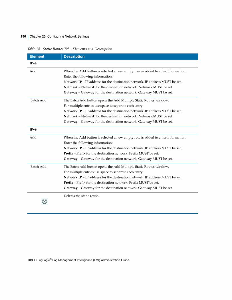
250 | Chapter 23 Configuring Network Settings
Table 14 Static Routes Tab - Elements and Description
Element Description
IPv4
Add When the Add button is selected a new empty row is added to enter information.
Enter the following information:
Network IP – IP address for the destination network. IP address MUST be set.
Netmask – Netmask for the destination network. Netmask MUST be set.
Gateway – Gateway for the destination network. Gateway MUST be set.
Batch Add The Batch Add button opens the Add Multiple Static Routes window.
For multiple entries use space to separate each entry.
Network IP – IP address for the destination network. IP address MUST be set.
Netmask – Netmask for the destination network. Netmask MUST be set.
Gateway – Gateway for the destination network. Gateway MUST be set.
IPv6
Add When the Add button is selected a new empty row is added to enter information.
Enter the following information:
Network IP – IP address for the destination network. IP address MUST be set.
Prefix – Prefix for the destination network. Prefix MUST be set.
Gateway – Gateway for the destination network. Gateway MUST be set.
Batch Add The Batch Add button opens the Add Multiple Static Routes window.
For multiple entries use space to separate each entry.
Network IP – IP address for the destination network. IP address MUST be set.
Prefix – Prefix for the destination netowrk. Prefix MUST be set.
Gateway – Gateway for the destination netowrk. Gateway MUST be set.
Deletes the static route.
TIBCO LogLogic® Log Management Intelligence (LMI) Administration Guide

Configuring your Network Settings | 251
Configuring your Network Settings
You can configure the Appliance on your network.
1. Access Administration > Network Settings from the navigation menu.
2. In the Hostname field, enter the hostname for your machine.
3. Select a default gateway for your machine. Your gateway can be either IPv4 or IPv6.
4. If you have DNS servers, type their IP addresses in the DNS Server fields. Enter Primary, Secondary, and Tertiary IP addresses in the respective fields.
5. Click the number of Static Routes link or the Static Routes tab to view a list of static routes, see Viewing Static Routes on page 254.
6. In Interface Pairing, choose the interface associated with the Appliance. Depending on the type of Appliance you have and the selection you make in the Default Gateway IP, the available Interfaces options will be displayed.
For your physical connections, see the <1_Emphasis>LogLogic Hardware Installation Guide.
Options include:
— pair eth0 and eth1 into bond0 (1U/2UR1 Appliances): Clear this checkbox to allow access to both eth0 and eth1. By default, the checkbox is selected, configuring the Appliance to use bond0. This lets the two physical interfaces, eth0 and eth1, become one logical interface. For example, to connect the Appliance to two separate networks, you must deselect the checkbox and configure eth0 and/or eth1, remembering to set your Gateway Interface as appropriate.
— pair eth1 and eth2 into bond0 (2U Appliances): Deselect this checkbox to allow access to both eth1 and eth2. By default, the checkbox is selected, configuring the Appliance to use bond0. This option allows up to five NICs.
— pair eth2 and eth3 into bond0: Deselect this checkbox to allow access to both eth2 and eth3. By default, the checkbox is selected, configuring the Appliance to use bond0. This lets the two physical interfaces, eth2 and eth3, become one logical interface. For example, to connect the Appliance to two
The eth0 port needs to be connected to the network because that is the only port configured on the Appliance by default at startup. The other ports will not work unless the eth0 port is connected to the network.
TIBCO LogLogic® Log Management Intelligence (LMI) Administration Guide

252 | Chapter 23 Configuring Network Settings
separate networks, you must deselect the checkbox and configure eth2 and/or eth3, remembering to set your Gateway Interface as appropriate.
— pair eth4 and eth5 into bond1: Deselect this checkbox to allow access to both eth4 and eth5. By default, the checkbox is selected, configuring the Appliance to use bond1. This option allows up to five NICs.
— pair eth4 and eth5 into bond2: Select this checkbox to allow access to both eth4 and eth5 as bond2. It makes the two physical interfaces, eth4 and eth5, become one logical interface. To connect the Appliance to two separate networks, you must deselect the checkbox and configure eth4 and/or eth5, remembering to set your Gateway Interface, IP address, and Netmask as appropriate?
— Enter the following in the Interfaces section:
— For IPv4:
Network IP Address—IP address for the interface. IP address MUST be set.
Netmask—Netmask for the IP address. Netmask MUST be set.
Speed—Select the connection speed from the drop-down menu.
— For IPv6:
Network IP Address—IP address for the interface. IP address MUST be set.
Prefix—Prefix for the IP address. Prefix MUST be set.
Speed—Select the connection speed from the drop-down menu.
7. Click Save to save your changes. If your changes require a reboot, click Reboot Now (from the top pane) to reboot the Appliance for the changes to take effect.
Configuring for a Multi-homed NetworkIf the appliance is configured to operate in a multi-homed network setting, the Linux kernel parameter of rp_filter must be changed from 1 to 0 for all the NIC interfaces. Static rules do not work if rp_filter is set to 1 or 2. There are multiple rp_filter settings and all of them should be modified. They are located at /proc/sys/net/ipv4/conf/*/rp_filter.
Once two Appliances are HA-paired, no network settings should be changed.
This operation could make the appliance vulnerable to DDoS attacks. See Red Hat documentation at https://access.redhat.com/solutions/53031.
TIBCO LogLogic® Log Management Intelligence (LMI) Administration Guide

Configuring your Network Settings | 253
To configure a multi-home network:
1. Find all network interfaces on the machine using the following command:$> ls /proc/sys/net/ipv4/conf/ | grep -v all | grep -v lo
2. With the list of network interfaces, edit the conf file /etc/sysctl.conf by appending the configuration into it, one line per interface:net.ipv4.conf.<interface_name>.rp_filter = 0
For example:net.ipv4.conf.default.rp_filter = 0
net.ipv4.conf.eth0.rp_filter = 0
net.ipv4.conf.eth1.rp_filter = 0
Reboot the machine for the settings to take effect.
If you already have static routes configured, you must configure the multi-home network and additionally change the values in /proc/sys/net/ipv4/conf/*/rp_filter. This is because though both have the same effect, changing the settings in /proc/sys/net/ipv4/conf/*/rp_filter, does not require rebooting the system.
TIBCO LogLogic® Log Management Intelligence (LMI) Administration Guide

254 | Chapter 23 Configuring Network Settings
Viewing Static Routes
You can view the existing static routes, add new routes and delete specified static routes using the Static Routes tab.
IPv4 Static Routes
Adding a Static Route
1. Click the Add button. A new empty row is added to enter information.
2. Enter the following information:
— Network IP—IP address for the destination network. IP address MUST be set.
— Netmask—Netmask for the destination network. Netmask MUST be set.
— Gateway—Gateway for the destination network. Gateway MUST be set.
3. Click Save. The new route is added in the Static Routes list.
Adding Multiple Static Routes
1. Click the Batch Add button. The Add Multiple Static Routes window appears.
2. Enter the following information. For multiple entries use space to separate each entry. You can copy and paste the multiple entries.
— Network IP—IP address for the destination network. IP address MUST be set.
— Netmask—Netmask for the destination network. Netmask MUST be set.
— Gateway—Gateway for the destination network. Gateway MUST be set.
3. Click Add. The new routes are added in the Static Routes list.
IPv6 Static Routes
Adding a Static Route
1. Click the Add button. A new empty row is added to enter information.
TIBCO LogLogic® Log Management Intelligence (LMI) Administration Guide

Viewing Static Routes | 255
2. Enter the following information:
— Network IP—IP address for the destination network. IP address MUST be set.
— Prefix—Prefix for the destination network. Prefix MUST be set.
— Gateway—Gateway for the destination network. Gateway MUST be set.
3. Click Save. The new route is added in the Static Routes list.
Adding Multiple Static Routes
1. Click the Batch Add button. The Add Multiple Static Routes window appears.
2. Enter the following information. For multiple entries use space to separate each entry. You can copy and paste the multiple entries.
— Network IP—IP address for the destination network. IP address MUST be set.
— Prefix—Prefix for the destination network. Prefix MUST be set.
— Gateway—Gateway for the destination network. Gateway MUST be set.
3. Click Add. The new routes are added in the Static Routes list.
Removing Static Routes1. Click the button from the Action column for each static route you want
to remove.
2. Click Yes in the confirmation window to delete the static route.
TIBCO LogLogic® Log Management Intelligence (LMI) Administration Guide

256 | Chapter 23 Configuring Network Settings
TIBCO LogLogic® Log Management Intelligence (LMI) Administration Guide

| 257
Chapter 24 Controlling Network Access to the Appliance
The Firewall Settings tab lets you restrict network access based on source IP address and destination port, similar to access lists used by routers or firewalls. For example, you can allow TCP port 443 access from a specific host or subnet.
Topics
• Using the Firewall Settings on page 258
• Adding an Input Rule on page 259
• Deleting an Input Rule on page 263
TIBCO LogLogic® Log Management Intelligence (LMI) Administration Guide
258 | Chapter 24 Controlling Network Access to the Appliance
Using the Firewall Settings
You can define rules for Source IP address or subnet, and destination TCP or UDP ports. Your input rules can allow and deny access based on the following criteria of the machine requesting authentication or access:
• IP address:
— All
— Single/Subnet Mask
• Protocol:
— TCP
— UDP
• Port:
For a list of ports please refer to LMI Ports on page 394.
You can change the Syslog UDP port number from 514, or specify additional port numbers. See General Settings on page 202.
• Action:
— Accept
— Deny
If non-default Syslog UDP Port is specified (using the Administration > System Settings > General tab) and the Enable IP Firewall checkbox is selected, then you must add an additional Input Rule for each non-default Syslog UDP port to allow this port to receive syslog messages. For instructions, see Adding an Input Rule on page 259.
TIBCO LogLogic® Log Management Intelligence (LMI) Administration Guide

Adding an Input Rule | 259
Adding an Input Rule
Use the Administration > Firewall Settings tab to add input rules and define your firewall settings. You can also use the command line interface menu item system iptables on|off command to turn off or on the IP tables used for Firewall Settings. For details, see Command Line Interface (CLI) on page 325.
New input rules are added to the bottom of the rule list. Input rules are processed in descending order. Therefore, if you add a rule that might be superseded by one of the higher rules in the list, you must first delete the higher rule for your new rule to be effective.
For example, a default input rule accepts all IP addresses with UDP port 514. If you add a rule denying access to a particular IP address (for example 180.22.21.5) using UDP and port 514, that rule is superseded by the higher default rule that accepts all input using UDP and port 514. To make your added rule effective, you must:
• Add a new rule denying 180.22.21.5 using UDP on port 514.
• Delete the default rule that accepts all IP addresses using UDP on port 514.
• To still accept all other IP addresses using UDP and port 514, add another new rule accepting all IP addresses using UDP on port 514.
Because this new “accept all” rule appears below the “deny 180.22.21.5” rule, both rules are executed. The Appliance accepts input from all IP addresses using UDP on port 514 except 180.22.21.5.
To add an Input Rule
1. Select Administration > Firewall Settings.
2. Select Enable IP Firewall to activate the Input Rule box.
Turning off Firewall Settings means any IP address can access the services on the Appliance.
TIBCO LogLogic® Log Management Intelligence (LMI) Administration Guide

260 | Chapter 24 Controlling Network Access to the Appliance
3. In the Input Rule box, define the rules:
a. Define an IP Address.
b. To accept all IP addresses with the Protocol and Port you define, select All.
c. Specify an IP address and/or subnet mask for the rule.
The IP address indicates which hosts are allowed to communicate with the appliance. The format for this field is IP-address/subnet-mask. For example:
For a 24-bit subnet mask: 192.168.2.0/24
For a 16-bit subnet mask: 192.168.0.0/16
For an 8-bit subnet mask: 192.0.0.0/8
For a 72 bit IPv6 subnet: fd0f:c4al:e456:0000:5200::/72
4. Select the Protocol (TCP or UDP) to associate with the port you specify.
5. Select a Port from the list of ports active on the Appliance.
For a list of ports please refer to LMI Ports on page 394.
TIBCO LogLogic® Log Management Intelligence (LMI) Administration Guide

Adding an Input Rule | 261
— HTTP: 80
— HTTP Collector: 4433
— HTTPS Remote Control: 4443
— HTTPS: 443
— Loglogic Tunnel: 11965 (this port is deprecated and may not be available for future releases)
— MCAGENT: 2508
— MCAGENT: 2098
— MCAGENT: 2099
— NTP: 123
— RealTime Viewer: 4514
— SSH: 22
— SNMP: 161
— SNMP-Trap: 162
— SYSLOG: 514
— Loglogic Receiver: 5514
— NetFlow: 2055
— NetFlow: 9555
— NetFlow: 9995
— ULDP: 5515
— ULDP: 5516
6. Select an Action radio button to indicate whether your Appliance accepts or denies a packet that meets the rule requirement. The default is Deny.
7. Click Add to add the rule to the Input Rule Table.
8. Click Apply to activate the rules.
The Input Rule Table, beneath the Input Rule box, lists the currently active rules.
Table 15 Input Rule Table
Column Description
IP Address IP address or subnet you typed for the Input Rule.
TIBCO LogLogic® Log Management Intelligence (LMI) Administration Guide

262 | Chapter 24 Controlling Network Access to the Appliance
Port Port you selected for the Input Rule.
Protocol Protocol you selected for the Input Rule.
Action Action to take if the packet meets your rule requirements.
Deletes the access rule from the list.
Table 15 Input Rule Table
Column Description
TIBCO LogLogic® Log Management Intelligence (LMI) Administration Guide

Deleting an Input Rule | 263
Deleting an Input Rule
Use the Administration > Firewall Settings tab to delete input rules and define your Firewall Settings. You can also use the command line interface system iptables on|off command to turn off the IP tables for Firewall Settings completely. For details see, Command Line Interface (CLI) on page 325.
1. Select Enable IP Firewall.
2. Click the icon for the rule to delete.
3. Click OK to exit the confirmation window.
4. You must click Apply to accept the changes.
The Appliance treats port 443 (HTTPS) differently; you cannot delete the last rule for port 443. This prevents you from losing browser access to your Appliance; at the same time letting you restrict access to port 443.
For a list of ports please refer to LMI Ports on page 394.
Table 16 Example of LogLogic Port Assignments
Description Protocol Port # Comments
Log Message Push
Syslog UDP 514 Used for incoming syslog data. You can change this port number from 514 in the System Settings > General tab Syslog UDP Port field. If you change this port number, you must add the other port number here.
Blue Coat/Netcache HTTP/ HTTPS
4433 Used for incoming HTTPS streams from log sources such as Blue Coat ProxySG and NetApp Netcache.
Check Point
lea_server LEA/TCP 18184 Used to transfer log messages.
cpmi_server TCP 18190 Default port. Used for rule listing and firewall/interface auto-discover. Note: Must match Check Point Manager Server.
TIBCO LogLogic® Log Management Intelligence (LMI) Administration Guide

264 | Chapter 24 Controlling Network Access to the Appliance
SIC TCP 18210 Used to establish connection with the Check Point Management Interface (CPMI). SIC - Secure Internal Communication
CMPI Forwarding UDP 5514 Used for collecting LogLogic streams from the Check Point Management Interface via the rtchpk utility.
GUI
Browser HTTP 80 Used for internal web browser access requests to the LogLogic Appliance. The requests are redirected to port 443 (HTTPS).
Browser HTTPS 443 Used for incoming HTTPS requests to the user interface and Web Services APIs. The requests are redirected from port 80 (HTTP).
Browser HTTP 8080 Browser redirects during upgrade.
Table 16 Example of LogLogic Port Assignments
Description Protocol Port # Comments
TIBCO LogLogic® Log Management Intelligence (LMI) Administration Guide

Deleting an Input Rule | 265
Real-Time Viewer TCP 4514 Used for Real-Time Viewer client connections. Uses Java applet; some versions of Java will not work. Java 1.8.0.x is recommended.
Note: If you are running java 1.8.0_x you will need to:
1. As administrator, update your file C:\Program Files (x86)\Java\jre1.8.0_x\lib\security\java.policy and grant the folowing permission to non-abbreviated IPv6 address:grant { permission java.net.SocketPermission "fd00:0:0:0:0:aaaa:a73:1a3d", "connect,resolve"; };
You can also add permissions to both abbreviated and non-abbreviated addresses:grant { permission java.net.SocketPermission "fd00:0:0:0:0:aaaa:a73:1a3d", "connect,resolve"; };
grant { permission java.net.SocketPermission "fd00::aaaa:a73:1a3d", "connect,resolve"; };
The IP address should be replaced with the IP address of your appliance.
2. In Control Panel > java > Security add the following to the exception list:https://[fd00::aaaa:a73:1a3d]:443, where "fd00::aaaa:a73:1a3d” is your appliance IP
https://[fd00:0:0:0:0:aaaa:a73:1a3d]:443, where "fd00:0:0:0:0:aaaa:a73:1a3d” id the non-abbreviated version for your appliance IP
Note: Appliance IP Address can be either IPv4 or IPv6. Both are supported.
Miscellaneous
CLI Access SSH 22 Used for SSH client access. Configured on/off.
NTP NTP 123 Used by the Network Time Protocol Daemon (NTPD).
Browser HTTPS 443 Used for SSL two-way handshake.
Failover
Table 16 Example of LogLogic Port Assignments
Description Protocol Port # Comments
TIBCO LogLogic® Log Management Intelligence (LMI) Administration Guide

266 | Chapter 24 Controlling Network Access to the Appliance
High Availability Failover
Rsync 4400 Used by the replication sync failover service.
High Availability Failover
MySQL 3306 Used by the MySQL failover service.
Outbound Traffic
LogLogic TCP TCP 5514 Used for collecting LogLogic streams from the Check Point Management Interface via the rtchpk utility.
LogLogic TCP TCP 4443 Used by Management Station to send requests from the Management Station to a remote Appliance.
LogLogic TCP TCP 4443 Used for sending updates from a Remote Appliance to the Management Station.
[Also removed from Firewall Settings > Port list and Table 30]
Syslog Alert UDP 514 Used for incoming syslog data. You can change this port number from 514 in the System Settings > General tab Syslog UDP Port field. If you change this port number, you must add the other port number here.
SNMP Alerts UDP 161 Used for incoming SNMP client requests.
SNMP Notification UDP 162 Used for incoming and out going SNMP trap messages. (Internal LX/ST Alerts and log collection)
Table 16 Example of LogLogic Port Assignments
Description Protocol Port # Comments
TIBCO LogLogic® Log Management Intelligence (LMI) Administration Guide

| 267
Chapter 25 Managing SSL Certificates
There are three ways to generate and activate SSL certificates for a LogLogic Appliance:
• LogLogic signed certificate—the Appliance creates and activates its own certificate and private key
• Certificate Authority (CA) certificate—a CA is used to provide the root and signed (reply) certificates; the Appliance private key is used
• Other certificate—the Appliance uses certificates and a private key that you generate and provide from a source other than the first two options
Topics
• LogLogic Signed Certificate on page 268
• Signing the Certificate Using a CA on page 269
• Importing Certificates and a Private Key on page 272
• Trusted Certificate on page 273
TIBCO LogLogic® Log Management Intelligence (LMI) Administration Guide

268 | Chapter 25 Managing SSL Certificates
LogLogic Signed Certificate
Use the LogLogic Signed Certificate tab to create and activate a LogLogic signed certificate for your Appliance IP.
To Accept and Activate your LogLogic Signed Certificate:
1. Click Administration > SSL Certificate.
2. The LogLogic Signed Certificate tab opens.
3. In the Common Name text field, enter the DNS name (recommended) or IP address of the LogLogic Appliance.
4. In the Organizational Unit text field, enter the name of your department.
5. In the Organization text field, enter the name of your company.
6. In the City text field, enter the name of your city.
7. In the State Name text field, enter the name of your state.
8. In the Country drop-down menu, select the abbreviation of your country.
9. In the Validity Period text field, enter the number of days for which the certificate remains valid.
10. Click Activate.
The Appliance creates its own certificate and private key using the LogLogic root CA to sign the certificate, and then activates the new certificate and private key. Tomcat automatically restarts to apply the changes
Completing this procedure before changing the Certificate Signing Request changes the private key. You must maintain consistency between your keys.
TIBCO LogLogic® Log Management Intelligence (LMI) Administration Guide
Signing the Certificate Using a CA | 269
Signing the Certificate Using a CA
Use the Certificate Signing tab to generate a signing request for the current certificate used by the Appliance. After the CA signs the request, use this tab to import the CA root certificate and the signed certificate.
You must first complete the LogLogic Signed Certificate tab. This procedure uses information from that tab, as well as the Appliance private key it activates.
If your organization's PKI policies dictate the use of one or more intermediate certificate authorities, an additional step is required to ensure that LMI can properly verify the entire certificate trust chain.
The simplest configuration involves the LMI certificate and a root certificate. In such a scenario, the root certificate is not just the root CA, but also the signing CA. This distinction is important when determining the sequence in which to paste the certificates.
• When using multiple CA certificates, consider the Root Certificate text box as a field that is used for the Issuing Certificate, and then all other CA certificates will be added in the same box (see step 5b).
• In situations involving a single CA certificate that serves as both the root and issuing CA, the intermediate CA is the signing CA and the root is still the root CA (see step 5a). There can be any number of intermediate CAs. The exact situation depends on your organization's policies.
1. Click Administration > SSL Certificate > Certificate Signing.
2. Click Generate.
Some certificate authority software do not provide all the necessary files when returning your signed certificate, and some do not require any intermediate certificates. However, LogLogic LMI does require them if they are used in the certificate signing process. Therefore, if you do not know how many CA certificates to expect to be given when your signed host certificate is returned to you, then please verify with your organizationa's PKI administrators whether your organization uses multiple CA certificates. There is no limit to the quantity of intermediate certificates that LMI can use.
By default the GUI generates CSRs with keys that are 2048 bit in size.
TIBCO LogLogic® Log Management Intelligence (LMI) Administration Guide

270 | Chapter 25 Managing SSL Certificates
A certificate signing request (CSR) from LogLogic is generated based on the information in the LogLogic Signed Certificate tab. The certreq.csr dialog appears.
3. Open the .csr file.
4. Copy the text from the .csr file to the website of your trusted CA. The CA returns a root and reply certificate.
5. Perform any one of the following:
a. If your organization uses a single CA certificate that serves as both the root and issuing CA, paste the text from the root certificate of the CA into the Root Certificate text box. Then proceed to step 6.
b. If your organization uses multiple CA certificates, perform the following steps:
— Paste in the certificate that was given to you by your PKI system that was used to sign the LMI appliance's certificate.
— Paste in the contents of each CA certificate in reverse order of the certificate chain, so that the top root CA certificate is pasted as the last certificate.
For example, if you have the following certificates with Common Names (CN= values) of toprootCA, interCA, signingCA, and myLMI, and with the certificates in that sequence within the trust chain, then they must be pasted into the Root Certificate text box using the following bottom up order:
1. signingCA.cer
2. interCA.cer
3. toprootCA.cer
The myLMI certificate will be pasted into the separate Reply Certificate text box during step 6.
If you are unsure which sequence the CA certificates exist in the chain, contact your organization's PKI administrator ,or follow the certificate chain by looking at the Issued By and Issued To fields for each certificate. The first certificate pasted into the Root Certificate text box must be the one
Generating a root and reply certificate from the CA might take time.
If the order is random, backwards, or incorrect in some way, the certificates will not work correctly after the LMI web server is restarted.
TIBCO LogLogic® Log Management Intelligence (LMI) Administration Guide

Signing the Certificate Using a CA | 271
that signed the LMI appliance's certificate. The last certificate that is pasted in the Root Certificate text box must be the top-level root CA certificate.
6. Paste the text from the CA-generated certificate into the Reply Certificate text box.
7. Click Import to import the certificate.
Tomcat automatically restarts to apply the changes.
• Do not separate the certificate contents with blank lines.
• Make sure that the contents of each certificate start on a new line.
TIBCO LogLogic® Log Management Intelligence (LMI) Administration Guide

272 | Chapter 25 Managing SSL Certificates
Importing Certificates and a Private Key
Use the Certificate Import tab to activate your own certificates and a private key that you generate from another source beside the appliance itself.
1. Click Administration > SSL Certificate > Certificate Import.
2. Paste the root certificate into the Root Certificate box.
3. Paste the generated private key into the Private Key box.
4. Paste the certificate generated for this Appliance IP address into the Certificate box.
5. Click Activate.
Tomcat automatically restarts to apply the changes.
Completing this procedure before changing your Certificate Signing Request, changes your private key. You must maintain consistency between your keys.
TIBCO LogLogic® Log Management Intelligence (LMI) Administration Guide

Trusted Certificate | 273
Trusted Certificate
Use the Trusted Certificate tab to create a trusted relationship with other Appliances you trust.
To create a trusted relationship with other Appliances you trust
1. On the Management Station, click Administration > SSL Certificate > Trusted Certificate. Using your browser’s copy/paste functionality, copy the Current Certificate.
2. On the Remote Appliance click Administration > SSL Certificate > Trusted Certificate. Paste the Management Station's Current Certificate into the Import Trusted Certificate text box.
3. Click the Import button.
This action imports the new trusted certificate from the text box and installs it on the Remote Appliance, thereby establishing a trusted relationship with the originator of the imported certificate (Management Station).
The Remote Appliance web server will automatically restart, but data collection on the Remote Appliance is not affected.
TIBCO LogLogic® Log Management Intelligence (LMI) Administration Guide

274 | Chapter 25 Managing SSL Certificates
TIBCO LogLogic® Log Management Intelligence (LMI) Administration Guide

| 275
Chapter 26 Failover
The LogLogic failover feature allows high availability (HA) of an LX, ST, MX or EVA Appliance by providing:
• Real-time replication of logs
• A fast and reliable failover mechanism
Topics
• Failover Architecture on page 276
• Failover Recommendations on page 281
• Installation and Configuration on page 284
• Failover Management on page 292
• Node Failure and Recovery on page 295
TIBCO LogLogic® Log Management Intelligence (LMI) Administration Guide

276 | Chapter 26 Failover
Failover Architecture
You can configure LogLogic Appliances in a one-to-one HA pair failover configuration. There is a single active Appliance with a single standby Appliance. The standby Appliance continually stays in sync with the active Appliance and automatically takes over for the active Appliance if a problem arises.
Each Appliance has its own private IP address. The HA pair itself has a public IP address, which serves as the single entry point for the HA pair. All external systems point to the public IP address so data goes to the active Appliance in the HA pair regardless of which Appliance it is at a given time.
LogLogic failover is built on three software layers that together ensure failover membership, database replication, and recurring node resynchronization.
Public/Private IP AddressesLogLogic failover is based on an active/standby architecture and provides a single system image composed of two Appliances of the same type. The two Appliances can be treated as a virtual Appliance accessed using a single public IP address.
Each of the two Appliances is configured using a private IP address. To configure the private IP address, use the UI System Settings > Network tab or the CLI set IP command.
The public IP address is the single entry point of the failover pair. All log sources for logs collected by the failover Appliances must use the public IP address as their target IP.
The public IP address is specified during failover configuration. At any instant, only one Appliance owns the public IP address and acts as a primary node for collecting and processing logs. The other node is the exact replica, in real time, of the primary node and acts as a standby. In the event of a primary node failure, the public IP address defers to the standby to guarantee availability and minimal loss of logs.
It is strongly recommended that in an HA pair, the two Appliances must have:
• the same model
• the same LMI and LSP versions, (the hotfix versions need not match)
TIBCO LogLogic® Log Management Intelligence (LMI) Administration Guide

Failover Architecture | 277
Figure 17 Example: Failover Solution for an LX Appliance
Failover and External StorageExternal storage for ST Appliances, such as NAS storage, is not replicated as part of the failover configuration.
When configuring a NAS device used by an ST Appliance in an HA pair, add the private IP addresses of both ST Appliances and the public IP address to the NAS device’s accepted IP address list.
When an ST Appliance fails over, its NAS storage is automatically switched over to the standby Appliance as it becomes active. For example:
1. Appliance 1 is the active ST Appliance, Appliance 2 is the standby ST Appliance, NAS storage is in use by Appliance 1.
2. Appliance 1 fails, Appliance 2 becomes the new active Appliance.
3. Appliance 2 immediately starts using the NAS storage directly, just as Appliance 1 had before.
TIBCO LogLogic® Log Management Intelligence (LMI) Administration Guide

278 | Chapter 26 Failover
Failover and Backup/RestoreBackup is performed on an HA pair similarly to how it is run for a single Appliance. Configure the backup to use the public IP address.
Restoring from a backup to an HA pair involves disabling and re-enabling failover. For more information, see Backup and Restore in an HA Pair on page 152.
Failover Software LayersThere are three software layers in the LogLogic failover implementation:
• Failover Membership on page 278
• Real-Time Replication on page 279
• Node Resynchronization on page 279
Each layer represents a building block responsible for a specific functionality.
Failover Membership
The failover membership layer monitors and detects a node failure in real time. It provides a fast and reliable election mechanism to dynamically failover the public IP address from the node that just failed to an active partner node.
The Appliances in the failover configuration are organized in a ring architecture, with two members, or partners, in the ring. Each node monitors its successor through a TCP connection. A small network packet is sent at regular intervals to the successor node.
Failure to receive consecutive heartbeat packets triggers a recovery operation. A recovery operation consists of moving the public IP address to another node. After a node failure detection, a new active node is elected and it assumes the public IP address. In a normal situation, the total time for a failure recovery is 3 seconds. The public IP address is added to a network interface chosen by the user when configuring the HA feature. The HA feature also uses a network interface to monitor a partner node and to carry data replication traffic. The interface is also chosen by the user among those that already have an IP address assigned (Note that the user is prompted to chose only if there is more than one choice). In order to properly monitor that the public IP address is accessible, both interfaces need to be the same.
TIBCO LogLogic® Log Management Intelligence (LMI) Administration Guide

Failover Architecture | 279
Real-Time Replication
Most Appliance data is stored in MySQL database tables. The real-time replication of the data between the active and standby nodes is done using MySQL replication.
Each node is configured to replicate its databases as defined by the failover membership. The software layer responsible for the real time replication of the data dynamically configures MySQL according to the current state of the failover membership and continuously monitors the progress of the replication recovering any non-fatal error.
MySQL replication provides real-time latency while being very reliable. An SQL replication is usually done in less than two seconds and the protocol correctly handles temporary network disconnection. The volatile data stored in memory and the configuration files stored on disk of the current active Appliance are replicated on the standby node every minute.
Node Resynchronization
An operation is periodically started in the background to check and resynchronize the archived data. The time needed to resynchronize both nodes depends on the available network bandwidth and the data size difference. It can be a time-consuming operation, from 5 minutes up to multiple days in the case of an Appliance replacement.
An Appliance has two types of data:
• Archived data (read-only)
• Active data (currently being modified)
Archiving is based on a threshold of disk usage. Node resynchronization is a background mechanism triggered by a failover membership event or activated periodically to resynchronize the standby with the active node, and guarantees that both Appliances have exactly the same data in time.
The implementation is based on an open source utility that provides fast incremental file transfer. A wrapper software on top of the utility provides an online checkpoint mechanism of database tables.
When a node that is configured to be part of an HA pair connects with its partner for the first time, an automatic data migration takes place. This operation makes one node a copy of the other. The node that keeps its original content is known as the Source node. The node that loses its original content is known as the Destination Node. The destination node is designated by the user when configuring the HA feature on each node. This operation resumes after
TIBCO LogLogic® Log Management Intelligence (LMI) Administration Guide

280 | Chapter 26 Failover
disconnections or shutdown of any of the pair members, until completed. Only once this is completed is the pair able to provide the fail-over feature. Until then the Source node assumes the public IP and acts as the Active node. The Destination acts as the standby node but is not allowed to become Active.
After the data migration is complete, and as long as both nodes remain connected, the standby node contains the same data as the active node with at most one minute of latency (LX) or less than 3 seconds of latency (ST). If a node is temporarily disabled and later rejoins the cluster, it becomes the standby node and starts an operation to resynchronize with the active node. During this initial data migration that occurs when a node joins the cluster, the following data is removed:
• Data collected on the standby node before it rejoins the cluster
• Data that does not already exist on the master
TIBCO LogLogic® Log Management Intelligence (LMI) Administration Guide

Failover Recommendations | 281
Failover Recommendations
LogLogic provides several best practices for its failover feature, related to maximizing HA pair performance and identifying certain limitations of the failover offering.
Failover PerformanceFailover performance metrics include failover time and maximum message rates.
• The failover time is 3 seconds in a normal situation. The failure detection time is 1 second, and the error recovery period is 2 seconds. Heartbeat monitoring is done over the TCP/IP protocol using a heartbeat packet of 64 bytes and a latency of 100ms.
• The failover configuration supports the same maximum message rate as a single LogLogic Appliance with the same limitations.
Failover LimitationsThere are a few limitations in the LogLogic failover feature:
• The Real-Time report for Active VPN Connections (under Connectivity) is not available on the standby Appliance. It uses a specific shared memory structure that cannot be replicated on the standby Appliance.
• The public IP address assigned to the failover function is an alias of the main network interface of the Appliance. This is required as part of the mechanism used to update the Address Resolution Protocol (ARP) tables in case failover occurs. Since some routers fail to release the cache of IP and hardware addresses stored in their ARP tables (or store the cache for as long as 10 minutes), the LogLogic Appliance sends out an ARP-release packet once per minute. This causes the router to broadcast a discovery request to find the IP address and hardware address of the devices connected to it. When failover occurs, (or when we set up a High Availability (HA) pair), the router ARP tables will be updated automatically.
• The virtual public IP address cannot be used for remote authentication (RADIUS, TACACS). Record the private IP addresses of both Appliances in the remote server.
Make configuration changes only to the active Appliance, and not to the standby Appliance. To avoid mistakes, always use the cluster’s Virtual IP address to interact with the configuration UI.
TIBCO LogLogic® Log Management Intelligence (LMI) Administration Guide

282 | Chapter 26 Failover
• While setting up an HA pair, various configuration files are automatically synced between the master and slave node. If any configuration file is updated after the setup is complete, you must:
— manually sync the changes to the slave node by running the command /loglogic/bin/loadsettings on the master node.
— restart the corresponding engine on both nodes, in the following sequence:
a. stop the engine on the slave and then on the master
b. start the engine on the master and then on the slave
This applies to the following files, defined in /loglogic/conf/rsync_conf_files:— /root/.ssh/id_dsa
— /root/.ssh/id_dsa.pub
— /etc/ssh/ssh_host_rsa_key.pub
— /etc/ssh/ssh_host_rsa_key
— /etc/issue
— /etc/localtime
— /etc/resolv.conf
— /loglogic/conf/ll_tunnel.conf
— /loglogic/conf/ll_tunnel.id
— /loglogic/conf/ll_tunnel.key
— /loglogic/conf/ll_tunnel_c.conf
— /loglogic/conf/dbtablerules/tablerule40.txt
— /loglogic/conf/preloadFmtConf.txt
— /loglogic/conf/activeFmtConf.txt
— /loglogic/conf/arc_limit
— /loglogic/conf/archive_config
— /loglogic/conf/archive.sql
— /loglogic/conf/archiver.conf
— /loglogic/conf/agg.conf
— /loglogic/conf/snmpd.conf
— /loglogic/conf/mtask.conf
— /loglogic/tomcat/conf/truststore
— /loglogic/data/dfas/*
— /loglogic/data/lea_cert*.p12
TIBCO LogLogic® Log Management Intelligence (LMI) Administration Guide

Failover Recommendations | 283
— /loglogic/status/database_backup_status.txt
— /loglogic/status/tcp_parser.bfq.cursor
— /loglogic/tmp/lastbackup
— /loglogic/conf/centera.pea
— /loglogic/conf/ffrf/*
• The SSL certificates for HTTPS are not replicated from master to slave when using HA.
• When logging into the Web UI for the first time after HA failover, you may see a "Security violation" error when CSRF is enabled. If you see this error, relogin using the Public IP with a new browser session.
Once two appliances are paired in HA, no network settings can be changed.
In failover configuration, the administrator needs to modify archive mounting points on both master and standby Appliances.
1. Configure mounting points for SAN or NAS through public IP.
2. On the master (Appliance A), modify the mounting points from Admin > System Settings > Archive Mapping page.
3. When the prompt asks to reboot the system click OK.
The former standby (Appliance B) will become the new master once the former master starts the reboot process. The administrator needs to modify the mounting points from the Admin > System Settings > Archive Mapping page for the new master (Appliance B) again, before the former master (Appliance A) finishes the rebooting process.
TIBCO LogLogic® Log Management Intelligence (LMI) Administration Guide

284 | Chapter 26 Failover
Installation and Configuration
Installing and configuring failover includes the following:
• Hardware Installation on page 284
• Software Setup (New HA Pair) on page 285
• Software Setup (Replacing an HA Pair) on page 289
Data migration is automatically performed when you set failover on an Appliance. Data migration gets the standby Appliance data in sync with the active Appliance before setting up the failover relationship. This migration ensures that useful data on the active Appliance is not accidentally overwritten during failover by data from the standby Appliance.
For more information on how data migration works, see Migrating Data Between Appliances on page 299. The procedures in that chapter are performed automatically during failover configuration.
Hardware InstallationThe following diagram shows optimal high availability hardware setup for the failover configuration. The eth0 NIC of each Appliance is plugged in the same switch, and the eth1 NIC on a different switch. The Appliances are configured to use the fault-tolerant network interface bond0.
Advanced features are not supported in high availability (HA).
TIBCO LogLogic® Log Management Intelligence (LMI) Administration Guide

Installation and Configuration | 285
Figure 18 Failover Hardware Setup
Other configurations also work. Each Appliance can be connected to the network using the same or a different switch, using bond0 or not, and either or both NICs (eth0 and eth1). Network configuration that uses eth0 and eth1 independently is supported. As long as the failover membership can be established between the two nodes to guarantee the real-time replication of data, the failover works.
When choosing the IP addresses:
• Each Appliance must be able to access the other Appliance using its private IP address.
• Each Appliance must be able to own the public IP address.
• The last digit of each IP address must be different.
Software Setup (New HA Pair)Both Appliances need to be installed with compatible versions of the LogLogic software. The failover membership cannot be established if there is a mismatch in software versions between the two nodes. The both softwares need to have the same:
• HA protocol version
• Log storage format version
• LSP installed version
• Database schema version
TIBCO LogLogic® Log Management Intelligence (LMI) Administration Guide

286 | Chapter 26 Failover
Setting up Failover
1. Set the NTP server on both Appliances that will be in the HA pair.
a. Log in to the UI web server using the private IP address of the Appliance.
b. Change the administration password, if required.
c. Configure the Appliance time via the Administration > System Settings >Time tab.
d. It is good practice to use the network time protocol (NTP) for failover configurations. Setting the NTP server on one Appliance in the HA pair automatically sets it on both Appliances and reboots them both accordingly.
It is essential to set the NTP server time correctly during Appliance installation.
2. Through the CLI via a serial console, log in to the Appliance that will be the active node in the HA pair.
3. Configure the Appliance with a private IP address:
set ip <IP address> <netmask> <gateway> [ifdev] [defaultgw]
For example, using 10.1.1.71 as the private IP address and 10.1.1.1 as the gateway: > set ip 10.1.1.71 255.255.255.0 10.1.1.1 bond0New interface settings:ip 10.1.1.71 255.255.255.0 10.1.1.1 CHANGES HAVE NOT BEEN SAVED!> save>
Use a serial console instead of an SSH connection. Network configuration changes can disconnect an SSH connection during this procedure. In all circumstances, a serial connection is maintained.
If you configure more than one interface in the set ip command, make sure the subnets do not overlap.
TIBCO LogLogic® Log Management Intelligence (LMI) Administration Guide

Installation and Configuration | 287
4. Configure failover by providing the public IP address of the failover and the private IP address of the second Appliance with the set failover configure command.
For example, using 10.1.1.177 as the public IP address and 10.1.1.72 as the private IP address of the other Appliance:
In case of IPv6, use :: as the value of <broadcast>.> set failover configureEnter the public Ip for the HA partner pairin the form <ip> <netmask> <broadcast> <ifdev>: 10.1.1.177 255.255.255.0 10.1.1.255 bond0Should this appliance be the destination of automatic migration: NEnter the Ip address of the peer appliancein the form <ip>: 10.1.1.72
CHANGES HAVE NOT BEEN SAVED!>
5. Save the changes to apply the new configuration:> saveWriting changes to disk...Generating new SSL certificate...Generating RSA private key, 1024 bit long modulus
...STOPPING MASTER TASK..............................(ok)[writing new cluster configuration]STARTING MASTER TASK...(ok)done.>
6. Repeat this procedure on the standby Appliance.
7. Confirm that the NTP server settings, and the actual observed time, are identical on both Appliances in the HA pair.
Make sure that the subnet in the set failover configure command is the same as the one configured for the same interface in the set ip command.
Also, if you specify an interface it must be an existing interface configured with a different IP address in the set ip command.
On the standby Appliance, in Step 4 indicate Y for the appliance to be the destination of automatic migration.
If both Appliances are configured as destinations, or if neither Appliance is, the HA pair does not form. Both Appliances report that they are out of cluster.
TIBCO LogLogic® Log Management Intelligence (LMI) Administration Guide

288 | Chapter 26 Failover
8. It is essential to set the NTP server time correctly during Appliance installation.
The failover is now set up and both Appliances are synchronizing their data.
You can log into the active node using the public IP address of the failover to finish Appliance configuration. During normal operations, it is good practice to use the public IP address of the failover for configuration changes and the private IP address of the standby to run reports as this leaves the active node fully available for collecting and processing logs. The standby is always the same and only changes in case of failover. The Administration > System Settings > Network tab always shows the private IP address of an Appliance.
Setting up Failover with a different interface
1. The interface configured by “set ip” is used to send replication traffic and heartbeats to another Appliance and to send heartbeats to the other Appliance as well.
2. If more than one such interface is to be configured, the user will be asked to select which one is going to be used for HA replication and heartbeat.
3. The interface configured by “set failover” will be used to assign the public IP address and will therefore receive logs. The LogLogic software requires that it be one of the interfaces configured by “set ip”.
4. It is possible to select an interface other than any selected in Steps 1 and 2. The “downside” of this configuration is the interface may still send heartbeats while logs are not received. The “upside” is that replication traffic will not interfere with the logs, and may use a back-to-back crossover cable, avoiding dependency on a switch.
5. “Ip address of the peer appliance” is the destination of the replication traffic and of the heartbeats. It must therefore match the IP address assigned to the interface configured ON THE OTHER NODE during Steps 1 and 2.
Software Setup (Replacing a Single Node)Replacing the active or standby node in an HA pair can be either a planned exercise for replacing hardware, or an unplanned replacement due to a failover situation caused by a node failure.
Remember that bond interfaces encapsulate actual network interfaces. Therefore, if a bond interface is configured, then the encapsulted network interfaces may not be configured separately. For that reason, it is not advisable to configure bond interfaces and non-bond interfaces on the same Appliance.
TIBCO LogLogic® Log Management Intelligence (LMI) Administration Guide

Installation and Configuration | 289
In either situation, see Failure and Recovery of the Active or Standby Node on page 295.
Software Setup (Replacing an HA Pair)This procedure is for the replacement of an existing HA pair with a new HA pair without interrupting log collection.
All four Appliances must be running the exact same version of the LogLogic software. The failover membership cannot be established if there is a mismatch in software releases between the nodes. If you must upgrade an Appliance, see the TIBCO LogLogic® Log Source Packages Log Source Configuration Guide for the release to which you are upgrading.
The last digit of the Appliances’ IP addresses cannot be the same, because the final digit is used as the failover node ID.
In this procedure:
• Appliance A - current active node (10.1.1.71)
• Appliance B - current standby node (10.1.1.72)
• Appliance C - new active node (new 10.1.1.72)
• Appliance D - new standby node (new 10.1.1.71)
1. Ensure that Appliances C and D use the same NTP server as Appliances A and B.
a. Log in to the UI web server using the private IP address of the Appliance.
b. Configure the Appliance time via the Administration > System Settings >Time tab.
2. Shut down the current standby node, Appliance B, without changing the failover configuration on the current active node, Appliance A.
3. Through the CLI via a serial console, log in to Appliance C.
4. Configure Appliance C with the private IP address that Appliance B was using:
set ip private-ip-address netmask gateway [ifdev] [defaultgw]
For example, using 10.1.1.72 as the private IP address and 10.1.1.1 as the gateway:
Changing NTP settings on the active Appliance in an HA pair reboots both Appliances in the pair.
TIBCO LogLogic® Log Management Intelligence (LMI) Administration Guide
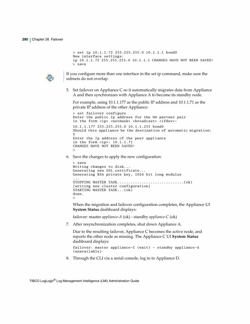
290 | Chapter 26 Failover
> set ip 10.1.1.72 255.255.255.0 10.1.1.1 bond0New interface settings:ip 10.1.1.72 255.255.255.0 10.1.1.1 CHANGES HAVE NOT BEEN SAVED!> save
5. Set failover on Appliance C so it automatically migrates data from Appliance A and then synchronizes with Appliance A to become its standby node.
For example, using 10.1.1.177 as the public IP address and 10.1.1.71 as the private IP address of the other Appliance:> set failover configureEnter the public Ip address for the HA partner pairin the form <ip> <netmask> <broadcast> <ifdev>:
10.1.1.177 255.255.255.0 10.1.1.255 bond0Should this appliance be the destination of automatic migration: YEnter the Ip address of the peer appliancein the form <ip>: 10.1.1.71CHANGES HAVE NOT BEEN SAVED!>
6. Save the changes to apply the new configuration:> saveWriting changes to disk...Generating new SSL certificate...Generating RSA private key, 1024 bit long modulus...STOPPING MASTER TASK..............................(ok)[writing new cluster configuration]STARTING MASTER TASK...(ok)done.>
When the migration and failover configuration completes, the Appliance UI System Status dashboard displays:
failover: master appliance-A (ok) - standby appliance-C (ok)
7. After resynchronization completes, shut down Appliance A.
Due to the resulting failover, Appliance C becomes the active node, and reports the other node as missing. The Appliance C UI System Status dashboard displays:failover: master appliance-C (wait) - standby appliance-A (unavailable)
8. Through the CLI via a serial console, log in to Appliance D.
If you configure more than one interface in the set ip command, make sure the subnets do not overlap.
TIBCO LogLogic® Log Management Intelligence (LMI) Administration Guide

Installation and Configuration | 291
9. Configure Appliance D with the private IP address that Appliance A was using.
set ip private-ip-address netmask gateway [ifdev] [defaultgw]> set ip 10.1.1.71 255.255.255.0 10.1.1.1 bond0
New interface settings:
ip 10.1.1.71 255.255.255.0 10.1.1.1 CHANGES HAVE NOT BEEN SAVED!
10. Set failover on Appliance D so it automatically migrates data from Appliance C and then synchronizes with Appliance C to become its standby node.
For example, using 10.1.1.177 as the public IP address and 10.1.1.72 as the IP address of the peer Appliance:> set failover configureEnter the public Ip address for the HA partner pairin the form <ip> <netmask> <broadcast> <ifdev>:
10.1.1.177 255.255.255.0 10.1.1.255 bond0Should this appliance be the destination of automatic migration: YEnter the Ip address of the peer appliancein the form <ip> <netmask> <broadcast> <ifdev>: 10.1.1.72CHANGES HAVE NOT BEEN SAVED!>
11. Save the changes to apply the new configuration:> saveWriting changes to disk...Generating new SSL certificate...Generating RSA private key, 1024 bit long modulus...STOPPING MASTER TASK..............................(ok)[writing new cluster configuration]STARTING MASTER TASK...(ok)done.>
When the migration and failover configuration completes, the Appliance UI System Status dashboard displays:failover: master appliance-C (ok) - standby appliance-D (ok)
The failover is now set up and both new Appliances are synchronizing their data.
TIBCO LogLogic® Log Management Intelligence (LMI) Administration Guide

292 | Chapter 26 Failover
Failover Management
To monitor the current state of the failover setup, the Appliance provides information via several mechanisms:
• Alerts can be configured to send email during an error condition; for example, if failover occurs or a resynchronization error occurs.
• Detail events are logged internally to record the history of the failover state.
• Configuration of Alert monitoring of failover events (and others) is performed on the Alerts > Manage Alert Rules page. All pre-configured System Alerts are visible on this page.
Figure 19 Manage Alert Rules
• Click on the Alert Name to open the General tab, where you may edit the preconfigured Alert settings, and select other System Alerts.
• The Alert Receivers tab appears next to the Devices tab (or General tab, for a System Alert) when you create a new alert. You must specify an alert receiver for which the alert can be triggered in this tab.
The Appliance can generate an alert to be sent to an alert receiver when the alert rule is triggered. The Alert Receivers tab lists all the available alert receivers configured for the Appliance.
• Email recipients for System Alerts appear on the Email Recipients tab. All admin users are automatically selected to receive System Alerts. Other users can be configured on the Management > Users > Privileges tab.
TIBCO LogLogic® Log Management Intelligence (LMI) Administration Guide

Failover Management | 293
• To search for all operational events on the LogLogic Appliance, select Reports > Operational > System Events and click the Create Report button. Follow the onscreen prompts to generate the report.
• The RAS Warning page of the UI displays the status of the failover in real time.
Failover Warnings
Failover Appliance Unavailable
When the failover membership cannot be formed, a message such as the one shown below displays. The warning message will describe the nature of the failover issue.
Figure 20 Failover Warning Message
Failover in Degraded Mode
When the failover Appliances appear to get out of sync, a message displays.
In this situation, a permanent failure of one of the Appliances can result in data loss. If both nodes are mostly in sync, this resynchronization operation is relatively fast. However, if the data size difference is large, the operation time depends mainly on the network, CPU, and I/O bandwidth available. There are multiple phases involved in resynchronizing the failover, each with their own status and percentage to completion.
TIBCO LogLogic® Log Management Intelligence (LMI) Administration Guide

294 | Chapter 26 Failover
Figure 21 Failover Degraded Mode Warning Message
HA Software UpgradePlease refer to the section: “Upgrading in a High Availability Environment” in the TIBCO LogLogic® Log Management Intelligence (LMI) Configuration and Upgrade Guide.
TIBCO LogLogic® Log Management Intelligence (LMI) Administration Guide

Node Failure and Recovery | 295
Node Failure and Recovery
Three types of failure can occur with failover:
• Node failure
• Active/Standby node failure
• Double failure
Node Failure Loss of network connectivity is considered a node failure; that is, the miss of a heartbeat and failure to establish a TCP connection.
This can occur due to a hardware failure (the node is down), a network connection failure, or a network partitioning or a software error escalation. Every process running on the Appliance is monitored and a repeated software error condition can trigger an escalation that reboots the Appliance, hence triggering a node failure in the context of the failover.
Ethernet Disconnection
If the ethernet cable is unplugged from a primary Appliance in an HA pair, a failover triggers. HA pair (cluster) memberships fail, and eventually the primary Appliance enters failsafe mode. Plugging in the ethernet cable stops the failures, but the Appliance remains in failsafe mode.
To get an Appliance out of failsafe mode:
> mtask -s cluster_membership stop
> mtask -s cluster_membership start
Failure and Recovery of the Active or Standby Node If the current active node fails, the standby node takes over and becomes the active node. When a node joins the failover it becomes the standby and a node resynchronization operation starts. The standby resynchronizes both the missing and existing data from the active node (including the currently modified data set) and the active node resynchronizes the missing data from the standby node.
The following is a sample Failover configuration using the following parameters:
• Active Appliance: 10.20.0.10
• Standby1: 10.20.0.11 (old, to be replaced by Standby2)
TIBCO LogLogic® Log Management Intelligence (LMI) Administration Guide
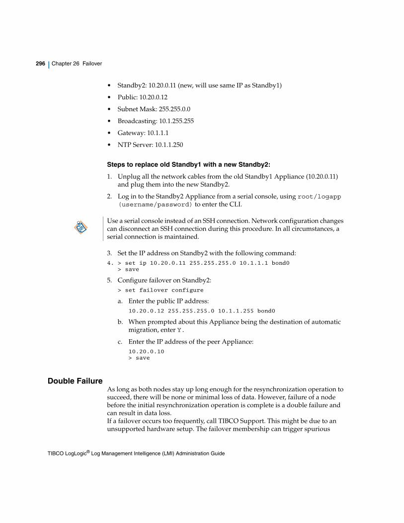
296 | Chapter 26 Failover
• Standby2: 10.20.0.11 (new, will use same IP as Standby1)
• Public: 10.20.0.12
• Subnet Mask: 255.255.0.0
• Broadcasting: 10.1.255.255
• Gateway: 10.1.1.1
• NTP Server: 10.1.1.250
Steps to replace old Standby1 with a new Standby2:
1. Unplug all the network cables from the old Standby1 Appliance (10.20.0.11) and plug them into the new Standby2.
2. Log in to the Standby2 Appliance from a serial console, using root/logapp (username/password) to enter the CLI.
3. Set the IP address on Standby2 with the following command:4. > set ip 10.20.0.11 255.255.255.0 10.1.1.1 bond0
> save
5. Configure failover on Standby2:> set failover configure
a. Enter the public IP address: 10.20.0.12 255.255.255.0 10.1.1.255 bond0
b. When prompted about this Appliance being the destination of automatic migration, enter Y.
c. Enter the IP address of the peer Appliance: 10.20.0.10 > save
Double Failure As long as both nodes stay up long enough for the resynchronization operation to succeed, there will be none or minimal loss of data. However, failure of a node before the initial resynchronization operation is complete is a double failure and can result in data loss. If a failover occurs too frequently, call TIBCO Support. This might be due to an unsupported hardware setup. The failover membership can trigger spurious
Use a serial console instead of an SSH connection. Network configuration changes can disconnect an SSH connection during this procedure. In all circumstances, a serial connection is maintained.
TIBCO LogLogic® Log Management Intelligence (LMI) Administration Guide

Node Failure and Recovery | 297
failover if the network bandwidth is insufficient. It is good practice to use only Gigabit Ethernet connections for the HA replication traffic.
TIBCO LogLogic® Log Management Intelligence (LMI) Administration Guide

298 | Chapter 26 Failover
TIBCO LogLogic® Log Management Intelligence (LMI) Administration Guide
| 299
Chapter 27 Migrating Data Between Appliances
Data migration lets you migrate data and configuration settings from one LogLogic Appliance to another.
You can migrate data between any two LogLogic Appliances of the same family (LX to LX, MX to MX, or ST to ST).
The data migration solution is similar to replacing an Appliance with a new one in a high availability configuration via failover. Like a failover from an active to a standby Appliance, during migration the data is resynchronized while logs are still collected, thus minimizing down time. For more information on failover, see Chapter 26, Failover.
Topics
• When to Migrate Data on page 300
• Migrating Data From One Appliance to Another on page 302
TIBCO LogLogic® Log Management Intelligence (LMI) Administration Guide

300 | Chapter 27 Migrating Data Between Appliances
When to Migrate Data
The primary purpose of the data migration solution is to migrate log data and configuration settings from one LogLogic Appliance to another.
It is particularly useful when upgrading from earlier LogLogic Appliance models to newer models.
When migrating data, the following network connection configurations are supported:
• eth0 to eth0
• bond0 to bond0
• split mode (eth0 continues to collect data during migration from eth1 to eth1)
Do not perform backup or restore operations when data migration is in progress.
Table 17 Supported Data Migration Path
From/To LX1025R1/R2 LX4025R1/R2 ST2025R1/R2-SAN ST4025R1/R2 EVA
LX1025 Yes
LX4025 Yes
ST1025 Yes
ST2025-SAN Yes
ST4025 Yes
MX3025 Yes
MX4025 Yes
EVA Yes
Similar to the LX820 models, Data Migration is not supported on LX825 models. For MX models migrating data to an LX4025R1 appliance, you will need to increase the data retention on the LX4025R1 to match that of the MX prior to performing data migration.
TIBCO LogLogic® Log Management Intelligence (LMI) Administration Guide

When to Migrate Data | 301
Data Migration on High Availability AppliancesData migration is automatically performed whenever you configure failover on an Appliance. This migration is necessary to ensure both Appliances’ data is in sync. For more information and procedures for failover, see Failover on page 275.
TIBCO LogLogic® Log Management Intelligence (LMI) Administration Guide
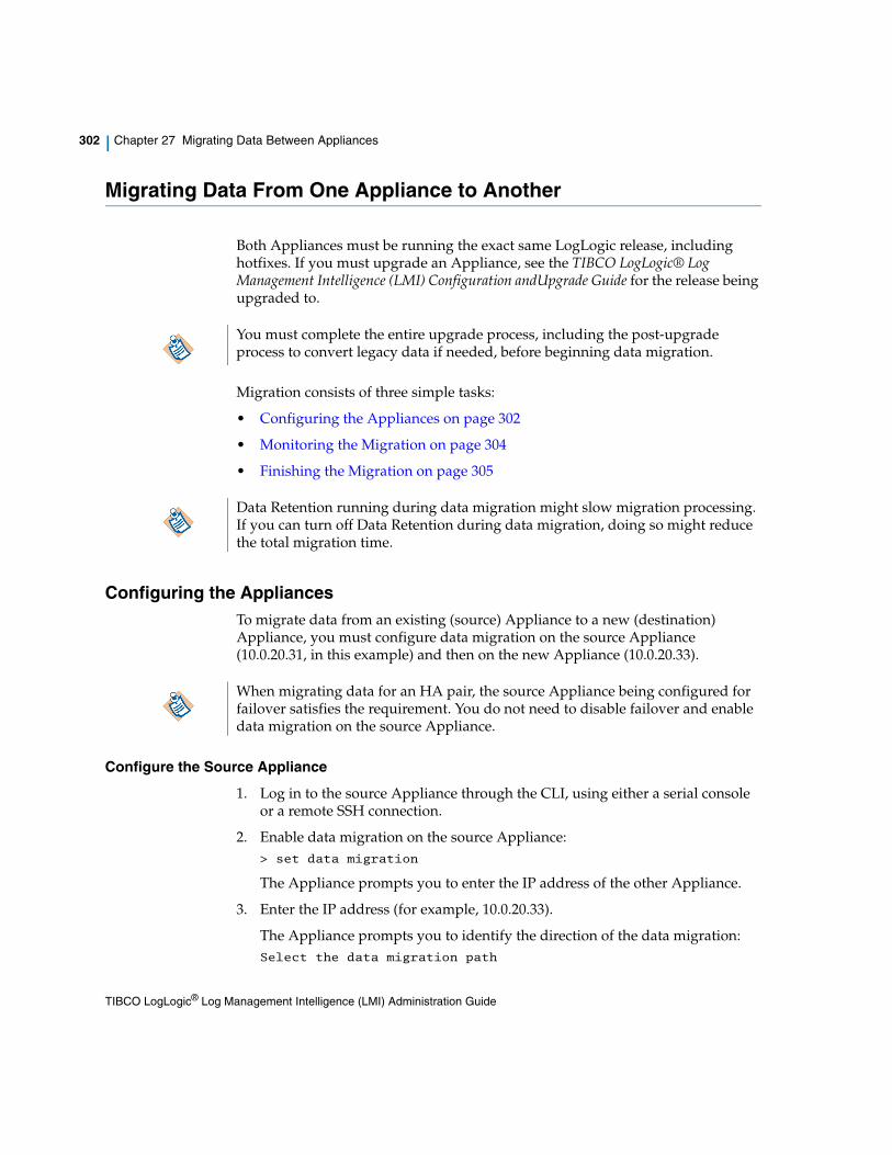
302 | Chapter 27 Migrating Data Between Appliances
Migrating Data From One Appliance to Another
Both Appliances must be running the exact same LogLogic release, including hotfixes. If you must upgrade an Appliance, see the TIBCO LogLogic® Log Management Intelligence (LMI) Configuration andUpgrade Guide for the release being upgraded to.
Migration consists of three simple tasks:
• Configuring the Appliances on page 302
• Monitoring the Migration on page 304
• Finishing the Migration on page 305
Configuring the AppliancesTo migrate data from an existing (source) Appliance to a new (destination) Appliance, you must configure data migration on the source Appliance (10.0.20.31, in this example) and then on the new Appliance (10.0.20.33).
Configure the Source Appliance
1. Log in to the source Appliance through the CLI, using either a serial console or a remote SSH connection.
2. Enable data migration on the source Appliance:> set data migration
The Appliance prompts you to enter the IP address of the other Appliance.
3. Enter the IP address (for example, 10.0.20.33).
The Appliance prompts you to identify the direction of the data migration:Select the data migration path
You must complete the entire upgrade process, including the post-upgrade process to convert legacy data if needed, before beginning data migration.
Data Retention running during data migration might slow migration processing. If you can turn off Data Retention during data migration, doing so might reduce the total migration time.
When migrating data for an HA pair, the source Appliance being configured for failover satisfies the requirement. You do not need to disable failover and enable data migration on the source Appliance.
TIBCO LogLogic® Log Management Intelligence (LMI) Administration Guide

Migrating Data From One Appliance to Another | 303
0) Do not setup data migration1) This Appliance -> 10.0.20.33
2) 10.0.20.33 -> This Appliance
4. Enter 1.
The Appliance warns you that changes have not been saved.
5. Save the changes to apply the new configuration and restart the software:6. > save
The Appliance processes the changes, displaying the steps as they occur, and then informs you when it is done.
7. Log on to the source Appliance through the UI web server.
8. Verify the Appliance is correctly receiving and processing logs.
The dashboard reports an HA error because the new Appliance is not yet configured.
Configure the New Appliance
If you are migrating data to an existing Appliance, it is recommended to delete all existing data on that Appliance before performing a data migration to it.
1. Log in to the new Appliance through the CLI, using either a serial console or a remote SSH connection.
2. Enable data migration on the new Appliance:
> set data migration
The Appliance prompts you to enter the IP address of the other Appliance.
3. Enter the IP address (for example, 10.0.20.31).
The Appliance prompts you to identify the direction of the data migration:Select the sense of the data migration
0) Do not setup data migration1) This Appliance -> 10.0.20.31
2) 10.0.20.31 -> This Appliance
4. Enter 2.
The Appliance warns you that changes have not been saved.
5. Save the changes to apply the new configuration and restart the software:
I If you have multiple IP addresses you will be prompted to select the IP to use for High Availability.
TIBCO LogLogic® Log Management Intelligence (LMI) Administration Guide

304 | Chapter 27 Migrating Data Between Appliances
> save
The Appliance processes the changes, displaying the steps as they occur, and then informs you when it is done processing changes.
Data migration now begins. The data migration process has five phases, all of which are internal and do not require interaction:
1. Migration of the configuration database.
2. Initial migration of the BFQ files.
3. Migration of the parsed database tables.
4. Verification of the migrated BFQ files.
5. Final synchronization of the BFQ files, to capture recent modifications during migration processing.
Monitoring the MigrationTo configure a System Alert for when the migration is complete:
1. Log in to the source Appliance via the UI.
2. Choose Alerts > Manage Alert Rules from the menu.
3. In the Name column, select and click System Alert - Migration Complete.
4. Configure a Migration Complete alert with the settings you want.
When you receive the Migration Complete alert, you can remove the source Appliance.
You can optionally configure alerts to send email during a failure condition, such as active failover or resynchronization error. For more information on configuring alerts, see the TIBCO LogLogic® Log Management Intelligence (LMI) User Guide.
During migration, each time a user logs in to the UI or when the System Status page is accessed, a warning appears providing migration status:
I If you have multiple IP addresses you will be prompted to select the IP to use for High Availability.
During migration, the source appliance continues to collect logs. The disk capacity is limited to the lower of the two appliances., The maximum rate of incoming logs is limited to the source appliance, because logs are received by the source appliance.
TIBCO LogLogic® Log Management Intelligence (LMI) Administration Guide

Migrating Data From One Appliance to Another | 305
Figure 22 Migration Status warning
You can check the status of the migration at anytime on the UI dashboard. Detailed events are internally logged to record system history.
Finishing the MigrationAfter you receive a System Alert indicating that migration processing is complete, or the UI dashboard reports completion:
1. Log in to the new Appliance through the CLI.
2. Disable the data migration mode:> unset data migration
3. Reconfigure the new Appliance network settings:set ip private-ip-address netmask gateway [ifdev] [defaultgw]
For example:> set ip 10.1.1.177 255.255.0.0 10.1.255.255 bond0
The Appliance warns you that changes have not been saved.
4. Shut down the source Appliance. This is required now if the new Appliance is using the same network setting as the old Appliance.
5. On the new Appliance, save the new configuration (in step 3) and restart the software:> save
The Appliance processes the changes, displaying the steps as they occur, and then informs you when it is done processing changes.
The new Appliance is now collecting and processing logs instead of the source Appliance.
TIBCO LogLogic® Log Management Intelligence (LMI) Administration Guide

306 | Chapter 27 Migrating Data Between Appliances
Recovering from Failed MigrationStarting v6.1.0, LMI provides a way to recover stDataFiles and indexFiles tables if a failure occurs during the upgrade process.
Some data from these tables might be lost during the recovery process, because restore operations can only guarantee the integrity of the system up to the last backed up state. For the stDataFiles table, LMI tries to recover missing records along with next system cleansing process. However, for the indexFiles table, there is no way to recover missing records.
To retry migration after a migration failure, perform the following steps.
To recover stDataFiles1. cd /loglogic/scripts/innoDBConverter/
2. ./recoverStDataFiles
3. Wait for the completion message.
To recover indexFiles1. cd /loglogic/scripts/innoDBConverter/
2. ./recoverIndexFiles
3. Wait for the completion message.
TIBCO LogLogic® Log Management Intelligence (LMI) Administration Guide

| 307
Chapter 28 Updating Software and Using Diagnostics
Topics
• Updating Appliance Software on page 308
• RAID Status on page 309
• System Summary for Diagnostics on page 311
• Clearing Appliance Log Data on page 314
TIBCO LogLogic® Log Management Intelligence (LMI) Administration Guide

308 | Chapter 28 Updating Software and Using Diagnostics
Updating Appliance Software
From the Appliance UI, use Administration > File Update to update the software running on an Appliance. The new software version number displays in the top right corner of the System Status page.
Using File Update
Prerequisites for Using the File Update Feature
• Ensure you have at least 1GB of disk space available. To verify disk space, log in to the Appliance via the UI and on the System Status screen look at the Free column under Database Size.
• You must download the .tar and .sig files from the TIBCO Support Website and copy them to the /loglogic/update directory (create it if it does not yet exist) of the Appliance being upgraded.
To use File Update
1. Select a file from the Select File drop-down menu.
2. All available file updates are listed in the dropdown.
3. Click Update to begin the update.
The user must wait at least 1 day after a software upgrade before doing a backup, otherwise the backed up log data will be inconsistent with the platform software.
The system might reboot during the update
TIBCO LogLogic® Log Management Intelligence (LMI) Administration Guide

RAID Status | 309
RAID Status
Redundant Array of Inexpensive Drives (RAID) is a method of increasing data reliability by using groups (or 'arrays') of small hard drives to create a single large drive. There are several RAID configurations; LogLogic uses RAID 1, 5, 6, or 10, depending on the Appliance model.
Use the RAID Status tab to view a high level of the condition of available drives. The available drives are listed followed by the status for each drive. This tab shows only high level information.
This feature is available for:
• LX 825 - 2 drives: 2x1TB RAID 1
• LX 1025 - 2 drives: 2X1TB RAID 1
• LX 1025R2 - 2 drives: 2X1TB RAID 1
• LX 4025 - 8 drives: 8x1TB RAID 10
• LX 1025R1 - 2 drives: 2x1TB RAID 1
• LX 4025R1 - 8drives: 8x4TB RAID 10
• LX 4025R2 - 8 drives: 8X4TB RAID 10
• MX 3025 - 4 drives: 4x1TB RAID 10
• MX 4025 - 8 drives 8x1TB RAID 6
• ST 1025 - 2 drives: 2x1TB RAID 1
• ST 2025-SAN - 2 drives: 2x1TB RAID 1
• ST 4025 - 8 drives: 8x1TB RAID 6
• ST 2025-SANR1 - 8 drives: 8x1TB RAID 6
• ST 2025-SAN R2 - 8 drives: 8X1TB RAID 6
• ST 4025R1 - 8 drives: 8x4TB RAID 10
• ST 4025R2 - 8 drives: 8X4TB RAID 10
For all RAID Appliances, when a disk fails, a warning message displays and shows up on the Dashboards > System Status page. To set up an alert to notify you if a RAID disk failure occurs, see Creating and Managing Alerts in TIBCO LogLogic® Log Management Intelligence (LMI) User Guide.
For more information about the device configuration and hardware details, see the TIBCO LogLogic® Log Management Intelligence (LMI) Hardware Installation Guide.
TIBCO LogLogic® Log Management Intelligence (LMI) Administration Guide

310 | Chapter 28 Updating Software and Using Diagnostics
System Summary for Diagnostics
The Administration > System Summary tabs provide a variety of diagnostic information. These tabs should be used only by, or as instructed by, TIBCO Support.
To update the information on any tab, click Refresh.
Process ListUse the Process List to view a list of processes that are running on the Appliance.
Click Refresh to update the list.
NetworkUse the Network tab to view information about system configuration and operations. This tab lists specific details of the network interfaces on your Appliance. It should be used for diagnostic purposes only.
The following types of information displays about the Network:
• eth0—The first ethernet interface.
• eth1—The second ethernet interface.
• eth3—The fourth Ethernet interface
• bond0—Two Ethernet interfaces combined into a single bonded interface. See back of Appliance for bond0 label, or refer to the TIBCO LogLogic® Log Management Intelligence (LMI) Hardware Installation Guide.
• bond1—Two Ethernet interfaces combined into a single bonded interface. See back of Appliance for bond1 label, or refer to the TIBCO LogLogic® Log Management Intelligence (LMI) Hardware Installation Guide.
Click Refresh to update the list.
The number of Ethernet interfaces varies with Appliance model.
TIBCO LogLogic® Log Management Intelligence (LMI) Administration Guide

System Summary for Diagnostics | 311
SANUse the SAN tab to view information about Storage Area Network (SAN) settings and details for the ST 2025-SAN or ST 2025-SAN R1 appliance. This information should be used for diagnostic purposes only.
DB Table StatusUse the DB Table Status tab to view information about system operations. You can use this tab to easily view the status of the database tables used by your Appliance. For example, Rows, Avg_row_length, or data being used, which can indicate problems with the database. This tab should be used for diagnostic purposes only.
Click Refresh to update the list.
Centera Status (ST Only)Use the Centera Status tab to view current Centera configuration for the Appliance. Any changes to the Administration > Archive Configuration > Centera Configuration page displays in this status page once you click Update.
Click Refresh to update the list.
Kernel Ring BufUse the Kernel Ring Buf to view information about system operations. The information in the tab displays the last lines of the Appliances operating system log file. This tab should be used for diagnostic purposes only.
Click Refresh to update the list.
Restart/Reboot/ShutdownUse the following tabs for system wide operations:
• Application Restart—Restarts the services. This resets the message counters on the System Status page and the internal counters used for alert generation.
• Appliance Reboot—Reboots the appliance. The appliance returns the login page after rebooting completes.
In some cases, the value of Create_time may be displayed as Null. This is seen when no data is present in the table, and is expected due to the nature of the merge tables in the LMI database.
TIBCO LogLogic® Log Management Intelligence (LMI) Administration Guide

312 | Chapter 28 Updating Software and Using Diagnostics
• Appliance Shutdown—Shuts down the system. After shut down completes, the system is accessible only via the direct connect console.
Click Confirm to continue with the operation, or Cancel to terminate the operation.
TIBCO LogLogic® Log Management Intelligence (LMI) Administration Guide

Clearing Appliance Log Data | 313
Clearing Appliance Log Data
If necessary, you can remove all log data on the LogLogic Appliance. It is good practice to back up all log data on the Appliance before clearing log data, because once the log data is removed from the Appliance it cannot be recovered.
• On an LX or MX Appliance, use the Administration > Clear Log Data tab.
• On an ST Appliance, run the following CLI command:
/loglogic/tomcat/webapps/logapp20/WEB-INF/cgi/rttime "type=resetappliancelogs"
When the cleanup process starts, all active Appliance components, such as reports and alerts, are brought to a dormant state. All running components, such as reports, are shut down immediately.
• The clear log data operation can not be done in a HA environment. To clear log data from a node, first remove the node from the HA environment.
• An exception might be displayed on the user interface after the Clear Log Data operation is performed. For example, in any of the following scenarios:
— when the operation is in progress and the browser window is refreshed
— while loading the login page
— if multiple sessions are running simultaneously
If the exception is displayed, wait for the operation to finish and make sure engines have started, and then load the Login page in a browser.
TIBCO LogLogic® Log Management Intelligence (LMI) Administration Guide

314 | Chapter 28 Updating Software and Using Diagnostics
TIBCO LogLogic® Log Management Intelligence (LMI) Administration Guide

| 315
Chapter 29 Forwarding Data to TIBCO LogLogic® Unity
Data can be forwarded to a TIBCO LogLogic® Unity platform based on one or more rules.
Topics
• Forwarding Data to TIBCO LogLogic® Unity, page 316
TIBCO LogLogic® Log Management Intelligence (LMI) Administration Guide

316 | Chapter 29 Forwarding Data to TIBCO LogLogic® Unity
Forwarding Data to TIBCO LogLogic® Unity
An Appliance receiving messages from multiple log sources can be configured to forward some or all of the messages to a TIBCO LogLogic® Unity platform based on one or more rules.
The Event Distribution Client (EDC) allows for log data transfer from a LogLogic LMI platform to a TIBCO LogLogic® Unity platform. The EDC remains in standby mode until a user creates a rule. Once a rule is created EDC applies the filters and starts sending events.
For more information regarding message routing refer to Chapter 12, Forwarding Logs to Other Appliances (Routing), on page 97.
Creating a New Outbound Routing RulePrerequisite:
• Search Filter
For more information regarding filters refer to "Adding a Search Filter" section in the TIBCO LogLogic® Log Management Intelligence (LMI) User Guide.
To create a New Outbound Routing Rule:
1. Access Administration > Message Routing from the navigation menu.
2. Click the Create Outbound Data Rule button to create a new routing rule.
3. In the Rule Name field, enter a name for the routing rule and click Next.
4. Under Add Log Sources section, click the down arrow next to Select and pick a log source filter.
5. Select a log source by clicking its name.
6. Click <<Add selected log sources to move the selected log sources to the left.
7. Click Next.
8. From the Destination Type drop-down menu, select LogLogic Unity.
This selection will grey out the Destination Port, Protocol, Format Settings, LogLogic Fowarding Settings and Other Settings as they do not apply to TIBCO LogLogic® Unity.
LMI does not support log forwarding of global groups.
TIBCO LogLogic® Log Management Intelligence (LMI) Administration Guide

Forwarding Data to TIBCO LogLogic® Unity | 317
9. In the Connect Str: field, type the connectstring of the destination TIBCO LogLogic® Unity to which you want to forward messages. (For example, 10.20.20.50:9600).
10. Select the Enable checkbox to activate message forwarding.
11. In the TIBCO LogLogic® Unity Forwarding Settings select the Unity Domain (this domain will route data to Unity), shared is the default. You can specify a new name in the text box, however the domain name entered here must exist in Unity.
In TIBCO LogLogic® Unity, a domain is an area of storage for events and their associated data. You can split data of different nature or intended usage into multiple domains. You can search for events from a specific domain or multiple domains from the Search tab. Similarly, you can specify which data should be used for alerting. In TIBCO LogLogic® Unity you can select from a list of pre-configured domains or define a new domain. The default is set to shared. The three pre-defined domains are: shared, internal, and samples. For more information refer to the TIBCO LogLogic® Unity User’s Guide.
12. Click Next to define the message Filters including Severity, and Facility or click Finish to accept the default message filters.
13. Select an existing search filter from the Search Filter drop-down menu.
14. Click the Forward all except filter matches checkbox to forward those messages that do not match the defined search filter.
15. Select the Message Severity and Facility filters that you wish to select or Select All if you want everything forwarded.
By default, all checkboxes are selected for syslog-based log sources.
The facility specifies the subsystem that produced the message. For example, all mail programs log with the mail facility (LOG_MAIL) if they log using syslog.
16. Click Finish. The Message Routing screen appears showing the newly added Routing Rule.
Adding Destinations to All Sources RuleTo add a destination to All Sources Rule:
1. Access Administration > Message Routing from the navigation menu.
2. Click the Add Destination link.
The port number 9600 must be specified regardless of the IP address you use, as 9600 is the zookeeper port on TIBCO LogLogic® Unity.
TIBCO LogLogic® Log Management Intelligence (LMI) Administration Guide
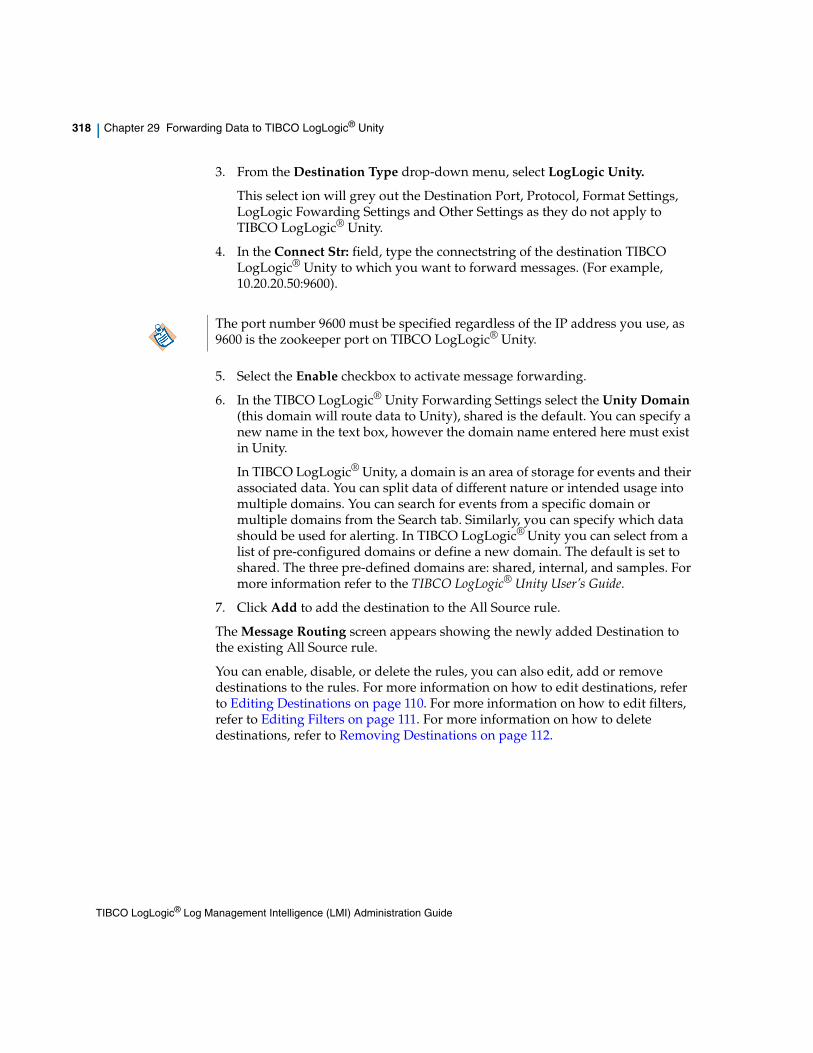
318 | Chapter 29 Forwarding Data to TIBCO LogLogic® Unity
3. From the Destination Type drop-down menu, select LogLogic Unity.
This select ion will grey out the Destination Port, Protocol, Format Settings, LogLogic Fowarding Settings and Other Settings as they do not apply to TIBCO LogLogic® Unity.
4. In the Connect Str: field, type the connectstring of the destination TIBCO LogLogic® Unity to which you want to forward messages. (For example, 10.20.20.50:9600).
5. Select the Enable checkbox to activate message forwarding.
6. In the TIBCO LogLogic® Unity Forwarding Settings select the Unity Domain (this domain will route data to Unity), shared is the default. You can specify a new name in the text box, however the domain name entered here must exist in Unity.
In TIBCO LogLogic® Unity, a domain is an area of storage for events and their associated data. You can split data of different nature or intended usage into multiple domains. You can search for events from a specific domain or multiple domains from the Search tab. Similarly, you can specify which data should be used for alerting. In TIBCO LogLogic® Unity you can select from a list of pre-configured domains or define a new domain. The default is set to shared. The three pre-defined domains are: shared, internal, and samples. For more information refer to the TIBCO LogLogic® Unity User’s Guide.
7. Click Add to add the destination to the All Source rule.
The Message Routing screen appears showing the newly added Destination to the existing All Source rule.
You can enable, disable, or delete the rules, you can also edit, add or remove destinations to the rules. For more information on how to edit destinations, refer to Editing Destinations on page 110. For more information on how to edit filters, refer to Editing Filters on page 111. For more information on how to delete destinations, refer to Removing Destinations on page 112.
The port number 9600 must be specified regardless of the IP address you use, as 9600 is the zookeeper port on TIBCO LogLogic® Unity.
TIBCO LogLogic® Log Management Intelligence (LMI) Administration Guide

| 319
Chapter 30 IPv6 Support
Topics
• About IPv6 on page 320
• IPv6 Support Matrix on page 323
• Configuring Oracle JDBC Driver for IPv6 Support on page 324
TIBCO LogLogic® Log Management Intelligence (LMI) Administration Guide

320 | Chapter 30 IPv6 Support
About IPv6
Internet Protocol version 6 (IPv6) is the latest version of the Internet Protocol (IP), and provides an identification and location system for computers on networks and routes traffic across the Internet.
IPv6 permits hierarchical address allocation methods that facilitate route aggregation across the Internet, and thus limit the expansion of routing tables. The use of multicast addressing is expanded and simplified, and provides additional optimization for the delivery of services.
IPv6 is based on IP but with a much larger address space and improvements such as a simplified main header and extension headers. The IPv6 address space allows networks to scale and provide global reachability.
The primary motivation for IPv6 is the need to meet the demand for globally unique IP addresses. IPv6 quadruples the number of network address bits from 32 bits (in IPv4) to 128 bits, which provides more than enough globally unique IP addresses for every networked device on the planet. By being globally unique, IPv6 addresses inherently enable global reachability and end-to-end security for networked devices, functionality that is crucial to the applications and services that are driving the demand for the addresses. Additionally, the flexibility of the IPv6 address space reduces the need for private addresses and the use of Network Address Translation (NAT); therefore, IPv6 enables new application protocols that do not require special processing by border routers at the edge of networks.
IPv6 Address FormatsIPv6 addresses are represented as eight groups of four hexadecimal digits separated by colons (:) in the format: x:x:x:x:x:x:x:x. Following are two examples of IPv6 addresses:
2001:DB8:7654:3210:FEDC:BA98:7654:3210
2001:0db8:85a3:0042:1000:8a2e:0370:7334
It is common for IPv6 addresses to contain successive hexadecimal fields of zeros. To make IPv6 addresses less cumbersome, two colons (::) may be used to compress successive hexadecimal fields of zeros at the beginning, middle, or end of an IPv6 address (the colons represent successive hexadecimal fields of zeros). Table 1 lists compressed IPv6 address formats.
A double colon may be used as part of the ipv6-address argument when consecutive 16-bit values are denoted as zero. You can configure multiple IPv6 addresses per interfaces, but only one link-local address.
TIBCO LogLogic® Log Management Intelligence (LMI) Administration Guide

About IPv6 | 321
LogLogic Support for IPv6This section provides details to the LogLogic IPv6 implementation.
LogLogic’s implementation of IPv6 supports:
• Native connectivity to log sources.
• Regex and Index searches.
• Parsed reports against IPv6 Log Sources.
• Collection of IPv6 data from TIBCO LogLogic® Universal Collector (UC) 2.6 and above.
• Network configuration:
IPv6 and IPv4 addresses can be assigned to the same or different interfaces.Note: Dual stack IPv6 support is not available for HA VIP interface.
• Collection from IPv4 sources by an appliance with an IPv6 address:
Direct collection is only possible if the appliance is accessible from an IPv4 address; either by assigning an appropriate v4 address, or by providing network address translation externally. In the case of external translation, the source address reported for the source devices is entirely dependent on the external translation performed.
• Forwarding log messages between IPv4 and IPv6:
Forwarding from an IPv6 addressable appliance to an IPv4-only appliance is only possible if the forwarding appliance has v4 connectivity; either by assigning an appropriate v4 address, or by providing external network address translation.
Apparent source address of traffic forwarded to an IPv4 address:
— IPv4 source: any protocol: will always appear as the original source address, but an IPv6 notation will be added as a prefix.
— IPv6 source: lltcp LMI >= 5.6: will appear as the original source address.
— IPv6 source: lltcp LMI < 5.6: will appear as the last 4 bytes of the original source address.
— IPv6 source: syslog: will appear as the last 4 bytes of the original source address.
TIBCO LogLogic® Log Management Intelligence (LMI) Administration Guide

322 | Chapter 30 IPv6 Support
Apparent source address of traffic forwarded to an IPv6 address:
— IPv6 source: any protocol: will always appear as the original source address.
— IPv4 source: lltcp LMI >= 5.6: will appear as the original source address.
— IPv4 source: lltcp LMI < 5.6: not applicable.
— IPv4 source: syslog: should appear as the original source address, this is not recommended (relies on theoretically illegal v4-mapped IPv6 source address in UDP packets) as some network routers may chose to discard such packets.
• Display of IPv4 source addresses:
In most cases IPv4 addresses are displayed, emailed, or reported in their traditional dotted-decimal notation. The following exceptions exist (displayed as v4-mapped addresses in V6 notation):
— Real-time viewer
— recent messages
— unapproved messages
— address appearing in the automatically generated names of auto discover devices
— address appearing in backup file names
• IPv6 addresses for external servers:
The following external services are supported with IPv6 addresses:
— NFS and SCP backup
— NFS and SCP archival
— NTP
— DNS (including resolution of names to v6 addresses)
— SMTP
— Active Directory
• Static routes:
LMI v5.6 supports both v4 and v6 static routes.
IPv6 addresses not supported for:
• Checkpoint LEA
• Parsing of address strings within log messages
TIBCO LogLogic® Log Management Intelligence (LMI) Administration Guide
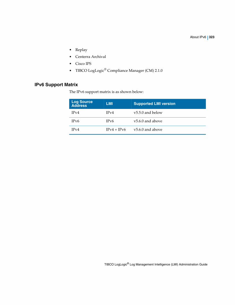
About IPv6 | 323
• Replay
• Centerra Archival
• Cisco IPS
• TIBCO LogLogic® Compliance Manager (CM) 2.1.0
IPv6 Support MatrixThe IPv6 support matrix is as shown below:
Log Source Address LMI Supported LMI version
IPv4 IPv4 v5.5.0 and below
IPv6 IPv6 v5.6.0 and above
IPv4 IPv4 + IPv6 v5.6.0 and above
TIBCO LogLogic® Log Management Intelligence (LMI) Administration Guide

324 | Chapter 30 IPv6 Support
Configuring Oracle JDBC Driver for IPv6 Support
1. Download a supported Oracle JDBC driver (11g or 12c).
2. Rename the driver to oracle-10gr2-ojdbc14.jar.
3. SSH to LMI and rename the oracle-10gr2-ojdbc14.jar to oracle-10gr2-ojdbc14.org under /loglogic/tomcat/webapps/logapp20/WEB-INF/lib/ .
4. Copy the new oracle-10gr2-ojdbc14.org file to LMI under /loglogic/tomcat/webapps/logapp20/WEB-INF/lib on LMI. Make sure that you replace the original file.
5. Stop Mtask.
6. Restart Mtask.
TIBCO LogLogic® Log Management Intelligence (LMI) Administration Guide

| 325
Appendix A Command Line Interface (CLI)
This appendix describes the tasks you can perform using the console command line interface (CLI) to set up, configure, and maintain a LogLogic Appliance. The console is the terminal for accessing the appliance.
For detailed help on a specific command, type:
help cmd
or
? cmd
Topics
• Connecting to the Appliance on page 326
• exit Command on page 327
• network Command on page 328
• raid Command on page 330
• plugin Command on page 331
• save Command on page 332
• set Command on page 333
• show Command on page 338
• swraid Command on page 340
• system Command on page 341
• unset Command on page 347
• watch Command on page 348
• lmiedc Command on page 349
TIBCO LogLogic® Log Management Intelligence (LMI) Administration Guide

326 | Appendix A Command Line Interface (CLI)
Connecting to the Appliance
Before you can use any command line options, you must connect to the Appliance. Use a laptop or other terminal device to make this connection. All commands are logged internally to enhance Appliance security.
Connecting to the Appliance
1. Use a null modem cable to connect the Appliance to COM1.
2. Open a terminal utility.
3. Set the communication setting from the terminal login dialog. For example:
9600 baud, Null, 8 bit, 1
baud rate: 9600
data bits: 8
parity: none
stop bits: 1
4. Log in to the Appliance in the console mode.
5. From the terminal program, log in as user root with the default password logapp. There are two passwords for shell and CLI. By default, both have the same password.
Ping the Appliance. You must be able to successfully ping the Appliance.
It is good practice to connect to the CLI via a serial console, and not using SSH, when issuing network configuration commands such as set failover. Network configuration changes might reconfigure the network card, disconnecting an SSH connection.
Change the default password for the CLI and shell login. To change the password, type system passwd Usage > at the command prompt and follow the prompts.
TIBCO LogLogic® Log Management Intelligence (LMI) Administration Guide

exit Command | 327
exit Command
The exit command exits from the login shell and system.
This command has no arguments or keywords.
ExampleTo exit the session:
> exit
TIBCO LogLogic® Log Management Intelligence (LMI) Administration Guide

328 | Appendix A Command Line Interface (CLI)
network Command
The network command has options that let you activate, deactivate, or restart all network interface(s), or ping a specific system on the network.
Type the following command from your command line.
network [ start | stop | restart | ping ip-address ]
The network ping command determines network connectivity. When using ping for fault isolation, you initially run it on the local host, to verify that the local network interface is up and running. Then, ping hosts and gateways further and further away.
The ping command uses the ICMP protocols mandatory ECHO_REQUEST datagram to elicit an ICMP ECHO_RESPONSE from a host or gateway. ECHO_REQUEST datagrams (ping) have an IP and ICMP header, followed by a strict time value and then an arbitrary number of pad bytes used to fill out the packet.
Examples
To restart all network interfaces:
> network restartRemoving default gateway...[ OK ]Bringing down the eth0 interface...[ OK ]Bringing down the eth1 interface...[ OK ]Bringing up the eth0 interface...[ OK ]Bringing up the eth1 interface...
[ OK ]Setting up default gateway...
Table 18 network Syntax Parameters
Parameter Description
start Activates network interface(s).
stop Deactivates network interface(s).
restart Deactivates and then activates network interface(s).
ping ip-address Pings the specified IP address.
TIBCO LogLogic® Log Management Intelligence (LMI) Administration Guide

network Command | 329
[ OK ]
To determine network connectivity with the system that has IP address 10.1.1.222:
> network ping 10.1.1.222PING 10.1.1.222 (10.1.1.222): 56 octets data64 octets from 10.1.1.222: icmp_seq=0 ttl=64 time=2.1 ms64 octets from 10.1.1.222: icmp_seq=1 ttl=64 time=1.0 ms64 octets from 10.1.1.222: icmp_seq=2 ttl=64 time=0.8 ms64 octets from 10.1.1.222: icmp_seq=3 ttl=64 time=1.2 ms64 octets from 10.1.1.222: icmp_seq=4 ttl=64 time=1.3 ms
--- 10.1.1.222 ping statistics ---5 packets transmitted, 5 packets received, 0% packet lossround-trip min/avg/max = 0.8/1.2/2.1 ms
TIBCO LogLogic® Log Management Intelligence (LMI) Administration Guide

330 | Appendix A Command Line Interface (CLI)
raid Command
This command shows hard drive information of the hardware RAID.
The raid command displays its submenu as shown below.> raid//localhost> ?
Copyright(c) 2004, 2005 Applied Micro Circuits Corporation(AMCC). All rights reserved.
AMCC/3ware CLI (version 2.00.03.008)
Commands Description-------------------------------------------------------------------info Displays information about controller(s), unit(s) and port(s).maint Performs maintenance operations on controller(s), unit(s) and ports.alarms Displays current AENs.set Displays or modifies controller and unit settings.sched Schedules bachground tasks on controller(s) (9000 series)quit Exits the CLI. ---- New Command Syntax ----focus Changes from one object to another. For Interactive Mode Only!show Displays information about controller(s), unit(s) and port(s).flush Flush write cache data to units in the system.rescan Rescan all empty ports for new unit(s) and disk(s).commit Commit dirty DCB to storage on controller(s). (Windows only)/cx Controller specific commands./cx/ux Unit specific commands./cx/px Port specific commands./cx/bbu BBU specific commands. (9000 only)
Type help command to get more details about a particular command.
You must be careful before changing any raid setup
TIBCO LogLogic® Log Management Intelligence (LMI) Administration Guide

plugin Command | 331
plugin Command
The plugin command has options that let you register, unregister, activate, or deactivate, new plugins for device.
Type the following command from your command line.
plugin [ add | del | enable | disable | view | view all ]
Table 19 network Syntax Parameters
Parameter Description
add<devID> <devFormat> | <prog> <execType> | <progType> | <keyIn> <keyout>
Registers new plugin for device (deviceID, devformat).
del <devID> | <devFormat>
Unregisters plugin for device (deviceID, devFormat)
enable <devID> <devFormat>
(Re)activates plugin registered for (devID, devFormat)
disable <devID> <devFormat>
Deactivates plugin registered for (devID, devFormat)
view <devID> <devFormat>
Displays status of plugin registered for (devID, devFormat)
view all Displays status of all registered plugins where:
<devID> - numerical device ID
<devForamt> - numerical device format ID
<prog> - plugin executable path name
<execType> - [binary | shell | script |...]
<progType> - [0 |1 |2 ], use 1 for now
<keyIn> - plugin input format specific key
<keyOut> - plugin output format specific key
TIBCO LogLogic® Log Management Intelligence (LMI) Administration Guide

332 | Appendix A Command Line Interface (CLI)
save Command
The save command saves system configuration settings such as setting IP or failover.
The format to use this command is:
save
ExampleTo save your system configuration settings to disk:
> save
TIBCO LogLogic® Log Management Intelligence (LMI) Administration Guide

set Command | 333
set Command
The set command sets up the system IP address, DNS server IP address, Ethernet type, system clock and time zone, NTP server IP address, and failover. Once these tasks are complete you can access the Appliance through the UI.
Type the following command from your command line.
set [ clock | data migration | digest | dns | ethn | failover | ip | ipv6 | ntpserver | regexsearches | reverse_forward | strong_passwd | timezone ]
Set up your failover system before using the Appliance(s).
Table 20 set Syntax Parameters
Parameter Description
clock Sets the system date and time. set clock takes an option in the format: MMDDhhmm[[CC]YY][.ss]
data migration Configures the Appliance for data migration. After entering the command, the Appliance prompts you to identify which migration path to use. You must run the command on both the Appliance being migrated from and to.
digest Sets the appliance SHA Digest. The default is the 128-bit MD5 Digest. If the digest setting is changed, the Appliance will be restarted to synchronize the log data collection processes to use the new SHA Digest.
Usage of the 256-bit SHA2 Digest can reduce the maximum message handling rate of the Appliance up to 20%.
The command takes one of the following options: SHA256 | MD5 | default.
dns Queries the Internet Domain Name System (DNS) for host information. This command helps to convert host names into IP addresses and vice versa.
This command takes one option: dns-server-ip-address
ethn Changes network card settings. n is the number of the interface (eth0, eth1, etc.).
This command takes one of the following options: [ 100baseTx-FD | 100baseTx-HD | 10baseT-FD | 10baseT-HD | 1000baseTx-FD | 1000baseTx-HD | auto ]
TIBCO LogLogic® Log Management Intelligence (LMI) Administration Guide

334 | Appendix A Command Line Interface (CLI)
failover Assigns or resets failover active and standby Appliance roles. For more information, see Failover on page 275.
This command takes either of two options: configure | disable
The command prompts you for several options before taking certain actions.
ip Configures the kernel-resident network interfaces on the Appliance.This command takes several options: ip-address netmask gateway [ifdev] [defaultgw]
ifdev specifies either eth0, eth1, eth2, or bond0. The default is bond0.
defaultgw specifies the default gateway. Optional for specific NICs, but one NIC must be specified. The last gateway specified in defaultgw is in effect.
Note: The defaultgw keyword no longer has any effect and is allowed only for backward compatibility.
ipv6 Configures the kernel-resident network interfaces on the Appliance with IPv6 address.
This command takes several options: ipv6-address ipv6-prefix gateway [ifdev] [defaultgw]
ifdev specifies the network interface name or bond interface, like eth0, eth1, eth2, or bond0.
defaultgw specifies the default gateway. Optional for specific NICs, but one NIC must be specified. The last gateway specified in defaultgw is in effect.
Note: The defaultgw keyword no longer has any effect and is allowed only for backward compatibility.
ntpserver Sets the network time server.
This command takes either of two options: ipaddress | hostname
regexsearches Sets the number of simultaneous regular expression searches that the Appliance can run.
This command takes one option: limit
Table 20 set Syntax Parameters (Cont’d)
Parameter Description
TIBCO LogLogic® Log Management Intelligence (LMI) Administration Guide

set Command | 335
reverse_forward [ disable | tunnel_init on| tunnel_init off| tunnel_init add <ip_address>|tunnel_init delete <ip_address>| tunnel_accept [on|off] ]
disable - Disables reverse tunnel.
tunnel_init on - The appliance will try to initiate tunnels to the partners configured.
tunnel_init off - The appliance will not try to initiate tunnels.
tunnel_init add <ip_address> - To add a LogLogic Appliance IP address to initiate a tunnel to.
tunnel_init delete <ip_address> - To remove the tunnel to the LogLogic Appliance with the specified IP address.
tunnel_accept [on|off] - The appliance will [accept not} tunnel connections.
strong_passwd [ enable | disable | settings | expiration ]
Controls the use of strong passwords for user authentication via the CLI on the Appliance. (To set strong passwords for UI access, see Managing System Settings on page 201.)
enable - turns on the requirement of strong passwords for Appliance users
disable - turns off the requirement of strong passwords for Appliance users
settings - sets the strong password requirements for the Appliance. This command requires five options, as follows:
settings lowermin uppermin digitsmin nonalphanum minlength
lowermin - Minimum required lowercase letters (default and minimum = 1)
uppermin - Minimum required uppercase letters (default and minimum = 1)
digitsmin - Minimum number of numeric digits (default and minimum = 1)
nonalphanum - Minimum number of non-alphanumeric characters (default and minimum = 1)
minlength - Minimum number of total characters in the password (default = 15; minimum is 6 or the sum of the other four settings, whichever is greater)
expiration - the number of days after which a user password expires on the Appliance (1 through 99999 or never)
After disabling strong passwords, all settings are retained, but are only effective when strong passwords are enabled.
timezone Sets the time zone conversion. A time zone table displays with all possible selections. Enter a selection from this time zone table.
Table 20 set Syntax Parameters (Cont’d)
Parameter Description
TIBCO LogLogic® Log Management Intelligence (LMI) Administration Guide

336 | Appendix A Command Line Interface (CLI)
Examples
To set up a failover configuration for your Appliances:
On the active Appliance:
> set failover configureEnter the public Ip address of the clusterin the form <ip> <netmask> <broadcast>:CHANGES HAVE NOT BEEN SAVED!> saveWriting changes to disk...Removing default gateway...Bringing down the eth0 interface...Bringing down the eth1 interface...Bringing up the eth0 interface...Bringing up the eth1 interface...Setting up default gateway...Bringing down the eth1 interface...Bringing up the eth1 interface...done.On the standby Appliance:
> set failover configureCHANGES HAVE NOT BEEN SAVED!> saveWriting changes to disk...Removing default gateway...Bringing down the bond0 interface...Bringing up the eth0 interface...Setting up default gateway...Bringing down the eth1 interface...Bringing up the eth1 interface...done.
To disable the failover configuration:
On the Standby system:
> set failover disable> save
Please note that when using SHA256 instead of MD5 message digests, Appliance performance may be reduced by as much as 20%.
It is good practice to connect to the CLI via a serial console, and not using SSH, when issuing network configuration commands such as set failover. Network configuration changes might reconfigure the network card, disconnecting an SSH connection.
TIBCO LogLogic® Log Management Intelligence (LMI) Administration Guide

set Command | 337
Writing changes to disk...Removing default gateway...Bringing down the eth0 interface...Bringing down the eth1 interface...Bringing up the bond0 interface...Setting up default gateway...done.On the Active system:
> set failover disable> saveWriting changes to disk...Removing default gateway...Bringing down the eth0 interface...Bringing down the eth1 interface...Bringing up the bond0 interface...Setting up default gateway...done.
To set up network IP addresses for Ethernet interface 0:
> set ip 10.1.1.10 255.255.255.0 10.1.1.255 eth1> show changesCurrent changes that have not been saved:ip address eth0 10.1.1.10 255.255.255.0 10.1.1.255 CHANGES HAVE NOT BE SAVED! > save
To enable strong passwords and set each character minimum to 2, total minimum to 8, and expiration to 90:
> set strong_passwd enable> set strong_passwd settings 2 2 2 2 8> set strong_passwd expiration 90
TIBCO LogLogic® Log Management Intelligence (LMI) Administration Guide

338 | Appendix A Command Line Interface (CLI)
show Command
The show command display the status of the current system interface information that is stored on the disk, history of changes made during this session, pending changes not yet saved, and current system date and time.
Type the following command from your command line.
show [ current | digest | history | changes | date | regexsearches | reverse_forward | san_ports | san_ devices | strong_passwd ]
Examples
To show the current date and time on an Appliance:> show dateCurrent Time:Wed Jul 7 22:09:44 CDT 2004
Table 21 show Syntax Parameters
Parameter Description
current Current interface information stored on disk.
digest Shows the current SHA Digest being used by the Appliance.
history History of saved changes for the current session.
changes Pending changes that are not yet saved.
date Current system date and time.
regexsearches Shows the current simultaneous regular expression searches allowed, and the maximum number of simultaneous regular expression searches.
reverse_forward Shows the status of tunnel_accept [on|off], tunnel_init [on|off], partner IPs, and reverse forwarded status.
san_ports Shows SAN interface information.
san_devices Shows attached SAN devices.
strong_passwd Current settings for strong password requirements on the Appliance
TIBCO LogLogic® Log Management Intelligence (LMI) Administration Guide

show Command | 339
To show the current strong password settings on an Appliance:> show strong_passwdStrong password: disabledStrong password settings: The minimum number of lower case letters: 1 The minimum number of upper case letters: 1 The minimum number of digits: 1 The minimum number of non-alphanumeric characters: 1 The minimum password length: 6 Require password change after (days): never
TIBCO LogLogic® Log Management Intelligence (LMI) Administration Guide

340 | Appendix A Command Line Interface (CLI)
swraid Command
The swraid command displays the status of software RAID devices.
Type the following command from your command line.swraid
Examples
For software-raided model:> swraidPersonalities : [raid1]md2 : active raid1 sdb2[1] sda2[0] 2097088 blocks [2/2] [UU]
md3 : active raid1 sdb3[1] sda3[0] 972568192 blocks [2/2] [UU]
md1 : active raid1 sdb1[1] sda1[0] 2096064 blocks [2/2] [UU]
unused devices: <none>
For non-software-raided model:> swraidswraid : No RAIDs defined
TIBCO LogLogic® Log Management Intelligence (LMI) Administration Guide

system Command | 341
system Command
The system command implements system-wide changes.
Type the following command from your command line.
system [ access | data_client | halt | iptables | keycopy | passwd | reboot | secureuldp | update | fsck | sshkey_passphrase | logu | monthly_index]
Table 22 system Syntax Parameters
Parameter Description
access Grants full access to the application.
When Data Privacy mode is disabled, only one password is required to gain the access. The password can be changed using the system passwd command.
When Data Privacy mode is enabled, the two Security Keys will be required to gain access. You cannot change the Security Keys using the system passwd command. However, you can use the Web UI (from Administration > System Settings > General > Data Privacy Options) to reset your Security Keys, see Data Privacy Options on page 207.
data_client
[ add<username> | delete <username> | list]
add <username> - Creates a new account, the following constraints apply to usernames:
— The first character of the username must be lower/upper case letter, or a number.
— All characters, except the first character, must be lower/upper case letters, numbers, underscore character ('_') or period character ('.').
delete <username> - Deletes the existing user account
list - Displays all existing user accounts
halt Halts the Appliance.
iptables [ on | off ] Enables (on) or disables (off) the Appliance iptables. This can be used for Firewall Settings.
keycopy Copies the LogLogic product family public key to establish secure file transfer access with another server. The public key is used for file authentication when transferring files using the secure protocols SCP or SFTP.
TIBCO LogLogic® Log Management Intelligence (LMI) Administration Guide

342 | Appendix A Command Line Interface (CLI)
passwd [ cli | shell ] Changes the password for the CLI or system account. If an old password is present, the system prompts you for the old password and compares it against the stored password.
After the system authenticates the user, password aging information is checked to see if the user is permitted to change their password. If the user is authenticated, the system prompts for a replacement password. If the password is accepted, passwd prompts again and compares the second entry against the first. Both entries must match to successfully change the password.
This command with no option means change the password for CLI or shell access.
reboot Reboots the Appliance.
secureuldp
[ create csr | install rootCA | install certificate | delete rootCA | delete certificate | show csr]
create csr - Creates certificate signing request.
install rootCA - Parses and installs rootCA certificate.
install certificate - Parses and installs certificate.
delete rootCA - Deletes rootCA certificate.
delete certificated - Deletes certificate from the appliance.
show csr - Displays the certificate signing request.
update Checks and updates files from one version to another version. You can use this command to update files on a smaller scale.
fsck [ enable | disable | status ]
enable - Enables fsck check on system reboot or startup
disable - Disables fsck check on system reboot or startup
status - Prints the status, mentioning if fsck is enabled or disabled
Table 22 system Syntax Parameters (Cont’d)
Parameter Description
TIBCO LogLogic® Log Management Intelligence (LMI) Administration Guide

system Command | 343
sshkey_passphrase [enable|disable|unlock|change_pass|status]
This command controls the sshkey_passphrase feature. Once this feature is enabled, the SSH private key is stored in an encrypted format. The private key can only be used after being unlocked with assigned passphrase every time the system boots up.
If the passphrase is not unlocked, any file collection or backup configurations using an SSH-based communication channel. HA is affected andstopped until the passphrase is unlocked.
enable - Enables the SSH private key encryption feature.
disable - Disables the SSH private key encryption feature. The private key is stored in plain text format.
unlock - Decrypts the encrypted SSH private key and stores the key in the key management daemon.
change_pass - Assigns a new passphrase to the current SSH private key.
status - Prints the status of the sshkey_passphrase feature.
NOTE: The following constraints apply to this feature to work in HA (failover) mode:
• The feature cannot be enabled or disabled when HA is configured.
• To use the feature in HA mode, the feature must be enabled separately on both nodes in the HA pair.
• In HA pair, the unlocked private key is not passed from the MASTER node to VICEMASTER node. This means that, if one node in the pair is rebooted, it requires manual step to login to the node and unlock the private key, for HA to work properly.
logu [enable | disable | status]
Enables or disables the Advanced Features. The default is No.
status - Prints the status of the Advanced Features.
Table 22 system Syntax Parameters (Cont’d)
Parameter Description
TIBCO LogLogic® Log Management Intelligence (LMI) Administration Guide

344 | Appendix A Command Line Interface (CLI)
Except for iptables and passwd, these commands have no arguments or keywords.
The system access command differs from the system passwd command. For example, currently the application is password protected. The system access command lets you access the application and use the system passwd command to change the password for the CLI or system account.
Examples
Example 1 To enable IP tables:
> system iptables on
Example 2 To reboot the system:
> system reboot
Example 3 To change the console password:
> system passwd cli
Enter password:
Re-enter new password:
To copy the LogLogic product family public key to another server,
monthly_index
[enable |
disable| status]
Enables or disables the monthly index feature. The default is No.
status - Displays the status of the monthly_index feature.
This feature can be enabled only if the Advanced Features option is enabled.
To disable archiving of indexes while the raw data is archived, see How Archive Storage Works.
Table 22 system Syntax Parameters (Cont’d)
Parameter Description
TIBCO LogLogic® Log Management Intelligence (LMI) Administration Guide

system Command | 345
establishing secure file transfer:
6. In the Appliance CLI, copy the Appliance's public SSH key to the server:
a. Run the system keycopy command:> system keycopy
The Appliance asks whether to test or copy the key.
b. Enter C to copy the key.
The Appliance copies the key to the server and displays its pathname.
c. Note the displayed server path where the key is copied. You later need to append this file to -/.ssh/authorized_keys on the server.
The Appliance asks for the server IP address.
d. Enter the server IP address (provided by your Administrator).
The Appliance asks for the server user name.
e. Enter the user name (provided by your Administrator).
The Appliance asks for confirmation of the displayed host IP address and RSA key fingerprint.
f. Enter yes.
The Appliance reports that it permanently added the Appliance as a known host, and then asks for the password.
g. Enter the password.
The Appliance prompts you to configure the server with the Appliance’s key, appending it to -/.ssh/authorized_keys on the server. For example:
SCP Server: IP-addresslogin as: scpdata=============================================================Machine Name: sqalinuxOwner: SQA AdministratorGroups: RE/SQA/DocumentationLast Update: Mar 25, 2009=============================================================SCP_server:~> ls -l /tmp/LOGLOGICPUBKEY-rw-r--r-- 1 scpdata users 611 2009-12-03 18:07 LOGLOGICPUBKEYSCP_server:~> cat /tmp/LOGLOGICPUBKEY >> ~/.ssh/authorized_keys
Server setup is complete.
TIBCO LogLogic® Log Management Intelligence (LMI) Administration Guide

346 | Appendix A Command Line Interface (CLI)
7. Verify the server setup.
a. Run the system keycopy command:
> system keycopy
The Appliance asks whether to test or copy the key.
b. Enter T to test the key.
The Appliance tasks for the server IP address.
c. Enter the server IP address (provided by your Administrator).
The Appliance asks for the server user name.
d. Enter the user name (provided by your Administrator).
The Appliance copies a test file (scptestfile) to the server and then copies it back to the LogLogic Appliance.
The Appliance displays when the test copies complete successfully.
To apply file updates:> system updateChoose an upgrade file from the list:0: update.tar.bz21: exit>> 0
TIBCO LogLogic® Log Management Intelligence (LMI) Administration Guide

unset Command | 347
unset Command
The unset command removes certain configurations from the Appliance.
Type the following command from your command line:
unset [ data migration | net ]
These commands have no arguments or keywords.
ExampleOn an Appliance configured with two NICs (eth0 and eth1), to remove eth1 and leave eth0 as the only configured NIC:> unset netPlease select the network interface to unconfigure.0. 10.1.35.5 eth01. 10.1.35.6 eth12. Do not unconfigure a network interface. Exit now.> 1Network interface eth1 has been designated for unconfiguration.You must save the change for it to take effect.> save
Table 23 unset Syntax Parameters
Parameter Description
data migration Removes the data migration configuration for the Appliance.
net Removes a configured network interface from the Appliance.
Network configuration changes can conflict with cluster configurations, so a cluster must be disabled before you can change network configurations using the unset net command.
TIBCO LogLogic® Log Management Intelligence (LMI) Administration Guide

348 | Appendix A Command Line Interface (CLI)
watch Command
The watch command displays the current state of the Appliance in real-time.
Example> watch
The command shows the following submenu at the bottom of the screen. You can navigate across the different screens using it.
1)Overview 2)Queues 3)Forward 4)Cluster 5)HTTP Streams 6)Alerts 7)LLTunnels 8)TCP Dest 9)Upstream b)Backup j)Sched Jobs l,m)Devs n)Syslog-NG s)Sys Alerts t)Trapsu)Users v)VPN +/-)Change refresh speed[^C to exit]
TIBCO LogLogic® Log Management Intelligence (LMI) Administration Guide

lmiedc Command | 349
lmiedc Command
The lmiedc command has options to start, stop and configure the LMI Event Distribution Client (EDC) service. The command can also be used to show the service status and its current configuration.
The Event Distribution Client is a user configurable tool which allows for log data transfer from a LogLogic LMI platform to a TIBCO LogLogic® Unity platform.
Type the following command from your command line.
lmiedc [ start | stop | show | configure connectstring string_value ]
Example:
Example 4 To show the command usage:
> lmiedcUsage: lmiedc < start | stop | show | configure <variable> <string> >Note: <variable> can only be connectstring
Example 5 To start the LMI EDC service:
> lmiedc startStarting EDC service.LMI EDC started.
Table 24 Imiedc syntax parameters
Parameter Description
start Start the LMI EDC service
stop Stop the LMI EDC service. This is the default setting.
show Show the status of the service, and its configuration.
configure connectstring string_value LMI EDC
Configure the ConnectString attribute for the service.
Note: For the new configuration to take effect the service has to be restarted.
TIBCO LogLogic® Log Management Intelligence (LMI) Administration Guide

350 | Appendix A Command Line Interface (CLI)
Example 6 To stop the LMI EDC service:
> lmiedc stopStopping EDC service. (The process takes a while to complete.) LMI EDC stopped.
Example 7 To show the LMI EDC service status:
> lmiedc showLMI EDC status: Stopped
Configuration Server:zookeeper.connectString = 10.20.30.40:9600
Example 8 To configure the LMI EDC ConnectString:> lmiedc configure connectstring 10.20.30.50:9600
TIBCO LogLogic® Log Management Intelligence (LMI) Administration Guide

| 351
Appendix B SNMP
Topics
• Overview: Simple Network Management Protocol on page 352
• Enabling SNMP on page 353
• Management Information Base on page 354
• Sample Object IDs on page 355
• Supported Object IDs on page 362
• Available Traps on page 370
TIBCO LogLogic® Log Management Intelligence (LMI) Administration Guide

352 | Appendix B SNMP
Overview: Simple Network Management Protocol
Simple Network Management Protocol (SNMP) is an application layer protocol that facilitates the exchange of management information between network devices. SNMP uses UDP/IP protocol stack. The current implementation supports SNMP version v2c.
A typical Network Management Station (NMS) runs one or more management applications in order to control and monitor managed Appliances. A node/Appliance can also be monitored and controlled by more than one NMS. Since SNMP is platform independent, an agent running on an Appliance does not need any extra functionality to support a specific type of operating system or hardware.
An SNMP agent running on the Appliance responds to the SNMP queries. Applications can query both an operating system and LogLogic product details. The following example shows one NMS managing all the LogLogic Appliances.
The SNMP receiver can be any entity capable of receiving SNMP traps V1 or V2c.
Figure 23 A Single NMS Managing All Connected LogLogic Appliances
TIBCO LogLogic® Log Management Intelligence (LMI) Administration Guide

Enabling SNMP | 353
Enabling SNMP
The following procedure explains how to enable SNMP on your Appliance.
1. Log in to your Appliance.
2. Select the Administration > System Settings > General tab to modify the default SNMP community string public.
3. Select the Enable SNMP Daemon checkbox.
4. Click Update.
5. Select Administration > Firewall Settings.
6. The Firewall Settings tab displays.
7. Select the Enable IP Firewall checkbox to activate the fields.
8. Select the IP Address All radio button from the Input Rule box.
9. Select the UDP protocol from the Protocol drop down box.
10. Select SNMP: 161 from the Port drop down box.
11. Select Accept from the Action radio buttons.
12. Click Add.
13. Verify that port 161 is added to the list.
14. Click Apply to save your changes.
In IPv6 environments when entering IPv6 addresses ensure that the address is in square brackets and is preceded by udp6: followed by 161 (where 161 is the snmp port number).
TIBCO LogLogic® Log Management Intelligence (LMI) Administration Guide

354 | Appendix B SNMP
Management Information Base
A Management Information Base (MIB) is a collection of information that is organized hierarchically. MIBs are accessed using a network-management protocol such as SNMP. They are comprised of managed objects and are identified by object identifiers.
The LogLogic MIB is an integrated MIB for your Appliances. The LogLogic SNMP agent responds to requests from SNMP managers.
Figure 24 NMS, Agent, and MIB Relationship
A copy of LOGLOGIC-SNMP-MIB.txt is located under /usr/share/snmp/mibs folder or from the TIBCO Support Website, you can download LOGLOGIC-SNMP-MIB.txt to load into your NMS. Once it is loaded and configured, NMS is able to query your LogLogic Appliance. In addition, you should enable SNMP the Appliance you want to monitor and control. For details about enabling SNMP, see Enabling SNMP on page 353.
SNMP is a request-response protocol used to transfer management information between entities acting in a manager role and entities acting in an agent role. The NMS requests data from the Appliance to display it in a user defined form. Snmpwalk (or snmpget) is a command line tool to get data from your Appliance.
TIBCO LogLogic® Log Management Intelligence (LMI) Administration Guide

Sample Object IDs | 355
Sample Object IDs
Examples
The following (IPv4) examples show a few query and response details on an Appliance with a sample IP address of 10.1.1.226 and community string public. The sample OIDs display with their sample output in the code.
$ snmpwalk -v2c -c public 10.1.1.226 SNMPv2-SMI::enterprises.18552.1.2.1Prints all the LX MIB.$ snmpwalk -v2c -c public 10.1.1.226 SNMPv2-SMI::enterprises.18552.2.2.1Prints all the ST MIB.Note that SNMPv2-SMI::enterprises can be replaced with dotted number format .1.3.6.1.4.1
$ snmpwalk -v2c -c public 10.1.1.226 1.3.6.1.2To poll system, interfaces, etc
$ snmpwalk -v2c -c public 10.1.1.226 1.3.6.1.2.1.1.3.0SNMPv2-MIB::sysUpTime.0 = Timeticks: (25555392) 2 days, 22:59:13.92To poll for system uptime.
Corresponding system command$ uptime 15:32:54 up 2 days, 23:01, 4 users, load average: 2.43, 2.59, 2.49
$ snmpwalk -v2c 10.1.1.226 -c public 1.3.6.1.2.1.2.2.1To walk the network interfaces table. bond0, eth0 and eth1 are listed in this table along with their corresponding network statsIF-MIB::ifIndex.1 = INTEGER: 1IF-MIB::ifIndex.2 = INTEGER: 2IF-MIB::ifIndex.3 = INTEGER: 3IF-MIB::ifIndex.4 = INTEGER: 4IF-MIB::ifIndex.5 = INTEGER: 5IF-MIB::ifIndex.6 = INTEGER: 6IF-MIB::ifDescr.1 = STRING: loIF-MIB::ifDescr.2 = STRING: eth0IF-MIB::ifDescr.3 = STRING: eth1IF-MIB::ifDescr.4 = STRING: dummy0IF-MIB::ifDescr.5 = STRING: eqlIF-MIB::ifDescr.6 = STRING: bond0IF-MIB::ifType.1 = INTEGER: softwareLoopback(24)IF-MIB::ifType.2 = INTEGER: ethernetCsmacd(6)IF-MIB::ifType.3 = INTEGER: ethernetCsmacd(6)
If you are using IPv6 addresses please ensure that you follow the correct address format. For more information please refer to IPv6 Address Formats on page 320.
TIBCO LogLogic® Log Management Intelligence (LMI) Administration Guide

356 | Appendix B SNMP
IF-MIB::ifType.4 = INTEGER: ethernetCsmacd(6)IF-MIB::ifType.5 = INTEGER: slip(28)IF-MIB::ifType.6 = INTEGER: ethernetCsmacd(6)IF-MIB::ifMtu.1 = INTEGER: 16436IF-MIB::ifMtu.2 = INTEGER: 1500IF-MIB::ifMtu.3 = INTEGER: 1500IF-MIB::ifMtu.4 = INTEGER: 1500IF-MIB::ifMtu.5 = INTEGER: 576IF-MIB::ifMtu.6 = INTEGER: 1500IF-MIB::ifSpeed.1 = Gauge32: 10000000IF-MIB::ifSpeed.2 = Gauge32: 100000000IF-MIB::ifSpeed.3 = Gauge32: 0IF-MIB::ifSpeed.4 = Gauge32: 10000000IF-MIB::ifSpeed.5 = Gauge32: 0IF-MIB::ifSpeed.6 = Gauge32: 10000000IF-MIB::ifPhysAddress.1 = STRING:IF-MIB::ifPhysAddress.2 = STRING: 0:2:b3:e9:33:80IF-MIB::ifPhysAddress.3 = STRING: 0:2:b3:e9:33:80IF-MIB::ifPhysAddress.4 = STRING:IF-MIB::ifPhysAddress.5 = STRING:IF-MIB::ifPhysAddress.6 = STRING: 0:2:b3:e9:33:80IF-MIB::ifAdminStatus.1 = INTEGER: up(1)IF-MIB::ifAdminStatus.2 = INTEGER: up(1)IF-MIB::ifAdminStatus.3 = INTEGER: up(1)IF-MIB::ifAdminStatus.4 = INTEGER: down(2)IF-MIB::ifAdminStatus.5 = INTEGER: down(2)IF-MIB::ifAdminStatus.6 = INTEGER: up(1)IF-MIB::ifOperStatus.1 = INTEGER: up(1)IF-MIB::ifOperStatus.2 = INTEGER: up(1)IF-MIB::ifOperStatus.3 = INTEGER: down(2)IF-MIB::ifOperStatus.4 = INTEGER: down(2)IF-MIB::ifOperStatus.5 = INTEGER: down(2)IF-MIB::ifOperStatus.6 = INTEGER: up(1)IF-MIB::ifInOctets.1 = Counter32: 179847582IF-MIB::ifInOctets.2 = Counter32: 3672236919IF-MIB::ifInOctets.3 = Counter32: 0IF-MIB::ifInOctets.4 = Counter32: 0IF-MIB::ifInOctets.5 = Counter32: 0IF-MIB::ifInOctets.6 = Counter32: 3672414769IF-MIB::ifInUcastPkts.1 = Counter32: 1928357IF-MIB::ifInUcastPkts.2 = Counter32: 1353515244IF-MIB::ifInUcastPkts.3 = Counter32: 0IF-MIB::ifInUcastPkts.4 = Counter32: 0IF-MIB::ifInUcastPkts.5 = Counter32: 0IF-MIB::ifInUcastPkts.6 = Counter32: 1353515828IF-MIB::ifInDiscards.1 = Counter32: 0IF-MIB::ifInDiscards.2 = Counter32: 44IF-MIB::ifInDiscards.3 = Counter32: 0IF-MIB::ifInDiscards.4 = Counter32: 0IF-MIB::ifInDiscards.5 = Counter32: 0IF-MIB::ifInDiscards.6 = Counter32: 44IF-MIB::ifInErrors.1 = Counter32: 0IF-MIB::ifInErrors.2 = Counter32: 44IF-MIB::ifInErrors.3 = Counter32: 0IF-MIB::ifInErrors.4 = Counter32: 0IF-MIB::ifInErrors.5 = Counter32: 0IF-MIB::ifInErrors.6 = Counter32: 44
TIBCO LogLogic® Log Management Intelligence (LMI) Administration Guide
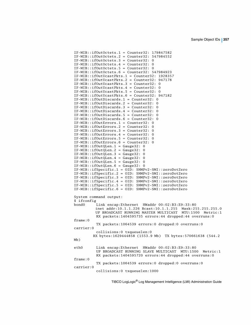
Sample Object IDs | 357
IF-MIB::ifOutOctets.1 = Counter32: 179847582IF-MIB::ifOutOctets.2 = Counter32: 547984552IF-MIB::ifOutOctets.3 = Counter32: 0IF-MIB::ifOutOctets.4 = Counter32: 0IF-MIB::ifOutOctets.5 = Counter32: 0IF-MIB::ifOutOctets.6 = Counter32: 547984923IF-MIB::ifOutUcastPkts.1 = Counter32: 1928357IF-MIB::ifOutUcastPkts.2 = Counter32: 947178IF-MIB::ifOutUcastPkts.3 = Counter32: 0IF-MIB::ifOutUcastPkts.4 = Counter32: 0IF-MIB::ifOutUcastPkts.5 = Counter32: 0IF-MIB::ifOutUcastPkts.6 = Counter32: 947182IF-MIB::ifOutDiscards.1 = Counter32: 0IF-MIB::ifOutDiscards.2 = Counter32: 0IF-MIB::ifOutDiscards.3 = Counter32: 0IF-MIB::ifOutDiscards.4 = Counter32: 0IF-MIB::ifOutDiscards.5 = Counter32: 0IF-MIB::ifOutDiscards.6 = Counter32: 0IF-MIB::ifOutErrors.1 = Counter32: 0IF-MIB::ifOutErrors.2 = Counter32: 0IF-MIB::ifOutErrors.3 = Counter32: 0IF-MIB::ifOutErrors.4 = Counter32: 0IF-MIB::ifOutErrors.5 = Counter32: 0IF-MIB::ifOutErrors.6 = Counter32: 0IF-MIB::ifOutQLen.1 = Gauge32: 0IF-MIB::ifOutQLen.2 = Gauge32: 0IF-MIB::ifOutQLen.3 = Gauge32: 0IF-MIB::ifOutQLen.4 = Gauge32: 0IF-MIB::ifOutQLen.5 = Gauge32: 0IF-MIB::ifOutQLen.6 = Gauge32: 0IF-MIB::ifSpecific.1 = OID: SNMPv2-SMI::zeroDotZeroIF-MIB::ifSpecific.2 = OID: SNMPv2-SMI::zeroDotZeroIF-MIB::ifSpecific.3 = OID: SNMPv2-SMI::zeroDotZeroIF-MIB::ifSpecific.4 = OID: SNMPv2-SMI::zeroDotZeroIF-MIB::ifSpecific.5 = OID: SNMPv2-SMI::zeroDotZeroIF-MIB::ifSpecific.6 = OID: SNMPv2-SMI::zeroDotZero
System command output:$ ifconfigbond0 Link encap:Ethernet HWaddr 00:02:B3:E9:33:80 inet addr:10.1.1.226 Bcast:10.1.1.255 Mask:255.255.255.0 UP BROADCAST RUNNING MASTER MULTICAST MTU:1500 Metric:1 RX packets:1404595735 errors:44 dropped:44 overruns:0 frame:0 TX packets:1064539 errors:0 dropped:0 overruns:0 carrier:0 collisions:0 txqueuelen:0 RX bytes:1629444858 (1553.9 Mb) TX bytes:570661638 (544.2 Mb)
eth0 Link encap:Ethernet HWaddr 00:02:B3:E9:33:80 UP BROADCAST RUNNING SLAVE MULTICAST MTU:1500 Metric:1 RX packets:1404595720 errors:44 dropped:44 overruns:0 frame:0 TX packets:1064539 errors:0 dropped:0 overruns:0 carrier:0 collisions:0 txqueuelen:1000
TIBCO LogLogic® Log Management Intelligence (LMI) Administration Guide

358 | Appendix B SNMP
RX bytes:1629441929 (1553.9 Mb) TX bytes:570661638 (544.2 Mb) Base address:0x8440 Memory:fe020000-fe040000
eth1 Link encap:Ethernet HWaddr 00:02:B3:E9:33:80 UP BROADCAST NOARP SLAVE MULTICAST MTU:1500 Metric:1 RX packets:0 errors:0 dropped:0 overruns:0 frame:0 TX packets:0 errors:0 dropped:0 overruns:0 carrier:0 collisions:0 txqueuelen:1000 RX bytes:0 (0.0 b) TX bytes:0 (0.0 b)
lo Link encap:Local Loopback inet addr:127.0.0.1 Mask:255.0.0.0 UP LOOPBACK RUNNING MTU:16436 Metric:1 RX packets:1947784 errors:0 dropped:0 overruns:0 frame:0 TX packets:1947784 errors:0 dropped:0 overruns:0 carrier:0 collisions:0 txqueuelen:0 RX bytes:181891708 (173.4 Mb) TX bytes:181891708 (173.4 Mb)
$ snmpwalk -v2c 10.1.1.226 -c public 1.3.6.1.4.1.2021.10.1System load averages.UCD-SNMP-MIB::laIndex.1 = INTEGER: 1UCD-SNMP-MIB::laIndex.2 = INTEGER: 2UCD-SNMP-MIB::laIndex.3 = INTEGER: 3UCD-SNMP-MIB::laNames.1 = STRING: Load-1UCD-SNMP-MIB::laNames.2 = STRING: Load-5UCD-SNMP-MIB::laNames.3 = STRING: Load-15UCD-SNMP-MIB::laLoad.1 = STRING: 2.69UCD-SNMP-MIB::laLoad.2 = STRING: 2.61UCD-SNMP-MIB::laLoad.3 = STRING: 2.44UCD-SNMP-MIB::laConfig.1 = STRING: 12.00UCD-SNMP-MIB::laConfig.2 = STRING: 12.00UCD-SNMP-MIB::laConfig.3 = STRING: 12.00UCD-SNMP-MIB::laLoadInt.1 = INTEGER: 268UCD-SNMP-MIB::laLoadInt.2 = INTEGER: 260UCD-SNMP-MIB::laLoadInt.3 = INTEGER: 243UCD-SNMP-MIB::laLoadFloat.1 = Opaque: Float: 2.690000UCD-SNMP-MIB::laLoadFloat.2 = Opaque: Float: 2.610000UCD-SNMP-MIB::laLoadFloat.3 = Opaque: Float: 2.440000UCD-SNMP-MIB::laErrorFlag.1 = INTEGER: 0UCD-SNMP-MIB::laErrorFlag.2 = INTEGER: 0UCD-SNMP-MIB::laErrorFlag.3 = INTEGER: 0UCD-SNMP-MIB::laErrMessage.1 = STRING:UCD-SNMP-MIB::laErrMessage.2 = STRING:UCD-SNMP-MIB::laErrMessage.3 = STRING:
$ snmpwalk -v2c 10.1.1.226 -c public 1.3.6.1.4.1.2021.11CPU usage.snmpwalk -v2c 10.1.1.226 -c public 1.3.6.1.4.1.2021.11UCD-SNMP-MIB::ssIndex.0 = INTEGER: 1UCD-SNMP-MIB::ssErrorName.0 = STRING: systemStatsUCD-SNMP-MIB::ssSwapIn.0 = INTEGER: 2UCD-SNMP-MIB::ssSwapOut.0 = INTEGER: 1UCD-SNMP-MIB::ssIOSent.0 = INTEGER: 34UCD-SNMP-MIB::ssIOReceive.0 = INTEGER: 2
TIBCO LogLogic® Log Management Intelligence (LMI) Administration Guide

Sample Object IDs | 359
UCD-SNMP-MIB::ssSysInterrupts.0 = INTEGER: 2UCD-SNMP-MIB::ssSysContext.0 = INTEGER: 19UCD-SNMP-MIB::ssCpuUser.0 = INTEGER: 13UCD-SNMP-MIB::ssCpuSystem.0 = INTEGER: 22UCD-SNMP-MIB::ssCpuIdle.0 = INTEGER: 63UCD-SNMP-MIB::ssCpuRawUser.0 = Counter32: 7283712UCD-SNMP-MIB::ssCpuRawNice.0 = Counter32: 6917114UCD-SNMP-MIB::ssCpuRawSystem.0 = Counter32: 22873470UCD-SNMP-MIB::ssCpuRawIdle.0 = Counter32: 65327096UCD-SNMP-MIB::ssCpuRawKernel.0 = Counter32: 22873470UCD-SNMP-MIB::ssIORawSent.0 = Counter32: 1529174198UCD-SNMP-MIB::ssIORawReceived.0 = Counter32: 2322564824UCD-SNMP-MIB::ssRawInterrupts.0 = Counter32: 1805767855UCD-SNMP-MIB::ssRawContexts.0 = Counter32: 3197292578UCD-SNMP-MIB::systemStats.62.0 = Counter32: 567530UCD-SNMP-MIB::systemStats.63.0 = Counter32: 349201
System command output:$ vmstat 1 10procs -----------memory---------- ---swap-- -----io---- --system-- ----cpu---- r b swpd free buff cache si so bi bo in cs us sy id wa 1 1 204464 49616 77736 1763564 2 1 34 2 2 19 14 22 64 0 4 2 204464 46388 77744 1764116 0 0 0 30240 7020 11827 7 30 63 0 2 0 204464 49304 77760 1762952 1216 0 1216 10880 6806 10088 8 48 44 0 1 0 204464 49264 77772 1763136 0 0 0 0 6544 11681 6 21 74 0 2 0 204464 45792 77592 1763304 0 0 0 0 6441 11931 8 22 71 0 1 0 204464 48384 77736 1763328 0 0 0 284 6478 8893 8 18 75 0 3 0 204464 48448 77748 1763288 0 0 0 0 6502 11732 6 21 73 0 1 0 204464 48864 77760 1763460 0 0 0 0 6478 11506 7 18 75 0 2 1 204464 49416 77772 1761916 0 0 0 16916 6580 11303 8 19 73 0 1 1 204464 49468 77664 1763008 0 0 0 32784 6675 10961 9 18 73 0
$ snmpwalk -v2c 10.1.1.226 -c public 1.3.6.1.4.1.2021.9Disk stats.UCD-SNMP-MIB::dskIndex.1 = INTEGER: 1UCD-SNMP-MIB::dskIndex.2 = INTEGER: 2UCD-SNMP-MIB::dskIndex.3 = INTEGER: 3UCD-SNMP-MIB::dskIndex.4 = INTEGER: 4UCD-SNMP-MIB::dskPath.1 = STRING: /UCD-SNMP-MIB::dskPath.2 = STRING: /failsafeUCD-SNMP-MIB::dskPath.3 = STRING: /tmpUCD-SNMP-MIB::dskPath.4 = STRING: /loglogicUCD-SNMP-MIB::dskDevice.1 = STRING: /dev/scsi/host0/bus0/target0/lun0/part1
TIBCO LogLogic® Log Management Intelligence (LMI) Administration Guide

360 | Appendix B SNMP
UCD-SNMP-MIB::dskDevice.2 = STRING: /dev/scsi/host0/bus0/target0/lun0/part2UCD-SNMP-MIB::dskDevice.3 = STRING: /dev/scsi/host0/bus0/target0/lun0/part5UCD-SNMP-MIB::dskDevice.4 = STRING: /dev/scsi/host0/bus0/target2/lun0/part1UCD-SNMP-MIB::dskMinimum.1 = INTEGER: 10000UCD-SNMP-MIB::dskMinimum.2 = INTEGER: 10000UCD-SNMP-MIB::dskMinimum.3 = INTEGER: 100000UCD-SNMP-MIB::dskMinimum.4 = INTEGER: 100000UCD-SNMP-MIB::dskMinPercent.1 = INTEGER: -1UCD-SNMP-MIB::dskMinPercent.2 = INTEGER: -1UCD-SNMP-MIB::dskMinPercent.3 = INTEGER: -1UCD-SNMP-MIB::dskMinPercent.4 = INTEGER: -1UCD-SNMP-MIB::dskTotal.1 = INTEGER: 1494236UCD-SNMP-MIB::dskTotal.2 = INTEGER: 1035692UCD-SNMP-MIB::dskTotal.3 = INTEGER: 1035692UCD-SNMP-MIB::dskTotal.4 = INTEGER: 1960866168UCD-SNMP-MIB::dskAvail.1 = INTEGER: 1188804UCD-SNMP-MIB::dskAvail.2 = INTEGER: 554520UCD-SNMP-MIB::dskAvail.3 = INTEGER: 948528UCD-SNMP-MIB::dskAvail.4 = INTEGER: 1552997244UCD-SNMP-MIB::dskUsed.1 = INTEGER: 229528UCD-SNMP-MIB::dskUsed.2 = INTEGER: 428560UCD-SNMP-MIB::dskUsed.3 = INTEGER: 34552UCD-SNMP-MIB::dskUsed.4 = INTEGER: 407868924UCD-SNMP-MIB::dskPercent.1 = INTEGER: 16UCD-SNMP-MIB::dskPercent.2 = INTEGER: 44UCD-SNMP-MIB::dskPercent.3 = INTEGER: 4UCD-SNMP-MIB::dskPercent.4 = INTEGER: 21UCD-SNMP-MIB::dskPercentNode.1 = INTEGER: 4UCD-SNMP-MIB::dskPercentNode.2 = INTEGER: 8UCD-SNMP-MIB::dskPercentNode.3 = INTEGER: 0UCD-SNMP-MIB::dskPercentNode.4 = INTEGER: 0UCD-SNMP-MIB::dskErrorFlag.1 = INTEGER: 0UCD-SNMP-MIB::dskErrorFlag.2 = INTEGER: 0UCD-SNMP-MIB::dskErrorFlag.3 = INTEGER: 0UCD-SNMP-MIB::dskErrorFlag.4 = INTEGER: 0UCD-SNMP-MIB::dskErrorMsg.1 = STRING:UCD-SNMP-MIB::dskErrorMsg.2 = STRING:UCD-SNMP-MIB::dskErrorMsg.3 = STRING:UCD-SNMP-MIB::dskErrorMsg.4 = STRING:
System command output:$ dfFilesystem 1K-blocks Used Available Use% Mounted on/dev/scsi/host0/bus0/target0/lun0/part1 1494236 229536 1188796 17% //dev/scsi/host0/bus0/target0/lun0/part2 1035692 428560 554520 44% /failsafe/dev/scsi/host0/bus0/target0/lun0/part5 1035692 34552 948528 4% /tmp/dev/scsi/host0/bus0/target2/lun0/part1 1960866168 407891296 1552974872 21% /loglogic
$ snmpwalk -v2c 10.1.1.226 -c public 1.3.6.1.4.1.2021.4Memory stats.
TIBCO LogLogic® Log Management Intelligence (LMI) Administration Guide

Sample Object IDs | 361
UCD-SNMP-MIB::memIndex.0 = INTEGER: 0UCD-SNMP-MIB::memErrorName.0 = STRING: swapUCD-SNMP-MIB::memTotalSwap.0 = INTEGER: 1052248UCD-SNMP-MIB::memAvailSwap.0 = INTEGER: 847824UCD-SNMP-MIB::memTotalReal.0 = INTEGER: 2067508UCD-SNMP-MIB::memAvailReal.0 = INTEGER: 49424UCD-SNMP-MIB::memTotalFree.0 = INTEGER: 897252UCD-SNMP-MIB::memMinimumSwap.0 = INTEGER: 16000UCD-SNMP-MIB::memShared.0 = INTEGER: 0UCD-SNMP-MIB::memBuffer.0 = INTEGER: 79240UCD-SNMP-MIB::memCached.0 = INTEGER: 1765480UCD-SNMP-MIB::memSwapError.0 = INTEGER: 0UCD-SNMP-MIB::memSwapErrorMsg.0 = STRING:
System command output:$ free total used free shared buffers cachedMem: 2067508 1937788 129720 0 79360 1680940-/+ buffers/cache: 177488 1890020Swap: 1052248 204424 847824
IPv6 Examples
The following IPv6 examples show a few query and response details on an Appliance with a sample IP address of fd00::aaaa:a72:4a2b and community string public. $snmpwalk -v2c udp6:[fd00::aaaa:a72:4a2b]:161 -c public .1.3.6.1.2.1.1.3.0
TIBCO LogLogic® Log Management Intelligence (LMI) Administration Guide

362 | Appendix B SNMP
Supported Object IDs
There are several other supported Object IDs (OID) on LogLogic Appliances. To view them, access them from top node 1 or provide the OID explicitly to access data. You can also contact [email protected] if you cannot find a particular OID.
For every symbolic name, there are two OIDs: one for LX or MX, and one for ST.
Table 25 Supported OIDs
Object ID (OID) Symbolic Name Definitions
For LX or MX OID: SNMPv2-SMI::enterprises.18552.1.2.1.10
For ST OID: SNMPv2-SMI::enterprises.18552.2.2.1.10
macAddr System etho interface media access control address
For LX or MX OID:SNMPv2-SMI::enterprises.18552.1.2.1.11
For ST OID:SNMPv2-SMI::enterprises.18552.2.2.1.11
productSelected Name of the LogLogic Appliance product family (ST, LX, or MX).
For LX or MX OID: SNMPv2-SMI::enterprises.18552.1.2.1.12
For ST OID: SNMPv2-SMI::enterprises.18552.2.2.1.12
modelSelected Model of the Appliance.
For LX or MX OID: SNMPv2-SMI::enterprises.18552.1.2.1.13
For ST OID: SNMPv2-SMI::enterprises.18552.2.2.1.13
messageQueueInserts
Slot number that the most recent message was placed. This number indicate that the Appliance received this many number of messages so far from boot time.
For LX or MX OID: SNMPv2-SMI::enterprises.18552.1.2.1.14
For ST OID: SNMPv2-SMI::enterprises.18552.2.2.1.14
messageQueueReads
Slot number that the parser refers to read next message from the received message queue.
TIBCO LogLogic® Log Management Intelligence (LMI) Administration Guide

Supported Object IDs | 363
For LX or MX OID: SNMPv2-SMI::enterprises.18552.1.2.1.15
For ST OID: SNMPv2-SMI::enterprises.18552.2.2.1.15
messageDrops Number of messages that were dropped. This number indicate that the Appliance is loosing messages because of the lack of resources.
For LX or MX OID: SNMPv2-SMI::enterprises.18552.1.2.1.16
For ST OID: SNMPv2-SMI::enterprises.18552.2.2.1.16
msgRatePerMin Number of messages received during the last minute.
For LX or MX OID: SNMPv2-SMI::enterprises.18552.1.2.1.17
For ST OID: SNMPv2-SMI::enterprises.18552.2.2.1.17
msgRatePer5Min Number of messages received during the last five minutes.
For LX or MX OID: SNMPv2-SMI::enterprises.18552.1.2.1.18
For ST OID: SNMPv2-SMI::enterprises.18552.2.2.1.18
msgRatePer15Min Number of messages received during the last fifteen minutes.
For LX or MX OID: SNMPv2-SMI::enterprises.18552.1.2.1.19
For ST OID: SNMPv2-SMI::enterprises.18552.2.2.1.19
totalSyslogSources
Number of syslog log sources that the Appliance is receiving messages from.
For LX or MX OID: SNMPv2-SMI::enterprises.18552.1.2.1.20
For ST OID: SNMPv2-SMI::enterprises.18552.2.2.1.20
totalSyslogReceivers
Total number of active syslog receivers in the list.
Table 25 Supported OIDs (Cont’d)
Object ID (OID) Symbolic Name Definitions
TIBCO LogLogic® Log Management Intelligence (LMI) Administration Guide

364 | Appendix B SNMP
For LX or MX OID: SNMPv2-SMI::enterprises.18552.1.2.1.21
For ST OID: SNMPv2-SMI::enterprises.18552.2.2.1.21
totalTrapReceivers
Appliance is able to receive and forward SNMP traps. This is a counter that represents the total number of trap senders to the Appliance.
For LX or MX OID: SNMPv2-SMI::enterprises.18552.1.2.1.22
For ST OID: SNMPv2-SMI::enterprises.18552.2.2.1.22
totalLEAServers Total number of Check Point LEA servers.
For LX or MX OID: SNMPv2-SMI::enterprises.18552.1.2.1.23
For ST OID: SNMPv2-SMI::enterprises.18552.2.2.1.23
startLEAAgent ID of the LEA agent to start.
For LX or MX OID: SNMPv2-SMI::enterprises.18552.1.2.1.24
For ST OID: SNMPv2-SMI::enterprises.18552.2.2.1.24
totalUsers Total number of users on the Appliance.
For LX or MX OID: SNMPv2-SMI::enterprises.18552.1.2.1.25
For ST OID: SNMPv2-SMI::enterprises.18552.2.2.1.25
totalSyslogMessages
Number of log messages received by the Appliance from the last boot.
For LX or MX OID: SNMPv2-SMI::enterprises.18552.1.2.1.26
For ST OID: SNMPv2-SMI::enterprises.18552.2.2.1.26
totalLEAMessages Number of log messages received through LEA server but deprecated in 32.
Table 25 Supported OIDs (Cont’d)
Object ID (OID) Symbolic Name Definitions
TIBCO LogLogic® Log Management Intelligence (LMI) Administration Guide

Supported Object IDs | 365
For LX or MX OID: SNMPv2-SMI::enterprises.18552.1.2.1.27
For ST OID: SNMPv2-SMI::enterprises.18552.2.2.1.27
totalProcessedMessages
Total of all the processed syslog message counters.
For LX or MX OID: SNMPv2-SMI::enterprises.18552.1.2.1.28
For ST OID: SNMPv2-SMI::enterprises.18552.2.2.1.28
totalUnapprovedLEAMessages
Number of log messages received through LEA server but not approved bur deprecated in 3.2 version
For LX or MX OID: SNMPv2-SMI::enterprises.18552.1.2.1.29
For ST OID: SNMPv2-SMI::enterprises.18552.2.2.1.29
totalUnknownSyslogMessages
Total number of messages that are not recognized by the Appliance.
For LX or MX OID: SNMPv2-SMI::enterprises.18552.1.2.1.30
For ST OID: SNMPv2-SMI::enterprises.18552.2.2.1.30
totalOtherSyslogMessages
Total messages difference between total messages received by the Appliance minus all known and unknown messages.
For LX or MX OID: SNMPv2-SMI::enterprises.18552.1.2.1.31
For ST OID: SNMPv2-SMI::enterprises.18552.2.2.1.31
totalSkippedSyslogMessages
Total number of skipped syslog messages. Some messages needs to be skipped not to count twice such as SNMP trap messages or device may be disabled.
For LX or MX OID: SNMPv2-SMI::enterprises.18552.1.2.1.32
For ST OID: SNMPv2-SMI::enterprises.18552.2.2.1.32
totalApprovedSyslogMessages
Total number of approved messages. The message is approved if the used enable the device or auto discover is turned on. Deprecated in LogLogic Release 3.2.
Table 25 Supported OIDs (Cont’d)
Object ID (OID) Symbolic Name Definitions
TIBCO LogLogic® Log Management Intelligence (LMI) Administration Guide

366 | Appendix B SNMP
For LX or MX OID: SNMPv2-SMI::enterprises.18552.1.2.1.33
For ST OID: SNMPv2-SMI::enterprises.18552.2.2.1.33
totalUnapprovedSyslogMessages
Messages come into the Appliance and counted under un approved as long as the corresponding device is in the approved list.
For LX or MX OID: SNMPv2-SMI::enterprises.18552.1.2.1.34
For ST OID: SNMPv2-SMI::enterprises.18552.2.2.1.34
totalAcceptedSyslogMessages
Total number of messages accepted by the Appliance in firewall category.
For LX or MX OID: SNMPv2-SMI::enterprises.18552.1.2.1.35
For ST OID: SNMPv2-SMI::enterprises.18552.2.2.1.35
totalDeniedSyslogMessages
Total number of messages denied by the Appliance in firewall category.
For LX or MX OID: SNMPv2-SMI::enterprises.18552.1.2.1.36
For ST OID: SNMPv2-SMI::enterprises.18552.2.2.1.36
totalSecuritySyslogMessages
Total number of messages categorized as firewall security messages received.
For LX or MX OID: SNMPv2-SMI::enterprises.18552.1.2.1.37
For ST OID: SNMPv2-SMI::enterprises.18552.2.2.1.37
totalSystemSyslogMessages
Total number of syslog messages received by the Appliance in firewall category.
For LX or MX OID: SNMPv2-SMI::enterprises.18552.1.2.1.38
For ST OID: SNMPv2-SMI::enterprises.18552.2.2.1.38
totalFTPSyslogMessages
Number of messages received through FTP protocol in firewall category.
Table 25 Supported OIDs (Cont’d)
Object ID (OID) Symbolic Name Definitions
TIBCO LogLogic® Log Management Intelligence (LMI) Administration Guide
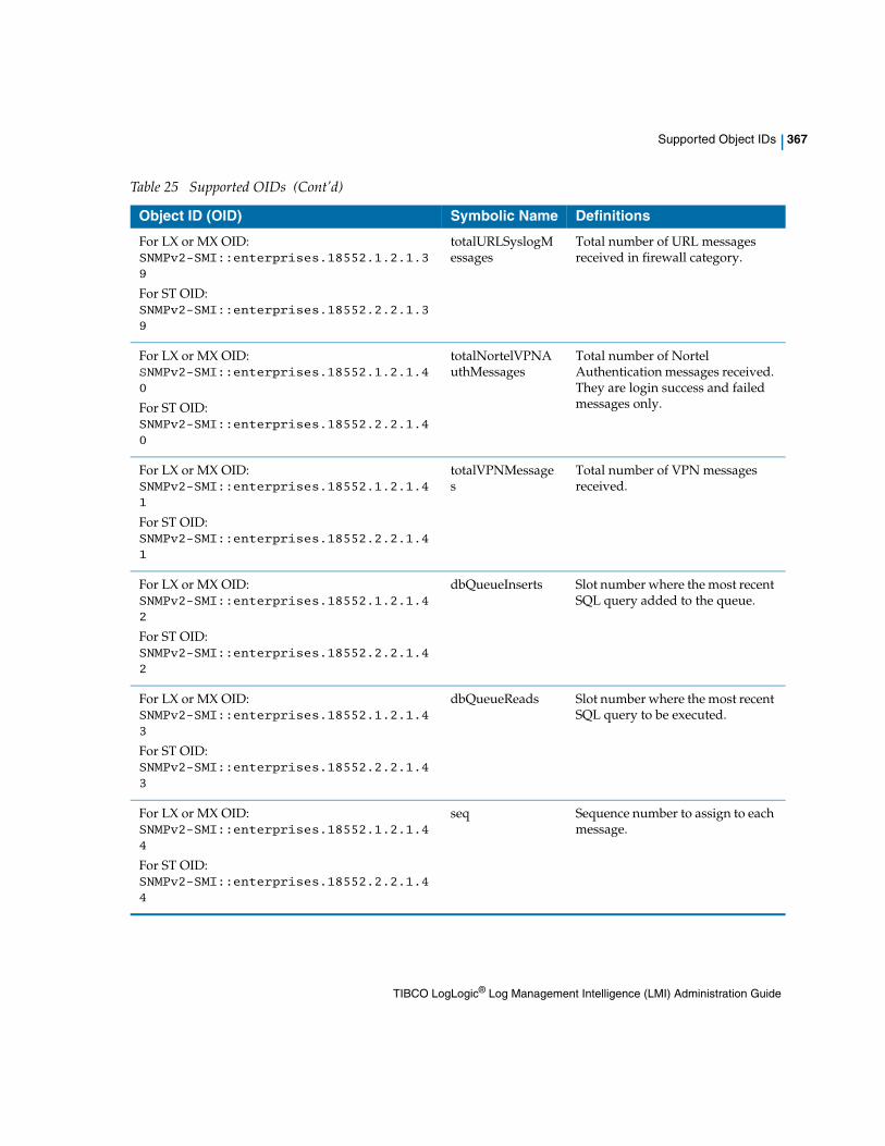
Supported Object IDs | 367
For LX or MX OID: SNMPv2-SMI::enterprises.18552.1.2.1.39
For ST OID: SNMPv2-SMI::enterprises.18552.2.2.1.39
totalURLSyslogMessages
Total number of URL messages received in firewall category.
For LX or MX OID: SNMPv2-SMI::enterprises.18552.1.2.1.40
For ST OID: SNMPv2-SMI::enterprises.18552.2.2.1.40
totalNortelVPNAuthMessages
Total number of Nortel Authentication messages received. They are login success and failed messages only.
For LX or MX OID: SNMPv2-SMI::enterprises.18552.1.2.1.41
For ST OID: SNMPv2-SMI::enterprises.18552.2.2.1.41
totalVPNMessages
Total number of VPN messages received.
For LX or MX OID: SNMPv2-SMI::enterprises.18552.1.2.1.42
For ST OID: SNMPv2-SMI::enterprises.18552.2.2.1.42
dbQueueInserts Slot number where the most recent SQL query added to the queue.
For LX or MX OID: SNMPv2-SMI::enterprises.18552.1.2.1.43
For ST OID: SNMPv2-SMI::enterprises.18552.2.2.1.43
dbQueueReads Slot number where the most recent SQL query to be executed.
For LX or MX OID: SNMPv2-SMI::enterprises.18552.1.2.1.44
For ST OID: SNMPv2-SMI::enterprises.18552.2.2.1.44
seq Sequence number to assign to each message.
Table 25 Supported OIDs (Cont’d)
Object ID (OID) Symbolic Name Definitions
TIBCO LogLogic® Log Management Intelligence (LMI) Administration Guide

368 | Appendix B SNMP
For LX or MX OID: SNMPv2-SMI::enterprises.18552.1.2.1.45
For ST OID: SNMPv2-SMI::enterprises.18552.2.2.1.45
rsenderQueueInUse
Spin lock semaphore flag for rsender queue.
For LX or MX OID: SNMPv2-SMI::enterprises.18552.1.2.1.46
For ST OID: SNMPv2-SMI::enterprises.18552.2.2.1.46
rsenderQueueInserts
Slot number for the next message to be inserted for rsender.
For LX or MX OID: SNMPv2-SMI::enterprises.18552.1.2.1.47
For ST OID: SNMPv2-SMI::enterprises.18552.2.2.1.47
rsenderQueueReads
Slot number from which the next message to be read by rsender.
For LX or MX OID: SNMPv2-SMI::enterprises.18552.1.2.1.48
For ST OID: SNMPv2-SMI::enterprises.18552.2.2.1.48
rsenderDrops Number of message that were dropped by rsender.
For LX or MX OID: SNMPv2-SMI::enterprises.18552.1.2.1.49
For ST OID: SNMPv2-SMI::enterprises.18552.2.2.1.49
startTime Time when the engines shared memory segment was created.
For LX or MX OID: SNMPv2-SMI::enterprises.18552.1.2.1.50
For ST OID: SNMPv2-SMI::enterprises.18552.2.2.1.50
messageTooLong Number of messages that were unable to fit into buffer slot.
Table 25 Supported OIDs (Cont’d)
Object ID (OID) Symbolic Name Definitions
TIBCO LogLogic® Log Management Intelligence (LMI) Administration Guide

Supported Object IDs | 369
For LX or MX OID: SNMPv2-SMI::enterprises.18552.1.2.1.51
For ST OID: SNMPv2-SMI::enterprises.18552.2.2.1.51
msgRatePerSec Number of messages received during the last second.
For LX or MX OID: SNMPv2-SMI::enterprises.18552.1.2.1.60
For ST OID: SNMPv2-SMI::enterprises.18552.2.2.1.60
CPUFanSpeed Variable set for a group of data. Each group is in sensor number, fan speed RPM, high threshold, and low threshold form.
For LX or MX OID: SNMPv2-SMI::enterprises.18552.1.2.1.61
For ST OID: SNMPv2-SMI::enterprises.18552.2.2.1.61
SysFanSpeed Variable set for a group of data. Each group is in sensor number, fan speed RPM, high threshold, and low threshold form.
For LX or MX OID: SNMPv2-SMI::enterprises.18552.1.2.1.62
For ST OID: SNMPv2-SMI::enterprises.18552.2.2.1.62
CPUTemperature Variable set for a group of data. Each group is in sensor number, Celsius degrees, high threshold, and low threshold form.
Table 25 Supported OIDs (Cont’d)
Object ID (OID) Symbolic Name Definitions
TIBCO LogLogic® Log Management Intelligence (LMI) Administration Guide

370 | Appendix B SNMP
Available Traps
An SNMP trap is an asynchronous event-generated message that an Appliance sends to its client. The client is a trap receiver which is normally a network monitoring station. The LogLogic Appliance supports a set of SNMP traps sent to alert a user.
For SNMP version 1, use the ESTN in Table 26.
Table 26 Categories of Alerts Available as SNMP Traps running version 1
Alert Category Alert Name Enterprise-OID ESTN Description
Cisco PIX Messages Alert
Cisco PIX Messages Alert
ent.18552.1.3
ent.18552.2.3 (ST)
1 The messages per second rate for a specific PIX message code is outside (above or below) specified rates
Network Policy Alert
Network Policy Alert
ent.18552.1.3
ent.18552.2.3 (ST)
92 A network policy messages was received with an Accept or Deny Policy action
Adaptive Baseline Alert
Adaptive Baseline Alert
ent.18552.1.3
ent.18552.2.3 (ST)
93 The messages per second rate is outside (above or below) the nominal traffic rate
Ratio Based Alert
Ratio Based Alert
ent.18552.1.3
ent.18552.2.3 (ST)
94 The specified message count is outside a specified percentage of total messages
VPN Statistics Alert
VPN Statistics Alert
ent.18552.1.3
ent.18552.2.3 (ST)
95 Recorded statistics on VPN or RADIUS messages match relative or absolute criteria
VPN Connections Alert
VPN Connections Alert
ent.18552.1.3
ent.18552.2.3 (ST)
96 A VPN Disconnects or Deny event occurred
VPN Messages Alert
VPN Messages Alert
ent.18552.1.3
ent.18552.2.3 (ST)
97 A VPN Message Alert triggered on combinations of specific VPN message area, severity, and code
TIBCO LogLogic® Log Management Intelligence (LMI) Administration Guide

Available Traps | 371
If you are using SNMP version 2, the TrapOID differs for each trap. Table 27 lists the TrapOID for each alert category.
Message Volume Alert
Message Volume Alert
ent.18552.1.3
ent.18552.2.3 (ST)
98 The messages per second rate is outside (above or below) specified limits. If the user sets the “Zero Message Alert” checkbox, an alert is triggered only if zero messages are received within the timespan set.
Pre-defined Search Filter
Pre-defined Search Filter Alert
ent.18552.1.3
ent.18552.2.3 (ST)
99 A text search filter matched message fields
System Alert Dropped- message
ent.18552.1.3
ent.18552.2.3 (ST)
189 Dropped messages exceeded the user-specified limit
Failover ent.18552.1.3
ent.18552.2.3 (ST)
191 A failover occurred
Disk Usage ent.18552.1.3
ent.18552.2.3 (ST)
192 Disk usage exceeded the specified threshold
Network Connection Speed
ent.18552.1.3
ent.18552.2.3 (ST)
193 Network connection throughput fell below the specified threshold
Network Interface
ent.18552.1.3
ent.18552.2.3 (ST)
194 The configured network interface failed
Data Migration ent.18552.1.3
ent.18552.2.3 (ST)
195 A data migration completed
CPU temperature
ent.18552.1.3
ent.18552.2.3 (ST)
197 The CPU temperature exceeded the specified limit
Synchronization Failure
ent.18552.1.3
ent.18552.2.3 (ST)
198 Data synchronization failed after a failover
Secure Tunnel connection status
ent.18552.1.3
ent.18552.2.3 (ST)
199 The configured TCP forward connection failed
Table 26 Categories of Alerts Available as SNMP Traps running version 1 (Cont’d)
Alert Category Alert Name Enterprise-OID ESTN Description
TIBCO LogLogic® Log Management Intelligence (LMI) Administration Guide

372 | Appendix B SNMP
The TIBCO LogLogic Appliance uses SNMP v1 by default. In order to use v2c the admin needs to edit the following file:
Logapp root:~$ cat /loglogic/conf/snmpd_alerts_trap_version
version: 1 type: snmptrap
Logapp root:~$
Update the version from 1 to 2 in the file.
If this file does not exist, create the file with:version: 1 type: snmptrap
The file can then be edited to version 2 if required.
Table 27 Categories of Alerts Available as SNMP Traps running version 2
Alert Category Alert Name TrapOID Description
Cisco PIX Messages Alert
Cisco PIX Messages Alert
ent.18552.1.3.3
ent.18552.2.3.3 (ST)
The messages per second rate for a specific PIX message code is outside (above or below) specified rates
Network Policy Alert
Network Policy Alert
ent.18552.1.3.92
ent.18552.2.3.92 (ST)
A network policy messages was received with an Accept or Deny Policy action
Adaptive Baseline Alert
Adaptive Baseline Alert
ent.18552.1.3.93
ent.18552.2.3.93 (ST)
The messages per second rate is outside (above or below) the nominal traffic rate
Ratio Based Alert Ratio Based Alert ent.18552.1.3.94
ent.18552.2.3.94 (ST)
The specified message count is outside a specified percentage of total messages
VPN Statistics Alert
VPN Statistics Alert
ent.18552.1.3.95
ent.18552.2.3.95 (ST)
Recorded statistics on VPN or RADIUS messages match relative or absolute criteria
VPN Connections Alert
VPN Connections Alert
ent.18552.1.3.96
ent.18552.2.3.96 (ST)
A VPN Disconnects or Deny event occurred
VPN Messages Alert
VPN Messages Alert
ent.18552.1.3.97
ent.18552.2.3.97 (ST)
A VPN Message Alert triggered on combinations of specific VPN message area, severity, and code
TIBCO LogLogic® Log Management Intelligence (LMI) Administration Guide

Available Traps | 373
Message Volume Alert
Message Volume Alert
ent.18552.1.3.98
ent.18552.2.3.98 (ST)
The messages per second rate is outside (above or below) specified limits. If the user sets the “Zero Message Alert” checkbox, an alert is triggered only if zero messages are received within the timespan set.
Pre-defined Search Filter
Pre-defined Search Filter Alert
ent.18552.1.3.99
ent.18552.2.3.99 (ST)
A text search filter matched message fields
System Alert Dropped-message ent.18552.1.3.189
ent.18552.2.3.189 (ST)
Dropped messages exceeded the user-specified limit
Failover ent.18552.1.3.191
ent.18552.2.3.191 (ST)
A failover occurred
Disk Usage ent.18552.1.3.192
ent.18552.2.3.192 (ST)
Disk usage exceeded the specified threshold
Network Connection Speed
ent.18552.1.3.193
ent.18552.2.3.193 (ST)
Network connection throughput fell below the specified threshold
Network Interface ent.18552.1.3.194
ent.18552.2.3.194 (ST)
The configured network interface failed
Data Migration ent.18552.1.3.195
ent.18552.2.3.195 (ST)
A data migration completed
CPU temperature ent.18552.1.3.197
ent.18552.2.3.197 (ST)
The CPU temperature exceeded the specified limit
Synchronization Failure
ent.18552.1.3.198
ent.18552.2.3.198 (ST)
Data synchronization failed after a failover
Table 27 Categories of Alerts Available as SNMP Traps running version 2 (Cont’d)
Alert Category Alert Name TrapOID Description
TIBCO LogLogic® Log Management Intelligence (LMI) Administration Guide

374 | Appendix B SNMP
Other TrapsBesides the LogLogic application-specific traps, the SNMP agent running on your Appliance also sends the following traps:
• SNMPv2-MIB::coldStart
• SNMPv2-MIB::authenticationFailure
• NET-SNMP-AGENT-MIB::nsNotifyShutdown • NET-SNMP-AGENT-MIB::nsNotifyRestart
These traps, and the sample messages below, are normal messages received in the specified situations.
Sample Messages Received at a Receiver
When a system where SNMP is enabled starts up:
2005-08-12 00:57:24 10.1.1.226 [10.1.1.226]:
SNMPv2-MIB::sysUpTime.0 = Timeticks: (9) 0:00:00.09 SNMPv2-MIB::snmpTrapOID.0 = OID: SNMPv2-MIB::coldStart SNMPv2-MIB::snmpTrapEnterprise.0 = OID: NET-SNMP-MIB::netSnmpAgentOIDs.10
When a system where SNMP is enabled stops:
2005-08-12 00:57:21 10.1.1.226 [10.1.1.226]:
NMPv2-MIB::snmpTrapEnterprise.0 = OID: NET-SNMP-MIB::netSnmpAgentOIDs.10 2005-08-12 00:57:21 10.1.1.226 [10.1.1.226]:SNMPv2-MIB::sysUpTime.0 = Timeticks: (2938) 0:00:29.38 SNMPv2-MIB::snmpTrapOID.0 = OID: NET-SNMP-AGENT-MIB::nsNotifyShutdown
When the agent receives a SIGHUP signal:
2005-08-12 00:59:49 10.1.1.226 [10.1.1.226]:
SNMPv2-MIB::sysUpTime.0 = Timeticks: (14462) 0:02:24.62 SNMPv2-MIB::snmpTrapOID.0 = OID: NET-SNMP-AGENT-MIB::nsNotifyRestart
When the agent receives a request using an unknown community name:
Secure Tunnel connection status
ent.18552.1.3.199
ent.18552.2.3.199 (ST)
The configured TCP forward connection failed
Table 27 Categories of Alerts Available as SNMP Traps running version 2 (Cont’d)
Alert Category Alert Name TrapOID Description
TIBCO LogLogic® Log Management Intelligence (LMI) Administration Guide

Available Traps | 375
SNMPv2-MIB::sysUpTime.0 = Timeticks: (147115816) 17 SNMPv2-MIB::snmpTrapOID.0 = OID: SNMPv2-MIB::authenticationFailureSNMPv2-MIB::snmpTrapEnterprise.0 = OID: NET-SNMP-MIB::netSnmpAgentOIDs.10
LX or MX Trap AttributesThe alerts on LX or MX Appliances generate SNMP traps with these VarBind parameters:
{lxTrapDesc, lxLocalAddress, lxTime, lxTrapSourceIP, lxUserOid, lxTrapMsg}
The community string for these trap attributes is public.
ST Trap AttributesThe alerts on ST Appliances generate SNMP traps with the following VarBind parameters:
{stTrapDesc, stLocalAddress, stTime, stTrapSourceIP, stUserOid, stTrapMsg}
The community string for these trap attributes is public.
Table 28 LX or MX Trap Attribute Parameter OID Descriptions
Parameter OID Description
lxTrapDesc OID: SNMPv2-SMI::enterprises.18552.1.2.1.3
lxLocalAddress OID: SNMPv2-SMI::enterprises.18552.1.2.1.4
lxTime OID: SNMPv2-SMI::enterprises.18552.1.2.1.5
lxTrapSourceIP OID: SNMPv2-SMI::enterprises.18552.1.2.1.6
lxUserOid OID: SNMPv2-SMI::enterprises.18552.1.2.1.7
lxTrapMsg OID: SNMPv2-SMI::enterprises.18552.1.2.1.8
Table 29 ST Trap Attribute Parameter OID Descriptions
Parameter OID Description
stTrapDesc OID: SNMPv2-SMI::enterprises.18552.2.2.1.3
stLocalAddress OID: SNMPv2-SMI::enterprises.18552.2.2.1.4
stTime OID: SNMPv2-SMI::enterprises.18552.2.2.1.5
TIBCO LogLogic® Log Management Intelligence (LMI) Administration Guide

376 | Appendix B SNMP
Alert Message Samples
The following are alert message samples. The log message print format is specific to the trap receiver. You can change these according to your production environment.
SNMP version: 1
2008-06-19 19:13:01 10.0.30.33(via UDP: [172.16.0.1]:50326) TRAP, SNMP v1, community public
SNMPv2-SMI::enterprises.18552.1.3 Enterprise Specific Trap (98) Uptime: 21
SNMPv2-SMI::enterprises.18552.1.2.1.3 = STRING: "(Description) "SNMPv2-SMI::enterprises.18552.1.2.1.4 = IpAddress: 10.0.30.33SNMPv2-SMI::enterprises.18552.1.2.1.5 = Timeticks: (1213927981) 140SNMPv2-SMI::enterprises.18552.1.2.1.6 = STRING: "10.0.30.61,10.2.1.13,10.0.30.33,10.2.1.14,10.0.0.11,10.0.30.33,10.0.30.19,10.0.30.34,10.0.30.61,10.2.1.10,10.2.1.9,10.2.1.12,20.11.2.211,20.11.1.211,20.11.4.211,20.11.8.211,20.11.10.211,20.11.7.211,20.11.11.211,20.11.5.211,20.11.9.211,20.11.14.211,20.11.15.211,20.11.16.211,20.11.17.211,20.11.18.211,20.11.13.211,20.11.12.211,20.11.20.211,20.11.19.211,20.11.21.211,20.11.24.211,20.11.25.211,20.11.22.211,20.11.23.211,20.11.26.211,20.11.27.211,20.11.28.211,20.11.29.211,20.11.30.211" SNMPv2-SMI::enterprises.18552.1.2.1.7 = OID: SNMPv2-SMI::enterprises.18552SNMPv2-SMI::enterprises.18552.1.2.1.8 = STRING: "Optional Text;High-ABS-MESSAGE-VOLUME;volume alert1;msgrate:2833;highthresh:110;source: 0.0.0.0"
SNMP version: 2
2008-06-19 18:37:25 NET-SNMP version 5.2.1 Started.
2008-06-19 18:37:56 172.16.0.1 [UDP: [172.16.0.1]:50276]:
SNMPv2-MIB::sysUpTime.0 = Timeticks: (1818885) 5:0SNMPv2-MIB::snmpTrapOID.0 = OID: SNMPv2-SMI::enterprises.18552.1.3.0.98SNMPv2-SMI::enterprises.18552.1.2.1.3 = STRING: "(Description) "SNMPv2-SMI::enterprises.18552.1.2.1.4 = IpAddress: 10.0.30.33SNMPv2-SMI::enterprises.18552.1.2.1.5 = Timeticks: (1213925876) 140SNMPv2-SMI::enterprises.18552.1.2.1.6 = STRING: "10.0.30.61,10.2.1.13,10.0.30.33,10.2.1.14,10.0.0.11,10.0.30.33,10.0.30.19,10.0.30.34,10.0.30.61,10.2.1.10,10.2.1.9,10.2.1.12,20.11.
stTrapSourceIP OID: SNMPv2-SMI::enterprises.18552.2.2.1.6
stUserOid OID: SNMPv2-SMI::enterprises.18552.2.2.1.7
stTrapMsg OID: SNMPv2-SMI::enterprises.18552.2.2.1.8
Table 29 ST Trap Attribute Parameter OID Descriptions (Cont’d)
Parameter OID Description
TIBCO LogLogic® Log Management Intelligence (LMI) Administration Guide

Available Traps | 377
2.211,20.11.1.211,20.11.4.211,20.11.8.211,20.11.10.211,20.11.7.211,20.11.11.211,20.11.5.211,20.11.9.211,20.11.14.211,20.11.15.211,20.11.16.211,20.11.17.211,20.11.18.211,20.11.13.211,20.11.12.211,20.11.20.211,20.11.19.211,20.11.21.211,20.11.24.211,20.11.25.211,20.11.22.211,20.11.23.211,20.11.26.211,20.11.27.211,20.11.28.211,20.11.29.211,20.11.30.211" SNMPv2-SMI::enterprises.18552.1.2.1.7 = OID: SNMPv2-SMI::enterprises.18552SNMPv2-SMI::enterprises.18552.1.2.1.8 = STRING: "Optional Text;High-ABS-MESSAGE-VOLUME;volume alert1;msgrate:3254;highthresh:110;source: 0.0.0.0"
TIBCO LogLogic® Log Management Intelligence (LMI) Administration Guide

378 | Appendix B SNMP
TIBCO LogLogic® Log Management Intelligence (LMI) Administration Guide

| 379
Appendix C Configuration Rule File Definition
The formatted forwarding feature is used to format log messages prior to forwarding. The Forwarding function uses the configuration file that defines the formatting rules. All log messages that match the forwarding rule are formatted.
Rules consist of Regular expressions that are applied to the log messages. If log messages are matched with the Regular expression, then the extracted strings are substituted into the forwarded message before forwarding to the defined destination.
You can upload only one configuration file for each Message Routing rule. Each configuration rule file can be used across multiple destinations or rules, and can have a maximum file size of 1 GB.
Topics
• About Configuration Rule File on page 380
• Configuration Rule File Options on page 382
• Examples of Configuration Rules on page 383
• Define Configuration Rule File on page 385
TIBCO LogLogic® Log Management Intelligence (LMI) Administration Guide

380 | Appendix C Configuration Rule File Definition
About Configuration Rule File
The configuration rule file is used for:
• filtering logs
• transforming/formatting log messages
• filtering character patterns from a log (shredding) and, optionally, replacing them with literal strings
A configuration rule file can consist of multiple rules. A rule consist of either regexp/template pattern or shread/replace pattern.
A regexp/template rule consists of two lines; a Regular expression used to match and extract patterns and the forwarded message template. A shred/replace pattern rule defines shread= option. You can also have both types of rules in the same configuration rule file.
First, regexp/template rules are applied in the order of their appearance in the configuration file. The system will stop applying rules as soon as the first match is detected. The shred/replace rules are applied after a single scan across all regexp/template rules. Only those log messages that match any regexp rule will be forwarded. However, if you use forwardall option, any log message will be forwarded even without matching any regexp rule.
The configuration rule file must satisfy the following criteria:
• rule file cannot be empty
• must consist of one or more rules; either regexp/template rule or shread/replace rule or both types can be in the same rule file
• regexp <regular expression> must be valid; cannot be empty
regexp is a keyword followed by a PCRE-compatible regular expression. A regexp has to succeed in order for a log message to be modified.
For example,regexp(.+)\s(.+)\slx_scheduler:\s(.+)\s(.+):\s\((.+)\)\slx_scheduler:\sending\sconfig\smgmt\sjob
• template must be valid; cannot be empty
The rule has to specify a template for the contents of the forwarded log. The template can contain literal strings as well as portions of the original message. The template is applied to create a new message. After template-driven
It is good practice not to end the regular expression with a capturing pattern (.+), since it will affect performance when capturing a large portion of the message.
TIBCO LogLogic® Log Management Intelligence (LMI) Administration Guide

About Configuration Rule File | 381
formatting is completed, the new log message will be forwarded to the destination of the forwarding rule. $1, $2, etc. in the template refer to the patterns extracted by regexp. Extracted patterns are defined by a matching pair of parentheses, for example (.+) in the above regular expression example. $1 refers to the first pair of parentheses.
It is good practice to use up to $10 matching patterns in the template. You can use the matching patterns repeatedly, however, the digits after the $ sign should be 10 or less than 10.
For example,
template LOGS|LogLogic MODEL|CC01|Application configuration change|5|deviceExternalId=62968-1 msg=ending config mgmt job shost=$2 dhost=$2 suser=system suid=system spriv=User
• shred/replace option (Optional)
Shred option removes the portion of the transformed message based on the template and replaces with the new string, and then forwards the message to the destination.
For example,shred=\d{16} replace=XYZ-XYZ-XYZ-XYZ
shred= regular expression is applied to every message repeatedly in order to identify a sensitive pattern. The sensitive pattern can have more than one instance in the message, all instances will be detected. The shred in the config file must be all in lower-case letters.
replace= optionally defines a substitution string that replaces sensitive string.
TIBCO LogLogic® Log Management Intelligence (LMI) Administration Guide

382 | Appendix C Configuration Rule File Definition
Configuration Rule File Options
It is good practice to add additional options (such as, source_type, match) in the configuration rule file, that will help filter log messages faster and speed up the performance.
If the rule file includes these options, the following criteria must be satisfied:
• source-type must have a valid log type; cannot be empty
source_type= is used to limit regexp filters to logs of specific source type.
For example, source_type=LogLogic Appliance
• Match pattern must be valid; cannot be empty
match= <unique string matching part of the log message>
The “match” can be used and validated only when written as “match=”. If you use “match” only (without =), then it will not be validated.
This will apply the matching string to each log. Only those logs containing the string will be tested against the regular expression. The match option is very helpful when the regexp gets complicated.
For example,match=action:login;status:success;
• forwardall
To enable all logs to be forwarded to the destination, use the forwardall option. This option is required with shred/replace, when there is no regexp/template in the rule.
Multiple rules can refer to the same configuration rule file. If you overwrite the configuration file, all rules referencing to that configuration file will be affected. Therefore, when creating a configuration rule file, always use a different file name to preserve an existing rule file and keep a copy of all configuration rule files that have been uploaded.
TIBCO LogLogic® Log Management Intelligence (LMI) Administration Guide

Examples of Configuration Rules | 383
Examples of Configuration Rules
The following sample rule file shows both types of rules. In the following examples, $ pattern in the template is replaced in the formatted message. Each matching $ pattern is color coded in the examples below.
source_type=LogLogic Appliance
#######################
# LOGLOGIC EVENTS #
#######################
Scenario#1: Transform messages before forwarding to downstream
match=ending config mgmt job
regexp(.+)\s(.+)\slx_scheduler:\s(.+)\s(.+):\s\((.+)\)\slx_scheduler:\sending\sconfig\smgmt\sjob
template LOGS|LogLogic MODEL|CC01|Application configuration change|5|deviceExternalId=62968-1 msg=ending config mgmt job shost=$2 dhost=$2 log_type=$3 process_id=$4 session_start=$5 suser=system suid=system spriv=User
If the original message is as follows:
<11>Sep 12 20:49:41 localhost lx_scheduler: %LOGLOGIC-PRI-6 8329: (1315860581) lx_scheduler: ending config mgmt job
The formatted log message will appear as follows:
LOGS|LogLogic MODEL|CC01|Application configuration change|5|deviceExternalId=62968-1 msg=ending config mgmt job shost=localhost dhost=localhost log_type=%LOGLOGIC-PRI-6 process_id=8329: session_start=1315860581 suser=system suid=system spriv=User
In the above example, $2 in the template is replaced with localhost; $3 is replaced with %LOGLOGIC-PRI-6; $4 is replaced with 8329:; $5 is replaced with 1315860581.
Scenario#2: Extract fields only
match=action:logoff; status:success;
regexp(.+)\s+?(%L.+)\s+?user:(.+);\s+?module:(.+);\s+?action:(.+);\s+?status:(.+);\s+?session_id:(.+);\s+?client_ip:(.+);\s+?target_
When writing a regular expression, care should be taken to define as few capturing patterns as possible. Only those capturing patterns should be defined that will be used in the template to format the forwarded message. Adding unused capturing patterns to the regular expression can quickly degrade the forwarding performance.
TIBCO LogLogic® Log Management Intelligence (LMI) Administration Guide

384 | Appendix C Configuration Rule File Definition
ip:(.+);\s+?session_start:(.+);\s+?session_duration:(.+);\s+?disconnect_reason:(.+);\s+?info:
template LOGS|LogLogic MODEL|$3 $4 $5 $6 $7 $8 $9 $10
If the original message is as follows:
<182> Sep 13 18:50:24 20.20.20.20 %LOGLOGIC-6-3102: user:admin; module:user_intfc; action:logoff; status:success; session_id:4203070123; client_ip:10.10.0.1; target_ip:20.20.20.20; session_start:1315965001; session_duration:23; disconnect_reason:user_logoff; info:sign out, orig_session_id,FA85C2AB28037AC810F8A8BCB71B4A33,
Then, after running the rule, the formatted log message will appear as follows:
LOGS|LogLogic MODEL|admin user_intfc logoff success 4203070123 10.10.0.1 20.20.20.20 1315965001
# Scenario#3: forward all RAW messages and shred 4203070123 to replace it with XXXXXXXXX
source_type=LogLogic Appliance
#######################
# LOGLOGIC EVENTS #
#######################
forwardall
shred=4203070123 replace=XXXXXXXXX
If the original log message is as follows:
<182> Sep 13 18:50:24 20.20.20.20 %LOGLOGIC-6-3102: user:admin; module:user_intfc; action:logoff; status:success; session_id:4203070123; client_ip:10.10.0.1; target_ip:20.20.20.20; session_start:1315965001; session_duration:23; disconnect_reason:user_logoff; info:sign out, orig_session_id,FA85C2AB28037AC810F8A8BCB71B4A33,
Then, after running the rule, the formatted log message will appear as follows; where 4203070123 will be replaced with XXXXXXXXX:
<182> Sep 13 18:50:24 20.20.20.20 %LOGLOGIC-6-3102: user:admin; module:user_intfc; action:logoff; status:success; session_id:XXXXXXXXXX; client_ip:10.10.0.1; target_ip:20.20.20.20; session_start:1315965001; session_duration:23; disconnect_reason:user_logoff; info:sign out, orig_session_id,FA85C2AB28037AC810F8A8BCB71B4A33,
TIBCO LogLogic® Log Management Intelligence (LMI) Administration Guide

Define Configuration Rule File | 385
Define Configuration Rule File
1. From the Administration > Message Routing navigation menu, select the Add Destination link.
2. Specify the fields as described in All Sources Rule on page 100 or Creating a New Outbound Routing Rule on page 104.
3. To specify the Format Rule Definition, click the Browse button to select the saved configuration rule file.
4. Once you select the file, click the Upload button to upload the configuration file. The file is validated and the Test button gets enabled when the file is validated successfully.
5. If you want to check if the formatting rules in the configuration file works as expected, click the Test button to verify.
6. Enter a sample log message in the Message field and click the Test Now button. If the message is matched with the regexp, the information is extracted from the file and the Regex, Template, and Output fields get displayed.
- For SNMP protocol, the format forwarding rule feature is not supported.- The uploaded configuration rule file name is automatically converted into lower case.- The message length must be lower than 64KB. Otherwise, the formatted message will be trimmed after it exceeds the 64KB limit.
TIBCO LogLogic® Log Management Intelligence (LMI) Administration Guide

386 | Appendix C Configuration Rule File Definition
Figure 25 Extracted Configuration Rule File
7. Click Close to close the Test window.
Based on the template, the transformed message in the Output field could be impacted if shred/replace option is currently used in the configuration rule file. Regex and Template fields on the Test window can be empty if forwardall option is used in the configuration rule file
TIBCO LogLogic® Log Management Intelligence (LMI) Administration Guide

LogLogic iDRAC Configuration | 387
Appendix D LogLogic iDRAC Configuration
This chapter describes how to configure the iDRAC network connectivity.
Beginning with H4 gear, TIBCO LogLogic Appliances include the Dell iDRAC utility for a more convenient low-level TIBCO LogLogic Appliance administration.
The iDRAC interface is available by local console and web interface. The web interface is enabled by default on all TIBCO LogLogic Appliances, and relies on the iDRAC designated interface being connected to the network infrastructure. If this interface is left disconnected, the iDRAC interface will not be accessible remotely, but will still be accessible in the local console.
By default on TIBCO LogLogic Appliances, the labeled iDRAC network interface will have an assigned static IPv4 address of 192.168.0.120/24. By connecting the iDRAC network interface to a network infrastructure, the iDRAC web interface will become available via HTTPS, at https://192.168.0.120 as well as telnet and SSH to the same default IP.
Use the following instructions to change the network connectivity from the local console.
Topics
• Setting up iDRAC IP Using iDRAC Settings Utility, page 388
• Disabling iDRAC remote connectivity, page 389
• Logging in to the iDRAC console, page 390
TIBCO LogLogic® Log Management Intelligence (LMI) Administration Guide

388 | Appendix D LogLogic iDRAC Configuration
Setting up iDRAC IP Using iDRAC Settings Utility
To set up the iDRAC7 IP address:
1. Turn on the managed system.
2. Press <F2> during Power-on Self-test (POST).
3. In the System Setup Main Menu page, Select iDRAC Settings, using Down arrow key and press Enter key.
The iDRAC Settings page is displayed.
4. Select Network and press Enter key.
5. The Network page is displayed.
6. Specify the following settings:
— Network Settings
— Common Settings
— IPv4 Settings
— IPv6 Settings
— IPMI Settings
— VLAN Settings
7. Go back to the iDRAC settings page and press Esc key.
A pop up window is displayed with message “Settings have changed. Do you want to save the changes?”
8. Using the arrow keys select Yes and press the Enter key.
9. Press the Esc key to go back to System Setup Main Menu and press the Esc key to exit
A pop up window is displayed with message “Are you sure you want to exit and reboot?”
10. Using the arrow keys select Yes and press the Enter key.
The network information is saved and the system reboots.
It is also possible to configure iDRAC7 IP information remotely using the iDRAC web interface.
TIBCO LogLogic® Log Management Intelligence (LMI) Administration Guide

Disabling iDRAC remote connectivity | 389
Disabling iDRAC remote connectivity
The iDRAC remote connectivity feature can be disabled from the local console so it will not respond even if connected to a network interface.
To disable the iDRAC7 network interface:
1. Turn on the managed system.
2. Press <F2> during Power-on Self-test (POST).
3. In the System Setup Main Menu page, Select iDRAC Settings, using Down arrow key and press Enter key.
4. The iDRAC Settings page is displayed.
5. Select Network and press Enter key.
6. The Network page is displayed.
7. Specify the following settings:
— Network Settings
8. Select Enable NIC using arrow keys and press the Enter key.
— Two options are displayed
— Using the arrow keys select Disabled and press the Enter key.
9. Go back to the iDRAC settings page and press the Esc key.
A pop up window is displayed with message “Settings have changed. Do you want to save the changes?”
10. Using the arrow keys select Yes and press the Enter key.
11. Press the Esc key to go back to System Setup Main Menu and press the Esc key to exit.
A pop up window is displayed with message “Are you sure you want to exit and reboot?”
12. Using the arrow keys select Yes and press the Enter key.
The network information is saved and the system reboots.
It is also possible to disable iDRAC7 network connectivity information remotely using the iDRAC web interface.
TIBCO LogLogic® Log Management Intelligence (LMI) Administration Guide

390 | Appendix D LogLogic iDRAC Configuration
Logging in to the iDRAC console
The iDRAC console supports several variations for logging in Local User, Active Directory, and LDAP. Active Directory and LDAP authentication will not be discussed, as those methods are documented by Dell.
It is important to know that by default, LogLogic appliances will have a Local User account with the user name root and password calvin. It is advisable to change those credentials if iDRAC will be used over the network. Users accessing iDRAC locally at the console do not use the credentials.
To configure local users in the iDRAC7 local console:
1. Turn on the managed system.
2. Press <F2> during Power-on Self-test (POST).
3. In the System Setup Main Menu page, using the Down arrow key select iDRAC Settings and press the Enter key.
4. The iDRAC Settings page is displayed.
5. Using the arrow keys go to User Configuration and press the Enter key
6. A page with all User configuration fields is displayed
7. Configure the following fields:
— User Name
— Lan User Privilege
— Serial Port User Privilege
— Change Password
8. Go back to the iDRAC settings page and press the Esc key.
A pop up window is displayed with message “Settings have changed. Do you want to save the changes?”
9. Using the arrow keys select Yes and press the Enter key.
10. Press the Esc key to go back to System Setup Main Menu and press the Esc key to exit.
A pop up window is displayed with message “Are you sure you want to exit and reboot?”
11. Using the arrow keys select Yes and press the Enter key.
The network information is saved and the system reboots.
TIBCO LogLogic® Log Management Intelligence (LMI) Administration Guide

Logging in to the iDRAC console | 391
It is also possible to configure users and change information using the iDRAC web interface.
TIBCO LogLogic® Log Management Intelligence (LMI) Administration Guide

392 | Appendix D LogLogic iDRAC Configuration
TIBCO LogLogic® Log Management Intelligence (LMI) Administration Guide

LMI Ports | 393
Appendix E LMI Ports
This chapter contains all ports that are open on an LMI host, including MC Agent and LSP ports. UC ports are not documented in this table.
Topics
• LMI Ports, page 394
TIBCO LogLogic® Log Management Intelligence (LMI) Administration Guide

394 | Appendix E LMI Ports
LMI Ports
Ports serves as a destination on either the appliance or a foreign host depending on direction. In the following table inbound direction refers to the port number on the local appliance and outbound direction indictates the port number on the remote host.
Socket interface: The LMI appliances use a dual stack IPv4/v6 configuration by mapping the appliance's IPv4 addresses into the IPv6 address space.
Some ports may not be used at all times such as when HA mode is enabled.
References to IPv6 in the table below are not indicative of being able to collect data using IPv6, hence the reason the appliance has a dual stack configuration. All external communication must still occur over IPv4.
Table 30 LMI Port Assignments
Port Socket Interface Transport Process Name Description
LMI or OS
Direction
22 all (IPv4) tcp sshd CLI access for root/toor using Secure Shell (SSH) / TCP syslog and LLTCP with encryption.
OS inbound
68 all (IPv4) udp dhclient Manages DHCP client IP settings.
LMI outbound
80 all (IPv6) tcp java(Tomcat) HTTP access to web UI. Redirects to 443.
Also used for Web Services API. Does not redirect to 443 for WSAPI.
LMI inbound
123 all (IPv4)
IPv6 local link
udp ntpd Network Time Protocol (NTP) service for using the appliance as a time source.
OS inbound
TIBCO LogLogic® Log Management Intelligence (LMI) Administration Guide

LMI Ports | 395
161 all (IPv4) udp snmpd Listens for poll requests by SNMP monitoring applications gathering SNMP-related info about appliance.
OS inbound
162 all (IPv4) udp engine_trapcollectoer To receive SNMP traps from log sources.
OS inbound
199 localhost (IPv4)
tcp snmpd SNMP Unix Multiplexer.
OS n/a
443 all (IPv6) tcp java(Tomcat) HTTPS access to web UI.
LMI inbound
514 all (IPv4) udp engine_collector Receive syslog (UDP syslog) messages.
LMI inbound
514 all (IPv4) tcp engine_tcpcollector Receive syslog (TCP syslog) messages.
LMI inbound
768 all (IPv4) raw engine_collector LMI n/a
768 all (IPv4) raw engine_higpri_reader LMI n/a
768 all (IPv4) raw engine_lx_scheduler LMI n/a
768 all (IPv4) raw engine_lx_parser LMI n/a
768 all (IPv4) raw engine_tcpcollector LMI n/a
768 all (IPv4) raw engine_tcpforwarder LMI n/a
768 all (IPv4) raw engine_trapcollector LMI n/a
768 all (IPv4) raw engine_uldpcollector LMI n/a
1099 all (IPv6) tcp java (LogLogic LSP) Used for LSP core communication to Java RMI registry.
LMI n/a
1514 Used for logs with Domain ID
LMI n/a
Table 30 LMI Port Assignments (Cont’d)
Port Socket Interface Transport Process Name Description
LMI or OS
Direction
TIBCO LogLogic® Log Management Intelligence (LMI) Administration Guide

396 | Appendix E LMI Ports
2055,
9555,
9995
all tcp LSP Collector LSP Collector for Netflow
LMI inbound
2098 all (IPv6) tcp java (MC Agent) Java RMI Registry service for Tomcat (only when MC Agent installed).
LMI n/a
2099 all (IPv6) tcp java (MC Agent) Java instance listening for Shutdown/Reboot command (only when MC Agent installed).
LMI n/a
2508 tcp java (MC Agent) MCAgent LMI n/a
3306 all (IPv4) tcp mysqld MySQL database. LMI inbound
4400 all (IPv4) tcp engine_cluster_membership
Rsync replication failover service (receives connection from peer node) (HA mode only).
LMI inbound
4401 all (IPv4) tcp engine_cluster_membership
Cluster membership monitor (receives connection from cluster_membership and mysqld engines) (HA mode only).
LMI n/a
4433 all (IPv4) tcp engine_http_collector File-based message routing
LMI outbound
4433 all (IPv4) tcp engine_http_collector http-based log collection (Blue Coat, NetApp, etc.).
LMI inbound
4433 all (IPv6) tcp java (Tomcat) Management station: Used to send requests to a remote appliance.
LMI outbound
Table 30 LMI Port Assignments (Cont’d)
Port Socket Interface Transport Process Name Description
LMI or OS
Direction
TIBCO LogLogic® Log Management Intelligence (LMI) Administration Guide

LMI Ports | 397
4433 all (IPv6) tcp java (Tomcat) Management station: Used to receive updates from a remote appliance
LMI inbound
4443 all tcp java (Tomcat) HTTPS Remote Control
LMI n/a
4514 all (IPv6) tcp java (Tomcat) real-time viewing of logs (Search->Real-Time Viewer).
LMI inbound
5514 all (IPv4) tcp engine_rcollector ULDP prior to LMI 5.2 LMI inbound
5514 all (IPv4) tcp engine_rcollector LogLogic TCP-based message routing.
LMI inbound
5515 all (IPv4) tcp stunnel Secure ULDP collection.
LMI inbound
5516 all (IPv4) tcp engine_uldpcollector ULDP for LMI 5.2 and later.
LMI inbound
8080 all (IPv6) tcp java (Tomcat) Provides a destination for web browser redirects during LMI upgrade.
LMI inbound
8180 localhost (IPv6)
tcp java (MC Agent) SSH port for Karaf - (only when MC agent is installed).
LMI n/a
8005 localhost (IPv6)
tcp java (Tomcat) Tomcat administration port.
LMI n/a
9013 tcp
9600 all (IPv4) tcp llzk Used by zookeper for TIBCO
LMI n/a
9611 all tcp logu-datanode Ingest service LMI
Table 30 LMI Port Assignments (Cont’d)
Port Socket Interface Transport Process Name Description
LMI or OS
Direction
TIBCO LogLogic® Log Management Intelligence (LMI) Administration Guide

398 | Appendix E LMI Ports
9620 all tcp logu-querynode Query node query service
LMI
9621 all tcp logu-datanode Data node query service
LMI
9622 all tcp logu-datanode Streaming service LMI
9680 all tcp logu-web Webapp service LMI
9681 all tcp logu-querynode Query node REST service
LMI
9683 all tcp logu-datanode Data node REST service
LMI
9995 all tcp Netflow
11965 default gw
tcp ll_tunnel Message forwarding when using LogLogic TCP with encryption .
Note: This is deprecated for 5514/tcp w/o encryption and 22/tcp with encryption.
LMI inbound
31000 localhost (IPv6)
tcp java (LogLogic LSP) LSP Core. LMI n/a
32000 localhost tcp java (LogLogic LSP) Wrapper binary for LSP.
LMI n/a
32001 localhost tcp java (MC Agent) Wrapper binary for MC Agent (only when MC Agent installed).
LMI n/a
Table 30 LMI Port Assignments (Cont’d)
Port Socket Interface Transport Process Name Description
LMI or OS
Direction
TIBCO LogLogic® Log Management Intelligence (LMI) Administration Guide

LMI Ports | 399
6000-7000
localhost
(IPv4 & v6)
tcp ssh Used as the tunnel mechanism by engine_stunnel for forwarding to downstream appliances when authentication and encryption are enabled. Four ports are used at a time. The specific 4 ports used will increment each time when a particular tunnel is started so that there aren't any conflicts. The first port of the set is for forwarding syslog traffic, the second port is for http data, the third is for file data using rcollector and the fourth is for Checkpoint data.
LMI n/a
32768-61000
all (IPv6) tcp java (LogLogic LSP) LMI n/a
32768-61000
all (IPv6) tcp java (LogLogic LSP) LMI n/a
32768-61000
all (IPv6) udp java (LogLogic LSP) LMI n/a
32768-61000
all (IPv4) udp engine_archive Performs archiving on ST appliances.
LMI n/a
32768-61000
all (IPv4) udp engine_collector LMI n/a
Table 30 LMI Port Assignments (Cont’d)
Port Socket Interface Transport Process Name Description
LMI or OS
Direction
TIBCO LogLogic® Log Management Intelligence (LMI) Administration Guide

400 | Appendix E LMI Ports
32768-61000
all (IPv4) udp engine_filecollector Manages file Xfer rules, deep parses file-based log data, assists with forwarding of file-data.
LMI n/a
32768-61000
all (IPv4) udp engine_highpri_reader
Handles message forwarding, search filter alerts (LX only), real-time view feeds.
LMI n/a
32768-61000
all (IPv4) udp engine_lx_scheduler Handles periodic tasks such as aggregation, cleanup, alerts.
LMI n/a
32768-61000
all (IPv4) udp engine_rsender Handles forwarding when LogLogic TCP is used as the protocol.
LMI n/a
32768-61000
all (IPv4) udp engine_st_reporter Handles regex searches.
LMI n/a
32768-61000
all (IPv4) udp engine_syslog Replays /var/log/sys.log file back into UDP collector so we can parse our own syslog messages.
LMI n/a
32768-61000
all (IPv4) udp engine_sysmon Monitors system and issues system alerts. Monitors memory, system load avg, # of zombie processes and logs to sys.log file every 5 minutes.
LMI n/a
32768-61000
all (IPv4) udp engine_tcpcollector Involved in collection when using syslog-ng (TCP syslog).
LMI n/a
32768-61000
all (IPv4) udp engine_tcpforwarder LMI n/a
Table 30 LMI Port Assignments (Cont’d)
Port Socket Interface Transport Process Name Description
LMI or OS
Direction
TIBCO LogLogic® Log Management Intelligence (LMI) Administration Guide

LMI Ports | 401
32768-61000
all (IPv4) tcp engine_tcpforwarder Perform message routing when using syslog-ng (TCP syslog).
LMI outbound
32768-61000
all (IPv4) udp engine_trapcollector LMI n/a
32768-61000
all (IPv4) udp engine_uldpcollector Process and forward SNMP traps to remote hosts.
LMI n/a
Table 30 LMI Port Assignments (Cont’d)
Port Socket Interface Transport Process Name Description
LMI or OS
Direction
Table 31 LMI Destination Port Assignments
DestPort
Socket Interface Transport Process
Name DescriptionLMI or OS
Direction
22 default gateway
tcp ssh SSH-based backups OS outbound
25 default gateway
tcp llmail, msmtp, or Tomcat
Sends emails to an SMTP server. The process used is dictated by what is being sent (alerts, reports, etc.).
LMI outbound
49 default gateway
tcp java (Tomcat)
TACACS authentication (but no authorization) for users.
LMI outbound
88 default gateway
udp java (Tomcat)
Kerberos feature when using LDAP.
LMI outbound
111 default gateway
tcp Sun RPC portmapper
LMI NFS backups and archiving: mount command will communicate to Sun RPC Port mapper to get port # for mountd (NFS v3 only).
OS outbound
123 default gateway
udp ntpd Network Time Protocol (NTP) service for using the appliance as a time source.
OS outbound
TIBCO LogLogic® Log Management Intelligence (LMI) Administration Guide

402 | Appendix E LMI Ports
389 default gateway
tcp java (Tomcat)
LDAP to Active Directory. LMI outbound
636 default gateway
tcp java (Tomcat)
LDAP to Active Directory. LMI outbound
>1023 default gateway
tcp various Interact with multiple server daemons (statd, lockd, rquotad, mountd) for using NFS.
OS outbound
1433 default gateway
tcp java (LogLogic LSP)
Microsoft SQL Server GDBC collection.
LMI outbound
1521 default gateway
tcp java (LogLogic LSP)
Oracle Database GDBC collection.
LMI outbound
1812 default gateway
tcp java (Tomcat)
RADIUS LMI outbound
2049 default gateway
tcp nfs LMI NFS backups and archiving: data transfer occurs using this port.
OS outbound
3306 default gateway
tcp java (LogLogic LSP)
MySQL Database GDBC collection.
LMI outbound
9600 all (IPv4) tcp llzk Used by zookeper for TIBCO LMI n/a
18184 default gateway
tcp chkpt_agent Used by LEA for log export from LEA server.
LMI outbound
18190 default gateway
tcp chkpt_agent Used by CheckPoint Mgmt Interface (CPMI) for communication between LMI and Mgmt Module.
LMI outbound
18210 default gateway
tcp chkpt_agent Used by Secure Internal Communication (SIC) for pulling certificates from Mgmt Module.
LMI outbound
Table 31 LMI Destination Port Assignments (Cont’d)
DestPort
Socket Interface Transport Process
Name DescriptionLMI or OS
Direction
TIBCO LogLogic® Log Management Intelligence (LMI) Administration Guide

LMI Ports | 403
The following LMI processes are not listed above because they do not need to bind to any port for accepting data from other components.
21616 default gateway
tcp java (MCAgent)
Notification port used with TIBCO LogLogic® Management Center server (only when MC Agent installed).
LMI outbound
dynamic port
default gateway
tcp rpc.mountd NFS sharing: port used by the mount command over TCP outbound to an NFS server
OS outbound
dynamic port
default gateway
tcp NFS client NFS file sharing: used for file locking
OS outbound
Table 31 LMI Destination Port Assignments (Cont’d)
DestPort
Socket Interface Transport Process
Name DescriptionLMI or OS
Direction
Table 32 LMI Processes not requiring ports
Process Description
engine_alerting Manages some types of alerts such as baseline ratio-based, message rate alerts, etc.
engine_backup Mirrors the exsting data stores (MySQL database, raw logs in /loglogic/data/vol1, system configuration files) to a remote host.
engine_cluster_monitor Monitors thereplication of data and the replication configuration, and restarts it if it does not respond.
engine_mysqld Monitors mysqld and restarts it if it doesn't respond
engine_ntp Monitors ntp and restarts it if it doesn't respond.
engine_tcp_scheduler Monitors the data files created by engine_rsender in /loglogic/data/rsender/ready so they can be transmitted to their destination.
TIBCO LogLogic® Log Management Intelligence (LMI) Administration Guide
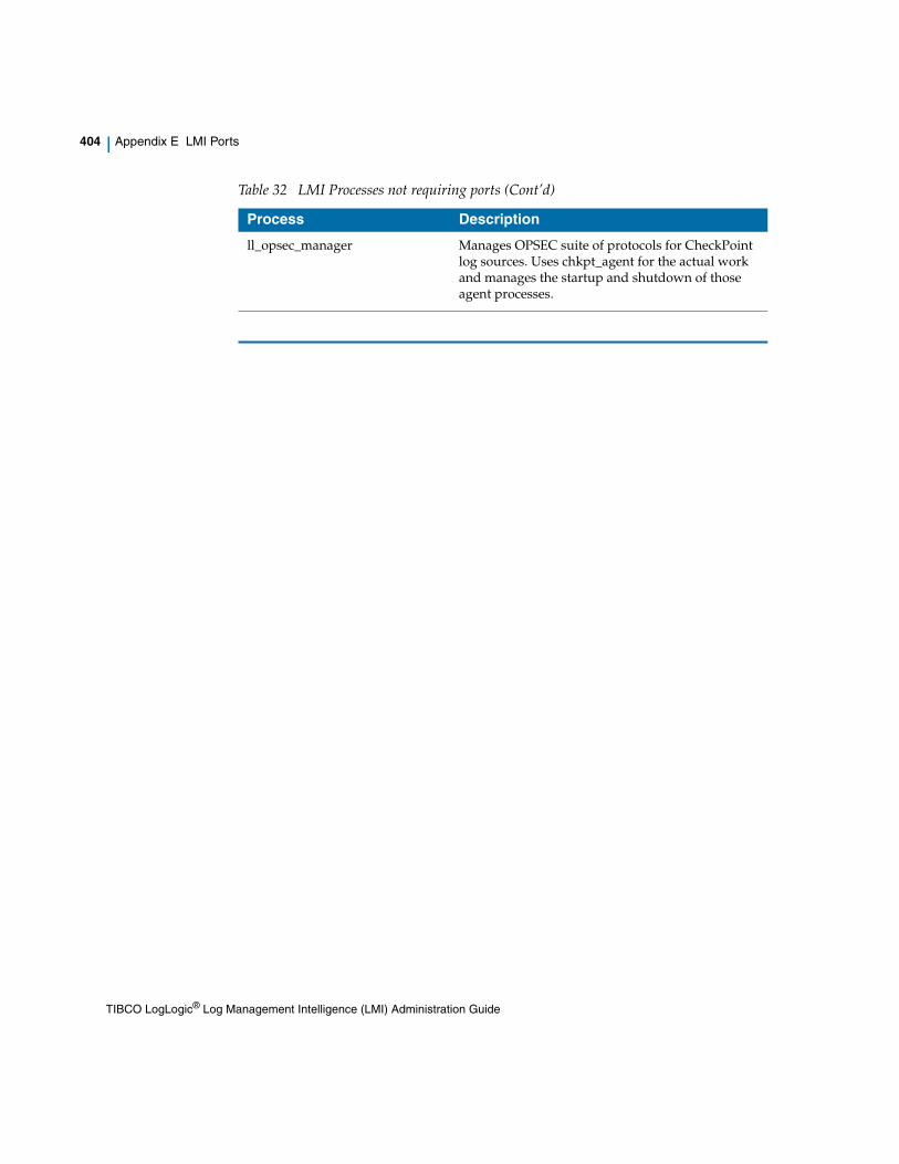
404 | Appendix E LMI Ports
ll_opsec_manager Manages OPSEC suite of protocols for CheckPoint log sources. Uses chkpt_agent for the actual work and manages the startup and shutdown of those agent processes.
Table 32 LMI Processes not requiring ports (Cont’d)
Process Description
TIBCO LogLogic® Log Management Intelligence (LMI) Administration Guide

| 405
Index
A
Active Directory 216groups 240
Active Directory settings 217adding replay rules 120appliance
configuring 326updating software 308
appliancesintroducing 2
archived dataviewing 154
archived data filespassive files 155viewing 154
archiving data 164EMC Centera 168
Archiving Log Data (ST Only) 157
B
backing up the appliance 127
backupabout 127architecture 128disaster recovery 135errors 149HA 135interfaces 129methods 128NFS 142NFS scheduled/immediate 142performance metric 132recommendations 137SAN 144SAN scheduled/immediate 144SCP 138SCP initial setup 138SCP scheduled or immediate 140single system 134status, monitoring 147storage 133what is backed up 130
Backup and Restore 127, 127, 127backup/restore
how it works 131scenarios 134
Blue Coat ProxySGdate and time formats 91
C
Centera 168certificates
SSL 267
TIBCO LogLogic® Log Management Intelligence (LMI) Administration Guide

406 | Index
Check Pointadding firewall 56adding interface 57adding LEA server 54devices 52
CIFS 31Cisco ACS
date and time formats 92Clear Log Data 119clear log data 314CLI
options 325cluster
management station 10collecting compressed files 32Column Manager 73
Export 77export 76Hide columns 75Import 77, 78Show columns 76
command line optionsusing 325, 325
compressed file collection 32compressed files
collecting 32Configuring SAN Archive Storage 166configuring the appliance 326Connecting to the Appliance 326CPMI 51custom logo upload 213customer support xviii
D
data migrationconfiguration 302finishing 305monitoring 304
data retentionLX, MX 219
Data Retention Rules 172Assign Log Sources 175Create New Rule 174Default Rules 173Delete Rules 178Modify Rules 175Prioritize Rules 176
data storageEMC Centera 168NAS 164
date and time formatsfile transfer 91
dbQueueInserts 367dbQueueReads 367device group 41
adding 41devices 22, 46
adding 27Check Point 52managing 22, 46modifying 27
diagnostics 311DB Table Status 312, 312, 312Kernal Ring Buf 312Network 311Restart/Reboot/Shutdown 312
E
EMC Centera 168entities
about 187exporting to XML 189importing 188
exit commandusing 327, 327
Exporting entities 189
TIBCO LogLogic® Log Management Intelligence (LMI) Administration Guide

Index | 407
F
failoverarchitecture 276configuration 284installation 284IP address 276limitations 281management 292metrics 281node failure and recovery 295software upgrade 294
figurestitle 352
File Parallelism 36file transfer
date and time formats 91file transfer history 90file transfer protocols 31file transfer rules 31
adding 33file update 308files
collecting compressed 32compressed, collection 32
firewalladding (Check Point) 56
firewall settings 258forwarding logs 98FTP 31FTPS 31
G
Generic W3Cdate and time formats 92
global groups 41groups
devices 41global 41
H
HAdata migration 301
high availability (HA)see failover
HTTP 31HTTPS 31
I
Importing entities 188input rule
adding 259deleting 263
interfaceadding (Check Point) 57
L
LEAabout 51certificate files backup 130firewall, adding 56interface, adding 57managing 52server, adding 54
log dataclearing 314
log sources 22, 46adding 27managing 22, 46modifying 27
login page, customizing 222LogLogic product families 5LogLogic TCP 101, 106logo, custom 213LX appliances 5
TIBCO LogLogic® Log Management Intelligence (LMI) Administration Guide

408 | Index
M
macAddr 362mail server 215managed appliances
adding users on 238modifying users on 238monitoring 16replicating users on 239
Management Stationabout 10cluster 10creating a cluster 12designating the default appliance 16
managingdevices 22, 46packages 182roles 240SSL certificates 267users 228
managing Check Point devices 52managing device groups 41MD5 checksums, verifying 154message codes
disabled 82enabling 83
message routingabout 98adding 99adding destinations to All Sources rule 100, 317adding destinations to routing rule 110All Sources rule 100creating new outbound rule 104editing destinations 110editing filters 111editing log sources 111removing destinations 112removing rules 111
messageDrops 363messageQueueInserts 362messageQueueReads 362messageTooLong 368MIB
management information base 354
Microsoft IASdate and time formats 93
Microsoft ISAdate and time formats 93
modelSelected 362monitoring managed appliances 16msgRatePer15Min 363msgRatePer5Min 363msgRatePerMin 363msgRatePerSec 369Multithreading Parameters 209MX appliances 6
N
NAS 164, 164NetApp NetCache
date and time formats 93Network Appliance
SnapLock 162network commands
using 328network infrastructure 8network ping command 328network settings 251NFS 142NFS backup 128, 142
O
Object Identifiers 355supported 362
object IDs 355Other File Devices
date and time formats 94
TIBCO LogLogic® Log Management Intelligence (LMI) Administration Guide

Index | 409
P
packagesabout 179adding components 182creating 182deleting 185managing 182removing components 184updating details 184viewing 180, 181
password control 223password, strong 223password, strong (CLI) 335Port Assignments 263port descriptions
adding 86deleting 88modifying 87
private IP address 276private key, importing 272, 273process list 311product families 5productSelected 362protocols
file transfer 31public IP address 276
R
RADIUS 216RADIUS settings 217raid command 330related documents xivremote authentication
Active Directory 216RADIUS 216roles 240TACACS 216
remote authentication server 216remote servers 215
Replay Archived Dataadding replay rules 120cancelling a replay session 124clearing log data 119configuring 118configuring the ST appliance 119environment configuration 115how it works 114LX appliance replay progress 124replay progress 123scheduling 122ST appliance replay progress 123
replay progressviewing 123viewing in the LX appliance 124viewing in the ST appliance 123
replay sessioncancelling 124scheduling 122viewing progress 123
replication 239restore 150
about 127interfaces 129
restore architecture 128retention, data (LX, MX) 219roles 240
Active Directory 240adding 241modifying 241removing 245
RSA ACE Serverdate and time formats 95
rsenderDrops 368rsenderQueueInserts 368rsenderQueueInUse 368rsenderQueueReads 368
S
SAN 144SAN backup 128, 144
TIBCO LogLogic® Log Management Intelligence (LMI) Administration Guide

410 | Index
save commandsusing 332
schedulingreplay sessions 122
SCP 31SCP back up 138SCP backup 128, 138seq 367set clock command 333set commands 333set data migration command 333set dns command 333set ethn command 333, 333set failover command 334set ip command 334set ntpserver command 334set regexsearches command 334set strong_passwd command 335set timezone command 335SFTP 31show commands
using 338SMTP settings 215SnapLock 162SNMP 101, 106
enabling 353overview 352
SNMP trap sink 206, 206, 207, 209, 211, 211software
updating 308Squid
date and time formats 95SSL certificate
CA signed certificate 269certificate & private key import 272, 273LogLogic signed certificate 268managing 267
ST appliances 6startLEAAgent 364startTime 368static routes 254
adding 254, 254adding multiple 254, 255removing 255
Storage Area Network (SAN) 166
strong passwords 223support, contacting xviiiSyslog Header character sets 388, 394system access command 341system commands
using 341system halt command 341system iptables command 341system keycopy command 341system passwd command 342system performance settings 211system reboot command 342system settings 201
custom logo upload 213data retention (LX, MX) 219general 202login page 222password control 223remote authentication server 216remote servers 215SMTP 215SNMP trap sink 206, 206, 207, 209, 211, 211system performance 211time 221
System StatusManagement Station 16
system update command 342
T
TACACS 216TACACS settings 217TCP syslog 101, 106technical support xviiitime settings 221Timeout 209totalAcceptedSyslogMessages 366totalApprovedSyslogMessages 365totalDeniedSyslogMessages 366totalFTPSyslogMessages 366totalLEAMessages 364totalLEAServers 364totalNortelVPNAuthMessages 367
TIBCO LogLogic® Log Management Intelligence (LMI) Administration Guide
Index | 411
totalOtherSyslogMessages 365totalProcessedMessages 365totalSecuritySyslogMessages 366totalSkippedSyslogMessages 365totalSyslogMessages 364totalSyslogReceivers 363totalSyslogSources 363totalSystemSyslogMessages 366totalTrapReceivers 364totalUnapprovedLEAMessages 365totalUnapprovedSyslogMessages 366totalUnknownSyslogMessages 365totalURLSyslogMessages 367totalUsers 364totalVPNMessages 367
U
UDP syslog 101, 106unset data migration command 347unset net command 347updating appliance software 308user roles 3users
adding 230adding on managed appliances 238associating with devices 235general settings 231, 241managing 228modifying 230modifying on managed appliances 238privilege options 233, 242removing 237replicating on managed appliances 239setting privileges 232, 242
V
view data files 154viewing replay progress 123, 123, 124
W
watch command 348
TIBCO LogLogic® Log Management Intelligence (LMI) Administration Guide