TI Spins Motors Motor Solutions Guide - Farnell element14 · Motor Solutions Guide 2 T ... • PC...
17
2H 2011 www.ti.com/motor TI Spins Motors Motor Solutions Guide
Transcript of TI Spins Motors Motor Solutions Guide - Farnell element14 · Motor Solutions Guide 2 T ... • PC...

2Motor Solutions Guide Texas Instruments 2H 2011
➔
Motor Solutions Guide
Contents
Texas Instruments (TI) is a global market leader that provides complete motor-drive and control solutions along with broad analog and microcontroller portfolios. TI offers compre hensive tools, software and support to deliver efficient, reliable, cost-effective motor solutions. Customers can get the right products with the right per-formance to quickly spin motors such as AC induction motors (ACIMs), brushed DC motors, brushless DC (BLDC) motors, permanent-magnet synchronous motors (PMSMs) and stepper motors.
When you want the broadest motor expertise, breadth of selection and comprehensive support, you want TI as your partner for efficient, reliable and cost-effective motor-drive and control solutions.
Motor Control System Functions
Host – Motion profile, logic controller or user interface, often communicating over a standard or proprietary field bus (CAN, serial, Ethernet).
Digital Isolation – Protection and level shifting between different voltage levels.
Controller – Generates the proper switching patterns to control the motor’s motion based on feedback and motion profile information from the host.
Gate Drivers – Generate the necessary voltage and current required to accu-rately and efficiently drive the MOSFETS or IGBTs.
Integrated Motor Driver
Pre-Driver
PowerStage
(IGBTs orMOSFETs)
Sensing(Torque,Speed,
Position)
DigitalIsolation
Host, User Interface,Network
Controller/MCU
GateDrivers
Introduction . . . . . . . . . . . . . . . . . . . . . . . . . . . . . . . 2
Complete TI Motor-Drive SolutionsStepper Motors . . . . . . . . . . . . . . . . . . . . . . . . . . . . . . 3Brushed DC Motors . . . . . . . . . . . . . . . . . . . . . . . . . . . 3Brushless DC (BLDC) Motors. . . . . . . . . . . . . . . . . . . . 4Permanent Magnet Synchronous Motors (PMSMs). . . 4AC Induction Motors (ACIMs). . . . . . . . . . . . . . . . . . . . 5
DRV8x Integrated Motor Drivers . . . . . . . . . . . 6
Signal Chain SolutionsCurrent-Sense Amplifiers . . . . . . . . . . . . . . . . . . . . . . . 7Industrial Communications (Interface) . . . . . . . . . . . . . 7Discrete Analog-to-Digital Converters (ADCs) . . . . . . . 8Digital Isolators. . . . . . . . . . . . . . . . . . . . . . . . . . . . . . . 9
Microcontrollers for Motor Control32-Bit Real-Time TMS320C2000™ Microcontrollers . 10Stellaris® 32-Bit ARM® Cortex®-M3 Microcontrollers . 11TMS570 ARM Cortex-R4F Microcontrollers . . . . . . . 1216-Bit Ultra-Low-Power MSP430™ Microcontrollers . 13
Selection GuidesDRV8x Motor Drivers . . . . . . . . . . . . . . . . . . . . . . . . . 14Industrial Ethernet Physical Layer Transceiver. . . . . . 14CAN Transceivers . . . . . . . . . . . . . . . . . . . . . . . . . . . . 15Digital Isolators. . . . . . . . . . . . . . . . . . . . . . . . . . . . . . 15RS-485/RS-422 Transceivers. . . . . . . . . . . . . . . . . . . 15
TI Worldwide Technical Support. . . (back cover)
➔ Introduction
Power Stage – IGBTs or MOSFETS
Sensing – Analog circuitry which pro-cesses/conditions the feedback from the motor to control torque, speed or position.
Pre-Driver – Gate drivers, sensing and protection circuitry integrated into a single device or package that may also include control logic.
Integrated Motor Driver – Gate driver, FETs and protection circuitry integrated into a single device or package that may also include control logic and sensing circuitry.
www.ti.com/motor
3Motor Solutions Guide Texas Instruments 2H 2011
➔
Complete TI Motor-Drive Solutions
Stepper Motors
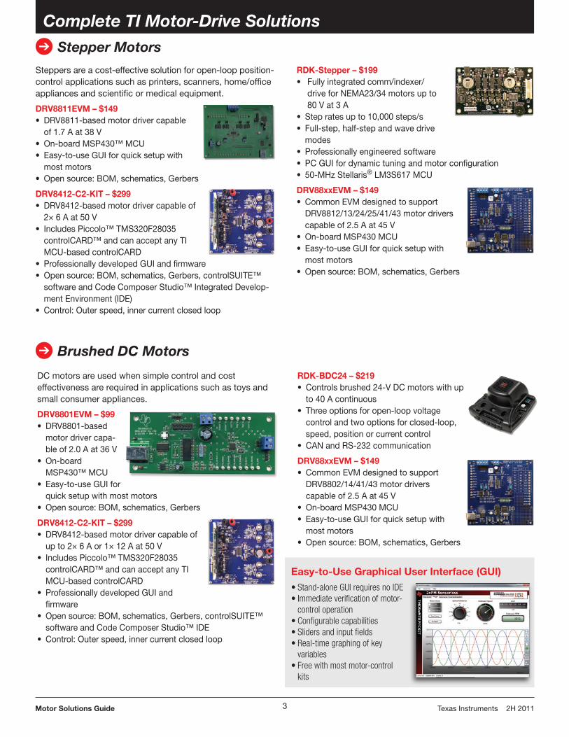
DC motors are used when simple control and cost effectiveness are required in applications such as toys and small consumer appliances.
DRV8801EVM – $99• DRV8801-based
motor driver capa-ble of 2.0 A at 36 V
• On-board MSP430™ MCU
• Easy-to-use GUI for quick setup with most motors
• Open source: BOM, schematics, Gerbers
DRV8412-C2-KIT – $299• DRV8412-based motor driver capable of
up to 2× 6 A or 1× 12 A at 50 V• Includes Piccolo™ TMS320F28035
controlCARD™ and can accept any TI MCU-based controlCARD
• Professionally developed GUI and firmware
• Open source: BOM, schematics, Gerbers, controlSUITE™ software and Code Composer Studio™ IDE
• Control: Outer speed, inner current closed loop
Steppers are a cost-effective solution for open-loop position-control applications such as printers, scanners, home/office appliances and scientific or medical equipment.
DRV8811EVM – $149• DRV8811-based motor driver capable
of 1.7 A at 38 V• On-board MSP430™ MCU• Easy-to-use GUI for quick setup with
most motors• Open source: BOM, schematics, Gerbers
DRV8412-C2-KIT – $299• DRV8412-based motor driver capable of
2× 6 A at 50 V• Includes Piccolo™ TMS320F28035
controlCARD™ and can accept any TI MCU-based controlCARD
• Professionally developed GUI and firmware• Open source: BOM, schematics, Gerbers, controlSUITE™
software and Code Composer Studio™ Integrated Develop-ment Environment (IDE)
• Control: Outer speed, inner current closed loop
RDK-Stepper – $199• Fully integrated comm/indexer/
drive for NEMA23/34 motors up to 80 V at 3 A
• Step rates up to 10,000 steps/s• Full-step, half-step and wave drive
modes• Professionally engineered software• PC GUI for dynamic tuning and motor configuration• 50-MHz Stellaris® LM3S617 MCU
DRV88xxEVM – $149• Common EVM designed to support
DRV8812/13/24/25/41/43 motor drivers capable of 2.5 A at 45 V
• On-board MSP430 MCU• Easy-to-use GUI for quick setup with
most motors• Open source: BOM, schematics, Gerbers
➔ Brushed DC Motors
RDK-BDC24 – $219• Controls brushed 24-V DC motors with up
to 40 A continuous• Three options for open-loop voltage
control and two options for closed-loop, speed, position or current control
• CAN and RS-232 communication
DRV88xxEVM – $149• Common EVM designed to support
DRV8802/14/41/43 motor drivers capable of 2.5 A at 45 V
• On-board MSP430 MCU• Easy-to-use GUI for quick setup with
most motors• Open source: BOM, schematics, Gerbers
Easy-to-Use Graphical User Interface (GUI)
•Stand-aloneGUIrequiresnoIDE•Immediateverificationofmotor-controloperation
•Configurablecapabilities•Slidersandinputfields•Real-timegraphingofkeyvariables
•Freewithmostmotor-controlkits
➔
4Motor Solutions Guide Texas Instruments 2H 2011
Complete TI Motor-Drive Solutions
Brushless DC (BLDC) Motors
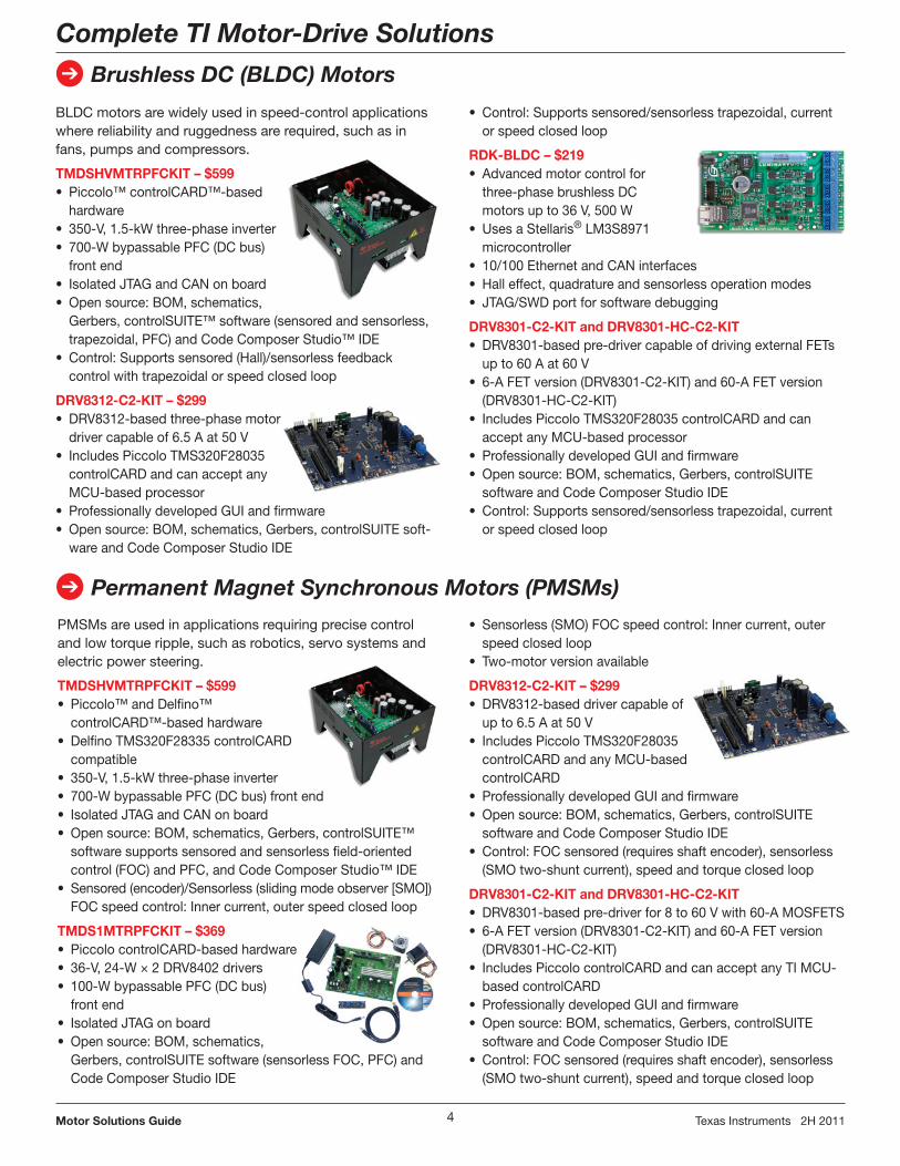
PMSMs are used in applications requiring precise control and low torque ripple, such as robotics, servo systems and electric power steering.
TMDSHVMTRPFCKIT – $599• Piccolo™ and Delfino™
controlCARD™-based hardware• Delfino TMS320F28335 controlCARD
compatible• 350-V, 1.5-kW three-phase inverter• 700-W bypassable PFC (DC bus) front end• Isolated JTAG and CAN on board• Open source: BOM, schematics, Gerbers, controlSUITE™
software supports sensored and sensorless field- oriented control (FOC) and PFC, and Code Composer Studio™ IDE
• Sensored (encoder)/Sensorless (sliding mode observer [SMO]) FOC speed control: Inner current, outer speed closed loop
TMDS1MTRPFCKIT – $369• Piccolo controlCARD-based hardware• 36-V, 24-W × 2 DRV8402 drivers• 100-W bypassable PFC (DC bus)
front end• Isolated JTAG on board• Open source: BOM, schematics,
Gerbers, controlSUITE software (sensorless FOC, PFC) and Code Composer Studio IDE
BLDC motors are widely used in speed-control applications where reliability and ruggedness are required, such as in fans, pumps and compressors.
TMDSHVMTRPFCKIT – $599• Piccolo™ controlCARD™-based
hardware• 350-V, 1.5-kW three-phase inverter• 700-W bypassable PFC (DC bus)
front end• Isolated JTAG and CAN on board• Open source: BOM, schematics,
Gerbers, controlSUITE™ software (sensored and sensorless, trapezoidal, PFC) and Code Composer Studio™ IDE
• Control: Supports sensored (Hall)/sensorless feedback control with trapezoidal or speed closed loop
DRV8312-C2-KIT – $299• DRV8312-based three-phase motor
driver capable of 6.5 A at 50 V• Includes Piccolo TMS320F28035
controlCARD and can accept any MCU-based processor
• Professionally developed GUI and firmware • Open source: BOM, schematics, Gerbers, controlSUITE soft-
ware and Code Composer Studio IDE
• Control: Supports sensored/sensorless trapezoidal, current or speed closed loop
RDK-BLDC – $219• Advanced motor control for
three-phase brushless DC motors up to 36 V, 500 W
• Uses a Stellaris® LM3S8971 microcontroller
• 10/100 Ethernet and CAN interfaces• Hall effect, quadrature and sensorless operation modes• JTAG/SWD port for software debugging
DRV8301-C2-KIT and DRV8301-HC-C2-KIT• DRV8301-based pre-driver capable of driving external FETs
up to 60 A at 60 V• 6-A FET version (DRV8301-C2-KIT) and 60-A FET version
(DRV8301-HC-C2-KIT)• Includes Piccolo TMS320F28035 controlCARD and can
accept any MCU-based processor• Professionally developed GUI and firmware• Open source: BOM, schematics, Gerbers, controlSUITE
software and Code Composer Studio IDE• Control: Supports sensored/sensorless trapezoidal, current
or speed closed loop
➔ Permanent Magnet Synchronous Motors (PMSMs)
• Sensorless (SMO) FOC speed control: Inner current, outer speed closed loop
• Two-motor version available
DRV8312-C2-KIT – $299• DRV8312-based driver capable of
up to 6.5 A at 50 V• Includes Piccolo TMS320F28035
controlCARD and any MCU-based controlCARD
• Professionally developed GUI and firmware• Open source: BOM, schematics, Gerbers, controlSUITE
software and Code Composer Studio IDE• Control: FOC sensored (requires shaft encoder), sensorless
(SMO two-shunt current), speed and torque closed loop
DRV8301-C2-KIT and DRV8301-HC-C2-KIT• DRV8301-based pre-driver for 8 to 60 V with 60-A MOSFETS• 6-A FET version (DRV8301-C2-KIT) and 60-A FET version
(DRV8301-HC-C2-KIT)• Includes Piccolo controlCARD and can accept any TI MCU-
based controlCARD• Professionally developed GUI and firmware• Open source: BOM, schematics, Gerbers, controlSUITE
software and Code Composer Studio IDE• Control: FOC sensored (requires shaft encoder), sensor less
(SMO two-shunt current), speed and torque closed loop
➔
5Motor Solutions Guide Texas Instruments 2H 2011
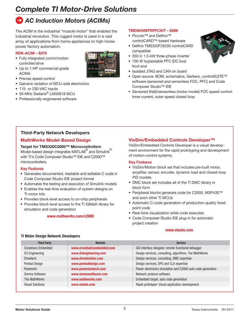
The ACIM is the industrial “muscle motor” that enabled the industrial revolution. This rugged motor is used in a vast array of applications from home appliances to high- horse-power factory automation.
RDK-ACIM – $379• Fully integrated comm/motion
controller/drive• Up to 1-HP commercial-grade
ACIMs• Precise speed control• Galvanic isolation of MCU-side electronics• 115- or 230-VAC inputs• 50-MHz Stellaris® LM3S818 MCU• Professionally engineered software
Complete TI Motor-Drive Solutions
AC Induction Motors (ACIMs)
TMDSHVMTRPFCKIT – $599• Piccolo™ and Delfino™
controlCARD™-based hardware• Delfino TMS320F28335 controlCARD
compatible• 350-V, 1.5-kW three-phase inverter• 700-W bypassable PFC (DC bus)
front end• Isolated JTAG and CAN on board• Open source: BOM, schematics, Gerbers, controlSUITE™
software (sensored and sensorless FOC, PFC) and Code Composer Studio™ IDE
• Sensored (Hall)/sensorless (motor model) FOC speed control: Inner current, outer speed closed loop
MathWorks Model-Based DesignTarget for TMS320C2000™ MicrocontrollersModel-based design integrates MATLAB
® and Simulink
®
with TI’s Code Composer Studio™ IDE and C2000™ microcontrollers.
Key Features• Generates documented, readable and editable C code in
Code Composer Studio IDE project format• Automates the testing and execution of Simulink models• Enables the real-time evaluation of system designs on
TI motor kits• Provides block-level access to on-chip peripherals• Provides block-level access to the TI IQMath library for
simulation and code generation
www.mathworks.com/c2000
VisSim/Embedded Controls Developer™VisSim/Embedded Controls Developer is a visual develop-ment environment for the rapid prototyping and development of motion-control systems.
Key Features• VisSim/Motion block set that includes pre-built motor,
amplifier, sensor, encoder, dynamic load and closed-loop PID models
• DMC block set includes all of the TI DMC library in block form
• Peripheral blocks generate code for C2000, MSP430™ and soon other TI MCUs
• Automatic C-code generation of production-quality fixed-point code
• Real-time visualization while code executes• Code Composer Studio IDE plug-in for automatic
project creation
www.vissim.com
TI Motor Design Network Developers
Third Party Website Service
Crosshairs Embedded www.crosshairsembedded.com GUI interface designer, remote functional debuggerD3 Engineering www.d3engineering.com Design services, consulting, algorithms, The MathWorksDrivetech www.drivetechinc.com Design services, consulting, DMC expertisePentad Design www.pentaddesign.com Design services, DPS and CLA expertisePowersim www.powersimtech.com Power electronics simulation and C2000 auto code generationSimma Software www.simmasoftware.com Network protocol softwareThe MathWorks www.mathworks.com Embedded target, auto code generationVisual Solutions www.vissim.com Rapid prototyper: Visual application development
Third-Party Network Developers

6Motor Solutions Guide Texas Instruments 2H 2011
➔
DRV8x Integrated Motor Drivers
The DRV8x family of integrated motor drivers enables customers to quickly and easily spin their motors. Integrated drivers have higher performance, better protection, and require less board space than traditional discrete solutions. Futhermore, they do not require design expertise for discrete drive stages, which greatly simplifies and speeds the design process.
The TI Advantage
Quicker Time to SpinWith an integrated drive stage, current sensing, on-chip control logic, simple control interfaces, easy-to-use EVMs and design-in documentation, custom-ers can quickly get their motors up and spinning.
GateDriver FETsControl
Protection/Current Sensing
DRV8x Integrated Motor Driver
Latest DRV8x Motor Drivers Reduce RDS(on) by 60%
MotorType Device Voltage
Current (Peak)
Current Levels Control
BrushedDRV8814 8.2 to 45 V 2.5 A – PH/EN
DRV8840 8.2 to 45 V 5.0 A – PH/EN
Stepper
DRV8813 8.2 to 45 V 2.5 A 4× PH/EN
DRV8825 8.2 to 45 V 2.5 A 1/32 µ-step Indexer
DRV8829 8.2 to 45 V 5.0 A 32× PH/EN
Brushedand
Stepper
DRV8841 8.2 to 45 V 2.5 A 4× PWM
DRV8843 8.2 to 45 V 2.5 A 4× PWM
DRV8842 8.2 to 45 V 5.0 A 32× PWM
See selection table on page 14 for a complete New products are listed in bold red.list of DRV8x motor drivers.
3-Phase Brushless Motor Pre-DriverDRV8301
Key Features• Integrated three-phase gate driver with
dual current-shunt amplifiers and buck converter for MCU or system power needs
• Wide input-voltage range (8 to 60 V)• Supports up to 1.7-A gate current• Intelligent gate drive
and cross- conduction prevention
• Overcurrent (OC) protection of external FETs with pro-grammable cycle-by-cycle current limit
• SPI interface for programmability
DRV8301
MotorController
BuckConverter
Offset+
+
–
–
Vs PWM
SPI
ADC1
ADC2
Vref
ErrorReporting
3 or 6
Offset
3-PhaseNMOSGate
Driver
PVDD
GH_A
GL_A
GH_B
GL_B
GH_C
Motor
GL_CControl
andProtection
Logic
www.ti.com/drv8x
Robust, Reliable and Fully Protected All of TI’s motor drivers include fast-acting protection against short circuits, thermal overload, undervoltage and shoot-through. When a fault condition is detected, the H-Bridge is quickly shut down to protect the motor and driver IC.
The Right Part for Each ApplicationTI has a broad portfolio of motor drivers with different levels of integration, multiple control interfaces and a wide range of power ratings. The DRV8x family includes both drivers and pre-drivers and supports voltage ranges from 2.75 to 60 V and load current from 100 mA to 24 A.
Benefits• Reduced board space and improved
performance• Automatic handshake of high-side
and low-side FET transition to prevent shoot-through, simplify gate control and improve system reliability
• External FETs improve thermal perform ance and efficiency and can easily scale to support both low- and high-current platforms

7Motor Solutions Guide Texas Instruments 2H 2011
➔
Signal Chain Solutions
Current-Sense Amplifiers
Low Offset is the TI AdvantageOffset and offset-drift performance are factors that determine the full-scale input voltage to the current-sense amplifier and, subsequently, the size of the shunt resistor. Lower offset allows for smaller shunt resistors and results in less voltage drop and power loss.
To avoid errors introduced by external gain resistors, all TI current-sense ampli-fiers have gain set internally through TI’s precision manufacturing processes. Total component count and board space are reduced as well. In addition to the stan-dard configuration of current-sense amplifiers, TI has a line of digital-output current-sense devices. These devices make isolation easy by limiting the inter-face to two digital lines, which frees embedded data converters for other system activities.
High Precision for Large Common-Mode Current Measurements
+80 V
2.7 to 18 V 2.7 to 18 V
RefRef
+INA282–
+INA282–
RS-485/RS-422 • Broad portfolio • Improved speed, performance and
robustness
Speed• Speeds of up to 50 Mbps
Functionality• Lower unit load: Up to 256 devices
on bus • 3.3-V supply: No need for extra
voltage regulators• True fail-safe: No need for external
biasing resistors• Slow-rate control reduces EMI• Receiver equalization enables long
cable transmission
Robustness• Best-in-class ESD protection: Improved
reliability• 400-W transient voltage protection: No
need for external components• Extended common mode: Extends
transmission distance
CAN• Broad portfolio of standard industry
upgrades and TI-unique CAN devices• 5-V CAN transceiver offers the highest
ESD protection in the industry: 14 kV
Second-Generation 3.3-V CAN Transceivers• Lowest power and ±36-V protection• Low-power standby with bus wake-up• 5-µA standby power
Wide Common-Mode Current-Sense Amplifiers
Device CMR Offset Offset Drift Bidirectional
INA282 –14 to 80 V 70 μV 0.5 μV/°C Yes
INA138/INA139 2.7 to 36 V 1 mV 1 μV/°C No
INA168/INA169 2.7 to 60 V 1 mV 1 μV/°C No
INA170 2.7 to 60 V 1 mV 1 μV/°C Yes
INA193-INA198 –16 to 80 V 2 mV 2.5 μV/°C No
➔ Industrial Communications (Interface)
Isolated Interface• Integrated interface with isolation• Uses TI’s new differential capacitive
technology • High performance, superior to optical
and magnetic isolation • Integrated design saves board space
and simplifies board design
➔
8Motor Solutions Guide Texas Instruments 2H 2011
Signal Chain Solutions
Discrete Analog-to-Digital Converters (ADCs)
Delta-Sigma Modulators in Current Measurement and Motor Control
TM
S32
0F28
0xx
DS
P
AMC1203/4
AMC1203/4
ADS1205/9 AM
C12
10
PWM Excitation
Resolversincos
InverterAC/DC
UV
W
Load
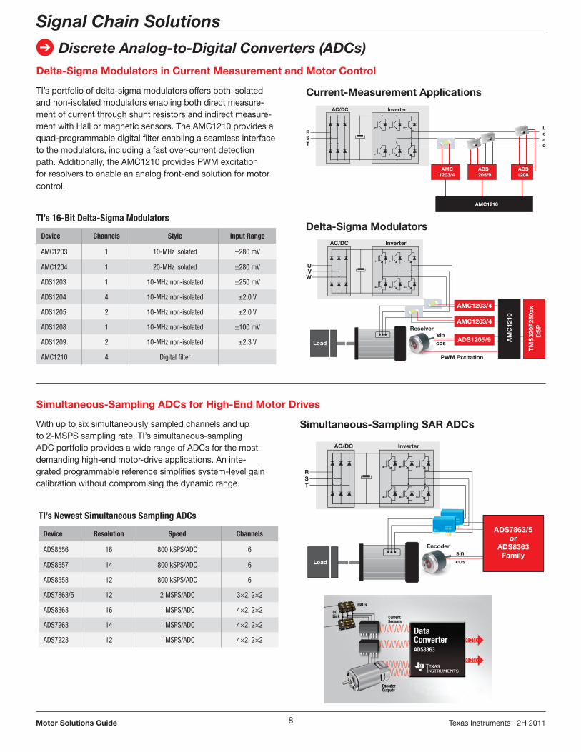
TI’s 16-Bit Delta-Sigma Modulators
Device Channels Style Input Range
AMC1203 1 10-MHz isolated ±280 mV
AMC1204 1 20-MHz Isolated ±280 mV
ADS1203 1 10-MHz non-isolated ±250 mV
ADS1204 4 10-MHz non-isolated ±2.0 V
ADS1205 2 10-MHz non-isolated ±2.0 V
ADS1208 1 10-MHz non-isolated ±100 mV
ADS1209 2 10-MHz non-isolated ±2.3 V
AMC1210 4 Digital filter
AC/DC
RST
Load
Inverter
AMC1203/4
ADS1208
AMC1210
ADS1205/9
AC/DC
RST
Inverter
cossin
Encoder
Load
ADS7863/5or
ADS8363Family
Simultaneous-Sampling ADCs for High-End Motor Drives
Simultaneous-Sampling SAR ADCs
Current-Measurement Applications
Delta-Sigma Modulators
TI’s Newest Simultaneous Sampling ADCs
Device Resolution Speed Channels
ADS8556 16 800 kSPS/ADC 6
ADS8557 14 800 kSPS/ADC 6
ADS8558 12 800 kSPS/ADC 6
ADS7863/5 12 2 MSPS/ADC 3×2, 2×2
ADS8363 16 1 MSPS/ADC 4×2, 2×2
ADS7263 14 1 MSPS/ADC 4×2, 2×2
ADS7223 12 1 MSPS/ADC 4×2, 2×2
TI’s portfolio of delta-sigma modulators offers both isolated and non-isolated modulators enabling both direct measure-ment of current through shunt resistors and indirect measure-ment with Hall or magnetic sensors. The AMC1210 provides a quad-programmable digital filter enabling a seamless interface to the modulators, including a fast over-current detection path. Additionally, the AMC1210 provides PWM excitation for resolvers to enable an analog front-end solution for motor control.
With up to six simultaneously sampled channels and up to 2-MSPS sampling rate, TI’s simultaneous-sampling ADC portfolio provides a wide range of ADCs for the most demanding high-end motor-drive applications. An inte-grated programmable reference simplifies system-level gain calibration without compromising the dynamic range.

➔
9Motor Solutions Guide Texas Instruments 2H 2011
Isolated Gate DriversISO55xx Family
100
200VPeak (Continuous)
Life
time
in Y
ears
600 100080040010
62
40
85
59
43 TJ = 85°C
TJ = 150°C31
23
28
20
1511
The TI Edge
ReliabilityTI offers proven reliability of silicon- dioxide (SiO2) insulation that is stable over temperature and moisture and has a life span of over 25 years.
Highest Noise ImmunityTI uses differential signals to cross the isolation barrier, giving the highest immunity from external magnetic and electric fields to prevent data corruption.
Signaling RateTI offers digital isolators with high signal-ing rates of up to 150 Mbps, with low skew and pulse-width distortion.
Lowest JitterTo ensure signal integrity, jitter reduction is a priority. ISO7xxx products offer the lowest jitter of 1-ns jitter at 150-Mbps PRBS NRZ data input.
TI’s ISO55xx products are isolated gate drivers for IGBTs with power ratings up to 150 A and 1200 V.
The input TTL logic and output power stage are separated by TI’s silicon- dioxide (SiO2) isolation barrier.
When used in conjunction with isolated power supplies, the device blocks high voltage, isolates grounds and prevents noise currents from entering the local ground and interfering with or damaging sensitive circuitry.
Key Features• Soft IGBT turn-off• Isolated fault feedback• VCE DESAT protection/adjustability• Undervoltage lock-out (UVLO) protec-
tion with hysteresis• ±50-kV/µs typical transient immunity• 5000-Vrms maximum isolation per UL• Operates with 3.3-V or 5-V input
supply• –40 to 125°C operating range
μC
PWM
FAULT
M3-Phase
Input
ISO 5500
ISO 5500
ISO 5500
ISO 5500
ISO 5500
ISO 5500
Isolation Barrier
Signal Chain Solutions
Digital Isolators
Resources Available• EVMs• IBIS models• Application notes on high-voltage life-
time and magnetic-field immunity
TI ISO Life Expectancy vs. Voltage

10Motor Solutions Guide Texas Instruments 2H 2011
➔
Microcontrollers for Motor Control
32-Bit Real-Time TMS320C2000™ Microcontrollers
Broadest MCU Architecture• 40- to 300-MHz TMS320C28x™ CPU• Built-in DSP functions• Single-cycle 32×32-bit MAC
Real-Time Control• Optimized core• Fast interrupts• Flexible interrupt system• Best-in-class ADC performance• Real-time debugging• Flexible, high-resolution PWMs• Sensor interfaces• CAN, serials
Overall System-Performance Optimization• High level of integration• Control and supervision• Variable-speed real-time control• Better dynamic and transient control• Simulation, prototyping and automatic
code generation from The MathWorks, VisSim and PowerSim
• Software libraries for industrial safety certification such as IEC60730 and IIEC61508
Piccolo™ MCU Family for Lowest System Cost• Integrated OSC, watchdogs• Analog comparators• Fault detection• Limited life support• No external GPIO filters needed
Application LibrariesSpecialized, application-specific soft-ware functions: • Modular macros with variable I/Os• At initialization, all variables are
defined and outputs of one block are set as inputs to the next
• Complete documentation – including source code, use and technical theory – is provided for every module
Applications• HVAC compressors and blowers• Industrial motors• Variable-speed fans and pumps• Automotive power steering,
traction and pumps• Premium e-bikes• Laundry machines• Medical pumps and blowers
Ex: Using “Park” from DMC Library
//initialization code, define macro per library#definePARK_MACRO(v)v.Ds=_IQmpy(v.Alpha,v.Cosine)+_IQmpy(v.Beta,v.Sine);v.Qs=_IQmpy(v.Beta,v.Cosine)-_IQmpy(v.Alpha,v.Sine);
//incremental build code, connect outputs and inputspark1.Alpha=clarke1.Alpha;park1.Beta=clarke1.Beta;
//run-time code, call the functionPARK_MACRO(park1)
Is1
Is2
Is3
Iα
Iβ
Id (flux component)
Iq (torque component)
Digital Motor Control (DMC) Library
www.ti.com/c2000dmc
Transforms and Estimators• Clarke, Park, sliding mode observer
(SMO), phase voltage, resolver, flux, speed calculators and estimators
Control• Signal generation, closed-loop PID,
BEMF commutation, space vector generators, microstep SIN/COB tables
Peripheral Drivers• Different modes and topology support• ADC, PWM, encoders, sensor
captures, DAC outputs
IQMath LibraryThe IQMath library is a library and compiler intrinsic that allows you to select your range and resolution by choosing which bits of your binary represented number are the integer (I) and which are the quotient (Q). It also allows you to write C functions in floating point instead of dealing with fixed-point scaling.• Change numerical range on the fly• Tune for best resolution and
dynamic range• Remove quantization effects• Reduce scaling and saturation• Better integration with simulation
and code-generation tools• Single source set between fixed
and floating point
C2000™ Device Features www.ti.com/c2000
Feature
Fixed-Point Delfino™ Series Piccolo™ Series
F281x F280x F2823x F2833x C2834x F2802x F2803x F2806x
Mass Production 2003 2005 2008 2008 2009 2009 2010 2011
C28x™ CPU Fixed Fixed Fixed Float Float Fixed Fixed + CLA Option
Floating Point + CLA + VCU
MHz 150 60 to 100 100 to 150 100 to 150 200 to 300 40 to 60 60 80
Pins 128 to 179 100 176 to 179 176 to 179 176 to 256 38 to 56 64 to 80 80 to 100
Flash (KB) 128 to 256 32 to 256 128 to 512 128 to 512 0 16 to 64 32 to 128 128 to 256
RAM (KB) 36 12 to 36 52 to 68 52 to 68 196 to 516 4 to 12 12 to 20 52 to 100
Budgetary Pricing $13 to $15 $3 to $13 $13 to $14 $14 to $16 $9 to $16 $1.85 to $3 $3 to $4.50 $4.95 to $7

➔
11Motor Solutions Guide Texas Instruments 2H 2011
Microcontrollers for Motor Control
Stellaris® 32-Bit ARM® Cortex®-M3 Microcontrollers
Texas Instruments is the industry leader in bringing 32-bit capabilities and the full benefits of ARM Cortex-M3-based microcontrollers to market. Stellaris MCUs with Cortex-M3 offer a direct path to the strongest ecosystem of develop-ment tools, software and knowledge in the industry. Designers who migrate to Stellaris MCUs will benefit from great tools, small code footprint and outstand-ing performance. Even more important, designers can enter the ARM ecosystem with full confidence in a compatible road-map from $1 to 1 GHz. You will never need to change architectures again.
With large on-chip memories, enhanced power management and expanded I/O and control capabilities, Stellaris MCUs are optimized for industrial applications requiring reliable connectivity, precise motor/motion control and remote moni-toring. Some typical applications are factory automation, HVAC and building control, gaming equipment, medical instrumentation, consumer appliances, CCTV monitoring and fire security.
Precision Motion ControlThe Stellaris family of ARM Cortex-M3 microcontrollers features deterministic performance and IP especially designed for simultaneous advanced motion con-trol and real-time connectivity. These microcontrollers include up to eight full
Stellaris® Robotic Evaluation Boards
Afunwayforseriousembedded-systemsprogrammers,consumers,hobbyistsandstudentstoworkwithandlearnStellarisARM®Cortex®-M3embeddedprogram-mingwithavarietyofoperatingsystemsandARMtooloptions.Ordernowatwww.ti.com/evalbot
channels of control with deadband gen-erators and shoot-through protection for applications such as three-phase inverter bridges. Fault-condition handling in hardware quickly provides low-latency shutdown and synchronization of timers to enable precise alignment of all edges. • Motion-control PWMs with deadband
and fault detection support safe and efficient operation of motors
• Quadrature encoder inputs (QEIs) support incremental encoders, tachometers, generators/resolvers and TDC detectors
• High-speed ADCs support current measurement using Hall sensors or shunts to optimize algorithms
• Independent integrated analog compar-ators can be configured to drive an out-put or generate an ADC interrupt event
Key Features• Industry-leading ARM Cortex-M3 core• 8 to 512KB of flash• 20- to 80-MHz CPU clock speeds• Deterministic fast-interrupt processing
(12 cycles)• Real-time multitasking capabilities• Integrated analog peripherals• 10-bit and 12-bit analog-to-digital
converter• Pulse-width modulators (PWMs) with
programmable deadband timers• Operating modes with clock gating for
lower power
Unique Stellaris MCU Capabilities• Advanced communication capabilities,
including 10/100 Ethernet MAC/PHY, USB, USB OTG, CAN controllers, I2C, I2S and extended peripheral interfaces
• 5-V tolerant GPIOs with programmable drive capability
• Single-cycle flash up to 50 MHz• Royalty-free StellarisWare® software• Open-tooled reference design kits and
quick-start evaluation kits• Up to two quadrature encoder inputs
StellarisWare Software• Extensive suite of software designed
to reduce development cycle time• Stellaris peripheral libraries• Stellaris USB libraries• Stellaris graphics libraries• Stellaris code examples• Stellaris IEC 60730 library• Available as object library and
source code
Hardware Kits• Schematics, BOM and Gerber files
are available for all hardware kits and include all accessories to start evalua-tion right out of the box.
Reference Designs
Design Description
RDK-Stepper Stepper Motor Reference Design Kit
RDK-ACIM AC Induction Motor Reference Design Kit
RDK-BLDC Brushless DC Motor Reference Design Kit
RDK-BDC Brushed DC Motor Reference Design Kit
RDK-S2E Serial-to-Ethernet Reference Design Kit
RDK-IDM Intelligent Display Module Reference Design Kit
For more information on Stellaris MCUs for motor-control applications, visit www.ti.com/stellarismotorcontrol
➔
12Motor Solutions Guide Texas Instruments 2H 2011
Microcontrollers for Motor Control
TMS570 ARM® Cortex®-R4F Microcontrollers
Serial I/F Network I/F
Enhanced Peripheral Bus
DMAEnhanced System Bus and Vectored Interrupt Management
Control
Power, Clock and SafetyMemory
ARM®
Cortex®-RF4160 MHz
Memory Interface
CoprocessorTimers
High-EndTime w/DMA
32-ch2x UART (2 LIN)
2x SPI
3x MibSPI
GIOB (8)
3x CAN
2-ch FlexRay®
2/DMA
GIOA/INT (8)
2x MibADC12-bit, 24-ch
Fail-safeDetection Embedded Trace
JTAG Debug
Calibration
Memory Protection
Up to 160KBRAM w/ECC
Up to 2MB Flashw/ECC
RTI/DWD
CRC
Reset
LBIST
PBIST
OSC PLL
Asynch EMIF
TMS570LS20216
TMS570 Microcontroller
BLDCMotor
Absolute AngleSensor
(sine/cosine)
Hall Elements
IncrementalEncoder
NHET functionsshown here areprogrammable
Battery
Temperature PCB
Phase Currents and Voltages6
6
3
3
3
6
1
3-Phase Inverter Bridge
Position/speed measurement(Usually just one of the three shown sensor types used)
Measure Back PWMs (Safety Feature)
GateDriver
CPU
SystemUnits
Other Peripherals
MibADC(s)
PWM
Capture
QuadratureDecoder
High-EndTimer
(NHET)
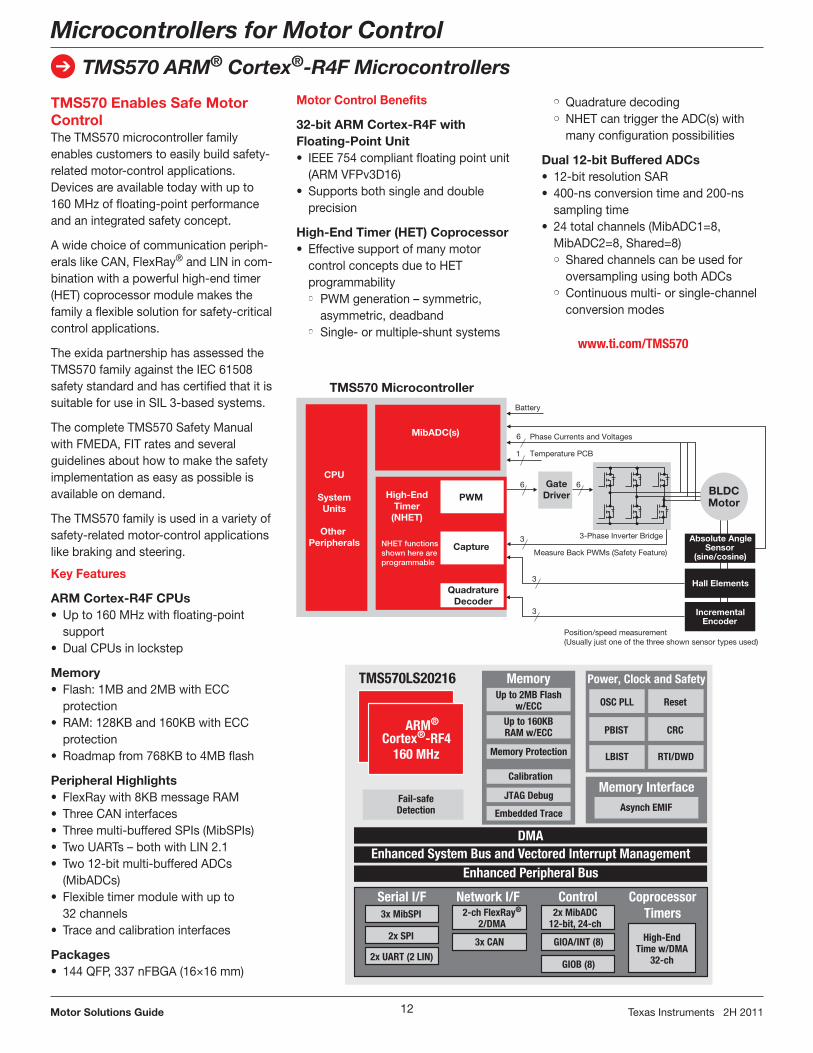
Motor Control Benefits
32-bit ARM Cortex-R4F with Floating-Point Unit• IEEE 754 compliant floating point unit
(ARM VFPv3D16)• Supports both single and double
precision
High-End Timer (HET) Coprocessor• Effective support of many motor
control concepts due to HET programmability• PWM generation – symmetric,
asymmetric, deadband• Single- or multiple-shunt systems
• Quadrature decoding• NHET can trigger the ADC(s) with
many configuration possibilities
Dual 12-bit Buffered ADCs• 12-bit resolution SAR• 400-ns conversion time and 200-ns
sampling time• 24 total channels (MibADC1=8,
MibADC2=8, Shared=8)• Shared channels can be used for
oversampling using both ADCs• Continuous multi- or single-channel
conversion modes
TMS570 Enables Safe Motor ControlThe TMS570 microcontroller family enables customers to easily build safety-related motor-control applications. Devices are available today with up to 160 MHz of floating-point performance and an integrated safety concept.
A wide choice of communication periph-erals like CAN, FlexRay® and LIN in com-bination with a powerful high-end timer (HET) coprocessor module makes the family a flexible solution for safety-critical control applications.
The exida partnership has assessed the TMS570 family against the IEC 61508 safety standard and has certified that it is suitable for use in SIL 3-based systems.
The complete TMS570 Safety Manual with FMEDA, FIT rates and several guidelines about how to make the safety implementation as easy as possible is available on demand.
The TMS570 family is used in a variety of safety-related motor-control applications like braking and steering.
Key Features
ARM Cortex-R4F CPUs• Up to 160 MHz with floating-point
support• Dual CPUs in lockstep
Memory• Flash: 1MB and 2MB with ECC
protection• RAM: 128KB and 160KB with ECC
protection• Roadmap from 768KB to 4MB flash
Peripheral Highlights• FlexRay with 8KB message RAM• Three CAN interfaces• Three multi-buffered SPIs (MibSPIs)• Two UARTs – both with LIN 2.1• Two 12-bit multi-buffered ADCs
(MibADCs)• Flexible timer module with up to
32 channels• Trace and calibration interfaces
Packages• 144 QFP, 337 nFBGA (16×16 mm)
www.ti.com/TMS570
➔
13Motor Solutions Guide Texas Instruments 2H 2011
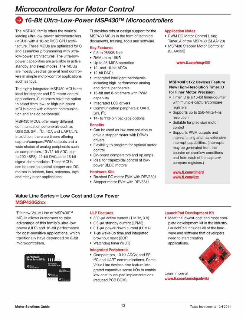
LaunchPad Development Kit• Meet the lowest-cost and most com-
plete develop ment kit in the industry. LaunchPad includes all of the hard-ware and software that developers need to start creating applications.
Learn more at www.ti.com/launchpadwiki
Microcontrollers for Motor Control
16-Bit Ultra-Low-Power MSP430™ Microcontrollers
TI’s new Value Line of MSP430™ MCUs allows customers to take advantage of this family’s ultra-low power (ULP) and 16-bit performance for cost-sensitive applications, which traditionally have depended on 8-bit microcontrollers.
Value Line Series = Low Cost and Low PowerMSP430G2xx
The MSP430 family offers the world’s leading ultra-low-power microcontrollers (MCUs) with a 16-bit RISC CPU archi-tecture. These MCUs are optimized for C and assembler programming with ultra-low-power architectures. The ultra-low-power capabilities are available in active, standby and sleep modes. The MCUs are mostly used as general host control-lers in simple motor-control applications such as toys.
The highly integrated MSP430 MCUs are ideal for stepper and DC-motor-control applications. Customers have the option to select from low- or high-pin-count MCUs along with different communica-tion and analog peripherals.
MSP430 MCUs offer many different communication peripherals such as USB 2.0, SPI, I2C, IrDA and UART/LIN. In addition, there are timers offering capture/compare/PWM outputs and a wide choice of analog peripherals such as comparators, 10-/12-bit ADCs (up to 200 kSPS), 12-bit DACs and 16-bit sigma-delta modules. These MCUs can be used to control stepper and DC motors in printers, fans, antennas, toys and many other applications.
www.ti.com/msp430
MSP430F51x2 Devices Feature New High-Resolution Timer_D for Finer Motor Precision• Timer_D is a 16-bit timer/counter
with multiple capture/compare registers
• Supports up to 256-MHz/4-ns resolution
• Suitable for precision motor control
• Supports PWM outputs and interval timing and has extensive interrupt capabilities. (Interrupts may be generated from the counter on overflow conditions and from each of the capture/compare registers.)
www.ti.com/timerdwww.ti.com/5xx
TI provides robust design support for the MSP430 MCUs in the form of technical documents, training, tools and software.
Key Features• 0.5 to 256KB flash• RAM up to 16KB• Up to 25-MIPS operation• 12- and 10-bit ADCs• 12-bit DACs• Integrated intelligent peripherals
including high-performance analog and digital peripherals
• 16-bit and 8-bit timers with PWM capability
• Integrated LCD drivers• Communication peripherals: UART,
SPI, I2C• 14- to 113-pin package options
Benefits• Can be used as low-cost solution to
drive a stepper motor with DRV8x drivers
• Flexibility to program for optimal motor control
• On-board comparators and op amps• Ideal for trapezoidal control of low-
power BLDC motors
Hardware Kits• Brushed DC motor EVM with DRV8801• Stepper motor EVM with DRV8811
ULP Features• 300-μA active current (1 MHz, 3 V)• 0.5-μA standby current (LPM3)• 0.1-μA power-down current (LPM4)• 1-μs wake-up time and integrated
brownout reset (BOR)• Watchdog timer (WDT)
Integrated Peripherals• Comparators, 10-bit ADCs; and SPI,
I2C and UART communications. Some Value Line devices also feature inte-grated capacitive sense I/Os to enable low-cost touch-pad implementations (reduced PCB BOM).
Application Notes• PWM DC Motor Control Using
Timer_A of the MSP430 (SLAA120)• MSP430 Stepper Motor Controller
(SLAA223)
14Motor Solutions Guide Texas Instruments 2H 2011
➔
Selection Guides
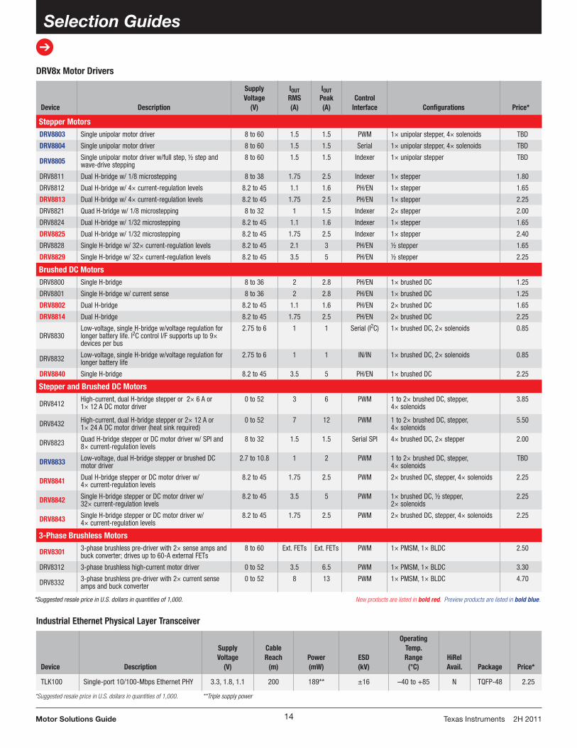
Industrial Ethernet Physical Layer Transceiver
Device Description
Supply Voltage
(V)
Cable Reach
(m)Power (mW)
ESD(kV)
Operating Temp.Range
(°C) HiRel Avail. Package Price*
TLK100 Single-port 10/100-Mbps Ethernet PHY 3.3, 1.8, 1.1 200 189** ±16 –40 to +85 N TQFP-48 2.25
*Suggested resale price in U.S. dollars in quantities of 1,000. **Triple supply power
DRV8x Motor Drivers
Device Description
Supply Voltage
(V)
IOUT RMS (A)
IOUT Peak (A)
Control Interface Configurations Price*
Stepper MotorsDRV8803 Single unipolar motor driver 8 to 60 1.5 1.5 PWM 1× unipolar stepper, 4× solenoids TBD
DRV8804 Single unipolar motor driver 8 to 60 1.5 1.5 Serial 1× unipolar stepper, 4× solenoids TBD
DRV8805 Single unipolar motor driver w/full step, ½ step and wave-drive stepping
8 to 60 1.5 1.5 Indexer 1× unipolar stepper TBD
DRV8811 Dual H-bridge w/ 1/8 microstepping 8 to 38 1.75 2.5 Indexer 1× stepper 1.80
DRV8812 Dual H-bridge w/ 4× current-regulation levels 8.2 to 45 1.1 1.6 PH/EN 1× stepper 1.65
DRV8813 Dual H-bridge w/ 4× current-regulation levels 8.2 to 45 1.75 2.5 PH/EN 1× stepper 2.25
DRV8821 Quad H-bridge w/ 1/8 microstepping 8 to 32 1 1.5 Indexer 2× stepper 2.00
DRV8824 Dual H-bridge w/ 1/32 microstepping 8.2 to 45 1.1 1.6 Indexer 1× stepper 1.65
DRV8825 Dual H-bridge w/ 1/32 microstepping 8.2 to 45 1.75 2.5 Indexer 1× stepper 2.40
DRV8828 Single H-bridge w/ 32× current-regulation levels 8.2 to 45 2.1 3 PH/EN ½ stepper 1.65
DRV8829 Single H-bridge w/ 32× current-regulation levels 8.2 to 45 3.5 5 PH/EN ½ stepper 2.25
Brushed DC MotorsDRV8800 Single H-bridge 8 to 36 2 2.8 PH/EN 1× brushed DC 1.25
DRV8801 Single H-bridge w/ current sense 8 to 36 2 2.8 PH/EN 1× brushed DC 1.25
DRV8802 Dual H-bridge 8.2 to 45 1.1 1.6 PH/EN 2× brushed DC 1.65
DRV8814 Dual H-bridge 8.2 to 45 1.75 2.5 PH/EN 2× brushed DC 2.25
DRV8830Low-voltage, single H-bridge w/voltage regulation for longer battery life. I2C control I/F supports up to 9× devices per bus
2.75 to 6 1 1 Serial (I2C) 1× brushed DC, 2× solenoids 0.85
DRV8832 Low-voltage, single H-bridge w/voltage regulation for longer battery life
2.75 to 6 1 1 IN/IN 1× brushed DC, 2× solenoids 0.85
DRV8840 Single H-bridge 8.2 to 45 3.5 5 PH/EN 1× brushed DC 2.25
Stepper and Brushed DC Motors
DRV8412High-current, dual H-bridge stepper or 2× 6 A or 1× 12 A DC motor driver
0 to 52 3 6 PWM 1 to 2× brushed DC, stepper, 4× solenoids
3.85
DRV8432 High-current, dual H-bridge stepper or 2× 12 A or 1× 24 A DC motor driver (heat sink required)
0 to 52 7 12 PWM 1 to 2× brushed DC, stepper, 4× solenoids
5.50
DRV8823 Quad H-bridge stepper or DC motor driver w/ SPI and 8× current-regulation levels
8 to 32 1.5 1.5 Serial SPI 4× brushed DC, 2× stepper 2.00
DRV8833 Low-voltage, dual H-bridge stepper or brushed DC motor driver
2.7 to 10.8 1 2 PWM 1 to 2× brushed DC, stepper, 4× solenoids
TBD
DRV8841 Dual H-bridge stepper or DC motor driver w/ 4× current-regulation levels
8.2 to 45 1.75 2.5 PWM 2× brushed DC, stepper, 4× solenoids 2.25
DRV8842 Single H-bridge stepper or DC motor driver w/ 32× current-regulation levels
8.2 to 45 3.5 5 PWM 1× brushed DC, ½ stepper, 2× solenoids
2.25
DRV8843 Single H-bridge stepper or DC motor driver w/ 4× current-regulation levels
8.2 to 45 1.75 2.5 PWM 2× brushed DC, stepper, 4× solenoids 2.25
3-Phase Brushless Motors
DRV8301 3-phase brushless pre-driver with 2× sense amps and buck converter; drives up to 60-A external FETs
8 to 60 Ext. FETs Ext. FETs PWM 1× PMSM, 1× BLDC 2.50
DRV8312 3-phase brushless high-current motor driver 0 to 52 3.5 6.5 PWM 1× PMSM, 1× BLDC 3.30
DRV8332 3-phase brushless pre-driver with 2× current sense amps and buck converter
0 to 52 8 13 PWM 1× PMSM, 1× BLDC 4.70
*Suggested resale price in U.S. dollars in quantities of 1,000. New products are listed in bold red. Preview products are listed in bold blue.
➔
15Motor Solutions Guide Texas Instruments 2H 2011
Selection Guides
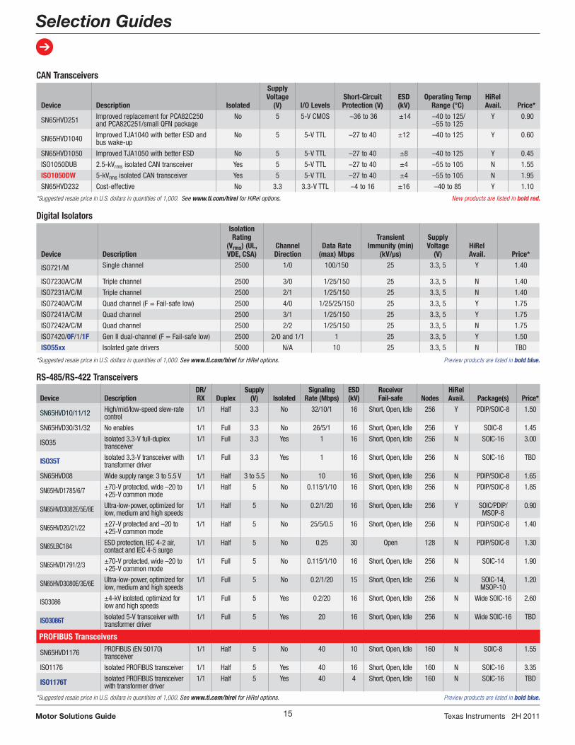
Digital Isolators
Device Description
Isolation Rating
(Vrms) (UL, VDE, CSA)
Channel Direction
Data Rate (max) Mbps
Transient Immunity (min)
(kV/µs)
Supply Voltage
(V)HiRel Avail. Price*
ISO721/M Single channel 2500 1/0 100/150 25 3.3, 5 Y 1.40
ISO7230A/C/M Triple channel 2500 3/0 1/25/150 25 3.3, 5 N 1.40
ISO7231A/C/M Triple channel 2500 2/1 1/25/150 25 3.3, 5 N 1.40
ISO7240A/C/M Quad channel (F = Fail-safe low) 2500 4/0 1/25/25/150 25 3.3, 5 Y 1.75
ISO7241A/C/M Quad channel 2500 3/1 1/25/150 25 3.3, 5 Y 1.75
ISO7242A/C/M Quad channel 2500 2/2 1/25/150 25 3.3, 5 N 1.75
ISO7420/0F/1/1F Gen II dual-channel (F = Fail-safe low) 2500 2/0 and 1/1 1 25 3.3, 5 Y 1.50
ISO55xx Isolated gate drivers 5000 N/A 10 25 3.3, 5 N TBD
*Suggested resale price in U.S. dollars in quantities of 1,000. See www.ti.com/hirel for HiRel options. Preview products are listed in bold blue.
CAN Transceivers
Device Description Isolated
SupplyVoltage
(V) I/O LevelsShort-Circuit Protection (V)
ESD (kV)
Operating Temp Range (°C)
HiRel Avail. Price*
SN65HVD251 Improved replacement for PCA82C250 and PCA82C251/small QFN package
No 5 5-V CMOS –36 to 36 ±14 –40 to 125/ –55 to 125
Y 0.90
SN65HVD1040 Improved TJA1040 with better ESD and bus wake-up
No 5 5-V TTL –27 to 40 ±12 –40 to 125 Y 0.60
SN65HVD1050 Improved TJA1050 with better ESD No 5 5-V TTL –27 to 40 ±8 –40 to 125 Y 0.45
ISO1050DUB 2.5-kVrms isolated CAN transceiver Yes 5 5-V TTL –27 to 40 ±4 –55 to 105 N 1.55
ISO1050DW 5-kVrms isolated CAN transceiver Yes 5 5-V TTL –27 to 40 ±4 –55 to 105 N 1.95
SN65HVD232 Cost-effective No 3.3 3.3-V TTL –4 to 16 ±16 –40 to 85 Y 1.10
*Suggested resale price in U.S. dollars in quantities of 1,000. See www.ti.com/hirel for HiRel options. New products are listed in bold red.
RS-485/RS-422 Transceivers
Device DescriptionDR/RX Duplex
Supply (V) Isolated
Signaling Rate (Mbps)
ESD (kV)
Receiver Fail-safe Nodes
HiRel Avail. Package(s) Price*
SN65HVD10/11/12 High/mid/low-speed slew-rate control
1/1 Half 3.3 No 32/10/1 16 Short, Open, Idle 256 Y PDIP/SOIC-8 1.50
SN65HVD30/31/32 No enables 1/1 Full 3.3 No 26/5/1 16 Short, Open, Idle 256 Y SOIC-8 1.45
ISO35 Isolated 3.3-V full-duplex transceiver
1/1 Full 3.3 Yes 1 16 Short, Open, Idle 256 N SOIC-16 3.00
ISO35T Isolated 3.3-V transceiver with transformer driver
1/1 Full 3.3 Yes 1 16 Short, Open, Idle 256 N SOIC-16 TBD
SN65HVD08 Wide supply range: 3 to 5.5 V 1/1 Half 3 to 5.5 No 10 16 Short, Open, Idle 256 N PDIP/SOIC-8 1.65
SN65HVD1785/6/7 ±70-V protected, wide –20 to +25-V common mode
1/1 Half 5 No 0.115/1/10 16 Short, Open, Idle 256 N PDIP/SOIC-8 1.85
SN65HVD3082E/5E/8E Ultra-low-power, optimized for low, medium and high speeds
1/1 Half 5 No 0.2/1/20 16 Short, Open, Idle 256 Y SOIC/PDIP/MSOP-8
0.90
SN65HVD20/21/22 ±27-V protected and –20 to +25-V common mode
1/1 Half 5 No 25/5/0.5 16 Short, Open, Idle 256 N PDIP/SOIC-8 1.40
SN65LBC184 ESD protection, IEC 4-2 air, contact and IEC 4-5 surge
1/1 Half 5 No 0.25 30 Open 128 N PDIP/SOIC-8 1.30
SN65HVD1791/2/3 ±70-V protected, wide –20 to +25-V common mode
1/1 Full 5 No 0.115/1/10 16 Short, Open, Idle 256 N SOIC-14 1.90
SN65HVD3080E/3E/6E Ultra-low-power, optimized for low, medium and high speeds
1/1 Full 5 No 0.2/1/20 15 Short, Open, Idle 256 N SOIC-14, MSOP-10
1.20
ISO3086 ±4-kV isolated, optimized for low and high speeds
1/1 Full 5 Yes 0.2/20 16 Short, Open, Idle 256 N Wide SOIC-16 2.60
ISO3086T Isolated 5-V transceiver with transformer driver
1/1 Full 5 Yes 20 16 Short, Open, Idle 256 N Wide SOIC-16 TBD
PROFIBUS Transceivers
SN65HVD1176 PROFIBUS (EN 50170) transceiver
1/1 Half 5 No 40 10 Short, Open, Idle 160 N SOIC-8 1.55
ISO1176 Isolated PROFIBUS transceiver 1/1 Half 5 Yes 40 16 Short, Open, Idle 160 N SOIC-16 3.35
ISO1176T Isolated PROFIBUS transceiver with transformer driver
1/1 Half 5 Yes 40 4 Short, Open, Idle 160 N SOIC-16 TBD
*Suggested resale price in U.S. dollars in quantities of 1,000. See www.ti.com/hirel for HiRel options. Preview products are listed in bold blue.

SLYB165C©2011TexasInstrumentsIncorporatedPrintedinU.S.A.by(Printer,City,State)
TI Worldwide Technical Support
InternetTI Semiconductor Product Information Center Home Pagesupport.ti.com
TI E2E™ Community Home Pagee2e.ti.com
Product Information CentersAmericas Phone +1(972)644-5580
Brazil Phone 0800-891-2616
Mexico Phone 0800-670-7544
Fax +1(972)927-6377 Internet/Email support.ti.com/sc/pic/americas.htm
Europe, Middle East, and AfricaPhone EuropeanFreeCall 00800-ASK-TEXAS (0080027583927) International +49(0)8161802121 RussianSupport +7(4)959810701
Note:TheEuropeanFreeCall(TollFree)numberisnotactiveinallcountries.Ifyouhavetechnicaldifficultycallingthefreecallnumber,pleaseusetheinternationalnumberabove.
Fax +(49)(0)8161802045Internet support.ti.com/sc/pic/euro.htmDirectEmail [email protected]
JapanPhone Domestic 0120-92-3326
Fax International +81-3-3344-5317 Domestic 0120-81-0036
Internet/Email International support.ti.com/sc/pic/japan.htm Domestic www.tij.co.jp/pic
AsiaPhone International +91-80-41381665 Domestic Toll-FreeNumber Note:Toll-freenumbersdonotsupport
mobileandIPphones. Australia 1-800-999-084 China 800-820-8682 HongKong 800-96-5941 India 1-800-425-7888 Indonesia 001-803-8861-1006 Korea 080-551-2804 Malaysia 1-800-80-3973 NewZealand 0800-446-934 Philippines 1-800-765-7404 Singapore 800-886-1028 Taiwan 0800-006800 Thailand 001-800-886-0010Fax +8621-23073686Email [email protected]@ti.comInternet support.ti.com/sc/pic/asia.htm
A122010
Important Notice:TheproductsandservicesofTexasInstrumentsIncorporatedanditssubsidiariesdescribedhereinaresoldsubjecttoTI’sstandardtermsandconditionsofsale.CustomersareadvisedtoobtainthemostcurrentandcompleteinformationaboutTIproductsandservicesbeforeplacingorders.TIassumesnoliabilityforapplicationsassistance,customer’sapplicationsorproductdesigns,softwareperformance,orinfringementofpatents.Thepublicationofinformationregardinganyothercompany’sproductsorservicesdoesnotconstituteTI’sapproval,warrantyorendorsementthereof.
Theplatformbar,C2000,C28x,CodeComposerStudio,controlCARD,ControlSuite,Delfino,E2E,MSP430,Piccolo,TMS320C2000andTMS320C28xaretrademarksandStellarisandStellarisWareareregisteredtrademarksofTexasInstruments.ARMandCortexareregisteredtrademarksofARMLimited.FlexRayisaregisteredtrademarkofDaimlerChryslerAG.MATLABandSimulinkareregisteredtrademarksofTheMathworks,Inc.VisSim/EmbeddedControlsDeveloperisatrademarkofVisualSolutionsInc.Allothertrademarksarethepropertyoftheirrespectiveowners.
IMPORTANT NOTICE
Texas Instruments Incorporated and its subsidiaries (TI) reserve the right to make corrections, modifications, enhancements, improvements,and other changes to its products and services at any time and to discontinue any product or service without notice. Customers shouldobtain the latest relevant information before placing orders and should verify that such information is current and complete. All products aresold subject to TI’s terms and conditions of sale supplied at the time of order acknowledgment.
TI warrants performance of its hardware products to the specifications applicable at the time of sale in accordance with TI’s standardwarranty. Testing and other quality control techniques are used to the extent TI deems necessary to support this warranty. Except wheremandated by government requirements, testing of all parameters of each product is not necessarily performed.
TI assumes no liability for applications assistance or customer product design. Customers are responsible for their products andapplications using TI components. To minimize the risks associated with customer products and applications, customers should provideadequate design and operating safeguards.
TI does not warrant or represent that any license, either express or implied, is granted under any TI patent right, copyright, mask work right,or other TI intellectual property right relating to any combination, machine, or process in which TI products or services are used. Informationpublished by TI regarding third-party products or services does not constitute a license from TI to use such products or services or awarranty or endorsement thereof. Use of such information may require a license from a third party under the patents or other intellectualproperty of the third party, or a license from TI under the patents or other intellectual property of TI.
Reproduction of TI information in TI data books or data sheets is permissible only if reproduction is without alteration and is accompaniedby all associated warranties, conditions, limitations, and notices. Reproduction of this information with alteration is an unfair and deceptivebusiness practice. TI is not responsible or liable for such altered documentation. Information of third parties may be subject to additionalrestrictions.
Resale of TI products or services with statements different from or beyond the parameters stated by TI for that product or service voids allexpress and any implied warranties for the associated TI product or service and is an unfair and deceptive business practice. TI is notresponsible or liable for any such statements.
TI products are not authorized for use in safety-critical applications (such as life support) where a failure of the TI product would reasonablybe expected to cause severe personal injury or death, unless officers of the parties have executed an agreement specifically governingsuch use. Buyers represent that they have all necessary expertise in the safety and regulatory ramifications of their applications, andacknowledge and agree that they are solely responsible for all legal, regulatory and safety-related requirements concerning their productsand any use of TI products in such safety-critical applications, notwithstanding any applications-related information or support that may beprovided by TI. Further, Buyers must fully indemnify TI and its representatives against any damages arising out of the use of TI products insuch safety-critical applications.
TI products are neither designed nor intended for use in military/aerospace applications or environments unless the TI products arespecifically designated by TI as military-grade or "enhanced plastic." Only products designated by TI as military-grade meet militaryspecifications. Buyers acknowledge and agree that any such use of TI products which TI has not designated as military-grade is solely atthe Buyer's risk, and that they are solely responsible for compliance with all legal and regulatory requirements in connection with such use.
TI products are neither designed nor intended for use in automotive applications or environments unless the specific TI products aredesignated by TI as compliant with ISO/TS 16949 requirements. Buyers acknowledge and agree that, if they use any non-designatedproducts in automotive applications, TI will not be responsible for any failure to meet such requirements.
Following are URLs where you can obtain information on other Texas Instruments products and application solutions:
Products Applications
Audio www.ti.com/audio Communications and Telecom www.ti.com/communications
Amplifiers amplifier.ti.com Computers and Peripherals www.ti.com/computers
Data Converters dataconverter.ti.com Consumer Electronics www.ti.com/consumer-apps
DLP® Products www.dlp.com Energy and Lighting www.ti.com/energy
DSP dsp.ti.com Industrial www.ti.com/industrial
Clocks and Timers www.ti.com/clocks Medical www.ti.com/medical
Interface interface.ti.com Security www.ti.com/security
Logic logic.ti.com Space, Avionics and Defense www.ti.com/space-avionics-defense
Power Mgmt power.ti.com Transportation and www.ti.com/automotiveAutomotive
Microcontrollers microcontroller.ti.com Video and Imaging www.ti.com/video
RFID www.ti-rfid.com Wireless www.ti.com/wireless-apps
RF/IF and ZigBee® Solutions www.ti.com/lprf
TI E2E Community Home Page e2e.ti.com
Mailing Address: Texas Instruments, Post Office Box 655303, Dallas, Texas 75265Copyright © 2011, Texas Instruments Incorporated