THURGOONA BMS MASTER PLAN - Charles Sturt University€¦ · 4 Section 1 - CSU's Thurgoona BMS:...
19
THURGOONA BMS MASTER PLAN ..............”the way forward” Version No:1.0 | Date: 24 July 2012
Transcript of THURGOONA BMS MASTER PLAN - Charles Sturt University€¦ · 4 Section 1 - CSU's Thurgoona BMS:...

THURGOONA BMS MASTER PLAN
..............”the way forward” Version No:1.0 | Date: 24 July 2012

CHARLES STURT UNIVERSITY THURGOONA BMS MASTER PLAN
July 2012 2 of 19
Table of Contents 1 Purpose of this Document .............................................................................................................. 3
2 The document is divided into 3 sections ........................................................................................ 3
3 Executive Summary ......................................................................................................................... 4
4 Section 1 - CSU's Thurgoona BMS: Historical Review and Current Position ................................... 5
4.1 Introduction ............................................................................................................................ 5
4.2 Historical Legacy Systems ....................................................................................................... 6
4.2.1 Legacy BAS and Associated Mechanical Services ........................................................... 6
4.2.2 Mechanical Services Review ........................................................................................... 8
4.2.3 Siemens BAS Review ....................................................................................................... 9
5 Section 2 - CSU's Thurgoona BMS: BMIS Integration, Functionality and Mechanical Services Solutions ............................................................................................................................................... 12
5.1 Introduction .......................................................................................................................... 12
5.2 BACnet Interoperability ........................................................................................................ 12
5.3 BMIS Integration ................................................................................................................... 12
5.4 BMIS Functionality ................................................................................................................ 13
5.5 Mechanical solutions ............................................................................................................ 13
5.5.1 Introduction .................................................................................................................. 13
5.5.2 Stage 1 – Review, Evaluate and Document Existing Performance ............................... 13
5.5.3 Stage 2 – Design and Upgrade Control Strategy, Plant and Equipment ....................... 14
5.5.4 Stage 3 – Upgrade BAS and Interface with BMIS .......................................................... 14
5.5.5 Recommended Mechanical Services Improvements .................................................... 14
6 Section 3 - CSU's Thurgoona BMS: Future Integration and Extension - Medium and Long Term 15
6.1 Introduction .......................................................................................................................... 15
6.2 Existing BAS ........................................................................................................................... 15
6.2.1 Existing BAS Controllers’ Point List and Budget for Upgrade ....................................... 16
6.3 Summary Recommendations ................................................................................................ 16
6.4 Upgrade Plan Recommendation ........................................................................................... 17
7 Abbreviations Used ....................................................................................................................... 18

CHARLES STURT UNIVERSITY THURGOONA BMS MASTER PLAN
July 2012 3 of 19
1 Purpose of this Document This document was prepared by David Sattler of Sattler Consulting for Charles Sturt University – Division of Facilities Management (DFM) and describes Charles Sturt University’s Thurgoona Building Management Systems (BMS) Master Plan. Enhancing CSU’s achievements in obtaining their sustainability goals and in lessening their impact on the environment, whilst improving services delivery and operational procedures, CSU had identified the need for a BMS Master Plan at Thurgoona. This BMS Master Plan for Thurgoona identifies the strategy for replacement of the existing legacy BMS systems and integration into the BMIS to provide CSU the remote Supervisory Access and Control it requires to operate the building services effectively and efficiently whilst offering remote, University wide access on a single platform. Hence the BMS Master Plan recommends medium and long integration from a historical perspective to the future and outlines the pathway CSU has taken to direct future development which will improve existing service infrastructure. The BMS Master Plan is divided into sections to provide a better understanding of the comprehensive nature of the project and its focus.
2 The document is divided into 3 sections
Section 1 Page 5
• CSU's Thurgoona BMS: Historical Review and Current Position
Section 2 Page 12
• CSU'sThurgoona BMS: BMIS Integration, Functionality and Mechanical Services Solutions
Section 3 Page 15
• CSU's Thurgoona BMS: Future Integration and Extension - Medium and Long Term

CHARLES STURT UNIVERSITY THURGOONA BMS MASTER PLAN
July 2012 4 of 19
3 Executive Summary Sattler Consulting Pty Ltd was commissioned by Charles Sturt University to develop a Building Management System (BMS) Master Plan. The Master Plan is intended to outline CSU’s pathways and strategies to improve building control at Thurgoona as an important component of DFM’s vision for a holistic approach to Facilities Management at CSU. This vision involves managing facilities using a ‘life cycle’ approach to maintain the functionality and performance of the asset throughout its life. This Master Plan identifies significant building systems that are approaching end of life and allows DFM to replace them in a planned manner rather than waiting until they fail and cause disruption or poor environmental performance for the building occupants. With the opportunities afforded through current networking of building systems not only will operators be able to have Remote Supervisory Access and Control of Thurgoona buildings across the CSU network they will also be able to manage energy thus curtailing costs. This in turn will enable CSU to run its buildings both effectively and efficiently – effectively in terms of streamlining maintenance work and providing optimal thermal comfort and efficiently in terms of minimising energy use and occupant satisfaction; hence aiding in CSU achieving its environmental sustainabilty goals with an associated CO2 greenhouse impact reduction. It is expected that integrating Thurgoona’s legacy BMS can: reduce the daily involvement of some campus operations personnel by 10-20% via
automatic operation – Greater efficiency increase the life cycle of equipment – Reducing costs provide better air-conditioning related conditions – Greater effectiveness and less potential
waste of energy consumption improve access to controls – Improved operation improve climate control for building occupants – Improved client satisfaction
CSU has accomplished a large portion of the systems integration target and has commenced energy management and savings at Thurgoona as part of the new buildings constructed which has included the integration of several legacy systems. This Master Plan will benchmark the future integration of the hoarier systems.
Final integration of all BMS at Thurgoona will result in more holistic and
synergistic facility management at Thurgoona with improved conditions and reduced energy consumption

CHARLES STURT UNIVERSITY THURGOONA BMS MASTER PLAN
July 2012 5 of 19
4 Section 1 - CSU's Thurgoona BMS: Historical Review and Current Position
To continue CSU’s vision for an integrated, computerised tool on a single platform assisting in meeting CSU’s requirements for greater efficiencies, improved effectiveness, improved client comfort and reduced costs, the Thurgoona BMS Master Plan was developed. The Master Plan shows the historical pathway, current achievements, and future legacy systems integration with a medium to long term future view.
CSU continues with utilisation of Open Protocol Building Automation and Control Systems at the Thurgoona campus to provide the tools necessary to manage and reduce their operating and maintenance costs. The Master Plan will lead to the integration of the remaining legacy systems using Open Protocol Communications. This Plan will provide the guidelines for CSU’s budgetary and planning for historical systems integration at Thurgoona.
4.1 Introduction
The aim of this Plan is to outline the procedures and strategies required by CSU to move it in the direction of having an integrated approach to building controls management with synergistic Facility Management at the Thurgoona campus as a continuation of systems’ integration University wide. Improved operation and facility management via a single platform interface will bring the legacy systems into the present 2012 technologies. This in turn will enable CSU to run its buildings both more effectively and efficiently – effectively in terms of streamlining maintenance work and similar procedures and efficiently in terms of providing optimal thermal comfort and minimising energy use.
Currently the Thurgoona campus has several legacy systems from different manufacturers that are not integrated to the BMIS. This Master Plan identifies the strategy for integrating the existing BMS systems to provide CSU with the means to operate the building services effectively and efficiently whilst offering remote access.
Hence the BMIS Master Plan is a prescient document to direct future development whilst reporting on historical achievements.
The purpose of this strategy is to document for Charles Sturt University (CSU) a Building Management System (BMS) Master Plan specifically for Thurgoona based buildings on the University-wide BMIS Master Plan. The plan will serve to continue the University’s development of a comprehensive Single Platform Control and Data Management System for building services across all campuses. The Master Plan will mould all systems into the BMIS adding to the integrated common platform for Local and Remote Supervisory Access and Control.

CHARLES STURT UNIVERSITY THURGOONA BMS MASTER PLAN
July 2012 6 of 19
4.2 Historical Legacy Systems Over recent years Thurgoona campus has undergone improvements with new construction and retrofits of existing stock. Each building and retrofit is designed to provide improved services, upgrade redundant systems and provide a more sustainable outcome. Each new and retrofitted building has incorporated new Open Protocol automatic control systems that have been optimised and integrated into the BMIS. This provides remote access via a single platform interface with shared data using BACnet as the Open Protocol for integration and communication. The following buildings are the remaining non-integrated legacy systems that require updating for amalgamation into the BMIS.
Project Project Description Campus BAS/Control
System
BMIS Integration as of Jan
2012 1 Building 750:
Lecture Theatre Thurgoona Siemens Apogee BAS No
2 Building 752: Student Union Thurgoona Siemens Apogee
BAS No
3 Building 760: Office Building Thurgoona Siemens Apogee
BAS No
4 Building 761: Teaching Building Thurgoona Siemens Apogee
BAS No
5 Building 762: Herbarium Thurgoona Siemens Apogee
BAS No
6 Building 763: Murray School of Education Thurgoona Siemens Apogee
BAS No
7 Cottages Thurgoona Siemens Apogee BAS No
These systems were installed during the early building construction phase of the campus from1996 until DFM adopted a design standard that required an open protocol to be used in any new construction and hence these buildings represent the legacy systems. 4.2.1 Legacy BAS and Associated Mechanical Services
Siemens proprietary systems were installed as part of the respective building construction projects. These BAS are a combination of automatic controls connected to a BAS front end for access to the data, information and for Remote Supervisory Access and Control. The systems use a proprietary communication protocol and in its present state are unavailable for integration into the BMIS.
The current controls installed are the MCC Powers brand of Siemens controls with an Apogee front end PC. The MCC Powers controls were originally developed in the 1980’s and since utilised throughout the world. The Apogee front end provides the interface to the controls for editing, graphics, trending, events, graphing, point definition, and other functions.
Previously, historical construction practices and poor operational guidelines post construction resulted in the BAS not being implemented nor operated as required, resulting in numerous

CHARLES STURT UNIVERSITY THURGOONA BMS MASTER PLAN
July 2012 7 of 19
problems and issues with the system/controls. So poor were the operational guidelines of the system that previous management operated the mechanical services in manual, an approach that ultimately meant that the system faults were not detected and the systems were run inefficiently; compounding the issues that contributed to poor comfort and energy performance. There were also mechanical and electrical issues that required resolution summarised as follows.
• Valves installed backwards (operating in reverse to flow) • Sensors installed in incorrect locations and hence not accurately reading temperature
(mainly pipe sensors and some zone sensors) • Pipes not connected • Mechanical systems not implemented or not commissioned • Pumps operating in reverse • BAS communication installed in cable trays with 240 voltage • Over 100+ list of problems with the Siemens BAS • Can only use previous version of software (had to step back a version) due to licensing issues • License for only 2 users to access the BAS at one time • Labelling substandard (sticky labels that have peeled off) • BAS and controller wiring substandard
The controls during construction were installed by a contractor of Siemens and this led to many inconsistencies and anomalies that took years to resolve.
The Siemens system operation has improved since DFM’s operational staff has rectified many problems and inculcated Siemens to improve the system via a service contract. The current operational problems that exist are minimal; however it was noticed many inconsistencies with the system, graphics and points (refer Siemens BAS Review Section5.2.3); hence reducing its operating effectiveness.
The current version of these controls (controllers used locally to operate the plant and equipment) cannot operate using the BACnet Open Communication Protocol due to their age – they were developed before BACnet communications was designed using the MCC Powers proprietary communications protocol. The Apogee BAS software version currently installed is not BACnet and hence would require upgrade to be BACnet compliant. If the Apogee was updated to be BACnet compliant, the communication from the Apogee to the controllers would remain as proprietary. Siemens will not allow access into the BMS as required by CSU. Recently the PC has been upgraded, however it is operating under Windows Server 2003 and the PC has minimal amounts of memory and hard disk storage.
The controllers that manage the equipment within the building are obsolete and there are few if any spares available in Australia. This puts CSU in a risk condition whereby if a controller fails then the services cannot operate automatically and thus comfort conditions may not be maintainable. If a replacement cannot be found then a new style controller may be compatible; however the front end software will have to be updated and the system will be a conglomeration of new and old controllers, making service more difficult. Currently the service with old controllers and software is more difficult and time consuming – hence maintenance costs are higher. Also this campus is the only remaining one that has Siemens controllers and hence CSU cannot benefit from a more wholesale approach to a service contract (across all campuses).
A summary of the current controls and BMS is as follows.
• Current system is inadequate for its purpose

CHARLES STURT UNIVERSITY THURGOONA BMS MASTER PLAN
July 2012 8 of 19
• Spares are not available • Not maintainable • Obsolete controls • Difficult to use • SBT only provide very limited access to the BMS • Cannot fit into CSU’s BMIS and BACnet plan • Communications unreliable and intermittent • System time-consuming to use and navigate • Lack of commitment and support from manufacturer and installer • Manufacturer/distributor not represented extensively in Thurgoona
The Apogee BMS and associated controllers and controls do not comply with CSU’s BMIS Master Plan and therefore leaves CSU in a risk adverse situation in providing required temperature conditions and associated services.
4.2.2 Mechanical Services Review
It is clear from our site inspection, discussions and observations that improvements to the buildings cooling systems are essential to achieve client comfort levels within appropriate standards. This will require a substantial body of work to determine a way forward and to achieve the physical changes that are required. The following are general observations of site issues.
In terms of cooling systems, the buildings that utilise natural ventilation do not appear to manage the heat load efficaciously. Therefore limited cooling capacity combined with antiquated controls is the major impediments to meeting peak summer comfort conditions and serving CSU’s facility management needs.
An earlier design approach to supplement the night purge was a proposal to install geothermal loops and in one case a cooling loop to the nearby wetland areas. Some of the buildings were made ready for these connections though the systems were not fully implemented, except for a loop under building 751, C.D. Blake Theatre. Other installations are limited to manifolds, valves and pipe work within the buildings.
Another early approach for supplementary cooling was that three of the buildings, being 672- Old Pavilion, 751-Gums Cafe and 752- C.D. Blake Theatre, had misting systems installed though these systems were not brought into service due to system control and health concerns as the water source was harvested rain water.
In terms of heating systems, winter comfort conditions can generally be met. The bulk of the heating is from solar systems and supplementary gas fired boilers. Due to the age of the mechanical services, some solar panels and other equipment require replacement and refurbishment. The solar panels appear to have plexi-glass covers and they seem to be sun damaged reducing their effectiveness. One solar panel is broken and needs replacement however these panels are old technology and cannot be replaced one for one. Rather, the entire building sets need to be replaced.
An important observation about the hydraulic construction of the mechanical services is that the installations are of a poor quality, evident by poor labelling, poor insulation, lack of corrosion prevention, lack of accurate as built diagrams and poor placement of sensors. These shortfalls will require upgrade, replacement or simplification of elements of the hydraulic systems.

CHARLES STURT UNIVERSITY THURGOONA BMS MASTER PLAN
July 2012 9 of 19
In summary then, offices and teaching spaces that do not have supplementary cooling systems have inadequate cooling during the peak summer temperatures. Winter conditions are generally met via the heating systems but those systems are at the end of their operational lives. Supplementary systems are generally not integrated and can fight one another and, finally, the systems themselves generally require improved hydraulic installation.
4.2.3 Siemens BAS Review
Recently Sattler Consulting conducted a review of the Siemens BMS from the following perspectives. The system was reviewed via the Apogee front end and a building by building controls review in conjunction with examining the mechanical services.
• Consistency with Graphics • Implementation of controls • Installation of controllers, cabinets, wiring • Sensor location and installation • Mechanical services installation and configuration • Electrical/Mechanical services installation • Operation of mechanical services • Review of trends • Review of O&M manuals
The following was observed during the above reviews.
4.2.3.1 BAS AND CONTROLS SERVICES REVIEW The controls installation is not to standard. The pipe sensors were not installed in accordance with standards for accurate measurement – all controls rely on the sensors and if the sensors are not accurate then the mechanical services will operate incorrectly and inefficiently and/or not provide required temperature conditions. Controls labelling is deficient.
4.2.3.2 COTTAGES REVIEW
• In general according to the sensors on the graphics, the system appears to be maintaining setpoint, however when there are several hot days the building structure absorbs the heat and hence the system becomes out of control and cannot maintain setpoint
• Solar graphic: not clear in diagrammatic view – appears the tanks have water in from 2 locations but no water out – needs to be more clearer
• Cottage 6 was not operating correctly: Room Temperature was 22.56°C with a Day Setpoint of 22.0°C. The window and roof louvers should be opening; however they were shut at 0%.
4.2.3.3 BUILDING 750 LECTURE THEATRE REVIEW
• Auditorium CO2 level requires calibration as it reads high constantly at 969.25 with a setpoint of 700. The trends confirm that the levels are close to the limits (even outside occupancy hours) as per ASHRAE’s standards (refer Appendix A for more information).
• Graphics point for heating/cooling valve % open is a “HBZ1V” point and is not consistent with other similar points.

CHARLES STURT UNIVERSITY THURGOONA BMS MASTER PLAN
July 2012 10 of 19
• Stage fan setpoint was 22.00°C and stage fan was off when room temperature was 23.10°C • Foyer cooling demand is 72%, foyer setpoint was 21.00°C but there is no indication of the
foyer zone temperature • Many points not on trend • Global information: average temperature is average of what? • Solar panel temperature reads 195°C – error • Need to show difference in temperature (supply and return) of geothermal grid to show
performance – CSU personnel are not sure if it is working
4.2.3.4 BUILDING 752 STUDENT UNION REVIEW
• Many points not on trend • Room temperature setpoint is wrong point on graphics – it is equal to OAT. Is it incorrect in
PPCL code as well? • Fan reversing switch – Graphics says : “On=cool, On=heat” – this is confusing – make it
simple “cooling” (when in on state) and “heating” (when in off state) • Level 3 graphic has no information on it – is it incomplete?
4.2.3.5 BUILDING 760 OFFICE BUILDING REVIEW
• Many points not on trend • Maximum heating demand shows 0.40% is this 40% or less than 1%, constantly switches
(flashes) between 31% then 96% and 0.4% • Heating flow diagram is confusing • Heating pump enable off and status on • Heating circuit reads 24.01°C and 88.93°C in the same circuit • Valve point not reading “OLAKMX” (not found in database when checked) • Floor plans do not show setpoints
4.2.3.6 BUILDING 761 TEACHING BUILDING REVIEW
• Many points not on trend • “East Zone Cooling Demand” and “West Zone Cooling Demand” are the same point on the
graphic • “East Cooling Valve” and “West Cooling Valve” – actual points are “Louvers” • Appears the cooling cycle is not working • Heating plant graphics confusing, incomplete and very basic • Heating system shows 23.78°C and 45.06°C, second temperature may be solar but there is
no description on graphic • Floor plans do not have setpoints
4.2.3.7 BUILDING 762 HERBARIUM REVIEW
• Many points not on trend

CHARLES STURT UNIVERSITY THURGOONA BMS MASTER PLAN
July 2012 11 of 19
• Level 1 has 2 sensors close to each other – why? • “Compactors temperature (and setpoint and humidity)” incorrect point or text on graphic –
should be “demands” – all show XX percent not correct values • AC filter blocked – says “On/Off” should be “Normal” or “Alarm or Fault” • Compactus graphic: • Return temperature on trend shows 21.35°C from 14-8 to 12-10 2011 (no change) then after
changes as per real measurement • Heating Plant • Temperature sensor – error reads -40°C • Other temperature sensors show on (in green) • Boiler operation not energy efficient: • OAT is 24.5°C, heating tank temperature is 47.17°C, boiler enable is on, status off and leaving
water temperature is 21.72°C • Valve shows 0 volts rather than % open • Solar pump came on to heat tank but solar sensor is disabled • A 3 way valve connects to a 3 way valve – graphic confusing • No setpoints on floor plans • Louvre graphics confusing: actuators are drive open, drive close, however status says
“On/Off” for Open and “On/Off” for closed
4.2.3.8 BUILDING 763 MURRAY SCHOOL OF EDUCATION REVIEW
• Many points not on trend • Level 1 South East temperature sensor is 34.39°C, average room temperature is 22.15°C –
therefore what is the average of? • No setpoints on floor plans • Slab Heating North • Roof Slab temperature: 23.78°C, sensor to slab: 28.83°C, sensor to pipe out of roof slab is
(and leve 1&2 slabs): 25.84°C and sensor across valve before this is 27.33°C (boiler leaving temperature), level 1 slab: 21.51°C, level G slab: 21.31°C, north tank temperature 45°C, pumps and boiler are off. Average Room Temperature is level 1 north: 22.38°C, ground north: 21.97°C. It appears that sensors are not reading correctly and the heating system is working when it should not be
• Slab Heating South • Pumps on – why?, average level 1 south room temperature: 22.15°C, ground south
temperature: 21.82°C, tank 46.42°C, OAT: 26.43°C – the system appears to be operating when not required
• Temperature sensor past boiler bypass valve is not working • Bypass to roof slab (supply and return) and level 1 slab is open to 50% - not correct

CHARLES STURT UNIVERSITY THURGOONA BMS MASTER PLAN
July 2012 12 of 19
5 Section 2 - CSU's Thurgoona BMS: BMIS Integration, Functionality and Mechanical Services Solutions
5.1 Introduction
BMIS is an integration of multiple BAS systems and interconnection between other facility management systems for database utilisation and information sharing all via a single platform.
Integrating the legacy systems requires a gateway or interface to operate on a single platform. Other integrated systems utilise the BACnet protocol, chosen by CSU to be the Open Protocol communication for the BMIS.
Therefore the BMIS integrates all BMS and BAS systems via BACnet allowing for access via the single platform.
5.2 BACnet Interoperability The BMIS uses the BACnet communication protocol to integrate the various BAS and BMS into the single platform. The BMIS represents all data, points and information on the single platform allowing Remote Supervisory Access and Control of the building services operated by the controls systems. The BMIS integration tool utilises BACnet to scan the CSU network and pull up the point information and data of all the controls. The BMIS then displays the information via the user interface. The BMIS provides access and ability to control points through the use of the BACnet protocol.
Without the ability to communicate via BACnet, systems cannot be easily or fully integrated into the BMIS.
Therefore it is a requirement that all systems utilise BACnet for BMIS integration to ensure a complete fully functional amalgamation providing all the necessary data and information for facility functionality.
5.3 BMIS Integration The Legacy BAS are not capable of communicating or integrating with the BMIS in their present state. The Apogee BMS front end may possibly be upgraded to the BACnet version, however there will be various costs involved and much configuration to expose the BACnet objects to the BMIS and upgrading of the existing Apogee. The existing controllers cannot communicate with BACnet as they were designed and manufactured before BACnet was available.
The Legacy systems require significant modification for integration via BACnet. The system is composed of the Apogee BMS front end PC that is the user interface for the controllers located in the field controlling the building services attached. The controllers are physically connected to the legacy BMS via a proprietary protocol and wiring (there is direct wiring to the BMS and some use of the CSU network). Since the controllers do not communicate using BACnet and since the legacy BMS is not using BACnet either as a Gateway or as means to interface with the field controllers; the BMIS cannot access the controllers or the BMS.

CHARLES STURT UNIVERSITY THURGOONA BMS MASTER PLAN
July 2012 13 of 19
5.4 BMIS Functionality
The BMIS strength is integration of multiple systems into a single platform. A complete and thorough integration of all BMS and controllers is required for the BMIS to give CSU facility functionality and remote supervisory access and control of the building services including retention and user access to data and information.
Currently the BMIS can read information directly from the controllers and provide this information to the user across the CSU network. The user can also operate equipment from this interface. The interface is seamless and the user does not need to know what “BAS system” they are accessing, only the operation via the user interface to control the building services involved.
For the interface to be seamless the BACnet protocol is required for integration. The BACnet protocol is the most widely used Open Protocol for communication in worldwide applications of BAS. Utilising this protocol provides CSU multiple options for integration from multiple providers whilst providing future proofing. The BACnet allows CSU to have (almost) plug and play controllers from any BACnet compliant devices.
The BMIS project has achieved integration of over 25 BAS to date. The next stage is for legacy systems to be integrated.
5.5 Mechanical solutions
5.5.1 Introduction
The mechanical systems in the legacy buildings utilise natural ventilation with some split type unit air-conditioners. The split units were installed as supplementary air-conditioning due to the inability of the natural ventilation system to manage the heat load. The natural ventilation systems installed should be investigated to determine if they can be modified to provide additional cooling and help meet the heat loads. It is noted that the heating system is satisfactory.
The natural ventilation design has merit, however it requires significant intervention to provide satisfactory temperature conditions and energy efficiency (the initial reason behind natural ventilation design).
A suggested plan to resolve these issues is as follows.
5.5.2 Stage 1 – Review, Evaluate and Document Existing Performance
Stage 1 consists of CSU engaging contractors to thoroughly review the installed systems (natural ventilation) with a specialist mechanical and controls consultant to analyse the systems and their capability, faults and operation. The review would include developing CAD drawings of the system and its subsequent parts.
The review will include introducing pressure test points, testing water flows, measuring accurately the temperature differentials, investigating the actual water runs including the geo-thermal unit, checking if adequate air flows are present, and conducting thermal modelling to obtain a more accurate depiction of the heat loads, confirming the accuracy of the temperature sensors installed.

CHARLES STURT UNIVERSITY THURGOONA BMS MASTER PLAN
July 2012 14 of 19
Included in this review should be the analysis of all sensors, locations, existing installation and functionality to provide accurate and repeatability of data. Options for remedy of sensor and control issues should be included.
The review should include recommendations for additional mechanical services to serve the required heat loads. It is recommended that energy modelling be conducted on the buildings to develop the correct heat load analysis before designing supplementary mechanical services.
Out of this review will be a report and CAD drawings showing the efficacy of the systems and its limitations.
5.5.3 Stage 2 – Design and Upgrade Control Strategy, Plant and Equipment
Stage 2 consists of resolving mechanical services inherent faults in a cost effective and timely manner.
The natural ventilation systems can be assisted to be more effective, whilst still being energy efficient.
With these “base cooling systems” the majority of the cooling systems are installed may possibly be upgraded to meet the loads.
It is apparent that supplementary systems are required to provide adequate management of the heating/cooling loads. Reviewing the current loads and requirements of the buildings is necessary to understand what is required for each building and space.
It is recommended a further detailed review be conducted to ensure existing systems are working, sensors are operational, and heating/cooling loads are examined.
5.5.4 Stage 3 – Upgrade BAS and Interface with BMIS
Stage 3 consists of providing a more accurate and current BAS with integration into the BMIS. The improved and current technology with advanced sensor installation will allow the upgraded systems to be operated efficiently and effectively thus improving CSU’s provision of mechanical services. The upgraded and integrated BAS will allow the system to be constantly “modelled” for operational enhancement.
The systems (mechanical and BAS) should be reviewed (similar to previous utilisation of an Independent Commissioning Agent for other projects at CSU) for a 12 month period ensuring required operation meeting the heat loads and retaining energy efficiency.
5.5.5 Recommended Mechanical Services Improvements
For CSU to optimise the performance of its existing buildings it is essential that a thorough review of the mechanical services be completed as an integrated approach to the implementation of the recommendations contained in the BMIS/BMS Master Plan. In relationship to some buildings this is a substantial body of work that should not be under estimated.
As an adjunct it is recommend the controls be upgraded and integrated into the BMIS to provide enhanced operation and more accurate monitoring for optimal control and energy efficiency. Integrating the mechanical services with the lighting provides the best opportunity to minimise the energy usage – operate the services only when occupied (and including operating lighting when natural lighting is not adequate in conjunction).

CHARLES STURT UNIVERSITY THURGOONA BMS MASTER PLAN
July 2012 15 of 19
6 Section 3 - CSU's Thurgoona BMS: Future Integration and Extension - Medium and Long Term
6.1 Introduction
In their present state, the legacy BAS are not BACnet compliant thus they cannot be integrated into the BMIS.
As part of CSU’s BMIS Master Plan, the next stage is to integrate Thurgoona’s legacy systems (Refer 5.2 Historical Legacy Systems) into the BMIS.
In order to recommend a plan for CSU to budget the upgrades into their financial program, the existing BAS were thoroughly reviewed and each control panel’s point information was extracted to determine a budget estimate.
It is envisaged that a staged plan be instigated for upgrade to match CSU’s budgetary requirements.
6.2 Existing BAS
The existing BAS were reviewed for upgrade to BACnet compliance for integration into the BMIS. The BAS front end software Apogee can be upgraded to be BACnet compliant. In order for this to occur the following also has to form part of the upgrade.
• Upgrade the BAS PC – so it can handle the additional traffic of converting all points and information to BACnet
• Upgrade the operating system to the latest version • Install the BACnet version of software • Expose all points and information as BACnet • Assist BMIS integrator for integration of all BACnet objects and information • Re-commission BAS • Modification of the operational strategies to improve equipment efficiencies and
effectiveness • 12 month warranty
The estimated budget cost for the above work is approximately $50,000.
The local controllers are not BACnet and are older 1980’s design communicating using proprietary communications. The controllers and associated parts are very difficult to obtain should any require repair or fail. These two situations put CSU at risk.
The first risk is the controllers not being BACnet – the integration to the BMIS would be as a Gateway at the BAS PC end. If this communication is lost, then all BACnet operability is lost; whereby if the controllers were individually connected to the BMIS, then if one controller fails, only a small part of the system is compromised – and if they are BACnet it is easier to replace than the existing.

CHARLES STURT UNIVERSITY THURGOONA BMS MASTER PLAN
July 2012 16 of 19
The second risk is the controllers are very old style originally designed 15+ years ago. The parts are extremely difficult to obtain and the systems in their present state are difficult to maintain. Therefore should a controller fail, a replacement may not be available. This puts CSU in a risk situation to provide appropriate and required services to the clientele.
The controllers being of an older style are not as accurate or as easily manageable as the current range of controllers.
6.2.1 Existing BAS Controllers’ Point List and Budget for Upgrade
The individual controllers (or nodes as termed by BAS) were assessed to determine the estimated budget costs for upgrading these controllers to new BACnet controllers.
Total Points all Nodes Node 1 Node 2 Node 3 Node 4 Total Point per Node 355 400 147 232 1,134 Upgrade/Building $230,750 $260,000 $95,550 $150,800 $737,100
Also the individual buildings were reviewed to provide a budget estimate on a building by building basis. The summary is as below.
Building 750 752 760 761 762 763 Cottages Total Point Totals 269 165 143 76 94 241 146 1,134 Upgrade/Building $174,850 $107,250 $92,950 $49,400 $61,100 $156,650 $94,900 $737,100
The upgrade would have to take into account the building and node simultaneously since changing out a node can affect more than one building.
The budget estimate does not allow for contingency or recommended improvement of the sensors, re-calibration of controller sensors and accessories installed in pipework or associated mechanical repairs/modifications.
6.3 Summary Recommendations
As apparent to the above risks and costs to only partially integrate the existing BAS into the BMIS, it is recommended that CSU consider a roll out replacement of the existing BAS with new BACnet compliant controllers and controls. Making use of the above estimated $50,000 towards new BAS is more cost effective than utilising this money to patch up an older system. The combined existing risks are not supportive to CSU and thus inhibit its vision for integrated facility management.
A tender complete with specification and associated documentation provided to the CSU BMS providers for obtaining a cost of works (with rollout schedule) should include the EMS system upgrades and modifications.
CHARLES STURT UNIVERSITY THURGOONA BMS MASTER PLAN
July 2012 17 of 19
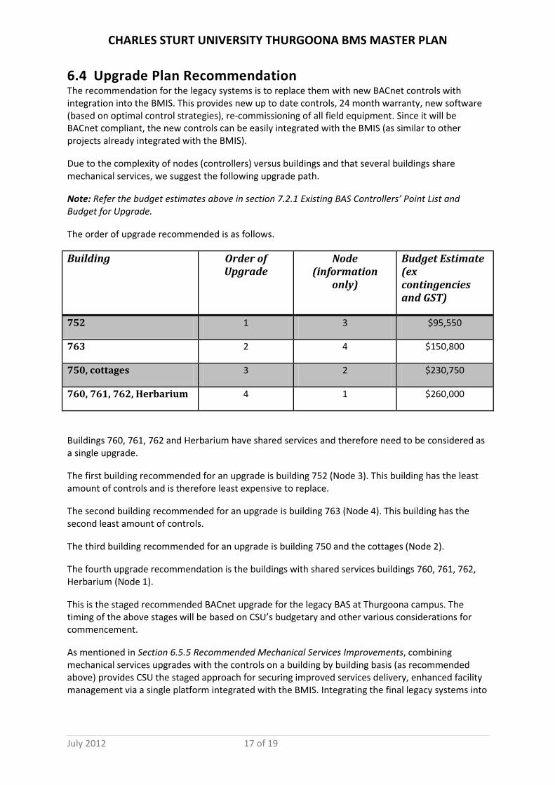
6.4 Upgrade Plan Recommendation The recommendation for the legacy systems is to replace them with new BACnet controls with integration into the BMIS. This provides new up to date controls, 24 month warranty, new software (based on optimal control strategies), re-commissioning of all field equipment. Since it will be BACnet compliant, the new controls can be easily integrated with the BMIS (as similar to other projects already integrated with the BMIS).
Due to the complexity of nodes (controllers) versus buildings and that several buildings share mechanical services, we suggest the following upgrade path.
Note: Refer the budget estimates above in section 7.2.1 Existing BAS Controllers’ Point List and Budget for Upgrade.
The order of upgrade recommended is as follows.
Building Order of Upgrade
Node (information
only)
Budget Estimate (ex contingencies and GST)
752 1 3 $95,550
763 2 4 $150,800
750, cottages 3 2 $230,750
760, 761, 762, Herbarium 4 1 $260,000
Buildings 760, 761, 762 and Herbarium have shared services and therefore need to be considered as a single upgrade.
The first building recommended for an upgrade is building 752 (Node 3). This building has the least amount of controls and is therefore least expensive to replace.
The second building recommended for an upgrade is building 763 (Node 4). This building has the second least amount of controls.
The third building recommended for an upgrade is building 750 and the cottages (Node 2).
The fourth upgrade recommendation is the buildings with shared services buildings 760, 761, 762, Herbarium (Node 1).
This is the staged recommended BACnet upgrade for the legacy BAS at Thurgoona campus. The timing of the above stages will be based on CSU’s budgetary and other various considerations for commencement.
As mentioned in Section 6.5.5 Recommended Mechanical Services Improvements, combining mechanical services upgrades with the controls on a building by building basis (as recommended above) provides CSU the staged approach for securing improved services delivery, enhanced facility management via a single platform integrated with the BMIS. Integrating the final legacy systems into

CHARLES STURT UNIVERSITY THURGOONA BMS MASTER PLAN
July 2012 18 of 19
Thurgoona will result in a holistic and synergistic amalgamation of facility management services at CSU.
7 Abbreviations Used
Abbreviation/Acronym Description/Definition ASHRAE American Society of Heating Refrigeration and Air-conditioning
Engineers BACnet Building Automation Control Network – Open protocol for controls
communication BACnet Device BACnet compliant controls equipment as defined by BACnet standard
and BTL listed BAS Building Automation System BIBB BACnet Interoperability Building Blocks BMIS Building Management and Information System BMS Building Management System BTL BACnet Testing Laboratory where BACnet devices are tested for
conformance DDC Controls Direct Digital Controls (older controls were electronic or pneumatic) EMS Energy Management System LAN Local Area Network MS/TP BACnet Communications Standard: Master Slave/Token Passing
Network CSU’s ITS network
NBS Networked Building Systems Objects BACnet objects as defined by BACnet standard OPC Microsoft Open Connectivity via Open Standards Protocol
PICs BACnet Standard Protocol Implementation Conformance Statement – Stated manufacturer’s compliance to BACnet standard
VSD Variable Speed Drive WAN Wide Area Network

CHARLES STURT UNIVERSITY THURGOONA BMS MASTER PLAN
July 2012 19 of 19
8 Appendix A – CO2 Recommendations
CO2 recommendations from:
Indoor air quality includes
• temperature • odor • high or low levels of gases
Since CO2 is exhaled by people at predictable levels the content of Carbon Dioxide - CO2 - in air may be a significant indication of air quality.
A measure of CO2 indicates the amount of fresh air supply:
• 15 cfm ventilation rate per occupant corresponds to 1000 ppm CO2 • 20 cfm ventilation rate per occupant corresponds to 800 ppm CO2
Normal CO2 Levels
The effects of increased CO2 levels on adults at good health can be summarized:
• normal outdoor level: 350 - 450 ppm • acceptable levels: < 600 ppm • complaints of stiffness and odors: 600 - 1000 ppm • ASHRAE and OSHA standards: 1000 ppm • general drowsiness: 1000 - 2500 ppm • adverse health effects expected: 2500 - 5000 ppm • maximum allowed concentration within a 8 hour working period: 5000 ppm
The levels above are quite normal and maximum levels may occasionally happen from time to time.
Extreme and Dangerous CO2 Levels
• slightly intoxicating, breathing and pulse rate increase, nausea: 30,000 ppm • above plus headaches and sight impairment: 50,000 ppm • unconscious, further exposure death: 100.000 ppm
Carbon Dioxide Standard Levels
The recommendation in ASHRAE standard 62-1989 are
• classrooms and conference rooms 15 cfm per occupant • office space and restaurants 20 cfm per occupant • hospitals 25 cfm per occupant