Thunder Laser Users Manual
41
Transcript of Thunder Laser Users Manual

CONTENTS 1. Preface .................................................................................................................... 1
2. Overview ................................................................................................................. 2
2.1 Brief Introduction............................................................................................ 2
2.2 How the Controller Works .............................................................................. 2
3. Mounting Dimension .............................................................................................. 3
3.1 Dimension of Main Board: .............................................................................. 3
3.2 Dimension of Display: .................................................................................... 3
4. Interface of Main Board .......................................................................................... 4
5. How to Connect the 24V DC to the Controller ...................................................... 6
6. How to Connect the Display .................................................................................. 7
7. How to Connect the Laser Power Supply ............................................................. 9
7.1 TTL- ............................................................................................................... 9
7.2 TTL+ ............................................................................................................ 10
8. How to Connect Motor Drivers ............................................................................ 11
8.1 Pulse Signal Rising Edge (for 3 Pin Driver) .................................................. 11
8.2 Pulse Signal Rising Edge (for 4 Pin Driver) .................................................. 11
8.3 Pulse Signal Falling Edge (for 3 Pin Driver) ................................................. 12
8.4 Pulse Signal Falling Edge (for 4 Pin Driver) ................................................. 12
9. How to Connect the Limit Switches for X/Y Axis ................................................ 13
9.1 Mechanical Switch ....................................................................................... 13
9.2 Proximity Sensor.......................................................................................... 13
10. How to Connect the Limit Switches for Z Axis ................................................... 15
10.1 Mechanical Switch ....................................................................................... 15
10.2 Proximity Sensor.......................................................................................... 16
11. No Water Proection、Pedal Switch、Open Flap Protection、Blow Air Control17
11.1 No Water Protection ..................................................................................... 17
11.2 Pedal Switch ................................................................................................ 19
11.3 Open Flap Protection ................................................................................... 20
11.4 Blow Air Control ........................................................................................... 23
12. How to Use the Display ........................................................................................ 24
12.1 Function of the buttons ................................................................................. 24
12.2 How to change the power and speed from display ....................................... 26
12.3 How to set different functions from display ................................................... 29
12.4 How to use U/Z and auto focus. ................................................................... 33
13. Ending ................................................................................................................... 35
Add Additional: Thunder Laser Products ............................................................... 36

THUNDER LASER DSP CONTROLLER DF 212 MANUAL Version 2.2
1 / 41
www.thunderlaser.com
1. Preface
Thanks for choosing Thunder laser products!
Due to the improvements of our products, the photo in the manual might be a bit different
from the final product. But this should not affect the use of the product. User should read
the manual carefully before installing. If there's anything unclear, user can contact us
freely.
THUNDER LASER

THUNDER LASER DSP CONTROLLER DF 212 MANUAL Version 2.2
2 / 41
www.thunderlaser.com
2. Overview
2.1 Brief Introduction
DF 212 is an independent DSP laser controller used for the laser cutting and engraving
systems.
It can work together with a PC or read files from U-disk directly and work without PC. User
can operate the whole work directly from the display easily.
2.2 How the Controller Works
THUNDER LASER
THUNDER LASER DSP CONTROLLER DF 212 MANUAL Version 2.2
3 / 41
www.thunderlaser.com
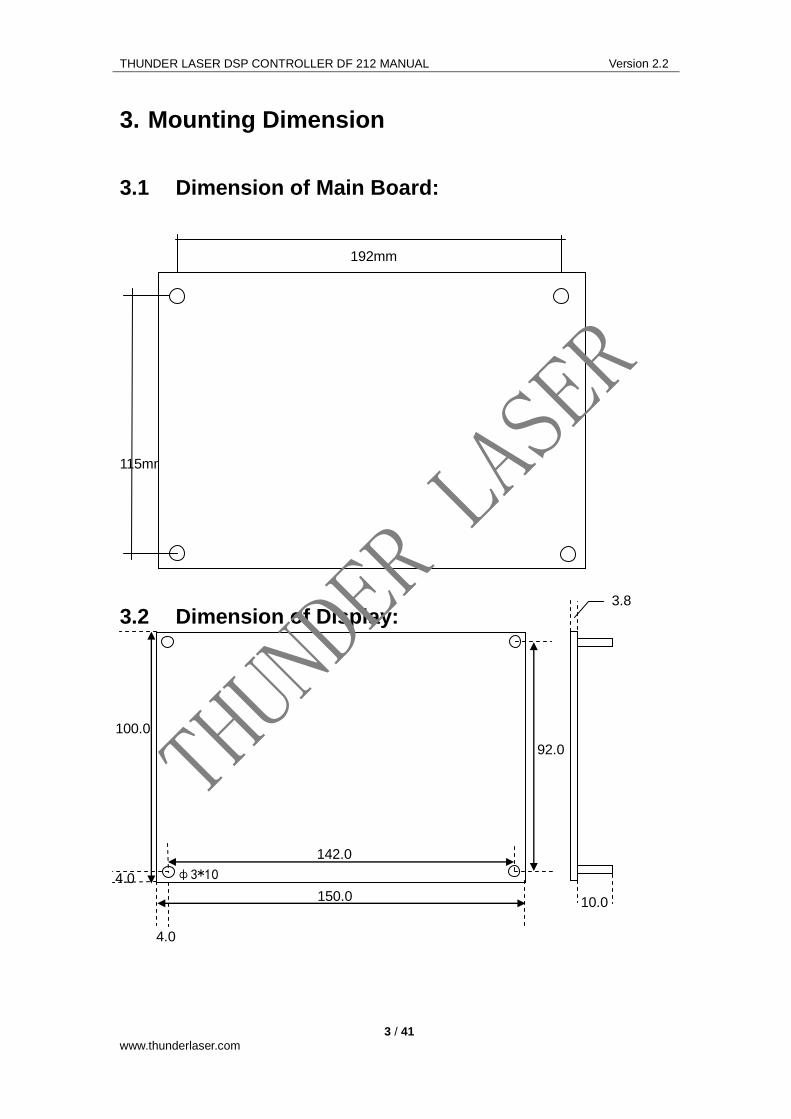
3. Mounting Dimension
3.1 Dimension of Main Board:
192mm
115mm
3.2 Dimension of Display:
100.0
150.0
ф3*10
142.0
4.0
4.0
92.0
10.0
3.8
THUNDER LASER

THUNDER LASER DSP CONTROLLER DF 212 MANUAL Version 2.2
4 / 41
www.thunderlaser.com
4. Interface of Main Board
Power 24V
DC (input)
U disk
24VDC
电源 Laser 2
Laser 1
IO
U
axis
Z
axis
Y
axis
X
axis
X/Y limit
Z/U limit
USB/PC
DS
P
LA
SE
R
CO
NT
RO
LLE
R
DF
211
display
THUNDER LASER

THUNDER LASER DSP CONTROLLER DF 212 MANUAL Version 2.2
5 / 41
www.thunderlaser.com
Pin Definition
1 2 3 4 5 6
Power 24V- 24V+
Laser 1 GND TTL+ TTL-
PWM
Water
protection
Laser 2 GND TTL+ TTL-
PWM
Footswitch 5V+
X-axis GND DIR+ DIR- PUL- PUL+ 5V+
Y-axis GND DIR+ DIR- PUL- PUL+ 5V+
Z-axis GND DIR+ DIR- PUL- PUL+ 5V+
U-axis GND DIR+ DIR- PUL- PUL+ 5V+
X/Y limit GND
Limit Y-,
Zero point
of Y Axis
Limit Y+,
Max point of
Y Axis
Limit X-,
Zero point
of X Axis
Limit X+,
Max point of
X Axis
5V+
U/Z limit GND
Limit Z-,
Zero point
of Z Axis
Limit Z+, for
the auto
focus
function
5V+
IO GND open
flap(input)
blow
air(output)
5V+
THUNDER LASER

THUNDER LASER DSP CONTROLLER DF 212 MANUAL Version 2.2
6 / 41
www.thunderlaser.com
5. How to Connect the 24V DC to the Controller
THUNDER LASER

THUNDER LASER DSP CONTROLLER DF 212 MANUAL Version 2.2
7 / 41
www.thunderlaser.com
6. How to Connect the Display
Pay attention to the direction and the connect the display
THUNDER LASER

THUNDER LASER DSP CONTROLLER DF 212 MANUAL Version 2.2
8 / 41
www.thunderlaser.com
THUNDER LASER

THUNDER LASER DSP CONTROLLER DF 212 MANUAL Version 2.2
9 / 41
www.thunderlaser.com
7. How to Connect the Laser Power Supply
Thunder laser DSP controller DF 212 can control two laser tubes. Laser 1 for tube 1,
Laser 2 for tube 2. And there're two kinds of wiring from controller to laser power supply:
TTL- and TTL +
7.1 TTL-
THUNDER LASER

THUNDER LASER DSP CONTROLLER DF 212 MANUAL Version 2.2
10 / 41
www.thunderlaser.com
7.2 TTL+
THUNDER LASER

THUNDER LASER DSP CONTROLLER DF 212 MANUAL Version 2.2
11 / 41
www.thunderlaser.com
8. How to Connect Motor Drivers
There are several kind of stepper drivers in the market. Different type of drivers have
different wirings. If the wirings are incorrect,the motors can not work properly. The most
important is that the "pulse" wiring must be correct. For the "direction", you can change in
the laser software if the direction is incorrect.below are different kind of wirings:
8.1 Pulse Signal Rising Edge (for 3 Pin Driver)
8.2 Pulse Signal Rising Edge (for 4 Pin Driver)
PLS+
PLS-
DIR+
DIR- 1
2
3
4
5
6
X/Y/Z/U
GND
DIR+
DIR-
PUL-
PUL+
5V
1
2
3
4
5
6
X/Y/Z/U
GND
DIR+
DIR-
PUL-
PUL+
5V +5V
PLS
DIR
THUNDER LASER

THUNDER LASER DSP CONTROLLER DF 212 MANUAL Version 2.2
12 / 41
www.thunderlaser.com
8.3 Pulse Signal Falling Edge (for 3 Pin Driver)
8.4 Pulse Signal Falling Edge (for 4 Pin Driver)
If the direction of the motor is reversed, user only need to change the wiring of "DIR" or
change the setting in the software
1
2
3
4
5
6
X/Y/Z/U
GND
DIR+
DIR-
PUL-
PUL+
5V +5V
PLS
DIR
PLS+
PLS-
DIR+
DIR- 1
2
3
4
5
6
X/Y/Z/U
GND
DIR+
DIR-
PUL-
PUL+
5V+
THUNDER LASER

THUNDER LASER DSP CONTROLLER DF 212 MANUAL Version 2.2
13 / 41
www.thunderlaser.com
9. How to Connect the Limit Switches for X/Y
Axis
9.1 Mechanical Switch
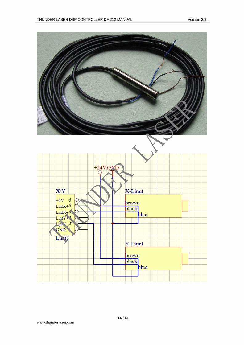
9.2 Proximity Sensor
Our controller support "NPN-NO" type proximity sensor. Please pay attention to the type
of the sensor when purchasing. There're there wires from the proximity sensor:
Black(signal), brown(power input), blue(GND). Since the controller can only support up to
DC 5V. And most proximity sensor need DC 10V-30V. The proximity sensor need to
connect to the extra switching power supply.
THUNDER LASER
THUNDER LASER DSP CONTROLLER DF 212 MANUAL Version 2.2
14 / 41
www.thunderlaser.com
THUNDER LASER

THUNDER LASER DSP CONTROLLER DF 212 MANUAL Version 2.2
15 / 41
www.thunderlaser.com
10. How to Connect the Limit Switches for Z
Axis
Z axis is used to control the motorized table and for the auto focus function.
Since the U axis is used for auto feeding systems, the limit switches are useless.
10.1 Mechanical Switch
If you don't need to use the auto focus function, you only need to connect the Pin "NO" on
limit switch to Pin4(LmtZ-) on the controller and also connect "COM" to "GND"
If you need to use the auto focus function, you will need to connect the Pin "NO" on the
Auto focus switch to Pin5(LmtZ+) on the controller and also connect "COM" to "GND"
See the below picture to learn the detail:
THUNDER LASER

THUNDER LASER DSP CONTROLLER DF 212 MANUAL Version 2.2
16 / 41
www.thunderlaser.com
10.2 Proximity Sensor
The wiring of the proximity sensor is nearly the same as the X/Y axis.There're three wires
from the proximity sensor: Black(signal), brown(power input), blue(GND). Since the
controller can only output DC 5V. And most proximity sensor need DC 10V-30V. The
proximity sensor need to connect to the extra switching power supply.
THUNDER LASER

THUNDER LASER DSP CONTROLLER DF 212 MANUAL Version 2.2
17 / 41
www.thunderlaser.com
11. No Water Proection、Pedal Switch、Open
Flap Protection、Blow Air Control
11.1 No Water Protection
The no water protection is used to turn off the laser when the water chiller is not working
properly. This will keep the laser safe.
Most power supply has already has the no water protection function. However, since our
controller has a display, when there's no water, the display will show the message. This is
more convenient for the user to judge the problem.
When using the no water protection fucntion,user need to use a short wire to connect Pin
WP and Pin GND on the power supply. See below to learn the detail:
THUNDER LASER

THUNDER LASER DSP CONTROLLER DF 212 MANUAL Version 2.2
18 / 41
www.thunderlaser.com
Since our controller only support no water protection for one laser tube, if your system has
two laser tubes, it's better to use the no water protection function on the laser power
supply. Below is the No water protection wirings for the power supply.
THUNDER LASER

THUNDER LASER DSP CONTROLLER DF 212 MANUAL Version 2.2
19 / 41
www.thunderlaser.com
11.2 Pedal Switch
Pedal switch has the same function as the "start/pause" button on the display. It is very
useful for some special jobs.
Below is the wiring for the pedal
switch
THUNDER LASER

THUNDER LASER DSP CONTROLLER DF 212 MANUAL Version 2.2
20 / 41
www.thunderlaser.com
11.3 Open Flap Protection
The open flap protection is used for safety purpose. When the user open the flap(cover),
the laser will stop working. User need to tick the Opening Protect in the laser software
when need this function.
Installing example:
THUNDER LASER

THUNDER LASER DSP CONTROLLER DF 212 MANUAL Version 2.2
21 / 41
www.thunderlaser.com
Below is the wiring:
For mechanical switch:
THUNDER LASER

THUNDER LASER DSP CONTROLLER DF 212 MANUAL Version 2.2
22 / 41
www.thunderlaser.com
For proximity sensor
THUNDER LASER

THUNDER LASER DSP CONTROLLER DF 212 MANUAL Version 2.2
23 / 41
www.thunderlaser.com
11.4 Blow Air Control
This function is used to control the air pump/exhaust fan. For this function, you will need
an extra board like below: (user can contact us to purchase this )
Below is the wiring:
THUNDER LASER

THUNDER LASER DSP CONTROLLER DF 212 MANUAL Version 2.2
24 / 41
www.thunderlaser.com
12. How to Use the Display
12.1 Function of the buttons
Arrow buttons: control the movement of the laser
head.(also can be used to change the parameters in the control panel)
Laser button: single press to draw a dot, press and hold to drill a hole.
Origin button: set the starting point for the laser head.
Box button: trace the path of the current job. Help user to put the material
on the correction position before starting the job.
Start/Pause button: run/pause the current job.
File :000
Power 1 :14.0/6.0%
Speed :150 mm/s
Wait . . . 000
THUNDER LASER
THUNDER LASER DSP CONTROLLER DF 212 MANUAL Version 2.2
25 / 41
www.thunderlaser.com
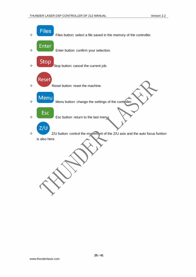
Files button: select a file saved in the memory of the controller.
Enter button: confirm your selection.
Stop button: cancel the current job.
Reset button: reset the machine.
Menu button: change the settings of the controller.
Esc button: return to the last menu.
Z/U button: control the movement of the Z/U axis and the auto focus funtion
is also here.
THUNDER LASER
THUNDER LASER DSP CONTROLLER DF 212 MANUAL Version 2.2
26 / 41
www.thunderlaser.com
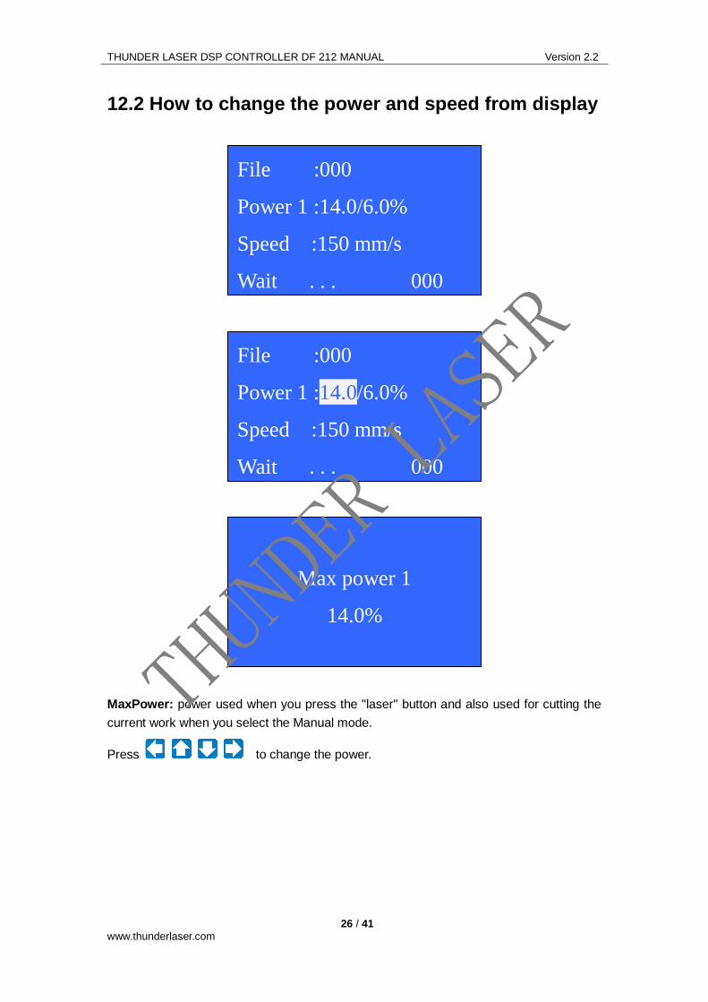
12.2 How to change the power and speed from display
MaxPower: power used when you press the "laser" button and also used for cutting the
current work when you select the Manual mode.
Press to change the power.
Max power 1
14.0%
File :000
Power 1 :14.0/6.0%
Speed :150 mm/s
Wait . . . 000
File :000
Power 1 :14.0/6.0%
Speed :150 mm/s
Wait . . . 000
THUNDER LASER

THUNDER LASER DSP CONTROLLER DF 212 MANUAL Version 2.2
27 / 41
www.thunderlaser.com
MinPower: power used for cutting the corners of current work when you select the
Manual mode.
Speed: moving speed of the laser head when you press the "arrows" and also speed for
the current job when you select the Manual mode.
Press to change the speed.
Speed
300 mm/s
File :000
Power 1 :14.0/6.0%
Speed :300 mm/s
Wait . . . 000
Min power 1
6.0%
File :000
Power 1 :14.0/6.0%
Speed :150 mm/s
Wait . . . 000
THUNDER LASER

THUNDER LASER DSP CONTROLLER DF 212 MANUAL Version 2.2
28 / 41
www.thunderlaser.com
Power1/Power2: if you machine has two laser heads, you can change this to control
power of different laser head.
File :000
Power 2 :14.0/6.0%
Speed :150 mm/s
Wait . . . 000
File :000
Power 1 :14.0/6.0%
Speed :150 mm/s
Wait . . . 000
THUNDER LASER

THUNDER LASER DSP CONTROLLER DF 212 MANUAL Version 2.2
29 / 41
www.thunderlaser.com
12.3 How to set different functions from display
Press button to show the following list:
Press to choose different menu. And then press to confirm.
1. Usb File Menu:Read files from Memory stick directly.
Please insert the memory stick to the USB port in the laser machine and then choose
UsbFile menu.
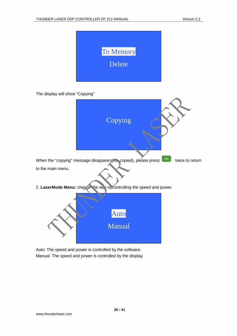
Choose the file you want to copy and then choose "To Memory" and confirm
001: File 1
002: File 2
003: File 3
004: File 4
5. MoveDistance
6. Frame
7. Format
8. Language
1. UsbFile
2. LaserMode
3. CutMode
4. FrameMode
THUNDER LASER
THUNDER LASER DSP CONTROLLER DF 212 MANUAL Version 2.2
30 / 41
www.thunderlaser.com
The display will show "Copying"
When the "copying" message disappears(file copied), please press twice to return
to the main menu.
2. LaserMode Menu: change the way of controlling the speed and power.
Auto: The speed and power is controlled by the software.
Manual: The speed and power is controlled by the display.
Auto
Manual
Copying
To Memory
Delete
THUNDER LASER

THUNDER LASER DSP CONTROLLER DF 212 MANUAL Version 2.2
31 / 41
www.thunderlaser.com
3. CutMode Menu: change the way of set the origin point(start working point).
PanelLocation: the starting point is decided by the on the display panel.
SoftLocation: the starting point is decided by the software.(the position of the drawing in
the Coordinates of the software)
4. FrameMode Menu: change the function of the button.
TrackFrame: track the frame of current work.
CutFrame: cut the frame of current work.
DotCorner: draw dots in the four corners of current work.
5. MoveDistance Menu: moving distance of the laser head when press the "arrows".
When the setting is "000.0mm", the laser head moves without break by pressing the
"arrow".
Distance
000.0mm
TrackFrame
CutFrame
DotCorner
PanelLocation
SoftLocation
THUNDER LASER
THUNDER LASER DSP CONTROLLER DF 212 MANUAL Version 2.2
32 / 41
www.thunderlaser.com
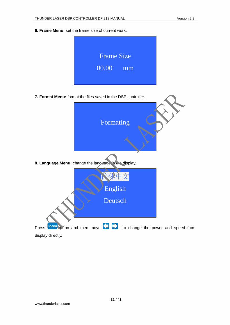
6. Frame Menu: set the frame size of current work.
7. Format Menu: format the files saved in the DSP controller.
8. Language Menu: change the language in the display.
Press button and then move to change the power and speed from
display directly.
简体中文
English
Deutsch
Formating
Frame Size
00.00 mm
THUNDER LASER

THUNDER LASER DSP CONTROLLER DF 212 MANUAL Version 2.2
33 / 41
www.thunderlaser.com
12.4 How to use U/Z and auto focus.
Press button to show the following list:
Press to move to different menu.
And press to control the movement of U/Z axes
ZAxesMove
UAxesMove
ZAxesReset
AutoFocus
ZAxesMove
UAxesMove
ZAxesReset
AutoFocus
THUNDER LASER

THUNDER LASER DSP CONTROLLER DF 212 MANUAL Version 2.2
34 / 41
www.thunderlaser.com
Choose "ZAxesReset" and press confirm to reset the Z axes(motorized table will move
down till it reach the limit switch on the bottom)
Choose "AutoFocus" and press confirm to use the auto focus function. (the table will keep
moving up till it reach/get near to the limit switch in the laser head and then move back to
the correct focus)
ZAxesMove
UAxesMove
ZAxesReset
AutoFocus
Z Reseting
ZAxesMove
UAxesMove
ZAxesReset
AutoFocus
THUNDER LASER

THUNDER LASER DSP CONTROLLER DF 212 MANUAL Version 2.2
35 / 41
www.thunderlaser.com
13. Ending
Above the general manual for installing Thunder Laser DSP Controller DF 212. If users
have more questions.please contact us freely and send email to "[email protected]"
We will try our best to help you.
Thanks again for purchasing our products.
THUNDER LASER TEAM
2012
THUNDER LASER

THUNDER LASER DSP CONTROLLER DF 212 MANUAL Version 2.2
36 / 41
www.thunderlaser.com
Add Additional: Thunder Laser Products
(1) DSP Laser Controller-------DF212
Thunder Laser Controller will make your work easy and relax.
For more information on DSP Laser Controller DF212, please visit our website:
http://www.lasercontrolsystems.com.
THUNDER LASER
THUNDER LASER DSP CONTROLLER DF 212 MANUAL Version 2.2
37 / 41
www.thunderlaser.com
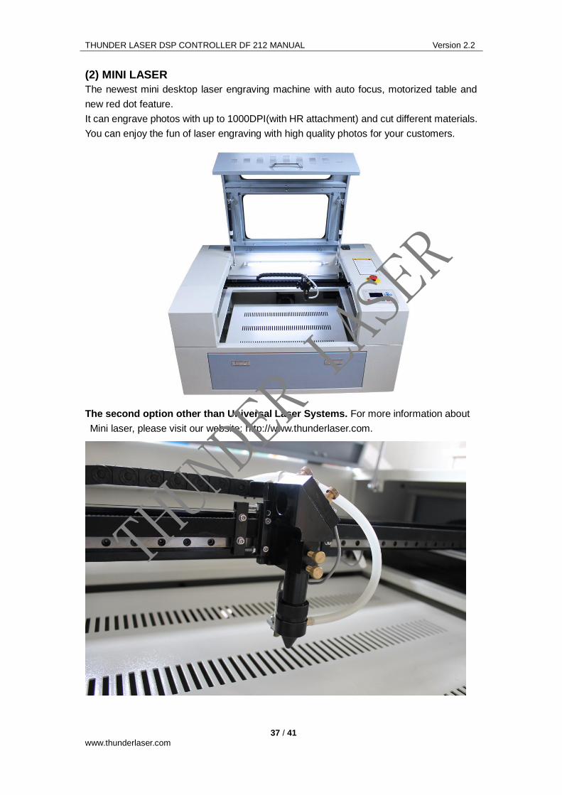
(2) MINI LASER
The newest mini desktop laser engraving machine with auto focus, motorized table and
new red dot feature.
It can engrave photos with up to 1000DPI(with HR attachment) and cut different materials.
You can enjoy the fun of laser engraving with high quality photos for your customers.
The second option other than Universal Laser Systems. For more information about
Mini laser, please visit our website: http://www.thunderlaser.com.
THUNDER LASER

THUNDER LASER DSP CONTROLLER DF 212 MANUAL Version 2.2
38 / 41
www.thunderlaser.com
(3) MARS LASER
with the supper large work area, Mars laser cutter can be used to cut almost all materials
at an excellent quality. And can also be used to engrave on big materials like doors,
glasses etc.
The second option other than Universal Laser Systems. For more information Mars
laser, please visit our website: http://www.thunderlaser.com.
THUNDER LASER

THUNDER LASER DSP CONTROLLER DF 212 MANUAL Version 2.2
39 / 41
www.thunderlaser.com