THROUGH SCIENCE DEFEND TECHNICAL REPORT AD … · Figure 5-CBT -Q Components ..... 6 Figure 6-User...
62
THROUGH SCIENCE TECHNICAL REPORT NATICK/TR-00/020 VIE DEFEND A AD ______ _ COMBAT CUEING: GEOLOCATION SYSTEM FOR LOW PROBABILITY OF INTERCEPT SIGNALS by Doug Vujcic and Kerry Kachejian Raytheon Falls Church, VA 22042 October 2000 Final Report June 1996 - November 1999 Approved for Public Release; Distribution is Unlimited Prepared for U.S. Army Soldier and Biological Chemical Command Soldier Systems Center Natick, Massachusetts 01760-5015
Transcript of THROUGH SCIENCE DEFEND TECHNICAL REPORT AD … · Figure 5-CBT -Q Components ..... 6 Figure 6-User...

THROUGH SCIENCE
TECHNICAL REPORT NATICK/TR-00/020
VIE DEFEND
A ~<l3 LJs~ AD ______ _
COMBAT CUEING: GEOLOCATION SYSTEM FOR LOW PROBABILITY OF INTERCEPT SIGNALS
by
Doug Vujcic and
Kerry Kachejian
Raytheon Falls Church, VA 22042
October 2000
Final Report June 1996 - November 1999
Approved for Public Release; Distribution is Unlimited
Prepared for U.S. Army Soldier and Biological Chemical Command
Soldier Systems Center Natick, Massachusetts 01760-5015

DISCLAIMERS
The fmdings contained in this report are not to
be construed as an official Department of the Army
position unless so designated by other authorized
documents.
Citation of trade names in this report does not
constitute an official endorsement or approval of
the use of such items.
DESTRUCTION NOTICE
For Classified Documents:
Follow the procedures in DoD 5200.22-M:~ Industrial
Security Manual, Section Il-19 or DoD 5200.1-R,
Information Security Program Regulation, Chapter IX.
For Unclassified/Limited Distribution Documents:
Destroy by any method that prevents disclosure of
contents or reconstruction of the document.

REPORT DOCUMENTATION PAGE Form Approved OMB No. 0704-0188
The public reporting burden for this collection of information is estimated to average 1 hour per response, including the time for reviewing instructions, searching existing data sources, gathering and maintaining the data needed, and completing and reviewing the collection of information . Send comments regarding t his burden estimate or any other aspect of this collection of information, including suggestions for reducing the burden, to Department of Defense, Washington Headquarters Services, Directorate for Information Operations and Reports (0704-0188). 1215 Jefferson Davis Highway, Suite 1204, Arlington, VA 22202-4302. Respondents should be aware that notwithstanding any other provision of law, no person shall be subject to any penalty for fai ling to comply with a collection of information if it does not display a currently valid OMB control number. PLEASE DO NOT RETURN YOUR FORM TO THE ABOVE ADDRESS.
1. REPORT DATE (DD-MM- YYYYJ ,2. REPORT TYPE 3 . DATES COVERED (From- To) 05-10-2000 Final Report June 1996- November 1999
4 . TITLE AND SUBTITLE Sa. CONTRACT NUMBER COMBAT CUEING: GEOLOCATION SYSTEM FOR LOW C-DAAK60-9&-C-3024 PROBABILITY OF INTERCEPT SIGNALS
Sb. GRANT NUMBER
Sc. PROGRAM ELEMENT NUMBER
6. AUTHOR(S) Sd . PROJECT NUMBER D. Vujcic and K. Kachejian
Se. TASK NUMBER
Sf. WORK UNIT NUMBER
7 . PERFORMING ORGANIZATION NAME(S) AND ADDRESS(ES) 8 . PERFORMING ORGANIZATION Raytheon Company REPORT NUMBER 7700 Arlington Boulevard Falls Church, Virginia 22042-2900
9. SPONSORING/MONITORING AGENCY NAME(S) AND ADDRESS(ES) 10. SPONSOR/MONITOR'S ACRONYM(S) Sponsor: Defense Advanced Research Projects Agency (DARPA) Microsystems Technology Office (E. C. Urban) 3701 North Fairfax Drive Arlington, VA 22203-1714 11 . SPONSOR/MONITOR'S REPORT
NUMBER(S) NATICK/TR-00/020
12. DISTRIBUTION/AVAILABILITY STATEMENT Approved for Public Release; Distribution Unlimited
13. SUPPLEMENTARY NOTES Monitor: US Army Soldier and Biological Chemical Command, Soldier Systems Center, ATTN: AMSSB-RSS-D(N) (H. Girolamo), Natick, MA 01760-5020
14.ABSTRACT Raytheon Company has successfully developed and demonstrated a revolutionary new signals exploitation system that weighs 10 times less than conventional technology. Developed under DARPA's Smart Module program, Combat Cueing is a human-portable system that provides radio frequency (RF) situational awareness to small military units , allowing the warfighter to detect and locat f-in real time low-probability-of-intercept (LPI) transmitters operating between 30 and 88 MHz. Raytheon conducted field demonstrations of Combat Cueing at Ft. A.P Hill , VA. System modules, mounted on HMMWV military vehicles , successfully detected and located threat radios with 250 meter accuracy. The system employed a novel baud-phase time-difference-of-arrival (TDOA) algorithm, which calculated emitter locations by measuring demodulated signal symbol (baud) arrival times at each of the modules. By simultaneously reducing the space, weight, power and cost of conventional systems , these all-weather modules are operational across a broad spectrum of platforms, including tactical ground vehicles, robots, unmanned aerial vehicles, helicopters and ships , or may be left unattended on buildings, towers or the battlefield.
15. SUBJECT TERMS CUEING RF (RADIO FREQUENCY) GEOLOCATION TDOA (TIME DIFFERENCE OF ARRIVAL RADIO EMITTER LOCATION PORTABLE LPI (LOW PROBABILITY OF INTERCEPT) WEIGHT REDUCTION SITUATIONAL AWARENESS SIGNALS EXPLOITATION PROJECT
16. SECURITY CLASSIFICATION OF: 17. LIMITATION OF 18. NUMBER 19a. NAME OF RESPONSIBLE PERSON
a. REPORT b. ABSTRACT c. THIS PAGE
UNCLASSIF UNCLASSIF UNCLASSIF lED JED lED
ABSTRACT OF PAGES
SAR 60
Henry Girolamo , Program Manager
19b. TELEPHONE NUMBER flnclude area codeJ
508-233-5071
Standard Form 298 (Rev. 8/98) Prescribed by ANSI Std . Z39.18


TABLE OF CONTENTS Page No.
List of Figures .....•..•.•........•....•..•....••..•...................................•...........................•............•.•...•...•..•....••....•.........• v
List of Tables .........•.•.•••....•..•••.••••...•......•.•..•.••........•...••••••..•..••.......••.••......•.••.••••..••..•.••..•.•.....•...•..••.•...•..••.•.••. vii
Preface and Acknowledgements •••.•.•••.••.•.•...•....••.•....•.•.•.•••..•••......••..••....•.•••.•••••.•..•..•••.•..•...•.•..••.•........••••...• viii
1. Summary ..•....•..••....•.•......••••••.•..•.••••••.•...••.....••••..•••.•.•••.•••..••..••...........•.•.•••••.....••••••.••.••.••.••••••..•.•.•...•...........••.•• 1
2. Introduction ....•..••.•......•..•.••.•.•.••..••.••.•....•...•.•.•...•••.............•...•...••.•.•.......•...••.•..•..••..••••..•.•...••••..•.•.......•..........•• 2
3. Methods, Assumptions, and Procedures •...•••••.........••.•••...•..••....••.....•..••••..•..••••..••.••.•••.•.•...•.••..•...............•..•.•• 3
3.1. Task 1 -Requirements Analysis and Conceptual Design. ......... ......................... ... ....... ............................ ...... 3 3.1.1. Military Mission Relevance of Combat Cueing .................................................................................... 3
3.1.1.1. The Problem: Real-time Information for Small Unit Operations ..................................................... 3 3.1.1.2. The Solution: Combat Cueing ............ ............. ................................................................................. 3 3 .1 .1.3. Military Advantages ......................................................................................................................... 4
3.1.2. ConceptofOperation ............................................................................................................................ 5 3 .1.3. System Partitioning ................................................................................................................................ 6 3.1.4. User Interface and. Human Factors Analysis ......................................................................................... 7 3.1.5. System Requirements ............................................................................................................................ 7
3.2. Task 2 -Algorithm Research and Development ..................... .............................. .. ........ .. .......... .. .. ....... ...... . 10 3 .2.1. Processing Algorithms ... . ........ ..... ... ......... ...... ... . . . . . ... . . .... .. .. .. .. .... .... ..... .. . ..... ... .. . .... .. .. . ....... .. .. ............. 10 3.2.2. 20 Questions ........................................................................................................................................ 13 3.2.3. Simulation ........................................................................................................................................... 14
3.3. Task 3 -Hardware Development .................................. .. ...................................................... ..... .................. 15 3.3.1. Requirements Analysis ........................................................................................................................ 15 3.3.2. Design ................................................................................................................................................. 17
3.3.2.1. Chassis ............................................................................................................................................ 18 3.3.2.2. Small PCI Cards ............................................................................................................................. 19 3.3.2.3. Thermal Characteristics .................................................................................................................. 21
3.3.3. Build, Integration and Test. ................................................................................................................. 21 3.3.3.1. RF-IF CCA ..................................................................................................................................... 21 3.3.3.2. PE CCA .................................................................... ...................................................................... 22 3.3.3.3. Embedded Controller ..................................................................................................................... 22 3.3.3.4. TAG CCA ...................................................................................................................................... 22 3.3.3.5. VEST .............................................................................................................................................. 23 3.3.3.6. Radios ............................................................................................................................................. 24 3.3.3.7. PLGR GBS Receiver .................................................................................................................. : ... 24
111
CONTENTS (Coot' d)
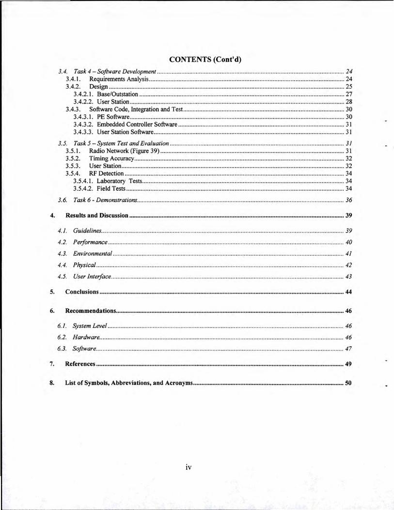
3.4. Task 4- Software Development ................... .... ........... ... .. .............. .......... ............. ..... ... ............... ... ............. 24 3.4.1. Requirements Analysis ........................................................................................................................ 24 3.4.2. Design ................................................................................................ ........... .... .......... .. ...................... 25
3.4.2.1. Base/Outstation .............................................................................................................................. 27 3.4.2.2. User Station ........................................ ............................................................................................ 28
3.4.3. Software Code, Integration and Test ................................................................................................... 30 3.4.3.1. PE Software .................................................................................................................................... 30 3.4.3.2. Embedded Controller Software .......................... ...... ...................................................................... 31 3.4.3.3. User Station Software .................. ................................................................................................... 31
3.5. Task 5- System Test and Evaluation ...... .... ... .. ... ........ .. ........................... .............................. .... ...... .... ...... .. 31 3.5.1. Radio Network (Figure 39) ................................................................................................................. 31 3.5.2. Timing Accuracy ............... .......................................................................... ........................................ 32 3.5.3. User Station ....................................................................................................... .................................. 32 3.5.4. RF Detection ............................................................... ................ ........................................................ 34
3.5.4.1. Laboratory Tests ............................................. ............................................................................... 34 3.5.4.2. Field Tests ...................................................................................................................................... 34
3.6. Task 6- Demonstrations ..... .. ... .. ..... ... ...... ........... .. ........ ..... ......................... ................ ... .... .... ... .... ............... . 36
4. Results and Discussion .........................................•.......................•..................................•....•........•................. 39
4.1. Guidelines ......... .... .. .. ....... .. ....... .... ...... .... ... .. ...... .. .... ........ ... .. ............... .... .. .. ..... ..... ......... ..... ......................... 39
4.2. Performance ..... ........ ... ...... ... ... ...... ........ .. .... ........ ....... .. ... ...................... ......... .... ....... ....... ... ......................... 40
4.3. Environmental ..... ................. ............................. ..... ............ ....... ..... .... ..... .... ........... .. ...... ..... ......................... 41
4.4. Plrysical ....... ........... ................................... .. .............. ... .... ........................ ... .......... ............... ........ ....... ... .... .. 42
4.5. User Interface ... .................... ..... .................... .... .............. ...... ... .... .... ....... .. ...................... ......... ........ ..... ..... .. 43
5. Conclusions .••.•......•....................•............................•.....................•................................................•.........•....... 44
6. Recommendations ..............................................................................................................•...............•....•........ 46
6.1. System Level ...... ............. ...... .... .... ..................... .. .. ................ ... .... .. .......... ........ ........ .... ......... ....... ........ ........ 46
6.2. Hardware ..................................... .... ... ........ .......... ........... .... .. .................... ..... ... ............ .... ....... ... .... ... ... .. ..... 46
6.3. Software ...... ....... .. ............. .. .... ...................... .. .. .. ......... .... ... ........ .............................. ... .................. ............. .. 47
7. References .•........•.............•.•...................................••.•........................................................................•............. 49
8. List of Symbols, Abbreviations, and Acronyms ............................................................................................ 50
IV

LIST OF FIGURES
Figure 1 -Combat Cueing system enhances battlefield awareness ..............••....•...•••..•....•...•.••........••....•..•..••.....•.•. 1 Figure 2- Combat Cueing Module ............................................................................................................................ 3 Figure 3 - CBT -Q Extends Situational Awareness ••.............•................•...•.....•.•.......•.••..•..•...........••.....•.•..•..••..•..•... 5 Figure 4- Geolocation algorithm is based on time difference of arrival of target emitter signal ....................... 5 Figure 5- CBT -Q Components ................................................................................................................................. 6 Figure 6- User Station Functions ............................................................................................................................. 6 Figure 7- Basestation and Outstation Functions ••••...•....•.......•••.....••....••.••....•.•.•.....•.••.•.....••....•...••.....•.•.•••.••..•..•.•• 6 Figure 8 - System Operational Concept •••.••....••..•••••...•••...•...••...••......•...•.•.•....••••....•.•••••.••..•.••....••..••.••..•.•.••..•...•..•.•. 8 Figure 9 - CBT -Q System High Level Data Flow •••••...........••....•••.....•.....•.•.....•........••.••.•..•...•....•••........•.•..••........•.•. 9 Figure 10- Jaguar's frequency hopping across 30-88 MHz alludes conventional narrowband search, detect,
and track algorithms, which makes it a low-probability of intercept radio ..•.•..••..•.••........••.•...••••.•..••....... 11 Figure 11 - CBT -Q Algorithm relies on rapid data acquisition across the entire 30-88 MHz band. A sliding 10
MHz scan window covers the entire band in 1.5 seconds. This method has a high probability of detection for most hopping sequences .•.••.•••.••..•••••..••.•.•...••....•••.•••.•.•....•....•.•...•.•..••..•..•...........•...•..••••.•..••.••. 11
Figure 12- Baud phase minimizes data transfer times between sensors, decreases own detectability, and dramatically improves geolocation response time to the warfighter .......................................................... 12
Figure 13- Threat signal sorting minimizes the probability of false alarms ..•.......•.••..•..•..•.....•.....••..•.•...•.•.....••. 13 Figure 14- Small PCI standard met most of the evaluation criteria ...••.•...•...•.••..•.•.•....••...•...........••...•..•.••.•..•.••. 14 Figure 15- Surrounding target emitter with CBT -Q sensors leads to improved geolocation accuracy .•.••...•••. 15 Figure 16- Initial concept for Combat Cueing Sensor packaging was based on a 4"x4"x6" chassis ...•..•.....••. 15 Figure 17- RF detection and geolocation process'ing requirements ....••.•••••.•...•.....•..•..••••.••.•..••..••.•••••.•..•••••..•.••. 16 Figure 18 - Basestation/Outstation modules and Constituent Subsystem Electrical/Data Interfaces •...••••....••. 16 Figure 19- User Station Block Diagram ...••..•.•...••••.•..••.•...............•..•••••.••.•.•••.•.......•.•.•...•.•...•........•..••..•.•..•..••....••. 17 Figure 21 - CBT -Q Module Chassis Features ••..••••.••..••...•..•••.........••......•.•...•.......•.••..••........•......•....••..•...•.•.••.....•. 18 Figure 20- CBT -Q Module Interconnect Diagram •...•....••.•••.••••..•.•••...•.•.•.•...•...•.....•.....•.•...•.....•..•......•.....•.••..•..•. 18 Figure 22 - CBT -Q Module Chassis ..........•.....•...••.•.....••..............•....••..........••.......•.•.•..•..•.•...•............•......••..••.....•. 19 Figure 23- CBT-Q Chassis' HMMWV Power Adapter (top) and Battery Pack (bottom) ............................... 19 Figure 24 Card construction includes two circuit cards, shields, and housing .•...•.•.•..•..•..........•.••.••..•...••..•......•. 19 Figure 25- RF-IF Circuit Card Assembly ••...••.•••••••...•...••...•...•.•......•.....•..•.•..•.•.........•.....•........•.•........•....•........... 20 Figure 26- This Pentium-based Embedded Controller card was never delivered by the vendor. An alternate
card from Ziatech was selected an interim solution ....•...••.....••..••••.•..•..•.•••..••.•.••..•.••..•.....••.••.••..•..•.••.•......•. 20 Figure 27 - TMS320C62 portion of the PE CCA ••...............•....•.....••.....•.......•...........••..•..•..•........•..••.......••.•.•....•. 20 Figure 28- Combat Cueing Hardware ................................................................................................................... 21 Figure 29 - Megatel Small PCI Embedded Controller was replaced by Ziatech Compact PCI Embedded
Controller. This change led to some chassis modifications ....•....•••.••.•...••.......•....•......•.....•...•.••....•..••.••..•..•. 22 Figure 30- User Station Vest and Associated Components .....••.....••.•••••.••....•.•....•..•.••..•..•..•........••.••.••.•..•..••....... 24 Figure 31 - CBT -Q Software High Level Data Flow •••.•...•.....••••.••..••.••.•..•....••.•.......•.••.••.....•......•..•.••....•...•.••..•.••. 25 Figure 32 - Basestation manages Outstations ........................................................................................................ 26 Figure 33- CBT -Q Parallel Processing Timing Sequence .•...••.•.•...............•..•..•......•.....•.•..•..••............•.....•.....•.••. 27 Figure 34- Software divided software into three Computer Software Configuration Items (CSCis) .•..••.....•. 27 Figure 35- Basestation and Outstation CSCis were built in three stages .•.••...•...•••..•.••.•..••..•........•...........••..•.••. 28 Figure 36 - User Station software functions ...••..•.••..............••.••••..•..•...........•.••....•..•.•...........•..•..•.•.•..•....•..•...•..•.•.. 28 Figure 37 -User Station Main Window ••.......••..••.•..............••..•••..•..••..........•.••.......•••.....•.....•........••.••.......••.•...•.•.. 29
v
FIGURES (Cont'd)
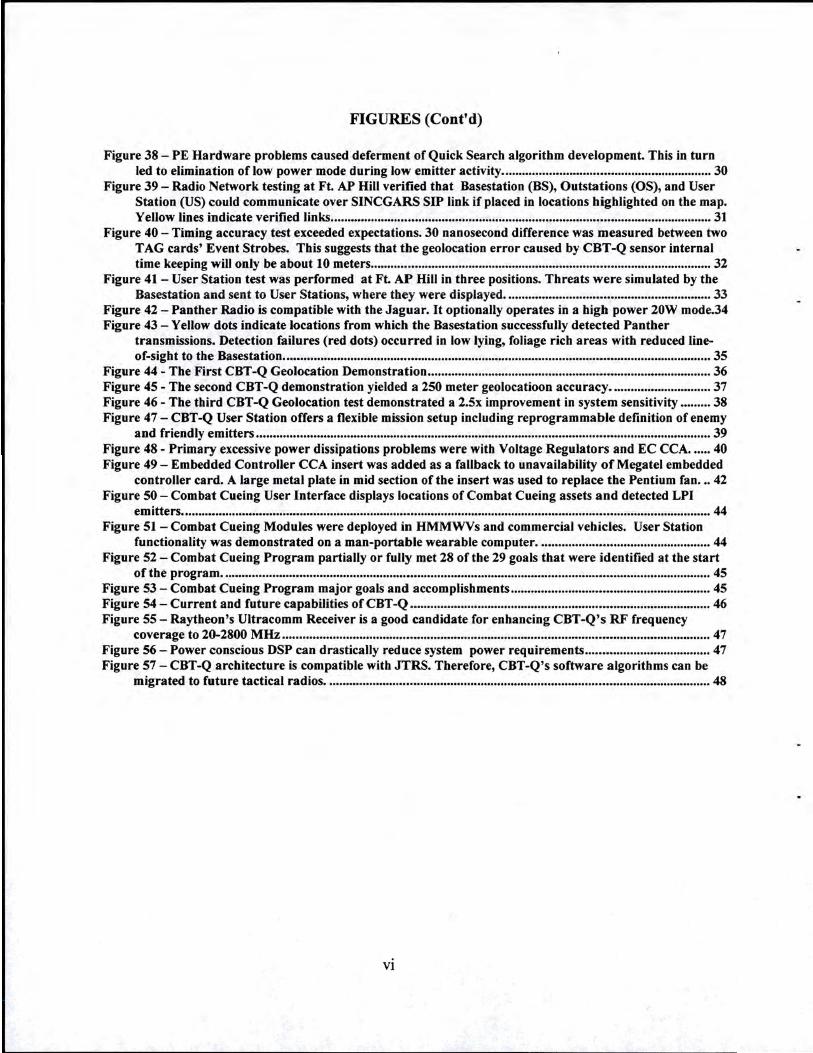
Figure 38 - PE Hardware problems caused deferment of Quick Search algorithm development. This in turn led to elimination of low power mode during low emitter activity ..........•.....•.•..••......•••........•...••.......••.•..... 30
Figure 39 - Radio Network testing at Ft. AP Hill verified that Basestation (BS), Outstations (OS), and User Station (US) could communicate over SINCGARS SIP link if placed in locations highlighted on the map. Yellow lines indicate verified links ................................................................................................................. 31
Figure 40 - Timing accuracy test exceeded expectations. 30 nanosecond difference was measured between two TAG cards' Event Strobes. This suggests that the geolocation error caused by CBT -Q sensor internal time keeping will only be about 10 meters ....••..••..••...••.......•....•..•.••.•.•.•...•.•••••••.•••••••..••••••..•.•.•....••................ 32
Figure 41- User Station test was performed at Ft. AP Hill in three positions. Threats were simulated by the Basestation and sent to User Stations, where they were displayed ............................................................. 33
Figure 42 - Panther Radio is compatible with the Jaguar. It optionally operates in a high power 20W mode.34 Figure 43 - Yellow dots indicate locations from which the Basestation successfully detected Panther
transmissions. Detection failures (red dots) occurred in low lying, foliage rich areas with reduced line-of-sight to the Basestation .••••....••••••..••.••.•....•••..•.•..••...••......•••••.•......•••..•..•••••.•..•...••.....••••••...••..•..••.••.............. 35
Figure 44 - The First CBT -Q Geolocation Demonstration ••.••••....•..••••.••••••.•..•••••.••••..•••.••.•••••••...••.••••••••.•.••••..•••••. 36 Figure 45 - The second CBT -Q demonstration yielded a 250 meter geolocatioon accuracy .............................. 37 Figure 46 - The third CBT -Q Geolocation test demonstrated a 2.5x improvement in system sensitivity ••.•..... 38 Figure 47- CBT-Q User Station offers a flexible mission setup including reprogrammable definition of enemy
and friendly emitters •.......•••••...•.••••..•.•.••••••..•.••...•••••...••....•.••..••.......•••..•..••...••.....•••..•...••••••...•....•..••....••••••...•. 39 Figure 48 - Primary excessive power dissipations problems were with Voltage Regulators and EC CCA •..... 40 Figure 49 - Embedded Controller CCA insert was added as a fallback to unavailability of Mega tel embedded
controller card. A large metal plate in mid section of the insert was used to replace the Pentium fan •.• 42 Figure 50 -Combat Cueing User Interface displays locations of Combat Cueing assets and detected LPI
emitters ....•...••.••.....••••.••.••.••.•••....•.•..........••.•..•••....•••••...••...••.••....••.•......•.•......••...•.••....•....•..•••......••.•••.•.••.•..•...•. 44 Figure 51 -Combat Cueing Modules were deployed in HMMWVs and commercial vehicles. User Station
functionality was demonstrated on a man-portable wearable computer ................................................... 44 Figure 52 -Combat Cueing Program partially or fully met 28 of the 29 goals that were identified at the start
of the program •...•.•..........•....••.••..•......•••......••.•.....••••.•.......•.•.....•..•...............•••••••••..•......•..•....•...•......•.....•.•...•. 45 Figure 53 -Combat Cueing Program major goals and accomplishments ........................................................... 45 Figure 54- Current and future capabilities of CBT -Q ••...••..•••.••.•..••.•.•...••.••.••.••••.••.•.•••••..•.•••••.•..•..•..•••.•..•.•.••.•.•. 46 Figure 55- Raytheon's Ultracomm Receiver is a good candidate for enhancing CBT-Q's RF frequency
coverage to 20-2800 MHz •••.•••••••...•.•.••••.....••......••••••..•.....•.••....•....•••.••.•..••••...•.•••..•.••...••••••.••.....•.••..•..•.•••.•.... 47 Figure 56- Power conscious DSP can drastically reduce system power requirements ....•.•••..•.....•.•••.....••.....••. 47 Figure 57- CBT -Q architecture is compatible with JTRS. Therefore, CBT -Q's software algorithms can be
migrated to future tactical radios .....•.••.••....•.•...•••••...••.•••..•.•...••...•.••......••.•..•..•...••.......•••••.••••..••.••..•..•.•..•.•... 48
vi

LIST OF TABLES
Table 1- Special Operations CBT-Q Management System Specification ........................................................... 23 Table 2-Ft. AP Hill RF Detection Test Summary ....•..............•.•......••......................••..•...........•.....•......•........•..... 35
Vll
PREFACE
Raytheon (formerly Raytheon E-Systems and Raytheon Systems Company) has developed Combat Cueing capability under contract DAAK60-96-C-3024, CLIN 0001 and CLIN 0002. The program duration was from May 1996 to November 1999. The program was funded by the Defense Advanced Research Projects Agency (DARPA) ETO (E. Urban).
ACKNOWLEDGEMENTS
Henry Girolamo of the U.S. Army Soldier Systems Center- Natick RDE Center managed the program and provided critical guidance. PM NV /RST A provided test facilities and personnel to support Combat Cueing field demonstrations and evaluation at Ft. AP Hill, VA. Boeing was a subcontractor on the Combat Cueing program, providing a wearable "User Station" and related software.
Vlll

COMBAT CUEING: GEOLOCATION SYSTEM FOR LOW PROBABILITY OF INTERCEPT SIGNALS
1. Summary The pri1nary objective of this research was to develop and demonstrate a revolutionary signals exploitation module (Figure 1) that weighs 10 times less than conventional technology, uses 1000 ti1nes less module-to-1nodule network bandwidth, and provides radio frequency (RF) situational awareness to small military units. Intended functionality allows the warfighter to detect and locate low-probability-of-intercept (LPI) trans1nitters operating between 30 and 88 MHz, with minimal latency.
Raytheon conducted silnulations, hardware design, signal processing algorithm develop1nent, de1nonstrations and tests. Field tests of Combat Cueing were held at Ft. A.P Hill, VA. System 1nodules, mounted on HMMWV military vehicles, successfully detected Panther Radios 8.5 km away. In similar experiments, Panther threat radios were located with an accuracy of 250 1neters. The syste1n etnployed a time-difference-of-arrival (TDOA) location algoritmn, which calculated emitter locations by measuring average signal symbol arrival times at each of the modules.
A fully-loaded Combat Cueing Inodule weighs only six pounds and tneasures 6"x6"x5" . By si1nultaneously reducing the space, weight, power and cost of conventional systetns, these all-weather modules are operational across a broad spectrutn of platforms, including tactical ground vehicles, robots, urunanned aerial vehicles, helicopters and ships, or may be left unattended on buildings, towers or the battlefield.
o ba C e· ( )
• A tactical cueing technology for warfighters
• instantly detects/geolocates tactical emitters j 1--t--+--+---t--t--t-t
h.:-:.:.•:,.iifi~ • Disseminates data to small unit warflghters; f-+~-+--.:-~----~--.!..__._,
'iii~ • Supports mounted & dismounted operations/
CBT-Q Smart Module
• Improves situational awareness / • Platform and Link Independent /
I • Utilizes passive sensor technology f • Interfaces to the Digital Battlefield /
I I
I I
I
t/ ------__,..,=---
Small Unit • Passive Operation • Receives Cueing Data
Figure 1 - Combat Cueing system enhances battlefield awareness
1

The Combat Cueing module achieves its miniature size by employing credit card size circuit cards that are compliant with the industry Small PCI and PCMCIA standards. The module houses 10 Small PCI slots and two PCMCIA slots, embedded GPS receiver engine, Pentium® based Embedded Controller, GPS and RF antennas, and power regulators and filters. The system functionality can be extended through insertion of Raytheon's other small PCI and PCMCIA circuit cards.
2. Introduction The purpose of this report is to describe the execution and findings of DARPA's Combat Cueing (CBT-Q) program. The report is divide in four sections, 3.0 - 7.0, as follows:
Section 3.0, titled Methods, Assumptions, and Procedures describes six main Combat Cueing tasks:
1. Requirements Analysis and Conceptual Design
2. Algorithm Research and Development
3. Hardware Development
4. Software Development
5. System Test and Evaluation
6. Demonstrations
Section 4.0, titled Results and Discussion, Cueing Program goals and achievements. Section 5.0, titled Conclusions, contains the summary and discussion of the program results. Section 6.0, Recommendations, describes ongoing related research and offers recommendations for future research.
2
3. Methods, Assumptions, and Procedures
3.1 . Task 1 - Requirements Analysis and Conceptual Design
The purpose of this task was to perform the analysis of the military mission relevance of Combat Cueing, determine CBT-Q concept of operation, system requirements, evaluate system partitioning, and perform human factors and user interface analysis.
3.1.1.
3.1.1.1.
Military Mission Relevance of Combat Cueing
The Problem: Real-time Information for Small Unit Operations
Small unit warfighters are blind in the RF spectrum. Their situational awareness is limited to their eyes, a pair of night vision goggles, and at best a hand held thermal imager with a narrow field of view. Current RF information systems run at the wrong time constant for warfighters involved in small unit operations. Today's RF information systems start by collecting data from various ground and airborne sensors. By the time it is filtered, processed, and disseminated to front line warfighters, the information's tactical usefulness has expired.
Small unit warfighters need combat information systems that provide real-time information on enemy forces . For example, a U.S. tank commander (TC) wants to know "where is an enemy tank, right now!", so he can have his gun barrel pointed in the right direction. If provided with such timely information, warfighters could engage the enemy faster and increase the probability of target destruction. Furthermore, if the information system could identify which tactical targets are highest priority (e.g., command vehicles), these targets could be engaged first. By getting the "first shot" at enemy vehicles and engaging key targets first, U.S . forces will have a strong tactical advantage over potential adversaries.
3.1.1.2. The Solution: Combat Cueing
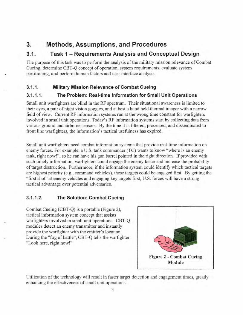
Combat Cueing (CBT -Q) is a portable (Figure 2), tactical information system concept that assists warfighters involved in small unit operations. CBT -Q modules detect an enemy transmitter and instantly provide the warfighter with the emitter's location. During the "fog of battle", CBT-Q tells the warfighter "Look here, right now!"
Figure 2 - Combat Cueing Module
Utilization of the technology will result in faster target detection and engagement times, greatly enhancing the effectiveness of small unit operations.
3

CBT -Q technology can support land, sea, and air warfighting operations. The modules are platform independent, which permit their use with wheeled and tracked vehicles, aircraft, ships, or left unattended.
3.1.1.3. Military Advantages
CBT -Q offers a new capability for small unit operations. Utilizing signal processing and advanced packaging, CBT -Q brings information warfare to the cutting edge of the battlefield. CBT-Q has several compelling military advantages for small units :
• Extends situational awareness into the RF spectrum
• Identifies and locates enemy C3I targets
• Open architecture design permits tactical flexibility
• Platform independent
• Link independent
• Utilizes passive sensor technology
• Interfaces to the Digital Battlefield
• Provides affordable, real-time information
For example, the center of Figure 3 illustrates the situational awareness currently available to a dismounted individual on the battlefield. If equipped with night vision goggles or a thermal imager, the individual's situational awareness at night is limited to a narrow sector, out to about one kilometer. If linked to CBT -Q information, the individual's situational awareness could extend out ten kilometers in all directions. For an Army Scout on the forward line of troops (FLOT), this information would allow him to detect and report critical threat activities faster, more reliably, and at longer ranges while maintaining a high degree of survivability. Thus, the Scout's situational awareness in the RF spectrum would be several thousand times greater than in the thermal spectrum. When used together, the broad area RF sensor could be used to cue point thermal sensor to a target.
When CBT -Q is applied to a direct fire engagement (e.g. , tank on tank), it can result in faster detection and engagement times. Likewise, reconnaissance forces may be able to quickly locate and report hidden enemy positions that may otherwise have taken hours to find or would have gone completely undetected.
4

CBT -Q will help disrupt command and control by identifying command vehicles (emitter tanks), enabling their early destruction. Likewise, enemy reconnaissance forces and forward observers would be vulnerable to early detection and destruction, preventing enemy commanders from knowing and effectively reacting to the tactical situation. If the enemy knew that they were up against a CBT -Q opponent, they could adopt strict radio silence. This would still achieve the effect
/ Combat Cueing (1 0 km)
(Area = 314 km2}
Over 3000x area improvement over current sensors!
of disrupting their command and Figure 3 ~ CBT -Q Extends Situational Awareness control, since enemy commanders could not communicate with their subordinate forces . In essence, CBT -Q permits real-time information warfare to be conducted at the forward line of troops (PLOT).
Finally, CBT-Q is a passive sensor that receives energy from the environment and communicates cueing data to friendly forces over existing LPI tactical radios. The passive nature of CBT -Q offers a distinct survivability advantage over radar sensors that are active and not well suited for forward warfighters.
3.1.2. Concept of Operation
The system concept was developed around the time difference of arrival (TDOA) method. The method uses three spatially separated receivers. Each receiver is equipped with a Global Positioning System (GPS). Signals are received at different times, as illustrated in the figure 4. Using the position of each receiver and difference in the time of arrival, the system calculates the position of the threat emitter.
The system is made up of three receivers and one or more user
TDOA Processing Soldier Syslems
Command
RaytltESan E-Systerns Unclassified Proprietary
/
IMCDONN/lfLL DOUOL@-. •
Figure 4 - Geolocation algorithm is based on time difference of arrival of target emitter signal
5
stations. User Station is the operated by the warfighter. User Station receives target emitter locations and displays the icon on a map in a near-real time.
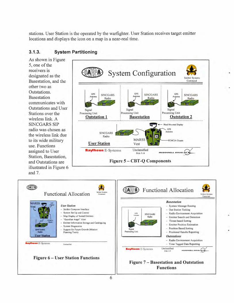
3.1.3. System Partitioning
As shown in Figure 5, one ofthe receivers is designated as the Basestation, and the other two as Outstations. Basestation communicates with Outstations and User Stations over the wireless linlc A SINCGARS SIP radio was chosen as the wireless link due to its wide military use. Functions assigned to User Station, Basestation, and Outstations are illustrated in Figure 6 and 7.
8 System Configuration
GPS GPS SINCGARS Radio
GPS
Signal Signal Signal
Soldier Systems Command
Process ing Unit Process ing Uni t Processing Unit
Outstation 1 ! Basestation Outstation 2 --------- ----------- -- ------ -- ---- _,_------- ----- --- --- -------- --- --- l.- --------- ---------- ----- ---- -----
SINCGARS Radio
User Station
Raytheon E -Systems
Vest
Unclassified Slide 5-14
PCMCIA Chassis
/
MCDONNELL DOUGLg.___
Figure 5- CBT -Q Components
Functional Allocation Soldier System~
Commnnd
~ Functional Allocation Sllldicr Sptcms
Comm ond
SINCGARS bdio
User Station
Raytheon E ·Sys tems
User Station - Sol dier Computer Interface
- System Set Up and Control
- Map Di splay of Soned Emitters
- "Guard ian Angel" Alen
- Emitter Information Storage and Catalogu ing
- System Diagnostics
- Suppon for Futu re Growth (Mission Planning Tools)
Unc lassi fied
Figure 6- User Station Functions
6
UPS
Signal Processing Unit
SINCGA RS Radio
Basestation - System Message Routing
- Out S tati on Tasking
- Radio Envi ronment Acqui si tion
- Emitter Search and Detection
- Threat-based Sorting
- Em itter Positi on Estimat ion
- Position Based Sorting
- Posi tional Results Reporting
Outstations - Radio Environment Acquisition
- T ime Tagged Data Reporting
Raytheon E·Sys tems Unclassified Slidc .S-1 5
/
IHCOONNitLL OOUOL'~
Figure 7 - Basestation and Outstation Functions

3.1.4. User Interface and Human Factors Analysis
During the system analysis phase, we discussed desirable CBT -Q characteristics with many warfighters[1]. The common "keys to success" were:
• Low false alarm rate
• Simple functionality and intuitive operation
• Range 3 -10 km
• Near real-time performance
• End system must be affordable
As a part of the user interface analysis task, several operational scenarios were developed. Each of the scenarios included behavior of CBT -Q system and its user interface. This analysis was widely accepted by warfighters and became a guiding principle in development of the User Station.
3.1.5. System Requirements
Based on the systems requirements analysis presented in sections 2.1.1 - 2.1.3, a detailed system requirements specification was generated and utilized to guide the system development. System Requirements Specification[2] document for the Combat Cueing System was drafted at the start of the program. The text below is an excerpt from the Overview Section of that document.
"CBT -Q System shall be a portable tactical information system which assists warfighters involved in small unit operations. CBT -Q shall detect a target emitter and " instantly" provide the warfighter with the emitter's location.
The minimal CBT-Q System shall be made up of three CBT-Q "Drop Packets" and warfighter' s User Interface Module, as shown in Figure 8. CBT-Q Drop Packets will be placed 3 to 10 km apart from each other in order to accurately detect the target emitter and calculate its location. Typical distances between target emitter and drop packets shall be on the order of 3 to 1 0 km. The User Station shall be capable of displaying and logging emitter locations.
7

Drop Packets conduct RF survey of Area of Interest: ·on command • on scheduled intervals • continuously
Figure 8 - System Operational Concept
There shall be two types of CBT -Q Drop Packets: Basestation and Outstation. Minimal CBT -Q System configuration shall have 4 subsystems: one Basestation and two Outstations, and one User Station.
Typical communication between the User Station, Basestation, and Outstation (Figure 9) will be accomplished as follows:
1. The Basestation shall accept tasking from the User Station. The tasking may typically include the target emitter type and geographical area of interest (i.e. a 5 by 5 kilometer area). If tasking is not received, default tasking or previously received tasking shall be used.
2. The Basestation and two Outstations shall acquire RF samples.
3. From captured RF samples, the Basestation shall perform target emitter detection.
4. If the target emitter is detected, the Basestation shall request signal timing information from Outstations.
5. Outstations shall respond with target emitter signal characteristics.
6. The Basestation shall accept target emitter signal characteristics and calculate the target emitter position.
7. The target emitter position shall be reported to the User Station if within the user's area of interest. .
8. Upon detection of a target emitter, the User Station shall alert the user and display the target emitter on the map and update the target emitter location log file .
9. The system shall periodically perform self diagnostics. Link failures , power disruptions, and self-detected functional failures shall be reported to the User Station.
1 0. The system shall return to step 1.
8

RF
CBT-Q ' Signal
Outstation """ GPS Signal
Tasking
Target Emitter
GPS Signal
~ CBT-Q
Outstation
Figure 9 - CBT -Q System High Level Data Flow
Each CBT -Q entity shall have a Global Positioning System Interface in order to determine the time and its own position."
Listed below are key requirements and guidelines.
Guidelines
• Highly Programmable - Supporting Easy Addition of New Signal Types
• Highly Flexible - Supporting Multiple Mission Scenarios
• Low Cost
• Low Power
• Low Profile
• Low Detectability - Minimize RF Emissions
Performance
• System Sensitivity - -105 dBm@ RF Input (all sites)
• Signal Type- frequency hopping in 30 to 88 MHz band
• Probability of Detect (Jaguar - up > 4s)- >95o/o
• Probability of False Alarm (SINCGARS/FM) - < 1 o/o
9
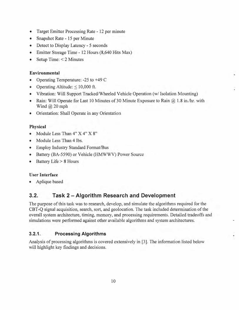
• Target Emitter Processing Rate- 12 per minute
• Snapshot Rate - 15 per Minute
• Detect to Display Latency - 5 seconds
• Emitter Storage Time- 12 Hours (8,640 Hits Max)
• Setup Time:< 2 Minutes
Environmental
• Operating Temperature: -25 to +49 C
• Operating Altitude: :S 10,000 ft.
• Vibration: Will Support Tracked/Wheeled Vehicle Operation (w/ Isolation Mounting)
• Rain: Will Operate for Last 10 Minutes of 3 0 Minute Exposure to Rain @ 1.8 in./hr. with Wind@20mph
• Orientation: Shall Operate in any Orientation
Physical
• Module Less Than 4" X 4" X 8"
• Module Less Than 4 lbs.
• Employ Industry Standard Format/Bus
• Battery (BA-5590) or Vehicle (HMWWV) Power Source
• Battery Life > 8 Hours
User Interface
• Aplique based
3.2. Task 2 -Algorithm Research and Development
The purpose of this task was to research, develop, and simulate the algorithms required for the CBT -Q signal acquisition, search, sort, and geolocation. The task included determination of the overall system architecture, timing, memory, and processing requirements. Detailed tradeoffs and simulations were performed against other available algorithms and system architectures.
3.2.1 . Processing Algorithms
Analysis of processing algorithms is covered extensively in [3] . The information listed below will highlight key findings and decisions.
10

• Jaguar signal was picked as a target signal due to its wide military use and frequency hopping characteristics.
• Jaguar' s information bandwidth is only 25 KHz. However, its signal bandwidth is tens of megahertz due to its frequency hopping nature across the entire 30 - 88 MHzband.
•
•
Conventional narrowband scanning search techniques are ineffective for detection of Jaguars due to its rapid frequency agility. (Figure 10)
Ideal search scheme is to monitor the entire signal
~ Signal Characteristics Frequency Hopping Radios
• Rapidly Changing Carrier Frequencies
• Pseudo Random Frequency Sequences
• Signal BW >> Information BW
.,
Unclassified
SoldicrS)·slcms CommJnd
Figure 10 - Jaguar's frequency hopping across 30-88 MHz alludes conventional narrowband search, detect, and track algorithms, which makes it a low-probability
of intercept radio
band (30-88 MHz) and look for energy bursts. This method was found to be impractical due to a large size of hardware required for its implementation.
• Ambush mode involves "parking" a 10 MHz search and waiting for the Jaguar to hop through. This too was found undesirable since Jaguar hopping sequence need not ever hop through the 1 0 MHz band.
• The approach chosen for scanning and detection was a hybrid one, which involves rapid searches in 30-88 MHz band in 10 MHz chunks (Figure 11). Specifically, CBT -Q stares between 30-40 MHz for 250 milliseconds, moves over to 40-50 MHz band where it acquires 250 millisecond worth of data, and so on until the entire band is scanned. This method was found to have a high probability of detection for nearly all Jaguar hopping patterns.
• Once the signal is detected, the geolocation calculation uses time difference of arrival method, which is a function of the signal arrival time at each
Signal Detection ('H'I-(j /nnovalion
Proprictnry
Soldi~ r S)'I ICOl5
CommMd
Figure 11 - CBT-Q Algorithm relies on rapid data acquisition across the entire 30-88 MHz band. A sliding
10 MHz scan window covers the entire band in 1.5 seconds. This method has a high probability of detection
for most hopping sequences.
11
•
•
sensor (Basestation, Outstation) and sensor locations. The critical algorithm involves calculation of time of arrival. Two methods were identified: correlation and Raytheon's Baud Phase algorithm.
Correlation involves passing large amounts of data from Outstations to Basestation where timing differences are calculated. This method was rejected due to was rejected due to a requirement to pass large amounts of data from Outstations to the Basestation. There were several serious drawbacks to this method: (a) amount of time required to send sufficient amount of data was in estimated to be in tens of seconds, and (b) Outstations would flood the RF spectrum with RF energy during data transmissions, thus increasing their own probability of being detected.
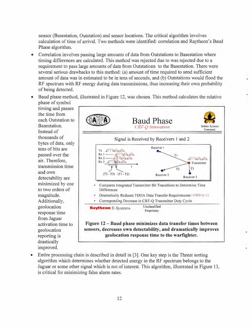
Baud phase method, illustrated in Figure 12, was chosen. This method calculates the relative phase of symbol timing and passes the time from each Outstation to Basestation. Instead of thousands of bytes of data, only tens of bits are passed over the air. Therefore, transmission time and own detectability are minimized by one to two orders of magnitude. Additionally, geolocation response time from Jaguar
Baud Phase CBT-Q Innovation
Signal is Received by Receivers 1 and 2
Receiver I Tx~
Soldier Systems Command
Rx I --- ----~
Rx 2 ------~1 1 1 1 1
Rx 3 __Qjl"ljl ~
)~ t
Transmitter
T3
(T2 - T3) (TI- T2) • Receiver 2 Receiver 3
• Compares Integrated Transmitter Bit Transitions to Determine Time Differences
• Dramatically Reduces TDOA Data Transfer Requirements (I 000 to I )
• Corresponding Decrease in CBT -Q Transmitter Duty Cycle
Raytheon E -Syste rns Unclassified Proprietary
activation time to Figure 12- Baud phase minimizes data transfer times between geolocation sensors, decreases own detectability, and dramatically improves reporting is geolocation response time to the warfighter. drastically improved.
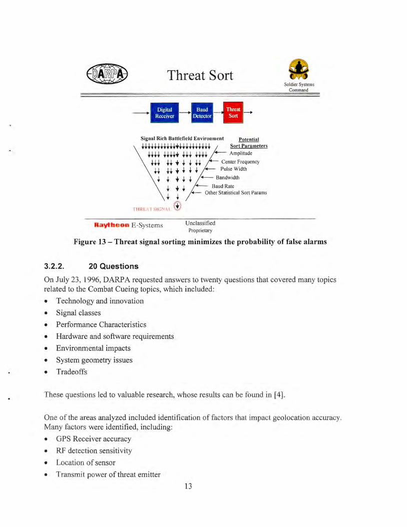
• Entire processing chain is described in detail in [3]. One key step is the Threat sorting algorithm which determines whether detected energy in the RF spectrum belongs to the Jaguar or some other signal which is not of interest. This algorithm, illustrated in Figure 13, is critical for minimizing false alarm rates.
12
Threat Sort
--· -Signal Rich Battlefield Environment Potential
ttttttttttt"+tttttttttt Sort Parameters
tttt tttt"+ t~t tttt '+--- Amplitude
ttt tt -+ t t tt Center Frequency tt tt -+ t t t ~ Pulse Width
t t -+ t t +--- Bandwidth
t -+ t .....__ Baud Rate t t ~ Other Statistical Sort Params
Til REt\ T SIG NAl @
aythe on E-Systems Unclassified Proprietary
Soldier Systems Command
Figure 13- Threat signal sorting minimizes the probability of false alarms
3.2.2. 20 Questions
On July 23 , 1996, DARPA requested answers to twenty questions that covered many topics related to the Combat Cueing topics, which included:
• Technology and innovation
• Signal classes
• Performance Characteristics
• Hardware and software requirements
• Environmental impacts
• System geometry issues
• Tradeoffs
These questions led to valuable research, whose results can be found in [4] .
One of the areas analyzed included identification of factors that impact geolocation accuracy. Many factors were identified, including:
• GPS Receiver accuracy
• RF detection sensitivity
• Location of sensor
• Transmit power of threat emitter
13

• Duration of emission
• Signal to noise ratio of the emitted signal
• Number of hopping pulses detected and processed
• Multipath
Another question dealt with the choice of the bus standard chosen for CBT -Q hardware architecture. Tradeoff analysis (Figure 14) considered several critical criteria and chose Small PCI standard.
8 Question #20, part la: CBT -Q Module Card Standard Tradeoffs oldicr System
Command
• Small PCI is the card standard of choice - PCI bus bandwidth (133 MB/sec) - PCMCIA size
Evaluation Criteria
Fits inside 4"x4"x8" Volum
Meets Target Weight
Commercial "buy-in"
Field interchangeable
Rugged
Digital/Analog Isolation
25 MB/s Transfer Rate
Future Vision
Unclassified
mostly meets criteria c=J partially meets criteria
doesn t meets criteria
Figure 14- Small PCI standard met most of the evaluation criteria
3.2.3. Simulation
Extensive simulation was performed in order to predict the performance of the system. Results of this study are shown in [5]. Simulation involved many scenarios with varying number of factors that influence geolocation accuracy. These factors include transmitted power, geometry of sensors, and others.
14

Figure 15 shows the typical impact of geometry on the system geolocation accuracy. Two cases are considered. In a preferred case (left figure) , the target emitter is surrounded by CBT -Q sensors (small blue circles). In a less preferred case, the target emitter is not surrounded by sensors. Each ellipse represents an 80o/o probability curve for detecting the target emitter. Specifically, if the emitter location were in a center of the ellipse, the CBT -Q system would geolocate the emitter inside of the ellipse 80% of the time with an approximate accuracy of 1 00 meters.
ELComp - BUA TxPower(W): 1.5 EL Comp - Scout TxPower(W) : 1.5
~ ~ ~ LJ l'i ~ \ I 0 r_; 5 ~ v {/
5
~~ ~ l ~1 8. 8. .. La b j 4 \1 ( Q.
4 _g .... ..... .....
3 ~ ~
II v ., $ J U Built Up Area I ....
~ 3 • l.SW t!! J Avg. ~ 7 Hops "' 2 I Srout I .,
r l l L I.S W :5 :5 00 .. Avg. ~ 7 Hops
0 2 '"' 0 1
~ .i:i e a Q. 0 1 ~
! ! -1
0
0 1 2 3 4 5 6 7 8 0 1 2 3 4 5 6 7
(km) pairs: [1 2; 2 3; 1 3] 29-0ct-96 ELERR4 (km) pai rs : (1 2; 2 3; 1 3] 29-0ct-96 ELERR4
Proprietary Data Proprietary Data
Figure 15- Surrounding target emitter with CBT -Q sensors leads to improved geolocation accuracy.
3.3. Task 3 - Hardware Development
3.3.1. Requirements Analysis
The first part of hardware development included analysis of required resources in order to execute specified Baud Phase based geolocation algorithm. Results of this analysis are shown in [6] .
Initial chassis concept is illustrated in figure 16. The concept was based on spatial estimates required to meet demanding processing requirements, illustrated in figure 17. In order maximize the processing power per volume
Chassis ____; Interchangable Small PC! Circuit Cards
""'-------
'------ Front Panel
Figure 16 - Initial concept for Combat Cueing Sensor packaging was based on a 4"x4"x6"
chassis
(cubic centimeters), a just-released Texas Instruments TMS320C62 digital signal processor (DSP) was chosen.
15

ED Signal Processing Unit Processing Analysis
25.6 M samples/sec
Soldier Systems Command
TUNE DATA
BAUD PHASE
TOTAL PROCESSING TIME (SIX- 10 MHz BANDS) = CHANNEL and DETECf PROCESSING + TUNE and TDOA PROCESSING
NOTE: Tune and TDOA Processing Requires Tune Data
/ Raytheon E-Systems Unclassified
Proprietary Data IHCDONNELL DOUGL'~~
Figure 17- RF detection and geolocation processing requirements
The system requirements for the Basestation and Outstation [7] and User Station [8] were derived based on overall system specifications.
Figure 18 illustrates the architecture for the Basestation and Outstation sensor.
Termed CBT-Q Module, the module contains all of the necessary functions and interfaces to perform geolocation detection and geolocation functions.
CBT-Q Module
I
1 Tamper 1/F
Serial Ports (4):
: DFI/F# I 1 OF 1/F #2
~ - - -- - - - - - - - - ·- - - - - - - - - - - - - - - - - - - - - - - I •Timckccping/Acquisilion ComroUGPS ln1crf.1cc
New Design OcoTs
Figure 18 - Basestation/Outstation modules and Constituent Subsystem Electrical/Data Interfaces
16
r-- --------- ---------- - ----------------------- ----- --- -----1 I
Radio 1/F
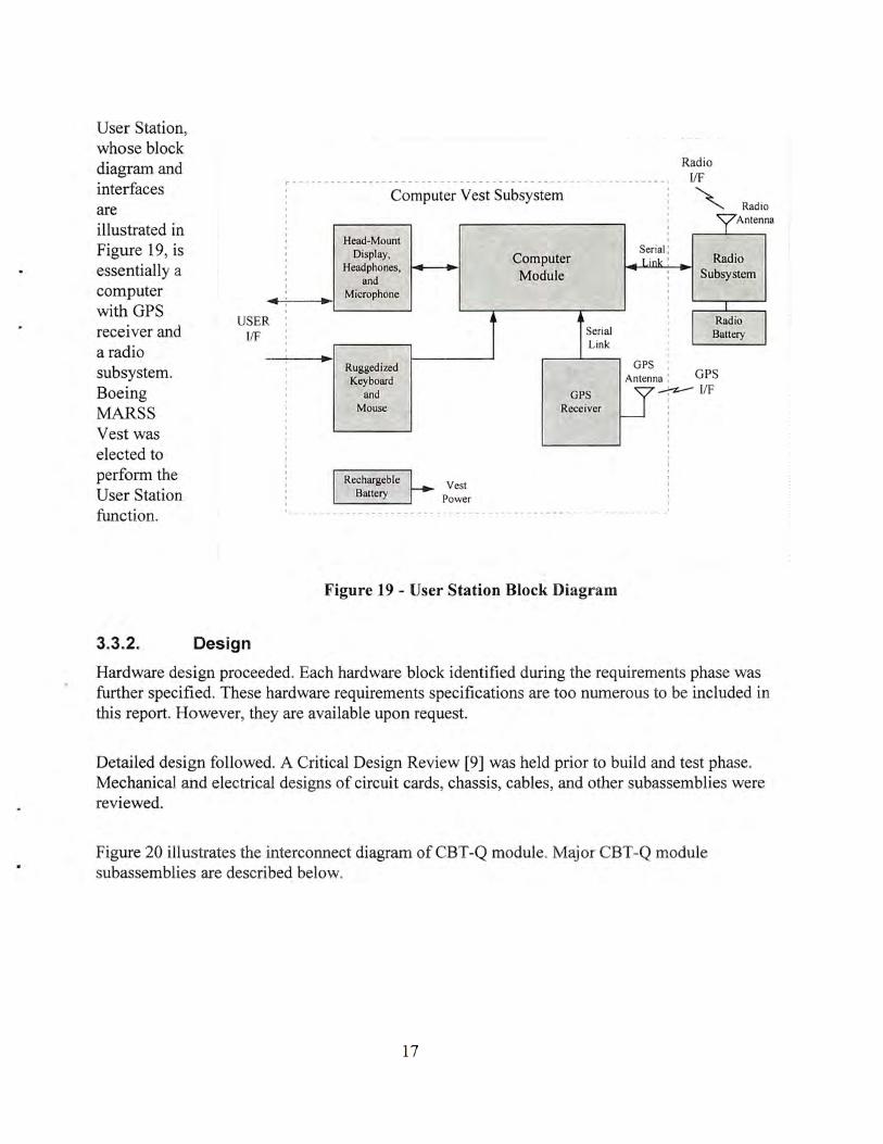
User Station9
whose block diagram and interfaces are illustrated in Figure 19, is essentially a computer with GPS receiver and a radio subsystem. Boeing MARSS Vest was elected to perform the User Station function.
Computer Vest Subsystem
" Radio I
?Antenn I
a
3.3.2.
USER Iff
Design
I
I
... :
I
I
I
I
Head-Mount Display
Headphones, and .. Microphone
.. Ruggedized Keyboard
and I' Mouse
Vest Power
Computer Module
• Serial Link
GPS Receiver
Figure 19 - User Station Block Diagram
Serial : Radio Link ' .
I Subsystem I
I Radio
I Battery
I
GPS I
Antenna : GPS
u~I/F
I
I
Hardware design proceeded. Each hardware block identified during the requirements phase was further specified. These hardware requirements specifications are too numerous to be included in this report. However, they are available upon request.
Detailed design followed. A Critical Design Review [9] was held prior to build and test phase. Mechanical and electrical designs of circuit cards, chassis, cables, and other subassemblies were reviewed.
Figure 20 illustrates the interconnect diagram ofCBT-Q module. Major CBT-Q module subassemblies are described below.
17

7/23/97
J1
GPS (Coax)
1.1 .3.6
J6 J2 J7 J4 J5
Figure 21 - CBT -Q Module Interconnect Diagram
3.3.2.1. Chassis
Critical characteristics of the CBT -Q Chassis, illustrated in Figure 21, are listed below:
• Miniature construction: 6.6" X 6" X 3.8"
• Weighs only 2.1 pounds
• 1 0: 1 space and weight reduction over VME
• 12 card slots: 10 small PCI and2 PCMCIA
• Environmentally tight-water resistant to 1m
• Conduction cooled
RF antenna
1/0 connectors
HMM RF antenna,
Power switch Battery
OF mode coax power module
Figure 20- CBT-Q Module Chassis Features
18
J3

• Embedded MPE-I™ Miniature PLGR GPS Receiver Engine
• Embedded GPS Antenna
• Integrated RF antenna
• Battery or HMMWV powered.
• Other integrated power conditioning adapters are available.
• Ideal for dismounted, airborne, and covert applications
• A suite of Small PCI circuit cards available for customized applications.
The chassis (Figure 22) contains all essential functions required for your application: a 12-slot motherboard, featuring 10 small PCI slots and 2 PCMCIA slots, embedded GPS receiver engine, GPS and RF antenna and associated wiring. The chassis is rugged and environmentally safe. The assembled unit can be immersed under water or operated in a desert sun.
The chassis is powered by an interchangeable HMMWV Adapter or a Battery Pack (Figure 23).
Power connector
Input attenuator
PCI is a credit-card size, open standard featuring 133 megabyte per second data transfer capability. PWBs are two sided.
Figure 22 - CBT -Q Module Chassis
Figure 23 - CBT-Q Chassis' HMMWV Power Adapter (top) and Battery Pack (bottom)
3.3.2.2. Small PCI Cards
Each Small PCI card has a single or a dual (Figure 24) printed wiring board (PWB) construction. Small
19
Figure 24 Card construction includes two circuit cards, shields, and housing

PWBs are sandwiched by top and bottom cover. For RF applications, covers may also have builtin compartments for RF shielding and isolation. Cards are designed to provide an efficient thermal path from PWB to the circuit card housing. The expander moves the heat from the housing to the chassis.
Combat Cueing program has developed and or integrated the following circuit card assemblies (CCAs):
• RF - IF CCA (Figure 25). This card is a wide band tuner operating in the 3 0 - 8 8 MHz band. It outputs 1 0 MHz wide intermediate frequency (IF) digitized to 12 bits of resolution. Control is accomplished over the PCI bus.
• Embedded Controller Card (Figure 26). Miniaturized through multi-chip module technology, this COTS product features all of the characteristics of a Pentium based personal computer.
• Processing Element (PE) Card (Figure 27). Based on a TMS320C62 DSP, the card accepts wideband IF and can be programmed to perform a wide variety of digital signal processing applications including spectrum analysis, search, demodulation, and others. The card features a digital downconverter, 16 megabytes of IF shapshot memory, and PCI interface capable of bus mastership.
Figure 25 - RF-IF Circuit Card Assembly
Figure 26- This Pentium-based Embedded Controller card was never delivered by the vendor.
• Timing, Acquisition, and GPS Card.
An alternate card from Ziatech was selected an interim solution.
Known as TAG, this card provides an interface to the GPS engine. It also contains additional EEPROM, and circuitry for synchronizing RF acquisition with GPS.
Figure 27- TMS320C62 portion of the PE CCA • Quad Serial Card. This COTS card provides four
RS23 2 connections to the external world.
• Other PCMCIA Cards. Two of the 12 PCMCIA slots can house many of the commercially available cards such as Ethernet card, Modem, and others. A PCI-to-PCMCIA bridge chip on the motherboard allows any bus master to access these PCMCIA cards.
20

3.3.2.3. Thermal Characteristics
CBT -Q chassis is conduction cooled. Covered by heat fins on 5 of the 6 sides, the chassis has a 0.4 degree C per Watt rise when no external air cooling is present. External forced air cooling can improve the thermal performance by almost an order of magnitude.
3.3.3. Build, Integration and Test
Combat Cueing System hardware (Figure 28) was built and tested in accordance with requirements specifications. Exceptions and workarounds are noted below. Some of the workarounds, while not technically preferred, were chosen based on cost considerations. Higher performance implementations were identified but required funding levels that were not available.
3.3.3.1 .
Out Station 1
SINCGARS Radio
User Station
Raytheon
GPS Antenna
J
CBT-Q Module
SINCGARS Radio
Base Station
Unclassified
GPS Antenna SINCGARS J Radio
CBT -Q Module
Out Station 2
Figure 28- Combat Cueing Hardware
RF-IF CCA
• Initially intended to be a single circuit card assembly, RF~IF CCA was designed on two circuit boards due to its complexity and packaged in one 0.5" housing.
• Sensitivity and dynamic range experienced significant degradation during testing. Analog board was separated from the digital board and housed separately to minimize interference.
• Sensitivity of -105 dbm was not achieved. Instead, -90 dBm was measured in the laboratory environment. This reduction of sensitivity is estimated to have a 50o/o to 70% impact in CBTQ sensor range.
• Spur free dynamic range was measured around -65 dB vs. the goal of -75dB.
21

3.3.3.2. PECCA
• Initially intended to be a single circuit card assembly, PE CCA was designed on two circuit boards due to its complexity and packaged in one 0.5" housing.
• XILINX field programmable gate array (FPGA) PCI Core did not perform as advertised. Consequently, PCI Initiator function was eliminated. The impact of this change was sign
• C60 Errata sheet identified 45 design problems with TMS320C62 microprocessor. Major problems included loss of 2M byte fast-memory access, unreliable emulator port, memory switching problems. This was a major blow to the CBT-Q performance. The solution included jumpering of additional 256K synchronous burst RAM, lowering the clock speed from 200 MHz to 11 OMHz, and elimination of pipe lined operation. Overall impact was a loss of performance by an approximate factor of 7x. Using today's errata free versions of 'C62 additional performance improvement of 2x could likely be achieved.
• Due to the significant modifications required for enabling PE CCA, only one instead of six CCAs were built and tested per module.
3.3.3.3. Embedded Controller
• Initially a Megatel COTS board was selected to perform this function. The vendor slipped delivery by almost 12 months. An alternate solution was implemented. The new card was also COTS, but came in a Compact PCI format instead of Small PCI form factor. The card is manufactured by Ziatech.
• This modification required a chassis insert and a flex cable, as shown in the Figure 29 .
• In order to keep the height of the Ziatech card to a minimum, processor heatsink and some connectors had to be removed. These changes, along with the Ziatech-to-PCI cable presented some serious challenges during debug test and integration phase.
3.3.3.4. CCA
TAG
• TAG CCA met majority of its design requirements
• ·Card-to-card timing
~ Megatel EC Availability
• New delivery date is Q 1 1998 (March 31 ?)
• Temporary replacement identified - Compact PCI Embedded Controller
- Qty 1 due on Jan 31
Sddicr Systems Commond
Flex Cable
• Recommendation: Switch to Compact PCI now ! ...... SAtllll ..... Unclamftod
Figure 29 - Mega tel Small PCI Embedded Controller was replaced by Ziatech Compact PCI Embedded Controller.
This change led to some chassis modifications.
22

differences, critical to Combat Cueing performance, were measured within 50 nanoseconds, which is above expectations.
• TAG CCA' s analog-to-digital clock output had too much distortion and required an external band pass filter.
3.3.3.5. VEST
Instead of the MARSS vest, it was agreed that Boeing would deliver a derivative of Special Operations Combat Management (SOCM) Vest. Capabilities of standard SOCM Vest and Combat Cueing baseline are shown below. SOCM Vest is pictured in Figure 30.
Table 1 -Special Operations CBT -Q Management System Specification
SOCM SPECIFICATION I OPTIONS COMBAT CUEING CONFIG. Operating System Windows™ 95 Windows™ NT
Display Seattle Sight Systems Hand Held 640x480 or Kopin 640x480 Kopin 640x480
Processor 150 MHz Pentium MMX, upgradeable to 200 and 233Mhz 150 MHz Pentium MMX
Memory 64 Mbytes 64 Mbytes
Weight 11.1 Lbs. basic system, 16.5 Lbs. with PRC-143 radio and GPS 8.9 Lbs. without GPS or Radio
Video Output VGA and SVGA Compatible VGA and SVGA Compatible
PCMCIA Slots 3 Total, 2 Type II and one Type III Disabled Due to Windows™ NT
Hard Disk Drive 340Mbyte PC Card ATA Hard Drive 340M byte PC Card AT A Hard Drive
GPS System Rockwell SOLGR, also PLGR compatible PLGR (One total for all systems)
Battery Life 4 to 6 hours 4 hours ea.
Battery 6 Amp-hour Lithium Ion Polymer 4 Amp-hour Lithium Ion
Short Range Proxim RangeLAN2 Wireless LAN Card N/A Communications
Long Range Hughes AN/PRC-143 Hand-held Multi-band radio, compatible SINCGARS interface through Serial Cable Communications with AN/PRC-117 and SINCGARS and Raytheon £-Systems Software
23

SINCGARS RADIQ_ PACK
SOCM COMPUTER ASSEMBLY
LITHIUM ION BATTERY
\
HMD
I MOUSE
~PLGR
Figure 30 -User Station Vest and Associated Components
The Boeing Company provided Raytheon E-Systems four SOCM systems each configured with the SOCM Computer Assembly, Kopin HMD, mouse, keyboard, vest, two lithium Ion batteries, and a battery charger. The SOCM System is loaded with the User Station Software and interfaced with a SINCGARS radio and PLGR to be used as a Combat Cueing User Station
3.3.3.6. Radios
Four SINCGARS Radios were built along with Vehicular Amplifier Adapters which boost the radio power to SOW. Rechargeable batteries for dismounted operation were also obtained.
3.3.3.7. PLGR GBS Receiver
A military version of GBS receiver was obtained from Rockwell. PLGR is Y2K compliant. PLGR is attached to CBT -Q Module motherboard. External GBS antenna is embedded in the CBT -Q Chassis.
3.4.
3.4.1.
Task 4- Software Development
Requirements Analysis
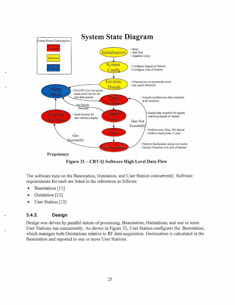
During this phase of the program, software requirements were established. At a system level, CBT -Q software function is illustrated in the Figure 31. Further high level analysis can be found in [1 0].
24
ystem Power Consumption
Proprietary
System State Diagram
user interface display
• Boot • Self Test • Establish Links
• Configure Signals oflnterest • Configure Area of Interest
• Characterize environmental noise • Set search threshold
• Acquire synchronous data snapshots at all locations
Search data snapshot for signals matching signals of interest
• Perform tune, filter, FM demod • Perform baud phase, if used
• Perform Geolocation using tune results • Decide if location is in area of interest
Figure 31 - CBT -Q Software High Level Data Flow
The software runs on the Basestation, Outstation, and User Station concurrently. Software requirements for each are listed in the references as follows:
• Basestation [11]
• Outstation [12]
• User Station [13]
3.4.2. Design
Design was driven by parallel nature of processing. Basestation, Outstations, and one or more User Stations run concurrently. As shown in Figure 32, User Station configures the Basestation, which manages both Outstations relative to RF data acquisition. Geolocation is calculated in the Basestation and reported to one or more User Stations.
25

System Data Flow (High Level)
Raytheon E-Systen1s Unclassified
Figure 32- Basestation manages Outstations
Soldier Systems Command
The parallel nature of processing is illustrated in Figure 33. After tasking each of the Outstations to acquire RF data, Basestation itself also acquires RF data and performs search and detection for threat emitters. If a threat emitter is spotted, Basestation requests baud phase information from Outstations. Geolocation is calculated using three sets of baud phases and sensor locations. Location of threat emitter is then reported to the User Station.
26

Outstations
Raytheon E-Systcms Unclassified
Basestation
Soldier Systems Command
User Statio11
Figure 33 - CBT -Q Parallel Processing Timing Sequence
High level software design, illustrated in Figure 34, is described in [14]. Three Computer Software Configuration Items (CSCis) were defined:
• Base/Outstation Embedded Controller (EC) CSCI, which runs on the Pentium based controller
• Base/Outstation Processing Element (PE) CSCI, which runs on TMS320C62 DSP
• User Station CSCI, which runs on SOCM Vest.
3.4.2.1. Base/Outstation
Base/Outstaion software was
CSCI Breakdown
EC PE
(Embedded Controller) (Processing Bement) Controls process DSP based software •Radio ·RF detection •GPS/PPS •Geolocation •Message switcher •Status manager •Power management
I Raytheon E-Systems
User Station
Soldier Systems Command
User interface •Radio •Mapping system •GPS
Figure 34 - Software divided software into three Computer Software Configuration Items (CSCis)
implemented in three "builds", each adding a maturity level to the previous baseline. Build 1 covered low level interfaces, while Build 3 integrated Geolocation. Figure 35 shows the high
27

level breakout of software.
Base/Outstation Software Low Level Decomposition Soldier Systems
Command
Base/Out Station PE
0 Buildl
• AGC Env. Sampling · Acquire/Setup SW Dev. Env. • Start/Init o Floating Point Emulation o RF Collection o AGC • Channelization o Normalization • Noise Floor
[J Build 3
• Quick Search • Mainloop · BIT
0 Build 2
• Slow Search Detection
• DDC Control o Delay Multiply • Multipath lgorithm o FM Demod • Baud Phase Calculation o Pulse A ociation o Emitter Location
• Adjacent Channel 0 Enhanced BIT • Slow Search Nois~ Floor
Base/Out Station EC
0 Build l
[J
• Acquire/Setup SW Dev. Env. o Serial Board Driver · CPU Driver • Flash Driver o SelfTest o Start/ Init
• GPS • Network Interface [J • Shared Software Build 3
c Flash File System · User Task Manager • State Manager • System Status Tablle • Message Logger • Status MGR
Build 2 o Test IF MGR- User
o RF Detection Manager o SelfTest Manager o Test 1/ F Manager Base/Out
~------- Unclassified -----Figure 35- Basestation and Outstation CSCis were built in three stages
Base/Outstation EC software was developed using Rational Rose design tool. Programs are coded in C++. V x Works operating system is employed.
PE Software runs on 'C62 processor. C and assembly languages were employed.
3o4o2.2o User Station
User Station software was developed on SOCM Vest in C++ running under Windows NT environment. Design is made up of functions listed in Figure
28
User Station Software (Boeing Subcontract)
• User Station Controller
• Screens • Tasking of Base Station • Receive Hits from Basestation o Basic Replay Capabilities • G PS Interface • Station/System Status
Figure 36- User Station software functions

36.
The most critical aspect of the design was the user interface. At the onset, several user screens were prototyped to highlight the desired features .
The User Station (Figure 37) provides a user interface to control the operations of the Combat Cueing System. It also records the data so analysis of the mission can be done later. The User Station Software initializes when the user powers up the hardware in a normal Combat Cueing System configuration. When activated and running a mission the User Station Software displays the CBTQ User Station Main Window with a mission running. Enemy detections are triangles and friendly detections are square in shape
Status Bar Enemy
Figure 37 - User Station Main Window
29

3.4.3. Software Code, Integration and Test
The primary impact on this phase was the hardware limitations PE hardware described previously. EC and User Station software were mostly implemented as planned.
3.4.3.1. PE Software
•
•
•
•
•
•
Quick Search was eliminated from PE Software. The primary purpose of this function was to lower the overall power consumption. As shown in the Figure 38, during low emitter activity times Quick Search was going to allow CBT-Q module to look for RF energy and, if no energy resembling frequency hopping radios was detected, go to a standby power mode. Additionally, it was
%of Max. Processing
Power
100%
50%
Question #20, part 1 a: Power Options - Continued
Pre-Mission Standby Mode
In Mission High Emitter
Activity
Time
CBT-Q Module will be designed to adapt its power usage to the environment activity.
Raytheon E-S '> LL·ms Unclus11ied
Figure 38- PE Hardware problems caused deferment of Quick Search algorithm development. This in turn led to
elimination of low power mode during low emitter activity.
shown by analysis that Quick Search increased the probability of detection by allowing CBTQ to more frequently sample RF environment before the hopping signal went active.
Low power mode, also known as "snooze" mode was also eliminate, since it only made sense in context of Quick Search.
Since 5 of the 6 PE cards were eliminated from the hardware baseline, it was decide to employ a single card in a less preferred 1 0 MHz "ambush" mode.
RF-IF card control, originally planned for PE card, was moved to EC software since PE could not write over the PCI bus into RF-IF registers. This meant that EC Software had to be involved in both tuning and automatic gain control (AGC) processing.
Geolocation processing was moved from PE to EC since PE integration went very slowly due to errata problems and their fallback solutions, such as NOOP (no-operation) insertion.
In order to speed up RF Detection, several sections of code were optimized or simplified . Techniques included use of assembly language, floating point operation approximations, and reduction ofRF analysis window from 250 milliseconds to 125 milliseconds.
30

3.4.3.2. Embedded Controller Software
• EC software met most of its requirements objectives
• Additional functionality moved over from PE software included RF-IF card control, tuning and AGC support, as well as geolocation
• EC was also tailored to operate with a single PE card instead of six
3.4.3.3. User Station Software
User Station software mostly met or exceeded its requirements.
3.5. Task 5- System Test and Evaluation
The objective ofthis task was to integrate, test, and evaluate CBTQ system performance. Due to late availability of hardware, field evaluations were performed incrementally at a sub-function level. Four primary subfunctions were tested:
• Radio Network
• Timing Accuracy
• User Station
• RF Detection
3.5.1. Radio Network (Figure 39)
Ability to send data packets over the SINCGARS radio link was tested at AP Hill. Test results showed that:
Figure 39- Radio Network testing at Ft. AP Hill verified that Basestation (BS), Outstations (OS), and User Station (US) could
communicate over SINCGARS SIP link if placed in locations highlighted on the map. Yellow lines indicate verified links~
• Radio network communications in distance and foliage settings is sufficient for the needs of the system
• Locations chosen for the Fort A.P. Hill final demonstration activity can be supported for network communications
• Highest reliable radio baud rate for data communications is 4800
• Vehicles in motion generally able to communicate as long as line of site realized
31

• Effective baud rate of SINCGARS SIP radio is much lower than expected, mostly due to 300 -400 millisecond carrier ramp-up/down time. Consequently, a 60-byte message takes nearly 0.5 seconds to transmit, reducing the effective baud rate to approximately 1000 baud.
For more information Radio Network testing see test results document [16].
3.5.2. Timing Accuracy
A timing accuracy test was performed to measure the ability of two TAG cards to keep track of time. Minimal absolute time difference between sensors is critical to geolocation accuracy. For every 3 nanoseconds of timing mismatch, additional error of 1 meter may occur in calculation of target emitter location.
A simple the test, illustrated in the Figure 40, used a common GPS receiver which provided a 1 pulse-per-second input to two TAG cards. Each TAG card was
Timing Test
Event_.. Event Time I TAG Strobe I
r-+ Cardl
Event GPS - I pulse-per-second Strobe Receiver ,; Measurement
Event
~ TAG Strobe 2
Event Card2 Time 2 _.. ,; ,;
E T
vent ime ere nee Diffi
._.
Figure 40- Timing accuracy test exceeded expectations. 30 nanosecond difference was measured between two TAG cards' Event Strobes. This suggests that the geolocation error caused by CBT-Q sensor internal time keeping will
only be about 10 meters.
programmed to generate an Event Strobe at the same time. (Event Strobes are used for synchronization of RF data acquisition and baud phase calculations. Each sensor has aT AG card.) Event Strobes were measured for synchronicity.
The findings exceeded expectations. Differences of 100 nanoseconds were expected. Nominal differences of 3 0 nanoseconds were measured.
3.5.3. User Station
During the period of 21 -23 September 1998, the Combat Cueing (CBTQ) project performed testing at the Fort A.P. Hill test facility. This testing was intended to:
• Confirm operations of system hardware components (module, radios, vests, cabling) in a field environment
32

• Verify Base Station (BS) installation in the HMMWV (including mechanical, mount, power cabling, radio cabling, and GPS antenna cabling)
• Verify BS to User Station (US) connectivity via radio and direct connect interfaces
• Verify ability of the US to command the BS and receive information from it
In addition to the above goals, the Outstation (OS) radio network and status related software would be tested by installing it on laptop computers and operated in effect as OS simulators. The OS units would then participate in the radio network, accept system control commands, and report status information to the BS. To facilitate the simulation of normal system operations, test data scripts on the BS were initiated by the US. These test scripts sent emitter detection and location reports to the US units.
During periods of the testing the User Station was able to connect to the Base Station via both the radio and direct connect interfaces. During these connection periods, the US was able to successfully command the Base Station software to perform system startup functions and was able to receive system status information from the BS. This system status information consisted of system components (BS and OS) and their position information. The US map did display the correct icons for the BS and OS units in their correct locations. The US unit icons did not appear on the US map. This may have been due to an incorrect GPS receiver setup. The test data scripts executed successfully causing simulated emitter detection and location data to appear on the maps in the planned locations. For more details see [17] . User Station test is illustrated in Figure 41.
Figure 41 -User Station test was performed at Ft. AP Hill in three positions. Threats were simulated by the Basestation and sent to User Stations, where they were displayed.
US·2
ThrE!at-2 pos-2
Threat·2 pos-1
Drop Zone
BS
jj
Base-J
OS-1
Laser Range
OS-2

3.5.4.
3.5.4.1.
RF Detection
Laboratory Tests
Ability to detect RF emissions of Jaguar radio was first demonstrated in the laboratory environment. The test involved a Panther Radio (Figure 42) operating in Jaguar mode using a programmable frequency hopping sequence. The radio operated in a low power mode and was connected to the CBT -Q Basestation module ' s antenna input with a coaxial cable through a variable attenuator.
Despite several software optimizations, CBT -Q Basestation ran RF detection in about 1 7 seconds, or about 9 times slower than predicted. Majority of this degraded performance is attributable to PE CCA errata problems described in section 2.3.3.2. Consequently, the algorithm was modified to process 125 millisecond snapshot of RF energy rather than 250 milliseconds as originally specified. Although reduced RF snapshot time incurs small reduction in probability of detect, it reduces the detection time 14.3 seconds.
Recognizing that the degradation in RF detection also impacts the Geolocation response time, a message was
Figure 42- Panther Radio is compatible with the Jaguar. It optionally operates in a high
power 20W mode.
added from the Basestation to User Station to indicate the detection before the actual geolocation icon is displayed.
Lab tests were conducted in the "ambush" mode by monitoring a single 10 MHz band and letting the Jaguar signal hop through the ambush band. Tests were conducted at all 6 bands.
3.5.4.2. Field Tests
RF Detection was performed at Ft. AP Hill in March 1999. Two fully populated CBT -Q Modules were used in testing. The primary objective of the test was to:
1. Demonstrate the RF detection capability of the CBT -Q system
2. Measure the maximum RF detection distance of the CBT -Q system
3. Measure the minimum signal level required for a successful RF detection
4. Identify Combat Cueing system issues
5. Determine the ability of the RF detection algorithms to discriminate between a Panther radio and a SINCGARS radio.
6. Identify equipment locations and resources required for the Geolocation field test and demonstration.
34

The test results are described in [18], and summarized in Table 2 and Figure 43 .
Table 2-Ft. AP Hill RF Detection Test Summary
Objective Results
1. Demo RF Detection This was successfully demonstrated on two CBT -Q modules.
2. Max Detect Distance Successful to 8.5 km but foliage and terrain masking caused failures in three locations closer in.
3. Min Detect Level Successful to -80dBm
4. Identify Issues CBT -Q modules exhibited failures due to apparent thermal problems.
5. RF Detect Algorithm This objective was not met. SINCGARS hopping mode was Discrimination not available.
6. Prepare for Geolocation Locations and equipment were identified and tested. Demo
Figure 43 - Yellow dots indicate locations from which the Basestation successfully detected Panther transmissions. Detection failures (red dots) occurred in low lying, foliage rich
areas with reduced line-of-sight to the Basestationo
35

3.6. Task 6 - Demonstrations
The purpose of this task was to demonstrate geolocation in the laboratory environment. All field tests were performed at Ft. AP Hill, Virginia. Initial testing of the architecture validated the wireless network approach over SINCGARS radio.
The first test was performed in May of 1999. Results are summarized in Figure 44.
-~~LPI Geolocation Ft. AP Hill, May 1999 - Demonstrated LPI geolocation - 1 km accuracy (0.5km accuracy expected) - ofnvare & hardware bugs uncovered - Tracked outstations on the move -Multiple LPI detections - No fa lse alarms - Detection: 1-1.5 econds - Geolocation: 1 seconds
Figure 44- The First CBT-Q Geolocation Demonstration
The second geolocation demonstration, illustrated in Figure 45, corrected some of the algorithm errors and improved the accuracy to 250 meters, a 4x improvement over the initial demonstration. All antennas were mounted on commercial vehicles, resulting in a lower sensitivity.
36

~~~!!:~~--~·· LPI Geolocation
Ft. AP Hill, June 1999 - E
·1 00
OUTO
·-.. ____ ,_150m···· •••
...
BASe
Ft. AP Hill, June 1999 -Demonstrated LPI geolocation on the move -250m accuracy - Commercwl vehicle installation
Tracking a Moving Target
• The ye llow borderline approximates the 250 m distance a-. ay frorn the true location of th\! threat t:mitter • Majority of the geolocations fall within the boundary. There lore. tatistical accuracy lor this geometry is +/-250 meters
••• •••• ~·:!1som ·· .... UllOm • ,,
OUT1
fOGO 1100
Figure 45 - The second CBT -Q demonstration yielded a 250 meter geolocatioon accuracy~
37

The third and final demonstration took place in November, 1999, is illustrated in Figure 46. This demonstration demonstrated a 2.5x improvement in the sensitivity.
LPI Geolocation Test Ft. AP Hill, November 1999 -Commercial vehicle installation - 2.5X improvement in detection range - 25() m accuracy (unchanged) - I CCA RS failure prevented test completion -Additional improvements e.>.pected with RF card spur .ftxes
Figure 46 - The third CBT -Q Geolocation test demonstrated a 2.5x improvement in system sensitivity
38

4. Results and Discussion This section discusses Combat Cueing System performance against the original program goals.
4.1 ~ Guidelines
• Highly Programmable - Supporting Easy Addition of New Signal Types. This objective was met. Combat Cueing met this objective. As shown in the Figure 47, CBT-Q User Station allows new enemy and friendly radios to be defined from a list of potential targets.
Figure 47 - CBT -Q User Station offers a flexible mission setup including reprogrammable definition of enemy and friendly emitters
• Highly Flexible - Supporting Multiple Mission Scenarios. This objective was met. Many system scenarios were developed and verified with warfighter community. CBT -Q is platform and link independent. CBT -Q offers a flexibility of being deployed in a mounted or dismounted form, powered by HMMWV or battery. CBT-Q sensors can be co-located with User Stations. Multiple User Stations can be supported in a mission.
• Low Cost. This objective was mostly met. Although the cost per sensor is somewhat higher than the $25 ,000 goal, the sensor is considerably lower in cost than sensors of similar capability.
39

• Low Power. This objective was partially met. While the unitHMMWV based CBT-Q Module operated at only 38.5W (Figure 48) during active mode, its sleep mode power was disappointing 32W. CBT-Q Module is losing approximate! y 35% of our input power due to inefficiencies in the power
Figure 48 - Primary excessive power dissipations problems were with Voltage Regulators and EC CCA.
supply design. In the current design the 5V, 3.3V and -12V supplies, which comprise 90o/o of the systems power, are generated by DC-DC converters with 80% efficiency. More importantly, these DC-DCs are daisy-chained to the 24V:12V DC-DC converter that also has an 80% efficiency. This results in a conversion efficiency of 64%. EC CCA ran at higher power than originally selected Megatel CCA.
• Low Profile. This objective was met. The HMMWV based system is a 6" cube. Internally, the system houses 10 Small PCI slots, 2 PCMCIA Slots, 1 GPS Receiver Slot, and 1 CPU slot. CBT -Q volume is approximately one tenth the volume of a 14-slot VME system.
• Low Detectability- This objective was met. The system uses baud phase instead of raw RF samples in order to exchange threat emitter timing data. Sensor-to-sensor transmissions of 1 second or less are typical. Conventional methods require 20 to 100 times.
4.2. Performance
• System Sensitivity- -105 dBm @ RF Input (all sites). This specification was not met mostly due to lack of time to complete debug of RF-IF CCA. The sensitivity was measured to be in the -80 to -90 dBm range.
40

• Signal Type- frequency hopping in 30 to 88 MHz band. This objective was met.
• Probability of Detect (Jaguar - up> 4s)- >95°/o. This objective was not met due toPE CCA errata problems described in the hardware section. In order to detect a Jaguar with 95% probability, RF Detection must be accomplished in 2 seconds instead of 14.7. Based on the analysis, CBT -Q should be able to meet this objective with six PE CCAs operating without errata restrictions.
• Probability of False Alarm (SINCGARS/FM) - < 1 °/o. This objective was not verified. CBT -Q was designed with variable thresholding parameter for sensing RF detections. This parameter can be adjusted based on real-time RF environment in order to minimize false alarm rate.
• Target Emitter Processing Rate- 12 per minute. This objective was not met due to PE CCA errata problem. Estimated rate is 5 per minute. Based on the analysis, CBT -Q should be able to meet this objective with six PE CCAs operating without errata restrictions.
• Snapshot Rate - 15 per Minute. This objective, also referred to RF Detection, was not met due to PE CCA errata problem. The measured rate was measured at 7 per minute. Based on the analysis, CBT-Q should be able to meet this objective with six PE CCAs operating without errata restrictions.
• Detect to Display Latency - 5 seconds. This objective was not met due to PE CCA errata problem. Estimated latency is 18 seconds. Based on the analysis, CBT -Q should be able to meet this objective with six PE CCAs operating without errata restrictions.
• Emitter Storage Time - 12 Hours (8,640 Hits Max). This objective was met.
• Setup Time: < 2 Minutes. This objective was met.
4.3. Environmental
• Operating Temperature: -25 to +49 C. This objective was not met. The unit was operated in the field and laboratory environments ranging between 5 and 25 degrees C with the aid of a fan. Thermal failures were detected without a fan. EC CCA appears to be the primary source of failure . Specific area of failure appears to be Pentium microprocessor, whose fan was removed and replaced with a low-profile heatsink such that the card could fit in the CBT-Q housing. For more details, see Figure 49.
41

• Operating Altitude: .::; 10,000 ft. This objective was not verified. Analysis suggests that the unit meets this objective.
• Vibration: Will Support Tracked/Wheeled Vehicle Operation (w/ Isolation Mounting). This objective was met. CBT-Q operated in a moving HMMWV environment.
• Rain: Will Operate for Last 10 Minutes of 30 Minute Exposure to Rain @ 1.8 in./hr. with Wind @ 20 mph. This objective was not verified. Analysis suggests that unit meets this objective.
• Orientation: Shall Operate in any Orientation. This objective was met.
4.4. Physical
• Module Less Than 4" X 4" X 8" -This objective was not met. Basic CBT -Q module, excluding battery or HMMWV adapter, measures approximately 6.6" x 6.0" x 4.9" or 194 cubic inches instead of intended volume of 152 cubic inches. The primary reason for not meeting this objective was the addition of the Embedded Controller (EC) housing, shown in the Figure 49.
•
•
Module Less Than 4 lbs. This objective was not met. The unit weighs 6.5 lbs.
Employ Industry Standard
Figure 49- Embedded Controller CCA insert was added as a fallback to unavailability of Mega tel
embedded controller card. A large metal plate in mid section of the insert was used to replace the Pentium
fan.
Format/Bus- This objective was met. Small PCI bus standard was employed.
•
•
Battery (BA-5590) or Vehicle (HMWWV) Power Source - This objective was met .
Battery Life> 8 Hours- This objective was not verified. Based on the battery capacity and measure power dissipation, this objective will likely be met.
42

4.5. User Interface
• Aplique based - This objective was not met. Required by Army Digitization Office (ADO) for Digital Battlefield Applications, Applique is intended to support Tactical Internet and a Common Operating Environment (COE). At the time of User Station development, Applique was not judged to be an open standard. Source code & libraries were not available. Additionally, Applique did not run on Windows NT platform. Despite non compliance, CBTQ is upgradable to Applique in the future.
43

5. Conclusions Combat Cueing, a tactical LPI geolocation system (Figure 50), was developed and demonstrated in the period between 1996 and 2000. The system is made up of two Outstations, one Basestation, and 1 or more User Stations.
The system was developed, built, tested and fielded at Ft. AP Hill, VA (Figure 51).
Ground vehicle mounted Combat Cueing module.
interconnect Combat Cueing Modules and
__ • ._ ___ User Stations
Figure 50- Combat Cueing User Interface displays locations of Combat Cueing assets and detected LPI emitters.
• I .
Soldier Systems Center
- ---- --- - -1111------- ------ --- -- ------- -- -- --
p.!.gP.I
Ill -------- ---- - ----- ----- - - - - - - -- - -- ----- -- - - -- --- ---- ----- ---- --Combat.Cuejng..User-Station _______ __
Figure 51 - Combat Cueing Modules were deployed in HMMWVs and commercial vehicles. User Station functionality was demonstrated on a man-portable wearable
computer.
44

Combat Cueing performance was evaluated against the goals identified at the onset of the program. Combat Cueing partially or fully met 28 of the 29 criteria (Figure 52).
12 of the 29 criteria were partially met due to three primary problems:
• Loss of performance due to TMS320C62 DSP errata problems.
• Increase in size and power consumption due to unavailability of Small PCI Embedded Controller.
• Increase in power consumption due to lack of power management software.
Corrections of above problems would yield a system that meets or exceeds 28 of the 29 criteria.
Figure 53 summarizes major program goals and accomplishments.
~~Combat Cueing Self-Imposed Goals Revisited Soldier Systems
Center
Highly Programmable - Supporting Easy Addition of New Signal Types
Highly Flexible - Supporting Multiple Mission Scenarios
0 LowCost
Low Power
Low Profile
Low Detectability - Minimize RF Emissions
Setup Time: < 2 Minutes
0 Operating Temperature: -25 to+49 C
Ill Operating Altitude: :: 10,000 ft .
Vibration: Will Support Tracked/Wheeled Vehicle Operation (w/ Isolation Mounting)
0 Rain : Will Operate for Last 10 Minutes of 30 Minute Exposure to Rain@ 1.8 in.lhr. with Wind @ 20 mph
• Orientation: Shall Operate in any Orientation
0 Size: < 4" X 4" X 8"
0 Weight: < 4 lbs.
Bus Format: Industry Standard
Power Source: Battery (BA-5590) or Vehicle (HMWVIN) Power Source
0 Battery Life > 8 Hours
• Applique (FBCB2) compatibility
0 • 0 0
RF Sensitivity -105 dBm@ RF Input (all sites)
Accuracy: 500m
Range: 10 km
Probability of Detect (Jaguar- up > 4s) - >95%
Probability of False Alarm (SINCGARS/FM) - < 1%
0 Target Emitter Processing Rate - 12 per minute
0 Snapshot Rate - 12 per Minute
0 Emitter Display Latency - 5 seconds
Emitter Storage Time - 12 Hours (1 ,440 Hits)
Environment - Soldier Portable Unit
Unclassified Proprietary goal met or exceeded goal partially met goal was not met
Figure 52 - Combat Cueing Program partially or fully met 28 of the 29 goals that were identified at the start of the program.
Figure 53 - Combat Cueing Program major goals and accomplishments
45
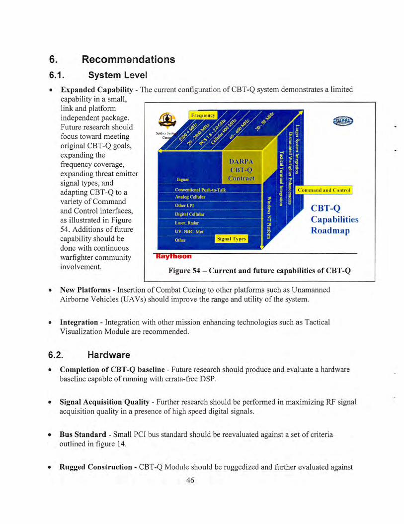
6. Recommendations
6.1. System Level
• Expanded Capability - The current configuration of CBT -Q system demonstrates a limited capability in a small, link and platform independent package. 8 Future research should focus toward meeting original CBT -Q goals, expanding the frequency coverage, expanding threat emitter signal types, and adapting CBT-Q to a variety of Command and Control interfaces, as illustrated in Figure 54. Additions of future capability should be done with continuous warfighter community involvement.
CBT-Q Capabilities Roadmap
Figure 54 -Current and future capabilities of CBT -Q
• New Platforms- Insertion of Combat Cueing to other platforms such as Unamanned Airborne Vehicles (UAVs) should improve the range and utility of the system.
• Integration - Integration with other mission enhancing technologies such as Tactical Visualization Module are recommended.
6.2. Hardware
• Completion of CBT -Q baseline - Future research should produce and evaluate a hardware baseline capable of running with errata-free DSP.
• Signal Acquisition Quality - Further research should be performed in maximizing RF signal acquisition quality in a presence of high speed digital signals.
• Bus Standard - Small PCI bus standard should be reevaluated against a set of criteria outlined in figure 14.
• Rugged Construction - CBT -Q Module should be ruggedized and further evaluated against
46

militarized environment.
• Weight and Size - Further miniaturization and power and weight reduction should be pursued.
• RF Range - Capabilities to cover additional frequency ranges should be considered, such as insertion of Raytheon's Ultra Comm Receiver, shown in Figure 55 .
•
•
Software
Smart Processing - Future research should focus on smart processing algorithms. Smart algorithms maximize the information-to-MIP 1 ratio, or minimize the amount of instructions required in
Figure 55- Raytheon' s Ultracomm Receiver is a good can~idate for
enhancing CBT -Q's RF frequency coverage to 20-2800 MHz
order to acquire necessary information. Key algorithms are RF detection and geolocation. Research of rapid RF search algorithms is critical. One potential method, originally proposed by Combat Cueing, was to quickly search through the RF spectrum for candidate signals, and then follow that up with more precise detection algorithms. This layered, coarse-to-fine method should maximize the DSP asset utilization while preserving a high probability of detection and minimizing the probability of false alarm.
Low Power - By acquiring information efficiently, DSP resources can be placed in standby mode until threat signals emerge. Further research of this type of techniques is required. Desired
%ofMax. Processing
Power
100%
50%
Raytheon
Power Consumption Profile
Search with no detections
Snooze
Search with detections
..... ~~~!"!!.&~ ....
Time
Figure 56 - Power conscious DSP can drastically reduce system power requirements
power profile is illustrated in the Figure 56.
1 MIP stands for millions instructions per second
47

• Analog Signal Exploitation- Techniques for processing modem radio signals, such as Baud Phase Timing utilized in CBT -Q, rely on bauded (digital symbol based) nature of the signals to minimize data transmissions between sensors. Similar high-bandwidth efficiency, feature extraction and timing based algorithms should be researched for processing conventional push-to-talk radios.
• Joint Tactical Radio System (JTRS) Insertion - As the new military radio of the future is developed, CBT -Q algorithms should be migrated into these radio architectures (Figure 57) for "background" processing of situational awareness algorithms. This theme is currently under investigation on DARPA's Spectrum Supremacy Program. CBT-Q's Geolocation algorithm has been reused on this program.
Figure 57- CBT -Q architecture is compatible with JTRS. Therefore, CBT -Q's software algorithms can be migrated to
future tactical radios.
48 This Jocutnent reports research undertaken alllte U.S. Army Soldier and l3iological Chemical Command, Soldiet: S y stet~ts Ccn.ter, ~ttH.l has
b · 11 e·' No NATICK/TR- ')0 ;() 1[) 111 a senes oft epotls een asstg u . . o<. approved for publication.

7. References
[1] "Combat Cueing Operator Interface Conceptual Simulation", Raytheon, November, 1996
[2] "System Requirements Specification for the Combat Cueing System", January, 1997
[3] "Combat Cueing Technical Overview", Raytheon, November, 1996
[4] "Combat Cueing: The 20 Questions", Raytheon, November 1996
[5] "Combat Cueing, System Performance", Raytheon, November, 1996
[6] "Combat Cueing Hardware", Raytheon, November, 1996
[7] "Requirements Specification for the CBT -Q Basestation/Outstation Subsystem'\ Raytheon, March 4, 1997
[8] "Requirements Specification for the CBT -Q User Station Subsystem", May, 1997'', Raytheon, 26 March, 1997
[9] "Hardware Critical Design Review", Raytheon, 18 August, 1997
[10] "Combat Cueing Software: High Level Architecture and Performance", Raytheon, November, 1997"
[11] "System Requirements Specification for the Base Station CBT-Q Module", Raytheon, 2 April, 1997
[12] "Specification for the Combat Cueing Outstation Requirements", Raytheon, April, 1997
[13] "System Requirements Specification for the Combat Cueing User Station'', Raytheon, 15 April, 1997
[ 14] "Combat Cueing Software Critical Design Review'', Raytheon, 18 August, 1997
[15] "Final Report Combat Cueing System User Station", Boeing, July, 1998
[16] "Fort A.P. Hill Test Report for the Combat Cueing System", Raytheon, 18 December, 1997
[17] "RF Network Test Results, CBTQ 23Sep98 Fort A.P. Hill Test", Raytheon, 23 September, 1998
[18] "COMBAT CUEING SYSTEM RF DETECTION FIELD TEST AT FORT A.P, HILL", Raytheon, 10 March, 1999
49
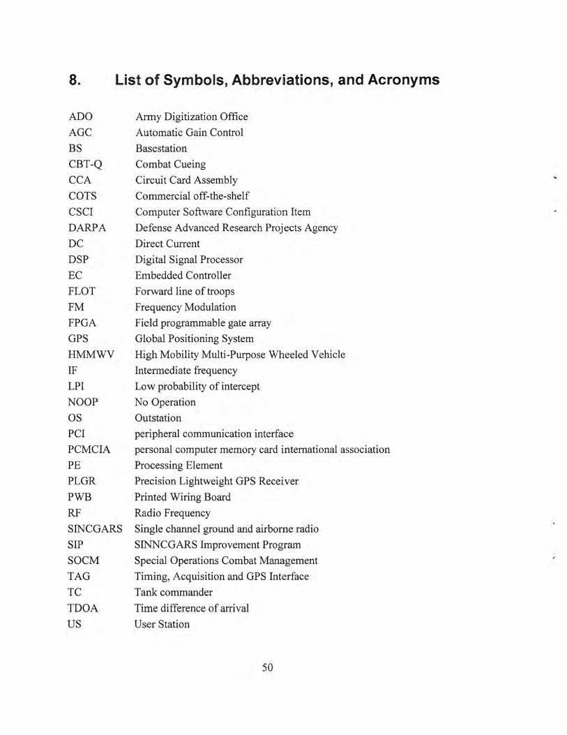
8. List of Symbols, Abbreviations, and Acronyms
ADO Army Digitization Office
AGC Automatic Gain Control
BS Basestation
CBT-Q Combat Cueing
CCA Circuit Card Assembly
COTS Commercial off-the-shelf
CSCI Computer Software Configuration Item
DARPA Defense Advanced Research Projects Agency
DC Direct Current
DSP Digital Signal Processor
EC Embedded Controller
FLOT Forward line of troops
FM Frequency Modulation
FPGA Field programmable gate array
GPS Global Positioning System
HMMWV High Mobility Multi-Purpose Wheeled Vehicle
IF Intermediate frequency
LPI Low probability of intercept
NOOP No Operation
OS Outstation
PCI peripheral communication interface
PCMCIA personal computer memory card international association
PE Processing Element
PLGR Precision Lightweight GPS Receiver
PWB Printed Wiring Board
RF Radio Frequency
SINCGARS Single channel ground and airborne radio
SIP SINNCGARS Improvement Program
SOCM Special Operations Combat Management r.
TAG Timing, Acquisition and GPS Interface
TC Tank commander
TDOA Time difference of arrival
us User Station
50