
Through Hole Design Guidelines · Through Hole Design Guidelines Automation Benefits Board Design...
100
Universal Part Number: GS-354-01 Through Hole Design Guidelines Issued 5/98
Transcript of Through Hole Design Guidelines · Through Hole Design Guidelines Automation Benefits Board Design...

Universal Part Number: GS-354-01
Through Hole Design Guidelines
Issued 5/98

GS-354-01

GS-354-01
Surface MountProduct Line
Surface MountProduct Line
®
Through Hole Design Guidelines
Automation Benefits
Board Design Considerations for Automatic Insertion
Workboard Holder Considerations
Axial Component Insertion
Radial Component Insertion
Dual In-Line Package Insertion
InsertionMachine Division
InsertionMachine Division

GS-354-01

GS-354-01
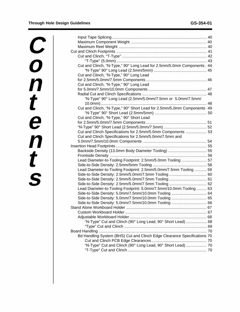
Automation Benefits ................................................................................................ 1
Board Considerations ............................................................................................. 2Size ...................................................................................................................... 2Shape .................................................................................................................. 3Panelization ......................................................................................................... 3Thickness ............................................................................................................. 4Warpage .............................................................................................................. 4Location References ............................................................................................ 5Component Location Objectives .......................................................................... 6
Axis Considerations ....................................................................................... 6
Workboard Holder Considerations ........................................................................ 7Custom Workboard Holders ................................................................................. 7Adjustable Workboard Holders ............................................................................ 8Board Handling System (BHS) Workboard Holders ............................................. 9
Axial Lead Component Insertion .......................................................................... 10Component Input Taping Considerations ........................................................... 11Component Body Length Considerations ........................................................... 12
Minimum Insertion Hole Span Formulas for Various Body Lengths ............ 12Body Diameter Considerations .......................................................................... 13Component Lead Hole Considerations .............................................................. 14Clinch Lengths and Angles ................................................................................ 15Component Density and Lead Diameter Considerations ................................... 16
Topside ........................................................................................................ 16Axial Insertion Tooling Footprint .................................................................. 17Jumper Wire Insertion Tooling Footprint ..................................................... 18Bottomside .................................................................................................. 19
Stand Alone Board Holder ................................................................................. 20Custom Workboard Holder .......................................................................... 20Adjustable Workboard Holder ...................................................................... 20
Board Handling .................................................................................................. 21Single Bd Transfer Bd Holder: Axial Mach (Tbl Positioned at 0° Rotation) . 21Single Bd Transfer Bd Holder: Axial Mach (Tbl Positioned at 90° Rotation) 22
Board Handling System (BHS) .......................................................................... 23Programming Considerations ............................................................................. 24
Optimum Pattern Programming ................................................................... 24
Radial Component Insertion ................................................................................. 25Component Input Specifications ........................................................................ 25
Two-Leaded Components, for 2.5mm/5.0mm Tooling ................................ 26Three-Leaded Components, for 2.5mm/5.0mm Tooling .............................. 28Two-Leaded Components, for 2.5mm/5.0mm/7.5mm and5.0mm/7.5mm/10.0mm Tooling ................................................................... 30Three-Leaded Components for 2.5mm/5.0mm/7.5mm and5.0mm/7.5mm/10.0mm Tooling ................................................................... 32Component Lead Hole Considerations ........................................................ 36Recommended Lead Hole Span (2.5mm/5.0mm Components) .................. 37Recommended Lead Hole Span (2.5mm/5.0mm/7.5mm/10.0mm Comp’ts) 38Radial Lead Taped Component Packaging Specifications .......................... 39Taped Component Removal Pull Testing .................................................... 40
Through Hole Design Guidelines
Contents
GS-354-01
Input Tape Splicing ...................................................................................... 40Maximum Component Weight ..................................................................... 40Maximum Reel Weight ................................................................................ 40
Cut and Clinch Footprints .................................................................................. 41Cut and Clinch, “T-Type” ............................................................................. 42
“T-Type” (5.0mm) .................................................................................. 43Cut and Clinch, “N-Type,” 90° Long Lead for 2.5mm/5.0mm Components . 44
“N-Type” 90° Long Lead (2.5mm/5mm) ................................................ 45Cut and Clinch, “N-Type,” 90° Long Leadfor 2.5mm/5.0mm/7.5mm Components ....................................................... 46Cut and Clinch, “N-Type,” 90° Long Leadfor 5.0mm/7.5mm/10.0mm Components ..................................................... 47Radial Cut and Clinch Specifications ........................................................... 48
“N-Type” 90° Long Lead (2.5mm/5.0mm/7.5mm or 5.0mm/7.5mm/10.0mm) ................................................................................................ 48
Cut and Clinch, “N-Type,” 90° Short Lead for 2.5mm/5.0mm Components 49“N-Type” 90° Short Lead (2.5mm/5mm) ............................................... 50
Cut and Clinch, “N-Type,” 90° Short Leadfor 2.5mm/5.0mm/7.5mm Components ....................................................... 51“N-Type” 90° Short Lead (2.5mm/5.0mm/7.5mm) ....................................... 52Cut and Clinch Specifications for 2.5mm/5.0mm Components ................... 53Cut and Clinch Specifications for 2.5mm/5.0mm/7.5mm and5.0mm/7.5mm/10.0mm Components .......................................................... 54
Insertion Head Footprints ................................................................................... 55Backside Density (13.0mm Body Diameter Tooling) ................................... 55Frontside Density ........................................................................................ 56Lead Diameter-to-Tooling Footprint: 2.5mm/5.0mm Tooling ....................... 57Side-to-Side Density: 2.5mm/5mm Tooling ................................................. 58Lead Diameter-to-Tooling Footprint: 2.5mm/5.0mm/7.5mm Tooling ........... 59Side-to-Side Density: 2.5mm/5.0mm/7.5mm Tooling .................................. 60Side-to-Side Density: 2.5mm/5.0mm/7.5mm Tooling .................................. 61Side-to-Side Density: 2.5mm/5.0mm/7.5mm Tooling .................................. 62Lead Diameter-to-Tooling Footprint: 5.0mm/7.5mm/10.0mm Tooling ......... 63Side-to-Side Density: 5.0mm/7.5mm/10.0mm Tooling ................................ 64Side-to-Side Density: 5.0mm/7.5mm/10.0mm Tooling ................................ 65Side-to-Side Density: 5.0mm/7.5mm/10.0mm Tooling ................................ 66
Stand Alone Workboard Holder ......................................................................... 67Custom Workboard Holder .......................................................................... 67Adjustable Workboard Holder ...................................................................... 68
“N-Type” Cut and Clinch (90° Long Lead, 90° Short Lead) ................... 68“Type” Cut and Clinch ........................................................................... 69
Board Handling .................................................................................................. 70Bd Handling System (BHS) Cut and Clinch Edge Clearance Specifications 70
Cut and Clinch PCB Edge Clearances .................................................. 70“N-Type” Cut and Clinch (90° Long Lead, 90° Short Lead) ................... 70“T-Type” Cut and Clinch ........................................................................ 70
Through Hole Design Guidelines
Contents

GS-354-01
Single Board Transfer Workboard Holder: Radial Machines .............................. 72Pattern Program Considerations ........................................................................ 73
Optimum Pattern Programming ................................................................... 73Insertion Tooling Rotation and Component Polarity ........................................... 74
Dual In-Line Package Insertion ............................................................................. 75Component Input Specifications ........................................................................ 76
Standard DIP IC Modules ............................................................................ 76Side-Brazed DIP IC Modules ....................................................................... 772- and 4-Lead DIP Modules ......................................................................... 78DIP Socket Modules .................................................................................... 79Brickwall DIP Socket Modules ..................................................................... 80Machined Pin DIP Socket Modules ............................................................. 81
Insertion Hole Diameter Considerations ............................................................ 82Component Lead Considerations ....................................................................... 82Clinch Lengths and Angles ................................................................................ 83
Inward Clinch ............................................................................................... 83Outward Clinch ............................................................................................ 83
Density Considerations ...................................................................................... 84DIP or DIP Socket Insertion ........................................................................ 84Brickwall Insertion........................................................................................ 85DIP Tooling to SMT Clearance (Topside) .................................................... 86Socket Tooling to SMT Clearance (Topside) ............................................... 87Clinch Tooling to SMT Clearance (Bottomside) ........................................... 88
Stand Alone Workboard Holder ......................................................................... 89Custom Workboard Holder .......................................................................... 89Adjustable Workboard Holder ...................................................................... 89
Board Handling .................................................................................................. 90Single Board Transfer Workboard Holder: Dual In-Line Packages(Table Positioned at 0° Rotation) ................................................................. 90Single Board Transfer Workboard Holder: Dual In-Line Packages(Table Positioned at 90° Rotation) ............................................................... 91
Programming Considerations ............................................................................. 92Optimum Pattern Programming ................................................................... 92
Through Hole Design Guidelines
Contents

GS-354-01
All specifications are subject to periodic review and may be changed withoutnotice.
© Universal Instruments Corporation, 1998. All rights reserved.
The following are trademarks of Universal Instruments Corporation, registeredU.S. Patent and Trademark Office: Multi-Module, Pass-Thru, Uni-Module,Universal, U-Design logo.

Page 1GS-354-01
Automation Benefits
The purpose of this document is to improve printed circuit boarddesign and layout by detailing the basic considerations associatedwith the electronic assembly process. Universal’s experience hasshown that applying these design principles produces efficient,reliable board designs.
Automatic component insertion provides the consistency required toensure the highest levels of circuit board quality, throughput, andprocess control. When properly planned and implemented, auto-matic component insertion provides significant cost savings in theprinted circuit board assembly process.
The benefits realized from automating circuit board assembly pro-cesses span all areas of manufacturing. Ultimately, all of thesebenefits result in improved products and reduced production costs.
Three key inputs affect the economics and logistics of PC boardassembly: (1) the circuit boards, (2) the equipment used to assemblethe boards, and (3) the components to be inserted. By preciselyunderstanding and standardizing these three primary elements,manufacturers can improve the quality of the finished boards,increase the throughput of the assembly equipment and the system,and more precisely define the process control standards to provide abasis for future applications. Standardizing these elements reducesprocess variability, which leads to increased insertion reliability,improved product quality, enhanced system price/performance and,ultimately, reduced production costs.
Page 2 GS-354-01
69.85 (2.75)
69.85(2.75)
Single Head Inserters Dual Head Inserters (Axial)
Width
Length Length
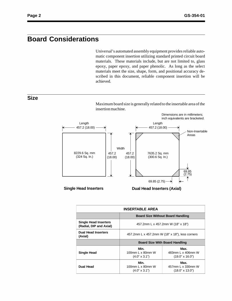
Dimensions are in millimeters;inch equivalents are bracketed.
8229.6 Sq. mm(324 Sq. In.)
7635.2 Sq. mm(300.6 Sq. In.)
457.2(18.00)
457.2(18.00)
Non-InsertableAreas
457.2 (18.00) 457.2 (18.00)
INSERTABLE AREA
Board Size Without Board Handling
Single Head Inserters(Radial, DIP and Axial)
457.2mm L x 457.2mm W (18" x 18")
Dual Head Inserters(Axial)
457.2mm L x 457.2mm W (18" x 18"), less corners
Board Size With Board Handling
Single HeadMin.
100mm L x 80mm W(4.0" x 3.1")
Max.483mm L x 406mm W
(19.0" x 16.0")
Dual HeadMin.
100mm L x 80mm W(4.0" x 3.1")
Max.457mm L x 330mm W
(18.0" x 13.0")
Board Considerations
Universal’s automated assembly equipment provides reliable auto-matic component insertion utilizing standard printed circuit boardmaterials. These materials include, but are not limited to, glassepoxy, paper epoxy, and paper phenolic. As long as the selectmaterials meet the size, shape, form, and positional accuracy de-scribed in this document, reliable component insertion will beachieved.
SizeMaximum board size is generally related to the insertable area of theinsertion machine.

Page 3GS-354-01
Non-symmetrical Symmetrical
Not acceptable for board handling Preferred shape with board handling,utilizing breakaway inserts
Single PrintedCircuit Board 4 Circuit Panel/Array
Shape
For machines operating in a stand-alone configuration, board shape(rectangle and square, for example) is not a major concern as theseboards are typically placed on a dedicated workboard holder.Machines using automatic board handling require special consider-ation to size, shape, warpage, and cutouts.
Panelization
Throughput may be increased by positioning small boards intomultiple breakaway panels/arrays. Standardization of panel sizewill reduce setup time during job changeover.

Page 4 GS-354-01
Thickness
Universal’s insertion machines and board handling equipment canprocess boards with thicknesses of:
Warpage
Warpage should be minimized. Board warpage may cause boardtransfer errors and reduce insertion performance.
A
B
Max. A B
Axial, DIP 3.17mm (0.125") 3.17mm (0.125")
Radial 1.60mm (0.063") 3.17mm (0.125")
Board Thickness
Radial, Axial, DIP0.8mm - 2.36mm(0.032" - 0.093")
BHS Board Handling0.8mm - 2.36mm(0.032" - 0.093")
SBT Board Handling1.52mm - 2.36mm(0.060" - 0.093")

Page 5GS-354-01
Location References
Of prime importance in board design and construction is the estab-lishment of accurate datum points. Datum holes provide the locatingreferences to which all holes are drilled or punched. These referencesare also used to accurately position the board on the workboardholder and reduce printed circuit board tolerance accumulation.
Printed Circuit Board Design Considerations
Notes:1. For recommended insertion hole diameters, see appropriate sections later in this document:
Axial (page 14), Radial (page 36), DIP (page 78).
2. Datum holes should be positioned with the longest lateral span between them.
3. Standardization of datum hole diameters and spacing reduces downtime associated with changeover.
4. These symbols represent geometric tolerancing in accordance with ANSI Y14.5M.
5. When designing boards for PASS-THRU II Board Handling configuration, the maximum locating holediameter is 4.74mm (0.187").
Note 4
SCS M A B0.22mm(0.0085")
D1
E1 E2
Note 1
E3 E4
Note 2D2
-C-
-A-MinimumRecommendedMaximum
3.17 (0.125)6.35 (0.250)7.62 (0.300)
Minimum ØRecommended ØMaximum Ø
3.17 (0.125)3.96 (0.156)6.35 (0.250)
Note 3, 5
-B-
Y Axis
MinimumMaximum
3.17 (0.125)6.35 (0.250)
X Axis
Dimensions are in millimeters;inch equivalents are bracketed.
HOLE DIAMETERTOLERANCE
HOLE POSITION TOLERANCE
E1 - E4 (Insertion Holes) ±0.07mm (0.003")
D1 (Primary Datum Hole)±0.05mm (0.002")
D2 (Secondary Datum Hole)

Page 6 GS-354-01
Component Location Objectives
Axis Considerations
Universal insertion machines are capable of inserting components at0° and 90°. For maximum throughput on DIP and axial inserters,components should be inserted in one axis only. Radial machines caninsert components at 0° or 90° without affecting throughput.
Two axes insertion, as shown below, is an acceptable and efficientway of inserting components.
NotAcceptable
Acceptable
Insertion at other than 0° or 90° is not possible.
Page 7GS-354-01
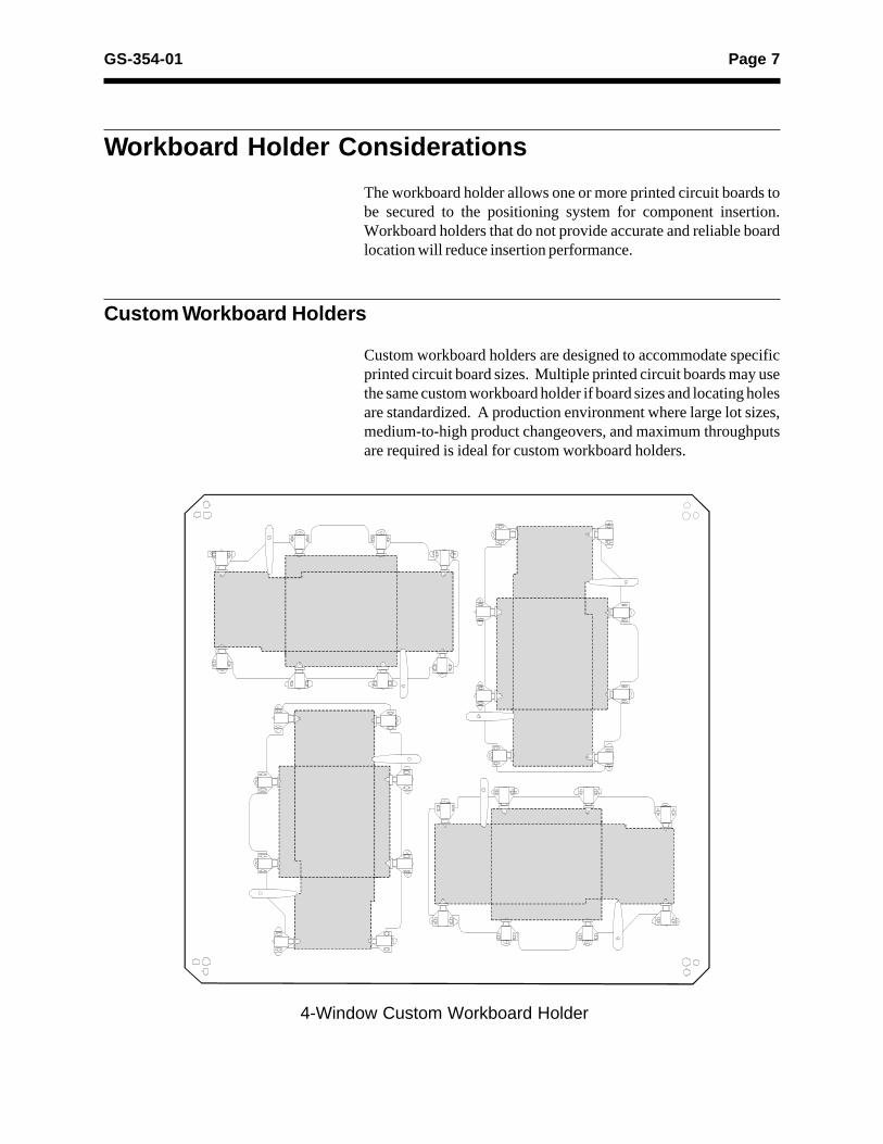
Workboard Holder Considerations
The workboard holder allows one or more printed circuit boards tobe secured to the positioning system for component insertion.Workboard holders that do not provide accurate and reliable boardlocation will reduce insertion performance.
Custom Workboard Holders
Custom workboard holders are designed to accommodate specificprinted circuit board sizes. Multiple printed circuit boards may usethe same custom workboard holder if board sizes and locating holesare standardized. A production environment where large lot sizes,medium-to-high product changeovers, and maximum throughputsare required is ideal for custom workboard holders.
4-Window Custom Workboard Holder
Page 8 GS-354-01
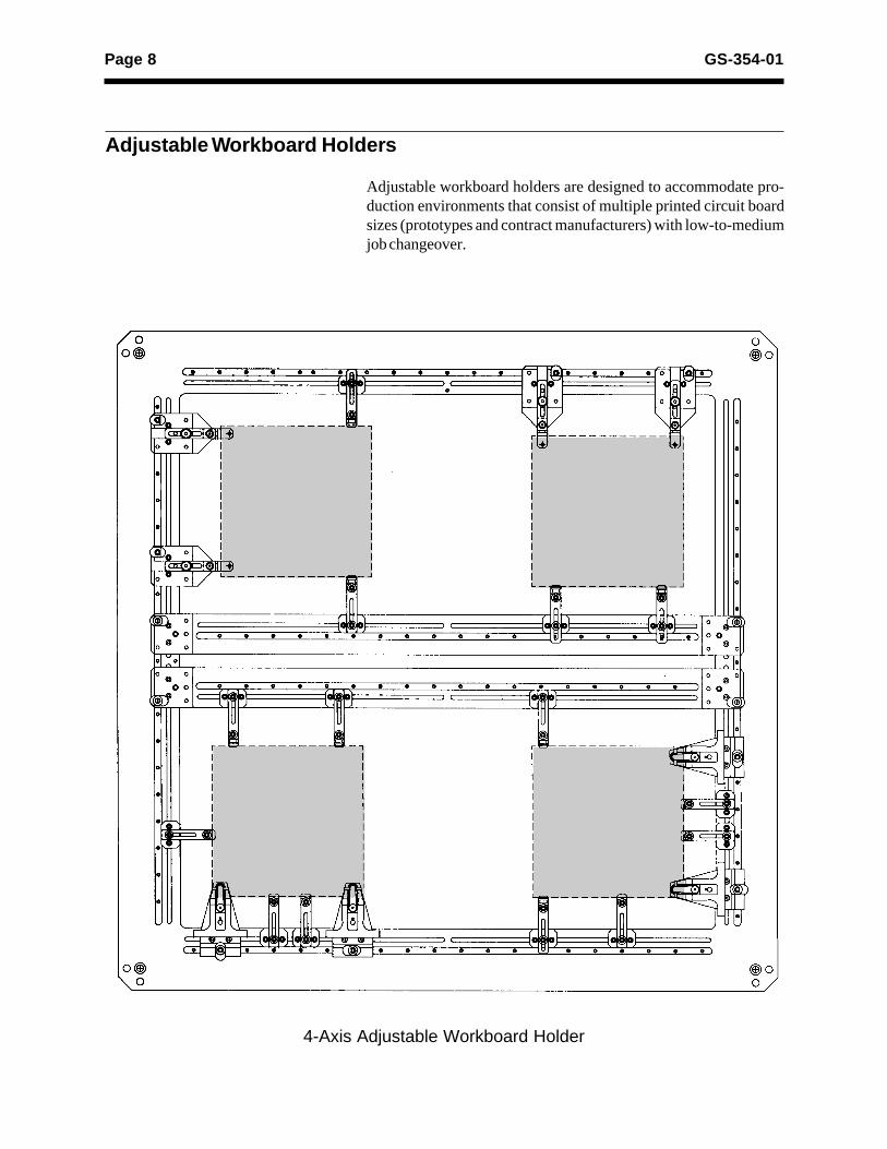
Adjustable Workboard Holders
Adjustable workboard holders are designed to accommodate pro-duction environments that consist of multiple printed circuit boardsizes (prototypes and contract manufacturers) with low-to-mediumjob changeover.
4-Axis Adjustable Workboard Holder
Page 9GS-354-01
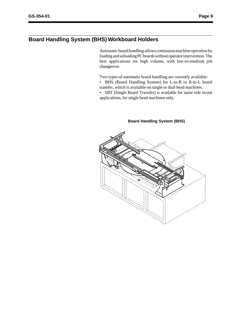
Board Handling System (BHS) Workboard Holders
Automatic board handling allows continuous machine operation byloading and unloading PC boards without operator intervention. Thebest applications are high volume, with low-to-medium jobchangeover.
Two types of automatic board handling are currently available:• BHS (Board Handling System) for L-to-R or R-to-L boardtransfer, which is available on single or dual head machines.• SBT (Single Board Transfer) is available for same side in/outapplications, for single head machines only.
Board Handling System (BHS)
Page 10 GS-354-01
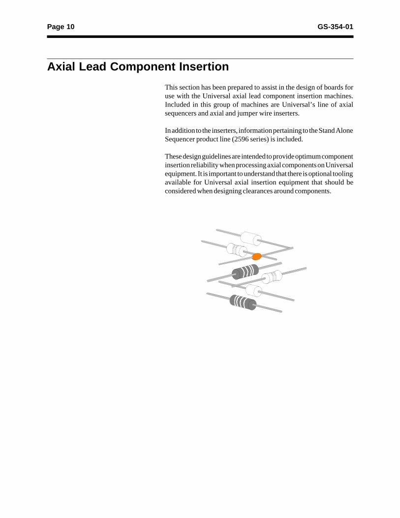
Axial Lead Component Insertion
This section has been prepared to assist in the design of boards foruse with the Universal axial lead component insertion machines.Included in this group of machines are Universal’s line of axialsequencers and axial and jumper wire inserters.
In addition to the inserters, information pertaining to the Stand AloneSequencer product line (2596 series) is included.
These design guidelines are intended to provide optimum componentinsertion reliability when processing axial components on Universalequipment. It is important to understand that there is optional toolingavailable for Universal axial insertion equipment that should beconsidered when designing clearances around components.

Page 11GS-354-01
Component Input Taping Considerations
Notes:1. It is acceptable to use up to two sizes larger (wider) “input class” to the sequencer than recommended.
2. For stand-alone sequencers, Std output is the standard output class. Others must be requested through Universal's “Request ForQuote” process. Sequencer inserters are available with class A output (model 6241D) or with class AAA output (6242E). Othersmust be requested through RFQ process.
SEQUENCERINPUT
2596 Series or6241 Series
STAND-ALONE SEQUENCEROUTPUT
2596 Series
VCD SEQUENCERSEQUENCED OUTPUT
6241 Series
INPUTCLASS
DISTANCEBETWEEN
TAPES
OUTPUTCLASS
DISTANCEBETWEEN
TAPES
MAX. BODYLENGTH
MAX.INSERTION
HOLE CENTERDISTANCE (FORSTAND-ALONE
VCD)
OUTPUTCLASS
COMPONENTCUT LENGTH
MAX. BODYLENGTH
MAX.INSERTION
HOLECENTER
DISTANCE
26mm 26mm (1.024")±1.5mm(0.059")
N/A _ _ _ AAA 26mm(1.024")
7.6mm(0.300")
12.7mm(0.500")
S1 49mm (1.930")±1.5mm(0.059")
AA 36.1mm(1.42")
12.7mm(0.50")
14.8mm(0.58")
AA 45.5mm(1.792")
12.7mm(0.500")
16.5mm(0.650")
I 52.4mm(2.063") ±
1.5mm (0.059")
A 41.1mm(1.62")
15.7mm(0.62")
19.8mm(0.78")
A 50.2mm(1.980")
15.7mm(0.620")
21.6mm(0.850")
I 52.4mm(2.063")
Std 43.7mm(1.72")
15.7mm(0.62")
22.35mm(0.88")
N/A _ _ _
II 63.5mm(2.500")±1.5mm(0.059")
B 52.3mm(2.06")
19.1mm(0.75")
30.99mm(1.22")
N/A _ _ _
III 73mm (2.874")±1.5mm(0.059")
C 60.5mm(2.38")
25.4mm(1.00")
32.26mm(1.27")
N/A _ _ _
Page 12 GS-354-01
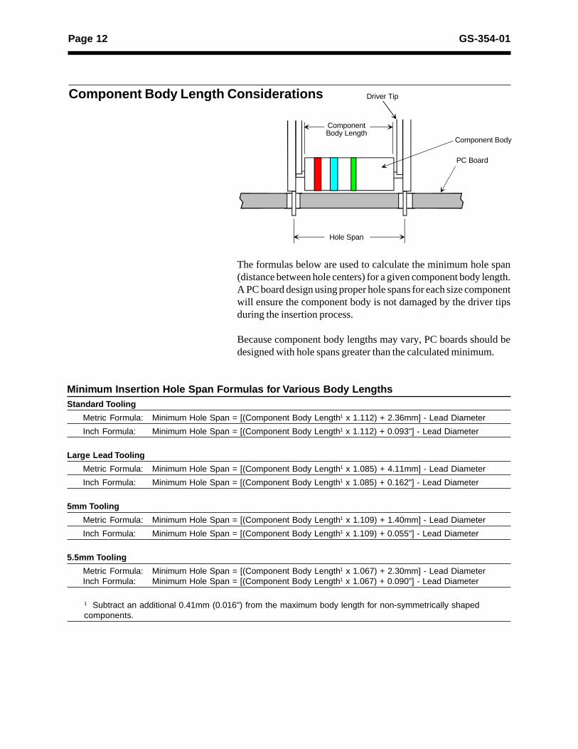
Component Body Length Considerations
The formulas below are used to calculate the minimum hole span(distance between hole centers) for a given component body length.A PC board design using proper hole spans for each size componentwill ensure the component body is not damaged by the driver tipsduring the insertion process.
Because component body lengths may vary, PC boards should bedesigned with hole spans greater than the calculated minimum.
Minimum Insertion Hole Span Formulas for Various Body LengthsStandard Tooling
Metric Formula: Minimum Hole Span = [(Component Body Length1 x 1.112) + 2.36mm] - Lead Diameter
Inch Formula: Minimum Hole Span = [(Component Body Length1 x 1.112) + 0.093"] - Lead Diameter
Large Lead Tooling
Metric Formula: Minimum Hole Span = [(Component Body Length1 x 1.085) + 4.11mm] - Lead Diameter
Inch Formula: Minimum Hole Span = [(Component Body Length1 x 1.085) + 0.162"] - Lead Diameter
5mm Tooling
Metric Formula: Minimum Hole Span = [(Component Body Length1 x 1.109) + 1.40mm] - Lead Diameter
Inch Formula: Minimum Hole Span = [(Component Body Length1 x 1.109) + 0.055"] - Lead Diameter
5.5mm Tooling
Metric Formula: Minimum Hole Span = [(Component Body Length1 x 1.067) + 2.30mm] - Lead DiameterInch Formula: Minimum Hole Span = [(Component Body Length1 x 1.067) + 0.090"] - Lead Diameter
1 Subtract an additional 0.41mm (0.016") from the maximum body length for non-symmetrically shapedcomponents.
Driver Tip
Component Body Length
Hole Span
PC Board
Component Body
Page 13GS-354-01
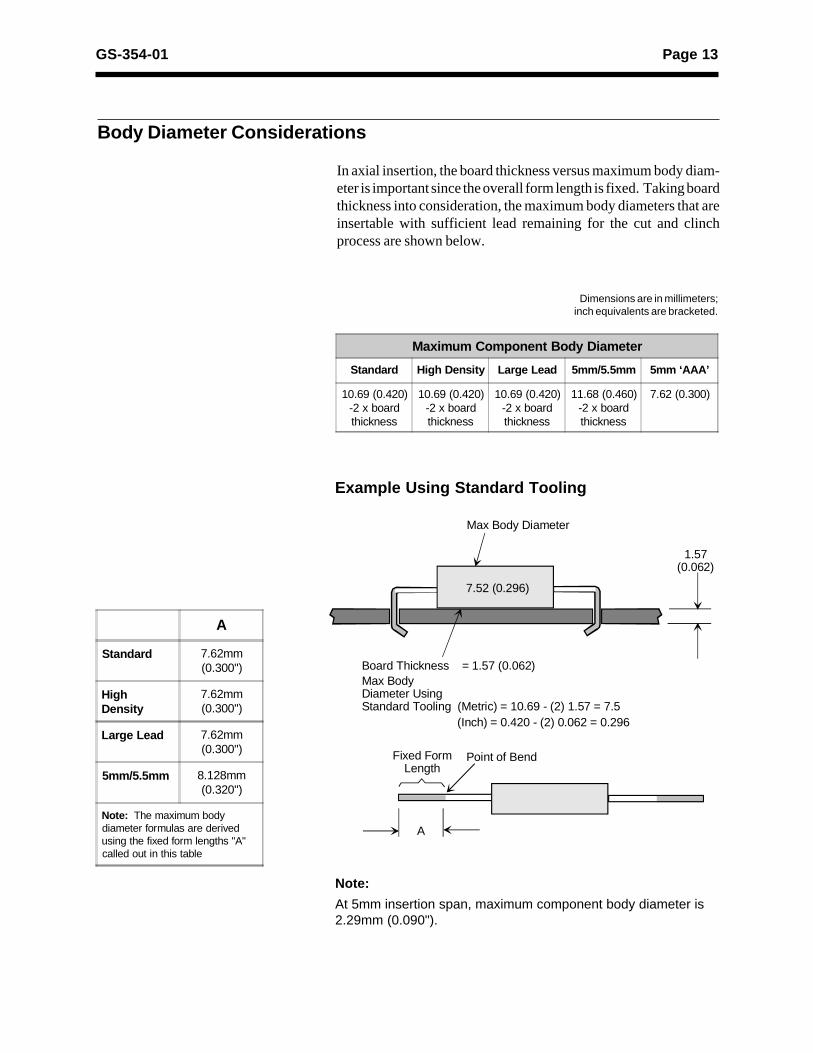
Body Diameter Considerations
In axial insertion, the board thickness versus maximum body diam-eter is important since the overall form length is fixed. Taking boardthickness into consideration, the maximum body diameters that areinsertable with sufficient lead remaining for the cut and clinchprocess are shown below.
Note:
At 5mm insertion span, maximum component body diameter is2.29mm (0.090").
Example Using Standard Tooling
Point of BendFixed FormLength
7.52 (0.296)
1.57(0.062)
Board Thickness = 1.57 (0.062)Max Body Diameter Using Standard Tooling (Metric) = 10.69 - (2) 1.57 = 7.5
A
Max Body Diameter
(Inch) = 0.420 - (2) 0.062 = 0.296
Maximum Component Body Diameter
Standard High Density Large Lead 5mm/5.5mm 5mm ‘AAA’
10.69 (0.420)-2 x boardthickness
10.69 (0.420)-2 x boardthickness
10.69 (0.420)-2 x boardthickness
11.68 (0.460)-2 x boardthickness
7.62 (0.300)
A
Standard 7.62mm(0.300")
HighDensity
7.62mm(0.300")
Large Lead 7.62mm(0.300")
5mm/5.5mm 8.128mm(0.320")
Note: The maximum bodydiameter formulas are derivedusing the fixed form lengths "A"called out in this table
Dimensions are in millimeters;inch equivalents are bracketed.

Page 14 GS-354-01
Component Lead Hole Considerations
Printed circuit boards should be punched or drilled for componentlead insertion to the following recommended hole diameters.
Hole Diameter = Lead Diameter + 0.48mm ±0.08mm.(0.019") (0.003")
Hole sizes less than recommended may result in a degradation ofinsertion reliability, while hole sizes greater than recommended mayresult in loose components in the PC board.

Page 15GS-354-01
Clinch Lengths and Angles
Clinch lead angle is adjustable over a range (0°- 45°). Clinch leadlength is adjustable from 1.28mm (0.050") to 1.80mm (0.071") andis measured from the center of the insertion hole to the end of the lead.
ClinchLength Clinch
Length
Clinch Pattern Options
90° Clinch 45° Clinch
Page 16 GS-354-01
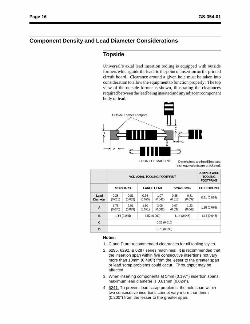
Component Density and Lead Diameter Considerations
Topside
Universal’s axial lead insertion tooling is equipped with outsideformers which guide the leads to the point of insertion on the printedcircuit board. Clearance around a given hole must be taken intoconsideration to allow the equipment to function properly. The topview of the outside former is shown, illustrating the clearancesrequired between the lead being inserted and any adjacent componentbody or lead.
Notes:
1. C and D are recommended clearances for all tooling styles.
2. 6295, 6292, & 6287 series machines: It is recommended thatthe insertion span within five consecutive insertions not varymore than 10mm (0.400") from the lesser to the greater spanor lead scrap problems could occur. Throughput may beaffected.
3. When inserting components at 5mm (0.197") insertion spans,maximum lead diameter is 0.61mm (0.024").
4. 6241: To prevent lead scrap problems, the hole span withintwo consecutive insertions cannot vary more than 5mm(0.200") from the lesser to the greater span.
Dimensions are in millimeters;inch equivalents are bracketed.
VCD AXIAL TOOLING FOOTPRINTJUMPER WIRE
TOOLINGFOOTPRINT
STANDARD LARGE LEAD 5mm/5.5mm CUT TOOLING
LeadDiameter
0.38(0.015)
0.81(0.032)
0.64(0.025)
1.07(0.042)
0.38(0.015)
0.81(0.032)
0.61 (0.024)
A1.78
(0.070)2.01
(0.079)1.80
(0.071)2.08
(0.082)0.97
(0.038)1.22
(0.048)1.98 (0.078)
B 1.14 (0.045) 1.57 (0.062) 1.14 (0.045) 1.14 (0.045)
C 0.25 (0.010)
D 0.76 (0.030)
C
C
A
B
Outside Former Footprint
FRONT OF MACHINE
D

Page 17GS-354-01
Axial Insertion Tooling Footprint
6.25(0.25)
0.48 (0.019)
2.29 (0.090)
2.29 (0.090)
Tooling FootprintStandard Large Lead 5mm/5.5mm
Fron
t Vie
wS
ide
Vie
wB
otto
m V
iew
0.84 (0.033)
3.18 (0.125)
2.36 (0.093)
0.48(0.019)
1.27 (0.050)
2.29 (0.090)
2.29 (0.090)
12.19(0.489)
2.29(0.090)
3.81(0.150)
1.27(0.050)15o
6.35(0.25)
6.35(0.25)
6.25(0.25)
Dimensions are in millimeters;inch equivalents are bracketed.
Page 18 GS-354-01
Dimensions are in millimeters;inch equivalents are bracketed.
FR
ON
T V
IEW
SID
E V
IEW
BO
TT
OM
VIE
W
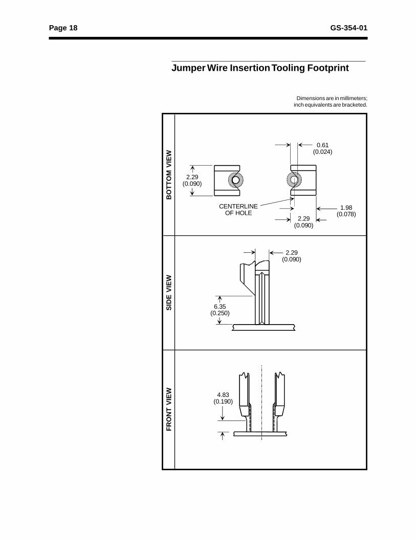
Jumper Wire Insertion Tooling Footprint
2.29(0.090)
CENTERLINE OF HOLE
2.29(0.090)
1.98(0.078)
0.61(0.024)
6.35(0.250)
4.83(0.190)
2.29(0.090)

Page 19GS-354-01
Bottomside
Note:
Clinch anvils are symmetrical about the centerline. Alldimensions are typical for both sides of the anvils.
Dimensions are in millimeters;inch equivalents are bracketed.
Component Height
DistanceFrom C
A
0.51 x 2.72 (0.020 x 0.107)
0.76 x 3.35 (0.030 x 0.132)
1.02 x 3.96 (0.040 x 0.156)1.27 x 4.57 (0.050 x 0.180)
1.52 x 5.21 (0.060 x 0.205)
2.29 x 6.43 (0.090 x 0.253)
3.18 x 7.67 (0.125 x 0.302)
9.25 (0.364)
6.10 (0.240)
2.77 (0.109)
5.97 (0.235)
22°
45°
6.22 (0.245)4.06 (0.160)2.54 (0.100)
6.22 (0.245)4.06 (0.160)2.54 (0.100)
7.32 (0.288) 7.32 (0.288)
3.56 (0.140) 3.56 (0.140)
3.18 x 6.73(0.125 x 0.265)
3.18 x 3.30(0.125 x 0.130)
Fiber OpticContinuity
“A”ANVIL STYLES
Standard 5.0mm
Continuity3.37mm
(0.133")
2.62mm
(0.103")
Fiber Optic3.12mm(0.123")
2.54mm(0.100")
Page 20 GS-354-01
Dimensions are in millimeters;inch equivalents are bracketed.
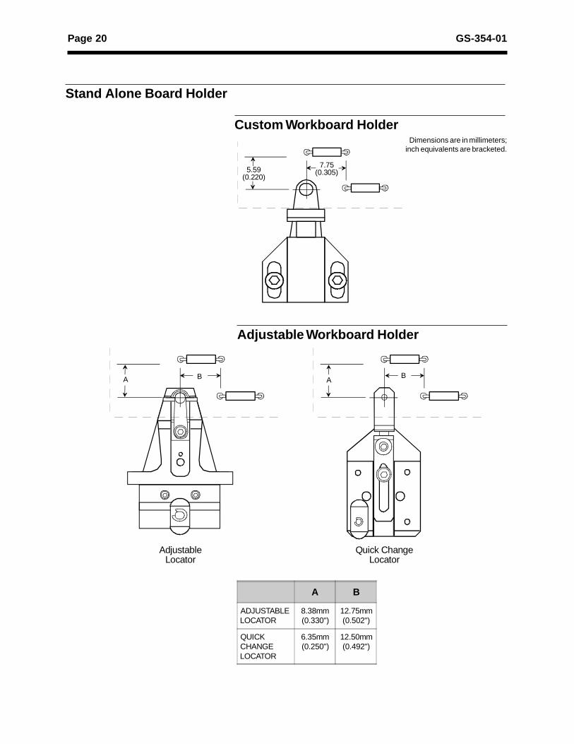
Stand Alone Board Holder
Custom Workboard Holder
Adjustable Workboard Holder
A B
ADJUSTABLELOCATOR
8.38mm(0.330")
12.75mm(0.502")
QUICKCHANGELOCATOR
6.35mm(0.250")
12.50mm(0.492")
5.59(0.220)
7.75(0.305)
A B AB
AdjustableLocator
Quick ChangeLocator
Page 21GS-354-01
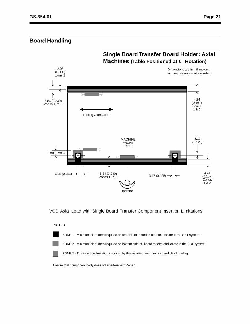
VCD Axial Lead with Single Board Transfer Component Insertion Limitations
Board Handling
Single Board Transfer Board Holder: AxialMachines (Table Positioned at 0° Rotation)
ZONE 1 - Minimum clear area required on top side of board to feed and locate in the SBT system.
ZONE 2 - Minimum clear area required on bottom side of board to feed and locate in the SBT system.
ZONE 3 - The insertion limitation imposed by the insertion head and cut and clinch tooling.
Ensure that component body does not interfere with Zone 1.
NOTES:
Tooling Orientation
MACHINEFRONT
REF.
5.84 (0.230)Zones 1, 2, 3
5.08 (0.200)
6.38 (0.251) 5.84 (0.230)Zones 1, 2, 3 3.17 (0.125)
3.17(0.125)
2.03(0.080)Zone 1
Operator
4.24 (0.167)Zones 1 & 2
Dimensions are in millimeters;inch equivalents are bracketed.
4.24(0.167)Zones1 & 2

Page 22 GS-354-01
VCD Axial Lead with Single Board Transfer Component Insertion Limitations
Single Board Transfer Board Holder: AxialMachines (Table Positioned at 90° Rotation)
ZONE 1 - Minimum clear area required on top side of board to feed and locate in the SBT system.
ZONE 2 - Minimum clear area required on bottom side of board to feed and locate in the SBT system.
ZONE 3 - The insertion limitation imposed by the insertion head and cut and clinch tooling.
Ensure that component body does not interfere with Zone 1.
NOTES:
3.17 (0.125)
4.24 (0.167)Zones 1 & 2
3.17(0.125)
7.24 (0.285)Zones 1, 2, 3
5.08(0.200)
Dimensions are in millimeters;inch equivalents are bracketed.
7.24 (0.285)Zones 1, 2, 3 6.38 (0.251)
Tooling Orientation
MACHINEFRONT
REF.
Operator
4.24 (0.167)Zones 1 & 2
Page 23GS-354-01
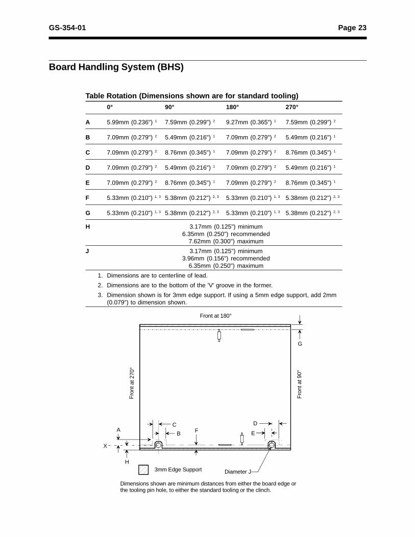
Table Rotation (Dimensions shown are for standard tooling)0° 90° 180° 270°
A 5.99mm (0.236") 1 7.59mm (0.299") 2 9.27mm (0.365") 1 7.59mm (0.299") 2
B 7.09mm (0.279") 2 5.49mm (0.216") 1 7.09mm (0.279") 2 5.49mm (0.216") 1
C 7.09mm (0.279") 2 8.76mm (0.345") 1 7.09mm (0.279") 2 8.76mm (0.345") 1
D 7.09mm (0.279") 2 5.49mm (0.216") 1 7.09mm (0.279") 2 5.49mm (0.216") 1
E 7.09mm (0.279") 2 8.76mm (0.345") 1 7.09mm (0.279") 2 8.76mm (0.345") 1
F 5.33mm (0.210") 1, 3 5.38mm (0.212") 2, 3 5.33mm (0.210") 1, 3 5.38mm (0.212") 2, 3
G 5.33mm (0.210") 1, 3 5.38mm (0.212") 2, 3 5.33mm (0.210") 1, 3 5.38mm (0.212") 2, 3
H 3.17mm (0.125") minimum6.35mm (0.250") recommended
7.62mm (0.300") maximum
J 3.17mm (0.125") minimum3.96mm (0.156") recommended
6.35mm (0.250") maximum
1. Dimensions are to centerline of lead.
2. Dimensions are to the bottom of the 'V' groove in the former.
3. Dimension shown is for 3mm edge support. If using a 5mm edge support, add 2mm(0.079") to dimension shown.
Board Handling System (BHS)
Front at 180°
Fro
nt a
t 270
°
Fro
nt a
t 90°
AB
C D
EF
G
H
Diameter J
X
Dimensions shown are minimum distances from either the board edge or the tooling pin hole, to either the standard tooling or the clinch.
3mm Edge Support

Page 24 GS-354-01
Programming Considerations
Optimum Pattern Programming
The pattern program can make optimum use of the axial leadinsertion equipment by minimizing X-axis movement. Wheneverpossible, programming should proceed in a plus or minus Y directionand minimal hole span changes.
First Insertion
FRONT OF MACHINE

Page 25GS-354-01
Radial Component Insertion
This section is written to assist in the design of boards for use onUniversal’s radial insertion equipment. This group of machinesincludes radial sequencer /inserters.
Universal’s radial sequencer/inserters are designed to automaticallyinsert randomly sequenced radial leaded devices with two and threetaped leads. Some components, such as SIPs, may have up to 10leads.
Component Input Specifications
Components prepped and taped in a radial leaded configuration,which conform to the specifications described in the Input Specifi-cations on the following pages, can be processed by Universal’sradial sequencer/inserters.

Page 26 GS-354-01
Two-Leaded Components,for 2.5mm/5.0mm Tooling
H0
Note 11
Z
Note 10
H1
l
Note 1, 16
F4
)p
W2
W
F3
W1
P2
Note 1, 17
L1
A
F
H
H1W0
Nd
P1
P0
Nd
Component LeadComponent BodyNd3Note 9
Note 9
Note 13
Note 11
H
Notes 1, 18)p
Nd1
Nd2
ND0
Operator
F
ND
ND ND
)hNotes1, 18
t1
t0
t
)h

Page 27GS-354-01
TWO-LEADED COMPONENT SPECIFICATIONS FOR 2.5mm/5.0mm TOOLINGMinimum Maximum
Symbol Item mm inch mm inch NotesA Component Body Height 0.36 0.014 22.99 0.905
ND Component Body Diameter N/A N/A 13.0 0.512 19
ND0 Feed Hole Diameter 3.7 0.146 4.3 0.169
Nd Lead Diameter (Round) 2.5mm 0.36 0.014 0.61 0.024 9, 12
5.0mm 0.36 0.014 0.71 0.028 9, 12Nd1 Lead Size (Rectangular) 2.5mm 0.36 0.014 0.50 0.020 9, 12
5.0mm 0.28 0.011 0.66 0.026 9, 12Nd
2 Lead Size (Rectangular) 2.5mm 0.36 0.014 0.50 0.020 9, 12
5.0mm 0.28 0.011 0.66 0.026 9, 12Nd3 Lead Across Diagonal 2.5mm N/A N/A 0.61 0.024 9, 12
5.0mm N/A N/A 0.71 0.028 9, 12
F Component Lead Span 2.5mm 2.13 0.084 3.15 0.124 1, 5
5.0mm 4.67 0.184 5.69 0.224 1, 5
F1, F2Component Lead Pitch* N/A N/A N/A N/A
F3
Minimum Inner Spacing BetweenLeads
2.5mm 2.1 0.083 N/A N/A 1, 5, 16
5.0mm 4.34 0.171 N/A N/A 1, 5, 16
F4Maximum Outer Spacing 2.5mm N/A N/A 3.53 0.139
5.0mm N/A N/A 6.1 0.239
F5Lead Pitch 2.4 0.096 2.6 0.104
H0Height of Seating Plane 15.5 0.610 22.5 0.886
H Feed Hole to Bottom of Component 15.5 0.610 22.5 0.886 11, 20
H1Component Height 15.85 0.624 38.5 1.51 14
)h Front-to-Rear Deflection 0.0 0.000 1.0 0.039 1, 18
)h1 Lead Deflection * N/A N/A N/A N/A
l Lead Protrusion 0.0 0.000 1.0 0.039
L Lead Length After Component Removal 8.51 0.335 11.2 0.441 3
L1Lead Wire Enclosure 2.49 0.098 18.31 0.721
P0Feed Hole Pitch 12.4 0.488 13.0 0.512 4
P1Lead Location 2.5mm 4.37 0.172 5.79 0.228
5.0mm 3.10 0.122 4.52 0.178 5
P2
Ordinate to Component Center 5.64 0.222 7.06 0.278 5
)p Deflection Left or Right 00 0.000 1.3 0.051 1, 18
t Overall Tape Thickness 0.51 0.020 0.90 0.035 6
t0Carrier Tape Thickness 0.38 0.015 0.69 0.027
t1
Total Taped Package Thickness 0.86 0.034 1.50 0.059 6
W Tape Width 17.5 0.689 19.0 0.748 7
W0Adhesive Tape Width 5.50 0.216 19.0 0.748 7
W1Feed Hole Location 8.5 0.335 9.75 0.384
W2Adhesive Tape Position 0.0 0.000 6.0 0.236 7
Z Standoff Extensions 0.0 0.000 1.0 0.039
* Applies to three-leaded components only.

Page 28 GS-354-01
Three-Leaded Components,for 2.5mm/5.0mm Tooling
H0H
H1
W2
W0 W
W1
A
P0
F1
P2
F
L1
F4 Notes 1, 17
F2
F3Notes 1, 16
Notes 1, 18)p
)p
ND
NdND0
Note A
Note 15
Note 1
26.16 maximum(1.03)
H1
HH0
Note 13 Note A:Taped component leads for SIPs must be on center ofcomponent body within one lead.
Nd
Component LeadComponent Body Nd3Note 9
Note 9
Note 13
Note 11ND
Nd1
Nd2
Operator
F5)h1)h1
ND
)hNotes1, 18
t1
t0
t
)h
Dimensions are in millimeters;inch equivalents are bracketed.

Page 29GS-354-01
THREE-LEADED COMPONENT SPECIFICATIONS FOR 2.5mm/5.0mm TOOLING
Minimum Maximum
Symbol Item mm inch mm inch Notes
A Component Body Height 0.36 0.014 22.99 0.905
ND Component Body Diameter N/A N/A 13.0 0.512 19
ND0 Feed Hole Diameter 3.7 0.146 4.3 0.169
Nd Lead Diameter (Round) 2.5mm N/A N/A N/A N/A 9, 12
5.0mm 0.36 0.014 0.61 0.024 9, 12
Nd1 Lead Size (Rectangular) 2.5mm N/A N/A N/A N/A 9, 12
5.0mm 0.28 0.011 0.50 0.020 9, 12
Nd2 Lead Size (Rectangular) 2.5mm N/A N/A N/A N/A 9, 12
5.0mm 0.28 0.011 0.50 0.20 9, 12
Nd3 Lead Across Diagonal 2.5mm N/A N/A 0.61 0.024 9, 12
5.0mm N/A N/A 0.71 0.028 9, 12
F Component Lead Span 2.5mm 2.13 0.084 3.15 0.124 1, 5
5.0mm 4.67 0.184 5.69 0.224 1, 5
F1, F2Component Lead Pitch 2.4 0.094 2.9 0.114
F3Minimum Inner Spacing Between Leads 2.5mm 2.11 0.083 N/A N/A 1, 5, 16
5.0mm 4.34 0.171 N/A N/A 1, 5, 16
F4Maximum Outer Spacing 2.5mm N/A N/A 3.53 0.139
5.0mm N/A N/A 6.1 0.239
F5Lead Pitch 2.4 0.096 2.6 0.104
H0Height of Seating Plane 15.5 0.610 22.5 0.886
H Feed Hole to Bottom of Component 15.5 0.610 22.5 0.886 11, 20
H1Component Height 15.85 0.624 38.4 1.51 14
)h Front-to-Rear Deflection 0.0 0.000 1.0 0.039 1, 18
)h1 Lead Deflection N/A N/A 0.1 0.004
l Lead Protrusion 0.0 0.000 1.0 0.039
L Lead Length After Component Removal 8.51 0.335 11.2 0.441 3
L1Lead Wire Enclosure 2.49 0.098 18.31 0.721
P0Feed Hole Pitch 12.4 0.488 13.0 0.512 4
P1Lead Location 2.5mm N/A N/A N/A N/A
5.0mm N/A N/A N/A N/A 5
P2Ordinate to Component Center 5.64 0.222 7.06 0.278 5
)p Deflection Left or Right 0.0 0.000 1.3 0.051 1, 18
t Overall Tape Thickness 0.51 0.020 0.89 0.035 6
t0Carrier Tape Thickness 0.38 0.015 0.69 0.027
t1
Total Taped Package Thickness 0.86 0.034 1.50 0.059 6
W Tape Width 17.5 0.689 19.0 0.748 7
W0
Adhesive Tape Width 5.50 0.216 19.0 0.748 7
W1
Feed Hole Location 8.5 0.335 9.75 0.384
W2
Adhesive Tape Position 0.0 0.000 6.0 0.236 7
Z Standoff Extensions 0.0 0.000 1.0 0.039

Page 30 GS-354-01
Two-Leaded Components, for2.5mm/5.0mm/7.5mm and5.0mm/7.5mm/10.0mm Tooling
H0
Note 11
Z
Note 10
H1
)hNotes1, 18
t1
t0
l
Note 1, 16
F4
)p
W2
W
F3
W1
P2
Note 1, 17
L1
A
F
H
H1W0
Nd
P1
P0
t
Nd
Component LeadComponent BodyNd3Note 9
Note 9
Note 13
Note 11
H
Notes 1, 18)p
Nd1
)h
Nd2
ND0
Operator
F
ND
ND ND
P3
Optional Taping for7.5 and 10.0mm Components

Page 31GS-354-01
TWO-LEADED COMPONENT SPECIFICATIONS FOR 2.5mm/5.0mm/7.5mm and 5.0mm/7.5mm/10.0mm TOOLING
Minimum Maximum
Symbol Item mm inch mm inch Notes
A Component Body Height 0.36 0.014 22.99 0.905
ND Component Body Diameter N/A N/A 13.0 0.512 19
ND0 Feed Hole Diameter 3.7 0.146 4.3 0.169
Nd Lead Diameter (Round) 0.36 0.014 0.86 0.034 9, 12
Nd1, Nd2 Lead Size (Rectangular) 0.28 0.011 0.81 0.032 9, 12
Nd3 Lead Across Diagonal 0.38 0.015 0.86 0.034 9,12
F Component Lead Span 2.5mm 2.13 0.084 3.15 0.124 1, 5
5.0mm 4.67 0.184 5.69 0.224 1, 5
7.5mm 7.22 0.284 8.22 0.324 1, 5
10.0mm 9.76 0.384 10.76 0.424 1, 5
F1, F2Component Lead Pitch* N/A N/A N/A N/A
F3Minimum Inner Spacing Between Leads 2.5mm 1.52 0.060 N/A N/A 1, 5, 16
5.0mm 4.06 0.160 N/A N/A 1, 5, 16
7.5mm 6.71 0.264 N/A N/A 1, 5, 16
10.0mm 9.25 0.364 N/A N/A 1, 5, 16
F4Maximum Outer Spacing 2.5mm N/A N/A 3.81 0.150 1, 5
5.0mm N/A N/A 6.35 0.250 1, 5
7.5mm N/A N/A 8.84 0.348 1, 5
10.0mm N/A N/A 11.38 0.448 1, 5
F5Lead Pitch 2.4 0.096 2.6 0.104
H0Height of Seating Plane 15.5 0.610 22.5 0.886
H Feed Hole to Bottom of Component 15.5 0.610 22.5 0.886 11, 20
H1Component Height 15.85 0.624 38.5 1.51 14
)h Front-to-Rear Deflection 0.0 0.000 1.0 0.039 1, 18
)h1 Lead Deflection N/A N/A 0.1 0.004
l Lead Protrusion 0.0 0.000 1.0 0.039
L Lead Length After Component Removal 8.51 0.335 11.2 0.441 3
L1Lead Wire Enclosure 2.49 0.098 18.31 0.721
P0Feed Hole Pitch 12.4 0.488 13.0 0.512 4
P1Lead Location 2.5mm 4.37 0.172 5.79 0.228 5, 18
5.0mm 3.10 0.122 4.52 0.178 5, 18
7.5mm 1.84 0.072 3.24 0.128 5, 18
10.0mm 0.56 0.022 1.98 0.078 5, 18
P2Ordinate to Component Center 5.64 0.222 7.06 0.278 5
P3Alternate Lead Location 7.5mm 8.19 0.322 9.59 0.378 5, 17, 18
10.0mm 6.92 0.272 8.32 0.328 5, 17, 18
)p Deflection Left or Right 0.0 0.000 1.3 0.051 1, 18
t Overall Tape Thickness 0.51 0.020 0.90 0.035 6
t 0Carrier Tape Thickness 0.38 0.015 0.69 0.027
t 1Total Taped Package Thickness 0.86 0.034 1.50 0.059 6
W Tape Width 17.5 0.689 19.0 0.748 7
W0Adhesive Tape Width 5.50 0.216 19.0 0.748 7
W1Feed Hole Location 8.5 0.335 9.75 0.384
W2Adhesive Tape Position 0.0 0.000 6.0 0.236 7
Z Standoff Extensions 0.0 0.000 1.0 0.039
* Applies to three-leaded components only.
Page 32 GS-354-01
Three-Leaded Components for2.5mm/5.0mm/7.5mm and5.0mm/7.5mm/10.0mm Tooling
H0H
H1
W2
W0 W
W1
A
P0
F1
P2
F
L1
F4 Notes 1, 17
F2
F3Notes 1, 16
Notes 1, 18 Dimensions are in millimeters;inch equivalents are bracketed.
)p
)p
ND
NdND0
Note A
Note 15
Note 1
26.16 maximum(1.03)
H1
HH0
Note 13
Note A:Taped component leads for SIPs must be on center ofcomponent body within one lead.
Nd
Component LeadComponent Body Nd3Note 9
Note 9
Note 13
Note 11ND
Nd1
Nd2
Operator
F5)h1)h1
ND
)hNotes1, 18
t1
t0
t
)h
P1

Page 33GS-354-01
THREE-LEADED COMPONENT SPECIFICATIONS FOR 2.5mm/5.0mm/7.5mm and 5.0mm/7.5mm/10.0mm TOOLIN G
Minimum Maximum
Symbol Item mm inch mm inch Notes
A Component Body Height 0.36 0.014 22.99 0.905
ND Component Body Diameter N/A N/A 13.0 0.512 19
ND0 Feed Hole Diameter 3.7 0.146 4.3 0.169
Nd Lead Diameter (Round) 0.36 0.014 0.86 0.034 9, 12
Nd1, Nd2 Lead Size (Rectangular) 0.28 0.011 0.81 0.032 9, 12
Nd3 Lead Across Diagonal N/A N/A 0.86 0.034 9, 12
F Component Lead Span 2.5mm 2.13 0.084 3.15 0.124 1, 5
5.0mm 4.67 0.184 5.69 0.224 1, 5
F1, F2Component Lead Pitch 2.4 0.094 2.9 0.114 1, 5
F3Minimum Inner Spacing Between Leads 2.5mm 1.52 0.060 N/A N/A 1, 5, 16
5.0mm 4.06 0.160 N/A N/A 1, 5, 16
F4Maximum Outer Spacing 2.5mm N/A N/A 3.81 0.150
5.0mm N/A N/A 6.35 0.250
F5Lead Pitch 2.4 0.096 2.6 0.104
H0Height of Seating Plane 15.5 0.610 22.5 0.886
H Feed Hole to Bottom of Component 15.5 0.610 22.5 0.886 11, 20
H1Component Height 15.85 0.624 38.4 1.51 14
)h Front-to-Rear Deflection 0.0 0.000 1.0 0.039 1, 18
)h1 Lead Deflection N/A N/A 0.1 0.004
l Lead Protrusion 0.0 0.000 1.0 0.039
L Lead Length After Component Removal 8.51 0.335 11.2 0.441 3
L1Lead Wire Enclosure 2.49 0.098 18.31 0.721
P0Feed Hole Pitch 12.4 0.488 13.0 0.512 4
P1Lead Location 3.11 0.122 4.51 0.178 5
P2Ordinate to Component Center 5.64 0.222 7.06 0.278 5
P3 Alternate Lead Location * N/A N/A N/A N/A
)p Deflection Left or Right 0.0 0.000 1.3 0.051 1, 18
t Overall Tape Thickness 0.51 0.020 0.89 0.035 6
t0Carrier Tape Thickness 0.38 0.015 0.69 0.027
t1Total Taped Package Thickness 0.86 0.034 1.50 0.059 6
W Tape Width 17.5 0.689 19.0 0.748 7
W0Adhesive Tape Width 5.50 0.216 19.0 0.748 7
W1Feed Hole Location 8.5 0.335 9.75 0.384
W2Adhesive Tape Position 0.0 0.000 6.0 0.236 7
Z Standoff Extensions 0.0 0.000 1.0 0.039
* Applies to two-leaded components only.

Page 34 GS-354-01
1. Maximum alignment deviation or parallelism between leads shall not be greater than 0.2mm (0.008").This dimension also applies to the component leads after the cardboard has been removed and toall untaped leads.
2. The distance between the tape feed hole and the bottom of the component, and the distance betweenthe tape feed hole and the leads standoff form, shall be equal within 1.0mm (0.039").
3. W hen defective components are clipped from the carrier tape, the remaining protrusion of the leadsshall not exceed W
1 + 1.0mm (W
1 + 0.039").
4. Maximum cumulative variation between tape feed holes shall not exceed + 0.5mm (+ 0.020") overfour pitches.
5. P1 and F are measured at the lead egress from the carrier tape on the component side (P
1 shall not
deviate more than ± 0.13mm (0.005") on the same component reel). P2 is measured at the seating
plane.
6. Overall tape package thickness (t1), including component leads and tape splices, shall not exceed1.5mm (0.059").
7. Hold-down tape not to extend beyond the edge(s) of the carrier tape and there shall not be exposureof the adhesive.
8. For components with standoffs, the dimension is measured from the centerline of the feed hole to theinside radius of the form.
9. To determine which dimension to use in designing the PC board, please refer to “Component LeadHole Considerations” section of this GS.
10. Dimension to be 0.38mm (0.015") larger than hole diameter in the board.
11. If leads are off center of component body, effective ND dimension = 2x distance from center line ofcomponent leads to furthermost edge of component body.
12. Steel leads may not exceed 0.64mm (0.025") in diameter when using an N-type cutter head for2.5mm/5.0mm tooling. For 2.5mm/5.0mm/7.5mm tooling, running steel leads with 0.81mm (0.032")will decrease tooling life. (See Note 9)
13. Parts longer than 12.39mm (0.488"), for example, SIP type components, must be taped 25.4mm (1")on center. Parts taped in this manner result in an increase in transfer time from dispenser head tocarrier clip. Consult your Universal Sales Engineer for 15mm (0.59") or 30mm (1.18") pitch.
14. The distance between the bottom of the guide jaw to bottom of the pusher tip when in full up positionis 30.73mm (1.210"). Full downward travel of the insertion pusher extends to surface of printed circuitboard or top of component, whichever is greater.
15. Dimension applies to untaped leads.
16. F3 dimension is designed to limit the minimum lead span of taped components.
17. F4 dimension is designed to limit the maximum lead span of the taped component.
18. Component deflection ()h, )p) is measured from the centerline of the component at the center topof the component.
19. ND max is 13.0mm.
Notes:

Page 35GS-354-01
Notes: (continued)
20. Minimum H dimension increases with body diameter. See below. Maximum H dimension is notaffected.
Tooling Style ND RectangleNote 11
ND Round H Min
10.5mm mm inch mm inch mm inch
4.57 0.180 5.46 0.215 15.49 0.610
4.90 0.193 6.00 0.236 15.88 0.625
6.20 0.244 8.00 0.315 16.87 0.664
8.26 0.325 10.50 0.413 18.44 0.726
13.0mm
6.15 0.242 6.15 0.242 15.49 0.610
7.00 0.276 7.00 0.276 15.98 0.629
10.00 0.394 10.00 0.394 17.50 0.689
13.00 0.512 13.00 0.512 19.03 0.749

Page 36 GS-354-01
Unguided LeadHoles
TypicalPotentiometer
Typical SIP
Unguided leads require larger hole-to-leadrelationships.
Component Lead Hole Considerations
PC boards should be punched or drilled for component lead insertionto the following recommended hole diameters.
• Hole Diameter = Maximum Lead Diameter + 0.48mm (0.019")±0.08mm (0.003")
Hole sizes less than the recommended size may result in a degrada-tion of insertion reliability, while holes that are greater than recom-mended may result in loose components in the printed circuit board.
Unguided leads require larger hole-to-lead relationships. For trian-gular or in-line layout (such as potentiometers and SIPs), PC boardsshould be punched for the unguided lead(s) to the following recom-mended hole diameter.
• Hole Diameter = Maximum Lead Diameter + 0.58mm (0.023")±0.08mm (0.003")
Note:
For maximum lead diameter, use Nd, Nd1, Nd2, or Nd3, whichever islargest.
For further considerations and examples of lead-to-hole relation-ships, see Pages 41 - 54 for the particular cut and clinch you areinterested in.
Page 37GS-354-01
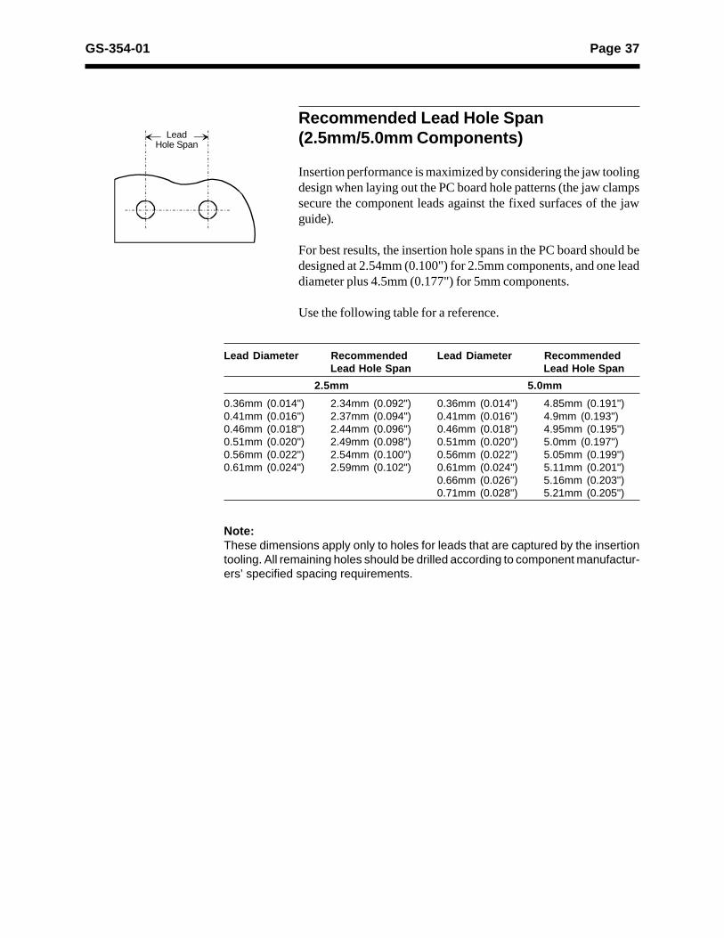
Note:These dimensions apply only to holes for leads that are captured by the insertiontooling. All remaining holes should be drilled according to component manufactur-ers’ specified spacing requirements.
Recommended Lead Hole Span(2.5mm/5.0mm Components)
Insertion performance is maximized by considering the jaw toolingdesign when laying out the PC board hole patterns (the jaw clampssecure the component leads against the fixed surfaces of the jawguide).
For best results, the insertion hole spans in the PC board should bedesigned at 2.54mm (0.100") for 2.5mm components, and one leaddiameter plus 4.5mm (0.177") for 5mm components.
Use the following table for a reference.
Lead Hole Span
Lead Diameter Recommended Lead Diameter RecommendedLead Hole Span Lead Hole Span
2.5mm 5.0mm
0.36mm (0.014") 2.34mm (0.092") 0.36mm (0.014") 4.85mm (0.191")0.41mm (0.016") 2.37mm (0.094") 0.41mm (0.016") 4.9mm (0.193")0.46mm (0.018") 2.44mm (0.096") 0.46mm (0.018") 4.95mm (0.195")0.51mm (0.020") 2.49mm (0.098") 0.51mm (0.020") 5.0mm (0.197")0.56mm (0.022") 2.54mm (0.100") 0.56mm (0.022") 5.05mm (0.199")0.61mm (0.024") 2.59mm (0.102") 0.61mm (0.024") 5.11mm (0.201")
0.66mm (0.026") 5.16mm (0.203")0.71mm (0.028") 5.21mm (0.205")

Page 38 GS-354-01
NOTE
Lead Hole Span
Note:These dimensions apply only to holes for leads that are captured by the insertiontooling. All remaining holes should be drilled according to component manufactur-ers’ specified spacing requirements.
Recommended Lead Hole Span (2.5mm/5.0mm/7.5mm/10.0mm Components)
Insertion performance is maximized by considering the jaw toolingdesign when laying out the PC board hole patterns (the jaw clampssecure the component leads against the fixed surfaces of the jawguide).
For best results, the insertion hole spans in the PC board should bedesigned as follows:• 2.54mm (0.100") for 2.5mm components• one lead diameter + 4.5mm (0.177") for 5.0mm components• one lead diameter + 7.04mm (0.277") for 7.5mm components• one lead diameter + 9.58mm (0.377") for 10.0mm components
Use the following table for a reference.
Lead Diameter Recommended Lead Diameter RecommendedLead Hole Span Lead Hole Span
2.5mm 5.0mm
0.36mm (0.014") 2.54mm (0.100") 0.36mm (0.014") 4.85mm (0.191")0.41mm (0.016") 2.54mm (0.100") 0.41mm (0.016") 4.90mm (0.193")0.46mm (0.018") 2.54mm (0.100") 0.46mm (0.018") 4.95mm (0.195")0.51mm (0.020") 2.54mm (0.100") 0.51mm (0.020") 5.00mm (0.197")0.56mm (0.022") 2.54mm (0.100") 0.56mm (0.022") 5.05mm (0.199")0.61mm (0.024") 2.54mm (0.100") 0.61mm (0.024") 5.11mm (0.201")0.66mm (0.026") 2.54mm (0.100") 0.66mm (0.026") 5.16mm (0.203")0.71mm (0.028") 2.54mm (0.100") 0.71mm (0.028") 5.21mm (0.205")0.76mm (0.030") 2.54mm (0.100") 0.76mm (0.030") 5.26mm (0.207")0.81mm (0.032") 2.54mm (0.100") 0.81mm (0.032") 5.31mm (0.209")0.86mm (0.034") 2.54mm (0.100") 0.86mm (0.034") 5.36mm (0.211")
7.5mm 10.0mm
0.36mm (0.014") 7.39mm (0.291") 0.36mm (0.014") 9.93mm (0.391")0.41mm (0.016") 7.44mm (0.293") 0.41mm (0.016") 9.98mm (0.393")0.46mm (0.018") 7.49mm (0.295") 0.46mm (0.018") 10.03mm (0.395")0.51mm (0.020") 7.54mm (0.297") 0.51mm (0.020") 10.08mm (0.397")0.56mm (0.022") 7.59mm (0.299") 0.56mm (0.022") 10.13mm (0.399")0.61mm (0.024") 7.65mm (0.301") 0.61mm (0.024") 10.18mm (0.401")0.66mm (0.026") 7.70mm (0.303") 0.66mm (0.026") 10.23mm (0.403")0.71mm (0.028") 7.75mm (0.305") 0.71mm (0.028") 10.29mm (0.405")0.76mm (0.030") 7.80mm (0.307") 0.76mm (0.030") 10.34mm (0.407")0.81mm (0.032") 7.85mm (0.309") 0.81mm (0.032") 10.39mm (0.409")0.86mm (0.034") 7.90mm (0.311") 0.86mm (0.034") 10.44mm (0.411")

Page 39GS-354-01
T1
Radial Lead Taped Component PackagingSpecifications
Applicable to reel, cassette, and ammo-pack (fold-pack) containersfor radial lead taped components. A tape trailer having at least 3 feedholes is required at the end of the tape to feed the last component intothe dispensing head.
Notes:1. No more than 3 consecutive missing components are permitted.
2. Polarized components will be oriented in one direction on the inputreel, cassette, or ammo-pack container.
Markings
D3
D1
D2
T2
T
D
Optionaldesign
SPECIFICATIONSYMBOL ITEM MINIMUM MAXIMUM
MM INCH MM INCH
D Reel Diameter 76.2 3.0 360 14.0 D1 Core Diameter 34.9 1.4 102 4.0 D2 Hub Recess Inside Diameter 28.6 1.12 86 3.4 D3 Arbor Hole Diameter 13.8 0.54 38.1 1.5 T Overall Reel Thickness - - 57.2 2.5 T1 Inside Reel Flange Thickness 30 1.2 50 2.0 T2 Hub Recess Depth 9.5 0.374 - -

Page 40 GS-354-01
Taped Component Removal Pull Testing
The taped components shall unwind (reel and cassette) or unfold(ammo-pack) with a force not to exceed 5 Newtons (17.6 oz.). Pulltest shall be applied as illustrated.
Input Tape Splicing
Component may be spliced with an acceptable splicing tape. Univer-sal splicing tape is recommended.
Splices must not interfere with tape feed holes and overall tapethickness may not exceed 1.5mm (0.059").
Maximum Component Weight
The Radial 8 inserts components weighing up to 5 grams. Mass andthe center of gravity affect these limitations. A short 5 gramcomponent with a center of gravity 20.32mm (0.80") above the feedhole may run, but a tall 5 gram component with a center of gravity35.56mm (1.40") above the feed hole may move up or down in thechain clip, affecting reliability.
Maximum Reel Weight
To handle reels of components in excess of 1.8 kg (4 lbs.), consultthe factory.
Ammo-Pack
5N (17.6 oz.)Pull Force
5N (17.6 oz.)Pull ForceCassette
Reel

Page 41GS-354-01
Cut and Clinch Footprints
The cut and clinch cuts the component leads after they are insertedthrough the PC board and then clinches them against the undersideof the PC board, securing the component in place.
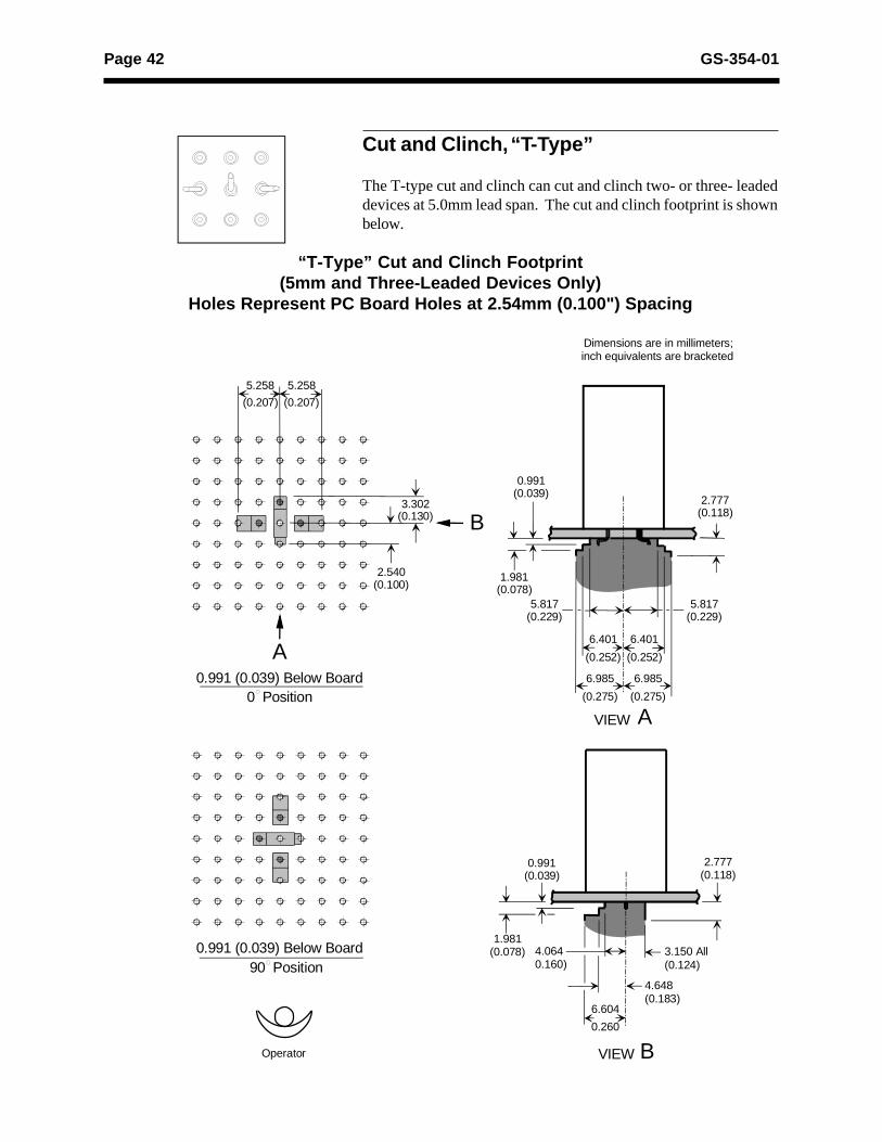
Page 42 GS-354-01
4.0640.160)
6.604
0.260
5.817(0.229)
2.777(0.118)
2.540(0.100)
0.991(0.039)
6.401
(0.252)
6.985
(0.275)
4.648(0.183)
VIEW
VIEW
5.258
(0.207)
3.302(0.130)
1.981(0.078)
0.991 (0.039) Below Board0 Position
A
B
A
B
90 Position3.150 All(0.124)
5.817(0.229)
5.258
(0.207)
6.401
(0.252)
6.985
(0.275)
0.991(0.039)
2.777(0.118)
0.991 (0.039) Below Board
Dimensions are in millimeters;inch equivalents are bracketed
Operator
1.981(0.078)
Cut and Clinch, “T-Type”
The T-type cut and clinch can cut and clinch two- or three- leadeddevices at 5.0mm lead span. The cut and clinch footprint is shownbelow.
“T-Type” Cut and Clinch Footprint(5mm and Three-Leaded Devices Only)
Holes Represent PC Board Holes at 2.54mm (0.100") Spacing

Page 43GS-354-01
Note:Specifications for this cut and clinch (lead angles, lengths, and heights)vary based on PC board hole diameters, component lead diameters,component lead material composition, and component lead shape (round,square, and flat).
“T-Type” (5.0mm)
Front of Machine
Front of Machine
“T-Type” (5.0mm) Tooling Pattern as Viewed from Underside of PC Board
See Note 1
5.0mm, 3-Lead
5.0mm, 2-Lead
Cutter Hd0° position
Cutter Hd90° position
Cutter Hd0° position
Cutter Hd90° position
Notes:1. Dimensions shown reflect factory setup
dimensions and will vary with leaddiameter, materials, hole diameter,spacing, and specific setup requirements.
2. Refer to specific machine dimensions. (PCboard warpage, board and anvil clearance,lead material, and variations of hole orlead diameters cause variations in leadangle, form, and length dimensions.) Cutand clinch tooling parameters shown areexamples for reference only.
3. Parameters based on theoretical values.4. Dimensions shown apply only to the center
lead.5. Lead angles are measured from the
vertical position.
52° ±33°AdjustableAdjustable from
1.40 to 2.41(0.055 to 0.095)
0.46(0.018)1.52 ±0.64
(0.060 ±0.025)
End Lead
Cutter Hd0° position
25° ±15°
1.78 ±0.25(0.070 ±0.010)
1.14 ±0.38(.045 ±.015)
Middle LeadCut and Clinch Hd. 90° Position
Dimensions are in millimeters;inch equivalents are bracketed.

Page 44 GS-354-01
Cut and Clinch, “N-Type,” 90° Long Lead for2.5mm/5.0mm Components
The N-type cut and clinch can cut and clinch 2-and 3-leadedcomponents (2.5mm/5.0mm, or 5.0mm-only). The cut and clinchfootprint and recommended clearances are shown below.
Footprint and Clearances for “N-Type” 90° Long Lead Cut and ClinchHoles Represent PC Board Holes at 2.54mm (0.100") Spacing
3.099(0.122)
2.413(0.095)
VIEW
VIEW
1.981(0.078)
0° Position
A
B
90° Position Right
90° Position Left
3.099(0.122)
2.413(0.095)
3.099(0.122)
2.413(0.095)
2.777(0.118)
0.991(0.039)
1.981(0.078)
0.991 (0.039) Below Board
7.899(0.311)
0.991(0.039)
2.777(0.118)
0.991 (0.039) Below Board
0.991 (0.039) Below Board
10.897(0.429)
A
B
Dimensions are in millimeters;inch equivalents are bracketed
Operator
1.727 ±0.508(0.068 ±0.020)
1.092 ±0.254(0.043 ±0.010)
10.897(0.429)
7.899(0.311)
2.413(0.095)
81° ±9°
3.099(0.122)
7.899(0.311)
7.899(0.311)
10.897(0.429)
10.897(0.429)

Page 45GS-354-01
Lead Ø - 0.635mm (0.025")Hole Ø - 0.99mm (0.039")
“A” Lead Angle 81°±9°
“B” Lead Length 1.73mm ±0.51mm(0.068"±0.020")
“C” Lead Height 1.09mm ±0.25mm(0.043"±0.010")
Notes:1. Values A, B, and C were obtained with the difference
between hole and lead diameter of 0.36mm (0.014").
2. Specifications for this cut and clinch (lead angles,lengths, and heights) vary based on PC board holediameters, component lead diameters, component leadmaterial composition, and component lead shape (round,square, and flat).
Lead length is also dependent on tooling window open-ings.
A
B
C
“N-Type” 90° Long Lead (2.5mm/5mm)

Page 46 GS-354-01
3.099(0.122)
VIEW
0° Position
B
90° Position Right
90° Position Left
1.981(0.078)
0.991 (0.039) Below Board
0.991(0.039)
2.777(0.118)
0.991 (0.039) Below Board
0.991 (0.039) Below Board
A
Operator
3.099(0.122)
7.899(0.311)
7.899(0.311)
10.897(0.429)
10.897(0.429)
2.769(0.109)
VIEW
1.981(0.078)
A
2.777(0.118)
0.991(0.039)
7.899(0.311)
10.897(0.429)
B
Dimensions are in millimeters;inch equivalents are bracketed
1.727 ±0.508(0.068 ±0.020)
1.092 ±0.254(0.043 ±0.010)
10.897(0.429)
7.899(0.311)
4.953(0.195)
81° ±9°
3.099(0.122)
4.953(0.195)
3.099(0.122)
2.769(0.109)
Cut and Clinch, “N-Type,” 90° Long Leadfor 2.5mm/5.0mm/7.5mm Components
The N-type cut and clinch can cut and clinch 2- and 3-leadedcomponents (2.5mm/5.0mm/7.5mm). The cut and clinch footprintand recommended clearances are shown below.
Footprint and Clearances for “N-Type” 90° Long Lead Cut and ClinchHoles Represent PC Board Holes at 2.54mm (0.100") Spacing
Page 47GS-354-01
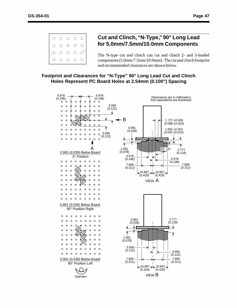
Cut and Clinch, “N-Type,” 90° Long Leadfor 5.0mm/7.5mm/10.0mm Components
The N-type cut and clinch can cut and clinch 2- and 3-leadedcomponents (5.0mm/7.5mm/10.0mm). The cut and clinch footprintand recommended clearances are shown below.
Footprint and Clearances for “N-Type” 90° Long Lead Cut and ClinchHoles Represent PC Board Holes at 2.54mm (0.100") Spacing
3.099(0.122)
4.978(0.196)
VIEW
VIEW
1.981(0.078)
0° Position
A
B
90° Position Right
90° Position Left
3.099(0.122)
3.099(0.122)
4.978(0.196)
2.777(0.118)
0.991(0.039)
1.981(0.078)
0.991 (0.039) Below Board
7.899(0.311)
0.991(0.039)
2.777(0.118)
0.991 (0.039) Below Board
0.991 (0.039) Below Board
10.897(0.429)
A
B
Dimensions are in millimeters;inch equivalents are bracketed
Operator
1.727 ±0.508(0.068 ±0.020)
1.092 ±0.254(0.043 ±0.010)
10.897(0.429)
7.899(0.311)
4.978(0.196)
81° ±9°
3.099(0.122)
7.899(0.311)
7.899(0.311)
10.897(0.429)
10.897(0.429)
4.978(0.196)

Page 48 GS-354-01
A
B
C
Radial Cut and Clinch Specifications
“N-Type” 90° Long Lead (2.5mm/5.0mm/7.5mm or 5.0mm/7.5mm/10.0mm)
Lead Ø - 0.635mm (0.025")Hole Ø - 1.12mm (0.044")
“A” Lead Angle 81° ±9°
“B” Lead Length 1.73mm ±0.51mm(0.068" ±0.020")
“C” Lead Height 1.09mm ±0.25mm(0.043" ±0.010")
Notes:
1. Values A, B, and C were obtained with the differencebetween hole and lead diameter of 0.483mm (0.019").
2. Specifications for this cut and clinch (lead angles, lengths,and heights) vary based on PC board hole diameters,component lead diameters, component lead materialcomposition, and component lead shape (round, square,and flat).
Lead length is also dependent on tooling window openings.

Page 49GS-354-01
4.978(0.196)
2.777(0.118)
7.595(0.299)
VIEW
VIEW
0° Position
A
B
90° Position Left
90° Position Right
3.937(0.155)
4.978(0.196)
A
B
3.937(0.155)
10.592(0.417)
1.981(0.078)
7.595(0.299)
10.592(0.417)
2.777(0.118)
0.991(0.039)
1.981(0.078)
0.991(0.039)
7.595(0.299)
10.592(0.417)
10.592(0.417)
7.595(0.299)
4.978(0.196)
3.937(0.155)
0.991 (0.039) Below Board
0.991 (0.039) Below Board
0.991 (0.039) Below Board
3.937(0.155)
4.978(0.196)
Dimensions are in millimeters;inch equivalents are bracketed
Operator
Cut and Clinch, “N-Type,” 90° Short Lead for2.5mm/5.0mm Components
The N-type cut and clinch can cut and clinch 2-and 3-leadedcomponents (2.5mm/5.0mm, or 5.0mm-only). The cut and clinchfootprint and recommended clearances are shown below.
Footprint and Clearances for “N-Type” 90° Short Lead Cut and ClinchHoles Represent PC Board Holes at 2.54mm (0.100") Spacing

Page 50 GS-354-01
Hole to leaddiameters must bemaintained whenusing this cut andclinch option.
Lead Ø - 0.635mm (0.025")Hole Ø - 0.99mm (0.039")
“A” Lead Angle 81° ±9°
“B” Lead Length 1.52mm ±0.38mm(0.060" ±0.015")
“C” Lead Height 0.76mm ±0.25mm(0.030" ±0.010")
Notes:1. Values A, B, and C were obtained with the difference
between hole and lead diameter of 0.36mm (0.014").
2. Specifications for this cut and clinch (lead angles,lengths, and heights) vary based on PC board holediameters, component lead diameters, component leadmaterial composition, and component lead shape (round,square, and flat).
Lead length is also dependent on tooling window open-ings.
A
B
C
“N-Type” 90° Short Lead (2.5mm/5mm)

Page 51GS-354-01
Cut and Clinch, “N-Type,” 90° Short Leadfor 2.5mm/5.0mm/7.5mm Components
The N-type cut and clinch can cut and clinch 2- and 3-leadedcomponents (2.5mm/5.0mm/7.5mm). The cut and clinch footprintand recommended clearances are shown below.
Footprint and Clearances for “N-Type” 90° Short Lead Cut and ClinchHoles Represent PC Board Holes at 2.54mm (0.100") Spacing
4.978(0.196)
2.777(0.118)
7.595(0.299)
VIEW
VIEW
0° Position
A
B
90° Position Left
90° Position Right
3.937(0.155)
4.978(0.196)
A
B
3.937(0.155)
1.981(0.078)
7.595(0.299)
2.777(0.118)
0.991(0.039)
1.981(0.078)
0.991(0.039)
7.595(0.299)
7.595(0.299)
6.706(0.264)
3.937(0.155)
0.991 (0.039) Below Board
0.991 (0.039) Below Board
0.991 (0.039) Below Board
3.937(0.155)
6.706(0.264)
Dimensions are in millimeters;inch equivalents are bracketed
Operator
10.592(0.417)
10.592(0.417)
10.592(0.417)
10.592(0.417)

Page 52 GS-354-01
Hole to lead diametersmust be maintainedwhen using this cut andclinch option.
A
B
C
“N-Type” 90° Short Lead(2.5mm/5.0mm/7.5mm)
Lead Ø - 0.635mm (0.025")Hole Ø - 1.12mm (0.044")
“A” Lead Angle 81° ±9°
“B” Lead Length 1.52mm ±0.38mm(0.060" ±0.015")
“C” Lead Height 0.76mm ±0.25mm(0.030" ±0.010")
Notes:
1. Values A, B, and C were obtained with the differencebetween hole and lead diameter of 0.483mm (0.19").
2. Specifications for this cut and clinch (lead angles, lengths,and heights) vary based on PC board hole diameters,component lead diameters, component lead materialcomposition, and component lead shape (round, square,and flat).
Lead length is also dependent on tooling window openings.

Page 53GS-354-01
Cut and Clinch Specifications for 2.5mm/5.0mm Components
The cut and clinch tooling matrix that follows is provided as acomparison of current standard Universal cut and clinch tooling.Compared are cut and clinch tooling patterns as viewed from theunderside of the printed circuit board. Parameters are based ontheoretical values.
“N-Type” 90° Long Lead and 90° Short Lead (2.5mm/5.0mm) Tooling Pattern as Viewed from Underside of PC Board
5.0mm, 3-Lead
5.0mm, 2-Lead
Cutter Hd0° position
Cutter Hd90° right position
Front of Machine
Cutter Hd90° left position
Front of Machine
Cutter Hd0° position
Cutter Hd90° right position
Cutter Hd90° left position
Front of Machine
2.5mm, 2-Lead
Cutter Hd0° position
Cutter Hd90° right position
Cutter Hd90° left position
Notes:1. Dimensions shown reflect factory setup dimensions and will vary with lead diameter,
materials, hole diameter, spacing, and specific setup requirements.2. Refer to specific machine dimensions. (PC board warpage, board and anvil
clearance, lead material, and variations of hole or lead diameters cause variations inlead angle, form, and length dimensions.) Cut and clinch tooling parameters shownare examples for reference only.
3. Parameters based on theoretical values.4. Dimensions shown apply only to the center lead.5. Lead angles are measured from the vertical position.

Page 54 GS-354-01
Tooling Pattern as Viewed from Underside of PC Board
“N-Type”90° Long Lead and Short Lead
(2.5mm/5.0mm/7.5mm)
“N-Type”90° Long Lead
(5.0mm/7.5mm/10.0mm)
5.0mm, 3-LeadCutter Hd
90° Left PositionCutter Hd0° Position
Cutter Hd90° Right Position
5.0mm, 2-LeadCutter Hd
90° Left PositionCutter Hd0° Position
Cutter Hd90° Right Position
2.5mm, 2-LeadCutter Hd
90° Left PositionCutter Hd0° Position
Cutter Hd90° Right Position
7.5mm, 2-LeadCutter Hd
90° Left PositionCutter Hd0° Position
Cutter Hd90° Right Position
10mm, 2-LeadCutter Hd
90° Left PositionCutter Hd0° Position
Cutter Hd90° Right Position
7.5mm, 2-LeadCutter Hd
90° Left PositionCutter Hd0° Position
Cutter Hd90° Right Position
5.0mm, 2-LeadCutter Hd
90° Left PositionCutter Hd0° Position
Cutter Hd90° Right Position
Notes:1. Dimensions shown reflect factory setup dimensions and will vary with lead diameter, materials, hole diameter, spacing, and specific setup requirements.2. Refer to specific machine dimensions. (PC board warpage, board and anvil clearance, lead material, and variations of hole or lead diameters cause variations in lead angle, form, and length dimensions.) Cut and clinch tooling parameters shown are examples for reference only.3. Parameters based on theoretical values.4. Dimensions shown apply only to the center lead.5. Lead angles are measured from the vertical position.
Cut and Clinch Specifications for 2.5mm/5.0mm/7.5mm and 5.0mm/7.5mm/10.0mmComponents
The cut and clinch tooling matrix that follows is provided as acomparison of current standard Universal cut and clinch tooling.Compared are cut and clinch tooling patterns as viewed from theunderside of the printed circuit board. Parameters are based ontheoretical values.
Operator

Page 55GS-354-01
Insertion Head Footprints
Backside Density (13.0mm BodyDiameter Tooling)
Dimensions are in millimeters;inch equivalents are bracketed.
Formula: X (Keep Out Area) = Y (Previously Inserted Component Height) + 0.48mm (0.019")
Y
45°
Guide Jaw
Previously InsertedComponent
X
Y
45°
13.00 (0.512) Maximum Component Diameter
Pusher
Note:Reference the cut and clinchappendix for bottom side clearances.
Keep Out Area
View shows component inserted.Tooling ready to return to the home position.
Step 1 Step 2
Page 56 GS-354-01
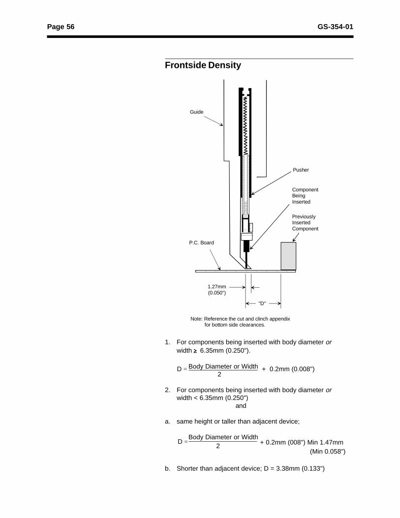
1. For components being inserted with body diameter orwidth $$$$$ 6.35mm (0.250").
Body Diameter or Width + 0.2mm (0.008") 2
2. For components being inserted with body diameter orwidth < 6.35mm (0.250")
and
a. same height or taller than adjacent device;
Body Diameter or Width + 0.2mm (008") Min 1.47mm
(Min 0.058")
b. Shorter than adjacent device; D = 3.38mm (0.133")
D =
2 D =
Frontside Density
Pusher
Guide
Component BeingInserted
Previously InsertedComponent
"D"
1.27mm (0.050")
P.C. Board
Note: Reference the cut and clinch appendix for bottom side clearances.

Page 57GS-354-01
Lead Diameter-to-Tooling Footprint: 2.5mm/5.0mm Tooling
Dimensions are in millimeters;inch equivalents are bracketed
Clamp Clamp
Lead Span2.59 (0.102)0.61 (0.024)
Max. Dia. Leads
1.98 (0.078)
7.54 (0.297)
ClampClamp
Lead Span2.34 (0.092)0.36 (0.014)
Max. Dia. Leads
1.98 (0.078)
7.19 (0.283)
Insertion Tooling
C
Insertion Tooling
CLL
Clamp Clamp
4.5(0.177)
0.36 (0.014)Max. Dia. Leads
Insertion ToolingC
7.24 (0.285)
Clamp Clamp
0.71(0.028)Max. Dia. Leads
Insertion ToolingC
8.1 (0.319)
L
4.5(0.177)
L
Lead Span4.85
(0.191)
Lead Span5.21
(0.205)
Operator
2.5mm
5mm
Note:
View shows minimum and maximum diameter leads clamped,overall dimensions, and lead span relationship to lead diameter.View is top side of the tooling.
Page 58 GS-354-01
Guide Jaw
ClampClamp
Previously InsertedComponent
0.203 (0.008)
"C"
0.203 (0.008)
Previously Inserted
Component
Component Leads
+9.14
(0.360)
Operator
Guide Jaw
Clamp Clamp
Component Leads
4.57(0.180)
0.203 (0.008)
"C"
0.203 (0.008)
Previously InsertedComponent
Previously Inserted
Component +
5.0mm Component Top View
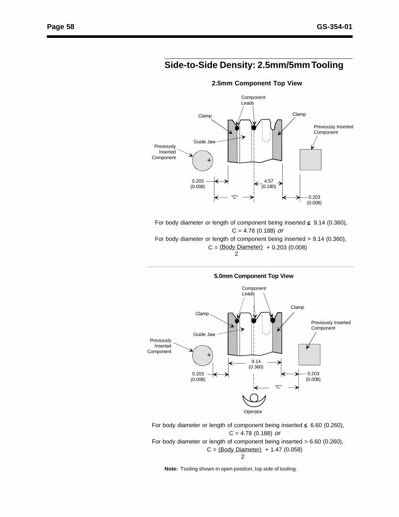
For body diameter or length of component being inserted ##### 6.60 (0.260),C = 4.78 (0.188) or
For body diameter or length of component being inserted > 6.60 (0.260),C = (Body Diameter) + 1.47 (0.058)
2
Note: Tooling shown in open position, top side of tooling.
For body diameter or length of component being inserted ##### 9.14 (0.360),C = 4.78 (0.188) or
For body diameter or length of component being inserted > 9.14 (0.360),
C = (Body Diameter) + 0.203 (0.008)2
2.5mm Component Top View
Side-to-Side Density: 2.5mm/5mm Tooling

Page 59GS-354-01
Lead Diameter-to-Tooling Footprint: 2.5mm/5.0mm/7.5mm Tooling
Note:
View shows minimum and maximum diameter leads clamped, overall dimensions, and lead span relationshipto lead diameter. View is top side of the tooling.
9.85(0.388)
0.36 (0.014)Dia. Leads
2.54 (0.100)
2.54 (0.100)Lead Span
0.81 (0.032)Dia Leads
2.5mm
10.95(0.431)
2.54 (0.100)
2.54 (0.100)Lead Span
Dimensions are in millimeters;inch equivalents are bracketed.
4.50 (0.177)
5.31 (0.209)Lead Span
0.36 (0.014)Dia. Leads
9.82 (0.387)
5.0mm
0.81 (0.032)Dia Leads
10.93 (0.430)
4.50 (0.177)
4.85 (0.191)Lead Span
0.36 (0.014)Dia. Leads
9.85 (0.388)
7.04 (0.277)
7.39 (0.291)
Lead Span
0.81 (0.032)Dia. Leads
10.95 (0.431)
7.04 (0.277)
7.85 (0.309)
Lead Span
7.5mm
Operator
Page 60 GS-354-01
ComponentLeads
ClampGuide Jaw
0.203 (0.008)
ComponentComponent
ClampCL
7.11(0.280)
4.57(0.180)
11.68(0.460)
"D""C"
0.203 (0.008)
Dimensions are in millimeters;inch equivalents are bracketed.
Operator
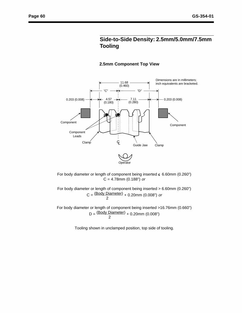
Side-to-Side Density: 2.5mm/5.0mm/7.5mmTooling
For body diameter or length of component being inserted ##### 6.60mm (0.260")C = 4.78mm (0.188") or
For body diameter or length of component being inserted > 6.60mm (0.260")
C = (Body Diameter) + 0.20mm (0.008") or 2
For body diameter or length of component being inserted >16.76mm (0.660")
D = (Body Diameter) + 0.20mm (0.008") 2
Tooling shown in unclamped position, top side of tooling.
2.5mm Component Top View

Page 61GS-354-01
Dimensions are in millimeters;inch equivalents are bracketed.
ClampGuide Jaw
ComponentComponent
Clamp
ComponentLeads
0.203 (0.008)
CL
11.68(0.460)
"D""C"
4.57(0.180)
7.11(0.280)
0.203 (0.008)
Operator
For body diameter or length of component being inserted ##### 9.14mm (0.360")C = 4.78mm (0.188") or
For body diameter or length of component being inserted > 9.14mm (0.360")
C = (Body Diameter) +0.20mm (0.008") or 2
For body diameter or length of component being inserted >14.22mm (0.560")
D = (Body Diameter) + 0.20mm (0.008") 2
Tooling shown in unclamped position, top side of tooling.
5.0mm Component Top View
Side-to-Side Density: 2.5mm/5.0mm/7.5mmTooling
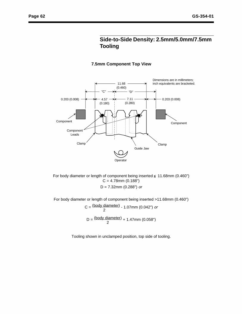
Page 62 GS-354-01
Dimensions are in millimeters;inch equivalents are bracketed.
ComponentLeads
Clamp
Guide Jaw
0.203 (0.008)
ComponentComponent
ClampCL
11.68(0.460)
"D""C"
4.57(0.180)
7.11(0.280)
0.203 (0.008)
Operator
Side-to-Side Density: 2.5mm/5.0mm/7.5mmTooling
For body diameter or length of component being inserted ##### 11.68mm (0.460")C = 4.78mm (0.188")
D = 7.32mm (0.288") or
For body diameter or length of component being inserted >11.68mm (0.460")
C = (body diameter) - 1.07mm (0.042") or 2
D = (body diameter) + 1.47mm (0.058") 2
Tooling shown in unclamped position, top side of tooling.
7.5mm Component Top View

Page 63GS-354-01
Lead Diameter-to-Tooling Footprint: 5.0mm/7.5mm/10.0mm Tooling
Operator
12.29(0.484)
0.36 (0.14)Dia. Leads
4.85 (0.191)Centerlineof Lead Span4.50 (0.177)
Inside Dimension of Leads
13.39(0.527)
0.81 (0.32)Dia. Leads
5.31 (0.209)Centerlineof Lead Span4.50 (0.177)
Inside Dimension of Leads
Dimensions are in millimeters;inch equivalents are bracketed.
5mm
12.29(0.484)
0.36 (0.14)Dia. Leads
7.39 (0.291)Centerlineof Lead Span7.04 (0.277)
Inside Dimension of Leads
13.39(0.527)
0.81 (0.32)Dia. Leads
7.385(0.309)Centerlineof Lead Span7.04 (0.277)
Inside Dimension of Leads
7.5mm
12.29(0.484)
0.36 (0.14)Dia. Leads
9.93 (0.391)Centerlineof Lead Span9.58 (0.377)
Inside Dimension of Leads
13.39(0.527)
0.81 (0.32)Dia. Leads
10.39 (0.409)Centerlineof Lead Span9.58 (0.377)
Inside Dimension of Leads
10mm
Note:View shows minimum and maximum diameter leads clamped, overall dimensions, and lead span relationship to lead diameter. View is top side of tooling.
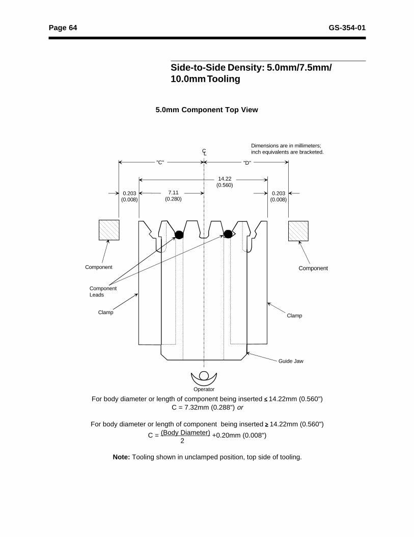
Page 64 GS-354-01
Dimensions are in millimeters;inch equivalents are bracketed.
"D"
Component Leads
"C"
Guide Jaw
ClampClamp
Component Component
0.203(0.008)
7.11(0.280)
14.22(0.560)
CL
0.203(0.008)
Side-to-Side Density: 5.0mm/7.5mm/10.0mm Tooling
For body diameter or length of component being inserted #####14.22mm (0.560")C = 7.32mm (0.288") or
For body diameter or length of component being inserted $$$$$14.22mm (0.560")
C = (Body Diameter) +0.20mm (0.008") 2
Note: Tooling shown in unclamped position, top side of tooling.
Operator
5.0mm Component Top View

Page 65GS-354-01
Side-to-Side Density: 5.0mm/7.5mm/10.0mm Tooling
For body diameter or length of component being inserted #####11.68mm (0.460")C = 7.32mm (0.288") or
For body diameter or length of component being inserted >11.68mm (0.460")
C = (Body Diameter) + 1.47mm (0.058") 2
For body diameter or length of component being inserted >16.76mm (0.660")
D = (Body Diameter) + 1.07mm (0.042") 2
Note: Tooling shown in unclamped position, top side of tooling.
7.5mm Component Top View
Dimensions are in millimeters;inch equivalents are bracketed.
"D"
Component Leads
"C"
Guide Jaw
ClampClamp
Component Component
0.203(0.008)
7.11(0.280)
14.22(0.560)
CL
0.203(0.008)
Operator
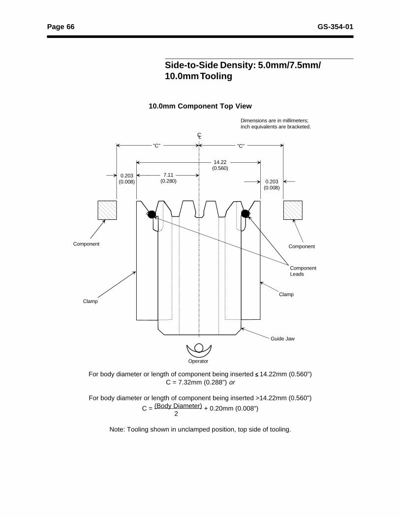
Page 66 GS-354-01
10.0mm Component Top View
Side-to-Side Density: 5.0mm/7.5mm/10.0mm Tooling
For body diameter or length of component being inserted #####14.22mm (0.560")C = 7.32mm (0.288") or
For body diameter or length of component being inserted >14.22mm (0.560")
C = (Body Diameter) + 0.20mm (0.008") 2
Note: Tooling shown in unclamped position, top side of tooling.
Dimensions are in millimeters;inch equivalents are bracketed.
"C"
Component Leads
"C"
Guide Jaw
ClampClamp
Component Component
0.203(0.008)
7.11(0.280)
14.22(0.560)
CL
0.203(0.008)
Operator

Page 67GS-354-01
Stand Alone Workboard Holder
Custom Workboard Holder
Note:
2.5mm components are represented by the shaded holes.
8.18(0.322)
5.64(0.222)
5.64(0.222)
8.18(0.322)
8.18(0.322)
8.18(0.322)
5.64(0.222)
6.60(0.260)
9.14(0.360)
6.60(0.260)
9.14(0.360)
8.18(0.322)
8.18(0.322)
Operator
90° Right
90° Left
0° 0°
90°
N-Type Cut and Clinch(90° Short Lead)
T-Type Cut and Clinch
Dimensions are in millimeters;inch equivalents are bracketed.
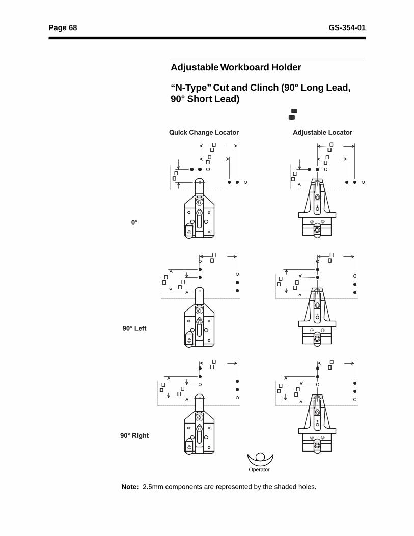
Page 68 GS-354-01
Adjustable Workboard Holder
“N-Type” Cut and Clinch (90° Long Lead,90° Short Lead)
Note: 2.5mm components are represented by the shaded holes.
11.28(0.444)
10.52(0.414)
13.06(0.514)
10.77(0.424)
13.31(0.524)
13.31(0.524)
8.74(0.344)
13.06(0.514)
11.28(0.444) 10.77
(0.424)
13.31(0.524)
13.31(0.524)
8.74(0.344)
13.06(0.514)
11.28(0.444) 10.77
(0.424)
13.31(0.524)
13.31(0.524)
Quick Change Locator Adjustable Locator
Dimensions are in millimeters;inch equivalents are bracketed.
0°
90° Left
90° Right
Operator
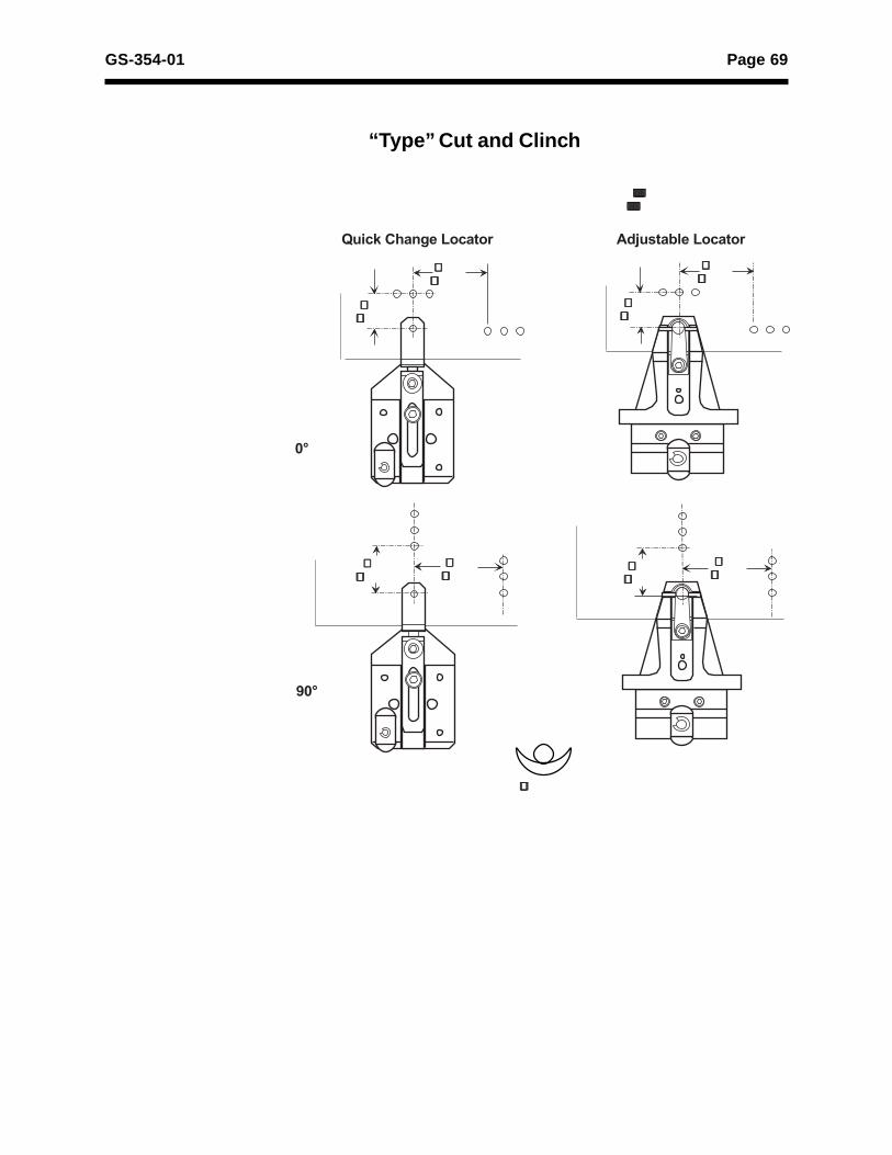
Page 69GS-354-01
“Type” Cut and Clinch
11.28(0.444)
12.04(0.474)
14.07(0.554)
15.53(0.454)
14.07(0.554)
15.53(0.454)
13.81(0.544)
9.50(0.374)
Operator
0°
90°
Quick Change Locator Adjustable Locator
Dimensions are in millimeters;inch equivalents are bracketed.

Page 70 GS-354-01
Board Handling
Board Handling System (BHS) Cut andClinch Edge Clearance Specifications
Cut and Clinch PCB Edge Clearances
“N-Type” Cut and Clinch(90° Long Lead and 90°Short Lead)
D and E = The area that a component insertion center line must notcross when BHS is set to a standard 3mm edge clearance. If BHSis set to 5mm edge clearance, add 2mm (0.08") to thedimensions below.
PCB Locating Arm Dimensions
A 7.12mm (0.280")
B 3.56mm (0.140")
C 4.06mm (0.160")
FApprox. 14.0mm (0.55"), variesaccording to locating hole diameter
“T-Type” Cut and Clinch
Head Rotation
0° 90° Left 90° Right
2.5mm Lead SpanD=8.80mm (0.345")E=8.80mm (0.345")
D=10.0mm (0.394")E=7.52mm (0.296")
D=7.52mm (0.296")E=10.0mm (0.394")
5mm Lead SpanD=8.80mm (0.345")E=8.80mm (0.345")
D=8.80mm (0.345")E=8.80mm (0.345")
D=8.80mm (0.345")E=8.80mm (0.345")
Locating Arm
F
Cross Section of Board
Locating Hole
0° Rotation D and E = 4.62mm (0.182")
90° Rotation D and E = 8.43mm (0.332")
E
DA
B C
Rear
Front

Page 71GS-354-01
“N-Type” 2.5mm/5.0mm/7.5mm (Long Lead, Short Lead)
0° 90°L 90°R
2.5mmD = 7.5mm (0.295")E = 7.5mm (0.295")
D = 7.3mm (0.287")E = 11.6mm (0.457")
D = 11.6mm (0.457")E = 7.3mm (0.287")
5.0mmD = 7.5mm (0.295")
E = 7.5mm (0.295")
D = 8.6mm (0.339")
E = 10.3mm (0.405")
D = 10.3mm (0.405")
E = 8.6mm (0.339")
7.5mmD = 7.5mm (0.295")
E = 7.5mm (0.295")
D = 9.8mm (0.386")
E = 9.0mm (0.354")
D = 9.0mm (0.354")
E = 9.8mm (0.386")
“N-Type” 5.0mm/7.5mm/10.0mm (Long Lead)
0° 90°L 90°R
5.0mmD = 6.5mm (0.256")
E = 6.5mm (0.256")
D = 8.6mm (0.339")
E = 8.6mm (0.339")
D = 8.6mm (0.339")
E = 8.6mm (0.339")
7.5mmD = 6.5mm (0.256")
E = 6.5mm (0.256")
D = 9.8mm (0.386")
E = 7.3mm (0.287")
D = 7.3mm (0.287")
E = 9.8mm (0.386")
10.0mmD = 6.5mm (0.256")E = 6.5mm (0.256")
D = 8.6mm (0.339")E = 8.6mm (0.339")
D = 8.6mm (0.339")E = 8.6mm (0.339")
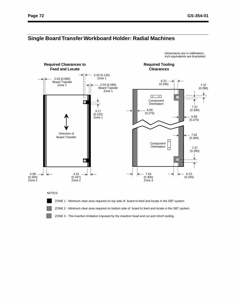
Page 72 GS-354-01
2.03 (0.080)Board Topside
Zone 1
5.08 (0.200)Zone 2
2.03 (0.080)Board Topside
Zone 1
6.22 (0.245)
7.37(0.290)
6.99(0.275)
6.99(0.275)
ZONE 1 - Minimum clear area required on top side of board to feed and locate in the SBT system.
ZONE 2 - Minimum clear area required on bottom side of board to feed and locate in the SBT system.
ZONE 3 - The insertion limitation imposed by the insertion head and cut and clinch tooling.
NOTES:
ComponentOrientation
Dimensions are in millimeters;inch equivalents are bracketed.
3.43 (0.135)Zone 1
3.17 (0.125)Zone 1
Required Clearances to Feed and Locate
Required Tooling Clearances
4.24 (0.167)Zone 2
7.37(0.290)
ComponentOrientation
7.62(0.300)Zone 3
6.22(0.245)
7.37(0.290)
7.62(0.300)
Direction ofBoard Transfer
Single Board Transfer Workboard Holder: Radial Machines
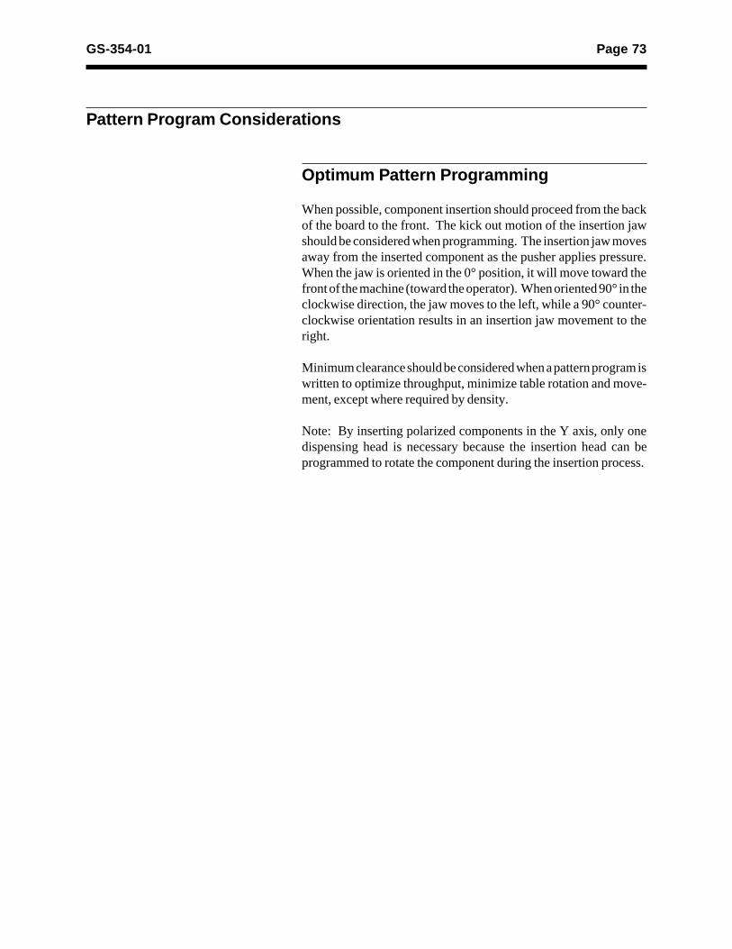
Page 73GS-354-01
Pattern Program Considerations
Optimum Pattern Programming
When possible, component insertion should proceed from the backof the board to the front. The kick out motion of the insertion jawshould be considered when programming. The insertion jaw movesaway from the inserted component as the pusher applies pressure.When the jaw is oriented in the 0° position, it will move toward thefront of the machine (toward the operator). When oriented 90° in theclockwise direction, the jaw moves to the left, while a 90° counter-clockwise orientation results in an insertion jaw movement to theright.
Minimum clearance should be considered when a pattern program iswritten to optimize throughput, minimize table rotation and move-ment, except where required by density.
Note: By inserting polarized components in the Y axis, only onedispensing head is necessary because the insertion head can beprogrammed to rotate the component during the insertion process.
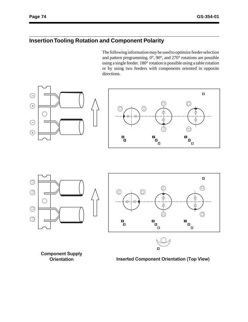
Page 74 GS-354-01
Insertion Tooling Rotation and Component Polarity
The following information may be used to optimize feeder selectionand pattern programming. 0°, 90°, and 270° rotations are possibleusing a single feeder. 180° rotation is possible using a table rotationor by using two feeders with components oriented in oppositedirections.
� +
�+
Inserted at 0° Orientation
Inserted at 270° Orientation
(90° L)
Inserted at 90° Orientation
(90° R)
PC Board
�+
�
+�
+
Inserted at 0° Orientation
Inserted at 270° Orientation
(90° L)
Inserted at 90° Orientation
(90° R)
PC Board
�
+
�
+
+
�
Component Supply Orientation Inserted Component Orientation (Top View)
Operator

Page 75GS-354-01
Dual In-Line Package Insertion
This section has been prepared to assist in the design of printedcircuit boards for use with Universal’s Multi-Module® and Uni-Module® DIP Insertion machines. It is specifically written forModels 6772A and 6774A Multi-Module II machines.
The Multi-Module family includes insertion systems which arecapable of processing a combination of two of the following devices.With optional tooling, the insertion of both DIPs and sockets ispossible.
· If the design requires DIP components only, use DIP toolingspecifications.
· If DIP and socket components are required, use socket toolingspecifications.
7.62(0.300)
7.62(0.300)
10.16 (0.400) – 15.24 (0.600)
7.62(0.300)
15.24 (0.600)
7.62 (0.300) span DIP2 and 4 leads
7.62 (0.300) span DIP6 to 28 leads
10.16 (0.400) span DIP22 and 40 leads
15.24 (0.300) span DIP22 to 42 leads
7.62 (0.300) span socket6 to 28 leads
15.24 (0.600) span socket22 to 42 leads
Dimensions are in millimeters; inchequivalents are bracketed.
Page 76 GS-354-01
Component Input Specifications
Standard DIP IC Modules
4.57 (0.180)
Note 5
1.91 (0.075) MaxBoth Ends
VIEW A
A
Notes:
1. NA
2. For DIP Lead Sense machines, 0.89 (0.035)lead length below the board is required.
3. Measured when leads are parallel to eachother and perpendicular to the componentbody. (Dimension includes solder buildupwhen present.)
4. Ends to be free of flash and irregularities.
5. Bottom to be flat and smooth.
6. Lead pitch within 0.1 (0.004).
7. Lead form to be symmetric about 2.54(0.100) Lead pitch within 0.1 (0.004).
8. Leads to be formed central and parallelwith component body within 0.38 (0.015).Total body skew not to exceed outlineshown in view A.
9. All dimensions shown in this view are to becentral of centerline within 0.25 (0.010).
10. Leads shall be central to DIP module bodywithin 0.25 (0.010) total indicator reading.
11. Component body must be non-transparent.
0.18 (0.007)
Insert Span - 0.25 (0.01) =Max ConditionNote 10
Insert Span + 0.51 (0.02) Note 3 -0.00
Note 9
Note 3
3.05 (0.120)5.59 (0.220)Note 2
0.38 (0.015)
Note 7Note 11
1.78 (0.070)
0.25 (0.010)
0.76 (0.030)0.56 (0.022)0.38 (0.015)
Insert Span - 0.51 (0.02) =Maximum Condition Note 8
VIEW A
Maximum/Miminum dimensions are expressed as:
Millimeter (Inch) = Maximum ConditionMillimeter (Inch) = Minimum Condition
Insert Span-0.51 (0.020)=Min Condition
Insert Span+ 2.54 (0.100) =Max Condition
2.95 (0.116)Maximum
1.52 (0.06 )Max
2.54 ± 0.25(0.100 ± 0.010)Non-cumulative
DIP LEAD NUMBER DIMENSION A INSERT SPAN OF LEADS MINIMUM MAXIMUM
7.62 (0.300) 6-28 7.62 (0.300) 36.83 (1.450)10.16 (0.400) 22-40 27.94 (1.100) 52.07 (2.050)15.24 (0.600) 22-42 27.94 (1.100) 54.61 (2.150)
2.03 (0.080)
Note 7
1.17 (0.046) Max
Note 4
Standard DIP Integrated Circuit Module, 6 through 42 Leads
Dimensions are in millimeters;inch equivalents are bracketed.

Page 77GS-354-01
Side-Brazed DIP IC Modules
4.57 (0.180)
A
Insert Span + 0.51(0.02)
Note 6
Note 4
2.03 (0.080)
3.05 (0.120) Note 25.59 (0.220)
Insert Span+ 2.54 (0.100) =Max Condition
0.36 (0.014)0.18 (0.007)
2.54 ± 0.25 (0.100 ± 0.010)Non-cumulative
Insert Span - 0.51(0.020) =Min Condition
1.52 (0.060)Max
Note 6
PreferredLead EndConfiguration
1.91 (0.075)MaxBoth Ends
Max0.25 (0.010)
0.76 (0.030)1.78 (0.070)
Note 5
Dimensions are in millimeters;inch equivalents are bracketed.
0.38 (0.015)0.56 (0.022)
Note 7
Note 3
1.17 (0.046) Max.
Side-Brazed DIP Integrated Circuit Module, 6 Through 42 Leads
Maximum/Minimum dimensions are expressed as:
Millimeter (Inch) = Maximum ConditionMillimeter (Inch) = Minimum Condition
DIP LEAD NUMBER DIMENSION A
INSERT SPAN OF LEADS MINIMUM MAXIMUM
7.62 (0.300) 6-28 7.62 (0.300) 36.83 (1.450)
10.16 (0.400) 22-40 27.94 (1.100) 52.07 (2.050)
15.24 (0.600) 22-42 27.94 (1.100) 54.61 (2.150)
Notes :
1. NA
2. For DIP Lead Sense machines, 0.89 (0.035) lead length belowthe board is required.
3. Ends to be free of flash and irregularities.
4. Bottom to be flat and smooth.
5. Lead form to be symmetric about 2.54 (0.100) lead pitch within0.1 (0.004).
6. All dimensions shown in this view are to be central of centerlinewithin 0.25 (0.010).
7. Component body must be non-transparent.
Insert Span - 0.00
Insert Span - 0.51(0.02)Insert Span - 0.25 (0.01)

Page 78 GS-354-01
2- and 4-Lead DIP Modules
19°20° Typ.
Note 7
Note 3 Note 3
Note 4
1.62 (0.064)
Note 2
0.56 (0.022)0.38 (0.015)
0.3 (0.012)
7.11 (0.280)Min
10° Ref
0.25 (0.010) RMin
2.36 (0.093)
4.9 (0.193)5.03 (0.198)
7.49 (0.295)
5.59 (0.220)
3.18 (0.125)
2.79 (0.110)2.29 (0.090)
1.52 (0.06)Max
7.62 (0.300)Max
0.76 (0.030)
0.25 (0.010)Max
3.18 (0.125)Min
30°Note 5
1.14 (0.045)
0.15 (0.006)10.16 (0.400)
Max.
Note 62.49 (0.098)
3.18 (0.125)Note 8
0.66 (0.026)
0.25 (0.010) RMin (4 Places)
7.11 (0.280)Max
Note 5
7.62 (0.300)Min
Note 1
6.35 (0.250)6.1 (0.240)
0.36 (0.014)0.18 (0.07)
Notes:
1. Measured at tangent of formed radius.
2. All dimensions shown in this view are to be central to centerlinewithin 0.25 (0.010).
3. Leads shall be on centerline of DIP module body within 0.25(0.010) total indicator reading.
4. Preferred lead configuration.
5. If body width exceeds 6.35 (0.250), 30° chamfer required.
6. Includes all body surface irregularities.
7. Component body must be non-transparent.
8. For DIP Lead Sense machines, 0.89 (0.035) lead length below theboard is required.
Maximum/Minimum dimensions are expressed as:
Millimeter (Inch) = Maximum Condition
Millimeter (Inch) = Minimum Condition
Dimensions are in millimeters;inch equivalents are bracketed.
2 and 4 Lead DIP Integrated Circuit Modules

Page 79GS-354-01
DIP Socket Modules
2.29 (0.090) Max
A B
C
Note 3
0.66 (0.026)Insert Span+ 2.54 (0.100) =Max Cond
0.3 (0.012)0.13 (0.005)
Insert Span± 0.51 (0.020)Note 2 0.25 (0.010)
MaxNote 6
4.06 (0.160)2.54 (0.100)
0.38 (0.015)
Notes:
1. Tolerances are non-cumulative.
2. Leads are to be formed central and parallel with the componentbody within 0.25 (0.010).
3. For DIP Lead Sense machines, 0.89 (0.035) lead length belowthe board is required.
4. Socket body must be non-transparent.
Insert Span- 0.51 (0.020)= Min Cond
Maximum/Minimum dimensions are expressed as:
Millimeter (Inch) = Maximum ConditionMillimeter (Inch) = Minimum Condition
5.84 (0.230)
3.02 (0.120)
Note 4
0.76 (0.030) Max
1.91 (0.075)Max Both Ends
2.54 (0.100)Note 1
Dimensions are in millimeters;inch equivalents are bracketed.
NO. OFLEADS
SOCKETLEADSPAN
DIMENSIONS
A B C
MAX MIN MAX MIN
6-287.62
(0.300)10.41
(0.410)7.62
(0.300)36.8
(1.450)7.62
(0.300)
22-4010.16
(0.400)12.95
(0.510)27.94
(1.100)52.07
(2.050)10.16
(0.400)
22-4215.24
(0.600)18.03
(0.710)27.94
(1.100)54.61
(2.150)15.24
(0.600)

Page 80 GS-354-01
A B
C
Brickwall DIP Socket Modules
Brickwall insertion requires placing socket modules side by side withminimal clearance (for example, 0.25mm or 0.010").
0.13 (0.005)0.3 (0.012)
Insert Span± 0.127 (0.005)Note 2
Insert Span- 0.51 (0.020) =Min Condition
2.29 (0.090)Max
0.13 (0.005) Max
0.66 (0.026)0.38 (0.015)
4.06 (0.160)2.54 (0.100)
Note 3
2.54 (0.100)Note 1
0.76 (0.030)Max
Maximum/Minimum dimensions are expressed as:
Millimeter (Inch) = Maximum ConditionMillimeter (Inch ) = Minimum Condition
5.84 (0.230)3.02 (0.120)
1.91 (0.075)Max BothEndsInsert Span
+ 2.54 (0.100) =Max Condition
Note 4
Dimensions are in millimeters;inch equivalents are bracketed.
Notes:
1. Tolerances are non-cumulative.
2. Leads are to be formed central and parallel with the component body within 0.25(0.010).
3. For DIP Lead Sense machines:• 0.89 (0.035) lead length below the board is required, and• when brickwalling sockets, machined pin type sockets are required.
4. Socket body must be non-transparent.
NO. OFLEADS
SOCKETLEADSPAN
DIMENSIONS
A B C
MAX MIN MAX MIN
6-287.62
(0.300)10.13
(0.399)7.62
(0.300)36.8
(1.450)7.62
(0.300)
22-4010.16
(0.400)12.67
(0.499)27.94
(1.100)50.8
(2.000)10.16
(0.400)
22-4215.24
(0.600)17.75
(0.699)27.94
(1.100)54.61
(2.150)15.24
(0.600)

Page 81GS-354-01
Notes:
1. Tolerances are non-cumulative.
2. Pins to be parallel with the component body within 0.25 (0.010).
3. For DIP Lead Sense machines, 0.89 (0.035) min. lead length below the board is required.
4. Socket body must be non-transparent.
5. Dimension developed from datum A at left lead row and measure to closest pin of right lead row.
6. Machine pin sockets may be brickwall inserted if dimension A conforms to brickwall socket specifications.
Machined Pin DIP Socket Modules
Dimensions are in millimeters;inch equivalents are bracketed.
Note:Tapered bushing recommended for autoinsertion. Non-tapered bushing contributesto reduced insertion reliability.
A B2.25 (0.090) Min5.84 (0.230)
InsertSpan Note 2
Note 4
1.32 (0.052)Max
1.5 (0.06) Max
4.06 (0.160) Min 5.59 (0.220) Max
2.54 (0.100)Note 1
1.9 (0.075) MaxBoth Ends
0.38 (0.015)
0.66 (0.026)
DIMENSIONS
SOCKET PIN A Note 6 B C
INSERT SPAN MAX MIN MAX MIN
7.62 (0.300) 10.41 (0.410) 7.62 (0.300) 25.4 (1.00) 6.35
10.16 (0.400) 12.95 (0.510) 27.94 (1.100) 50.8 (2.00) 8.89
15.24 (0.600) 18.03 (0.710) 27.94 (1.100) 50.8 (2.00) 13.97
Maximum/Minimum dimensions are expressed as:
Millimeter (Inch) = Maximum ConditionMillimeter (Inch) = Minimum Condition
Surface irregularitiespermissible within
shaded area
Non-tapered Entry
Bushing
Wide-tapered Entry
Bushing
C-A- Note 5
Page 82 GS-354-01
Insertion Hole Diameter Considerations
When determining lead hole diameters, two primary factors must beconsidered:
• The holes must be large enough to consistently accept compon-ent lead insertion.
• The holes must be small enough to assure a secure lead clinch.
The minimum component lead hole size required for reliable DIPmodule insertion is a function of:
1. Component lead cross-sectional area and lead-end configura-tion.
2. Machine tolerance and accuracy.3. Workboard holder accuracy.4. Board pattern and tooling reference accuracy.5. Printed circuit board hole positional tolerance.
Minimum Hole Diameter =
Maximum Lead Diameter + Hole Location Tolerance + 0.25mm (0.010")Maximum Lead Diameter = C
C = A² + B²
Component Lead Considerations
Insertion reliability for DIP modules is also influenced by thecondition of the component leads as well as by the lead tip configu-ration.
B
C
A
20° to 30°or
45° to 90°
1.78 (0.070) Max.0.76 (0.030) Min.
30° to 150°
0.25 (0.010)
1.17 (0.022) Max.0.38 (0.015) Min.
Radius 0.36 (0.015) Max.
Acceptable(Squared Lead Tip)
Preferred(Tapered Lead Tip)

Page 83GS-354-01
Clinch Lengths and Angles
Inward Clinch
Outward Clinch
The outward clinch pattern is NOT recommended for DIP socketmodule insertion.
Notes:
1. Tooling change is required to change lead clinch angle or length.
2 Angle may vary depending on lead hardness and hole diameter.
20° + 8°
0.64 ± 0.13(0.025 ±0.005)
DIP SOCKET
A 0° +10°, -0° 40° ± 8°
B 1.02mm (0.040") 1.02mm (0.040")
CMinimum Dimension will be leadthickness up to 0.64mm (0.025")
0.64mm (0.025")
A
B Notes 1 and 2
C

Page 84 GS-354-01
Density Considerations
DIP or DIP Socket Insertion
Notes:
1. Dimensions must clear tooling. Minimum clearance is:7.63mm (0.300"), 6-20 leads = 25.4mm (1.000")
* 7.62mm (0.300"), 6-24 leads = 30.48mm (1.200")10.16mm (0.400"), 22-40 leads = 50.8mm (2.000")15.24mm (0.600"), 22-40 leads = 50.8mm (2.000")
* 15.24mm (0.600"), 22-42 leads = 53.34mm (2.100")
* Indicates optional tooling.
2. Maximum body tolerance plus 0.254mm (0.010") is recommended.
Note 1
Note 2
Note 1
Note 2
DIP Socket
DIP IC Moduleor DIP CocketBeing Inserted
DIP ICModule
2.54 (0.100)Minimum
PreviouslyInserted DIP
Socket
DIP ICModule
DIP IC ModuleBeing Inserted
MachineFront
Component Being Inserted
Component In-place on Circuit Board
2.54 (0.100)Minimum
2.54 (0.100)Minimum
2.54 (0.100)Minimum
Dimensions are in millimeters;inch equivalents are bracketed.
TOOLING FOR INTERMIXINGDIP INTEGRATED CIRCUIT
MODULES AND DIP SOCKETS
TOOLING FORDIP INTEGRATED CIRCUIT
MODULES ONLY

Page 85GS-354-01
Brickwall Insertion
Brickwalling is the high density insertion of DIP sockets intoworkboards. Shown below is an example of socket insertion densityconsiderations.
Notes:
1. Dimensions must clear tooling. Minimum clearance is:7.62mm (0.300") 2 leads = 2.54mm (0.100")7.62mm (0.300") 4 leads = 5.1mm (0.200")
7.62mm (0.300") 6-20 leads = 25.4mm (1.000")* 7.62mm (0.300") 6-24 leads = 30.48mm (1.200")
15.24mm (0.600") 22-40 leads= 50.8mm (2.000")* 15.24mm (0.600") 22-42 leads = 53.34mm (2.100")
* Indicates optional tooling
2. Maximum body tolerance plus 0.254mm (0.010") is recommended.
3. Total tolerance accumulation must be considered with specified socket widths, socket lead location,printed circuit board hole location, and positioning system accuracy to ensure proper clearances.
} Applicable toModel 6774 Tooling
Dimensions are in millimeters;inch equivalents are bracketed.
Note 1
Note 2
DIP Socket
DIP ICModule
2.54 (0.100)
DIP IC Module orDIP Socket Being
Inserted
0.025 (0.001) MinimumNote
2.54 (0.100) Minimum

Page 86 GS-354-01
DIP Tooling to SMT Clearance (Topside)
Dimensions are in millimeters;inch equivalents are bracketed.
0.7 (0.03) Clearance
3.0 (0.120)
2.3 (0.090)
1.5 (0.060)
1.3 (0.050)
1.0 (0.040)
0.7 (0.030)
0.5 (0.020)
SMTComponentThickness
1.98 (0.078)
2.03 (0.080)
2.18 (0.086)
2.28 (0.090)
2.41 (0.095)
2.72 (0.107)
3.05 (0.120)
Centerline of Insertion Hole
Allowable SMD Distance When Inserting DIP

Page 87GS-354-01
Socket Tooling to SMT Clearance (Topside)
DIP INSERTION SOCKET INSERTION
Dimensions are in millimeters;inch equivalents are bracketed.
0.8 (0.030) Clearance
Centerline ofLead Insertion Hole 3.0 (0.12)
2.3 (0.09)
1.5 (0.06)
1.0 (0.04)
1.2 (0.05)
0.8 (0.03)0.5 (0.02)
1.7 (0.067)
1.8 (0.073)
2.0 (0.078)
2.1 (0.084)
2.3 (0.089)
2.7 (0.106)
3.1 (0.122)
SMTComponentThickness
Allowable SMD DistanceWhen Inserting DIP's
3.0 (0.12)
2.3 (0.09)
1.5 (0.06)
1.0 (0.04)
1.2 (0.05)
0.8 (0.03)0.5 (0.02)
SMTComponentThickness
Centerline ofLead Insertion Hole
0.8 (0.030) Clearance
3.6 (0.144)
4.0 (0.159)
4.4 (0.175)
3.1 (0.124)
3.3 (0.129)
3.4 (0.134)
3.5 (0.139)
Allowable SMD DistanceWhen Inserting Sockets
Page 88 GS-354-01
Clinch Tooling to SMT Clearance(Bottomside)
END VIEW
SIDE VIEW
FRONT OFMACHINE
Metric Formula: A = (Tooling Lead Count ) x 2.54 + 2.812
Inch Formula: A = (Tooling Lead Count ) x 0.100 + 0.1112
Dimensions are in millimeters;inch equivalents are bracketed.
A
2.82 (0.111)
DIP Component
Surface MountComponent
Clinch Tooling
ComponentHeight
Distance From
C
3.05 X 21.84 (0.120 X 0.860)
2.29 X 19.81 (0.090 X 0.780)
1.52 X 15.24 (0 060 X 0.600)1.27 X 12.93 (0.050 X 0.509)1.02 X 10.72 (0.040 X 0.334)
0.76 X 8.48 (0.030 X 0.334)
0.51 X 6.25 (0.020 X 0.246)
Page 89GS-354-01
FRONT OF
MACHINE
FRONT OF
MACHINE
FRONT OF
MACHINE
FRONT OF
MACHINE
FRONT OF
MACHINE
A
A
A
FRONT OF
MACHINE
5.71(0.225)
13.0(0.512)
6.35(0.250)
22.10(0.870)
8.64(0.340)
22.10(0.870)
Quick ChangeLocator
AdjustableLocator
Dimensions are in millimeters;inch equivalents are bracketed.
Metric Formula : A = TOOLING LEAD COUNT X 2.54 + .8.13
Inch Formula : A = TOOLING LEAD COUNT X 0.1 + 0.320 2
2
Metric formula: A = TOOLING LEAD COUNT x 2.54 + 5.71
Inch formula: A = TOOLING LEAD COUNT x 0.1 + 0.225
Stand Alone Workboard Holder
Custom Workboard Holder
Adjustable Workboard Holder
2
2
Metric Formula: A = TOOLING LEAD COUNTX 2.54 + 12.50
Inch Formula: A = TOOLING LEAD COUNT X 0.1 + 0.4922
2

Page 90 GS-354-01
Board Handling
Single Board Transfer Workboard Holder:Dual In-Line Packages(Table Positioned at 0° Rotation)
4.24 (0.167)
Zone 1 - Minimum clear area required on top side of work board to feed and locate in the SBT system.
Zone 2 - Minimum clear area required on bottom side of work board to feed and locate in the SBT system.
Zone 3 - The insertion limitation imposed by the insertion head and cut and clinch tooling.
All dimensions apply to7.62 & 15.24 (0.300 & 0.600)tooling configurations.
Dimensions are in millimeters;inch equivalents are bracketed.
NOTES:
TOOLING ORIENTATION
MACHINE FRONT (REF.)
3.17 (0.1250)
4.24 (0.167)
3.17 (0.125)
21.59 (0.420)
2.03 (0.080)
5.56 (0.219) Zone 3
A
5.23 (0.206)
5.56 (0.219)
Operator
Metric formula: A = TOOLING LEAD COUNT CAPACITY x 2.54 + 5.56
Inch formula: A = TOOLING LEAD COUNTCAPACITY x 0.100 + 0.219
2
2
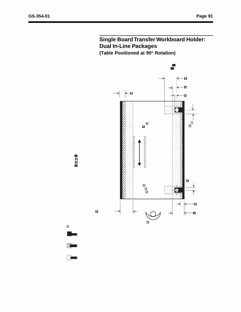
Page 91GS-354-01
Single Board Transfer Workboard Holder:Dual In-Line Packages(Table Positioned at 90° Rotation)
21.59 (0.420)
8.26 (0.325)
3.17 (0.125)4.24 (0.167)
5.21 (0.205)
3.17 (0.125)
4.24 (0.167)
17.78 (0.700)17.78 (0.700)
Zone 1 - Minimum clear area required on top side of work board to feed and locate in the SBT system.
Zone 2 - Minimum clear area required on bottom side of work board to feed and locate in the SBT system.
Zone 3 - The insertion limitation imposed by the insertion head and cut and clinch tooling.
All dimensions apply to7.62 & 15.24(0.300 & 0.600)tooling configurations.
Dimensions are in millimeters;inch equivalents are bracketed.
MACHINEFRONT(REF.)
NOTES:
TOOLINGORIENTATION
Operator
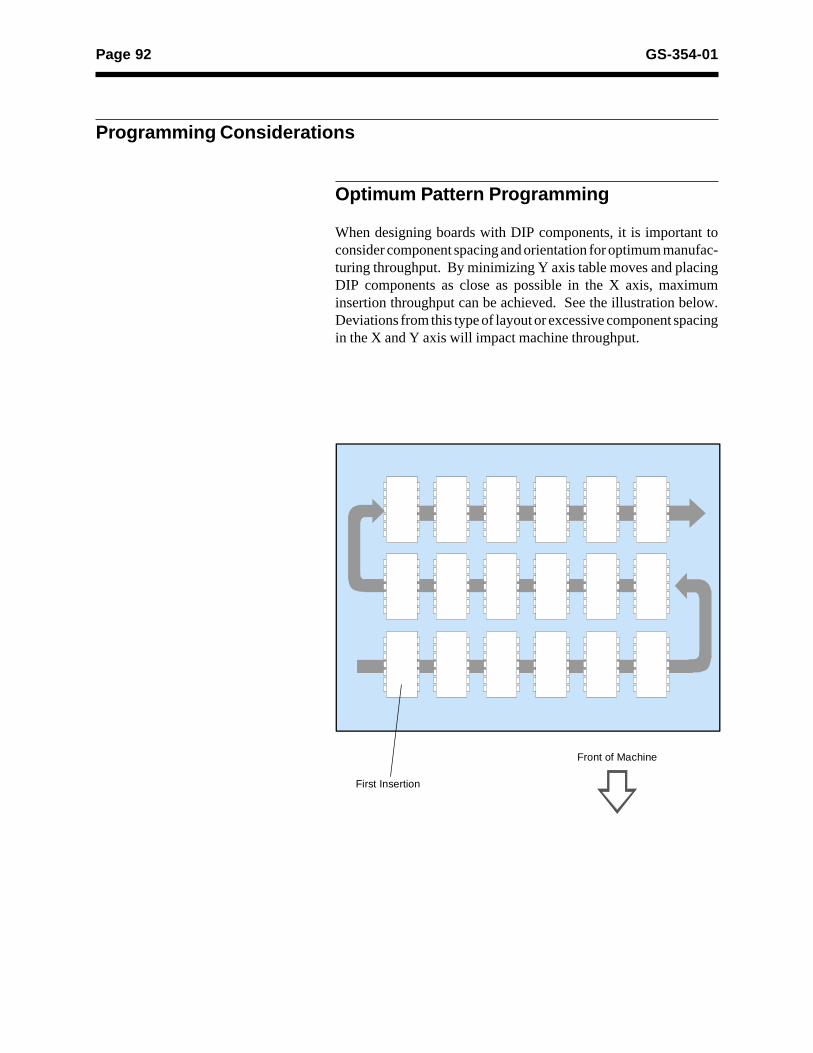
Page 92 GS-354-01
Programming Considerations
Optimum Pattern Programming
When designing boards with DIP components, it is important toconsider component spacing and orientation for optimum manufac-turing throughput. By minimizing Y axis table moves and placingDIP components as close as possible in the X axis, maximuminsertion throughput can be achieved. See the illustration below.Deviations from this type of layout or excessive component spacingin the X and Y axis will impact machine throughput.
Front of Machine
First Insertion