
General-purpose Relay G2RS-(S) - Omron Electronic Components

Cat. No. N148-E1-02 Three-phase Voltage Relay K8AB-PW 1
Three-phase Voltage RelayK8AB-PW
Ideal for monitoring 3-phase power supplies for industrial facilities and equipment.
• Monitor overvoltages and undervoltages for three-phase 3-wire or 4-wire power supplies. DIP switch setting for 3-phase 3-wire or 3-phase 4-wire power supply.
• Two SPDT output relays, 6 A at 250 VAC (resistive load).Separate outputs possible for overvoltages and undervoltages.
• World-wide power specifications supported by one Unit (switchable using DIP switch).
• Relay status can be monitored using LED indicator.
Model Number Structure
Model Number Legend
1. Basic ModelK8AB: Measuring and Monitoring Relays
2. FunctionsPW: Three-phase Voltage Relay (Simultaneous upper and lower monitoring)
3. Rated Input Voltage1: 115, 127, 133, 138, 200, 220, 230, 240 VAC2: 220, 230, 240, 277, 380, 400, 415, 480 VAC
Single K8AB Monitors 3-phase Power Supply with 3 or 4 WiresMonitoring Relays can be used to monitor 3-phase power supplies with 3 or 4 wires simply by changing DIP switch settings.
A Single K8AB Can Monitor a 3-phase Power Supply Anywhere in the World
Reduces Maintenance Parts Inventory
SW3 ON ON OFF OFFSW4 ON OFF ON OFF
K8AB-P@1SW2
ON P-N 138V 133V 127V 115VOFF P-P 240V 230V 220V 200V
K8AB-P@2SW2
ON P-N 277V 240V 230V 220VOFF P-P 480V 415V 400V 380V
1 2 3K8AB-@@
Phase to phase voltage (3 wires) Phase to neutral voltage (4 wires)
L1 L2 L3 L1 L2 L3 N
400VAC
400VAC
400VAC
230VAC
230VAC
230VAC

2 Three-phase Voltage Relay K8AB-PW Cat. No. N148-E1-02
Ordering Information
List of Models
Note: 1. Three-phase, three-wire or four-wire and the input range are switched using a DIP switch.2. The power supply voltage is the same as the rated input voltage.
Three-phase Voltage Relay Rated input (See note 2.) Model
3-phase 3-wire mode 200, 220, 230, 240 VAC K8AB-PW1
3-phase 4-wire mode 115, 127, 133, 138 VAC
3-phase 3-wire mode 380, 400, 415, 480 VAC K8AB-PW2
3-phase 4-wire mode 220, 230, 240, 277 VAC
Cat. No. N148-E1-02 Three-phase Voltage Relay K8AB-PW 3
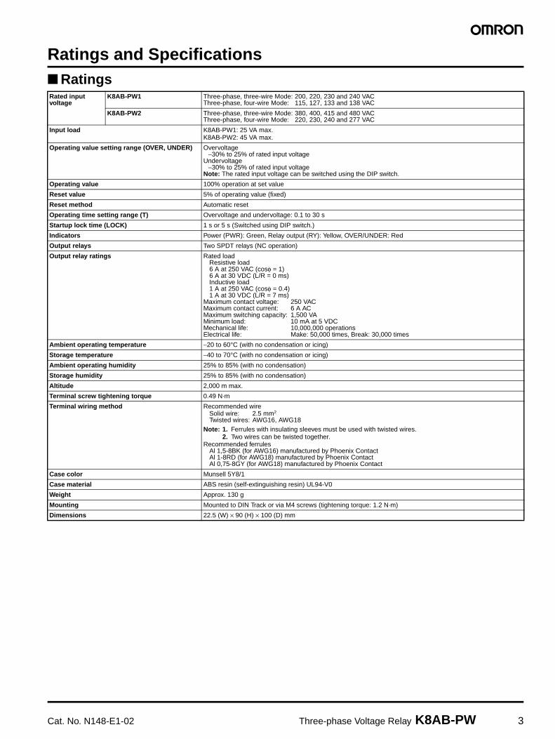
Ratings and Specifications RatingsRated input voltage
K8AB-PW1 Three-phase, three-wire Mode: 200, 220, 230 and 240 VACThree-phase, four-wire Mode: 115, 127, 133 and 138 VAC
K8AB-PW2 Three-phase, three-wire Mode: 380, 400, 415 and 480 VACThree-phase, four-wire Mode: 220, 230, 240 and 277 VAC
Input load K8AB-PW1: 25 VA max.K8AB-PW2: 45 VA max.
Operating value setting range (OVER, UNDER) Overvoltage−30% to 25% of rated input voltage
Undervoltage−30% to 25% of rated input voltage
Note: The rated input voltage can be switched using the DIP switch.
Operating value 100% operation at set value
Reset value 5% of operating value (fixed)
Reset method Automatic reset
Operating time setting range (T) Overvoltage and undervoltage: 0.1 to 30 s
Startup lock time (LOCK) 1 s or 5 s (Switched using DIP switch.)
Indicators Power (PWR): Green, Relay output (RY): Yellow, OVER/UNDER: Red
Output relays Two SPDT relays (NC operation)
Output relay ratings Rated loadResistive load6 A at 250 VAC (cosφ = 1)6 A at 30 VDC (L/R = 0 ms)Inductive load1 A at 250 VAC (cosφ = 0.4)1 A at 30 VDC (L/R = 7 ms)
Maximum contact voltage: 250 VACMaximum contact current: 6 A ACMaximum switching capacity: 1,500 VAMinimum load: 10 mA at 5 VDCMechanical life: 10,000,000 operationsElectrical life: Make: 50,000 times, Break: 30,000 times
Ambient operating temperature −20 to 60°C (with no condensation or icing)
Storage temperature −40 to 70°C (with no condensation or icing)
Ambient operating humidity 25% to 85% (with no condensation)
Storage humidity 25% to 85% (with no condensation)
Altitude 2,000 m max.
Terminal screw tightening torque 0.49 N·m
Terminal wiring method Recommended wireSolid wire: 2.5 mm2
Twisted wires: AWG16, AWG18Note: 1. Ferrules with insulating sleeves must be used with twisted wires.
2. Two wires can be twisted together.Recommended ferrules
Al 1,5-8BK (for AWG16) manufactured by Phoenix ContactAl 1-8RD (for AWG18) manufactured by Phoenix ContactAl 0,75-8GY (for AWG18) manufactured by Phoenix Contact
Case color Munsell 5Y8/1
Case material ABS resin (self-extinguishing resin) UL94-V0
Weight Approx. 130 g
Mounting Mounted to DIN Track or via M4 screws (tightening torque: 1.2 N·m)
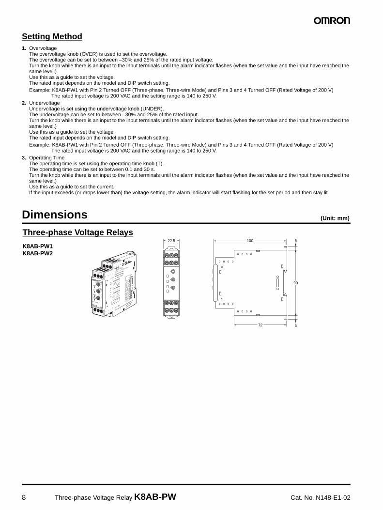
Dimensions 22.5 (W) × 90 (H) × 100 (D) mm
4 Three-phase Voltage Relay K8AB-PW Cat. No. N148-E1-02
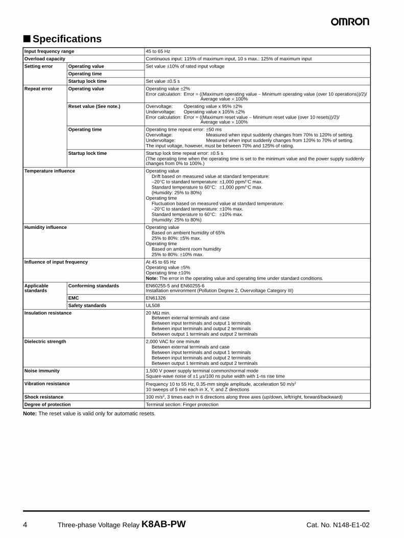
Specifications
Note: The reset value is valid only for automatic resets.
Input frequency range 45 to 65 Hz
Overload capacity Continuous input: 115% of maximum input, 10 s max.: 125% of maximum input
Setting error Operating value Set value ±10% of rated input voltage
Operating time
Startup lock time Set value ±0.5 s
Repeat error Operating value Operating value ±2%Error calculation: Error = ((Maximum operating value − Minimum operating value (over 10 operations))/2)/
Average value × 100%
Reset value (See note.) Overvoltage: Operating value x 95% ±2%Undervoltage: Operating value x 105% ±2%Error calculation: Error = ((Maximum reset value − Minimum reset value (over 10 resets))/2)/
Average value × 100%
Operating time Operating time repeat error: ±50 msOvervoltage: Measured when input suddenly changes from 70% to 120% of setting.Undervoltage: Measured when input suddenly changes from 120% to 70% of setting.The input voltage, however, must be between 70% and 125% of rating.
Startup lock time Startup lock time repeat error: ±0.5 s(The operating time when the operating time is set to the minimum value and the power supply suddenly changes from 0% to 100%.)
Temperature influence Operating valueDrift based on measured value at standard temperature:−20°C to standard temperature: ±1,000 ppm/°C max.Standard temperature to 60°C: ±1,000 ppm/°C max.(Humidity: 25% to 80%)
Operating timeFluctuation based on measured value at standard temperature:−20°C to standard temperature: ±10% max.Standard temperature to 60°C: ±10% max.(Humidity: 25% to 80%)
Humidity influence Operating valueBased on ambient humidity of 65%25% to 80%: ±5% max.
Operating timeBased on ambient room humidity25% to 80%: ±10% max.
Influence of input frequency At 45 to 65 HzOperating value ±5%Operating time ±10%Note: The error in the operating value and operating time under standard conditions.
Applicable standards
Conforming standards EN60255-5 and EN60255-6Installation environment (Pollution Degree 2, Overvoltage Category III)
EMC EN61326
Safety standards UL508
Insulation resistance 20 MΩ min.Between external terminals and caseBetween input terminals and output 1 terminalsBetween input terminals and output 2 terminalsBetween output 1 terminals and output 2 terminals
Dielectric strength 2,000 VAC for one minuteBetween external terminals and caseBetween input terminals and output 1 terminalsBetween input terminals and output 2 terminalsBetween output 1 terminals and output 2 terminals
Noise immunity 1,500 V power supply terminal common/normal modeSquare-wave noise of ±1 µs/100 ns pulse width with 1-ns rise time
Vibration resistance Frequency 10 to 55 Hz, 0.35-mm single amplitude, acceleration 50 m/s2
10 sweeps of 5 min each in X, Y, and Z directions
Shock resistance 100 m/s2, 3 times each in 6 directions along three axes (up/down, left/right, forward/backward)
Degree of protection Terminal section: Finger protection

Cat. No. N148-E1-02 Three-phase Voltage Relay K8AB-PW 5
Connections
Wiring DiagramOvervoltage and Undervoltage Operation Diagram
Note: 1. K8AB-PW output relay is normally operative.2. The power ON lock function prevents unnecessary alarms from
being generated during the unstable period when the power is first turned ON. There is no relay output during timer operation.
3. L1 and L2 use the same power supply and will not operate due to an undervoltage if they drop below the rated input of 60%.
T
T1
T
L1L2L3
Hysteresis: Fixed at 5%
Hysteresis: Fixed at 5%
T: Operating time (0.1 to 30 s)
T1: Power ON lock (1 s or 5 s)
Flashing Lit
Flashing
LitOvervoltage alarm indicator
Undervoltage alarm indicator
Overvoltage relay
Undervoltage relay
Undervoltage setting value
Overvoltagesetting value
Input
T: Operating time (0.1 to 30 s)
Load
Voltage input
Signal output14
12
L1
L2
L3
11
L1N L2 L3
Signal output24
22
21
Undervoltagealarm
Overvoltagealarm
N
6 Three-phase Voltage Relay K8AB-PW Cat. No. N148-E1-02
Nomenclature
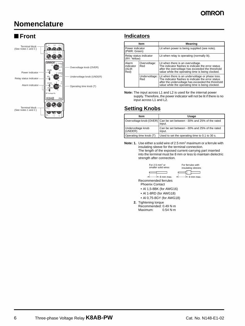
Front Indicators
Note: The input across L1 and L2 is used for the internal power supply. Therefore, the power indicator will not be lit if there is no input across L1 and L2.
Setting Knobs
Note: 1. Use either a solid wire of 2.5 mm2 maximum or a ferrule with insulating sleeve for the terminal connection.The length of the exposed current-carrying part inserted into the terminal must be 8 mm or less to maintain dielectric strength after connection.
Recommended ferrulesPhoenix Contact• Al 1,5-8BK (for AWG16)• Al 1-8RD (for AWG18)• Al 0,75-8GY (for AWG18)
2. Tightening torqueRecommended: 0.49 N·mMaximum: 0.54 N·m
Power indicator
Relay status indicator
Overvoltage knob (OVER)
Undervoltage knob (UNDER)
Operating time knob (T)Alarm indicator
Terminal block(See notes 1 and 2.)
Terminal block(See notes 1 and 2.)
Item Meaning
Power indicator (PWR: Green)
Lit when power is being supplied (see note).
Relay status indicator(RY: Yellow)
Lit when relay is operating (normally lit).
Alarmindicator(ALM: Red)
Overvoltage:Red
Lit when there is an overvoltage.The indicator flashes to indicate the error status after the overvoltage has exceeded the threshold value while the operating time is being clocked.
Undervoltage:Red
Lit when there is an undervoltage or phase loss.The indicator flashes to indicate the error status after the undervoltage has exceeded the threshold value while the operating time is being clocked.
Item Usage
Overvoltage knob (OVER) Can be set between −30% and 25% of the rated input.
Undervoltage knob (UNDER)
Can be set between −30% and 25% of the rated input.
Operating time knob (T) Used to set the operating time to 0.1 to 30 s.
For 2.5 mm2 or smaller solid wires
For ferrules with insulating sleeves
8 mm max. 8 mm max.
Cat. No. N148-E1-02 Three-phase Voltage Relay K8AB-PW 7
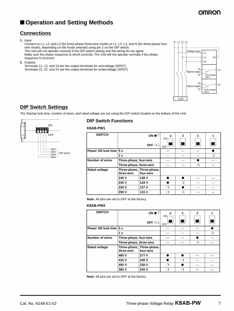
Operation and Setting Methods
Connections1. Input
Connect to L1, L2, and L3 (for three-phase three-wire mode) or L1, L2, L3, and N (for three-phase four-wire mode), depending on the mode selected using pin 2 on the DIP switch.The Unit will not operate correctly if the DIP switch setting and the wiring do not agree. Make sure the phase sequence is wired correctly. The Unit will not operate normally if the phase sequence is incorrect.
2. OutputsTerminals 11, 12, and 14 are the output terminals for overvoltage (SPDT).Terminals 21, 22, and 24 are the output terminals for undervoltage (SPDT).
DIP Switch SettingsThe Startup lock time, number of wires, and rated voltage are set using the DIP switch located on the bottom of the Unit.
Load
Voltage input
Signal output14
12
L1
L2
L3
11
L1N L2 L3
Signal output24
22
21
Undervoltagealarm
Overvoltagealarm
N
ON
OFF
SW1SW2SW3SW4
DIP switch
DIP Switch Functions
K8AB-PW1
Note: All pins are set to OFF at the factory.
K8AB-PW2
Note: All pins are set to OFF at the factory.
SWITCH ON ↑
OFF ↓
Power ON lock time 5 s --- --- ---
1 s --- --- ---
Number of wires Three-phase, four-wire --- --- ---
Three-phase, three-wire --- --- ---
Rated voltage Three-phase,three-wire
Three-phase,four-wire
240 V 138 V --- ---
230 V 133 V --- ---
220 V 127 V --- ---
200 V 115 V --- ---
SWITCH ON ↑
OFF ↓
Power ON lock time 5 s --- --- ---
1 s --- --- ---
Number of wires Three-phase, four-wire --- --- ---
Three-phase, three-wire --- --- ---
Rated voltage Three-phase,three-wire
Three-phase,four-wire
480 V 277 V --- ---
415 V 240 V --- ---
400 V 230 V --- ---
380 V 220 V --- ---
ON
OFF
4ON
OFF
4 33 2 1
ON
OFF
4ON
OFF
4 33 2 1
8 Three-phase Voltage Relay K8AB-PW Cat. No. N148-E1-02
Setting Method1. Overvoltage
The overvoltage knob (OVER) is used to set the overvoltage.The overvoltage can be set to between −30% and 25% of the rated input voltage.Turn the knob while there is an input to the input terminals until the alarm indicator flashes (when the set value and the input have reached the same level.)Use this as a guide to set the voltage.The rated input depends on the model and DIP switch setting.Example: K8AB-PW1 with Pin 2 Turned OFF (Three-phase, Three-wire Mode) and Pins 3 and 4 Turned OFF (Rated Voltage of 200 V)
The rated input voltage is 200 VAC and the setting range is 140 to 250 V.2. Undervoltage
Undervoltage is set using the undervoltage knob (UNDER).The undervoltage can be set to between −30% and 25% of the rated input.Turn the knob while there is an input to the input terminals until the alarm indicator flashes (when the set value and the input have reached the same level.)Use this as a guide to set the voltage.The rated input depends on the model and DIP switch setting.Example: K8AB-PW1 with Pin 2 Turned OFF (Three-phase, Three-wire Mode) and Pins 3 and 4 Turned OFF (Rated Voltage of 200 V)
The rated input voltage is 200 VAC and the setting range is 140 to 250 V.3. Operating Time
The operating time is set using the operating time knob (T).The operating time can be set to between 0.1 and 30 s.Turn the knob while there is an input to the input terminals until the alarm indicator flashes (when the set value and the input have reached the same level.)Use this as a guide to set the current.If the input exceeds (or drops lower than) the voltage setting, the alarm indicator will start flashing for the set period and then stay lit.
Dimensions (Unit: mm)
22.5 100
72
90
5
5
Three-phase Voltage Relays
K8AB-PW1K8AB-PW2
Cat. No. N148-E1-02 Three-phase Voltage Relay K8AB-PW 9
Safety Precautions
Precautions for Safe UseMake sure to follow the instructions below to ensure safety.
1. Do not use or keep this product in the following environments.• Outdoors, or places subject to direct sunlight or wearing
weather.
• Places where dust, iron powder, or corrosive gases (in particular, sulfuric or ammonia gas) exist.
• Places subject to static electricity or inductive noise.
• Places where water or oil come in contact with the product.
2. Make sure to install this product in the correct direction.3. There is a remote risk of electric shock. Do not touch terminals
while electricity is being supplied.4. Make sure to thoroughly understand all instructions in the
Instructions Manual before handling this product.5. Make sure to confirm terminal makings and polarity for correct
wiring.6. Tighten terminal screws firmly using the following torque.
Recommended tightening torque: 0.49 N·mMaximum tightening torque: 0.54 N·m max.
7. Operating ambient temperature and humidity for this product must be within the indicated rating when using this product.
8. There is a remote risk of explosion. Do not use this product where flammable or explosive gas exists.
9. Make sure that no weight rests on the product after installation.10.To enable an operator to turn off this product easily, install
switches or circuit breakers that conform to relevant requirements of IEC60947-1 and IEC60947-3, and label them appropriately.
Precautions for Correct Use
For Proper Use1. Do not use the product in the following locations.
• Places subject to radiant heat from heat generating devices.
• Places subject to vibrations or physical shocks.
2. Make sure to use setting values appropriate for the controlled object. Failure to do so can cause unintended operation, and may result in accident or corruption of the product.
3. Do not use thinner or similar solvent for cleaning. Use commercial alcohol.
4. When discarding, properly dispose of the product as industrial waste.
5. Only use this product within a board whose structure allows no possibility for fire to escape.
About Installation1. When wiring, use only recommended crimp terminals.2. Do not block areas around the product for proper dissipation of
heat. (If you do not secure space for heat dissipation, life cycle of the product will be compromised.)
3. To avoid electrical shocks, make sure that power is not supplied to the product while wiring.
4. To avoid electrical shocks, make sure that power is not supplied to the product when performing DIP switch settings.
Noise Countermeasures1. Do not install the product near devices generating strong high
frequency waves or surges.2. When using a noise filter, check the voltage and current and
install it as close to the product as possible.3. In order to prevent inductive noise, wire the lines connected to the
product separately from power lines carrying high voltages or currents. Do not wire in parallel with or on the same cable as power lines. Other measures for reducing noise include running lines along separate ducts and using shield lines.
To avoid faulty operations, malfunctions, or failure, observe the following operating instructions.1. When turning on the power, make sure to realize rated voltage
within 1 second from the time of first supply of electricity.2. Make sure to use power supply for operations, inputs, and
transformer with the appropriate capacity and rated burden.3. Maintenance and handling of this product may only be performed
by qualified personnel.4. Distortion ratio of input wave forms must be 30% or less. Use of
this product with circuits that have large distortion in wave forms may result in unwanted operations.
5. Using this product for thyristor controls or inverters will result in errors.
6. When setting the volume, adjust the control from the minimum side to the maximum side.
10 Three-phase Voltage Relay K8AB-PW Cat. No. N148-E1-02
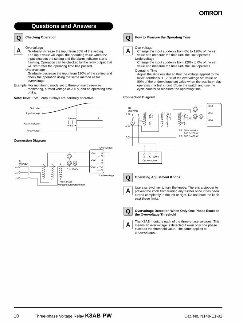
Checking Operation
OvervoltageGradually increase the input from 80% of the setting.The input value will equal the operating value when the input exceeds the setting and the alarm indicator starts flashing. Operation can be checked by the relay output that will start after the operating time has passed.
UndervoltageGradually decrease the input from 120% of the setting and check the operation using the same method as for overvoltage.
Example: For monitoring mode set to three-phase three-wire monitoring, a rated voltage of 200 V, and an operating time of 5 s.
Note: K8AB-PW@ output relays are normally operative.
Connection Diagram
How to Measure the Operating Time
OvervoltageChange the input suddenly from 0% to 120% of the set value and measure the time until the Unit operates.
UndervoltageChange the input suddenly from 120% to 0% of the set value and measure the time until the Unit operates.
Operating TimeAdjust the slide resistor so that the voltage applied to the K8AB terminals is 120% of the overvoltage set value or 80% of the undervoltage set value when the auxiliary relay operates in a test circuit. Close the switch and use the cycle counter to measure the operating time.
Connection Diagram
Operating Adjustment Knobs
Use a screwdriver to turn the knobs. There is a stopper to prevent the knob from turning any further once it has been turned completely to the left or right. Do not force the knob past these limits.
Overvoltage Detection When Only One Phase Exceeds the Overvoltage Threshold
The K8AB monitors each of the three-phase voltages. This means an overvoltage is detected if even only one phase exceeds the threshold value. The same applies to undervoltages.
Questions and Answers
Q
Set value
Input voltage
Alarm indicator
Relay output
Flashing Lit
5 s
0 to 150 V
V1
Three-phase variable autotransformer
L1
L2
L3
3φ,200 VAC V2 V3
L1
L2
L3
Overvoltage
Undervoltage
Q
L1
L2
L3
± C 200 V
Cycle counter
V1
V2 V3
X X/aX/b
L1
L2
L3
R1
R2
R1: Slide resistor 200 Ω 200 WR2: 100 Ω 400 W
3φ,200 VAC
Q
Q

Cat. No. N148-E1-02 Three-phase Voltage Relay K8AB-PW 11
ALL DIMENSIONS SHOWN ARE IN MILLIMETERS.To convert millimeters into inches, multiply by 0.03937. To convert grams into ounces, multiply by 0.03527.
Authorized Distributor:
In the interest of product improvement, specifications are subject to change without notice.
Cat. No. N148-E1-02Printed in Japan
0706-0.7M (0505) (C)
© OMRON Corporation 2005 All Rights Reserved.
OMRON Corporation Industrial Automation Company
OMRON ELECTRONICS LLCOne Commerce Drive Schaumburg,IL 60173-5302 U.S.A.Tel: (1) 847-843-7900/Fax: (1) 847-843-7787
Regional HeadquartersOMRON EUROPE B.V.Wegalaan 67-69-2132 JD HoofddorpThe NetherlandsTel: (31)2356-81-300/Fax: (31)2356-81-388
Contact: www.ia.omron.comTokyo, JAPAN
OMRON ASIA PACIFIC PTE. LTD.No. 438A Alexandra Road # 05-05/08 (Lobby 2), Alexandra Technopark, Singapore 119967Tel: (65) 6835-3011/Fax: (65) 6835-2711
OMRON (CHINA) CO., LTD.Room 2211, Bank of China Tower, 200 Yin Cheng Zhong Road, PuDong New Area, Shanghai, 200120, ChinaTel: (86) 21-5037-2222/Fax: (86) 21-5037-2200
Warranty and Application ConsiderationsRead and Understand this Catalog
Please read and understand this catalog before purchasing the products. Please consult your OMRON representative if you have any questions or comments.
Warranty and Limitations of Liability
WARRANTYOMRON's exclusive warranty is that the products are free from defects in materials and workmanship for a period of one year (or other period if specified) from date of sale by OMRON.OMRON MAKES NO WARRANTY OR REPRESENTATION, EXPRESS OR IMPLIED, REGARDING NON-INFRINGEMENT, MERCHANTABILITY, OR FITNESS FOR PARTICULAR PURPOSE OF THE PRODUCTS. ANY BUYER OR USER ACKNOWLEDGES THAT THE BUYER OR USER ALONE HAS DETERMINED THAT THE PRODUCTS WILL SUITABLY MEET THE REQUIREMENTS OF THEIR INTENDED USE. OMRON DISCLAIMS ALL OTHER WARRANTIES, EXPRESS OR IMPLIED.
LIMITATIONS OF LIABILITYOMRON SHALL NOT BE RESPONSIBLE FOR SPECIAL, INDIRECT, OR CONSEQUENTIAL DAMAGES, LOSS OF PROFITS, OR COMMERCIAL LOSS IN ANY WAY CONNECTED WITH THE PRODUCTS, WHETHER SUCH CLAIM IS BASED ON CONTRACT, WARRANTY, NEGLIGENCE, OR STRICT LIABILITY.In no event shall the responsibility of OMRON for any act exceed the individual price of the product on which liability is asserted.IN NO EVENT SHALL OMRON BE RESPONSIBLE FOR WARRANTY, REPAIR, OR OTHER CLAIMS REGARDING THE PRODUCTS UNLESS OMRON'S ANALYSIS CONFIRMS THAT THE PRODUCTS WERE PROPERLY HANDLED, STORED, INSTALLED, AND MAINTAINED AND NOT SUBJECT TO CONTAMINATION, ABUSE, MISUSE, OR INAPPROPRIATE MODIFICATION OR REPAIR.
Application Considerations
SUITABILITY FOR USEOMRON shall not be responsible for conformity with any standards, codes, or regulations that apply to the combination of products in the customer's application or use of the products.Take all necessary steps to determine the suitability of the product for the systems, machines, and equipment with which it will be used.Know and observe all prohibitions of use applicable to this product.NEVER USE THE PRODUCTS FOR AN APPLICATION INVOLVING SERIOUS RISK TO LIFE OR PROPERTY WITHOUT ENSURING THAT THE SYSTEM AS A WHOLE HAS BEEN DESIGNED TO ADDRESS THE RISKS, AND THAT THE OMRON PRODUCTS ARE PROPERLY RATED AND INSTALLED FOR THE INTENDED USE WITHIN THE OVERALL EQUIPMENT OR SYSTEM.
Disclaimers
PERFORMANCE DATAPerformance data given in this catalog is provided as a guide for the user in determining suitability and does not constitute a warranty. It may represent the result of OMRON's test conditions, and the users must correlate it to actual application requirements. Actual performance is subject to the OMRON Warranty and Limitations of Liability.
CHANGE IN SPECIFICATIONSProduct specifications and accessories may be changed at any time based on improvements and other reasons. Consult with your OMRON representative at any time to confirm actual specifications of purchased product.
DIMENSIONS AND WEIGHTSDimensions and weights are nominal and are not to be used for manufacturing purposes, even when tolerances are shown.
CSM_1_4_0813


![The SOLUTIONS Relay Defects [General-purpose Relay Edition] · Title: The SOLUTIONS Relay Defects [General-purpose Relay Edition] Author: OMRON Keywords: Z384-E1-01 1216(1216) Created](https://static.fdocuments.in/doc/165x107/5f888cabfaba7c0dbe0691e4/the-solutions-relay-defects-general-purpose-relay-edition-title-the-solutions.jpg)


