Three-phase synchronous motors DSD 28 - 36 - Mercado … THREE... · Three-phase synchronous motors...
144
Transcript of Three-phase synchronous motors DSD 28 - 36 - Mercado … THREE... · Three-phase synchronous motors...

Three-phase synchronous motors DSD 28 - 36
DSD 28 - 36 04/08 Technical alterations reservedBaumüller Nürnberg GmbH 1
Table of contents
1. Three-phase synchronous motors DSD 28 - 36...................................................................................... 2 1.1. General technical data ................................................................................................................................ 2 1.2. Definition of ratings...................................................................................................................................... 3 1.3. Winding insulation and temperature rise..................................................................................................... 3 1.4. Explanation of the motor data ..................................................................................................................... 3 1.5. Type key...................................................................................................................................................... 4 2. Technical data ............................................................................................................................................ 5 2.1. DSD028....................................................................................................................................................... 5 2.2. DSD036..................................................................................................................................................... 10 2.3. Radial force diagrams ............................................................................................................................... 18 3. Motor components (options) .................................................................................................................. 20 3.1. Holding brake ............................................................................................................................................ 20 3.2. Encoder ..................................................................................................................................................... 21
3.2.1. Resolver...................................................................................................................................... 21 3.2.2. SINCOS SRS/SRM 50, SKS/SKM 36 (Sick-Stegmann)............................................................. 22
3.3. Encoder cables.......................................................................................................................................... 23 3.3.1. Technical data............................................................................................................................. 23 3.3.2. Application notes......................................................................................................................... 24 3.3.3. Ordering data for encoder cables ............................................................................................... 24
3.4. Motor cables.............................................................................................................................................. 25 3.4.1. Technical data............................................................................................................................. 25 3.4.2. Main connection via connector ................................................................................................... 25 3.4.3. Application notes......................................................................................................................... 26 3.4.4. Ordering data for main connection cables.................................................................................. 26
3.5. Connectors for main connection and encoder .......................................................................................... 27 3.6. Thermal sensor ......................................................................................................................................... 28 4. Dimension drawing.................................................................................................................................. 29 4.1. DSD028 dimension drawings.................................................................................................................... 29 4.2. DSD036 dimension drawings.................................................................................................................... 30 5. Commissioning and maintenance instructions.................................................................................... 31 6. Declaration of Conformity/Manufacturer's Declaration ....................................................................... 31 6.1. What is an EC directive ............................................................................................................................. 31 6.2. What does the CE mark signify?............................................................................................................... 31 6.3. Declaration of Conformity, definition of term............................................................................................. 32 6.4. Manufacturer's Declaration, definition of term........................................................................................... 32 6.5. EU – Declaration of Conformity................................................................................................................. 33 All the details in this list constitute non-binding customer information. These details are subject to ongoing change and are constantly updated by our editing staff. Please note that all details/figures/information represent current data at the time of going to press. These details are not legally binding for the purposes of dimensioning, computation, or calculation. Before using any of the information listed in this brochure or taking it as the basis for your own calculations, please check that you have the latest version. For this reason, we cannot accept any liability for the accuracy of the information!
Three-phase synchronous motors DSD 28 - 36
Technical alterations reserved 04/08 DSD 28 - 362 Baumüller Nürnberg GmbH
1. Three-phase synchronous motors DSD 28 - 36
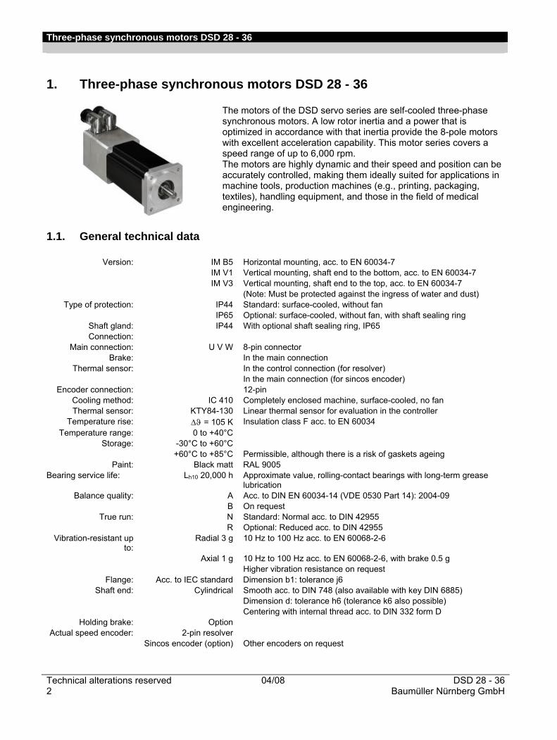
The motors of the DSD servo series are self-cooled three-phase synchronous motors. A low rotor inertia and a power that is optimized in accordance with that inertia provide the 8-pole motors with excellent acceleration capability. This motor series covers a speed range of up to 6,000 rpm. The motors are highly dynamic and their speed and position can be accurately controlled, making them ideally suited for applications in machine tools, production machines (e.g., printing, packaging, textiles), handling equipment, and those in the field of medical engineering.
1.1. General technical data
Version: IM B5 Horizontal mounting, acc. to EN 60034-7 IM V1 Vertical mounting, shaft end to the bottom, acc. to EN 60034-7 IM V3 Vertical mounting, shaft end to the top, acc. to EN 60034-7
(Note: Must be protected against the ingress of water and dust) Type of protection: IP44 Standard: surface-cooled, without fan
IP65 Optional: surface-cooled, without fan, with shaft sealing ring Shaft gland: IP44 With optional shaft sealing ring, IP65 Connection:
Main connection: U V W 8-pin connector Brake: In the main connection
Thermal sensor: In the control connection (for resolver) In the main connection (for sincos encoder)
Encoder connection: 12-pin Cooling method: IC 410 Completely enclosed machine, surface-cooled, no fan Thermal sensor: KTY84-130 Linear thermal sensor for evaluation in the controller
Temperature rise: Δϑ = 105 K Insulation class F acc. to EN 60034 Temperature range: 0 to +40°C
Storage: -30°C to +60°C +60°C to +85°C
Permissible, although there is a risk of gaskets ageing
Paint: Black matt RAL 9005 Bearing service life: Lh10 20,000 h Approximate value, rolling-contact bearings with long-term grease
lubrication Balance quality: A Acc. to DIN EN 60034-14 (VDE 0530 Part 14): 2004-09
B On request True run: N Standard: Normal acc. to DIN 42955
R Optional: Reduced acc. to DIN 42955 Vibration-resistant up
to: Radial 3 g 10 Hz to 100 Hz acc. to EN 60068-2-6
Axial 1 g 10 Hz to 100 Hz acc. to EN 60068-2-6, with brake 0.5 g Higher vibration resistance on request
Flange: Acc. to IEC standard Dimension b1: tolerance j6 Shaft end: Cylindrical Smooth acc. to DIN 748 (also available with key DIN 6885)
Dimension d: tolerance h6 (tolerance k6 also possible) Centering with internal thread acc. to DIN 332 form D
Holding brake: Option Actual speed encoder: 2-pin resolver
Sincos encoder (option) Other encoders on request
Three-phase synchronous motors DSD 28 - 36
DSD 28 - 36 04/08 Technical alterations reservedBaumüller Nürnberg GmbH 3
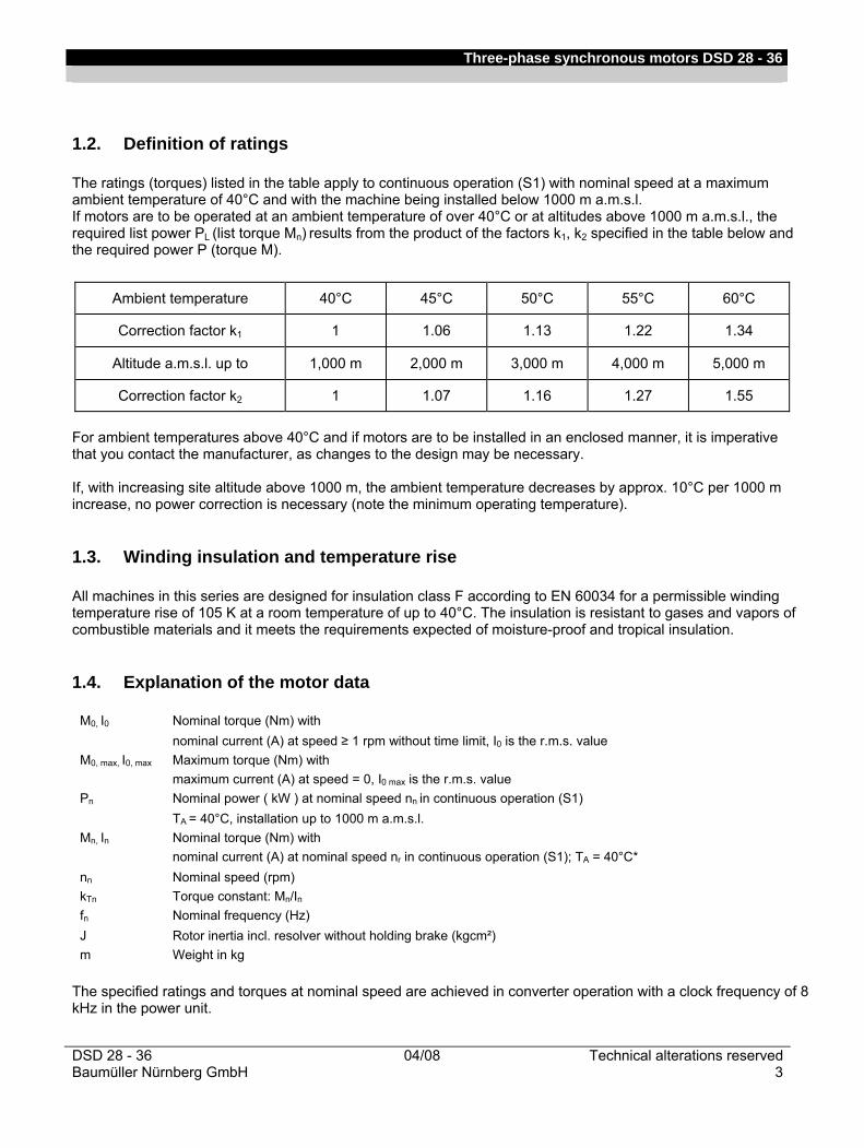
1.2. Definition of ratings The ratings (torques) listed in the table apply to continuous operation (S1) with nominal speed at a maximum ambient temperature of 40°C and with the machine being installed below 1000 m a.m.s.l. If motors are to be operated at an ambient temperature of over 40°C or at altitudes above 1000 m a.m.s.l., the required list power PL (list torque Mn) results from the product of the factors k1, k2 specified in the table below and the required power P (torque M).
Ambient temperature 40°C 45°C 50°C 55°C 60°C
Correction factor k1 1 1.06 1.13 1.22 1.34
Altitude a.m.s.l. up to 1,000 m 2,000 m 3,000 m 4,000 m 5,000 m
Correction factor k2 1 1.07 1.16 1.27 1.55
For ambient temperatures above 40°C and if motors are to be installed in an enclosed manner, it is imperative that you contact the manufacturer, as changes to the design may be necessary. If, with increasing site altitude above 1000 m, the ambient temperature decreases by approx. 10°C per 1000 m increase, no power correction is necessary (note the minimum operating temperature).
1.3. Winding insulation and temperature rise All machines in this series are designed for insulation class F according to EN 60034 for a permissible winding temperature rise of 105 K at a room temperature of up to 40°C. The insulation is resistant to gases and vapors of combustible materials and it meets the requirements expected of moisture-proof and tropical insulation.
1.4. Explanation of the motor data
M0, I0 Nominal torque (Nm) with nominal current (A) at speed ≥ 1 rpm without time limit, I0 is the r.m.s. value M0, max, I0, max Maximum torque (Nm) with maximum current (A) at speed = 0, I0 max is the r.m.s. value Pn Nominal power ( kW ) at nominal speed nn in continuous operation (S1) TA = 40°C, installation up to 1000 m a.m.s.l. Mn, In Nominal torque (Nm) with nominal current (A) at nominal speed nr in continuous operation (S1); TA = 40°C* nn Nominal speed (rpm) kTn Torque constant: Mn/In fn Nominal frequency (Hz) J Rotor inertia incl. resolver without holding brake (kgcm²) m Weight in kg
The specified ratings and torques at nominal speed are achieved in converter operation with a clock frequency of 8 kHz in the power unit.
Three-phase synchronous motors DSD 28 - 36
Technical alterations reserved 04/08 DSD 28 - 364 Baumüller Nürnberg GmbH
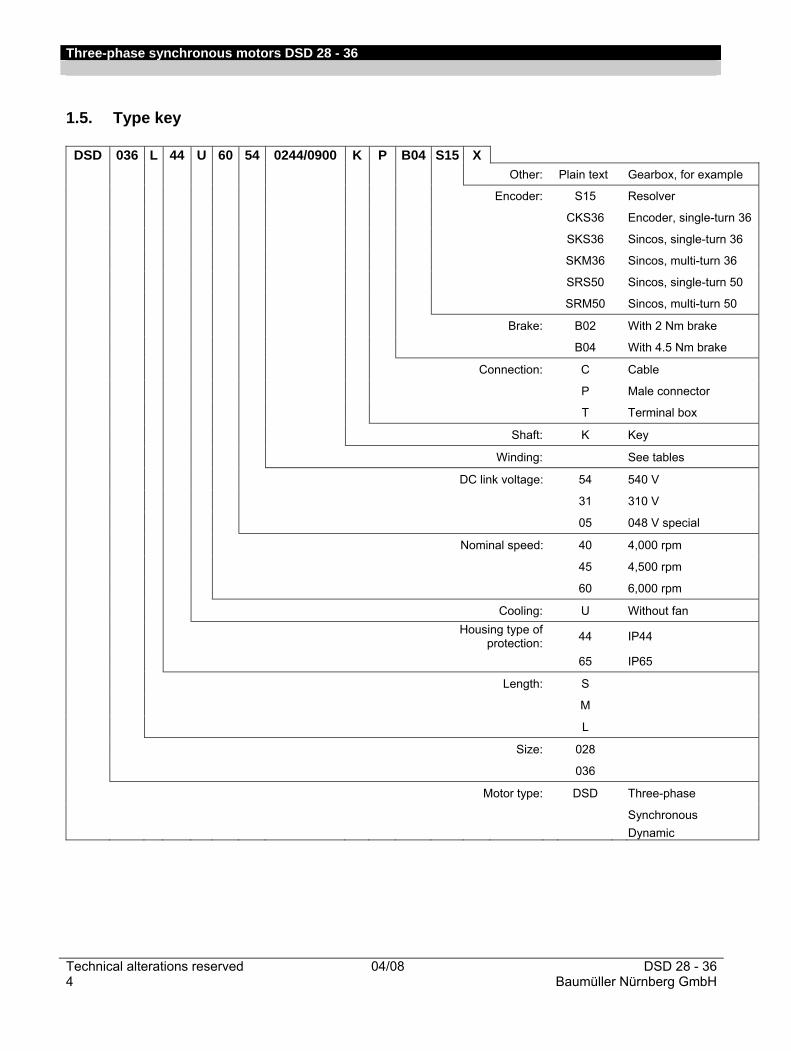
1.5. Type key
DSD 036 L 44 U 60 54 0244/0900 K P B04 S15 X Other: Plain text Gearbox, for example
Encoder: S15 Resolver
CKS36 Encoder, single-turn 36
SKS36 Sincos, single-turn 36
SKM36 Sincos, multi-turn 36
SRS50 Sincos, single-turn 50
SRM50 Sincos, multi-turn 50
Brake: B02 With 2 Nm brake
B04 With 4.5 Nm brake
Connection: C Cable
P Male connector
T Terminal box
Shaft: K Key
Winding: See tables
DC link voltage: 54 540 V
31 310 V
05 048 V special
Nominal speed: 40 4,000 rpm
45 4,500 rpm
60 6,000 rpm
Cooling: U Without fan
Housing type of protection: 44 IP44
65 IP65
Length: S
M
L
Size: 028
036
Motor type: DSD Three-phase
Synchronous Dynamic
Three-phase synchronous motors DSD 28 - 36
DSD 28 - 36 04/08 Technical alterations reservedBaumüller Nürnberg GmbH 5
2. Technical data
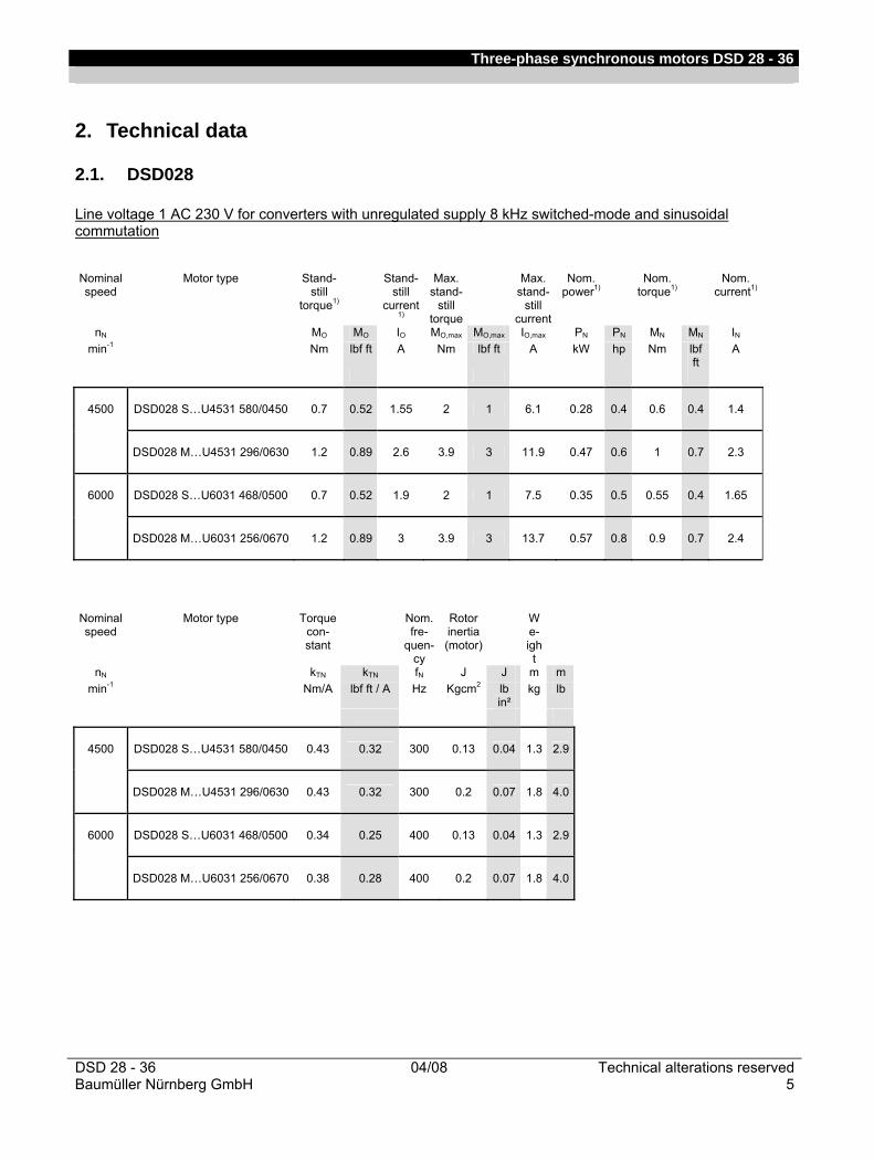
2.1. DSD028 Line voltage 1 AC 230 V for converters with unregulated supply 8 kHz switched-mode and sinusoidal commutation
Nominal speed
Motor type Stand-still
torque1)
Stand-still
current 1)
Max. stand-
still torque
Max. stand-
still current
Nom. power1)
Nom. torque1)
Nom. current1)
nN MO MO IO MO,max MO,max IO,max PN PN MN MN IN min-1 Nm lbf ft A Nm lbf ft A kW hp Nm lbf
ft A
4500 DSD028 S…U4531 580/0450 0.7 0.52 1.55 2 1 6.1 0.28 0.4 0.6 0.4 1.4
DSD028 M…U4531 296/0630 1.2 0.89 2.6 3.9 3 11.9 0.47 0.6 1 0.7 2.3
6000 DSD028 S…U6031 468/0500 0.7 0.52 1.9 2 1 7.5 0.35 0.5 0.55 0.4 1.65
DSD028 M…U6031 256/0670 1.2 0.89 3 3.9 3 13.7 0.57 0.8 0.9 0.7 2.4
Nominal speed
Motor type Torque con-stant
Nom. fre-
quen-cy
Rotor inertia (motor)
We- ight
nN kTN kTN fN J J m m min-1 Nm/A lbf ft / A Hz Kgcm2 lb
in² kg lb
4500 DSD028 S…U4531 580/0450 0.43 0.32 300 0.13 0.04 1.3 2.9
DSD028 M…U4531 296/0630 0.43 0.32 300 0.2 0.07 1.8 4.0
6000 DSD028 S…U6031 468/0500 0.34 0.25 400 0.13 0.04 1.3 2.9
DSD028 M…U6031 256/0670 0.38 0.28 400 0.2 0.07 1.8 4.0
Three-phase synchronous motors DSD 28 - 36
Technical alterations reserved 04/08 DSD 28 - 366 Baumüller Nürnberg GmbH
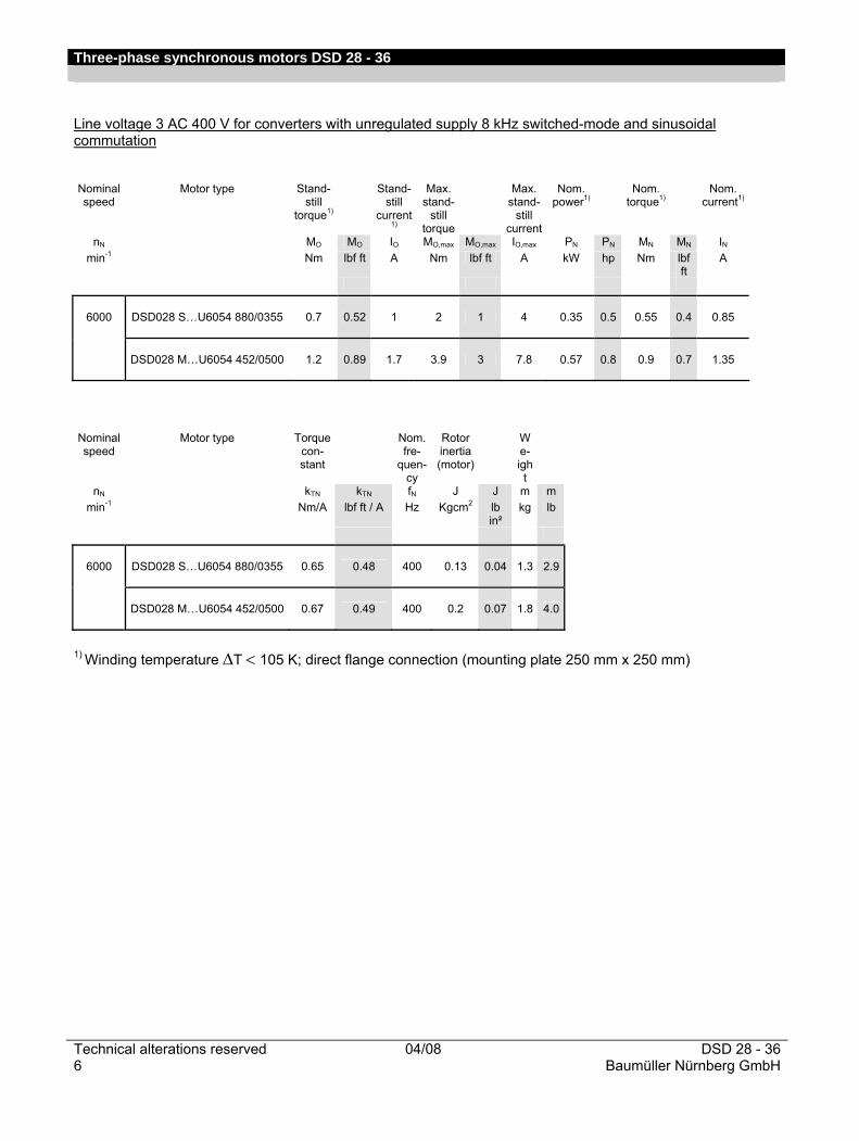
Line voltage 3 AC 400 V for converters with unregulated supply 8 kHz switched-mode and sinusoidal commutation Nominal speed
Motor type Stand-still
torque1)
Stand-still
current 1)
Max. stand-
still torque
Max. stand-
still current
Nom. power1)
Nom. torque1)
Nom. current1)
nN MO MO IO MO,max MO,max IO,max PN PN MN MN IN min-1 Nm lbf ft A Nm lbf ft A kW hp Nm lbf
ft A
6000 DSD028 S…U6054 880/0355 0.7 0.52 1 2 1 4 0.35 0.5 0.55 0.4 0.85
DSD028 M…U6054 452/0500 1.2 0.89 1.7 3.9 3 7.8 0.57 0.8 0.9 0.7 1.35
Nominal speed
Motor type Torque con-stant
Nom. fre-
quen-cy
Rotor inertia (motor)
We- ight
nN kTN kTN fN J J m m min-1 Nm/A lbf ft / A Hz Kgcm2 lb
in² kg lb
6000 DSD028 S…U6054 880/0355 0.65 0.48 400 0.13 0.04 1.3 2.9
DSD028 M…U6054 452/0500 0.67 0.49 400 0.2 0.07 1.8 4.0
1) Winding temperature ΔT < 105 K; direct flange connection (mounting plate 250 mm x 250 mm)

Three-phase synchronous motors DSD 28 - 36
DSD 28 - 36 04/08 Technical alterations reservedBaumüller Nürnberg GmbH 7
DSD028 S 580/0450 DC link voltage UDC = 310 V
0,0
0,5
1,0
1,5
2,0
2,5
0 1000 2000 3000 4000 5000 6000 7000 8000
Drehzahl / speed [U/min]
Dre
hmom
ent /
torq
ue [N
m]
Grenzkennlinie / Kalter Motor torque limit / cold motor 230V (210V) / I,max
Grenzkennlinie / Betriebswarmer Motor torque limit / motor at operation temperature 230V (210V) / I,max
Grenzkennlinie / Betriebswarmer Motor torque limit / motor at operation temperature 230V (210V)-10 % / I,max
Betriebsart / duty type: S3-20%, 1 min
Betriebsart / duty type: S3-40%, 1 min
Betriebsart / duty type: S1
DSD028 S 468/0500 DC link voltage UDC = 310 V
0,0
0,5
1,0
1,5
2,0
2,5
0 2000 4000 6000 8000 10000
Drehzahl / speed [U/min]
Dre
hmom
ent /
torq
ue [N
m]
Grenzkennlinie / Kalter Motor torque limit / cold motor 230V (210V) / I,max
Grenzkennlinie / Betriebswarmer Motor torque limit / motor at operation temperature 230V (210V) / I,max
Grenzkennlinie / Betriebswarmer Motor torque limit / motor at operation temperature 230V (210V)-10 % / I,max
Betriebsart / duty type: S3-20%, 1 min
Betriebsart / duty type: S3-40%, 1 min
Betriebsart / duty type: S1
Three-phase synchronous motors DSD 28 - 36
Technical alterations reserved 04/08 DSD 28 - 368 Baumüller Nürnberg GmbH
0,0
0,5
1,0
1,5
2,0
2,5
3,0
3,5
4,0
4,5
5,0
0 1000 2000 3000 4000 5000 6000 7000 8000
Drehzahl / speed [U/min]
Dre
hmom
ent /
torq
ue [N
m]
Grenzkennlinie / Kalter Motor torque limit / cold motor 230V (210V) / I,max
Grenzkennlinie / Betriebswarmer Motor torque limit / motor at operation temperature 230V (210V) / I,max
Grenzkennlinie / Betriebswarmer Motor torque limit / motor at operation temperature 230V (210V)-10 % / I,max
Betriebsart / duty type: S3-20%, 1 min
Betriebsart / duty type: S3-40%, 1 min
Betriebsart / duty type: S1
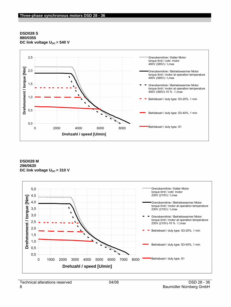
DSD028 S 880/0355 DC link voltage UDC = 540 V
0,0
0,5
1,0
1,5
2,0
2,5
0 2000 4000 6000 8000
Drehzahl / speed [U/min]
Dre
hmom
ent /
torq
ue [N
m]
Grenzkennlinie / Kalter Motor torque limit / cold motor 400V (365V) / I,max
Grenzkennlinie / Betriebswarmer Motor torque limit / motor at operation temperature 400V (365V) / I,max
Grenzkennlinie / Betriebswarmer Motor torque limit / motor at operation temperature 400V (365V)-10 % / I,max
Betriebsart / duty type: S3-20%, 1 min
Betriebsart / duty type: S3-40%, 1 min
Betriebsart / duty type: S1
DSD028 M 296/0630 DC link voltage UDC = 310 V

Three-phase synchronous motors DSD 28 - 36
DSD 28 - 36 04/08 Technical alterations reservedBaumüller Nürnberg GmbH 9
DSD028 M 256/0670 DC link voltage UDC = 310 V
0,0
0,5
1,0
1,5
2,0
2,5
3,0
3,5
4,0
4,5
5,0
0 1000 2000 3000 4000 5000 6000 7000 8000 9000
Drehzahl / speed [U/min]
Dre
hmom
ent /
torq
ue [N
m]
Grenzkennlinie / Kalter Motor torque limit / cold motor 230V (210V) / I,max
Grenzkennlinie / Betriebswarmer Motor torque limit / motor at operation temperature 230V (210V) / I,max
Grenzkennlinie / Betriebswarmer Motor torque limit / motor at operation temperature 230V (210V)-10 % / I,max
Betriebsart / duty type: S3-20%, 1 min
Betriebsart / duty type: S3-40%, 1 min
Betriebsart / duty type: S1
DSD028 M 452/0500 DC link voltage UDC = 540 V
0,0
0,5
1,0
1,5
2,0
2,5
3,0
3,5
4,0
4,5
5,0
0 1000 2000 3000 4000 5000 6000 7000 8000 9000
Drehzahl / speed [U/min]
Dre
hmom
ent /
torq
ue [N
m]
Grenzkennlinie / Kalter Motor torque limit / cold motor 400V (365V) / I,max
Grenzkennlinie / Betriebswarmer Motor torque limit / motor at operation temperature 400V (365V) / I,max
Grenzkennlinie / Betriebswarmer Motor torque limit / motor at operation temperature 400V (365V)-10 % / I,max
Betriebsart / duty type: S3-20%, 1 min
Betriebsart / duty type: S3-40%, 1 min
Betriebsart / duty type: S1
Three-phase synchronous motors DSD 28 - 36
Technical alterations reserved 04/08 DSD 28 - 3610 Baumüller Nürnberg GmbH
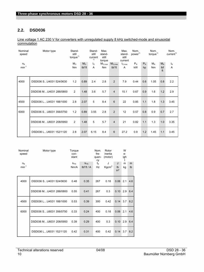
2.2. DSD036 Line voltage 1 AC 230 V for converters with unregulated supply 8 kHz switched-mode and sinusoidal commutation Nominal speed
Motor type Stand-still
torque1)
Stand-still
current 1)
Max. stand-
still torque
Max. stand-
still current
Nom. power1)
Nom. torque1)
Nom. current1)
nN MO MO IO MO,max MO,max IO,max PN PN MN MN IN min-1 Nm lbf ft A Nm lbf ft A kW hp Nm lbf
ft A
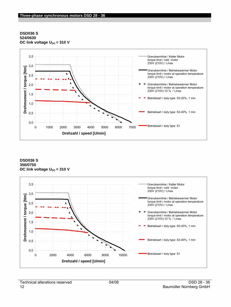
4000 DSD036 S...U4031 524/0630 1.2 0.89 2.4 2.8 2 7.9 0.44 0.6 1.05 0.8 2.2
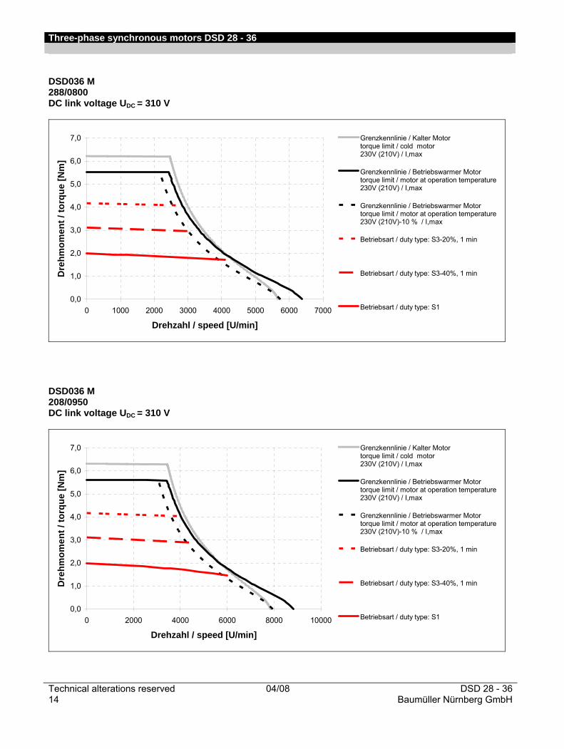
DSD036 M…U4031 288/0800 2 1.48 3.6 5.7 4 15.1 0.67 0.9 1.6 1.2 2.9
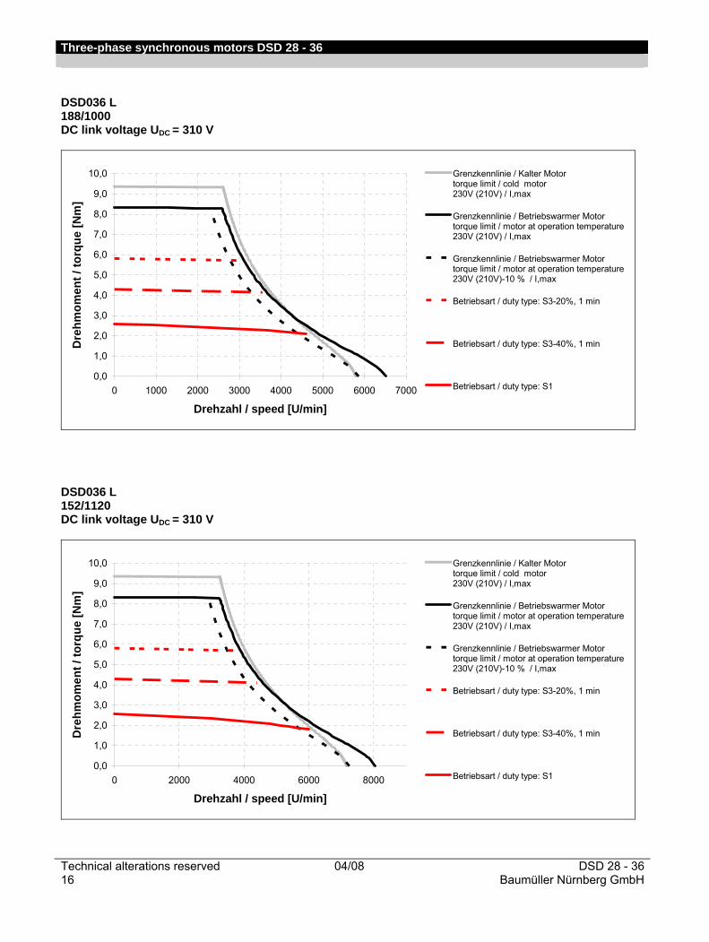
4500 DSD036 L…U4531 188/1000 2.8 2.07 5 8.4 6 22 0.85 1.1 1.8 1.3 3.45
6000 DSD036 S…U6031 356/0750 1.2 0.89 3.55 2.8 2 12 0.57 0.8 0.9 0.7 2.7
DSD036 M…U6031 208/0950 2 1.48 5 5.7 4 21 0.82 1.1 1.3 1.0 3.35
DSD036 L...U6031 152/1120 2.8 2.07 6.15 8.4 6 27.2 0.9 1.2 1.45 1.1 3.45
Nominal speed
Motor type Torque con-stant
Nom. fre-
quen-cy
Rotor inertia (motor)
We- ight
nN kTN kTN fN J J m m min-1 Nm/A lbf ft / A Hz Kgcm2 lb
in² kg lb
4000 DSD036 S...U4031 524/0630 0.48 0.35 267 0.18 0.06 2.1 4.6
DSD036 M…U4031 288/0800 0.55 0.41 267 0.3 0.10 2.9 6.4
4500 DSD036 L…U4531 188/1000 0.53 0.39 300 0.42 0.14 3.7 8.2
6000 DSD036 S…U6031 356/0750 0.33 0.24 400 0.18 0.06 2.1 4.6
DSD036 M…U6031 208/0950 0.39 0.29 400 0.3 0.10 2.9 6.4
DSD036 L...U6031 152/1120 0.42 0.31 400 0.42 0.14 3.7 8.2
Three-phase synchronous motors DSD 28 - 36
DSD 28 - 36 04/08 Technical alterations reservedBaumüller Nürnberg GmbH 11
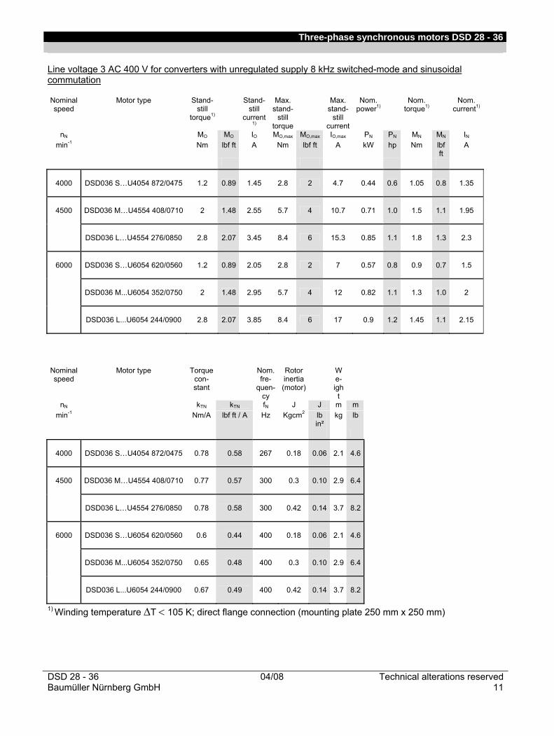
Line voltage 3 AC 400 V for converters with unregulated supply 8 kHz switched-mode and sinusoidal commutation Nominal speed
Motor type Stand-still
torque1)
Stand-still
current 1)
Max. stand-
still torque
Max. stand-
still current
Nom. power1)
Nom. torque1)
Nom. current1)
nN MO MO IO MO,max MO,max IO,max PN PN MN MN IN min-1 Nm lbf ft A Nm lbf ft A kW hp Nm lbf
ft A
4000 DSD036 S…U4054 872/0475 1.2 0.89 1.45 2.8 2 4.7 0.44 0.6 1.05 0.8 1.35
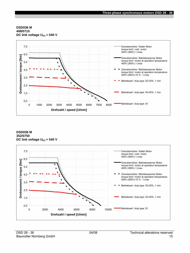
4500 DSD036 M…U4554 408/0710 2 1.48 2.55 5.7 4 10.7 0.71 1.0 1.5 1.1 1.95
DSD036 L…U4554 276/0850 2.8 2.07 3.45 8.4 6 15.3 0.85 1.1 1.8 1.3 2.3
6000 DSD036 S…U6054 620/0560 1.2 0.89 2.05 2.8 2 7 0.57 0.8 0.9 0.7 1.5
DSD036 M...U6054 352/0750 2 1.48 2.95 5.7 4 12 0.82 1.1 1.3 1.0 2
DSD036 L...U6054 244/0900 2.8 2.07 3.85 8.4 6 17 0.9 1.2 1.45 1.1 2.15
Nominal speed
Motor type Torque con-stant
Nom. fre-
quen-cy
Rotor inertia (motor)
We- ight
nN kTN kTN fN J J m m min-1 Nm/A lbf ft / A Hz Kgcm2 lb
in² kg lb
4000 DSD036 S…U4054 872/0475 0.78 0.58 267 0.18 0.06 2.1 4.6
4500 DSD036 M…U4554 408/0710 0.77 0.57 300 0.3 0.10 2.9 6.4
DSD036 L…U4554 276/0850 0.78 0.58 300 0.42 0.14 3.7 8.2
6000 DSD036 S…U6054 620/0560 0.6 0.44 400 0.18 0.06 2.1 4.6
DSD036 M...U6054 352/0750 0.65 0.48 400 0.3 0.10 2.9 6.4
DSD036 L...U6054 244/0900 0.67 0.49 400 0.42 0.14 3.7 8.2
1) Winding temperature ΔT < 105 K; direct flange connection (mounting plate 250 mm x 250 mm)
Three-phase synchronous motors DSD 28 - 36
Technical alterations reserved 04/08 DSD 28 - 3612 Baumüller Nürnberg GmbH
DSD036 S 524/0630 DC link voltage UDC = 310 V
0,0
0,5
1,0
1,5
2,0
2,5
3,0
3,5
0 1000 2000 3000 4000 5000 6000 7000
Drehzahl / speed [U/min]
Dre
hmom
ent /
torq
ue [N
m]
Grenzkennlinie / Kalter Motor torque limit / cold motor 230V (210V) / I,max
Grenzkennlinie / Betriebswarmer Motor torque limit / motor at operation temperature 230V (210V) / I,max
Grenzkennlinie / Betriebswarmer Motor torque limit / motor at operation temperature 230V (210V)-10 % / I,max
Betriebsart / duty type: S3-20%, 1 min
Betriebsart / duty type: S3-40%, 1 min
Betriebsart / duty type: S1
DSD036 S 356/0750 DC link voltage UDC = 310 V
0,0
0,5
1,0
1,5
2,0
2,5
3,0
3,5
0 2000 4000 6000 8000 10000
Drehzahl / speed [U/min]
Dre
hmom
ent /
torq
ue [N
m]
Grenzkennlinie / Kalter Motor torque limit / cold motor 230V (210V) / I,max
Grenzkennlinie / Betriebswarmer Motor torque limit / motor at operation temperature 230V (210V) / I,max
Grenzkennlinie / Betriebswarmer Motor torque limit / motor at operation temperature 230V (210V)-10 % / I,max
Betriebsart / duty type: S3-20%, 1 min
Betriebsart / duty type: S3-40%, 1 min
Betriebsart / duty type: S1

Three-phase synchronous motors DSD 28 - 36
DSD 28 - 36 04/08 Technical alterations reservedBaumüller Nürnberg GmbH 13
DSD036 S 872/0475 DC link voltage UDC = 540 V
0,0
0,5
1,0
1,5
2,0
2,5
3,0
3,5
0 1000 2000 3000 4000 5000 6000 7000 8000
Drehzahl / speed [U/min]
Dre
hmom
ent /
torq
ue [N
m]
Grenzkennlinie / Kalter Motor torque limit / cold motor 400V (365V) / I,max
Grenzkennlinie / Betriebswarmer Motor torque limit / motor at operation temperature 400V (365V) / I,max
Grenzkennlinie / Betriebswarmer Motor torque limit / motor at operation temperature 400V (365V)-10 % / I,max
Betriebsart / duty type: S3-20%, 1 min
Betriebsart / duty type: S3-40%, 1 min
Betriebsart / duty type: S1
DSD036 S 620/0560 DC link voltage UDC = 540 V
0,0
0,5
1,0
1,5
2,0
2,5
3,0
3,5
0 2000 4000 6000 8000 10000
Drehzahl / speed [U/min]
Dre
hmom
ent /
torq
ue [N
m]
Grenzkennlinie / Kalter Motor torque limit / cold motor 400V (365V) / I,max
Grenzkennlinie / Betriebswarmer Motor torque limit / motor at operation temperature 400V (365V) / I,max
Grenzkennlinie / Betriebswarmer Motor torque limit / motor at operation temperature 400V (365V)-10 % / I,max
Betriebsart / duty type: S3-20%, 1 min
Betriebsart / duty type: S3-40%, 1 min
Betriebsart / duty type: S1
Three-phase synchronous motors DSD 28 - 36
Technical alterations reserved 04/08 DSD 28 - 3614 Baumüller Nürnberg GmbH
DSD036 M 288/0800 DC link voltage UDC = 310 V
0,0
1,0
2,0
3,0
4,0
5,0
6,0
7,0
0 1000 2000 3000 4000 5000 6000 7000
Drehzahl / speed [U/min]
Dre
hmom
ent /
torq
ue [N
m]
Grenzkennlinie / Kalter Motor torque limit / cold motor 230V (210V) / I,max
Grenzkennlinie / Betriebswarmer Motor torque limit / motor at operation temperature 230V (210V) / I,max
Grenzkennlinie / Betriebswarmer Motor torque limit / motor at operation temperature 230V (210V)-10 % / I,max
Betriebsart / duty type: S3-20%, 1 min
Betriebsart / duty type: S3-40%, 1 min
Betriebsart / duty type: S1
DSD036 M 208/0950 DC link voltage UDC = 310 V
0,0
1,0
2,0
3,0
4,0
5,0
6,0
7,0
0 2000 4000 6000 8000 10000
Drehzahl / speed [U/min]
Dre
hmom
ent /
torq
ue [N
m]
Grenzkennlinie / Kalter Motor torque limit / cold motor 230V (210V) / I,max
Grenzkennlinie / Betriebswarmer Motor torque limit / motor at operation temperature 230V (210V) / I,max
Grenzkennlinie / Betriebswarmer Motor torque limit / motor at operation temperature 230V (210V)-10 % / I,max
Betriebsart / duty type: S3-20%, 1 min
Betriebsart / duty type: S3-40%, 1 min
Betriebsart / duty type: S1
Three-phase synchronous motors DSD 28 - 36
DSD 28 - 36 04/08 Technical alterations reservedBaumüller Nürnberg GmbH 15
DSD036 M 408/0710 DC link voltage UDC = 540 V
0,0
1,0
2,0
3,0
4,0
5,0
6,0
7,0
0 1000 2000 3000 4000 5000 6000 7000 8000
Drehzahl / speed [U/min]
Dre
hmom
ent /
torq
ue [N
m]
Grenzkennlinie / Kalter Motor torque limit / cold motor 400V (365V) / I,max
Grenzkennlinie / Betriebswarmer Motor torque limit / motor at operation temperature 400V (365V) / I,max
Grenzkennlinie / Betriebswarmer Motor torque limit / motor at operation temperature 400V (365V)-10 % / I,max
Betriebsart / duty type: S3-20%, 1 min
Betriebsart / duty type: S3-40%, 1 min
Betriebsart / duty type: S1
DSD036 M 352/0750 DC link voltage UDC = 540 V
0,0
1,0
2,0
3,0
4,0
5,0
6,0
7,0
0 2000 4000 6000 8000 10000
Drehzahl / speed [U/min]
Dre
hmom
ent /
torq
ue [N
m]
Grenzkennlinie / Kalter Motor torque limit / cold motor 400V (365V) / I,max
Grenzkennlinie / Betriebswarmer Motor torque limit / motor at operation temperature 400V (365V) / I,max
Grenzkennlinie / Betriebswarmer Motor torque limit / motor at operation temperature 400V (365V)-10 % / I,max
Betriebsart / duty type: S3-20%, 1 min
Betriebsart / duty type: S3-40%, 1 min
Betriebsart / duty type: S1
Three-phase synchronous motors DSD 28 - 36
Technical alterations reserved 04/08 DSD 28 - 3616 Baumüller Nürnberg GmbH
DSD036 L 188/1000 DC link voltage UDC = 310 V
0,0
1,0
2,0
3,0
4,0
5,0
6,0
7,0
8,0
9,0
10,0
0 1000 2000 3000 4000 5000 6000 7000
Drehzahl / speed [U/min]
Dre
hmom
ent /
torq
ue [N
m]
Grenzkennlinie / Kalter Motor torque limit / cold motor 230V (210V) / I,max
Grenzkennlinie / Betriebswarmer Motor torque limit / motor at operation temperature 230V (210V) / I,max
Grenzkennlinie / Betriebswarmer Motor torque limit / motor at operation temperature 230V (210V)-10 % / I,max
Betriebsart / duty type: S3-20%, 1 min
Betriebsart / duty type: S3-40%, 1 min
Betriebsart / duty type: S1
DSD036 L 152/1120 DC link voltage UDC = 310 V
0,0
1,0
2,0
3,0
4,0
5,0
6,0
7,0
8,0
9,0
10,0
0 2000 4000 6000 8000
Drehzahl / speed [U/min]
Dre
hmom
ent /
torq
ue [N
m]
Grenzkennlinie / Kalter Motor torque limit / cold motor 230V (210V) / I,max
Grenzkennlinie / Betriebswarmer Motor torque limit / motor at operation temperature 230V (210V) / I,max
Grenzkennlinie / Betriebswarmer Motor torque limit / motor at operation temperature 230V (210V)-10 % / I,max
Betriebsart / duty type: S3-20%, 1 min
Betriebsart / duty type: S3-40%, 1 min
Betriebsart / duty type: S1
Three-phase synchronous motors DSD 28 - 36
DSD 28 - 36 04/08 Technical alterations reservedBaumüller Nürnberg GmbH 17
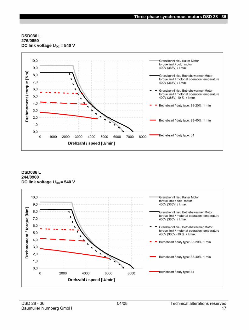
DSD036 L 276/0850 DC link voltage UDC = 540 V
0,0
1,0
2,0
3,0
4,0
5,0
6,0
7,0
8,0
9,0
10,0
0 1000 2000 3000 4000 5000 6000 7000 8000
Drehzahl / speed [U/min]
Dre
hmom
ent /
torq
ue [N
m]
Grenzkennlinie / Kalter Motor torque limit / cold motor 400V (365V) / I,max
Grenzkennlinie / Betriebswarmer Motor torque limit / motor at operation temperature 400V (365V) / I,max
Grenzkennlinie / Betriebswarmer Motor torque limit / motor at operation temperature 400V (365V)-10 % / I,max
Betriebsart / duty type: S3-20%, 1 min
Betriebsart / duty type: S3-40%, 1 min
Betriebsart / duty type: S1
DSD036 L 244/0900 DC link voltage UDC = 540 V
0,0
1,0
2,0
3,0
4,0
5,0
6,0
7,0
8,0
9,0
10,0
0 2000 4000 6000 8000
Drehzahl / speed [U/min]
Dre
hmom
ent /
torq
ue [N
m]
Grenzkennlinie / Kalter Motor torque limit / cold motor 400V (365V) / I,max
Grenzkennlinie / Betriebswarmer Motor torque limit / motor at operation temperature 400V (365V) / I,max
Grenzkennlinie / Betriebswarmer Motor torque limit / motor at operation temperature 400V (365V)-10 % / I,max
Betriebsart / duty type: S3-20%, 1 min
Betriebsart / duty type: S3-40%, 1 min
Betriebsart / duty type: S1
Three-phase synchronous motors DSD 28 - 36
Technical alterations reserved 04/08 DSD 28 - 3618 Baumüller Nürnberg GmbH
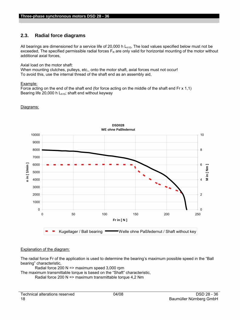
2.3. Radial force diagrams All bearings are dimensioned for a service life of 20,000 h Lh10, The load values specified below must not be exceeded, The specified permissible radial forces FR are only valid for horizontal mounting of the motor without additional axial forces, Axial load on the motor shaft: When mounting clutches, pulleys, etc,, onto the motor shaft, axial forces must not occur! To avoid this, use the internal thread of the shaft end as an assembly aid, Example: Force acting on the end of the shaft end (for force acting on the middle of the shaft end Fr x 1,1) Bearing life 20,000 h Lh10; shaft end without keyway Diagrams:
DSD028WE ohne Paßfedernut
0
1000
2000
3000
4000
5000
6000
7000
8000
9000
10000
0 50 100 150 200 250
Fr in [ N ]
n in
[ 1/
min
]
0
2
4
6
8
10
M in
[ N
m ]
Kugellager / Ball bearing Welle ohne Paßfedernut / Shaft without key
Explanation of the diagram: The radial force Fr of the application is used to determine the bearing’s maximum possible speed in the “Ball bearing” characteristic, Radial force 200 N => maximum speed 3,000 rpm
The maximum transmittable torque is based on the “Shaft” characteristic, Radial force 200 N => maximum transmittable torque 4,2 Nm
Three-phase synchronous motors DSD 28 - 36
DSD 28 - 36 04/08 Technical alterations reservedBaumüller Nürnberg GmbH 19
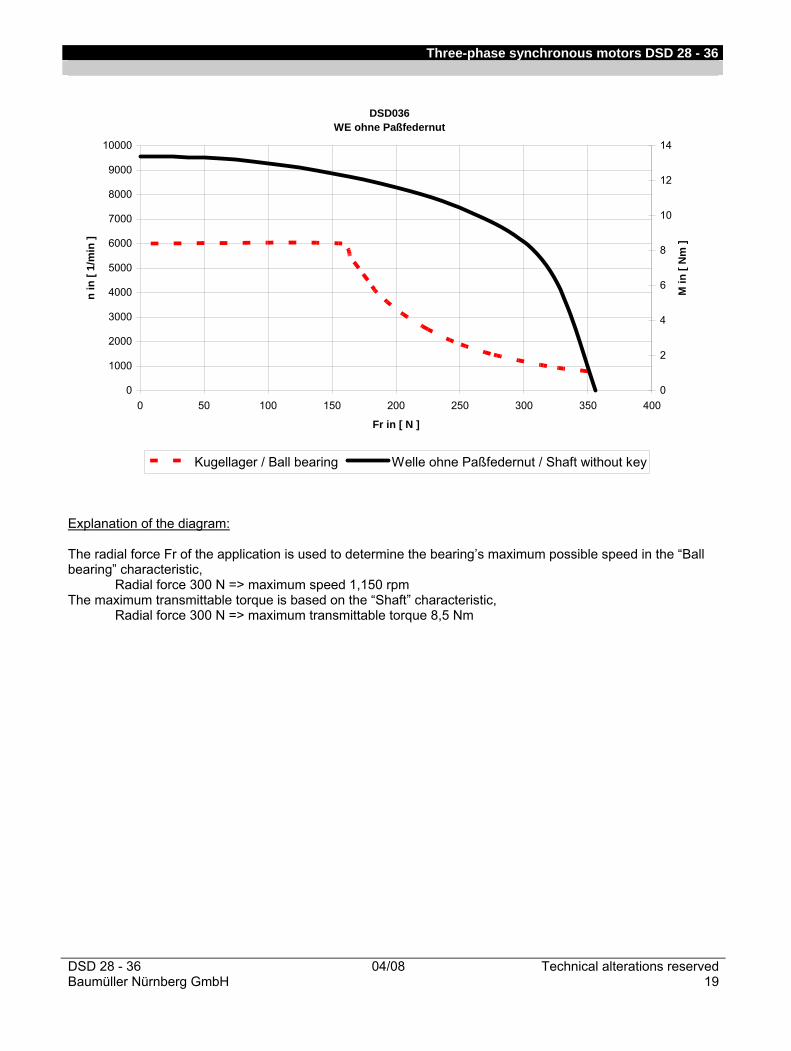
DSD036WE ohne Paßfedernut
0
1000
2000
3000
4000
5000
6000
7000
8000
9000
10000
0 50 100 150 200 250 300 350 400
Fr in [ N ]
n in
[ 1/
min
]
0
2
4
6
8
10
12
14
M in
[ N
m ]
Kugellager / Ball bearing Welle ohne Paßfedernut / Shaft without key
Explanation of the diagram: The radial force Fr of the application is used to determine the bearing’s maximum possible speed in the “Ball bearing” characteristic, Radial force 300 N => maximum speed 1,150 rpm The maximum transmittable torque is based on the “Shaft” characteristic, Radial force 300 N => maximum transmittable torque 8,5 Nm
Three-phase synchronous motors DSD 28 - 36
Technical alterations reserved 04/08 DSD 28 - 3620 Baumüller Nürnberg GmbH
3. Motor components (options)
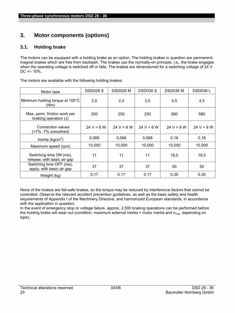
3.1. Holding brake The motors can be equipped with a holding brake as an option, The holding brakes in question are permanent-magnet brakes which are free from backlash, The brakes use the normally-on principle, i,e,, the brake engages when the operating voltage is switched off or fails, The brakes are dimensioned for a switching voltage of 24 V DC +/- 10%, The motors are available with the following holding brakes:
Motor type DSD028 S DSD028 M DSD036 S DSD036 M DSD036 L
Minimum holding torque at 100°C (Nm)
2,0 2,0 2,0 4,5 4,5
Max, perm, friction work per braking operation (J)
250 250 250 580 580
Connection values (+7% -7% smoothed)
24 V = 8 W 24 V = 8 W 24 V = 8 W 24 V = 9 W 24 V = 9 W
Inertia (kgcm2) 0,068 0,068 0,068 0,18 0,18
Maximum speed (rpm) 10,000 10,000 10,000 10,000 10,000
Switching time ON (ms), release; with basic air gap
11 11 11 18,5 18,5
Switching time OFF (ms), apply; with basic air gap 37 37 37 50 50
Weight (kg) 0,17 0,17 0,17 0,35 0,35 None of the brakes are fail-safe brakes, so the torque may be reduced by interference factors that cannot be controlled, Observe the relevant accident prevention guidelines, as well as the basic safety and health requirements of Appendix I of the Machinery Directive, and harmonized European standards, in accordance with the application in question, In the event of emergency stop or voltage failure, approx, 2,500 braking operations can be performed before the holding brake will wear out (condition: maximum external inertia = motor inertia and nmax, depending on type),
Three-phase synchronous motors DSD 28 - 36
DSD 28 - 36 04/08 Technical alterations reservedBaumüller Nürnberg GmbH 21
3.2. Encoder
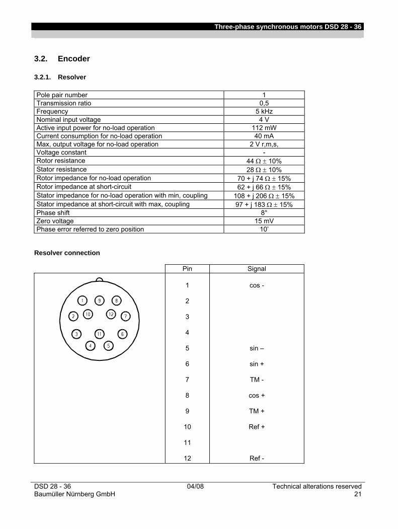
3.2.1. Resolver Pole pair number 1 Transmission ratio 0,5 Frequency 5 kHz Nominal input voltage 4 V Active input power for no-load operation 112 mW Current consumption for no-load operation 40 mA Max, output voltage for no-load operation 2 V r,m,s, Voltage constant - Rotor resistance 44 Ω ± 10% Stator resistance 28 Ω ± 10% Rotor impedance for no-load operation 70 + j 74 Ω ± 15% Rotor impedance at short-circuit 62 + j 66 Ω ± 15% Stator impedance for no-load operation with min, coupling 108 + j 206 Ω ± 15% Stator impedance at short-circuit with max, coupling 97 + j 183 Ω ± 15% Phase shift 8° Zero voltage 15 mV Phase error referred to zero position 10’
Resolver connection
Pin Signal
1
2
3
4
5
6
7
8
9
10
11
12
cos -
sin –
sin +
TM -
cos +
TM +
Ref +
Ref -
Three-phase synchronous motors DSD 28 - 36
Technical alterations reserved 04/08 DSD 28 - 3622 Baumüller Nürnberg GmbH
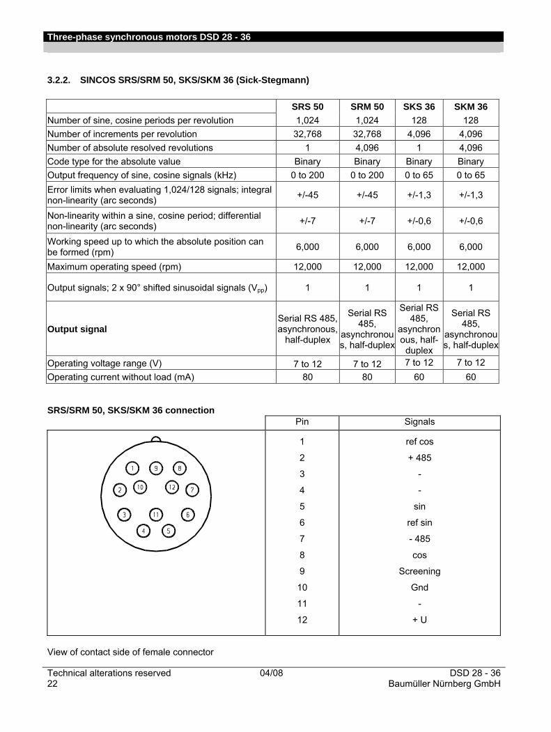
3.2.2. SINCOS SRS/SRM 50, SKS/SKM 36 (Sick-Stegmann)
SRS/SRM 50, SKS/SKM 36 connection
Pin Signals
1
2
3
4
5
6
7
8
9
10
11
12
ref cos
+ 485
-
-
sin
ref sin
- 485
cos
Screening
Gnd
-
+ U
View of contact side of female connector
SRS 50 SRM 50 SKS 36 SKM 36 Number of sine, cosine periods per revolution 1,024 1,024 128 128 Number of increments per revolution 32,768 32,768 4,096 4,096 Number of absolute resolved revolutions 1 4,096 1 4,096 Code type for the absolute value Binary Binary Binary Binary Output frequency of sine, cosine signals (kHz) 0 to 200 0 to 200 0 to 65 0 to 65 Error limits when evaluating 1,024/128 signals; integral non-linearity (arc seconds) +/-45 +/-45 +/-1,3 +/-1,3
Non-linearity within a sine, cosine period; differential non-linearity (arc seconds) +/-7 +/-7 +/-0,6 +/-0,6
Working speed up to which the absolute position can be formed (rpm) 6,000 6,000 6,000 6,000
Maximum operating speed (rpm) 12,000 12,000 12,000 12,000
Output signals; 2 x 90° shifted sinusoidal signals (Vpp) 1 1 1 1
Output signal Serial RS 485,asynchronous,
half-duplex
Serial RS 485,
asynchronous, half-duplex
Serial RS 485,
asynchronous, half-
duplex
Serial RS 485,
asynchronous, half-duplex
Operating voltage range (V) 7 to 12 7 to 12 7 to 12 7 to 12 Operating current without load (mA) 80 80 60 60
Three-phase synchronous motors DSD 28 - 36
DSD 28 - 36 04/08 Technical alterations reservedBaumüller Nürnberg GmbH 23
3.3. Encoder cables General A fully preassembled encoder cable is used for all encoder systems, The connection on the motor side takes the form of a 12-pin round signal connector in the case of a resolver, SKS/SKM36, and SRS/SRM50, The connection on the controller side takes the form of a 15-pin SUB-D connector, The encoder cables are available in 'trailing' or 'non-trailing' versions, The trailing cable is suitable for mobile use in trailing chains, for example, In contrast to the 'non-trailing' cable, which has a PVC sheath, the cable sheath for the trailing version consists of tougher PU for use in environments containing acids and bases (coolants), Cables can be supplied cut to lengths of complete meters up to a maximum of 10 m, If lengths in excess of 10 m are required, cables can be supplied cut at 5 m intervals (10 m, 15 m, etc,),
3.3.1. Technical data 1, Technical description – Non-trailing
• LiYCY, 5x (2 x 0,14 mm²) + 2 x 0,5 mm² stranded copper, twisted pair
• PVC sheath, gray
• 1st end: 12-pin round signal connector with 12 female contacts
• 2nd end: 15-pin SUB-D connector with male contacts and locking screws 4-40UNC
• Baumüller labeling, black
• Outer diameter 9,0 mm (+/- 0,3 mm)
• Bending radius: r ≥ 60 mm (fixed installation), r ≥ 135 mm (flexible use)
• Nominal voltage: 250 VAC 2, Technical description – Trailing
• Li12YC11Y, 5x (2 x 0,14 mm²) + 2 x 0,5 mm² stranded copper, twisted pair
• PU sheath, black
• 1st end: 12-pin round signal connector with 12 female contacts
• 2nd end: 15-pin SUB-D connector with male contacts and locking screws 4-40UNC
• Baumüller labeling, white
• Outer diameter 9,0 mm (+/- 0,3 mm)
• Bending radius: r ≥ 70 mm (fixed installation), r ≥ 100 mm (flexible use)
• Nominal voltage: 300 VAC
Three-phase synchronous motors DSD 28 - 36
Technical alterations reserved 04/08 DSD 28 - 3624 Baumüller Nürnberg GmbH
3.3.2. Application notes • Operating temperature Trailing Non-trailing Limit temperature At the surface At the surface
No/few movements -40°C to +80°C -30°C to +80°C
Continuous movements -30°C to +80°C -5°C to +70°C • Cable laying at the motor The cables must not touch the motor surface,
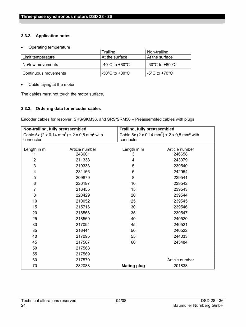
3.3.3. Ordering data for encoder cables Encoder cables for resolver, SKS/SKM36, and SRS/SRM50 – Preassembled cables with plugs Non-trailing, fully preassembled Trailing, fully preassembled Cable 5x (2 x 0,14 mm2) + 2 x 0,5 mm² with connector
Cable 5x (2 x 0,14 mm2) + 2 x 0,5 mm² with connector
Length in m Article number Length in m Article number
1 243601 3 246658 2 211338 4 243379 3 219333 5 239540 4 231166 6 242954 5 209879 8 239541 6 220197 10 239542 7 216455 15 239543 8 220429 20 239544 10 210052 25 239545 15 215716 30 239546 20 218568 35 239547 25 218569 40 240520 30 217094 45 240521 35 216444 50 240522 40 217095 55 244033 45 217567 60 245484 50 217568 55 217569 60 217570 Article number 70 232088 Mating plug 201833
Three-phase synchronous motors DSD 28 - 36
DSD 28 - 36 04/08 Technical alterations reservedBaumüller Nürnberg GmbH 25
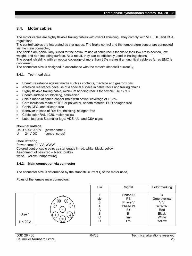
3.4. Motor cables The motor cables are highly flexible trailing cables with overall shielding, They comply with VDE, UL, and CSA regulations, The control cables are integrated as star quads, The brake control and the temperature sensor are connected via the main connector, The cables are particularly suited for the optimum use of cable racks thanks to their low cross-section, low weight, and non-impeding surface, As a result, they can be efficiently used in trailing chains, The overall shielding with an optical coverage of more than 85% makes it an uncritical cable as far as EMC is concerned, The connector size is designed in accordance with the motor's standstill current I0,
3.4.1. Technical data • Sheath resistance against media such as coolants, machine and gearbox oils • Abrasion resistance because of a special surface in cable racks and trailing chains • Highly flexible trailing cable, minimum bending radius for flexible use 12 x D • Sheath surface not blocking, satin-finish • Shield made of tinned copper braid with optical coverage of ≥ 85% • Core insulation made of TPE or polyester, sheath material PUR halogen-free • Cable CFC- and silicone-free • Behavior in case of fire: fire-inhibiting, halogen-free • Cable color RAL 1028, melon yellow • Label features Baumüller logo, VDE, UL, and CSA signs Nominal voltage Uo/U 600/1000 V (power cores) U 24 V DC (control cores) Core lettering Power cores U, VV, WWW Colored control cable pairs as star quads in red, white, black, yellow Assignment of pairs red – black (brake), white – yellow (temperature)
3.4.2. Main connection via connector The connector size is determined by the standstill current I0 of the motor used, Poles of the female main connectors:
Pin Signal Color/marking
Size 1
I0 < 20 A
A
B C
D
3
41
1
3 4 A B C D
Phase U PE
Phase V Phase W
B+ B-
Tm+ Tm-
U Green/yellow
V V W W W
Red Black White Yellow

Three-phase synchronous motors DSD 28 - 36
Technical alterations reserved 04/08 DSD 28 - 3626 Baumüller Nürnberg GmbH
Cable cross-section Nominal
current [A]1)
Connector 540 V size
Cable diameter [mm]
4 ×1,5 mm2 4 × 0,75 mm2 15 1 11,7 – 12,3 1) Current carrying capacity acc, to Table 5 laying type C or E
(VDE 0113/EN 60204 Part 1 issue 1997) Ambient temperature 40°C
For the laying of the cables, the current carrying capacity acc, to Table 5 laying type C or E (VDE 0113/EN 60204 Part 1 issue 1997) and an ambient temperature of 40°C must be considered,
3.4.3. Application notes Operating temperature The cables can be operated within a temperature range from -20°C to +80°C, Cable laying at the motor The cables must not touch the motor surface, Smallest permissible bending radii 12 times outer cable diameter, Smaller bending radii are possible with reduced service life, Maximum cable lengths In the case of converters with a DC link voltage > 500 V, the cables between the converter and the motor must not be longer than 20 meters, For longer cables, additional measures (e,g,, motor filters) must be put in place, The maximum permissible terminal voltage is 1,000 V,
3.4.4. Ordering data for main connection cables
Nominal current: 15 A Cable 4 x 1,5 mm² + 4 x 0,75 mm² With connector size 1 Length in m Article number
5 324781 7 324782 10 324783 15 324784 20 324785 25 324786 30 324787 35 324788 40 324789 50 324790 75 324791
100 324792

Three-phase synchronous motors DSD 28 - 36
DSD 28 - 36 04/08 Technical alterations reservedBaumüller Nürnberg GmbH 27
3.5. Connectors for main connection and encoder Connector for main connection Mating plug for main connection (size 1 for current intensity I0 up to 20 A) (size 1 for current intensity I0 up to 20 A)
Mating plug for encoder

Three-phase synchronous motors DSD 28 - 36
Technical alterations reserved 04/08 DSD 28 - 3628 Baumüller Nürnberg GmbH
3.6. Thermal sensor With a resolver, the thermal sensor is connected via the control connection; with a sincos encoder, it is connected via the main connection,
KTY84 - 130
0200400600800
100012001400160018002000
-50 0 50 100 150 200
Temperatur/Temperature (°C)
Wid
erst
and/
Res
ista
nce
(Ohm
)
The motor temperature is continuously monitored using the thermal sensor type KTY84-130, The resistance shown above results when the sensor is supplied with a measuring current of 2 mA,

Three-phase synchronous motors DSD 28 - 36
DSD 28 - 36 04/08 Technical alterations reservedBaumüller Nürnberg GmbH 29
4. Dimension drawing 4.1. DSD028 dimension drawings
Type Flange Shaft Motor With brake
a1 b1 c1 e1 f1 i2 s1 d t u g2 g g1 k1 m1 p1 q q1 y y1 y2 s2 s3 k2 q2
28S incl, resolver - 40 6 63 2,5 20 5,4 9 10 3 75 56 - 120 - 61 - 102 - 14 14 - - 160 14228M incl, resolver 150 132 190 17228S incl, sincos
encoder 136 118 176 15728M incl,
sincos encoder 166 148 206 187
Three-phase synchronous motors DSD 28 - 36
Technical alterations reserved 04/08 DSD 28 - 3630 Baumüller Nürnberg GmbH
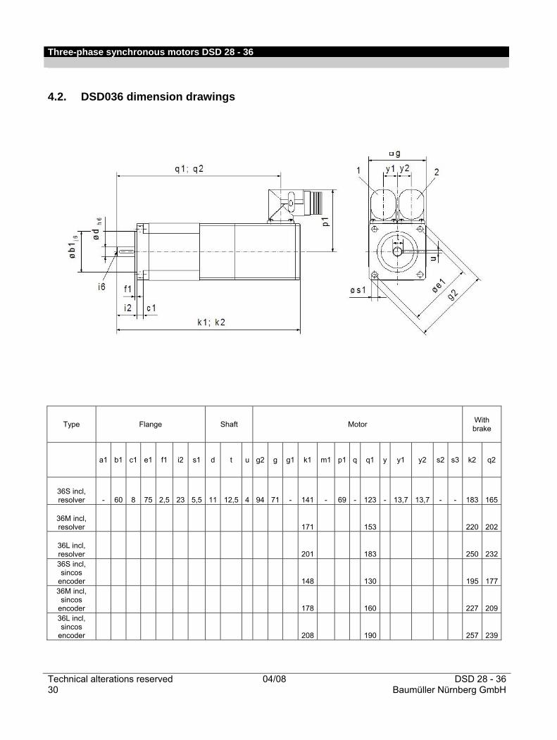
4.2. DSD036 dimension drawings
Type Flange Shaft Motor With brake
a1 b1 c1 e1 f1 i2 s1 d t u g2 g g1 k1 m1 p1 q q1 y y1 y2 s2 s3 k2 q2
36S incl, resolver - 60 8 75 2,5 23 5,5 11 12,5 4 94 71 - 141 - 69 - 123 - 13,7 13,7 - - 183 165
36M incl, resolver 171 153 220 202
36L incl, resolver 201 183 250 23236S incl, sincos
encoder 148 130 195 17736M incl,
sincos encoder 178 160 227 20936L incl, sincos
encoder 208 190 257 239

Three-phase synchronous motros DSD 28 - 36
DSD 28 - 36 04/08 Technical alterations reservedBaumüller Nürnberg GmbH 31
5. Commissioning and maintenance instructions When commissioning, please request the Commissioning and Maintenance Instructions version 01/2004).
6. Declaration of Conformity/Manufacturer's Declaration In this section we give general information on EC directives, CE marking and on the Declaration of Conformity/Manufacturer's Declaration.
6.1. What is an EC directive EC directives state requirements. The directives are compiled by the relevant authorities within the EU and are implemented in national law by all member states. In this way, the EC directives safeguard free trade within the EU. An EC directive contains only essential minimum requirements. You will find detailed requirements in standards that are referenced in the directive.
6.2. What does the CE mark signify? a) CE marking certifies conformity with all the obligations that need to be met by the manufacturer in relation to a product, based on the community directives containing provisions relating to CE marking. b) The CE mark applied to industrial products signifies that the natural or legal person who applies the mark or has the mark applied, has ensured that the product meets all Community directives on complete harmonization and has been subjected to all the conformity assessment procedures demanded by the regulations. Decision 93/465/EEC of the Council, Annex I B. a) + c) We apply the CE mark to the unit and to the documentation as soon as we have ascertained that we have met the requirements of the relevant directives. As long as this Baumüller product is used correctly within your overall machine, you can assume that the product complies with the requirements of 2006/95/EC. A key aspect for ensuring compliance with 89/336/EEC (EMC directive) is how this product is installed. Since you are performing the installation, you are also responsible for compliance with 89/336/EEC. We provide you with support in the form of EMC instructions. This information can be found in the relevant technical instructions. If you have met all the requirements stated in this documentation and in the technical instructions, you can assume (standard: ”suppose”) that the product complies with the requirements of the EMC directive. All national, local, and system-specific regulations must also be observed. To operate your machine in the EU, the following must be available:
Conformity mark (CE mark) Declaration(s) of Conformity in relation to the directive(s) relevant for the machine.
Three-phase synchronous motors DSD 28 - 36
Technical alterations reserved 04/08 DSD 28 - 3632 Baumüller Nürnberg GmbH
6.3. Declaration of Conformity, definition of term Within the context of this documentation, a Declaration of Conformity is a declaration that the electrical equipment placed on the market complies with all applicable essential health and safety requirements. With the Declaration of Conformity provided in this section, Baumüller Nürnberg GmbH declares that the product complies with the applicable essential health and safety requirements from the directives and standards that are listed in the Declaration of Conformity.
6.4. Manufacturer's Declaration, definition of term Within the context of this documentation, a Manufacturer's Declaration is a declaration that the machinery/safety components placed on the market complies with all applicable essential health and safety requirements. With the Manufacturer's Declaration provided in this section, Baumüller Nürnberg GmbH declares that the product complies with the applicable essential health and safety requirements from the directives and standards that are listed in the Manufacturer's Declaration. The product from Baumüller Nürnberg GmbH is installed in a machine. For the health and safety of the user (and others), it is important that the overall machine complies with all applicable essential health and safety requirements. For this reason Baumüller Nürnberg GmbH highlights in the Manufacturer's Declaration that the commissioning of the overall machine must be prohibited until it has been clarified that the machine complies with the stipulations of the Machinery Directive.
Three-phase synchronous motros DSD 28 - 36
DSD 28 - 36 04/08 Technical alterations reservedBaumüller Nürnberg GmbH 33
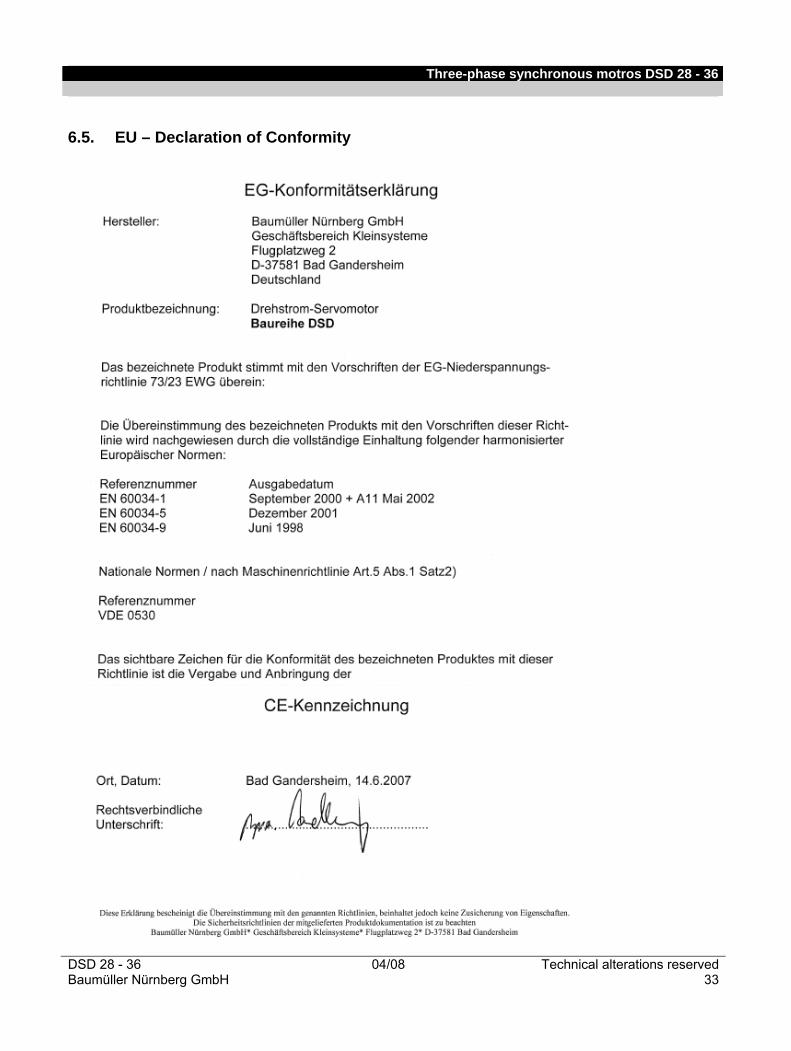
6.5. EU – Declaration of Conformity

Three-phase synchronous motors DSD 28 - 36
Technical alterations reserved 04/08 DSD 28 - 3634 Baumüller Nürnberg GmbH
Three-phase synchronous motros DSD 28 - 36
DSD 28 - 36 04/08 Technical alterations reservedBaumüller Nürnberg GmbH 35
Three-phase synchronous motors DSD 28 - 36
Technical alterations reserved 04/08 DSD 28 - 3636 Baumüller Nürnberg GmbH

Information subject to change
Headquarters
Subsidiaries
Baumüller Nürnberg GmbH Ostendstraße 80-90, 90482 Nürnberg T: +49(0)911 5432-0, F: +49(0)911 5432-130 www.baumueller.com Baumüller Anlagen-Systemtechnik GmbH & Co. KG Ostendstraße 84, 90482 Nürnberg T: +49(0)911 54408-0, F: +49(0)911 54408-769 www.baumueller.com Baumüller Reparaturwerk GmbH & Co. KG Andernacher Straße 19, 90411 Nürnberg T: +49(0)911 9552-0, F: +49(0)911 9552-999 www.baumueller.com Nürmont Installations GmbH & Co. KG Am Keuper 14, 90475 Nürnberg T: +49(0)9128 9255-0, F: +49(0)9128 9255-333 www.nuermont.com
Australia Baumüller Australia Pty. Ltd. 19 Baker Street, Botany NSW 2019, Sydney, T: +61 2 83350-100, F: +61 2 83350-169 Austria Baumüller Austria Ges.mbH Im Bäckerfeld 17, 4060 Leonding T: +43(0)732 674414-0, F: +43(0)732 674414-32 Brazil NC Service Indústria e Comércio Ltda. Av. Tamboré, 1217 Baruerí-SP, 06460-000 T: +55(0)11 4195-0502, F: +55(0)11 4195-2479 China Baumueller Automation Equipment Trading (Shanghai) Co. Ltd., Cailun Rd. 88, Pudong Zhangjiang, 201203 Shanghai, T: +86(0)21 5855 1533, F: +86(0)21 5855 9487 China Beijing Yanghai Automation Technology Co., Ltd.Room 1008, No.7, Huaqing Business Building, Iluaqing Garden, Wudaokou, Haidian District, 100083 Beijing, T: +86(0)10 8286 7980, F: +86(0)10 8286 7987 China Sunary Automatic Technology Limited Company 3rd Floor No.476, Chunxiao Rd., Zhangjiang High-Tech Park Pudong, Shanghai 201203, T: +86(0)21 5080 9898, F: +86(0)21 5308 7675 Czech Republic, Slovakia VAE Prosys s.r.o. Varsavska 9a, 70900 Ostrava T: +420 596 616 555, F: +420 596 616 777 Denmark Robotek EL & Teknik A/S Blokken 31, Postbox 30, 3460 Birkerød T: +45 4484 7360, F: +45 4484 4177 Finland Kontram Oy Olarinluoma 12, P.O.Box 88, 02201 Espoo T: +358 9 8866 4500, F: +358 9 8866 4799 France Baumüller France S.à.r.l. Zone de la Malnoue 39, Avenue de l´Europe, 77184 Emerainville T: +33(0)1 6461 6622, F: +33(0)1 6461 6006 France Baumüller France S.à.r.l. (Strasbourg) 9 rue de la Durance, 67100 Strasbourg T: +33(0)3 8840 1251, F: +33(0)3 8840 0724 Germany - Darmstadt Baumüller Nürnberg GmbH Waldstraße 1, 64347 Griesheim T: +49(0)6155 8430-00, F: +49(0)6155 8430-20 Germany - Düsseldorf Baumüller Nürnberg GmbH Jacob-Kaiser-Str. 7, 47877 Willich-Münchheide T: +49(0)2154 487-0, F: +49(0)2154 487-59 Germany - Dresden Baumüller Nürnberg GmbH Nordstraße 57, 01917 Kamenz T: +49(0)3578 3406-0, F: +49(0)3578 3406-50 Germany - Freiberg Nürmont Installations GmbH & Co. KG Am Junger Löwe Schacht 11, 09599 Freiberg T: +49(0)3731 3084-0, F: +49(0)3731 3084-33
Germany - Hannover Baumüller Nürnberg GmbH Bohlenweg 10, 30853 Langenhagen T: +49(0)511 771 968-0, F: +49(0)511 771 968-77 Germany - München Baumüller Reparaturwerk GmbH & Co. KG Meglingerstraße 58, 81477 München T: +49(0)89 748 898-0, F: +49(0)89 748 898-55 Germany - Nürnberg Baumüller Nürnberg GmbH Ostendstraße 80-90, 90482 Nürnberg T: +49(0)911 5432-501, F: +49(0)911 5432-510 Germany - Stuttgart Baumüller Nürnberg GmbH Im Ghai 12, 73776 Altbach T: +49(0)7153 61036-0, F: +49(0)7153 61036-29 Germany - Stuttgart Nürmont Installations GmbH & Co. KG Im Ghai 12, 73776 Altbach T: +49(0)7153 92798-0, F: +49(0)7153 92798-99 Great Britain Baumüller UK (South) Ltd. 14 Redlands Centre, Coulsdon, Surrey CR5 2HT T: +44(0)208 763-2990, F: +44(0)208 763-2959 Great Britain Baumüller UK (North) Ltd. Cyprus Buildung, Mossley, Lancashire, OL5 9BL, T: +44(0)1457 8374-95, F: +44(0)1457 8374-90 India Baumüller KAT India Pvt. Ltd. 4th Floor, Commerce Avenue, Mahaganesh Colony, Paud Road, 411038 Pune T: +91 20 254596 82, F: +91 20 254596 84 Italy Baumüller Italia S.r.l., Viale Italia 12, 20094 Corsico (Mi) T: +39 02 45100-181, F: +39 02 45100-426 Netherlands Baumüller Benelux B.V. Platinastraat 141, 2718 SR Zoetermeer T: +31(0)79 3614-290, F: +31(0)79 3614-339 Netherlands Baumüller Benelux B.V. Regenbeemd 6, 4825 AT Breda T: +31(0)79 3614-290, F: +31(0)79 3614-339 Poland Mekelburger Polska Ul. Kóscielna 39 F/3, 60537 Poznán, T: +48(0)61 8481 520, F: +48(0)61 8481 520 Russia, Kazakhstan Prosensor Zavadoskaj 1b/2, Moscow, 124365, T: +7 495 6428 476, F: +7 495 6428 477 Slovenia Baumüller Dravinja d.o.o. Delavska cesta 10, 3210 Slovenske-Konjice T: +386 3 75723-00, F: +386 3 75723-32/33 South Korea Bomac Systems 712 Yucheon Factophia, 196 Anyang-7 dong, Mananku, Anyangsi, Kyungkido 430-017, T: +82 31 467-2030, F: +82 31 467-2033
South Africa Motion Tronic cc Unit 18 Wareing Park, 3610 Pinetown T : +27 31 7011620, F : +27 86 6150597 Spain Baumüller Ibérica S.A. c/ Crom, 35-37, 2°2a, 08907 Hospitalet de Llobregat T: +34(0)93 263 0985, F: +34(0)93 263 2059 Switzerland Baumüller Suisse S.A. Rue Galilée 9, 1400 Yverdon-les Bains T: +41(0)24 420 77-70, F: +41(0)24 420 77-79 Switzerland Baumüller Schweiz AG (Büro Ost) Oberwiesenstraße 75, 8500 Frauenfeld T: +41(0)52 723 28-00, F: +41(0)52 723 28-01 Thailand Mr. Tom Sale and Service Co., Ltd. 39/9 Moo 1, Tepkanjana Rd., Tambol Nadee Amphur Muang, 74000 Samutsakorn T: +66 34 854932-4, F: +66 34 854935 Turkey Baumüller Motor Kontrol Sistem San. Ve Tic. Ltd. Sti Girne Mah., Kücükyali Is Merkezi, B Blok No. 12, Maltepe, 34852 Maltepe - Istanbul T: +90(0)216 519-9071, F: +90(0)216 519-9072 USA Baumueller Inc. 117 West Dudley Town Road, Bloomfield, CT 06002 T: +1 860-243-0232, F: +1 860-286-3080 USA Baumueller Inc. 1858 S. Elmhurst Road, Mount Prospect, IL 60005, T: +1 847-956-7392, F: +1 847-956-7925 USA Baumueller-Nuermont Corp. 1858 S. Elmhurst Road, Mount Prospect, IL 60005, T: +1 847-956-7392, F: +1 847-956-7925 USA Baumueller-Nuermont Corp. 2650 Pleasantdale Road, Suite 15, Doraville, GA 30340 T: +1 678-291-0535, F: +1 678-291-0537 Venezuela, Colombia, Ecuador Nimbus International C.A. C.C. Parque Tuy, Local P-18, Ocumare del Tuy, 1209 T: +58 239 225 1347, F: +58 239 225 7149
3.190.e.08/08.20M
04/08
e


Three-phase synchronous motors DS/DSD 45-100..540V
Three-phase synchronous motors 45 - 100 02/05 Technical alterations reserved Baumüller Nürnberg GmbH 1
Table of contents Three-phase synchronous motors DSD 45 - 100..540V....................................................................................3 General technical data ...........................................................................................................................................3 Explanation of the motor data ................................................................................................................................4 Type key .................................................................................................................................................................4 Technical data ........................................................................................................................................................5
DSD 045..64 U.. (IP 64 without fan).............................................................................................................5 DSD 056..64 U.. (IP 64 without fan).............................................................................................................6 DSD 056..54 O.. (IP 54 with fan)..................................................................................................................7 DSD 071..64 U.. (IP 64 without fan).............................................................................................................8 DSD 071..54 O.. (IP 54 with fan)..................................................................................................................9 DSD 100..64 U.. (IP 64 without fan)...........................................................................................................10 DSD 100..54 O.. (IP 54 with fan)................................................................................................................11
Radial force diagrams ..........................................................................................................................................12 Brake assignment.................................................................................................................................................15 Encoders ..............................................................................................................................................................16
Resolver .....................................................................................................................................................16 SINCOS SRS/SRM 50 (Stegmann) ...........................................................................................................17
Drawings...............................................................................................................................................................18 DSD 45 standard version, main connection with connector .....................................................................18 DSD 56 / 71 / 100 standard version, main connection with terminal box .................................................19 DSD 56 / 71 / 100 standard version, main connection with connector .....................................................20 DSD 56 / 71 / 100 standard version with fan, main connection with terminal box....................................21 DSD 56 / 71 / 100 standard version with fan, main connection with connector .......................................22
Motor cables .........................................................................................................................................................23 Nominal voltage..........................................................................................................................................23 Core lettering..............................................................................................................................................23 Cable data ..................................................................................................................................................23
Main connection cables / Assembled cable with connector.................................................................................25 Encoder cables.....................................................................................................................................................26 Commissioning and maintenance instructions.....................................................................................................27 Three-phase synchronous motors DS 45 - 100..540V ....................................................................................29 General technical data .........................................................................................................................................29 Ratings definition ..................................................................................................................................................30 Winding isolation and temperature rise................................................................................................................30 Explanation of the motor data ..............................................................................................................................30 Basic calculation...................................................................................................................................................30 Performance overview..........................................................................................................................................31 Type key ...............................................................................................................................................................31 Technical data ......................................................................................................................................................32
DS standard version...................................................................................................................................32 Radial force diagrams ..........................................................................................................................................38
DS in standard version or with fan .............................................................................................................39 DS in short version.....................................................................................................................................42
Main connection – terminal marking and connector assignment.........................................................................44 Thermal sensor.....................................................................................................................................................45 Fan data ...............................................................................................................................................................45 Brake assignment.................................................................................................................................................46
Three-phase synchronous motors DS/DSD 45-100..540V
Technical alterations reserved 02/05 Three-phase synchronous motors 45 - 100 2 Baumüller Nürnberg GmbH
Encoder ................................................................................................................................................................47
Resolver .....................................................................................................................................................47 SINCOS SRS/SRM 50 (Stegmann) ...........................................................................................................48 DS 56 / 71 / 100 standard version, main connection with terminal box....................................................49 DS 45 / 56 / 71 / 100 standard version, main connection with connector.................................................50 DS 56 / 71 / 100 standard version with fan, main connection with terminal box ......................................51 DS 56 / 71 / 100 standard version with fan, main connection with connector ..........................................52 DS 56 / 71 / 100 short version, main connection with terminal box..........................................................53 DS 56 / 71 / 100 short version, main connection with connector..............................................................54 Main connection, fan and male and female encoder connectors ..............................................................55
Motor cables .........................................................................................................................................................57 Nominal voltage..........................................................................................................................................57 Core lettering..............................................................................................................................................57 Cable data ..................................................................................................................................................57
Main connection cables / Assembled cable with connector.................................................................................59 Encoder cables.....................................................................................................................................................60 Commissioning and maintenance instructions.....................................................................................................61 Note: Preliminary DSD list! The technical data—electrical and mechanical—are subject to change! Date: 05/03 All information in this list represents nonbinding information for customers. The information is subject to continuous development and is continually being updated through our permanent updating service. Please note that data/numbers/information represent current values at the time of printing. This information is not legally binding for measurement, analysis and calculation. Before using any of the information listed in this bochure as the basis of personal calculations and/or applications, please ensure that the information you are using is current. No liability is assumed that the information presented here is correct

Three-phase synchronous motors DSD 45-100..540V
Three-phase synchronous motors 45 - 100 02/05 Technical alterations reserved Baumüller Nürnberg GmbH 3
Three-phase synchronous motors DSD 45 - 100..540V
General technical data
Version: IM B5 Horizontal mounting IM V1 Vertical mounting, shaft end to the bottom IM V3 Vertical mounting, shaft end to the top
Protection type: IP65 Surface-cooled, without fan, DIN 40050, DIN 40053 IP54 Surface-cooled, with fan
Shaft gland: IP64 Standard IP65 with shaft sealing ring (option)
Connection: Main connection U V W Terminal box
Connector (option) Frame size 45 with connector as standard
Control connection 12-pin connector Brake in the main connection
Thermal sensor in control connection (for resolver only) Cooling type: IC 0041 Completely enclosed machine surface-cooled no fan
IC 0641 as above, but with fan (air flow direction from B to A end) Thermal sensor: Linear thermal sensor for evaluation in the controller
Temperature rise: ∆ϑ = 105K Insulation class F acc. to EN 60034 Temperature range: 0....+ 40°C
Storage: -30°C...+85°C Paint: black matt RAL 9005
Bearing: ≥ 20,000h Service life Balance quality: N According to DIN ISO 2373
R, S On request Vibration resistant up
to: radial 3g 20 Hz to 2 kHz acc. to EN 60068-2-6
axial 0.5g 20 Hz to 2 kHz acc. to EN 60068-2-6 Higher vibration resistance on request
Flange: acc. to IEC standard Dimension b1: Tolerance j6 Shaft end: cylindrical Smooth acc. to DIN 748; (also available with key DIN 6885)
Dimension d: Tolerance k6 Centering with internal thread acc. to DIN 332 form D
Holding brake: Option Actual speed encoder: 2-pin resolver
Sincos encoder (option) Other encoders on request
New design for frame size 56/71/100 available from October 2003. Frame size 45 is already available.
Three-phase synchronous motors DSD 45-100..540V
Technical alterations reserved 02/05 Three-phase synchronous motors 45 - 100 4 Baumüller Nürnberg GmbH
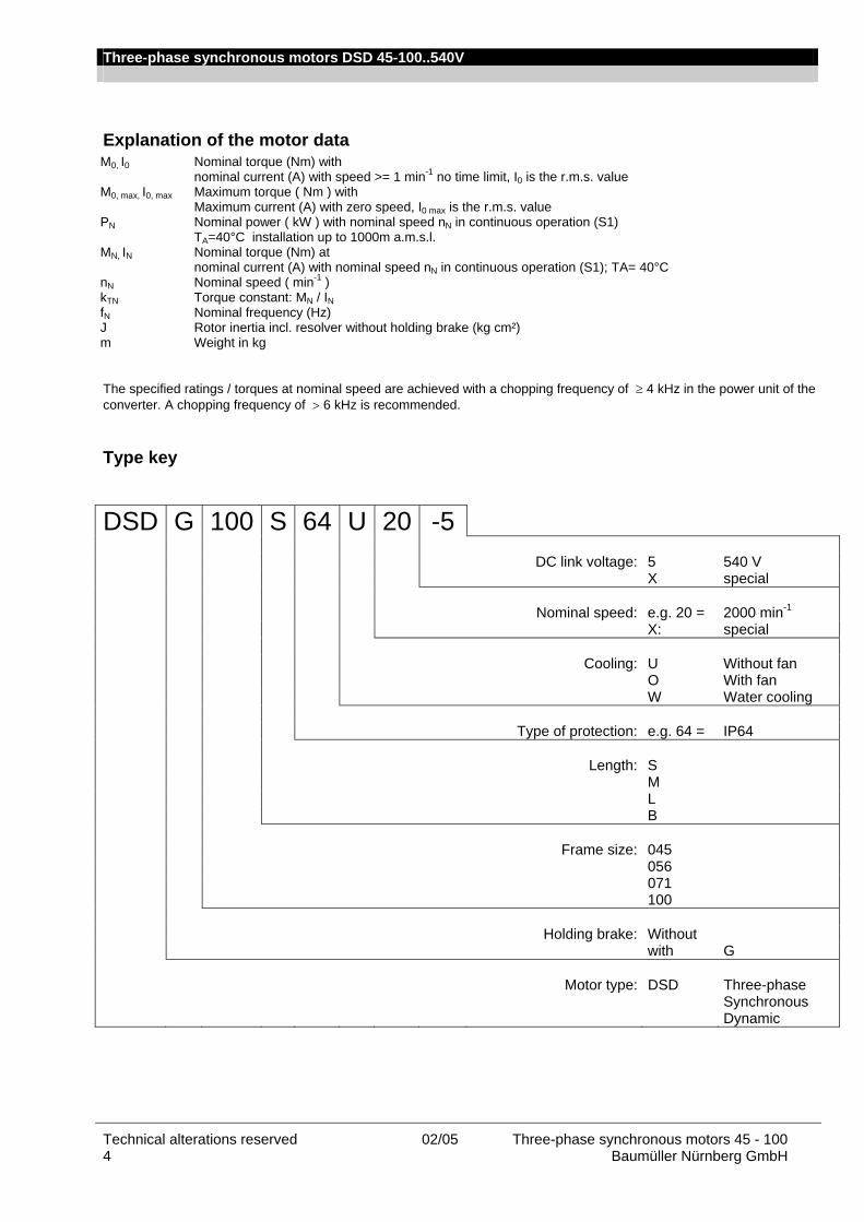
Explanation of the motor data M0, I0 Nominal torque (Nm) with nominal current (A) with speed >= 1 min-1 no time limit, I0 is the r.m.s. value M0, max, I0, max Maximum torque ( Nm ) with Maximum current (A) with zero speed, I0 max is the r.m.s. value PN Nominal power ( kW ) with nominal speed nN in continuous operation (S1) TA=40°C installation up to 1000m a.m.s.l. MN, IN Nominal torque (Nm) at nominal current (A) with nominal speed nN in continuous operation (S1); TA= 40°C nN Nominal speed ( min-1 ) kTN Torque constant: MN / IN
fN Nominal frequency (Hz) J Rotor inertia incl. resolver without holding brake (kg cm²) m Weight in kg The specified ratings / torques at nominal speed are achieved with a chopping frequency of ≥ 4 kHz in the power unit of the converter. A chopping frequency of > 6 kHz is recommended.
Type key
DSD G 100 S 64 U 20 -5 DC link voltage: 5 540 V X special Nominal speed: e.g. 20 = 2000 min-1 X: special Cooling: U Without fan O With fan W Water cooling Type of protection: e.g. 64 = IP64 Length: S M L B Frame size: 045 056 071 100 Holding brake: Without with G Motor type: DSD Three-phase
Synchronous Dynamic
Three-phase synchronous motors DSD 45-100..540V
Three-phase synchronous motors 45 - 100 02/05 Technical alterations reserved Baumüller Nürnberg GmbH 5
Technical data
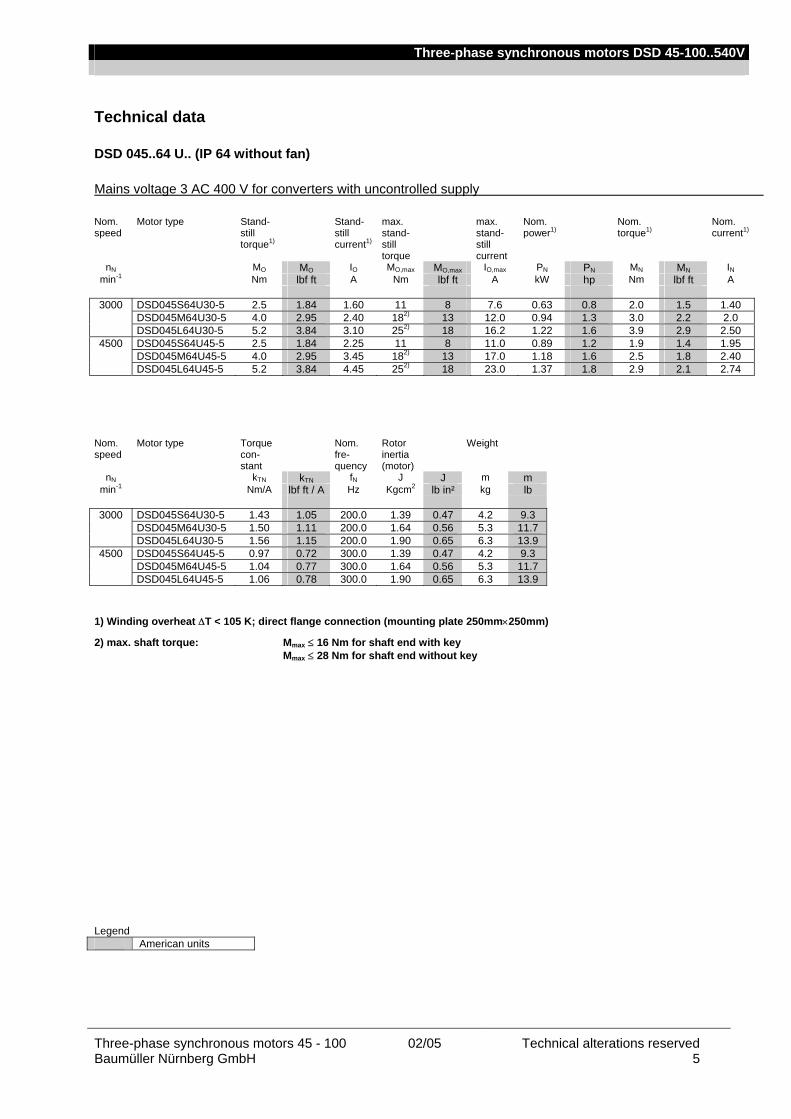
DSD 045..64 U.. (IP 64 without fan)
Mains voltage 3 AC 400 V for converters with uncontrolled supply Nom. speed
Motor type Stand-still torque1)
Stand-still current1)
max. stand-still torque
max. stand-still current
Nom. power1)
Nom. torque1)
Nom. current1)
nN MO MO IO MO,max MO,max IO,max PN PN MN MN IN min-1 Nm lbf ft A Nm lbf ft A kW hp Nm lbf ft A
3000 DSD045S64U30-5 2.5 1.84 1.60 11 8 7.6 0.63 0.8 2.0 1.5 1.40
DSD045M64U30-5 4.0 2.95 2.40 182) 13 12.0 0.94 1.3 3.0 2.2 2.0 DSD045L64U30-5 5.2 3.84 3.10 252) 18 16.2 1.22 1.6 3.9 2.9 2.50
4500 DSD045S64U45-5 2.5 1.84 2.25 11 8 11.0 0.89 1.2 1.9 1.4 1.95 DSD045M64U45-5 4.0 2.95 3.45 182) 13 17.0 1.18 1.6 2.5 1.8 2.40 DSD045L64U45-5 5.2 3.84 4.45 252) 18 23.0 1.37 1.8 2.9 2.1 2.74
Nom. speed
Motor type Torque con-stant
Nom. fre-quency
Rotor inertia (motor)
Weight
nN kTN kTN fN J J m m min-1 Nm/A lbf ft / A Hz Kgcm2 lb in² kg lb
3000 DSD045S64U30-5 1.43 1.05 200.0 1.39 0.47 4.2 9.3
DSD045M64U30-5 1.50 1.11 200.0 1.64 0.56 5.3 11.7 DSD045L64U30-5 1.56 1.15 200.0 1.90 0.65 6.3 13.9
4500 DSD045S64U45-5 0.97 0.72 300.0 1.39 0.47 4.2 9.3 DSD045M64U45-5 1.04 0.77 300.0 1.64 0.56 5.3 11.7 DSD045L64U45-5 1.06 0.78 300.0 1.90 0.65 6.3 13.9
1) Winding overheat ∆T < 105 K; direct flange connection (mounting plate 250mm×250mm)
2) max. shaft torque: Mmax ≤ 16 Nm for shaft end with key Mmax ≤ 28 Nm for shaft end without key Legend American units
Three-phase synchronous motors DSD 45-100..540V
Technical alterations reserved 02/05 Three-phase synchronous motors 45 - 100 6 Baumüller Nürnberg GmbH
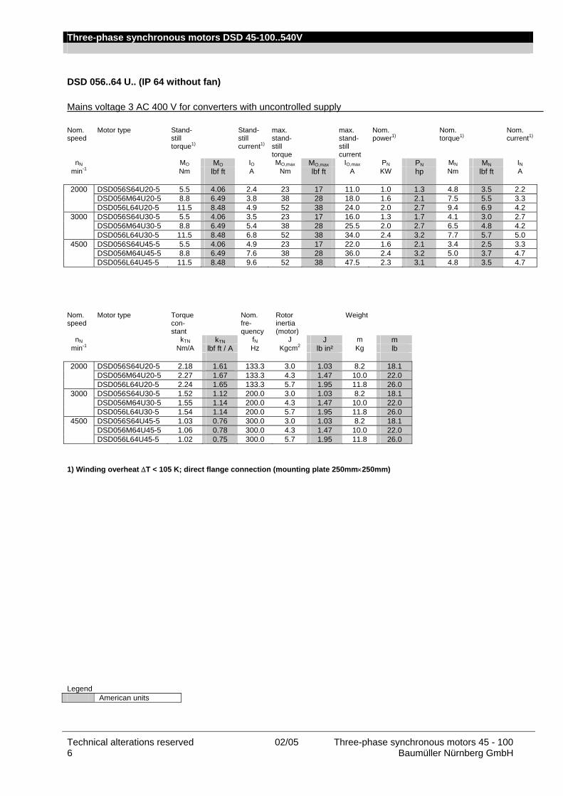
DSD 056..64 U.. (IP 64 without fan)
Mains voltage 3 AC 400 V for converters with uncontrolled supply Nom. speed
Motor type Stand-still torque1)
Stand-still current1)
max. stand-still torque
max. stand-still current
Nom. power1)
Nom. torque1)
Nom. current1)
nN MO MO IO MO,max MO,max IO,max PN PN MN MN IN min-1 Nm lbf ft A Nm lbf ft A KW hp Nm lbf ft A
2000 DSD056S64U20-5 5.5 4.06 2.4 23 17 11.0 1.0 1.3 4.8 3.5 2.2
DSD056M64U20-5 8.8 6.49 3.8 38 28 18.0 1.6 2.1 7.5 5.5 3.3 DSD056L64U20-5 11.5 8.48 4.9 52 38 24.0 2.0 2.7 9.4 6.9 4.2
3000 DSD056S64U30-5 5.5 4.06 3.5 23 17 16.0 1.3 1.7 4.1 3.0 2.7 DSD056M64U30-5 8.8 6.49 5.4 38 28 25.5 2.0 2.7 6.5 4.8 4.2 DSD056L64U30-5 11.5 8.48 6.8 52 38 34.0 2.4 3.2 7.7 5.7 5.0
4500 DSD056S64U45-5 5.5 4.06 4.9 23 17 22.0 1.6 2.1 3.4 2.5 3.3 DSD056M64U45-5 8.8 6.49 7.6 38 28 36.0 2.4 3.2 5.0 3.7 4.7 DSD056L64U45-5 11.5 8.48 9.6 52 38 47.5 2.3 3.1 4.8 3.5 4.7
Nom. speed
Motor type Torque con-stant
Nom. fre-quency
Rotor inertia (motor)
Weight
nN kTN kTN fN J J m m min-1 Nm/A lbf ft / A Hz Kgcm2 lb in² Kg lb
2000 DSD056S64U20-5 2.18 1.61 133.3 3.0 1.03 8.2 18.1
DSD056M64U20-5 2.27 1.67 133.3 4.3 1.47 10.0 22.0 DSD056L64U20-5 2.24 1.65 133.3 5.7 1.95 11.8 26.0
3000 DSD056S64U30-5 1.52 1.12 200.0 3.0 1.03 8.2 18.1 DSD056M64U30-5 1.55 1.14 200.0 4.3 1.47 10.0 22.0 DSD056L64U30-5 1.54 1.14 200.0 5.7 1.95 11.8 26.0
4500 DSD056S64U45-5 1.03 0.76 300.0 3.0 1.03 8.2 18.1 DSD056M64U45-5 1.06 0.78 300.0 4.3 1.47 10.0 22.0 DSD056L64U45-5 1.02 0.75 300.0 5.7 1.95 11.8 26.0
1) Winding overheat ∆T < 105 K; direct flange connection (mounting plate 250mm×250mm) Legend American units

Three-phase synchronous motors DSD 45-100..540V
Three-phase synchronous motors 45 - 100 02/05 Technical alterations reserved Baumüller Nürnberg GmbH 7
DSD 056..54 O.. (IP 54 with fan)
Mains voltage 3 AC 400 V for converters with uncontrolled supply Nom. speed
Motor type Stand-still torque1)
Stand-still current1)
max. stand-still torque
Max. stand-still current
Nom. power1)
Nom. torque1)
Nom. current1)
nN MO MO IO MO,max MO,max IO,max PN PN MN MN IN min-1 Nm lbf ft A Nm lbf ft A KW hp Nm lbf ft A
2000 DSD056S54O20-5 7.2 5.31 3.2 23 17 11.0 1.4 1.9 6.6 4.9 3.0
DSD056M54O20-5 11.8 8.7 5.1 38 28 18.0 2.3 3.1 11.0 8.1 4.9 DSD056L54O20-5 15.5 11.4 6.7 52 38 24.0 3.0 4.0 14.2 10.5 6.3
3000 DSD056S54O30-5 7.2 5.31 4.6 23 17 16.0 2.0 2.7 6.3 4.6 4.1 DSD056M54O30-5 11.8 8.7 7.3 38 28 25.5 3.3 4.4 10.4 7.7 6.6 DSD056L54O30-5 15.5 11.4 9.4 52 38 34.0 4.1 5.5 13.0 9.6 8.2
4500 DSD056S54O45-5 7.2 5.31 6.4 23 17 22.0 2.6 3.5 5.5 4.1 5.2 DSD056M54O45-5 11.8 8.7 10.3 38 28 36.0 4.2 5.6 9.0 6.6 8.2 DSD056L54O45-5 15.5 11.4 13.0 52 38 47.5 5.4 7.2 11.4 8.4 10.5
Nom. speed
Motor type Torque con-stant
Nom. fre-quency
Rotor inertia (motor)
Weight
nN kTN kTN fN J J m m min-1 Nm/A lbf ft / A Hz Kgcm2 lb in² Kg lb
2000 DSD056S54O20-5 2.20 1.62 133.3 3.0 1.03 11.0 24.3
DSD056M54O20-5 2.24 1.65 133.3 4.3 1.47 12.8 28.2 DSD056L54O20-5 2.25 1.66 133.3 5.7 1.95 14.6 32.2
3000 DSD056S54O30-5 1.54 1.14 200.0 3.0 1.03 11.0 24.3 DSD056M54O30-5 1.58 1.17 200.0 4.3 1.47 12.8 28.2 DSD056L54O30-5 1.58 1.17 200.0 5.7 1.95 14.6 32.2
4500 DSD056S54O45-5 1.06 0.78 300.0 3.0 1.03 11.0 24.3 DSD056M54O45-5 1.10 0.81 300.0 4.3 1.47 12.8 28.2 DSD056L54O45-5 1.09 0.80 300.0 5.7 1.95 14.6 32.2
1) Winding overheat ∆T < 105 K; direct flange connection (mounting plate 250mm×250mm) Legend American units
Three-phase synchronous motors DSD 45-100..540V
Technical alterations reserved 02/05 Three-phase synchronous motors 45 - 100 8 Baumüller Nürnberg GmbH
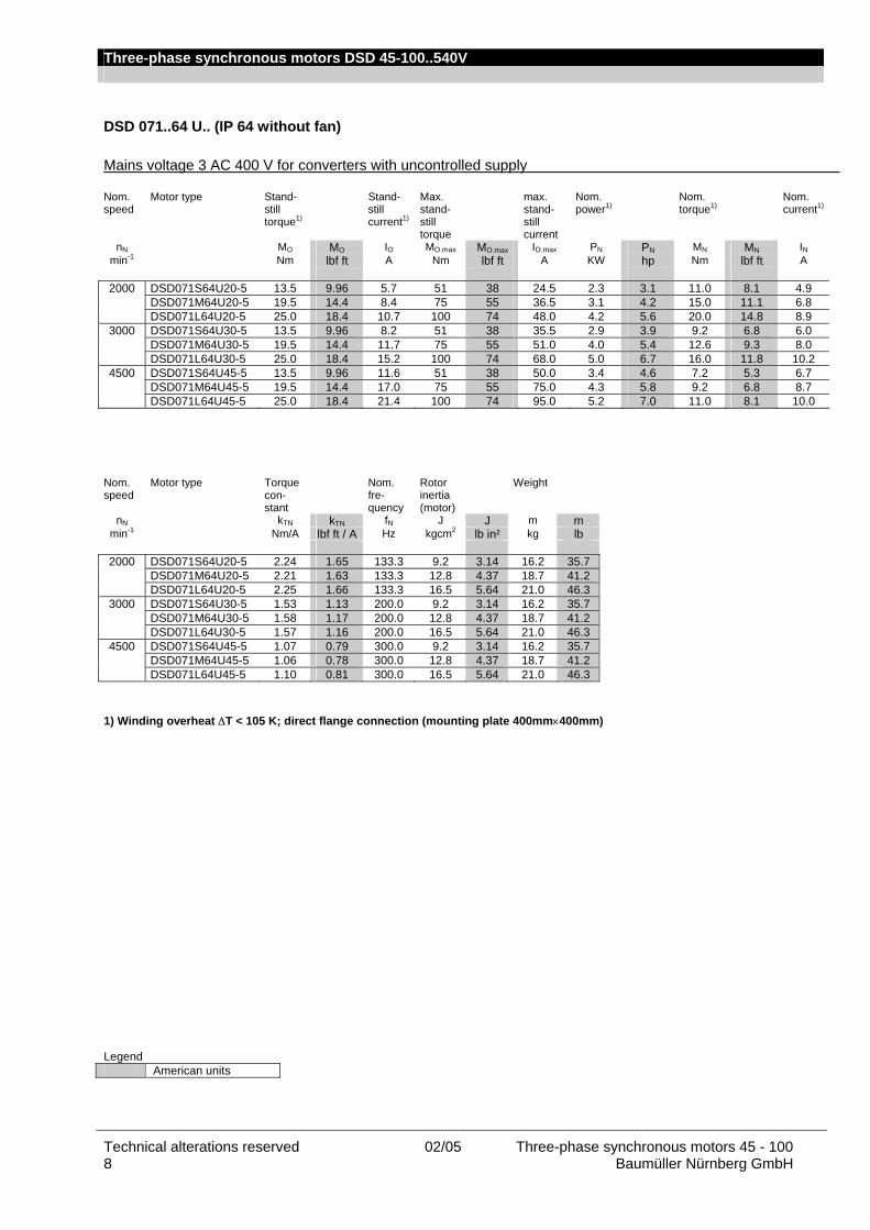
DSD 071..64 U.. (IP 64 without fan)
Mains voltage 3 AC 400 V for converters with uncontrolled supply Nom. speed
Motor type Stand-still torque1)
Stand-still current1)
Max. stand-still torque
max. stand-still current
Nom. power1)
Nom. torque1)
Nom. current1)
nN MO MO IO MO.max MO.max IO.max PN PN MN MN IN min-1 Nm lbf ft A Nm lbf ft A KW hp Nm lbf ft A
2000 DSD071S64U20-5 13.5 9.96 5.7 51 38 24.5 2.3 3.1 11.0 8.1 4.9
DSD071M64U20-5 19.5 14.4 8.4 75 55 36.5 3.1 4.2 15.0 11.1 6.8 DSD071L64U20-5 25.0 18.4 10.7 100 74 48.0 4.2 5.6 20.0 14.8 8.9
3000 DSD071S64U30-5 13.5 9.96 8.2 51 38 35.5 2.9 3.9 9.2 6.8 6.0 DSD071M64U30-5 19.5 14.4 11.7 75 55 51.0 4.0 5.4 12.6 9.3 8.0 DSD071L64U30-5 25.0 18.4 15.2 100 74 68.0 5.0 6.7 16.0 11.8 10.2
4500 DSD071S64U45-5 13.5 9.96 11.6 51 38 50.0 3.4 4.6 7.2 5.3 6.7 DSD071M64U45-5 19.5 14.4 17.0 75 55 75.0 4.3 5.8 9.2 6.8 8.7 DSD071L64U45-5 25.0 18.4 21.4 100 74 95.0 5.2 7.0 11.0 8.1 10.0
Nom. speed
Motor type Torque con-stant
Nom. fre-quency
Rotor inertia (motor)
Weight
nN kTN kTN fN J J m m min-1 Nm/A lbf ft / A Hz kgcm2 lb in² kg lb
2000 DSD071S64U20-5 2.24 1.65 133.3 9.2 3.14 16.2 35.7
DSD071M64U20-5 2.21 1.63 133.3 12.8 4.37 18.7 41.2 DSD071L64U20-5 2.25 1.66 133.3 16.5 5.64 21.0 46.3
3000 DSD071S64U30-5 1.53 1.13 200.0 9.2 3.14 16.2 35.7 DSD071M64U30-5 1.58 1.17 200.0 12.8 4.37 18.7 41.2 DSD071L64U30-5 1.57 1.16 200.0 16.5 5.64 21.0 46.3
4500 DSD071S64U45-5 1.07 0.79 300.0 9.2 3.14 16.2 35.7 DSD071M64U45-5 1.06 0.78 300.0 12.8 4.37 18.7 41.2 DSD071L64U45-5 1.10 0.81 300.0 16.5 5.64 21.0 46.3
1) Winding overheat ∆T < 105 K; direct flange connection (mounting plate 400mm×400mm) Legend American units
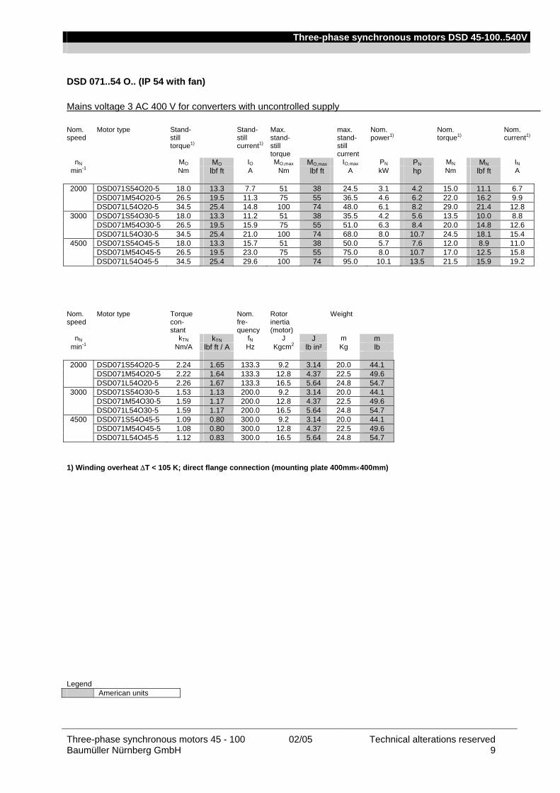
Three-phase synchronous motors DSD 45-100..540V
Three-phase synchronous motors 45 - 100 02/05 Technical alterations reserved Baumüller Nürnberg GmbH 9
DSD 071..54 O.. (IP 54 with fan)
Mains voltage 3 AC 400 V for converters with uncontrolled supply Nom. speed
Motor type Stand-still torque1)
Stand-still current1)
Max. stand-still torque
max. stand-still current
Nom. power1)
Nom. torque1)
Nom. current1)
nN MO MO IO MO,max MO,max IO,max PN PN MN MN IN min-1 Nm lbf ft A Nm lbf ft A kW hp Nm lbf ft A
2000 DSD071S54O20-5 18.0 13.3 7.7 51 38 24.5 3.1 4.2 15.0 11.1 6.7
DSD071M54O20-5 26.5 19.5 11.3 75 55 36.5 4.6 6.2 22.0 16.2 9.9 DSD071L54O20-5 34.5 25.4 14.8 100 74 48.0 6.1 8.2 29.0 21.4 12.8
3000 DSD071S54O30-5 18.0 13.3 11.2 51 38 35.5 4.2 5.6 13.5 10.0 8.8 DSD071M54O30-5 26.5 19.5 15.9 75 55 51.0 6.3 8.4 20.0 14.8 12.6 DSD071L54O30-5 34.5 25.4 21.0 100 74 68.0 8.0 10.7 24.5 18.1 15.4
4500 DSD071S54O45-5 18.0 13.3 15.7 51 38 50.0 5.7 7.6 12.0 8.9 11.0 DSD071M54O45-5 26.5 19.5 23.0 75 55 75.0 8.0 10.7 17.0 12.5 15.8 DSD071L54O45-5 34.5 25.4 29.6 100 74 95.0 10.1 13.5 21.5 15.9 19.2
Nom. speed
Motor type Torque con-stant
Nom. fre-quency
Rotor inertia (motor)
Weight
nN kTN kTN fN J J m m min-1 Nm/A lbf ft / A Hz Kgcm2 lb in² Kg lb
2000 DSD071S54O20-5 2.24 1.65 133.3 9.2 3.14 20.0 44.1
DSD071M54O20-5 2.22 1.64 133.3 12.8 4.37 22.5 49.6 DSD071L54O20-5 2.26 1.67 133.3 16.5 5.64 24.8 54.7
3000 DSD071S54O30-5 1.53 1.13 200.0 9.2 3.14 20.0 44.1 DSD071M54O30-5 1.59 1.17 200.0 12.8 4.37 22.5 49.6 DSD071L54O30-5 1.59 1.17 200.0 16.5 5.64 24.8 54.7
4500 DSD071S54O45-5 1.09 0.80 300.0 9.2 3.14 20.0 44.1 DSD071M54O45-5 1.08 0.80 300.0 12.8 4.37 22.5 49.6 DSD071L54O45-5 1.12 0.83 300.0 16.5 5.64 24.8 54.7
1) Winding overheat ∆T < 105 K; direct flange connection (mounting plate 400mm×400mm) Legend American units

Three-phase synchronous motors DSD 45-100..540V
Technical alterations reserved 02/05 Three-phase synchronous motors 45 - 100 10 Baumüller Nürnberg GmbH
DSD 100..64 U.. (IP 64 without fan)
Mains voltage 3 AC 400 V for converters with uncontrolled supply Nom. speed
Motor type Stand-still torque1)
Stand-still current1)
max. stand-still torque
max. stand-still current
Nom. power1)
Nom. torque1)
Nom. current1)
nN MO MO IO MO,max MO,max IO,max PN PN MN MN IN min-1 Nm lbf ft A Nm lbf ft A KW hp Nm lbf ft A
1200 DSD100S64U12-5 34.0 25.1 9.1 105 77 33 3.8 5.1 30.0 22.1 8.3
DSD100M64U12-5 51.0 37.6 13.7 158 117 49 5.6 7.5 44.5 32.8 12.3 DSD100L64U12-5 66.5 49 18.0 210 155 66 7.0 9.4 56.0 41.3 15.5
2000 DSD100S64U20-5 34.0 25.1 14.5 105 77 52 5.4 7.2 26.0 19.2 11.5 DSD100M64U20-5 51.0 37.6 21.0 158 117 75 7.7 10.3 37.0 27.3 16.0 DSD100L64U20-5 66.5 49 27.5 210 155 102 9.4 12.6 45.0 33.2 19.5
3000 DSD100S64U30-5 34.0 25.1 21.5 105 77 76 6.6 8.9 21.0 15.5 13.5 DSD100M64U30-5 51.0 37.6 30.5 158 117 110 9.0 12.1 28.5 21.0 18.5 DSD100L64U30-5 66.5 49 40.0 210 155 147 10.7 14.3 34.0 25.1 21.5
4500 DSD100S64U45-5 34.0 25.1 30.5 105 77 110 5.9 7.9 12.5 9.2 11.7 DSD100M64U45-5 51.0 37.6 44.0 158 117 157 7.5 10.1 16.0 11.8 15.0
Nom. speed
Motor type Torque con-stant
Nom. fre-quency
Rotor inertia (motor)
Weight
nN kTN kTN fN J J m m min-1 Nm/A lbf ft / A Hz Kgcm2 lb in² kg lb
1200 DSD100S64U12-5 3.61 2.66 80.0 42.5 14.52 31.0 68.3
DSD100M64U12-5 3.62 2.67 80.0 60.0 20.50 38.5 84.9 DSD100L64U12-5 3.61 2.66 80.0 77.0 26.31 45.5 100.3
2000 DSD100S64U20-5 2.26 1.67 133.3 42.5 14.52 31.0 68.3 DSD100M64U20-5 2.31 1.70 133.3 60.0 20.50 38.5 84.9 DSD100L64U20-5 2.31 1.70 133.3 77.0 26.31 45.5 100.3
3000 DSD100S64U30-5 1.56 1.15 200.0 42.5 14.52 31.0 68.3 DSD100M64U30-5 1.54 1.14 200.0 60.0 20.50 38.5 84.9 DSD100L64U30-5 1.58 1.17 200.0 77.0 26.31 45.5 100.3
4500 DSD100S64U45-5 1.07 0.79 300.0 42.5 14.52 31.0 68.3 DSD100M64U45-5 1.07 0.79 300.0 60.0 20.50 38.5 84.9
1) Winding overheat ∆T < 105 K; direct flange connection (mounting plate 400mm×400mm) Legend American units
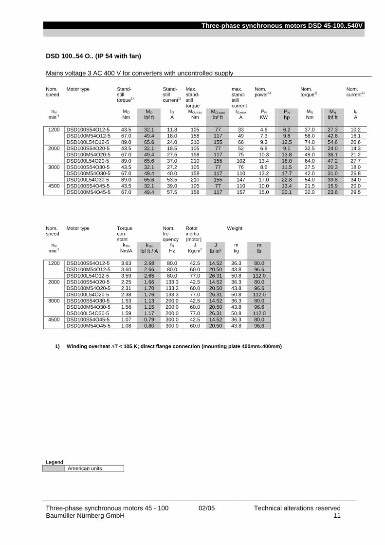
Three-phase synchronous motors DSD 45-100..540V
Three-phase synchronous motors 45 - 100 02/05 Technical alterations reserved Baumüller Nürnberg GmbH 11
DSD 100..54 O.. (IP 54 with fan)
Mains voltage 3 AC 400 V for converters with uncontrolled supply Nom. speed
Motor type Stand-still torque1)
Stand-still current1)
Max. stand-still torque
max. stand-still current
Nom. power1)
Nom. torque1)
Nom. current1)
nN MO MO IO MO,max MO,max IO,max PN PN MN MN IN min-1 Nm lbf ft A Nm lbf ft A KW hp Nm lbf ft A
1200 DSD100S54O12-5 43.5 32.1 11.8 105 77 33 4.6 6.2 37.0 27.3 10.2
DSD100M54O12-5 67.0 49.4 18.0 158 117 49 7.3 9.8 58.0 42.8 16.1 DSD100L54O12-5 89.0 65.6 24.0 210 155 66 9.3 12.5 74.0 54.6 20.6
2000 DSD100S54O20-5 43.5 32.1 18.5 105 77 52 6.8 9.1 32.5 24.0 14.3 DSD100M54O20-5 67.0 49.4 27.5 158 117 75 10.3 13.8 49.0 36.1 21.2 DSD100L54O20-5 89.0 65.6 37.0 210 155 102 13.4 18.0 64.0 47.2 27.7
3000 DSD100S54O30-5 43.5 32.1 27.2 105 77 76 8.6 11.5 27.5 20.3 18.0 DSD100M54O30-5 67.0 49.4 40.0 158 117 110 13.2 17.7 42.0 31.0 26.8 DSD100L54O30-5 89.0 65.6 53.5 210 155 147 17.0 22.8 54.0 39.8 34.0
4500 DSD100S54O45-5 43.5 32.1 39.0 105 77 110 10.0 13.4 21.5 15.9 20.0 DSD100M54O45-5 67.0 49.4 57.5 158 117 157 15.0 20.1 32.0 23.6 29.5
Nom. speed
Motor type Torque con-stant
Nom. fre-quency
Rotor inertia (motor)
Weight
nN kTN kTN fN J J m m min-1 Nm/A lbf ft / A Hz Kgcm2 lb in² kg lb
1200 DSD100S54O12-5 3.63 2.68 80.0 42.5 14.52 36.3 80.0
DSD100M54O12-5 3.60 2.66 80.0 60.0 20.50 43.8 96.6 DSD100L54O12-5 3.59 2.65 80.0 77.0 26.31 50.8 112.0
2000 DSD100S54O20-5 2.25 1.66 133.3 42.5 14.52 36.3 80.0 DSD100M54O20-5 2.31 1.70 133.3 60.0 20.50 43.8 96.6 DSD100L54O20-5 2.38 1.76 133.3 77.0 26.31 50.8 112.0
3000 DSD100S54O30-5 1.53 1.13 200.0 42.5 14.52 36.3 80.0 DSD100M54O30-5 1.56 1.15 200.0 60.0 20.50 43.8 96.6 DSD100L54O30-5 1.59 1.17 200.0 77.0 26.31 50.8 112.0
4500 DSD100S54O45-5 1.07 0.79 300.0 42.5 14.52 36.3 80.0 DSD100M54O45-5 1.08 0,80 300.0 60.0 20,50 43.8 96,6
1) Winding overheat ∆T < 105 K; direct flange connection (mounting plate 400mm×400mm) Legend American units

Three-phase synchronous motors DSD 45-100..540V
Technical alterations reserved 02/05 Three-phase synchronous motors 45 - 100 12 Baumüller Nürnberg GmbH
Radial force diagrams
Permissible radial forces FR at the shaft end All bearings are dimensioned for a service life of approx. 20,000 operating hours; the loads specified in the following must not be exceeded. The specified permissible radial forces FR are valid only for horizontal mounting of the motor without additional axial forces. Axial load of the motor shaft When mounting clutches, pulleys, etc. onto the motor shaft, axial forces must not occur! Therefore use the internal thread of the shaft end as assembly aid. Example Force acting on the end of the shaft end (for force acting on the middle of the shaft end Fr x 1.1) Bearing life 20,000 h; shaft end with keyway
0
1000
2000
3000
4000
5000
6000
7000
8000
9000
10000
0 500 1000 1500 2000 2500 3000 3500 4000 4500
Fr [ N ]
n [ 1
/min
]
0
50
100
150
200
250
M [
Nm
]
Kugellager / Ball bearing Welle / Shaft
Welle
Kugellager
Explanation of the example The radial force Fr of the application is used to determine the possible maximum speed of the bearing in the “Ball bearing” characteristic.
Radial force 850 N => maximum speed 4250 min-1
The maximum transmittable torque results from the “Shaft” characteristic. Radial force 850 N => maximum transmittable torque 185 Nm
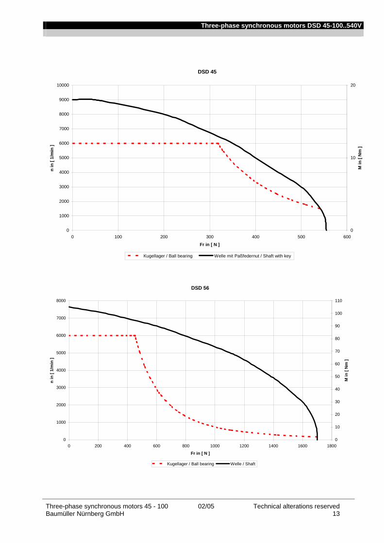
Three-phase synchronous motors DSD 45-100..540V
Three-phase synchronous motors 45 - 100 02/05 Technical alterations reserved Baumüller Nürnberg GmbH 13
DSD 45
0
1000
2000
3000
4000
5000
6000
7000
8000
9000
10000
0 100 200 300 400 500 600
Fr in [ N ]
n in
[ 1/
min
]
0
10
20
M in
[ N
m ]
Kugellager / Ball bearing Welle mit Paßfedernut / Shaft with key
DSD 56
0
1000
2000
3000
4000
5000
6000
7000
8000
0 200 400 600 800 1000 1200 1400 1600 1800
Fr in [ N ]
n in
[ 1/
min
]
0
10
20
30
40
50
60
70
80
90
100
110
M in
[ N
m ]
Kugellager / Ball bearing Welle / Shaft

Three-phase synchronous motors DSD 45-100..540V
Technical alterations reserved 02/05 Three-phase synchronous motors 45 - 100 14 Baumüller Nürnberg GmbH
DSD 71
0
1000
2000
3000
4000
5000
6000
7000
8000
0 200 400 600 800 1000 1200 1400 1600 1800 2000 2200 2400 2600
Fr in [ N ]
n in
[ 1/
min
]
0
20
40
60
80
100
120
140
160
180
M in
[ N
m ]
Kugellager / Ball bearing Rollenlager / Roller bearing Welle / Shaft
DSD 100
0
1000
2000
3000
4000
5000
6000
7000
8000
9000
10000
0 500 1000 1500 2000 2500 3000 3500 4000 4500 5000
Fr in [ N ]
n in
[ 1/
min
]
0
40
80
120
160
200
240
280
320
360
400
440
480
M in
[ N
m ]
Kugellager / Ball bearing Rollenlager / Roller bearing Welle / Shaft
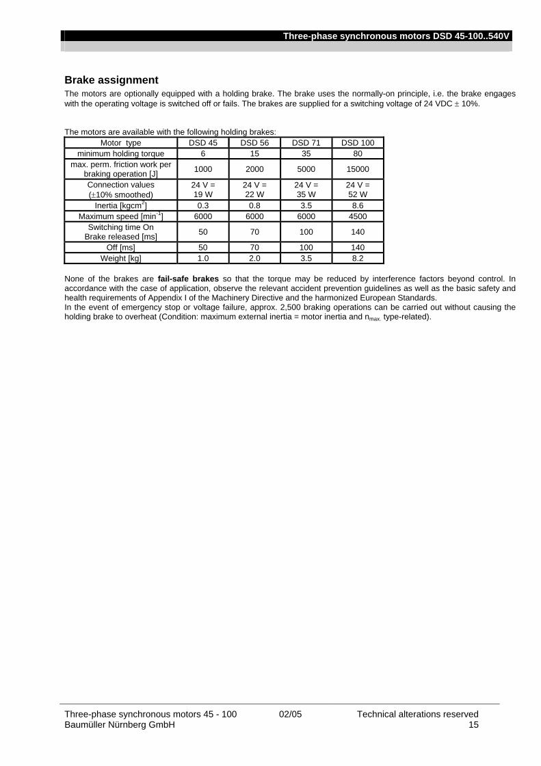
Three-phase synchronous motors DSD 45-100..540V
Three-phase synchronous motors 45 - 100 02/05 Technical alterations reserved Baumüller Nürnberg GmbH 15
Brake assignment The motors are optionally equipped with a holding brake. The brake uses the normally-on principle, i.e. the brake engages with the operating voltage is switched off or fails. The brakes are supplied for a switching voltage of 24 VDC ± 10%.
The motors are available with the following holding brakes:
Motor type DSD 45 DSD 56 DSD 71 DSD 100 minimum holding torque 6 15 35 80
max. perm. friction work per braking operation [J] 1000 2000 5000 15000
Connection values (±10% smoothed)
24 V = 19 W
24 V = 22 W
24 V = 35 W
24 V = 52 W
Inertia [kgcm2] 0.3 0.8 3.5 8.6 Maximum speed [min-1] 6000 6000 6000 4500
Switching time On Brake released [ms] 50 70 100 140
Off [ms] 50 70 100 140 Weight [kg] 1.0 2.0 3.5 8.2
None of the brakes are fail-safe brakes so that the torque may be reduced by interference factors beyond control. In accordance with the case of application, observe the relevant accident prevention guidelines as well as the basic safety and health requirements of Appendix I of the Machinery Directive and the harmonized European Standards. In the event of emergency stop or voltage failure, approx. 2,500 braking operations can be carried out without causing the holding brake to overheat (Condition: maximum external inertia = motor inertia and nmax. type-related).
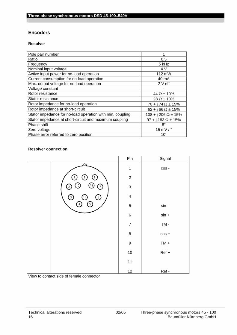
Three-phase synchronous motors DSD 45-100..540V
Technical alterations reserved 02/05 Three-phase synchronous motors 45 - 100 16 Baumüller Nürnberg GmbH
Encoders
Resolver Pole pair number 1 Ratio 0.5 Frequency 5 kHz Nominal input voltage 4 V Active input power for no-load operation 112 mW Current consumption for no-load operation 40 mA Max. output voltage for no-load operation 2 V eff Voltage constant - Rotor resistance 44 Ω ± 10% Stator resistance 28 Ω ± 10% Rotor impedance for no-load operation 70 + j 74 Ω ± 15% Rotor impedance at short-circuit 62 + j 66 Ω ± 15% Stator impedance for no-load operation with min. coupling 108 + j 206 Ω ± 15% Stator impedance at short-circuit and maximum coupling 97 + j 183 Ω ± 15% Phase shift 8° Zero voltage 15 mV / ° Phase error referred to zero position 10´
Resolver connection
Pin Signal
1
2
3
4
5
6
7
8
9
10
11
12
cos -
sin –
sin +
TM -
cos +
TM +
Ref +
Ref - View to contact side of female connector
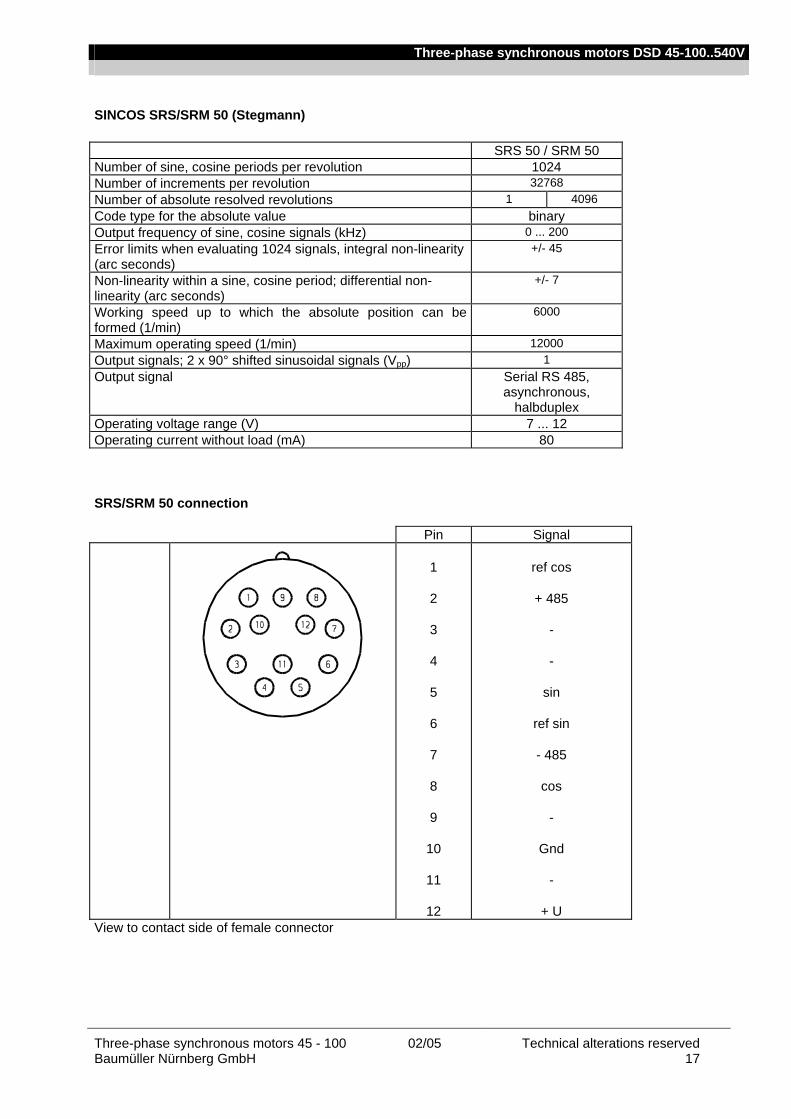
Three-phase synchronous motors DSD 45-100..540V
Three-phase synchronous motors 45 - 100 02/05 Technical alterations reserved Baumüller Nürnberg GmbH 17
SINCOS SRS/SRM 50 (Stegmann) SRS 50 / SRM 50 Number of sine, cosine periods per revolution 1024 Number of increments per revolution 32768 Number of absolute resolved revolutions 1 4096 Code type for the absolute value binary Output frequency of sine, cosine signals (kHz) 0 ... 200 Error limits when evaluating 1024 signals, integral non-linearity (arc seconds)
+/- 45
Non-linearity within a sine, cosine period; differential non-linearity (arc seconds)
+/- 7
Working speed up to which the absolute position can be formed (1/min)
6000
Maximum operating speed (1/min) 12000 Output signals; 2 x 90° shifted sinusoidal signals (Vpp) 1 Output signal Serial RS 485,
asynchronous, halbduplex
Operating voltage range (V) 7 ... 12 Operating current without load (mA) 80 SRS/SRM 50 connection
Pin Signal
1
2
3
4
5
6
7
8
9
10
11
12
ref cos
+ 485
-
-
sin
ref sin
- 485
cos
-
Gnd
-
+ U View to contact side of female connector
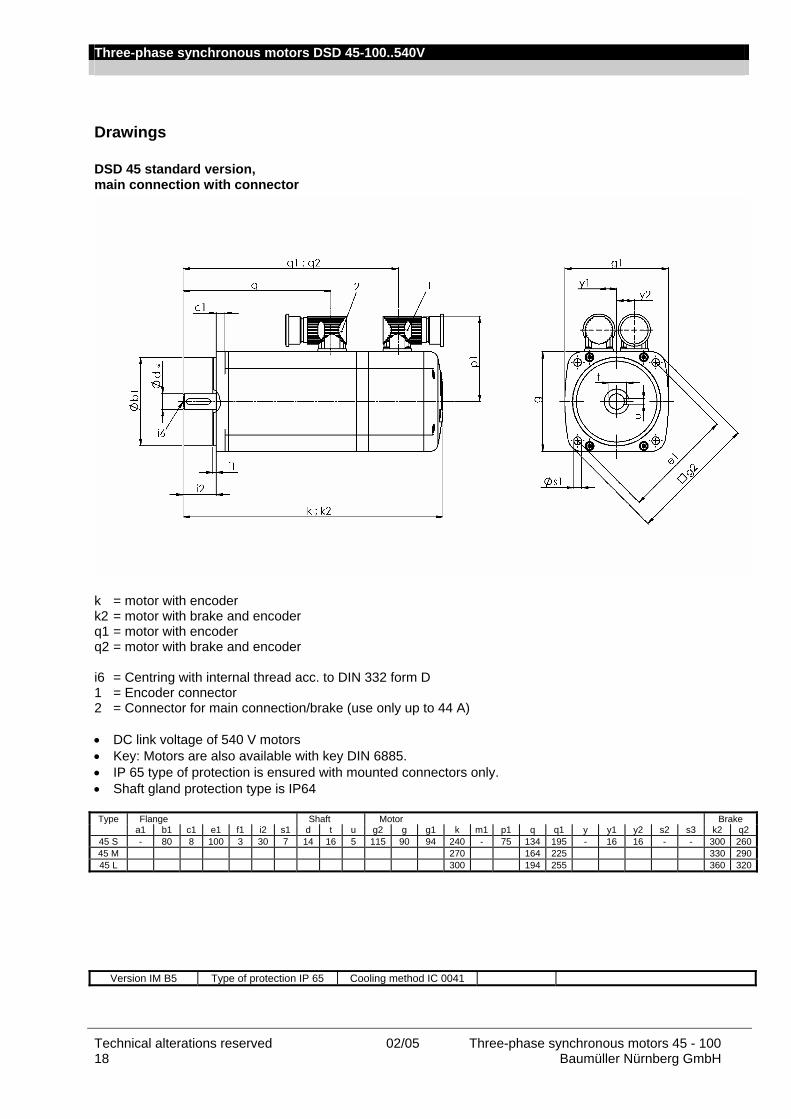
Three-phase synchronous motors DSD 45-100..540V
Technical alterations reserved 02/05 Three-phase synchronous motors 45 - 100 18 Baumüller Nürnberg GmbH
Drawings
DSD 45 standard version, main connection with connector
k = motor with encoder k2 = motor with brake and encoder q1 = motor with encoder q2 = motor with brake and encoder i6 = Centring with internal thread acc. to DIN 332 form D 1 = Encoder connector 2 = Connector for main connection/brake (use only up to 44 A) • DC link voltage of 540 V motors • Key: Motors are also available with key DIN 6885. • IP 65 type of protection is ensured with mounted connectors only. • Shaft gland protection type is IP64 Type Flange Shaft Motor Brake
a1 b1 c1 e1 f1 i2 s1 d t u g2 g g1 k m1 p1 q q1 y y1 y2 s2 s3 k2 q2 45 S - 80 8 100 3 30 7 14 16 5 115 90 94 240 - 75 134 195 - 16 16 - - 300 26045 M 270 164 225 330 29045 L 300 194 255 360 320
Version IM B5 Type of protection IP 65 Cooling method IC 0041
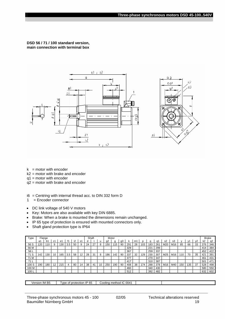
Three-phase synchronous motors DSD 45-100..540V
Three-phase synchronous motors 45 - 100 02/05 Technical alterations reserved Baumüller Nürnberg GmbH 19
DSD 56 / 71 / 100 standard version, main connection with terminal box
k = motor with encoder k2 = motor with brake and encoder q1 = motor with encoder q2 = motor with brake and encoder i6 = Centring with internal thread acc. to DIN 332 form D 1 = Encoder connector • DC link voltage of 540 V motors • Key: Motors are also available with key DIN 6885. • Brake: When a brake is mounted the dimensions remain unchanged. • IP 65 type of protection is ensured with mounted connectors only. • Shaft gland protection type is IP64 Type Flange Shaft Motor Brake
a1 b1 c1 e1 f1 i2 s1 d t u g2 g g3 k m1 p q q1 s2 s3 y y1 y2 k2 q2 56 S 120 110 9 130 3.5 50 9 24 27 8 150 115 90 291 28 103 183 261 M20 M16 85 66 33 376 34656 M 329 221 299 414 38456 L 367 259 337 452 42271 S 142 130 10 165 3.5 58 12 28 31 8 186 142 90 337 32 129 230 307 M25 M16 110 70 35 421 39171 M 377 270 347 461 43171 L 417 310 387 501 471
100 S 190 180 12 215 4 80 14 38 41 10 250 190 90 408 38 174 288 378 M16 M40 150 135 37 528 498100 M 460 340 430 580 550100 L 512 392 482 632 602
Version IM B5 Type of protection IP 65 Cooling method IC 0041

Three-phase synchronous motors DSD 45-100..540V
Technical alterations reserved 02/05 Three-phase synchronous motors 45 - 100 20 Baumüller Nürnberg GmbH
DSD 56 / 71 / 100 standard version, main connection with connector
k = motor with encoder k2 = motor with brake and encoder q1 = motor with encoder q2 = motor with brake and encoder i6 = Centring with internal thread acc. to DIN 332 form D 1 = Encoder connector 2 = Connector for main connection/brake (use only up to 44 A) • DC link voltage of 540 V motors • Key: Motors are also available with key DIN 6885. • IP 65 type of protection is ensured with mounted connectors only. • Shaft gland protection type is IP64 Type Flange Shaft Motor Brake
a1 b1 c1 e1 f1 i2 s1 d t u g2 g g3 k m1 p1 q q1 y y1 y2 s2 s3 k2 q2 56 S 120 110 9 130 3.5 50 9 24 27 8 150 115 90 291 28 123 183 261 - - - - - 376 34656 M 329 221 299 414 38456 L 367 259 337 452 42271 S 142 130 10 165 3.5 58 12 28 31 8 186 142 90 337 32 136 230 307 - - - - - 421 39171 M 377 270 347 461 43171 L 417 310 387 501 471
100 S 190 180 12 215 4 80 14 38 41 10 250 190 90 408 38 160 288 378 - - - - - 528 498100 M 460 340 430 580 550100 L 512 392 482 632 602
Version IM B5 Type of protection IP 65 Cooling method IC 0041

Three-phase synchronous motors DSD 45-100..540V
Three-phase synchronous motors 45 - 100 02/05 Technical alterations reserved Baumüller Nürnberg GmbH 21
DSD 56 / 71 / 100 standard version with fan, main connection with terminal box
k = motor with encoder k2 = motor with brake and encoder q1 = motor with encoder q2 = motor with brake and encoder i6 = Centring with internal thread acc. to DIN 332 form D 1 = Fan connector 2 = Encoder connector • DC link voltage of 540 V motors • Key: Motors are also available with key DIN 6885. • IP 65 type of protection is ensured with mounted connectors only. • Shaft gland protection type is IP64
Type Flange Shaft Motor Brake
a1 b1 c1 e1 f1 i2 s1 d t u g2 g k m1 p q q1 q3 y y1 y2 s2 s3 k2 q2 56 S 120 110 9 130 3.5 50 9 24 27 8 185 140 426 28 103 183 261 124 85 66 33 M20 M16 511 34656 M 464 221 299 549 38456 L 502 259 337 587 42271 S 142 130 10 165 3.5 58 12 28 31 8 230 180 466 32 129 230 307 124 110 70 35 M25 M16 550 39171 M 506 270 347 590 43171 L 546 310 387 630 471
100 S 190 180 12 215 4 80 14 38 41 10 275 215 537 38 174 288 378 124 150 135 37 M16 M40 657 498100 M 589 340 430 709 550100 L 641 392 482 761 602
Version IM B5 Type of protection IP 54 Cooling method IC 0641
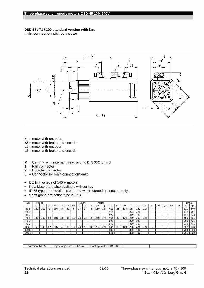
Three-phase synchronous motors DSD 45-100..540V
Technical alterations reserved 02/05 Three-phase synchronous motors 45 - 100 22 Baumüller Nürnberg GmbH
DSD 56 / 71 / 100 standard version with fan, main connection with connector
k = motor with encoder k2 = motor with brake and encoder q1 = motor with encoder q2 = motor with brake and encoder i6 = Centring with internal thread acc. to DIN 332 form D 1 = Fan connector 2 = Encoder connector 3 = Connector for main connection/brake • DC link voltage of 540 V motors • Key: Motors are also available without key • IP 65 type of protection is ensured with mounted connectors only. • Shaft gland protection type is IP64 Type Flange Shaft Motor Brake
a1 b1 c1 e1 f1 i2 s1 d t u g2 g k m1 p1 q q1 q3 y y1 y2 s2 s3 k2 q2 56 S 120 110 9 130 3.5 50 9 24 27 8 180 134 426 28 123 183 261 124 - - - - - 511 34656 M 464 221 299 549 38456 L 502 259 337 587 42271 S 142 130 10 165 3.5 58 12 28 31 8 230 178 466 32 136 230 307 124 - - - - - 550 39171 M 506 270 347 590 43171 L 546 310 387 630 471
100 S 190 180 12 215 4 80 14 38 41 10 284 224 537 38 160 288 378 124 - - - - - 657 498100 M 589 340 430 709 550100 L 641 392 482 761 602
Version IM B5 Type of protection IP 54 Cooling method IC 0641

Three-phase synchronous motors DSD 45-100..540V
Three-phase synchronous motors 45 - 100 02/05 Technical alterations reserved Baumüller Nürnberg GmbH 23
Motor cables General The motor cables are highly flexible trailing cables with overall shielding. They comply with the regulations VDE, UL and CSA. The control cables are integrated as star-quads integriert. When the sincos encoder is used the brake triggering and the connection of the thermal sensor are brought out via the main connector. The cables are particularly suitable for the optimum use of cable racks thanks to their low cross-section, low weight and non-impeding surface. They can thus be efficiently used in trailing chains. The overall shielding with an optical coverage of more than 85% makes it an EMC uncritical cable. The connector size is designed in accordance with the motor's standstill current I0. Technical data Technical description • Sheath resistance against media such as coolants, machine and gearbox oils • Abrasion resistance because of a special surface in cable racks and trailing chains • High-flexible, trailing cable • Sheath surface not blocking, satin-finish • Shield made of tinned copper braid with optical coverage of ≥ 85 % • Core insulation made of TPE or polyester, sheath material PUR holgene-free • Cable FCF-free and silicone-free • Behavior in case of fire: fire-inhibiting, halogene-free • Cable color in RAL 1028, melon yellow • Labelling with Baumüller sign, VDE, UL and CSA sign • Minimum bending radius for flexible use 12 x D Nominal voltage Uo/U 600 / 1000 V (power cores) U 24 V DC (control cores) Core lettering Power cores U, VV, WWW Colored control cable pairs as star-quads in red, white, black, yellow Assignment of pairs red – black (brake), white – yellow (temperature) Cable data
Cable cross-section Nominal current
[A]1)
Cable diameter [mm]
4×1.5 mm2 4×0.75 mm2 15 11.7 – 12.3 4×2.5 mm2 4×0.75 mm2 21 12.7 – 14.6 4×4 mm2 4×0.75 mm2 28 14.2 – 15.4 4×6 mm2 4×0.75 mm2 36 16.6 – 17.9 4×10 mm2 4×0.75 mm2 50 20.5 – 21.5 4×16 mm2 4×0.75 mm2 66 23.0 – 25.8
4×25 mm2 2×(2×1.5 mm2) 84 26.3 – 29.7 4×35 mm2 2×(2×1.5 mm2) 104 30.8 – 32.5
1) Current carrying capacity acc. to table 5 laying type C or E
(VDE 0113 / EN 60 204 Part 1 issue 1997) Ambient temperature 40°C
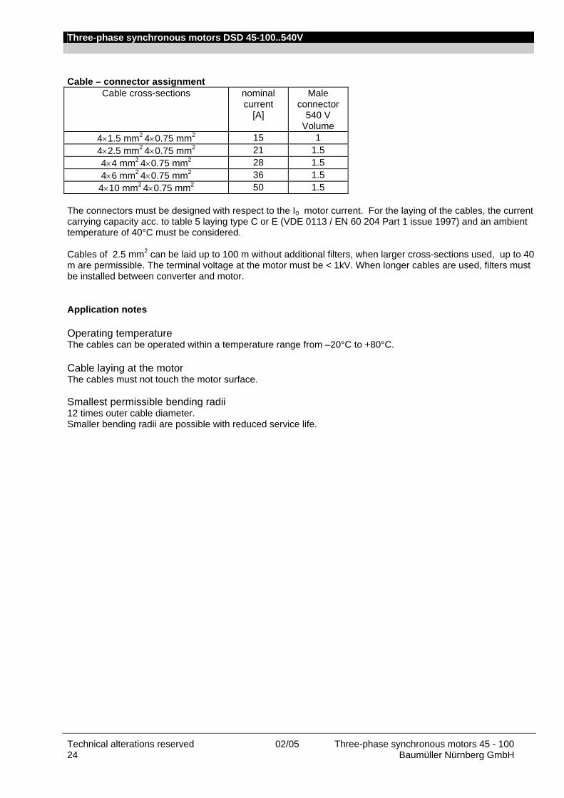
Three-phase synchronous motors DSD 45-100..540V
Technical alterations reserved 02/05 Three-phase synchronous motors 45 - 100 24 Baumüller Nürnberg GmbH
Cable – connector assignment
Cable cross-sections nominal current
[A]
Male connector
540 V Volume
4×1.5 mm2 4×0.75 mm2 15 1 4×2.5 mm2 4×0.75 mm2 21 1.5 4×4 mm2 4×0.75 mm2 28 1.5 4×6 mm2 4×0.75 mm2 36 1.5 4×10 mm2 4×0.75 mm2 50 1.5
The connectors must be designed with respect to the I0 motor current. For the laying of the cables, the current carrying capacity acc. to table 5 laying type C or E (VDE 0113 / EN 60 204 Part 1 issue 1997) and an ambient temperature of 40°C must be considered. Cables of 2.5 mm2 can be laid up to 100 m without additional filters, when larger cross-sections used, up to 40 m are permissible. The terminal voltage at the motor must be < 1kV. When longer cables are used, filters must be installed between converter and motor. Application notes Operating temperature The cables can be operated within a temperature range from –20°C to +80°C. Cable laying at the motor The cables must not touch the motor surface. Smallest permissible bending radii 12 times outer cable diameter. Smaller bending radii are possible with reduced service life.
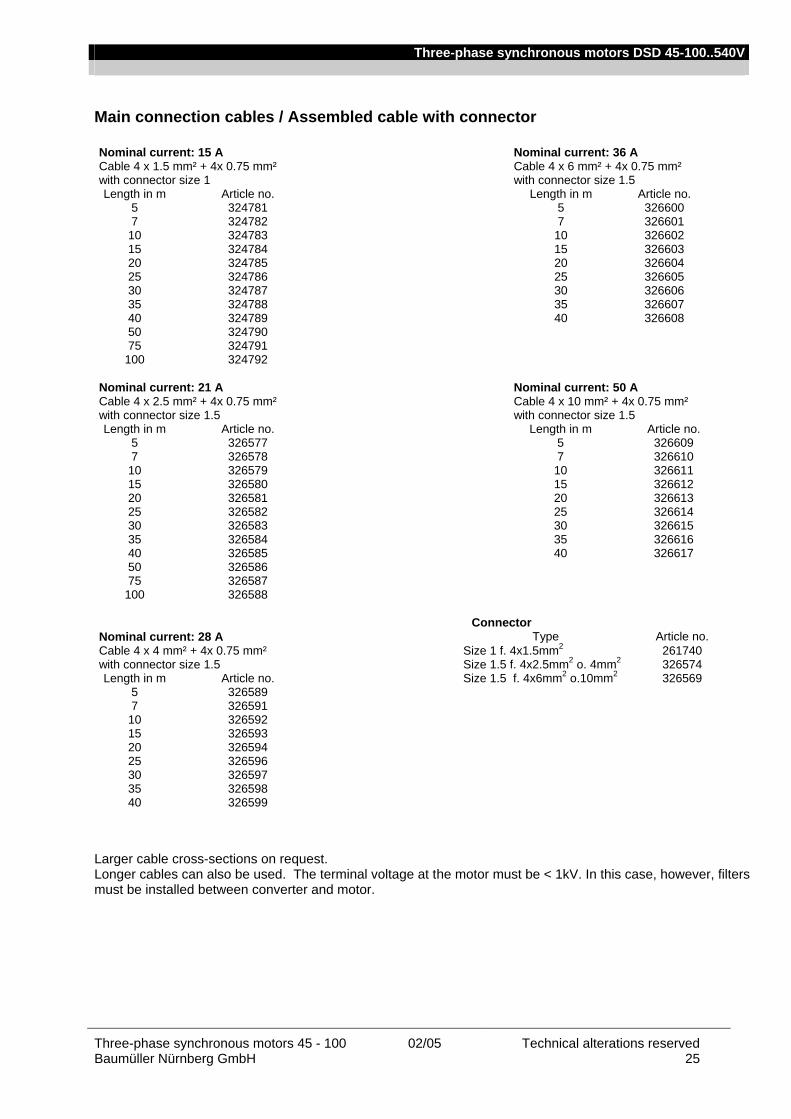
Three-phase synchronous motors DSD 45-100..540V
Three-phase synchronous motors 45 - 100 02/05 Technical alterations reserved Baumüller Nürnberg GmbH 25
Main connection cables / Assembled cable with connector Nominal current: 15 A Nominal current: 36 A Cable 4 x 1.5 mm² + 4x 0.75 mm² Cable 4 x 6 mm² + 4x 0.75 mm² with connector size 1 with connector size 1.5 Length in m Article no. Length in m Article no.
5 324781 5 326600 7 324782 7 326601 10 324783 10 326602 15 324784 15 326603 20 324785 20 326604 25 324786 25 326605 30 324787 30 326606 35 324788 35 326607 40 324789 40 326608 50 324790 75 324791
100 324792 Nominal current: 21 A Nominal current: 50 A Cable 4 x 2.5 mm² + 4x 0.75 mm² Cable 4 x 10 mm² + 4x 0.75 mm² with connector size 1.5 with connector size 1.5 Length in m Article no. Length in m Article no.
5 326577 5 326609 7 326578 7 326610 10 326579 10 326611 15 326580 15 326612 20 326581 20 326613 25 326582 25 326614 30 326583 30 326615 35 326584 35 326616 40 326585 40 326617 50 326586 75 326587
100 326588 Connector Nominal current: 28 A Type Article no. Cable 4 x 4 mm² + 4x 0.75 mm² Size 1 f. 4x1.5mm2 261740 with connector size 1.5 Size 1.5 f. 4x2.5mm2 o. 4mm2 326574 Length in m Article no. Size 1.5 f. 4x6mm2 o.10mm2 326569
5 326589 7 326591 10 326592 15 326593 20 326594 25 326596 30 326597 35 326598 40 326599
Larger cable cross-sections on request. Longer cables can also be used. The terminal voltage at the motor must be < 1kV. In this case, however, filters must be installed between converter and motor.
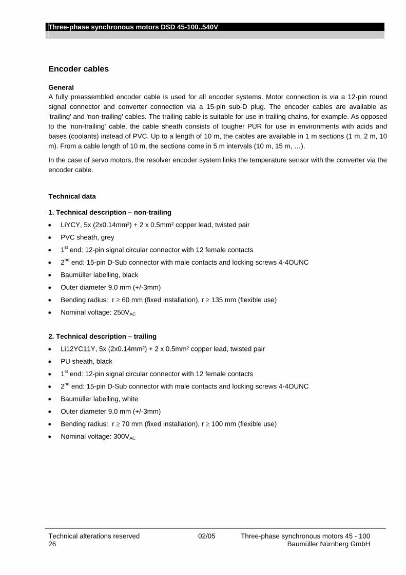
Three-phase synchronous motors DSD 45-100..540V
Technical alterations reserved 02/05 Three-phase synchronous motors 45 - 100 26 Baumüller Nürnberg GmbH
Encoder cables General A fully preassembled encoder cable is used for all encoder systems. Motor connection is via a 12-pin round signal connector and converter connection via a 15-pin sub-D plug. The encoder cables are available as 'trailing' and 'non-trailing' cables. The trailing cable is suitable for use in trailing chains, for example. As opposed to the 'non-trailing' cable, the cable sheath consists of tougher PUR for use in environments with acids and bases (coolants) instead of PVC. Up to a length of 10 m, the cables are available in 1 m sections (1 m, 2 m, 10 m). From a cable length of 10 m, the sections come in 5 m intervals (10 m, 15 m, …).
In the case of servo motors, the resolver encoder system links the temperature sensor with the converter via the encoder cable.
Technical data 1. Technical description – non-trailing
• LiYCY, 5x (2x0.14mm²) + 2 x 0.5mm² copper lead, twisted pair
• PVC sheath, grey
• 1st end: 12-pin signal circular connector with 12 female contacts
• 2nd end: 15-pin D-Sub connector with male contacts and locking screws 4-4OUNC
• Baumüller labelling, black
• Outer diameter 9.0 mm (+/-3mm)
• Bending radius: r ≥ 60 mm (fixed installation), r ≥ 135 mm (flexible use)
• Nominal voltage: 250VAC 2. Technical description – trailing
• Li12YC11Y, 5x (2x0.14mm²) + 2 x 0.5mm² copper lead, twisted pair
• PU sheath, black
• 1st end: 12-pin signal circular connector with 12 female contacts
• 2nd end: 15-pin D-Sub connector with male contacts and locking screws 4-4OUNC
• Baumüller labelling, white
• Outer diameter 9.0 mm (+/-3mm)
• Bending radius: r ≥ 70 mm (fixed installation), r ≥ 100 mm (flexible use)
• Nominal voltage: 300VAC
Three-phase synchronous motors DSD 45-100..540V
Three-phase synchronous motors 45 - 100 02/05 Technical alterations reserved Baumüller Nürnberg GmbH 27
Application notes • Operating temperature trailing non-trailing Limit temperature at the surface at the surface
no / few movements -40 °C to +80 °C - 30 °C to +80 °C
continuous movements - 30 °C to +80 °C -5 °C to + 70 °C • Cable laying at the motor The cables must not touch the motor surface. Ordering data Encoder cables / preassembled cables with connector Encoder cable Non-trailing,assembled Trailing, assembled Cable 5 x (2x014mm2) + 2 x 0.5 mm² with connector
Cable 5 x (2x014mm2) + 2 x 0.5 mm² with connector
Length in m Article no. Length in m Article no.
1 243601 3 246658 2 211338 4 243379 3 219333 5 239540 4 231166 6 242954 5 209879 8 239541 6 220197 10 239542 7 216455 15 239543 8 220429 20 239544 10 210052 25 239545 15 215716 30 239546 20 218568 35 239547 25 218569 40 240520 30 217094 45 240521 35 216444 50 240522 40 217095 55 244033 45 217567 60 245484 50 217568 55 217569 60 217570 Encoder
connector Article no.
70 232088 Encoder connector
201833
Commissioning and maintenance instructions Please contact us for our commissioning and maintenance instructions for motor commissioning.

Three-phase synchronous motors DSD 45-100..540V
Technical alterations reserved 02/05 Three-phase synchronous motors 45 - 100 28 Baumüller Nürnberg GmbH
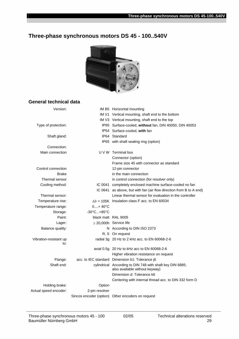
Three-phase synchronous motors DS 45-100..540V
Three-phase synchronous motors 45 - 100 02/05 Technical alterations reserved Baumüller Nürnberg GmbH 29
Three-phase synchronous motors DS 45 - 100..540V
General technical data Version: IM B5 Horizontal mounting
IM V1 Vertical mounting, shaft end to the bottom IM V3 Vertical mounting, shaft end to the top
Type of protection: IP65 Surface-cooled, without fan, DIN 40050, DIN 40053 IP54 Surface-cooled, with fan
Shaft gland: IP64 Standard IP65 with shaft sealing ring (option)
Connection: Main connection U V W Terminal box
Connector (option) Frame size 45 with connector as standard
Control connection 12-pin connector Brake in the main connection
Thermal sensor in control connection (for resolver only) Cooling method: IC 0041 completely enclosed machine surface-cooled no fan
IC 0641 as above, but with fan (air flow direction from B to A end) Thermal sensor: Linear thermal sensor for evaluation in the controller
Temperature rise: ∆ϑ = 105K Insulation class F acc. to EN 60034 Temperature range: 0....+ 40°C
Storage: -30°C...+85°C Paint: black matt RAL 9005 Lager: ≥ 20,000h Service life
Balance quality: N According to DIN ISO 2373 R, S On request
Vibration-resistant up to:
radial 3g 20 Hz to 2 kHz acc. to EN 60068-2-6
axial 0.5g 20 Hz to kHz acc to EN 60068-2-6 Higher vibration resistance on request
Flange: acc. to IEC standard Dimension b1: Tolerance j6 Shaft end: cylindrical According to DIN 748 with shaft key DIN 6885;
also available without keyway) Dimension d: Tolerance k6 Centering with internal thread acc. to DIN 332 form D
Holding brake: Option Actual speed encoder: 2-pin resolver
Sincos encoder (option) Other encoders on request
Three-phase synchronous motors DS 45-100..540V
Technical alterations reserved 02/05 Three-phase synchronous motors 45 - 100 30 Baumüller Nürnberg GmbH
Ratings definition The ratings (torques) listed in the table apply to continuous operation (S1) with nominal speed at a maximum ambient temperature of 40°C with the machine being installed below 1000m a.m.s.l.
If motors are to be operated in an ambient temperature of more than 40 °C or altitudes above 1000 m a.m.s.l., the required list nominal power PL (list torque Mn) results from the product of the factors k1, k2 specified in the table and the required power P (torque M).
Ambient temperature 40 °C 45°C 50 °C 55°C 60°C
Correction factor k1
1 1.06 1.13 1.22 1.34
Altitude a.m.s.l. up to
1.000m
2.000m
3.000m
4.000m
5.000m
Correction factor k2
1 1.07 1.16 1.27 1.55
For ambient temperatures above 40 °C and enclosed installation of motors, it is absolutely necessary to contact the manufacturer, because design changes may be necessary. If, with increasing site altitude above 1000 m, the ambient temperature decreases by approx. 10 °C per 1000 m increase in altitude, no power correction is necessary.
Winding isolation and temperature rise All machines of this series are designed in insulation class F according to EN 60034 for a permissible winding temperature of 105 K at a room temperature of up to 40 °C. The insulation is resistant against gases and vapours of combustible materials and it meets the requirements placed on a moisture-proof and tropical insulation.
A special insulation that can be obtained for an extra charge is necessary if concentrated acid vapours and metallic powders occur, with a permanent relative air humidity of more than 80% and as protection against termite and mould fungus attacks.
In the case of converters with a DC link voltage > 500 V, the cables between the converter and the motor must not be longer than 20 meters. For longer cables, additional measures (e.g. motor filters) must be provided. The maximum permissible terminal voltage is 1000 V.
Explanation of the motor data M0, I0 Nominal torque (Nm) with nominal current (A) with speed >= 1 min-1 without time limit, I0 is the r.m.s. value MN, IN Nominal torque (Nm) with Nominal current (A) with nominal speed nN in continuous operation (S1);TA = 40 °C* MS3-40%, IS3-40% Torque and speed for intermittent operation S3-40% duty time, cycle of 10 minutes nN Nominal speed ( min-1 ) kE Motor e.m.f. referred to 1000 min-1 (voltage constant) kT Torque constant: kT x I0 = M0 + MR (intrinsic moment) kD Torque loss referred to 1000 min-1 (eddy-current loss) MR Bearing friction including hysteresis torque m Weight in kg J Rotor inertia incl. resolver without holding brake (kg cm²) The specified ratings / torques at nominal speed are achieved with a chopping frequency of ≥ 4 kHz in the power unit of the converter. A chopping frequency of > 6 kHz is recommended. * A part of the loss in the motor is dissipated via the flange. The temperature at the flange must not exceed 65°C!
Basic calculation Valid under the prerequisite that torque and speed are within the speed-torque characteristic. Motor current I for speed n and torque M
[ ]Ak
n/10MM I T
3DR ∗++
=k
-
Torque M for any speed and current I
[ ]Nm10
nMI =M 3DRT )( ∗+−∗ kk
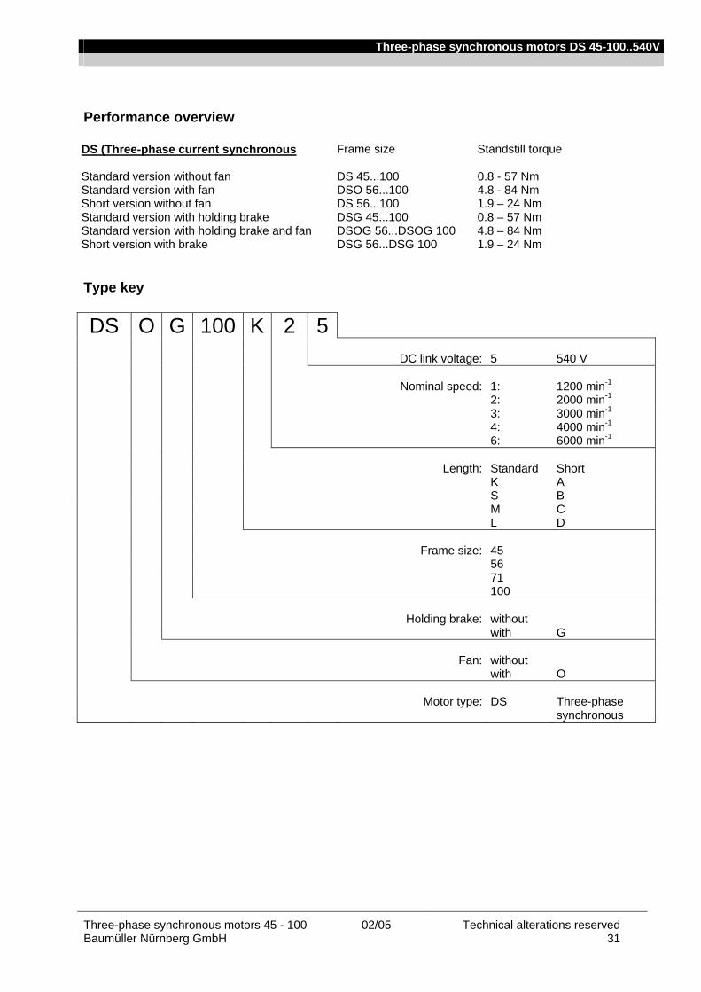
Three-phase synchronous motors DS 45-100..540V
Three-phase synchronous motors 45 - 100 02/05 Technical alterations reserved Baumüller Nürnberg GmbH 31
Performance overview DS (Three-phase current synchronous Frame size Standstill torque Standard version without fan DS 45...100 0.8 - 57 Nm Standard version with fan DSO 56...100 4.8 - 84 Nm Short version without fan DS 56...100 1.9 – 24 Nm Standard version with holding brake DSG 45...100 0.8 – 57 Nm Standard version with holding brake and fan DSOG 56...DSOG 100 4.8 – 84 Nm Short version with brake DSG 56...DSG 100 1.9 – 24 Nm
Type key
DS O G 100 K 2 5 DC link voltage: 5 540 V Nominal speed: 1: 1200 min-1 2: 2000 min-1 3: 3000 min-1 4: 4000 min-1 6: 6000 min-1 Length: Standard Short K A S B M C L D Frame size: 45 56 71 100 Holding brake: without with G Fan: without with O Motor type: DS Three-phase
synchronous
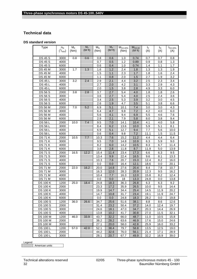
Three-phase synchronous motors DS 45-100..540V
Technical alterations reserved 02/05 Three-phase synchronous motors 45 - 100 32 Baumüller Nürnberg GmbH
Technical data
DS standard version Type nN
(1/min) M0
(Nm)
M0 (lbf ft)
MN (Nm)
MN (lbf ft)
MS3-40%(Nm)
MS3-40 (lbf ft)
I0 (A)
IN (A)
IS3-40%(A)
DS 45 S 3000 0.8 0.6 0.8 0.6 1.0 0.74 0.7 0.7 0.8 DS 45 S 4000 0.7 0.5 1.2 0.89 0.9 0.8 1.3 DS 45 S 6000 0.6 0.4 1.0 0.74 1.4 1.1 1.7 DS 45 M 3000 1.7 1.3 1.6 1.2 2.4 1.8 1.3 1.3 1.9 DS 45 M 4000 1.5 1.1 2.3 1.7 1.8 1.6 2.4 DS 45 M 6000 1.1 0.8 2.0 1.5 2.7 1.9 3.2 DS 45 L 3000 3.2 2.4 2.9 2.1 4.4 3.2 2.5 2.3 3.4 DS 45 L 4000 2.7 2.0 4.2 3.1 3.3 2.9 4.3 DS 45 L 6000 2.0 1.5 3.8 2.8 4.9 3.3 6.0 DS 56 S 2000 3.8 2.8 3.7 2.7 5.4 4.0 1.8 1.8 2.6 DS 56 S 3000 3.6 2.7 5.4 4.0 2.5 2.4 3.6 DS 56 S 4000 3.4 2.5 5.3 3.9 3.2 3.0 4.5 DS 56 S 6000 2.6 1.9 4.7 3.5 5.1 3.8 6.6 DS 56 M 2000 7.0 5.2 6.9 5.1 10.1 7.4 3.0 3.0 4.3 DS 56 M 3000 6.4 4.7 9.8 7.2 4.2 4.0 6.0 DS 56 M 4000 5.6 4.1 9.4 6.9 5.5 4.6 7.6 DS 56 M 6000 2.9 2.1 7.9 5.8 8.0 3.8 9.4 DS 56 L 2000 10.0 7.4 9.5 7.0 14.1 10.4 4.1 4.0 5.8 DS 56 L 3000 8.4 6.2 13.6 10.0 5.9 5.1 8.1 DS 56 L 4000 6.9 5.1 12.7 9.4 7.7 5.6 10.0 DS 56 L 6000 0.6 0.4 9.8 7.2 11.1 1.5 11.5 DS 71 K 2000 10.5 7.7 10.3 7.6 15.2 11.2 4.4 4.4 6.4 DS 71 K 3000 9.5 7.0 14.8 10.9 6.3 5.9 9.0 DS 71 K 4000 8.2 6.0 14.2 10.5 8.3 6.7 11.4 DS 71 K 6000 3.8 2.8 11.8 8.7 11.9 5.0 13.9 DS 71 S 2000 16.5 12.2 15.4 11.4 23.4 17.3 6.6 6.3 9.5 DS 71 S 3000 13.4 9.9 22.4 16.5 9.6 8.1 13.3 DS 71 S 4000 10.3 7.6 20.7 15.3 12.4 8.2 16.0 DS 71 S 6000 0.0 0.0 16.4 12.1 18.6 0.0 20.1 DS 71 M 2000 22.0 16.2 20.0 14.8 27.6 20.4 8.4 7.8 10.7 DS 71 M 3000 16.3 12.0 28.3 20.9 12.3 9.5 16.2 DS 71 M 4000 10.4 7.7 16.3 12.0 15.8 8.2 12.4 DS 71 M 6000 0.0 0.0 18 13.3 24.8 0.0 13.8 DS 100 K 1200 25.0 18.4 24.8 18.3 36.3 26.8 6.3 6.3 9.2 DS 100 K 2000 23.3 17.2 35.9 26.5 10.0 9.5 14.4 DS 100 K 3000 19.9 14.7 34.4 25.4 14.5 11.9 20.2 DS 100 K 4000 14.7 10.8 31.7 23.4 19.1 11.9 24.7 DS 100 K 6000 0.0 0.0 24.8 18.3 28.2 0.0 19.8 DS 100 S 1200 36.0 26.6 34.7 25.6 51.6 38.1 8.8 8.6 12.6 DS 100 S 2000 31.4 23.2 50.4 37.2 14.0 12.4 19.7 DS 100 S 3000 24.6 18.1 47.0 34.7 20.3 14.4 26.9 DS 100 S 4000 13.8 10.2 41.7 30.8 27.0 11.5 32.1 DS 100 M 1200 46.0 33.9 43.7 32.2 66.0 48.7 11.0 10.5 15.8 DS 100 M 2000 38.2 28.2 63.6 46.9 17.6 15.0 24.6 DS 100 M 3000 27.1 20.0 58.0 42.8 25.9 16.0 33.2 DS 100 L 1200 57.0 42.0 52.1 38.4 79.7 58.8 13.5 12.5 19.0 DS 100 L 2000 44.2 32.6 76.0 56.1 21.4 17.1 28.9 DS 100 L 3000 28.1 20.7 67.7 49.9 32.2 16.9 39.0
Legend American units
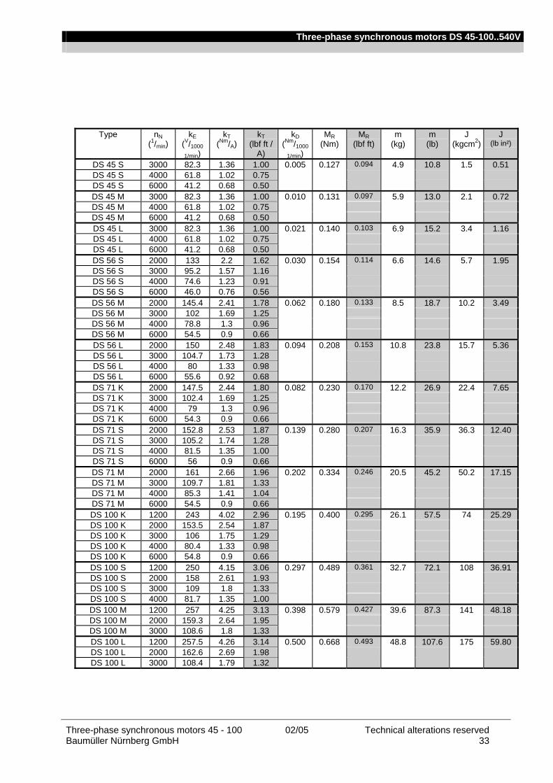
Three-phase synchronous motors DS 45-100..540V
Three-phase synchronous motors 45 - 100 02/05 Technical alterations reserved Baumüller Nürnberg GmbH 33
Type nN (1/min)
kE (V/1000
1/min)
kT (Nm/A)
kT (lbf ft /
A)
kD (Nm/1000
1/min)
MR (Nm)
MR (lbf ft)
m (kg)
m (lb)
J (kgcm2)
J (lb in²)
DS 45 S 3000 82.3 1.36 1.00 0.005 0.127 0.094 4.9 10.8 1.5 0.51 DS 45 S 4000 61.8 1.02 0.75 DS 45 S 6000 41.2 0.68 0.50 DS 45 M 3000 82.3 1.36 1.00 0.010 0.131 0.097 5.9 13.0 2.1 0.72 DS 45 M 4000 61.8 1.02 0.75 DS 45 M 6000 41.2 0.68 0.50 DS 45 L 3000 82.3 1.36 1.00 0.021 0.140 0.103 6.9 15.2 3.4 1.16 DS 45 L 4000 61.8 1.02 0.75 DS 45 L 6000 41.2 0.68 0.50 DS 56 S 2000 133 2.2 1.62 0.030 0.154 0.114 6.6 14.6 5.7 1.95 DS 56 S 3000 95.2 1.57 1.16 DS 56 S 4000 74.6 1.23 0.91 DS 56 S 6000 46.0 0.76 0.56 DS 56 M 2000 145.4 2.41 1.78 0.062 0.180 0.133 8.5 18.7 10.2 3.49 DS 56 M 3000 102 1.69 1.25 DS 56 M 4000 78.8 1.3 0.96 DS 56 M 6000 54.5 0.9 0.66 DS 56 L 2000 150 2.48 1.83 0.094 0.208 0.153 10.8 23.8 15.7 5.36 DS 56 L 3000 104.7 1.73 1.28 DS 56 L 4000 80 1.33 0.98 DS 56 L 6000 55.6 0.92 0.68 DS 71 K 2000 147.5 2.44 1.80 0.082 0.230 0.170 12.2 26.9 22.4 7.65 DS 71 K 3000 102.4 1.69 1.25 DS 71 K 4000 79 1.3 0.96 DS 71 K 6000 54.3 0.9 0.66 DS 71 S 2000 152.8 2.53 1.87 0.139 0.280 0.207 16.3 35.9 36.3 12.40 DS 71 S 3000 105.2 1.74 1.28 DS 71 S 4000 81.5 1.35 1.00 DS 71 S 6000 56 0.9 0.66 DS 71 M 2000 161 2.66 1.96 0.202 0.334 0.246 20.5 45.2 50.2 17.15 DS 71 M 3000 109.7 1.81 1.33 DS 71 M 4000 85.3 1.41 1.04 DS 71 M 6000 54.5 0.9 0.66 DS 100 K 1200 243 4.02 2.96 0.195 0.400 0.295 26.1 57.5 74 25.29 DS 100 K 2000 153.5 2.54 1.87 DS 100 K 3000 106 1.75 1.29 DS 100 K 4000 80.4 1.33 0.98 DS 100 K 6000 54.8 0.9 0.66 DS 100 S 1200 250 4.15 3.06 0.297 0.489 0.361 32.7 72.1 108 36.91 DS 100 S 2000 158 2.61 1.93 DS 100 S 3000 109 1.8 1.33 DS 100 S 4000 81.7 1.35 1.00 DS 100 M 1200 257 4.25 3.13 0.398 0.579 0.427 39.6 87.3 141 48.18 DS 100 M 2000 159.3 2.64 1.95 DS 100 M 3000 108.6 1.8 1.33 DS 100 L 1200 257.5 4.26 3.14 0.500 0.668 0.493 48.8 107.6 175 59.80 DS 100 L 2000 162.6 2.69 1.98 DS 100 L 3000 108.4 1.79 1.32

Three-phase synchronous motors DS 45-100..540V
Technical alterations reserved 02/05 Three-phase synchronous motors 45 - 100 34 Baumüller Nürnberg GmbH
DS standard version with fan
Type nN (1/min)
M0 (Nm)
M0 (lbf ft)
MN (Nm)
MN (lbf ft)
MS3-40%(Nm)
MS3-40% (lbf ft)
I0 (A)
IN (A)
IS3-40%(A)
DSO 56 S 2000 4.8 3.5 4.8 3.5 5.5 4.1 2.2 2.3 2.6 DSO 56 S 3000 4.8 3.5 5.3 3.9 3.1 3.2 3.5 DSO 56 S 4000 4.7 3.5 5.2 3.8 4.0 4.1 4.5 DSO 56 S 6000 4.2 3.1 4.7 3.5 5.9 5.4 6.0 DSO 56 M 2000 9.2 6.8 9.1 6.7 10.3 7.6 3.9 3.9 4.4 DSO 56 M 3000 9.0 6.6 10.1 7.4 5.5 5.5 6.2 DSO 56 M 4000 8.6 6.3 9.6 7.1 7.2 7.0 7.7 DSO 56 M 6000 7.3 5.4 8.5 6.3 10.5 8.8 10.2 DSO 56 L 2000 13.2 9.7 13.1 9.7 14.5 10.7 5.4 5.4 6.0 DSO 56 L 3000 12.5 9.2 14.2 10.5 7.7 7.5 8.5 DSO 56 L 4000 11.7 8.6 13.1 9.7 10.1 9.2 10.3 DSO 56 L 6000 9.2 6.8 11.5 8.5 14.7 10.9 13.4 DSO 71 K 2000 14.0 10.3 13.9 10.3 16.3 12.0 5.8 5.8 6.8 DSO 71 K 3000 13.7 10.1 15.9 11.7 8.4 8.4 9.7 DSO 71 K 4000 13.4 9.9 15.0 11.1 11.0 10.8 12.0 DSO 71 K 6000 11.8 8.7 13.5 10.0 16.0 14.1 16.0 DSO 71 S 2000 23.0 17.0 22.8 16.8 25.6 18.9 9.2 9.2 10.3 DSO 71 S 3000 21.9 16.2 24.5 18.1 13.4 13.0 14.5 DSO 71 S 4000 20.5 15.1 23.4 17.3 17.3 15.8 18.0 DSO 71 S 6000 16.3 12.0 18.1 13.3 25.2 18.9 20.8 DSO 71 M 2000 31.0 22.9 30.2 22.3 33.4 24.6 12.1 11.9 13.2 DSO 71 M 3000 28.6 21.1 33.5 24.7 17.8 16.8 19.6 DSO 71 M 4000 26.2 19.3 29.4 21.7 22.9 20.0 22.3 DSO 71 M 6000 18.8 13.9 25.0 18.4 35.0 22.7 29.6 DSO 100 K 1200 36.0 26.6 35.9 26.5 41.5 30.6 9.0 9.1 10.5 DSO 100 K 2000 35.6 26.3 41.3 30.5 14.3 14.3 16.6 DSO 100 K 3000 35.1 25.9 40.4 29.8 20.9 20.7 23.7 DSO 100 K 4000 33.5 24.7 37.7 27.8 27.5 26.2 29.4 DSO 100 K 6000 27.6 20.4 32.2 23.7 40.5 32.5 37.6 DSO 100 S 1200 53.0 39.1 52.8 38.9 59.0 43.5 12.9 12.9 14.4 DSO 100 S 2000 52.4 38.6 60.1 44.3 20.5 20.5 23.4 DSO 100 S 3000 50.1 37.0 57.2 42.2 29.8 28.7 32.6 DSO 100 S 4000 46.1 34.0 51.2 37.8 39.8 35.5 39.3 DSO 100 M 1200 69.0 50.9 68.8 50.7 77.9 57.5 16.3 16.4 18.6 DSO 100 M 2000 67.5 49.8 75.4 55.6 26.4 26.1 29.1 DSO 100 M 3000 63.1 46.5 69.9 51.6 38.7 36.1 39.9 DSO 100 L 1200 84.0 62.0 83.8 61.8 96.8 71.4 19.9 19.9 23.0 DSO 100 L 2000 81.4 60.0 91.8 67.7 31.5 30.9 34.7 DSO 100 L 3000 75.0 55.3 82.9 61.1 47.4 43.2 47.6
Legend American units
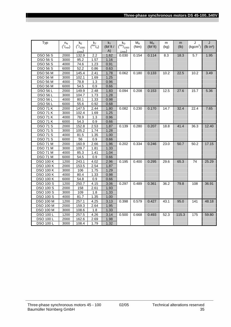
Three-phase synchronous motors DS 45-100..540V
Three-phase synchronous motors 45 - 100 02/05 Technical alterations reserved Baumüller Nürnberg GmbH 35
Typ nN (1/min)
kE (V/1000
1/min)
kT (Nm/A)
kT (lbf ft /
A)
kD (Nm/1000
1/min)
MR (Nm)
MR (lbf ft)
m (kg)
m (lb)
J (kgcm2)
J (lb in²)
DSO 56 S 2000 132.9 2.2 1.62 0.030 0.154 0.114 8.3 18.3 5.7 1.95 DSO 56 S 3000 95.2 1.57 1.16 DSO 56 S 4000 74.6 1.23 0.91 DSO 56 S 6000 52.2 0.86 0.63 DSO 56 M 2000 145.4 2.41 1.78 0.062 0.180 0.133 10.2 22.5 10.2 3.49 DSO 56 M 3000 102.1 1.69 1.25 DSO 56 M 4000 78.8 1.3 0.96 DSO 56 M 6000 54.5 0.9 0.66 DSO 56 L 2000 149.9 2.48 1.83 0.094 0.208 0.153 12.5 27.6 15.7 5.36 DSO 56 L 3000 104.7 1.73 1.28 DSO 56 L 4000 80.1 1.33 0.98 DSO 56 L 6000 55.6 0.92 0.68 DSO 71 K 2000 147.5 2.44 1.80 0.082 0.230 0.170 14.7 32.4 22.4 7.65 DSO 71 K 3000 102.4 1.69 1.25 DSO 71 K 4000 78.9 1.3 0.96 DSO 71 K 6000 54.3 0.9 0.66 DSO 71 S 2000 152.8 2.53 1.87 0.139 0.280 0.207 18.8 41.4 36.3 12.40 DSO 71 S 3000 105.2 1.74 1.28 DSO 71 S 4000 81.5 1.35 1.00 DSO 71 S 6000 56 0.9 0.66 DSO 71 M 2000 160.9 2.66 1.96 0.202 0.334 0.246 23.0 50.7 50.2 17.15 DSO 71 M 3000 109.7 1.81 1.33 DSO 71 M 4000 85.3 1.41 1.04 DSO 71 M 6000 54.5 0.9 0.66 DSO 100 K 1200 243.1 4.02 2.96 0.195 0.400 0.295 29.6 65.3 74 25.29 DSO 100 K 2000 153.5 2.54 1.87 DSO 100 K 3000 106 1.75 1.29 DSO 100 K 4000 80.4 1.33 0.98 DSO 100 K 6000 54.8 0.9 0.66 DSO 100 S 1200 250.7 4.15 3.06 0.297 0.489 0.361 36.2 79.8 108 36.91 DSO 100 S 2000 158 2.61 1.93 DSO 100 S 3000 109 1.8 1.33 DSO 100 S 4000 81.7 1.35 1.00 DSO 100 M 1200 257.1 4.25 3.13 0.398 0.579 0.427 43.1 95.0 141 48.18 DSO 100 M 2000 159.3 2.64 1.95 DSO 100 M 3000 108.6 1.8 1.33 DSO 100 L 1200 257.5 4.26 3.14 0.500 0.668 0.493 52.3 115.3 175 59.80 DSO 100 L 2000 162.6 2.69 1.98 DSO 100 L 3000 108.4 1.79 1.32
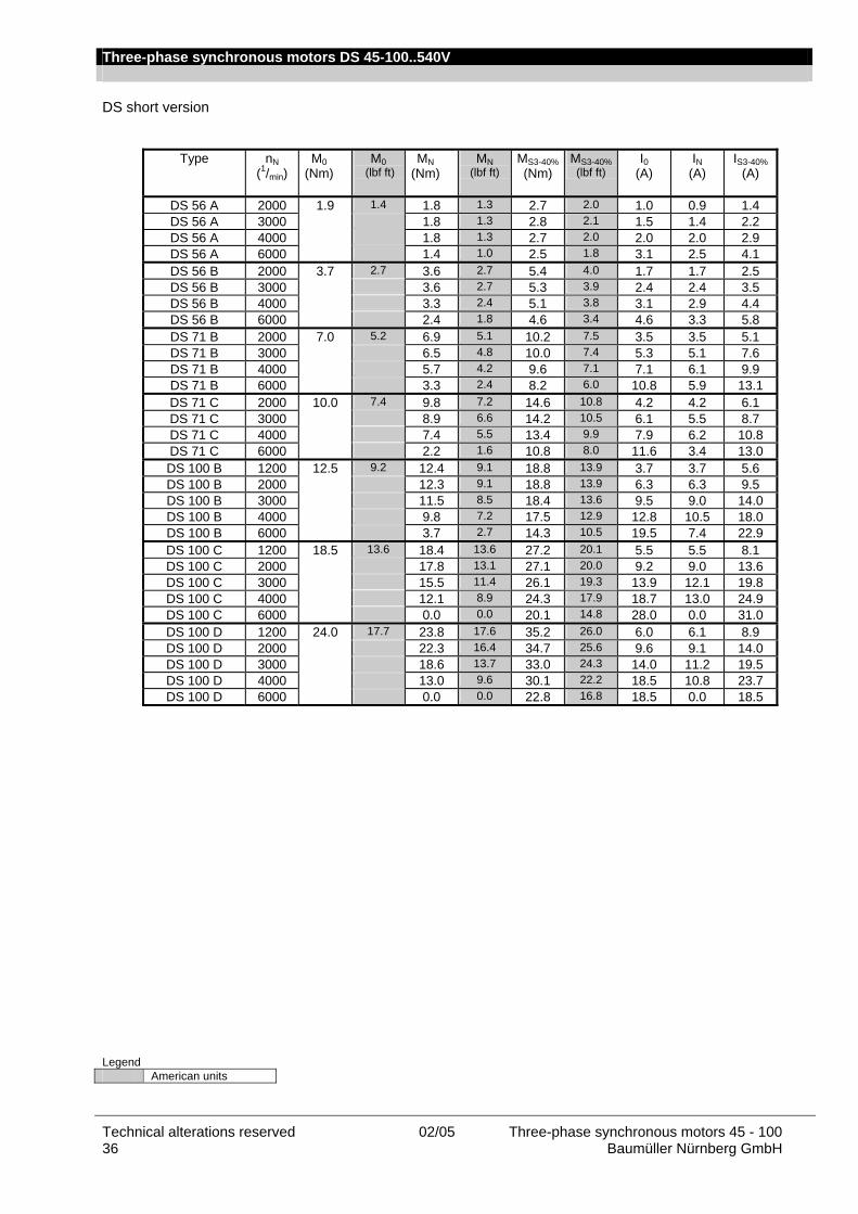
Three-phase synchronous motors DS 45-100..540V
Technical alterations reserved 02/05 Three-phase synchronous motors 45 - 100 36 Baumüller Nürnberg GmbH
DS short version
Type nN (1/min)
M0 (Nm)
M0 (lbf ft)
MN (Nm)
MN (lbf ft)
MS3-40%(Nm)
MS3-40% (lbf ft)
I0 (A)
IN (A)
IS3-40%(A)
DS 56 A 2000 1.9 1.4 1.8 1.3 2.7 2.0 1.0 0.9 1.4 DS 56 A 3000 1.8 1.3 2.8 2.1 1.5 1.4 2.2 DS 56 A 4000 1.8 1.3 2.7 2.0 2.0 2.0 2.9 DS 56 A 6000 1.4 1.0 2.5 1.8 3.1 2.5 4.1 DS 56 B 2000 3.7 2.7 3.6 2.7 5.4 4.0 1.7 1.7 2.5 DS 56 B 3000 3.6 2.7 5.3 3.9 2.4 2.4 3.5 DS 56 B 4000 3.3 2.4 5.1 3.8 3.1 2.9 4.4 DS 56 B 6000 2.4 1.8 4.6 3.4 4.6 3.3 5.8 DS 71 B 2000 7.0 5.2 6.9 5.1 10.2 7.5 3.5 3.5 5.1 DS 71 B 3000 6.5 4.8 10.0 7.4 5.3 5.1 7.6 DS 71 B 4000 5.7 4.2 9.6 7.1 7.1 6.1 9.9 DS 71 B 6000 3.3 2.4 8.2 6.0 10.8 5.9 13.1 DS 71 C 2000 10.0 7.4 9.8 7.2 14.6 10.8 4.2 4.2 6.1 DS 71 C 3000 8.9 6.6 14.2 10.5 6.1 5.5 8.7 DS 71 C 4000 7.4 5.5 13.4 9.9 7.9 6.2 10.8 DS 71 C 6000 2.2 1.6 10.8 8.0 11.6 3.4 13.0 DS 100 B 1200 12.5 9.2 12.4 9.1 18.8 13.9 3.7 3.7 5.6 DS 100 B 2000 12.3 9.1 18.8 13.9 6.3 6.3 9.5 DS 100 B 3000 11.5 8.5 18.4 13.6 9.5 9.0 14.0 DS 100 B 4000 9.8 7.2 17.5 12.9 12.8 10.5 18.0 DS 100 B 6000 3.7 2.7 14.3 10.5 19.5 7.4 22.9 DS 100 C 1200 18.5 13.6 18.4 13.6 27.2 20.1 5.5 5.5 8.1 DS 100 C 2000 17.8 13.1 27.1 20.0 9.2 9.0 13.6 DS 100 C 3000 15.5 11.4 26.1 19.3 13.9 12.1 19.8 DS 100 C 4000 12.1 8.9 24.3 17.9 18.7 13.0 24.9 DS 100 C 6000 0.0 0.0 20.1 14.8 28.0 0.0 31.0 DS 100 D 1200 24.0 17.7 23.8 17.6 35.2 26.0 6.0 6.1 8.9 DS 100 D 2000 22.3 16.4 34.7 25.6 9.6 9.1 14.0 DS 100 D 3000 18.6 13.7 33.0 24.3 14.0 11.2 19.5 DS 100 D 4000 13.0 9.6 30.1 22.2 18.5 10.8 23.7 DS 100 D 6000 0.0 0.0 22.8 16.8 18.5 0.0 18.5
Legend American units
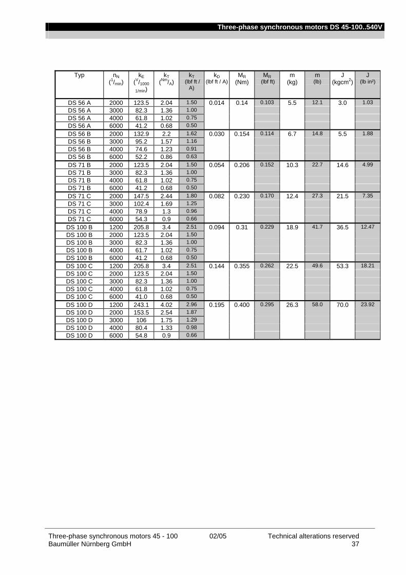
Three-phase synchronous motors DS 45-100..540V
Three-phase synchronous motors 45 - 100 02/05 Technical alterations reserved Baumüller Nürnberg GmbH 37
Typ nN (1/min)
kE (V/1000
1/min)
kT (Nm/A)
kT (lbf ft /
A)
kD (lbf ft / A)
MR (Nm)
MR (lbf ft)
m (kg)
m (lb)
J (kgcm2)
J (lb in²)
DS 56 A 2000 123.5 2.04 1.50 0.014 0.14 0.103 5.5 12.1 3.0 1.03 DS 56 A 3000 82.3 1.36 1.00 DS 56 A 4000 61.8 1.02 0.75 DS 56 A 6000 41.2 0.68 0.50 DS 56 B 2000 132.9 2.2 1.62 0.030 0.154 0.114 6.7 14.8 5.5 1.88 DS 56 B 3000 95.2 1.57 1.16 DS 56 B 4000 74.6 1.23 0.91 DS 56 B 6000 52.2 0.86 0.63 DS 71 B 2000 123.5 2.04 1.50 0.054 0.206 0.152 10.3 22.7 14.6 4.99 DS 71 B 3000 82.3 1.36 1.00 DS 71 B 4000 61.8 1.02 0.75 DS 71 B 6000 41.2 0.68 0.50 DS 71 C 2000 147.5 2.44 1.80 0.082 0.230 0.170 12.4 27.3 21.5 7.35 DS 71 C 3000 102.4 1.69 1.25 DS 71 C 4000 78.9 1.3 0.96 DS 71 C 6000 54.3 0.9 0.66 DS 100 B 1200 205.8 3.4 2.51 0.094 0.31 0.229 18.9 41.7 36.5 12.47 DS 100 B 2000 123.5 2.04 1.50 DS 100 B 3000 82.3 1.36 1.00 DS 100 B 4000 61.7 1.02 0.75 DS 100 B 6000 41.2 0.68 0.50 DS 100 C 1200 205.8 3.4 2.51 0.144 0.355 0.262 22.5 49.6 53.3 18.21 DS 100 C 2000 123.5 2.04 1.50 DS 100 C 3000 82.3 1.36 1.00 DS 100 C 4000 61.8 1.02 0.75 DS 100 C 6000 41.0 0.68 0.50 DS 100 D 1200 243.1 4.02 2.96 0.195 0.400 0.295 26.3 58.0 70.0 23.92 DS 100 D 2000 153.5 2.54 1.87 DS 100 D 3000 106 1.75 1.29 DS 100 D 4000 80.4 1.33 0.98 DS 100 D 6000 54.8 0.9 0.66

Three-phase synchronous motors DS 45-100..540V
Technical alterations reserved 02/05 Three-phase synchronous motors 45 - 100 38 Baumüller Nürnberg GmbH
Radial force diagrams
Permissible radial forces FR at the shaft end All bearings are dimensioned for a service life of approx. 20.000 operating hours; the loads specified in the following must not be exceeded. The specified permissible radial forces FR are valid only for horizontal mounting of the motor without additional axial forces. Axial load of the motor shaft When mounting clutches. pulleys. etc. onto the motor shaft. axial forces must not occur! Therefore use the internal thread of the shaft end as assembly aid. Example Force acting on the end of the shaft end (for force acting on the middle of the shaft end Fr x 1.1) Bearing life 20.000 h; shaft end with keyway
0
1000
2000
3000
4000
5000
6000
7000
8000
9000
10000
0 500 1000 1500 2000 2500 3000 3500 4000 4500
Fr [ N ]
n [ 1
/min
]
0
50
100
150
200
250
M [
Nm
]
Kugellager / Ball bearing Welle / Shaft
Welle
Kugellager
Explanation of the example The radial force Fr of the application is used to determine the possible maximum speed of the bearing in the “Ball bearing” characteristic.
Radial force 850 N => maximum speed 4250 min-1
The maximum transmittable torque results from the “Shaft” characteristic. Radial force 850 N => maximum transmittable torque 185 Nm

Three-phase synchronous motors DS 45-100..540V
Three-phase synchronous motors 45 - 100 02/05 Technical alterations reserved Baumüller Nürnberg GmbH 39
DS in standard version or with fan
DS 36
0
1500
3000
4500
6000
7500
9000
10500
0 50 100 150 200 250 300 350 400 450
Fr [ N ]
n [ 1
/min
]
0
1
2
3
4
5
6
7
M [
Nm
]
Kugellager / Ball bearing Welle / Shaft
DS 45
0
1000
2000
3000
4000
5000
6000
7000
8000
9000
0 100 200 300 400 500 600 700 800 900 1000
Fr [ N ]
n [ 1
/min
]
0
2
4
6
8
10
12
14
16
18
M [
Nm
]
Kugellager / Ball bearing Welle / Shaft
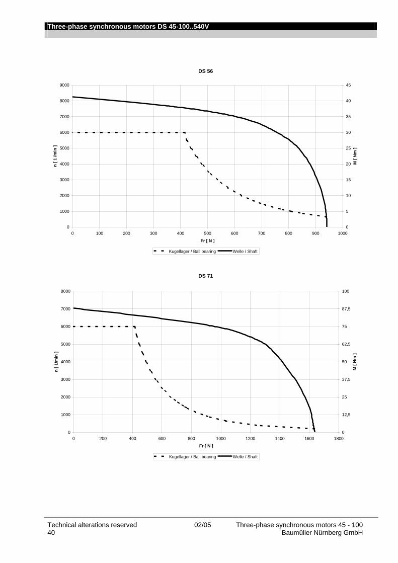
Three-phase synchronous motors DS 45-100..540V
Technical alterations reserved 02/05 Three-phase synchronous motors 45 - 100 40 Baumüller Nürnberg GmbH
DS 56
0
1000
2000
3000
4000
5000
6000
7000
8000
9000
0 100 200 300 400 500 600 700 800 900 1000
Fr [ N ]
n [ 1
/min
]
0
5
10
15
20
25
30
35
40
45
M [
Nm
]
Kugellager / Ball bearing Welle / Shaft
DS 71
0
1000
2000
3000
4000
5000
6000
7000
8000
0 200 400 600 800 1000 1200 1400 1600 1800
Fr [ N ]
n [ 1
/min
]
0
12,5
25
37,5
50
62,5
75
87,5
100
M [
Nm
]
Kugellager / Ball bearing Welle / Shaft
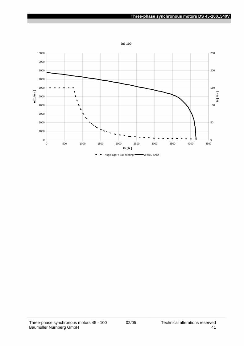
Three-phase synchronous motors DS 45-100..540V
Three-phase synchronous motors 45 - 100 02/05 Technical alterations reserved Baumüller Nürnberg GmbH 41
DS 100
0
1000
2000
3000
4000
5000
6000
7000
8000
9000
10000
0 500 1000 1500 2000 2500 3000 3500 4000 4500
Fr [ N ]
n [ 1
/min
]
0
50
100
150
200
250
M [
Nm
]
Kugellager / Ball bearing Welle / Shaft

Three-phase synchronous motors DS 45-100..540V
Technical alterations reserved 02/05 Three-phase synchronous motors 45 - 100 42 Baumüller Nürnberg GmbH
DS in short version
DS 56 (Kurz / Short)
0
1000
2000
3000
4000
5000
6000
7000
8000
9000
0 200 400 600 800 1000 1200 1400 1600 1800
Fr [ N ]
n [ 1
/min
]
0
5
10
15
20
25
30
35
40
45
M [
Nm
]
Kugellager / Ball bearing Welle / Shaft
DS 71 (Kurz / Short)
0
1000
2000
3000
4000
5000
6000
7000
8000
9000
0 200 400 600 800 1000 1200 1400 1600 1800 2000
Fr [ N ]
n [ 1
/min
]
0
5
10
15
20
25
30
35
40
45
M [
Nm
]
Kugellager / Ball bearing Welle / Shaft

Three-phase synchronous motors DS 45-100..540V
Three-phase synchronous motors 45 - 100 02/05 Technical alterations reserved Baumüller Nürnberg GmbH 43
DS 100 (Kurz / Short)
0
1000
2000
3000
4000
5000
6000
7000
8000
0 1000 2000 3000 4000 5000 6000
Fr [ N ]
n [ 1
/min
]
0
20
40
60
80
100
120
140
160
M [
Nm
]
Kugellager / Ball bearing Welle / Shaft

Three-phase synchronous motors DS 45-100..540V
Technical alterations reserved 02/05 Three-phase synchronous motors 45 - 100 44 Baumüller Nürnberg GmbH
Main connection – terminal marking and connector assignment Main connection via terminal box The thermal sensor for the resolver is connected via the encoder cable. Connection diagram
U V W ----------------Power connection SL ---------------------Protective earth B+ B- -----------------Brake (option)
Frame size 56 71 100 Stud M4 M6 M8
metric gland M20 and M16 M25 and M16 M16 and M40 Main connection via connector
The connector size is determined by the standstill current I0 of the motor used. The thermal sensor for the resolver is connected via the encoder cable. Poles of the female main connectors
Pin Signal Color / marking
Size 1
I < 15 A
A
B C
D
3
41
1
3 4 A B C D
Phase U PE
Phase V Phase W
B+ B-
U green / yellow
V V W W W
red black white yellow
Size 1.5
I < 50 A
- +
2 1
W
V
U
U V W
+ - 1 2
Phase U Phase V Phase W
PE B+ B-
U V V
W W W green / yellow
red black white yellow
View to contact side of female connector

Three-phase synchronous motors DS 45-100..540V
Three-phase synchronous motors 45 - 100 02/05 Technical alterations reserved Baumüller Nürnberg GmbH 45
Thermal sensor On resolver use. the temperature sensor is connected via the encoder plug. For SinCos encoder use. connection is effected via the main connection.
KTY84 - 130
0200400600800
100012001400160018002000
-50 0 50 100 150 200
Temperatur/Temperature (°C)
Wid
erst
and/
Res
ista
nce
(Ohm
)
The motor temperature is continuously monitored using the thermal sensor type KTY 84-130. The above shown resistance results when the sensor is supplied with a measuring current of 2 mA.
Fan data Fan for type DSO 56 4656 ZW - 956 230V. 50/60Hz; 0.12A 4606 ZW - 958 115V. 60 Hz Fan for type DSO/ 71 and DSO/LIO 100 148VK028172 230V. 50/60Hz; 0.2A 148VK028272 115V. 50/60Hz; 0.3A Type of protection
IP54
Connection 6-pin connector Fan connection
Pin Signal
1
2
Phase U
Neutral N
PE
View to contact side of female connector
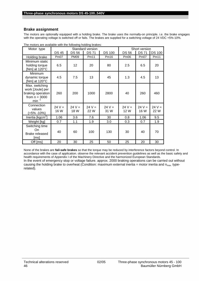
Three-phase synchronous motors DS 45-100..540V
Technical alterations reserved 02/05 Three-phase synchronous motors 45 - 100 46 Baumüller Nürnberg GmbH
Brake assignment The motors are optionally equipped with a holding brake. The brake uses the normally-on principle. i.e. the brake engages with the operating voltage is switched off or fails. The brakes are supplied for a switching voltage of 24 VDC +5%-10%. The motors are available with the following holding brakes:
Motor type Standard version Short version DS 45 DS 56 DS 71 DS 100 DS 56 DS 71 DS 100
Holding brake Pm07 PM09 Pm11 Pm16 Pm06 Pm07 Pm11 Minimum static holding torque [Nm] at 120°C
6.5 12 20 80 2.5 6.5 20
Minimum dynamic torque [Nm] at 120°C
4.5 7.5 13 45 1.3 4.5 13
Max. switching work [Joule] per
braking operation from n = 3000
min -1
260 200 1000 2800 40 260 460
Connection values
(+5% -10%)
24 V = 16 W
24 V = 18 W
24 V = 22 W
24 V = 31 W
24 V = 12 W
24 V = 16 W
24 V = 22 W
Inertia [kgcm2] 1.06 3.6 7.6 30 0.8 1.06 9.5 Weight [kg] 0.7 1.1 1.9 3.0 0.3 0.7 1.9
Switching time On
Brake released [ms]
40 60 100 130 30 40 70
Off [ms] 20 30 25 50 25 20 30 None of the brakes are fail-safe brakes so that the torque may be reduced by interference factors beyond control. In accordance with the case of application. observe the relevant accident prevention guidelines as well as the basic safety and health requirements of Appendix I of the Machinery Directive and the harmonized European Standards. In the event of emergency stop or voltage failure. approx. 2000 braking operations can be carried out without causing the holding brake to overheat (Condition: maximum external inertia = motor inertia and nmax. type-related).
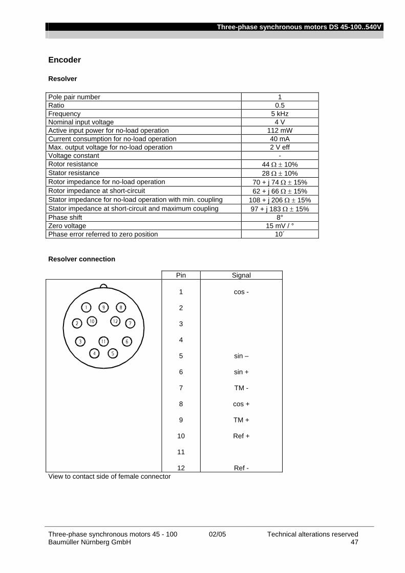
Three-phase synchronous motors DS 45-100..540V
Three-phase synchronous motors 45 - 100 02/05 Technical alterations reserved Baumüller Nürnberg GmbH 47
Encoder
Resolver Pole pair number 1 Ratio 0.5 Frequency 5 kHz Nominal input voltage 4 V Active input power for no-load operation 112 mW Current consumption for no-load operation 40 mA Max. output voltage for no-load operation 2 V eff Voltage constant - Rotor resistance 44 Ω ± 10% Stator resistance 28 Ω ± 10% Rotor impedance for no-load operation 70 + j 74 Ω ± 15% Rotor impedance at short-circuit 62 + j 66 Ω ± 15% Stator impedance for no-load operation with min. coupling 108 + j 206 Ω ± 15% Stator impedance at short-circuit and maximum coupling 97 + j 183 Ω ± 15% Phase shift 8° Zero voltage 15 mV / ° Phase error referred to zero position 10´
Resolver connection
Pin Signal
1
2
3
4
5
6
7
8
9
10
11
12
cos -
sin –
sin +
TM -
cos +
TM +
Ref +
Ref - View to contact side of female connector
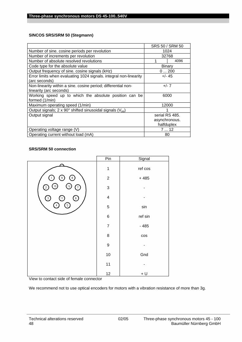
Three-phase synchronous motors DS 45-100..540V
Technical alterations reserved 02/05 Three-phase synchronous motors 45 - 100 48 Baumüller Nürnberg GmbH
SINCOS SRS/SRM 50 (Stegmann) SRS 50 / SRM 50 Number of sine. cosine periods per revolution 1024 Number of increments per revolution 32768 Number of absolute resolved revolutions 1 4096 Code type for the absolute value Binary Output frequency of sine. cosine signals (kHz) 0 ... 200 Error limits when evaluating 1024 signals. integral non-linearity (arc seconds)
+/- 45
Non-linearity within a sine. cosine period; differential non-linearity (arc seconds)
+/- 7
Working speed up to which the absolute position can be formed (1/min)
6000
Maximum operating speed (1/min) 12000 Output signals; 2 x 90° shifted sinusoidal signals (Vpp) 1 Output signal serial RS 485.
asynchronous. halfduplex
Operating voltage range (V) 7 ... 12 Operating current without load (mA) 80 SRS/SRM 50 connection
Pin Signal
1
2
3
4
5
6
7
8
9
10
11
12
ref cos
+ 485
-
-
sin
ref sin
- 485
cos
-
Gnd
-
+ U View to contact side of female connector We recommend not to use optical encoders for motors with a vibration resistance of more than 3g.
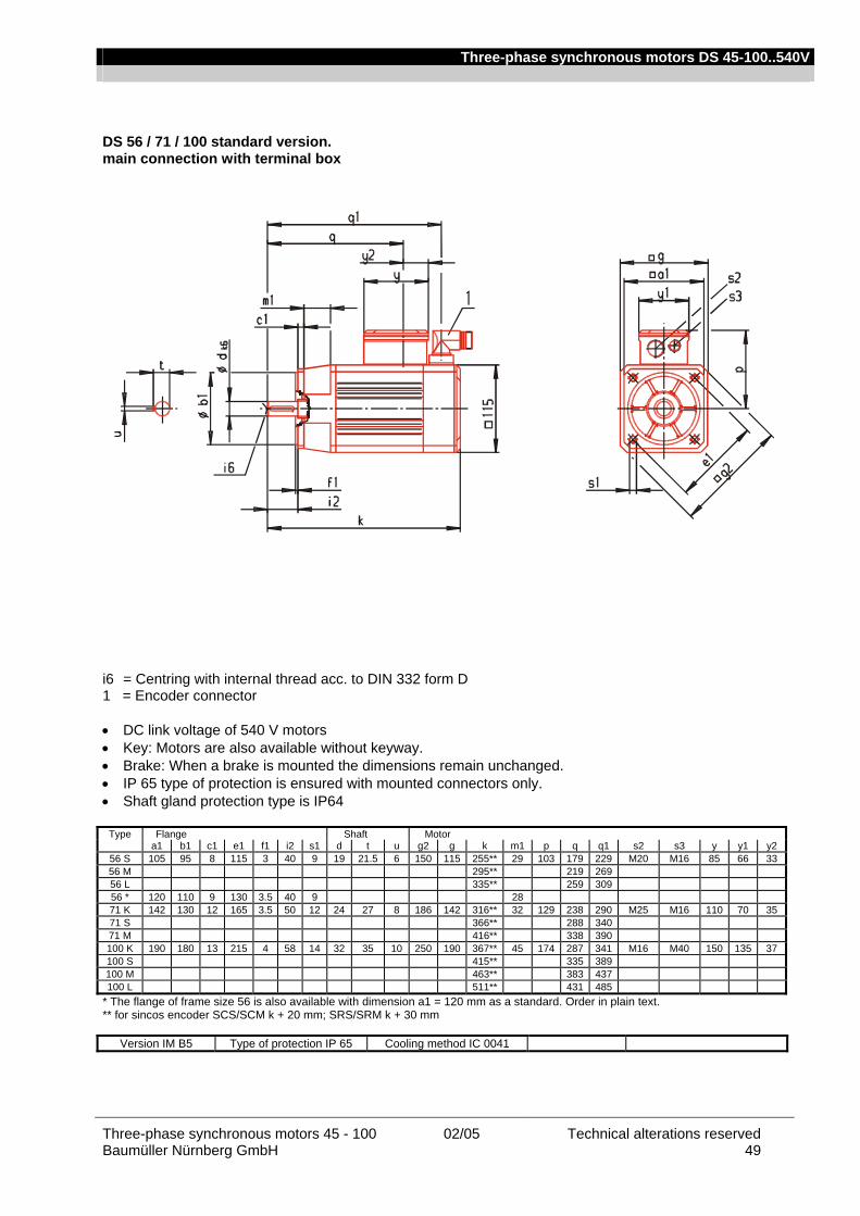
Three-phase synchronous motors DS 45-100..540V
Three-phase synchronous motors 45 - 100 02/05 Technical alterations reserved Baumüller Nürnberg GmbH 49
DS 56 / 71 / 100 standard version. main connection with terminal box i6 = Centring with internal thread acc. to DIN 332 form D 1 = Encoder connector • DC link voltage of 540 V motors • Key: Motors are also available without keyway. • Brake: When a brake is mounted the dimensions remain unchanged. • IP 65 type of protection is ensured with mounted connectors only. • Shaft gland protection type is IP64
Type Flange Shaft Motor a1 b1 c1 e1 f1 i2 s1 d t u g2 g k m1 p q q1 s2 s3 y y1 y2
56 S 105 95 8 115 3 40 9 19 21.5 6 150 115 255** 29 103 179 229 M20 M16 85 66 33 56 M 295** 219 269 56 L 335** 259 309 56 * 120 110 9 130 3.5 40 9 28 71 K 142 130 12 165 3.5 50 12 24 27 8 186 142 316** 32 129 238 290 M25 M16 110 70 35 71 S 366** 288 340 71 M 416** 338 390 100 K 190 180 13 215 4 58 14 32 35 10 250 190 367** 45 174 287 341 M16 M40 150 135 37 100 S 415** 335 389 100 M 463** 383 437 100 L 511** 431 485
* The flange of frame size 56 is also available with dimension a1 = 120 mm as a standard. Order in plain text. ** for sincos encoder SCS/SCM k + 20 mm; SRS/SRM k + 30 mm
Version IM B5 Type of protection IP 65 Cooling method IC 0041
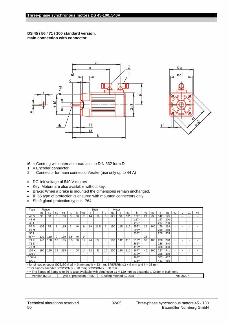
Three-phase synchronous motors DS 45-100..540V
Technical alterations reserved 02/05 Three-phase synchronous motors 45 - 100 50 Baumüller Nürnberg GmbH
DS 45 / 56 / 71 / 100 standard version. main connection with connector i6 = Centring with internal thread acc. to DIN 332 form D 1 = Encoder connector 2 = Connector for main connection/brake (use only up to 44 A) • DC link voltage of 540 V motors • Key: Motors are also available without key. • Brake: When a brake is mounted the dimensions remain unchanged. • IP 65 type of protection is ensured with mounted connectors only. • Shaft gland protection type is IP64
Type Flange Shaft Motor a1 b1 c1 e1 f1 i2 s1 d t u g2 g g3 k m1 p1 q q1 q2 y y1 y2
45 S 90 80 8 100 3 30 7 14 16 5 121 90 90* 192* 27 82 142 175 - - - - 45 M 217* 167 200 45 L 267* 217 250 56 S 105 95 8 115 3 40 9 19 21.5 6 150 115 115 255** 29 100 179 229 - - - - 56 M 295** 219 269 56 L 335** 259 309
56 *** 120 110 9 130 3.5 40 9 28 71 K 142 130 12 165 3.5 50 12 24 27 8 186 142 115 316** 32 100 238 290 - - - - 71 S 366** 288 340 71 M 416** 338 390 100 K 190 180 13 215 4 58 14 32 35 10 250 190 115 367** 45 100 287 341 - - - - 100 S 415** 335 389 100 M 463** 383 437 100 L 511** 431 485
* for sincos encoder SCS/SCM g3 + 9 mm and k + 33 mm; SRS/SRM g3 + 9 mm and k + 35 mm ** for sincos encoder SCS/SCM k + 20 mm; SRS/SRM k + 30 mm *** The flange of frame size 56 is also available with dimension a1 = 120 mm as a standard. Order in plain text.
Version IM B5 Type of protection IP 65 Cooling method IC 0041 70599207

Three-phase synchronous motors DS 45-100..540V
Three-phase synchronous motors 45 - 100 02/05 Technical alterations reserved Baumüller Nürnberg GmbH 51
DS 56 / 71 / 100 standard version with fan. main connection with terminal box i6 = Centring with internal thread acc. to DIN 332 form D 1 = Fan connector 2 = Encoder connector • DC link voltage of 540 V motors • Key: Motors are also available without key • Brake: When a brake is mounted the dimensions remain unchanged. • IP 54 type of protection is ensured with mounted connectors only. • Shaft gland protection type is IP64 Type Flange Shaft Motor
a1 b1 c1 e1 f1 i2 s1 d t u g2 g k m1 p q q1 q3 y y1 y2 s2 s3 56 S 105 95 8 115 3 40 9 19 21.5 6 167 132 411 29 103 179 229 78 85 66 33 M20 M16 56 M 451 219 269 56 L 491 259 309 56 * 120 110 9 130 3.5 40 9 28 71 K 142 130 12 165 3.5 50 12 24 27 8 218 180 503 32 129 238 290 90 110 70 35 M25 M16 71 S 553 288 340 71 M 603 338 390 100 K 190 180 13 215 4 58 14 32 35 10 270 210 576 45 174 287 341 115 150 135 37 M16 M40 100 S 624 335 389 100 M 672 383 437 100 L 720 431 485 * The flange of frame size 56 is also available with dimension a1 = 120 mm as a standard. Order in plain text.
Version IM B5 Type of protection IP 54 Cooling method IC 0641 70599208

Three-phase synchronous motors DS 45-100..540V
Technical alterations reserved 02/05 Three-phase synchronous motors 45 - 100 52 Baumüller Nürnberg GmbH
DS 56 / 71 / 100 standard version with fan. main connection with connector i6 = Centring with internal thread acc. to DIN 332 form D 1 = Fan connector 2 = Encoder connector 3 = Connector for main connection/brake • DC link voltage of 540 V motors • Key: Motors are also available without key • Brake: When a brake is mounted the dimensions remain unchanged. • IP 54 type of protection is ensured with mounted connectors only. • Shaft gland protection type is IP64 Type Flange Shaft Motor
a1 b1 c1 e1 f1 i2 s1 d t u g2 g k m1 p1 q q1 q3 y y1 y2 s2 s3 56 S 105 95 8 115 3 40 9 19 21.5 6 167 132 411 29 97 179 229 78 56 M 451 219 269 56 L 491 259 309 56 * 120 110 9 130 3.5 40 9 28 71 K 142 130 12 165 3.5 50 12 24 27 8 218 180 503 32 110 238 290 90 71 S 553 288 340 71 M 603 338 390 100 K 190 180 13 215 4 58 14 32 35 10 270 210 576 45 134 287 341 115 100 S 624 335 389 100 M 672 383 437 100 L 720 431 485 * The flange of frame size 56 is also available with dimension a1 = 120 mm as a standard. Order in plain text.
Bauform IM B5 Schutzart IP 54 Kühlart IC 0641 70599209
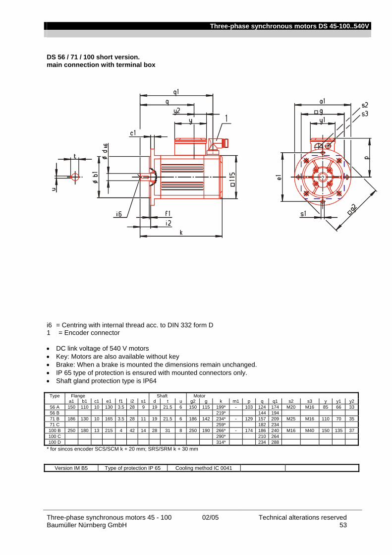
Three-phase synchronous motors DS 45-100..540V
Three-phase synchronous motors 45 - 100 02/05 Technical alterations reserved Baumüller Nürnberg GmbH 53
DS 56 / 71 / 100 short version. main connection with terminal box i6 = Centring with internal thread acc. to DIN 332 form D 1 = Encoder connector • DC link voltage of 540 V motors • Key: Motors are also available without key • Brake: When a brake is mounted the dimensions remain unchanged. • IP 65 type of protection is ensured with mounted connectors only. • Shaft gland protection type is IP64
Type Flange Shaft Motor a1 b1 c1 e1 f1 i2 s1 d t u g2 g k m1 p q q1 s2 s3 y y1 y2
56 A 150 110 10 130 3.5 28 9 19 21.5 6 150 115 199* - 103 124 174 M20 M16 85 66 33 56 B 219* 144 194 71 B 186 130 10 165 3.5 28 11 19 21.5 6 186 142 234* - 129 157 209 M25 M16 110 70 35 71 C 259* 182 234 100 B 250 180 13 215 4 42 14 28 31 8 250 190 266* - 174 186 240 M16 M40 150 135 37 100 C 290* 210 264 100 D 314* 234 288
* for sincos encoder SCS/SCM k + 20 mm; SRS/SRM k + 30 mm
Version IM B5 Type of protection IP 65 Cooling method IC 0041
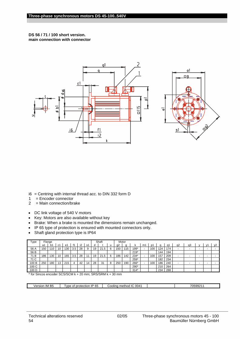
Three-phase synchronous motors DS 45-100..540V
Technical alterations reserved 02/05 Three-phase synchronous motors 45 - 100 54 Baumüller Nürnberg GmbH
DS 56 / 71 / 100 short version. main connection with connector i6 = Centring with internal thread acc. to DIN 332 form D 1 = Encoder connector 2 = Main connection/brake • DC link voltage of 540 V motors • Key: Motors are also available without key • Brake: When a brake is mounted the dimensions remain unchanged. • IP 65 type of protection is ensured with mounted connectors only. • Shaft gland protection type is IP64
Type Flange Shaft Motor a1 b1 c1 e1 f1 i2 s1 d t u g2 g k m1 p1 q q1 q2 q3 y y1 y2
56 A 150 110 10 130 3.5 28 9 19 21.5 6 150 115 199* - 100 124 174 - - - - - 56 B 219* 144 194 71 B 186 130 10 165 3.5 28 11 19 21.5 6 186 142 234* - 100 157 209 - - - - - 71 C 259* 182 234 100 B 250 180 13 215 4 42 14 28 31 8 250 190 266* - 100 186 240 - - - - - 100 C 290* 210 264 100 D 314* 234 288
* for Sincos encoder SCS/SCM k + 20 mm; SRS/SRM k + 30 mm
Version IM B5 Type of protection IP 65 Cooling method IC 0041 70599211
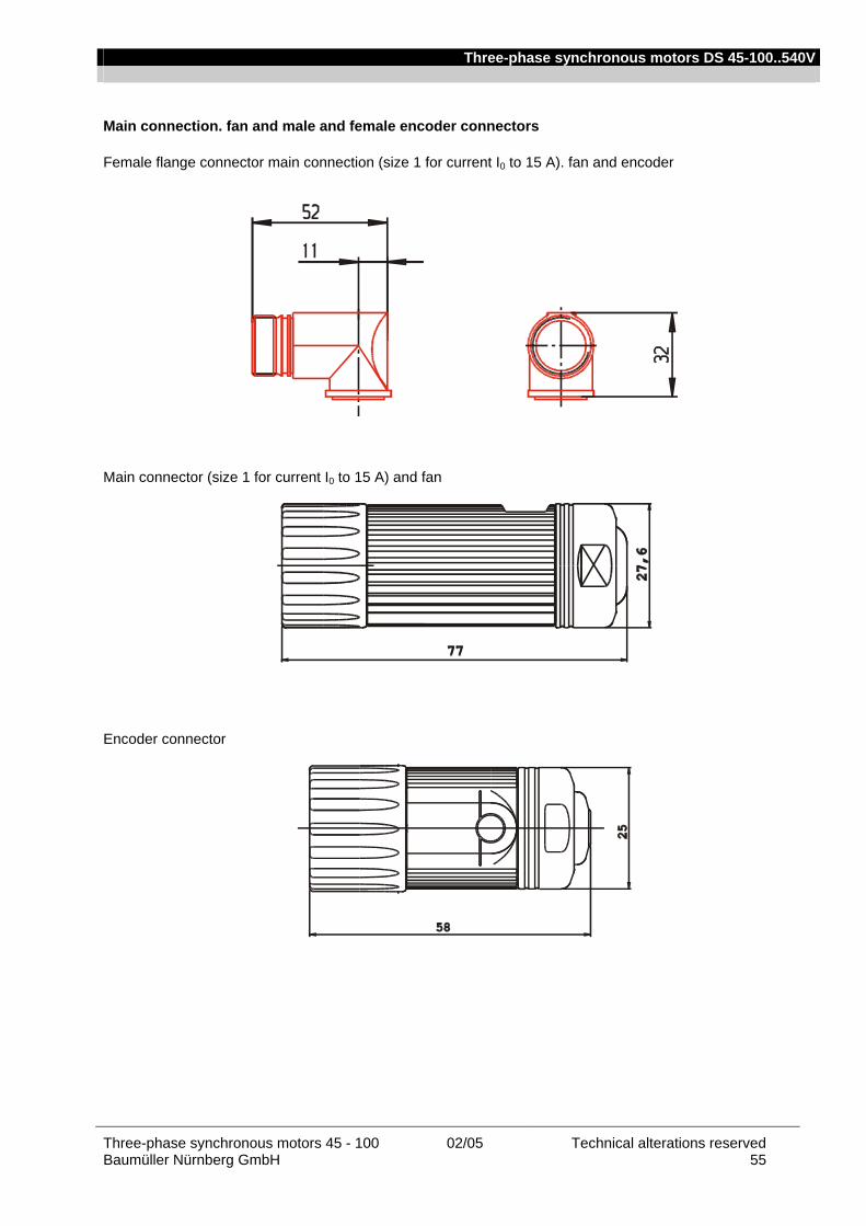
Three-phase synchronous motors DS 45-100..540V
Three-phase synchronous motors 45 - 100 02/05 Technical alterations reserved Baumüller Nürnberg GmbH 55
Main connection. fan and male and female encoder connectors Female flange connector main connection (size 1 for current I0 to 15 A). fan and encoder
Main connector (size 1 for current I0 to 15 A) and fan
Encoder connector
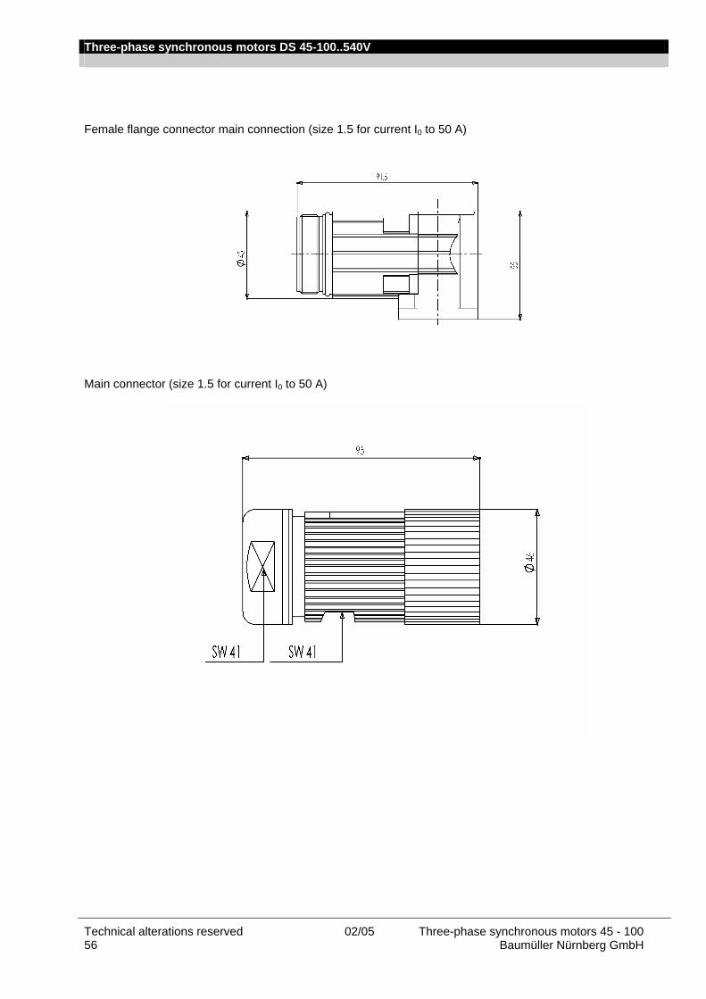
Three-phase synchronous motors DS 45-100..540V
Technical alterations reserved 02/05 Three-phase synchronous motors 45 - 100 56 Baumüller Nürnberg GmbH
Female flange connector main connection (size 1.5 for current I0 to 50 A)
Main connector (size 1.5 for current I0 to 50 A)
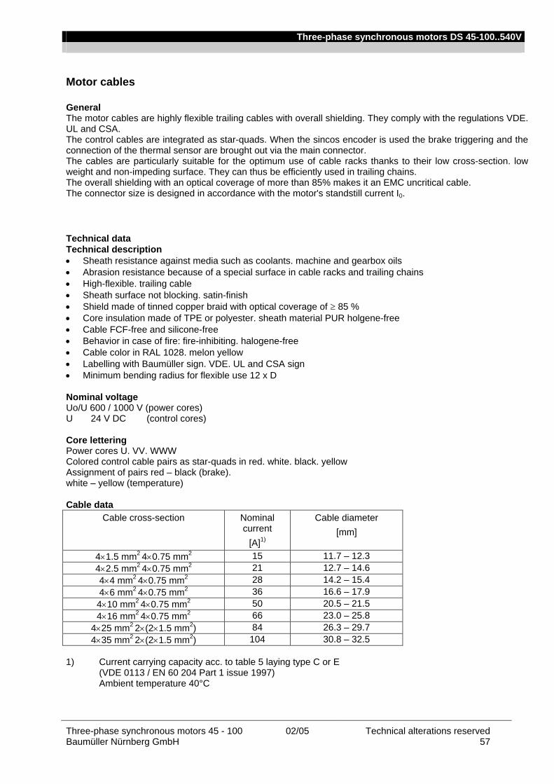
Three-phase synchronous motors DS 45-100..540V
Three-phase synchronous motors 45 - 100 02/05 Technical alterations reserved Baumüller Nürnberg GmbH 57
Motor cables General The motor cables are highly flexible trailing cables with overall shielding. They comply with the regulations VDE. UL and CSA. The control cables are integrated as star-quads. When the sincos encoder is used the brake triggering and the connection of the thermal sensor are brought out via the main connector. The cables are particularly suitable for the optimum use of cable racks thanks to their low cross-section. low weight and non-impeding surface. They can thus be efficiently used in trailing chains. The overall shielding with an optical coverage of more than 85% makes it an EMC uncritical cable. The connector size is designed in accordance with the motor's standstill current I0. Technical data Technical description • Sheath resistance against media such as coolants. machine and gearbox oils • Abrasion resistance because of a special surface in cable racks and trailing chains • High-flexible. trailing cable • Sheath surface not blocking. satin-finish • Shield made of tinned copper braid with optical coverage of ≥ 85 % • Core insulation made of TPE or polyester. sheath material PUR holgene-free • Cable FCF-free and silicone-free • Behavior in case of fire: fire-inhibiting. halogene-free • Cable color in RAL 1028. melon yellow • Labelling with Baumüller sign. VDE. UL and CSA sign • Minimum bending radius for flexible use 12 x D Nominal voltage Uo/U 600 / 1000 V (power cores) U 24 V DC (control cores) Core lettering Power cores U. VV. WWW Colored control cable pairs as star-quads in red. white. black. yellow Assignment of pairs red – black (brake). white – yellow (temperature) Cable data
Cable cross-section Nominal current
[A]1)
Cable diameter [mm]
4×1.5 mm2 4×0.75 mm2 15 11.7 – 12.3 4×2.5 mm2 4×0.75 mm2 21 12.7 – 14.6 4×4 mm2 4×0.75 mm2 28 14.2 – 15.4 4×6 mm2 4×0.75 mm2 36 16.6 – 17.9 4×10 mm2 4×0.75 mm2 50 20.5 – 21.5 4×16 mm2 4×0.75 mm2 66 23.0 – 25.8
4×25 mm2 2×(2×1.5 mm2) 84 26.3 – 29.7 4×35 mm2 2×(2×1.5 mm2) 104 30.8 – 32.5
1) Current carrying capacity acc. to table 5 laying type C or E
(VDE 0113 / EN 60 204 Part 1 issue 1997) Ambient temperature 40°C
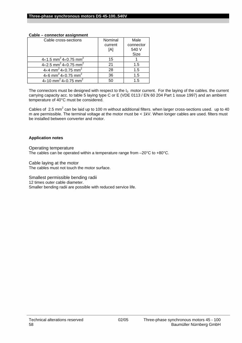
Three-phase synchronous motors DS 45-100..540V
Technical alterations reserved 02/05 Three-phase synchronous motors 45 - 100 58 Baumüller Nürnberg GmbH
Cable – connector assignment
Cable cross-sections Nominal current
[A]
Male connector
540 V Size
4×1.5 mm2 4×0.75 mm2 15 1 4×2.5 mm2 4×0.75 mm2 21 1.5 4×4 mm2 4×0.75 mm2 28 1.5 4×6 mm2 4×0.75 mm2 36 1.5 4×10 mm2 4×0.75 mm2 50 1.5
The connectors must be designed with respect to the I0 motor current. For the laying of the cables. the current carrying capacity acc. to table 5 laying type C or E (VDE 0113 / EN 60 204 Part 1 issue 1997) and an ambient temperature of 40°C must be considered. Cables of 2.5 mm2 can be laid up to 100 m without additional filters. when larger cross-sections used. up to 40 m are permissible. The terminal voltage at the motor must be < 1kV. When longer cables are used. filters must be installed between converter and motor. Application notes Operating temperature The cables can be operated within a temperature range from –20°C to +80°C. Cable laying at the motor The cables must not touch the motor surface. Smallest permissible bending radii 12 times outer cable diameter. Smaller bending radii are possible with reduced service life.

Three-phase synchronous motors DS 45-100..540V
Three-phase synchronous motors 45 - 100 02/05 Technical alterations reserved Baumüller Nürnberg GmbH 59
Main connection cables / Assembled cable with connector Nominal current: 15 A Nominal current: 36 A Cable 4 x 1.5 mm² + 4x 0.75 mm² Cable 4 x 6 mm² + 4x 0.75 mm² with connector Size1 with connector Size1.5 Length in m Article no. Length in m Article no.
5 324781 5 326600 7 324782 7 326601 10 324783 10 326602 15 324784 15 326603 20 324785 20 326604 25 324786 25 326605 30 324787 30 326606 35 324788 35 326607 40 324789 40 326608 50 324790 75 324791
100 324792 Nominal current: 21 A Nominal current: 50 A Cable 4 x 2.5 mm² + 4x 0.75 mm² Cable 4 x 10 mm² + 4x 0.75 mm² with connector Size1.5 with connector Size1.5 Length in m Article no. Length in m Article no.
5 326577 5 326609 7 326578 7 326610 10 326579 10 326611 15 326580 15 326612 20 326581 20 326613 25 326582 25 326614 30 326583 30 326615 35 326584 35 326616 40 326585 40 326617 50 326586 75 326587
100 326588 Connector Nominal current: 28 A Type Article no. Cable 4 x 4 mm² + 4x 0.75 mm² Size 1 f. 4x1.5mm2 261740 with connector Size1.5 Size 1.5 f. 4x2.5mm2 o. 4mm2 326574 Length in m Article no. Size 1.5 f. 4x6mm2 o.10mm2 326569
5 326589 7 326591 10 326592 15 326593 20 326594 25 326596 30 326597 35 326598 40 326599
Larger cable cross-sections on request. Longer cables can also be used. The terminal voltage at the motor must be < 1kV. In this case. however. filters must be installed between converter and motor.
Three-phase synchronous motors DS 45-100..540V
Technical alterations reserved 02/05 Three-phase synchronous motors 45 - 100 60 Baumüller Nürnberg GmbH
Encoder cables General A fully preassembled encoder cable is used for all encoder systems. Motor connection is via a 12-pin round signal connector and converter connection via a 15-pin sub-D plug. The encoder cables are available as 'trailing' and 'non-trailing' cables. The trailing cable is suitable for use in trailing chains. for example. As opposed to the 'non-trailing' cable. the cable sheath consists of tougher PUR for use in environments with acids and bases (coolants) instead of PVC. Up to a length of 10 m. the cables are available in 1 m sections (1 m. 2 m. 10 m). From a cable length of 10 m. the sections come in 5 m intervals (10 m. 15 m. …).
In the case of servo motors. the resolver encoder system links the temperature sensor with the converter via the encoder cable.
Technical data 1. Technical description – non-trailing
• LiYCY. 5x (2x0.14mm²) + 2 x 0.5mm² copper lead. twisted pair
• PVC sheath. grey
• 1st end: 12-pin signal circular connector with 12 female contacts
• 2nd end: 15-pin D-Sub connector with male contacts and locking screws 4-4OUNC
• Baumüller labelling. black
• Outer diameter 9.0 mm (+/-3mm)
• Bending radius: r ≥ 60 mm (fixed installation). r ≥ 135 mm (flexible use)
• Nominal voltage: 250VAC 2. Technical description – trailing
• Li12YC11Y. 5x (2x0.14mm²) + 2 x 0.5mm² copper lead. twisted pair
• PU sheath. black
• 1st end: 12-pin signal circular connector with 12 female contacts
• 2nd end: 15-pin D-Sub connector with male contacts and locking screws 4-4OUNC
• Baumüller labelling. white
• Outer diameter 9.0 mm (+/-3mm)
• Bending radius: r ≥ 70 mm (fixed installation). r ≥ 100 mm (flexible use)
• Nominal voltage: 300VAC

Three-phase synchronous motors DS 45-100..540V
Three-phase synchronous motors 45 - 100 02/05 Technical alterations reserved Baumüller Nürnberg GmbH 61
Application notes • Operating temperature trailing non-trailing Limit temperature at the surface at the surface
no / few movements -40 °C to +80 °C - 30 °C to +80 °C
continuous movements - 30 °C to +80 °C -5 °C to + 70 °C • Cable laying at the motor The cables must not touch the motor surface. Ordering data Encoder cables / preassembled cables with connector Encoder cable non-trailing. assembled Cable 5 x (2x014mm2) + 2 x 0.5 mm² with connector
trailing. assembled Cable 5 x (2x014mm2) + 2 x 0.5 mm² with connector
Length in m Article no. Length in m Article no. 1 243601 3 246658 2 211338 4 243379 3 219333 5 239540 4 231166 6 242954 5 209879 8 239541 6 220197 10 239542 7 216455 15 239543 8 220429 20 239544 10 210052 25 239545 15 215716 30 239546 20 218568 35 239547 25 218569 40 240520 30 217094 45 240521 35 216444 50 240522 40 217095 55 244033 45 217567 60 245484 50 217568 55 217569
60 217570 Encoder connector
Article no.
70 232088 Encoder connector
201833
Commissioning and maintenance instructions Please contact us for our commissioning and maintenance instructions for motor commissioning.

Three-phase synchronous motors DS 45-100..540V
Technical alterations reserved 02/05 Three-phase synchronous motors 45 - 100 62 Baumüller Nürnberg GmbH
Three-phase synchronous motors DS 45-100..540V
Three-phase synchronous motors 45 - 100 02/05 Technical alterations reserved Baumüller Nürnberg GmbH 63
Three-phase synchronous motors DS 45-100..540V
Technical alterations reserved 02/05 Three-phase synchronous motors 45 - 100 64 Baumüller Nürnberg GmbH
Headquater: Baumüller Nürnberg GmbH • Ostendstraße 80-90 • D-90482 Nürnberg Tel +49 (0)911 5432 -0 • Fax +49 (0)911 5432 -130 • http://www.baumueller.com
Information subject to change
Drive Center National
Darmstadt Baumüller Nürnberg GmbH Waldstraße 1 • D-64347 Griesheim Tel +49- (0)6155 8430-00 • Fax +49- (0)6155 8430-20 Düsseldorf Baumüller Nürnberg GmbH Jacob-Kaiser-Str. 7 • D-47877 Willich-Münchheide Tel +49- (0)2154-487-0 • Fax +49- (0)2154-487-59 Dresden Baumüller Kamenz GmbH Nordstraße 57 • D-01917 Kamenz Tel +49- (0)3578 3406-0 • Fax +49- (0)3578 3406-50 Hannover Baumüller Nürnberg GmbH Bohlenweg 10 • D-30853 Langenhagen Tel +49-(0)511 771968-0 • Fax +49- 0)511 771968-77 Nürnberg Baumüller Nürnberg GmbH Ostendstr. 80-90 • D-90482 Nürnberg Tel +49- (0)911-5432-501 • Fax +49- (0)911-5432-510 Stuttgart Baumüller Nürnberg GmbH Hahnweidstr. 21• D-73230 Kirchheim / Teck Tel +49- (0)7021-48557-10 • Fax +49-(0)7021-48557-77
Drive Center International
Australia / Sydney Office Baumueller Australia Pty. Ltd. 19 Baker Street • Botany NSW 2019 • SYDNEY, Tel +61 2 83350-100 • F +61 2 83350-169 Austria Baumüller Austria Ges.mbH Im Bäckerfeld 17 • A-4060 Leonding Tel +43 (0)732 674414-0 • Fax +43 (0)732 674414-32 England Baumüller (UK) Ltd. 14 Redlands Centre • GB-Coulsdon, Surrey CR5 2HT Tel +44(0)208 76329-90 • Fax +44(0)208 76329-59 France Baumüller France S.à.r.l. Zone de la Malnoue 39, Avenue de l´Europe • F- 77184 Emerainville Tel +33 1 6461-6622 • Fax +33 1 6461-6006 India Baumüller KAT India Pvt. Ltd. Dattaprasad Apartment • Flat No. 7, 3Rd Floor, B/7, 1206, APTE Road • IND- 411 004 Pune Tel +91 20 25513311 • Fax +91 20 25513388 Italy Baumüller Italia s.r.l., Viale Italia, 12 • I-20094 Corsico (Mi), Tel +39 02 45100-181 • Fax +39 02 45100-426 Spain Baumüller Ibérica S.A. Ausias Marc, 13 1º 2ª • E- 08010 Barcelona Tel +34 (0)93 34 26 926 • Fax +34 (0)93 27 01 321 Switzerland Baumüller Suisse S.A. Rue des Usines 22 • CH-2000 Neuchâtel Tel +41 (0)32 7301-260 • Fax +41 (0)32 7301-351
The Netherlands Baumüller Benelux B.V. Platinastraat 141 • NL-2718 SR Zoetermeer Tel +31(0)79-3614-290 • Fax +31(0)79-3614-339 Turkey BAUMÜLLER MOTOR KONTROL SISTEM SAN. VE TIC. LTD. STI Colak Ismail Sok., No:31/1 • TR-81070 Istanbul-Suadiye Tel +90 (0)216 372-2485 • Fax +90 (0)216 372-7570 USA Baumueller Hartford Inc. 117 West Dudley Town Road • USA-Bloomfield, CT 06002 Tel +1 860 -243 0232 • Fax +1 860 -286 3080 USA Baumueller Chicago Corp. 405 Algonquin Rd. • USA-Mount Prospect, Ill 60056 Tel +1 847 956-7392 • Fax +1 847 956-7925
Representatives International
Brasil NC SERVICE INDÚSTRIA E COMÉRCIO LTDA. Av. Juruá, 150, - Barueri - SP • BR- 06455 - 010 Tel +55 (0)11 4195-0502 • Fax +55 (0)11 4195-2479 China Beijing Yanghai Automation Technology Co., Ltd. Room 1008, No.7, Huaqing Business Building, Iluaqing Garden, Wudaokou, Haidian District, Beijing 100083, P.R.C. Tel +86 (0)10 82867980 • Fax +86 (0)10 82867987 China Sunary Automatic Technology Limited Company 3 rd Floor No.476 Chunxiao Rd. Zhangjiang High-Tech Park Pudong, Shanghai 201203 Tel +86 (0)21 50809898 • Fax +86 (0)21 53087675 Denmark Robotek EL & Teknik A/S Blokken 31 Postbox 30 • DK-3460 Birkerød Tel +45 4484 7360 • Fax +45 4484 4177 Iran PAK GOSTAR Co. 502, 5th Floor, BORJ-E SEFID, PASDARAN Ave TEHRAN - IRAN Tel +98 21 2553868-70 • Fax + +98 21 2547703 Korea BOMAC SYSTEMS 712 Yucheon Factophia • 196 Anyang-7 dong, Mananku, Anyangsi, • Kyungkido 430-017, Korea Tel +82 31 467-2030 • Fax +82 31 467-2033 Poland Mekelburger Polska Ul. Kościelna 39 F/3 • PL-60537 Poznań Tel. / Fax +48 (0)61-8481520 Russia Permanent K&M Wolokolamskoye Chaussee 73 • Office 517 Moscow ,125424 Tel +7 (0)95 9563867 • Fax +7 (0)95 7803429 USA Industrial Drives Design, Inc. 668 Flinn Avenue Unit 28 • USA- Moorpark CA 93021 Tel +1 805 378-1170 • Fax +1 805 378-1171 Venezuela,Columbia,Equador Nimbus International C.A. C.C. Parque Tuy, Local P-18 YV-Ocumare del Tuy 1209 Tel +58(0)239-2251347 • Fax +58(0)239-2257149
Manufacturing locations
Motors Baumüller Nürnberg GmbH Ostendstraße 80- 90 • D-90482 Nürnberg Tel +49- (0)911-5432-0 • Fax +49- (0)911-5432-130 Baumüller Nürnberg GmbH Werk Kitzingen Floßhafenstraße 2 • D-97318 Kitzingen Tel +49- (0)9321-70080 • Fax +49- (0)9321-700888 Baumüller Brno s.r.o Skalice nad Svitavou 72 CZ- 67901 Skalice nad Svitavou, Tel +420 516-499 111 • Fax +420 516-499 117 Baumüller Kamenz GmbH Nordstraße 57 • D-01917 Kamenz Tel +49- (0)3578 3406-0 • Fax +49- (0)3578 3406-50 Small Motors Baumüller Nürnberg GmbH Werk Bad Gandersheim Flugplatzweg 2 • D-37581 Bad Gandersheim Tel +49- (0)5382 9805-0 • Fax 49- (0)5382 9805-55 Electronics Baumüller Nürnberg GmbH Ostendstraße 80- 90 • D-90482 Nürnberg Tel +49- (0)911-5432-293 • Fax +49- (0)911-5432-328 Baumüller Dravinja d.o.o. Delavska cesta 10 • SI-3210 Slovenske- Konjice Tel +386 3-75723-00 • Fax +386 3-75723-32/33
Systems
Baumüller Anlagen-Systemtechnik GmbH & Co. KG Ostendstraße 84 • D-90482 Nürnberg Tel +49- (0)911-54408-0 • Fax +49- (0)911-54408-749
Services
Baumüller Reparaturwerk GmbH & Co KG Andernacher Straße 19 • D-90411 Nürnberg Tel +49- (0)911-9552-0 • Fax+49- (0)911-9552-999 München Baumüller München GmbH Meglingerstraße 58 • D-81477 München Tel +49- (0)89 748898-10 • Fax +49- (0)89 748898-75
2.179.e.02/05.05B
02/05
e
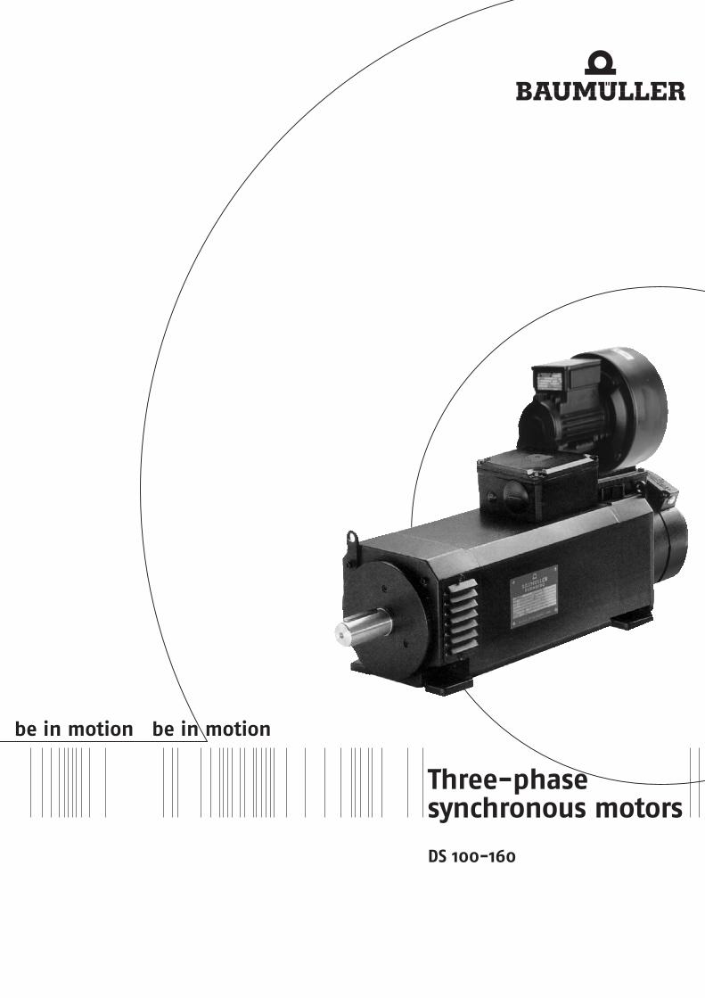


Three-phase synchronous motors 100 - 160
Technical alterations reserved Three-phase synchronous motors DS 100 – 160 03/03 1 Baumüller Nürnberg GmbH
Table of contents Three-phase synchronous motors DS ...................................................................................................... 2 General technical data ................................................................................................................................ 2 Ratings definition ........................................................................................................................................ 3 Winding isolation and temperature rise......................................................................................................... 3 Explanation of the motor data ...................................................................................................................... 3 Type key .................................................................................................................................................... 4 Technical data............................................................................................................................................ 5
DS 100..23 R.. (IP 23 internally ventilated) .......................................................................................... 5 DS 132..23 R.. (IP 23 internally ventilated) .......................................................................................... 6 DS 160..23R.. (IP 23 internally ventilated) ........................................................................................... 7 DS 100..54R.. IP 54 surface-ventilated ............................................................................................... 8 DS 132..54R.. IP 54 surface-ventilated ............................................................................................... 9 DS 100..54U.. (IP 54 unventilated) ....................................................................................................10 DS 132..54U.. (IP 54 unventilated) ....................................................................................................11
Bearings and shaft load..............................................................................................................................12 Radial force diagrams ................................................................................................................................13 Main connection – Terminal marking ...........................................................................................................16 Thermal sensor .........................................................................................................................................16 Noise intensity...........................................................................................................................................17 Vibration severity .......................................................................................................................................17 Fan data ...................................................................................................................................................17 Brake assignment ......................................................................................................................................18 Encoder ....................................................................................................................................................19
Resolver..........................................................................................................................................19 SINCOS SRS/SRM 50 (Stegmann) ...................................................................................................20 ECN 1313 EQN 1325 (Heidenhain) ..................................................................................................21
Dimension drawings ...................................................................................................................................22 DS 100 / 132 / 160 IP 23 internally ventilated .................................................................................22 DS 100 / 132 IP 54 surface-cooled .................................................................................................23 DS 100 / 132 IP 54 self-cooled .......................................................................................................24 Flange dimensions of frame size 100 / 132 / 160................................................................................25 Filters frame size 100 / 1332 / 160.....................................................................................................26 Encoder male and female connectors ................................................................................................27
Motor cables..............................................................................................................................................28 Nominal voltage ...............................................................................................................................28 Core lettering ...................................................................................................................................28 Cable data.......................................................................................................................................28
Commissioning and maintenance instructions..............................................................................................32

Three-phase synchronous motors 100 - 160
Technical alterations reserved 2 03/03 Three-phase synchronous motors DS 100 – 160 Baumüller Nürnberg GmbH
Three-phase synchronous motors DS
Three-phase synchronous motors of the DS series are permanently excited motors. Boasting a very high power density, very high efficiency and high response the motors are perfectly suitable for most sophisticated applications in mechanical engineering. This is additionally supported by a high overload capability. These durable, compact motors are also largely maintenance-free, which is an extra benefit to ensure most efficient operation.
General technical data Version IM B3, IM B34, IM B35 Type of protection IP23 Internally cooled, with fan IP54 surface-cooled with fan or uncooled
Forced ventilation / standard N-end, top, left or right hand side Air conduction non-drive end to drive end, lateral air outlet at drive end
Forced ventilation / option Drive end, top, left or right hand side Air conduction drive end to non-drive end, lateral air outlet at N-end
Connection Main connection U V W Terminal box Control connection 12-pin connector Brake Terminal box of brake Thermal sensor in the main connection Cooling IP 23 IC 06 Internally cooled machine (air conduction from N- to D-end) IP 54 IC 0641 Surface-cooled machine (air conduction from N- to D-end) IP 54 IC 0041 completely enclosed machine Thermal sensor Linear thermal sensor for evaluation in the controller Temperature rise ∆ϑ ≤ 105K Insulation class F acc. to EN 60034-1 Temperature range 0....+ 40°C, Storage -30°C...+85°C Paint black matt RAL 9005 Bearing D-end: standard = ball bearing; option = roller bearing, locating bearing on the N-end
Terminal box D- and N-end; top , left or right hand side Balance quality N According to DIN ISO 2373 R, S On request Vibrationproof / standard radial 3 g / axial 1g , 10 .. 55 Hz acc. to EN 60068-2-6 Higher vibration resistance on request Flange acc. to IEC standard Dimension b1: up to flange size a1 300 mm tolerance j6 as from flange size a1 300 mm tolerance h6 shaft end cylindrical Acc. to DIN 748 with shaft key DIN 6885; also available without keyway) centering with internal thread acc. to DIN 332 form D Dimension d: ≤∅ 50 mm tolerance k6; d: >∅ 50 mm tolerance m6 Brake Disk brakes from Baumüller, N-end mounting as a module
other brands on request Actual speed encoder 2-pin resolver Option: Sincos Encoder Other encoders on request UL Option in preparation

Three-phase synchronous motors 100 - 160
Technical alterations reserved Three-phase synchronous motors DS 100 – 160 03/03 3 Baumüller Nürnberg GmbH
Ratings definition The ratings (torques) listed in the table apply to continuous operation (S1) with nominal speed at a maximum ambient temperature of 40°C with the machine being installed below 1000m a.m.s.l.
If motors are to be operated in an ambient temperature of more than 40 °C or altitudes above 1000 m a.m.s.l., the required list nominal power PL (list torque Mn) results from the product of the factors k1, k2 specified in the table and the required power P (torque M).
Ambient temperature
40 °C 45°C 50 °C 55°C 60°C
Correction factor k1
1 1.06 1.13 1.22 1.34
Altitude a.m.s.l. up to
1.000m
2.000m
3.000m
4.000m
5.000m
Correction factor k2
1 1.07 1.16 1.27 1.55
For ambient temperatures above 40 °C and enclosed installation of motors, it is absolutely necessary to contact the manufacturer, because design changes may be necessary. If, with increasing site altitude above 1000 m, the ambient temperature decreases by approx. 10 °C per 1000 m increase in altitude, no power correction is necessary.
Winding isolation and temperature rise All machines of this series are designed in insulation class F according to EN 60034 for a permissible winding temperature of 105 K at a room temperature of up to 40 °C. The insulation is resistant against gases and vapours of combustible materials and it meets the requirements placed on a moisture-proof and tropical insulation.
A special insulation that can be obtained for an extra charge is necessary if concentrated acid vapours and metallic powders occur, with a permanent relative air humidity of more than 80% and as protection against termite and mould fungus attacks.
In the case of converters with a DC link voltage > 500 V, the cables between the converter and the motor must not be longer than 20 meters. For longer cables, additional measures (e.g. motor filters) must be provided. The maximum permissible terminal voltage is 1000 V.
Explanation of the motor data PN Nominal power ( kW ) with nominal speed nN in continuous operation (S1) MN Nominal torque ( kW ) with nominal speed nN in continuous operation (S1) Nominal r.m.s. current ( A ) IdN Magnetizing current for field weakening ( A ) UN Nominal voltage ( V ) KE / COLD referred to 1000 min-1 motor e.m.f. (voltage constant) (V) cos ϕ power factor ηN Efficiency fN Nominal frequency ( Hz ) J Rotor inertia incl. resolver without holding brake (kg m²) m Weight ( kg ) Mo,max Maximum standstill torque (Nm) Ratings of synchronous motors DS The specified ratings are achieved in converter operation (field-oriented control) with a clock frequency of 4 kHz in the power stage. Overload capacity According to technical data sheet
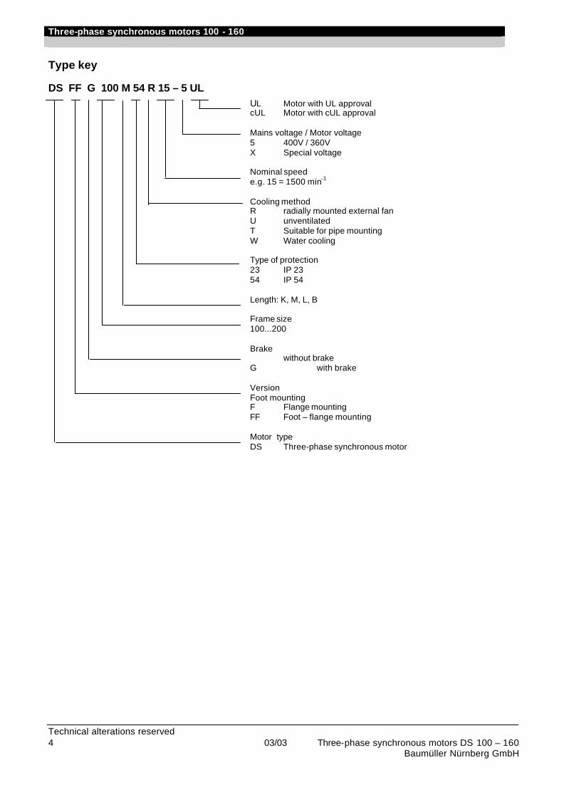
Three-phase synchronous motors 100 - 160
Technical alterations reserved 4 03/03 Three-phase synchronous motors DS 100 – 160 Baumüller Nürnberg GmbH
Type key
DS FF G 100 M 54 R 15 – 5 UL UL Motor with UL approval cUL Motor with cUL approval Mains voltage / Motor voltage 5 400V / 360V X Special voltage Nominal speed e.g. 15 = 1500 min-1 Cooling method R radially mounted external fan U unventilated T Suitable for pipe mounting W Water cooling Type of protection 23 IP 23 54 IP 54 Length: K, M, L, B Frame size 100...200 Brake without brake G with brake Version Foot mounting F Flange mounting FF Foot – flange mounting Motor type DS Three-phase synchronous motor
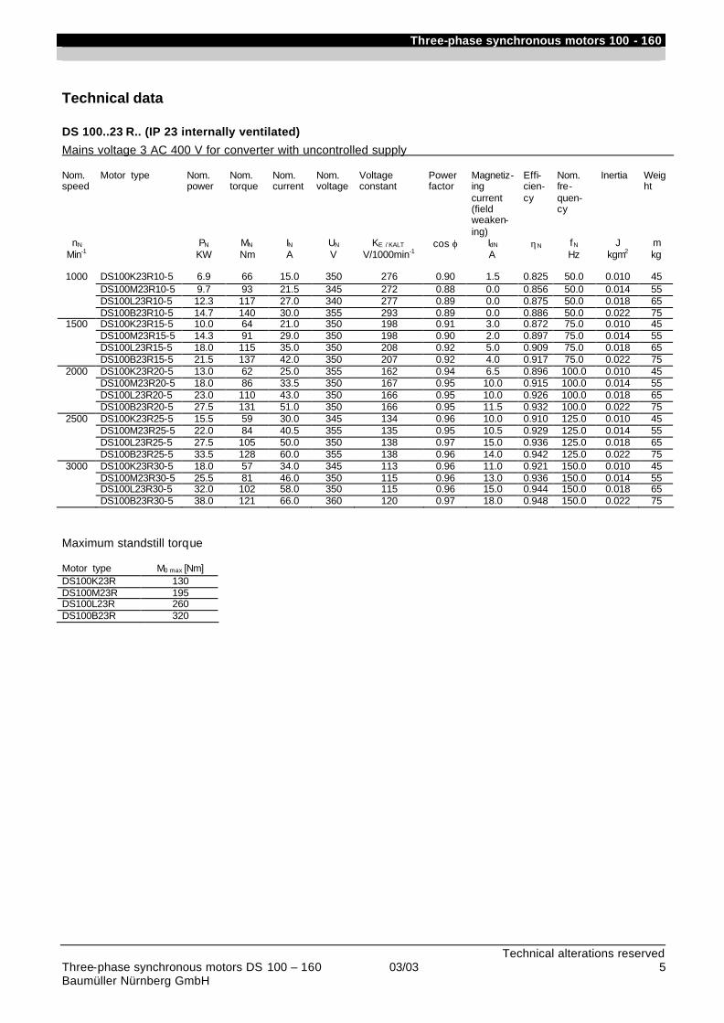
Three-phase synchronous motors 100 - 160
Technical alterations reserved Three-phase synchronous motors DS 100 – 160 03/03 5 Baumüller Nürnberg GmbH
Technical data
DS 100..23 R.. (IP 23 internally ventilated)
Mains voltage 3 AC 400 V for converter with uncontrolled supply Nom. speed
Motor type Nom. power
Nom. torque
Nom. current
Nom. voltage
Voltage constant
Power factor
Magnetiz-ing current (field weaken-ing)
Effi-cien-cy
Nom. fre-quen-cy
Inertia Weight
nN PN MN IN UN KE / KALT cos ϕ IdN ηN fN J m Min-1 KW Nm A V V/1000min-1 A Hz kgm2 kg
1000 DS100K23R10-5 6.9 66 15.0 350 276 0.90 1.5 0.825 50.0 0.010 45
DS100M23R10-5 9.7 93 21.5 345 272 0.88 0.0 0.856 50.0 0.014 55 DS100L23R10-5 12.3 117 27.0 340 277 0.89 0.0 0.875 50.0 0.018 65 DS100B23R10-5 14.7 140 30.0 355 293 0.89 0.0 0.886 50.0 0.022 75
1500 DS100K23R15-5 10.0 64 21.0 350 198 0.91 3.0 0.872 75.0 0.010 45 DS100M23R15-5 14.3 91 29.0 350 198 0.90 2.0 0.897 75.0 0.014 55 DS100L23R15-5 18.0 115 35.0 350 208 0.92 5.0 0.909 75.0 0.018 65 DS100B23R15-5 21.5 137 42.0 350 207 0.92 4.0 0.917 75.0 0.022 75
2000 DS100K23R20-5 13.0 62 25.0 355 162 0.94 6.5 0.896 100.0 0.010 45 DS100M23R20-5 18.0 86 33.5 350 167 0.95 10.0 0.915 100.0 0.014 55 DS100L23R20-5 23.0 110 43.0 350 166 0.95 10.0 0.926 100.0 0.018 65 DS100B23R20-5 27.5 131 51.0 350 166 0.95 11.5 0.932 100.0 0.022 75
2500 DS100K23R25-5 15.5 59 30.0 345 134 0.96 10.0 0.910 125.0 0.010 45 DS100M23R25-5 22.0 84 40.5 355 135 0.95 10.5 0.929 125.0 0.014 55 DS100L23R25-5 27.5 105 50.0 350 138 0.97 15.0 0.936 125.0 0.018 65 DS100B23R25-5 33.5 128 60.0 355 138 0.96 14.0 0.942 125.0 0.022 75
3000 DS100K23R30-5 18.0 57 34.0 345 113 0.96 11.0 0.921 150.0 0.010 45 DS100M23R30-5 25.5 81 46.0 350 115 0.96 13.0 0.936 150.0 0.014 55 DS100L23R30-5 32.0 102 58.0 350 115 0.96 15.0 0.944 150.0 0.018 65 DS100B23R30-5 38.0 121 66.0 360 120 0.97 18.0 0.948 150.0 0.022 75
Maximum standstill torque Motor type M0 max [Nm] DS100K23R 130 DS100M23R 195 DS100L23R 260 DS100B23R 320
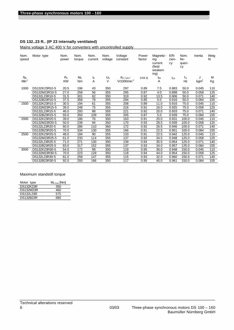
Three-phase synchronous motors 100 - 160
Technical alterations reserved 6 03/03 Three-phase synchronous motors DS 100 – 160 Baumüller Nürnberg GmbH
DS 132..23 R.. (IP 23 internally ventilated) Mains voltage 3 AC 400 V for converters with uncontrolled supply Nom. speed
Motor type Nom. power
Nom. torque
Nom. current
Nom. voltage
Voltage constant
Power factor
Magnetiz-ing current (field weaken-ing)
Effi-cien-cy
Nom. fre-quen-cy
Inertia Weight
NN PN MN IN UN KE / KALT cos ϕ IdN ηN fN J M Min-1 KW Nm A V V/1000min-1 A Hz kgm2 Kg
1000 DS132K23R10-5 20.5 196 43 350 297 0.89 7.5 0.883 50.0 0.045 110
DS132M23R10-5 27.0 258 56 355 295 0.87 4.0 0.898 50.0 0.058 125 DS132L23R10-5 31.5 301 62 350 319 0.92 13.5 0.906 50.0 0.071 140 DS132B23R10-5 37.5 358 78 355 294 0.85 0.0 0.916 50.0 0.084 155
1500 DS132K23R15-5 30.5 194 61 355 208 0.89 11.0 0.916 75.0 0.045 110 DS132M23R15-5 39.0 248 75 355 216 0.91 16.0 0.925 75.0 0.058 125 DS132L23R15-5 46.0 293 88 355 221 0.92 20.0 0.933 75.0 0.071 140 DS132B23R15-5 55.0 350 109 355 205 0.87 5.0 0.939 75.0 0.084 155
2000 DS132K23R20-5 39.0 186 76 350 163 0.91 20.0 0.931 100.0 0.045 110 DS132M23R20-5 50.0 239 94 350 170 0.93 28.5 0.939 100.0 0.058 125 DS132L23R20-5 60.0 286 110 360 172 0.92 26.5 0.946 100.0 0.071 140 DS132B23R20-5 70.0 334 130 355 166 0.91 22.5 0.951 100.0 0.084 155
2500 DS132K23R25-5 48.0 184 90 355 133 0.91 22.5 0.942 125.0 0.045 110 DS132M23R25-5 61.0 233 114 355 137 0.92 34.5 0.948 125.0 0.058 125 DS132L23R25-5 71.0 271 130 350 139 0.94 35.5 0.954 125.0 0.071 140 DS132B23R25-5 83.0 317 152 355 137 0.93 34.0 0.957 125.0 0.084 155
3000 DS132K23R30-5 54.0 172 99 350 119 0.95 36.0 0.948 150.0 0.045 110 DS132M23R30-5 70.0 223 129 350 118 0.94 44.0 0.954 150.0 0.058 125 DS132L23R30-5 81.0 258 147 355 115 0.93 32.0 0.960 150.0 0.071 140 DS132B23R30-5 92.0 293 166 350 117 0.95 45.0 0.961 150.0 0.084 155
Maximum standstill torque Motor type M0 max [Nm] DS132K23R 350 DS132M23R 460 DS132L23R 575 DS132B23R 680
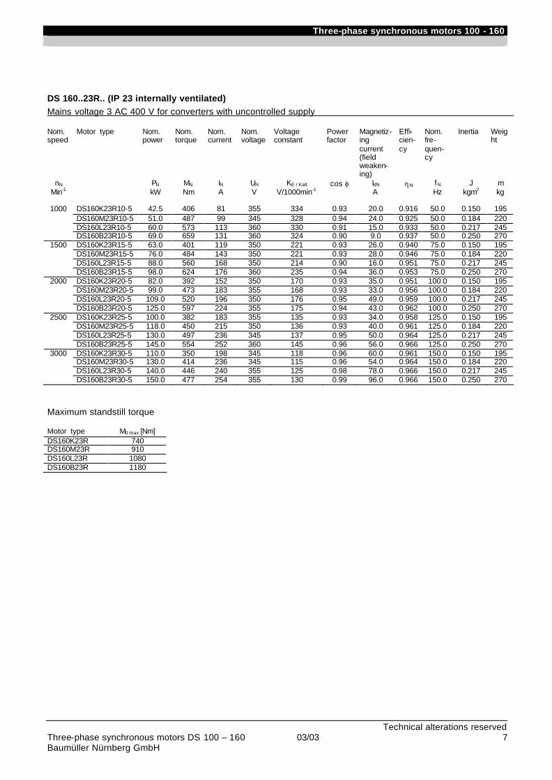
Three-phase synchronous motors 100 - 160
Technical alterations reserved Three-phase synchronous motors DS 100 – 160 03/03 7 Baumüller Nürnberg GmbH
DS 160..23R.. (IP 23 internally ventilated) Mains voltage 3 AC 400 V for converters with uncontrolled supply Nom. speed
Motor type Nom. power
Nom. torque
Nom. current
Nom. voltage
Voltage constant
Power factor
Magnetiz-ing current (field weaken-ing)
Effi-cien-cy
Nom. fre-quen-cy
Inertia Weight
nN PN MN IN UN KE / Kalt cos ϕ IdN ηN fN J m Min-1 kW Nm A V V/1000min-1 A Hz kgm2 kg
1000 DS160K23R10-5 42.5 406 81 355 334 0.93 20.0 0.916 50.0 0.150 195
DS160M23R10-5 51.0 487 99 345 328 0.94 24.0 0.925 50.0 0.184 220 DS160L23R10-5 60.0 573 113 360 330 0.91 15.0 0.933 50.0 0.217 245 DS160B23R10-5 69.0 659 131 360 324 0.90 9.0 0.937 50.0 0.250 270
1500 DS160K23R15-5 63.0 401 119 350 221 0.93 26.0 0.940 75.0 0.150 195 DS160M23R15-5 76.0 484 143 350 221 0.93 28.0 0.946 75.0 0.184 220 DS160L23R15-5 88.0 560 168 350 214 0.90 16.0 0.951 75.0 0.217 245 DS160B23R15-5 98.0 624 176 360 235 0.94 36.0 0.953 75.0 0.250 270
2000 DS160K23R20-5 82.0 392 152 350 170 0.93 35.0 0.951 100.0 0.150 195 DS160M23R20-5 99.0 473 183 355 168 0.93 33.0 0.956 100.0 0.184 220 DS160L23R20-5 109.0 520 196 350 176 0.95 49.0 0.959 100.0 0.217 245 DS160B23R20-5 125.0 597 224 355 175 0.94 43.0 0.962 100.0 0.250 270
2500 DS160K23R25-5 100.0 382 183 355 135 0.93 34.0 0.958 125.0 0.150 195 DS160M23R25-5 118.0 450 215 350 136 0.93 40.0 0.961 125.0 0.184 220 DS160L23R25-5 130.0 497 236 345 137 0.95 50.0 0.964 125.0 0.217 245 DS160B23R25-5 145.0 554 252 360 145 0.96 56.0 0.966 125.0 0.250 270
3000 DS160K23R30-5 110.0 350 198 345 118 0.96 60.0 0.961 150.0 0.150 195 DS160M23R30-5 130.0 414 236 345 115 0.96 54.0 0.964 150.0 0.184 220 DS160L23R30-5 140.0 446 240 355 125 0.98 78.0 0.966 150.0 0.217 245 DS160B23R30-5 150.0 477 254 355 130 0.99 96.0 0.966 150.0 0.250 270
Maximum standstill torque Motor type M0 max [Nm] DS160K23R 740 DS160M23R 910 DS160L23R 1080 DS160B23R 1180

Three-phase synchronous motors 100 - 160
Technical alterations reserved 8 03/03 Three-phase synchronous motors DS 100 – 160 Baumüller Nürnberg GmbH
DS 100..54R.. IP 54 surface-ventilated
Mains voltage 3 AC 400 V for converters with uncontrolled supply Nom. speed
Motor type Nom. power
Nom. torque
Nom. current
Nom. voltage
Voltage constant
Power factor
Magnetiz-ing current (field weaken-ing)
Effi-cien-cy
Nom. fre-quen-cy
Inertia Weight
nN PN MN IN UN KE / KALT cos ϕ IdN ηN fN J M Min-1 KW Nm A V V/1000min-1 A Hz kgm2 Kg
1100 DS100K54R11-5 5.0 43.0 10.2 350 276 0.92 0.0 0.873 55.0 0.010 45
DS100M54R11-5 7.5 65.0 15.5 335 271 0.91 0.0 0.890 55.0 0.014 55 DS100L54R11-5 10.0 87.0 20.5 340 277 0.91 0.0 0.900 55.0 0.018 65 DS100B54R11-5 12.0 104.0 23.5 355 293 0.91 0.0 0.907 55.0 0.022 75
1600 DS100K54R16-5 7.1 42.0 14.0 350 198 0.92 0.0 0.903 80.0 0.010 45 DS100M54R16-5 10.7 64.0 21.0 350 198 0.91 0.0 0.916 80.0 0.014 55 DS100L54R16-5 14.2 85.0 27.0 355 208 0.93 2.0 0.924 80.0 0.018 65 DS100B54R16-5 17.2 103.0 33.0 355 207 0.91 0.0 0.929 80.0 0.022 75
2000 DS100K54R20-5 8.7 41.5 17.0 355 162 0.92 0.0 0.916 100.0 0.010 45 DS100M54R20-5 13.1 62.5 25.0 360 167 0.91 0.0 0.928 100.0 0.014 55 DS100L54R20-5 17.4 83.0 33.0 360 166 0.91 0.0 0.935 100.0 0.018 65 DS100B54R20-5 21.0 100.0 38.5 350 172 0.95 4.0 0.938 100.0 0.022 75
2500 DS100K54R25-5 10.6 40.5 20.0 360 134 0.92 0.0 0.926 125.0 0.010 45 DS100M54R25-5 15.8 60.5 29.5 350 135 0.94 3.0 0.936 125.0 0.014 55 DS100L54R25-5 21.0 80.0 38.0 355 138 0.94 3.5 0.942 125.0 0.018 65 DS100B54R25-5 25.0 95.0 46.0 340 138 0.96 7.0 0.945 125.0 0.022 75
3000 DS100K54R30-5 12.3 39.0 23.0 360 113 0.92 0.0 0.932 150.0 0.010 45 DS100M54R30-5 18.0 57.0 33.0 350 115 0.95 3.0 0.941 150.0 0.014 55 DS100L54R30-5 24.0 76.5 44.0 355 115 0.94 3.0 0.947 150.0 0.018 65 DS100B54R30-5 28.0 89.0 50.0 350 120 0.98 10.0 0.949 150.0 0.022 75
Maximum standstill torque Motor type M0 max [Nm] DS100K54R 120 DS100M54R 175 DS100L54R 235 DS100B54R 290

Three-phase synchronous motors 100 - 160
Technical alterations reserved Three-phase synchronous motors DS 100 – 160 03/03 9 Baumüller Nürnberg GmbH
DS 132..54R.. IP 54 surface-ventilated Mains voltage 3 AC 400 V for converters with uncontrolled supply Nom. speed
Motor type Nom. power
Nom. torque
Nom. current
Nom. voltage
Voltage constant
Power factor
Magnetiz-ing current (field weaken-ing)
Effi-cien-cy
Nom. fre-quen-cy
Inertia Weight
NN PN MN IN UN KE / KALT cos ϕ IdN ηN fN J M Min-1 KW Nm A V V/1000min-1 A Hz kgm2 Kg
1100 DS132K54R11-5 13.5 117 26.0 360 297 0.90 0.0 0.922 55.0 0.045 110
DS132M54R11-5 18.0 156 35.0 350 295 0.90 0.0 0.930 55.0 0.058 125 DS132L54R11-5 22.0 191 40.0 360 319 0.94 5.0 0.935 55.0 0.071 140 DS132B54R11-5 26.0 225 51.0 345 293 0.91 0.0 0.939 55.0 0.084 155
1600 DS132K54R16-5 19.2 115 36.5 360 208 0.91 0.0 0.940 80.0 0.045 110 DS132M54R16-5 25.0 149 46.0 355 216 0.94 5.0 0.946 80.0 0.058 125 DS132L54R16-5 30.0 179 54.0 350 221 0.95 8.0 0.950 80.0 0.071 140 DS132B54R16-5 35.5 212 69.0 345 205 0.91 0.0 0.952 80.0 0.084 155
2000 DS132K54R20-5 23.0 110 44.5 350 163 0.91 0.0 0.947 100.0 0.045 110 DS132M54R20-5 30.0 143 56.0 360 170 0.91 0.0 0.952 100.0 0.058 125 DS132L54R20-5 36.0 172 67.0 355 172 0.91 0.0 0.956 100.0 0.071 140 DS132B54R20-5 42.5 203 82.0 345 166 0.92 0.0 0.957 100.0 0.084 155
2500 DS132K54R25-5 27.5 105 52.0 350 133 0.91 0.0 0.952 130.0 0.045 110 DS132M54R25-5 35.5 136 66.0 360 137 0.91 0.0 0.956 130.0 0.058 125 DS132L54R25-5 42.0 160 77.0 355 139 0.92 0.0 0.959 130.0 0.071 140 DS132B54R25-5 50.0 190 93.0 350 137 0.92 0.0 0.960 130.0 0.084 155
3000 DS132K54R30-5 31.0 99 55.0 360 119 0.95 5.0 0.954 150.0 0.045 110 DS132M54R30-5 40.0 127 72.0 345 118 0.96 10.0 0.958 150.0 0.058 125 DS132L54R30-5 47.0 150 88.0 350 114 0.93 0.0 0.959 150.0 0.071 140 DS132B54R30-5 55.0 175 99.0 355 117 0.93 0.0 0.960 150.0 0.084 155
Maximum standstill torque Motor type M0 max [Nm] DS132K54R 305 DS132M54R 400 DS132L54R 500 DS132B54R 600
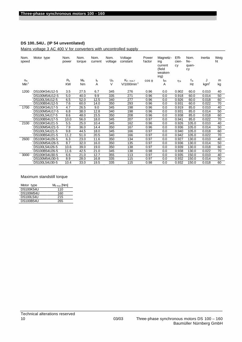
Three-phase synchronous motors 100 - 160
Technical alterations reserved 10 03/03 Three-phase synchronous motors DS 100 – 160 Baumüller Nürnberg GmbH
DS 100..54U.. (IP 54 unventilated) Mains voltage 3 AC 400 V for converters with uncontrolled supply Nom. speed
Motor type Nom. power
Nom. torque
Nom. current
Nom. voltage
Voltage constant
Power factor
Magnetiz-ing current (field weaken-ing)
Effi-cien-cy
Nom. fre-quen-cy
Inertia Weight
nN PN MN IN UN KE / KALT cos ϕ IdN ηN fN J m Min-1 KW Nm A V V/1000min-1 A Hz kgm2 kg
1200 DS100K54U12-5 3.5 27.5 6.7 345 276 0.96 0.0 0.902 60.0 0.010 40
DS100M54U12-5 5.0 40.0 9.9 335 271 0.96 0.0 0.918 60.0 0.014 50 DS100L54U12-5 6.5 52.0 12.5 340 277 0.96 0.0 0.926 60.0 0.018 60 DS100B54U12-5 7.6 60.0 14.0 350 293 0.96 0.0 0.931 60.0 0.022 70
1700 DS100K54U17-5 4.7 26.5 9.0 345 198 0.96 0.0 0.919 85.0 0.010 40 DS100M54U17-5 6.8 38.0 12.8 340 198 0.96 0.0 0.931 85.0 0.014 50 DS100L54U17-5 8.6 48.0 15.5 350 208 0.96 0.0 0.938 85.0 0.018 60 DS100B54U17-5 10.0 56.0 18.0 345 207 0.97 0.0 0.941 85.0 0.022 70
2100 DS100K54U21-5 5.5 25.0 10.4 345 162 0.96 0.0 0.926 105.0 0.010 40 DS100M54U21-5 7.9 36.0 14.4 350 167 0.96 0.0 0.936 105.0 0.014 50 DS100L54U21-5 9.8 44.5 18.0 345 166 0.97 0.0 0.940 105.0 0.018 60 DS100B54U21-5 11.2 51.0 20.5 340 166 0.97 0.0 0.942 105.0 0.022 70
2600 DS100K54U26-5 6.3 23.0 11.6 350 134 0.97 0.0 0.927 130.0 0.010 40 DS100M54U26-5 8.7 32.0 16.0 350 135 0.97 0.0 0.936 130.0 0.014 50 DS100L54U26-5 10.6 39.0 19.0 350 138 0.97 0.0 0.939 130.0 0.018 60 DS100B54U26-5 11.6 42.5 21.0 345 138 0.98 0.0 0.938 130.0 0.022 70
3000 DS100K54U30-5 6.6 21.0 12.7 355 113 0.97 0.0 0.935 150.0 0.010 40 DS100M54U30-5 8.9 28.0 16.8 335 115 0.97 0.0 0.932 150.0 0.014 50 DS100L54U30-5 10.4 33.0 19.5 335 115 0.98 0.0 0.932 150.0 0.018 60
Maximum standstill torque Motor type M0 max [Nm] DS100K54U 110 DS100M54U 160 DS100L54U 215 DS100B54U 265
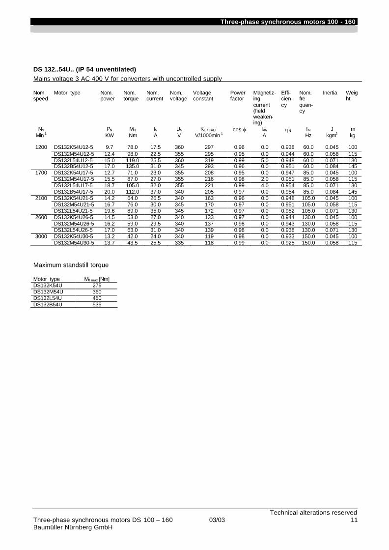
Three-phase synchronous motors 100 - 160
Technical alterations reserved Three-phase synchronous motors DS 100 – 160 03/03 11 Baumüller Nürnberg GmbH
DS 132..54U.. (IP 54 unventilated) Mains voltage 3 AC 400 V for converters with uncontrolled supply Nom. speed
Motor type Nom. power
Nom. torque
Nom. current
Nom. voltage
Voltage constant
Power factor
Magnetiz-ing current (field weaken-ing)
Effi-cien-cy
Nom. fre-quen-cy
Inertia Weight
NN PN MN IN UN KE / KALT cos ϕ IdN ηN fN J m Min-1 KW Nm A V V/1000min-1 A Hz kgm2 kg
1200 DS132K54U12-5 9.7 78.0 17.5 360 297 0.96 0.0 0.938 60.0 0.045 100
DS132M54U12-5 12.4 98.0 22.5 355 295 0.95 0.0 0.944 60.0 0.058 115 DS132L54U12-5 15.0 119.0 25.5 360 319 0.99 5.0 0.948 60.0 0.071 130 DS132B54U12-5 17.0 135.0 31.0 345 293 0.96 0.0 0.951 60.0 0.084 145
1700 DS132K54U17-5 12.7 71.0 23.0 355 208 0.95 0.0 0.947 85.0 0.045 100 DS132M54U17-5 15.5 87.0 27.0 355 216 0.98 2.0 0.951 85.0 0.058 115 DS132L54U17-5 18.7 105.0 32.0 355 221 0.99 4.0 0.954 85.0 0.071 130 DS132B54U17-5 20.0 112.0 37.0 340 205 0.97 0.0 0.954 85.0 0.084 145
2100 DS132K54U21-5 14.2 64.0 26.5 340 163 0.96 0.0 0.948 105.0 0.045 100 DS132M54U21-5 16.7 76.0 30.0 345 170 0.97 0.0 0.951 105.0 0.058 115 DS132L54U21-5 19.6 89.0 35.0 345 172 0.97 0.0 0.952 105.0 0.071 130
2600 DS132K54U26-5 14.5 53.0 27.0 340 133 0.97 0.0 0.944 130.0 0.045 100 DS132M54U26-5 16.2 59.0 29.5 340 137 0.98 0.0 0.943 130.0 0.058 115 DS132L54U26-5 17.0 63.0 31.0 340 139 0.98 0.0 0.938 130.0 0.071 130
3000 DS132K54U30-5 13.2 42.0 24.0 340 119 0.98 0.0 0.933 150.0 0.045 100 DS132M54U30-5 13.7 43.5 25.5 335 118 0.99 0.0 0.925 150.0 0.058 115
Maximum standstill torque Motor type M0 max [Nm] DS132K54U 275 DS132M54U 360 DS132L54U 450 DS132B54U 535
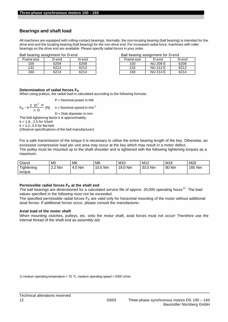
Three-phase synchronous motors 100 - 160
Technical alterations reserved 12 03/03 Three-phase synchronous motors DS 100 – 160 Baumüller Nürnberg GmbH
Bearings and shaft load All machines are equipped with rolling-contact bearings. Normally, the non-locating bearing (ball bearing) is intended for the drive end and the locating bearing (ball bearing) for the non-drive end. For increased radial force, machines with roller bearings on the drive end are available. Please specify radial forces in your order.
Ball bearing assignment for D-end Frame size D-end N-end
100 6209 6209 132 6212 6212 160 6214 6214
Ball bearing assignment for D-end Frame size D-end N-end
100 NU 209 E 6209 132 NU 212 E 6212 160 NU 214 E 6214
Determination of radial forces FR When using pulleys, the radial load is calculated according to the following formula:
P = Nominal power in kW
F k2 10 P
n DR
7=
⋅ ⋅⋅
[N] n = Nominal speed in min-1
D = Disk diameter in mm The belt tightening factor k is approximately: k = 1.8...2.5 for V-belt k = 2.2..3.5 for flat belt (Observe specifications of the belt manufacturer)
For a safe transmission of the torque it is necessary to utilise the entire bearing length of the key. Otherwise, an excessive compressive load per unit area may occur at the key which may result in a motor defect. The pulley must be mounted up to the shaft shoulder and is tightened with the following tightening torques as a maximum. Gland M5 M6 M8 M10 M12 M16 M20 Tightening torque
2.2 Nm 4.0 Nm 10.0 Nm 19.0 Nm 33.0 Nm 80 Nm 160 Nm
Permissible radial forces FR at the shaft end The ball bearings are dimensioned for a calculated service life of approx. 20,000 operating hours1) . The load values specified in the following must not be exceeded. The specified permissible radial forces FR are valid only for horizontal mounting of the motor without additional axial forces. If additional forces occur, please consult the manufacturer. Axial load of the motor shaft When mounting clutches, pulleys, etc. onto the motor shaft, axial forces must not occur! Therefore use the internal thread of the shaft end as assembly aid. 1) medium operating temperature < 75 °C, medium operating speed < 2000 U/min
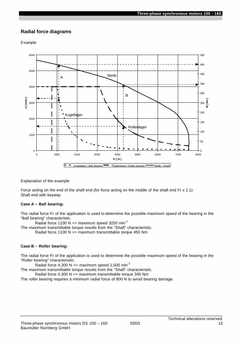
Three-phase synchronous motors 100 - 160
Technical alterations reserved Three-phase synchronous motors DS 100 – 160 03/03 13 Baumüller Nürnberg GmbH
Radial force diagrams Example
0
1000
2000
3000
4000
5000
6000
0 1000 2000 3000 4000 5000 6000 7000 8000
Fr [ N ]
n [ 1
/min
]
0
50
100
150
200
250
300
350
400
450
500
M [
Nm
]
Kugellager / Ball bearing Rollenlager / Roller bearing Welle / Shaft
A
B
Welle
Kugellager
Rollenlager
Explanation of the example Force acting on the end of the shaft end (for force acting on the middle of the shaft end Fr x 1.1) Shaft end with keyway Case A – Ball bearing: The radial force Fr of the application is used to determine the possible maximum speed of the bearing in the “Ball bearing” characteristic.
Radial force 1100 N => maximum speed 3250 min-1
The maximum transmittable torque results from the “Shaft” characteristic. Radial force 1100 N => maximum transmittable torque 450 Nm
Case B – Roller bearing: The radial force Fr of the application is used to determine the possible maximum speed of the bearing in the “Roller bearing” characteristic.
Radial force 4,300 N => maximum speed 1,500 min-1
The maximum transmittable torque results from the “Shaft” characteristic. Radial force 4,300 N => maximum transmittable torque 345 Nm
The roller bearing requires a minimum radial force of 800 N to avoid bearing damage.
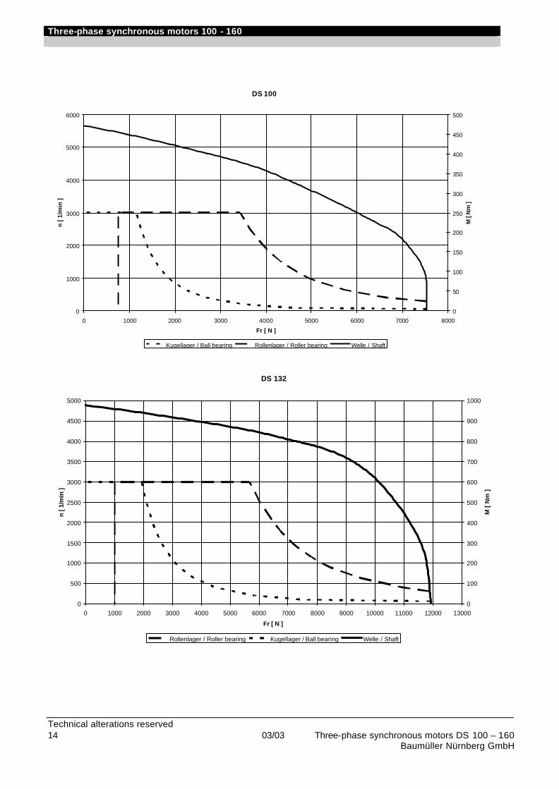
Three-phase synchronous motors 100 - 160
Technical alterations reserved 14 03/03 Three-phase synchronous motors DS 100 – 160 Baumüller Nürnberg GmbH
DS 100
0
1000
2000
3000
4000
5000
6000
0 1000 2000 3000 4000 5000 6000 7000 8000
Fr [ N ]
n [
1/m
in ]
0
50
100
150
200
250
300
350
400
450
500
M [
Nm
]
Kugellager / Ball bearing Rollenlager / Roller bearing Welle / Shaft
DS 132
0
500
1000
1500
2000
2500
3000
3500
4000
4500
5000
0 1000 2000 3000 4000 5000 6000 7000 8000 9000 10000 11000 12000 13000
Fr [ N ]
n [ 1
/min
]
0
100
200
300
400
500
600
700
800
900
1000
M [
Nm
]
Rollenlager / Roller bearing Kugellager / Ball bearing Welle / Shaft
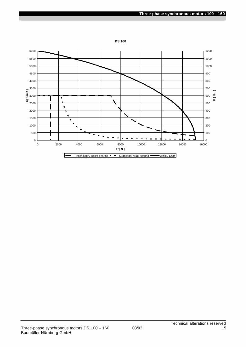
Three-phase synchronous motors 100 - 160
Technical alterations reserved Three-phase synchronous motors DS 100 – 160 03/03 15 Baumüller Nürnberg GmbH
DS 160
0
500
1000
1500
2000
2500
3000
3500
4000
4500
5000
5500
6000
0 2000 4000 6000 8000 10000 12000 14000 16000
Fr [ N ]
n [ 1
/min
]
0
100
200
300
400
500
600
700
800
900
1000
1100
1200
M [
Nm
]
Rollenlager / Roller bearing Kugellager / Ball bearing Welle / Shaft
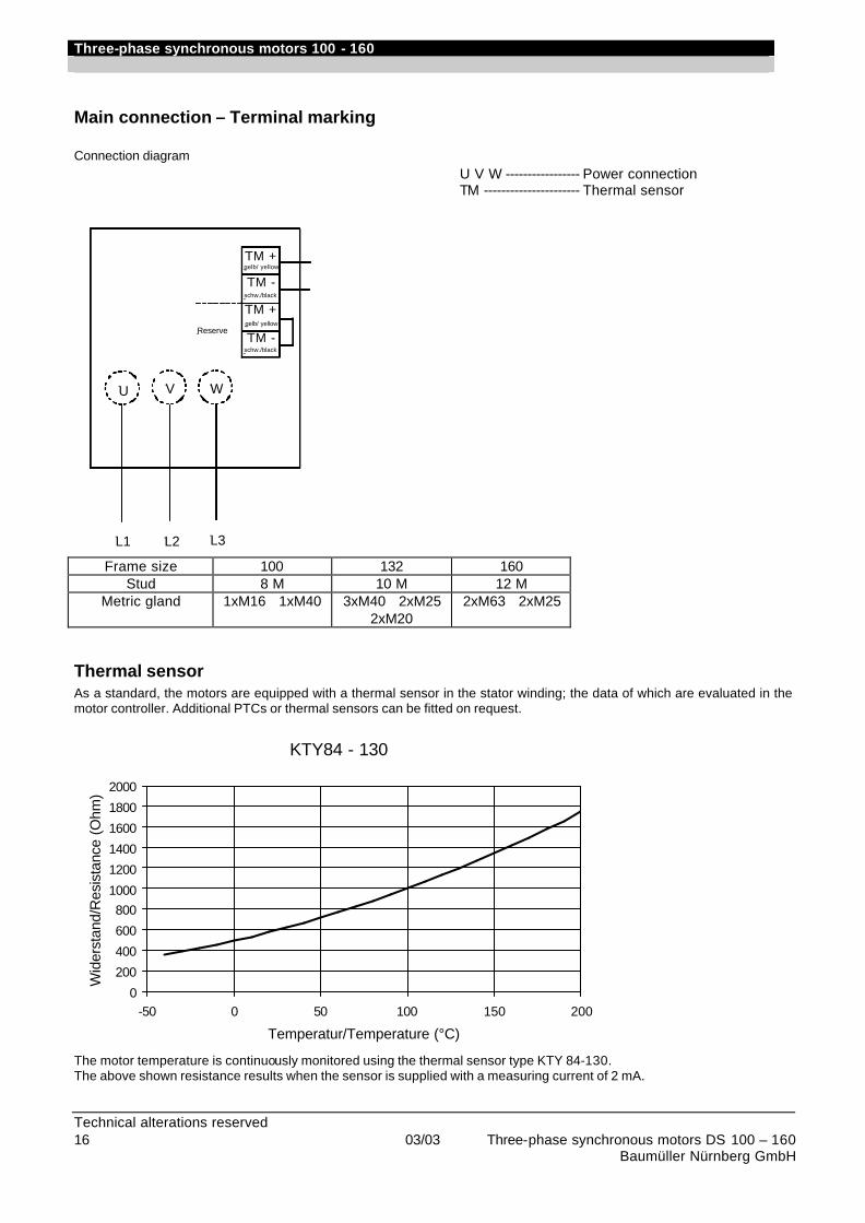
Three-phase synchronous motors 100 - 160
Technical alterations reserved 16 03/03 Three-phase synchronous motors DS 100 – 160 Baumüller Nürnberg GmbH
Main connection – Terminal marking Connection diagram
U V W ----------------- Power connection TM ---------------------- Thermal sensor
Frame size 100 132 160 Stud 8 M 10 M 12 M
Metric gland 1xM16 1xM40 3xM40 2xM25 2xM20
2xM63 2xM25
Thermal sensor As a standard, the motors are equipped with a thermal sensor in the stator winding; the data of which are evaluated in the motor controller. Additional PTCs or thermal sensors can be fitted on request.
KTY84 - 130
0
200
400
600
8001000
1200
1400
1600
1800
2000
-50 0 50 100 150 200
Temperatur/Temperature (°C)
Wid
erst
and/
Res
ista
nce
(Ohm
)
The motor temperature is continuously monitored using the thermal sensor type KTY 84-130. The above shown resistance results when the sensor is supplied with a measuring current of 2 mA.
L1
U
L2 L3
V W
TM -
TM +
Reservegelb/ yellow
schw./black
TM +
TM -schw./black
gelb/ yellow

Three-phase synchronous motors 100 - 160
Technical alterations reserved Three-phase synchronous motors DS 100 – 160 03/03 17 Baumüller Nürnberg GmbH
Noise intensity The ventilated motors do not exceed the noise intensity specified in EN 60034. The values of unventilated motors are clearly lower.
Vibration severityVibration severity
Speed Frame size
100-132 160 [ min-1 ] Veff[mm/s]
N 600 - 1800 (normal) > 1800 1.8 2.8
R* 600 - 1800 0.71 1.12 (reduced) > 1800 1.12 1.8
S* 600 - 1800 0.45 0.71 (special) > 1800 0.71 1.12
The motors can be supplied in three vibration classes according to DIN ISO 5473. * R and S are available with ball bearings only
Fan data Fan connection via terminal box Connection diagram
U V W------------------Power connection Radial fan Frame size Fan type Nom. current [A] with
Y 100 BFB 398 0.33 132 BFB 519 0.8 160 BFB 635 1.4
The fan motors are dimensioned for ∆/Y 200-265/345-460V 50/60Hz as a standard. Nominal currents are maximum values.

Three-phase synchronous motors 100 - 160
Technical alterations reserved 18 03/03 Three-phase synchronous motors DS 100 – 160 Baumüller Nürnberg GmbH
Brake assignment for
motor type
Brake type
Brake torque Input power
max. perm. switching energy
Wperm. per switching operation
Switch-ing
power Pperm.
Disen-gaging time
En-gaging time
Inertia max. perm. speed
Weight
[Nm] [W] [J] [kJ/h] [s] [ms] [kgm²] [min-1] [kg] Operat-
ing brake
Holding brake
Peak load brake
Operat-ing
brake
Holding brake
Peak load brake
for ope-rating brake
Switch-ing ope-ration
Indiv. brakin
g
Indiv. braking
[M2] [M4] [M4] DS..100 SB 50 30 50 - 80 4500 10000 - 470 120 160 0.0005 4000 5 DS..100 SB 100 60 100 60 106 5000 18000 70000 560 180 250 0.0015 3500 9.5 DS..132 SB 200 135 200 140 170 8000 20000 90000 630 225 300 0.0040 3000 13 DS..160 On request
For use as a holding brake the following must be observed: Brake has a considerably increased brake torque 3 emergency stops (individual braking operations) per hour possible if evenly distributed Switching times values are valid for switching on the AC side, in a cold state, with basic air gap and holding brake Disengaging time – Time until the brake has completely disengaged (brake without torque) Engaging time – Time until the brake torque is reached M2 ... dynamic torque, M4 ... static torque All information are valid for the installation on a horizontal shaft The supplier must be contacted before vertical installation. Requirements other than those indicated on request. Braking time / switching energy / switching capacity It is useful to check that the brake is suited for its application. To do this, the brake energy and braking power must be determined. Determination of the braking time [tB]
tB sint
)M(M*9,55?n*J
t 0LB
B +±
∑=
∑J Total moment of inertia in kgm² = Jmot + Jadd (referred to motor shaft) Jmot Motor moment of inertia in kgm² Jadd Additional moment of inertia in kgm² (referred to motor shaft) ?n Motor speed in min-1
MB Brake torque in Nm ML Load torque in Nm (positively calculated if it decelerates, negatively calculated if it accelerates) t0 Time in s from the switching instant to the full extent of the braking torque (response time) i Number of cycles per hour Determining the switching energy [WR] Determining the switching capacity [PR]
operation switchingJoule
in )M(M
M182.4
nJW
LB
B2
?R ±
⋅⋅∑
= h
kJ in
1000iW
P RR
⋅=
WRperm ≤ value from table PRperm ≤ Value from table In most cases, t0 is negligible. If this is not the case and the time t0 must be reduced, you can achieve this by interrupting the magnet circuit on the DC side. However, this measure must be known before dimensioning the brake motor. Brake supply Normal voltage: 24; 96 - 120; 176V- (other voltages on request), 24 V: Supply with transformer and rectifier, 96 – 120 and 176 V: Supply using brake supply unit The brakes can alternatively be equipped with microswitch or mechanical ventilation. Switching capacity of microswitches Ohmic load up to 30 V DC - 5 A or 250 V AC - 5 A; inductive load up to 30 V DC -3 A or 250 V AC -2 A The contact ratings apply to silver contacts
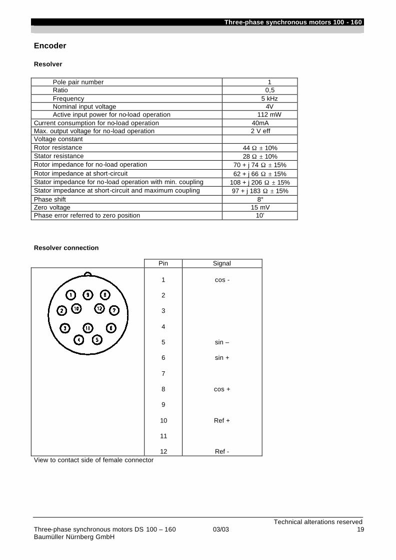
Three-phase synchronous motors 100 - 160
Technical alterations reserved Three-phase synchronous motors DS 100 – 160 03/03 19 Baumüller Nürnberg GmbH
Encoder
Resolver
Pole pair number 1 Ratio 0,5 Frequency 5 kHz Nominal input voltage 4V Active input power for no-load operation 112 mW
Current consumption for no-load operation 40mA Max. output voltage for no-load operation 2 V eff Voltage constant Rotor resistance 44 Ω ± 10% Stator resistance 28 Ω ± 10% Rotor impedance for no-load operation 70 + j 74 Ω ± 15% Rotor impedance at short-circuit 62 + j 66 Ω ± 15% Stator impedance for no-load operation with min. coupling 108 + j 206 Ω ± 15% Stator impedance at short-circuit and maximum coupling 97 + j 183 Ω ± 15% Phase shift 8° Zero voltage 15 mV Phase error referred to zero position 10’
Resolver connection
View to contact side of female connector
Pin Signal
1
2
3
4
5
6
7
8
9
10
11
12
cos -
sin –
sin +
cos +
Ref +
Ref -
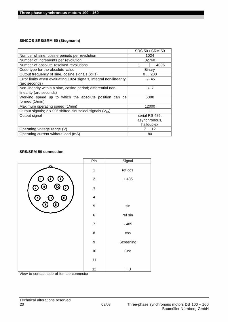
Three-phase synchronous motors 100 - 160
Technical alterations reserved 20 03/03 Three-phase synchronous motors DS 100 – 160
Baumüller Nürnberg GmbH
SINCOS SRS/SRM 50 (Stegmann) SRS 50 / SRM 50 Number of sine, cosine periods per revolution 1024 Number of increments per revolution 32768 Number of absolute resolved revolutions 1 4096 Code type for the absolute value Binary Output frequency of sine, cosine signals (kHz) 0 ... 200 Error limits when evaluating 1024 signals, integral non-linearity (arc seconds)
+/- 45
Non-linearity within a sine, cosine period; differential non-linearity (arc seconds)
+/- 7
Working speed up to which the absolute position can be formed (1/min)
6000
Maximum operating speed (1/min) 12000 Output signals; 2 x 90° shifted sinusoidal signals (Vpp) 1 Output signal serial RS 485,
asynchronous, halfduplex
Operating voltage range (V) 7 ... 12 Operating current without load (mA) 80 SRS/SRM 50 connection
Pin Signal
1
2
3
4
5
6
7
8
9
10
11
12
ref cos
+ 485
sin
ref sin
- 485
cos
Screening
Gnd
+ U View to contact side of female connector
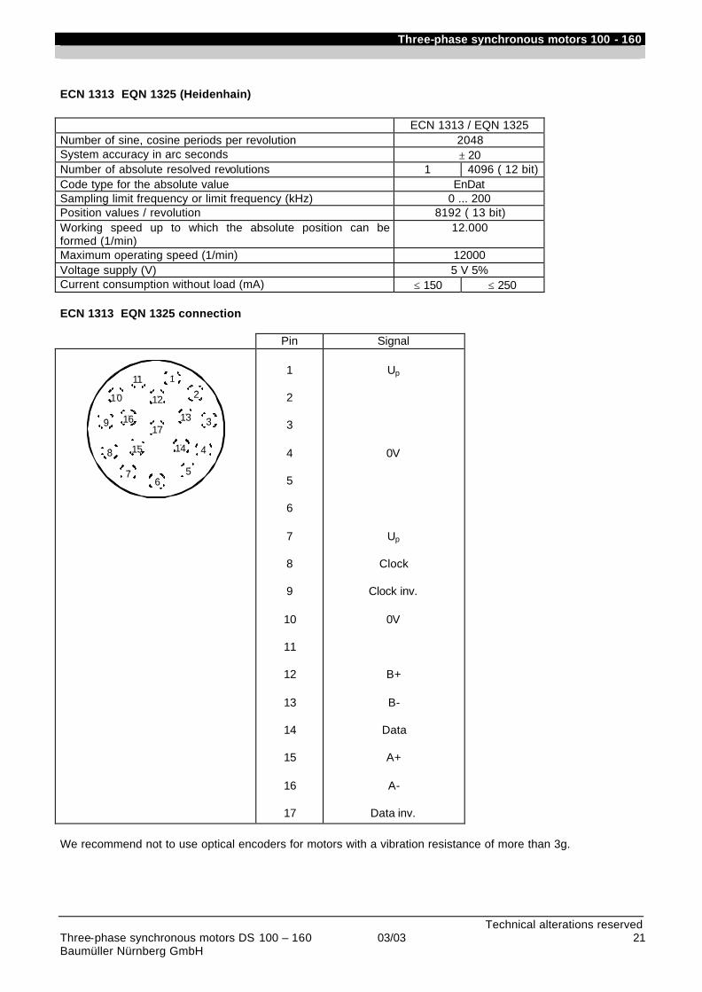
Three-phase synchronous motors 100 - 160
Technical alterations reserved Three-phase synchronous motors DS 100 – 160 03/03 21 Baumüller Nürnberg GmbH
ECN 1313 EQN 1325 (Heidenhain) ECN 1313 / EQN 1325 Number of sine, cosine periods per revolution 2048 System accuracy in arc seconds ± 20 Number of absolute resolved revolutions 1 4096 ( 12 bit) Code type for the absolute value EnDat Sampling limit frequency or limit frequency (kHz) 0 ... 200 Position values / revolution 8192 ( 13 bit) Working speed up to which the absolute position can be formed (1/min)
12.000
Maximum operating speed (1/min) 12000 Voltage supply (V) 5 V 5% Current consumption without load (mA) ≤ 150 ≤ 250 ECN 1313 EQN 1325 connection
Pin Signal
8
10
9
2
576
111
131617
12
1415
3
4
1
2
3
4
5
6
7
8
9
10
11
12
13
14
15
16
17
Up
0V
Up
Clock
Clock inv.
0V
B+
B-
Data
A+
A-
Data inv.
We recommend not to use optical encoders for motors with a vibration resistance of more than 3g.

Three-phase synchronous motors 100 - 160
Technical alterations reserved 22 03/03 Three-phase synchronous motors DS 100 – 160
Baumüller Nürnberg GmbH
Dimension drawings
DS 100 / 132 / 160 IP 23 internally ventilated
k = without brake k2 = with encoder k3 = with brake k4 = with encoder and brake i6 = Centring with internal thread acc. to DIN 332 form D
Type Foot Motor
a b c e f s w1 g g1 g2 g3 g7 g11 g12 h k k2 k3 k4 p p1 p4 q* q q1 q2 q5
100 K 273 160 10 330 200 12 50 220 190 172 220 108 78 10 100 480 600 578 698 210 320 215 283 310 451 230 181 100 M 323 380 530 650 628 748 360 501 100 L 373 430 580 700 678 798 410 551 100 B 423 480 630 750 728 848 460 601 132 K 365 216 12 423 264 12 63 285 285 213 265 125 102 15 132 595 715 703 823 270 395 264 338 373 550 311 250 132 M 415 473 645 765 753 873 423 600 132 L 465 523 695 815 803 923 473 650 132 B 515 573 745 865 853 973 523 700 160 K 464 254 12 508 312 14 70 340 276 237 295 145 114 19 160 738 858 888 1008 324 450 297 380 504 667 339 280 160 M 514 558 788 908 938 1058 554 717 160 L 564 608 838 958 988 1108 604 767 160 B 614 658 888 1008 1038 1158 654 817 Version IM B3 Type of protection IP 23 Cooling method IC
06
Type Shaft Motor d l t u i6 y y1 S2
100 42 110 45 12 M16 150 135 1M40 1M16
132 55 110 59 16 M20 235 235 3M40 2M25 2M20
160 60 140 64 18 M20 252 252 2M63 2M25

Three-phase synchronous motors 100 - 160
Technical alterations reserved Three-phase synchronous motors DS 100 – 160 03/03 23 Baumüller Nürnberg GmbH
DS 100 / 132 IP 54 surface-cooled
k = without brake k2 = with encoder k3 = with brake k4 = with encoder and brake i6 = Centring with internal thread acc. to DIN 332 form D
Type Shaft Motor
d l t u i6 y y1 S2 100 42 110 45 12 M16 150 135 1M40
1M16 132 55 110 59 16 M20 235 235 3M40
2M25 2M20
Type Foot Motor a b c e f s w1 g g1 g2 g3 g7 g11 g12* g13 h k k2 k3 k4 p p1 p4 q* q q1* q2 q5
100 K 273 160 10 330 200 12 50 220 190 172 220 108 78 8 260 100 480 600 578 698 210 320 215 283 310 451 230 181 100 M 323 380 530 650 628 748 360 501 100 L 373 430 580 700 678 798 410 551 100 B 423 480 630 750 728 848 460 601 132 K 365 216 12 423 264 12 63 285 276 213 265 125 102 10 324 132 595 715 703 823 270 395 264 338 373 557 311 250 132 M 415 473 645 765 753 873 423 607 132 L 465 523 695 815 803 923 473 657 132 B 515 573 745 865 853 973 523 707
Version IM B3 Type of protection IP 54 Cooling method IC
06
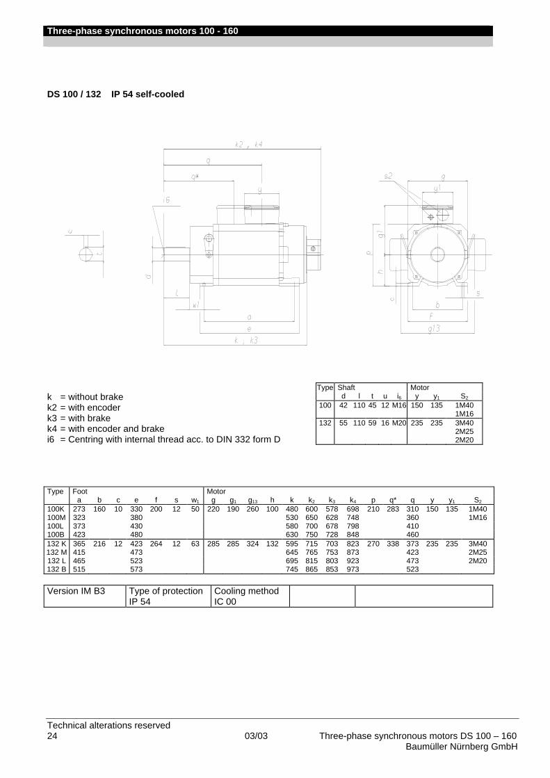
Three-phase synchronous motors 100 - 160
Technical alterations reserved 24 03/03 Three-phase synchronous motors DS 100 – 160
Baumüller Nürnberg GmbH
DS 100 / 132 IP 54 self-cooled
k = without brake k2 = with encoder k3 = with brake k4 = with encoder and brake i6 = Centring with internal thread acc. to DIN 332 form D
Type Foot Motor a b c e f s w1 g g1 g13 h k k2 k3 k4 p q* q y y1 S2
100K 273 160 10 330 200 12 50 220 190 260 100 480 600 578 698 210 283 310 150 135 1M40 100M 323 380 530 650 628 748 360 1M16 100L 373 430 580 700 678 798 410 100B 423 480 630 750 728 848 460 132 K 365 216 12 423 264 12 63 285 285 324 132 595 715 703 823 270 338 373 235 235 3M40 132 M 415 473 645 765 753 873 423 2M25 132 L 465 523 695 815 803 923 473 2M20 132 B 515 573 745 865 853 973 523 Version IM B3 Type of protection
IP 54 Cooling method IC 00
Type Shaft Motor d l t u i6 y y1 S2
100 42 110 45 12 M16 150 135 1M40 1M16
132 55 110 59 16 M20 235 235 3M40 2M25 2M20
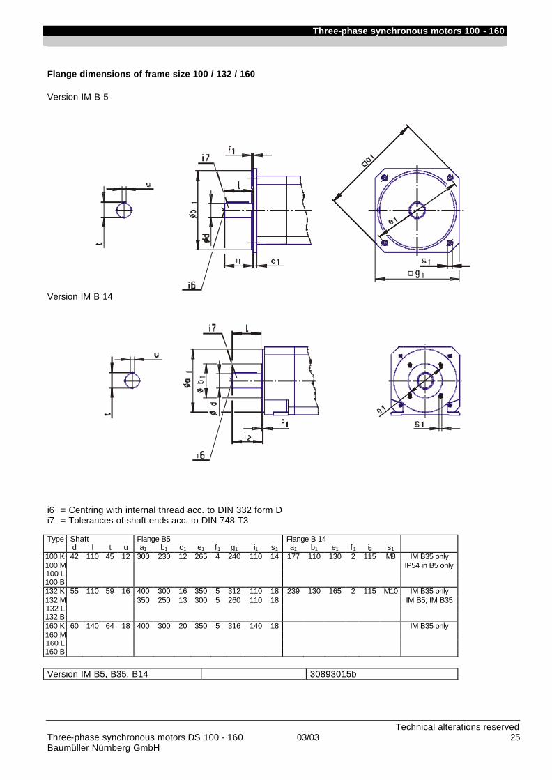
Three-phase synchronous motors 100 - 160
Technical alterations reserved Three-phase synchronous motors DS 100 - 160 03/03 25 Baumüller Nürnberg GmbH
Flange dimensions of frame size 100 / 132 / 160 Version IM B 5
Version IM B 14
i6 = Centring with internal thread acc. to DIN 332 form D i7 = Tolerances of shaft ends acc. to DIN 748 T3 Type Shaft Flange B5 Flange B 14
d l t u a1 b1 c1 e1 f1 g1 i1 s1 a1 b1 e1 f1 i2 s1
100 K 42 110 45 12 300 230 12 265 4 240 110 14 177 110 130 2 115 M8 IM B35 only 100 M IP54 in B5 only 100 L 100 B 132 K 55 110 59 16 400 300 16 350 5 312 110 18 239 130 165 2 115 M10 IM B35 only 132 M 350 250 13 300 5 260 110 18 IM B5; IM B35 132 L 132 B 160 K 60 140 64 18 400 300 20 350 5 316 140 18 IM B35 only 160 M 160 L 160 B Version IM B5, B35, B14 30893015b
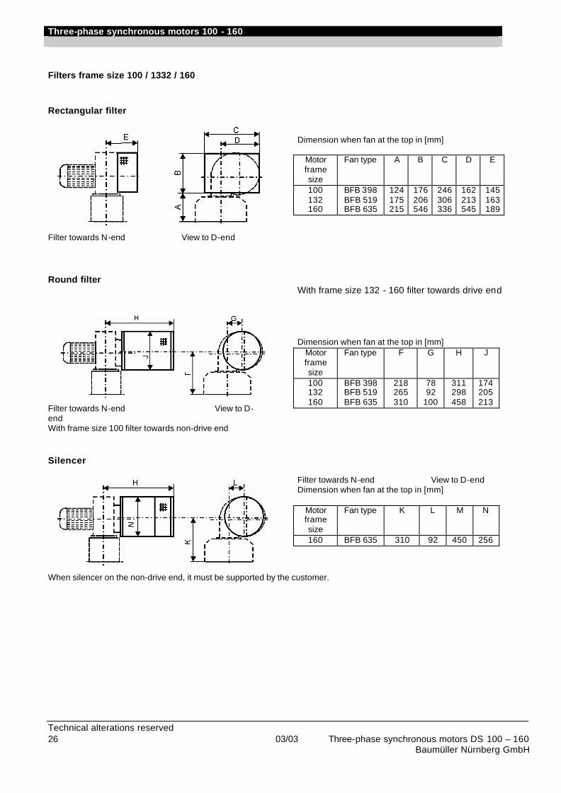
Three-phase synchronous motors 100 - 160
Technical alterations reserved 26 03/03 Three-phase synchronous motors DS 100 – 160
Baumüller Nürnberg GmbH
Filters frame size 100 / 1332 / 160 Rectangular filter Filter towards N-end View to D-end
Dimension when fan at the top in [mm]
Motor frame size
Fan type A B C D E
100 BFB 398 124 176 246 162 145 132 BFB 519 175 206 306 213 163 160 BFB 635 215 546 336 545 189
Round filter Filter towards N-end View to D-end With frame size 100 filter towards non-drive end
With frame size 132 - 160 filter towards drive end Dimension when fan at the top in [mm]
Motor frame size
Fan type F G H J
100 BFB 398 218 78 311 174 132 BFB 519 265 92 298 205 160 BFB 635 310 100 458 213
Silencer
Filter towards N-end View to D-end Dimension when fan at the top in [mm]
Motor frame size
Fan type K L M N
160 BFB 635 310 92 450 256
When silencer on the non-drive end, it must be supported by the customer.
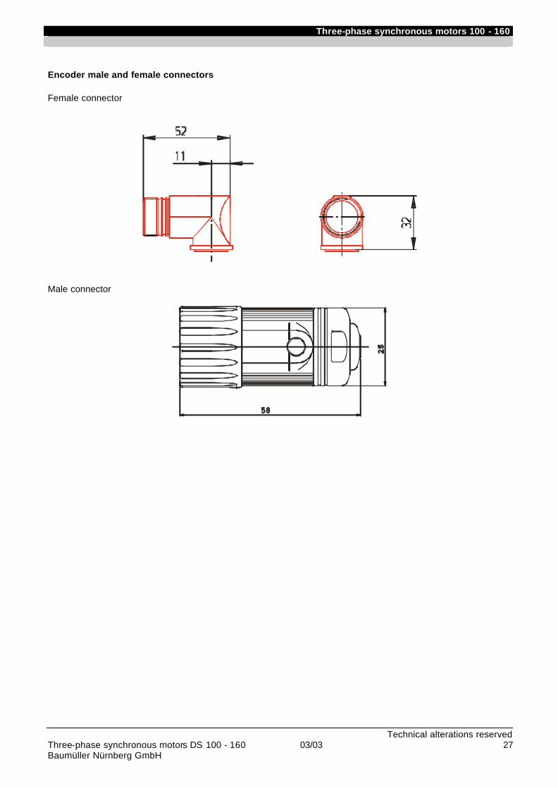
Three-phase synchronous motors 100 - 160
Technical alterations reserved Three-phase synchronous motors DS 100 - 160 03/03 27 Baumüller Nürnberg GmbH
Encoder male and female connectors Female connector
Male connector
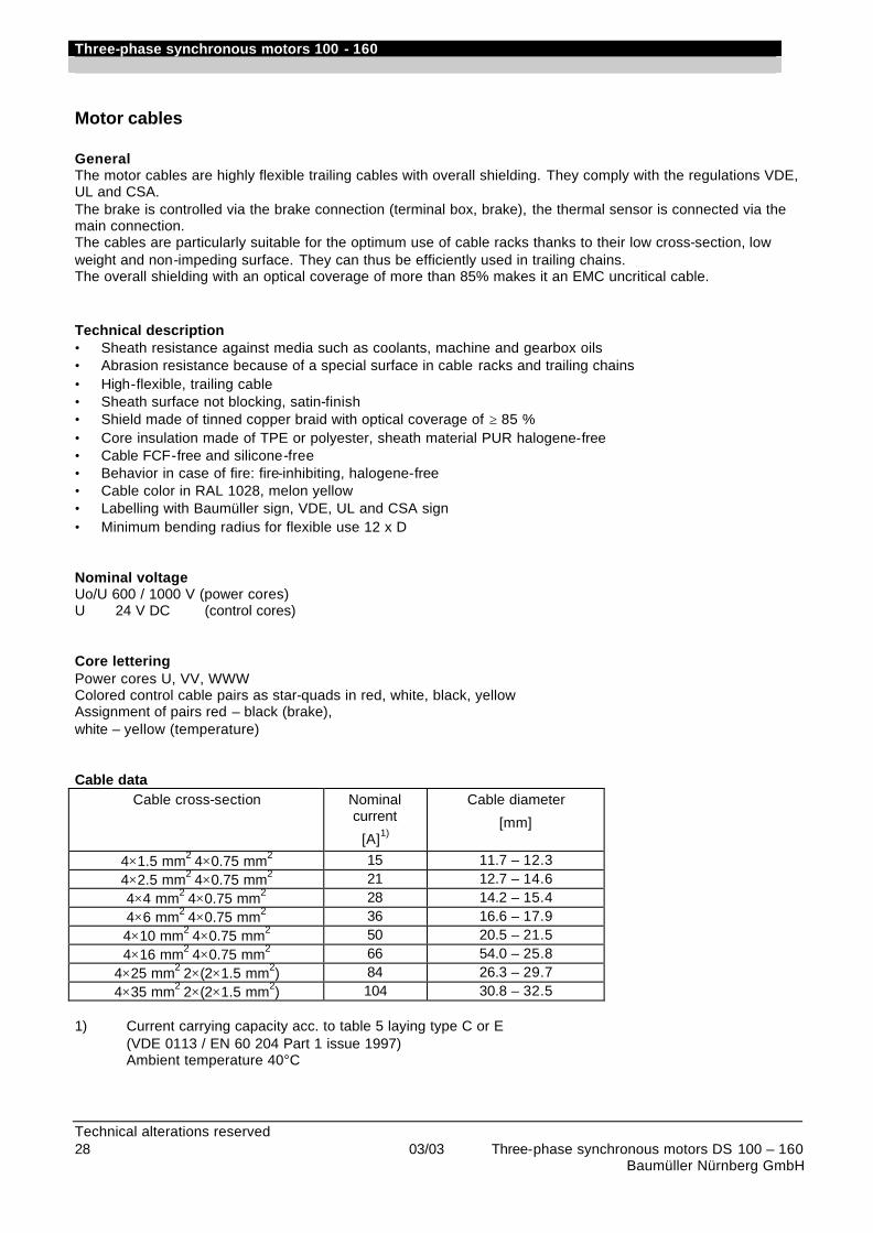
Three-phase synchronous motors 100 - 160
Technical alterations reserved 28 03/03 Three-phase synchronous motors DS 100 – 160 Baumüller Nürnberg GmbH
Motor cables General The motor cables are highly flexible trailing cables with overall shielding. They comply with the regulations VDE, UL and CSA. The brake is controlled via the brake connection (terminal box, brake), the thermal sensor is connected via the main connection. The cables are particularly suitable for the optimum use of cable racks thanks to their low cross-section, low weight and non-impeding surface. They can thus be efficiently used in trailing chains. The overall shielding with an optical coverage of more than 85% makes it an EMC uncritical cable. Technical description • Sheath resistance against media such as coolants, machine and gearbox oils • Abrasion resistance because of a special surface in cable racks and trailing chains • High-flexible, trailing cable • Sheath surface not blocking, satin-finish • Shield made of tinned copper braid with optical coverage of ≥ 85 % • Core insulation made of TPE or polyester, sheath material PUR halogene-free • Cable FCF-free and silicone-free • Behavior in case of fire: fire-inhibiting, halogene-free • Cable color in RAL 1028, melon yellow • Labelling with Baumüller sign, VDE, UL and CSA sign • Minimum bending radius for flexible use 12 x D Nominal voltage Uo/U 600 / 1000 V (power cores) U 24 V DC (control cores) Core lettering Power cores U, VV, WWW Colored control cable pairs as star-quads in red, white, black, yellow Assignment of pairs red – black (brake), white – yellow (temperature) Cable data
Cable cross-section Nominal current
[A]1)
Cable diameter
[mm]
4×1.5 mm2 4×0.75 mm2 15 11.7 – 12.3 4×2.5 mm2 4×0.75 mm2 21 12.7 – 14.6 4×4 mm2 4×0.75 mm2 28 14.2 – 15.4 4×6 mm2 4×0.75 mm2 36 16.6 – 17.9 4×10 mm2 4×0.75 mm2 50 20.5 – 21.5 4×16 mm2 4×0.75 mm2 66 54.0 – 25.8
4×25 mm2 2×(2×1.5 mm2) 84 26.3 – 29.7 4×35 mm2 2×(2×1.5 mm2) 104 30.8 – 32.5
1) Current carrying capacity acc. to table 5 laying type C or E
(VDE 0113 / EN 60 204 Part 1 issue 1997) Ambient temperature 40°C
Three-phase synchronous motors 100 - 160
Technical alterations reserved Three-phase synchronous motors DS 100 - 160 03/03 29 Baumüller Nürnberg GmbH
Cables of 1.5 / 2.5 mm2 can be laid up to 100 m without additional filters, when larger cross-sections used, cable lengths up to 40 m are permissible. The terminal voltage at the motor must be < 1kV, however. If the terminal voltages exceed 1 kV, filters must be installed between converter and motor. Application notes Operating temperature The cables can be operated within a temperature range from –20°C to +80°C. Cable laying at the motor The cables must not touch the motor surface. Smallest permissible bending radii 12 times outer cable diameter. Smaller bending radii are possible with reduced service life.
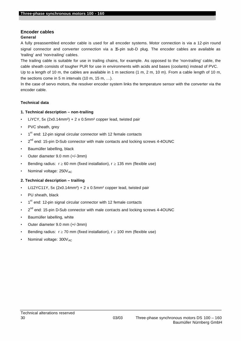
Three-phase synchronous motors 100 - 160
Technical alterations reserved 30 03/03 Three-phase synchronous motors DS 100 – 160 Baumüller Nürnberg GmbH
Encoder cables General A fully preassembled encoder cable is used for all encoder systems. Motor connection is via a 12-pin round
signal connector and converter connection via a 15-pin sub-D plug. The encoder cables are available as 'trailing' and 'non-trailing' cables. The trailing cable is suitable for use in trailing chains, for example. As opposed to the 'non-trailing' cable, the cable sheath consists of tougher PUR for use in environments with acids and bases (coolants) instead of PVC. Up to a length of 10 m, the cables are available in 1 m sections (1 m, 2 m, 10 m). From a cable length of 10 m,
the sections come in 5 m intervals (10 m, 15 m, …). In the case of servo motors, the resolver encoder system links the temperature sensor with the converter via the encoder cable.
Technical data 1. Technical description – non-trailing
• LiYCY, 5x (2x0.14mm²) + 2 x 0.5mm² copper lead, twisted pair
• PVC sheath, grey
• 1st end: 12-pin signal circular connector with 12 female contacts
• 2nd end: 15-pin D-Sub connector with male contacts and locking screws 4-4OUNC
• Baumüller labelling, black
• Outer diameter 9.0 mm (+/-3mm)
• Bending radius: r ≥ 60 mm (fixed installation), r ≥ 135 mm (flexible use)
• Nominal voltage: 250VAC 2. Technical description – trailing
• Li12YC11Y, 5x (2x0.14mm²) + 2 x 0.5mm² copper lead, twisted pair
• PU sheath, black
• 1st end: 12-pin signal circular connector with 12 female contacts
• 2nd end: 15-pin D-Sub connector with male contacts and locking screws 4-4OUNC
• Baumüller labelling, white
• Outer diameter 9.0 mm (+/-3mm)
• Bending radius: r ≥ 70 mm (fixed installation), r ≥ 100 mm (flexible use)
• Nominal voltage: 300VAC
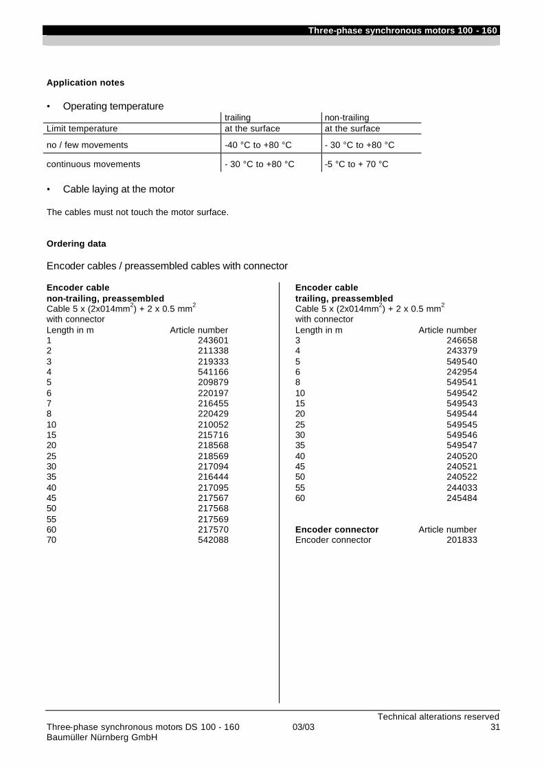
Three-phase synchronous motors 100 - 160
Technical alterations reserved Three-phase synchronous motors DS 100 - 160 03/03 31 Baumüller Nürnberg GmbH
Application notes • Operating temperature trailing non-trailing Limit temperature at the surface at the surface
no / few movements -40 °C to +80 °C - 30 °C to +80 °C
continuous movements - 30 °C to +80 °C -5 °C to + 70 °C • Cable laying at the motor The cables must not touch the motor surface. Ordering data Encoder cables / preassembled cables with connector Encoder cable non-trailing, preassembled Cable 5 x (2x014mm2) + 2 x 0.5 mm2 with connector Length in m Article number 1 243601 2 211338 3 219333 4 541166 5 209879 6 220197 7 216455 8 220429 10 210052 15 215716 20 218568 25 218569 30 217094 35 216444 40 217095 45 217567 50 217568 55 217569 60 217570 70 542088
Encoder cable trailing, preassembled Cable 5 x (2x014mm2) + 2 x 0.5 mm2 with connector Length in m Article number 3 246658 4 243379 5 549540 6 242954 8 549541 10 549542 15 549543 20 549544 25 549545 30 549546 35 549547 40 240520 45 240521 50 240522 55 244033 60 245484 Encoder connector Article number Encoder connector 201833
Three-phase synchronous motors 100 - 160
Technical alterations reserved 32 03/03 Three-phase synchronous motors DS 100 – 160
Baumüller Nürnberg GmbH
Commissioning and maintenance instructions Please contact us for our commissioning and maintenance instructions for motor commissioning.
Headquater: Baumüller Nürnberg GmbH • Ostendstraße 80-90 • D-90482 Nürnberg Tel +49 (0)911 5432 -0 • Fax +49 (0)911 5432 -130 • http://www.baumueller.de
Drive Center National
Darmstadt Baumüller Griesheim GmbH & Co. KG Waldstraße 1 • D-64347 Griesheim Tel +49- (0)6155 8430-00 • Fax +49- (0)6155 8430-20
Düsseldorf Baumüller Nürnberg GmbH Jacob-Kaiser-Str. 7 • D-47877 Willich-Münchheide Tel +49- (0)2154-487-0 • Fax +49- (0)2154-487-59
Dresden Baumüller Kamenz GmbH Nordstraße 57 • D-01917 Kamenz Tel +49- (0)3578 3406-0 • Fax +49- (0)3578 3406-50
Hannover Baumüller Nürnberg GmbH Bohlenweg 10 • D-30853 Langenhagen Tel +49-(0)511 771968-0 • Fax +49- 0)511 771968-77
Nürnberg Baumüller Nürnberg GmbH Ostendstr. 80-90 • D-90482 Nürnberg Tel +49- (0)911-5432-501 • Fax +49- (0)911-5432-510
Stuttgart Baumüller Griesheim GmbH & Co. KG Hahnweidstr. 21• D-73230 Kirchheim / Teck Tel +49- (0)7021-48557-10 • Fax +49-(0)7021-48557-77
Drive Center International
Australia / Sydney Baumüller Australia Pty. Ltd. Unit 4, 476 Gardeners Road Alexandria NSW 2015, Australia Tel +61 2 8338-0386 • Fax +61 2 8338-0389
Australia / Melbourne Baumüller Australia Pty. Ltd. 45 Jarrah Drive • Braeside Vic. 3195, Australia Tel +61 3 9580-9522 • Fax +61 3 9587-3886
Austria Baumüller Austria Ges.mbH Im Bäckerfeld 17 • A-4060 Leonding Tel +43 (0)732 674414-0 • Fax +43 (0)732 674414-32
China / Hong Kong Baumüller Australia Pty. Ltd. 13H, Block 4, Carado Garden, Tai Wai • N.T., Hong Kong Tel/ Fax +852 2695-9755 Handy +852 9194-1582
England Baumüller (UK) Ltd. 14 Redlands Centre • GB-Coulsdon, Surrey CR5 2HT Tel +44(0)208 76329-90 • Fax +44(0)208 76329-59
France Baumüller France S.à.r.l. Zone de la Malnoue 39, Avenue de l´Europe • F- 77184 Emerainville Tel +33 1 6461-6622 • Fax +33 1 6461-6006
India Baumüller KAT India Pvt. Ltd. Dattaprasad Apartment • Flat No. 7, 3Rd Floor, B/7, 1206, APTE Road • IND- 411 004 Pune Tel +91 20 5513311 • Fax +91 20 5513388
Italy Baumüller Italia s.r.l., Viale Italia, 12 • I-20094 Corsico (Mi), Tel +39 02 45100-181 • Fax +39 02 45100-426
Slowenia Baumüller Dravinja d.o.o. Delavska cesta 10 • SI-3210 Slovenske- Konjice Tel +386 3-75723-00 • Fax +386 3-75723-32/33
Switzerland Baumüller Suisse S.A. Rue des Usines 22 • CH-2000 Neuchâtel Tel +41 (0)32 7301-260 • Fax +41 (0)32 7301-351
The Netherlands Baumüller Benelux B.V. Platinastraat 141 • NL-2718 SR Zoetermeer Tel +31(0)79-3614-290 • Fax +31(0)79-3614-339
Turkey BAUMÜLLER MOTOR KONTROL SISTEM SAN. VE TIC. LTD. STI Colak Ismail Sok., No:31/1 • TR-81070 Istanbul-Suadiye Tel +90 (0)216 372-2485 • Fax +90 (0)216 372-7570
USA Baumueller Hartford Inc. 117 West Dudley Town Road • USA-Bloomfield, CT 06002 Tel +1 860 -243 0232 • Fax +1 860 -286 3080
USA Baumueller Chicago Corp. 405 Algonquin Rd. • USA-Mount Prospect, Ill 60056 Tel +1 847 956-7392 • Fax +1 847 956-7925
Representatives International
Brasil NC SERVICE INDÚSTRIA E COMÉRCIO LTDA. Av. Juruá, 150, - Barueri - SP • BR- 06455 - 010 Tel +55 (0)11 4195-0502 • Fax +55 (0)11 4195-2479
Czech Rep. ATEM CNC- TECHNIK spol.s.r.o. V domove 4 • CZ- 130 00 Praha 3 Tel u. Fax +420 222587698
Hungary MELTRON KFT. Gyömroi ut. 128. • H-1103 Budapest Tel/ Fax +36 1 264 - 9482
Iran PAK GOSTAR Co. 502, 5th Floor, BORJ-E SEFID, PASDARAN Ave TEHRAN - IRAN Tel +98 21 2553868-70 • Fax + +98 21 2547703
Japan NUSCO CO Ltd. 6-17-8 Nagayama, Tama, Tokyo • J- 206-0025 Tel +81 (0)423 73-1621 • Fax +81 (0)423 73-1821
Korea BOMAC SYSTEMS 712 Yucheon Factophia • 196 Anyang-7 dong, Mananku, Anyangsi, • Kyungkido 430-017, Korea Tel +82 31 467-2030 • Fax +82 31 467-2033
Poland MECTEC POLSKA Ul. Mickiewicza 19 • PL-60833 Poznan Tel. / Fax +48 (0)61 - 8470553
Russia Elektroprivod J.-s. st. Sadovaja- Spaskaja h. 1/2, b.2 • Moscow ,107078 Tel +7 (0)95 2082-160 • Fax +7 (0)95 2082-623
Spain Ofisistelec, S.L. Poligono Industrial Virgen de los Dolores E-46113 Moncada (Valencia) Tel +34 96 144-5055 • Fax +34 96 144-5311
Sweden OCTAB Industrielektronik AB Maskingatan 8B • SE-195 60 Märsta Tel +46 (8) 591 150-00 • Fax +46 (8) 591 150-01
USA Industrial Drives Design, Inc. 668 Flinn Avenue Unit 28 • USA- Moorpark CA 93021 Tel +1 805 378-1170 • Fax +1 805 378-1171
Venezuela,Columbia,Equador Nimbus International C.A. C.C. Parque Tuy, Local P-18 YV-Ocumare del Tuy 1209 Tel +58(0)39-251347 • Fax +58(0)39-257149
Manufacturing locations
Motors Baumüller Nürnberg GmbH Ostendstraße 80- 90 • D-90482 Nürnberg Tel +49- (0)911-5432-0 • Fax +49- (0)911-5432-130
Baumüller Nürnberg GmbH Werk Kitzingen Floßhafenstraße 2 • D-97318 Kitzingen Tel +49- (0)9321-70080 • Fax +49- (0)9321-700888
Baumüller Brno s.r.o Skalice nad Svitavou 72 CZ- 67901 Skalice nad Svitavou, Tel +420 516-499 111 • Fax +420 516-499 117
Baumüller Kamenz GmbH Nordstraße 57 • D-01917 Kamenz Tel +49- (0)3578 3406-0 • Fax +49- (0)3578 3406-50
Small Motors Baumüller Nürnberg GmbH Werk Bad Gandersheim Flugplatzweg 2 • D-37581 Bad Gandersheim Tel +49- (0)5382 9805-0 • Fax 49- (0)5382 9805-55
Electronics Baumüller Nürnberg Electronic GmbH & Co. Ostendstraße 80- 90 • D-90482 Nürnberg Tel +49- (0)911-5432-293 • Fax +49- (0)911-5432-328
Baumüller Dravinja d.o.o. Delavska cesta 10 • SI-3210 Slovenske- Konjice Tel +386 3-75723-00 • Fax +386 3-75723-32/33
Systems
Baumüller Anlagen-Systemtechnik GmbH & Co. KG Ostendstraße 84 • D-90482 Nürnberg Tel +49- (0)911-54408-0 • Fax +49- (0)911-54408-749
Services
Baumüller Reparaturwerk GmbH & Co KG Andernacher Straße 19 • D-90411 Nürnberg Tel +49- (0)911-9552-0 • Fax+49- (0)911-9552-999 München Baumüller München GmbH Meglingerstraße 58 • D-81477 München Tel +49- (0)89 748898-10 • Fax +49- (0)89 748898-75
!" ## $ % #! $##& ! # &## %! #
'( )(*+,-./-)(%01/23 4/ 501/23 4/