THREE PHASE INDUCTION MOTOR PREMIUM EFFICIENCY IE3 · 2020-03-20 · THREE PHASE INDUCTION MOTOR...
24
For the sake of the planet, motors have their own part to play SUPER LINE P SERIES THREE PHASE INDUCTION MOTOR PREMIUM EFFICIENCY IE3
Transcript of THREE PHASE INDUCTION MOTOR PREMIUM EFFICIENCY IE3 · 2020-03-20 · THREE PHASE INDUCTION MOTOR...
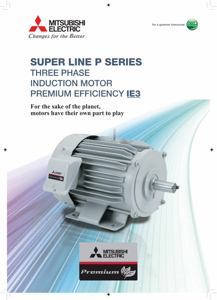
For the sake of the planet, motors have their own part to play
SUPER LINE P SERIESTHREE PHASE INDUCTION MOTORPREMIUM EFFICIENCY IE3

1
Global Player
GLOBAL IMPACT OF MITSUBISHI ELECTRIC
We bring together the best minds to create the best technologies. At Mitsubishi Electric, we understand that technology is the driving force of change in our lives. By bringing greater comfort to daily life, maximizing the efficiency of businesses and keeping things running across society, we integrate technology and innovation to bring changes for the better.
Mitsubishi Electric is involved in many areas including the following
Energy and Electric SystemsA wide range of power and electrical products from generators to large-scale displays.
Electronic DevicesA wide portfolio of cutting-edge semiconductor devices for systems and products.
Home AppliancesDependable consumer products like air conditioners and home entertainment systems.
Information and Communication SystemsCommercial and consumer-centric equipment, products and systems.
Industrial Automation SystemsMaximizing productivity and efficiency with cutting-edge automation technology.
2
Contents
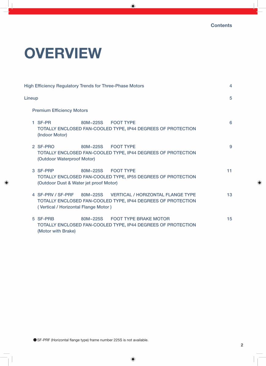
OVERVIEW
4
Lineup 5
1 SF-PR 80M~225S FOOT TYPE 6 TOTALLY ENCLOSED FAN-COOLED TYPE, IP44 DEGREES OF PROTECTION (Indoor Motor)
2 SF-PRO 80M~225S FOOT TYPE 9 TOTALLY ENCLOSED FAN-COOLED TYPE, IP44 DEGREES OF PROTECTION (Outdoor Waterproof Motor)
3 SF-PRP 80M~225S FOOT TYPE 11 TOTALLY ENCLOSED FAN-COOLED TYPE, IP55 DEGREES OF PROTECTION (Outdoor Dust & Water jet proof Motor)
4 SF-PRV / SF-PRF 80M~225S VERTICAL / HORIZONTAL FLANGE TYPE 13 TOTALLY ENCLOSED FAN-COOLED TYPE, IP44 DEGREES OF PROTECTION ( Vertical / Horizontal Flange Motor )
5 SF-PRB 80M~225S FOOT TYPE BRAKE MOTOR 15 TOTALLY ENCLOSED FAN-COOLED TYPE, IP44 DEGREES OF PROTECTION (Motor with Brake)
●SF-PRF (Horizontal �ange type) frame number 225S is not available.
technology, while maintaining the ease of use of general-purpose motors.
With proprietary steel frame technology, Mitsubishi Electric will continue to develop and sell
technology, while maintaining the ease of use of general-purpose motors.
With proprietary steel frame technology, Mitsubishi Electric will continue to develop and sell
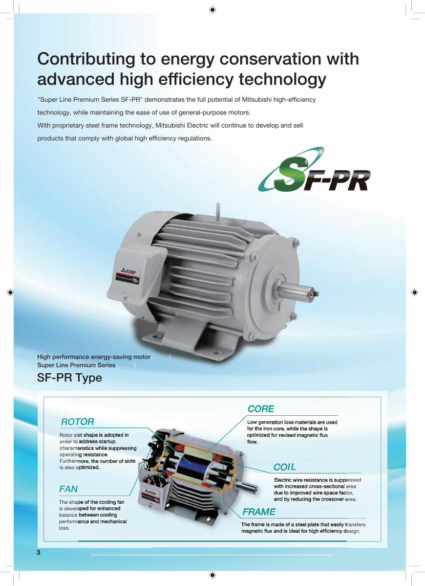
Contributing to energy conservation with
FRAME
ROTORRotor slot shape is adopted in order to address startup characteristics while suppressing operating resistance. Furthermore, the number of slots is also optimized.
FANThe shape of the cooling fan is developed for enhanced balance between cooling performance and mechanical loss.
The frame is made of a steel plate that easily transfers
CORELow generation loss materials are used for the iron core, while the shape is
COILElectric wire resistance is suppressed with increased cross-sectional area due to improved wire space factor, and by reducing the crossover area.
33
High performance energy-saving motor Super Line Premium Series
SF-PR Type
4
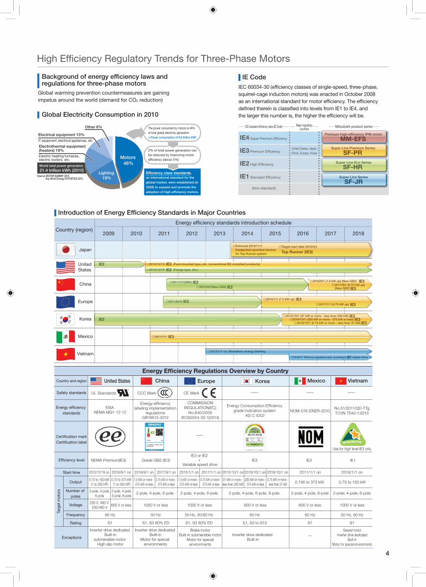
regulations for three-phase motors
Motors 46%
Electrical equipment 10%IT equipment, electrical appliances, etc.
Electrothermal equipment (heaters) 19% Electric heating furnaces, electric boilers, etc.
Other 6%
Lighting 19%
World total power generation
21.4 trillion kWh (2010)Source: MOTOR SUMMIT 2012
Key World Energy STATISTICS 2012
The power consumed by motors is 46% of total global electricity generation. = Power consumption of 9.8 trillion kWh
2% of total power generation can be reduced by improving motor ef�ciency (about 5%)
Efficiency class standards, an international standard for the
global market, were established (in
2008) to expand and promote the
adoption of high-efficiency motors.
Global warming prevention countermeasures are gaining impetus around the world (demand for CO2 reduction)
Global Electricity Consumption in 2010
IEC 60034-30 (ef�ciency classes of single-speed, three-phase, squirrel-cage induction motors) was enacted in October 2008 as an international standard for motor ef�ciency. The ef�ciency de�ned therein is classi�ed into levels from IE1 to IE4, and the larger this number is, the higher the ef�ciency will be.
Super Line Premium Series
SF-PR
Super Line Eco Series
SF-HR
Super Line Series
SF-JR
Premium high-efficiency IPM motor
MM-EFS
(Non-standard)
IE1 Standard Ef�ciency
IE2 High Ef�ciency
IE3 Premium Ef�ciency
IE4 Super Premium Ef�ciency
IEC standard efficiency class (IE Code) Mitsubishi product seriesMajor regulatory countries
United States, Japan, China, Europe, Korea
IE Code
2009 2010 2011 2012 2013 2014 2015 2016 2017 2018
◎Target start date 2015/4/1
Top Runner (IE3)
◎Enforced 2013/11/1
for Top Runner system
Country (region)
Japan
IE2
IE2
standards
Country and region
Safety standards
Start time
Exceptions
Output
Number of poles
Voltage
Rating
Frequency
UL Standards CCC Mark CE Mark
EISA NEMA MG1-12-12
Inverter drive dedicated Built-in
submersible motor High slip motor
Inverter drive dedicated Built-in
—
—
—
— —
Inverter drive dedicated Built-in
Motor for special environments
NEMA Premium(IE3)
2010/12/19 on
0.75 to 150 kW (1 to 200 HP)
230 V, 460 V 230/460 V 600 V or less
60 Hz 60 Hz 60 Hz50 Hz 50 Hz, 50/60 Hz 50 Hz, 60 Hz
1000 V or less 1000 V or less 600 V or less 600 V or less 1000 V or less
0.75 to 373 kW (1 to 500 HP)
7.5 kW or more - 375 kW or less
0.75 kW or more - 375 kW or less
7.5 kW or more - 375 kW or less
37 kW or more - less than 200 kW
200 kW or more - 375 kW or less
0.75 kW or more - less than 37 kW 0.746 to 373 kW 0.75 to 150 kW
0.75 kW or more - 375 kW or less
2016/6/1 on 2016/9/1 on 2017/9/1 on 2015/1/1 on 2017/1/1 on 2015/10/1 on 2016/10/1 on 2018/10/1 on 2011/1/1 on 2016/1/1 on
Use for high level IE3 only
Grade GB2 (IE3)
2-pole, 4-pole, 6-pole 2-pole, 4-pole, 6-pole 2-pole, 4-pole, 6-pole, 8-pole 2-pole, 4-pole, 6-pole2-pole, 4-pole, 6-pole
IE3 IE3 IE1IE3 or IE2
+ Variable speed drive
NOM-016-ENER-2010No.51/2011/QD-TTgTCVN 7540-1:2013
grade indication system KS C 4202
S1 S1, S3 to S10 S1S1, S3 80% ED S1, S3 80% ED S1
COMMISSIONREGULATION(EC)
No.640/2009IEC60034-30-1(2014)
◎2011/1/1 IE3
◎2015/10/1 (37 kW or more - less than 200 kW) IE3◎2016/10/1 (200 kW or more - 375 kW or less) IE3◎2018/10/1 (0.75 kW or more - less than 37 kW) IE3
◎2010/12/19 (Foot-mounted type, etc. conventional IE2 compliant products)IE3◎2010/12/19 (Flange type, etc.)IE2
◎2015/1/1 (7.5 kW up) IE3◎2011/6/16 IE2
◎2017/1/1 (0.75 kW up) IE3
◎2016/9/1 (7.5 kW up) (New GB2) IE3◎2017/9/1 (0.75 kW up)
(New GB2) IE3
◎2011/7/1(GB2) IE2◎2012/9/1(New GB3) IE2
◎2013/1/1 on: Mandatory energy labeling
◎2016/1/1 IE1 original criteria
ChinaUnited States Korea Mexico VietnamEurope
China
Europe
Korea
Mexico
Vietnam
United States
Targ
et m
otor
s
labeling implementation regulations
GB18613-2012
2-pole, 4-pole, 6-pole, 8-pole
2-pole, 4-pole, 6-pole
Brake motor Built-in submersible motor
Motor for special environments
Geared motorInverter drive dedicated
Built-in Motor for special environments
5
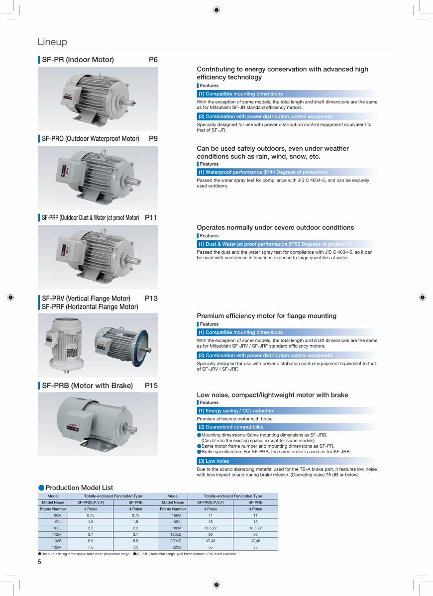
SF-PRB (Motor with Brake) P15
SF-PRO (Outdoor Waterproof Motor) P9
SF-PRP (Outdoor Dust & Water jet proof Motor) P11
SF-PR (Indoor Motor) P6
Features
Features
Features
Features
Can be used safely outdoors, even under weather conditions such as rain, wind, snow, etc.
Operates normally under severe outdoor conditions
Contributing to energy conservation with advanced high
Passed the water spray test for compliance with JIS C 4034-5, and can be securely used outdoors.
Passed the dust and the water spray test for compliance with JIS C 4034-5, so it can
With the exception of some models, the total length and shaft dimensions are the same
Specially designed for use with power distribution control equipment equivalent to that of SF-JRV / SF-JRF.
With the exception of some models, the total length and shaft dimensions are the same
Specially designed for use with power distribution control equipment equivalent to that of SF-JR.
(1) Waterproof performance (IP44 Degrees of protection)
(1) Dust & Water jet proof performance (IP55 Degrees of protection)
(1) Compatible mounting dimensions
(2) Combination with power distribution control equipment
(1) Compatible mounting dimensions
(2) Combination with power distribution control equipment
Features
Low noise, compact/lightweight motor with brake
● Mounting dimensions: Same mounting dimensions as SF-JRB.
●Same motor frame number and mounting dimensions as SF-PR. ●
Due to the sound absorbing material used for the TB-A brake part, it features low noise with less impact sound during brake release. (Operating noise 75 dB or below)
(1) Energy saving / CO2 reduction
(2) Guaranteed compatibility
(3) Low noise
Lineup
●Production Model ListModel Totally-enclosed Fancooled Type
Model Name SF-PR(O,P,V,F) SF-PRB
Frame Number 4 Poles 4 Poles
80M 0.75 0.75
90L 1.5 1.5
100L 2.2 2.2
112M 3.7 3.7
132S 5.5 5.5
132M 7.5 7.5
●The output listing in the above table is the production range. ●SF-PRF (Horizontal �ange type) frame number 225S is not available.
Model Totally-enclosed Fancooled Type
Model Name SF-PR(O,P,V,F) SF-PRB
Frame Number 4 Poles 4 Poles
160M 11 11
160L 15 15
180M 18.5,22 18.5,22
180LD 30 30
200LD 37,45 37,45
225S 55 55
SF-PRV (Vertical Flange Motor) P13SF-PRF (Horizontal Flange Motor)
6●All above graph datas are based on Mitsubishi Electric Japan motors.
Premium Efficiency Motors
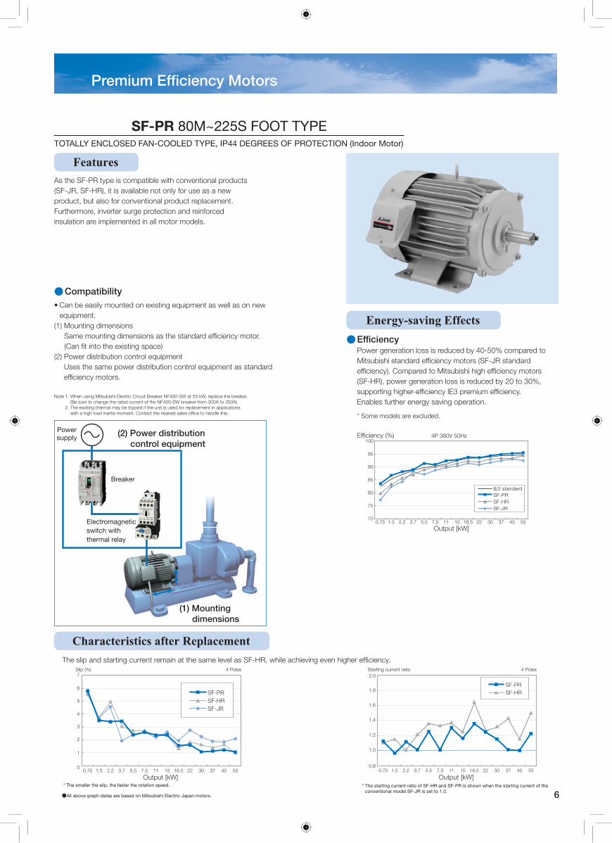
(1) Mounting dimensions
Breaker
Power supply (2) Power distribution
control equipment
Electromagnetic switch with thermal relay
• Can be easily mounted on existing equipment as well as on new equipment.
(1) Mounting dimensions Same mounting dimensions as the standard efficiency motor. (Can fit into the existing space)
tnempiuqe lortnoc noitubirtsid rewoP )2(Uses the same power distribution control equipment as standard efficiency motors.
.rekaerb eht ecalper ,Wk 55 ta WS-004FN rekaerB tiucriC cirtcelE ihsibustiM gnisu nehW .1 etoN(Be sure to change the rated current of the NF400-SW breaker from 300A to 350A)
snoitacilppa ni tnemecalper rof desu si tinu eht fi deppirt eb yam lamreht gnitsixe ehT .2with a high load inertia moment. Contact the nearest sales office to handle this.
●Compatibility
As the SF-PR type is compatible with conventional products (SF-JR, SF-HR), it is available not only for use as a new product, but also for conventional product replacement. Furthermore, inverter surge protection and reinforced insulation are implemented in all motor models.
Features
Characteristics after Replacement ciency.
* The smaller the slip, the faster the rotation speed. eht fo tnerruc gnitrats eht nehw nwohs si RP-FS dna RH-FS fo oitar tnerruc gnitrats ehT *conventional model SF-JR is set to 1.0.
0
1
2
3
4
5
6
7
0.75 5.1 2.2 7.3 5.5 5.7 11 51 5.81 22 03 73 54 55
Output [kW]
Slip (%) 4 Poles
SF-PRSF-HRSF-JR
Output [kW]
Starting current ratio 4 Poles
0.8
1.0
1.2
1.4
1.6
1.8
2.0
0.75 5.1 2.2 7.3 5.5 5.7 11 51 5.81 22 03 73 54 55
SF-PRSF-HR
Energy-saving Effects
* Some models are excluded.
Power generation loss is reduced by 40-50% compared to
(SF-HR), power generation loss is reduced by 20 to 30%,
Enables further energy saving operation.
●
SF-PR 80M~225S FOOT TYPETOTALLY ENCLOSED FAN-COOLED TYPE, IP44 DEGREES OF PROTECTION (Indoor Motor)
0.75
4P 380V 50Hz
70
75
80
85
90
95
100
1.5 2.2 3.7 5.5 7.5 11 15 18.5 22 30 37 45 55Output [kW]
SF-PRSF-HR
IE3 standard
SF-JR
7
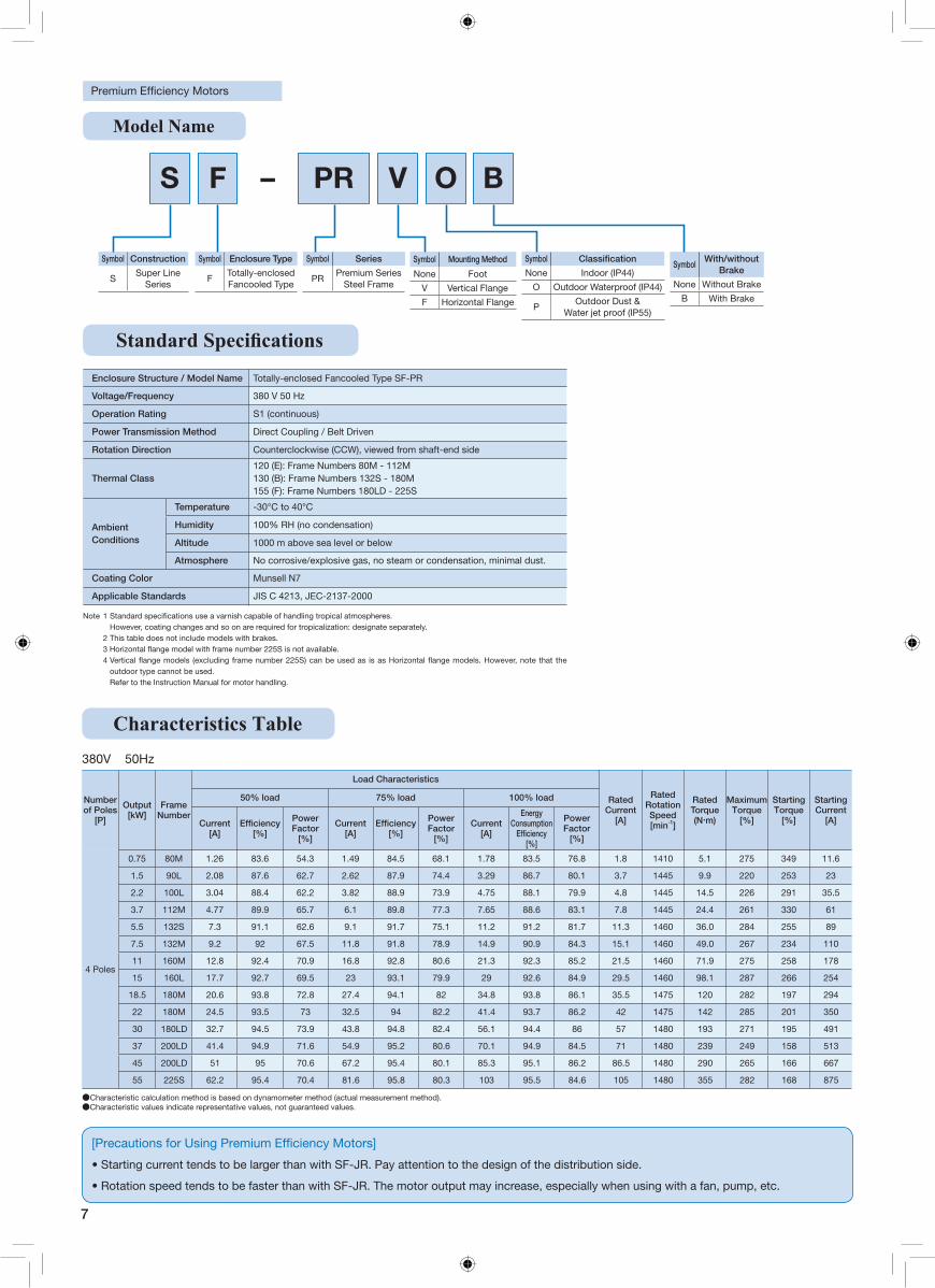
Model Name
Enclosure Structure / Model Name Totally-enclosed Fancooled Type SF-PR
Voltage/Frequency 380 V 50 Hz
Operation Rating S1 (continuous)
Power Transmission Method Direct Coupling / Belt Driven
Rotation Direction Counterclockwise (CCW), viewed from shaft-end side
Thermal Class120 (E): Frame Numbers 80M - 112M 130 (B): Frame Numbers 132S - 180M 155 (F): Frame Numbers 180LD - 225S
Ambient Conditions
Temperature -30°C to 40°C
Humidity 100% RH (no condensation)
Altitude 1000 m above sea level or below
Atmosphere No corrosive/explosive gas, no steam or condensation, minimal dust.
Coating Color Munsell N7
Applicable Standards JIS C 4213, JEC-2137-2000
Note 1 However, coating changes and so on are required for tropicalization: designate separately.
2 This table does not include models with brakes.
4 outdoor type cannot be used.Refer to the Instruction Manual for motor handling.
Symbol Construction
SSuper Line
Series
Symbol Enclosure Type
FTotally-enclosed Fancooled Type
Symbol Classification
None Indoor (IP44)
O Outdoor Waterproof (IP44)
POutdoor Dust &
Water jet proof (IP55)
SymbolWith/without
Brake
None Without Brake
B With Brake
Symbol Mounting Method
None Foot
V Vertical Flange
F Horizontal Flange
Symbol Series
PRPremium Series
Steel Frame
S F V O BPR–
380V 50Hz
Characteristics Table
●Characteristic calculation method is based on dynamometer method (actual measurement method). ●Characteristic values indicate representative values, not guaranteed values.
Number of Poles
[P]
Output [kW]
Frame Number
Load Characteristics
Rated Current
[A]
Rated Rotation Speed [min-1]
Rated Torque (N・m)
Maximum Torque
[%]
Starting Torque
[%]
Starting Current
[A]
50% load 75% load 100% load
Current [A]
[%]
Power Factor
[%]
Current [A]
[%]
Power Factor
[%]
Current [A]
Energy Consumption
[%]
Power Factor
[%]
4 Poles
0.75 80M 1.26 83.6 54.3 1.49 84.5 68.1 1.78 83.5 76.8 1.8 1410 5.1 275 349 11.6
1.5 90L 2.08 87.6 62.7 2.62 87.9 74.4 3.29 86.7 80.1 3.7 1445 9.9 220 253 23
2.2 100L 3.04 88.4 62.2 3.82 88.9 73.9 4.75 88.1 79.9 4.8 1445 14.5 226 291 35.5
3.7 112M 4.77 89.9 65.7 6.1 89.8 77.3 7.65 88.6 83.1 7.8 1445 24.4 261 330 61
5.5 132S 7.3 91.1 62.6 9.1 91.7 75.1 11.2 91.2 81.7 11.3 1460 36.0 284 255 89
7.5 132M 9.2 92 67.5 11.8 91.8 78.9 14.9 90.9 84.3 15.1 1460 49.0 267 234 110
11 160M 12.8 92.4 70.9 16.8 92.8 80.6 21.3 92.3 85.2 21.5 1460 71.9 275 258 178
15 160L 17.7 92.7 69.5 23 93.1 79.9 29 92.6 84.9 29.5 1460 98.1 287 266 254
18.5 180M 20.6 93.8 72.8 27.4 94.1 82 34.8 93.8 86.1 35.5 1475 120 282 197 294
22 180M 24.5 93.5 73 32.5 94 82.2 41.4 93.7 86.2 42 1475 142 285 201 350
30 180LD 32.7 94.5 73.9 43.8 94.8 82.4 56.1 94.4 86 57 1480 193 271 195 491
37 200LD 41.4 94.9 71.6 54.9 95.2 80.6 70.1 94.9 84.5 71 1480 239 249 158 513
45 200LD 51 95 70.6 67.2 95.4 80.1 85.3 95.1 86.2 86.5 1480 290 265 166 667
55 225S 62.2 95.4 70.4 81.6 95.8 80.3 103 95.5 84.6 105 1480 355 282 168 875
• Starting current tends to be larger than with SF-JR. Pay attention to the design of the distribution side.
• Rotation speed tends to be faster than with SF-JR. The motor output may increase, especially when using with a fan, pump, etc.
8
Figure - 1 Figure - 3 Shaft End Dimensions
LR
A BKA
NF F XB
D
KG C
G
ME E
XZ
KD
KL
H
Viewing the mounting feet from above
LR
A BKA
NF F
K
XB
IH
CG
KLD
MLM
E EJ
KG
Z
X
KD
Viewing the mounting feet from above
W
S
U
T
QK*
Q
Figure - 2 Figure - 4
IH
CG
KLD
ME E
J
LR
A BKA
N
F F XB
KG KD
X
Z
Viewing the mounting feet from above
LR
BAKA
F F
N
XBE E
M
J
D
G CH
KP
Viewing the mounting feet from above
X
Z
KD
KG
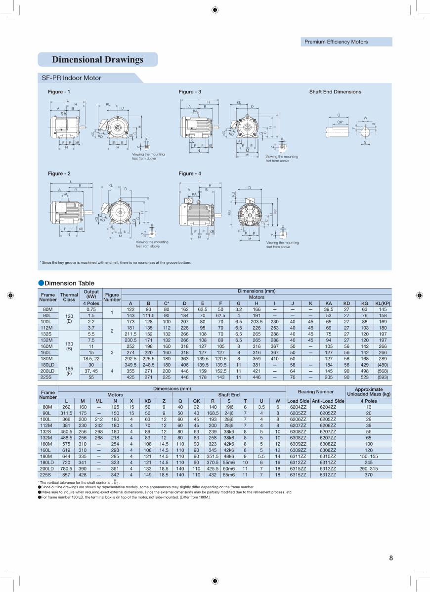
Dimensional Drawings
SF-PR Indoor Motor
●Dimension Table
Frame Number
Thermal Class
Output Figure (kW)
Number
Dimensions (mm) Motors
4 Poles A B C* D E F G H I J K KA KD KG KL(KP)80M
120(E)
0.751
122 93 80 162 62.5 50 3.2 166 — — — 39.5 27 63 14590L 1.5 143 111.5 90 184 70 62.5 4 191 — — — 53 27 76 158
100L 2.2
2
173 128 100 207 80 70 6.5 203.5 230 40 45 65 27 88 169112M 3.7 181 135 112 228 95 70 6.5 226 253 40 45 69 27 103 180132S
130(B)
5.5 211.5 152 132 266 108 70 6.5 265 288 40 45 75 27 120 197132M 7.5 230.5 171 132 266 108 89 6.5 265 288 40 45 94 27 120 197160M 11
3252 198 160 318 127 105 8 316 367 50 — 105 56 142 266
160L 15 274 220 160 318 127 127 8 316 367 50 — 127 56 142 266180M 18.5, 22 292.5 225.5 180 363 139.5 120.5 8 359 410 50 — 127 56 168 289180LD
155(F)
304
349.5 248.5 180 406 139.5 139.5 11 381 — 58 — 184 56 429 (480)200LD 37, 45 355 271 200 446 159 152.5 11 421 — 64 — 145 90 498 (568)225S 55 425 271 225 446 178 143 11 446 — 70 — 205 90 523 (593)
* Since the key groove is machined with end mill, there is no roundness at the groove bottom.
* The vertical tolerance for the shaft center is 0− 0.5 .
●Since outline drawings are shown by representative models, some appearances may slightly differ depending on the frame number. ●Make sure to inquire when requiring exact external dimensions, since the external dimensions may be partially modi�ed due to the re�nement process, etc. ●For frame number 180 LD, the terminal box is on top of the motor, not side-mounted. (Differ from 180M.)
Frame Number
Dimensions (mm) Bearing Number Approximate
Unloaded Mass (kg) Motors Shaft EndL M ML N X XB Z Q QK R S T U W Load Side Anti-Load Side 4 Poles
80M 262 160 — 125 15 50 9 40 32 140 19j6 6 3.5 6 6204ZZ 6204ZZ 1390L 311.5 175 — 150 15 56 9 50 40 168.5 24j6 7 4 8 6205ZZ 6205ZZ 20
100L 366 200 212 180 4 63 12 60 45 193 28j6 7 4 8 6206ZZ 6205ZZ 29112M 381 230 242 180 4 70 12 60 45 200 28j6 7 4 8 6207ZZ 6206ZZ 39132S 450.5 256 268 180 4 89 12 80 63 239 38k6 8 5 10 6308ZZ 6207ZZ 56132M 488.5 256 268 218 4 89 12 80 63 258 38k6 8 5 10 6308ZZ 6207ZZ 65160M 575 310 — 254 4 108 14.5 110 90 323 42k6 8 5 12 6309ZZ 6308ZZ 100160L 619 310 — 298 4 108 14.5 110 90 345 42k6 8 5 12 6309ZZ 6308ZZ 120180M 644 335 — 285 4 121 14.5 110 90 351.5 48k6 9 5.5 14 6311ZZ 6310ZZ 150, 155180LD 720 341 — 323 4 121 14.5 110 90 370.5 55m6 10 6 16 6312ZZ 6311ZZ 245200LD 780.5 390 — 361 4 133 18.5 140 110 425.5 60m6 11 7 18 6315ZZ 6312ZZ 290, 315225S 857 428 — 342 4 149 18.5 140 110 432 65m6 11 7 18 6315ZZ 6312ZZ 370
9
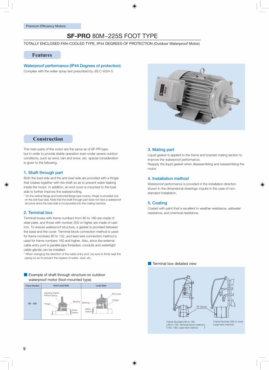
Waterproof performance (IP44 Degrees of protection) Complies with the water spray test prescribed by JIS C 4034-5.
Construction
The main parts of the motor are the same as of SF-PR type, but in order to provide stable operation even under severe outdoor conditions, such as wind, rain and snow, etc. special consideration is given to the following.
1. Shaft through part Both the load side and the anti-load side are provided with a fringer that rotates together with the shaft so as to prevent water leaking inside the motor. In addition, an end cover is mounted to the load
on the anti-load side. Note that the shaft through part does not have a waterproof structure since the load side is incorporated into the mating machine.
2. Terminal boxTerminal boxes with frame numbers from 80 to 180 are made of steel plate, and those with number 200 or higher are made of cast iron. To ensure waterproof structure, a gasket is provided between the base and the cover. Terminal block connection method is used for frame numbers 80 to 132, and lead wire connection method is used for frame numbers 160 and higher. Also, since the external cable entry port is parallel pipe threaded, conduits and watertight cable glands can be installed.
piping so as to prevent the ingress of water, dust, etc.
3. Mating part Liquid gasket is applied to the frame and bracket mating section to improve the waterproof performance. Reapply the liquid gasket when disassembling and reassembling the motor.
4. Installation method Waterproof performance is provided in the installation direction shown in the dimensional drawings; inquire in the case of non-standard installation.
5. Coating Coated with paint that is excellent in weather resistance, saltwater resistance, and chemical resistance.
■ Example of shaft through structure on outdoor waterproof motor (foot-mounted type)
Frame Number
80 - 225
Anti-Load Side Load Side
Fringer Bearing
Adjusting Washer Preload Spring
Motor Interior
Fringer
End cover
Bearing
Motor Interior
■ Terminal box detailed view
Frame Numbers 80 to 180 80 to 132: Terminal block method 160, 180: Lead wire method
Frame Number 200 or more (Lead wire method)( )
PF Screw
Features
SF-PRO 80M~225S FOOT TYPETOTALLY ENCLOSED FAN-COOLED TYPE, IP44 DEGREES OF PROTECTION (Outdoor Waterproof Motor)
10
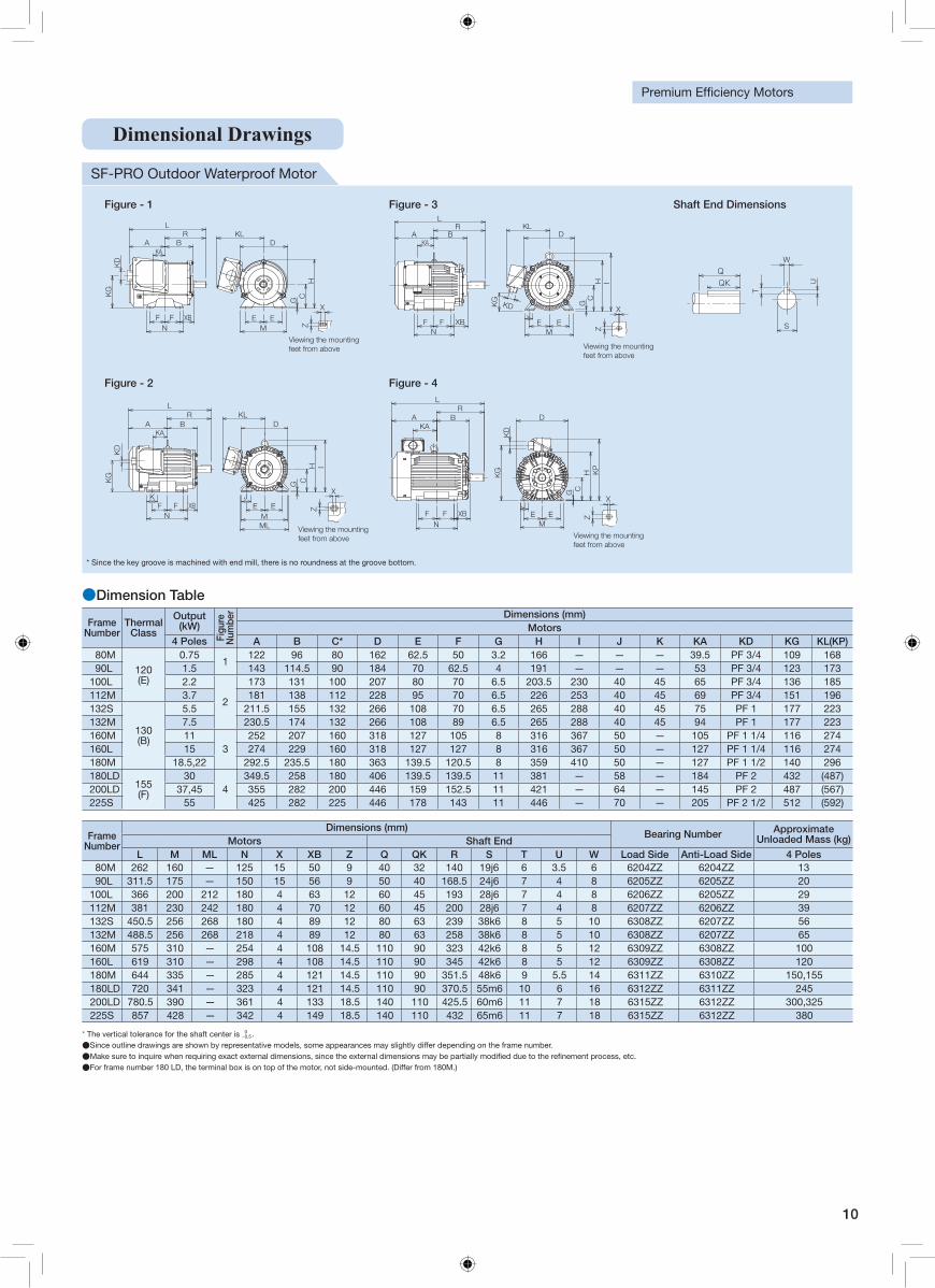
SF-PRO Outdoor Waterproof Motor
●Dimension Table
Frame Number
Thermal Class
Output (kW)
Figu
re
Num
ber Dimensions (mm)
Motors4 Poles A B C* D E F G H I J K KA KD KG KL(KP)
80M
120(E)
0.751
122 96 80 162 62.5 50 3.2 166 — — — 39.5 PF 3/4 109 16890L 1.5 143 114.5 90 184 70 62.5 4 191 — — — 53 PF 3/4 123 173
100L 2.2
2
173 131 100 207 80 70 6.5 203.5 230 40 45 65 PF 3/4 136 185112M 3.7 181 138 112 228 95 70 6.5 226 253 40 45 69 PF 3/4 151 196132S
130(B)
5.5 211.5 155 132 266 108 70 6.5 265 288 40 45 75 PF 1 177 223132M 7.5 230.5 174 132 266 108 89 6.5 265 288 40 45 94 PF 1 177 223160M 11
3252 207 160 318 127 105 8 316 367 50 — 105 PF 1 1/4 116 274
160L 15 274 229 160 318 127 127 8 316 367 50 — 127 PF 1 1/4 116 274180M 18.5,22 292.5 235.5 180 363 139.5 120.5 8 359 410 50 — 127 PF 1 1/2 140 296180LD
155(F)
304
349.5 258 180 406 139.5 139.5 11 381 — 58 — 184 PF 2 432 (487)200LD 37,45 355 282 200 446 159 152.5 11 421 — 64 — 145 PF 2 487 (567)225S 55 425 282 225 446 178 143 11 446 — 70 — 205 PF 2 1/2 512 (592)
Frame Number
Dimensions (mm) Bearing Number Approximate
Unloaded Mass (kg) Motors Shaft EndL M ML N X XB Z Q QK R S T U W Load Side Anti-Load Side 4 Poles
80M 262 160 — 125 15 50 9 40 32 140 19j6 6 3.5 6 6204ZZ 6204ZZ 1390L 311.5 175 — 150 15 56 9 50 40 168.5 24j6 7 4 8 6205ZZ 6205ZZ 20
100L 366 200 212 180 4 63 12 60 45 193 28j6 7 4 8 6206ZZ 6205ZZ 29112M 381 230 242 180 4 70 12 60 45 200 28j6 7 4 8 6207ZZ 6206ZZ 39132S 450.5 256 268 180 4 89 12 80 63 239 38k6 8 5 10 6308ZZ 6207ZZ 56132M 488.5 256 268 218 4 89 12 80 63 258 38k6 8 5 10 6308ZZ 6207ZZ 65160M 575 310 — 254 4 108 14.5 110 90 323 42k6 8 5 12 6309ZZ 6308ZZ 100160L 619 310 — 298 4 108 14.5 110 90 345 42k6 8 5 12 6309ZZ 6308ZZ 120180M 644 335 — 285 4 121 14.5 110 90 351.5 48k6 9 5.5 14 6311ZZ 6310ZZ 150,155180LD 720 341 — 323 4 121 14.5 110 90 370.5 55m6 10 6 16 6312ZZ 6311ZZ 245200LD 780.5 390 — 361 4 133 18.5 140 110 425.5 60m6 11 7 18 6315ZZ 6312ZZ 300,325225S 857 428 — 342 4 149 18.5 140 110 432 65m6 11 7 18 6315ZZ 6312ZZ 380
* The vertical tolerance for the shaft center is 0−0.5.
●Since outline drawings are shown by representative models, some appearances may slightly differ depending on the frame number. ●Make sure to inquire when requiring exact external dimensions, since the external dimensions may be partially modi�ed due to the re�nement process, etc. ●For frame number 180 LD, the terminal box is on top of the motor, not side-mounted. (Differ from 180M.)
Figure - 1 Figure - 3 Shaft End Dimensions
LR
A BKA
NF F XB
KG
KD
D
CG
ME E
KL
HX
Z
Viewing the mounting feet from above
IHC
G
KLD
ME E
J
LR
A BKA
NF F XB
KG
KD X
Z
Viewing the mounting feet from above
W
S
U
T
QK
Q
Figure - 2 Figure - 4
LR
A BKA
NF F
KXB
IHCG
KLD
MLM
E EJ
KD
KG
Z
X
Viewing the mounting feet from above
LR
BAKA
F FN
XB E EM
J
D
G CH K
P
KG
KD
X
Z
Viewing the mounting feet from above
W
S
U
T
QKQ
取付足を上側より見て
X
Z
LR
A BKA
NF F
KG
KD
D
CG
ME E
KL
H
LR
A BKA
NF F
KXB
IHCG
KLD
MLM
E EJ
取付足を上側より見て
Z
X
KD
KG
取付足を上側より見て
IH
CG
KLD
ME E
J
LR
A BKA
NF F XB
X
ZKG
KD
LRBA
KA
F FN
XB E EM
J
D
G CH KP
取付足を上側より見て
X
Z
KG
KD
軸端寸法図
XB
* Since the key groove is machined with end mill, there is no roundness at the groove bottom.
Dimensional Drawings
11
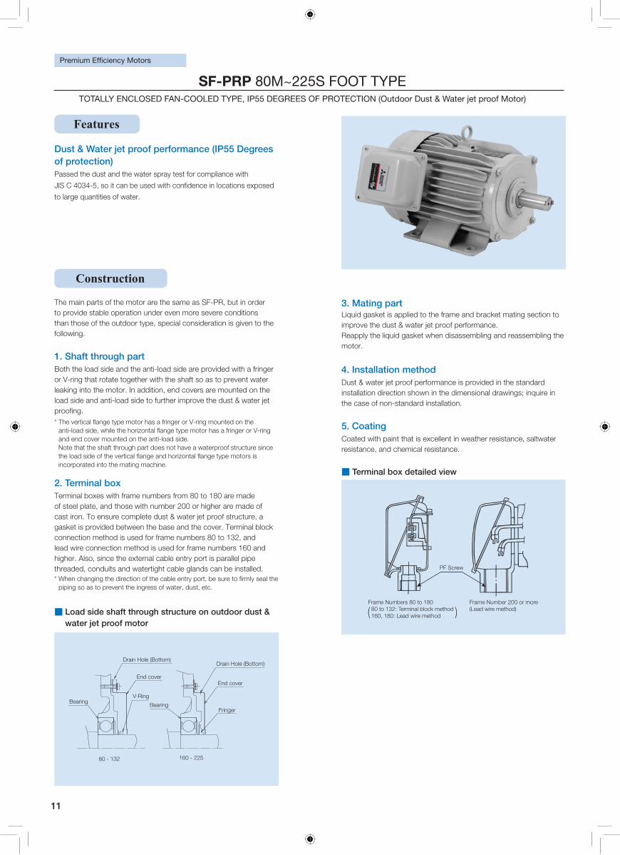
Dust & Water jet proof performance (IP55 Degrees of protection)Passed the dust and the water spray test for compliance with
to large quantities of water.
The main parts of the motor are the same as SF-PR, but in order to provide stable operation under even more severe conditions than those of the outdoor type, special consideration is given to the following.
1. Shaft through part Both the load side and the anti-load side are provided with a fringer or V-ring that rotate together with the shaft so as to prevent water leaking into the motor. In addition, end covers are mounted on the load side and anti-load side to further improve the dust & water jet
anti-and end cover mounted on the anti-load side. Note that the shaft through part does not have a waterproof structure since
incorporated into the mating machine.
2. Terminal box Terminal boxes with frame numbers from 80 to 180 are made of steel plate, and those with number 200 or higher are made of cast iron. To ensure complete dust & water jet proof structure, a gasket is provided between the base and the cover. Terminal block connection method is used for frame numbers 80 to 132, and lead wire connection method is used for frame numbers 160 and higher. Also, since the external cable entry port is parallel pipe threaded, conduits and watertight cable glands can be installed.
piping so as to prevent the ingress of water, dust, etc.
3. Mating part Liquid gasket is applied to the frame and bracket mating section to improve the dust & water jet proof performance. Reapply the liquid gasket when disassembling and reassembling the motor.
4. Installation method Dust & water jet proof performance is provided in the standard installation direction shown in the dimensional drawings; inquire in the case of non-standard installation.
5. Coating Coated with paint that is excellent in weather resistance, saltwater resistance, and chemical resistance.
■ Load side shaft through structure on outdoor dust & water jet proof motor
■ Terminal box detailed view
Frame Numbers 80 to 180 80 to 132: Terminal block method 160, 180: Lead wire method
Frame Number 200 or more (Lead wire method)( )
PF Screw
80 - 132 160 - 225
End cover
V-Ring
Fringer
End cover
Bearing
Drain Hole (Bottom)
Bearing
Drain Hole (Bottom)
Features
Construction
SF-PRP 80M~225S FOOT TYPE TOTALLY ENCLOSED FAN-COOLED TYPE, IP55 DEGREES OF PROTECTION (Outdoor Dust & Water jet proof Motor)
12
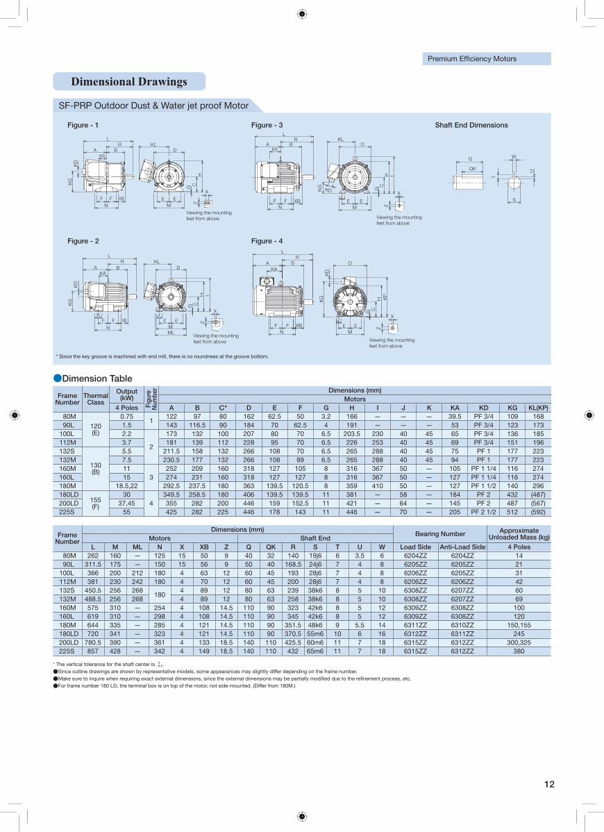
SF-PRP Outdoor Dust & Water jet proof Motor
Frame Number
Thermal Class
Output (kW)
Figu
re
Num
ber Dimensions (mm)
Motors4 Poles A B C* D E F G H I J K KA KD KG KL(KP)
80M
120 (E)
0.751
122 97 80 162 62.5 50 3.2 166 — — — 39.5 PF 3/4 109 16890L 1.5 143 116.5 90 184 70 62.5 4 191 — — — 53 PF 3/4 123 173
100L 2.2
2
173 132 100 207 80 70 6.5 203.5 230 40 45 65 PF 3/4 136 185112M 3.7 181 139 112 228 95 70 6.5 226 253 40 45 69 PF 3/4 151 196132S
130 (B)
5.5 211.5 158 132 266 108 70 6.5 265 288 40 45 75 PF 1 177 223132M 7.5 230.5 177 132 266 108 89 6.5 265 288 40 45 94 PF 1 177 223160M 11
3252 209 160 318 127 105 8 316 367 50 — 105 PF 1 1/4 116 274
160L 15 274 231 160 318 127 127 8 316 367 50 — 127 PF 1 1/4 116 274180M 18.5,22 292.5 237.5 180 363 139.5 120.5 8 359 410 50 — 127 PF 1 1/2 140 296180LD
155 (F)
304
349.5 258.5 180 406 139.5 139.5 11 381 — 58 — 184 PF 2 432 (487)200LD 37,45 355 282 200 446 159 152.5 11 421 — 64 — 145 PF 2 487 (567)225S 55 425 282 225 446 178 143 11 446 — 70 — 205 PF 2 1/2 512 (592)
Frame Number
Dimensions (mm) Bearing Number Approximate
Unloaded Mass (kg) Motors Shaft EndL M ML N X XB Z Q QK R S T U W Load Side Anti-Load Side 4 Poles
80M 262 160 — 125 15 50 9 40 32 140 19j6 6 3.5 6 6204ZZ 6204ZZ 1490L 311.5 175 — 150 15 56 9 50 40 168.5 24j6 7 4 8 6205ZZ 6205ZZ 21
100L 366 200 212 180 4 63 12 60 45 193 28j6 7 4 8 6206ZZ 6205ZZ 31112M 381 230 242 180 4 70 12 60 45 200 28j6 7 4 8 6206ZZ 6206ZZ 42132S 450.5 256 268
1804 89 12 80 63 239 38k6 8 5 10 6308ZZ 6207ZZ 60
132M 488.5 256 268 4 89 12 80 63 258 38k6 8 5 10 6308ZZ 6207ZZ 69160M 575 310 — 254 4 108 14.5 110 90 323 42k6 8 5 12 6309ZZ 6308ZZ 100160L 619 310 — 298 4 108 14.5 110 90 345 42k6 8 5 12 6309ZZ 6308ZZ 120180M 644 335 — 285 4 121 14.5 110 90 351.5 48k6 9 5.5 14 6311ZZ 6310ZZ 150,155180LD 720 341 — 323 4 121 14.5 110 90 370.5 55m6 10 6 16 6312ZZ 6311ZZ 245200LD 780.5 390 — 361 4 133 18.5 140 110 425.5 60m6 11 7 18 6315ZZ 6312ZZ 300,325225S 857 428 — 342 4 149 18.5 140 110 432 65m6 11 7 18 6315ZZ 6312ZZ 380
●Dimension Table
* The vertical tolerance for the shaft center is 0−0.5.
●Since outline drawings are shown by representative models, some appearances may slightly differ depending on the frame number. ●Make sure to inquire when requiring exact external dimensions, since the external dimensions may be partially modi�ed due to the re�nement process, etc. ●For frame number 180 LD, the terminal box is on top of the motor, not side-mounted. (Differ from 180M.)
Figure - 1 Figure - 3 Shaft End Dimensions
XZ
LR
A BKA
NF F XB
KG
KD
D
CG
ME E
KL
H
Viewing the mounting feet from above
IHC
G
KLD
ME E
J
LR
A BKA
NF F XB
X
Z
KG KD
Viewing the mounting feet from above
W
S
U
T
QK
Q
Figure - 2 Figure - 4
LR
A BKA
N
F FK
XB
IHCG
KLD
MLM
E EJ
Z
X
KD
KG
Viewing the mounting feet from above
LR
BAKA
F FN
XB E EM
J
D
G CH K
P
X
Z
KG
KD
Viewing the mounting feet from above
* Since the key groove is machined with end mill, there is no roundness at the groove bottom.
Dimensional Drawings
13
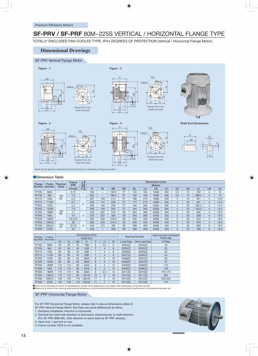
Dimensional Drawings
●Dimension Table
FlangeNumber
Frame Number
Thermal Class
Output (kW)
Fig
ure
Num
ber Dimensions (mm)
Motors4 Poles D IE KB KD KL LA LB LC LE LG LL LN LZ
FF165 80M
120(E)
0.751
166 — 139.5 27 145 165 130j6 200 3.5 12 222 4 12FF165 90L 1.5 202 — 198.5 27 158 165 130j6 200 3.5 12 288.5 4 12FF215 100L 2.2
2
207 130 213 27 166 215 180j6 250 4 16 321 4 14.5FF215 112M 3.7 228 141 239 27 177 215 180j6 250 4 16 351 4 14.5FF265 132S
130(B)
5.5 266 156 256 27 194 265 230j6 300 4 20 392.5 4 14.5FF265 132M 7.5 266 156 294 27 194 265 230j6 300 4 20 430.5 4 14.5FF300 160M 11
3318 207 318 56 264 300 250j6 350 5 20 465 4 18.5
FF300 160L 15 318 207 362 56 264 300 250j6 350 5 20 509 4 18.5FF350 180M 18.5,22 363 230 378.5 56 285 350 300j6 400 5 20 544 4 18.5FF350 180LD
155(F)
304
406 255 510.5 56 300 350 300j6 400 5 20 676 4 18.5FF400 200LD 37,45 446 275 485 90 368 400 350j6 450 5 22 695 8 18.5FF500 225S 55 446 — 560 90 368 500 450j6 550 5 22 780 8 18.5
FlangeNumber
Frame Number
Dimensions (mm)Bearing Number Approximate Unloaded
Mass (kg) Shaft EndLR Q QK S T U W Load Side Anti-Load Side 4 Poles
FF165 80M 40 40 32 19j6 6 3.5 6 6204ZZ 6204ZZ 16FF165 90L 50 50 40 24j6 7 4 8 6205ZZ 6205ZZ 23FF215 100L 60 60 45 28j6 7 4 8 6206ZZ 6205ZZ 33FF215 112M 60 60 45 28j6 7 4 8 6207ZZ 6206ZZ 44FF265 132S 80 80 63 38k6 8 5 10 6308ZZ 6207ZZ 63FF265 132M 80 80 63 38k6 8 5 10 6308ZZ 6207ZZ 72FF300 160M 110 110 90 42k6 8 5 12 6309ZZ 6308ZZ 110FF300 160L 110 110 90 42k6 8 5 12 6309ZZ 6308ZZ 130FF350 180M 110 110 90 48k6 9 5.5 14 6311ZZ 6310ZZ 170,175FF350 180LD 110 110 90 55m6 10 6 16 6312ZZ 6311ZZ 265FF400 200LD 140 140 110 60m6 11 7 18 6315ZZ 6312ZZ 320,345FF500 225S 140 140 110 65m6 11 7 18 6315ZZ 6312ZZ 415
●Since outline drawings are shown by representative models, some appearances may slightly differ depending on the frame number. ●Make sure to inquire when requiring exact external dimensions, since the external dimensions may be partially modi�ed due to the re�nement process, etc.
SF-PRV Vertical Flange Motor
SF-PRF Horizontal Flange Motor
Figure - 1 Figure - 3
LNxLZ
Viewed from the shaft end side
ALA
A
KL
KD
LCLB
LLLR
KB
ØD
SectionAA
LELG
LNxLZ
KD
SectionAA
Viewed from the shaft end side
D
LCLB
LLLR
KB
LELG
IE IE
LA A
A
KL
Figure - 2 Figure - 4 Shaft End Dimensions
LNxLZ
KD
KL
Viewed from the shaft end side
SectionAA
LCLB
ØD
LLK
BLRLE
LG
IE IE
LA A
A
LNxLZ
KD
SectionAA
LCLB
LLLRLE
LG
D
A
Viewed from the shaft end side
LA
IEIE
KB A
KL W
S
U
T
QK
Q
* Since the key groove is machined with end mill, there is no roundness at the groove bottom.
SF-PRV / SF-PRF 80M~225S VERTICAL / HORIZONTAL FLANGE TYPETOTALLY ENCLOSED FAN-COOLED TYPE, IP44 DEGREES OF PROTECTION (Vertical / Horizontal Flange Motor)
For SF-PRF Horizontal Flange Motor, please refer to above dimensions detail ofSF-PRV Vertical Flange Motor. But there are some differences as follow.1. Standard installation direction is Horizontal.2. Terminal box lead hole direction is downward, perpendicular to shaft direction. (For SF-PRV 80M-90L, their direction is same style as SF-PRF already.) 3. Have only 1 eye bolt on top. 4. Frame number 225S is not available.
14
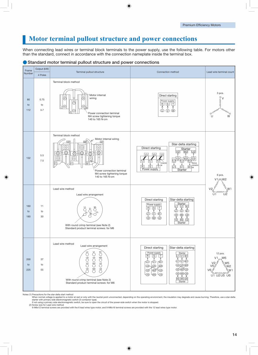
Motor terminal pullout structure and power connectionsWhen connecting lead wires or terminal block terminals to the power supply, use the following table. For motors other than the standard, connect in accordance with the connection nameplate inside the terminal box.
●Standard motor terminal pullout structure and power connections
Frame Number
Output (kW)Terminal pullout structure Connection method Lead wire terminal count
4 Poles
80
to
112
0.75
to
3.7W
V
U
Motor internal wiring
Power connection terminal M4 screw tightening torque 140 to 165 N·cm
Direct starting
Power supply
R S T
U V W
3 pcs.
V
U W
1325.5
7.5
V2 W2 U2
W1V1U1
Motor internal wiring
Power connection terminal M4 screw tightening torque 140 to 165 N·cm
Power supply
Connection barR S T
Direct starting
V2 W2 U2
W1V1U1
StarterV2 W2 U2
U1V2
V1W2
W1U2
U1 V1 W1Starter
Remove connection bar
Star-delta starting
6 pcs.
V1
U1
W1
W2
U2
V2
160
to
180
11
to
30
U1 V1
V2 U2W2
W1
With round crimp terminal (see Note 2) Standard product terminal screws: for M6
Lead wire arrangement
Direct starting Star-delta starting
Power supplyR S T
U1 V1 W1
V2 W2 U2
Starter
Starter
U1 V1 W1
U1 V1 W1
V2 W2 U2
U2W2V2
200
to
225
37
to
55
Lead wire arrangement
U1 V1 W1
U5 V5 W5
V2 W2 U2
V6 W6 U6
With round crimp terminal (see Note 2) Standard product terminal screws: for M6
Direct starting Star-delta starting
Power supplyR S T
U1 V1 W1
U5 V5 W5
V2 W2 U2
V6 W6 U6
StarterU1 V1 W1
U1 V1 W1
U5 V5 W5
V2 W2 U2
V6 W6 U6
V6 W6 U6Starter
12 pcs.
V1
U1
W1
W5W2
W6
U2U5 U6
V2V5
V6
Notes (1) Precautions for the star-delta start method When normal voltage is applied to a motor at rest or only with the neutral point unconnected, depending on the operating environment, the insulation may degrade and cause burning. Therefore, use a star-delta starter with primary side electromagnetic switch (3-contactor type). If not using a primary side electromagnetic switch, be sure to open the circuit of the power-side switch when the motor is stopped.
(2) Screw size for Lead wire method 6-M6x12 terminal screws are provided with the 6 lead wires type motor, and 9-M6x16 terminal screws are provided with the 12 lead wires type motor.
Terminal block method
Terminal block method
Lead wire method
Lead wire method
15
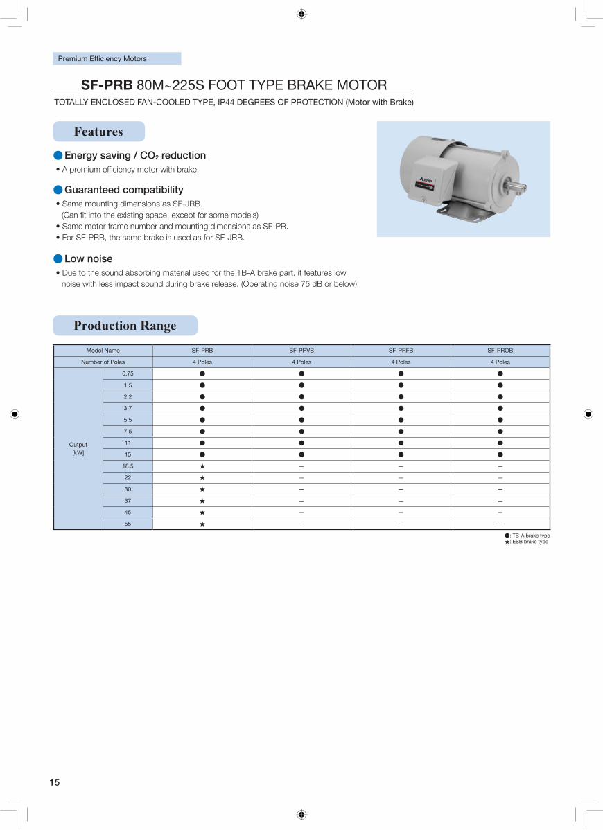
●: TB-A brake type ★: ESB brake type
●Energy saving / CO2 reduction
●Guaranteed compatibility• Same mounting dimensions as SF-JRB.
• Same motor frame number and mounting dimensions as SF-PR. • For SF-PRB, the same brake is used as for SF-JRB.
●Low noise• Due to the sound absorbing material used for the TB-A brake part, it features low
noise with less impact sound during brake release. (Operating noise 75 dB or below)
Model Name SF-PRB SF-PRVB SF-PRFB SF-PROB
Number of Poles 4 Poles 4 Poles 4 Poles 4 Poles
Output [kW]
0.75 ● ● ● ●
1.5 ● ● ● ●
2.2 ● ● ● ●
3.7 ● ● ● ●
5.5 ● ● ● ●
7.5 ● ● ● ●
11 ● ● ● ●
15 ● ● ● ●
18.5 ★ — — —
22 ★ — — —
30 ★ — — —
37 ★ — — —
45 ★ — — —
55 ★ — — —
Production Range
Features
SF-PRB 80M~225S FOOT TYPE BRAKE MOTORTOTALLY ENCLOSED FAN-COOLED TYPE, IP44 DEGREES OF PROTECTION (Motor with Brake)
16
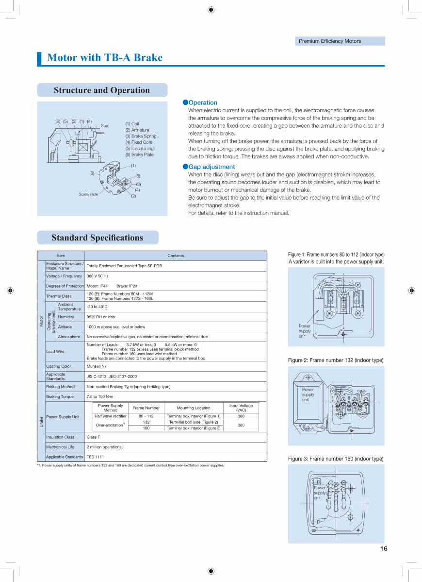
Motor with TB-A Brake
●Operation When electric current is supplied to the coil, the electromagnetic force causes the armature to overcome the compressive force of the braking spring and be
releasing the brake. When turning off the brake power, the armature is pressed back by the force of the braking spring, pressing the disc against the brake plate, and applying braking due to friction torque. The brakes are always applied when non-conductive.
●Gap adjustmentWhen the disc (lining) wears out and the gap (electromagnet stroke) increases, the operating sound becomes louder and suction is disabled, which may lead to motor burnout or mechanical damage of the brake. Be sure to adjust the gap to the initial value before reaching the limit value of the electromagnet stroke. For details, refer to the instruction manual.
Screw Hole
Gap (1) Coil (2) Armature (3) Brake Spring (4) Fixed Core (5) Disc (Lining) (6) Brake Plate
(6) (5) (4)
(3)
(2) (1)
(6)(5)
(4)(2)
(1)
Structure and Operation
*1. Power supply units of frame numbers 132 and 160 are dedicated current control type over-excitation power supplies.
Item Contents
Mot
or
Enclosure Structure / Model Name Totally Enclosed Fan-cooled Type SF-PRB
Voltage / Frequency 380 V 50 Hz
Degrees of Protection Motor: IP44 Brake: IP20
Thermal Class 120 (E): Frame Numbers 80M - 112M 130 (B): Frame Numbers 132S - 160L
Op
erat
ing
Env
ironm
ent
Ambient Temperature -20 to 40°C
Humidity 95% RH or less
Altitude 1000 m above sea level or below
Atmosphere No corrosive/explosive gas, no steam or condensation, minimal dust
Lead Wire
Number of Leads 3.7 kW or less: 3 5.5 kW or more: 6 Frame number 132 or less uses terminal block method Frame number 160 uses lead wire method
Brake leads are connected to the power supply in the terminal box
Coating Color Munsell N7
Applicable Standards JIS C 4213, JEC-2137-2000
Bra
ke
Braking Method Non-excited Braking Type (spring braking type)
Braking Torque 7.5 to 150 N∙m
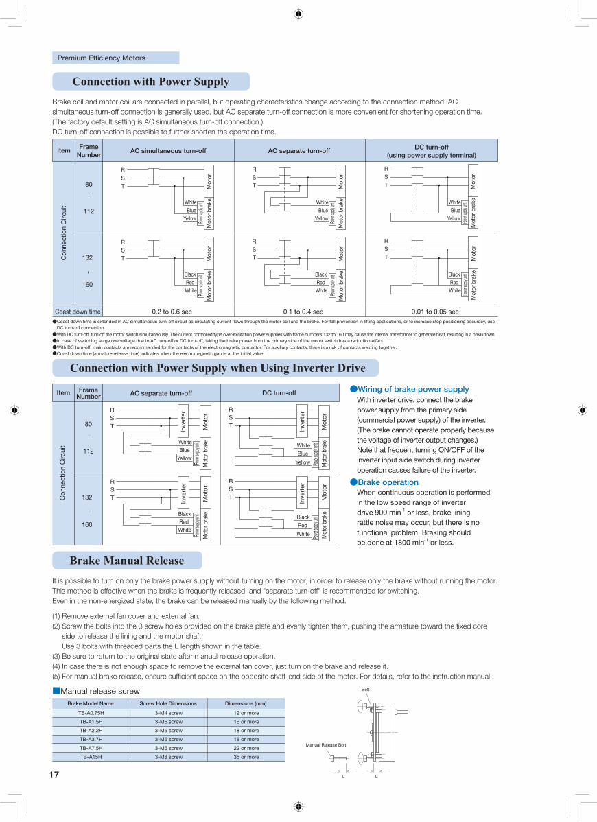
Power Supply Unit
Power Supply Method Frame Number Mounting Location Input Voltage
(VAC)
80 - 112 Terminal box interior (Figure 1) 380
Over-excitation*1 132 Terminal box side (Figure 2)
380160 Terminal box interior (Figure 3)
Insulation Class Class F
Mechanical Life 2 million operations
Applicable Standards TES 1111
Figure 1: Frame numbers 80 to 112 (indoor type)
Figure 2: Frame number 132 (indoor type)
Figure 3: Frame number 160 (indoor type)
A varistor is built into the power supply unit.
U
V
W
Power supply unit
U1 V1 W1
V2 W2 U2
Power supply unit
Power supply unit
17
Connection with Power Supply
Connection with Power Supply when Using Inverter Drive
Brake Manual ReleaseIt is possible to turn on only the brake power supply without turning on the motor, in order to release only the brake without running the motor. This method is effective when the brake is frequently released, and "separate turn-off" is recommended for switching. Even in the non-energized state, the brake can be released manually by the following method.
(1) Remove external fan cover and external fan. (2)
side to release the lining and the motor shaft. Use 3 bolts with threaded parts the L length shown in the table.
(3) Be sure to return to the original state after manual release operation. (4) In case there is not enough space to remove the external fan cover, just turn on the brake and release it.
Brake Model Name Screw Hole Dimensions Dimensions (mm)
TB-A0.75H 3-M4 screw 12 or more
TB-A1.5H 3-M6 screw 16 or more
TB-A2.2H 3-M6 screw 18 or more
TB-A3.7H 3-M6 screw 18 or more
TB-A7.5H 3-M6 screw 22 or more
TB-A15H 3-M8 screw 35 or more
■Manual release screw
L L
Manual Release Bolt
Bolt
●Wiring of brake power supply With inverter drive, connect the brake power supply from the primary side (commercial power supply) of the inverter. (The brake cannot operate properly because the voltage of inverter output changes.) Note that frequent turning ON/OFF of the inverter input side switch during inverter operation causes failure of the inverter.
●Brake operationWhen continuous operation is performed in the low speed range of inverter drive 900 min-1 or less, brake lining rattle noise may occur, but there is no functional problem. Braking should be done at 1800 min-1 or less.
--
Item Frame Number
80
112
132
160
RST
WhiteBlue
Yellow
BlackRed White
WhiteBlue
Yellow
BlackRed
White
RST
RST
RST
DC turn-offAC separate turn-off
Con
nect
ion
Circ
uit
Inve
rter
Mot
or
Mot
or b
rake
Power s
upply u
nit
Mot
or
Mot
or b
rake
Power s
upply u
nit M
otor
M
otor
bra
kePow
er supp
ly unit
Mot
or
Mot
or b
rake
Power s
upply u
nit
Inve
rter
Inve
rter
Inve
rter
Brake coil and motor coil are connected in parallel, but operating characteristics change according to the connection method. AC simultaneous turn-off connection is generally used, but AC separate turn-off connection is more convenient for shortening operation time. (The factory default setting is AC simultaneous turn-off connection.) DC turn-off connection is possible to further shorten the operation time.
- -
Item Frame Number
AC separate turn-off DC turn-off (using power supply terminal)
Coast down time 0.2 to 0.6 sec 0.1 to 0.4 sec 0.01 to 0.05 sec
RST
WhiteBlue
Yellow
WhiteBlue
Yellow
WhiteBlue
Yellow
RST
RST
RST
Black Red White
Black Red White
Black Red White
RST
RST
80
112
132
160
AC simultaneous turn-off
Con
nect
ion
Circ
uit
Power s
upply u
nit
Mot
or
Mot
or b
rake
Power s
upply u
nit
Mot
or
Mot
or b
rake
Power s
upply u
nit
Mot
or
Mot
or b
rake
Power s
upply u
nit
Mot
or
Mot
or b
rake
Power s
upply u
nit
Mot
or
Mot
or b
rake
Power s
upply u
nit
Mot
or
Mot
or b
rake
● Coast down time is extended in AC simultaneous turn-off circuit as circulating current �ows through the motor coil and the brake. For fall prevention in lifting applications, or to increase stop positioning accuracy, use DC turn-off connection. ● With DC turn-off, turn off the motor switch simultaneously. The current controlled type over-excitation power supplies with frame numbers 132 to 160 may cause the internal transformer to generate heat, resulting in a breakdown. ● In case of switching surge overvoltage due to AC turn-off or DC turn-off, taking the brake power from the primary side of the motor switch has a reduction effect. ●With DC turn-off, main contacts are recommended for the contacts of the electromagnetic contactor. For auxiliary contacts, there is a risk of contacts welding together. ●Coast down time (armature release time) indicates when the electromagnetic gap is at the initial value.
18
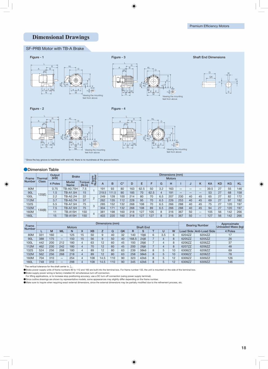
SF-PRB Motor with TB-A Brake
Frame Number
Thermal Class
Output (kW) Brake
Fig
ure
Num
ber Dimensions (mm)
Motors
4 Poles Model Name
Torque (N∙m) A B C* D E F G H I J K KA KD KG KL
80M
120(E)
0.75 TB-A0.75H 7.51
191 93 80 163 62.5 50 3.2 163 — — — 39.5 27 55 14690L 1.5 TB-A1.5H 15 219.5 111.5 90 185 70 62.5 4 191 — — — 53 27 68 158
100L 2.2 TB-A2.2H 222
249 128 100 214 80 70 6.5 207 230 40 45 65 27 82 172112M 3.7 TB-A3.7H 37 262 135 112 228 95 70 6.5 226 253 40 45 69 27 97 182132S
130(B)
5.5 TB-A7.5H 753
285 152 132 268 108 70 6.5 266 288 40 45 75 27 120 197132M 7.5 TB-A7.5H 75 304 171 132 268 108 89 6.5 266 288 40 45 94 27 120 197160M 11 TB-A15H 150
4381 198 160 318 127 105 8 316 367 50 — 105 56 142 266
160L 15 TB-A15H 150 403 220 160 318 127 127 8 316 367 50 — 127 56 142 266
Frame Number
Dimensions (mm) Bearing Number Approximate
Unloaded Mass (kg) Motors Shaft EndL M ML N X XB Z Q QK R S T U W Load Side Anti-Load Side 4 Poles
80M 331 160 — 125 15 50 9 40 32 140 19j6 6 3.5 6 6204ZZ 6204ZZ 1790L 388 175 — 150 15 56 9 50 40 168.5 24j6 7 4 8 6205ZZ 6205ZZ 26
100L 442 200 212 180 4 63 12 60 45 193 28j6 7 4 8 6206ZZ 6206ZZ 37112M 462 230 242 180 4 70 12 60 45 200 28j6 7 4 8 6207ZZ 6206ZZ 48132S 524 256 268 180 4 89 12 80 63 239 38k6 8 5 10 6308ZZ 6208ZZ 69132M 562 256 268 218 4 89 12 80 63 258 38k6 8 5 10 6308ZZ 6208ZZ 78160M 704 310 — 254 4 108 14.5 110 90 323 42k6 8 5 12 6309ZZ 6309ZZ 126160L 748 310 — 298 4 108 14.5 110 90 345 42k6 8 5 12 6309ZZ 6309ZZ 146
●Dimension Table
* The vertical tolerance for the shaft center is 0−0.5 .
●Brake power supply units of frame numbers 80 to 112 and 160 are built into the terminal box. For frame number 132, the unit is mounted on the side of the terminal box. ●Brake supply power wiring is factory installed AC simultaneous turn-off connection. For lifting applications, or to increase stop positioning accuracy, use a DC turn-off connection (using power supply terminal). ●Since outline drawings are shown by representative models, some appearances may slightly differ depending on the frame number. ●Make sure to inquire when requiring exact external dimensions, since the external dimensions may be partially modi�ed due to the re�nement process, etc.
Figure - 1 Figure - 3 Shaft End Dimensions
RA B
KA
NF F XB
KLD
H
G
ME E
XZ
L
KG
KDC
Viewing the mounting feet from above
KG KD
X
Z
KA
LR
A B KLD
KF F XBN
JE E
M
G CH I
Viewing the mounting feet from above
W
S
U
T
QK
Q
Figure - 2 Figure - 4
DKL
KG
Z
X
KA
L
A BR
NF F
KXB
MLM
E EJ
IHCGKD
Viewing the mounting feet from above
X
Z
KA
KDKG
IHCG
KLD
ME E
J
LR
A B
NF F XB
Viewing the mounting feet from above
軸端寸法図
W
S
U
T
QK
Q
取付足を上側より見て
RA B
KA
NF F XB
KLD
H
G
ME E X
Z
DKL
KG
Z
X
KA
取付足を上側より見て
取付足を上側より見て
取付足を上側より見て
KG KD
X
Z
KA
X
Z
KA
KDKG
L
KG KD
C
L
A BR
NF FK
XB
MLM
E EJ
IHCGKD
LR
A B KLD
KF F XBN
JE EM
G CH I
IHCG
KLD
ME E
J
LR
A B
NF F XB
* Since the key groove is machined with end mill, there is no roundness at the groove bottom.
Dimensional Drawings
19
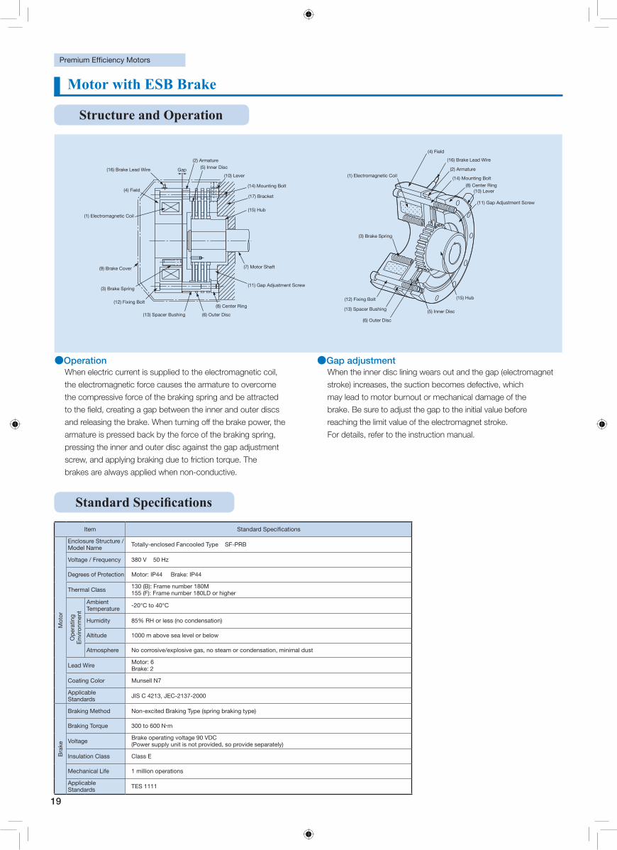
●Operation When electric current is supplied to the electromagnetic coil,
the electromagnetic force causes the armature to overcome
the compressive force of the braking spring and be attracted
to the field, creating a gap between the inner and outer discs
and releasing the brake. When turning off the brake power, the
armature is pressed back by the force of the braking spring,
pressing the inner and outer disc against the gap adjustment
screw, and applying braking due to friction torque. The
brakes are always applied when non-conductive.
●Gap adjustment When the inner disc lining wears out and the gap (electromagnet
stroke) increases, the suction becomes defective, which
may lead to motor burnout or mechanical damage of the
brake. Be sure to adjust the gap to the initial value before
reaching the limit value of the electromagnet stroke.
For details, refer to the instruction manual.
(4) Field
(1) Electromagnetic Coil
(3) Brake Spring
(12) Fixing Bolt
(13) Spacer Bushing
(6) Outer Disc
(5) Inner Disc
(15) Hub
(16) Brake Lead Wire
(2) Armature
(14) Mounting Bolt
(8) Center Ring (10) Lever
(11) Gap Adjustment Screw
(2) Armature
Gap (16) Brake Lead Wire
(9) Brake Cover
(3) Brake Spring
(12) Fixing Bolt
(13) Spacer Bushing (6) Outer Disc
(8) Center Ring
(7) Motor Shaft
(1) Electromagnetic Coil
(4) Field
(11) Gap Adjustment Screw
(5) Inner Disc
(10) Lever
(14) Mounting Bolt
(17) Bracket
(15) Hub
Motor with ESB Brake
Item
Mot
or
Enclosure Structure / Model Name Totally-enclosed Fancooled Type SF-PRB
Voltage / Frequency 380 V 50 Hz
Degrees of Protection Motor: IP44 Brake: IP44
Thermal Class 130 (B): Frame number 180M 155 (F): Frame number 180LD or higher
Op
erat
ing
Env
ironm
ent
Ambient Temperature -20°C to 40°C
Humidity 85% RH or less (no condensation)
Altitude 1000 m above sea level or below
Atmosphere No corrosive/explosive gas, no steam or condensation, minimal dust
Lead Wire Motor: 6 Brake: 2
Coating Color Munsell N7
Applicable Standards JIS C 4213, JEC-2137-2000
Bra
ke
Braking Method Non-excited Braking Type (spring braking type)
Braking Torque 300 to 600 N・m
Voltage Brake operating voltage 90 VDC (Power supply unit is not provided, so provide separately)
Insulation Class Class E
Mechanical Life 1 million operations
Applicable Standards TES 1111
Structure and Operation
20
1AC200/220V
OSAKIDENGYOSYA CO_LTD.
POWER MODULEHD-120M
2
3 4
968474
66
5 6
51
41
5.5
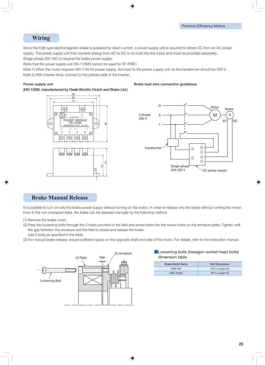
Since the ESB type electromagnetic brake is powered by direct current, a power supply unit is required to obtain DC from an AC power
supply. The power supply unit that converts energy from AC to DC is not built into the motor and must be provided separately.
Single-phase 200 VAC is required for brake power supply.
(Note that the power supply unit HD-110M3 cannot be used for SF-PRB.)
Note 1) When the motor requires 380 V 50 Hz power supply, the input to the power supply unit via the transformer should be 200 V.
Note 2) With inverter drive, connect to the primary side of the inverter.
Wiring
Power supply unit
(HD-120M, manufactured by Osaki Electric Clutch and Brake Ltd.)
Brake lead wire connection guidelines
3-phase 380 V
Single-phase 200-220 V
Transformer
Motor Brake
DC power supply
(4) Field (2) Armature
Loosening Bolt
Gap
Brake Manual Release
Brake Model Name Bolt Dimensions
ESB-220 M10 x length 60
ESB-250(S) M12 x length 65
■ Loosening bolts (hexagon socket head bolts) dimension table
It is possible to turn on only the brake power supply without turning on the motor, in order to release only the brake without running the motor. Even in the non-energized state, the brake can be released manually by the following method.
(1) Remove the brake cover. (2)
21
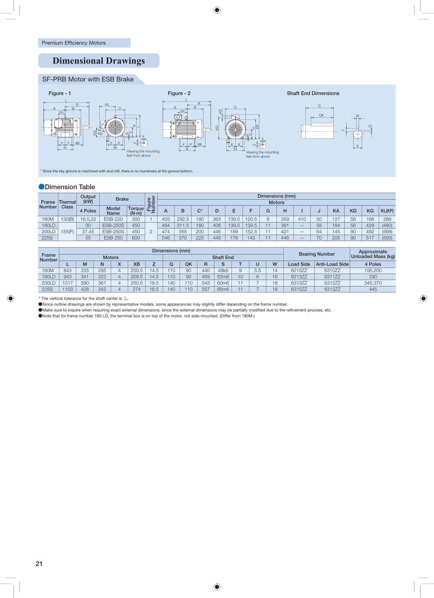
Frame Number
Thermal Class
Output (kW) Brake
Fig
ure
Num
ber Dimensions (mm)
Motors
4 Poles Model Name
Torque (N∙m) A B C* D E F G H I J KA KD KG KL(KP)
180M 130(B) 18.5,22 ESB-220 300 1 403 292.5 180 363 139.5 120.5 8 359 410 50 127 56 168 289180LD
155(F)30 ESB-250S 450
2484 311.5 180 406 139.5 139.5 11 381 — 58 184 56 429 (480)
200LD 37,45 ESB-250S 450 474 355 200 446 159 152.5 11 421 — 64 145 90 492 (568)225S 55 ESB-250 600 546 370 225 446 178 143 11 446 — 70 205 90 517 (593)
SF-PRB Motor with ESB Brake
Frame Number
Dimensions (mm) Bearing Number Approximate
Unloaded Mass (kg) Motors Shaft EndL M N X XB Z Q QK R S T U W Load Side Anti-Load Side 4 Poles
180M 843 335 285 4 209.5 14.5 110 90 440 48k6 9 5.5 14 6213ZZ 6310ZZ 195,200180LD 943 341 323 4 209.5 14.5 110 90 459 55m6 10 6 16 6213ZZ 6311ZZ 290200LD 1017 390 361 4 250.5 18.5 140 110 543 60m6 11 7 18 6313ZZ 6312ZZ 345,370225S 1103 428 342 4 274 18.5 140 110 557 65m6 11 7 18 6315ZZ 6313ZZ 445
* The vertical tolerance for the shaft center is 0−0.5.
●Since outline drawings are shown by representative models, some appearances may slightly differ depending on the frame number. ●●Note that for frame number 180 LD, the terminal box is on top of the motor, not side-mounted. (Differ from 180M.)
●Dimension Table
Figure - 1 Figure - 2 Shaft End Dimensions
XZ
KG
KLD
KD G CH I
LR
KABA
NF F XB E E
M
J
Viewing the mounting feet from above
X
Z
KA
F FN
XB E EM
J
D
G CH K
P
KD
KG
RBA
L
Viewing the mounting feet from above
W
S
U
T
QK
QW
S
U
T
QK
Q
KG
KL
D
KD G C
H I
L
R
KA
BA
N
F F XBE E
M
J
KA
F F
N
XB E E
M
J
D
G C
H
KP
KD
KG
R
BA
L
X
Z
軸端寸法図
取付足を上側より見て
取付足を上側より見て
X
Z
* Since the key groove is machined with end mill, there is no roundness at the groove bottom.
Dimensional Drawings
22
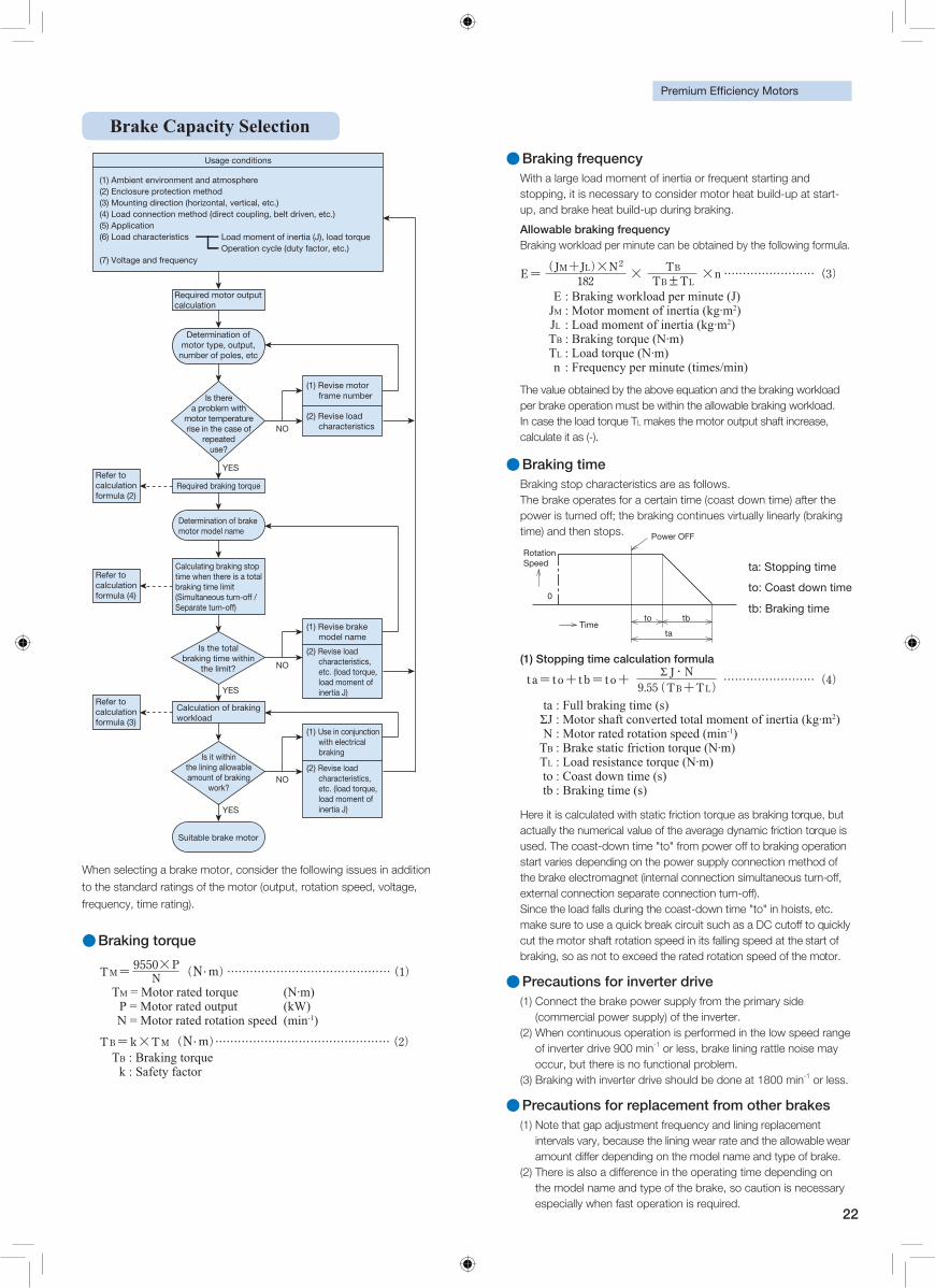
Brake Capacity Selection
Usage conditions
NO
YES
(1) Ambient environment and atmosphere (2) Enclosure protection method (3) Mounting direction (horizontal, vertical, etc.) (4) Load connection method (direct coupling, belt driven, etc.) (5) Application (6) Load characteristics
(7) Voltage and frequency
Required braking torque
Calculation of braking workload
YES
NO
YES
NO
Load moment of inertia (J), load torqueOperation cycle (duty factor, etc.)
Determination of motor type, output,
number of poles, etc
Is there a problem with
motor temperature rise in the case of
repeated use?
Is the total braking time within
the limit?
Is it within the lining allowable amount of braking
work?
Required motor output calculation
(1) Revise motor frame number
(1) Revise brake model name
(2) Revise load characteristics, etc. (load torque, load moment of inertia J)
(1) Use in conjunction with electrical braking
(2) Revise load characteristics, etc. (load torque, load moment of inertia J)
(2) Revise load characteristics
Refer to calculation formula (2)
Refer to calculation formula (4)
Refer to calculation formula (3)
Determination of brake motor model name
Calculating braking stop time when there is a total braking time limit (Simultaneous turn-off / Separate turn-off)
Suitable brake motor
When selecting a brake motor, consider the following issues in addition
to the standard ratings of the motor (output, rotation speed, voltage,
frequency, time rating).
●Braking torque
●Braking frequencyWith a large load moment of inertia or frequent starting and stopping, it is necessary to consider motor heat build-up at start-up, and brake heat build-up during braking.
Allowable braking frequencyBraking workload per minute can be obtained by the following formula.
●Braking time Braking stop characteristics are as follows. The brake operates for a certain time (coast down time) after the power is turned off; the braking continues virtually linearly (braking time) and then stops.
(1) Stopping time calculation formula
The value obtained by the above equation and the braking workload per brake operation must be within the allowable braking workload. In case the load torque TL makes the motor output shaft increase, calculate it as (-).
Here it is calculated with static friction torque as braking torque, but actually the numerical value of the average dynamic friction torque is used. The coast-down time "to" from power off to braking operation start varies depending on the power supply connection method of the brake electromagnet (internal connection simultaneous turn-off, external connection separate connection turn-off). Since the load falls during the coast-down time "to" in hoists, etc. make sure to use a quick break circuit such as a DC cutoff to quickly cut the motor shaft rotation speed in its falling speed at the start of braking, so as not to exceed the rated rotation speed of the motor.
●Precautions for inverter drive(1) Connect the brake power supply from the primary side
(commercial power supply) of the inverter. (2) When continuous operation is performed in the low speed range
of inverter drive 900 min-1 or less, brake lining rattle noise may occur, but there is no functional problem.
(3) Braking with inverter drive should be done at 1800 min-1 or less.
●Precautions for replacement from other brakes(1) Note that gap adjustment frequency and lining replacement
intervals vary, because the lining wear rate and the allowable wear amount differ depending on the model name and type of brake.
(2) There is also a difference in the operating time depending on the model name and type of the brake, so caution is necessary especially when fast operation is required.
TM N( euqrot detar rotoM = ∙m) P = Motor rated output (kW) N = Motor rated rotation speed (min-1)
TB : Braking torque k : Safety factor
)J( etunim rep daolkrow gnikarB : E JM : Motor moment of inertia (kg∙m2) JL : Load moment of inertia (kg∙m2) TB : Braking torque (N∙m) TL : Load torque (N∙m) n : Frequency per minute (times/min)
ta : Full braking time (s) ΣJ : Motor shaft converted total moment of inertia (kg∙m2) N : Motor rated rotation speed (min-1) TB : Brake static friction torque (N∙m) TL : Load resistance torque (N∙m) to : Coast down time (s) tb : Braking time (s)
Power OFF
Time
0
to tb
ta
tb: Braking time
to: Coast down time
ta: Stopping time Rotation Speed
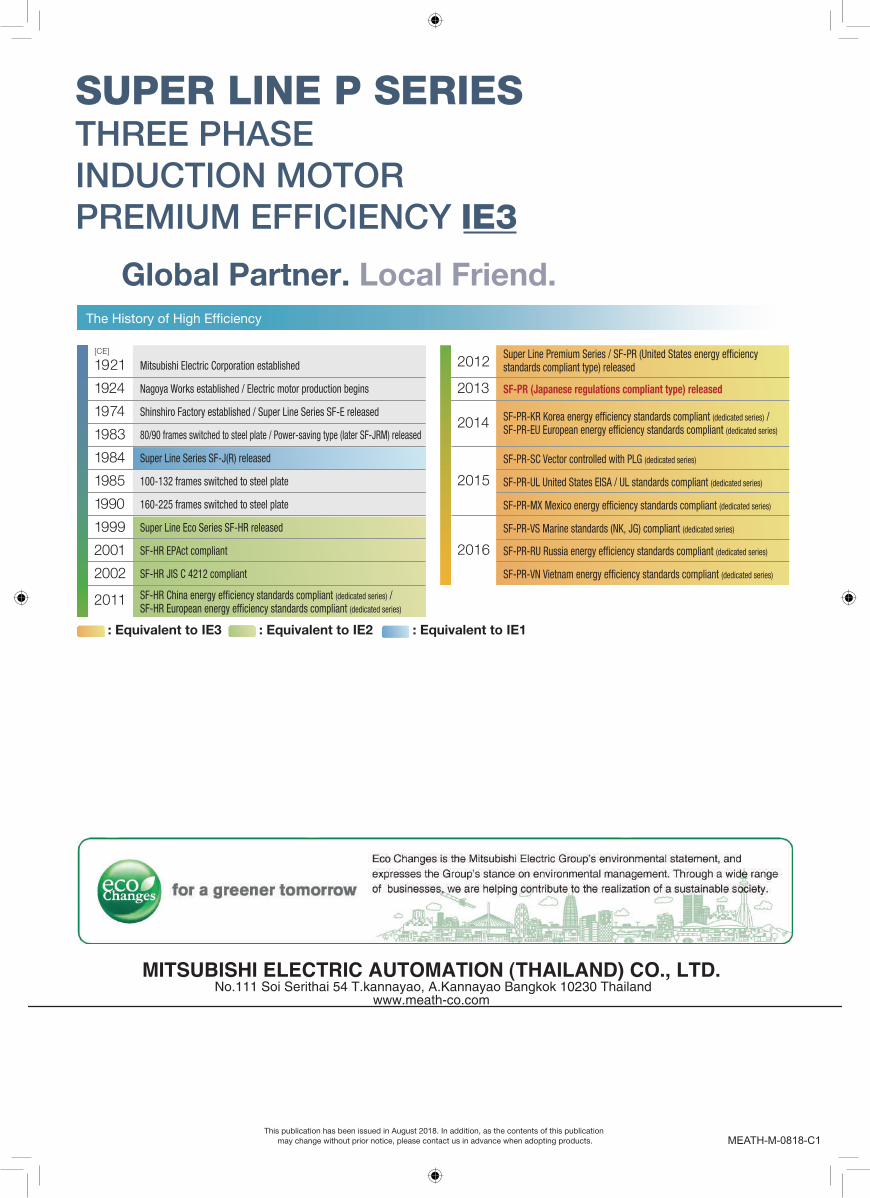
1921
1924
1974
1983
1984
1985
1990
1999
2001
2002
2011
Mitsubishi Electric Corporation established
Nagoya Works established / Electric motor production begins
Shinshiro Factory established / Super Line Series SF-E released
80/90 frames switched to steel plate / Power-saving type (later SF-JRM) released
Super Line Series SF-J(R) released
100-132 frames switched to steel plate
160-225 frames switched to steel plate
Super Line Eco Series SF-HR released
SF-HR EPAct compliant
SF-HR JIS C 4212 compliant
(dedicated series) / (dedicated series)
[CE]
: Equivalent to IE3 : Equivalent to IE2 : Equivalent to IE1
2012
2013
2014
2015
2016
Super Line Premium Series / SF-PR (United States standards compliant type) released
SF-PR (Japanese regulations compliant type) released
(dedicated series) / (dedicated series)
SF-PR-SC Vector controlled with PLG (dedicated series)
SF-PR-UL United States EISA / UL standards compliant (dedicated series)
(dedicated series)
SF-PR-VS Marine standards (NK, JG) compliant (dedicated series)
(dedicated series)
(dedicated series)
This publication has been issued in August 2018. In addition, as the contents of this publication may change without prior notice, please contact us in advance when adopting products.
SUPER LINE P SERIESTHREE PHASE INDUCTION MOTORPREMIUM EFFICIENCY IE3
MEATH-M-0818-C1
Global Partner. Local Friend.