Three dimensional transformations
63
Three-Dimensional Transformations
-
Upload
nareek -
Category
Engineering
-
view
483 -
download
1
Transcript of Three dimensional transformations

Three-Dimensional Transformations
3D transformation methods are extended from 2D methods by including considerations for the z coordinate
A 3D homogenous coordinate is represented as a four-element column vector Each geometric transformation operator is a 4 by 4 matrix
Geometric Transformations in Three-Dimensional Space
3D Translation Translation of a Point
zyx tzztyytxx
11000100010001
1
zyx
ttt
zyx
z
y
x
Prsquo=PT
(xyz) T=(txtytz)
(xrsquoyrsquozrsquo)
x
z
y
3D Scaling Uniform Scaling (Scaling relative to the coordinate
origin)
zyx szzsyysxx
11000000000000
1
zyx
ss
s
zyx
z
y
x
xz
y Prsquo = SP
Relative Scaling Scaling with a Selected fixed point (xf yf zf)
11000100010001
1000000000000
1000100010001
1
)()()(zyx
zyx
ss
s
zyx
zyx
zyxTsssSzyxTf
f
f
z
y
x
f
f
f
fffzyxfff
x x x xzzzz
y y y y
Original position Translate Scaling Inverse Translate
3D Rotation Positive rotation angles produce counterclockwise rotations
about a coordinate axis assuming that we are looking in the negative direction along that coordinate axis
Coordinate-Axis Rotations Z-axis rotation X-axis rotation Y-axis rotation
General 3D Rotations Rotation about an axis that is parallel to one of the coordinate
axes Rotation about an arbitrary axis
Coordinate-Axis Rotations Z-Axis Rotation X-Axis Rotation Y-Axis Rotation
11000010000cossin00sincos
1
zyx
zyx
110000cossin00sincos00001
1
zyx
zyx
110000cos0sin00100sin0cos
1
zyx
zyx
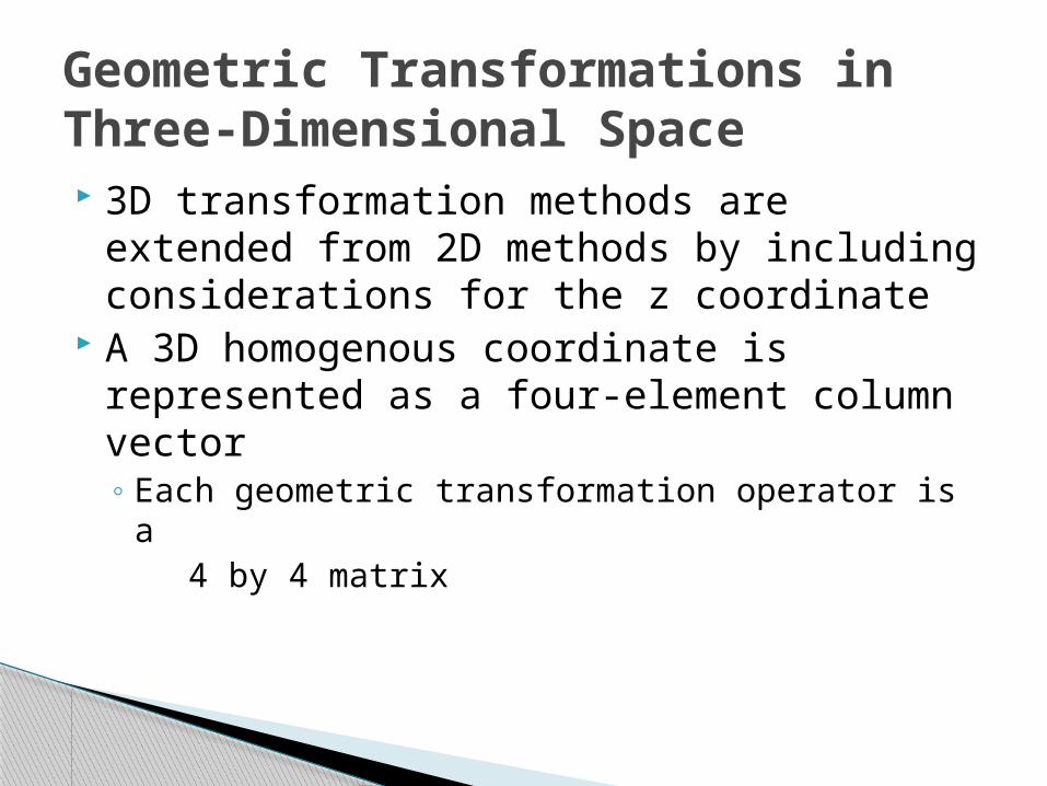
3D Rotation z-axis rotation
xrsquo=x cos θ - y sin θ yrsquo=x sin θ + y cos θ zrsquo=z
or Prsquo = Rz(θ)P
11000010000cossin00sincos
1
zyx
zyx
3D Rotation z-axis rotation
xrsquo=x cos θ - y sin θ yrsquo=x sin θ + y cos θ zrsquo=z
Other axis rotations xrarr yrarr zrarr x
x-axis rotation yrsquo=y cos θ - z sin θ zrsquo=y sin θ + z cos θ xrsquo=x
y-axis rotation zrsquo=z cos θ - x sin θ xrsquo=z sin θ + x cos θ yrsquo=y
or Prsquo = Rx(θ)P
or Prsquo = Ry(θ)P
General 3D Rotations CASE 1bull Rotation about an Axis that is Parallel to One of the Coordinate Axes
ndash Translate the object so that the rotation axis coincides with the parallel coordinate axis
ndash Perform the specified rotation about that axisndash Translate the object so that the rotation axis is moved back to its original position
ndash Any coordinate position P on the object in this fig is transformed with the sequence shown as below
Prsquo = T-1Rx(θ)TP
General 3D Rotations CASE 2 Rotation about an Arbitrary Axis
Basic Idea1 Translate (x1 y1 z1) to
the origin2 Rotate (xrsquo2 yrsquo2 zrsquo2) on to
the z axis3 Rotate the object around
the z-axis4 Rotate the axis to the
original orientation5 Translate the rotation axis
to the original position
(x2y2z2)
(x1y1z1)
x
z
y
R-1
T-1
R
T
TRRRRRTR xyzyx111
General 3D Rotations Step 1 Translation
1000100010001
1
1
1
zyx
T
(x2y2z2)
(x1y1z1)
x
z
y
General 3D Rotations Step 2 Establish [ TR ]
x x axis
100000000001
10000cossin00sincos00001
dcdbdbdc
x
R
(abc)(0bc)
Projected Point
Rotated Point
dc
cb
cdb
cb
b
22
22
cos
sin
x
y
z
cgvrkoreaackr
Arbitrary Axis Rotation Step 3 Rotate about y axis by
(abc)
(a0d)
ld
22
222222
cossin
cbd
dacballd
la
100000001000
10000cos0sin00100sin0cos
ldla
lald
y
Rx
y
Projected Point
zRotated Point
Arbitrary Axis Rotation Step 4 Rotate about z axis by the desired
angle
l
1000010000cossin00sincos
zR
y
x
z
Arbitrary Axis Rotation Step 5 Apply the reverse transformation to
place the axis back in its initial position
x
y
l
l
z
10000cos0sin00100sin0cos
10000cossin00sincos00001
1000100010001
1
1
1
111
zyx
yx RRT
TRRRRRTR xyzyx111
Find the new coordinates of a unit cube 90ordm-rotated about an axis defined by its endpoints A(210) and B(331)
A Unit Cube
Example
Example Step1 Translate point A to the origin
Arsquo(000)x
z
y
Brsquo(121)
1000010010102001
T
xz
y
l
1000
055
5520
05
52550
0001
xR
6121
55
51cos
552
52
12
2sin
222
22
lBrsquo(121)
Projected point (021)
Brdquo(105)
Example Step 2 Rotate axis ArsquoBrsquo about the x axis by
and angle until it lies on the xz plane
x
z
y
l
1000
06300
66
0010
0660
630
yR
630
65cos
66
61sin
Brdquo(10 5)(006)
Example Step 3 Rotate axis ArsquoBrsquorsquo about the y axis by
and angle until it coincides with the z axis
Example Step 4 Rotate the cube 90deg about the z axis
Finally the concatenated rotation matrix about the arbitrary axis AB becomes
TRRRRRTR xyzyx 90111
1000010000010010
90zR
100056001670741065001511075066707420
7421983007501660
1000010010102001
1000
055
5520
05
52550
0001
1000
06300
66
0010
0660
630
1000010000010010
1000
06300
66
0010
0660
630
1000
055
5520
05
52550
0001
1000010010102001
R
Example
PRP
111111110760091056007260817065003011467148304090151122511840258048405580
89129091742172528162834166716502
11111111100110010000111111001100
100056001670741065001511075066707420
7421983007501660
P
Example Multiplying R(θ) by the point matrix of the original
cube
24
A 3-D Reflection can be performed relative to a selected reflection axis or wrt selected reflection plane The 3-D reflection matrixes are set up similarly to those for 2-D
In 2-D Reflection wrt axis is equivalent to 180 degree rotations about the axis in 3- D space
whereas in 3-D Reflection wrt a plane are equivalent to 180 degree rotations in 4-D space
3D Transformation
Other Transformations REFLECTION
Other Transformations REFLECTION Reflection Relative to the XY Plane
xz
y
x
z
y
11000010000100001
1
zyx
zyx
Reflection Relative to the XZ Plane
11000010000100001
1
zyx
zyx
xz
yx
zy
11000010000100001
1
zyx
zyx
Reflection Relative to the YZ Plane
xz
y
z
y
x
Other Transformations SHEARINGbull Shearing transformation are used to modify the shape of the
object and they are useful in 3-D viewing for obtaining General Projection transformations
bull Z-axis 3-D Shear transformation
bull The effect of this transformation matrix is to alter the x and y co-ordinate values by an amount that is proportional to the z-value
while leaving z co-ordinate unchanged Boundaries of the plane that are perpendicular to z-axis are thus shifted proportional to z-value
110000100010001
1
zyx
ba
zyx
Other Transformations SHEARING
X-axis 3-D Shear transformation
Y-axis 3-D Shear transformation
110000100010001
1
zyx
b
a
zyx
110000100010001
1
zyx
ba
zyx
3D Projection
3D Transformation Slide 28
Viewing in 3D
Principle Axisbull Man-made objects often have ldquocube-likerdquo shape
These objects have 3 principle axis
3D Transformation Slide 29
3D Transformation Slide 30
Projections
bull How do we map 3D objects to 2D spaceDisplay device (a screen) is 2Dhellip
bull 2D window to world and a viewport on the 2D surface
bull Clip what wont be shown in the 2D window and map the remainder to the viewport
2D to 2D is straight
forwardhellip
bull Solution Transform 3D objects on to a 2D plane using projections
3D to 2D is more complicatedhellip
Projections
bull In 3Dhellipndash View volume in the worldndash Projection onto the 2D projection planendash A viewport to the view surface
bull Processhellipndash 1hellip clip against the view volume ndash 2hellip project to 2D plane or windowndash 3hellip map to viewport
3D Transformation Slide 31
32
Projections
bull Conceptual Model of the 3D viewing process
3D Transformation
33
PROJECTIONS
PARALLEL
(parallel projectors)PERSPECTIVE
(converging projectors)
One point(one principal vanishing point)
Two point(Two principal vanishing point)
Three point(Three principal vanishing point)
Orthographic(projectors perpendicular to view plane)
Oblique(projectors not perpendicular to view plane)
General
Cavalier
Cabinet
Multiview(view plane parallel to principal planes)
Axonometric(view plane not parallel to principal planes)
Isometric Dimetric Trimetric
3D Transformation
Types of projectionsbull 2 types of projections
ndash PERSPECTIVE and PARALLEL
bull Key factor is the center of projection ndash if distance to center of projection is finite PERSPECTIVEndash if distance to center of projection is infinite PARALLEL
3D Transformation Slide 34
35
In perspective projection object position are transformed to the view plane along lines that converge to a point called projection reference point (center of projection)
In parallel projection coordinate positions are transformed to the view plane along parallel lines
3D Transformation
bull Perspective projection+ Size varies inversely with distance - looks realisticndash Distance and angles are not (in general) preservedndash Parallel lines do not (in general) remain parallel
bull Parallel projection+ Good for exact measurements+ Parallel lines remain parallelndash Angles are not (in general) preservedndash Less realistic looking
Perspective Vs Parallel
Road in perspective
38
Perspective Projections
CHARACTERISTICS
bull Center of Projection (CP) is a finite distance from objectbull Projectors are rays (ie non-parallel)bull Vanishing pointsbull Objects appear smaller as distance from CP (eye of observer)
increasesbull Difficult to determine exact size and shape of objectbull Most realistic difficult to execute
3D Transformation
39
bull When a 3D object is projected onto view plane using perspective transformation equations any set of parallel lines in the object that are not parallel to the projection plane converge at a vanishing point ndash There are an infinite number of vanishing points
depending on how many set of parallel lines there are in the scene
bull If a set of lines are parallel to one of the three principle axes the vanishing point is called an principle vanishing point ndash There are at most 3 such points corresponding to the
number of axes cut by the projection plane
3D Transformation
40
bull Certain set of parallel lines appear to meet at a different pointndash The Vanishing point for this direction
bull Principle vanishing points are formed by the apparent intersection of lines parallel to one of the three principal x y z axes
bull The number of principal vanishing points is determined by the number of principal axes intersected by the view plane
bull Sets of parallel lines on the same plane lead to collinear vanishing points ndash The line is called the horizon for that plane
Vanishing points
3D Transformation
41
Classes of Perspective Projection
bull One-Point Perspectivebull Two-Point Perspectivebull Three-Point Perspective
3D Transformation
42
One-Point Perspective
3D Transformation
43
Two-point perspective projection
3D Transformation
44
Three-point perspective projection
bull Three-point perspective projection is used less frequently as it adds little extra realism to that offered by two-point perspective projection
3D Transformation
Affine Transformationsbull Affine transformations are combinations of hellip
ndash Linear transformations andndash Translations
bull Properties of affine transformationsndash Origin does not necessarily map to originndash Lines map to linesndash Parallel lines remain parallelndash Ratios are preservedndash Closed under composition
wyx
fedcba
wyx
100
Perspective Transformationsbull Projective transformations hellip
ndash Affine transformations andndash Projective warps
bull Properties of projective transformationsndash Origin does not necessarily map to originndash Lines map to linesndash Parallel lines do not necessarily remain parallelndash Ratios are not preservedndash Closed under composition
wyx
ihgfedcba
wyx
473D Transformation
483D Transformation
493D Transformation
503D Transformation
513D Transformation
Center of projection is at infinity Direction of projection (DOP) same for all points
Parallel Projection
DOP
ViewPlane
53
bull We can define a parallel projection with a projection vector that defines the direction for the projection lines
2 types bull Orthographic when the projection is perpendicular to the view
plane In short ndash direction of projection = normal to the projection planendash the projection is perpendicular to the view plane
bull Oblique when the projection is not perpendicular to the view plane In short ndash direction of projection normal to the projection planendash Not perpendicular
Parallel Projections
3D Transformation
54
when the projection is perpendicular to the view plane
when the projection is not perpendicular to the view plane
bull Orthographic projection Oblique projection
3D Transformation
55
ndash Front side and rear orthographic projection of an object are called elevations and the top orthographic projection is called plan view
ndash all have projection plane perpendicular to a principle axes
ndash Here length and angles are accurately depicted and measured from the drawing so engineering and architectural drawings commonly employee this
bull However As only one face of an object is shown it can be hard to create a mental image of the object even when several views are available
Orthographic (or orthogonal) projections
3D Transformation
56
Orthogonal projections
3D Transformation
57
Axonometric orthographic projections
The most common axonometric projection is an isometric projection where the projection plane intersects each coordinate axis in the model coordinate system at an equal distance
3D Transformation
58
OBLIQUE PARALLEL PROJECTIONS
3D Transformation
59
Cavalier projectionbull All lines perpendicular to the projection plane are
projected with no change in length
OBLIQUE PARALLEL PROJECTIONS Cavalier and Cabinet
3D Transformation
bull The direction of the projection makes a 45 degree angle with the projection plane
bull Because there is no foreshortening this causes an exaggeration of the z axes
Oblique Projections CAVALIER PROJECTIONbull DOP not perpendicular to view plane
Cavalier(DOP = 45o)tan() = 1
61
Cabinet projectionndash Lines which are perpendicular to the projection plane
(viewing surface) are projected at 1 2 the length ndash This results in foreshortening of the z axis and
provides a more ldquorealisticrdquo viewndash The direction of the projection makes a 634 degree
angle with the projection plane This results in foreshortening of the z axis and provides a more ldquorealisticrdquo view
3D Transformation
Oblique Projections CABINET PROJECTION
Oblique Projections CABINET PROJECTION
HampB
bull DOP not perpendicular to view plane
Cabinet(DOP = 634o)tan() = 2
633D Transformation
Remaining Topics - (REFER CLASS NOTES)
Transformation Matrix for Oblique Projection of a 3-D point
General Projection Transformations General Parallel Projection Transformation General Perspective Projection Transformation
View Volumes for Projections
- Three-Dimensional Transformations
- Geometric Transformations in Three-Dimensional Space
- 3D Translation
- 3D Scaling
- Relative Scaling
- 3D Rotation
- Coordinate-Axis Rotations
- 3D Rotation (2)
- 3D Rotation (3)
- General 3D Rotations CASE 1
- General 3D Rotations CASE 2
- General 3D Rotations
- General 3D Rotations (2)
- Arbitrary Axis Rotation
- Arbitrary Axis Rotation (2)
- Arbitrary Axis Rotation (3)
- Example
- Example (2)
- Example (3)
- Example (4)
- Example (5)
- Example (6)
- Example (7)
- Other Transformations REFLECTION
- Other Transformations REFLECTION (2)
- Other Transformations SHEARING
- Other Transformations SHEARING (2)
- 3D Projection
- Principle Axis
- Projections
- Projections
- Projections (2)
- Slide 33
- Types of projections
- In perspective projection object position are transforme
- Perspective Vs Parallel
- Road in perspective
- Perspective Projections
- Slide 39
- Vanishing points
- Classes of Perspective Projection
- One-Point Perspective
- Two-point perspective projection
- Three-point perspective projection
- Affine Transformations
- Perspective Transformations
- Slide 47
- Slide 48
- Slide 49
- Slide 50
- Slide 51
- Parallel Projection
- Parallel Projections
- Slide 54
- Orthographic (or orthogonal) projections
- Orthogonal projections
- Axonometric orthographic projections
- Slide 58
- Slide 59
- Oblique Projections CAVALIER PROJECTION
- Slide 61
- Oblique Projections CABINET PROJECTION
- Slide 63
-
3D transformation methods are extended from 2D methods by including considerations for the z coordinate
A 3D homogenous coordinate is represented as a four-element column vector Each geometric transformation operator is a 4 by 4 matrix
Geometric Transformations in Three-Dimensional Space
3D Translation Translation of a Point
zyx tzztyytxx
11000100010001
1
zyx
ttt
zyx
z
y
x
Prsquo=PT
(xyz) T=(txtytz)
(xrsquoyrsquozrsquo)
x
z
y
3D Scaling Uniform Scaling (Scaling relative to the coordinate
origin)
zyx szzsyysxx
11000000000000
1
zyx
ss
s
zyx
z
y
x
xz
y Prsquo = SP
Relative Scaling Scaling with a Selected fixed point (xf yf zf)
11000100010001
1000000000000
1000100010001
1
)()()(zyx
zyx
ss
s
zyx
zyx
zyxTsssSzyxTf
f
f
z
y
x
f
f
f
fffzyxfff
x x x xzzzz
y y y y
Original position Translate Scaling Inverse Translate
3D Rotation Positive rotation angles produce counterclockwise rotations
about a coordinate axis assuming that we are looking in the negative direction along that coordinate axis
Coordinate-Axis Rotations Z-axis rotation X-axis rotation Y-axis rotation
General 3D Rotations Rotation about an axis that is parallel to one of the coordinate
axes Rotation about an arbitrary axis
Coordinate-Axis Rotations Z-Axis Rotation X-Axis Rotation Y-Axis Rotation
11000010000cossin00sincos
1
zyx
zyx
110000cossin00sincos00001
1
zyx
zyx
110000cos0sin00100sin0cos
1
zyx
zyx
3D Rotation z-axis rotation
xrsquo=x cos θ - y sin θ yrsquo=x sin θ + y cos θ zrsquo=z
or Prsquo = Rz(θ)P
11000010000cossin00sincos
1
zyx
zyx
3D Rotation z-axis rotation
xrsquo=x cos θ - y sin θ yrsquo=x sin θ + y cos θ zrsquo=z
Other axis rotations xrarr yrarr zrarr x
x-axis rotation yrsquo=y cos θ - z sin θ zrsquo=y sin θ + z cos θ xrsquo=x
y-axis rotation zrsquo=z cos θ - x sin θ xrsquo=z sin θ + x cos θ yrsquo=y
or Prsquo = Rx(θ)P
or Prsquo = Ry(θ)P
General 3D Rotations CASE 1bull Rotation about an Axis that is Parallel to One of the Coordinate Axes
ndash Translate the object so that the rotation axis coincides with the parallel coordinate axis
ndash Perform the specified rotation about that axisndash Translate the object so that the rotation axis is moved back to its original position
ndash Any coordinate position P on the object in this fig is transformed with the sequence shown as below
Prsquo = T-1Rx(θ)TP
General 3D Rotations CASE 2 Rotation about an Arbitrary Axis
Basic Idea1 Translate (x1 y1 z1) to
the origin2 Rotate (xrsquo2 yrsquo2 zrsquo2) on to
the z axis3 Rotate the object around
the z-axis4 Rotate the axis to the
original orientation5 Translate the rotation axis
to the original position
(x2y2z2)
(x1y1z1)
x
z
y
R-1
T-1
R
T
TRRRRRTR xyzyx111
General 3D Rotations Step 1 Translation
1000100010001
1
1
1
zyx
T
(x2y2z2)
(x1y1z1)
x
z
y
General 3D Rotations Step 2 Establish [ TR ]
x x axis
100000000001
10000cossin00sincos00001
dcdbdbdc
x
R
(abc)(0bc)
Projected Point
Rotated Point
dc
cb
cdb
cb
b
22
22
cos
sin
x
y
z
cgvrkoreaackr
Arbitrary Axis Rotation Step 3 Rotate about y axis by
(abc)
(a0d)
ld
22
222222
cossin
cbd
dacballd
la
100000001000
10000cos0sin00100sin0cos
ldla
lald
y
Rx
y
Projected Point
zRotated Point
Arbitrary Axis Rotation Step 4 Rotate about z axis by the desired
angle
l
1000010000cossin00sincos
zR
y
x
z
Arbitrary Axis Rotation Step 5 Apply the reverse transformation to
place the axis back in its initial position
x
y
l
l
z
10000cos0sin00100sin0cos
10000cossin00sincos00001
1000100010001
1
1
1
111
zyx
yx RRT
TRRRRRTR xyzyx111
Find the new coordinates of a unit cube 90ordm-rotated about an axis defined by its endpoints A(210) and B(331)
A Unit Cube
Example
Example Step1 Translate point A to the origin
Arsquo(000)x
z
y
Brsquo(121)
1000010010102001
T
xz
y
l
1000
055
5520
05
52550
0001
xR
6121
55
51cos
552
52
12
2sin
222
22
lBrsquo(121)
Projected point (021)
Brdquo(105)
Example Step 2 Rotate axis ArsquoBrsquo about the x axis by
and angle until it lies on the xz plane
x
z
y
l
1000
06300
66
0010
0660
630
yR
630
65cos
66
61sin
Brdquo(10 5)(006)
Example Step 3 Rotate axis ArsquoBrsquorsquo about the y axis by
and angle until it coincides with the z axis
Example Step 4 Rotate the cube 90deg about the z axis
Finally the concatenated rotation matrix about the arbitrary axis AB becomes
TRRRRRTR xyzyx 90111
1000010000010010
90zR
100056001670741065001511075066707420
7421983007501660
1000010010102001
1000
055
5520
05
52550
0001
1000
06300
66
0010
0660
630
1000010000010010
1000
06300
66
0010
0660
630
1000
055
5520
05
52550
0001
1000010010102001
R
Example
PRP
111111110760091056007260817065003011467148304090151122511840258048405580
89129091742172528162834166716502
11111111100110010000111111001100
100056001670741065001511075066707420
7421983007501660
P
Example Multiplying R(θ) by the point matrix of the original
cube
24
A 3-D Reflection can be performed relative to a selected reflection axis or wrt selected reflection plane The 3-D reflection matrixes are set up similarly to those for 2-D
In 2-D Reflection wrt axis is equivalent to 180 degree rotations about the axis in 3- D space
whereas in 3-D Reflection wrt a plane are equivalent to 180 degree rotations in 4-D space
3D Transformation
Other Transformations REFLECTION
Other Transformations REFLECTION Reflection Relative to the XY Plane
xz
y
x
z
y
11000010000100001
1
zyx
zyx
Reflection Relative to the XZ Plane
11000010000100001
1
zyx
zyx
xz
yx
zy
11000010000100001
1
zyx
zyx
Reflection Relative to the YZ Plane
xz
y
z
y
x
Other Transformations SHEARINGbull Shearing transformation are used to modify the shape of the
object and they are useful in 3-D viewing for obtaining General Projection transformations
bull Z-axis 3-D Shear transformation
bull The effect of this transformation matrix is to alter the x and y co-ordinate values by an amount that is proportional to the z-value
while leaving z co-ordinate unchanged Boundaries of the plane that are perpendicular to z-axis are thus shifted proportional to z-value
110000100010001
1
zyx
ba
zyx
Other Transformations SHEARING
X-axis 3-D Shear transformation
Y-axis 3-D Shear transformation
110000100010001
1
zyx
b
a
zyx
110000100010001
1
zyx
ba
zyx
3D Projection
3D Transformation Slide 28
Viewing in 3D
Principle Axisbull Man-made objects often have ldquocube-likerdquo shape
These objects have 3 principle axis
3D Transformation Slide 29
3D Transformation Slide 30
Projections
bull How do we map 3D objects to 2D spaceDisplay device (a screen) is 2Dhellip
bull 2D window to world and a viewport on the 2D surface
bull Clip what wont be shown in the 2D window and map the remainder to the viewport
2D to 2D is straight
forwardhellip
bull Solution Transform 3D objects on to a 2D plane using projections
3D to 2D is more complicatedhellip
Projections
bull In 3Dhellipndash View volume in the worldndash Projection onto the 2D projection planendash A viewport to the view surface
bull Processhellipndash 1hellip clip against the view volume ndash 2hellip project to 2D plane or windowndash 3hellip map to viewport
3D Transformation Slide 31
32
Projections
bull Conceptual Model of the 3D viewing process
3D Transformation
33
PROJECTIONS
PARALLEL
(parallel projectors)PERSPECTIVE
(converging projectors)
One point(one principal vanishing point)
Two point(Two principal vanishing point)
Three point(Three principal vanishing point)
Orthographic(projectors perpendicular to view plane)
Oblique(projectors not perpendicular to view plane)
General
Cavalier
Cabinet
Multiview(view plane parallel to principal planes)
Axonometric(view plane not parallel to principal planes)
Isometric Dimetric Trimetric
3D Transformation
Types of projectionsbull 2 types of projections
ndash PERSPECTIVE and PARALLEL
bull Key factor is the center of projection ndash if distance to center of projection is finite PERSPECTIVEndash if distance to center of projection is infinite PARALLEL
3D Transformation Slide 34
35
In perspective projection object position are transformed to the view plane along lines that converge to a point called projection reference point (center of projection)
In parallel projection coordinate positions are transformed to the view plane along parallel lines
3D Transformation
bull Perspective projection+ Size varies inversely with distance - looks realisticndash Distance and angles are not (in general) preservedndash Parallel lines do not (in general) remain parallel
bull Parallel projection+ Good for exact measurements+ Parallel lines remain parallelndash Angles are not (in general) preservedndash Less realistic looking
Perspective Vs Parallel
Road in perspective
38
Perspective Projections
CHARACTERISTICS
bull Center of Projection (CP) is a finite distance from objectbull Projectors are rays (ie non-parallel)bull Vanishing pointsbull Objects appear smaller as distance from CP (eye of observer)
increasesbull Difficult to determine exact size and shape of objectbull Most realistic difficult to execute
3D Transformation
39
bull When a 3D object is projected onto view plane using perspective transformation equations any set of parallel lines in the object that are not parallel to the projection plane converge at a vanishing point ndash There are an infinite number of vanishing points
depending on how many set of parallel lines there are in the scene
bull If a set of lines are parallel to one of the three principle axes the vanishing point is called an principle vanishing point ndash There are at most 3 such points corresponding to the
number of axes cut by the projection plane
3D Transformation
40
bull Certain set of parallel lines appear to meet at a different pointndash The Vanishing point for this direction
bull Principle vanishing points are formed by the apparent intersection of lines parallel to one of the three principal x y z axes
bull The number of principal vanishing points is determined by the number of principal axes intersected by the view plane
bull Sets of parallel lines on the same plane lead to collinear vanishing points ndash The line is called the horizon for that plane
Vanishing points
3D Transformation
41
Classes of Perspective Projection
bull One-Point Perspectivebull Two-Point Perspectivebull Three-Point Perspective
3D Transformation
42
One-Point Perspective
3D Transformation
43
Two-point perspective projection
3D Transformation
44
Three-point perspective projection
bull Three-point perspective projection is used less frequently as it adds little extra realism to that offered by two-point perspective projection
3D Transformation
Affine Transformationsbull Affine transformations are combinations of hellip
ndash Linear transformations andndash Translations
bull Properties of affine transformationsndash Origin does not necessarily map to originndash Lines map to linesndash Parallel lines remain parallelndash Ratios are preservedndash Closed under composition
wyx
fedcba
wyx
100
Perspective Transformationsbull Projective transformations hellip
ndash Affine transformations andndash Projective warps
bull Properties of projective transformationsndash Origin does not necessarily map to originndash Lines map to linesndash Parallel lines do not necessarily remain parallelndash Ratios are not preservedndash Closed under composition
wyx
ihgfedcba
wyx
473D Transformation
483D Transformation
493D Transformation
503D Transformation
513D Transformation
Center of projection is at infinity Direction of projection (DOP) same for all points
Parallel Projection
DOP
ViewPlane
53
bull We can define a parallel projection with a projection vector that defines the direction for the projection lines
2 types bull Orthographic when the projection is perpendicular to the view
plane In short ndash direction of projection = normal to the projection planendash the projection is perpendicular to the view plane
bull Oblique when the projection is not perpendicular to the view plane In short ndash direction of projection normal to the projection planendash Not perpendicular
Parallel Projections
3D Transformation
54
when the projection is perpendicular to the view plane
when the projection is not perpendicular to the view plane
bull Orthographic projection Oblique projection
3D Transformation
55
ndash Front side and rear orthographic projection of an object are called elevations and the top orthographic projection is called plan view
ndash all have projection plane perpendicular to a principle axes
ndash Here length and angles are accurately depicted and measured from the drawing so engineering and architectural drawings commonly employee this
bull However As only one face of an object is shown it can be hard to create a mental image of the object even when several views are available
Orthographic (or orthogonal) projections
3D Transformation
56
Orthogonal projections
3D Transformation
57
Axonometric orthographic projections
The most common axonometric projection is an isometric projection where the projection plane intersects each coordinate axis in the model coordinate system at an equal distance
3D Transformation
58
OBLIQUE PARALLEL PROJECTIONS
3D Transformation
59
Cavalier projectionbull All lines perpendicular to the projection plane are
projected with no change in length
OBLIQUE PARALLEL PROJECTIONS Cavalier and Cabinet
3D Transformation
bull The direction of the projection makes a 45 degree angle with the projection plane
bull Because there is no foreshortening this causes an exaggeration of the z axes
Oblique Projections CAVALIER PROJECTIONbull DOP not perpendicular to view plane
Cavalier(DOP = 45o)tan() = 1
61
Cabinet projectionndash Lines which are perpendicular to the projection plane
(viewing surface) are projected at 1 2 the length ndash This results in foreshortening of the z axis and
provides a more ldquorealisticrdquo viewndash The direction of the projection makes a 634 degree
angle with the projection plane This results in foreshortening of the z axis and provides a more ldquorealisticrdquo view
3D Transformation
Oblique Projections CABINET PROJECTION
Oblique Projections CABINET PROJECTION
HampB
bull DOP not perpendicular to view plane
Cabinet(DOP = 634o)tan() = 2
633D Transformation
Remaining Topics - (REFER CLASS NOTES)
Transformation Matrix for Oblique Projection of a 3-D point
General Projection Transformations General Parallel Projection Transformation General Perspective Projection Transformation
View Volumes for Projections
- Three-Dimensional Transformations
- Geometric Transformations in Three-Dimensional Space
- 3D Translation
- 3D Scaling
- Relative Scaling
- 3D Rotation
- Coordinate-Axis Rotations
- 3D Rotation (2)
- 3D Rotation (3)
- General 3D Rotations CASE 1
- General 3D Rotations CASE 2
- General 3D Rotations
- General 3D Rotations (2)
- Arbitrary Axis Rotation
- Arbitrary Axis Rotation (2)
- Arbitrary Axis Rotation (3)
- Example
- Example (2)
- Example (3)
- Example (4)
- Example (5)
- Example (6)
- Example (7)
- Other Transformations REFLECTION
- Other Transformations REFLECTION (2)
- Other Transformations SHEARING
- Other Transformations SHEARING (2)
- 3D Projection
- Principle Axis
- Projections
- Projections
- Projections (2)
- Slide 33
- Types of projections
- In perspective projection object position are transforme
- Perspective Vs Parallel
- Road in perspective
- Perspective Projections
- Slide 39
- Vanishing points
- Classes of Perspective Projection
- One-Point Perspective
- Two-point perspective projection
- Three-point perspective projection
- Affine Transformations
- Perspective Transformations
- Slide 47
- Slide 48
- Slide 49
- Slide 50
- Slide 51
- Parallel Projection
- Parallel Projections
- Slide 54
- Orthographic (or orthogonal) projections
- Orthogonal projections
- Axonometric orthographic projections
- Slide 58
- Slide 59
- Oblique Projections CAVALIER PROJECTION
- Slide 61
- Oblique Projections CABINET PROJECTION
- Slide 63
-
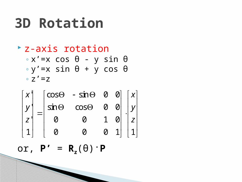
3D Rotation z-axis rotation
xrsquo=x cos θ - y sin θ yrsquo=x sin θ + y cos θ zrsquo=z
Other axis rotations xrarr yrarr zrarr x
x-axis rotation yrsquo=y cos θ - z sin θ zrsquo=y sin θ + z cos θ xrsquo=x
y-axis rotation zrsquo=z cos θ - x sin θ xrsquo=z sin θ + x cos θ yrsquo=y
or Prsquo = Rx(θ)P
or Prsquo = Ry(θ)P
General 3D Rotations CASE 1bull Rotation about an Axis that is Parallel to One of the Coordinate Axes
ndash Translate the object so that the rotation axis coincides with the parallel coordinate axis
ndash Perform the specified rotation about that axisndash Translate the object so that the rotation axis is moved back to its original position
ndash Any coordinate position P on the object in this fig is transformed with the sequence shown as below
Prsquo = T-1Rx(θ)TP
General 3D Rotations CASE 2 Rotation about an Arbitrary Axis
Basic Idea1 Translate (x1 y1 z1) to
the origin2 Rotate (xrsquo2 yrsquo2 zrsquo2) on to
the z axis3 Rotate the object around
the z-axis4 Rotate the axis to the
original orientation5 Translate the rotation axis
to the original position
(x2y2z2)
(x1y1z1)
x
z
y
R-1
T-1
R
T
TRRRRRTR xyzyx111
General 3D Rotations Step 1 Translation
1000100010001
1
1
1
zyx
T
(x2y2z2)
(x1y1z1)
x
z
y
General 3D Rotations Step 2 Establish [ TR ]
x x axis
100000000001
10000cossin00sincos00001
dcdbdbdc
x
R
(abc)(0bc)
Projected Point
Rotated Point
dc
cb
cdb
cb
b
22
22
cos
sin
x
y
z
cgvrkoreaackr
Arbitrary Axis Rotation Step 3 Rotate about y axis by
(abc)
(a0d)
ld
22
222222
cossin
cbd
dacballd
la
100000001000
10000cos0sin00100sin0cos
ldla
lald
y
Rx
y
Projected Point
zRotated Point
Arbitrary Axis Rotation Step 4 Rotate about z axis by the desired
angle
l
1000010000cossin00sincos
zR
y
x
z
Arbitrary Axis Rotation Step 5 Apply the reverse transformation to
place the axis back in its initial position
x
y
l
l
z
10000cos0sin00100sin0cos
10000cossin00sincos00001
1000100010001
1
1
1
111
zyx
yx RRT
TRRRRRTR xyzyx111
Find the new coordinates of a unit cube 90ordm-rotated about an axis defined by its endpoints A(210) and B(331)
A Unit Cube
Example
Example Step1 Translate point A to the origin
Arsquo(000)x
z
y
Brsquo(121)
1000010010102001
T
xz
y
l
1000
055
5520
05
52550
0001
xR
6121
55
51cos
552
52
12
2sin
222
22
lBrsquo(121)
Projected point (021)
Brdquo(105)
Example Step 2 Rotate axis ArsquoBrsquo about the x axis by
and angle until it lies on the xz plane
x
z
y
l
1000
06300
66
0010
0660
630
yR
630
65cos
66
61sin
Brdquo(10 5)(006)
Example Step 3 Rotate axis ArsquoBrsquorsquo about the y axis by
and angle until it coincides with the z axis
Example Step 4 Rotate the cube 90deg about the z axis
Finally the concatenated rotation matrix about the arbitrary axis AB becomes
TRRRRRTR xyzyx 90111
1000010000010010
90zR
100056001670741065001511075066707420
7421983007501660
1000010010102001
1000
055
5520
05
52550
0001
1000
06300
66
0010
0660
630
1000010000010010
1000
06300
66
0010
0660
630
1000
055
5520
05
52550
0001
1000010010102001
R
Example
PRP
111111110760091056007260817065003011467148304090151122511840258048405580
89129091742172528162834166716502
11111111100110010000111111001100
100056001670741065001511075066707420
7421983007501660
P
Example Multiplying R(θ) by the point matrix of the original
cube
24
A 3-D Reflection can be performed relative to a selected reflection axis or wrt selected reflection plane The 3-D reflection matrixes are set up similarly to those for 2-D
In 2-D Reflection wrt axis is equivalent to 180 degree rotations about the axis in 3- D space
whereas in 3-D Reflection wrt a plane are equivalent to 180 degree rotations in 4-D space
3D Transformation
Other Transformations REFLECTION
Other Transformations REFLECTION Reflection Relative to the XY Plane
xz
y
x
z
y
11000010000100001
1
zyx
zyx
Reflection Relative to the XZ Plane
11000010000100001
1
zyx
zyx
xz
yx
zy
11000010000100001
1
zyx
zyx
Reflection Relative to the YZ Plane
xz
y
z
y
x
Other Transformations SHEARINGbull Shearing transformation are used to modify the shape of the
object and they are useful in 3-D viewing for obtaining General Projection transformations
bull Z-axis 3-D Shear transformation
bull The effect of this transformation matrix is to alter the x and y co-ordinate values by an amount that is proportional to the z-value
while leaving z co-ordinate unchanged Boundaries of the plane that are perpendicular to z-axis are thus shifted proportional to z-value
110000100010001
1
zyx
ba
zyx
Other Transformations SHEARING
X-axis 3-D Shear transformation
Y-axis 3-D Shear transformation
110000100010001
1
zyx
b
a
zyx
110000100010001
1
zyx
ba
zyx
3D Projection
3D Transformation Slide 28
Viewing in 3D
Principle Axisbull Man-made objects often have ldquocube-likerdquo shape
These objects have 3 principle axis
3D Transformation Slide 29
3D Transformation Slide 30
Projections
bull How do we map 3D objects to 2D spaceDisplay device (a screen) is 2Dhellip
bull 2D window to world and a viewport on the 2D surface
bull Clip what wont be shown in the 2D window and map the remainder to the viewport
2D to 2D is straight
forwardhellip
bull Solution Transform 3D objects on to a 2D plane using projections
3D to 2D is more complicatedhellip
Projections
bull In 3Dhellipndash View volume in the worldndash Projection onto the 2D projection planendash A viewport to the view surface
bull Processhellipndash 1hellip clip against the view volume ndash 2hellip project to 2D plane or windowndash 3hellip map to viewport
3D Transformation Slide 31
32
Projections
bull Conceptual Model of the 3D viewing process
3D Transformation
33
PROJECTIONS
PARALLEL
(parallel projectors)PERSPECTIVE
(converging projectors)
One point(one principal vanishing point)
Two point(Two principal vanishing point)
Three point(Three principal vanishing point)
Orthographic(projectors perpendicular to view plane)
Oblique(projectors not perpendicular to view plane)
General
Cavalier
Cabinet
Multiview(view plane parallel to principal planes)
Axonometric(view plane not parallel to principal planes)
Isometric Dimetric Trimetric
3D Transformation
Types of projectionsbull 2 types of projections
ndash PERSPECTIVE and PARALLEL
bull Key factor is the center of projection ndash if distance to center of projection is finite PERSPECTIVEndash if distance to center of projection is infinite PARALLEL
3D Transformation Slide 34
35
In perspective projection object position are transformed to the view plane along lines that converge to a point called projection reference point (center of projection)
In parallel projection coordinate positions are transformed to the view plane along parallel lines
3D Transformation
bull Perspective projection+ Size varies inversely with distance - looks realisticndash Distance and angles are not (in general) preservedndash Parallel lines do not (in general) remain parallel
bull Parallel projection+ Good for exact measurements+ Parallel lines remain parallelndash Angles are not (in general) preservedndash Less realistic looking
Perspective Vs Parallel
Road in perspective
38
Perspective Projections
CHARACTERISTICS
bull Center of Projection (CP) is a finite distance from objectbull Projectors are rays (ie non-parallel)bull Vanishing pointsbull Objects appear smaller as distance from CP (eye of observer)
increasesbull Difficult to determine exact size and shape of objectbull Most realistic difficult to execute
3D Transformation
39
bull When a 3D object is projected onto view plane using perspective transformation equations any set of parallel lines in the object that are not parallel to the projection plane converge at a vanishing point ndash There are an infinite number of vanishing points
depending on how many set of parallel lines there are in the scene
bull If a set of lines are parallel to one of the three principle axes the vanishing point is called an principle vanishing point ndash There are at most 3 such points corresponding to the
number of axes cut by the projection plane
3D Transformation
40
bull Certain set of parallel lines appear to meet at a different pointndash The Vanishing point for this direction
bull Principle vanishing points are formed by the apparent intersection of lines parallel to one of the three principal x y z axes
bull The number of principal vanishing points is determined by the number of principal axes intersected by the view plane
bull Sets of parallel lines on the same plane lead to collinear vanishing points ndash The line is called the horizon for that plane
Vanishing points
3D Transformation
41
Classes of Perspective Projection
bull One-Point Perspectivebull Two-Point Perspectivebull Three-Point Perspective
3D Transformation
42
One-Point Perspective
3D Transformation
43
Two-point perspective projection
3D Transformation
44
Three-point perspective projection
bull Three-point perspective projection is used less frequently as it adds little extra realism to that offered by two-point perspective projection
3D Transformation
Affine Transformationsbull Affine transformations are combinations of hellip
ndash Linear transformations andndash Translations
bull Properties of affine transformationsndash Origin does not necessarily map to originndash Lines map to linesndash Parallel lines remain parallelndash Ratios are preservedndash Closed under composition
wyx
fedcba
wyx
100
Perspective Transformationsbull Projective transformations hellip
ndash Affine transformations andndash Projective warps
bull Properties of projective transformationsndash Origin does not necessarily map to originndash Lines map to linesndash Parallel lines do not necessarily remain parallelndash Ratios are not preservedndash Closed under composition
wyx
ihgfedcba
wyx
473D Transformation
483D Transformation
493D Transformation
503D Transformation
513D Transformation
Center of projection is at infinity Direction of projection (DOP) same for all points
Parallel Projection
DOP
ViewPlane
53
bull We can define a parallel projection with a projection vector that defines the direction for the projection lines
2 types bull Orthographic when the projection is perpendicular to the view
plane In short ndash direction of projection = normal to the projection planendash the projection is perpendicular to the view plane
bull Oblique when the projection is not perpendicular to the view plane In short ndash direction of projection normal to the projection planendash Not perpendicular
Parallel Projections
3D Transformation
54
when the projection is perpendicular to the view plane
when the projection is not perpendicular to the view plane
bull Orthographic projection Oblique projection
3D Transformation
55
ndash Front side and rear orthographic projection of an object are called elevations and the top orthographic projection is called plan view
ndash all have projection plane perpendicular to a principle axes
ndash Here length and angles are accurately depicted and measured from the drawing so engineering and architectural drawings commonly employee this
bull However As only one face of an object is shown it can be hard to create a mental image of the object even when several views are available
Orthographic (or orthogonal) projections
3D Transformation
56
Orthogonal projections
3D Transformation
57
Axonometric orthographic projections
The most common axonometric projection is an isometric projection where the projection plane intersects each coordinate axis in the model coordinate system at an equal distance
3D Transformation
58
OBLIQUE PARALLEL PROJECTIONS
3D Transformation
59
Cavalier projectionbull All lines perpendicular to the projection plane are
projected with no change in length
OBLIQUE PARALLEL PROJECTIONS Cavalier and Cabinet
3D Transformation
bull The direction of the projection makes a 45 degree angle with the projection plane
bull Because there is no foreshortening this causes an exaggeration of the z axes
Oblique Projections CAVALIER PROJECTIONbull DOP not perpendicular to view plane
Cavalier(DOP = 45o)tan() = 1
61
Cabinet projectionndash Lines which are perpendicular to the projection plane
(viewing surface) are projected at 1 2 the length ndash This results in foreshortening of the z axis and
provides a more ldquorealisticrdquo viewndash The direction of the projection makes a 634 degree
angle with the projection plane This results in foreshortening of the z axis and provides a more ldquorealisticrdquo view
3D Transformation
Oblique Projections CABINET PROJECTION
Oblique Projections CABINET PROJECTION
HampB
bull DOP not perpendicular to view plane
Cabinet(DOP = 634o)tan() = 2
633D Transformation
Remaining Topics - (REFER CLASS NOTES)
Transformation Matrix for Oblique Projection of a 3-D point
General Projection Transformations General Parallel Projection Transformation General Perspective Projection Transformation
View Volumes for Projections
- Three-Dimensional Transformations
- Geometric Transformations in Three-Dimensional Space
- 3D Translation
- 3D Scaling
- Relative Scaling
- 3D Rotation
- Coordinate-Axis Rotations
- 3D Rotation (2)
- 3D Rotation (3)
- General 3D Rotations CASE 1
- General 3D Rotations CASE 2
- General 3D Rotations
- General 3D Rotations (2)
- Arbitrary Axis Rotation
- Arbitrary Axis Rotation (2)
- Arbitrary Axis Rotation (3)
- Example
- Example (2)
- Example (3)
- Example (4)
- Example (5)
- Example (6)
- Example (7)
- Other Transformations REFLECTION
- Other Transformations REFLECTION (2)
- Other Transformations SHEARING
- Other Transformations SHEARING (2)
- 3D Projection
- Principle Axis
- Projections
- Projections
- Projections (2)
- Slide 33
- Types of projections
- In perspective projection object position are transforme
- Perspective Vs Parallel
- Road in perspective
- Perspective Projections
- Slide 39
- Vanishing points
- Classes of Perspective Projection
- One-Point Perspective
- Two-point perspective projection
- Three-point perspective projection
- Affine Transformations
- Perspective Transformations
- Slide 47
- Slide 48
- Slide 49
- Slide 50
- Slide 51
- Parallel Projection
- Parallel Projections
- Slide 54
- Orthographic (or orthogonal) projections
- Orthogonal projections
- Axonometric orthographic projections
- Slide 58
- Slide 59
- Oblique Projections CAVALIER PROJECTION
- Slide 61
- Oblique Projections CABINET PROJECTION
- Slide 63
-
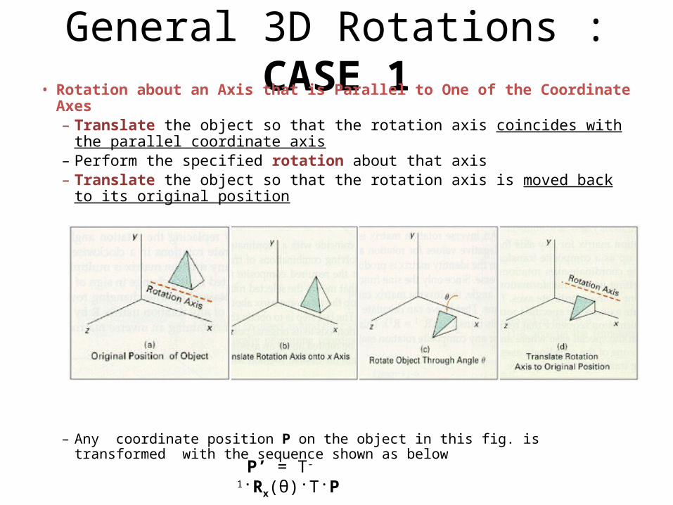
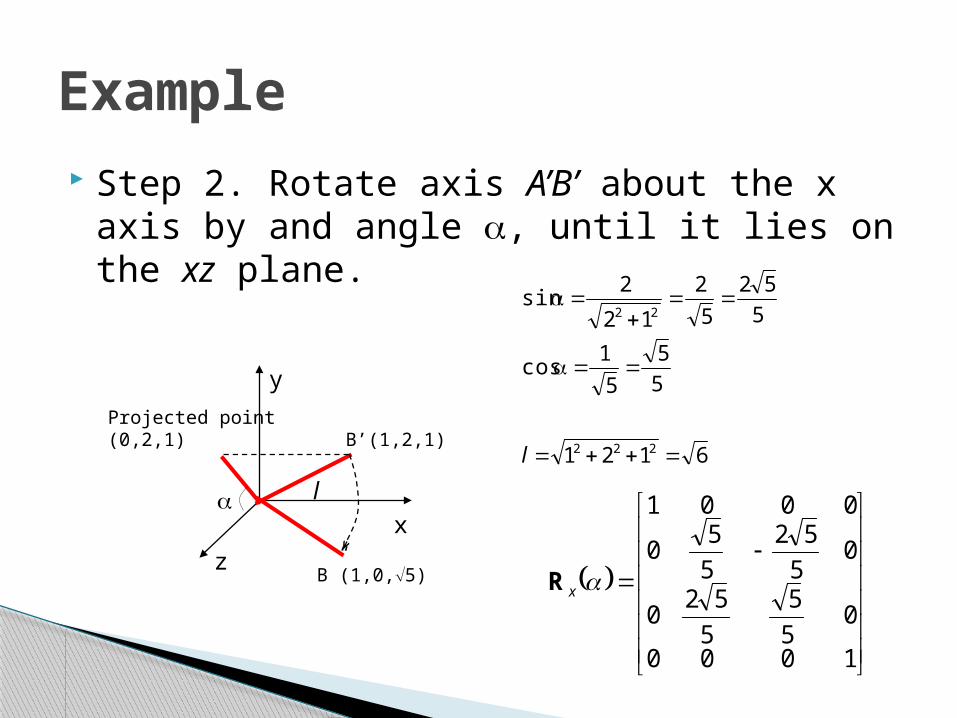
xz
y
l
1000
055
5520
05
52550
0001
xR
6121
55
51cos
552
52
12
2sin
222
22
lBrsquo(121)
Projected point (021)
Brdquo(105)
Example Step 2 Rotate axis ArsquoBrsquo about the x axis by
and angle until it lies on the xz plane
x
z
y
l
1000
06300
66
0010
0660
630
yR
630
65cos
66
61sin
Brdquo(10 5)(006)
Example Step 3 Rotate axis ArsquoBrsquorsquo about the y axis by
and angle until it coincides with the z axis
Example Step 4 Rotate the cube 90deg about the z axis
Finally the concatenated rotation matrix about the arbitrary axis AB becomes
TRRRRRTR xyzyx 90111
1000010000010010
90zR
100056001670741065001511075066707420
7421983007501660
1000010010102001
1000
055
5520
05
52550
0001
1000
06300
66
0010
0660
630
1000010000010010
1000
06300
66
0010
0660
630
1000
055
5520
05
52550
0001
1000010010102001
R
Example
PRP
111111110760091056007260817065003011467148304090151122511840258048405580
89129091742172528162834166716502
11111111100110010000111111001100
100056001670741065001511075066707420
7421983007501660
P
Example Multiplying R(θ) by the point matrix of the original
cube
24
A 3-D Reflection can be performed relative to a selected reflection axis or wrt selected reflection plane The 3-D reflection matrixes are set up similarly to those for 2-D
In 2-D Reflection wrt axis is equivalent to 180 degree rotations about the axis in 3- D space
whereas in 3-D Reflection wrt a plane are equivalent to 180 degree rotations in 4-D space
3D Transformation
Other Transformations REFLECTION
Other Transformations REFLECTION Reflection Relative to the XY Plane
xz
y
x
z
y
11000010000100001
1
zyx
zyx
Reflection Relative to the XZ Plane
11000010000100001
1
zyx
zyx
xz
yx
zy
11000010000100001
1
zyx
zyx
Reflection Relative to the YZ Plane
xz
y
z
y
x
Other Transformations SHEARINGbull Shearing transformation are used to modify the shape of the
object and they are useful in 3-D viewing for obtaining General Projection transformations
bull Z-axis 3-D Shear transformation
bull The effect of this transformation matrix is to alter the x and y co-ordinate values by an amount that is proportional to the z-value
while leaving z co-ordinate unchanged Boundaries of the plane that are perpendicular to z-axis are thus shifted proportional to z-value
110000100010001
1
zyx
ba
zyx
Other Transformations SHEARING
X-axis 3-D Shear transformation
Y-axis 3-D Shear transformation
110000100010001
1
zyx
b
a
zyx
110000100010001
1
zyx
ba
zyx
3D Projection
3D Transformation Slide 28
Viewing in 3D
Principle Axisbull Man-made objects often have ldquocube-likerdquo shape
These objects have 3 principle axis
3D Transformation Slide 29
3D Transformation Slide 30
Projections
bull How do we map 3D objects to 2D spaceDisplay device (a screen) is 2Dhellip
bull 2D window to world and a viewport on the 2D surface
bull Clip what wont be shown in the 2D window and map the remainder to the viewport
2D to 2D is straight
forwardhellip
bull Solution Transform 3D objects on to a 2D plane using projections
3D to 2D is more complicatedhellip
Projections
bull In 3Dhellipndash View volume in the worldndash Projection onto the 2D projection planendash A viewport to the view surface
bull Processhellipndash 1hellip clip against the view volume ndash 2hellip project to 2D plane or windowndash 3hellip map to viewport
3D Transformation Slide 31
32
Projections
bull Conceptual Model of the 3D viewing process
3D Transformation
33
PROJECTIONS
PARALLEL
(parallel projectors)PERSPECTIVE
(converging projectors)
One point(one principal vanishing point)
Two point(Two principal vanishing point)
Three point(Three principal vanishing point)
Orthographic(projectors perpendicular to view plane)
Oblique(projectors not perpendicular to view plane)
General
Cavalier
Cabinet
Multiview(view plane parallel to principal planes)
Axonometric(view plane not parallel to principal planes)
Isometric Dimetric Trimetric
3D Transformation
Types of projectionsbull 2 types of projections
ndash PERSPECTIVE and PARALLEL
bull Key factor is the center of projection ndash if distance to center of projection is finite PERSPECTIVEndash if distance to center of projection is infinite PARALLEL
3D Transformation Slide 34
35
In perspective projection object position are transformed to the view plane along lines that converge to a point called projection reference point (center of projection)
In parallel projection coordinate positions are transformed to the view plane along parallel lines
3D Transformation
bull Perspective projection+ Size varies inversely with distance - looks realisticndash Distance and angles are not (in general) preservedndash Parallel lines do not (in general) remain parallel
bull Parallel projection+ Good for exact measurements+ Parallel lines remain parallelndash Angles are not (in general) preservedndash Less realistic looking
Perspective Vs Parallel
Road in perspective
38
Perspective Projections
CHARACTERISTICS
bull Center of Projection (CP) is a finite distance from objectbull Projectors are rays (ie non-parallel)bull Vanishing pointsbull Objects appear smaller as distance from CP (eye of observer)
increasesbull Difficult to determine exact size and shape of objectbull Most realistic difficult to execute
3D Transformation
39
bull When a 3D object is projected onto view plane using perspective transformation equations any set of parallel lines in the object that are not parallel to the projection plane converge at a vanishing point ndash There are an infinite number of vanishing points
depending on how many set of parallel lines there are in the scene
bull If a set of lines are parallel to one of the three principle axes the vanishing point is called an principle vanishing point ndash There are at most 3 such points corresponding to the
number of axes cut by the projection plane
3D Transformation
40
bull Certain set of parallel lines appear to meet at a different pointndash The Vanishing point for this direction
bull Principle vanishing points are formed by the apparent intersection of lines parallel to one of the three principal x y z axes
bull The number of principal vanishing points is determined by the number of principal axes intersected by the view plane
bull Sets of parallel lines on the same plane lead to collinear vanishing points ndash The line is called the horizon for that plane
Vanishing points
3D Transformation
41
Classes of Perspective Projection
bull One-Point Perspectivebull Two-Point Perspectivebull Three-Point Perspective
3D Transformation
42
One-Point Perspective
3D Transformation
43
Two-point perspective projection
3D Transformation
44
Three-point perspective projection
bull Three-point perspective projection is used less frequently as it adds little extra realism to that offered by two-point perspective projection
3D Transformation
Affine Transformationsbull Affine transformations are combinations of hellip
ndash Linear transformations andndash Translations
bull Properties of affine transformationsndash Origin does not necessarily map to originndash Lines map to linesndash Parallel lines remain parallelndash Ratios are preservedndash Closed under composition
wyx
fedcba
wyx
100
Perspective Transformationsbull Projective transformations hellip
ndash Affine transformations andndash Projective warps
bull Properties of projective transformationsndash Origin does not necessarily map to originndash Lines map to linesndash Parallel lines do not necessarily remain parallelndash Ratios are not preservedndash Closed under composition
wyx
ihgfedcba
wyx
473D Transformation
483D Transformation
493D Transformation
503D Transformation
513D Transformation
Center of projection is at infinity Direction of projection (DOP) same for all points
Parallel Projection
DOP
ViewPlane
53
bull We can define a parallel projection with a projection vector that defines the direction for the projection lines
2 types bull Orthographic when the projection is perpendicular to the view
plane In short ndash direction of projection = normal to the projection planendash the projection is perpendicular to the view plane
bull Oblique when the projection is not perpendicular to the view plane In short ndash direction of projection normal to the projection planendash Not perpendicular
Parallel Projections
3D Transformation
54
when the projection is perpendicular to the view plane
when the projection is not perpendicular to the view plane
bull Orthographic projection Oblique projection
3D Transformation
55
ndash Front side and rear orthographic projection of an object are called elevations and the top orthographic projection is called plan view
ndash all have projection plane perpendicular to a principle axes
ndash Here length and angles are accurately depicted and measured from the drawing so engineering and architectural drawings commonly employee this
bull However As only one face of an object is shown it can be hard to create a mental image of the object even when several views are available
Orthographic (or orthogonal) projections
3D Transformation
56
Orthogonal projections
3D Transformation
57
Axonometric orthographic projections
The most common axonometric projection is an isometric projection where the projection plane intersects each coordinate axis in the model coordinate system at an equal distance
3D Transformation
58
OBLIQUE PARALLEL PROJECTIONS
3D Transformation
59
Cavalier projectionbull All lines perpendicular to the projection plane are
projected with no change in length
OBLIQUE PARALLEL PROJECTIONS Cavalier and Cabinet
3D Transformation
bull The direction of the projection makes a 45 degree angle with the projection plane
bull Because there is no foreshortening this causes an exaggeration of the z axes
Oblique Projections CAVALIER PROJECTIONbull DOP not perpendicular to view plane
Cavalier(DOP = 45o)tan() = 1
61
Cabinet projectionndash Lines which are perpendicular to the projection plane
(viewing surface) are projected at 1 2 the length ndash This results in foreshortening of the z axis and
provides a more ldquorealisticrdquo viewndash The direction of the projection makes a 634 degree
angle with the projection plane This results in foreshortening of the z axis and provides a more ldquorealisticrdquo view
3D Transformation
Oblique Projections CABINET PROJECTION
Oblique Projections CABINET PROJECTION
HampB
bull DOP not perpendicular to view plane
Cabinet(DOP = 634o)tan() = 2
633D Transformation
Remaining Topics - (REFER CLASS NOTES)
Transformation Matrix for Oblique Projection of a 3-D point
General Projection Transformations General Parallel Projection Transformation General Perspective Projection Transformation
View Volumes for Projections
- Three-Dimensional Transformations
- Geometric Transformations in Three-Dimensional Space
- 3D Translation
- 3D Scaling
- Relative Scaling
- 3D Rotation
- Coordinate-Axis Rotations
- 3D Rotation (2)
- 3D Rotation (3)
- General 3D Rotations CASE 1
- General 3D Rotations CASE 2
- General 3D Rotations
- General 3D Rotations (2)
- Arbitrary Axis Rotation
- Arbitrary Axis Rotation (2)
- Arbitrary Axis Rotation (3)
- Example
- Example (2)
- Example (3)
- Example (4)
- Example (5)
- Example (6)
- Example (7)
- Other Transformations REFLECTION
- Other Transformations REFLECTION (2)
- Other Transformations SHEARING
- Other Transformations SHEARING (2)
- 3D Projection
- Principle Axis
- Projections
- Projections
- Projections (2)
- Slide 33
- Types of projections
- In perspective projection object position are transforme
- Perspective Vs Parallel
- Road in perspective
- Perspective Projections
- Slide 39
- Vanishing points
- Classes of Perspective Projection
- One-Point Perspective
- Two-point perspective projection
- Three-point perspective projection
- Affine Transformations
- Perspective Transformations
- Slide 47
- Slide 48
- Slide 49
- Slide 50
- Slide 51
- Parallel Projection
- Parallel Projections
- Slide 54
- Orthographic (or orthogonal) projections
- Orthogonal projections
- Axonometric orthographic projections
- Slide 58
- Slide 59
- Oblique Projections CAVALIER PROJECTION
- Slide 61
- Oblique Projections CABINET PROJECTION
- Slide 63
-

x
z
y
l
1000
06300
66
0010
0660
630
yR
630
65cos
66
61sin
Brdquo(10 5)(006)
Example Step 3 Rotate axis ArsquoBrsquorsquo about the y axis by
and angle until it coincides with the z axis
Example Step 4 Rotate the cube 90deg about the z axis
Finally the concatenated rotation matrix about the arbitrary axis AB becomes
TRRRRRTR xyzyx 90111
1000010000010010
90zR
100056001670741065001511075066707420
7421983007501660
1000010010102001
1000
055
5520
05
52550
0001
1000
06300
66
0010
0660
630
1000010000010010
1000
06300
66
0010
0660
630
1000
055
5520
05
52550
0001
1000010010102001
R
Example
PRP
111111110760091056007260817065003011467148304090151122511840258048405580
89129091742172528162834166716502
11111111100110010000111111001100
100056001670741065001511075066707420
7421983007501660
P
Example Multiplying R(θ) by the point matrix of the original
cube
24
A 3-D Reflection can be performed relative to a selected reflection axis or wrt selected reflection plane The 3-D reflection matrixes are set up similarly to those for 2-D
In 2-D Reflection wrt axis is equivalent to 180 degree rotations about the axis in 3- D space
whereas in 3-D Reflection wrt a plane are equivalent to 180 degree rotations in 4-D space
3D Transformation
Other Transformations REFLECTION
Other Transformations REFLECTION Reflection Relative to the XY Plane
xz
y
x
z
y
11000010000100001
1
zyx
zyx
Reflection Relative to the XZ Plane
11000010000100001
1
zyx
zyx
xz
yx
zy
11000010000100001
1
zyx
zyx
Reflection Relative to the YZ Plane
xz
y
z
y
x
Other Transformations SHEARINGbull Shearing transformation are used to modify the shape of the
object and they are useful in 3-D viewing for obtaining General Projection transformations
bull Z-axis 3-D Shear transformation
bull The effect of this transformation matrix is to alter the x and y co-ordinate values by an amount that is proportional to the z-value
while leaving z co-ordinate unchanged Boundaries of the plane that are perpendicular to z-axis are thus shifted proportional to z-value
110000100010001
1
zyx
ba
zyx
Other Transformations SHEARING
X-axis 3-D Shear transformation
Y-axis 3-D Shear transformation
110000100010001
1
zyx
b
a
zyx
110000100010001
1
zyx
ba
zyx
3D Projection
3D Transformation Slide 28
Viewing in 3D
Principle Axisbull Man-made objects often have ldquocube-likerdquo shape
These objects have 3 principle axis
3D Transformation Slide 29
3D Transformation Slide 30
Projections
bull How do we map 3D objects to 2D spaceDisplay device (a screen) is 2Dhellip
bull 2D window to world and a viewport on the 2D surface
bull Clip what wont be shown in the 2D window and map the remainder to the viewport
2D to 2D is straight
forwardhellip
bull Solution Transform 3D objects on to a 2D plane using projections
3D to 2D is more complicatedhellip
Projections
bull In 3Dhellipndash View volume in the worldndash Projection onto the 2D projection planendash A viewport to the view surface
bull Processhellipndash 1hellip clip against the view volume ndash 2hellip project to 2D plane or windowndash 3hellip map to viewport
3D Transformation Slide 31
32
Projections
bull Conceptual Model of the 3D viewing process
3D Transformation
33
PROJECTIONS
PARALLEL
(parallel projectors)PERSPECTIVE
(converging projectors)
One point(one principal vanishing point)
Two point(Two principal vanishing point)
Three point(Three principal vanishing point)
Orthographic(projectors perpendicular to view plane)
Oblique(projectors not perpendicular to view plane)
General
Cavalier
Cabinet
Multiview(view plane parallel to principal planes)
Axonometric(view plane not parallel to principal planes)
Isometric Dimetric Trimetric
3D Transformation
Types of projectionsbull 2 types of projections
ndash PERSPECTIVE and PARALLEL
bull Key factor is the center of projection ndash if distance to center of projection is finite PERSPECTIVEndash if distance to center of projection is infinite PARALLEL
3D Transformation Slide 34
35
In perspective projection object position are transformed to the view plane along lines that converge to a point called projection reference point (center of projection)
In parallel projection coordinate positions are transformed to the view plane along parallel lines
3D Transformation
bull Perspective projection+ Size varies inversely with distance - looks realisticndash Distance and angles are not (in general) preservedndash Parallel lines do not (in general) remain parallel
bull Parallel projection+ Good for exact measurements+ Parallel lines remain parallelndash Angles are not (in general) preservedndash Less realistic looking
Perspective Vs Parallel
Road in perspective
38
Perspective Projections
CHARACTERISTICS
bull Center of Projection (CP) is a finite distance from objectbull Projectors are rays (ie non-parallel)bull Vanishing pointsbull Objects appear smaller as distance from CP (eye of observer)
increasesbull Difficult to determine exact size and shape of objectbull Most realistic difficult to execute
3D Transformation
39
bull When a 3D object is projected onto view plane using perspective transformation equations any set of parallel lines in the object that are not parallel to the projection plane converge at a vanishing point ndash There are an infinite number of vanishing points
depending on how many set of parallel lines there are in the scene
bull If a set of lines are parallel to one of the three principle axes the vanishing point is called an principle vanishing point ndash There are at most 3 such points corresponding to the
number of axes cut by the projection plane
3D Transformation
40
bull Certain set of parallel lines appear to meet at a different pointndash The Vanishing point for this direction
bull Principle vanishing points are formed by the apparent intersection of lines parallel to one of the three principal x y z axes
bull The number of principal vanishing points is determined by the number of principal axes intersected by the view plane
bull Sets of parallel lines on the same plane lead to collinear vanishing points ndash The line is called the horizon for that plane
Vanishing points
3D Transformation
41
Classes of Perspective Projection
bull One-Point Perspectivebull Two-Point Perspectivebull Three-Point Perspective
3D Transformation
42
One-Point Perspective
3D Transformation
43
Two-point perspective projection
3D Transformation
44
Three-point perspective projection
bull Three-point perspective projection is used less frequently as it adds little extra realism to that offered by two-point perspective projection
3D Transformation
Affine Transformationsbull Affine transformations are combinations of hellip
ndash Linear transformations andndash Translations
bull Properties of affine transformationsndash Origin does not necessarily map to originndash Lines map to linesndash Parallel lines remain parallelndash Ratios are preservedndash Closed under composition
wyx
fedcba
wyx
100
Perspective Transformationsbull Projective transformations hellip
ndash Affine transformations andndash Projective warps
bull Properties of projective transformationsndash Origin does not necessarily map to originndash Lines map to linesndash Parallel lines do not necessarily remain parallelndash Ratios are not preservedndash Closed under composition
wyx
ihgfedcba
wyx
473D Transformation
483D Transformation
493D Transformation
503D Transformation
513D Transformation
Center of projection is at infinity Direction of projection (DOP) same for all points
Parallel Projection
DOP
ViewPlane
53
bull We can define a parallel projection with a projection vector that defines the direction for the projection lines
2 types bull Orthographic when the projection is perpendicular to the view
plane In short ndash direction of projection = normal to the projection planendash the projection is perpendicular to the view plane
bull Oblique when the projection is not perpendicular to the view plane In short ndash direction of projection normal to the projection planendash Not perpendicular
Parallel Projections
3D Transformation
54
when the projection is perpendicular to the view plane
when the projection is not perpendicular to the view plane
bull Orthographic projection Oblique projection
3D Transformation
55
ndash Front side and rear orthographic projection of an object are called elevations and the top orthographic projection is called plan view
ndash all have projection plane perpendicular to a principle axes
ndash Here length and angles are accurately depicted and measured from the drawing so engineering and architectural drawings commonly employee this
bull However As only one face of an object is shown it can be hard to create a mental image of the object even when several views are available
Orthographic (or orthogonal) projections
3D Transformation
56
Orthogonal projections
3D Transformation
57
Axonometric orthographic projections
The most common axonometric projection is an isometric projection where the projection plane intersects each coordinate axis in the model coordinate system at an equal distance
3D Transformation
58
OBLIQUE PARALLEL PROJECTIONS
3D Transformation
59
Cavalier projectionbull All lines perpendicular to the projection plane are
projected with no change in length
OBLIQUE PARALLEL PROJECTIONS Cavalier and Cabinet
3D Transformation
bull The direction of the projection makes a 45 degree angle with the projection plane
bull Because there is no foreshortening this causes an exaggeration of the z axes
Oblique Projections CAVALIER PROJECTIONbull DOP not perpendicular to view plane
Cavalier(DOP = 45o)tan() = 1
61
Cabinet projectionndash Lines which are perpendicular to the projection plane
(viewing surface) are projected at 1 2 the length ndash This results in foreshortening of the z axis and
provides a more ldquorealisticrdquo viewndash The direction of the projection makes a 634 degree
angle with the projection plane This results in foreshortening of the z axis and provides a more ldquorealisticrdquo view
3D Transformation
Oblique Projections CABINET PROJECTION
Oblique Projections CABINET PROJECTION
HampB
bull DOP not perpendicular to view plane
Cabinet(DOP = 634o)tan() = 2
633D Transformation
Remaining Topics - (REFER CLASS NOTES)
Transformation Matrix for Oblique Projection of a 3-D point
General Projection Transformations General Parallel Projection Transformation General Perspective Projection Transformation
View Volumes for Projections
- Three-Dimensional Transformations
- Geometric Transformations in Three-Dimensional Space
- 3D Translation
- 3D Scaling
- Relative Scaling
- 3D Rotation
- Coordinate-Axis Rotations
- 3D Rotation (2)
- 3D Rotation (3)
- General 3D Rotations CASE 1
- General 3D Rotations CASE 2
- General 3D Rotations
- General 3D Rotations (2)
- Arbitrary Axis Rotation
- Arbitrary Axis Rotation (2)
- Arbitrary Axis Rotation (3)
- Example
- Example (2)
- Example (3)
- Example (4)
- Example (5)
- Example (6)
- Example (7)
- Other Transformations REFLECTION
- Other Transformations REFLECTION (2)
- Other Transformations SHEARING
- Other Transformations SHEARING (2)
- 3D Projection
- Principle Axis
- Projections
- Projections
- Projections (2)
- Slide 33
- Types of projections
- In perspective projection object position are transforme
- Perspective Vs Parallel
- Road in perspective
- Perspective Projections
- Slide 39
- Vanishing points
- Classes of Perspective Projection
- One-Point Perspective
- Two-point perspective projection
- Three-point perspective projection
- Affine Transformations
- Perspective Transformations
- Slide 47
- Slide 48
- Slide 49
- Slide 50
- Slide 51
- Parallel Projection
- Parallel Projections
- Slide 54
- Orthographic (or orthogonal) projections
- Orthogonal projections
- Axonometric orthographic projections
- Slide 58
- Slide 59
- Oblique Projections CAVALIER PROJECTION
- Slide 61
- Oblique Projections CABINET PROJECTION
- Slide 63
-

100056001670741065001511075066707420
7421983007501660
1000010010102001
1000
055
5520
05
52550
0001
1000
06300
66
0010
0660
630
1000010000010010
1000
06300
66
0010
0660
630
1000
055
5520
05
52550
0001
1000010010102001
R
Example
PRP
111111110760091056007260817065003011467148304090151122511840258048405580
89129091742172528162834166716502
11111111100110010000111111001100
100056001670741065001511075066707420
7421983007501660
P
Example Multiplying R(θ) by the point matrix of the original
cube
24
A 3-D Reflection can be performed relative to a selected reflection axis or wrt selected reflection plane The 3-D reflection matrixes are set up similarly to those for 2-D
In 2-D Reflection wrt axis is equivalent to 180 degree rotations about the axis in 3- D space
whereas in 3-D Reflection wrt a plane are equivalent to 180 degree rotations in 4-D space
3D Transformation
Other Transformations REFLECTION
Other Transformations REFLECTION Reflection Relative to the XY Plane
xz
y
x
z
y
11000010000100001
1
zyx
zyx
Reflection Relative to the XZ Plane
11000010000100001
1
zyx
zyx
xz
yx
zy
11000010000100001
1
zyx
zyx
Reflection Relative to the YZ Plane
xz
y
z
y
x
Other Transformations SHEARINGbull Shearing transformation are used to modify the shape of the
object and they are useful in 3-D viewing for obtaining General Projection transformations
bull Z-axis 3-D Shear transformation
bull The effect of this transformation matrix is to alter the x and y co-ordinate values by an amount that is proportional to the z-value
while leaving z co-ordinate unchanged Boundaries of the plane that are perpendicular to z-axis are thus shifted proportional to z-value
110000100010001
1
zyx
ba
zyx
Other Transformations SHEARING
X-axis 3-D Shear transformation
Y-axis 3-D Shear transformation
110000100010001
1
zyx
b
a
zyx
110000100010001
1
zyx
ba
zyx
3D Projection
3D Transformation Slide 28
Viewing in 3D
Principle Axisbull Man-made objects often have ldquocube-likerdquo shape
These objects have 3 principle axis
3D Transformation Slide 29
3D Transformation Slide 30
Projections
bull How do we map 3D objects to 2D spaceDisplay device (a screen) is 2Dhellip
bull 2D window to world and a viewport on the 2D surface
bull Clip what wont be shown in the 2D window and map the remainder to the viewport
2D to 2D is straight
forwardhellip
bull Solution Transform 3D objects on to a 2D plane using projections
3D to 2D is more complicatedhellip
Projections
bull In 3Dhellipndash View volume in the worldndash Projection onto the 2D projection planendash A viewport to the view surface
bull Processhellipndash 1hellip clip against the view volume ndash 2hellip project to 2D plane or windowndash 3hellip map to viewport
3D Transformation Slide 31
32
Projections
bull Conceptual Model of the 3D viewing process
3D Transformation
33
PROJECTIONS
PARALLEL
(parallel projectors)PERSPECTIVE
(converging projectors)
One point(one principal vanishing point)
Two point(Two principal vanishing point)
Three point(Three principal vanishing point)
Orthographic(projectors perpendicular to view plane)
Oblique(projectors not perpendicular to view plane)
General
Cavalier
Cabinet
Multiview(view plane parallel to principal planes)
Axonometric(view plane not parallel to principal planes)
Isometric Dimetric Trimetric
3D Transformation
Types of projectionsbull 2 types of projections
ndash PERSPECTIVE and PARALLEL
bull Key factor is the center of projection ndash if distance to center of projection is finite PERSPECTIVEndash if distance to center of projection is infinite PARALLEL
3D Transformation Slide 34
35
In perspective projection object position are transformed to the view plane along lines that converge to a point called projection reference point (center of projection)
In parallel projection coordinate positions are transformed to the view plane along parallel lines
3D Transformation
bull Perspective projection+ Size varies inversely with distance - looks realisticndash Distance and angles are not (in general) preservedndash Parallel lines do not (in general) remain parallel
bull Parallel projection+ Good for exact measurements+ Parallel lines remain parallelndash Angles are not (in general) preservedndash Less realistic looking
Perspective Vs Parallel
Road in perspective
38
Perspective Projections
CHARACTERISTICS
bull Center of Projection (CP) is a finite distance from objectbull Projectors are rays (ie non-parallel)bull Vanishing pointsbull Objects appear smaller as distance from CP (eye of observer)
increasesbull Difficult to determine exact size and shape of objectbull Most realistic difficult to execute
3D Transformation
39
bull When a 3D object is projected onto view plane using perspective transformation equations any set of parallel lines in the object that are not parallel to the projection plane converge at a vanishing point ndash There are an infinite number of vanishing points
depending on how many set of parallel lines there are in the scene
bull If a set of lines are parallel to one of the three principle axes the vanishing point is called an principle vanishing point ndash There are at most 3 such points corresponding to the
number of axes cut by the projection plane
3D Transformation
40
bull Certain set of parallel lines appear to meet at a different pointndash The Vanishing point for this direction
bull Principle vanishing points are formed by the apparent intersection of lines parallel to one of the three principal x y z axes
bull The number of principal vanishing points is determined by the number of principal axes intersected by the view plane
bull Sets of parallel lines on the same plane lead to collinear vanishing points ndash The line is called the horizon for that plane
Vanishing points
3D Transformation
41
Classes of Perspective Projection
bull One-Point Perspectivebull Two-Point Perspectivebull Three-Point Perspective
3D Transformation
42
One-Point Perspective
3D Transformation
43
Two-point perspective projection
3D Transformation
44
Three-point perspective projection
bull Three-point perspective projection is used less frequently as it adds little extra realism to that offered by two-point perspective projection
3D Transformation
Affine Transformationsbull Affine transformations are combinations of hellip
ndash Linear transformations andndash Translations
bull Properties of affine transformationsndash Origin does not necessarily map to originndash Lines map to linesndash Parallel lines remain parallelndash Ratios are preservedndash Closed under composition
wyx
fedcba
wyx
100
Perspective Transformationsbull Projective transformations hellip
ndash Affine transformations andndash Projective warps
bull Properties of projective transformationsndash Origin does not necessarily map to originndash Lines map to linesndash Parallel lines do not necessarily remain parallelndash Ratios are not preservedndash Closed under composition
wyx
ihgfedcba
wyx
473D Transformation
483D Transformation
493D Transformation
503D Transformation
513D Transformation
Center of projection is at infinity Direction of projection (DOP) same for all points
Parallel Projection
DOP
ViewPlane
53
bull We can define a parallel projection with a projection vector that defines the direction for the projection lines
2 types bull Orthographic when the projection is perpendicular to the view
plane In short ndash direction of projection = normal to the projection planendash the projection is perpendicular to the view plane
bull Oblique when the projection is not perpendicular to the view plane In short ndash direction of projection normal to the projection planendash Not perpendicular
Parallel Projections
3D Transformation
54
when the projection is perpendicular to the view plane
when the projection is not perpendicular to the view plane
bull Orthographic projection Oblique projection
3D Transformation
55
ndash Front side and rear orthographic projection of an object are called elevations and the top orthographic projection is called plan view
ndash all have projection plane perpendicular to a principle axes
ndash Here length and angles are accurately depicted and measured from the drawing so engineering and architectural drawings commonly employee this
bull However As only one face of an object is shown it can be hard to create a mental image of the object even when several views are available
Orthographic (or orthogonal) projections
3D Transformation
56
Orthogonal projections
3D Transformation
57
Axonometric orthographic projections
The most common axonometric projection is an isometric projection where the projection plane intersects each coordinate axis in the model coordinate system at an equal distance
3D Transformation
58
OBLIQUE PARALLEL PROJECTIONS
3D Transformation
59
Cavalier projectionbull All lines perpendicular to the projection plane are
projected with no change in length
OBLIQUE PARALLEL PROJECTIONS Cavalier and Cabinet
3D Transformation
bull The direction of the projection makes a 45 degree angle with the projection plane
bull Because there is no foreshortening this causes an exaggeration of the z axes
Oblique Projections CAVALIER PROJECTIONbull DOP not perpendicular to view plane
Cavalier(DOP = 45o)tan() = 1
61
Cabinet projectionndash Lines which are perpendicular to the projection plane
(viewing surface) are projected at 1 2 the length ndash This results in foreshortening of the z axis and
provides a more ldquorealisticrdquo viewndash The direction of the projection makes a 634 degree
angle with the projection plane This results in foreshortening of the z axis and provides a more ldquorealisticrdquo view
3D Transformation
Oblique Projections CABINET PROJECTION
Oblique Projections CABINET PROJECTION
HampB
bull DOP not perpendicular to view plane
Cabinet(DOP = 634o)tan() = 2
633D Transformation
Remaining Topics - (REFER CLASS NOTES)
Transformation Matrix for Oblique Projection of a 3-D point
General Projection Transformations General Parallel Projection Transformation General Perspective Projection Transformation
View Volumes for Projections
- Three-Dimensional Transformations
- Geometric Transformations in Three-Dimensional Space
- 3D Translation
- 3D Scaling
- Relative Scaling
- 3D Rotation
- Coordinate-Axis Rotations
- 3D Rotation (2)
- 3D Rotation (3)
- General 3D Rotations CASE 1
- General 3D Rotations CASE 2
- General 3D Rotations
- General 3D Rotations (2)
- Arbitrary Axis Rotation
- Arbitrary Axis Rotation (2)
- Arbitrary Axis Rotation (3)
- Example
- Example (2)
- Example (3)
- Example (4)
- Example (5)
- Example (6)
- Example (7)
- Other Transformations REFLECTION
- Other Transformations REFLECTION (2)
- Other Transformations SHEARING
- Other Transformations SHEARING (2)
- 3D Projection
- Principle Axis
- Projections
- Projections
- Projections (2)
- Slide 33
- Types of projections
- In perspective projection object position are transforme
- Perspective Vs Parallel
- Road in perspective
- Perspective Projections
- Slide 39
- Vanishing points
- Classes of Perspective Projection
- One-Point Perspective
- Two-point perspective projection
- Three-point perspective projection
- Affine Transformations
- Perspective Transformations
- Slide 47
- Slide 48
- Slide 49
- Slide 50
- Slide 51
- Parallel Projection
- Parallel Projections
- Slide 54
- Orthographic (or orthogonal) projections
- Orthogonal projections
- Axonometric orthographic projections
- Slide 58
- Slide 59
- Oblique Projections CAVALIER PROJECTION
- Slide 61
- Oblique Projections CABINET PROJECTION
- Slide 63
-
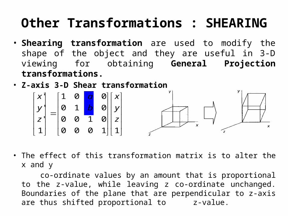
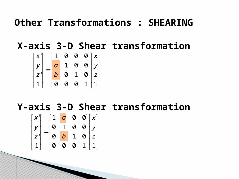
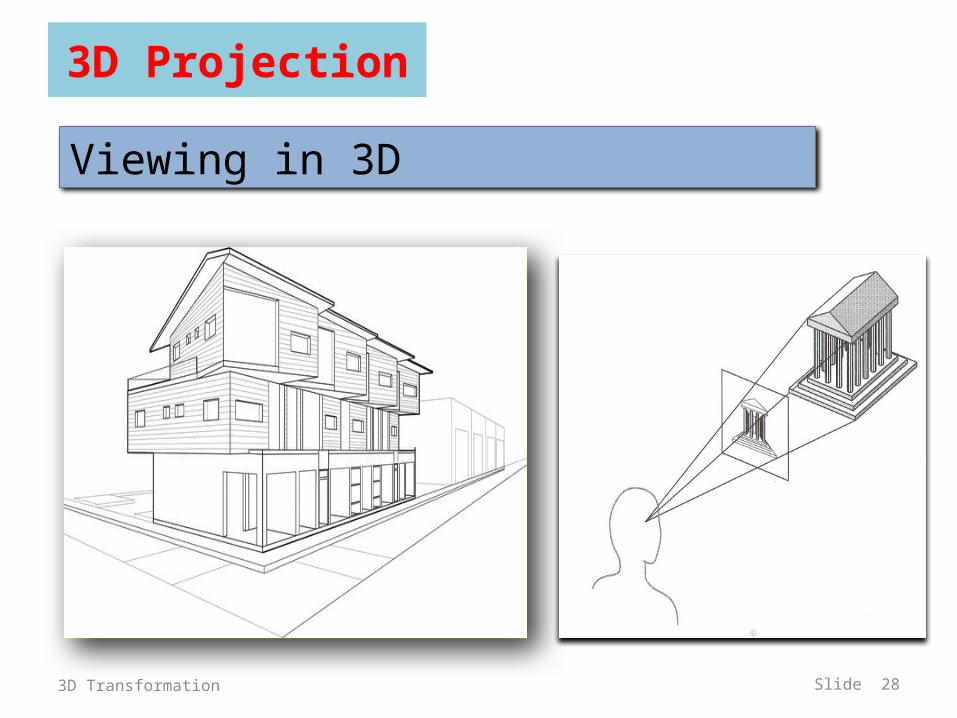

Projections
bull In 3Dhellipndash View volume in the worldndash Projection onto the 2D projection planendash A viewport to the view surface
bull Processhellipndash 1hellip clip against the view volume ndash 2hellip project to 2D plane or windowndash 3hellip map to viewport
3D Transformation Slide 31
32
Projections
bull Conceptual Model of the 3D viewing process
3D Transformation
33
PROJECTIONS
PARALLEL
(parallel projectors)PERSPECTIVE
(converging projectors)
One point(one principal vanishing point)
Two point(Two principal vanishing point)
Three point(Three principal vanishing point)
Orthographic(projectors perpendicular to view plane)
Oblique(projectors not perpendicular to view plane)
General
Cavalier
Cabinet
Multiview(view plane parallel to principal planes)
Axonometric(view plane not parallel to principal planes)
Isometric Dimetric Trimetric
3D Transformation
Types of projectionsbull 2 types of projections
ndash PERSPECTIVE and PARALLEL
bull Key factor is the center of projection ndash if distance to center of projection is finite PERSPECTIVEndash if distance to center of projection is infinite PARALLEL
3D Transformation Slide 34
35
In perspective projection object position are transformed to the view plane along lines that converge to a point called projection reference point (center of projection)
In parallel projection coordinate positions are transformed to the view plane along parallel lines
3D Transformation
bull Perspective projection+ Size varies inversely with distance - looks realisticndash Distance and angles are not (in general) preservedndash Parallel lines do not (in general) remain parallel
bull Parallel projection+ Good for exact measurements+ Parallel lines remain parallelndash Angles are not (in general) preservedndash Less realistic looking
Perspective Vs Parallel
Road in perspective
38
Perspective Projections
CHARACTERISTICS
bull Center of Projection (CP) is a finite distance from objectbull Projectors are rays (ie non-parallel)bull Vanishing pointsbull Objects appear smaller as distance from CP (eye of observer)
increasesbull Difficult to determine exact size and shape of objectbull Most realistic difficult to execute
3D Transformation
39
bull When a 3D object is projected onto view plane using perspective transformation equations any set of parallel lines in the object that are not parallel to the projection plane converge at a vanishing point ndash There are an infinite number of vanishing points
depending on how many set of parallel lines there are in the scene
bull If a set of lines are parallel to one of the three principle axes the vanishing point is called an principle vanishing point ndash There are at most 3 such points corresponding to the
number of axes cut by the projection plane
3D Transformation
40
bull Certain set of parallel lines appear to meet at a different pointndash The Vanishing point for this direction
bull Principle vanishing points are formed by the apparent intersection of lines parallel to one of the three principal x y z axes
bull The number of principal vanishing points is determined by the number of principal axes intersected by the view plane
bull Sets of parallel lines on the same plane lead to collinear vanishing points ndash The line is called the horizon for that plane
Vanishing points
3D Transformation
41
Classes of Perspective Projection
bull One-Point Perspectivebull Two-Point Perspectivebull Three-Point Perspective
3D Transformation
42
One-Point Perspective
3D Transformation
43
Two-point perspective projection
3D Transformation
44
Three-point perspective projection
bull Three-point perspective projection is used less frequently as it adds little extra realism to that offered by two-point perspective projection
3D Transformation
Affine Transformationsbull Affine transformations are combinations of hellip
ndash Linear transformations andndash Translations
bull Properties of affine transformationsndash Origin does not necessarily map to originndash Lines map to linesndash Parallel lines remain parallelndash Ratios are preservedndash Closed under composition
wyx
fedcba
wyx
100
Perspective Transformationsbull Projective transformations hellip
ndash Affine transformations andndash Projective warps
bull Properties of projective transformationsndash Origin does not necessarily map to originndash Lines map to linesndash Parallel lines do not necessarily remain parallelndash Ratios are not preservedndash Closed under composition
wyx
ihgfedcba
wyx
473D Transformation
483D Transformation
493D Transformation
503D Transformation
513D Transformation
Center of projection is at infinity Direction of projection (DOP) same for all points
Parallel Projection
DOP
ViewPlane
53
bull We can define a parallel projection with a projection vector that defines the direction for the projection lines
2 types bull Orthographic when the projection is perpendicular to the view
plane In short ndash direction of projection = normal to the projection planendash the projection is perpendicular to the view plane
bull Oblique when the projection is not perpendicular to the view plane In short ndash direction of projection normal to the projection planendash Not perpendicular
Parallel Projections
3D Transformation
54
when the projection is perpendicular to the view plane
when the projection is not perpendicular to the view plane
bull Orthographic projection Oblique projection
3D Transformation
55
ndash Front side and rear orthographic projection of an object are called elevations and the top orthographic projection is called plan view
ndash all have projection plane perpendicular to a principle axes
ndash Here length and angles are accurately depicted and measured from the drawing so engineering and architectural drawings commonly employee this
bull However As only one face of an object is shown it can be hard to create a mental image of the object even when several views are available
Orthographic (or orthogonal) projections
3D Transformation
56
Orthogonal projections
3D Transformation
57
Axonometric orthographic projections
The most common axonometric projection is an isometric projection where the projection plane intersects each coordinate axis in the model coordinate system at an equal distance
3D Transformation
58
OBLIQUE PARALLEL PROJECTIONS
3D Transformation
59
Cavalier projectionbull All lines perpendicular to the projection plane are
projected with no change in length
OBLIQUE PARALLEL PROJECTIONS Cavalier and Cabinet
3D Transformation
bull The direction of the projection makes a 45 degree angle with the projection plane
bull Because there is no foreshortening this causes an exaggeration of the z axes
Oblique Projections CAVALIER PROJECTIONbull DOP not perpendicular to view plane
Cavalier(DOP = 45o)tan() = 1
61
Cabinet projectionndash Lines which are perpendicular to the projection plane
(viewing surface) are projected at 1 2 the length ndash This results in foreshortening of the z axis and
provides a more ldquorealisticrdquo viewndash The direction of the projection makes a 634 degree
angle with the projection plane This results in foreshortening of the z axis and provides a more ldquorealisticrdquo view
3D Transformation
Oblique Projections CABINET PROJECTION
Oblique Projections CABINET PROJECTION
HampB
bull DOP not perpendicular to view plane
Cabinet(DOP = 634o)tan() = 2
633D Transformation
Remaining Topics - (REFER CLASS NOTES)
Transformation Matrix for Oblique Projection of a 3-D point
General Projection Transformations General Parallel Projection Transformation General Perspective Projection Transformation
View Volumes for Projections
- Three-Dimensional Transformations
- Geometric Transformations in Three-Dimensional Space
- 3D Translation
- 3D Scaling
- Relative Scaling
- 3D Rotation
- Coordinate-Axis Rotations
- 3D Rotation (2)
- 3D Rotation (3)
- General 3D Rotations CASE 1
- General 3D Rotations CASE 2
- General 3D Rotations
- General 3D Rotations (2)
- Arbitrary Axis Rotation
- Arbitrary Axis Rotation (2)
- Arbitrary Axis Rotation (3)
- Example
- Example (2)
- Example (3)
- Example (4)
- Example (5)
- Example (6)
- Example (7)
- Other Transformations REFLECTION
- Other Transformations REFLECTION (2)
- Other Transformations SHEARING
- Other Transformations SHEARING (2)
- 3D Projection
- Principle Axis
- Projections
- Projections
- Projections (2)
- Slide 33
- Types of projections
- In perspective projection object position are transforme
- Perspective Vs Parallel
- Road in perspective
- Perspective Projections
- Slide 39
- Vanishing points
- Classes of Perspective Projection
- One-Point Perspective
- Two-point perspective projection
- Three-point perspective projection
- Affine Transformations
- Perspective Transformations
- Slide 47
- Slide 48
- Slide 49
- Slide 50
- Slide 51
- Parallel Projection
- Parallel Projections
- Slide 54
- Orthographic (or orthogonal) projections
- Orthogonal projections
- Axonometric orthographic projections
- Slide 58
- Slide 59
- Oblique Projections CAVALIER PROJECTION
- Slide 61
- Oblique Projections CABINET PROJECTION
- Slide 63
-
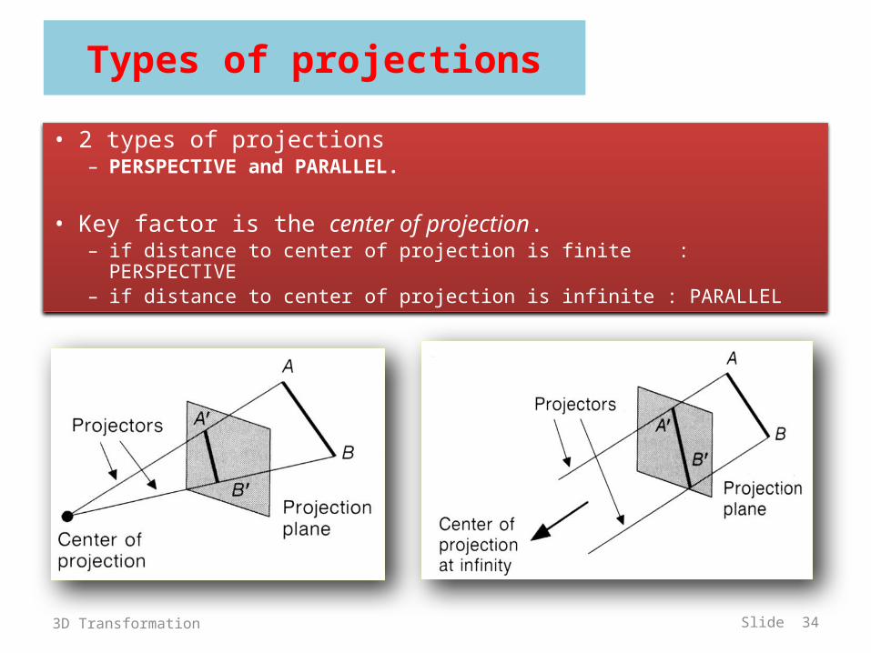
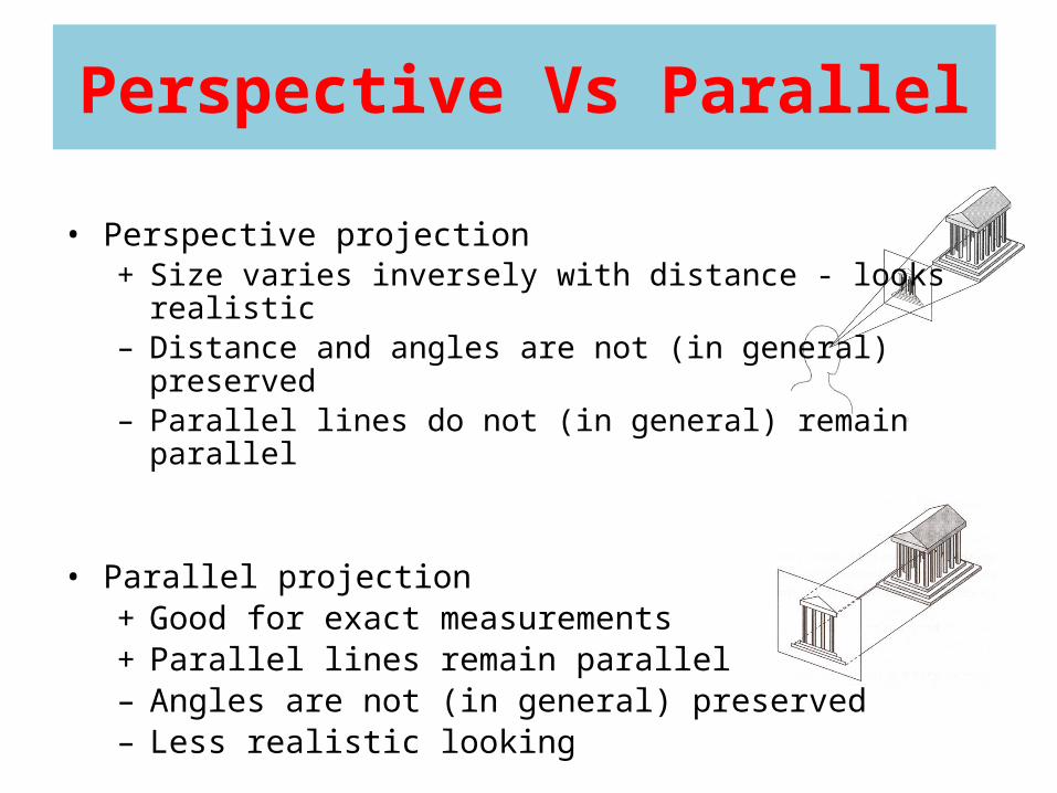
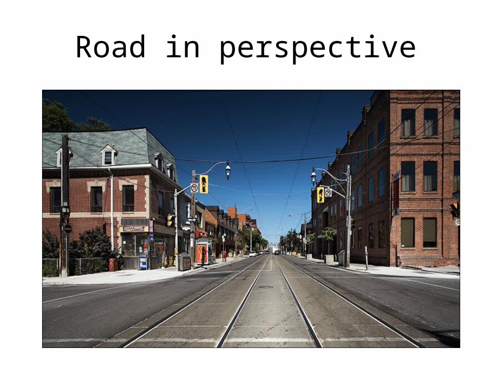
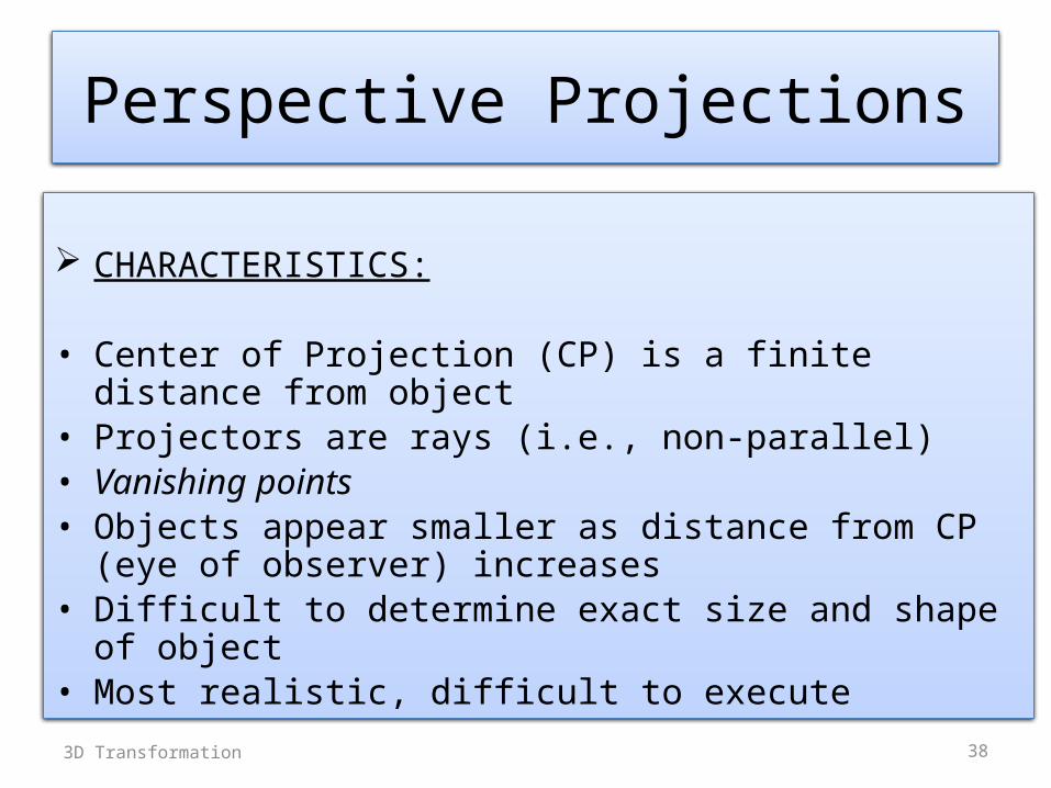
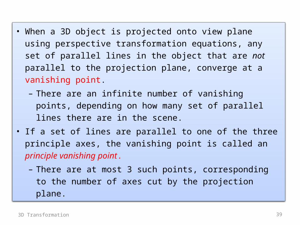
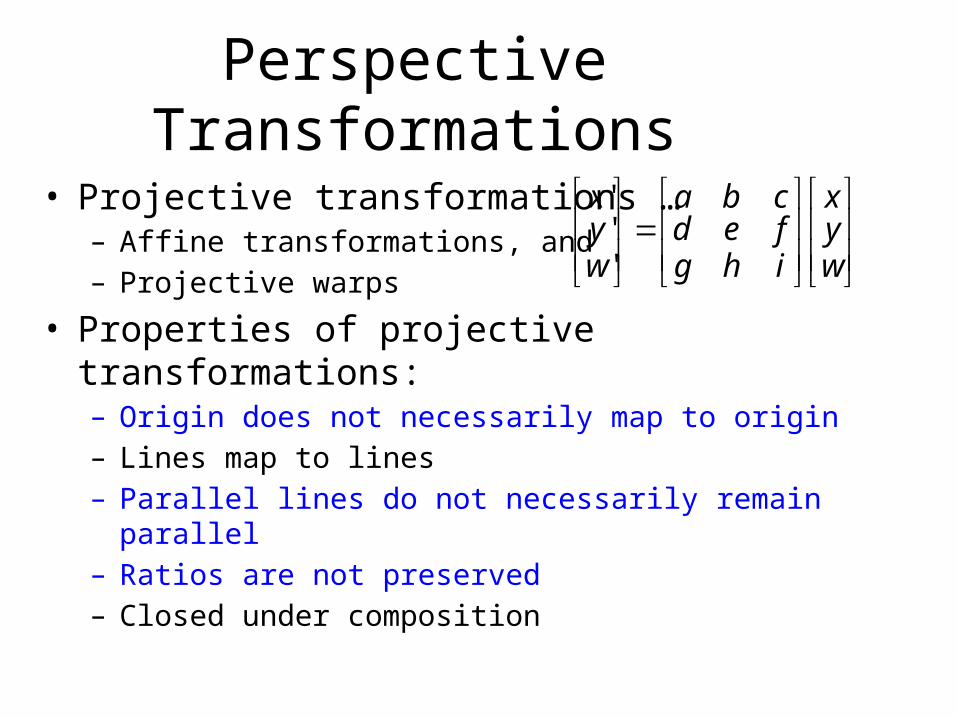
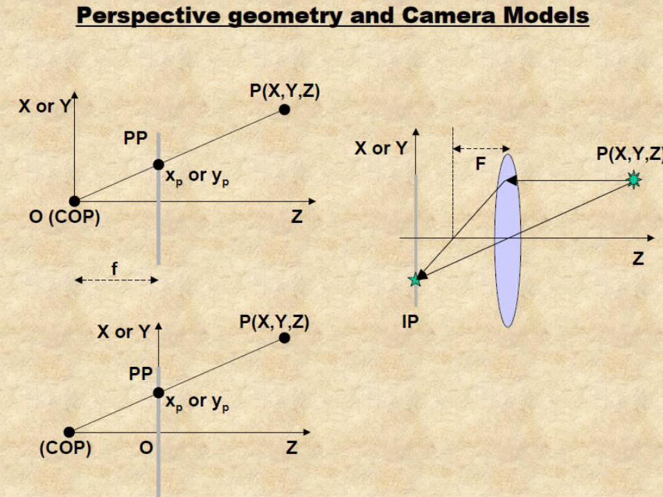
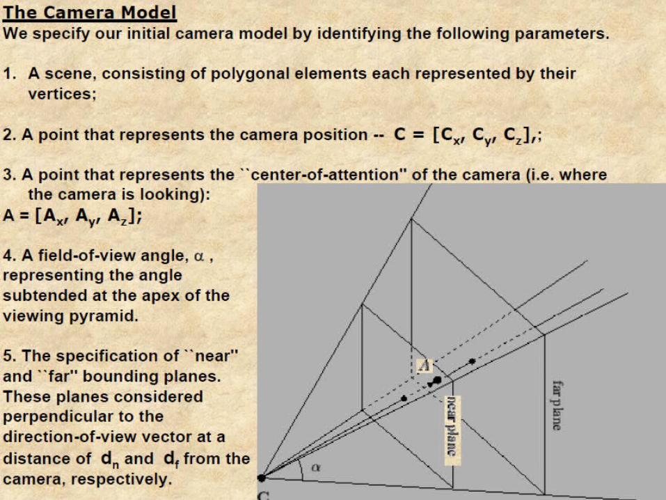
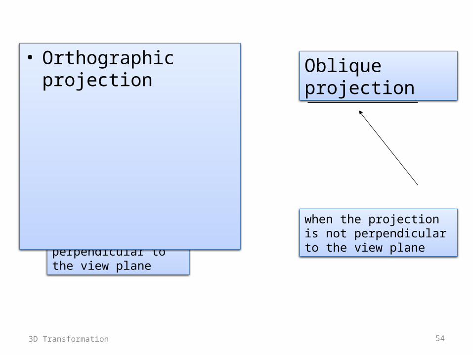
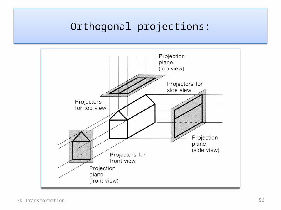
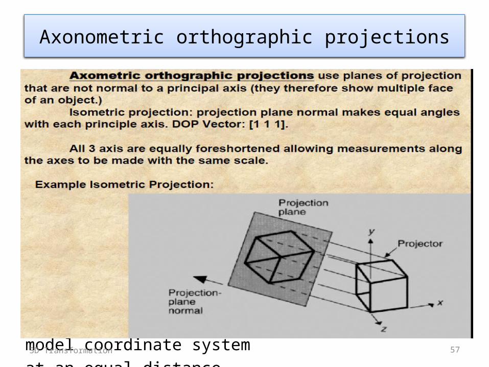