
Three-Dimensional Subband Coding with Motion …. Ohm : Three-Dimensional Subband Coding with Motion...
30
-1- Three-Dimensional Subband Coding with Motion Compensation Jens-Rainer Ohm, MEMBER, IEEE 1 IP EDICS category : 1.1 Abstract Three-dimensional (3-D) frequency coding is an alternative approach to hybrid coding concepts used in today's standards. The first part of this paper presents a study on concepts for temporal-axis frequency decomposition along the motion trajectory in video sequences. It is shown that, if a 2- band split is used, it is possible to overcome the problem of spatial inhomogeneity in the motion vector field (MVF), which occurs at the positions of uncovered and covered areas. In these cases, original pixel values from one frame are placed into the lowpass-band signal, while displaced- frame-difference values are embedded into the highpass band. This technique is applicable with arbitrary MVFs; examples with block-matching and interpolative motion compensation are given. Derivations are first performed for the example of 2-tap quadrature mirror filters (QMFs), and then generalized to any linear-phase QMFs. With 2-band analysis and synthesis stages arranged as cascade structures, higher-resolution frequency decompositions are realizable. In the second part of the paper, encoding of the temporal-axis subband signals is discussed. A parallel filterbank scheme was used for spatial subband decomposition, and adaptive lattice vector quantization was employed to approach the entropy rate of the 3-D subband samples. Coding results suggest that high-motion video sequences can be encoded at significantly lower rates, than those achievable with conventional hybrid coders. Main advantages are the high energy compaction capability and the non-recursive decoder structure. In the conclusion, the scheme is interpreted more generally, viewed as a motion-compensated short-time spectral analysis of video sequences, which can adapt to the quickness of changes. Although a 3-D multiresolution representation of the picture information is produced, a true multiresolution representation of motion information, based on spatio-temporal decimation and interpolation of the MVF, is regarded as the still-missing part. 1 Correspondence address : Dr.-Ing. Jens-Rainer Ohm Technische Universität Berlin, Institut für Fernmeldetechnik, Sekretariat FT 5 Einsteinufer 25, D-10587 Berlin, Germany Phone : +49-30-314-26800 Fax : +49-30-314-25799 Email : [email protected] This work was supported by the Deutsche Forschungsgemeinschaft (DFG) under grant No 75/24.
-
Upload
truongdang -
Category
Documents
-
view
227 -
download
3
Transcript of Three-Dimensional Subband Coding with Motion …. Ohm : Three-Dimensional Subband Coding with Motion...

-1-
Three-Dimensional Subband Coding with Motion Compensation
Jens-Rainer Ohm, MEMBER, IEEE1
IP EDICS category : 1.1
Abstract
Three-dimensional (3-D) frequency coding is an alternative approach to hybrid coding concepts
used in today's standards. The first part of this paper presents a study on concepts for temporal-axis
frequency decomposition along the motion trajectory in video sequences. It is shown that, if a 2-
band split is used, it is possible to overcome the problem of spatial inhomogeneity in the motion
vector field (MVF), which occurs at the positions of uncovered and covered areas. In these cases,
original pixel values from one frame are placed into the lowpass-band signal, while displaced-
frame-difference values are embedded into the highpass band. This technique is applicable with
arbitrary MVFs; examples with block-matching and interpolative motion compensation are given.
Derivations are first performed for the example of 2-tap quadrature mirror filters (QMFs), and then
generalized to any linear-phase QMFs. With 2-band analysis and synthesis stages arranged as
cascade structures, higher-resolution frequency decompositions are realizable. In the second part of
the paper, encoding of the temporal-axis subband signals is discussed. A parallel filterbank scheme
was used for spatial subband decomposition, and adaptive lattice vector quantization was employed
to approach the entropy rate of the 3-D subband samples. Coding results suggest that high-motion
video sequences can be encoded at significantly lower rates, than those achievable with
conventional hybrid coders. Main advantages are the high energy compaction capability and the
non-recursive decoder structure. In the conclusion, the scheme is interpreted more generally, viewed
as a motion-compensated short-time spectral analysis of video sequences, which can adapt to the
quickness of changes. Although a 3-D multiresolution representation of the picture information is
produced, a true multiresolution representation of motion information, based on spatio-temporal
decimation and interpolation of the MVF, is regarded as the still-missing part.
1Correspondence address :
Dr.-Ing. Jens-Rainer Ohm
Technische Universität Berlin, Institut für Fernmeldetechnik, Sekretariat FT 5
Einsteinufer 25, D-10587 Berlin, Germany
Phone : +49-30-314-26800 Fax : +49-30-314-25799 Email : [email protected]
This work was supported by the Deutsche Forschungsgemeinschaft (DFG) under grant No 75/24.
J.-R. Ohm : Three-Dimensional Subband Coding with Motion Compensation
-2-
Introduction
Hybrid coding, employing prediction with motion compensation (MC) along the temporal axis and
2-D DCT coding in the spatial domain, is the path that is taken in the present digital video
standardization activities [1]. Other work has been reported on "motion-compensated SBC", e.g. [2]
[3] [4]. These are all together hybrid coders, but the DCT frequency decomposition is replaced by 2-
D subband filterbanks. Indeed, SBC has emerged as a superior technique for encoding of 2-D image
signals, which can overcome the blocking artefacts inherent in DCT schemes. Transform coding
may be regarded as a special case of SBC, with the transform's basis functions interpreted as the
impulse responses of a filterbank [5].
In 3-D SBC schemes, subband decomposition must likewise be applied along the temporal axis of a
video sequence. One argument in favor of such a scheme is the nonrecursive decoder structure
(provided that FIR filterbanks are used), which avoids infinite propagation of transmission errors. If
the temporal axis decomposition is performed as the first step, the original sequence is transformed
into several subsampled sequences, each of which contains the information about a specific fre-
quency band, representing the "velocity of temporal change". If the amount of motion is low, the
amount of energy in the higher frequency component sequences will be low, and the energy com-
paction will be high even without motion adaptation. Hence, 3-D SBC schemes without motion
adaptation [6] [7] [8] have mostly been applied to videophone sequences.
If motion occurs, the correlation along the temporal filter path of the SBC analysis may be
drastically lowered. To overcome this problem, motion-adaptive 3-D SBC schemes [9] [10] [11]
[12] [13] were proposed, which apply the temporal-axis frequency decomposition only in the areas
of low motion. These schemes are not even applicable to scenes with global motion, because
intraframe encoding would inherently be performed over all frames.
To attain high energy compaction in the case of motion, it is convenient to employ motion-compen-
sated 3-D frequency coding. Schemes with global MC [14] [15] are straightforward, but lack ef-
ficiency in the cases of inhomogeneous MVFs, covered and uncovered areas. Pioneering work on 3-
D SBC and 3-D DCT with spatial-variant MC is due to Kronander [16] [17]. His schemes need an
additional encoding of a residual error signal at those frame positions, that are not hit by the motion
trajectory. A scheme denoted as MC-SBC, which can overcome this burden has been proposed in
[18] [19] [20]. The scheme was formerly restricted to the use of block-matching MC and 2-tap
QMFs; this paper gives a generalization to perform MC with arbitrary MVFs and any linear-phase
QMFs. Another approach proposed in [21] performs temporal axis subband decomposition on a
signal, in which a component of displaced frame difference (DFD) is superimposed upon original
image frames. This seems to be inefficient, because high energy remains present in the higher-
frequency temporal bands.

J.-R. Ohm : Three-Dimensional Subband Coding with Motion Compensation
-3-
I. Motion-compensated SBC analysis and synthesis along the temporal axis
I.1. Block transforms with global and spatial-variable MC
To simplify the explanations about motion-compensated subband analysis and synthesis, the special
case of block transforms is regarded first. Groups of W subsequent frames of the video signal are
transformed into W frequency components cw. The impulse response (basis function) length of all
analysis and synthesis filters is W. The last frame in the group of W frames may serve as the
reference frame; the motion trajectory is derived with respect to the position in this frame (see fig.
1a).
A motion-compensated W-band block transform of the signal x with the analysis basis functions hw
results in the temporal-axis frequency component cw with column, row and frame indices m,n,o :
c m n o x m n o h r w Wwr
W
w( , , ) ( ' , ' , ' ) ( ) ;= ⋅ ≤ <=
−
∑0
1
0 . (1)
The global translational motion parameters for the pth frame in the analysis block are [k(r),l(r) ]. To
prevent the use of pixels from outside the images x of size M⋅N (numbers of columns/rows), it is
convenient to introduce a spatial-circular extension of the images (expressed by modulo-functions)
:
m m k r M n n l r N o o W r' mod ( ), ; ' mod ( ), ; '= + = + = ⋅ + . (2)
The inverse transform with synthesis basis functions gw re-compensates the motion shift :
y m n o c m n o g r r Www
W
w( ' , ' , ' ) ( , , ) ( )= ⋅ ≤ <=
−
∑0
1
0 , (3)
such that perfect reconstruction can be obtained, if integer-accurate motion parameters are used.
Block transforms as in (1),(3) have similarity to the polyphase realization of subband filterbanks [5].
Spatial-variable MVFs can be caused by object motion, which may also be non-translational (e.g.
rotation, dilation). Fig. 1b shows the case of a local object, which moves in front of the background,
fig. 1c an object with change of scale. Some motion trajectories overlap, while some positions are
not hit by any motion trajectory at all. In the latter case, it is impossible to reconstruct the signal
from (3). If W is greater than 2, the only solution to this problem, as proposed in [16], seems to be
the transmission of a residual error signal at those positions, which can be characterized as the parts
that are "covered" in the reference frame. Of course, it is possible to exploit the spatio-temporal
redundancy in the residual signal, e.g. by application of motion-compensated hybrid coding or a
temporal block transform without MC.
I.2. 2-band subband decomposition using 2-tap QMFs with MC

J.-R. Ohm : Three-Dimensional Subband Coding with Motion Compensation
-4-
A solution to the problem of inhomogeneous MVFs can be given for the case of a block transform
with W=2, which performs a decomposition into a lowpass signal c0 and a highpass signal c1. To
simplify the notation in the following equations, some abbreviations were used for the original
frames x, the reconstructed frames y and the subband signals c :
A m n x m n o B m n x m n o
L m n c m n o H m n c m n o
C m n y m n o D m n y m n o E m n y m n o
( , ) ( , , ) ; ( , ) ( , , )
( , ) ( , , ) ; ( , ) ( , , )
( , ) ( , , ) ; ( , ) ( , , ) ; ( , ) ( , , ).
≡ ⋅ ≡ ⋅ +≡ ≡≡ ⋅ ≡ ⋅ + ≡ ⋅ −
2 2 1
2 2 1 2 10 1 (4)
In the case of W=2, usual orthonormal block transforms (e.g. DCT, Haar and Hadamard) have the
basis functions [2 /2; 2 /2] for their lowpass, and [2 /2;- 2 /2] for their highpass components.
These can also be interpreted as the impulse responses of a perfect-reconstruction, length-2 QMF
pair. The problem of inhomogeneous MVFs can be solved by the following provisions (see fig. 2) :
• Subband decomposition is performed, whenever a unique motion trajectory exists between A
and B (this is called the "connected" case). Each sample in H is positioned at the coordinate of
the A sample on the "backward" motion trajectory [k l, ], while the L sample is positioned at the
coordinate of the B sample on the "forward" trajectory [k,l] (see fig. 2b/c).
• When the MVF indicates, that new areas were "uncovered" in B, the original B value is substitu-
ted into the L frame. The definition of "uncovered" positions depends on the motion estimation
(ME) scheme. Examples for block matching and interpolative ME are given in the following
section.
• When the MVF indicates, that areas of A are "covered" in B, a motion-compensated DFD value
towards the previous reconstructed frame E is substituted into the H frame.
To avoid brightness variations between "connected" and "uncovered" positions in the L frame, it is
necessary to use a non-orthonormal subband analysis filter pair H0(z)=0.5+0.5⋅z-1 for the lowpass,
H1(z)=0.5-0.5⋅z-1 for the highpass branch. It is consistent, to multiply the DFD values substituted
into the H frame by a factor of 0.5. With polyphase filters, the analysis equations are :
"connected" : L m n B m n A m k n lm n m n( , ) . ( , ) . ( , )( , ) ( , )= ⋅ + ⋅ + +0 5 0 5 (5)
"uncovered" : L m n B m n( , ) ( , )= (6)
"connected" :H m n B m k n l A m nm n m n( , ) . ( , ) . ( , )( , ) ( , )= ⋅ + + − ⋅0 5 0 5 (7)
"covered" : H m n E m k n l A m nm n m n( , ) . ( , ) ( , ) .( , ) ( , )= ⋅ + + −0 5 (8)
A, B, E indicate, that these values may be estimates at subpel positions (if k,l, k l, , , k l are non-
integer values; fig. 2b/c illustrates the definition of these parameters). The reversed motion parame-
ters k l, are defined at the "connected" positions, where the "nint"-function points to the nearest-in-
teger value :
k l k l
m nint m k m n n nint n l m n
m n m n m n m n( , ) ( , ) ( *, *) ( *, *), ,
* ( *, *) ; * ( *, *) .
= − −
= + = +(9)

J.-R. Ohm : Three-Dimensional Subband Coding with Motion Compensation
-5-
A symbolic program for the derivation of "connected"/"unconnected" positions and of the parame-
ters k l, is given as appendix A. At the "covered" positions, it is reasonable to assume
homogeneous motion and define , k l as the displacement at the adjacent "connected" position (see
fig. 2b). The synthesis equations are :
"connected" :C m n L m k n l H m nm n m n( , ) ( , ) ( , )( , ) ( , )= + + − (10)
"covered" : C m n E m k n l H m nm n m n( , ) ( , ) ( , )( , ) ( , )= + + − ⋅2 (11)
"connected" : D m n L m n H m k n lm n m n( , ) ( , ) ( , )( , ) ( , )= + + + (12)
"uncovered" :D m n L m n( , ) ( , ).= (13)
Remark that now estimates L , H are used in the case of subpel-accurate MC. With integer-accuracy
of the motion parameters, L L= , H H= , and hence, C(m,n)=A(m,n), D(m,n)=B(m,n). Perfect
reconstruction is guaranteed.
I.3. Estimation of motion parameters
In earlier publications [19] [20], block matching (BM) was the basis of ME within the MC-SBC
scheme. This is shown to be a special case of the analysis/synthesis equations given above. The
translational motion vector k l i j
BM, ( , ) for the block of size I⋅J with the start coordinates (i⋅I,j⋅J) can
be found by the BM algorithm
k l d B m n A m k n li j
BM k ln j J
j J
m i I
i I
, arg min ( , ), ( , )( , )
,
( )( )
= + +∈
= ⋅
+ −
= ⋅
+ −
∑∑Πα φ1 11 1
, (14)
where d(⋅,⋅) is the frame difference criterion (e.g. minimum absolute or mean squared error), and Πthe search range. Since the MVF is constant over the whole block with BM, we get
k(m,n)=k m I n J
BM
( / , / ) and l(m,n)=l m I n J
BM
( / , / ) . The parameters k l, are calculated according to (9).
"Uncovered" positions in frame B are present, if the shifted blocks in the A frame overlap (this case
was called "doubly connected" in refs. [19] [20]), while "covered" positions in frame A are indicated
by no reference between A and B (the "unconnected" case of [19] [20]). Fig. 3 illustrates the
scheme, with frames A and B partitioned into 4 blocks. If multiple overlaps occur, the positions in B
belonging to the lefthand/uppermost block are defined as "connected".
Improvement is possible by application of hierarchical BM, a scheme originally developed for MC
interpolation [22]. This prevents adjacent blocks from producing largely different motion vectors
and raises the number of "connected" pixels. Remark that the total number of "uncovered" and
"covered" positions is always identical with BM.
Two main problems result with the BM procedure outlined above :
• Inhomogeneities in the MVF are produced, whenever the motion of a closed object is non-trans-
lational. With the scheme described, parts of rotated or dilated objects would be classified as
"uncovered" and "covered", which indeed is not the case.
J.-R. Ohm : Three-Dimensional Subband Coding with Motion Compensation
-6-
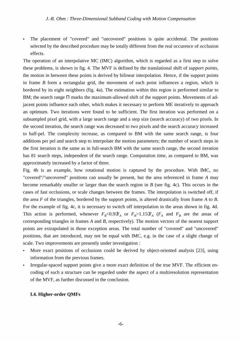
• The placement of "covered" and "uncovered" positions is quite accidental. The positions
selected by the described procedure may be totally different from the real occurence of occlusion
effects.
The operation of an interpolative MC (IMC) algorithm, which is regarded as a first step to solve
these problems, is shown in fig. 4. The MVF is defined by the translational shift of support points,
the motion in between these points is derived by bilinear interpolation. Hence, if the support points
in frame B form a rectangular grid, the movement of each point influences a region, which is
bordered by its eight neighbors (fig. 4a). The estimation within this region is performed similar to
BM; the search range Π marks the maximum-allowed shift of the support points. Movements of ad-
jacent points influence each other, which makes it necessary to perform ME iteratively to approach
an optimum. Two iterations were found to be sufficient. The first iteration was performed on a
subsampled pixel grid, with a large search range and a step size (search accuracy) of two pixels. In
the second iteration, the search range was decreased to two pixels and the search accuracy increased
to half-pel. The complexity increase, as compared to BM with the same search range, is four
additions per pel and search step to interpolate the motion parameters; the number of search steps in
the first iteration is the same as in full-search BM with the same search range, the second iteration
has 81 search steps, independent of the search range. Computation time, as compared to BM, was
approximately increased by a factor of three.
Fig. 4b is an example, how rotational motion is captured by the procedure. With IMC, no
"covered"/"uncovered" positions can usually be present, but the area referenced in frame A may
become remarkably smaller or larger than the search region in B (see fig. 4c). This occurs in the
cases of fast occlusions, or scale changes between the frames. The interpolation is switched off, if
the area F of the triangles, bordered by the support points, is altered drastically from frame A to B.
For the example of fig. 4c, it is necessary to switch off interpolation in the areas shown in fig. 4d.
This action is performed, whenever FB<0.9⋅FA or FB>1.15⋅FA (FA and FB are the areas of
corresponding triangles in frames A and B, respectively). The motion vectors of the nearest support
points are extrapolated in those exception areas. The total number of "covered" and "uncovered"
positions, that are introduced, may not be equal with IMC, e.g. in the case of a slight change of
scale. Two improvements are presently under investigation :
• More exact positions of occlusions could be derived by object-oriented analysis [23], using
information from the previous frames.
• Irregular-spaced support points give a more exact definition of the true MVF. The efficient en-
coding of such a structure can be regarded under the aspect of a multiresolution representation
of the MVF, as further discussed in the conclusion.
I.4. Higher-order QMFs
J.-R. Ohm : Three-Dimensional Subband Coding with Motion Compensation
-7-
The concept developed for 2-band split systems with 2-tap QMFs is now extended to arbitrary sym-
metric (linear phase) QMFs. Block diagrams of the complete analysis and synthesis MC-SBC filter
stages are given in figs. 5 and 6. All switches are shown in "connected" positions. Again, we regard
the polyphase realization, which performs decimation prior to analysis filtering, and interpolation
after the synthesis filter operation. Motion estimation and the "covered/uncovered" analysis must
now be applied at each frame position, while it was necessary only at each second frame in the
special case of 2-tap filters. The former A/B pairs of frames are those filtered with the center
coefficients h(R/2) and h(R/2-1) of an even-length-R symmetric filter. At these positions, the
substitution of original and DFD values remains as in (6) and (8) for the "covered/uncovered" cases.
Let h0(r)=h(r) be the even-length impulse response of the lowpass analysis filter, and the highpass
filter be defined as h1(r)=(-1)r⋅h(r). For model filters with odd-length impulse responses, add a coef-
ficient h0(R-1)=0, and set h1(0)=0, h1(r)=(-1)r-1⋅h(r-1) for the remaining coefficients to obtain even-
length filters. The model filter h(r) must have unity gain, i.e. the sum of the coefficients must be 1.
This decomposition is non-orthonormal, as in the case of the 2-tap filters. The delay, introduced
during analysis, is R/2 frames. In the "connected" case, the analysis equations are :
c m n o h x m k n l h
h x m k n l
h x m n h
h x m k n l
R R
R
R R
m n R m n R o R
m n m n o
o
m n R m n R
0 0 0
00 0
0 0
0
1 2
2
2 1 2 2
0
2 1 2 1 2 2 1
2
2 1
2 1 2
( , , ) ( ) ( , , ) ( )...
( ) ( , , )
( ) ( , , ) ( )...
( ) ( ,
( , , / ) ( , , / ) /
( , ) ( , )
( , , / ) ( , , /
/
/ /
= ⋅ + + +
+ ⋅ + ++ ⋅ +
+ ⋅ + +
− −
− −
− −
+ +
− − − +
+
− − +1 2 2) /, )o R
(15)
c m n o h x m k n l h
h x m n
h x m k n l h
h x m k n l
R R
R
R R
m n R m n R o R
o
m n m n o
m n R m n R
1 1 1
1
10 0
1
1
1 2
2
2 1 2 2
0
2 1 2 1 2 2 1
2
2 1
2 1 2
( , , ) ( ) ( , , ) ( )...
( ) ( , , )
( ) ( , , ) ( )...
( ) ( ,
( , , / ) ( , , / ) /
( , ) ( , )
( , , / ) ( , , /
/
/ /
= ⋅ + + ++ ⋅
+ ⋅ + + +
+ ⋅ + +
− −
− −
− −
+ +
− − − +
+
− − +1 2 2) /, ).o R
(16)
Again, the motion trajectory [k,l] is defined with reference to the B frame, while [k l, ] refers to A.
The motion trajectories are composed of the values [k,l]0 at the center position (which are identical
with the 2-tap case), and each R/2 values [k,l]- and [k,l]+ pointing to past and future frames, re-
spectively (see fig. 7a). A symbolic program to derive [k,l]- and [k,l]+ by "motion tracking" from the
frame-to-frame motion parameters is given as appendix B. With the synthesis filters defined as
g0(r)=h0(R-r-1) and g1(r)=h1(R-r-1), the synthesis equations are :
y m n o g c m k n l
g c m k n l
g c m k n l
g c m k
R
R
R
m n R m n R o R
m n m n o
m n R m n R o R
m n R
( , , ) ( ) ( , ) ...
( ) ( , , ) ...
( ) ( , , )
( ) (
( , , / ) ( , , / ), /
( , ) ( , )
( , , / ) ( , , / ) /
( , , /
/
2 0 0
0 00 0
0 0
1 1
1
2
1
1
2 2 2 2 4
2 3 2 3 4 1
2 1
= ⋅ + + +
+ ⋅ + + +
+ ⋅ + +
+ ⋅ +
−
−
− −
+ +
−
− − −
− − + −
− ) ( , , / ), /
( , , / ) ( , , / ) /
, ) ...
( ) ( , , ) ...
( ) ( , , )
/
n l
g c m n
g c m k n l
m n R o R
o
m n R m n R o R
R
+ ++ ⋅ −
+ ⋅ + +
−
+ +
− −
− − + −
2 1 4
2 4 2 4 4 1
1 1
1 1
2
1
(17)

J.-R. Ohm : Three-Dimensional Subband Coding with Motion Compensation
-8-
y m n o g c m k n l
g c m n
g c m k n l
g c m k n l
R
R
R
m n R m n R o R
o
m n R m n R o R
m n R m n R
( , , ) ( ) ( , ) ...
( ) ( , , ) ...
( ) ( , , )
( ) ( ,
( , , / ) ( , , / ), /
( , , / ) ( , , / ) /
( , , / ) ( , , /
/
2 1 0 0
0 0
0 0
1 1
2
2 1
0
2
2 4 2 4 4 1
2 1 2 1 4
2 3
+ = ⋅ + + ++ ⋅ +
+ ⋅ + +
+ ⋅ + +
−
−
−
− −
+ +
− −
− − − +
− − +
− 2 3 4 1
2 2 2 2 4
1 10 0
1 1
2 1
0
− − +
− − +
+
+ ⋅ + + +
+ ⋅ + +
−
+ +
), /
( , ) ( , )
( , , / ) ( , , / ) /
) ...
( ) ( , , ) ...
( ) ( , , ).
/
o R
m n m n o
m n R m n R o R
g c m k n l
g c m k n l
R
(18)
Modify indices of filters and motion parameters in steps of 2, until reaching the center coefficients,
to get the full formulation for (17) and (18). These equations are valid for filter lengths R=4,8,12,.. .
For R=6,10,14,.. : Interchange all indices of h between (17) and (18) in lines 1,3,4 and 6; let the o-
axis indices of c0 and c1 run from o-R/4+1/2 to o+R/4-1/2; replace indices of k and l by R/2-3 in
lines 1,6 and by R/2-2 in lines 3,4. Outer lines must be omitted, if the filters are as short, that indices
of coefficients or frames would coincide with those in lines 2 and 5.
The use of substituted original or DFD values must be avoided at the outer coefficient positions in
(17) and (18). This would be the case, whenever motion trajectories hit each other, or are not conti-
nued due to a detected occlusion, as it is shown in fig. 7b (in the [k,l]+ and [k,l]- parts of the motion
trajectories this indicates the presence of "covered" and "uncovered" pixels, respectively). A disrup-
ted motion trajectory can be handled by a constant-value-extension method, which is a usual choice
for subband analysis/synthesis of finite length signals [24]. All coefficients remaining at the tail of
the filter are multiplied with the value of the pixel situated at the last valid position within the
motion trajectory. The total delay after synthesis is R frames.
5. Spatial interpolation for subpel-accurate MC
When subpel-accurate MC is applied, spatial interpolation operations are necessary to estimate
signal values between known samples, according to (5)-(13), (15)-(18). The L image is generated
after spatial interpolation in frame A, while spatial interpolation in frame B must be performed to
generate the H image. During synthesis, the H image must be interpolated to reconstruct frame B,
while L image interpolation is necessary to reconstruct frame A. With higher-order QMFs, more
interpolations are necessary at the positions of all outer coefficients. MC-SBC with subpel accuracy
allows no perfect-reconstruction synthesis.
Bilinear interpolation is a widely used scheme for subpel value estimation. Unfortunately, the
equivalent 1-D filter for the bilinear interpolator, e.g. applied to half-pel positions, is a strong
lowpass with transition frequency (3 dB attenuation) at Ω=π/2. If the interpolation filter has such a
smooth frequency roll-off, the result after reconstruction appears heavily blurred.
One approach to obtain subpel values with higher accuracy is the fast algorithm for cubic spline in-
terpolation [25], which has a complexity of 4 multiplications/pixel-to-be-interpolated per spatial di-
mension. Applied over 4 cascaded analysis/synthesis stages, a slight blurring effect remains visible,

J.-R. Ohm : Three-Dimensional Subband Coding with Motion Compensation
-9-
but the quality is sufficient at low data rates. Better interpolation results were obtained by parallel
(blockwise) interpolation in the DCT frequency domain, as shown in fig. 8. After blockwise trans-
form, zero values are appended to the DCT spectrum (fig. 8a), then a quadruple-sized IDCT is
applied. The positions of the interpolated pixels, resulting after IDCT, are apart from the former ori-
ginal values (fig. 8b). To obtain estimates at any subpel position, bilinear interpolation is still neces-
sary. This interpolation is performed in an upsampled image, and effects no heavy degradation of
the higher frequencies. The block size of the DCT should be large, because values at the block
borders are inaccurate - the interpolation blocks must overlap (fig. 8c). It was found that a DCT
block size of 32x32, and an overlap of 3 pixels, are sufficient for satisfactory reconstruction results.
Differences between the original sequence and the reconstruction over 4 analysis/synthesis stages
are hardly visible (some ringing effects may appear, when fields instead of frames are interpolated,
but these are not visible in the motion video presentation). For the highly-detailed sequence
MOBILE&CALENDAR, the reconstruction PSNR is more than 37 dB; other sequences showed PSNR
values of 40-45 dB.
I.6. Cascade structures
To obtain multi-band frequency decompositions, the 2-band analysis and synthesis stages must be
arranged as cascade structures. An example is the octave-band structure shown in fig. 9. For opti-
mum energy packing in the subband signals, it is necessary to optimize the motion parameters at
each stage of the cascade. The results of motion analysis from one lower cascade stage are used as a
starting-point for estimation at the next-higher stage. Even with the 2-tap filters, where ME is per-
formed only at each second frame position, a simple addition of the local motion parameters from
two adjacent A-B frame pairs was sufficient to obtain the initial estimate for the next-higher stage.
This reduces the overall complexity, because the search range Π can be kept small at all stages.
The result of motion-compensated temporal subband decomposition undergoes a 2-D spatial
decomposition. To compare the efficiency of different motion-compensated and uncompensated
temporal axis decompositions, it is necessary to have regard to the spectral flatness of the resulting
3-D signals. This is taken into account by the coding gain, which is defined as the ratio of arithmetic
mean to geometric mean values from the quadratic expectation values of the resulting frequency
components [26].
The octave-band decomposition example in fig. 9 results in a 16:1 decimation of the lowest fre-
quency band. Two more decomposition schemes were compared to that, which result in the same
bandwidth of the LLLL band. These are a full-band decomposition with constant-width subbands
and an 8-band modified octave-band structure, where the first H band was split again in an octave-
like fashion. The resulting frequency band partitions for all three schemes are shown in fig. 10.
Coding gains of 3-D coding over 2-D intraframe coding are given in tab.1; for spatial
decomposition, the TDAC scheme described in section II.2 was employed. The values were

J.-R. Ohm : Three-Dimensional Subband Coding with Motion Compensation
-10-
calculated from the 25 Hz video sequences MOBILE&CALENDAR, FLOWER GARDEN and TABLE
TENNIS; two sampling formats were compared, each for the cases without and with MC (the latter
with full-pel and half-pel accurate BM) :
• Interlaced (CCIR 601, 720x576 pixels); in this case, the odd fields are the A-, the even fields the
B-frames fed into the first stage of the cascade.
• Progressive (SIF, 352x288 pixels), which were generated by rowwise subsampling of the odd
fields from the CCIR 601 sequences.
The coding gain clearly increases with a higher number of subbands for the full-band
decomposition. The gain achievable by half-pel accuracy is higher by around 2 dB for progressive
and 2.5 dB for interlaced sequences, as compared to full-pel accuracy. With MC, the coding gain in
the cases of octave-band (for progressive sequences) and modified octave-band (for interlaced
sequences) decompositions, is almost as good as for the full 16-band decomposition. The efficiency
of the octave-type structures is important, because less motion parameters have to be calculated and
transmitted as side information, than with full-band decomposition. With the 2-tap filters, the
octave-band structure equals the Haar wavelet transform, while the full-band structure is equivalent
to the Hadamard transform (both except for a scale factor, and only in the "connected" areas). The
modified-octave structure may be viewed under the theory of wavelet packets [28].
In the "interlaced" case, the H band contains high energy, if the octave-band structure is employed,
which is due to the spatio-temporal shift between adjacent fields. With the modified-octave
structure, the information about the brightness of both even and odd fields is concentrated in LLLL,
the information about their differences in HLLL.
Fig. 11 shows examples of image fields, resulting after temporal modified-octave decomposition of
the interlaced MOBILE&CALENDAR sequence. In the case without MC (fig. 11a), the LLLL image
appears heavily blurred, while the HH image still contains a high amount of information. This is no
longer the case when MC is applied. The spatial information in the lowest-frequency temporal band
LLLL is sharp, and can be regarded as a mean value extract from a number of adjacent frames.
Furthermore, it is interesting to note the differences between BM (fig. 11b), and interpolative MC
(fig. 11c). In the BM case, blocking effects appear in the LLLL image, which can be expected to
cause degradations at higher compression ratios.
Experiments with higher-order QMFs were performed, using Johnston's filters 8A and 16C [29].
The 8-tap filter was modified to unity gain. The longer filters were applied up to the second stage of
the cascade, in order to keep a reasonable encoding delay. The coding gains over the 2-tap filters
were 0.04/0.11 dB with BM motion compensation and 0.07/0.13 dB with IMC, for the 8-tap/16-tap
filters, respectively. These relatively low coding gains indicate the high correlation along the motion
trajectory. It can be concluded, that the application of longer filters is not reasonable at high rates,
where the coding gain is a measure to determine the rate-distortion efficiency [26]. At low rates, the
longer filters were found to eliminate jerky, artificial movements, which are temporal-axis blocking
effects, appearing with the 2-tap filters. Unfortunately, the number of motion parameters to be

J.-R. Ohm : Three-Dimensional Subband Coding with Motion Compensation
-11-
calculated and transmitted is doubled, when longer filters are used. It is suggested that a new stra-
tegy of motion representation, including spatio-temporal interpolation of the MVF, is needed
instead of the lossless frame-to-frame parameter encoding concept, to gain full advantage of longer
QMFs.
II. Encoding of the temporal-axis subband signals
II.1. Comparison with MC prediction coding
The basic decomposition structure of the MC-SBC scheme is shown in fig. 12 for the 2-tap filter
case. With the non-orthonormal filters, the resulting L image is the motion-compensated average,
while the H image is half of the DFD between frames A and B. If the quantizer step size chosen at
the original image level is Q, the optimum step sizes to encode the L and H images must be Q / 2 ,
to achieve the same MSE (this is just the factor distinguishing the filters as used from orthonormal
ones). MC prediction coders would perform intraframe coding of A, and DFD encoding of B, both
with step size Q. It follows that, with MC-SBC, the DFD signal (H frame) must be encoded by a
factor of 2 2/ less accurate than in MC prediction. As a counterpart, the L frame carries mean
value information about both frames A and B, and must be encoded by the same factor more
accurate than the original (intra-coded) frame. With the R=1/2 log2(σ2/D) formula from rate-
distortion theory [26], we would come to the conclusion that no coding gain over MC prediction is
possible by the application of MC-SBC with 2-tap filters. This effect remains constant with the
number of cascaded stages; for example, the four-stage configuration of fig. 9 would result in no
coding gain, as compared to MC prediction with a frame refresh at each 16th frame. Indeed, two
important differences must be stated :
• The requirement for a more exact quantization of L indicates, that energy compaction
(concentration of information to the lowest-frequency band) is higher in MC-SBC. This effect
increases with the number of cascaded stages. It is well-known, that schemes with higher energy
compaction are superior for encoding at low data rates; e.g. transform coding of still images
clearly outperforms DPCM at rates below 1 bit/pixel.
• In MC-SBC, the DFD signal is calculated between original frames A and B, in MC prediction
between a reconstructed A and an original B. This means that coding error feedback (which de-
teriorates the efficiency of MC prediction at low rates) does not occur.
Both effects have their counterparts in a more efficient transmission over lossy channels. The higher
energy compaction allows an efficient protection of information, while the non-recursive structure
inhibits propagation of transmission errors [19].
Of course, these statements are only true for the "connected" parts of the decomposition. For
"uncovered" pixels (which are original values from B), the optimum step size is Q, while for the

J.-R. Ohm : Three-Dimensional Subband Coding with Motion Compensation
-12-
DFD values at "covered" positions (which carry the whole information about A), the optimum step
size is Q/2. Hence, the performance at these positions would be the same as with a MC prediction
coder, which would apply intraframe-encoding at the uncovered parts of an image.
It follows that the optimum quantizer step sizes differ between the "connected", "covered" and
"uncovered" positions. The step sizes at position (m,n) can be calculated for the L and H frames at
any cascade stage (where qA, qB are the outputs from the next lower stage, set qA=qB=Q for the first
stage) :
"connected" :q m nq m k n l q m n
q m k n l q m nL
A B
A B
m n m n
m n m n( , )
( , ) ( , )
( , ) ( , )
( , ) ( , )
( , ) ( , )=
+ + ⋅+ + +2 2
(19)
"uncovered" :q m n q m nL B( , ) ( , )= (20)
"connected" :q m nq m n q m k n l
q m n q m k n lH
A B
A B
m n m n
m n m n( , )
( , ) ( , )
( , ) ( , )
( , ) ( , )
( , ) ( , )=
⋅ + +
+ + +2 2(21)
"covered" : q m n q m nH B( , ) . ( , )= ⋅0 5 . (22)
An algorithmically simpler form for the "connected" cases is to proceed with 1/qL(H)2=1/qA
2+1/qB2
from stage to stage.
II.2. Spatial decomposition of the temporal-axis subbands
The 2-D images (L.. and H..), resulting after motion-compensated temporal-axis subband decom-
position, exhibit spatial correlation. Generally, any 2-D image compression scheme like DCT, SBC,
VQ or fractal coding might be employed. E.g., earlier experiments were performed, combining MC-
SBC with a 2-D DCT [18]. Indeed, better coding results than with DCT were obtained by the appli-
cation of a time-domain aliasing cancellation (TDAC) subband decomposition scheme [30], a
parallel filterbank approach resulting in U⋅V subbands. A fast algorithm for 2-D TDAC is based on
a 2-D DCT of size 2U⋅2V [31]; U=V=8 was chosen in the experiments, resulting in 64 spatial
subbands of constant bandwidth. In fact, TDAC is very similar to the lapped orthogonal transform
(LOT) approach, proposed more recently for image coding applications [32]; both belong to the
class of cosine-modulated filterbanks.
It is now described, how the requirement for spatial-variable quantizer functions q(m,n) from (19)-
(22) can be fulfilled. The subband transform "weighs" the local quantizer functions by the absolute
values of the impulse responses hu,v(p,q) (size P⋅Q subband analysis filters), which are used to
calculate the spatial subband coefficients cu,v(i,j) ; i=m/U, j=n/V are the coordinate positions in the
subband domain. The optimum quantizer step sizes for these coefficients in the case of orthonormal
decompositions then are
q i j q h p qu vq
Q
p
P
u vi U p P j V q Q, ,( , ) ( ) ( , )/ , /= ⋅⋅ − + ⋅ − +=
−
=
−
∑∑ 2
0
1
0
122 2 . (23)
(23) can be realized via a fast transform algorithm in the case of TDAC decomposition.

J.-R. Ohm : Three-Dimensional Subband Coding with Motion Compensation
-13-
II.3. Encoding of the spatio-temporal subband signals
To approach the entropy rate of the spatio-temporal subband decomposition, the adaptive lattice VQ
(ALVQ) scheme shown in fig. 13 was employed. This scheme was described in more detail in [19];
in a MC prediction coder, a slightly lower rate was achieved than with the VLC of MPEG. The
scheme adapts well to the varying statistics of the spatio-temporal subbands
For the lowest-frequency temporal subband, spatially-weighted quantization was applied; for this
purpose, MPEG's intra_quantizer_matrix was used [1]. The remaining temporal-subband quantizers
were designed with a deadzone, which is 3/2 of the usual quantizer stepsize.
In ALVQ, samples only from the same spatio-temporal subband are arranged to a vector. The adap-
tive components are run-length coding (RLC) and codebook-size adaptation. Two stages of RLC are
used : Block-RLC indicates the positions (i,j), where any subband coefficients cu,v(i,j) have to be
quantized; sample-RLC points to the positions of these coefficients inside the block. Block-RLC si-
gnificantly lowers the rate for the high-frequency temporal subbands, where often only few samples
have to be transmitted. The lattice E8 was employed for rates above 2 bits/sample, Λ16 for the lower
rates, as requested by the codebook size adaptation. All adaptation parameters, and the codebook
index vectors, resulting from the procedure described in [33], are encoded by simple Huffman
VLCs.
II.4. Encoding of the motion parameters
The octave-band cascade structure of MC-SBC results in a sort of pyramid representation of motion
parameters; the higher stages exhibit motion, which is present over several frames, while the lowest
stage represents the frame-to-frame motion. This fact was used to reduce the search range, as
described in section I.6. The redundancy in the spatio-temporal MVF can as well be exploited for
encoding of the motion parameters. Motion parameters were encoded differentially, proceeding
from the bottom of the decomposition cascade to the top : The initial estimate of ME is subtracted
from the actual value. Additionally, a spatial prediction from the next lefthand and topmost
parameter positions is performed (parameters are the block shifts in BM and support point shifts in
IMC). To encode the parameter differences, MPEG's VLC table was applied. Rate saving, as
compared to pure spatial prediction at each cascade stage, is 5-10 %.
II.5. Results
The following coding examples were performed on color (YUV) sequences; ME was performed
with the luminance component Y, and the motion parameters were divided by half, according to the
J.-R. Ohm : Three-Dimensional Subband Coding with Motion Compensation
-14-
subsampling factors of color components U and V. Besides, spatio-temporal decomposition and
quantization strategies were the same for Y, U and V.
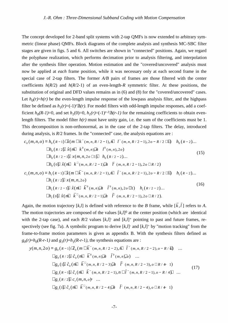
To evaluate the performance of the 3-D MC-SBC coder, it was compared to a MC prediction coder
and to 3-D SBC without MC. Fig. 14 shows the PSNR results obtained with the CCIR 601 inter-
laced MOBILE&CALENDAR sequence (the given PSNR is averaged over luminance and chrominance
components, and over all frames). All coders used the same scheme for spatial encoding (TDAC
with AVLC). MC-SBC was performed with BM and IMC. MC-SBC/BM and MC prediction were
with half-pel accuracy. MC prediction was performed with a field/frame adaptative BM, and
without frame refresh. In BM, the size of search blocks was 16x16, the support points in IMC were
also on a grid with 16-pixel spaces.
The hybrid coder lags behind by approximately 4 dB at 2 Mbit/s and comes closer at higher data
rates; this behaviour is as expected from the statements in section II.1. The gain of MC-SBC over
SBC without MC remains almost constant at around 4 dB, over a wide range of data rates. MC-
SBC/IMC outperforms MC-SBC/BM, especially at low rates.
To further enhance the coding efficiency, it was found convenient to perform MC prediction of the
LLLL images. In the case of a scene change, the cascade decomposition must be interrupted.
Remaining lowpass images at any cascade stages are then also encoded with MC prediction from
their predecessors. Low bit rate coding results for different sequences are illustrated in fig. 15, the
rates for the different components are given in tab.2. In the MOBILE&CALENDAR example, MC
prediction of the LLLL fields was applied, but with a frame refresh at each 16th frame; the reader
may compare this to the results of a MPEG coder, GOF length of 16. The examples with SIF
sequences (FLOWER GARDEN and TABLE TENNIS) are without frame refresh over the whole
sequence, except for the scene changes in TABLE TENNIS. For TABLE TENNIS, the rates for the first
part with a zoom, which consumes most bit rate, are given in brackets. The rates for the higher-
frequency temporal subbands and motion parameters increase drastically, due to the faster changes.
All these examples exhibit compression ratios between 150:1 and 200:1 for full-motion sequences !
III. Conclusions
This paper has described new strategies to apply motion-compensated subband analysis along the
temporal axis of video sequences. The technique can easily be extended to a variety of schemes
based on 2-band splits, including wavelet approaches [27]. The result is a motion-compensated, spa-
tio-temporal multiresolution representation of the video signal, which depends on a component of
motion information. It is a widespread opinion in the image coding community, that frame skipping
is sufficient to obtain a multiresolution representation along the temporal axis of video signals; it is
argued, that the 3-D signal is composed from a pure 2-D image signal and a displacement field [34].

J.-R. Ohm : Three-Dimensional Subband Coding with Motion Compensation
-15-
The author does not agree with this point of view. The occurence of occlusions produces new parts
of image information. This effect must not be neglected, if we regard the levels of temporal hierar-
chy. The motion-compensated 3-D spectrum concentrates as much information as possible at the
lowest temporal frequency, if MC is perfect. The MC-SBC scheme can be viewn as a realization of
a short-time spectral analysis, which adapts to the occurence and quickness of occlusions. The
motion-compensated subband analysis is performed with a finer temporal resolution (subband
analysis is switched off, performing the mentioned substitutions), whenever image information
vanishes or new areas appear. An effect of this property is visible only in a moving video
presentation : The foreground tree of FLOWER GARDEN in fig. 15b moves very fast. Here, the
covered/uncovered areas are updated at each frame, even at this low data rate. The tree right in front
of the house also covers and uncovers small parts of the house with each frame, but this leads to a
relatively small energy in the highpass bands. Updating occurs less frequently, which results in a
slight "gummy" movement of tree and background. Viewers note, that this is a very cute and
thoroughly acceptable effect. It is surely less serious than the jerk of whole images, which occured
with frame skipping, and is unacceptable for full-motion video.
MC-SBC can perform spatio-temporally scalable encoding of video sequences, which may allow a
unique hierarchical representation, from very low resolution at low bit rates up to a high-quality
level. In this context, the non-recursive decoder structure is advantageous, one heavy obstruction of
hybrid coders is put aside. Up to now, the spatio-temporal multiresolution property has only been
realized for the part of the 3-D image information. The MC-SBC scheme still needs a spatio-tem-
porally hierarchical, or scalable, representation of the motion information. At the present state, loss-
less encoding of the motion information, as used during analysis, is always recommended for
subband synthesis. To solve this problem, the interactions between image information and motion
information have to be further investigated. Spatio-temporal interpolation of motion parameters is
regarded as a convenient way, which would open the path to use higher-order subband filters, with
better aliasing cancellation properties. An approach in this direction will be presented in a
forthcoming paper [35].
For further improvements, many ways can be thought of. The interactions of the subband filters,
used for temporal and spatial decomposition, must be carefully examined, especially from the
viewpoint of wavelet theory. With proper choice of spatial filters, the spatial interpolation for
subpel-accurate MC might also be integrated into the 3-D subband decomposition. This would
replace the DCT interpolation, which seems to be unnatural for the scheme. MC can be enhanced by
use of object-oriented techniques, which may not only regard the information from the previous
image frame (as predictive object-oriented coders usually do), but from the higher levels of the
temporal-axis subband decomposition as well. Weighted quantization with regard to the spatio-
temporal response of the human visual system could be applied. Combinations with nonlinear
encoding techniques, like fractal coding for the image information in the temporal lowpass band,
can also be suggested. The MC-SBC scheme can not only be combined with most techniques

J.-R. Ohm : Three-Dimensional Subband Coding with Motion Compensation
-16-
investigated today to enhance hybrid coders, but may also give rise to further development of new
approaches like multiframe motion compensation, which could more efficiently exploit the
temporal-axis correlation in video sequences.
Appendix
A : Example program in a C-like notation for derivation of motion parameters [k l, ] from [k,l]. The
array arr_/k,l/ must be calculated in advance and may define UNCOVered positions, if allowed so
by the ME procedure; additonal conditions for UNCOVerings are stated in the program. The arrays
contain the horizontal and vertical displacement components k and l, which also may be used
separately as arr_/k/, arr_/l/. OUT_FR defines a displacement reference outside the frame size; ni []
denotes the nearest-integer function.
arr_/k,l/ [ number_of_rows , number_of_columns ] /* MVF B→A */
arr_/ , /k l [ number_of_rows , number_of_columns ]=COVER /* define COVERed in advance */
for n=0, n<number_of_rows, n++ ; for m=0, m<number_of_columns, m++
if [ arr_/k,l/ [n,m] != UNCOV ]
if [ [ n+ni[arr_/l/ [n,m]] , m+ni[arr_/k/ [n,m]] ] == OUT_FR ] arr_/k,l/ [n,m] = UNCOV
elif [ arr_/ , /k l [ n+ni[arr_/l/[n,m]], m+ni [arr_/k/[n,m]] ] != COVER ] arr_/k,l/[n,m] =
UNCOV
else arr_/ , /k l [ n+arr_/l/ [n,m] , m+arr_/k/ [n,m] ] = - arr_/k,l/ [n,m]
All positions remaining COVERed in arr_/ , /k l have no references in frame B.
J.-R. Ohm : Three-Dimensional Subband Coding with Motion Compensation
-17-
B : Example program in a C-like notation for derivation of motion trajectory parameters [k,l]+, [k,l]-
, [k l, ]+ and [k l, ]-. The array arr_/k,l/ must be calculated in advance for R/2 past frames, arr_/k l, /
for R/2 future frames (for analysis, or synthesis with filter length R=6,10,14,.. only for R/2-1
frames). The first may contain UNCOVered, the latter COVERed positions, as defined in appendix
A. The motion trajectories are derived for position (m,n) of the A and B frames; [k,l]0 and [k l, ]0
denote the motion vectors at this position between A and B.
arr_/k,l/ [ R/2 , number_of_rows , number_of_columns ] /* MVFs of R/2 past frames */
arr_/ , /k l [ R/2 , number_of_rows , number_of_columns ] /* MVFs of R/2 future frames */
arr_/k,l/+ [R/2] ; arr_/ , /k l + [R/2] ; arr_/k,l/- [R/2] ; arr_/ , /k l - [R/2]
val_/k,l/+=[0,0] ; val_/k,l/-=[k,l]0 ; val_/ , /k l +=[k l, ]0 ; val_/ , /k l -=[0,0]
for r=0,r<R/2, r++
if [ arr_/k,l/ [ r, n+ni[val_/l/-] , m+ni[val_/k/-] ] != UNCOV && val_/k,l/- != UNCOV ]
val_/k/- = val_/k/- + arr_/k/ [ r , n+ni[val_/l/-] , m+ni[val_/k/-] ] ; arr_/k/- [r] = val_/k/-
val_/l/- = val_/l/- + arr_/l/ [ r , n+ni[val_/l/-] , m+ni[val_/k/-] ] ; arr_/l/- [r] = val_/l/-
else arr_/k,l/- [r] = UNCOV ; val_/k,l/- = UNCOV
if [ arr_/k,l/ [ r , n+ni[val_/l /-] , m+ni[val_/k /-] ] != UNCOV && val_ / , /k l - != UNCOV ]
val_/k /- = val_/k /- + arr_/k/ [ r , n+ni[val_/l /-] , m+ni[val_/k /-] ] ; arr_/k /- [r] = val_/k /-
val_/l /- = val_/l /- + arr_/l/ [ r , n+ni[val_/l /-] , m+ni[val_/k /-] ] ; arr_/l /- [r] = val_/l /-
else arr_/ , /k l - [r] = UNCOV ; val_/ , /k l - = UNCOV
if [ arr_/ , /k l [ r , n+ni[val_/l/+] , m+ni[val_/k/+] ] != COVER && val_/k,l/+ != COVER ]
val_/k/+ = val_/k/+ + arr_/k / [ r , n+ni[val_/l/+] , m+ni[val_/k/+ ] ] ; arr_/k/+ [r] = val_/k/+
val_/l/+ = val_/l/+ + arr_/l / [ r , n+ni[val_/l/+] , m+ni[val_/k/+] ] ; arr_/l/+ [r] = val_/l/+
else arr_/k,l/+ [r] = COVER ; val_/k,l/+ = COVER
if [ arr_/ , /k l [ r , n+ni[val_/l /+] , m+ni[val_/k /+] ] != COVER && val_/ , /k l + != COVER ]
val_/k /+ = val_/k /+ + arr_/k / [ r , n+ni[val_/l /+] , m+ni[val_/k /+] ] ; arr_/k /+ [r] = val_/k /+
val_/l /+ = val_/l /+ + arr_/l / [ r , n+ni[val_/l /+] , m+ni[val_/k /+] ] ; arr_/l /+ [r] = val_/l /+
else arr_/ , /k l + [r] = COVER ; val_/ , /k l + = COVER
The filter paths are broken (constant value extension as described in section I.4) at the COVERed
and UNCOVered positions in arr_/k,l/+, arr_/ , /k l +, arr_/k,l/-, arr_/ , /k l -

J.-R. Ohm : Three-Dimensional Subband Coding with Motion Compensation
-18-
References
[1] ISO-IEC/JTC1 SC 29/WG 11 (MPEG) : "Coding of moving pictures and associated audio for
digital storage media at up to about 1.5 Mbit/s," ISO Rec. 11172, Part 2: Video.
[2] P. H. Westerink, J. Biemond and F. Muller : "Subband coding of image sequences at low bit
rates," Signal Processing : Image Commun. 2 (1990), pp. 441-448.
[3] M. Pecot, P. Tourtier and Y. Thomas : "Compatible Motion Compensated Subband Coding,"
in Proc. PCS-91, pp. 7.6-1 - 7.6-3., Sept. 1991.
[4] Y.-Q. Zhang and S. Zafar : "Motion-compensated wavelet transform coding for color video
compression," IEEE Trans. Circ. Syst. Video Techn., vol. CSVT-2, pp. 285-296, Sept. 1992.
[5] J. W. Woods (ed.) : "Subband image coding," Boston, MA : Kluwer, 1991.
[6] G. Karlsson and M. Vetterli : "Sub-band coding of video signals for packet switched net-
works," SPIE Visual Commun. Image Processing, vol. 845 pp. 446-456, 1987.
[7] F. Bosveld, R. L. Lagendijk and J. Biemond : "Hierarchical video coding using a spatio-tempo-
ral subband decomposition," in Proc. ICASSP-92, vol.3, pp. III/221-III/224, Mar. 1992.
[8] A. Jacquin and C. Podilchuk : "Very low bit rate 3D subband-based video coding with a
dynamic bit allocation," in SPIE Proc. Internat. Symp. Video Commun. and Fiber Optic
Services, vol. 1977, pp. 156-167, Apr. 1993.
[9] C. I. Podilchuk, N. S. Jayant and P. Noll : "Sparse codebooks for the quantization of non-
dominant sub-bands in image coding," in Proc. ICASSP-90, vol. 4, pp. 2101-2104, Apr. 1990.
[10] C. I. Podilchuk and N. Farvardin : "Perceptually based low bit rate video coding," in Proc.
ICASSP-91, vol. 4, pp. 2837-2840, May 1991.
[11] C. Podilchuk and A. Jacquin : "Subband video coding with a dynamic bit allocation and
geometric vector quantization," in SPIE Proc. IS&T Symp. Electr. Imaging and Tech., vol.
1668, pp. 241-252, Feb. 1992.
[12] G. Schamel : "Motion adaptive four channel HDTV subband/DCT coding," in Proc. PCS-90,
pp. 1.7-1 - 1.7-3, Mar. 1990.
[13] M. P. Queluz : "A 3-dimensional subband coding scheme with motion-adaptive subband se-
lection," in Proc. EUSIPCO-92, pp. 1263-1266, Sept. 1992.
[14] T. Akiyama, T. Takahashi and K. Takahashi : "Adaptive three-dimensional transform coding
for moving pictures," in Proc. PCS-90, pp.8.2-1 - 8.2-2, Mar. 1990.
[15] W. Li and M. Kunt : "Video coding using 3D subband decompositions," presented at PCS-93
(Proc. PCS-93, pp. 11.1-1 - 11.1-2, do not fully reflect the oral presentation), Mar. 1993.
[16] T. Kronander : "Some aspects of perception based image coding," PhD Dissertation, Linköping
Univ., 1989.
[17] : "New results on 3-dimensional motion compensated subband coding," in Proc. PCS-90,
p.8.5-1, Mar. 1990.
J.-R. Ohm : Three-Dimensional Subband Coding with Motion Compensation
-19-
[18] J.-R. Ohm : "Temporal domain sub-band video coding with motion compensation," in Proc.
ICASSP-92, vol.3, pp. III/229-III/232, Mar. 1992.
[19] : "Advanced packet video coding based on layered VQ and SBC techniques," IEEE
Trans. Circ. Syst. Video Techn., vol. CSVT-3, pp. 208-221, June 1993.
[20] : "Three-dimensional motion-compensated subband coding," in SPIE Proc. Internat.
Symp. Video Commun. and Fiber Optic Services, vol. 1977, pp. 188-197, Apr. 1993.
[21] M. Nicoulin, M. Mattavelli, W. Li, A. Basso, A. C. Popat and M. Kunt : "Image sequence co-
ding using motion compensated subband decomposition," in : Motion Analysis and Image
Sequence Processing, M. I. Sezan and R. L. Lagendijk (eds.), pp. 225-256, Boston, MA :
Kluwer, 1993.
[22] M. Bierling : "Displacement estimation by hierarchical blockmatching," SPIE Visual Commun.
Image Processing, vol. 1001, pp. 942-951, 1988.
[23] H. G. Musmann, M. Hötter and J. Ostermann : "Object-oriented analysis-synthesis coding of
moving images," Signal Processing : Image Commun., vol. 1, no.2, 1991.
[24] G. Karlsson and M. Vetterli : "Extension of finite length signals for sub-band coding," Signal
Processing 17 (1989), pp. 161-168, June 1989.
[25] M. Unser, A. Aldroubi and M. Eden : "Fast B-spline transforms for continous image represen-
tation and interpolation," IEEE Trans. Patt. Anal. Mach. Intell., vol. PAMI-13, pp. 277-285,
Mar. 1991.
[26] N. S. Jayant and P. Noll : "Digital coding of waveforms," Englewood Cliffs, NJ : Prentice-
Hall, 1984.
[27] O. Rioul and M. Vetterli : "Wavelets and signal processing," IEEE Signal Processing Mag.,
Oct. 1991
[28] K. Ramchandran and M. Vetterli : "Best wavelet packet bases in a rate-distortion sense," IEEE
Trans. Image Processing, vol. IP-2, pp. 160-175, Apr. 1993.
[29] J. D. Johnston : "A filter family designed for use in quadrature mirror filter banks," in Proc.
ICASSP-1980, pp. 291-294, May 1980.
[30] J. P. Princen and A. B. Bradley : "Analysis/synthesis filter bank design based on time domain
aliasing cancellation," IEEE Trans. Acoust., Speech, Signal Processing, vol. ASSP-34, pp.
1153-1161, Oct. 1986.
[31] G. Schuller : "Untersuchung von Kurzzeitspektralanalysatoren mit Spiegelfehlerkompensation-
seigenschaften," Diplomarbeit (Masters thesis, in German), Techn. Univ. Berlin, Berlin 1989.
[32] H. S. Malvar and D. H. Staelin : "The LOT : transform coding without blocking effects," IEEE
Trans. Acoust., Speech, Signal Processing, vol. ASSP-37, pp. 553-559, Apr. 1989.
[33] J. H. Conway and N. J. A. Sloane : "Fast quantizing and decoding algorithms for lattice quanti-
zers and codes," IEEE Trans. Inform. Theory, vol. IT-28, pp. 227-232, Mar. 1982.

J.-R. Ohm : Three-Dimensional Subband Coding with Motion Compensation
-20-
[34] K. M. Uz, M. Vetterli and D. LeGall : "Interpolative multiresolution coding of advanced tele-
vision with compatible subchannels," IEEE Trans. Circ. Syst. Video Techn., vol. CSVT-1, pp.
86-99, Mar. 1991.
[35] J.-R. Ohm : "Motion-compensated 3-D subband coding with multiresolution representation of
motion parameters," submitted to the First IEEE Internat. Conf. on Image Proc., Nov. 1994.

J.-R. Ohm : Three-Dimensional Subband Coding with Motion Compensation
-21-
Biography
Jens-Rainer Ohm (M '92) received the Dipl.-Ing. and Dr.-Ing degrees in Electrical Engineering
from the Technische Universität Berlin (TUB) in 1985 and 1990, respectively. From 1985 to 1990,
he was as a teaching assistant with the Institut für Fernmeldetechnik of TUB, performing research
work on still image vector quantization. Since 1990, he has been involved in a research project con-
cerning advanced techniques for ATM video coding. His general interests include the fields of
signal and image processing, communication systems and information theory. Dr. Ohm is teaching a
course on digital image coding and transmission.

J.-R. Ohm : Three-Dimensional Subband Coding with Motion Compensation
-22-
List of figures
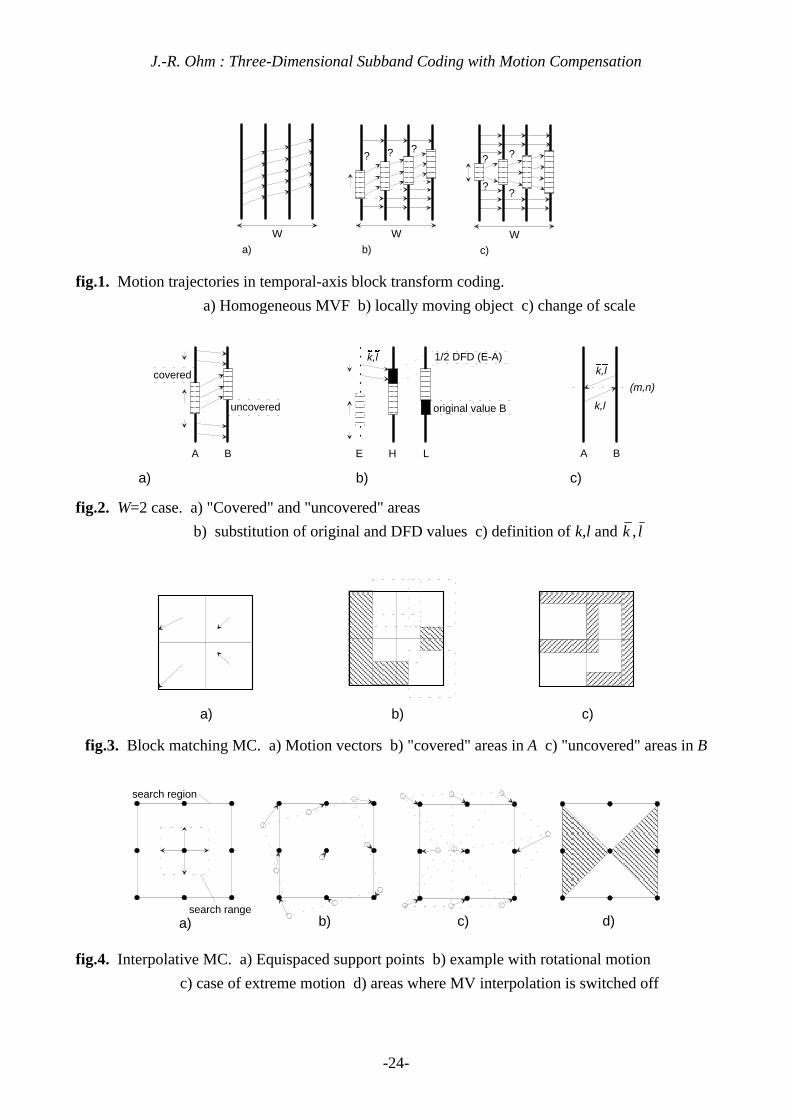
fig.1. Motion trajectories in temporal-axis block transform coding.
a) Homogeneous MVF b) locally moving object c) change of scale
fig.2. W=2 case. a) "Covered" and "uncovered" areas
b) substitution of original and DFD values c) definition of k,l and k l,
fig.3. Block matching MC. a) Motion vectors b) "covered" areas in A c) "uncovered" areas in B
fig.4. Interpolative MC. a) Equispaced support points b) example with rotational motion
c) case of extreme motion d) areas where MV interpolation is switched off
fig.5. MC-SBC analysis stage, polyphase structure with arbitrary-length QMFs.
fig.6. MC-SBC synthesis stage, polyphase structure with arbitrary-length QMFs.
fig.7. a) Motion trajectories for higher-order QMFs b) "uncovered"/"covered" areas in k-/k+
fig.8. Interpolation in the DCT frequency domain.
a) DCT/IDCT blocks b) positions of original and interpolated values c) block overlap
fig.9. Octave-band cascade structure.
fig.10. Frequency bandwidths in different cascade decompositions.
a) Octave-band b) modified octave-band c) full-band
fig.11. Subband image examples after temporal modified-octave decomposition, sequence
MOBILE&CALENDAR, interlaced; subbands LLLL and HH are shown.
a) Without MC b) block matching MC c) interpolative MC
fig.12. Basic decomposition structure with 2-tap filters and optimum quantizer stepsizes.
fig.13. Adaptive lattice vector quantization (ALVQ).
fig.14. PSNR results, MOBILE&CALENDAR, different interframe coders
(MC prediction, MC-SBC, SBC without MC).
fig.15. Original frames and MC-SBC/IMC coding examples.
a) MOBILE&CALENDAR, CCIR 601, 1.1 Mbit/s b) FLOWER GARDEN, SIF, 156 kbit/s
c) TABLE TENNIS, SIF, 159 kbit/s

J.-R. Ohm : Three-Dimensional Subband Coding with Motion Compensation
-23-
List of tables
tab.1. Coding gains with different cascade decomposition structures, full-pel and half-pel MC
accuracy.
tab.2. Parameters of low-rate coding examples from fig. 15.
(values for the first part of TABLE TENNIS - with zoom - are given in brackets)
J.-R. Ohm : Three-Dimensional Subband Coding with Motion Compensation
-24-
??
a) b)
?
W W
??
c)
W
??
fig.1. Motion trajectories in temporal-axis block transform coding.
a) Homogeneous MVF b) locally moving object c) change of scale
covered
uncovered
1/2 DFD (E-A)
original value B
a) b)
A B H LE
c)
A B
k,l
(m,n)
k,l
k,l
fig.2. W=2 case. a) "Covered" and "uncovered" areas
b) substitution of original and DFD values c) definition of k,l and k l,
a) b) c)
fig.3. Block matching MC. a) Motion vectors b) "covered" areas in A c) "uncovered" areas in B
a) b) c)
search region
search ranged)
fig.4. Interpolative MC. a) Equispaced support points b) example with rotational motion
c) case of extreme motion d) areas where MV interpolation is switched off

J.-R. Ohm : Three-Dimensional Subband Coding with Motion Compensation
-25-
I
L
H
M
+-
T = R/2 - 1
Motionestimation
PolyphaseMC-QMF (L)
Motion trajectorycalculation
"covered"/"uncovered" analysis
MC
:2
Σ
"unc
over
ed"
"cov
ered
"
z-T
z-T
z-1
PolyphaseMC-QMF (H)
z-2
M
disp
lace
men
t pre
dict
ion
from
low
er c
asca
de s
tage
x
c0
c1
filter (even coefficients)
filter (odd coefficients)
MC
MC
z-1
2:1
2:1
Σ
Polyphase MC-QMF
frameE
fig.5. MC-SBC analysis stage, polyphase structure with arbitrary-length QMFs.
PolyphaseMC-QMF (L)
Motion trajectorycalculation
"covered"/"uncovered" analysis
MC
"cov
ered
"
z
z
PolyphaseMC-QMF (H)
filter(odd or even coefficients)*
filter(even or odd coefficients)*
MC
MC z-1
1:2
1:2
Σ
Polyphase MC-QMF
L
H
M
c0
c1
O y
z-2
+-
Σx2
+
+
Σ
"unc
over
ed"
frame E
* depends on filter length, see explanations to (17) and (18)
-T0
-T1
For R=6,10,14,... : T0=T1 = R/4 - 1/2
For R=4,8,12,... : T0 = R/4 ; T1=R/4-1
fig.6. MC-SBC synthesis stage, polyphase structure with arbitrary-length QMFs.

J.-R. Ohm : Three-Dimensional Subband Coding with Motion Compensation
-26-
k -
k -
k +
k 0
k 0 k +
A B A B
??
?
??
?
a) b)
(0)
(0)
(0)
(0)
k -(1)
k +(1)
fig.7. a) Motion trajectories for higher-order QMFs b) "uncovered"/"covered" areas in k-/k+
a) b) c)
result of DCT
zero values
size of inverse DC
T
size of DCT
fig.8. Interpolation in the DCT frequency domain.
a) DCT/IDCT blocks b) positions of original and interpolated values c) block overlap
Encode Decode
IL
HM
IL
HM
IL
HM
IL
HM
OL
H MO
L
H MO
L
H MO
L
H M
2-D S
BC
decomposition
quantization
x y
fig.9. Octave-band cascade structure.
Ω=0 Ω=π
LLLL
LLLH LLH LH
HLL
H
HLL
L
HLH HH
a)
Ω=0 Ω=π
b)
Ω=0 Ω=π
LLLL
LLLH
LLH
L
LLH
H
LHLL
LHLH
LHH
L
LHH
H
c)
HLL
L
HLL
H
HLH
L
HLH
H
HH
LL
HH
LH
HH
HL
HH
HH
LLLL
LLLH LLH LH H
fig.10. Frequency bandwidths in different cascade decompositions.
a) Octave-band b) modified octave-band c) full-band

J.-R. Ohm : Three-Dimensional Subband Coding with Motion Compensation
-27-
a)
b)
c)
fig.11. Subband image examples after temporal modified-octave decomposition, sequence
MOBILE&CALENDAR, interlaced; subbands LLLL and HH are shown.
a) Without MC b) block matching MC c) interpolative MC

J.-R. Ohm : Three-Dimensional Subband Coding with Motion Compensation
-28-
A B
-0.5
0.5 0.5
0.5
optimum quantizer stepsize : Q
optimum quantizer stepsize : Q / 2
H L
fig.12. Basic decomposition structure with 2-tap filters and optimum quantizer stepsizes.
BlockRLC
SampleRLC
LatticeVQ
Codebooksize
adaptation
VLC
VLC
VLC
VLC
Mux.
Spatio-temporalcoeffic.
fig.13. Adaptive lattice vector quantization (ALVQ).
Rate [Mbps]
PSNR [dB]
25
27
29
31
33
35
1 3 5 7 9 11
MC Prediction/2-D SBC
3-D SBC without MC
3-D MC-SBC/BM
3-D MC-SBC/IMC
fig.14. PSNR results, MOBILE&CALENDAR, different interframe coders
(MC prediction, MC-SBC, SBC without MC).

J.-R. Ohm : Three-Dimensional Subband Coding with Motion Compensation
-29-
a)
b)
c)
fig.15. Original frames and MC-SBC/IMC coding examples.
a) MOBILE&CALENDAR, CCIR 601, 1.1 Mbit/s b) FLOWER GARDEN, SIF, 156 kbit/s
c) TABLE TENNIS, SIF, 159 kbit/s

J.-R. Ohm : Three-Dimensional Subband Coding with Motion Compensation
-30-
W=2(full)
W=4(full)
W=8(full)
W=16(full)
W=5(octave)
W=8(mod.octave)
progressive, without MC 2.06 3.02 3.50 3.71 3.03 --
interlaced, without MC 0.96 2.44 3.22 3.59 2.13 3.11
progressive, MC full-pel 2.30 4.24 4.68 4.95 4.89 --
interlaced, MC full-pel 1.47 4.46 5.41 5.94 4.56 5.91progressive, MC half-pel 3.10 5.70 6.38 6.99 6.91 --interlaced, MC half-pel 3.04 6.18 7.91 8.57 6.48 8.56
tab.1. Coding gains with different cascade decomposition structures, full-pel and half-pel MC
accuracy.
MOBILE&CALENDAR
CCIR (165.9 Mbit/s)
(720X576, 25 HZ)
FLOWER GARDEN
SIF (30.4 Mbit/s)
(352x288, 25 Hz)
TABLE TENNIS
SIF (30.4 Mbit/s)
(352x288, 25 Hz)
total rate 1087 kbit/s 156 kbit/s 159 (175) kbit/s
subband LLLL, Y 384 kbit/s 52 kbit/s 49 (23) kbit/s
other subbands, Y 298 kbit/s 34 kbit/s 42 (64) kbit/s
motion params. 238 kbit/s 63 kbit/s 51 (75) kbit/s
color (U/V) 167 kbit/s 7 kbit/s 17 (13) kbit/s
compression ratio 152:1 195:1 192:1 (174:1)
PSNR 27.4 dB 24.3 dB 27.0 (26.9) dB
tab.2. Parameters of low-rate coding examples from fig. 15.
(values for the first part of TABLE TENNIS - with zoom - are given in brackets)


![An Integrated Framework For Adaptive Subband Image Coding ...vladimir/pub/pavlovic99sp.pdf · These trees (termed wavelet packets in [2]) represent a huge library of orthonormal bases](https://static.fdocuments.in/doc/165x107/5f3732f8586512021c012eac/an-integrated-framework-for-adaptive-subband-image-coding-vladimirpubpavlovic99sppdf.jpg)


