Three-dimensional simulation of rotary air preheater in ...
9
Three-dimensional simulation of rotary air preheater in steam power plant Armin Heidari-Kaydan, Ebrahim Hajidavalloo * Mechanical Engineering Department, Shahid Chamran University, Ahvaz 61357, Iran highlights Three-dimensional thermal simulation of full-scale rotary air preheater is presented. Variation of isothermal lines in the air preheater are shown. Effect of separator plate on the temperature distribution is restricted to center of the matrix. Rotational speed of matrix has important role in the performance of preheater until certain limit. article info Article history: Received 10 April 2014 Accepted 3 August 2014 Available online 8 August 2014 Keywords: Rotary air preheater Thermal simulation Matrix Preheater performance abstract In this study, thermal behavior of a full-scale rotary air preheater is investigated using three-dimensional approach and treating preheater matrix as a porous media. Mass, momentum and energy equations are solved using moving reference frame (MRF) to incorporate the effect of rotational speed of the matrix. Temperature distributions of the matrix at different conditions have been presented and the effect of essential parameters such as rotational speed of the matrix, fluid mass flow, matrix material and tem- perature of inlet air on the performance of preheater have been discussed. Numerical results which are confirmed by experimental data show the significant effect of rotational speed, separator plate, fluid flow rate on the performance and temperature distribution of preheater. Increasing the rotational speed of the air heater increases the efficiency up to certain limit, after which it does not significantly change. It was also found that the effect of material change on the efficiency is very limited. © 2014 Elsevier Ltd. All rights reserved. 1. Introduction Rotary air preheater is one of the important energy recovery systems in the steam power plant which was first introduced in 1920 by Ljungstrom [1]. It transfers heat from the hot fluid to the cold one by using a rotating matrix of compact plates as shown in Fig. 1 . Considering the important effect of the air preheater on the cycle efficiency, there are many studies addressing preheater effi- ciency. Warren [2] published his studies on Ljungstrom as a particular type of air to air exchanger and base on the experimental results confirmed a minimum reduction of 10% in power plants fuel consumption. Skiepko [3,4] investigated the effects of heat con- duction in the matrix, Peclet number and the length of the matrix on the preheater performance [5,6]. Investigating on the effect of separator plate on the preheater performance, Worsoe-Schmidt [7] stated that although the separator decreases the efficiency of the exchanger, but it cannot be removed due to its role in the reduction of the fluid leakage. Based on the several experimental and nu- merical analyses, Ghodsipour and Sadrameli [8] studied the effect of mass flow rate and rotational speed of the matrix on the pre- heater performance and showed that the flow rate effect was more significant than the rotational speed. Drobnic and Tuma [9] used both numerical and experimental methods to estimate the pattern of Ljungstrom exhaust gas tem- perature. Sanaye et al. [10] specified the importance of optimizing the speeds of rotation and mass flow rate by using analytical re- lationships and empirical models. Using a three-dimensional rotary preheater model, Wang et al. [11] obtained the temperature dis- tribution in the exchanger through a semi-analytical method. Passandideh-Fard et al. [12] modeled the exchanger and studied the effects of fluid flow rates and speed by using a two-dimensional finite volume method and periodic boundary conditions. Despite many studies in this area, there are more rooms for better understanding of the periodic nature of heat transfer process * Corresponding author. Tel.: þ98 3738532; fax: þ98 611 3336642. E-mail addresses: [email protected], [email protected] (E. Hajidavalloo). Contents lists available at ScienceDirect Applied Thermal Engineering journal homepage: www.elsevier.com/locate/apthermeng http://dx.doi.org/10.1016/j.applthermaleng.2014.08.013 1359-4311/© 2014 Elsevier Ltd. All rights reserved. Applied Thermal Engineering 73 (2014) 397e405
Transcript of Three-dimensional simulation of rotary air preheater in ...

lable at ScienceDirect
Applied Thermal Engineering 73 (2014) 397e405
Contents lists avai
Applied Thermal Engineering
journal homepage: www.elsevier .com/locate/apthermeng
Three-dimensional simulation of rotary air preheater in steam powerplant
Armin Heidari-Kaydan, Ebrahim Hajidavalloo*
Mechanical Engineering Department, Shahid Chamran University, Ahvaz 61357, Iran
h i g h l i g h t s
� Three-dimensional thermal simulation of full-scale rotary air preheater is presented.� Variation of isothermal lines in the air preheater are shown.� Effect of separator plate on the temperature distribution is restricted to center of the matrix.� Rotational speed of matrix has important role in the performance of preheater until certain limit.
a r t i c l e i n f o
Article history:Received 10 April 2014Accepted 3 August 2014Available online 8 August 2014
Keywords:Rotary air preheaterThermal simulationMatrixPreheater performance
* Corresponding author. Tel.: þ98 3738532; fax: þ9E-mail addresses: [email protected], hajid
http://dx.doi.org/10.1016/j.applthermaleng.2014.08.011359-4311/© 2014 Elsevier Ltd. All rights reserved.
a b s t r a c t
In this study, thermal behavior of a full-scale rotary air preheater is investigated using three-dimensionalapproach and treating preheater matrix as a porous media. Mass, momentum and energy equations aresolved using moving reference frame (MRF) to incorporate the effect of rotational speed of the matrix.Temperature distributions of the matrix at different conditions have been presented and the effect ofessential parameters such as rotational speed of the matrix, fluid mass flow, matrix material and tem-perature of inlet air on the performance of preheater have been discussed. Numerical results which areconfirmed by experimental data show the significant effect of rotational speed, separator plate, fluid flowrate on the performance and temperature distribution of preheater. Increasing the rotational speed of theair heater increases the efficiency up to certain limit, after which it does not significantly change. It wasalso found that the effect of material change on the efficiency is very limited.
© 2014 Elsevier Ltd. All rights reserved.
1. Introduction
Rotary air preheater is one of the important energy recoverysystems in the steam power plant which was first introduced in1920 by Ljungstrom [1]. It transfers heat from the hot fluid to thecold one by using a rotating matrix of compact plates as shown inFig. 1. Considering the important effect of the air preheater on thecycle efficiency, there are many studies addressing preheater effi-ciency. Warren [2] published his studies on Ljungstrom as aparticular type of air to air exchanger and base on the experimentalresults confirmed a minimum reduction of 10% in power plants fuelconsumption. Skiepko [3,4] investigated the effects of heat con-duction in the matrix, Peclet number and the length of the matrixon the preheater performance [5,6]. Investigating on the effect ofseparator plate on the preheater performance, Worsoe-Schmidt [7]
8 611 [email protected] (E. Hajidavalloo).
3
stated that although the separator decreases the efficiency of theexchanger, but it cannot be removed due to its role in the reductionof the fluid leakage. Based on the several experimental and nu-merical analyses, Ghodsipour and Sadrameli [8] studied the effectof mass flow rate and rotational speed of the matrix on the pre-heater performance and showed that the flow rate effect was moresignificant than the rotational speed.
Drobnic and Tuma [9] used both numerical and experimentalmethods to estimate the pattern of Ljungstrom exhaust gas tem-perature. Sanaye et al. [10] specified the importance of optimizingthe speeds of rotation and mass flow rate by using analytical re-lationships and empirical models. Using a three-dimensional rotarypreheater model, Wang et al. [11] obtained the temperature dis-tribution in the exchanger through a semi-analytical method.Passandideh-Fard et al. [12] modeled the exchanger and studied theeffects of fluid flow rates and speed by using a two-dimensionalfinite volume method and periodic boundary conditions.
Despite many studies in this area, there are more rooms forbetter understanding of the periodic nature of heat transfer process

Fig. 1. A view of a rotary pre-heater.
A. Heidari-Kaydan, E. Hajidavalloo / Applied Thermal Engineering 73 (2014) 397e405398
in the rotary preheater. For example, three-dimensional tempera-ture distribution of a preheater has not accurately been presentedyet. Furthermore, the effects of influential parameters on thetemperature distribution of the matrix have not been addressedsufficiently. In the present study, using three-dimensional approachand considering rotary matrix as a porous media, the governingequations of a full scale rotary preheater located in Ramin powerplant located in Iran is simulated to clarify the exact temperaturedistribution inside the preheater. Moreover, the effects of somevariables such as rotational speed of the matrix, fluid mass flowrate, plates’material, and inlet fluid preheating on the temperaturedistribution and the exchanger performance are investigated.
2. Mathematical modeling and governing equations
Considering the narrow passages of fluids compared to theoverall dimensions of the preheater [Fig. 2], a porous mediaapproach can be used to simulate fluids flows in the air heatermatrix [13e15]. Using this approach can reduce the computationaltime while maintaining the results with acceptable accuracy. Byexperimental measurements of the volume, weight, and di-mensions of the compact plates within the rotary preheater matrix,it was found that the porosity in the hot and cold layers is 0.84 and0.76, respectively.
The Reynolds number of flow in the porous media based on theEq. (1) is 10.2, which is less than the critical Reynolds number of100 [16] which indicate that the flow is laminar. In this equation,DH
is the hydraulic diameter and V is the velocity.
Fig. 2. The actual shape of the plates used in the matrix.
Re ¼ V*DH*r
n(1)
To simulate the flow and heat transfer within the exchanger,NaviereStokes equations in the porous medium can be used.Continuity and momentum equations are as follows [16]:
gvrfvt
þ V�rf v
�¼ 0 (2)
rf
�g�1vv
vtþ g�2
�v$V
�v�¼ �VP � m
Kv (3)
Energy equations for the solid and liquid phases are given in Eqs.(4) and (5), respectively [16].
ð1� gÞðrcÞsvTsvt
¼ ð1� gÞV$ðksVTsÞ þ�1� g
q
000s (4)
gðrcPÞfvTfvt
þ ðrcPÞf v$VTs ¼ gV$�kfVTf
�þ gq
000f (5)
In general, the energy equations for the liquid and solid phasesmust be solved separately (local thermal non equilibrium condi-tion), but if the Sparrow number defined in Eq. (6) in a medium isabove 100, local thermal equilibrium condition can be applied [17].In the present medium the Sparrow number is 6061, so localthermal equation condition can be assumed.
Sp ¼ 2hL2
kmDh(6)
Combining solid and fluid phase equations, the energy equationfor thermal equilibrium condition is as follow [13]:
ðrcPÞmvTvt
þ ðrcPÞf v$VT ¼ V$ðkmVTmÞ þ gq000m (7)
The efficiency of a rotary preheater is obtained by calculating theratio of the exchanged energy to the maximum transferrable en-ergy as follow [12,18]:
ε ¼ heat transferedmaximum possible heat transferred
¼_mair;in*Cp;air*
�Tair;out � Tair;in
_mflue;in*Cp;flue*
�Tflue;in � Tair;in
� (8)
To model the preheater, computational grids were used asshown in Fig. 3 and different grid sizes were employed forsimulation as seen in Table 1. It was found grid number including1,052,961 wedge cells is appropriate for the simulation and theresults are independent of grid number. Boundary conditionswere considered similar to that of real conditions. Inlet and outletpressure conditions were used for the momentum equationboundary conditions and inlet temperatures of air and gas wereused for energy equation boundary conditions. Also it wasassumed that the surrounding wall of the air heater wasinsulated.
Moving Reference Frame (MRF) methodwas used to incorporatethe effect of rotational speed of the matrix. Eqs. (9)e(11) were usedfor continuity, momentum, and energy equations, respectively. Tosolve the governing equations FLUENT 6.3 software was usedemploying SIMPLE algorithm to solve the NaviereStokes equations.
vr
vtþ V$rvr ¼ 0 (9)

Fig. 3. Computational grids of rotary preheater and matrix.
A. Heidari-Kaydan, E. Hajidavalloo / Applied Thermal Engineering 73 (2014) 397e405 399
v
vtðrvÞ þ V$
�rvr v
�þ r
�u�
�v� vt
��¼ �Vpþ V$tr þ F (10)
v
vtðrEÞ þ V$
�rvrH þ pur
�¼ V$ðkVT þ V$t$vÞ þ Sh (11)
The dimensional and operational data of the rotary preheaterare summarized in Table 2.
Table 2The rotary preheater technical characteristics.
9864 mm Matrix diameter 2 rpm Rotational speed650 mm Cold layer height 1250 mm Hot layer height634.2 K Inlet gas temperature 348.9 K Inlet air temperature�1.89 kPa Inlet gas pressure 2.97 kPa Inlet air pressure�3.11 kPa Outlet gas pressure 1.65 kPa Outlet air pressure
3. Results and discussion
Table 3 shows the simulation results for outlet temperatures andmass flow rate and compares them with actual data obtained bymeasurement. As seen, the results are in good agreement and themaximum error is 7.5%, which is acceptable.
Fig. 4, shows the temperature distribution in the matrix wherethe hot end of the preheater is at the top. As seen, the temperaturedistribution is almost uniform at the entrance surface of gaschannel. However, the matrix temperature (and consequentlyoutlet air) shows a gradual change in the rotational direction in theair outlet channel. In fact, that part of the outlet air which is passingover the hot matrix which is coming from the hot section is heatedappropriately and become warm but as the matrix rotates andtransfer its energy to the air, its temperature decreases and as aresults the other part of the outlet air passing over relatively coldmatrix and consequently is heated less. As seen, at the end ofrotational region, the matrix temperature approaches to the inletair temperature. The similar trends can be realized when view tothe matrix from cold end which is shown in Fig. 5. Temperaturedistribution at the vertical plane of thematrix is shown in Figs. 6e8.These figures show that the hottest and coldest temperatures arehappen at the maximum radius of the matrix.
One of the important components of a rotary preheater is aseparator plate which is located between the inlet and outlet sec-tion and separate the hot and cold fluids. The separator area is used
Table 1The study of computational grid.
Numberof study
Number ofcells
Temperature ofair outlet, K
Temperature of gasoutlet, K
1 789,016 550.28 426.022 904,020 552.63 424.393 1,052,960 553.52 423.454 1,397,108 553.79 423.30
for placing the radial seals to prevent the leakage between hot andcold fluids. The simulation results show that the separator plate hasan important effect on the temperature distribution within thematrix. In the presence of separator plate, the temperature distri-butions seen from the hot and cold sections are illustrated inFig. 9(a) and (b), respectively. As shown, the shape of temperatureisotherms are circular for the surfaces of matrix located under theseparator area, while the temperature distribution changes toradial shape for the other part of the matrix. If the separator plate isremoved from the preheater, the temperature distribution wouldbe quite radial as shown in Fig. 10. This difference shows howmuchthe separator plate affects the temperature profile in the matrix.The reason behind this difference is the dominance of conductionheat transfer compared to the convection in the area under theseparator pate surface. Reducing the separator plate area increasesthe preheater efficiency because it increases the effective heattransfer surfaces between plates and fluids. However, due to theleakage problem, area reduction cannot be less than specific limitwhich is required for effective radial seal control.
4. The effect of rotational speed on the air preheaterperformance
One of the important parameter on the rotary preheater effi-ciency is the rotational speed of the matrix. Fig. 11 shows the effectof rotational speed of the preheater on the temperature distributionif viewed from the hot end. As shown, by increasing the rotational
Table 3Comparison of the simulation results with Ramin power plant data.
Outlet air massflow rate, kg/s
Outlet gastemperature, K
Outlet airtemperature, K
Results
138.0 393.4 534.3 Experimental results136.3 422.9 544.5 Numerical results1.1% 7.5% 2% Error%
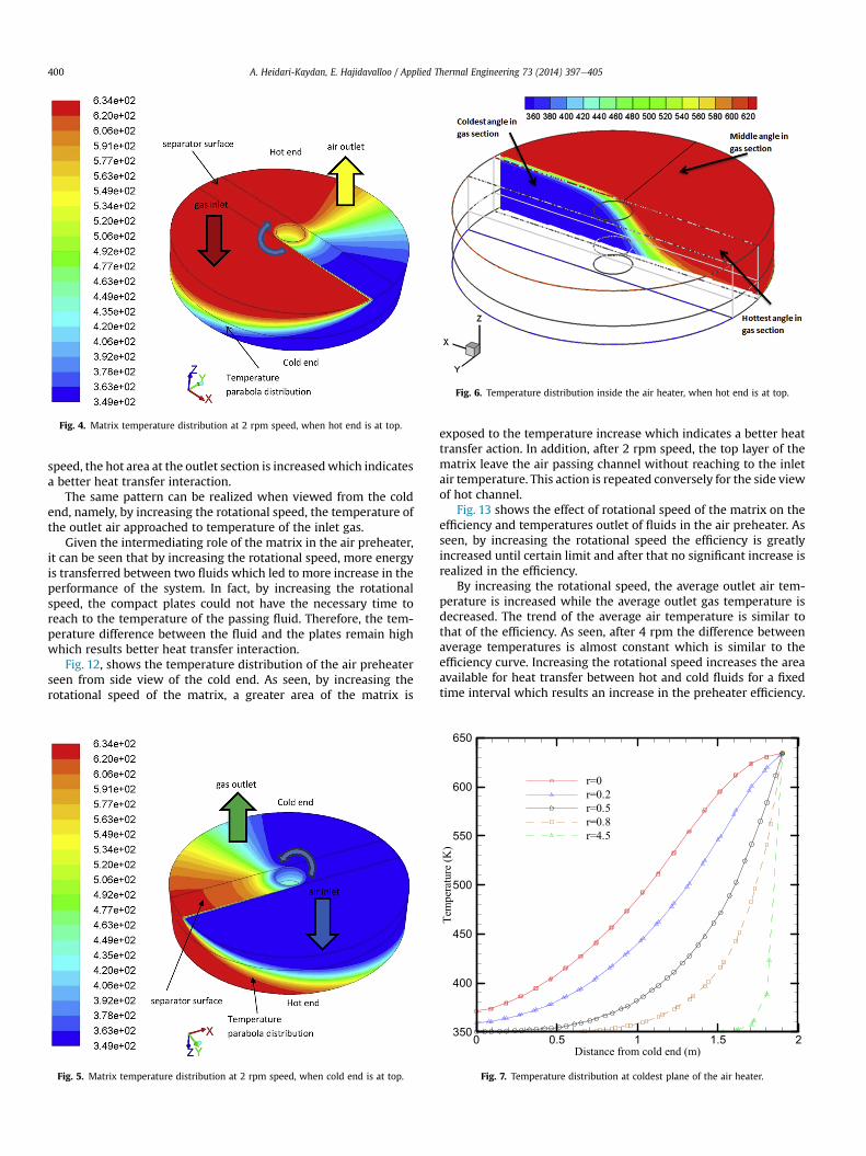
Fig. 4. Matrix temperature distribution at 2 rpm speed, when hot end is at top.
Fig. 6. Temperature distribution inside the air heater, when hot end is at top.
A. Heidari-Kaydan, E. Hajidavalloo / Applied Thermal Engineering 73 (2014) 397e405400
speed, the hot area at the outlet section is increasedwhich indicatesa better heat transfer interaction.
The same pattern can be realized when viewed from the coldend, namely, by increasing the rotational speed, the temperature ofthe outlet air approached to temperature of the inlet gas.
Given the intermediating role of the matrix in the air preheater,it can be seen that by increasing the rotational speed, more energyis transferred between two fluids which led to more increase in theperformance of the system. In fact, by increasing the rotationalspeed, the compact plates could not have the necessary time toreach to the temperature of the passing fluid. Therefore, the tem-perature difference between the fluid and the plates remain highwhich results better heat transfer interaction.
Fig. 12, shows the temperature distribution of the air preheaterseen from side view of the cold end. As seen, by increasing therotational speed of the matrix, a greater area of the matrix is
Fig. 5. Matrix temperature distribution at 2 rpm speed, when cold end is at top.
exposed to the temperature increase which indicates a better heattransfer action. In addition, after 2 rpm speed, the top layer of thematrix leave the air passing channel without reaching to the inletair temperature. This action is repeated conversely for the side viewof hot channel.
Fig. 13 shows the effect of rotational speed of the matrix on theefficiency and temperatures outlet of fluids in the air preheater. Asseen, by increasing the rotational speed the efficiency is greatlyincreased until certain limit and after that no significant increase isrealized in the efficiency.
By increasing the rotational speed, the average outlet air tem-perature is increased while the average outlet gas temperature isdecreased. The trend of the average air temperature is similar tothat of the efficiency. As seen, after 4 rpm the difference betweenaverage temperatures is almost constant which is similar to theefficiency curve. Increasing the rotational speed increases the areaavailable for heat transfer between hot and cold fluids for a fixedtime interval which results an increase in the preheater efficiency.
Fig. 7. Temperature distribution at coldest plane of the air heater.

Fig. 8. Temperature distribution at hottest plane of the air heater.
A. Heidari-Kaydan, E. Hajidavalloo / Applied Thermal Engineering 73 (2014) 397e405 401
On the other hand, it decreases the maximum temperature of thebaskets when they are in the hot section and increases the mini-mum temperature of the baskets when they are in the cold sectionwhich results a decrease in the preheater efficiency. The balancebetween these two opposite effects determines the trend of effi-ciency curve.
Fig. 9. Effect of separator plate on the temperature d
Fig. 10. Temperature distribution without separat
The effect of rotational speed of thematrix on themaximum andminimum temperatures of the outlet fluids are shown in Fig. 14.Rotational speed has no significant effect on the minimum gasoutlet temperature and the maximum air outlet temperature. Theminimum gas outlet temperature is important due to the dew pointformation in the preheater and matrix corrosion. Since rotationalspeed has no effect on the onset of fluid condensation and dewpoint, it can be concluded that the corrosion process could not beprevented by changing the rotation speed.
In the other side, the minimum outlet air temperature and themaximum outlet gas temperature are affected by the rotationalspeed, as seen in Fig. 14. The onset, where these effects areappeared, is approximately at 2 rpm when the matrix could notreach to the temperature of the inlet fluid in each channel. Inaddition, the minimum outlet air temperature and the maximumoutlet gas temperature have the same trend to the average air andgas outlet temperatures, respectively.
The effect of speed on the minimum outlet air and themaximum outlet gas temperatures indicates that despite therotational speed does not affect the onset of the condensation; it isinfluential on the exposed area of the condensation. The mostcorrosion is usually happened in the lower layer of thematrix whenthe cold matrix initially enters to the gas channel in the surfacesclose to the perimeter.
5. The effect of air and gas flow rate
The other important parameter affecting the performance of arotary preheater is the flow rate of fluids. Assuming the same flowrate for both fluids, the effect of flow rate on the efficiency and the
istribution, a) from cold side, b) from hot side.
or plate, a) from cold side, b) from hot side.

Fig. 11. Effect of rotational speed on the temperature distribution seen from the hot end.
Fig. 12. Effect of rotational speed on the temperature distribution seen from side view.

Fig. 13. Effect of rotational speed on the air preheater efficiency and average tem-peratures of outlet air and gas.
Fig. 15. Effect of flow rate on the efficiency and average outlet temperatures.
Table 4Material specifications.
Metals material Thermaldiffusivity,m2/s
Thermalconductivity,W/m K
Heat capacityJ/kg K
Densitykg/m3
�4
A. Heidari-Kaydan, E. Hajidavalloo / Applied Thermal Engineering 73 (2014) 397e405 403
average gas and air outlet temperature are shown in Fig. 15. Byincreasing the flow rate, the average air temperature is decreasedwhile the average outlet gas temperature is increased, resulting adecrease in air preheater performance. This reduction is due to lackof matrix capacity for energy transfer.
Copper 10 � 1.13 386 380 8954Aluminium (T 351) 10�5 � 6.42 143 795 2800Aluminium 10�5 � 3.13 220 896 2707Carbon steel 0.5% 10�5 � 1.4 54 465 7833Curtin steel 10�6 � 7.6 25 460 7700Stainless steel 10�6 � 4.2 16.26 502.1 8027.2
6. The effect of material type
To study the effect of different plates' material on the perfor-mance of air preheater, six different metals were used in thesimulation as shown in Table 4.
The simulation result for air heater performance is presented inFig. 16. As seen, stainless steel has the highest efficiency whilecopper show the least efficiency. Fig. 16 suggests that material withthe least thermal diffusivity is appropriate for the air preheaterconsidering only technical issue; however, the final selection of
Fig. 14. Effect of rotational speed on the outlet fluids minimum and maximumtemperatures.
material depends on the many operational and economical pa-rameters. It should be noted that the difference between effi-ciencies are not very significance.
7. The effect of inlet air temperature on the efficiency
To prevent the condensation on the matrix and formation ofcorrosive acids; one possible way is preheating the cold inlet air toreach a temperature between 65 and 85 �C by using a specific typeof heat exchanger known as 'clarifier'. Thermal energy for clarifier issupplied by steam coming from the turbine subsections. Althoughusing clarifier results in lower power production in the power plant
Fig. 16. Effect of plates' material on the efficiency.

Fig. 17. Effect of inlet air temperature increase on the outlet temperatures.
A. Heidari-Kaydan, E. Hajidavalloo / Applied Thermal Engineering 73 (2014) 397e405404
but from economical point of view it has benefit for the powerplant.
Based on the simulation results presented in Fig. 17, increasinginlet air temperature around 20 �C increases the average outlet gastemperature up to 13.9 �C and the average outlet air temperaturearound 6.1 �C. The exchanger efficiency is almost untouched andremains constant. Moreover, it could be shown that the minimumoutlet gas temperature increases equal to the increase of airtemperature.
The inlet gas temperature change has the same effect as the inletair temperature on the average outlet air and gas temperatures. Thesimulation results presented in Fig. 18, shows the effect of inlet gastemperature on the average outlet gas and air temperatures. Asseen, a 20 �C increase in the inlet gas temperature increases theaverage outlet gas and air temperature around 6.1 �C and 13.9 �C,respectively. This increase has no effect on the efficiency of rotarypreheater.
Fig. 18. Effect of inlet gas temperature increase on the outlet temperatures.
8. Conclusion
Simulation of a rotary preheater was performed by consideringthe rotary matrix as a porous media and using FLUENT software.The results indicated that the isothermal lines within thematrix arealmost linear except close to the center of the matrix. The matrixtemperature is smoothly changed in the angular direction untilapproach to the inlet temperature of either air or hot gas. Existing ofthe separator plate changes the temperature distribution in thematrix especially close to the center. It was found that the rotationalspeed has significant effect on the preheater efficiency. Increasingthe rotational speed, initially, increases the efficiency very rapidlyup to a certain limit after that there is not any significant change.The effect of fluid flow rate on the performance of air heater wasstudied. It was shown that by increasing the air and gas flow ratethe performance was decreased.
The rotational speed and fluid flow rates have no impact on theminimum outlet gas and the maximum outlet air temperatures.They are only effective in the minimum outlet air and themaximum outlet gas temperatures. By analyzing thematerials usedin the rotary preheater, it was found that material with low thermaldiffusivity have better thermal efficiency. However, the materialchange had only a slight effect on the overall efficiency.
The effects of air and gas inlet temperatures were also studied.The results showed that by increasing the inlet air temperature, theaverage temperature of the outlet gas increased 2.2 times morethan the average temperature increase of the outlet air. This phe-nomenon helps in becoming far from the dew point temperature ofthe flow.
References
[1] T. Museet, The Ljungstrom Air Preheater 192, ASME History, 1995.[2] I. Warren, Ljungstrom heat exchangers for waste heat recovery, Heat Recovery
Syst. CHE 2 (3) (1982) 257e271.[3] T. Skiepko, Method of monitoring and measuring seal clearances in a rotary
heat exchanger, Heat Recovery Syst. CHE 8 (5) (1988) 469e473.[4] T. Skiepko, Experimental results concerning seal clearances in some rotary
heat exchangers, Heat Recovery Syst. CHE 8 (6) (1988) 577e581.[5] T. Skiepko, The effect of matrix longitudinal heat conduction on the temper-
ature fields in the rotary heat exchanger, Int. J. Heat Mass Transf. 31 (11)(1988) 2227e2238.
[6] T. Skiepko, Effect of parameter values on gas and matrix temperature fields inrotary heat exchangers, Int. J. Heat Mass Transf. 32 (8) (1989) 1143e1447.
[7] P. Worsoe-Schmidt, Effect of fresh air purging on the efficiency of energyrecovery from exhaust air in rotary regenerators, Int. J. Refrig. 14 (4) (1991)233e239.
[8] N. Ghodsipour, M. Sadrameli, Experimental and sensitivity analysis of a rotaryair preheater for the flue gas heat recovery, Appl. Therm. Eng. 23 (5) (2003)571e580.
[9] B. Drobnic, J. Oman, M. Tuma, A numerical model for the analyses of heattransfer and leakages in a rotary air preheater, Int. J. Heat Mass Transf. 49(25e26) (2006) 5001e5009.
[10] S. Sanaye, S. Jafari, H. Ghaebi, Optimum operational conditions of a rotaryregenerator using genetic algorithm, Energy Build. 40 (9) (2008) 1637e1642.
[11] H.Y. Wang, L.L. Zaho, Z.G. Xu, W.G. Chun, H.T. Kim, The study on heat transfermodel of tri-sectional rotary air preheater based on the semi-analyticalmethod, Appl. Therm. Eng. 28 (14e15) (2008) 1882e1888.
[12] M. Mousavi, M. Passandideh-Fard, M. Ghazikhani, Numerical simulation offluid flow and heat transfer in a rotary regenerator, in: The 16th AnnualConference of the CFD Society of Canada, 2008.
[13] N.B. Khedher, S.B. Nasrallah, Three-dimensional modeling and analysis of aporous thermal energy storage system, J. Appl. Fluid Mech. 3 (2) (2010)97e109.
[14] L.A. Sphaier, W.M. Worek, Analysis of heat and mass transfer in porous sor-bents used in rotary regenerators, Int. J. Heat Mass Transf. 47 (14e16) (2004)3415e3430.
[15] J. Dallaire, L. Gosselin, A.K. da Silva, Conceptual optimization of a rotary heatexchanger with a porous core, Int. J. Therm. Sci. 49 (2) (2010) 454e462.
[16] D.A. Nield, A. Bejan, Convection in Porous Media, third ed., Springer, NewYork, 2006, pp. 4e23.
[17] W.J. Minkowycz, A. Haji-Sheikh, K. Vafai, On departure from local thermalequilibrium in porous media due to a rapidly changing heat source: thesparrow number, Int. J. Heat Mass Transf. 42 (18) (1999) 3373e3385.

A. Heidari-Kaydan, E. Hajidavalloo / Applied Thermal Engineering 73 (2014) 397e405 405
[18] T. Skiepko, R.K. Shah, Modeling and effect of leakages on heat transfer per-formance of fixed matrix regenerators, Int. J. Heat Mass Transf. 48 (8) (2005)1608e1632.
Nomenclature
cp: constant pressure specific heat (J kg�1 K�1)DH: hydraulic diameterE: relative internal energyF: external body forcesh: heat transfer coefficient (W m�2 K�1)H: relative total enthalpyk: thermal conductivity (W m�1 K�1)K: permeability (m2)L: porous layer thickness (m)_m: mass flow rate of cold or hot fluid (kg s�1)P: pressure (pa)q0 0 0: heat production (W m�3)
Re: Reynolds numberSh: heat sourcesSp: Sparrow numbert: time (s)T: temperature (K)
ur: velocity of the moving frame relative to the inertial reference framev: (u,v,w), seepage velocity (m s�1)v: absolute velocityvr : relative velocityvt : translational frame velocityV: fluid velocity (m s�1)
Greek letters
u: angular velocityg: porosityε: efficiencym: dynamic viscosity (N s m�2)r: density (kg m�2)tr : relative stress tensor
Subscript
s: solidf: fluidm: mixturein: outlet fluidout: inlet fluid